WO2020129967A1 - 組合せ計量装置 - Google Patents
組合せ計量装置 Download PDFInfo
- Publication number
- WO2020129967A1 WO2020129967A1 PCT/JP2019/049360 JP2019049360W WO2020129967A1 WO 2020129967 A1 WO2020129967 A1 WO 2020129967A1 JP 2019049360 W JP2019049360 W JP 2019049360W WO 2020129967 A1 WO2020129967 A1 WO 2020129967A1
- Authority
- WO
- WIPO (PCT)
- Prior art keywords
- base body
- weighing device
- combination weighing
- weighing
- parallel
- Prior art date
- Legal status (The legal status is an assumption and is not a legal conclusion. Google has not performed a legal analysis and makes no representation as to the accuracy of the status listed.)
- Ceased
Links
Images





Classifications
-
- G—PHYSICS
- G01—MEASURING; TESTING
- G01G—WEIGHING
- G01G19/00—Weighing apparatus or methods adapted for special purposes not provided for in the preceding groups
- G01G19/387—Weighing apparatus or methods adapted for special purposes not provided for in the preceding groups for combinatorial weighing, i.e. selecting a combination of articles whose total weight or number is closest to a desired value
- G01G19/393—Weighing apparatus or methods adapted for special purposes not provided for in the preceding groups for combinatorial weighing, i.e. selecting a combination of articles whose total weight or number is closest to a desired value using two or more weighing units
-
- G—PHYSICS
- G01—MEASURING; TESTING
- G01G—WEIGHING
- G01G21/00—Details of weighing apparatus
- G01G21/28—Frames, Housings
Definitions
- the present invention relates to a combination weighing device for combining and weighing various articles such as foods and confectionery in predetermined amounts, and particularly to a combination weighing device suitable for mixing and weighing small amounts of various kinds of articles.
- Patent Document 1 As a combination weighing device suitable for mixing and weighing a wide variety of articles, for example, there is one described in Patent Document 1.
- a large number of weighing units including a feeding hopper and a weighing hopper are linearly mounted in parallel on both sides of a horizontally long center base that is installed and fixed, and articles are fed to the feeding hoppers of each of these weighing units.
- the supply units are arranged on both sides of the center base body.
- the combination weighing device is configured so that the hoppers of the weighing unit can be detached from the center base body for cleaning work and maintenance work accompanying the change of product type.
- the entire supply unit is moved in the direction of separating from the center base body to form a working space in front of the weighing unit group into which an operator can enter. I am trying.
- the supply unit is provided with a group of tanks that store various types of articles and a large number of linear feeders that are arranged in parallel so as to send the articles sent from each tank to the supply hopper of the corresponding weighing unit.
- the entire supply unit is a heavy object, and it requires a considerable amount of labor to move it.
- the tank capacity is increased to perform automatic operation for a long time, the weight of the stored articles also becomes considerably heavy, which requires more labor to move the supply unit.
- the present invention has been made by paying attention to such a point, and in a horizontal combination weighing device in which weighing unit groups are arranged in parallel, the weighing units can be easily exposed and exposed without requiring a large labor, The purpose is to enable cleaning work and maintenance work.
- the present invention is configured as follows.
- the combination weighing device includes a horizontally long base body in which a plurality of weighing units including a weighing hopper are installed in parallel, and the base body is centered on a vertical fulcrum of one end in the horizontal direction. It is rotatable.
- the plurality of weighing units can be largely exposed by rotating the base body equipped with the plurality of weighing units in parallel.
- the base body since the weight of the article storage tank and the straight feeder is not acting on the base body, the base body can be lightly rotated.
- cleaning work and maintenance work of the exposed weighing unit can be easily performed.
- a cross roller bearing that receives a rotation shaft of the base body is provided below the one end portion in the lateral direction.
- the rotating shaft can be smoothly rotated by any of the bending moment load, the radial load and the thrust load by the cross roller bearing that receives the lower end of the rotating shaft of the base body. Further, it is possible to reduce the size as compared with a configuration in which a plurality of bearings other than the cross roller bearing are provided above and below the rotation shaft of the base body, for example.
- a torque hinge capable of holding the base body at an arbitrary rotational position is provided.
- the torque hinge imparts a resistance torque to the rotation of the base body, so that the base body can be held at an arbitrary rotation position.
- a rotation range regulation unit that regulates the rotation range of the base body is provided.
- the turning radius for turning one of the two bases is equal to that of all the weighing units. It is possible to make it sufficiently smaller than the turning radius when the equipment is installed in parallel with each other.
- a self-locking lock mechanism for locking and fixing the base body at a predetermined position.
- the rotated base body when the rotated base body is returned to the original predetermined position, it is automatically locked, and it is not necessary to perform a troublesome fixing operation such as a screw tightening operation.
- a clamp mechanism is provided that elastically presses the base body at the predetermined position in a direction in which the base body is prevented from rotating by a clamp fitting.
- the base body at a predetermined position is elastically pressed and clamped by the clamp metal fittings, highly accurate weighing can be performed in the weighing unit without being affected by vibration.
- the clamp mechanism is shared by two bases arranged in parallel in a horizontal row.
- the clamp structure can be simplified as compared with the case where each base is equipped with the clamp mechanism. Further, since both bases can be clamped or unclamped by one operation, the handling becomes high.
- the plurality of weighing units can be largely exposed by rotating the base body provided with the plurality of weighing units in parallel.
- the base body since the weight of the article storage tank and the straight feeder is not acting on the base body, the base body can be lightly rotated.
- cleaning work and maintenance work of the exposed weighing unit can be easily performed.
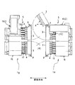
- FIG. 1 is a schematic side view of a combination weighing device according to an embodiment of the present invention.
- FIG. 2 is a schematic plan view of the combination weighing device of FIG.
- FIG. 3 is a schematic front view of one of the weighing devices of FIG.
- FIG. 4 is a schematic front view of the other weighing device of FIG. 1.
- FIG. 5 is a side view of the main part of the weighing device.
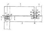
- FIG. 6 is a partially cutaway front view showing the support structure of the base body.
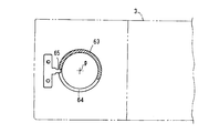
- FIG. 7 is a sectional view taken along line AA in FIG.
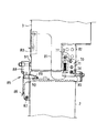
- FIG. 8 is a side view showing the lock mechanism with the base body locked in a predetermined position.
- FIG. 9 is a side view showing the lock mechanism in the unlocked state.
- FIG. 1 is a schematic side view of a combination weighing device according to an embodiment of the present invention.
- FIG. 2 is a schematic plan view of the combination weighing device of FIG.
- FIG. 3 is a schematic front view of one
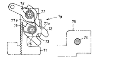
- FIG. 10A is a side view showing a locked state of the lock mechanism.
- FIG. 10B is a side view showing the unlocked state of the lock mechanism.
- FIG. 10C is a side view showing a moving state of the base body of the lock mechanism.
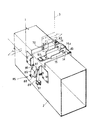
- FIG. 11 is a perspective view of the base free end portion.
- FIG. 1 is a schematic side view of a combination weighing device according to an embodiment of the present invention
- FIG. 2 is a schematic plan view thereof
- 3 and 4 are schematic front views of the weighing device.
- the combination weighing device of this embodiment is a device for combining and weighing various kinds (for example, 8 kinds) of articles such as various foods and confectionery in predetermined small amounts.
- This combination weighing device is installed on the first floor surface F1 and is used in a packaging line that puts the weighed articles into a packaging device (not shown) installed below the floor surface and packs them.
- the lateral direction in FIGS. 1 and 2 and the front-back direction of the paper in FIGS. 3 and 4 are referred to as the front-back direction.
- the front-back direction of the paper surface in FIG. 1 and the lateral direction in FIGS. 3 and 4 are referred to as the left-right direction.
- this combination weighing device has a structure in which a pair of front and rear weighing devices 1A and 1B are arranged face-to-face with a center passage R through which a worker can move left and right sandwiched. ..
- the weighing devices 1A and 1B are basically configured to have the same specifications, and the detailed structure of the weighing devices 1A and 1B will be described below.
- each of the weighing devices 1A and 1B are horizontally installed at a predetermined height position via a support frame 2 standing on the first floor surface F1.
- a large number of measuring units 4 are installed in a line in the left and right.
- each weighing device 1A, 1B is equipped with a row of 12 weighing units 4, and 24 weighing units 3 including both weighing devices 1A, 1B perform mixed combination weighing of various kinds of articles. It is like this.
- an article supply unit 5 for supplying various types of articles to be weighed to the upper portion of each weighing unit 4 is provided.
- the weighing unit 4 is basically the same as the conventional one.
- the series of weighing units 4 stores a product delivered from the product supply unit 5, and stores and temporarily stores and discharges the product, and a storage hopper 6 having an openable and closable gate, and stores the product discharged from the supply hopper 6.
- the structure is arranged vertically in rows.
- the supply hopper 6, the weighing hopper 7, and the memory hopper 8 are detachably supported on the base body 3.
- a gate drive mechanism of the hoppers 6, 7, and 8, a weight sensor for weighing the weighing hopper 6, and the like are housed in the base body 3.
- Each base body 3 provided with eight weighing units 4 is rotatably supported on the upper part of the support frame 2 about a vertical fulcrum p at one lateral end.
- the base 3 is rotated to the central passage R side to expose the weighing unit group 4 to facilitate the attachment and detachment and maintenance of the hoppers, as shown by phantom lines in FIG. You can do it.
- the rotation support structure for the base 3 will be described later.
- the lower end of the weighing hopper 7 is provided with an outer gate 7a and an inner gate 7b that can be independently opened and closed.
- the weighed articles are delivered directly to the lower first collecting chute 9 through the first delivery path (a), and by swinging and opening only the inner gate 7b, The weighed articles are sent to the memory hopper 8 through the second delivery path (b) and temporarily stored.
- each weighing unit 4 is provided with the memory hopper 8
- the memory hopper 8 can also participate in the combination calculation in addition to the weighing hopper 7, and the number of hoppers (effective hoppers) that can participate in the combination calculation is increased. be able to.
- a plurality of weighing hoppers 7 selected by a combination calculation so as to have a predetermined weight, or a first set of four collecting the articles dropped and delivered from the memory hopper 8.
- the chutes 9 are arranged in a line on the left and right.
- Two first collecting hoppers 10 that temporarily receive and store the articles collected by the first collecting chutes 9 are provided below the two first collecting chutes 9 adjacent to each other.
- a second collecting chute 11 that guides the articles dropped and discharged from each of the first collecting hoppers 10 by sliding down and collecting them.
- One is arranged for each.
- a final collecting hopper 13 for collecting the articles discharged from the second collecting hopper 12 provided for each of the weighing devices 1A and 1B in one place is installed. Has been done.
- the final collecting hopper 13 is controlled to open and close based on a supply request command from the packaging device side.
- a metal detector 14 is provided in the guide path along which the articles flow from the second collecting hopper 12 to the final collecting hopper 13, and the mixing of metallic foreign matters is monitored.
- the article supply unit 5 is provided with storage tanks 15 for storing articles and storage hoppers 16 connected to the lower ends of the storage tanks 15. Further, in the article supply unit 5, twelve linear feeders 17 that vibrate and convey the articles fed from the lower end of the storage hopper 16 toward the twelve stations of the weighing units 4 are arranged side by side on the upper side of the support table 18. Have been deployed.
- the storage tank 15 includes a lower tank 15a that is dropped and supported in an opening of a second floor F2 that is installed further above the first floor F1, and a middle tank 15b and an upper tank that are removably positioned and supported thereon. It is composed of a tank 15c.
- a storage hopper 16 is detachably supported at the lower end of the lower tank 15a.
- the linear feeder 17 includes an upstream linear feeder 17a on the upstream side in the conveying direction of an article and a downstream linear feeder 17b on the downstream side, which are vertically arranged in a step-down manner toward the conveying direction. .. That is, the upstream straight feeders 17a are arranged in the upper row and the downstream straight feeders 17b are arranged in the lower row.
- Each of the linear feeders 17a and 17b includes trough-shaped troughs 19a and 19b having a groove-shaped cross-sectional shape, and vibrating mechanisms 20a and 20b installed above the support base 18.
- Each trough 19a, 19b is detachably connected to the vibrating head portion of each vibrating mechanism 20a, 20b.
- the articles thrown into and supplied from the storage hopper 16 to the upstream linear feeder 17a are unwound while being vibrated and conveyed, transferred to the downstream linear feeder 17b, and sent to the supply hopper 6 of the weighing unit 4 little by little from the end of the downstream linear feeder 17b. Be done.
- Article sensors 21a and 21b for detecting the stacking height of articles near the start end and the end of the downstream rectilinear feeder 17b with a laser, for example, are provided above the rectilinear feeder 17, respectively.
- the vibrating mechanisms 20a and 20b are drive-controlled based on the detection information of the article sensors 21a and 21b, so that the articles can be conveyed uniformly in each of the linear feeders 17.
- the tank configuration and feeder configuration described above are of standard specifications for supplying articles that do not stick to each other, such as nuts, confectionery, hail, and the like.
- a part of the straight-line feeders 17 for transporting small sticky items such as small fish mirin and small light rice crackers little by little and the corresponding storage tanks 15 are configured differently.
- 15(C) is another specification different from the standard specification.
- a wide belt conveyor 35 is used to smoothly deliver the articles that are difficult to flow down by gravity.
- the belt conveyor 35 is arranged so as to horizontally rotate along the lower portion of an upper tank 36 having a rectangular tubular shape.
- the articles stored in the upper tank 36 are forcibly conveyed from the bottom of the article, widely dropped and delivered, and fed into the storage hopper 16 through the lower tank 15a.
- the storage tank 15(C) of the one weighing device 1A and the storage tank 15(C) of the other weighing device 1B have different installation postures. That is, in the storage tank 15(C) of the one weighing device 1A, the belt conveyor 35 is rotated in the front-rear direction parallel to the conveyance direction of the articles of the linear feeder 17, while the other weighing device 1B is rotated. In the storage tank 15(C), the belt conveyor 35 is configured to rotate in the left-right direction orthogonal to the article conveying direction of the straight-line feeder 17.
- Articles sent from the end of the belt conveyor 35 are guided to the storage hopper 16 via the lower tank 15a.
- the article dispersion guide portion 37 is incorporated inside the lower tank 15a.
- the article dispersion guide unit 37 is configured by arranging a pair of dispersion funnels 38 in parallel in the width direction of the belt conveyor 35.
- articles that have been widely dropped and discharged in the belt width direction from the end of the belt conveyor 35 to the upper part of the lower tank 15a are distributed in the feeder parallel direction by the flow-down guides of the two dispersion funnels 38. There is.
- the support table 18 in the article supply unit 5 is provided with a reject mechanism 50 for discharging an excessive amount of articles supplied to the weighing hopper 6 and exceeding an appropriate amount range.
- the reject mechanism 50 is equipped with a reject chute 51 that can be moved forward and backward horizontally and a recovery chute 52 and a recovery container 53 for collecting the articles introduced into the reject chute 51.
- the reject chute 51 is provided so as to face the first delivery path (a) of the weighing hopper 7 from the front outside.
- the reject chute 51 is driven forward and backward by an air cylinder 54. At normal times, as shown in FIG. 5, the reject chute 51 is retracted to the outside of the first delivery path (a). At this normal time, the reject chute 51 does not hinder the discharge of the articles to the first collecting chute 9 due to the opening of the outer gate 7a in the weighing hopper 7.
- the reject chute 51 enters the first delivery path (a) in a reject state.
- the outer gate 7a of the weighing hopper 7 is opened, whereby the articles in the weighing hopper 7 are discharged to the reject chute 51, and the excessive amount of articles is flowed down and collected into the collection container 53 via the collection chute 52. It When the collection is completed, the reject chute 51 is moved to the original position retracted from the first delivery path (a), and the outer gate 7a of the weighing hopper 7 is closed to prepare for the next weighing.
- a guide member 55 made of a plate material is provided at the tip of the reject chute 51.
- the guide member 55 is located at a position facing the first delivery path (a) from the outside when the reject chute 51 is at a position retracted from the first delivery path (a) to the outside. At this position, the guide member 55 prevents the articles discharged by the outer gate 7a of the weighing hopper 7 being opened, and properly guiding the delivered articles to the first collecting chute 9. ing.
- 6 to 11 show a rotation support structure and a fixing structure for the base body 3.
- FIG. 6 is a partially cutaway front view showing the rotation support structure of the base body 3.
- a cross roller bearing 61 and a torque hinge 62 are provided at the fulcrum p of the base body 3.
- the cross roller bearing 61 receives a lower portion of a rotating cylinder shaft 63, which is a cylindrical rotating shaft to which the base end portion of the base body 3 is connected, and receives any of bending moment load, radial load, and thrust load.
- the rotating cylinder shaft 63 can be smoothly rotated even with respect to it. Since the cross roller bearing 61 is used in this manner, the base body 3 can be rotatably supported by the support underframe 2 at one location below the fulcrum p. Further, it is not necessary to provide bearings other than the cross roller bearings above and below the rotary cylinder shaft 63 of the base body 3, and it is possible to achieve miniaturization.
- the torque hinge 62 can apply a resistance torque to the rotation of the base body 3, and the base body 3 can be held at an arbitrary rotation stop position.
- FIG. 7 which is a sectional view taken along the line AA of FIG. 6, a slit 64 is formed along the circumferential direction on the outer periphery of the rotating cylinder shaft 63 of the base body 3.
- a locking metal fitting 65 fixedly arranged on the support frame 2 side is engaged with the slit 64, and the base body 3 can be rotated within an angular range (for example, 150 degrees) in which the slit 44 is formed.
- the slit 64 formed on the rotating cylinder shaft 63 of the base body 3 and the locking metal fitting 65 that is fixedly arranged constitute a rotation range restricting portion that restricts the rotation range of the base body 3.
- a lock mechanism 70 for closing and fixing the base body 3 at a predetermined position is provided at a free end portion of the base body 3 opposite to the fulcrum p.
- FIG. 8 is a side view showing the lock mechanism 70 in a state where the base body 3 is locked at a predetermined position which is a set position for operating the combination weighing device, and FIG. 9 shows the lock mechanism 70 in an unlocked state. It is a side view. 10A to 10C are side views showing the operating procedure of the lock mechanism 70. FIG. 10A shows a locked state, FIG. 10B shows an unlocked state, and FIG. 10C shows a substrate moving state.
- a known latch structure is used for this locking mechanism 70.
- a lock fitting 72 is supported by a case 71 fixedly connected to the end surface of the base body 3 so as to be rotatable around a lateral fulcrum x.
- the base 3 can be fixed at a predetermined position by engaging the engaging recess 73 formed in the lock metal fitting 72 with the locking pin 74 which is laterally fixed and disposed on the support frame 2 side.
- a common bracket 75 in which the locking pins 74 of the lock mechanisms 70 in the pair of bases 3 that are pivoted in a double-door shape is fixed to the upper surface of the support frame 2 at the center in the left-right direction. Is attached to.
- the lock fitting 72 is rotationally biased in a certain direction (counterclockwise in FIGS. 10A to 10C) by a torsion spring 76.
- a torsion spring 76 In the free state, the lock fitting 72 is urged and abutted against the stopper piece 71a that is bent and formed on the case 71 to be held in a certain standby posture.
- a locking metal fitting 77 that engages with the outer periphery of the boss portion of the lock metal fitting 72 is provided so as to be rotatable around a lateral fulcrum y.
- the locking metal fitting 77 is rotationally biased in the direction opposite to the lock metal fitting 72 (clockwise in FIGS. 10A to 10C) by a torsion spring 78 that is connected in series with the torsion spring 76.
- An engagement step 79 is formed on the outer periphery of the boss of the lock fitting 72, on which the engagement projection 77a of the locking fitting 77 acts.
- the locking fitting 77 is biased and abutted on the outer periphery of the boss portion of the lock fitting 72 at a position beyond the engagement step 79.
- the lock fitting 72 is rotated by an external force against the torsion spring 76 and the engagement concave portion 73 is in a lock posture in which it is directed downward, the engagement projection 77 a of the locking fitting 77 is biased to the engagement step 79. Even if the lock fitting 72 is engaged and the external force is removed from the lock fitting 72, the biasing return of the lock fitting 72 to the standby posture is prevented, and the lock posture is maintained.
- the other end of the locking metal fitting 77 is linked via a wire 81 to a lock release knob 80 provided on the front surface of the base body 3 on the free end side, as shown in FIG.
- a lock release knob 80 provided on the front surface of the base body 3 on the free end side, as shown in FIG.
- the lock mechanism 70 is attached to the end surface of the base body 3 via a spacer 82 made of a thick plate material.
- a stopper bolt 83 extending toward the central passage R is provided in the bracket extension portion 75a that is continuously provided to the bracket 75 for attaching the locking pin. As shown in FIG. 8, when the base body 3 is at a predetermined position, the stopper bolts 83 are brought into contact with the ends of the spacers 82 and positioned. At this time, the lock fitting 72 of the lock mechanism 70 is held in the locked posture in which it is engaged with the locking pin 74.
- a toggle-type clamp mechanism 85 is provided on the upper part of the support underframe 2 on the side of the central passage R.
- the clamp mechanism 85 includes an operating lever 86 that operates beyond the dead center, a clamp metal fitting 88 that is integrally connected to the operating lever 86 via a support shaft 87, and a clamp spring 89 that is a leaf spring.
- a fixed hook 90 corresponding to the clamp spring 89 is installed on the upper surface of the support frame 2.
- the operation lever 86 With the tip of the clamp spring 89 locked to the fixed hook 90, the operation lever 86 is rocked downward to operate beyond the dead point. As a result, the clamp metal fitting 88 is urged via the clamp spring 89, and the front surface of the base body 3 is elastically moved backward by the stopper bolt 91 provided at the tip of the clamp metal fitting 88, that is, in the direction in which the rotation of the base body 3 is blocked. Abuttingly pressed. As a result, the base body 3 locked at the predetermined position is elastically clamped by the front and rear stopper bolts 83 and 91, and the front and rear vibration of the base body 3 is prevented.
- the clamp mechanism 85 is shared by the two bases 3 adjacent to each other on the left and right, and the clamp metal fittings 88 are connected to the left and right of the common operation lever 86.
- the operation lever 86 of the clamp mechanism 85 is operated to move toward the upper dead center to the dead point. Thereafter, by releasing the clamp spring 89 from the fixing hook 90, the clamp metal fitting 88 can be retracted outward and downward together with the operating lever 86 as shown in FIG. To release.
- the lock release knob 80 is pulled to release the engagement of the lock fitting 77 with the lock fitting 72.
- the lock fitting 72 is biased and rotated toward the standby position, and the lock fitting 72 is biased and rotated with respect to the fixed locking pin 74, so that the free end portion of the base body 3 is relatively forward. It is pushed out a little toward the central passage R side.
- the base body 3 can be manually rotated to an arbitrary position, and the hoppers can be attached and detached and the maintenance can be performed on the base body 3 that has been largely opened.
- the lock fitting 72 in the standby position engages with the locking pin 74. Subsequently, when the base body 3 is strongly pushed and rotated until it abuts on the stopper bolt 83, the lock fitting 72 abutting on the locking pin 74 is relatively rotated against the torsion spring 76, and the lock fitting 72 is automatically rotated. Is locked by the locking metal fitting 77.
- the operation lever 86 of the clamp mechanism 85 is lifted up to lock the clamp spring 89 on the fixed hook 90, and then the operation lever 86 is operated downward to the dead point.
- the front surface of the base body 3 can be urged rearward by the stopper bolt 91 of the clamp metal fitting 88 to fix the base body 3 at a predetermined position in a vibration-proof state.
- the plurality of weighing units 4 can be largely exposed by rotating the base body 3 equipped with the plurality of weighing units 4 in parallel from a predetermined position. As a result, cleaning work and maintenance work of the exposed hoppers of the weighing unit 4 can be easily performed.
- the base body 3 can be fixed at a predetermined position so as not to be affected by vibration, highly accurate combined weighing becomes possible.
- the lock mechanism 70 having the above-described configuration having the self-locking function may be provided on the support underframe 2 side and the locking pin 74 may be provided on the base body 3 side.
- the free end of the base body 3 located at a predetermined position may be fastened and fixed to the support underframe 2 with a bolt with a handle or a bolt with a knob.
- lock mechanism 70 having the self-locking function various known structures can be used in addition to the structure in which the lock fitting 72 is rotated as in the above embodiment. It is also possible to use a form in which it is linearly slid to engage with and disengage from a locking pin or a locking hole.
- a means for detecting whether or not the base body 3 is at a predetermined position is provided, and a fail-safe function that enables the metering operation only when it is detected that the base body 3 is correctly at the predetermined position is provided. Good.
- the clamp mechanism 85 may be individually provided for each base body 3.
Landscapes
- Physics & Mathematics (AREA)
- General Physics & Mathematics (AREA)
- Weight Measurement For Supplying Or Discharging Of Specified Amounts Of Material (AREA)
Abstract
複数の計量ユニットを並列に装備した横型の組合せ計量装置において、計量ホッパを含む計量ユニットの複数を並列に装備した横長の基体を、その横方向の一端部の縦向き支点を中心にして回動可能に支持台枠に装着支持している。
Description
本発明は、食品や菓子類等の各種の物品を所定量ずつ組合せ計量する組合せ計量装置に係り、特には、多品種の物品を少量ずつ混合計量するのに好適な組合せ計量装置に関する。
多品種の物品の混合計量に好適な組合せ計量装置として、例えば、特許文献1に記載のものがある。この組合せ秤は、供給ホッパと計量ホッパとを含む計量ユニットの多数連を、設置固定された横長いセンター基体の両側面に直線状に並列装着し、これら各計量ユニットの供給ホッパへ物品を供給する供給ユニットをセンター基体の両側に配置している。
一般に、組合せ計量装置においては、品種の変更に伴う清掃作業やメンテナンス作業のために計量ユニットのホッパ類をセンター基体から脱着できるよう構成されている。計量ユニット群を並列装備した横型の上記従来装置においては、供給ユニット全体をセンター基体から離間させる方向に移動させることで、計量ユニット群の前に、作業者が入り込むことのできる作業空間を形成するようにしている。
しかし、供給ユニットには、多品種の物品を貯留するタンク群や、各タンクから送出された物品を対応する計量ユニットの供給ホッパに送り込むように並列配備された多数台の直進フィーダが備えられている。このため、供給ユニット全体としては相当の重量物となっており、移動させるには相当な労力を必要とする。特に、長時間の自動運転を行うためにタンク容量を大きくすると、貯留した物品の重量も相当重くなり、供給ユニットの移動に一層労力を要するものとなる。
本発明は、このような点に着目してなされたものであって、計量ユニット群を並列配備した横型の組合せ計量装置において、大きい労力を要することなく簡単容易に計量ユニットを開放露出させて、清掃作業やメンテナンス作業を行えるようにすることを目的とする。
上記目的を達成するために、本発明では次のように構成している。
(1)本発明に係る組合せ計量装置は、計量ホッパを含む計量ユニットの複数が並列に装備される、横長の基体を備え、前記基体が、横方向の一端部の縦向き支点を中心にして回動可能である。
本発明によると、複数の計量ユニットが並列に装備された基体を、回動することで、複数の計量ユニットを大きく露出させることができる。この場合、基体には、物品の貯留タンクや直進フィーダなどの重量が作用していないので、軽く回動操作することができる。また、露出させた計量ユニットの清掃作業やメンテナンス作業を容易に行うことができる。
(2)本発明の好ましい実施態様では、前記横方向の前記一端部の下方には、前記基体の回動軸を受けるクロスローラーベアリングが設けられている。
この実施態様によると、基体の回動軸の下端を受けるクロスローラーベアリングによって、曲げモーメント荷重、ラジアル荷重、スラスト荷重のいずれの荷重に対しても回動軸を円滑に回動させることができる。また、クロスローラーベアリング以外のベアリングの複数を、例えば、基体の回動軸の上下に設ける構成に比べて、小型化を図ることができる。
(3)本発明の一実施態様では、前記基体を任意の回動位置で保持可能なトルクヒンジを備える。
この実施態様によると、トルクヒンジによって、基体の回動に対して抵抗トルクが付与されるので、基体を、任意の回動位置に保持することができる。
(4)本発明の他の実施態様では、前記基体の回動範囲を規制する回動範囲規制部を備える。
この実施態様によると、基体を大きく回動して、近隣の機械装置などに不当にぶつけてしまうのを防止することができる。
(5)本発明の好ましい実施態様では、横一列状に並列配置された2台の前記基体を備え、両基体が、観音開き状に回動可能である。
この実施態様によると、複数の計量ユニットを横一列状に長く並列配備する場合でも、2台の内の1台の基体を回動させるための回動半径は、全計量ユニットを1台の基体に並列装備する際の回動半径よりも十分小さいものとすることができる。
(6)本発明の他の実施態様では、前記基体を所定位置に係止固定するセルフロック式のロック機構を備える。
この実施態様によると、回動した基体を元の所定位置に戻すと自動的にロックが掛り、ねじ締め操作などの煩わしい固定操作を行う必要はない。
(7)本発明の更に他の実施態様では、前記所定位置にある前記基体をクランプ金具によって回動を阻止する方向に弾性押圧するクランプ機構を備える。
この実施態様によると、所定位置にある基体をクランプ金具で弾性的に押圧クランプするので、振動による影響を受けることなく計量ユニットにおいて精度の高い計量を行うことができる。
(8)本発明の他の実施態様では、横一列状に並列配置された2台の基体に対して、前記クランプ機構を共用してある。
この実施態様によると、各基体にクランプ機構をそれぞれ装備する場合に比べて、クランプ構造を簡素化することができる。また、1回の操作で両基体をクランプ、あるいは、クランプ解除できるので、取扱い性が高いものとなる。
このように、本発明によれば、複数の計量ユニットが並列に装備された基体を回動することで、複数の計量ユニットを大きく露出させることができる。この場合、基体には、物品の貯留タンクや直進フィーダなどの重量が作用していないので、軽く回動操作することができる。また、露出させた計量ユニットの清掃作業やメンテナンス作業を容易に行うことができる。
以下、本発明の実施形態について、図面を参照しながら説明する。
図1は、本発明の一実施形態に係る組合せ計量装置の概略側面図であり、図2は、その概略平面図である。図3及び図4は、計量装置の概略正面図である。
この実施形態の組合せ計量装置は、各種の食品や菓子、等の多品種(例えば8品種)の物品を所定少量ずつ組合せ計量するものである。
この組合せ計量装置は、第1床面F1に設置されて、計量された物品を床面下方に設置した図示されていない包装装置に投入して袋詰めする包装ラインに利用される。
なお、構造を理解し易くするために、以下の説明では、図1と図2における横方向、及び、図3、図4における紙面表裏方向を前後方向と呼称する。また、図1における紙面表裏方向、及び、図3、図4における横方向を左右方向と呼称する。
図1に示すように、この組合せ計量装置は、作業者が左右に通過移動可能な中央通路Rを挟んで、前後1組の計量装置1A,1Bが向い合せに配置された構造となっている。各計量装置1A,1Bは、基本的には同仕様に構成されており、以下に、計量装置1A,1Bの詳細な構造を説明する。
各計量装置1A,1Bにおける内側(中央通路R側)には、第1床面F1に立設した支持台枠2を介して2台の基体3が所定高さ位置において横長に設置される。基体3の外側(中央通路Rと反対側)には、多数連の計量ユニット4が左右一列状に装備されている。この例では、各計量装置1A,1Bに、それぞれ一列12連の計量ユニット4が装備されて、両計量装置1A,1B合わせて24連の計量ユニット3で多品種の物品の混合組合せ計量を行うようになっている。
また、計量ユニット4群の更に外側には、計量される多品種の物品を各計量ユニット4の上部に供給する物品供給部5が配備されている。
図5に示すように、計量ユニット4は、基本的に従来と同様である。この1連の計量ユニット4は、物品供給部5から搬送されてきた物品を受け取って一旦貯留して排出する開閉自在なゲートを有する供給ホッパ6と、供給ホッパ6から排出された物品を貯留してその重量を測定して排出する開閉自在なゲートを有する計量ホッパ7と、計量ホッパ7で計量され排出された物品を受け取って一時貯留して排出する開閉自在なゲートを有するメモリホッパ8とを、上下縦列状に配置した構造となっている。
なお、供給ホッパ6、計量ホッパ7、メモリホッパ8は基体3に対して、脱着可能に支持される。これらホッパ6,7,8のゲート駆動機構や計量ホッパ6を計量する重量センサ等が基体3に収容装備されている。
8台の計量ユニット4を備えた各基体3は、一方の横端部の縦向き支点pを中心として回動可能に支持台枠2の上部に支持されている。ホッパ類の脱着やメンテナンスに際しては、図2中の仮想線で示すように、基体3を中央通路R側に回動し、計量ユニット4群を大きく露出させてホッパ類の脱着やメンテナンスを容易に行うことができるようになっている。この基体3の回動支持構造については後述する。
計量ホッパ7の下端には、図5に示すように、それぞれ独立して開閉作動可能な外ゲート7aと内ゲート7bが備えられている。外ゲート7aのみを揺動開放させることで、計量した物品が第1送出径路(a)を介して直接下方の第1集合シュート9に送出され、内ゲート7bのみを揺動開放させることで、計量した物品が第2送出径路(b)を介してメモリホッパ8へ送り込まれて一時貯留されるようになっている。
各計量ユニット4には、メモリホッパ8が備えられているので、計量ホッパ7に加えてメモリホッパ8も組合せ演算に参加させることができ、組合せ演算に参加できるホッパ(有効ホッパ)の数を増やすことができる。
計量ホッパ7とメモリホッパ8の下方には、所定の重量となるように組合せ演算によって選択された複数の計量ホッパ7、あるいは、メモリホッパ8から落下送出された物品を集める4台の第1集合シュート9が左右一列状に配備されている。隣接する2台ずつの第1集合シュート9の下方に、第1集合シュート9で集められた物品を一時的に受け止め貯留する2台の第1集合ホッパ10が配備されている。また、第1集合ホッパ10の下方には、各第1集合ホッパ10から落下排出された物品を滑落案内して集める第2集合シュート11が配置されている。第2集合シュート11の下方には、12連の計量ユニット4を用いて計量されて集められた物品を一か所に集めて一時貯留する第2集合ホッパ12が、各計量装置1A,1Bに対してそれぞれ1個ずつ配置されている。
更に、図1に示すように、中央通路Rの下方には、各計量装置1A,1Bに1個ずつ備えた第2集合ホッパ12から排出された物品を一箇所に集める最終集合ホッパ13が設置されている。この最終集合ホッパ13は、包装装置側からの供給要請指令に基づいて開閉制御される。なお、第2集合ホッパ12から最終集合ホッパ13へ物品が流下する案内径路には、金属検知器14が備えられており、金属異物の混入が監視される。
物品供給部5には、物品を収容する貯留タンク15と、各貯留タンク15の下端に連設された貯留ホッパ16が備えられている。更に、物品供給部5には、貯留ホッパ16の下端から繰り出された物品を12連の各計量ユニット4に向けて振動搬送する12台の直進フィーダ17が、支持台18の上部に左右に並列して配備されている。
貯留タンク15は、第1床面F1の更に上方に設置された第2床面F2の開口部に落とし込み支持された下段タンク15aと、その上に脱着可能に位置決め支持された中段タンク15b及び上段タンク15cとで構成されている。下段タンク15aの下端に貯留ホッパ16が脱着可能に支持されている。
直進フィーダ17は、図5に示すように、物品の搬送方向の上流側の上流直進フィーダ17aと、下流側の下流直進フィーダ17bを、搬送方向に向けて先下がり階段状に縦列配置している。すなわち、上流直進フィーダ17aが上段に、下流直進フィーダ17bが下段に位置するように縦列配置して構成されている。各直進フィーダ17a、17bは、溝形の断面形状を有する樋状のトラフ19a,19bと、支持台18の上部に設置した加振機構20a、20bとを備えている。各トラフ19a,19bは、各加振機構20a、20bの振動ヘッド部に脱着可能に連結されている。
貯留ホッパ16から上流直進フィーダ17aに投入供給された物品は、振動搬送されながら解され、下流直進フィーダ17bに移載され、下流直進フィーダ17bの終端から少量ずつ計量ユニット4の供給ホッパ6に送り込まれる。
直進フィーダ17の上方には、下流直進フィーダ17bの始端及び終端近くにおける物品の積層高さを、例えば、レーザで検知する物品センサ21a,21bがそれぞれ配備されている。これら物品センサ21a,21bの検知情報に基づいて加振機構20a、20bが駆動制御され、直進フィーダ17毎に均一な物品搬送が行われるようになっている。
直進フィーダ17の上方には、下流直進フィーダ17bの始端及び終端近くにおける物品の積層高さを、例えば、レーザで検知する物品センサ21a,21bがそれぞれ配備されている。これら物品センサ21a,21bの検知情報に基づいて加振機構20a、20bが駆動制御され、直進フィーダ17毎に均一な物品搬送が行われるようになっている。
上記したタンク構成、及び、フィーダ構成は、例えば、ナッツ、豆菓子、あられ、等の互いにくっつくことのない物品を供給する標準仕様のものである。例えば、小魚の味醂煮や小さな軽い煎餅などの互いにくっつき易い物品を少量ずつ搬送する一部の直進フィーダ17と、これに対応する貯留タンク15は、別の仕様に構成されている。この例では、図2~図4に示すように、左右方向に並列配備された12台の直進フィーダ17の内、横一端側4台の直進フィーダ17(C)と、これに対応する貯留タンク15(C)が、標準仕様とは異なった別仕様となっている。
別仕様の貯留タンク15(C)では、円滑に自重流下しにくい物品の送出のために、幅広のベルトコンベア35が用いられている。このベルトコンベア35は、図3、図4に示すように、矩形筒状の上部タンク36の下部に沿って水平に回動するよう配備されている。ベルトコンベア35を回転駆動することで、上部タンク36に貯留した物品を、その底部から強制的に搬送して幅広く落下送出し、下段タンク15aを経て貯留ホッパ16に送り込むようになっている。
この例においては、一方の計量装置1Aにおける貯留タンク15(C)と、他方の計量装置1Bにおける貯留タンク15(C)の設置姿勢が異なっている。すなわち、一方の計量装置1Aの貯留タンク15(C)では、ベルトコンベア35が、直進フィーダ17の物品の搬送方向と平行する前後方向に回動されるのに対して、他方の計量装置1Bの貯留タンク15(C)では、ベルトコンベア35が、直進フィーダ17の物品の搬送方向と直交する左右方向に回動されるようになっている。
ベルトコンベア35の終端から送出された物品は、下段タンク15aを介して貯留ホッパ16に案内される。図4に示される他方の計量装置1Bの貯留タンク15(C)では、ベルトコンベア35の終端から前後に幅広く送出された物品が、下段タンク15a横幅方向の偏った位置に送り込まれるのを防止するために、下段タンク15aの内部に物品分散案内部37が組み込まれている。この物品分散案内部37は、一対の分散ファネル38をベルトコンベア35の幅方向に並列して配備して構成されている。物品分散案内部37では、ベルトコンベア35の終端から下段タンク15aの上部に、ベルト幅方向に広く落下排出された物品を、2つの分散ファネル38の流下案内によってフィーダ並列方向に分散させるようにしている。
図5に示すように、物品供給部5における支持台18には、計量ホッパ6に供給された適量範囲を超える過量の物品を排出するためのリジェクト機構50が備えられている。
このリジェクト機構50には、前後水平に進退移動可能なリジェクトシュート51と、リジェクトシュート51に導入した物品を回収する回収シュート52と回収容器53とが装備されている。
リジェクトシュート51は、計量ホッパ7の第1送出径路(a)に正面外側から対向して配備されている。このリジェクトシュート51は、エアーシリンダ54によって進退駆動されるようになっている。通常時には、図5に示すように、リジェクトシュート51は第1送出径路(a)の外側に退避している。この通常時には、リジェクトシュート51が、計量ホッパ7における外ゲート7aの開放に伴う物品の第1集合シュート9への排出を妨げることがない。
そして、計量ホッパ7で計量された重量値が過量である場合には、リジェクトシュート51が第1送出径路(a)に進入するリジェクト状態となる。この状態で、計量ホッパ7の外ゲート7aが開放作動されることで、計量ホッパ7内の物品がリジェクトシュート51に排出され、過量の物品が回収シュート52を介して回収容器53に流下回収される。また、回収が完了するとリジェクトシュート51は第1送出径路(a)から退避した元の位置に移動され、計量ホッパ7の外ゲート7aが閉じられて次の計量に備えられる。
なお、リジェクトシュート51の先端には板材からなるガイド部材55が設けられている。このガイド部材55は、リジェクトシュート51が第1送出径路(a)から外方に退避した位置にある時、第1送出径路(a)に外方から対向した位置にある。この位置で、ガイド部材55は、計量ホッパ7の外ゲート7aが開放されて排出される物品の外方への飛散を阻止し、送出された物品を正しく第1集合シュート9に導くようになっている。
図6~図11に、基体3の回動支持構造、及び、固定構造が示されている。
図6は、基体3の回動支持構造を示す一部切欠き正面図である。この図6に示すように、基体3の支点pには、クロスローラーベアリング61とトルクヒンジ62が装備されている。このクロスローラーベアリング61は、基体3の基端部が連結された筒状の回動軸である回動筒軸63の下方を受けて、曲げモーメント荷重、ラジアル荷重、スラスト荷重のいずれの荷重に対しても回動筒軸63を円滑に回動させることができる。このようにクロスローラーベアリング61を用いているので、基体3を、支点pの下方の一箇所で支持台枠2に、回動可能に支持することができる。また、クロスローラーベアリング以外のベアリングを、基体3の回動筒軸63の上下に設けて支持する必要がなく、小型化を図ることができる。
また、トルクヒンジ62によって、基体3の回動に対して抵抗トルクを付与することができ、基体3を、任意の回動停止位置に保持することができる。
図6のA-A線断面図である図7に示すように、基体3の回動筒軸63の外周には、周方向に沿ってスリット64が形成されている。支持台枠2側に固定配備した係止金具65がスリット64に係入されており、スリット44が形成された角度範囲(例えば、150度)で基体3を回動させることが可能となっている。すなわち、基体3の回動筒軸63に形成されたスリット64と、固定配備された係止金具65とによって、基体3の回動範囲を規制する回動範囲規制部が構成されている。
基体3における支点pと反対側の遊端部には、基体3を所定位置に閉じて固定するロック機構70が備えられている。
図8は、基体3を、組合せ計量装置を運転するためのセット位置である所定位置にロックした状態のロック機構70を示す側面図であり、図9は、ロック解除状態のロック機構70を示す側面図である。図10A~図10Cは、ロック機構70の作動手順を示す側面図であり、図10Aはロック状態、図10Bはロック解除状態、図10Cは基体移動状態をそれぞれ示している。
図10A~図10Cに示すように、このロック機構70は公知のラッチ構造が使用されている。基体3の端面に連結固定されたケース71に、横向きの支点x周りに回動自在にロック金具72が支持されている。このロック金具72に形成した係合凹部73を、支持台枠2側に横向きに固定配備した係止ピン74に係合させることで、基体3を所定位置に固定できるようになっている。なお、図11に示すように、観音開き状に回動される一対の基体3における各ロック機構70の係止ピン74が、支持台枠2の左右方向中央部の上面に固着した共通のブラケット75に取り付けられている。
ロック金具72は、ねじりバネ76によって一定方向(図10A~図10Cでは反時計方向)に回動付勢されている。自由状態では、ロック金具72は、ケース71に屈曲形成したストッパ片71aに付勢当接して一定の待機姿勢に保持される。また、ケース71の上部には、ロック金具72のボス部外周に係合作用する係止金具77が横向きの支点y周りに回動可能に設けられている。この係止金具77は、前記ねじりバネ76と一連に連設したねじりバネ78によってロック金具72と逆方向(図10A~図10Cでは時計方向)に回動付勢されている。
ロック金具72のボス部外周には、係止金具77の係合突起77aが作用する係合段部79が形成されている。ロック金具72が上記待機姿勢にある時、係止金具77は、係合段部79を越えた位置でロック金具72のボス部外周に付勢当接している。ロック金具72が外力でねじりバネ76に抗して回動され、係合凹部73が直下方に向いたロック姿勢になると、係止金具77の係合突起77aが係合段部79に付勢係合し、ロック金具72から外力が除かれても、ロック金具72の待機姿勢への付勢復帰が阻止され、ロック姿勢が保持されるようになっている。
また、係止金具77の他端部は、図8に示すように、基体3における遊端側の前面に装備したロック解除ノブ80にワイヤ81を介して連係されている。ロック解除ノブ80を外方に引出し揺動操作することで、係止金具77をねじりバネ78に抗して後退回動させ、ロック金具72への係合を解除することができる。
ロック機構70は、厚板材からなるスペーサ82を介して基体3の端面に取り付けられている。係止ピン取付け用のブラケット75に連設したブラケット延長部75aには、中央通路R側に向かうストッパボルト83が配備されている。図8に示すように、基体3が所定位置にある時には、スペーサ82の端部にストッパボルト83が当接して位置決めされる。この時、ロック機構70のロック金具72が係止ピン74に係合したロック姿勢に保持されるようになっている。
また、支持台枠2の上部における中央通路R側の上部には、トグル式のクランプ機構85が配備されている。このクランプ機構85は、死点越え作動する操作レバー86と、この操作レバー86に支軸87を介して一体に連設したクランプ金具88と、板バネからなるクランプバネ89とを備えている。このクランプバネ89に対応する固定フック90が、支持台枠2の上面に設置されている。
クランプバネ89の先端を固定フック90に係止させた状態で操作レバー86を下方に揺動操作して死点を乗越え作動させる。これによって、クランプ金具88がクランプバネ89を介して付勢され、クランプ金具88の先端部に備えたストッパボルト91で基体3の前面が後方、すなわち、基体3の回動を阻止する方向へ弾性的に当接押圧される。これによって、所定位置にロックされた基体3は前後のストッパボルト83,91で弾性挟持されて、基体3の前後振動が防止される。なお、クランプ機構85は左右に隣接する2台の基体3に共用されるものであり、共通の操作レバー86の左右にクランプ金具88が連設されている。
次に、基体3の回動動作について説明する。
基体3を所定位置から回動するには、先ず、クランプ機構85における操作レバー86を手前上方に死点越え操作する。その後、クランプバネ89を固定フック90から解除することによって、図9に示すように、クランプ金具88を操作レバー86ごと外方下方に退避させることができ、ストッパボルト91による前方からの基体押圧を解除する。
次に、ロック解除ノブ80を引き操作して係止金具77によるロック金具72への係合を解除する。これによって、ロック金具72が待機姿勢に向けて付勢回動し、固定の係止ピン74に対してロック金具72が付勢回動することで、基体3の遊端部が相対的に前方(中央通路R側)に少し押し出される。その後、基体3を手動によって任意の位置まで回動させ、大きく回動開放された基体3に対してホッパ類の脱着やメンテナンスを行うことができる。
清掃作業やメンテナンス作業が終了の後、開放位置の基体3を所定位置に向けて回動操作すると、先ず、待機姿勢のロック金具72が係止ピン74に係合当接する。引き続き基体3をストッパボルト83に当接するまで強く押込み回動させると、係止ピン74に当接したロック金具72がねじりバネ76に抗して相対的に回動され、自動的にロック金具72が係止金具77で係止ロックされた状態となる。
その後、クランプ機構85における操作レバー86を上方に持ち上げてクランプバネ89を固定フック90に係止させた後、操作レバー86を下方に死点越え操作する。これによって、クランプ金具88のストッパボルト91で基体3の前面を後方へ付勢作動させ、基体3を所定位置に防振状態で固定することができる。
このように本実施形態によれば、複数の計量ユニット4が並列に装備された基体3を、所定位置から回動することで、複数の計量ユニット4を大きく露出させることができる。これによって、露出させた計量ユニット4のホッパ類の清掃作業やメンテナンス作業を容易に行うことができる。
また、基体3には、物品の貯留タンクや直進フィーダなどの重量が作用していないので、軽く回動操作することができる。
更に、基体3を所定位置に振動の影響を受けないように固定できるので、高精度な組合せ計量が可能となる。
[その他の実施形態]
本発明は、以下のような形態で実施することもできる。
本発明は、以下のような形態で実施することもできる。
(1)セルフロック機能を備えた上記構成のロック機構70を、支持台枠2側に設けるとともに、係止ピン74を、基体3側に設ける形態で実施することもできる。
(2)簡易には、所定位置に在る基体3の遊端部を、ハンドル付きボルトやノブ付きボルトで支持台枠2に締付け固定するようにしてもよい。
(3)セルフロック機能を備えたロック機構70としては、ロック金具72を上記実施形態のように回動させる構造のものの他に、種々の公知構造を利用することができ、例えば、ロック金具を直線スライドさせて係止ピンや係止孔などに係脱させる形態のものを利用することもできる。
(4)基体3が所定位置に在るか否かを検知する手段を備え、基体3が正しく所定位置に在ることが検知された時のみ計量運転を可能にするフェイルセーフ機能を備えてもよい。
(5)クランプ機構85を基体3ごとに個別に装備してもよい。
2 支持台枠
3 基体
4 計量ユニット
6 供給ホッパ
7 計量ホッパ
70 ロック機構
85 クランプ機構
88 クランプ金具
3 基体
4 計量ユニット
6 供給ホッパ
7 計量ホッパ
70 ロック機構
85 クランプ機構
88 クランプ金具
Claims (13)
- 計量ホッパを含む計量ユニットの複数が並列に装備される、横長の基体を備え、
前記基体が、横方向の一端部の縦向き支点を中心にして回動可能である、
組合せ計量装置。 - 前記横方向の前記一端部の下方には、前記基体の回動軸を受けるクロスローラーベアリングが設けられている、
請求項1に記載の組合せ計量装置。 - 前記基体を任意の回動位置で保持可能なトルクヒンジを備える、
請求項1または2に記載の組合せ計量装置。 - 前記基体の回動範囲を規制する回動範囲規制部を備える、
請求項1または2に記載の組合せ計量装置。 - 前記基体の回動範囲を規制する回動範囲規制部を備える、
請求項3に記載の組合せ計量装置。 - 横一列状に並列配置された2台の前記基体を備え、
両基体が、観音開き状に回動可能である、
請求項1または2に記載の組合せ計量装置。 - 横一列状に並列配置された2台の前記基体を備え、
両基体が、観音開き状に回動可能である、
請求項3に記載の組合せ計量装置。 - 前記基体を所定位置に係止固定するセルフロック式のロック機構を備える、
請求項1または2に記載の組合せ計量装置。 - 前記基体を所定位置に係止固定するセルフロック式のロック機構を備える、
請求項3に記載の組合せ計量装置。 - 前記所定位置にある前記基体をクランプ金具によって回動を阻止する方向に弾性押圧するクランプ機構を備える、
請求項8に記載の組合せ計量装置。 - 前記所定位置にある前記基体をクランプ金具によって回動を阻止する方向に弾性押圧するクランプ機構を備える、
請求項9に記載の組合せ計量装置。 - 横一列状に並列配置された2台の基体に対して、前記クランプ機構を共用してある、
請求項10に記載の組合せ計量装置。 - 横一列状に並列配置された2台の基体に対して、前記クランプ機構を共用してある、
請求項11に記載の組合せ計量装置。
Priority Applications (3)
| Application Number | Priority Date | Filing Date | Title |
|---|---|---|---|
| CN201980070771.9A CN112955719A (zh) | 2018-12-20 | 2019-12-17 | 组合计量装置 |
| US17/286,415 US12018977B2 (en) | 2018-12-20 | 2019-12-17 | Combination weighing device |
| EP19901212.1A EP3879245B1 (en) | 2018-12-20 | 2019-12-17 | Combination weighing device |
Applications Claiming Priority (2)
| Application Number | Priority Date | Filing Date | Title |
|---|---|---|---|
| JP2018238258A JP6961566B2 (ja) | 2018-12-20 | 2018-12-20 | 組合せ計量装置 |
| JP2018-238258 | 2018-12-20 |
Publications (1)
| Publication Number | Publication Date |
|---|---|
| WO2020129967A1 true WO2020129967A1 (ja) | 2020-06-25 |
Family
ID=71101968
Family Applications (1)
| Application Number | Title | Priority Date | Filing Date |
|---|---|---|---|
| PCT/JP2019/049360 Ceased WO2020129967A1 (ja) | 2018-12-20 | 2019-12-17 | 組合せ計量装置 |
Country Status (5)
| Country | Link |
|---|---|
| US (1) | US12018977B2 (ja) |
| EP (1) | EP3879245B1 (ja) |
| JP (1) | JP6961566B2 (ja) |
| CN (1) | CN112955719A (ja) |
| WO (1) | WO2020129967A1 (ja) |
Families Citing this family (4)
| Publication number | Priority date | Publication date | Assignee | Title |
|---|---|---|---|---|
| JP7220952B2 (ja) * | 2018-12-14 | 2023-02-13 | 大和製衡株式会社 | 組合せ計量装置 |
| JP7114189B2 (ja) * | 2018-12-19 | 2022-08-08 | 大和製衡株式会社 | 組合せ計量装置 |
| CN115298524B (zh) * | 2020-04-15 | 2025-04-04 | 大和制衡株式会社 | 组合秤 |
| EP4206620B1 (en) * | 2020-08-26 | 2025-04-09 | Yamato Scale Co., Ltd. | Article transport feeder, and combination scale comprising same |
Citations (2)
| Publication number | Priority date | Publication date | Assignee | Title |
|---|---|---|---|---|
| JP2001050803A (ja) * | 1999-08-06 | 2001-02-23 | Ishida Co Ltd | 組合せ計量装置 |
| JP2018077074A (ja) | 2016-11-08 | 2018-05-17 | 大和製衡株式会社 | 計量装置 |
Family Cites Families (21)
| Publication number | Priority date | Publication date | Assignee | Title |
|---|---|---|---|---|
| US4340216A (en) * | 1977-10-17 | 1982-07-20 | Murphy Raymond J | Bearing and support |
| JPS6010125A (ja) * | 1983-06-30 | 1985-01-19 | Teraoka Seiko Co Ltd | 組合せ秤における被計量物供給装置 |
| JPS60178320A (ja) * | 1984-02-24 | 1985-09-12 | Yamato Scale Co Ltd | 組合せ秤 |
| JPS62133323A (ja) * | 1985-12-05 | 1987-06-16 | Yamato Scale Co Ltd | 組合せ秤 |
| JPH06317455A (ja) * | 1993-04-30 | 1994-11-15 | Ishida Co Ltd | 組合せ計量装置 |
| US5875859A (en) * | 1995-03-28 | 1999-03-02 | Japan National Oil Corporation | Device for controlling the drilling direction of drill bit |
| WO2001088491A1 (fr) * | 2000-05-19 | 2001-11-22 | Anritsu Corporation | Pesage combine |
| JP3723192B2 (ja) * | 2003-07-04 | 2005-12-07 | アンリツ産機システム株式会社 | 組合せ計量装置 |
| JP4584648B2 (ja) * | 2004-08-06 | 2010-11-24 | 大和製衡株式会社 | 組合せ秤 |
| JP4958503B2 (ja) * | 2006-09-04 | 2012-06-20 | 大和製衡株式会社 | 組合せ計量器 |
| JP5030723B2 (ja) * | 2007-09-18 | 2012-09-19 | 勝三 川西 | 組合せ秤 |
| JP5490607B2 (ja) * | 2010-05-11 | 2014-05-14 | 大和製衡株式会社 | 組合せ秤 |
| WO2012056495A1 (ja) * | 2010-10-27 | 2012-05-03 | 大和製衡株式会社 | ホッパ及びそれを用いた組合せ秤 |
| DE112011104654B4 (de) * | 2011-01-01 | 2021-02-25 | Southco, Inc. | Rastscharnier |
| JP5934519B2 (ja) * | 2012-02-28 | 2016-06-15 | コイト電工株式会社 | 回転支持機構 |
| CN104316153B (zh) * | 2014-09-25 | 2016-08-17 | 张家港市繁昌机械有限公司 | 主料称重装置 |
| EP3255394B1 (en) * | 2015-02-04 | 2021-09-08 | Ishida Co., Ltd. | Combination weighing device |
| JP6465356B2 (ja) * | 2015-07-02 | 2019-02-06 | 大和製衡株式会社 | ホッパ及びこれを備えた組合せ秤 |
| JP6654480B2 (ja) * | 2016-03-18 | 2020-02-26 | 株式会社イシダ | 組合せ計量装置 |
| JP6759060B2 (ja) * | 2016-11-08 | 2020-09-23 | 大和製衡株式会社 | 計量装置 |
| CN207451163U (zh) * | 2017-11-14 | 2018-06-05 | 天津基纳科技发展有限公司 | 自动清理的称重给料装置 |
-
2018
- 2018-12-20 JP JP2018238258A patent/JP6961566B2/ja active Active
-
2019
- 2019-12-17 US US17/286,415 patent/US12018977B2/en active Active
- 2019-12-17 EP EP19901212.1A patent/EP3879245B1/en active Active
- 2019-12-17 WO PCT/JP2019/049360 patent/WO2020129967A1/ja not_active Ceased
- 2019-12-17 CN CN201980070771.9A patent/CN112955719A/zh active Pending
Patent Citations (2)
| Publication number | Priority date | Publication date | Assignee | Title |
|---|---|---|---|---|
| JP2001050803A (ja) * | 1999-08-06 | 2001-02-23 | Ishida Co Ltd | 組合せ計量装置 |
| JP2018077074A (ja) | 2016-11-08 | 2018-05-17 | 大和製衡株式会社 | 計量装置 |
Non-Patent Citations (1)
| Title |
|---|
| See also references of EP3879245A4 |
Also Published As
| Publication number | Publication date |
|---|---|
| US12018977B2 (en) | 2024-06-25 |
| EP3879245A1 (en) | 2021-09-15 |
| JP2020101390A (ja) | 2020-07-02 |
| EP3879245A4 (en) | 2022-02-09 |
| JP6961566B2 (ja) | 2021-11-05 |
| EP3879245B1 (en) | 2022-10-19 |
| CN112955719A (zh) | 2021-06-11 |
| US20210389170A1 (en) | 2021-12-16 |
Similar Documents
| Publication | Publication Date | Title |
|---|---|---|
| JP6961566B2 (ja) | 組合せ計量装置 | |
| WO2020129851A1 (ja) | 直進フィーダ及びこれを備えた組合せ計量装置 | |
| US10018496B2 (en) | Hopper and combination scale comprising the same | |
| US20200200587A1 (en) | Hopper and combination weighing device | |
| JP6961565B2 (ja) | 組合せ計量装置 | |
| WO2020129852A1 (ja) | 組合せ計量装置 | |
| US11959794B2 (en) | Combination weighing apparatus with a plurality of article suppliers | |
| JP7455481B2 (ja) | 組合せ計量装置 | |
| JP2016020248A (ja) | ホッパ及びこれを備える組合せ秤 | |
| JP7654333B2 (ja) | 物品供給装置 | |
| CN121425608A (zh) | 一种直列式组合秤分料机 | |
| JP7654332B2 (ja) | 物品供給装置 | |
| JP2014215236A (ja) | 集合ホッパ及びこれを備えた組合せ秤 | |
| KR100285527B1 (ko) | 수직식 핸들러의 슬리브 입구 벌림장치 | |
| JPH04286526A (ja) | 振動供給装置 | |
| JPH0590332U (ja) | ホッパのゲート開閉装置 | |
| JPS58111725A (ja) | 自動計量装置 |
Legal Events
| Date | Code | Title | Description |
|---|---|---|---|
| 121 | Ep: the epo has been informed by wipo that ep was designated in this application |
Ref document number: 19901212 Country of ref document: EP Kind code of ref document: A1 |
|
| NENP | Non-entry into the national phase |
Ref country code: DE |
|
| ENP | Entry into the national phase |
Ref document number: 2019901212 Country of ref document: EP Effective date: 20210611 |