WO2020134593A1 - 医用植入物的输送系统 - Google Patents
医用植入物的输送系统 Download PDFInfo
- Publication number
- WO2020134593A1 WO2020134593A1 PCT/CN2019/115639 CN2019115639W WO2020134593A1 WO 2020134593 A1 WO2020134593 A1 WO 2020134593A1 CN 2019115639 W CN2019115639 W CN 2019115639W WO 2020134593 A1 WO2020134593 A1 WO 2020134593A1
- Authority
- WO
- WIPO (PCT)
- Prior art keywords
- handle
- release
- rack
- delivery system
- lower cover
- Prior art date
- Legal status (The legal status is an assumption and is not a legal conclusion. Google has not performed a legal analysis and makes no representation as to the accuracy of the status listed.)
- Ceased
Links
Images




Classifications
-
- A—HUMAN NECESSITIES
- A61—MEDICAL OR VETERINARY SCIENCE; HYGIENE
- A61F—FILTERS IMPLANTABLE INTO BLOOD VESSELS; PROSTHESES; DEVICES PROVIDING PATENCY TO, OR PREVENTING COLLAPSING OF, TUBULAR STRUCTURES OF THE BODY, e.g. STENTS; ORTHOPAEDIC, NURSING OR CONTRACEPTIVE DEVICES; FOMENTATION; TREATMENT OR PROTECTION OF EYES OR EARS; BANDAGES, DRESSINGS OR ABSORBENT PADS; FIRST-AID KITS
- A61F2/00—Filters implantable into blood vessels; Prostheses, i.e. artificial substitutes or replacements for parts of the body; Appliances for connecting them with the body; Devices providing patency to, or preventing collapsing of, tubular structures of the body, e.g. stents
- A61F2/95—Instruments specially adapted for placement or removal of stents or stent-grafts
- A61F2/9517—Instruments specially adapted for placement or removal of stents or stent-grafts handle assemblies therefor
-
- A—HUMAN NECESSITIES
- A61—MEDICAL OR VETERINARY SCIENCE; HYGIENE
- A61F—FILTERS IMPLANTABLE INTO BLOOD VESSELS; PROSTHESES; DEVICES PROVIDING PATENCY TO, OR PREVENTING COLLAPSING OF, TUBULAR STRUCTURES OF THE BODY, e.g. STENTS; ORTHOPAEDIC, NURSING OR CONTRACEPTIVE DEVICES; FOMENTATION; TREATMENT OR PROTECTION OF EYES OR EARS; BANDAGES, DRESSINGS OR ABSORBENT PADS; FIRST-AID KITS
- A61F2/00—Filters implantable into blood vessels; Prostheses, i.e. artificial substitutes or replacements for parts of the body; Appliances for connecting them with the body; Devices providing patency to, or preventing collapsing of, tubular structures of the body, e.g. stents
- A61F2/95—Instruments specially adapted for placement or removal of stents or stent-grafts
- A61F2/962—Instruments specially adapted for placement or removal of stents or stent-grafts having an outer sleeve
- A61F2/966—Instruments specially adapted for placement or removal of stents or stent-grafts having an outer sleeve with relative longitudinal movement between outer sleeve and prosthesis, e.g. using a push rod
Definitions
- the invention relates to the field of medical surgical equipment, in particular to a medical implant delivery system.
- stents are widely used in the treatment of various vascular access abnormalities (hemangioma, dissection, embolism, stenosis, etc.) of the human body.
- Most stents are implanted into the patient's diseased vascular area through minimally invasive interventional procedures. The general steps are as follows: first load the stent in the delivery system; then send the delivery system to the lesion through the vascular channel established by the guide wire/catheter; then release the stent through the release device on the delivery system; and finally leave the stent in the body , Withdraw the delivery system from the body.
- the stent release step needs to meet the following requirements: For a longer-sized stent, the release time needs to be as short as possible, so as to quickly establish a blood flow channel and reduce the ischemic time of the surrounding blood vessels or lower extremity blood vessels, so the release of the stent also needs to take into account the longer The trip is released and needs to be released quickly.
- Existing transport systems on the market that meet the above performance requirements are relatively rare.
- the purpose of the present invention is to provide a delivery system for medical implants to adapt to the release of stents of different specifications and lengths, in particular to meet the requirements for the rapid and accurate release of stents of longer specifications.
- the present invention provides a medical implant delivery system, including: a handle housing, a release handle, a handle base and a rack, the handle housing has a hollow tubular shape and is provided with a strip-shaped opening along its axial direction ,
- the rack is embedded in the handle housing and is arranged along the axial direction of the handle housing, and at least part of the teeth of the rack protrudes from the bar opening, and the handle base is fixed Sleeved on the handle shell, the release handle is sleeved on the handle shell and meshes with the teeth, and when the release handle is rotated or pulled axially, the release handle drives the rack far away End movement; wherein, when rotating the release handle, the release handle fits the handle base and is fixed relative to the handle base in the axial direction.
- a release switch is provided between the release handle and the handle base to restrict axial movement and circumferential rotation of the release handle.
- the distal end of the handle base is provided with a first opening
- the release switch part is embedded in the first opening and the axis of the release switch is parallel to the axis of the handle housing.
- the distal end of the release switch is provided with a cam; the inner surface of the proximal end of the release handle is provided with a plurality of limit grooves arranged along the circumference of the release handle and matching the cam , Each of the limiting grooves is provided with circumferential limiting protrusions on both sides of the circumferential direction.
- annular support plate matching the release switch is provided on the handle base, and the axis of the annular support plate is parallel to the axis of the handle housing; at least two proximal ends of the release switch are provided Jumper legs, each of the jumper legs is bridged on the inner surface of the ring-shaped support plate.
- a first notch and a second notch are formed at the junction of the outer surface of the annular support plate and the inner surface of the handle base, and a rotation limit stop is provided at the proximal end of the release switch, the release When the switch rotates clockwise or counterclockwise, the rotation limit stopper is rotated to the first gap or the second gap, and the rotation limit stopper snaps into the first gap or the second gap In the gap to limit the rotation angle of the release switch.
- the rotation angle of the release switch is less than or equal to 180°.
- the cam is provided with a one-way limit protrusion
- each of the limit grooves is provided with a third notch corresponding to the one-way limit protrusion
- the one-way limit protrusion It cooperates with the third notch to realize one-way rotation of the release switch.
- the handle housing includes a handle upper cover and a handle lower cover that are detachably connected.
- an inner side of the handle upper cover is provided with a handle upper cover reinforcing plate along its axial direction
- the handle lower cover is provided with a handle lower cover reinforcing plate along its axial direction
- the rack is close to the handle lower cover
- One side of the handle is provided with a rack slide that matches the reinforcing plate of the lower cover of the handle, the rack slide extends along the axial direction of the handle housing, and the side of the rack close to the upper cover of the handle is The reinforcing plate on the handle upper cover abuts.
- the number of the upper cover reinforcing plate of the handle, the reinforcing plate of the lower cover of the handle and the rack slideway are two, and the radial cross-sectional shape of each rack slideway is "L" shape.
- a plurality of rack reinforcement ribs are provided on the rack along the axial interval thereof.
- a honeycomb handle upper cover reinforcing rib is also provided inside the handle upper cover, and a honeycomb handle lower cover reinforcing rib is also provided inside the handle lower cover.
- the handle upper cover reinforcing rib is connected to the handle upper cover reinforcing plate; the handle lower cover reinforcing rib is connected to the handle lower cover reinforcing plate.
- the handle housing includes a handle head, a first handle part and a second handle part sequentially connected in the axial direction, and the handle base is fixedly sleeved on the first handle part and the handle The connection point of the second rod part of the handle.
- the diameter of the first lever portion of the handle is larger than the diameter of the second lever portion of the handle
- a step is provided at the connection between the first lever portion of the handle and the second lever portion of the handle, and the handle base It is fixedly sleeved on the step.
- the head of the handle is in the shape of a pen head
- the first rod portion of the handle and the second rod portion of the handle are hollow tubular
- the strip-shaped opening is opened along the axial direction thereof.
- the rack is provided with a rack cavity penetrating along the axial direction thereof.
- the handle base is provided with a second opening corresponding to the strip-shaped opening along its axial direction.
- an outer sheath is further included, and the distal end of the outer sheath is connected to the proximal end of the rack; when the release handle is rotated or axially pulled, the release handle drives the rack to move to the distal end, To drive the outer sheath to move distally.
- the release handle when the release handle is rotated or axially pulled, the release handle drives the rack to move distally, and the release mode can be released by rotating or/and axially pulling. It is suitable for the release of brackets with different specifications and lengths, and has a longer release stroke. Pulling the release handle axially can realize quick release, and in particular, it can meet the requirements of the longer specifications of brackets for accurate and quick release.
- the structure design of the medical implant delivery system of the present invention is simple and ingenious. Using the honeycomb structure for the design of the handle ribs can not only greatly improve the overall strength of the handle, but also have a reasonable cost and simple manufacturing process. The delivery system can meet the release of long-size stents, and can provide more choices for clinicians.
- FIG. 1 is a schematic structural diagram of a medical implant delivery system according to an embodiment of the invention.
- FIG. 2a is a schematic diagram of the release handle and the handle base after assembly according to an embodiment of the invention.
- FIG. 2b is a schematic cross-sectional view from AA in FIG. 2a according to an embodiment of the invention
- FIG. 2c is a partially enlarged schematic diagram of FIG. 2b according to an embodiment of the invention.
- FIG. 3 is a schematic diagram of a release switch according to an embodiment of the invention.
- FIG. 4a is a schematic perspective view of an assembled release handle and release switch according to an embodiment of the invention.
- 4b is a schematic cross-sectional view of an assembled release handle and release switch according to an embodiment of the present invention.
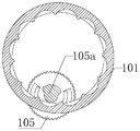
- FIG. 4c is a schematic cross-sectional view of the release handle in the released state from BB in FIG. 4b according to an embodiment of the present invention
- 4d is a schematic cross-sectional view of the release handle in the locked state from BB in FIG. 4b according to an embodiment of the present invention
- FIG. 4e is a partially enlarged schematic diagram of FIG. 4d according to an embodiment of the invention.
- FIG. 5 is a schematic diagram of an upper cover of a handle according to an embodiment of the invention.
- FIG. 6a is a schematic diagram of a dispersed reinforcing rib used for a handle lower cover according to an embodiment of the invention
- 6b is a schematic diagram of a metal support bar used for a handle lower cover according to another embodiment of the present invention.
- 6c is a schematic diagram of a honeycomb structure reinforcing rib of a handle lower cover according to another embodiment of the present invention.
- FIG. 7 is a schematic diagram of the lower cover of the handle and the rack after assembly according to an embodiment of the present invention.
- FIG. 8 is a partially enlarged schematic diagram of FIG. 7 according to an embodiment of the invention.
- FIG. 9 is a schematic cross-sectional view of a handle housing according to an embodiment of the invention.
- FIG. 10 is a partial cross-sectional schematic diagram of a medical implant delivery system according to an embodiment of the invention.
- FIG. 11 is a schematic cross-sectional view of a part including a bracket according to an embodiment of the present invention.
- FIG. 12 is a schematic cross-sectional view of an initial state of a medical implant delivery system according to an embodiment of the invention.
- FIG. 13 is a schematic cross-sectional view of a medical implant delivery system after being released by rotation according to an embodiment of the present invention
- FIG. 14 is a schematic cross-sectional view of the state of the maximum release stroke of the medical implant delivery system according to an embodiment of the present invention.
- 102-handle base 102b-ring support plate; 103-handle upper cover; 103a-handle upper cover reinforcement plate; 103b-handle upper cover reinforcement rib; 104-handle lower cover; 104a-handle lower cover reinforcement plate; 104b-reinforcement Rib; 11-handle shell; 11a-step; 11b-handle head; 11c-handle first lever; 11d-handle second lever; 105-release switch; 105a-cam; 105b-rotation limit stop; 105c-jump foot; 106-handle end cover;
- 20-rack 20-rack; 20a-teeth; 20b-rack interior; 20c-rack slide; 20d-rack reinforcement; 20e-rack end;
- 604-handle lower cover 604a-handle lower cover reinforcement plate; 604b-reinforcement rib;
- 704-handle lower cover 704a-handle lower cover reinforcement plate; 704b-metal support bar.
- distal means relatively distant from the patient's diseased area (area to be implanted) during surgical operation
- proximal means relatively close to the patient's diseased area (area to be implanted).
- This embodiment relates to a delivery system for medical implants, which can be adapted to the release of stents of different lengths through rotary release and/or axial pull release mode, and has a long release stroke, which can be achieved by axially pulling the release handle Quick release, especially to meet the requirements of longer specifications of accurate and quick release.
- FIG. 1 is a schematic structural diagram of a medical implant delivery system of this embodiment; as shown in FIG. 1, this embodiment provides a medical implant delivery system, including: a handle housing 11, a release handle 101, and a handle base 102 and a rack 20, the handle housing 11 has a hollow tubular shape and is provided with a bar-shaped opening along the axial direction thereof, the rack 20 is embedded in the handle housing 11 and is along the axial direction of the handle housing 11 And at least part of the teeth of the rack 20 protrudes from the strip-shaped opening, the handle base 102 is fixedly sleeved on the handle housing 11, and the release handle 101 is sleeved on the handle When the release handle 101 is rotated or axially pulled on the housing 11 and engaged with the teeth, the release handle 101 drives the rack to move to the distal end; wherein, when the release handle 101 is rotated, the The release handle 101 conforms to the handle base 102 and does not move in the axial direction.
- FIG. 2a is a schematic view of the release handle 101 and the handle base 102 of this embodiment after assembly;
- FIG. 2b is a schematic cross-sectional view from AA in FIG. 2a of this embodiment;
- FIG. 2c is a partially enlarged schematic view of FIG. 2b of this embodiment;
- FIG. 3 is a schematic diagram of the release switch of this embodiment.
- a release switch 105 that restricts the axial movement and circumferential rotation of the release handle 101 is provided between the release handle 101 and the handle base 102 to prevent The operator's misoperation.
- the release switch 105 is, for example, a turntable.
- the distal end of the release switch 105 is provided with a cam 105a.
- the proximal circumference of the release switch 105 is provided with a rotation limit stop 105b in the axial direction.
- the middle area of the release switch 105 is rotated toward A plurality of jumper legs 105c are circumferentially spaced on one side of the limit stop 105b.
- a distal opening of the handle base 102 is provided with a first opening 102a corresponding to the release switch 105.
- the release switch 105 is embedded in the first opening 102a, and the axes of the release switch 105 and the handle base 102 are arranged in parallel.
- the side of the handle base 102 near the first opening 102a is provided with a ring-shaped support plate 102b matching the release switch 105.
- the plane of the ring-shaped support plate 102b is perpendicular to the axis direction, and a plurality of jumper legs 105c of the release switch 105 are connected across the On the annular support plate 102b, so that the release switch 105 rotates steadily, the outer ring of the annular support plate 102b is within the range of the arc-shaped motion trajectory when the rotation limit stop 105b rotates with the release switch 105, that is, the annular shape of the annular support plate 102b The outer ring does not interfere with the rotation of the rotation stopper 105b.
- a first notch C1 and a second notch C2 are provided at the junction of the annular outer ring of the annular support plate 102b and the inner ring of the handle base 102.
- the rotation limit stop 105b rotates to At the first notch C1 or the second notch C2, the release switch stops rotating, and the rotation stroke of the release switch from the first notch C1 to the second notch C2 is less than or equal to 180°, up to the limit of rotation of the release switch 105 within the range of less than or equal to 180°
- the role of bits is provided at the junction of the annular outer ring of the annular support plate 102b and the inner ring of the handle base 102.
- the handle base 102 is sleeved and fixed on the handle housing 11.
- the ring-shaped handle base 102 is axially provided with a second opening 102 c corresponding to the strip-shaped opening on the handle housing 11.
- the diameter of the second opening 102 c The handle base 102 is penetrated upward so that the rack 20 can smoothly pass through the corresponding area of the handle base 102 when moving along the bar-shaped opening on the handle housing 11.
- FIG. 4a is a schematic perspective view of the release handle 101 and release switch 105 of this embodiment after assembly
- FIG. 4b is a schematic cross-sectional view of the release handle 101 and release switch 105 of this embodiment after assembly
- FIG. 4c is a release handle 101 of this embodiment 4b is a schematic cross-sectional view from BB in FIG. 4b in a released state
- FIG. 4d is a schematic cross-sectional view from BB in FIG. 4b when the release handle 101 of the embodiment is in a locked state
- FIG. 4e is a diagram in FIG. 4d of this embodiment A partially enlarged schematic.
- a plurality of limit grooves 101a matching the cam 105a on the release switch 105 are uniformly and continuously provided on the inner circumference of the proximal end of the release handle 101, each The limit groove 101a is provided with circumferential limit protrusions D on both sides in the circumferential direction. As shown in FIG. 4a, FIG. 4b, FIG. 4c, FIG. 4d and FIG. 4e, a plurality of limit grooves 101a matching the cam 105a on the release switch 105 are uniformly and continuously provided on the inner circumference of the proximal end of the release handle 101, each The limit groove 101a is provided with circumferential limit protrusions D on both sides in the circumferential direction. As shown in FIG.
- the cam 105a has a one-way limit protrusion B2, and a third notch corresponding to the one-way limit protrusion B2 is provided at a position of each limit groove 101a near one side circumferential limit protrusion D B1, when the release switch 105 is turned clockwise to turn the one-way limit projection B2 on the cam 105a to the third notch B1, in conjunction with FIG.
- the other side of the release switch 105 rotates the limit stop 105b just to rotate
- the release switch 105 cannot rotate clockwise; when the release switch 105 is turned counterclockwise, the cam 105a is rotated out of the limit groove 101a to unlock, and the release switch 105 can be unlocked counterclockwise
- the other side of the release switch 105 rotates the limit stop 105b to the second notch C2 limit.
- the release switch 105 can also be set to rotate clockwise, but not counterclockwise.
- the other side of the release switch 105 rotates the limit stop 105b only to rotate within the semicircular arc between the first notch C1 and the second notch C2, and the corresponding rotation angle (rotation stroke) of the release switch 105 is less than or equal to 180° .
- This design is because in actual operation, for example, when the release switch 105 is turned clockwise by 60°, the unlocked (released) target position can be reached, but the operator, such as a doctor, does not know which way to turn, and the opposite direction needs to be turned by 300° to unlock (released) )target location.
- the one-way rotation of the release switch 105 is realized and the rotation angle is less than
- the release handle 101 can be unlocked (released) within a range equal to 180° to shorten the rotation stroke, reduce redundant operations by an operator such as a doctor, and save precious time for surgery.
- FIG. 5 is a schematic view of the handle upper cover 103 of this embodiment;
- FIG. 6a is a schematic view of the present invention, the handle lower cover uses dispersed ribs 604b;
- FIG. 6b is another embodiment of the present invention, the handle lower cover uses metal
- FIG. 6c is a schematic diagram of a honeycomb structure reinforcing rib 104b for a handle lower cover according to yet another embodiment of the present invention.
- the handle housing 11 includes a handle upper cover and a handle lower cover.
- the total length of the handle structure itself is designed to be 340 mm to 350 mm, for example.
- the handle is prone to deformation under heavy use conditions, and the bending or torsion resistance is poor.
- the inventor tried to solve it by different methods. Among them, The upper cover of the handle and the lower cover of the handle have the same structure, and the lower cover of the handle is taken as an example. The inventor tried the first method, as shown in FIG.
- the inner side of the handle upper cover 103 is axially symmetrically provided with two handle upper cover reinforcing plates 103a perpendicular to the reference plane, wherein the bottom of the handle lower cover 104 is provided (when the semi-tubular opening is upward) And the plane tangent to the lower cover 104 of the handle is the reference plane.
- the handle upper cover reinforcing plate 103a extends to both ends of the handle upper cover 103 in the axial direction.
- the handle upper cover 103 is also provided with a handle upper cover reinforcing rib 103b, the handle upper cover reinforcing plate 103a is connected to the handle upper cover reinforcing rib 103b.
- the handle upper cover reinforcing rib 103b is a honeycomb structure.
- the inside of the handle lower cover 104 is axially symmetrically provided with two handle lower cover reinforcing plates 104a perpendicular to the reference plane. Specifically, the handle lower cover reinforcing plate 104a extends axially below the handle Cover 104 at both ends.
- the inside of the handle lower cover 104 is also provided with a handle lower cover reinforcing rib 104b.
- the handle lower cover reinforcing plate 104a is connected to the handle lower cover reinforcing rib 104b.
- the handle lower cover reinforcing rib 104b has a honeycomb structure.
- the honeycomb rib structure is cleverly applied to the handle upper cover 103 and the handle lower cover 104.
- the injection molding is simple and the cost is reasonable. It can greatly enhance the axial rigidity of the handle upper cover 103 and the handle lower cover 104.
- the handle assembly will not bend or twist.
- FIG. 7 is a schematic diagram of the lower handle cover 104 and the rack 20 of this embodiment after assembly;
- FIG. 8 is a partially enlarged schematic diagram of FIG. 7 of this embodiment;
- the handle housing 11 includes a handle upper cover 103 and a handle lower cover 104 that are detachably connected, and the handle upper cover 103 and the handle lower cover 104 are both semi-tubular.
- the plane at the bottom of the handle lower cover 104 (when the semi-tubular opening is up) and tangent to the handle lower cover 104 is the reference plane, and the axial direction of the handle housing 11 is the X direction, parallel
- the direction perpendicular to the X direction in the plane of the reference plane is the Y direction
- the direction perpendicular to the reference plane is the Z direction.
- the contact surface A on the side where the handle upper cover 103 and the handle lower cover 104 are engaged is parallel to the reference plane.
- the rack 20 is provided with teeth 20a partially protruding from the strip-shaped opening in the axial direction, and the rack 20 is provided with an axially penetrating rack inner cavity 20b, and the rack 20 is arranged in the axial direction (X direction)
- Two rack slideways 20c with a radial cross-sectional shape of "L" shape are symmetrically provided.
- One side of the "L" shaped rack slideway 20c is provided along the Y direction and the other side is provided along the Z direction.
- the rack 20 is provided with a plurality of rack reinforcement ribs 20d at intervals in the axial direction.
- the rack reinforcement ribs 20d have a plurality of rack reinforcement rib end faces 20e that are coplanar, and the planes where the plurality of rack reinforcement rib end faces 20e are located are parallel To the reference plane.
- the rack slideway 20c is matched with the handle lower cover reinforcement plate 104a. Specifically, the portion of the rack 20 located between the symmetrical rack slideways 20c snaps into the symmetrical handle lower cover reinforcement plate 104a.
- the plane of the slide rail 20c perpendicular to the reference plane fits with the plane of the handle lower cover reinforcing plate 104a perpendicular to the reference plane, so as to limit the rack 20 in the Y direction.
- the plane of the rack slideway 20c parallel to the reference plane coincides with the plane of the handle lower cover reinforcing plate 104a parallel to the reference plane, and a plurality of the rack reinforcing rib end faces 20e abut the handle upper cover reinforcing plate 103a Rely, to achieve the limit of the rack 20 in the Z direction.
- the rack slideway 20c and the handle lower cover reinforcing plate 104a fit in a plane parallel to and perpendicular to the reference plane, and the rack reinforcing rib end face 20e abuts against the handle upper cover reinforcing plate to achieve
- the limit of the rack 20 in the Y direction and the Z direction is ensured, and the rack 20 is smoothly moved in the axial direction (X direction) and is not derailed from the handle lower cover 104 and the handle upper cover 103 during the movement, which increases the transportation The stability of the system release process.
- the release track of the handle assembly of the medical implant delivery system is established through cooperation of the rack slideway 20c, the handle lower cover reinforcing plate 104a, and the handle upper cover reinforcing plate 103a.
- the handle lower cover reinforcing plate 104a extends in the axial direction to both ends of the handle lower cover 104, the handle lower cover reinforcing plate 104a and the handle lower cover reinforcing rib 104b are merged into one after being connected, and the handle upper cover reinforcing plate 103a is on the shaft Extend upwards to both ends of the handle upper cover 103, the handle upper cover reinforcing plate 103a and the handle upper cover reinforcing rib 103b are fused into one after being connected, the handle lower cover reinforcing plate 104a and the handle upper cover reinforcing plate 103a both establish release Track, and at the same time strengthen the corresponding handle lower cover 104 and handle upper cover 103.
- the rack rail 20c also establishes the release track while strengthening the strength of the rack 20 itself. Therefore, the handle lower cover reinforcement plate 104a, the handle upper cover reinforcement plate 103a, and the rack slide 20c all establish a release track while increasing the strength of the part itself.
- the handle housing 11 includes a handle head 11 b, a first handle 11 c and a second handle 11 d.
- the handle head portion 11b, the handle first lever portion 11c, and the handle second lever portion 11d are sequentially connected along the axial direction of the handle housing 11.
- the handle base 102 is fixedly sleeved on the connection between the first lever portion 11c of the handle and the second lever portion 11d of the handle.
- the diameter of the first lever portion 11c of the handle is larger than the diameter of the second lever portion 11d of the handle.
- the diameter of the first lever portion 11c of the handle may be equal to or smaller than the diameter of the second lever portion 11d of the handle.
- a step 11a is provided at the connection between the first lever portion 11c of the handle and the second lever portion 11d of the handle, and the handle base 102 is fixedly sleeved on the step 11a.
- the connection between the first lever portion 11c of the handle and the second lever portion 11d of the handle may be designed as other structures.
- the handle head 11b is in the shape of a pen head, the first handle part 11c and the second handle part 11d have a hollow tubular shape and a bar-shaped opening is opened along the axial direction, and the first handle part 11c and the second handle part 11d Internally connected.
- the rack 20 moves to the second rod portion 11d of the handle, the teeth 20a protrude from the bar-shaped opening, so that the release handle 101 is engaged with the teeth 20a.
- FIG. 10 is a partial cross-sectional schematic view of the medical implant delivery system of this embodiment
- FIG. 11 is a cross-sectional schematic view of the stent-containing part of this embodiment; as shown in FIGS. 1, 10, and 11, this embodiment also provides
- a medical implant delivery system includes a handle housing 11, a release handle 101, a handle base 102, a rack 20, and an outer sheath 304.
- the handle housing 11 is tubular and has a strip-shaped opening along its axial direction.
- the rack 20 is embedded in the handle housing 11, and at least part of the teeth of the rack 20 protrudes from the bar opening, and the handle base 102 is fixedly sleeved on the handle housing 11 ,
- the release handle 101 is sleeved on the handle housing 11 and meshes with the teeth, and when the release handle 101 is rotated or axially pulled, the release handle 101 drives the rack to move to the distal end;
- the release handle 101 When the release handle 101 is rotated, the release handle 101 conforms to the handle base 102 and does not move in the axial direction; the distal end of the outer sheath 304 is connected to the proximal end of the rack 20; rotation or shaft
- the release handle 101 drives the rack 20 to move to the distal end, so as to drive the outer sheath 304 to move to the distal end.
- the delivery system of the medical implant further includes an inner tube 301, the outer sheath 304 is sleeved outside the inner tube 301 and defines an accommodating space with the inner tube 301, and the container near the proximal end
- the mounting space is used for accommodating a bracket 303, which is generally tubular. The bracket is evenly compressed and loaded into the cavity between the inner tube 301 and the outer sheath 304.
- the proximal end of the rack 20 and the distal end of the outer sheath 304 are axially connected, specifically, the distal end of the outer sheath 304 and the outer
- the sheath connector 305 is fixedly connected, and the proximal end of the rack 20 is connected to the rack connector 306 through a sealing ring 307, and the rack connector 306 is screw-connected or slotted with the outer sheath connector 305, thereby realizing the rack 20 and the outer sheath 304 fixed connection.
- the fixed connection between the rack 20 and the outer sheath 304 can be glued, screwed, slot-restricted, and welded.
- Both the outer sheath connector 305 and the rack connector 306 are provided with axial through holes that can accommodate the inner tube 301.
- the rack 20 is provided with a rack inner cavity 20b that axially penetrates and houses the inner tube 301.
- FIGS. 12-14 are schematic cross-sectional views of the initial state of the medical implant delivery system of this embodiment.
- FIG. 13 is a schematic cross-sectional view of the medical implant delivery system of this embodiment after being released by rotation;
- FIG. 14 is a medical implant of this embodiment A schematic cross-sectional view of the state of the maximum release stroke of the inlet conveying system.
- the maximum release stroke of the medical implant delivery system of this embodiment can reach 280-300mm, which can be applied to the stent release of various lesion types, especially vascular lesions with long areas and complex paths .
- the medical implant delivery system of this embodiment releases the stent, it can be released in three ways.
- the medical implant delivery system has an initial state, in which the release handle 101 is attached to the handle base 102 and aligned via the release switch 105
- the release handle 101 is axially and circumferentially limited, and the distal end of the rack 20 is aligned with the distal end of the release handle 101.
- the initial state is directly held by toggle the release switch 105 and unlocked directly after holding the release handle 101 to the remote end Pull, the release handle 101 with the upper rack 20 moves synchronously and linearly to the distal end in the axial direction to achieve quick release of the bracket 303; it can also be released by rotating the release handle 101 in combination with the axial pull release handle 101, specifically, If the specification length of the bracket is very long, when the release handle 101 is not fully exposed after being released only by axially pulling back, the initial state is unlocked by toggling the release switch 105, and the original position is first (the release handle 101 is fitted to the handle base) 102 and do not move in the axial direction) rotate the release handle 101 as shown in FIG.
- the rack 20 on the 101 belt moves synchronously and linearly to the distal end in the axial direction, and the outer sheath 304 moves distally along the axial direction with the rack 20 until the stent is released, as shown in FIG. 14
- the proximal end of the rack 20 and the proximal end of the release handle 101 are both at the distal end of the handle housing 11 to obtain a maximum release stroke, which is, for example, 280 mm to 300 mm. It should be understood that the release stroke is the distance that the rack moves axially, that is, the distance that the outer sheath moves axially with the rack.
- the axis of the handle housing 11, the axis of the outer sheath 304 and the axis of the inner tube 301 are arranged in parallel, preferably, the axis of the handle housing 11, the axis of the outer sheath 304 and the inner tube 301
- the axes coincide.
- the inner tube 301 penetrates the handle housing 11 axially. Specifically, the inner tube 301 passes through the through hole of the outer sheath connector 305, the through hole of the rack connector 306, and the rack cavity of the rack 20 in sequence inside the handle housing 11 20b and fixed to the distal end of the handle cover 103 through the protective tube 402.
- the handle end cover 106 is fixed to the distal end of the handle housing 11.
- the inner tube 301 extends distally to the outside of the handle end cover 106 in the axial direction, and the distal end of the protection tube 402 is detachably connected to the inner tube tail connector 401.
- the inner tube end connector 401 and the protective tube 402 are detachably connected, for example, by screw fitting or taper fitting.
- the protective tube 402 is sleeved on the inner tube 301, and the proximal end of the protective tube 402 is located in the handle head 11b and connected to the spring 302. In this way, the inner tube 301, the spring 302, the protective tube 402, and the handle housing 11 are all fixedly connected to together.
- the inner tube 301 is thin and long, the inner tube 301 inside the handle housing 11 is supported and protected by the protective tube 402, and the inner tube 301 outside the handle housing 11 is supported and protected by the spring 302.
- the inner tube 301 extends axially through the handle housing 11 and extends axially proximally outside the handle housing 11 to form an inner tube extension.
- the proximal end of the inner tube extension is sleeved with a bracket 303 and the inner tube extension is close to
- a spring 302 is sleeved in an area where the bracket 303 is not sleeved on one side of the distal end, and the distal end of the spring 302 extends to the inside of the handle head 11b, and an outer sheath 304 is sleeved axially on the outer portion of the bracket 303 and the spring 302.
- the proximal end of 304 extends to the proximal end of the inner tube 301, the distal end of the outer sheath 304 extends to be fixedly connected to the outer sheath connector 305, the outer sheath 304 is used to protect the bracket 303, and is driven by the rack 20 to make the outer sheath 304 far
- the inner tube 301 is fixed in the handle shell 11
- the bracket 303 is sleeved on the fixed inner tube 301, so that the outer sheath 304 exposes the bracket 303 during the distal movement of the rack 20, that is, the bracket 303 released.
- There is a certain gap between the outer sheath 304 and the inner tube 301 for accommodating a variety of diseased blood vessels.
- the stent 303 is longer and the inner tube 301 is thinner.
- the stent 303 is not placed between the outer sheath 304 and the inner tube 301.
- a spring 302 is sleeved in the lumen on the side near the distal end, so that the piping system in the outer sheath 304 is more stable, and at the same time, the flexibility is increased.
- the proximal end of the bar-shaped opening of the handle housing 11 is provided with an infusion tube 51 and a one-way valve 52.
- the infusion tube 51 is an air exhaust channel of the medical implant delivery system, and the medical implant is emptied by injecting physiological saline into the infusion tube 51
- One-way valve 52 controls the one-way flow of physiological saline into the air in the object delivery system.
- the release handle when the release handle is rotated or axially pulled, the release handle drives the rack to move to the distal end, and the release or/and shaft is released by rotation
- the pull-to-pull release mode can adapt to the release of brackets with different specifications and lengths, and has a longer release stroke. Pulling the release handle axially can realize quick release, and in particular, can meet the requirements of longer specifications for accurate and quick release.
Landscapes
- Health & Medical Sciences (AREA)
- Engineering & Computer Science (AREA)
- Biomedical Technology (AREA)
- Heart & Thoracic Surgery (AREA)
- Oral & Maxillofacial Surgery (AREA)
- Transplantation (AREA)
- Cardiology (AREA)
- Vascular Medicine (AREA)
- Life Sciences & Earth Sciences (AREA)
- Animal Behavior & Ethology (AREA)
- General Health & Medical Sciences (AREA)
- Public Health (AREA)
- Veterinary Medicine (AREA)
- Prostheses (AREA)
- Media Introduction/Drainage Providing Device (AREA)
Abstract
一种医用植入物的输送系统,包括:手柄外壳(11)、释放手柄(101)、手柄座(102)以及齿条(20),手柄外壳(11)呈中空管状且沿其轴向开设有条形开口,齿条(20)嵌设在手柄外壳(11)内,并沿手柄外壳(11)的轴向设置,且齿条(20)至少有部分齿牙凸出于条形开口,手柄座(102)固定地套设于手柄外壳(11)上,释放手柄(101)套设于手柄外壳(11)上并与齿牙啮合,旋转或轴向拉动释放手柄(101)时,释放手柄(101)带动齿条(20)向远端移动。输送系统通过旋转释放或/和轴向拉动释放模式能适应不同规格长度的支架释放,有较长的释放行程,轴向拉动释放手柄可以实现快速释放,尤其能满足较长规格的支架准确快速释放。
Description
本发明涉及医用手术设备领域,尤其涉及一种医用植入物的输送系统。
目前心血管疾病已是人类健康的第一杀手。医用植入物例如支架被广泛应用于人体各种血管通路异常(血管瘤、夹层、栓塞、狭窄等等)的治疗当中。大部分支架通过微创伤的介入手术被植入到患者病变血管区域。通用步骤如下:首先将支架装载在输送系统里;然后将输送系统通过导丝/导管建立的血管通道送入到病变位置;接着通过输送系统上的释放装置将支架释放出来;最后支架留在体内,将输送系统撤出体外。
其中,支架释放步骤需要满足以下要求:对于规格较长的支架,需要释放时间尽量短,从而快速建立血流通道,减少周围血管或下肢血管的缺血时间,因此支架释放还需要兼顾较长的释放行程,且需要快速释放,现有市面上能满足上述性能要求的输送系统比较罕见。
发明内容
本发明的目的在于提供一种医用植入物的输送系统,以适应不同规格长度的支架释放,尤其能满足较长规格的支架准确快速释放。
为解决上述技术问题,本发明提供一种医用植入物的输送系统,包括:手柄外壳、释放手柄、手柄座以及齿条,所述手柄外壳呈中空管状且沿其轴向开设有条形开口,所述齿条嵌设在所述手柄外壳内,并沿所述手柄外壳的轴向设置,且所述齿条至少有部分齿牙凸出于所述条形开口,所述手柄座固定地套设于所述手柄外壳上,所述释放手柄套设于所述手柄外壳上并与所述齿牙啮合,旋转或轴向拉动所述释放手柄时所述释放手柄带动所述齿条向远端移动;其中,在旋转所述释放手柄时,所述释放手柄贴合所述手柄座且在轴向上相对于所述手柄座固定。
可选地,所述释放手柄和所述手柄座之间设置有限制所述释放手柄轴向 移动和周向旋转的释放开关。
可选地,所述手柄座的远端设置有第一开口,所述释放开关部分嵌设在所述第一开口中且所述释放开关的轴线与所述手柄外壳的轴线平行。
可选地,所述释放开关的远端设置有凸轮;所述释放手柄的近端内表面上设置有多个沿所述释放手柄的周向排布且与所述凸轮匹配的限位凹槽,每个所述限位凹槽沿周向的两侧设置有周向限位凸起。
可选地,所述手柄座上设置有与所述释放开关匹配的环形支撑板,所述环形支撑板的轴线与所述手柄外壳的轴线平行;所述释放开关的近端设置有至少两个跨接脚,每个所述跨接脚跨接在所述环形支撑板的内表面上。
可选地,所述环形支撑板的外表面与所述手柄座的内表面交界处形成有第一豁口和第二豁口,所述释放开关的近端设置有旋转限位挡片,所述释放开关顺时针或逆时针旋转时带动所述旋转限位挡片旋转至所述第一豁口或所述第二豁口处,所述旋转限位挡片卡入所述第一豁口或所述第二豁口中,以限制所述释放开关的旋转角度。
可选地,所述释放开关的旋转角度小于或等于180°。
可选地,所述凸轮上设置有单向限位凸起,每个所述限位凹槽上设置有与所述单向限位凸起对应的第三豁口,所述单向限位凸起和所述第三豁口配合以实现释放开关的单向旋转。
可选地,所述手柄外壳包括可拆卸连接的手柄上盖和手柄下盖。
可选地,所述手柄上盖的内侧沿其轴向设置有手柄上盖加强板,所述手柄下盖沿其轴向设置有手柄下盖加强板,所述齿条靠近所述手柄下盖的一侧设置有与所述手柄下盖加强板匹配的齿条滑道,所述齿条滑道沿所述手柄外壳的轴向延伸,所述齿条靠近所述手柄上盖的一侧与所述手柄上盖加强板相抵靠。
可选地,所述手柄上盖加强板、手柄下盖加强板以及齿条滑道的数量均为两个,每个所述齿条滑道径向截面形状为“L”形。
可选地,所述齿条上沿其轴向间隔设置有多个齿条加强筋。
可选地,所述手柄上盖内侧还设置有蜂窝状的手柄上盖加强筋,所述手 柄下盖内侧还设置有蜂窝状的手柄下盖加强筋。
可选地,所述手柄上盖加强筋与所述手柄上盖加强板连接;所述手柄下盖加强筋与所述手柄下盖加强板连接。
可选地,所述手柄外壳包括沿轴向依次连接的手柄头部、手柄第一杆部和手柄第二杆部,所述手柄座固定地套设于所述手柄第一杆部和所述手柄第二杆部的连接处。
可选地,所述手柄第一杆部的直径大于所述手柄第二杆部的直径,所述手柄第一杆部与所述手柄第二杆部的连接处设置有台阶,所述手柄座固定地套设于所述台阶处。
可选地,所述手柄头部呈笔头形状,所述手柄第一杆部和所述手柄第二杆部呈中空管状且沿其轴向开设有所述条形开口。
可选地,所述齿条设置有沿其轴向贯通的齿条内腔。
可选地,所述手柄座沿其轴向设置有与所述条形开口对应的第二开口。
可选地,还包括外鞘,所述外鞘的远端与所述齿条的近端连接;旋转或轴向拉动所述释放手柄时所述释放手柄带动所述齿条向远端移动,以带动所述外鞘向远端移动。
在本发明提供的医用植入物的输送系统中,旋转或轴向拉动所述释放手柄时所述释放手柄带动所述齿条向远端移动,通过旋转释放或/和轴向拉动释放模式能适应不同规格长度的支架释放,有较长的释放行程,轴向拉动所述释放手柄可以实现快速释放,尤其能满足较长规格的支架准确快速释放。
进一步的,本发明医用植入物的输送系统结构设计简单且巧妙,将蜂窝状结构用于手柄加强筋设计,不仅可以大大提高手柄的整体强度,而且成本合理、制作工艺简单。该输送系统可满足长规格支架的释放,可为临床医生提供更多的选择空间。
图1为本发明一实施例的医用植入物的输送系统的结构示意图;
图2a为本发明一实施例的释放手柄和手柄座装配后的示意图;
图2b为本发明一实施例的图2a中从AA处的剖面示意图;
图2c为本发明一实施例的图2b中的局部放大示意图;
图3为本发明一实施例的释放开关的示意图;
图4a为本发明一实施例的释放手柄和释放开关装配后的立体示意图;
图4b为本发明一实施例的释放手柄和释放开关装配后的剖面示意图;
图4c为本发明一实施例的释放手柄在释放状态时从图4b中BB处的剖面示意图;
图4d为本发明一实施例的释放手柄在锁止状态时从图4b中BB处的剖面示意图;
图4e为本发明一实施例的图4d中的局部放大示意图;
图5为本发明一实施例的手柄上盖的示意图;
图6a为本发明一实施例的手柄下盖采用分散的加强筋的示意图;
图6b为本发明另一实施例的手柄下盖采用金属支撑条的示意图;
图6c为本发明又一实施例的手柄下盖采用蜂窝结构的加强筋的示意图;
图7为本发明一实施例的手柄下盖和齿条装配后的示意图;
图8为本发明一实施例的图7的局部放大示意图;
图9为本发明一实施例的手柄外壳的剖面示意图;
图10为本发明一实施例的医用植入物的输送系统的局部剖面示意图;
图11为本发明一实施例的含支架部位的剖面示意图;
图12为本发明一实施例的医用植入物的输送系统的初始状态剖面示意图;
图13为本发明一实施例的医用植入物的输送系统的通过旋转释放后的剖面示意图;
图14为本发明一实施例的医用植入物的输送系统的最大释放行程状态的剖面示意图。
其中,附图标记如下:
101-释放手柄;101a-限位凹槽;
102-手柄座;102b-环形支撑板;103-手柄上盖;103a-手柄上盖加强板;103b-手柄上盖加强筋;104-手柄下盖;104a-手柄下盖加强板;104b-加强筋;11-手柄外壳;11a-台阶;11b-手柄头部;11c-手柄第一杆部;11d-手柄第二杆部;105-释放开关;105a-凸轮;105b-旋转限位挡片;105c-跨接脚;106-手柄端盖;
20-齿条;20a-齿牙;20b-齿条内腔;20c-齿条滑道;20d-齿条加强筋;20e-齿条加强筋端面;
301-内管;302-弹簧;303-支架;304-外鞘;305-外鞘连接件;306-齿条连接件;307-密封圈;
401-内管尾端连接件;402-保护管;51-输液管;52-单向阀。
604-手柄下盖;604a-手柄下盖加强板;604b-加强筋;
704-手柄下盖;704a-手柄下盖加强板;704b-金属支撑条。
以下结合附图和具体实施例对本发明提出的医用植入物的输送系统作进一步详细说明。根据下面说明和权利要求书,本发明的优点和特征将更清楚。需说明的是,附图均采用非常简化的形式且均使用非精准的比例,仅用以方便、明晰地辅助说明本发明实施例的目的。
本文所使用的“远端”的意思是手术操作时,相对地远离患者病变区域(待植入支架区域),“近端”的意思是相对地接近患者病变区域(待植入支架区域)。
本实施例涉及一种医用植入物的输送系统,通过旋转释放或/和轴向拉动释放模式能适应不同规格长度的支架释放,有较长的释放行程,轴向拉动所述释放手柄可以实现快速释放,尤其能满足较长规格的支架准确快速释放。
图1为本实施例的医用植入物的输送系统的结构示意图;如图1所示,本实施例提供一种医用植入物的输送系统,包括:手柄外壳11、释放手柄101、手柄座102以及齿条20,所述手柄外壳11呈中空管状且沿其轴向开设有条形开口,所述齿条20嵌设在所述手柄外壳11内,并沿所述手柄外壳11的轴向 设置,且所述齿条20至少有部分齿牙凸出于所述条形开口,所述手柄座102固定地套设于所述手柄外壳11上,所述释放手柄101套设于所述手柄外壳11上并与所述齿牙啮合,旋转或轴向拉动所述释放手柄101时,所述释放手柄101带动所述齿条向远端移动;其中,在旋转所述释放手柄101时,所述释放手柄101贴合所述手柄座102且在轴向上不移动。
图2a为本实施例的释放手柄101和手柄座102装配后示意图;图2b为本实施例的图2a中从AA处的剖面示意图;图2c为本实施例的图2b中的局部放大示意图;图3为本实施例的释放开关的示意图。
如图2a、图2b、图2c和图3所示,所述释放手柄101和所述手柄座102之间设置有限制所述释放手柄101轴向移动和周向旋转的释放开关105,以防止操作人员的误操作。
所述释放开关105例如为转盘,释放开关105的远端设置有凸轮105a,释放开关105的近端周圈上沿轴向设置有旋转限位挡片105b,释放开关105的中间区域朝向有旋转限位挡片105b的一侧周向间隔设置有若干跨接脚105c。
手柄座102的远端周圈上设置有与释放开关105对应的第一开口102a,释放开关105嵌入第一开口102a中,释放开关105和手柄座102的轴线平行设置。
手柄座102靠近第一开口102a的一侧设置有与释放开关105匹配的环形支撑板102b,所述环形支撑板102b所在平面垂直于轴线方向,释放开关105的若干跨接脚105c跨接在所述环形支撑板102b上,以使释放开关105稳固旋转,环形支撑板102b的外圈在旋转限位挡片105b随释放开关105转动时的弧形运动轨迹范围内,即环形支撑板102b的环形外圈不干涉旋转限位挡片105b的转动。环形支撑板102b的环形外圈与手柄座102的内圈交界处设置有第一豁口C1和第二豁口C2,释放开关105顺时针或逆时针旋转时,旋转限位挡片105b随之旋转至第一豁口C1或第二豁口C2处使释放开关停止旋转,从第一豁口C1至第二豁口C2释放开关的旋转行程小于等于180°,起到释放开关105在小于等于180°范围内旋转限位的作用。
结合图1所示,手柄座102套接固定在手柄外壳11上,环状的手柄座102轴向设置有与手柄外壳11上条形开口对应的第二开口102c,所述第二开口102c径向上贯通所述手柄座102以使齿条20沿手柄外壳11上条形开口移动时可顺利通过手柄座102对应区域。
图4a为本实施例的释放手柄101和释放开关105装配后的立体示意图;图4b为本实施例的释放手柄101和释放开关105装配后的剖面示意图;图4c为本实施例的释放手柄101在释放状态时从图4b中BB处的剖面示意图;图4d为本实施例的释放手柄101在锁止状态时从图4b中BB处的剖面示意图;图4e为本实施例的图4d中的局部放大示意图。
如图4a、图4b、图4c、图4d和图4e所示,释放手柄101近端内侧周圈上均匀连续设置有若干与释放开关105上的凸轮105a匹配的限位凹槽101a,每个所述限位凹槽101a沿周向的两侧设置有周向限位凸起D,如图4d所示,当拨动释放开关105使凸轮105a旋入释放手柄101上的限位凹槽101a时,轴向上因凸轮105a卡入限位凹槽101a实现释放手柄101的轴向限位,周向上旋转释放手柄101时周向限位凸起D被凸轮105a挡住,实现释放手柄101的周向限位(旋转限位)。如图4c所示,当拨动释放开关105使凸轮105a旋出释放手柄101上的限位凹槽101a时,释放手柄101在轴向和周向全部解锁(释放)。通过凸轮105a和限位凹槽101a的匹配实现释放手柄101的锁止(轴向限位和周向限位)或释放。
进一步的,凸轮105a具有单向限位凸起B2,每个限位凹槽101a靠近一侧周向限位凸起D的部位设置有与所述单向限位凸起B2对应的第三豁口B1,当顺时针拨动释放开关105使凸轮105a上的单向限位凸起B2转到第三豁口B1处的同时,结合图2c,释放开关105的另一面旋转限位挡片105b正好旋转到第一豁口C1限位,使释放开关105不能顺时针旋转;而当逆时针拨动释放开关105时,使凸轮105a从限位凹槽101a旋出解锁,可以实现释放开关105逆时针旋转解锁,相应的,释放开关105的另一面旋转限位挡片105b可转到第二豁口C2限位。同理,也可以设置释放开关105能顺时针旋转,不能逆时针旋转。释放开关105的另一面旋转限位挡片105b只能在第一豁口C1 和第二豁口C2之间的半圆弧范围内旋转,相应的释放开关105的旋转角度(旋转行程)小于等于180°。如此设计是因为,在实际操作中例如释放开关105顺时针转60°就可以到达解锁(释放)目标位置,但操作者例如医生不知往哪头转,相反方向需转300°才能达到解锁(释放)目标位置。通过凸轮105a的单向限位凸起B2和限位凹槽101a的第三豁口B1匹配并结合相应的旋转限位挡片105b的限位,实现释放开关105的单向旋转且在旋转角度小于等于180°范围内就可解锁(释放)释放手柄101,以缩短旋转行程,减少操作者例如医生多余的操作,节省手术宝贵的时间。
图5为本实施例的手柄上盖103的示意图;图6a为发明一本实施例的手柄下盖采用分散的加强筋604b的示意图;图6b为本发明另一实施例的手柄下盖采用金属支撑条704b的示意图;图6c为本发明又一实施例的手柄下盖采用蜂窝结构的加强筋104b的示意图。所述手柄外壳11包括手柄上盖和手柄下盖。
在研发本实施例的手柄上盖和手柄下盖的过程中,碰到如下问题,为满足超长的释放行程,手柄结构自身设计总长例如为340mm~350mm。这对于高分子材料的注塑件来说,面临两方面的挑战。一是注塑成型过程中容易发生翘曲,二是手柄在受力大的使用情况下容易发生变形,抗弯或者抗扭转能力差,在这种情况下,发明人尝试用不同方法解决,其中,手柄上盖和手柄下盖结构相同,以手柄下盖为例介绍。发明人尝试用第一种方法,如图6a所示,采用手柄下盖加强板604a结合手柄内侧分散的加强筋604b的方法,制作出实物模型后发现其抗扭转能力有限;于是,发明人继续尝试用第二种方法,如图6b所示,采用手柄下盖加强板704a结合金属支撑条704b的方法,具体为在注塑手柄下盖704过程中增加金属支撑条704b,但这种方法大大增加了注塑难度和注塑成本。考虑到第三种方法使用玻璃纤维增强注塑粒子,原材料成本较高。
在上述研究试验深入分析后,发明人采用手柄蜂窝结构增强设计,具体如图5和图6c所示。
如图5所示,手柄上盖103内侧轴向上对称设置有两个垂直于参考平面 的手柄上盖加强板103a,其中,设置过手柄下盖104的最底部(半管状开口向上状态时)且与手柄下盖104相切的平面为参考平面。具体的,手柄上盖加强板103a在轴向上延伸至手柄上盖103两端。手柄上盖103的内侧还设置有手柄上盖加强筋103b,所述手柄上盖加强板103a与所述手柄上盖加强筋103b连接,具体的,手柄上盖加强筋103b为蜂窝结构。
如图6c所示,手柄下盖104内侧轴向上对称设置有两个垂直于所述参考平面的手柄下盖加强板104a,具体的,手柄下盖加强板104a在轴向上延伸至手柄下盖104两端。手柄下盖104的内侧还设置有手柄下盖加强筋104b,所述手柄下盖加强板104a与所述手柄下盖加强筋104b连接,具体的,手柄下盖加强筋104b为蜂窝结构。
本实施例将蜂窝加强筋结构巧妙运用于手柄上盖103和手柄下盖104中,注塑成型简单,成本合理,可大大增强手柄上盖103和手柄下盖104的轴向刚度,在释放阻力大的情况下手柄组件也不会发生弯曲或扭转。
图7为本实施例的手柄下盖104和齿条20装配后的示意图;图8为本实施例的图7的局部放大示意图;
如图5~图8所示,所述手柄外壳11包括可拆卸连接的手柄上盖103和手柄下盖104,所述手柄上盖103和手柄下盖104均呈半管状。
为便于理解和方便描述,设置过手柄下盖104的最底部(半管状开口向上状态时)且与手柄下盖104相切的平面为参考平面,手柄外壳11的轴向方向为X方向,平行于所述参考平面的平面内与X方向垂直的方向为Y方向,与参考平面垂直的方向为Z方向。手柄上盖103和手柄下盖104扣合一侧的接触面A平行于所述参考平面。
所述齿条20沿轴向设置有部分凸出于所述条形开口的齿牙20a,所述齿条20上设置有轴向贯通的齿条内腔20b,所述齿条20沿轴向(X方向)对称设置有两个在径向截面形状为“L”形的齿条滑道20c,所述“L”形齿条滑道20c的一边沿Y方向设置,另一边沿Z方向设置。所述齿条20上沿轴向间隔设置有若干齿条加强筋20d,若干齿条加强筋20d具有共面的若干齿条加强筋端面20e,若干所述齿条加强筋端面20e所在的平面平行于所述参考平面。
齿条滑道20c与手柄下盖加强板104a相匹配设置,具体的,齿条20位于对称的齿条滑道20c之间的部分卡入对称的所述手柄下盖加强板104a之间,齿条滑道20c垂直于所述参考平面的平面与手柄下盖加强板104a垂直于所述参考平面的平面贴合,实现齿条20在Y方向的限位。
齿条滑道20c平行于所述参考平面的平面与手柄下盖加强板104a平行于所述参考平面的平面贴合,若干所述齿条加强筋端面20e与所述手柄上盖加强板103a相抵靠,实现齿条20在Z方向的限位。
如此一来,齿条滑道20c与手柄下盖加强板104a在与所述参考平面平行和垂直的平面内均贴合,齿条加强筋端面20e与所述手柄上盖加强板相抵靠,实现了齿条20在Y方向和Z方向的限位,保证了齿条20沿轴向(X方向)的平稳移动且在移动时与手柄下盖104和手柄上盖103都不脱轨,增加了输送系统释放过程的稳定性。
医用植入物输送系统的手柄组件的释放轨道是通过齿条滑道20c、手柄下盖加强板104a和手柄上盖加强板103a配合建立。手柄下盖加强板104a在轴向上延伸至手柄下盖104两端,所述手柄下盖加强板104a与所述手柄下盖加强筋104b连接后融合为一体,手柄上盖加强板103a在轴向上延伸至手柄上盖103两端,所述手柄上盖加强板103a与所述手柄上盖加强筋103b连接后融合为一体,手柄下盖加强板104a和手柄上盖加强板103a既建立释放轨道,同时又加强对应的手柄下盖104和手柄上盖103的强度。齿条滑道20c也是建立释放轨道的同时加强了齿条20自身的强度。因此,手柄下盖加强板104a、手柄上盖加强板103a和齿条滑道20c均是建立释放轨道的同时又增加零件自身强度。
图9为本实施例的手柄外壳的剖面示意图;如图1、图8和图9所示,手柄外壳11包括手柄头部11b、手柄第一杆部11c、手柄第二杆部11d。手柄头部11b、手柄第一杆部11c、手柄第二杆部11d沿手柄外壳11的轴向依次连接。手柄座102固定地套设于手柄第一杆部11c和手柄第二杆部11d的连接处。在本实施例中,手柄第一杆部11c的直径大于手柄第二杆部11d的直径。在其他实施例中,手柄第一杆部11c的直径可以等于或小于手柄第二杆部11d的直径。 在本实施例中,手柄第一杆部11c与所述手柄第二杆部11d的连接处设置有台阶11a,手柄座102固定地套设于台阶11a处。在其他实施例中,手柄第一杆部11c与所述手柄第二杆部11d的连接处还可以设计为其他结构。手柄头部11b呈笔头形状,手柄第一杆部11c和手柄第二杆部11d呈中空管状且沿其轴向开设有条形开口,且手柄第一杆部11c和手柄第二杆部11d的内部相连通。所述齿条20移动至所述手柄第二杆部11d时,所述齿牙20a凸出于所述条形开口,以使释放手柄101与齿牙20a啮合。
图10为本实施例的医用植入物的输送系统的局部剖面示意图;图11为本实施例的含支架部位的剖面示意图;如图1、图10和图11所示,本实施例还提供一种医用植入物输送系统,包括:手柄外壳11、释放手柄101、手柄座102、齿条20以及外鞘304,所述手柄外壳11呈管状且沿其轴向开设有条形开口,所述齿条20嵌设在所述手柄外壳11内,且所述齿条20至少有部分齿牙凸出于所述条形开口,所述手柄座102固定地套设于所述手柄外壳11上,所述释放手柄101套设于所述手柄外壳11上并与所述齿牙啮合,旋转或轴向拉动所述释放手柄101时所述释放手柄101带动所述齿条向远端移动;在旋转所述释放手柄101时,所述释放手柄101贴合所述手柄座102且在轴向上不移动;所述外鞘304的远端与所述齿条20的近端连接;旋转或轴向拉动所述释放手柄101时所述释放手柄101带动所述齿条20向远端移动,以带动所述外鞘304向远端移动。
所述医用植入物的输送系统还包括内管301,所述外鞘304套设于所述内管301外并与所述内管301共同限定一容置空间,靠近近端的所述容置空间用于容置一支架303,支架303通常为管状,支架被均匀压缩并装载在内管301与外鞘304之间的空腔内。
结合图9和图10所示,在所述手柄头部11b内,所述齿条20的近端与所述外鞘304的远端沿轴向连接,具体的,外鞘304远端与外鞘连接件305固定连接,齿条20近端通过密封圈307与齿条连接件306连接,齿条连接件306与外鞘连接件305螺纹连接或卡槽连接,从而实现齿条20与外鞘304的固定连接。应当理解,齿条20与外鞘304之间的固定连接可通过胶水粘接、 螺纹连接、卡槽限位连接以及焊接方式。外鞘连接件305和齿条连接件306均设置有可容纳内管301的轴向贯通孔。所述齿条20上设置有轴向贯通的容纳所述内管301的齿条内腔20b。
图12为本实施例的医用植入物输送系统的初始状态剖面示意图;图13为本实施例的医用植入物输送系统的通过旋转释放后的剖面示意图;图14为本实施例的医用植入物输送系统的最大释放行程状态的剖面示意图。如图12~图14所示,本实施例的医用植入物输送系统最大释放行程可达280~300mm,可适用于多种病变类型的支架释放,尤其是区域较长、路径复杂的血管病变。
本实施例的医用植入物输送系统释放支架时,可通过三种方式释放。
如图12、图1和图10所示,所述医用植入物输送系统具有初始状态,在所述初始状态时,所述释放手柄101与手柄座102贴合并通过所述释放开关105对所述释放手柄101轴向和周向限位,齿条20远端与释放手柄101远端对齐。
先握住手柄座102及手柄外壳11近端部分,可仅通过旋转释放手柄101释放,具体的,若支架的规格较短时,拨动释放开关105解锁,然后原位(释放手柄101贴合手柄座102且在轴向不移动)旋转释放手柄101,释放手柄101啮合齿条20传动,外鞘304随齿条20沿着轴向向远端移动,直至支架303释放(暴露);也可仅通过轴向拉动释放手柄101释放,具体的,若支架303的规格较长,需要实现快速释放,则所述初始状态通过拨动释放开关105解锁后直接握住释放手柄101向远端快速后拉,释放手柄101带上齿条20同步在轴向上直线向远端移动,以实现支架303的快速释放;还可通过旋转释放手柄101与轴向拉动释放手柄101组合方式释放,具体的,若支架的规格长度很长,在仅通过轴向后拉释放手柄101释放后还不能完全暴露出来时,所述初始状态通过拨动释放开关105解锁,先原位(释放手柄101贴合手柄座102且在轴向不移动)旋转释放手柄101,如图13所示,直至齿条20近端与释放手柄101近端对齐,然后轴向向远端拉动所述释放手柄101,所述释放手柄101带上所述齿条20同步在轴向上直线向远端移动,所述外鞘304随齿条20沿着轴向向远端移动,直至支架释放,如图14所示,最远可移动至所 述齿条20的近端和所述释放手柄101的近端均在手柄外壳11的远端,以获得最大释放行程,所述最大释放行程例如为280mm~300mm。应当理解所述释放行程为齿条轴向移动的距离,亦即外鞘随齿条轴向移动的距离。
如图11、图12和图1所示,手柄外壳11的轴线、外鞘304的轴线和内管301的轴线平行设置,优选地,手柄外壳11的轴线、外鞘304的轴线和内管301的轴线重合。内管301轴向贯穿手柄外壳11,具体的,内管301在手柄外壳11内部依次穿过外鞘连接件305的贯通孔、齿条连接件306的贯通孔和齿条20的齿条内腔20b并通过保护管402固定在手柄上盖103的远端。手柄端盖106固定在手柄外壳11的远端。内管301沿轴向向远端延伸至手柄端盖106外部,保护管402远端可拆卸连接有内管尾端连接件401。内管尾端连接件401与保护管402可拆卸连接,例如通过螺纹配合或锥面配合。如此一来,当支架303较长,释放行程较大时,齿条20移至手柄外壳11远端时,还可通过拆除内管尾段连接件,使齿条继续移到手柄外壳11外部,直至齿条近端移至手柄外壳远端,从而进一步加大了释放行程。
保护管402套设在内管301上,保护管402近端位于手柄头部11b内并与弹簧302连接,如此一来,内管301、弹簧302、保护管402和手柄外壳11均固定连接在一起。内管301又细又长,手柄外壳11内部的内管301通过保护管402支撑和保护,手柄外壳11外部的内管301通过弹簧302支撑和保护。
内管301轴向贯穿手柄外壳11,并在手柄外壳11外部沿轴向向近端延伸形成内管延伸部,内管延伸部靠近近端的一侧套设有支架303,内管延伸部靠近远端的一侧未套设支架303的区域内套设有弹簧302,弹簧302远端延伸至手柄头部11b内侧,支架303和弹簧302的外部沿轴向套设有外鞘304,外鞘304近端延伸至内管301近端,外鞘304远端延伸至与外鞘连接件305固定连接,外鞘304用于保护支架303,并通过齿条20的带动,使外鞘304向远端移动,内管301固定在手柄外壳11内,支架303套设于固定的内管301上不动,从而使外鞘304随齿条20向远端移动的过程中暴露出支架303,即将支架303释放。外鞘304和内管301之间有一定的间隙用于容纳多种病变血管的支架303,外鞘304较长,内管301较细,外鞘304和内管301之间不放置 支架303的靠近远端的一侧内腔内套设弹簧302,以使外鞘304内的管路系统更加稳固,同时增加了柔顺性。
所述手柄外壳11的条形开口近端设置有输液管51和单向阀52,输液管51是医用植入物输送系统的排空气通道,通过在输液管51内注入生理盐水排空医用植入物输送系统内的空气,单向阀52控制生理盐水单向流动。
综上所述,在本发明提供的医用植入物的输送系统中,旋转或轴向拉动所述释放手柄时所述释放手柄带动所述齿条向远端移动,通过旋转释放或/和轴向拉动释放模式能适应不同规格长度的支架释放,有较长的释放行程,轴向拉动所述释放手柄可以实现快速释放,尤其能满足较长规格的支架准确快速释放。
下列公开提供了用于实现本公开的不同特征的多种不同实施例。以下将描述组件和布置的特定实施例以简化本公开。当然,这些仅是实施例并且不旨在限制本发明。例如,在以下描述中,使用诸如“在…之下”、“在…下面”、“下面的”、“上面的”等空间术语,以容易描述附图中所示的一个部件和另一个部件的位置关系,除图中所示的方位之外,空间关系术语将包括使用或操作中的装置的各种不同的方位。装置可以以其他方式定位,例如旋转90度或在其他方位,并且通过在此使用的空间关系描述符进行相应的解释。
本说明书中各个实施例采用递进的方式描述,每个实施例重点说明的都是与其他实施例的不同之处,各个实施例之间相同相似部分互相参见即可。对于实施例公开的系统而言,由于与实施例公开的方法相对应,所以描述的比较简单,相关之处参见方法部分说明即可。
上述描述仅是对本发明较佳实施例的描述,并非对本发明范围的任何限定,本发明领域的普通技术人员根据上述揭示内容做的任何变更、修饰,均属于权利要求书的保护范围。
Claims (20)
- 一种医用植入物的输送系统,其特征在于,包括:手柄外壳、释放手柄、手柄座以及齿条,所述手柄外壳呈中空管状且沿其轴向开设有条形开口,所述齿条嵌设在所述手柄外壳内,并沿所述手柄外壳的轴向设置,且所述齿条至少有部分齿牙凸出于所述条形开口,所述手柄座固定地套设于所述手柄外壳上,所述释放手柄套设于所述手柄外壳上并与所述齿牙啮合,旋转或轴向拉动所述释放手柄时所述释放手柄带动所述齿条向远端移动;其中,在旋转所述释放手柄时,所述释放手柄贴合所述手柄座且在轴向上相对于所述手柄座固定。
- 如权利要求1所述的医用植入物的输送系统,其特征在于,所述释放手柄和所述手柄座之间设置有限制所述释放手柄轴向移动和周向旋转的释放开关。
- 如权利要求2所述的医用植入物的输送系统,其特征在于,所述手柄座的远端设置有第一开口,所述释放开关部分嵌设在所述第一开口中且所述释放开关的轴线与所述手柄外壳的轴线平行。
- 如权利要求2所述的医用植入物的输送系统,其特征在于,所述释放开关的远端设置有凸轮;所述释放手柄的近端内表面上设置有多个沿所述释放手柄的周向排布且与所述凸轮匹配的限位凹槽,每个所述限位凹槽沿周向的两侧设置有周向限位凸起。
- 如权利要求3所述的医用植入物的输送系统,其特征在于,所述手柄座上设置有与所述释放开关匹配的环形支撑板,所述环形支撑板的轴线与所述手柄外壳的轴线平行;所述释放开关的近端设置有至少两个跨接脚,每个所述跨接脚跨接在所述环形支撑板的内表面上。
- 如权利要求5所述的医用植入物的输送系统,其特征在于,所述环形支撑板的外表面与所述手柄座的内表面交界处形成有第一豁口和第二豁口,所述释放开关的近端设置有旋转限位挡片,所述释放开关顺时针或逆时针旋转时带动所述旋转限位挡片旋转至所述第一豁口或所述第二豁口处,所述旋 转限位挡片卡入所述第一豁口或所述第二豁口中,以限制所述释放开关的旋转角度。
- 如权利要求6所述的医用植入物的输送系统,其特征在于,所述释放开关的旋转角度小于或等于180°。
- 如权利要求4所述的医用植入物的输送系统,其特征在于,所述凸轮上设置有单向限位凸起,每个所述限位凹槽上设置有与所述单向限位凸起对应的第三豁口,所述单向限位凸起和所述第三豁口配合以实现释放开关的单向旋转。
- 如权利要求1所述的医用植入物的输送系统,其特征在于,所述手柄外壳包括可拆卸连接的手柄上盖和手柄下盖。
- 如权利要求9所述的医用植入物的输送系统,其特征在于,所述手柄上盖的内侧沿其轴向设置有手柄上盖加强板,所述手柄下盖沿其轴向设置有手柄下盖加强板,所述齿条靠近所述手柄下盖的一侧设置有与所述手柄下盖加强板匹配的齿条滑道,所述齿条滑道沿所述手柄外壳的轴向延伸,所述齿条靠近所述手柄上盖的一侧与所述手柄上盖加强板相抵靠。
- 如权利要求10所述的医用植入物的输送系统,其特征在于,所述手柄上盖加强板、手柄下盖加强板以及齿条滑道的数量均为两个,每个所述齿条滑道径向截面形状为“L”形。
- 如权利要求10所述的医用植入物的输送系统,其特征在于,所述齿条上沿其轴向间隔设置有多个齿条加强筋。
- 如权利要求10所述的医用植入物的输送系统,其特征在于,所述手柄上盖内侧还设置有蜂窝状的手柄上盖加强筋,所述手柄下盖内侧还设置有蜂窝状的手柄下盖加强筋。
- 如权利要求13所述的医用植入物的输送系统,其特征在于,所述手柄上盖加强筋与所述手柄上盖加强板连接;所述手柄下盖加强筋与所述手柄下盖加强板连接。
- 如权利要求1至14中任一项所述的医用植入物的输送系统,其特征在于,所述手柄外壳包括沿轴向依次连接的手柄头部、手柄第一杆部和手柄 第二杆部,所述手柄座固定地套设于所述手柄第一杆部和所述手柄第二杆部的连接处。
- 如权利要求15所述的医用植入物的输送系统,其特征在于,所述手柄第一杆部的直径大于所述手柄第二杆部的直径,所述手柄第一杆部与所述手柄第二杆部的连接处设置有台阶,所述手柄座固定地套设于所述台阶处。
- 如权利要求15所述的医用植入物的输送系统,其特征在于,所述手柄头部呈笔头形状,所述手柄第一杆部和所述手柄第二杆部呈中空管状且沿其轴向开设有所述条形开口。
- 如权利要求1至14中任一项所述的医用植入物的输送系统,其特征在于,所述齿条设置有沿其轴向贯通的齿条内腔。
- 如权利要求1至14中任一项所述的医用植入物的输送系统,其特征在于,所述手柄座沿其轴向设置有与所述条形开口对应的第二开口。
- 如权利要求1所述的医用植入物的输送系统,其特征在于,还包括外鞘,所述外鞘的远端与所述齿条的近端连接;旋转或轴向拉动所述释放手柄时所述释放手柄带动所述齿条向远端移动,以带动所述外鞘向远端移动。
Priority Applications (1)
| Application Number | Priority Date | Filing Date | Title |
|---|---|---|---|
| EP19902238.5A EP3903745B1 (en) | 2018-12-29 | 2019-11-05 | Delivery system for medical implant |
Applications Claiming Priority (2)
| Application Number | Priority Date | Filing Date | Title |
|---|---|---|---|
| CN201811647489.6A CN109481110B (zh) | 2018-12-29 | 2018-12-29 | 医用植入物的输送系统 |
| CN201811647489.6 | 2018-12-29 |
Publications (1)
| Publication Number | Publication Date |
|---|---|
| WO2020134593A1 true WO2020134593A1 (zh) | 2020-07-02 |
Family
ID=65713649
Family Applications (1)
| Application Number | Title | Priority Date | Filing Date |
|---|---|---|---|
| PCT/CN2019/115639 Ceased WO2020134593A1 (zh) | 2018-12-29 | 2019-11-05 | 医用植入物的输送系统 |
Country Status (3)
| Country | Link |
|---|---|
| EP (1) | EP3903745B1 (zh) |
| CN (2) | CN113693801B (zh) |
| WO (1) | WO2020134593A1 (zh) |
Cited By (1)
| Publication number | Priority date | Publication date | Assignee | Title |
|---|---|---|---|---|
| US20220226135A1 (en) * | 2021-01-21 | 2022-07-21 | Inspiremd Ltd. | Handle for two-stage deployment of a stent |
Families Citing this family (5)
| Publication number | Priority date | Publication date | Assignee | Title |
|---|---|---|---|---|
| CN113693801B (zh) * | 2018-12-29 | 2024-01-23 | 上海拓脉医疗科技有限公司 | 医用植入物的输送系统 |
| KR102244846B1 (ko) * | 2019-04-18 | 2021-04-28 | 주식회사 엠아이텍 | 스텐트 딜리버리 장치 |
| CN111110302B (zh) * | 2019-12-16 | 2021-06-25 | 先健科技(深圳)有限公司 | 输送系统 |
| CN112716666B (zh) * | 2021-01-22 | 2024-11-15 | 江苏暖阳医疗器械有限公司 | 一种手柄式支架系统 |
| CN114533356B (zh) * | 2022-02-25 | 2024-03-12 | 江苏唯德康医疗科技有限公司 | 一种卡扣限位结构及使用其的支架置入器 |
Citations (10)
| Publication number | Priority date | Publication date | Assignee | Title |
|---|---|---|---|---|
| US20050027305A1 (en) * | 2002-04-23 | 2005-02-03 | Brian Shiu | Integrated mechanical handle with quick slide mechanism |
| CN102892389A (zh) * | 2010-05-14 | 2013-01-23 | 美敦力瓦斯科尔勒公司 | 用于假体递送系统的导管手柄 |
| CN103505311A (zh) * | 2013-08-08 | 2014-01-15 | 浙江归创医疗器械有限公司 | 植入医疗器械输送装置及其控制方法 |
| CN103655004A (zh) * | 2012-09-21 | 2014-03-26 | 上海微创医疗器械(集团)有限公司 | 植入体输送系统 |
| CN105209105A (zh) * | 2013-03-15 | 2015-12-30 | 波顿医疗公司 | 止血阀和输送系统 |
| CN106730246A (zh) * | 2017-01-16 | 2017-05-31 | 杭州唯强医疗科技有限公司 | 适合左手操作的可调弯导管 |
| US20180051836A1 (en) * | 2015-04-16 | 2018-02-22 | Krzysztof Jan Wajnikonis | Enhancements of mechanical connector technology |
| CN207286184U (zh) * | 2016-12-26 | 2018-05-01 | 先健科技(深圳)有限公司 | 输送系统 |
| CN109481110A (zh) * | 2018-12-29 | 2019-03-19 | 上海微创心脉医疗科技股份有限公司 | 医用植入物的输送系统 |
| CN209661891U (zh) * | 2018-12-29 | 2019-11-22 | 上海微创心脉医疗科技股份有限公司 | 医用植入物的输送系统 |
Family Cites Families (15)
| Publication number | Priority date | Publication date | Assignee | Title |
|---|---|---|---|---|
| ATE538737T1 (de) * | 2005-04-15 | 2012-01-15 | Cook Medical Technologies Llc | Leitungsextraktionsvorrichtung |
| JP6163478B2 (ja) * | 2012-02-15 | 2017-07-12 | テルモ株式会社 | ステントデリバリーシステム |
| WO2013125107A1 (ja) * | 2012-02-24 | 2013-08-29 | テルモ株式会社 | ステントグラフトデリバリー装置 |
| US9918737B2 (en) * | 2013-03-15 | 2018-03-20 | The Spectranetics Corporation | Medical device for removing an implanted object |
| US9439751B2 (en) * | 2013-03-15 | 2016-09-13 | Bolton Medical, Inc. | Hemostasis valve and delivery systems |
| US9849016B2 (en) * | 2014-04-04 | 2017-12-26 | W. L. Gore & Associates, Inc. | Method of manufacturing a deployment handle of a medical device deployment system |
| US10292850B2 (en) * | 2014-11-04 | 2019-05-21 | Cook Medical Technologies Llc | Deployment handle for a prosthesis delivery device |
| EP3284446B1 (en) * | 2014-12-04 | 2018-12-19 | Cook Medical Technologies LLC | Delivery device handle assembly for the sequential deployment of a prosthesis |
| US9192500B1 (en) * | 2015-01-29 | 2015-11-24 | Intact Vascular, Inc. | Delivery device and method of delivery |
| US9456914B2 (en) * | 2015-01-29 | 2016-10-04 | Intact Vascular, Inc. | Delivery device and method of delivery |
| EP3291869A4 (en) * | 2015-05-06 | 2019-10-23 | Imricor Medical Systems, Inc. | SLIDING VALVE ADAPTER FOR ORIENTABLE SHEATH |
| KR20230104750A (ko) * | 2015-12-16 | 2023-07-10 | 콘메드 코포레이션 | 매듭없는 봉합사 앵커 및 전개 장치 |
| JP6602491B2 (ja) * | 2015-12-23 | 2019-11-06 | シャンハイ マイクロポート エンドヴァスキュラー メドテック カンパニー リミテッド | ステント送達システム、そのアセンブリ、およびその使用方法 |
| CN106580375B (zh) * | 2016-12-15 | 2020-09-22 | 杭州启明医疗器械股份有限公司 | 一种导丝调节器以及输送系统控制手柄 |
| CN108236533B (zh) * | 2016-12-26 | 2024-09-24 | 先健科技(深圳)有限公司 | 输送系统 |
-
2018
- 2018-12-29 CN CN202111013348.0A patent/CN113693801B/zh active Active
- 2018-12-29 CN CN201811647489.6A patent/CN109481110B/zh active Active
-
2019
- 2019-11-05 WO PCT/CN2019/115639 patent/WO2020134593A1/zh not_active Ceased
- 2019-11-05 EP EP19902238.5A patent/EP3903745B1/en active Active
Patent Citations (10)
| Publication number | Priority date | Publication date | Assignee | Title |
|---|---|---|---|---|
| US20050027305A1 (en) * | 2002-04-23 | 2005-02-03 | Brian Shiu | Integrated mechanical handle with quick slide mechanism |
| CN102892389A (zh) * | 2010-05-14 | 2013-01-23 | 美敦力瓦斯科尔勒公司 | 用于假体递送系统的导管手柄 |
| CN103655004A (zh) * | 2012-09-21 | 2014-03-26 | 上海微创医疗器械(集团)有限公司 | 植入体输送系统 |
| CN105209105A (zh) * | 2013-03-15 | 2015-12-30 | 波顿医疗公司 | 止血阀和输送系统 |
| CN103505311A (zh) * | 2013-08-08 | 2014-01-15 | 浙江归创医疗器械有限公司 | 植入医疗器械输送装置及其控制方法 |
| US20180051836A1 (en) * | 2015-04-16 | 2018-02-22 | Krzysztof Jan Wajnikonis | Enhancements of mechanical connector technology |
| CN207286184U (zh) * | 2016-12-26 | 2018-05-01 | 先健科技(深圳)有限公司 | 输送系统 |
| CN106730246A (zh) * | 2017-01-16 | 2017-05-31 | 杭州唯强医疗科技有限公司 | 适合左手操作的可调弯导管 |
| CN109481110A (zh) * | 2018-12-29 | 2019-03-19 | 上海微创心脉医疗科技股份有限公司 | 医用植入物的输送系统 |
| CN209661891U (zh) * | 2018-12-29 | 2019-11-22 | 上海微创心脉医疗科技股份有限公司 | 医用植入物的输送系统 |
Non-Patent Citations (1)
| Title |
|---|
| See also references of EP3903745A4 * |
Cited By (3)
| Publication number | Priority date | Publication date | Assignee | Title |
|---|---|---|---|---|
| US20220226135A1 (en) * | 2021-01-21 | 2022-07-21 | Inspiremd Ltd. | Handle for two-stage deployment of a stent |
| JP2022112482A (ja) * | 2021-01-21 | 2022-08-02 | インスパイアエムディー, リミテッド | ステントの2段階展開用ハンドル |
| US11839561B2 (en) * | 2021-01-21 | 2023-12-12 | Inspire M.D Ltd. | Handle for two-stage deployment of a stent |
Also Published As
| Publication number | Publication date |
|---|---|
| EP3903745B1 (en) | 2023-04-19 |
| CN113693801B (zh) | 2024-01-23 |
| CN113693801A (zh) | 2021-11-26 |
| EP3903745A1 (en) | 2021-11-03 |
| CN109481110B (zh) | 2024-02-02 |
| EP3903745A4 (en) | 2022-02-23 |
| CN109481110A (zh) | 2019-03-19 |
Similar Documents
| Publication | Publication Date | Title |
|---|---|---|
| CN109481110B (zh) | 医用植入物的输送系统 | |
| CN106730246B (zh) | 适合左手操作的可调弯导管 | |
| US7588555B2 (en) | Bi-directional catheter assembly and method therefor | |
| US9011380B2 (en) | Catheter for introduction of medications to the tissues of a heart or other organ | |
| WO2020134024A1 (zh) | 用于输送器的止缩装置及其输送器 | |
| KR102665074B1 (ko) | 이식물 이송 시스템 | |
| CN108236532B (zh) | 支架输送器 | |
| CN113229999A (zh) | 一种用于控制分流装置释放的组件及输送器 | |
| CN110638488A (zh) | 连接可靠的植入物推送装置及植入物输送系统 | |
| US8986225B2 (en) | Guidewire | |
| US20150080792A1 (en) | Operating member | |
| WO2020068841A1 (en) | Apparatus and method for septal punch | |
| CN204352347U (zh) | 分段式柔性渐变血管微导管 | |
| CN110638489A (zh) | 快速释放的植入物推送装置及植入物输送系统 | |
| CN112353537A (zh) | 一种带有锁定机构的输送系统 | |
| CN204352348U (zh) | 一体式柔性渐变血管微导管 | |
| CN221732047U (zh) | 一种导丝固定夹持组件及介入器械输送装置 | |
| CN206809529U (zh) | 适合左手操作的可调弯导管 | |
| CN220124807U (zh) | 一种介入手术机器人 | |
| CN110420376B (zh) | 药物球囊导管用盘管及药物球囊导管装置 | |
| CN112971900A (zh) | 输送装置 | |
| CN216676049U (zh) | 一种输送器 | |
| CN222917943U (zh) | 鞘管结构 | |
| CN120227224B (zh) | 输送器后释放组件及输送器 | |
| CN222055471U (zh) | 一种医疗器械及其医疗器械系统 |
Legal Events
| Date | Code | Title | Description |
|---|---|---|---|
| 121 | Ep: the epo has been informed by wipo that ep was designated in this application |
Ref document number: 19902238 Country of ref document: EP Kind code of ref document: A1 |
|
| NENP | Non-entry into the national phase |
Ref country code: DE |
|
| ENP | Entry into the national phase |
Ref document number: 2019902238 Country of ref document: EP Effective date: 20210729 |