WO2020136806A1 - 暖房システム - Google Patents
暖房システム Download PDFInfo
- Publication number
- WO2020136806A1 WO2020136806A1 PCT/JP2018/048154 JP2018048154W WO2020136806A1 WO 2020136806 A1 WO2020136806 A1 WO 2020136806A1 JP 2018048154 W JP2018048154 W JP 2018048154W WO 2020136806 A1 WO2020136806 A1 WO 2020136806A1
- Authority
- WO
- WIPO (PCT)
- Prior art keywords
- temperature
- heat medium
- heat
- flow rate
- hot water
- Prior art date
- Legal status (The legal status is an assumption and is not a legal conclusion. Google has not performed a legal analysis and makes no representation as to the accuracy of the status listed.)
- Ceased
Links
Images



Classifications
-
- F—MECHANICAL ENGINEERING; LIGHTING; HEATING; WEAPONS; BLASTING
- F24—HEATING; RANGES; VENTILATING
- F24D—DOMESTIC- OR SPACE-HEATING SYSTEMS, e.g. CENTRAL HEATING SYSTEMS; DOMESTIC HOT-WATER SUPPLY SYSTEMS; ELEMENTS OR COMPONENTS THEREFOR
- F24D3/00—Hot-water central heating systems
- F24D3/18—Hot-water central heating systems using heat pumps
-
- F—MECHANICAL ENGINEERING; LIGHTING; HEATING; WEAPONS; BLASTING
- F24—HEATING; RANGES; VENTILATING
- F24D—DOMESTIC- OR SPACE-HEATING SYSTEMS, e.g. CENTRAL HEATING SYSTEMS; DOMESTIC HOT-WATER SUPPLY SYSTEMS; ELEMENTS OR COMPONENTS THEREFOR
- F24D19/00—Details
- F24D19/10—Arrangement or mounting of control or safety devices
- F24D19/1006—Arrangement or mounting of control or safety devices for water heating systems
- F24D19/1009—Arrangement or mounting of control or safety devices for water heating systems for central heating
- F24D19/1012—Arrangement or mounting of control or safety devices for water heating systems for central heating by regulating the speed of a pump
-
- F—MECHANICAL ENGINEERING; LIGHTING; HEATING; WEAPONS; BLASTING
- F24—HEATING; RANGES; VENTILATING
- F24D—DOMESTIC- OR SPACE-HEATING SYSTEMS, e.g. CENTRAL HEATING SYSTEMS; DOMESTIC HOT-WATER SUPPLY SYSTEMS; ELEMENTS OR COMPONENTS THEREFOR
- F24D19/00—Details
- F24D19/10—Arrangement or mounting of control or safety devices
- F24D19/1006—Arrangement or mounting of control or safety devices for water heating systems
- F24D19/1009—Arrangement or mounting of control or safety devices for water heating systems for central heating
- F24D19/1039—Arrangement or mounting of control or safety devices for water heating systems for central heating the system uses a heat pump
-
- F—MECHANICAL ENGINEERING; LIGHTING; HEATING; WEAPONS; BLASTING
- F24—HEATING; RANGES; VENTILATING
- F24H—FLUID HEATERS, e.g. WATER OR AIR HEATERS, HAVING HEAT-GENERATING MEANS, e.g. HEAT PUMPS, IN GENERAL
- F24H15/00—Control of fluid heaters
- F24H15/10—Control of fluid heaters characterised by the purpose of the control
- F24H15/144—Measuring or calculating energy consumption
-
- F—MECHANICAL ENGINEERING; LIGHTING; HEATING; WEAPONS; BLASTING
- F24—HEATING; RANGES; VENTILATING
- F24H—FLUID HEATERS, e.g. WATER OR AIR HEATERS, HAVING HEAT-GENERATING MEANS, e.g. HEAT PUMPS, IN GENERAL
- F24H15/00—Control of fluid heaters
- F24H15/20—Control of fluid heaters characterised by control inputs
- F24H15/212—Temperature of the water
- F24H15/219—Temperature of the water after heating
-
- F—MECHANICAL ENGINEERING; LIGHTING; HEATING; WEAPONS; BLASTING
- F24—HEATING; RANGES; VENTILATING
- F24H—FLUID HEATERS, e.g. WATER OR AIR HEATERS, HAVING HEAT-GENERATING MEANS, e.g. HEAT PUMPS, IN GENERAL
- F24H15/00—Control of fluid heaters
- F24H15/20—Control of fluid heaters characterised by control inputs
- F24H15/238—Flow rate
-
- F—MECHANICAL ENGINEERING; LIGHTING; HEATING; WEAPONS; BLASTING
- F24—HEATING; RANGES; VENTILATING
- F24H—FLUID HEATERS, e.g. WATER OR AIR HEATERS, HAVING HEAT-GENERATING MEANS, e.g. HEAT PUMPS, IN GENERAL
- F24H15/00—Control of fluid heaters
- F24H15/20—Control of fluid heaters characterised by control inputs
- F24H15/254—Room temperature
-
- F—MECHANICAL ENGINEERING; LIGHTING; HEATING; WEAPONS; BLASTING
- F24—HEATING; RANGES; VENTILATING
- F24H—FLUID HEATERS, e.g. WATER OR AIR HEATERS, HAVING HEAT-GENERATING MEANS, e.g. HEAT PUMPS, IN GENERAL
- F24H15/00—Control of fluid heaters
- F24H15/20—Control of fluid heaters characterised by control inputs
- F24H15/281—Input from user
-
- F—MECHANICAL ENGINEERING; LIGHTING; HEATING; WEAPONS; BLASTING
- F24—HEATING; RANGES; VENTILATING
- F24H—FLUID HEATERS, e.g. WATER OR AIR HEATERS, HAVING HEAT-GENERATING MEANS, e.g. HEAT PUMPS, IN GENERAL
- F24H15/00—Control of fluid heaters
- F24H15/30—Control of fluid heaters characterised by control outputs; characterised by the components to be controlled
- F24H15/375—Control of heat pumps
-
- F—MECHANICAL ENGINEERING; LIGHTING; HEATING; WEAPONS; BLASTING
- F24—HEATING; RANGES; VENTILATING
- F24H—FLUID HEATERS, e.g. WATER OR AIR HEATERS, HAVING HEAT-GENERATING MEANS, e.g. HEAT PUMPS, IN GENERAL
- F24H15/00—Control of fluid heaters
- F24H15/30—Control of fluid heaters characterised by control outputs; characterised by the components to be controlled
- F24H15/375—Control of heat pumps
- F24H15/38—Control of compressors of heat pumps
-
- F—MECHANICAL ENGINEERING; LIGHTING; HEATING; WEAPONS; BLASTING
- F24—HEATING; RANGES; VENTILATING
- F24H—FLUID HEATERS, e.g. WATER OR AIR HEATERS, HAVING HEAT-GENERATING MEANS, e.g. HEAT PUMPS, IN GENERAL
- F24H15/00—Control of fluid heaters
- F24H15/30—Control of fluid heaters characterised by control outputs; characterised by the components to be controlled
- F24H15/375—Control of heat pumps
- F24H15/385—Control of expansion valves of heat pumps
-
- F—MECHANICAL ENGINEERING; LIGHTING; HEATING; WEAPONS; BLASTING
- F24—HEATING; RANGES; VENTILATING
- F24D—DOMESTIC- OR SPACE-HEATING SYSTEMS, e.g. CENTRAL HEATING SYSTEMS; DOMESTIC HOT-WATER SUPPLY SYSTEMS; ELEMENTS OR COMPONENTS THEREFOR
- F24D2200/00—Heat sources or energy sources
- F24D2200/12—Heat pump
- F24D2200/123—Compression type heat pumps
-
- Y—GENERAL TAGGING OF NEW TECHNOLOGICAL DEVELOPMENTS; GENERAL TAGGING OF CROSS-SECTIONAL TECHNOLOGIES SPANNING OVER SEVERAL SECTIONS OF THE IPC; TECHNICAL SUBJECTS COVERED BY FORMER USPC CROSS-REFERENCE ART COLLECTIONS [XRACs] AND DIGESTS
- Y02—TECHNOLOGIES OR APPLICATIONS FOR MITIGATION OR ADAPTATION AGAINST CLIMATE CHANGE
- Y02B—CLIMATE CHANGE MITIGATION TECHNOLOGIES RELATED TO BUILDINGS, e.g. HOUSING, HOUSE APPLIANCES OR RELATED END-USER APPLICATIONS
- Y02B30/00—Energy efficient heating, ventilation or air conditioning [HVAC]
- Y02B30/12—Hot water central heating systems using heat pumps
-
- Y—GENERAL TAGGING OF NEW TECHNOLOGICAL DEVELOPMENTS; GENERAL TAGGING OF CROSS-SECTIONAL TECHNOLOGIES SPANNING OVER SEVERAL SECTIONS OF THE IPC; TECHNICAL SUBJECTS COVERED BY FORMER USPC CROSS-REFERENCE ART COLLECTIONS [XRACs] AND DIGESTS
- Y02—TECHNOLOGIES OR APPLICATIONS FOR MITIGATION OR ADAPTATION AGAINST CLIMATE CHANGE
- Y02B—CLIMATE CHANGE MITIGATION TECHNOLOGIES RELATED TO BUILDINGS, e.g. HOUSING, HOUSE APPLIANCES OR RELATED END-USER APPLICATIONS
- Y02B30/00—Energy efficient heating, ventilation or air conditioning [HVAC]
- Y02B30/70—Efficient control or regulation technologies, e.g. for control of refrigerant flow, motor or heating
Definitions
- the present invention relates to a heating system for heating a target space by circulating high-temperature water. In particular, it relates to improving efficiency.
- a hot water heating system for heating warm water or the like to a heating terminal such as a radiator, floor heating, or a fan coil unit to heat a room which is an air-conditioned space.
- a heating terminal such as a radiator, floor heating, or a fan coil unit
- the fluid passed through the heating terminal is water.
- the heat pump type hot water heating system uses a heat pump device that uses heat obtained from a heat source such as air, water, or the ground, as a heating device that heats water.
- a heat pump device, a heating terminal, and a circulation pump are connected by piping to form a hot water flow path, and the circulation pump is driven to circulate water to supply heat to the heating terminal.
- the forward hot water temperature which is the temperature of the water flowing from the heat pump device to the heating terminal, is controlled according to the difference between the room temperature, which is the room temperature, and the set room temperature, and it is necessary to maintain the room temperature. Supply heat.
- the outgoing hot water temperature is controlled so as to be the target outgoing hot water temperature determined based on the room temperature. For example, if the room temperature is lower than the set room temperature, the hot water temperature is increased to increase the amount of heat supplied, and if the room temperature is high, the hot water temperature is decreased to decrease the amount of heat supplied.
- the energy efficiency (COP: Coefficient of Performance) in the heat pump device that heats water decreases as the condensing temperature in the refrigeration cycle rises as the returning hot water temperature rises.
- the heat pump type heating system in order to avoid a decrease in COP in the heat pump device, which is the heating device, set target values for both the outgoing hot water temperature and the returning hot water temperature. Then, after the behavior of the outgoing hot water temperature is stabilized, the rotation speed of the circulation pump is controlled so that the return hot water temperature becomes the target return hot water temperature. Specifically, when the return warm water temperature is higher than the target return warm water temperature, the rotation speed of the circulation pump is reduced, and when the return warm water temperature is lower than the target return warm water temperature, the rotation speed of the circulation pump is increased (for example, , Patent Document 1).
- the target return hot water temperature is set, for example, by the user using a remote controller, or is preferably set to 34° C. to 45° C., more preferably 34° C. to 36° C.
- a heating system in which a flow rate control valve is provided in each heating terminal, the opening degree of the flow rate control valve which becomes an appropriate flow rate in the multi-system simultaneous operation is obtained during a trial operation, and the data of each opening degree is stored as an opening degree setting table.
- the opening degree setting table For example, refer to Patent Document 2. Then, based on the data of the opening degree setting table, the flow rate of water passing through the heating terminal is adjusted so that the return temperature becomes an appropriate low temperature at which the efficiency of the heat source device does not decrease.
- JP 2012-163275 A JP, 2006-284141, A
- the hot water flow rate is indirectly controlled by controlling the return hot water temperature to the target return hot water temperature.
- the reference value is only shown as a guideline for determining the target return hot water temperature.
- the flow rate is adjusted so that the return temperature becomes an appropriate low temperature at which the efficiency of the heat source device does not decrease.
- the heat radiation limit of the heating terminal is not taken into consideration when obtaining the appropriate low temperature limit point and the return temperature and flow rate setting value at that time from the trial run. Therefore, there is a possibility that operation with a high COP cannot be performed according to the setting environment of the heating system including the heating terminal.
- the present invention has an object to obtain a heating system capable of operating with a high COP in order to solve the above problems.
- the heating system of the present invention circulates the heat medium by pipe-connecting a heating terminal for exchanging heat between the air in the air-conditioned space and the heat medium, a circulation pump for applying pressure to the heat medium, and a heating device for heating the heat medium.
- a forward temperature sensor that constitutes the heat medium flow path and detects a forward heat medium temperature that is the temperature of the heat medium that flows from the heating device to the heating terminal, and a return heat medium temperature that is the temperature of the heat medium that flows from the heating terminal to the heating device.
- a return temperature sensor for detecting the temperature a room temperature sensor for detecting the room temperature that is the temperature in the air-conditioned space, and a control device for controlling the heating device and the circulation pump. The number of revolutions of the circulation pump is controlled based on the difference and the deviation between the forward heat medium temperature and the set target forward heat medium temperature.
- the control device controls the circulation pump based on the comparison between the temperature difference between the return hot water temperature and the room temperature and the heat radiation limit temperature difference and the deviation between the forward hot water temperature and the target forward hot water temperature, and the hot water The flow rate was controlled. Therefore, the heating device can be operated with a high COP in accordance with the heat radiation characteristics of the heating terminal that differ depending on the object to be air-conditioned.
- Embodiment 1. 1 is a diagram showing a configuration example of a heating system according to Embodiment 1 of the present invention.
- a heat pump type hot water heating system will be described.
- the heat pump hot water heating system according to the first embodiment includes a heat pump device 1, a circulation pump 7, and a heating terminal 8.
- the heat pump device 1 is a heating device that heats the water flowing through the hot water flow path.
- water is used as a heat medium that is a medium that conveys heat.
- description will be made assuming that water circulates in the hot water flow path that is the heat medium flow path.
- a liquid containing an antifreeze liquid may be circulated as a heat medium.
- the heat pump device 1 includes a compressor 2, a water-refrigerant heat exchanger 3, an expansion valve 4, an air-refrigerant heat exchanger 5, and a fan 6.
- the compressor 2, the refrigerant-side flow path of the water-refrigerant heat exchanger 3, the expansion valve 4, and the air-refrigerant heat exchanger 5 are connected by piping to form a refrigerant circuit for circulating the refrigerant.
- the compressor 2 compresses the drawn refrigerant and discharges it.
- the compressor 2 in the first embodiment can arbitrarily change the drive frequency by, for example, an inverter circuit.
- the control of the drive frequency of the compressor 2 is performed by the control device 100 described later.
- the water-refrigerant heat exchanger 3 functions as a condenser, and exchanges heat between the water flowing through the hot water flow path and the refrigerant flowing through the refrigerant circuit to transfer heat to the water and heat it.
- the expansion valve 4 of the first embodiment is an electronic expansion valve whose opening can be changed based on an instruction from the control device 100.
- the air-refrigerant heat exchanger 5 functions as an evaporator, causes heat exchange between the outdoor air and the refrigerant flowing through the refrigerant circuit, and takes heat from the air to transfer it to the refrigerant.
- the fan 6 sends outdoor air to the air-refrigerant heat exchanger 5 to promote heat exchange in the air-refrigerant heat exchanger 5.
- the heating terminal 8 is, for example, a radiator, floor heating, a fan coil unit, or the like.
- the radiator is installed on the wall surface of the room or the like and radiates heat of water to the room by radiant heat.
- the floor heating is installed in the floor or under the floor, and radiates heat of water into the room through the floor surface.
- the fan coil unit has a fan and a heat exchanger, and the fan supplies the air that has passed through the heat exchanger into the room.
- the heat pump hot water heating system according to the first embodiment has a plurality of heating terminals 8 and is installed in each room in the house.
- a remote controller 9 has an input device (not shown), and an instruction input by a user such as a room temperature which is a room temperature is set. And a signal including settings and the like is sent to the control device 100. Further, it has a display device (not shown) and displays based on a signal sent from the control device 100. Further, the room temperature sensor 14 detects the temperature of the room, which is the air-conditioned space, and sends a signal related to the detection. Here, it is assumed that the room temperature sensor 14 is built in the remote controller 9.
- the outside air temperature sensor 10 detects an outdoor temperature (hereinafter referred to as an outside air temperature) and sends a signal related to the detection.
- the outside air temperature sensor 10 is assumed to be installed in the heat pump device 1.
- the return temperature sensor 11 detects a return hot water temperature (a return heat medium temperature) that is a temperature of water serving as a heat medium flowing out from the heat pump device 1 in the hot water flow path, and sends a signal related to the detection.
- the return temperature sensor 12 detects the return hot water temperature (return heat medium temperature), which is the temperature of the water serving as the heat medium returning to the heat pump device 1 after passing through the heating terminal 8 in the hot water flow path, for detection. Send such a signal.
- the flow rate sensor 13 detects a hot water flow rate (heat medium flow rate), which is a flow rate of water serving as a heat medium in the hot water flow path, and sends a signal related to the detection.
- the processing device 110 is configured by, for example, a microcomputer having a control processing unit such as a CPU (Central Processing Unit).
- the storage device 120 is, for example, a volatile storage device (not shown) such as a random access memory (RAM) capable of temporarily storing data and a hard disk, or a nonvolatile memory such as a flash memory capable of storing data for a long time. It has an auxiliary storage device (not shown).
- the storage device 120 has data in which processing procedures performed by the processing device 110 are programmed. Then, the control calculation processing device executes the process based on the data of the program to realize the process.
- the device that performs processing may be configured as a dedicated device (hardware), for example.
- the control device 100 is installed independently, but the installation location is not limited.
- the heat pump device 1 may include the control device 100.
- the amount of heat supplied by the heating terminal 8 to each room of the house, which is the air-conditioned space, is represented by Expression (1) according to the relationship between the outgoing hot water temperature, the returning hot water temperature, and the hot water flow rate.
- Q is the supplied heat amount (kW).
- ⁇ is the density of hot water (kg/m 3 )
- Cp is the specific heat (kJ/kgK)
- Fw is the hot water flow rate (m 3 /s)
- Tws is the forward hot water temperature (K)
- Twr is the return. Represents hot water temperature (K).
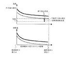
- FIG. 2 is a diagram showing the relationship between the water temperature and the heat radiation amount at each position of the flow path in the heating terminal 8 according to the first embodiment of the present invention.
- the amount of heat radiation at each position of the hot water flow path in the heating terminal 8 also decreases overall.
- the amount of heat radiated from the heating terminal 8 increases or decreases depending on the temperature difference between the water temperature and room temperature. For example, if the temperature difference between the temperature of water and room temperature is small, heat is hardly released. Therefore, there is a temperature difference between the room temperature and the temperature of water, which is a heat dissipation limit for heat exchange. At the outlet of the heating terminal 8, the temperature of the water when almost no heat is released becomes the lower limit of the return hot water temperature. The temperature difference between the water temperature and room temperature at this time is the heat radiation limit temperature difference. This heat radiation limit temperature difference is about 3 to 5° C., although it depends on the performance of the heating terminal 8.
- the heat radiation amount as the heating terminal 8 obtained by summing the heat radiation amount at each position of the hot water flow path in the heating terminal 8 is represented by Expression (2).
- the amount of heat radiation increases when the hot water temperature is higher than the room temperature and decreases when the hot water temperature is low.
- the control device 100 changes the target outgoing hot water temperature, which is the target value of the outgoing hot water temperature, to control the outgoing hot water temperature.
- the target forward hot water temperature is the target forward heat medium temperature.
- Q is the heat radiation amount (kW) from the heating terminal 8.
- K is the heat transfer coefficient (W/m 2 ⁇ K) of the heating terminal 8
- A is the heat transfer area (m 2 ) of the heating terminal 8.
- Tws is the forward hot water temperature (K)
- Tr is the room temperature (K).
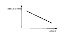
- FIG. 3 is a diagram showing a relationship between the outside air temperature and the target outgoing hot water temperature according to the first embodiment of the present invention.
- the heating load when the outside air temperature is low, the heating load is large, so the forward hot water temperature is raised to increase the amount of heat radiation.
- the heating load when the outside air temperature is high, the heating load is small, so the temperature of the hot water is lowered to reduce the amount of heat radiation.
- the heating load increases, so the forward hot water temperature is raised to increase the amount of heat radiation.
- the heating load is reduced, so the forward hot water temperature is lowered to reduce the amount of heat radiation.
- FIG. 4 is a diagram showing a relationship between the outgoing hot water temperature and the heat radiation amount of the heating terminal 8 according to the first embodiment of the present invention.
- the heat radiation amount of the heating terminal 8 when the forward hot water temperature is changed changes as shown in FIG. It can be seen from FIG. 4 that the temperature of water and the amount of heat radiation have a substantially proportional relationship in a region above a certain temperature. However, when the temperature of the water is too low, the heat radiation limit is reached in the middle of the flow path in the heating terminal 8, so that the heat radiation amount is hardly obtained.
- FIG. 5 is a diagram illustrating a relationship between various temperatures when the heat pump device 1 according to the first embodiment of the present invention is frequently started and stopped.
- the heat pump device 1 When the heat radiation amount is significantly reduced, the heat pump device 1 is repeatedly started and stopped.
- the outgoing hot water temperature changes as shown in FIG.
- the control device 100 performs control so that the outgoing hot water temperature does not greatly deviate from the target outgoing hot water temperature and causes excessive heat supply or insufficient heat supply. Therefore, when a deviation of a predetermined value or more occurs between the outgoing hot water temperature and the target outgoing hot water temperature, the heat pump device 1 is started or stopped.
- the control device 100 determines that the amount of heat supply is excessive when the outgoing hot water temperature is higher than the target outgoing hot water temperature by 2° C., and stops the heat pump device 1. When the heat pump device 1 stops, the amount of heat supplied to the water is not supplied, so that the temperature of the outgoing hot water drops to the temperature of the returning hot water. When the heat is radiated from the pipe due to the passage of time and the hot water temperature further decreases, the control device 100 determines that restart is necessary, starts the heat pump device 1, and restarts heating.
- the heat pump device 1 is repeatedly activated and deactivated. Trigger stop hunting. If such start-up and stop are repeated frequently, the refrigeration cycle of the heat pump device 1 is not stable for a longer period of time, and the average period COP is reduced.
- FIG. 6 is a diagram showing a relationship between the hot water flow rate and the heat radiation amount of the heating terminal 8 according to the first embodiment of the present invention.
- the heat radiation amount of the heating terminal 8 is as shown in FIG. To change.
- the warm water flow rate is gradually reduced, the amount of heat radiation gradually decreases in a region up to a certain hot water flow rate. Then, in a region below a certain hot water flow rate, the heat transfer coefficient from the hot water to the heating terminal 8 is significantly reduced, and the heat radiation amount is significantly reduced.
- the control device 100 can lower the pressure of the refrigerant circuit refrigerant to lower the condensing temperature by lowering the driving frequency of the compressor 2 in the heat pump device 1 when the return hot water temperature lowers. For this reason, generally, the COP of the heat pump device 1 serving as a heating device is improved. Therefore, in the range of the warm water flow rate in which the heat radiation amount of the heating terminal 8 changes gently, the improvement of the COP of the heat pump device 1 exceeds the reduction of the heat radiation amount, so that the COP of the entire system rises as the flow amount decreases. ..
- FIG. 7 is a diagram showing a relationship between the hot water flow rate and the COP of the heat pump device 1 according to the first embodiment of the present invention.
- the COP of the heat pump device 1 due to the decrease in the hot water flow rate changes as shown in FIG. 7. Due to the relationship between the heating terminal 8 and the heat pump device 1 as described above, in the heat pump hot water heating system, in order to perform a high COP operation, the characteristics of the heating terminal 8 are grasped and the COP shown in FIG. 7 increases. Or determine the point of decrease. Then, the hot water flow rate is set so that the COP becomes high.
- the target hot water temperature may be determined by learning the characteristics of the heating terminal 8 and the heat insulation characteristics of the house from the data obtained by driving.
- the characteristics of the heating terminal 8 are regarded as one heating terminal 8 in which the characteristics of the plurality of heating terminals 8 are combined, and the control device 100 performs the learning process based on the data obtained from the operation of the system. I do.
- the characteristics of the heating terminal 8 include a flow rate change characteristic and a temperature change characteristic. Therefore, one of the conditions is fixed and the other is changed, the system is operated, and data is acquired.
- the target forward hot water temperature is kept constant at a temperature at which the return hot water temperature does not reach the heat radiation limit (for example, about 45° C.), and then the rotation speed of the circulation pump 7 is reduced from the rated rotation speed to change the rotation speed.
- the relationship between the flow rate and the hot water flow rate is stored in the storage device 120 as data.
- the coefficient in the region where the heat radiation amount changes proportionally is obtained from the data of the flow rate and the heat radiation amount by the least square method or the like.
- ⁇ and ⁇ are coefficients.
- the ⁇ of the equation (5) is calculated from the data of the heat supply amount of the heat pump device 1 when the target forward hot water temperature is changed while the circulation pump 7 is maintained at the rated speed by the least square method or the like.
- the room temperature is the room temperature of the representative room in which the remote controller 9 having the room temperature sensor 14 is installed, or if a plurality of remote controllers 9 are installed. , Use the average room temperature of each room.
- ⁇ is a heat dissipation coefficient of the heating terminal 8.
- ⁇ of the equation (6) is obtained from the data of the room temperature Tr, the outside air temperature Ta, and the heat supply amount Q of the heat pump device 1.
- ⁇ is a heat dissipation coefficient in an installation environment such as a house.
- the coefficients obtained by the equations (4) to (6) are stored in the storage device 120 in advance as data. Based on the current data of the outside air temperature Ta and the room temperature Tr, the target forward hot water temperature Twset is finally determined by the equation (7).
- Qb is the heat radiation amount (kW) at the rated flow speed at the hot water flow rate, which is obtained based on the equation (4).
- Qc is a heat radiation amount (kW) at the current hot water flow rate, which is obtained from the equation (4).
- control device 100 may determine the target forward hot water temperature by PI control according to the deviation of the room temperature by another method.
- Expression (8) represents an expression relating to the speed type digital PI control.
- ⁇ Twset(i) is the target forward hot water temperature change amount calculated value (K).
- e(i) is the current room temperature deviation (Trset-Tr(i))
- i is the data reference index of the current control cycle
- Trset is the target room temperature (K)
- Tr(i) is the current room temperature. Room temperature (K).
- Kp is a proportional gain of the target outgoing hot water temperature control
- Ki is an integral gain of the target outgoing hot water temperature control
- ⁇ t is a control cycle.
- the control device 100 controls the device of the heat pump device 1 so that the outgoing hot water temperature matches the target outgoing hot water temperature. For example, when the control device 100 determines that the deviation between the target forward hot water temperature and the forward hot water temperature has increased, the control device 100 increases the drive frequency of the compressor 2 and expands the opening degree of the expansion valve 4. As a result, the amount of refrigerant circulating in the refrigerant circuit is increased, the amount of heat taken from the outdoor air is increased, and the amount of heat supplied to water is increased. On the contrary, when the control device 100 determines that the deviation is reduced, the control device 100 reduces the drive frequency of the compressor 2 and reduces the opening degree of the expansion valve 4 to reduce the circulation amount of the refrigerant in the refrigerant circuit.
- the degree of change of the drive frequency is determined based on the equation (9) by PI control from the deviation between the forward hot water temperature Two and the target forward hot water temperature Twset.
- ⁇ f(j) is a frequency change amount calculated value (Hz).
- e(j) is the current outflow hot water temperature deviation (Twset-Tws(j))
- j is the data reference index of the current control cycle
- Twset is the target outflow hot water temperature (K)
- Tws(j) Is the current outgoing hot water temperature (K).
- Kp1 is a proportional gain of frequency control
- Ki1 is an integral gain of frequency control
- ⁇ t1 is a control cycle.
- FIG. 8 is a diagram illustrating control of the hot water flow rate of the control device 100 according to the first embodiment of the present invention.
- FIG. 8 shows changes in the hot water flow rate, the hot water temperature, the driving frequency of the compressor 2, and the heat supply amount when the heating load changes.
- the temperature difference between the return hot water temperature and the room temperature is larger than the heat radiation limit temperature difference.
- the return hot water temperature can be kept low by reducing the hot water flow rate. Therefore, the condensing temperature of the heat pump device 1 can be lowered, and the COP can be improved.
- the control device 100 controls so as to change the amount of heat supplied to the heating terminal 8 in accordance with the change in the heating load. The amount of heat supplied to the heating terminal 8 is changed by changing the outgoing hot water temperature.
- the heat radiation amount of the heating terminal 8 decreases, which causes the start and stop hunting of the heat pump device 1. Therefore, the hot water flow rate is increased for operation.
- the temperature difference between the forward hot water temperature and the return hot water temperature for the same amount of heat radiation is reduced. For this reason, it is possible to avoid an excessive rise in the forward hot water temperature, and it is possible to suppress start and stop hunting.
- the target hot water flow rate is obtained using the heat radiation amount obtained by the equation (6) and the equation (10).
- the rotation speed of the circulation pump 7 is controlled by PI control or the like so that the hot water flow rate becomes the target hot water flow rate.
- Fwset is the target hot water flow rate (m 3 /s).
- ⁇ Tw-a is the heat radiation limit temperature difference (K).
- the hot water flow rate is controlled to be the lower limit flow rate, the outgoing hot water temperature does not reach the target outgoing hot water temperature, or it takes too long to reach the target outgoing hot water temperature. There may be a lack of ability. Therefore, in the operating region (3), when the temperature difference between the return hot water temperature and the room temperature is larger than the heat radiation limit temperature difference and the deviation between the forward hot water temperature and the target forward hot water temperature is larger than the set value for the set period, Avoid lowering room temperature due to lack of capacity. Therefore, the hot water flow rate is increased until the going hot water temperature reaches the target going hot water temperature. That is, the control device 100 controls the rotation speed of the circulation pump 7 by PI control or the like according to the deviation of the outgoing hot water temperature.
- the control device 100 maintains the operation of the heat pump device 1 in a high COP state in each of the normal operation region, the low load region, and the high load region by controlling the hot water flow rate. can do.
- the lower limit flow rate and the heat radiation limit temperature difference are obtained in advance by performing a test operation or the like and stored as data in the storage device 120 of the control device 100.
- FIG. 9 is a diagram illustrating a procedure of a method of determining a lower limit flow rate according to the first embodiment of the present invention. A method of determining the lower limit flow rate performed by the control device 100 will be described based on FIG. 9. Here, the processing in the control device 100 is mainly performed by the processing device 110.
- step S001 the control device 100 reads the set room temperature set by the user from the remote controller 9. Further, in step S002, the control device 100 activates the circulation pump 7 and gradually increases the rotation speed. At this time, if the number of revolutions of the circulation pump 7 is rapidly increased to the rated number of revolutions, it takes time for the temperature of the hot water to rise because the water cooled when the heating is stopped circulates in the hot water passage. Therefore, the control device 100 gradually increases the rotation speed of the circulation pump 7. Then, when it is determined in step S003 that the circulation pump 7 has reached the rated rotation speed, the control device 100 stores the hot water flow rate as data in the storage device 120 in step S004.
- step S005 If the control device 100 determines in step S005 that the set time has elapsed after the circulation pump 7 reaches the rated speed, the control device 100 activates the heat pump device 1 in step S006.
- the set time is several minutes.
- the initial drive frequency of the compressor 2 is gradually increased from the minimum drive frequency, or the control device 100 controls the compressor 2 based on the outside air temperature. Determine the drive frequency.
- the control device 100 calculates the target outgoing hot water temperature and updates the value in step S007.
- the target outgoing hot water temperature is calculated using equation (3) or equation (7). Further, the target forward hot water temperature may be controlled according to the room temperature deviation by the PI control of the equation (8).
- step S008 the control device 100 calculates the deviation of the warm hot water temperature from the target warm hot water temperature and the current warm hot water temperature related to the detection of the warm temperature sensor 11. Then, the drive frequency of the compressor 2 is controlled based on the deviation of the forward hot water temperature.
- the drive frequency of the compressor 2 may be changed based on the PI control of the equation (9) or the like in accordance with the deviation of the forward hot water temperature.
- the relationship between the rotation speed of the circulation pump 7 and the hot water flow rate is generally expressed by the quadratic equation of the equation (12).
- the hot water flow rate when the rotation speed of the circulation pump 7 is changed is stored in the storage device 120, and the control device 100 obtains the coefficient of the equation (12) by using the least square method or the like.
- Fw is a hot water flow rate (L/min).
- a and b are coefficients
- Rp is a circulation pump rotation speed (Hz or rpm).
- the control device 100 does not control the opening degree of the flow rate adjusting valve 15, but each flow rate adjusting valve 15 detects the water temperature or the room temperature of the heating terminal 8 and autonomously controls the opening degree. Good. In that case, the control device 100 obtains the relationship between the hot water flow rate and the circulation pump rotation speed in a state where all the flow rate adjustment valves 15 are opened, and the current relationship between the hot water flow rate and the circulation pump rotation speed is calculated by fully opening the flow rate adjustment valves. When it is different from the time relationship, it may be determined that the relationship between the hot water flow rate and the circulation pump rotation speed has changed, the lower limit flow rate and the heat radiation limit temperature difference may be newly calculated, and stored in the storage device 120.
- a plurality of relationships between the rotation speed of the circulation pump 7 and the hot water flow rate are obtained in advance under the condition that the opening/closing states of the flow rate adjusting valves are different, and the lower limit flow rate and the heat radiation limit temperature difference are calculated in a table format for each relationship.
- the data may be stored in the storage device 120 and used for control.
- the heat pump hot water heating system further includes the flow rate adjusting valve 15 that adjusts the flow rate of water passing through each heating terminal 8.
- the flow rate adjusting valve 15 By closing the flow rate adjusting valve 15 corresponding to the heating terminal 8 that does not perform heating, the relationship between the circulation pump 7 rotation speed and the hot water flow rate changes, and the apparent heat dissipation characteristics of the heating terminal 8 seen from the heat pump device 1 change.
- the control device 100 is configured to newly calculate the lower limit flow rate and the heat radiation limit temperature difference according to the change. Therefore, even if the heat dissipation characteristics of the entire heating terminal 8 change, more appropriate lower limit flow rate and heat dissipation limit temperature difference can be set.
- the heat pump hot water heating system having the refrigerant circuit and using the heat pump device 1 for heating using the heat pump cycle as the heating device has been described.
- the present invention can also be applied to a heating system that uses a heat medium that uses another heating device, such as an electric heater, that can perform heat quantity supply control.
Landscapes
- Engineering & Computer Science (AREA)
- Physics & Mathematics (AREA)
- Thermal Sciences (AREA)
- Chemical & Material Sciences (AREA)
- Combustion & Propulsion (AREA)
- Mechanical Engineering (AREA)
- General Engineering & Computer Science (AREA)
- Fluid Mechanics (AREA)
- Steam Or Hot-Water Central Heating Systems (AREA)
Abstract
本発明の暖房システムは、空調対象空間の空気と熱媒体とを熱交換させる暖房端末、熱媒体に圧力を加える循環ポンプおよび熱媒体を加熱する加熱装置を配管接続して、熱媒体を循環させる熱媒体流路を構成し、加熱装置から暖房端末に流れる熱媒体の温度である往き熱媒体温度を検出する往き温度センサと、暖房端末から加熱装置に流れる熱媒体の温度である戻り熱媒体温度を検出する戻り温度センサと、空調対象空間における温度である室温を検出する室温センサと、加熱装置および循環ポンプを制御する制御装置とを備え、制御装置は、戻り熱媒体温度と室温との温度差および往き熱媒体温度と設定された目標往き熱媒体温度との偏差に基づいて、循環ポンプの回転数を制御するものである。
Description
本発明は、高温の水を循環させて、対象空間の暖房を行う暖房システムに関するものである。特に、効率の改善に関するものである。
従来より、温めた水などを、ラジエータ、床暖房、ファンコイルユニットなどの暖房端末に通過させ、空調対象空間である室内を暖房する温水暖房システムが開示されている。ここでは、暖房端末に通過させる流体を水であるものとして説明する。ヒートポンプ式の温水暖房システムは、水を加熱する加熱装置として、空気、水または地中などの熱源から得た熱を利用するヒートポンプ装置を用いる。ヒートポンプ装置、暖房端末および循環ポンプを配管接続して温水流路を構成し、循環ポンプを駆動して、水を循環させ、暖房端末に熱量を供給する。
このような温水暖房システムにおいては、室内の温度である室温と設定室温との差に応じて、ヒートポンプ装置から暖房端末に流れる水の温度である往き温水温度を制御し、室温の維持に必要な熱量を供給する。往き温水温度は、室温に基づいて決定された目標往き温水温度となるように制御される。たとえば、室温が設定室温より低ければ、往き温水温度を上げて供給熱量を増やし、室温が高ければ、往き温水温度を下げて供給熱量を減らす。
ここで、水を加熱するヒートポンプ装置におけるエネルギー効率(COP:Coefficient Of Performance)は、戻り温水温度が上昇すると、冷凍サイクルにおける凝縮温度が上昇するため、低下する。
ヒートポンプ式暖房システムでは、加熱装置となるヒートポンプ装置におけるCOPの低下を避けるため、往き温水温度と戻り温水温度とにおける両方の目標値を定める。そして、往き温水温度の挙動が安定してから、戻り温水温度が目標戻り温水温度となるように、循環ポンプの回転数を制御する。具体的には、戻り温水温度が目標戻り温水温度より高い場合には、循環ポンプの回転数を減らし、戻り温水温度が目標戻り温水温度より低い場合には、循環ポンプの回転数を増やす(たとえば、特許文献1参照)。ここで、目標戻り温水温度は、たとえば、ユーザがリモートコントローラで設定する、または、34℃~45℃、より好ましくは34℃~36℃に設定するのがよいとしている。
また、各暖房端末に流量制御弁を設け、試運転時に多系統同時運転における適正流量となる流量制御弁の開度を求め、各開度のデータを、開度設定テーブルとして記憶する暖房システムがある(たとえば、特許文献2参照)。そして、開度設定テーブルのデータに基づき、戻り温度が、熱源機の効率が下がらない、適当な低温となるように、暖房端末を通過する水の流量を調整する。
上述の特許文献1におけるヒートポンプ温水暖房機では、戻り温水温度を目標戻り温水温度に制御することによって間接的に温水流量を制御している。ただし、目標戻り温水温度の決定方法は、参考値が目安として示されているのみである。ヒートポンプ暖房システムのCOPを常に高い状態で運転するには、住宅などの設置環境によって異なる暖房端末の放熱特性に合わせて温水流量を決定する必要がある。このため、特許文献1に記載された目標戻り温度の設定方法では、温水流量が、COPを常に高い状態に維持できるとはいえない。
また、特許文献2における暖房装置では、戻り温度が、熱源機の効率が下がらない適当な低温となるように、流量を調整するとしている。しかしながら、適当な低温の限界点とそのときの戻り温度および流量設定値とを試運転から求めるにあたり、暖房端末の放熱限界は考慮されていない。このため、暖房端末を含む暖房システムの設定環境に応じた、COPの高い運転ができない可能性がある。
本発明は、上記のような課題を解決するため、COPの高い運転を行うことができる暖房システムを得ることを目的とするものである。
本発明の暖房システムは、空調対象空間の空気と熱媒体とを熱交換させる暖房端末、熱媒体に圧力を加える循環ポンプおよび熱媒体を加熱する加熱装置を配管接続して、熱媒体を循環させる熱媒体流路を構成し、加熱装置から暖房端末に流れる熱媒体の温度である往き熱媒体温度を検出する往き温度センサと、暖房端末から加熱装置に流れる熱媒体の温度である戻り熱媒体温度を検出する戻り温度センサと、空調対象空間における温度である室温を検出する室温センサと、加熱装置および循環ポンプを制御する制御装置とを備え、制御装置は、戻り熱媒体温度と室温との温度差および往き熱媒体温度と設定された目標往き熱媒体温度との偏差に基づいて、循環ポンプの回転数を制御するものである。
本発明によれば、制御装置が、戻り温水温度と室温との温度差と放熱限界温度差との比較および往き温水温度と目標往き温水温度との偏差に基づいて、循環ポンプを制御し、温水流量を制御するようにした。このため、空調対象によって異なる暖房端末の放熱特性に合わせて、加熱装置を高いCOPにより運転することができる。
実施の形態1.
図1は、本発明の実施の形態1に係る暖房システムの構成例を示す図である。ここでは、ヒートポンプ式温水暖房システムについて説明する。図1に示すように、実施の形態1のヒートポンプ式温水暖房システムは、ヒートポンプ装置1、循環ポンプ7および暖房端末8を備える。
図1は、本発明の実施の形態1に係る暖房システムの構成例を示す図である。ここでは、ヒートポンプ式温水暖房システムについて説明する。図1に示すように、実施の形態1のヒートポンプ式温水暖房システムは、ヒートポンプ装置1、循環ポンプ7および暖房端末8を備える。
実施の形態1におけるヒートポンプ装置1は、温水流路を流れる水を加熱する加熱装置となる。ここでは、熱を搬送する媒体である熱媒体として、水を用いる。また熱媒体流路となる温水流路に、水が循環するものとして説明する。ただし、これに限定するものではない。たとえば、不凍液などを含む液体を熱媒体として循環させるようにしてもよい。ヒートポンプ装置1は、圧縮機2、水-冷媒熱交換器3、膨張弁4、空気-冷媒熱交換器5およびファン6を備える。このうち、圧縮機2、水-冷媒熱交換器3の冷媒側流路、膨張弁4および空気-冷媒熱交換器5を配管接続して、冷媒を循環させる冷媒回路を構成する。圧縮機2は、吸入した冷媒を圧縮して吐出する。特に限定するものではないが、実施の形態1における圧縮機2は、たとえば、インバータ回路などにより、駆動周波数を任意に変化させることができる。圧縮機2の駆動周波数の制御は、後述する制御装置100が行う。水-冷媒熱交換器3は、凝縮器としてはたらき、温水流路を流れる水と冷媒回路を流れる冷媒とを熱交換させて、水に熱を伝え、加熱する。減圧装置となる膨張弁4は、冷媒の流量を調節し、冷媒を減圧して膨張させる。ここで、特に限定するものではないが、実施の形態1の膨張弁4は、制御装置100からの指示に基づいて、開度を変化させることができる電子膨張弁であるものとする。空気-冷媒熱交換器5は、蒸発器としてはたらき、室外の空気と冷媒回路を流れる冷媒とを熱交換させ、空気から採熱して冷媒に伝える。ファン6は、室外の空気を空気-冷媒熱交換器5に送り、空気-冷媒熱交換器5の熱交換を促進する。
ここで、実施の形態1では、屋外の空気から採熱する空気式のヒートポンプ装置1であるものとして説明するが、これに限定するものではない。空気-冷媒熱交換器5の代わりに、水または不凍液などの熱媒体と冷媒とを熱交換させる水-冷媒熱交換器としてもよい。そして、水または不凍液などの熱媒体の流路が、地中、地下水または河川水などと接しており、地中、地下水または河川水などから採熱する構成としてもよい。
また、実施の形態1のヒートポンプ式温水暖房システムは、水-冷媒熱交換器3の温水側流路、循環ポンプ7および暖房端末8を配管接続し、熱媒体である水を循環させる温水流路を構成する。循環ポンプ7は、温水流路内の水に圧力を加え、温水流路を循環させる。ここで、実施の形態1における循環ポンプ7は、たとえば、インバータ回路などにより、駆動周波数を任意に変化させて回転数を調整し、温水流路を流れる水の流量を調節することができる。循環ポンプ7の回転数の制御は、後述する制御装置100が行う。暖房端末8は、温水流路内の水の熱を、空調対象空間である室内の空気に供給する。暖房端末8は、たとえば、ラジエータ、床暖房、ファンコイルユニットなどである。ラジエータは、室内壁面などに設置され、輻射熱によって、水の熱を室内に放熱する。床暖房は、床内または床下に設置され、床面を通して、水の熱を室内に放熱する。ファンコイルユニットは、ファンと熱交換器とを有し、ファンが熱交換器を通過させた空気を室内に供給する。ここで、実施の形態1のヒートポンプ式温水暖房システムは、暖房端末8を複数有し、住宅内の各室内にそれぞれ設置されているものとする。
次に、制御系機器について説明する。実施の形態1のヒートポンプ式温水暖房システムは、リモートコントローラ(以下、リモコンという)9は、入力装置(図示せず)を有し、室内の設定温度である設定室温など、ユーザにより入力された指示および設定などを含む信号を、制御装置100に送る。また、表示装置(図示せず)を有し、制御装置100から送られた信号に基づく表示などを行う。また、室温センサ14は、空調対象空間である室内の温度を検出し、検出に係る信号を送る。ここでは、室温センサ14は、リモコン9に内蔵されているものとする。外気温度センサ10は、屋外の温度(以下、外気温度という)を検出し、検出に係る信号を送る。ここで、外気温度センサ10は、ヒートポンプ装置1に設置されているものとする。往き温度センサ11は、温水流路において、ヒートポンプ装置1から流出する熱媒体となる水の温度である往き温水温度(往き熱媒体温度)を検出し、検出に係る信号を送る。戻り温度センサ12は、温水流路において、暖房端末8を通過した後、ヒートポンプ装置1に戻ってくる熱媒体となる水の温度である戻り温水温度(戻り熱媒体温度)を検出し、検出に係る信号を送る。流量センサ13は、温水流路における熱媒体となる水の流量である温水流量(熱媒体流量)を検出し、検出に係る信号を送る。
ヒートポンプ式温水暖房システムの制御装置100は、各種センサからの信号を受信する。そして、制御装置100は、ヒートポンプ装置1の圧縮機2、膨張弁4およびファン6並びに温水流路の循環ポンプ7を制御する。ここで、実施の形態1の制御装置100は、処理装置110、記憶装置120および計時装置130を有する。処理装置110は、信号に含まれる温度などのデータに基づいて、演算および判定などの処理を行い、機器の制御を行う。また、記憶装置120は、処理装置110が処理を行うために必要となるデータを記憶する装置である。計時装置130は、処理装置110が判定などの処理を行う際に必要な時間および期間などの計時を行う、タイマなどの装置である。
ここで、処理装置110は、たとえば、CPU(Central Processing Unit)などの制御演算処理装置を有するマイクロコンピュータなどで構成されているものとする。また、記憶装置120は、たとえば、データを一時的に記憶できるランダムアクセスメモリ(RAM)などの揮発性記憶装置(図示せず)およびハードディスク、データを長期的に記憶できるフラッシュメモリなどの不揮発性の補助記憶装置(図示せず)を有する。記憶装置120には、処理装置110が行う処理手順をプログラムとしたデータを有する。そして、制御演算処理装置がプログラムのデータに基づいて処理を実行して実現する。ただ、これに限定するものではない。処理を行う装置を、たとえば、専用機器(ハードウェア)として、構成してもよい。また、図1では、制御装置100は、独立して設置されているが、設置箇所について限定するものではない。たとえば、ヒートポンプ装置1が制御装置100を有してもよい。
次に、暖房端末8によって、空調対象空間である住宅の各室内に供給される熱量について説明する。ヒートポンプ装置1の加熱により、ヒートポンプ式温水暖房システムが、暖房負荷に対して供給する供給熱量は、往き温水温度、戻り温水温度および温水流量の関係により、式(1)で表される。式(1)において、Qは、供給熱量(kW)である。また、ρは温水の密度(kg/m3)、Cpは、比熱(kJ/kgK)、Fwは、温水流量(m3/s)、Twsは、往き温水温度(K)およびTwrは、戻り温水温度(K)を表す。
[数1]
Q=ρ・Cp・Fw・(Tws-Twr) …(1)
Q=ρ・Cp・Fw・(Tws-Twr) …(1)
図2は、本発明の実施の形態1に係る暖房端末8内における流路の各位置における水の温度と放熱量との関係を示す図である。ヒートポンプ装置1から供給される水が暖房端末8内に流入すると、暖房端末8内の温水流路において、各位置における水の温度と放熱量とは、暖房端末8における水の流出口に向かうにつれて、図2のように変化する。図2に示すように、暖房端末8に流入する水の温度が高いため、暖房端末8の流入口付近では放熱量は多くなる。そして、温水流出口に向かって水の温度が低下し、それに伴って放熱量も減少する。
暖房端末8において水の流入側の温度となる往き温水温度を下げた場合、暖房端末8内の温水流路の各位置における放熱量も全体的に減少する。暖房端末8からの放熱量は、水の温度と室温との温度差によって増減する。たとえば、水の温度と室温との温度差が小さいとほとんど放熱しなくなる。したがって、室温と水の温度との間には、熱交換可能な放熱限界となる温度差が存在する。暖房端末8の流出口において、ほとんど放熱しなくなっているときの水の温度が、戻り温水温度の下限となる。このときの水の温度と室温との温度差が放熱限界温度差となる。この放熱限界温度差は、暖房端末8の性能にもよるが、およそ3~5℃程度が目安である。
暖房端末8内における温水流路の各位置の放熱量が合計された、暖房端末8としての放熱量は、式(2)で表される。放熱量は、室温に対して、往き温水温度が高いと増加し、低いと減少する。外気温度が変化するまたは設定室温が変更されるなどした場合には、室温維持に必要な熱量が変化する。そこで、暖房端末8における放熱量を変化させるため、制御装置100は、往き温水温度の目標値である目標往き温水温度を変更して、往き温水温度を制御する。目標往き温水温度は、目標往き熱媒体温度となる。ここで、Qは、暖房端末8からの放熱量(kW)である。また、Kは、暖房端末8の熱伝達率(W/m2・K)、Aは、暖房端末8の伝熱面積(m2)である。そして、Twsは、往き温水温度(K)、Trは、室温(K)である。
[数2]
Q=K・A・(Tws-Tr) …(2)
Q=K・A・(Tws-Tr) …(2)
図3は、本発明の実施の形態1に係る外気温度と目標往き温水温度との関係を示す図である。たとえば、図3に示すように、外気温度が低いときは、暖房負荷が大きいので、往き温水温度を上げて放熱量を増やす。一方、外気温度が高いときは、暖房負荷が小さいので、往き温水温度を下げて放熱量を減らす。また、設定室温を上げた場合には、暖房負荷が増えるので、往き温水温度を上げて放熱量を増やす。一方、設定室温を下げた場合には、暖房負荷が減るので、往き温水温度を下げて放熱量を減らす。
図4は、本発明の実施の形態1に係る往き温水温度と暖房端末8の放熱量との関係を示す図である。往き温水温度を変化させたときの暖房端末8の放熱量は、図4のように変化する。図4から、ある温度以上の領域では、水の温度と放熱量とが、ほぼ比例の関係になることがわかる。しかし、水の温度が低すぎると、暖房端末8内の流路の途上で放熱限界に至るため、放熱量がほとんど得られなくなる。
図5は、本発明の実施の形態1に係るヒートポンプ装置1の起動および停止が頻繁に発生するときの各種温度の関係について説明する図である。放熱量が大幅に減少すると、ヒートポンプ装置1は、起動および停止を頻繁に繰り返す。このとき、往き温水温度は、図5に示すように変化する。ヒートポンプ式温水暖房システムにおいて、制御装置100は、往き温水温度が目標往き温水温度から大きく外れ、過剰な熱量供給または熱量供給不足を起こさないように制御する。このため、往き温水温度と目標往き温水温度との間に、所定以上の偏差が生じると、ヒートポンプ装置1を起動または停止させる。
たとえば、制御装置100は、往き温水温度が目標往き温水温度より2℃高くなると、熱量供給が過剰になると判断して、ヒートポンプ装置1を停止させる。ヒートポンプ装置1が停止すると、水への熱量供給が行われなくなるため、往き温水温度は、戻り温水温度まで低下する。時間の経過により、配管から放熱されて、さらに往き温水温度が低下すると、制御装置100は、再起動が必要と判断し、ヒートポンプ装置1を起動して、暖房を再開する。
以上のように、暖房端末8の放熱量が大幅に減少すると、相対的にヒートポンプ装置1の能力が過剰となり、往き温水温度の急上昇を招くため、ヒートポンプ装置1の起動および停止を繰り返す、起動および停止ハンチングを誘発する。このような起動および停止の繰り返しが頻発すると、ヒートポンプ装置1の冷凍サイクルが安定しない時間帯が増えるため、期間平均のCOPが低下する。
図6は、本発明の実施の形態1に係る温水流量と暖房端末8の放熱量との関係を示す図である。戻り温水温度が放熱限界温度まで下がらない、十分な高さの往き温水温度において、循環ポンプ7の回転数を変更して温水流量を変化させた場合、暖房端末8の放熱量は、図6のように変化する。温水流量を徐々に減らしていくと、ある温水流量までの領域では、緩やかに放熱量が減少する。そして、ある温水流量以下の領域では、温水から暖房端末8への熱伝達率が著しく低下し、放熱量が大幅に減少する。
制御装置100は、戻り温水温度が低下すると、ヒートポンプ装置1における圧縮機2の駆動周波数を下げるなどして、冷媒回路冷媒の圧力を下げて凝縮温度を下げることができる。このため、一般的には、加熱装置となるヒートポンプ装置1のCOPは向上する。したがって、暖房端末8の放熱量が緩やかに変化する温水流量の範囲では、放熱量の減少より、ヒートポンプ装置1のCOPの向上が上回るため、システム全体としてのCOPは、流量減少に伴って上昇する。
しかし、温水流量を減らし過ぎて、放熱量が大幅に減少する領域に入ってしまうと、ヒートポンプ装置1から供給された熱がほとんど放熱されずに戻ってくることになる。このため、戻り温水温度が上昇し、ひいては往き温水温度の急上昇を招き、図5のような、起動および停止ハンチングが発生する。
図7は、本発明の実施の形態1に係る温水流量とヒートポンプ装置1のCOPとの関係を示す図である。温水流量の減少によるヒートポンプ装置1のCOPは、図7のように変化する。以上のような暖房端末8とヒートポンプ装置1との関係性により、ヒートポンプ式温水暖房システムにおいて、COPの高い運転を行うには、暖房端末8の特性を把握して、図7に示すCOPが増加または減少するポイントを見極める。そして、高いCOPとなるように温水流量を設定する。
制御装置100は、室温センサ14が計測した室温が設定値となるように、目標往き温水温度を決定する。たとえば、室温を設定値に維持するのに必要な往き温水温度が、外気温度によってどのように変化するか、あらかじめわかっている場合、式(3)のように、外気温度に応じて目標往き温水温度を変化させる式をあらかじめ登録しておく。そして、外気温度センサ10が検出した現在の外気温度に基づいて、目標往き温水温度を決定する。ここで、Twsetは、目標往き温水温度(K)である。また、Taは、外気温度(K)である。aおよびbは係数である。
[数3]
Twset=a・Ta+b …(3)
Twset=a・Ta+b …(3)
また、暖房端末8の特性および住宅の断熱特性を、運転により得られたデータから学習し、目標往き温水温度を決定してもよい。ここで、暖房端末8の特性については、複数の暖房端末8の特性が合成された一つの暖房端末8とみなして、制御装置100は、システムの運転から得られたデータに基づいて、学習処理を行う。暖房端末8の特性は、流量変化の特性と、温度変化の特性とがある。そこで、それぞれ一方の条件を固定し、他方を変化させて、システムの運転を行い、データを取得する。
まず、目標往き温水温度を、戻り温水温度が放熱限界にならない程度の温度(たとえば、45℃程度)で一定とした上で、循環ポンプ7の回転数を定格回転数から下げていき、回転数と温水流量との関係を、データとして、記憶装置120に記憶する。そして、式(4)のように、放熱量が比例的に変化する領域での係数を、流量および放熱量のデータより、最小二乗法などで求める。ここで、γおよびδは、係数である。
[数4]
Q=γ・Fw+δ …(4)
Q=γ・Fw+δ …(4)
次に、循環ポンプ7を定格回転数に維持して目標往き温水温度を変化させた場合の、ヒートポンプ装置1の供給熱量のデータから最小二乗法などで、式(5)のαを求める。ここでは、複数の暖房端末8が合成された特性として表してあるので、室温は、室温センサ14が内蔵されたリモコン9が設置された代表部屋の室温、あるいはリモコン9が複数設置されていれば、各部屋の室温の平均値を用いる。ここで、αは、暖房端末8の放熱係数である。
[数5]
Q=α・(Twset-Tr) …(5)
Q=α・(Twset-Tr) …(5)
また、室温Tr、外気温度Taおよびヒートポンプ装置1の供給熱量Qのデータから、式(6)のβを求める。ここで、βは、住宅などの設置環境における放熱係数である。
[数6]
Q=β・(Tr-Ta) …(6)
Q=β・(Tr-Ta) …(6)
式(4)~式(6)で求めた係数を、記憶装置120にあらかじめデータとして記憶しておく。現在の外気温度Taおよび室温Trのデータをもとに、最終的に式(7)で目標往き温水温度Twsetを決定する。ここで、Qbは、式(4)に基づいて求めた、定格回転数での温水流量における放熱量(kW)である。また、Qcは、式(4)から求めた、現在の温水流量での放熱量(kW)である。
[数7]
Twset=β/(α・Qc/Qb)・(Tr-Ta)+Tr …(7)
Twset=β/(α・Qc/Qb)・(Tr-Ta)+Tr …(7)
さらに、制御装置100は、別の方法で、室温の偏差に応じてPI制御によって目標往き温水温度を決定してもよい。式(8)は、速度式のディジタルPI制御に関する式を表す。ここで、ΔTwset(i)は、目標往き温水温度変化量計算値(K)である。また、e(i)は、現在の室温偏差(Trset-Tr(i))、iは、現在の制御周期のデータ参照インデックス、Trsetは、目標室温(K)、Tr(i)は、現在の室温(K)である。そして、Kpは、目標往き温水温度制御の比例ゲイン、Kiは、目標往き温水温度制御の積分ゲイン、Δtは、制御周期である。
[数8]
ΔTwset(i)=Kp{e(i)-e(i-1)}
+Ki・e(i)・Δt …(8)
ΔTwset(i)=Kp{e(i)-e(i-1)}
+Ki・e(i)・Δt …(8)
制御装置100は、往き温水温度が、目標往き温水温度と一致するように、ヒートポンプ装置1の機器を制御する。たとえば、制御装置100は、目標往き温水温度と往き温水温度との偏差が大きくなったものと判定すると、圧縮機2の駆動周波数を上昇させると共に、膨張弁4の開度を拡張する。これにより、冷媒回路における冷媒の循環量を増やし、屋外の空気からの採熱を増やして、水への熱量供給を多くする。反対に、制御装置100は、偏差が小さくなったものと判定すると、圧縮機2の駆動周波数を低下させると共に、膨張弁4の開度を縮小することによって、冷媒回路における冷媒の循環量を減らし、室外の空気からの採熱を減らして、水への熱量供給を少なくする。駆動周波数の変化度合いは、たとえば、往き温水温度Twoと目標往き温水温度Twsetとの偏差から、PI制御によって、式(9)に基づいて決定する。ここで、Δf(j)は、周波数変化量計算値(Hz)である。また、e(j)は、現在の往き温水温度偏差(Twset-Tws(j))、jは、現在の制御周期のデータ参照インデックス、Twsetは、目標往き温水温度(K)、Tws(j)は、現在の往き温水温度(K)である。そして、Kp1は、周波数制御の比例ゲイン、Ki1は、周波数制御の積分ゲイン、Δt1は、制御周期である。
[数9]
Δf(j)=Kp1{e(j)-e(j-1)}
+Ki1・e(j)・Δt1 …(9)
Δf(j)=Kp1{e(j)-e(j-1)}
+Ki1・e(j)・Δt1 …(9)
図8は、本発明の実施の形態1に係る制御装置100の温水流量の制御について説明する図である。図8は、暖房負荷が変化したときの温水流量、温水温度、圧縮機2の駆動周波数および供給熱量の変化を表している。運転領域(1)では、戻り温水温度と室温との温度差は、放熱限界温度差より大きくなっている。運転領域(1)では、温水流量を少なくすることによって、戻り温水温度を低く保つことができる。このため、ヒートポンプ装置1の凝縮温度を低くすることができ、COPが向上する。したがって、運転領域(1)では、往き温水温度と目標往き温水温度との偏差が許容値の範囲内であり、戻り温水温度と室温との温度差が放熱限界温度差より大きいとして、温水流量が下限流量となるように制御する。ここで、制御装置100は、暖房負荷の変化に合わせて、暖房端末8への供給熱量を変化させるように制御する。暖房端末8への供給熱量は、往き温水温度を変化させることで変化させる。
暖房負荷が減少していき、戻り温水温度と室温の温度差が放熱限界に達する運転領域(2)では、暖房端末8の放熱量が減少することにより、ヒートポンプ装置1の起動および停止ハンチングを誘発するため、温水流量を増加させて運転する。温水流量を増加させることで、同一放熱量当たりの往き温水温度と戻り温水温度との温度差が減少する。このため、往き温水温度の過度の上昇を避けることができ、起動および停止ハンチングを抑制することができる。運転領域(2)では、式(6)によって求めた放熱量と、式(10)とを用いて、目標温水流量を求める。そして、温水流量が目標温水流量となるように循環ポンプ7の回転数をPI制御などにより制御する。ここで、Fwsetは、目標温水流量(m3/s)である。また、ΔTw-aは、放熱限界温度差(K)である。
[数10]
Fwset=Q/[ρCp・{Twset-(Tr+ΔTw-a)}]
…(10)
Fwset=Q/[ρCp・{Twset-(Tr+ΔTw-a)}]
…(10)
一方、高負荷運転領域となる運転領域(3)では、温水流量が下限流量となるように制御すると、往き温水温度が目標往き温水温度に到達しないか、到達しても時間がかかり過ぎるなど、能力不足となる場合がある。そこで、運転領域(3)において、戻り温水温度と室温との温度差が放熱限界温度差より大きく、往き温水温度と目標往き温水温度との偏差が設定値より大きい状態が設定期間継続したとき、能力不足によって室温が低下することを避けるようにする。このため、往き温水温度が目標往き温水温度になるまで温水流量を増加させる。すなわち、制御装置100が、往き温水温度の偏差に応じて、循環ポンプ7の回転数を、PI制御などにより制御する。
以上のようにして、制御装置100は、温水流量を制御することによって、通常の運転領域、低負荷領域および高負荷領域の各運転領域で、ヒートポンプ装置1の運転を、COPの高い状態で維持することができる。この方法では、試運転などを行って、下限流量および放熱限界温度差をあらかじめ求めておき、制御装置100の記憶装置120にデータとして記憶させておくようにする。
図9は、本発明の実施の形態1に係る下限流量の決定方法の手順について説明する図である。図9に基づいて、制御装置100が行う下限流量を決定する方法について説明する。ここで、制御装置100における処理は、主として、処理装置110が行う。
[下限流量決定方法]
ヒートポンプ式温水暖房システムを起動すると、まず、ステップS001において、制御装置100は、ユーザがリモコン9から設定した設定室温を読み込む。また、ステップS002において、制御装置100は、循環ポンプ7を起動させ、回転数を段階的に上げていく。このとき、循環ポンプ7の回転数を、急激に定格回転数まで上げると、暖房停止時に冷えていた水が温水流路を循環することで、温水が温度上昇するのに時間がかかる。そこで、制御装置100は、循環ポンプ7の回転数を段階的に上げる。そして、制御装置100は、ステップS003において、循環ポンプ7が定格回転数まで達したものと判定すると、ステップS004において、温水流量をデータとして記憶装置120に記憶する。
ヒートポンプ式温水暖房システムを起動すると、まず、ステップS001において、制御装置100は、ユーザがリモコン9から設定した設定室温を読み込む。また、ステップS002において、制御装置100は、循環ポンプ7を起動させ、回転数を段階的に上げていく。このとき、循環ポンプ7の回転数を、急激に定格回転数まで上げると、暖房停止時に冷えていた水が温水流路を循環することで、温水が温度上昇するのに時間がかかる。そこで、制御装置100は、循環ポンプ7の回転数を段階的に上げる。そして、制御装置100は、ステップS003において、循環ポンプ7が定格回転数まで達したものと判定すると、ステップS004において、温水流量をデータとして記憶装置120に記憶する。
また、制御装置100は、ステップS005において、循環ポンプ7が定格回転数に達してから、設定時間が経過したものと判定すると、ステップS006において、ヒートポンプ装置1を起動させる。ここで、設定時間は、数分間とする。また、ヒートポンプ装置1を起動させる際、圧縮機2の初期の駆動周波数については、最小の駆動周波数から徐々に上げていくか、または、制御装置100が、外気温度に基づいて、圧縮機2の駆動周波数を決定する。
制御装置100は、ステップS007において、目標往き温水温度を計算し、値を更新する。目標往き温水温度は、式(3)あるいは式(7)を用いて計算する。また、式(8)のPI制御で室温偏差に応じて目標往き温水温度を制御するものでもよい。
制御装置100は、ステップS008において、目標往き温水温度と往き温度センサ11の検出に係る現在の往き温水温度とから往き温水温度偏差を計算する。そして、往き温水温度偏差に基づいて、圧縮機2の駆動周波数を制御する。ここで、往き温水温度偏差に応じて、式(9)のPI制御などに基づいて、圧縮機2の駆動周波数を変更するようにしてもよい。
制御装置100は、ステップS009において、システムの動作が安定しているかどうかを判定する。制御装置100は、動作が安定しているかを判定するために、室温が設定室温の値に到達し、所定期間における往き温水温度の平均偏差が、あらかじめ定めた設定範囲内にあるかどうかを確認する。制御装置100は、室温が設定室温に到達していない、または、往き温水温度の偏差が大きいと判定すると、動作が安定していないと判定し、ステップS007に戻る。制御装置100は、動作が安定していると判定すると、ステップS010に移る。
制御装置100は、ステップS010において、所定期間の温水流量および平均放熱量の値をデータとして記憶する。供給熱量を表す放熱量については、前述した式(1)を用いて計算する。また、流量変化回数が、2回目以降の場合には、前回と今回との温水流量の差分および前回と今回との放熱量の差分から、式(11)に基づいて、流量変化に対する放熱量変化率であるΔQ/ΔFwを計算する。ここで、ΔQは、放熱量の変化量(kW)、ΔFw:流量の変化量(L/min)である。また、kは、現在のサンプル値のインデックスである。
[数11]
ΔQ(k)/ΔFw(k)=
{Q(k)-Q(k-1)}/{Fw(k)-Fw(k-1)}
…(11)
ΔQ(k)/ΔFw(k)=
{Q(k)-Q(k-1)}/{Fw(k)-Fw(k-1)}
…(11)
そして、制御装置100は、ステップS011において、放熱量変化率が、あらかじめ設定された設定値以上であるかどうかを判定する。ここで、設定値は、たとえば、10%とする。放熱量変化率が、設定値より低いと判定すると、ステップS012において、循環ポンプ7の回転数を、あらかじめ定められた設定回転割合だけ減少させて、ステップS007に戻る。ここで、設定回転割合は、たとえば、10%とする。
また、ステップS011において、放熱量変化率が設定値以上であると判定すると、流量が少な過ぎて暖房端末8の熱伝達率が大きく減少したものとする。そして、ステップS013において、前回の流量Fw(k-1)を下限流量として設定し、データとして記憶して、処理を終了する。
図10は、本発明の実施の形態1に係る放熱限界温度差決定方法の手順について説明する図である。図10に基づいて、制御装置100が行う戻り温水温度と室温との放熱限界温度差決定方法について説明する。ここで、制御装置100における処理は、主として、処理装置110が行う。
[戻り温水温度と室温との放熱限界温度差決定方法]
制御装置100は、ステップS101において、目標往き温水温度を設定する。ここで、目標往き温水温度は、たとえば、45℃など、暖房端末8からの放熱が十分に行える程度の温度に設定する。制御装置100は、図9で説明した処理と同様に、ステップS102において、循環ポンプ7を起動させ、回転数を段階的に上げていく。そして、制御装置100は、ステップS103において、循環ポンプ7が定格回転数まで達したと判断し、さらに、ステップS104において、設定時間が経過したものと判定すると、ステップS105において、ヒートポンプ装置1を起動させる。
制御装置100は、ステップS101において、目標往き温水温度を設定する。ここで、目標往き温水温度は、たとえば、45℃など、暖房端末8からの放熱が十分に行える程度の温度に設定する。制御装置100は、図9で説明した処理と同様に、ステップS102において、循環ポンプ7を起動させ、回転数を段階的に上げていく。そして、制御装置100は、ステップS103において、循環ポンプ7が定格回転数まで達したと判断し、さらに、ステップS104において、設定時間が経過したものと判定すると、ステップS105において、ヒートポンプ装置1を起動させる。
制御装置100は、ステップS106において、目標往き温水温度を更新する。ここで、2回目以降の更新については、目標往き温水温度が、元の温度よりも低い温度に段階的に下げる更新を行う。目標往き温水温度の下げ幅は、たとえば、1℃とする。そして、ステップS107において、往き温水温度偏差に応じて圧縮機2の駆動周波数を制御する。
制御装置100は、ステップS108において、たとえば、所定期間におけるヒートポンプ装置1の起動回数を計数し、起動回数が閾値以上か否かを判定する。ここで、所定期間は1時間とし、起動回数の閾値は、3~5回程度とする。制御装置100は、所定時間における起動回数が閾値より少ないと判定すると、ステップS106に戻る。起動回数が閾値より少なければ、室温と戻り温水温度との温度差が放熱限界に達していないと判断する。このため、戻り温水温度を下げることは可能である。制御装置100が、ステップS103~ステップS105の処理を繰り返すと、往き温水温度および戻り温水温度は下がっていく。
そして、戻り温水温度と室温との温度差が放熱限界温度差まで達すると、放熱量が減少し、ヒートポンプ装置1の停止および起動の動作が発生し、起動回数が増加する。制御装置100は、ステップS108において、起動回数が閾値を超えたと判定すると、放熱限界温度差に達したとする。そして、制御装置100は、ステップS109において、平均戻り熱媒体温度となる平均戻り温水温度に対し、平均戻り温水温度-平均室温+αを、放熱限界温度差として記憶装置120に記憶する。ここで、αは、マージンである。
ここでは、ヒートポンプ装置1の起動回数が閾値より大きいか否かを、放熱限界温度差の判定条件としたが、これに限定するものではない。所定期間におけるヒートポンプ装置1の運転中の平均往き温水温度が、目標往き温水温度より、ある温度以上に高くなったかどうかを、放熱限界温度差の判定条件としてもよい。この現象も、暖房端末8の放熱量が大幅に減少していることを意味する。
以上のように、実施の形態1のヒートポンプ式温水暖房システムによれば、暖房端末8における暖房負荷が低負荷のときには、暖房端末8の放熱限界となる温度以上に、戻り温水温度を維持するようにしたので、ヒートポンプ装置1の効率低下を招く、ヒートポンプ装置1の停止および起動の頻発を防ぐことができる。また、暖房負荷が高負荷のときには、温水流量を増やすことで暖房端末8の放熱量を増やして供給する熱量の不足を避ける。それ以外の負荷における運転領域のときには、ヒートポンプ装置1を効率が高い下限流量で運転することができる。したがって、異なる負荷条件においてもヒートポンプ装置1の効率を高く維持することができる。
また、実施の形態1のヒートポンプ式温水暖房システムによれば、制御装置100は、対象空間毎に異なる暖房端末8の放熱効率が大きく低下する、温水流量の変曲点に係るデータを記憶装置120に記憶することができる。このため、加熱装置であるヒートポンプ装置1を高い効率で運転することができる、下限温水流量を適切に設定することができる。
さらに、実施の形態1のヒートポンプ式温水暖房システムによれば、本請求項により、住宅毎に異なる暖房端末8の放熱限界となる温度差を演算処理して、データとして記憶装置120に記憶しておくことで、戻り温水温度を下限温度以上に保つことができる。このため、加熱装置であるヒートポンプ装置1を高い効率で運転することができる。
実施の形態2.
図11は、本発明の実施の形態2に係る暖房システムの構成例を示す図である。実施の形態2のヒートポンプ式温水暖房システムは、電力計測装置200をさらに備える。電力計測装置200は、ヒートポンプ装置1および循環ポンプ7の消費電力を計測する。制御装置100の処理装置110は、暖房端末8の放熱量を、ヒートポンプ装置1と循環ポンプ7との合計電力で割った値を計算して、ヒートポンプ式温水暖房システム全体における所定期間の平均COPを求める。そして、COPの変化傾向から下限流量を求める。
図11は、本発明の実施の形態2に係る暖房システムの構成例を示す図である。実施の形態2のヒートポンプ式温水暖房システムは、電力計測装置200をさらに備える。電力計測装置200は、ヒートポンプ装置1および循環ポンプ7の消費電力を計測する。制御装置100の処理装置110は、暖房端末8の放熱量を、ヒートポンプ装置1と循環ポンプ7との合計電力で割った値を計算して、ヒートポンプ式温水暖房システム全体における所定期間の平均COPを求める。そして、COPの変化傾向から下限流量を求める。
図12は、本発明の実施の形態2に係る下限流量の決定方法の手順について説明する図である。図12において、図9と同じステップ番号を付している処理については、実施の形態1で説明したことと同様の処理を行う。
実施の形態1で説明した下限流量決定方法では、制御装置100は、図9に示すように、放熱量変化率を求めた。実施の形態2では、制御装置100は、放熱量変化率を求める代わりに、ステップS010Aにおいて、COPを求める。そして、ステップS011Aにおいて、制御装置100は、今回のCOPが前回のCOPより低くなったかどうかを判定し、前回のCOPと今回のCOPとを比較する。図7に示すように、温水流量を減らしていったときのCOPの変化が上昇から下降に転じ、今回のCOPが前回のCOPより低くなったと判定すると、前回の温水流量の値を下限流量として決定する。
以上のように、実施の形態2のヒートポンプ式温水暖房システムにおいては、温水流量が減少したときの効率変化を、より直接的に評価できる。このため、加熱装置となるヒートポンプ装置1を高い効率で運転することができる下限流量を適切に設定することができる。ここで、COPを求めるにあたり、ここでは、電力計測装置200によって、直接、電力計測したが、これに限定するものではない。圧縮機2の駆動周波数と消費電力との関係を表す関係式または関係を表すテーブル形式のデータに基づいて、圧縮機2の駆動周波数から間接的に消費電力を求めてもよい。
実施の形態3.
図13は、本発明の実施の形態3に係る暖房システムの構成例を示す図である。実施の形態3のヒートポンプ式温水暖房システムは、各暖房端末8に対応して流量調整弁15をさらに備えたものである。
図13は、本発明の実施の形態3に係る暖房システムの構成例を示す図である。実施の形態3のヒートポンプ式温水暖房システムは、各暖房端末8に対応して流量調整弁15をさらに備えたものである。
流量調整弁15は、暖房端末8の流入口または流出口に設置され、開度を開閉または段階的に調整することによって暖房端末8を通過する水の流量を調整する。ここでは、制御装置100が流量調整弁15の開度制御を行う。制御装置100は、室温が設定室温に到達したと判定すると、流量調整弁15の弁の開度を縮小して温水流量を減少させる、または弁を閉じ、暖房端末8に水が通過しないようにする。
たとえば、暖房端末8としてラジエータが用いられる場合は、TRV(Thermostatic Radiator Valve)と呼ばれる調整弁を有する。TRVの室温または温水温度設定によって、所望温度に到達した場合には、TRVが閉じる。TRVが閉じられると、温水流路全体の圧力損失が変化する。このため、循環ポンプ7の回転数と温水流路との関係が変化する。このとき、ヒートポンプ装置1から見た、複数の暖房端末8が合成された見かけの放熱特性が変化する。
ここで、すべての暖房端末8を使用しているときの下限流量および放熱限界温度差が、一部の暖房端末8が停止した条件においても最適な条件であるとは限らない。そこで、制御装置100は、循環ポンプ7の回転数と温水流量との関係を示す複数のデータを、記憶装置120に記憶する。そして、制御装置100は、この関係が変化したと判定すると、変化後における下限流量と放熱限界温度差とをあらためて計算して、記憶装置120に記憶する。
循環ポンプ7の回転数と温水流量との関係は、一般に、式(12)の二次式で表される。循環ポンプ7の回転数を変化させたときの温水流量を、記憶装置120に記憶し、制御装置100は、最小二乗法などを用いて、式(12)の係数を求める。ここで、Fwは、温水流量(L/min)である。また、aおよびbは係数、Rpは、循環ポンプ回転数(Hzまたはrpm)である。
[数12]
Fw=a・Rp2+b …(12)
Fw=a・Rp2+b …(12)
なお、制御装置100が流量調整弁15の開度を制御するものでなく、個々の流量調整弁15が暖房端末8の水温や室温を検知して自律的に開度を制御するものであってもよい。その場合、制御装置100は、すべての流量調整弁15が開いた状態の温水流量と循環ポンプ回転数の関係を求めておき、現在の温水流量と循環ポンプ回転数の関係が、流量調整弁全開時の関係と異なる場合に、温水流量と循環ポンプ回転数の関係が変化したと判定し、下限流量と放熱限界温度差とをあらためて計算し、記憶装置120に記憶するものでもよい。また、循環ポンプ7の回転数と温水流量との関係を、各流量調整弁の開閉状況が異なる条件であらかじめ複数求めておき、それぞれの関係について、下限流量と放熱限界温度差とを、テーブル形式のデータなどで記憶装置120に記憶させておき、制御の際に用いてもよい。
以上のように、実施の形態3のヒートポンプ式温水暖房システムにおいては、各暖房端末8を通過する水の流量を調整する流量調整弁15をさらに備えた。暖房を行わない暖房端末8に対応する流量調整弁15を閉じることで、循環ポンプ7回転数と温水流量の関係が変化し、ヒートポンプ装置1から見た、みかけの暖房端末8の放熱特性が変化する。このとき、制御装置100は、変化に応じて、あらためて下限流量および放熱限界温度差を算出するなどするようにした。このため、暖房端末8全体の放熱特性が変化しても、より適切な下限流量および放熱限界温度差を設定することができる。
前述した実施の形態1~実施の形態3においては、冷媒回路を有し、ヒートポンプサイクルを用いた加熱を行うヒートポンプ装置1を加熱装置とするヒートポンプ式温水暖房システムについて説明した。たとえば、熱量供給制御を行うことができる、電気ヒータなど、他の加熱装置を用いる熱媒体を利用する暖房システムについても適用することができる。
1 ヒートポンプ装置、2 圧縮機、3 水-冷媒熱交換器、4 膨張弁、5 空気-冷媒熱交換器、6 ファン、7 循環ポンプ、8 暖房端末、9 リモコン、10 外気温度センサ、11 往き温度センサ、12 戻り温度センサ、13 流量センサ、14 室温センサ、15 流量調整弁、100 制御装置、110 処理装置、120 記憶装置、130 計時装置、200 電力計測装置。
Claims (7)
- 空調対象空間の空気と熱媒体とを熱交換させる暖房端末、前記熱媒体に圧力を加える循環ポンプおよび前記熱媒体を加熱する加熱装置を配管接続して、前記熱媒体を循環させる熱媒体流路を構成し、
前記加熱装置から前記暖房端末に流れる前記熱媒体の温度である往き熱媒体温度を検出する往き温度センサと、
前記暖房端末から前記加熱装置に流れる前記熱媒体の温度である戻り熱媒体温度を検出する戻り温度センサと、
前記空調対象空間における温度である室温を検出する室温センサと、
前記加熱装置および前記循環ポンプを制御する制御装置とを備え、
前記制御装置は、前記戻り熱媒体温度と前記室温との温度差および前記往き熱媒体温度と設定された目標往き熱媒体温度との偏差に基づいて、前記循環ポンプの回転数を制御する暖房システム。 - 前記制御装置は、
前記戻り熱媒体温度と前記室温との温度差が、前記暖房端末において熱交換可能な放熱限界温度差まで減少したものと判定すると、前記熱媒体流路を流れる前記熱媒体の流量である熱媒体流量を増加させるように前記循環ポンプを制御し、
前記戻り熱媒体温度と前記室温との温度差が、前記放熱限界温度差より大きく、前記往き熱媒体温度と前記目標往き熱媒体温度との偏差が設定値より大きい状態があらかじめ定めた設定期間継続したと判定すると、前記往き熱媒体温度が前記目標往き熱媒体温度に到達するまで前記熱媒体流量を増加させるように前記循環ポンプを制御し、
前記往き熱媒体温度と前記目標往き熱媒体温度との偏差が設定範囲内であり、前記戻り熱媒体温度と前記室温との温度差が前記放熱限界温度差より大きいと判定すると、前記熱媒体流量を下限流量に制御するように前記循環ポンプを制御する請求項1に記載の暖房システム。 - 前記制御装置は、前記往き熱媒体温度を一定にして、前記循環ポンプの回転数を定格回転数から下げていき、前記熱媒体流量の変化量に対する供給熱量の変化量の割合を示す放熱量変化率が、あらかじめ設定された設定値になったものと判定すると、前記設定値となったときの前記熱媒体流量を、前記下限流量として設定する請求項2に記載の暖房システム。
- 前記加熱装置および前記循環ポンプの消費電力を計測する電力計測装置を備え、
前記制御装置は、前記往き熱媒体温度を一定にして、前記循環ポンプの回転数を定格回転数から下げていって前記熱媒体流量を減少させていき、前記熱媒体流量に対する供給熱量と前記消費電力との関係から求めたCOPが、増加から減少に変化する変曲点における前記熱媒体流量、前記下限流量として設定する請求項2に記載の暖房システム。 - 前記制御装置は、前記熱媒体流量を一定にして、前記往き熱媒体温度を下げていき、あらかじめ設定された期間における前記加熱装置の起動回数を計数し、前記起動回数が所定の値となった場合に、前記あらかじめ設定された期間における平均戻り熱媒体温度と前記室温との温度差に基づいて、前記放熱限界温度差を設定する請求項2~請求項4のいずれか一項に記載の暖房システム。
- 前記制御装置は、複数の前記下限流量および前記放熱限界温度差のデータを記憶する記憶装置を有し、
前記循環ポンプの回転数と前記熱媒体流量との関係が変化したものと判定すると、変化後における運転による前記下限流量と前記放熱限界温度差とを、前記記憶装置に記憶する請求項2~請求項4のいずれか一項に記載の暖房システム。 - 前記加熱装置は、吸入した冷媒を圧縮する圧縮機と、熱交換により前記冷媒を凝縮させる凝縮器と、凝縮された前記冷媒を減圧させる減圧装置と、減圧された前記冷媒を熱交換により蒸発させる蒸発器とを配管接続して前記冷媒を循環させる冷媒回路を有するヒートポンプ装置である請求項1~請求項6のいずれか一項に記載の暖房システム。
Priority Applications (2)
| Application Number | Priority Date | Filing Date | Title |
|---|---|---|---|
| PCT/JP2018/048154 WO2020136806A1 (ja) | 2018-12-27 | 2018-12-27 | 暖房システム |
| EP18944376.5A EP3904773A4 (en) | 2018-12-27 | 2018-12-27 | HEATING SYSTEM |
Applications Claiming Priority (1)
| Application Number | Priority Date | Filing Date | Title |
|---|---|---|---|
| PCT/JP2018/048154 WO2020136806A1 (ja) | 2018-12-27 | 2018-12-27 | 暖房システム |
Publications (1)
| Publication Number | Publication Date |
|---|---|
| WO2020136806A1 true WO2020136806A1 (ja) | 2020-07-02 |
Family
ID=71129376
Family Applications (1)
| Application Number | Title | Priority Date | Filing Date |
|---|---|---|---|
| PCT/JP2018/048154 Ceased WO2020136806A1 (ja) | 2018-12-27 | 2018-12-27 | 暖房システム |
Country Status (2)
| Country | Link |
|---|---|
| EP (1) | EP3904773A4 (ja) |
| WO (1) | WO2020136806A1 (ja) |
Cited By (3)
| Publication number | Priority date | Publication date | Assignee | Title |
|---|---|---|---|---|
| CN114060903A (zh) * | 2021-12-06 | 2022-02-18 | 河北工业大学 | 一种末端可调供热系统热用户行为节能特征的辨识方法 |
| CN114183810A (zh) * | 2021-12-14 | 2022-03-15 | 浙江广涛卫厨有限公司 | 一种多能源智能联用、分配的控制系统 |
| CN114427698A (zh) * | 2022-03-10 | 2022-05-03 | 浙江广涛卫厨有限公司 | 一种多能源智能联用、分配的控制系统 |
Citations (7)
| Publication number | Priority date | Publication date | Assignee | Title |
|---|---|---|---|---|
| JPS5736504U (ja) * | 1980-08-08 | 1982-02-26 | ||
| JP2001241677A (ja) * | 2000-03-02 | 2001-09-07 | Corona Corp | 温水暖房装置 |
| JP2006284141A (ja) | 2005-04-04 | 2006-10-19 | Tokyo Gas Co Ltd | 暖房装置及び冷房装置 |
| JP2012163275A (ja) | 2011-02-08 | 2012-08-30 | Panasonic Corp | ヒートポンプ温水暖房機 |
| JP2012180965A (ja) * | 2011-03-01 | 2012-09-20 | Daikin Industries Ltd | 暖房装置 |
| JP2017009189A (ja) * | 2015-06-22 | 2017-01-12 | 三菱電機株式会社 | 熱媒体システム |
| WO2017081764A1 (ja) * | 2015-11-11 | 2017-05-18 | 三菱電機株式会社 | 熱媒体循環システム |
Family Cites Families (3)
| Publication number | Priority date | Publication date | Assignee | Title |
|---|---|---|---|---|
| WO2011129248A1 (ja) * | 2010-04-15 | 2011-10-20 | 三菱電機株式会社 | 給湯システム制御装置及び給湯システム制御プログラム及び給湯システム運転方法 |
| EP2615384B1 (en) * | 2010-09-10 | 2019-06-12 | Panasonic Intellectual Property Management Co., Ltd. | Heat medium circulation type heat pump heater |
| EP3364116B1 (en) * | 2017-02-16 | 2020-06-03 | Mitsubishi Electric R&D Centre Europe B.V. | Method for controlling a heat pump system and heat pump system |
-
2018
- 2018-12-27 WO PCT/JP2018/048154 patent/WO2020136806A1/ja not_active Ceased
- 2018-12-27 EP EP18944376.5A patent/EP3904773A4/en active Pending
Patent Citations (7)
| Publication number | Priority date | Publication date | Assignee | Title |
|---|---|---|---|---|
| JPS5736504U (ja) * | 1980-08-08 | 1982-02-26 | ||
| JP2001241677A (ja) * | 2000-03-02 | 2001-09-07 | Corona Corp | 温水暖房装置 |
| JP2006284141A (ja) | 2005-04-04 | 2006-10-19 | Tokyo Gas Co Ltd | 暖房装置及び冷房装置 |
| JP2012163275A (ja) | 2011-02-08 | 2012-08-30 | Panasonic Corp | ヒートポンプ温水暖房機 |
| JP2012180965A (ja) * | 2011-03-01 | 2012-09-20 | Daikin Industries Ltd | 暖房装置 |
| JP2017009189A (ja) * | 2015-06-22 | 2017-01-12 | 三菱電機株式会社 | 熱媒体システム |
| WO2017081764A1 (ja) * | 2015-11-11 | 2017-05-18 | 三菱電機株式会社 | 熱媒体循環システム |
Non-Patent Citations (1)
| Title |
|---|
| See also references of EP3904773A4 |
Cited By (3)
| Publication number | Priority date | Publication date | Assignee | Title |
|---|---|---|---|---|
| CN114060903A (zh) * | 2021-12-06 | 2022-02-18 | 河北工业大学 | 一种末端可调供热系统热用户行为节能特征的辨识方法 |
| CN114183810A (zh) * | 2021-12-14 | 2022-03-15 | 浙江广涛卫厨有限公司 | 一种多能源智能联用、分配的控制系统 |
| CN114427698A (zh) * | 2022-03-10 | 2022-05-03 | 浙江广涛卫厨有限公司 | 一种多能源智能联用、分配的控制系统 |
Also Published As
| Publication number | Publication date |
|---|---|
| EP3904773A1 (en) | 2021-11-03 |
| EP3904773A4 (en) | 2021-12-15 |
Similar Documents
| Publication | Publication Date | Title |
|---|---|---|
| JP5657110B2 (ja) | 温度調節システム及び空気調和システム | |
| JP5452581B2 (ja) | ヒートポンプシステム及びヒートポンプ装置の制御方法 | |
| JP5524571B2 (ja) | ヒートポンプ装置 | |
| JP6890706B1 (ja) | 空気調和システムおよび制御方法 | |
| CN102734983B (zh) | 热泵系统以及热泵系统的控制方法 | |
| CN110476492B (zh) | 用于冷却热泵回路中的变换器、尤其是变频器的方法 | |
| JP5476604B2 (ja) | ヒートポンプ温水暖房機 | |
| TWI801460B (zh) | 暖通空調(hvac)系統、用於蒸氣壓縮系統之控制方法以及相關機器可讀媒體 | |
| WO2020136806A1 (ja) | 暖房システム | |
| JP5737173B2 (ja) | 温度および湿度の調整を行う空調システム | |
| JP5673524B2 (ja) | 温度および湿度の調整を行う空調システム | |
| JP6103144B2 (ja) | ヒートポンプ暖房システム | |
| WO2015198424A1 (ja) | ヒートポンプ装置 | |
| JP6537641B2 (ja) | 温冷水空調システム | |
| JP2018169130A (ja) | 空調システム | |
| WO2018087810A1 (ja) | 暖房制御システムおよびヒートポンプ給湯暖房システム | |
| JP2014005961A (ja) | 冷凍サイクル装置及びそれを備えた温水生成装置 | |
| JP5818601B2 (ja) | ヒートポンプ式熱源機 | |
| JP6094518B2 (ja) | ヒートポンプ式暖房給湯装置 | |
| JP5768151B2 (ja) | ヒートポンプ式空調機およびヒートポンプ式空調機の制御方法 | |
| WO2022176273A1 (ja) | ヒートポンプ式熱源装置 | |
| JP6979361B2 (ja) | 浴室暖房機 | |
| JP5772665B2 (ja) | ヒートポンプ式給湯装置 | |
| WO2020240685A1 (ja) | 制御装置、空気環境調整システム、空気環境調整方法、プログラム、及び記録媒体 | |
| JP7011948B2 (ja) | 暖房システム |
Legal Events
| Date | Code | Title | Description |
|---|---|---|---|
| 121 | Ep: the epo has been informed by wipo that ep was designated in this application |
Ref document number: 18944376 Country of ref document: EP Kind code of ref document: A1 |
|
| NENP | Non-entry into the national phase |
Ref country code: DE |
|
| ENP | Entry into the national phase |
Ref document number: 2018944376 Country of ref document: EP Effective date: 20210727 |
|
| NENP | Non-entry into the national phase |
Ref country code: JP |