WO2020136956A1 - ハロゲン化物の製造方法 - Google Patents
ハロゲン化物の製造方法 Download PDFInfo
- Publication number
- WO2020136956A1 WO2020136956A1 PCT/JP2019/025440 JP2019025440W WO2020136956A1 WO 2020136956 A1 WO2020136956 A1 WO 2020136956A1 JP 2019025440 W JP2019025440 W JP 2019025440W WO 2020136956 A1 WO2020136956 A1 WO 2020136956A1
- Authority
- WO
- WIPO (PCT)
- Prior art keywords
- halide
- firing
- manufacturing
- ionic conductivity
- solid electrolyte
- Prior art date
- Legal status (The legal status is an assumption and is not a legal conclusion. Google has not performed a legal analysis and makes no representation as to the accuracy of the status listed.)
- Ceased
Links
Images


Classifications
-
- C—CHEMISTRY; METALLURGY
- C01—INORGANIC CHEMISTRY
- C01F—COMPOUNDS OF THE METALS BERYLLIUM, MAGNESIUM, ALUMINIUM, CALCIUM, STRONTIUM, BARIUM, RADIUM, THORIUM, OR OF THE RARE-EARTH METALS
- C01F17/00—Compounds of rare earth metals
- C01F17/30—Compounds containing rare earth metals and at least one element other than a rare earth metal, oxygen or hydrogen, e.g. La4S3Br6
- C01F17/36—Compounds containing rare earth metals and at least one element other than a rare earth metal, oxygen or hydrogen, e.g. La4S3Br6 halogen being the only anion, e.g. NaYF4
-
- H—ELECTRICITY
- H01—ELECTRIC ELEMENTS
- H01M—PROCESSES OR MEANS, e.g. BATTERIES, FOR THE DIRECT CONVERSION OF CHEMICAL ENERGY INTO ELECTRICAL ENERGY
- H01M10/00—Secondary cells; Manufacture thereof
- H01M10/05—Accumulators with non-aqueous electrolyte
- H01M10/056—Accumulators with non-aqueous electrolyte characterised by the materials used as electrolytes, e.g. mixed inorganic/organic electrolytes
- H01M10/0561—Accumulators with non-aqueous electrolyte characterised by the materials used as electrolytes, e.g. mixed inorganic/organic electrolytes the electrolyte being constituted of inorganic materials only
- H01M10/0562—Solid materials
-
- C—CHEMISTRY; METALLURGY
- C01—INORGANIC CHEMISTRY
- C01P—INDEXING SCHEME RELATING TO STRUCTURAL AND PHYSICAL ASPECTS OF SOLID INORGANIC COMPOUNDS
- C01P2006/00—Physical properties of inorganic compounds
- C01P2006/40—Electric properties
-
- H—ELECTRICITY
- H01—ELECTRIC ELEMENTS
- H01B—CABLES; CONDUCTORS; INSULATORS; SELECTION OF MATERIALS FOR THEIR CONDUCTIVE, INSULATING OR DIELECTRIC PROPERTIES
- H01B13/00—Apparatus or processes specially adapted for manufacturing conductors or cables
-
- H—ELECTRICITY
- H01—ELECTRIC ELEMENTS
- H01M—PROCESSES OR MEANS, e.g. BATTERIES, FOR THE DIRECT CONVERSION OF CHEMICAL ENERGY INTO ELECTRICAL ENERGY
- H01M2300/00—Electrolytes
- H01M2300/0017—Non-aqueous electrolytes
- H01M2300/0065—Solid electrolytes
- H01M2300/0068—Solid electrolytes inorganic
- H01M2300/008—Halides
-
- Y—GENERAL TAGGING OF NEW TECHNOLOGICAL DEVELOPMENTS; GENERAL TAGGING OF CROSS-SECTIONAL TECHNOLOGIES SPANNING OVER SEVERAL SECTIONS OF THE IPC; TECHNICAL SUBJECTS COVERED BY FORMER USPC CROSS-REFERENCE ART COLLECTIONS [XRACs] AND DIGESTS
- Y02—TECHNOLOGIES OR APPLICATIONS FOR MITIGATION OR ADAPTATION AGAINST CLIMATE CHANGE
- Y02E—REDUCTION OF GREENHOUSE GAS [GHG] EMISSIONS, RELATED TO ENERGY GENERATION, TRANSMISSION OR DISTRIBUTION
- Y02E60/00—Enabling technologies; Technologies with a potential or indirect contribution to GHG emissions mitigation
- Y02E60/10—Energy storage using batteries
-
- Y—GENERAL TAGGING OF NEW TECHNOLOGICAL DEVELOPMENTS; GENERAL TAGGING OF CROSS-SECTIONAL TECHNOLOGIES SPANNING OVER SEVERAL SECTIONS OF THE IPC; TECHNICAL SUBJECTS COVERED BY FORMER USPC CROSS-REFERENCE ART COLLECTIONS [XRACs] AND DIGESTS
- Y02—TECHNOLOGIES OR APPLICATIONS FOR MITIGATION OR ADAPTATION AGAINST CLIMATE CHANGE
- Y02E—REDUCTION OF GREENHOUSE GAS [GHG] EMISSIONS, RELATED TO ENERGY GENERATION, TRANSMISSION OR DISTRIBUTION
- Y02E60/00—Enabling technologies; Technologies with a potential or indirect contribution to GHG emissions mitigation
- Y02E60/30—Hydrogen technology
- Y02E60/50—Fuel cells
Definitions
- the present disclosure relates to a method for producing a halide.
- Patent Document 1 discloses a method for producing a halide solid electrolyte.
- the method for producing a halide according to one embodiment of the present disclosure includes a firing step of firing a mixed material, which is a material in which M 2 O 3 , NH 4 X, and LiZ are mixed, in an inert gas atmosphere.
- M includes at least one element selected from the group consisting of Y, lanthanoid and Sc
- X is at least one element selected from the group consisting of Cl, Br, I and F
- Z is at least one element selected from the group consisting of Cl, Br, I and F.
- a halide can be manufactured by a method with high industrial productivity.
- FIG. 7 is a flowchart showing an example of the manufacturing method in the first embodiment.
- 7 is a flowchart showing an example of the manufacturing method in the first embodiment.
- 7 is a flowchart showing an example of the manufacturing method in the first embodiment.
- 9 is a flowchart showing an example of the manufacturing method in the second embodiment.
- FIG. 9 is a diagram showing an example of a firing temperature profile of the manufacturing method in the second embodiment. It is a schematic diagram which shows the evaluation method of ionic conductivity. It is a graph which shows the evaluation result of ion conductivity by AC impedance measurement.
- FIG. 1 is a flowchart showing an example of the manufacturing method according to the first embodiment.
- the manufacturing method in the first embodiment includes a firing step S1000.
- the firing step S1000 is a step of firing the mixed material in an inert gas atmosphere.
- the mixed material fired in the firing step S1000 is a material in which M 2 O 3 , NH 4 X, and LiZ are mixed.
- M is selected from the group consisting of Y (ie, yttrium), lanthanoids (ie, La, Ce, Pr, Nd, Pm, Sm, Eu, Gd, Tb, Dy, Ho, Er, Tm, Yb and Lu). And at least one element selected from the group consisting of Sc (that is, scandium).
- X is at least one element selected from the group consisting of Cl, Br, I and F.
- Z is at least one element selected from the group consisting of Cl, Br, I and F.
- the halide can be produced by a method having high industrial productivity (for example, a method that can be mass-produced at low cost). That is, a halide containing Li (ie, lithium) and M is produced by a simple production method (ie, firing in an inert gas atmosphere) without using a vacuum sealed tube and a planetary ball mill. You can Further, since it can be easily synthesized from inexpensive M 2 O 3 and NH 4 X, the manufacturing cost can be further reduced.
- M may be at least one element selected from the group consisting of Y, Sm and Gd. According to the above structure, a halide having higher ionic conductivity can be manufactured.
- X may be at least one element selected from the group consisting of Cl, Br and I.
- Z may be at least one element selected from the group consisting of Cl, Br and I.
- a halide having higher ionic conductivity can be manufactured.
- Li 3 MX 6 is prepared from M 2 O 3 , NH 4 X, and LiX (that is, Z in LiZ described above is X)
- the entire system is represented by the following formula (1). It is believed that the reaction shown occurs.
- the powder of the mixed material may be put in a container (for example, a crucible) and fired in a heating furnace. At this time, a state in which the mixed material is heated to a predetermined temperature in an inert gas atmosphere may be maintained for a predetermined time or longer. Note that the firing time may be a time long enough not to cause compositional deviation of the fired product due to volatilization of the halide (that is, not to impair ionic conductivity of the fired product).
- helium, nitrogen, argon, etc. can be used as the inert gas.
- the fired product may be taken out of the container (eg, crucible) and crushed.
- the baked product may be crushed by a crushing device (for example, a mortar, a mixer, etc.).
- the mixed material includes “a material in which a part of M in M 2 O 3 is replaced with “another cation” (that is, a cation different from Y and the lanthanoid and Sc)” and NH 4 X.
- the material may be a mixture of LiZ and LiZ. This can improve the characteristics (eg, ionic conductivity) of the halide obtained by the manufacturing method of the present disclosure.
- the cation substitution rate of “other cations” of M may be less than 50 mol %. Thereby, a halide having a more stable structure can be obtained.
- the mixed material in the present disclosure may be a material in which only three kinds of materials of M 2 O 3 , NH 4 X, and LiZ are mixed. Or a mixture of materials in the present disclosure, in addition to M 2 O 3 and NH 4 X and liz, other different material than the M 2 O 3 and NH 4 X and liz is a were further mixed material Good.
- the mixed material may be fired at 200° C. or higher and 650° C. or lower.
- the firing temperature by setting the firing temperature to 200° C. or higher, M 2 O 3 , NH 4 X and LiZ can be reacted.
- the firing temperature by setting the firing temperature to 650° C. or lower, thermal decomposition of the halide produced by the solid phase reaction can be suppressed.
- M 2 O 3 may be reacted with NH 4 X to halogenate M 2 O 3 .
- a firing profile may be set such that the halogenated M 2 O 3 and LiX are reacted.
- the firing temperature in this reaction is set to about 300° C. (that is, a temperature lower than the sublimation point of NH 4 Cl (that is, 335° C.) and Li 3 YBr 3 Cl 3 is generated). May be. However, it may be fired at a temperature higher than 300° C. in order to produce a halide having higher ionic conductivity. In such a case, as shown in Embodiment 2 to be described later, the firing step is at least two steps or more, and the firing temperature in the first step is lower than the sublimation point of NH 4 X. However, it suffices if the firing temperature in the second and subsequent firing steps is further raised.
- the mixed material may be fired for 1 hour or more and 72 hours or less.
- a halide having higher ionic conductivity by a method having high industrial productivity. That is, by setting the firing time to 1 hour or more, M 2 O 3 , NH 4 X, and LiZ can be sufficiently reacted.
- volatilization of the halide, which is a fired product can be suppressed, and a halide having a desired composition ratio of constituent elements can be obtained (that is, composition deviation can be suppressed). ..
- the ionic conductivity of the halide, which is a fired product can be further increased. That is, for example, a higher quality solid electrolyte of halide can be obtained.
- FIG. 2 is a flowchart showing an example of the manufacturing method according to the first embodiment.
- the manufacturing method according to the first embodiment may further include a mixing step S1100.
- the mixing step S1100 is a step performed before the firing step S1000.
- the mixing step S1100 is a step in which a mixed material (that is, a material that is fired in the firing step S1000) is obtained by mixing M 2 O 3 , NH 4 X, and LiZ that are raw materials.
- the method of mixing the raw materials may be a method using a generally known mixing device (eg, mortar, blender, ball mill, etc.).
- a generally known mixing device eg, mortar, blender, ball mill, etc.
- the powders of the respective raw materials may be adjusted and mixed.
- the firing step S1000 the powdery mixed material may be fired.
- the powdery mixed material obtained in the mixing step S1100 may be shaped into pellets by uniaxial pressing.
- the firing step S1000 the halide may be produced by firing the pellet-shaped mixed material.
- the mixed material is May be obtained.
- M 2 O 3 , NH 4 X, and LiZ are weighed and mixed so as to have a desired molar ratio, and thus, a mixed mole of M 2 O 3 , NH 4 X, and LiZ is mixed.
- the ratio may be adjusted.
- a compound having a composition of Li 3 YCl 6 can be manufactured.
- the mixing ratio of M 2 O 3 , NH 4 X, and LiZ may be adjusted in advance in consideration of the composition change in the firing step S1000 so as to cancel out the composition change.
- NH 4 X may be excessively mixed with M 2 O 3 in order to stably advance the synthesis reaction in the firing step S1000.
- NH 4 X may be mixed with M 2 O 3 in a 5 to 15 mol% excess over the stoichiometric ratio.
- FIG. 3 is a flowchart showing an example of the manufacturing method according to the first embodiment.
- the manufacturing method according to the first embodiment may further include a preparatory step S1200.
- the preparation step S1200 is a step executed before the mixing step S1100.
- the preparation step S1200 is a step in which raw materials such as M 2 O 3 and NH 4 X and LiZ (that is, materials mixed in the mixing step S1100) are prepared.
- raw materials such as M 2 O 3, NH 4 X, and LiZ may be obtained by performing material synthesis.
- a generally known commercially available product for example, a material having a purity of 99% or more
- a dried material may be used as the raw material.
- crystalline, lumpy, flaky, powdery or other raw material may be used.
- a powdery raw material may be obtained by crushing a crystalline, lumpy, or flake-shaped raw material.
- the halide produced by the production method of the present disclosure can be used as a solid electrolyte material.
- the solid electrolyte material may be, for example, a lithium ion conductive solid electrolyte.
- the solid electrolyte material can be used, for example, as a solid electrolyte material used for an all-solid lithium secondary battery.
- FIG. 4 is a flowchart showing an example of the manufacturing method according to the second embodiment.
- the manufacturing method in the second embodiment further includes the following characteristics in addition to the characteristics of the manufacturing method in the first embodiment described above.
- firing step S1000 includes a first firing step S1001 and a second firing step S1002.
- the second firing step S1002 is a step performed after the first firing step S1001.
- the mixed material is fired at the first firing temperature T1.
- the mixed material is fired at the second firing temperature T2. At this time, T1 ⁇ T2 is satisfied.
- halogenated M 2 O 3 and LiZ are added.
- T1 that is, after reacting M 2 O 3 and NH 4 X at the first firing temperature T1 (that is, after halogenating M 2 O 3 )
- halogenated M 2 O 3 and LiZ are added.
- T2 which is a higher temperature
- the crystallinity of the halide, which is a fired product can be increased.
- the ionic conductivity of the halide, which is a fired product can be increased. That is, for example, a good-quality halide solid electrolyte can be obtained.
- the above X includes Cl (for example, when NH 4 X is NH 4 Cl), 200° C. ⁇ T1 ⁇ 330° C. is satisfied. Good.
- the above configuration it is possible to produce a halide having higher ionic conductivity by a method having high industrial productivity. That is, by setting the first firing temperature T1 to 200° C. or higher, M 2 O 3 and NH 4 X can be sufficiently reacted. Furthermore, by setting the first firing temperature T1 to be lower than 330° C., the sublimation of NH 4 X can be suppressed (for example, the sublimation point of NH 4 Cl is 335° C.). By these, the ionic conductivity of the halide, which is a fired product, can be increased. That is, for example, a good-quality halide solid electrolyte can be obtained.
- the second firing temperature T2 it is possible to produce a halide having higher ionic conductivity by a method having high industrial productivity. That is, by setting the second firing temperature T2 to 330° C. or higher, the “product of the reaction of M 2 O 3 and NH 4 X” and LiZ can be more sufficiently reacted. Thereby, the crystallinity of the halide, which is a fired product, can be further increased. Furthermore, by setting the second firing temperature T2 to 650° C. or lower, thermal decomposition of the halide generated by the solid-phase reaction can be suppressed. By these, the ionic conductivity of the halide, which is a fired product, can be increased. That is, for example, a good-quality halide solid electrolyte can be obtained.
- X described above includes Br (for example, NH 4 X is NH 4 Br), even if 200° C. ⁇ T1 ⁇ 390° C. is satisfied. Good.
- X described above includes Br (for example, NH 4 X is NH 4 Br)
- NH 4 X is NH 4 Br
- the sublimation of NH 4 X can be suppressed (for example, the sublimation point of NH 4 Br is 396° C.).
- the ionic conductivity of the halide which is a fired product, can be increased. That is, for example, a good-quality halide solid electrolyte can be obtained.
- thermal decomposition of the halide generated by the solid-phase reaction can be suppressed.
- the ionic conductivity of the halide, which is a fired product can be increased. That is, for example, a good-quality halide solid electrolyte can be obtained.
- thermal decomposition of the halide generated by the solid-phase reaction can be suppressed.
- the ionic conductivity of the halide, which is a fired product can be increased. That is, for example, a good-quality halide solid electrolyte can be obtained.
- X includes F (for example, NH 4 X is NH 4 F), even if 200° C. ⁇ T1 ⁇ 230° C. is satisfied. Good.
- X includes F
- NH 4 X is NH 4 F
- the first firing temperature T1 to be lower than 230° C., the sublimation of NH 4 X can be suppressed (for example, the sublimation point of NH 4 F is 238° C.).
- the ionic conductivity of the halide which is a fired product, can be increased. That is, for example, a good-quality halide solid electrolyte can be obtained.
- thermal decomposition of the halide generated by the solid-phase reaction can be suppressed.
- the ionic conductivity of the halide, which is a fired product can be increased. That is, for example, a good-quality halide solid electrolyte can be obtained.
- FIG. 5 is a diagram showing an example of a firing temperature profile of the manufacturing method according to the second embodiment.
- the mixed material in the first firing step S1001, the mixed material may be fired for the first firing time P1. Further, in the second firing step S1002, the mixed material may be fired during the second firing time P2. At this time, P1>P2 may be satisfied.
- M 2 O 3 and NH 4 X can be sufficiently reacted with each other at the first firing temperature T1 and during the first firing time P1 which is a longer time (that is, M 2 O 3 can be sufficiently reacted).
- the fully halogenated M 2 O 3 and LiZ are fired at the higher firing temperature T2 for the second firing time P2, whereby the crystallinity of the halide, which is the fired product, is increased.
- the ionic conductivity of the halide, which is a fired product can be increased. That is, for example, a good-quality halide solid electrolyte can be obtained.
- the first firing time P1 may be 1 hour or more and 72 hours or less. According to the above configuration, it is possible to produce a halide having higher ionic conductivity by a method having high industrial productivity. That is, by setting the first firing time P1 to 1 hour or more, M 2 O 3 and NH 4 X can be sufficiently reacted. Furthermore, by setting the first firing time P1 to 72 hours or less, it is possible to suppress the volatilization of the "product by the reaction of M 2 O 3 and NH 4 X", and to reduce the halide having the desired composition ratio of the constituent elements. It is possible to obtain (that is, composition deviation can be suppressed). By these, the ionic conductivity of the halide, which is a fired product, can be further increased. That is, for example, a higher quality solid electrolyte of halide can be obtained.
- the second firing time P2 may be 1 hour or more and 72 hours or less. According to the above configuration, it is possible to produce a halide having higher ionic conductivity by a method having high industrial productivity. That is, by setting the second firing time P2 to 1 hour or more, it is possible to sufficiently react "the product of the reaction of M 2 O 3 and NH 4 X" with LiZ. Furthermore, by setting the second firing time P2 to 72 hours or less, it is possible to suppress volatilization of the halide, which is a fired product, and obtain a halide having a desired composition ratio of the constituent elements (that is, composition deviation). Can be suppressed). By these, the ionic conductivity of the halide, which is a fired product, can be further increased. That is, for example, a higher quality solid electrolyte of halide can be obtained.
- M 2 O 3 and NH 4 X may be reacted to synthesize (NH 4 ) a MX 3+a (0 ⁇ a ⁇ 3).
- the halide that is, the solid electrolyte
- the halide may be synthesized by reacting (NH 4 ) a MX 3+a generated in the first firing step S1001 with LiZ.
- the first baking step S1001 NH 4 Cl reacts with Y 2 O 3 without sublimation, and (NH 4 ) a MX 3+a (0 ⁇ a ⁇ 3) is mainly produced.
- the second firing step S1002 by raising the temperature to 500° C., (NH 4 ) a MX 3+a reacts with LiCl, and a halide solid electrolyte having good crystallinity can be realized.
- a solid halide electrolyte having high ionic conductivity can be manufactured.
- the firing step S1000 may further include another firing step in addition to the first firing step S1001 and the second firing step S1002. That is, the firing step may include three or more steps depending on the type of raw material (or the number of raw materials).
- the halide manufactured by the manufacturing method of the present disclosure is manufactured and evaluated as a solid electrolyte material.
- FIG. 6 is a schematic view showing an evaluation method of ionic conductivity.
- the pressure molding die 200 is composed of an electronically insulating polycarbonate frame 201, and an electronically conductive stainless steel punch upper portion 203 and punch lower portion 202.
- Ion conductivity was evaluated by the following method using the configuration shown in FIG.
- a solid electrolyte powder 100 which is a powder of the solid electrolyte material of Example 1
- a pressure molding die 200 was filled in a pressure molding die 200 and uniaxially pressed at 300 MPa, and the conductivity measurement cell of Example 1 was obtained.
- the conductivity measurement cell of Example 1 was obtained.
- the wires are routed from the upper punch 203 and the lower punch 202 respectively, and connected to a potentiostat (Princeton Applied Research VersaSTAT4) equipped with a frequency response analyzer, and an ion at room temperature is measured by an electrochemical impedance measurement method. Conductivity measurements were taken.
- FIG. 7 is a graph showing the evaluation result of ionic conductivity by AC impedance measurement. A Cole-Cole diagram of the impedance measurement result is shown in FIG.
- ⁇ is the ionic conductivity
- S is the electrolyte area (inner diameter of the frame 201 in FIG. 6 )
- R SE is the resistance value of the solid electrolyte in the above impedance measurement
- t is the thickness of the electrolyte (in FIG. 6, the solid The thickness of the electrolyte powder 100).
- Example 2 Evaluation of ionic conductivity The conductivity measuring cell of Example 2 was prepared and the ionic conductivity was measured in the same manner as in Example 1 above.
- Example 3 (Preparation of solid electrolyte material)
- the raw material powders were weighed in an argon atmosphere having a dew point of ⁇ 60° C. or lower.
- Example 6 Preparation of solid electrolyte material
- the raw material powders were weighed in an argon atmosphere having a dew point of ⁇ 60° C. or lower.
- the solid electrolyte materials of Example 9 and Example 10 were prepared by crushing with an agate mortar.
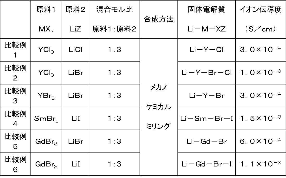
- Comparative Examples 1 to 6 (Preparation of solid electrolyte material)
- the raw material powders were weighed in an argon atmosphere having a dew point of ⁇ 60° C. or lower.
- Example 1 exhibited higher ionic conductivity than the solid electrolyte materials of Examples 9 and 10. Since calcination at 200° C. is lower than the temperature at which a solid electrolyte having high ionic conductivity is generated, it is considered that high ionic conductivity cannot be realized. On the other hand, it is considered that the target solid electrolyte was not produced because the NH 4 Cl sublimated in the firing at 500° C.
- Examples 1 to 8 have the same ionic conductivity as the solid electrolyte materials synthesized by the mechanochemical milling reaction of Comparative Examples 1 to 6.
- the solid electrolyte material synthesized by the manufacturing method of the present disclosure exhibits high lithium ion conductivity.
- the manufacturing method of this indication is a simple method and is a method with high industrial productivity.
- the production method of the present disclosure can be easily synthesized from an inexpensive solid-phase reaction of M 2 O 3 and NH 4 X, and thus the cost can be further reduced.
- the manufacturing method of the present disclosure can be used, for example, as a method for manufacturing a solid electrolyte material.
- the solid electrolyte material manufactured by the manufacturing method of the present disclosure can be used as, for example, an all-solid lithium secondary battery.
Landscapes
- Chemical & Material Sciences (AREA)
- Organic Chemistry (AREA)
- Inorganic Chemistry (AREA)
- Geology (AREA)
- Condensed Matter Physics & Semiconductors (AREA)
- Engineering & Computer Science (AREA)
- Manufacturing & Machinery (AREA)
- General Physics & Mathematics (AREA)
- General Chemical & Material Sciences (AREA)
- Chemical Kinetics & Catalysis (AREA)
- Life Sciences & Earth Sciences (AREA)
- Electrochemistry (AREA)
- Physics & Mathematics (AREA)
- Conductive Materials (AREA)
- Secondary Cells (AREA)
- Compounds Of Alkaline-Earth Elements, Aluminum Or Rare-Earth Metals (AREA)
Abstract
Description
(実施の形態1)
図1は、実施の形態1における製造方法の一例を示すフローチャートである。
実施の形態1における製造方法は、焼成工程S1000を包含する。
焼成工程S1000は、混合材料を、不活性ガス雰囲気下で、焼成する工程である。
ここで、焼成工程S1000で焼成される混合材料は、M2O3とNH4XとLiZとが混合された材料である。
また、Zは、Cl、Br、IおよびFからなる群より選択される少なくとも1種の元素である。
以上の構成によれば、より高いイオン伝導度を有するハロゲン化物を製造できる。
以上の構成によれば、より高いイオン伝導度を有するハロゲン化物を製造できる。
例えば、M2O3とNH4XとLiX(すなわち、上述のLiZにおけるZがXであるもの)から、Li3MX6を作製する場合には、系全体として、下記の式(1)に示される反応が起こると考えられる。
M2O3+12NH4X+6LiX
→ 2Li3MX6+12NH3+6HX+3H2O・・・(1)
以上の構成によれば、焼成温度を200℃以上とすることで、M2O3とNH4XとLiZとを反応させることができる。さらに、焼成温度を650℃以下とすることで、固相反応により生成したハロゲン化物の熱分解を抑制できる。
Y2O3+12NH4Cl+6LiBr
→ 2Li3YBr3Cl3+12NH3+3HBr+3HCl+3H2O …(2)
以上の構成によれば、工業的に生産性の高い方法で、より高いイオン伝導度を有するハロゲン化物を製造することができる。すなわち、焼成時間を1時間以上とすることで、M2O3とNH4XとLiZとを十分に反応させることができる。さらに、焼成時間を72時間以下とすることで、焼成物であるハロゲン化物の揮発を抑制でき、所望の構成元素の組成比を有するハロゲン化物を得ることができる(すなわち、組成ずれを抑制できる)。これらにより、焼成物であるハロゲン化物のイオン伝導度を、より高めることができる。すなわち、例えば、より良質なハロゲン化物の固体電解質を得ることができる。
図2に示されるように、実施の形態1における製造方法は、混合工程S1100を、さらに包含してもよい。
混合工程S1100は、焼成工程S1000よりも前に、実行される工程である。
混合工程S1100は、原料となるM2O3とNH4XとLiZとが混合されることで、混合材料(すなわち、焼成工程S1000において焼成される材料)が得られる工程である。
図3に示されるように、実施の形態1における製造方法は、準備工程S1200を、さらに包含してもよい。
準備工程S1200は、混合工程S1100よりも前に、実行される工程である。
準備工程S1200は、M2O3およびNH4XおよびLiZなどの原料(すなわち、混合工程S1100において混合される材料)が準備される工程である。
以下、実施の形態2が説明される。上述の実施の形態1と重複する説明は、適宜、省略される。
図4は、実施の形態2における製造方法の一例を示すフローチャートである。
実施の形態2における製造方法は、上述の実施の形態1における製造方法の特徴に加えて、下記の特徴をさらに備える。
第2焼成工程S1002は、第1焼成工程S1001の後に実行される工程である。
第1焼成工程S1001においては、混合材料は、第1焼成温度T1で、焼成される。
第2焼成工程S1002においては、混合材料は、第2焼成温度T2で、焼成される。
このとき、T1<T2、が満たされる。
以上の構成によれば、工業的に生産性の高い方法で、より高いイオン伝導度を有するハロゲン化物を製造することができる。すなわち、第1焼成温度T1を200℃以上とすることで、M2O3とNH4Xとを十分に反応させることができる。さらに、第1焼成温度T1を330℃未満とすることで、NH4Xの昇華を抑制できる(例えば、NH4Clの昇華点は335℃である)。これらにより、焼成物であるハロゲン化物のイオン伝導度を高めることができる。すなわち、例えば、良質なハロゲン化物の固体電解質を得ることができる。
以上の構成によれば、工業的に生産性の高い方法で、より高いイオン伝導度を有するハロゲン化物を製造することができる。すなわち、第1焼成温度T1を200℃以上とすることで、M2O3とNH4Xとを十分に反応させることができる。さらに、第1焼成温度T1を390℃未満とすることで、NH4Xの昇華を抑制できる(例えば、NH4Brの昇華点は396℃である)。これらにより、焼成物であるハロゲン化物のイオン伝導度を高めることができる。すなわち、例えば、良質なハロゲン化物の固体電解質を得ることができる。
以上の構成によれば、工業的に生産性の高い方法で、より高いイオン伝導度を有するハロゲン化物を製造することができる。すなわち、第2焼成温度T2を390℃以上とすることで、「M2O3とNH4Xとの反応による生成物」とLiZとを、より十分に反応させることができる。これにより、焼成物であるハロゲン化物の結晶性を、より高くできる。さらに、第2焼成温度T2を650℃以下とすることで、固相反応により生成したハロゲン化物の熱分解を抑制できる。これらにより、焼成物であるハロゲン化物のイオン伝導度を高めることができる。すなわち、例えば、良質なハロゲン化物の固体電解質を得ることができる。
以上の構成によれば、工業的に生産性の高い方法で、より高いイオン伝導度を有するハロゲン化物を製造することができる。すなわち、第1焼成温度T1を200℃以上とすることで、M2O3とNH4Xとを十分に反応させることができる。さらに、第1焼成温度T1を550℃未満とすることで、NH4Xの昇華を抑制できる(例えば、NH4Iの昇華点は551℃である)。これらにより、焼成物であるハロゲン化物のイオン伝導度を高めることができる。すなわち、例えば、良質なハロゲン化物の固体電解質を得ることができる。
以上の構成によれば、工業的に生産性の高い方法で、より高いイオン伝導度を有するハロゲン化物を製造することができる。すなわち、第2焼成温度T2を550℃以上とすることで、「M2O3とNH4Xとの反応による生成物」とLiZとを、より十分に反応させることができる。これにより、焼成物であるハロゲン化物の結晶性を、より高くできる。さらに、第2焼成温度T2を650℃以下とすることで、固相反応により生成したハロゲン化物の熱分解を抑制できる。これらにより、焼成物であるハロゲン化物のイオン伝導度を高めることができる。すなわち、例えば、良質なハロゲン化物の固体電解質を得ることができる。
以上の構成によれば、工業的に生産性の高い方法で、より高いイオン伝導度を有するハロゲン化物を製造することができる。すなわち、第1焼成温度T1を200℃以上とすることで、M2O3とNH4Xとを十分に反応させることができる。さらに、第1焼成温度T1を230℃未満とすることで、NH4Xの昇華を抑制できる(例えば、NH4Fの昇華点は238℃である)。これらにより、焼成物であるハロゲン化物のイオン伝導度を高めることができる。すなわち、例えば、良質なハロゲン化物の固体電解質を得ることができる。
以上の構成によれば、工業的に生産性の高い方法で、より高いイオン伝導度を有するハロゲン化物を製造することができる。すなわち、第2焼成温度T2を230℃以上とすることで、「M2O3とNH4Xとの反応による生成物」とLiZとを、より十分に反応させることができる。これにより、焼成物であるハロゲン化物の結晶性を、より高くできる。さらに、第2焼成温度T2を650℃以下とすることで、固相反応により生成したハロゲン化物の熱分解を抑制できる。これらにより、焼成物であるハロゲン化物のイオン伝導度を高めることができる。すなわち、例えば、良質なハロゲン化物の固体電解質を得ることができる。
図5に示されるように、第1焼成工程S1001においては、混合材料は、第1焼成時間P1の間、焼成されてもよい。
また、第2焼成工程S1002においては、混合材料は、第2焼成時間P2の間、焼成されてもよい。
このとき、P1>P2、が満たされてもよい。
以上の構成によれば、工業的に生産性の高い方法で、より高いイオン伝導度を有するハロゲン化物を製造することができる。すなわち、第1焼成時間P1を1時間以上とすることで、M2O3とNH4Xとを十分に反応させることができる。さらに、第1焼成時間P1を72時間以下とすることで、「M2O3とNH4Xとの反応による生成物」の揮発を抑制でき、所望の構成元素の組成比を有するハロゲン化物を得ることができる(すなわち、組成ずれを抑制できる)。これらにより、焼成物であるハロゲン化物のイオン伝導度を、より高めることができる。すなわち、例えば、より良質なハロゲン化物の固体電解質を得ることができる。
以上の構成によれば、工業的に生産性の高い方法で、より高いイオン伝導度を有するハロゲン化物を製造することができる。すなわち、第2焼成時間P2を1時間以上とすることで、「M2O3とNH4Xとの反応による生成物」とLiZとを十分に反応させることができる。さらに、第2焼成時間P2を72時間以下とすることで、焼成物であるハロゲン化物の揮発を抑制でき、所望の構成元素の組成比を有するハロゲン化物を得ることができる(すなわち、組成ずれを抑制できる)。これらにより、焼成物であるハロゲン化物のイオン伝導度を、より高めることができる。すなわち、例えば、より良質なハロゲン化物の固体電解質を得ることができる。
なお、以下の例示においては、本開示の製造方法により製造されるハロゲン化物は、固体電解質材料として製造され、評価されている。
(固体電解質材料の作製)
露点-60℃以下のアルゴン雰囲気で、Y2O3とNH4ClとLiBrとを、モル比でY2O3:NH4Cl:LiBr=1:13.2:6となるように秤量した(すなわち、NH4ClがY2O3に対して10mol%過剰となるように秤量した)。これらをメノウ製乳鉢で粉砕して混合した。その後、アルミナ製るつぼに入れて、T1=T2=300℃として、窒素雰囲気下で15時間保持した。
焼成後、メノウ製乳鉢により粉砕し、実施例1の固体電解質材料を作製した。
図6は、イオン伝導度の評価方法を示す模式図である。
加圧成形用ダイス200は、電子的に絶縁性のポリカーボネート製の枠型201と、電子伝導性のステンレス製のパンチ上部203およびパンチ下部202とから構成される。
露点-60℃以下のドライ雰囲気で、実施例1の固体電解質材料の粉末である固体電解質粉末100を加圧成形用ダイス200に充填し、300MPaで一軸加圧し、実施例1の伝導度測定セルを作製した。
σ=(RSE×S/t)-1 ・・・・ (3)
(固体電解質材料の作製)
露点-60℃以下のアルゴン雰囲気で、Y2O3とNH4ClとLiBrとを、モル比でY2O3:NH4Cl:LiBr=1:13.2:6となるように秤量した(NH4ClをY2O3に対して化学量論比よりも10mol%過剰量を秤量となるように秤量した)。これらをメノウ製乳鉢で粉砕して混合した。その後、アルミナ製るつぼに入れて、T1=200℃として、窒素雰囲気下で15時間保持した後で、T2=500℃として、窒素雰囲気下で1時間保持した。
焼成後、メノウ製乳鉢により粉砕し、実施例2の固体電解質材料を作製した。
上記の実施例1と同様の方法で、実施例2の伝導度測定セルを作製し、イオン伝導度の測定を実施した。
(固体電解質材料の作製)
実施例3~5においては、露点-60℃以下のアルゴン雰囲気下で、原料粉末を秤量した。
実施例3においては、Y2O3とNH4ClとLiClとを、モル比でY2O3:NH4Cl:LiCl=1:13.2:6となるように秤量した。
実施例4においては、Y2O3とNH4BrとLiClとを、モル比でY2O3:NH4Br:LiCl=1:13.2:6となるように秤量した。
実施例5においては、Y2O3とNH4BrとLiBrとを、モル比でY2O3:NH4Br:LiBr=1:13.2:6となるように秤量した。
その後、アルミナ製るつぼに入れて、T1=200℃として、窒素雰囲気下で15時間保持した後で、T2=500℃として、窒素雰囲気下で1時間保持した。
焼成後、メノウ製乳鉢により粉砕し、実施例3~5の固体電解質材料を作製した。
上記の実施例1と同様の方法で、実施例3~5の伝導度測定セルを作製し、イオン伝導度の測定を実施した。
(固体電解質材料の作製)
実施例6~8においては、露点-60℃以下のアルゴン雰囲気下で、原料粉末を秤量した。
実施例6においては、Sm2O3とNH4BrとLiIとを、モル比でSm2O3:NH4Br:LiI=1:13.2:6となるように秤量した。
実施例7においては、Gd2O3とNH4BrとLiClとを、モル比でGd2O3:NH4Br:LiCl=1:13.2:6となるように秤量した。
実施例8においては、Gd2O3とNH4BrとLiBrとを、モル比でGd2O3:NH4Br:LiBr=1:13.2:6となるように秤量した。
その後、アルミナ製るつぼに入れて、T1=200℃として、窒素雰囲気下で15時間保持した後で、T2=500℃として、窒素雰囲気下で1時間保持した。
焼成後、メノウ製乳鉢により粉砕し、実施例6~8の固体電解質材料を作製した。
上記の実施例1と同様の方法で、実施例6~8の伝導度測定セルを作製し、イオン伝導度の測定を実施した。
(固体電解質材料の作製)
露点-60℃以下のアルゴン雰囲気で、Y2O3とNH4ClとLiBrとを、モル比でY2O3:NH4Cl:LiBr=1:13.2:6となるように秤量した。これらをメノウ製乳鉢で粉砕して混合した。
実施例10においては、その後、アルミナ製るつぼに入れて、T1=T2=500℃として、窒素雰囲気下で15時間保持した。
焼成後、メノウ製乳鉢により粉砕し、実施例9および実施例10の固体電解質材料を作製した。
上記の実施例1と同様の方法で、実施例9および実施例10の伝導度測定セルを作製し、イオン伝導度の測定を実施した。
上述の実施例1~10における各構成と各評価結果とが、表1に示される。

(固体電解質材料の作製)
比較例1~6においては、露点-60℃以下のアルゴン雰囲気下で、原料粉末を秤量した。
比較例1においては、YCl3とLiClとを、モル比でYCl3:LiCl=1:3となるように秤量した。
比較例2においては、YCl3とLiBrとを、モル比でYCl3:LiBr=1:3となるように秤量した。
比較例3においては、YBr3とLiBrとを、モル比でYBr3:LiBr=1:3となるように秤量した。
比較例4においては、SmBr3とLiIとを、モル比でSmBr3:LiI=1:3となるように秤量した。
比較例5においては、GdBr3とLiBrとを、モル比でGdBr3:LiBr=1:3となるように秤量した。
比較例6においては、GdBr3とLiIとを、モル比でGdBr3:LiI=1:3となるように秤量した。
これらをメノウ製乳鉢で粉砕して混合した後、メカノケミカルミリングの方法を用いて原料粉同士を混合・粉砕・反応させることにより、比較例1~6のそれぞれの固体電解質材料を作製した。
上記の実施例1と同様の方法で、比較例1~6のそれぞれの伝導度測定セルを作製し、イオン伝導度の測定を実施した。
上述の比較例1~6における各構成と各評価結果とが、表2に示される。
実施例1の固体電解質材料は、実施例9および実施例10の固体電解質材料よりも高いイオン伝導度を示した。200℃の焼成では、高いイオン伝導率を有する固体電解質が生成する温度よりも低いため、高いイオン伝導率を実現できていないと考えられる。一方、500℃の焼成では、NH4Clが昇華したため、目的の固体電解質が生成していないと考えられる。
200 加圧成形用ダイス
201 枠型
202 パンチ下部
203 パンチ上部
Claims (13)
- M2O3とNH4XとLiZとが混合された材料である混合材料を、不活性ガス雰囲気下で、焼成する焼成工程、
を包含し、
前記Mは、Y、ランタノイドおよびScからなる群より選択される少なくとも1種の元素を含み、
前記Xは、Cl、Br、IおよびFからなる群より選択される少なくとも1種の元素であり、
前記Zは、Cl、Br、IおよびFからなる群より選択される少なくとも1種の元素である、ハロゲン化物の製造方法。 - 前記焼成工程においては、前記混合材料は、200℃以上かつ650℃以下で、焼成される、請求項1に記載の製造方法。
- 前記焼成工程においては、前記混合材料は、1時間以上かつ72時間以下、焼成される、請求項1または2に記載の製造方法。
- 前記焼成工程は、第1焼成工程と、前記第1焼成工程の後に実行される第2焼成工程と、を含み、
前記第1焼成工程においては、前記混合材料は、第1焼成温度T1で、焼成され、
前記第2焼成工程においては、前記混合材料は、第2焼成温度T2で、焼成され、
T1<T2、が満たされる、請求項1に記載の製造方法。 - 前記Xは、Clを含み、
200℃≦T1<330℃、が満たされ、
330℃≦T2≦650℃、が満たされる、請求項4に記載の製造方法。 - 前記Xは、Brを含み、
200℃≦T1<390℃、が満たされ、
390℃≦T2≦650℃、が満たされる、請求項4に記載の製造方法。 - 前記Xは、Iを含み、
200℃≦T1<550℃、が満たされ、
550℃≦T2≦650℃、が満たされる、請求項4に記載の製造方法。 - 前記Xは、Fを含み、
200℃≦T1<230℃、が満たされ、
230℃≦T2≦650℃、が満たされる、請求項4に記載の製造方法。 - 前記第1焼成工程においては、前記混合材料は、第1焼成時間P1の間、焼成され、
前記第2焼成工程においては、前記混合材料は、第2焼成時間P2の間、焼成され、
P1>P2、が満たされる、請求項4から8のいずれか1項に記載の製造方法。 - 前記第1焼成時間P1は、1時間以上かつ72時間以下である、請求項9に記載の製造方法。
- 前記第2焼成時間P2は、1時間以上かつ72時間以下である、請求項9または10に記載の製造方法。
- 前記Mは、Y、SmおよびGdからなる群より選択される少なくとも1種の元素である、請求項1から11のいずれか1項に記載の製造方法。
- 前記Xは、Cl、BrおよびIからなる群より選択される少なくとも1種の元素であり、
前記Zは、Cl、BrおよびIからなる群より選択される少なくとも1種の元素である、請求項1から7および9から12のいずれか1項に記載の製造方法。
Priority Applications (4)
| Application Number | Priority Date | Filing Date | Title |
|---|---|---|---|
| EP19904166.6A EP3904291A4 (en) | 2018-12-28 | 2019-06-26 | HALIDE PRODUCTION PROCESS |
| JP2020562323A JP7186405B2 (ja) | 2018-12-28 | 2019-06-26 | ハロゲン化物の製造方法 |
| CN201980061920.5A CN112739653B (zh) | 2018-12-28 | 2019-06-26 | 卤化物的制造方法 |
| US17/321,481 US11981580B2 (en) | 2018-12-28 | 2021-05-16 | Method for producing halides |
Applications Claiming Priority (2)
| Application Number | Priority Date | Filing Date | Title |
|---|---|---|---|
| JP2018247312 | 2018-12-28 | ||
| JP2018-247312 | 2018-12-28 |
Related Child Applications (1)
| Application Number | Title | Priority Date | Filing Date |
|---|---|---|---|
| US17/321,481 Continuation US11981580B2 (en) | 2018-12-28 | 2021-05-16 | Method for producing halides |
Publications (1)
| Publication Number | Publication Date |
|---|---|
| WO2020136956A1 true WO2020136956A1 (ja) | 2020-07-02 |
Family
ID=71127853
Family Applications (1)
| Application Number | Title | Priority Date | Filing Date |
|---|---|---|---|
| PCT/JP2019/025440 Ceased WO2020136956A1 (ja) | 2018-12-28 | 2019-06-26 | ハロゲン化物の製造方法 |
Country Status (5)
| Country | Link |
|---|---|
| US (1) | US11981580B2 (ja) |
| EP (1) | EP3904291A4 (ja) |
| JP (1) | JP7186405B2 (ja) |
| CN (1) | CN112739653B (ja) |
| WO (1) | WO2020136956A1 (ja) |
Cited By (9)
| Publication number | Priority date | Publication date | Assignee | Title |
|---|---|---|---|---|
| JPWO2021199890A1 (ja) * | 2020-03-31 | 2021-10-07 | ||
| JPWO2021199889A1 (ja) * | 2020-03-31 | 2021-10-07 | ||
| JPWO2022249761A1 (ja) * | 2021-05-28 | 2022-12-01 | ||
| US11522217B2 (en) | 2020-04-14 | 2022-12-06 | Saint-Gobain Ceramics & Plastics, Inc. | Electrolyte material and methods of forming |
| US11637315B2 (en) | 2020-08-07 | 2023-04-25 | Saint-Gobain Ceramics & Plastics, Inc. | Electrolyte material and methods of forming |
| US11664531B2 (en) | 2020-04-14 | 2023-05-30 | Saint-Gobain Ceramics & Plastics, Inc. | Ion conductive material including complex metal halide, electrolyte including the same, and methods of forming the same |
| WO2023181542A1 (ja) | 2022-03-24 | 2023-09-28 | パナソニックIpマネジメント株式会社 | ハロゲン化物材料の製造方法およびハロゲン化物材料 |
| JP2023543112A (ja) * | 2021-05-17 | 2023-10-13 | サン-ゴバン セラミックス アンド プラスティクス,インコーポレイティド | 電解質材料及び形成する方法 |
| KR102961317B1 (ko) * | 2021-05-17 | 2026-05-08 | 세인트-고바인 세라믹스 앤드 플라스틱스, 인크. | 전해질 물질 및 형성 방법 |
Families Citing this family (2)
| Publication number | Priority date | Publication date | Assignee | Title |
|---|---|---|---|---|
| EP3904290A4 (en) * | 2018-12-28 | 2022-03-02 | Panasonic Intellectual Property Management Co., Ltd. | HALOGEN MANUFACTURING PROCESS |
| CN116443914B (zh) * | 2023-03-26 | 2025-03-18 | 长江大学 | 一种卤化物固态电解质的制备方法及其应用 |
Citations (1)
| Publication number | Priority date | Publication date | Assignee | Title |
|---|---|---|---|---|
| CN105254184A (zh) * | 2015-11-27 | 2016-01-20 | 宁波大学 | 一种稀土离子掺杂的Li3YCl6微晶玻璃及其制备方法 |
Family Cites Families (10)
| Publication number | Priority date | Publication date | Assignee | Title |
|---|---|---|---|---|
| US3153570A (en) | 1960-03-09 | 1964-10-20 | Dow Chemical Co | Production of rare earth chlorides of high purity |
| FR2315530A1 (fr) * | 1975-06-25 | 1977-01-21 | United States Radium Corp | Composition phosphorescente et son procede d'obtention |
| JP2866891B2 (ja) * | 1990-06-21 | 1999-03-08 | 神島化学工業株式会社 | 多結晶透明イットリウムアルミニウムガーネット焼結体及びその製造方法 |
| JP2009173489A (ja) * | 2008-01-24 | 2009-08-06 | Showa Denko Kk | 窒化物の製造方法 |
| CN101339994B (zh) * | 2008-09-01 | 2010-12-01 | 甘肃大象能源科技有限公司 | 多位掺杂型磷酸铁锂正极材料制备方法及其应用 |
| JP2012132000A (ja) * | 2010-12-02 | 2012-07-12 | Niigata Univ | 結晶性物質の製造方法 |
| CN104119911A (zh) * | 2014-06-30 | 2014-10-29 | 彩虹集团电子股份有限公司 | 一种高光效led用铝酸盐荧光粉的制备方法 |
| CN106745163B (zh) * | 2015-11-24 | 2018-10-19 | 有研稀土新材料股份有限公司 | 高纯无水复合稀土卤化物及其制备方法 |
| JP6934626B2 (ja) | 2016-08-04 | 2021-09-15 | パナソニックIpマネジメント株式会社 | 固体電解質材料、および、電池 |
| CN107516739A (zh) * | 2017-08-08 | 2017-12-26 | 西安交通大学 | 一种利用缺陷调控法制备锂离子电池电极材料的方法 |
-
2019
- 2019-06-26 CN CN201980061920.5A patent/CN112739653B/zh not_active Expired - Fee Related
- 2019-06-26 JP JP2020562323A patent/JP7186405B2/ja active Active
- 2019-06-26 WO PCT/JP2019/025440 patent/WO2020136956A1/ja not_active Ceased
- 2019-06-26 EP EP19904166.6A patent/EP3904291A4/en not_active Withdrawn
-
2021
- 2021-05-16 US US17/321,481 patent/US11981580B2/en active Active
Patent Citations (1)
| Publication number | Priority date | Publication date | Assignee | Title |
|---|---|---|---|---|
| CN105254184A (zh) * | 2015-11-27 | 2016-01-20 | 宁波大学 | 一种稀土离子掺杂的Li3YCl6微晶玻璃及其制备方法 |
Non-Patent Citations (3)
| Title |
|---|
| ANDREAS BOHNSACK, BALZER GERT, GÜDEL HANS‐U., WICKLEDER MATHIAS S., MEYER GERD: "Ternary Halides of the A3 MX 6 Type. VI. Ternary Chlorides of the Rare- Earth Elements with Lithium , Li", JOURNAL OF INORGANIC AND GENERAL CHEMISTRY, vol. 623, 1 July 1997 (1997-07-01), pages 1067 - 1073, XP055600040, DOI: 10.1002/chin.199739018 * |
| BOHNSACK, ANDREAS ET AL.: "Ternary Halides of the A3 MX 6Type. VII. The Bromides Li3MBr6(M=Sm-Lu, Y): Synthesis", CRYSTAL STRUCTURE, JOURNAL OF INORGANIC AND GENERAL CHEMISTRY, vol. 623, 1997, pages 1352 - 1356, XP055600030, DOI: 10.1002/zaac.19976230905 * |
| EWA KOWALCZYK ,RYSZARD DIDUSZKO, ZBIGNIEW KOWALCYZYK ,TOMASZ LESZCZYŃSKI: "Studies on the reaction of ammonium fluoride with lithium carbonate and yttrium oxide", THERMOCHIMICA ACTA, vol. 265, 1 November 1995 (1995-11-01), pages 189 - 195, XP055722388, DOI: 10.1016/0040-6031(95)02426-3 * |
Cited By (21)
| Publication number | Priority date | Publication date | Assignee | Title |
|---|---|---|---|---|
| JPWO2021199889A1 (ja) * | 2020-03-31 | 2021-10-07 | ||
| JP7702662B2 (ja) | 2020-03-31 | 2025-07-04 | パナソニックIpマネジメント株式会社 | ハロゲン化物の製造方法 |
| JP7702661B2 (ja) | 2020-03-31 | 2025-07-04 | パナソニックIpマネジメント株式会社 | ハロゲン化物の製造方法 |
| JPWO2021199890A1 (ja) * | 2020-03-31 | 2021-10-07 | ||
| US11522217B2 (en) | 2020-04-14 | 2022-12-06 | Saint-Gobain Ceramics & Plastics, Inc. | Electrolyte material and methods of forming |
| US11664531B2 (en) | 2020-04-14 | 2023-05-30 | Saint-Gobain Ceramics & Plastics, Inc. | Ion conductive material including complex metal halide, electrolyte including the same, and methods of forming the same |
| US11978847B2 (en) | 2020-04-14 | 2024-05-07 | Saint-Gobain Ceramics & Plastics, Inc. | Ion conductive material, electrolyte including ion conductive material, and methods of forming |
| US11973186B2 (en) | 2020-04-14 | 2024-04-30 | Saint-Gobain Ceramics & Plastics, Inc. | Ion conductive material including halide material, electrolyte including the same, and methods of forming the same |
| US11978849B2 (en) | 2020-08-07 | 2024-05-07 | Saint-Gobain Ceramics & Plastics, Inc. | Electrolyte material and methods of forming |
| US11637315B2 (en) | 2020-08-07 | 2023-04-25 | Saint-Gobain Ceramics & Plastics, Inc. | Electrolyte material and methods of forming |
| JP7534499B2 (ja) | 2020-08-07 | 2024-08-14 | サン-ゴバン セラミックス アンド プラスティクス,インコーポレイティド | 電解質材料及び形成方法 |
| JP2023162164A (ja) * | 2020-08-07 | 2023-11-08 | サン-ゴバン セラミックス アンド プラスティクス,インコーポレイティド | 電解質材料及び形成方法 |
| US11848414B2 (en) | 2021-05-17 | 2023-12-19 | Saint-Gobain Ceramics & Plastics, Inc. | Electrolyte material and methods of forming |
| JP2023543112A (ja) * | 2021-05-17 | 2023-10-13 | サン-ゴバン セラミックス アンド プラスティクス,インコーポレイティド | 電解質材料及び形成する方法 |
| JP2024138315A (ja) * | 2021-05-17 | 2024-10-08 | サン-ゴバン セラミックス アンド プラスティクス,インコーポレイティド | 電解質材料及び形成する方法 |
| US12308384B2 (en) | 2021-05-17 | 2025-05-20 | Saint-Gobain Ceramics & Plastics, Inc. | Electrolyte material and methods of forming |
| KR102961317B1 (ko) * | 2021-05-17 | 2026-05-08 | 세인트-고바인 세라믹스 앤드 플라스틱스, 인크. | 전해질 물질 및 형성 방법 |
| WO2022249761A1 (ja) * | 2021-05-28 | 2022-12-01 | パナソニックIpマネジメント株式会社 | ハロゲン化物の製造方法 |
| JPWO2022249761A1 (ja) * | 2021-05-28 | 2022-12-01 | ||
| JP7825184B2 (ja) | 2021-05-28 | 2026-03-06 | パナソニックIpマネジメント株式会社 | ハロゲン化物の製造方法 |
| WO2023181542A1 (ja) | 2022-03-24 | 2023-09-28 | パナソニックIpマネジメント株式会社 | ハロゲン化物材料の製造方法およびハロゲン化物材料 |
Also Published As
| Publication number | Publication date |
|---|---|
| JPWO2020136956A1 (ja) | 2021-11-18 |
| US11981580B2 (en) | 2024-05-14 |
| EP3904291A4 (en) | 2022-03-02 |
| EP3904291A1 (en) | 2021-11-03 |
| CN112739653B (zh) | 2023-03-28 |
| CN112739653A (zh) | 2021-04-30 |
| JP7186405B2 (ja) | 2022-12-09 |
| US20210269324A1 (en) | 2021-09-02 |
Similar Documents
| Publication | Publication Date | Title |
|---|---|---|
| JP7186405B2 (ja) | ハロゲン化物の製造方法 | |
| JP7365599B2 (ja) | ハロゲン化物の製造方法 | |
| JP7365600B2 (ja) | ハロゲン化物の製造方法 | |
| JP7186404B2 (ja) | ハロゲン化物の製造方法 | |
| JP7357299B2 (ja) | ハロゲン化物の製造方法 | |
| JP7650006B2 (ja) | ハロゲン化物の製造方法 | |
| JP7378039B2 (ja) | ハロゲン化物の製造方法 | |
| JP7702661B2 (ja) | ハロゲン化物の製造方法 | |
| JP7702662B2 (ja) | ハロゲン化物の製造方法 | |
| JP7650007B2 (ja) | ハロゲン化物の製造方法 | |
| JP7650005B2 (ja) | ハロゲン化物の製造方法 |
Legal Events
| Date | Code | Title | Description |
|---|---|---|---|
| 121 | Ep: the epo has been informed by wipo that ep was designated in this application |
Ref document number: 19904166 Country of ref document: EP Kind code of ref document: A1 |
|
| ENP | Entry into the national phase |
Ref document number: 2020562323 Country of ref document: JP Kind code of ref document: A |
|
| NENP | Non-entry into the national phase |
Ref country code: DE |
|
| ENP | Entry into the national phase |
Ref document number: 2019904166 Country of ref document: EP Effective date: 20210728 |
|
| WWW | Wipo information: withdrawn in national office |
Ref document number: 2019904166 Country of ref document: EP |