WO2020137083A1 - 冷却ユニット、対物レンズモジュール、半導体検査装置、半導体検査方法 - Google Patents
冷却ユニット、対物レンズモジュール、半導体検査装置、半導体検査方法 Download PDFInfo
- Publication number
- WO2020137083A1 WO2020137083A1 PCT/JP2019/039879 JP2019039879W WO2020137083A1 WO 2020137083 A1 WO2020137083 A1 WO 2020137083A1 JP 2019039879 W JP2019039879 W JP 2019039879W WO 2020137083 A1 WO2020137083 A1 WO 2020137083A1
- Authority
- WO
- WIPO (PCT)
- Prior art keywords
- semiconductor device
- cooling unit
- space
- jacket
- objective lens
- Prior art date
- Legal status (The legal status is an assumption and is not a legal conclusion. Google has not performed a legal analysis and makes no representation as to the accuracy of the status listed.)
- Ceased
Links
Images


Classifications
-
- G—PHYSICS
- G01—MEASURING; TESTING
- G01R—MEASURING ELECTRIC VARIABLES; MEASURING MAGNETIC VARIABLES
- G01R31/00—Arrangements for testing electric properties; Arrangements for locating electric faults; Arrangements for electrical testing characterised by what is being tested not provided for elsewhere
- G01R31/28—Testing of electronic circuits, e.g. by signal tracer
- G01R31/2851—Testing of integrated circuits [IC]
- G01R31/2855—Environmental, reliability or burn-in testing
- G01R31/2872—Environmental, reliability or burn-in testing related to electrical or environmental aspects, e.g. temperature, humidity, vibration, nuclear radiation
- G01R31/2874—Environmental, reliability or burn-in testing related to electrical or environmental aspects, e.g. temperature, humidity, vibration, nuclear radiation related to temperature
- G01R31/2877—Environmental, reliability or burn-in testing related to electrical or environmental aspects, e.g. temperature, humidity, vibration, nuclear radiation related to temperature related to cooling
-
- G—PHYSICS
- G01—MEASURING; TESTING
- G01R—MEASURING ELECTRIC VARIABLES; MEASURING MAGNETIC VARIABLES
- G01R31/00—Arrangements for testing electric properties; Arrangements for locating electric faults; Arrangements for electrical testing characterised by what is being tested not provided for elsewhere
- G01R31/26—Testing of individual semiconductor devices
-
- G—PHYSICS
- G01—MEASURING; TESTING
- G01R—MEASURING ELECTRIC VARIABLES; MEASURING MAGNETIC VARIABLES
- G01R31/00—Arrangements for testing electric properties; Arrangements for locating electric faults; Arrangements for electrical testing characterised by what is being tested not provided for elsewhere
- G01R31/28—Testing of electronic circuits, e.g. by signal tracer
- G01R31/2851—Testing of integrated circuits [IC]
- G01R31/2855—Environmental, reliability or burn-in testing
- G01R31/286—External aspects, e.g. related to chambers, contacting devices or handlers
- G01R31/2868—Complete testing stations; systems; procedures; software aspects
-
- G—PHYSICS
- G01—MEASURING; TESTING
- G01R—MEASURING ELECTRIC VARIABLES; MEASURING MAGNETIC VARIABLES
- G01R31/00—Arrangements for testing electric properties; Arrangements for locating electric faults; Arrangements for electrical testing characterised by what is being tested not provided for elsewhere
- G01R31/28—Testing of electronic circuits, e.g. by signal tracer
- G01R31/302—Contactless testing
-
- H—ELECTRICITY
- H10—SEMICONDUCTOR DEVICES; ELECTRIC SOLID-STATE DEVICES NOT OTHERWISE PROVIDED FOR
- H10W—GENERIC PACKAGES, INTERCONNECTIONS, CONNECTORS OR OTHER CONSTRUCTIONAL DETAILS OF DEVICES COVERED BY CLASS H10
- H10W40/00—Arrangements for thermal protection or thermal control
- H10W40/40—Arrangements for thermal protection or thermal control involving heat exchange by flowing fluids
- H10W40/47—Arrangements for thermal protection or thermal control involving heat exchange by flowing fluids by flowing liquids, e.g. forced water cooling
Definitions
- One aspect of the present disclosure relates to a cooling unit, an objective lens module, a semiconductor inspection device, and a semiconductor inspection method.
- the cooling unit described in Patent Document 1 As a cooling unit used in the inspection of semiconductor devices, for example, the one described in Patent Document 1 is known.
- the cooling unit described in Patent Document 1 is used for observing a driven semiconductor device while cooling it.
- the semiconductor device In the cooling unit described in Patent Document 1, the semiconductor device is cooled by injecting a cooling liquid onto the semiconductor device.
- an aspect of the present disclosure is to provide a cooling unit and an objective lens module having enhanced cooling performance, a semiconductor inspection apparatus including such a cooling unit, and a semiconductor inspection capable of inspecting a semiconductor device while appropriately cooling it.
- the purpose is to provide a method.
- a cooling unit is a cooling unit used in inspection of a semiconductor device, and includes a jacket for radiating heat of the semiconductor device, and the jacket has a light for transmitting light from the semiconductor device.
- the jacket is provided with a passage part, and the jacket has a space defining surface facing the semiconductor device and defining a space between the semiconductor device and the semiconductor device in a state where the light passage part faces the semiconductor device.
- a supply channel through which the supplied fluid flows is provided.
- this cooling unit for inspection of semiconductor devices, for example, arrange the cooling unit so that the light passage part faces the semiconductor device and a space is defined between the space defining surface and the semiconductor device. Then, the light emitted from the driving semiconductor device and passing through the light passage portion is detected while flowing the fluid into the space through the supply channel.
- the semiconductor device can be effectively cooled by flowing the fluid into the space defined between the jacket and the semiconductor device. This is because the heat of the semiconductor device is removed by the fluid and the heat of the semiconductor device is efficiently transferred to the jacket through the fluid. Therefore, according to this cooling unit, high cooling performance can be realized.
- the jacket may be further provided with a discharge passage through which the fluid discharged from the space flows.
- the fluid can be flown into the space through the supply flow path and the discharge flow path, and the semiconductor device can be cooled more effectively.
- the jacket may be further provided with a coolant channel through which a coolant for cooling the jacket flows.
- the jacket can be cooled more preferably.
- the space demarcation surface may extend so as to surround the light passage portion. In this case, the semiconductor device can be cooled more effectively.
- the space defining surface may extend in a plane. In this case, the semiconductor device can be cooled more effectively.
- the space defining surface may be connected to the light passage part. In this case, the semiconductor device can be cooled more effectively.
- the space defining surface may be the bottom surface of the recess formed in the jacket. In this case, a space can be more preferably defined between the jacket and the semiconductor device.
- the thickness of the space may be greater than 0 mm and less than or equal to 0.05 mm. In this case, the semiconductor device can be cooled more effectively.
- the thickness of the space may be 0.05 mm or more and 0.5 mm or less. In this case, the semiconductor device can be cooled more effectively.
- the cooling unit according to one aspect of the present disclosure may further include an elastic member that is sandwiched between the jacket and the stage on which the semiconductor device is arranged to seal the space. In this case, the space between the jacket and the semiconductor device can be sealed more reliably.
- the jacket may be provided with at least two supply channels. In this case, the semiconductor device can be cooled more effectively.
- the position where the fluid is supplied from the supply channel to the space may be located inside the position where the fluid is discharged from the space to the discharge channel. In this case, the semiconductor device can be cooled more effectively.
- the supply channel may be configured to discharge the fluid toward the light passage portion. In this case, the semiconductor device can be cooled more effectively.
- At least one of a concave portion and a convex portion may be formed on the space defining surface.
- the fluid flowing in the space can be made turbulent, and the heat of the semiconductor device can be more efficiently transferred to the jacket.
- the light passage part may be configured by disposing a light transmission member in an opening provided in the jacket. Even in this case, high cooling performance can be realized.
- the light transmissive member may close the opening in a watertight manner. In this case, it is possible to prevent the fluid from leaking from the opening.
- An objective lens module includes the cooling unit, an objective lens that faces a light passage portion, and a solid immersion lens that is held so as to be positioned on the optical axis of the objective lens.
- the part is constituted by an opening provided in the jacket, and the solid immersion lens is arranged in the opening. According to this objective lens module, high cooling performance can be realized for the reasons described above.
- the objective lens module according to one aspect of the present disclosure may further include a biasing member that biases the cooling unit toward the side opposite to the objective lens.
- the cooling unit can be more closely attached to the stage on which the semiconductor device is arranged.
- An objective lens module further includes a holder that is attached to the objective lens and holds the solid immersion lens, and the holder contacts the peripheral portion of the solid immersion lens to make the solid immersion lens watertight and You may have the flexible member hold
- the solid immersion lens can be swung, the solid immersion lens can be easily adhered to the semiconductor device following the semiconductor device. Further, since the solid immersion lens is kept watertight, it is possible to prevent the fluid from leaking from around the solid immersion lens.
- An objective lens module is a sealing member that is attached to an objective lens and that is sandwiched between a holder that holds a solid immersion lens and a holder and a jacket to seal between the holder and the jacket. And may be further provided. In this case, it is possible to prevent the fluid from leaking between the holder and the jacket.
- a semiconductor inspection apparatus includes the cooling unit, a stage on which a semiconductor device is arranged, an objective lens that faces the semiconductor device via a light passage portion, and a light passage portion that transmits light from the semiconductor device.
- a photodetector that detects light through an objective lens. According to this semiconductor inspection device, high cooling performance can be realized for the reasons described above.
- the semiconductor inspection device may further include a pressure adjusting unit that changes the pressure of the fluid flowing in the space, and a control unit that controls the pressure adjusting unit.
- the semiconductor device can be cooled more effectively.
- the control unit may control the pressure adjusting unit so that the pressure of the fluid flowing in the space becomes lower than the pressure outside the cooling unit. In this case, since the pressure in the space becomes negative, the cooling unit can be more closely attached to the stage. Further, it is possible to prevent the fluid from leaking from the gap or the like in the space.
- the semiconductor inspection device may further include a biasing device that biases the cooling unit toward the stage.
- the cooling unit can be more closely attached to the stage.
- a semiconductor inspection method includes a step of arranging a semiconductor device on a stage, a cooling unit having a jacket provided with a light passage portion for transmitting light from the semiconductor device, and the light passage portion being a semiconductor device. Facing each other and arranging so that a space is defined between the jacket and the semiconductor device, driving the semiconductor device, and causing light coming from the driving semiconductor device while flowing a fluid into the space.
- the semiconductor inspection method while flowing a fluid in the space defined between the jacket and the semiconductor device, the light coming from the driving semiconductor device and passing through the light passage part is detected.
- the semiconductor device can be effectively cooled by flowing the fluid into the space defined between the jacket and the semiconductor device. This is because the heat of the semiconductor device is removed by the fluid and the heat of the semiconductor device is efficiently transferred to the jacket through the fluid. Therefore, according to this semiconductor inspection method, the semiconductor device can be inspected while being cooled appropriately.
- a cooling unit and an objective lens module having enhanced cooling performance a semiconductor inspection apparatus including such a cooling unit, and a semiconductor inspection capable of inspecting a semiconductor device while appropriately cooling it.
- a method can be provided.
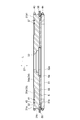
- FIG. 4 is a cross-sectional view of the cooling unit taken along line IV-IV of FIG. 3.
- FIG. 5 is a cross-sectional view of the cooling unit taken along the line VV of FIG. 3.
- It is sectional drawing of a holder and a solid immersion lens. It is sectional drawing which shows the state which the solid immersion lens contacted the semiconductor device. It is sectional drawing which shows the state which the solid immersion lens separated from the semiconductor device.
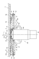
- the semiconductor inspection device 1 shown in FIG. 1 is a device for observing and inspecting a semiconductor device 2 which is a device (DUT: Device Under Test) to be inspected.
- the semiconductor inspection device 1 is used, for example, to identify a failure location in the semiconductor device 2.
- the semiconductor device 2 is a device including, for example, a logic LSI (Large Scale Integration).
- the logic LSI is composed of a MOS (Metal-Oxide-Semiconductor) structure transistor, a bipolar structure transistor, and the like.
- the power consumption of the semiconductor device 2 is, for example, about 200W.
- the semiconductor device 2 is arranged (fixed) on the stage 3.
- the semiconductor inspection device 1 includes a signal input device 11, a light source 12, an optical system 13, a photodetector 14, and a controller 15.
- the signal input device 11 is electrically connected to the semiconductor device 2 and inputs a signal to the semiconductor device 2 to drive the semiconductor device 2.
- the signal input device 11 is, for example, a pulse generator that applies a stimulus signal to the semiconductor device 2 or a tester unit that inputs a test signal to the semiconductor device 2.
- the signal input device 11 repeatedly inputs a signal such as a predetermined test pattern to the semiconductor device 2.
- the signal input by the signal input device 11 may be a modulated voltage signal or a DC voltage signal.
- the light source 12 outputs light that illuminates the semiconductor device 2.
- the light source 12 is, for example, an LED (Light Emitting Diode), an LD (Laser Diode), an SLD (Super Luminescent Diode), or a lamp light source.
- the wavelength of light output from the light source 12 may be, for example, 1064 nm or more.
- the light output from the light source 12 is guided to the optical system 13.
- the optical system 13 guides the light output from the light source 12 to the surface 2 a of the semiconductor device 2 and also guides the light from the surface 2 a of the semiconductor device 2 to the photodetector 14.
- the optical system 13 includes, for example, an objective lens 16, an optical scanner (not shown), and a beam splitter (not shown).
- the objective lens 16 collects the light output from the light source 12 and guided by the beam splitter and the optical scanner in the observation area or scans the light in the observation area.
- the optical system 13 is mounted on, for example, an XYZ stage (not shown).
- the XYZ stage is configured to be movable in the Z-axis direction, and in the X-axis direction and the Y-axis direction orthogonal to the Z-axis direction, where the direction parallel to the optical axis of the objective lens 16 is the Z-axis direction.
- the observation area is determined by the position of the XYZ stage.
- the light emitted from the light source 12 and emitted from the optical system 13 is reflected by the driving semiconductor device 2 and enters the photodetector 14 via the optical system 13. At this time, the intensity of light reflected by the semiconductor device 2 is modulated according to the driving state of the semiconductor device 2.
- the photodetector 14 detects the light modulated by the semiconductor device 2 and outputs waveform data.
- the photodetector 14 may detect light that is incident while the semiconductor device 2 is being scanned with light by the optical scanner, and output a measurement image. Based on these waveform data and the measurement image, the failure location in the semiconductor device 2 can be identified.
- the photodetector 14 may detect the light incident on the semiconductor device 2 while the light is being scanned, and output a pattern image.
- the pattern image is an image captured so that the circuit pattern and the like of the semiconductor device 2 can be confirmed.
- a photodiode capable of detecting light having a wavelength transmitted through the substrate of the semiconductor device 2, an APD (Avalanche Photodiode), a SiPM (Silicon Photomultiplier), or the like can be used.
- the control unit 15 is electrically connected to the signal input device 11, the light source 12, the optical system 13, the photodetector 14, and the like, and controls the entire semiconductor inspection device 1.
- the control unit 15 is configured by, for example, a computer including a processor (CPU: Central Processing Unit), a storage medium such as a RAM (Random Access Memory), a ROM (Read Only Memory), and an HDD (Hard Disk Drive). ..
- the control unit 15 executes processing by the processor on the data stored in the storage medium.
- the control unit 15 performs a process of identifying a failure location in the semiconductor device 2 based on the detection result of the photodetector 14, for example. [Configuration for cooling semiconductor devices]
- the semiconductor inspection device 1 further includes a cooling unit 21, a storage tank 22, four regulators (pressure adjusting units) 23, a drain tank 24, and a chiller 25.
- the cooling unit 21, the storage tank 22, the regulator 23, the drain tank 24, and the chiller 25 are used to cool the semiconductor device 2 during the inspection of the semiconductor device 2.
- the cooling unit 21 is combined with the objective lens 16 to form an objective lens module 60. [Cooling unit]
- the cooling unit 21 will be described with reference to FIGS. 2 to 8.
- the cooling unit 21 is arranged so as to face the semiconductor device 2 and defines a space (gap) S 1 between the cooling unit 21 and the semiconductor device 2.
- the semiconductor device 2 is cooled by flowing the fluid 5 into the space S1.
- the fluid 5 is, for example, water or pure water, but may be a Fluorinert (registered trademark)-based liquid having an electrical insulating property.
- the cooling unit 21 is attached to the stage 3 on which the semiconductor device 2 is arranged.
- the stage 3 includes a DUT board 3a and a holding unit 3b.
- the DUT board 3a is formed in a plate shape, for example, and constitutes a connecting portion between the signal input device 11 and the semiconductor device 2.
- the DUT board 3a may incorporate a socket that constitutes a connecting portion between the signal input device 11 and the semiconductor device 2.
- the semiconductor device 2 has a package 2b and a die 2c protruding from the package 2b.
- the package 2b is a PC board
- the die 2c is a semiconductor portion mounted (bonded) on the package 2b.
- the holding unit 3b is fixed to the DUT board 3a and holds the semiconductor device 2.
- the holding portion 3b is formed of, for example, metal into a plate shape.
- the holding portion 3b is provided with an opening 3c.
- the opening 3c has a first portion R1 in which the package 2b is arranged and a second portion R2 in which the die 2c is arranged, and is opened in each of the first portion R1 and the second portion R2.
- the holding portion 3b has a locking portion 3d that comes into contact with the peripheral edge of the package 2b arranged in the first portion R1.
- the locking portion 3d is formed by the inner surface defining the second portion R2 of the opening 3c being located inside the inner surface defining the first portion R1.
- the thickness of the locking portion 3d is equal to the thickness of the die 2c, but the thickness of the locking portion 3d may be thicker or thinner than the thickness of the die 2c.
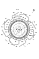
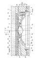
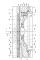
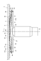
- the cooling unit 21 includes a jacket 31 for radiating the heat of the semiconductor device 2.
- the jacket 31 is made of metal, for example, and is formed in a substantially disk-shaped block shape.
- the jacket 31 is arranged so as to face the semiconductor device 2 and the holding portion 3b.
- the jacket 31 has a first surface 31a and a second surface 31b opposite to the first surface 31a.
- the first surface 31a is a surface that faces the semiconductor device 2 and the holding portion 3b when the cooling unit 21 is attached to the stage 3.
- the jacket 31 is provided with an opening 32 penetrating the jacket 31 along a direction D1 perpendicular to the first surface 31a.
- the opening 32 has, for example, a substantially truncated cone shape that widens toward the second surface 31b side.
- the opening 32 functions as a light passage portion that allows the light from the semiconductor device 2 to pass therethrough.
- a recess 33 is formed on the first surface 31a.
- the concave portion 33 is formed by making the portion of the first surface 31a other than the peripheral edge portion 31a1 lower than the peripheral edge portion 31a1.
- the recess 33 has a first portion 34 and a second portion 35.
- the first portion 34 is an annular portion that surrounds the opening 32 when viewed in the direction D1.
- the second portion 35 is an annular portion that is located outside the first portion 34 and continues to the first portion 34 when viewed in the direction D1.
- the depth of the second portion 35 is deeper than the depth of the first portion 34.
- the bottom surface 34a of the first portion 34 is continuous with the opening 32 and surrounds the opening 32 when viewed from the direction D1.
- the bottom surface 34a extends in a plane and has an annular shape when viewed in the direction D1.
- a groove (recess) 36 extending spirally (spirally) is formed on the bottom surface 34a of the first portion 34 (FIGS. 7 and 8).
- a pair of arrangement grooves 37 in which the elastic members 41 and 42 are arranged are formed on the bottom surface 35a of the second portion 35.
- the elastic members 41 and 42 are members that are sandwiched between the jacket 31 and the holding portion 3b to seal the space S1.
- the elastic members 41 and 42 are formed in, for example, a ring shape.
- the elastic members 41 and 42 are hatched for easy understanding.
- four magnets 38 are arranged in the peripheral portion 31a1 of the first surface 31a at regular intervals in the circumferential direction. By using the attractive force of the magnet 38, the jacket 31 can be detachably attached to the holding portion 3b.
- the jacket 31 is provided with four supply flow paths 51 through which the fluid 5 supplied to the space S1 flows and four discharge flow paths 52 through which the fluid 5 discharged from the space S1 flows.
- Each supply channel 51 extends linearly and is open to the outer surface 31c of the jacket 31 and the inner surface 32a of the opening 32.
- the four supply channels 51 are arranged at regular intervals in the circumferential direction.
- a valve 53 that can be opened and closed is provided at each opening on the outer side surface 31c. As shown in FIG. 3, each valve 53 is connected to a pipe P1 through which the fluid 5 supplied from the storage tank 22 flows.
- the supply channel 51 the fluid 5 flows from the outer surface 31c toward the inner surface 32a, and the fluid 5 is discharged into the opening 32. That is, the supply flow path 51 is configured to discharge the fluid 5 toward the opening 32.
- Each of the discharge flow paths 52 extends linearly and is open to the outer surface 31c of the jacket 31 and the bottom surface 35a of the second portion 35.
- the four discharge flow paths 52 are arranged at regular intervals in the circumferential direction.
- a valve 54 that can be opened and closed is provided at each opening on the outer side surface 31c.
- each valve 54 is connected to a pipe P2 through which the fluid 5 discharged to the drain tank 24 flows.
- the fluid 5 flows from the bottom surface 35 a toward the outer side surface 31 c, and the fluid 5 is discharged to the outside of the jacket 31.
- FIG. 3 shows a discharge port 52a through which the fluid 5 is discharged from the discharge flow channel 52 to the bottom surface 35a.
- the jacket 31 is provided with a coolant passage 55 through which the coolant 6 for cooling the jacket 31 flows.
- the coolant 6 is, for example, water.
- the coolant flow channel 55 extends, for example, in a plane perpendicular to the direction D1, and has a ring shape surrounding the opening 32 when viewed from the direction D1.
- the coolant channel 55 is open to the outside on the outer surface 31c of the jacket 31.
- the coolant channel 55 is open at four locations at regular intervals in the circumferential direction.
- each opening is provided with a valve 56 that can be opened and closed.
- each valve 56 is connected to a pipe P3 through which the refrigerant 6 flows.
- the coolant 6 flows from one or more openings toward the other openings, and the coolant 6 flows in the coolant channel 55. As a result, the jacket 31 is cooled.
- FIGS. 4 and 5 the region in which the refrigerant 6 flows is shown by hatching.
- the fluid 5 is stored in the storage tank 22.
- the fluid 5 in the storage tank 22 is pressurized by a compressor (not shown) and is supplied to the supply flow path 51 via the regulator 23.
- Each of the four regulators 23 is connected to the supply flow path 51 via the pipe P1.
- Each regulator 23 is controlled by the controller 15 and changes the pressure of the fluid flowing through the supply passage 51. As a result, the pressure of the fluid 5 flowing in the space S1 is adjusted.
- the fluid 5 discharged from the discharge flow path 52 is stored in the drain tank 24.
- the chiller 25 cools the coolant 6 and circulates it in the coolant passage 55.
- the fluid 5 is cooled by the jacket 31 while flowing through the supply flow path 51.
- the outer surface 31 c of the jacket 31 is provided with two water leakage sensors 43 and 44.
- the water leak sensor 43 is arranged so as to extend along the boundary between the outer surface 31c and the first surface 31a.
- the water leak sensor 43 detects whether the fluid 5 is leaking between the jacket 31 and the holding portion 3b.
- the water leakage sensor 44 is arranged so as to extend along the boundary between the outer surface 31c and the second surface 31b.
- the water leakage sensor 44 detects whether the fluid 5 or the refrigerant 6 is leaking from the valves 53, 54 and 56, and whether the refrigerant 6 is leaking from a gap formed in the refrigerant flow passage 55 or the like.
- the cooling unit 21 is combined with the objective lens 16 to form an objective lens module 60.
- the objective lens module 60 includes a solid immersion lens unit 61 attached to the objective lens 16 in addition to the cooling unit 21 and the objective lens 16 described above.
- the solid immersion lens unit 61 includes a solid immersion lens 62 and a holder 63.
- the objective lens 16 is arranged so as to face the semiconductor device 2 through the opening 32 of the jacket 31.
- the solid immersion lens 62 is held in the opening 32 by the holder 63 and is located on the optical axis L of the objective lens 16. In this example, the extending direction of the optical axis L is parallel to the direction D1.
- the side on which the objective lens 16 is located with respect to the semiconductor device 2 is the lower side, and the semiconductor device 2 with respect to the objective lens 16.
- the side where is located is the upper side.
- the solid immersion lens 62 has a contact surface 62a, a spherical surface 62b, a tapered surface 62c, and a peripheral surface 62d.
- the contact surface 62a is a flat surface and contacts the die 2c of the semiconductor device 2.
- the spherical surface 62 b is a hemispherical surface convex downward and faces the objective lens 16.
- the tapered surface 62c is a truncated cone-shaped surface that spreads downward, and extends downward from the outer edge of the contact surface 62a.
- the peripheral surface 62d is a cylindrical surface, and is connected to the outer edge of the spherical surface 62b and the outer edge of the tapered surface 62c.
- the apex of the virtual cone including the tapered surface 62c coincides with the spherical center C (center of curvature of the spherical surface 62b) of the solid immersion lens 62, and is located on the optical axis L of the objective lens 16 above the contact surface 62a. ing.
- the ball center C coincides with the focal point of the solid immersion lens 62.
- the solid immersion lens 62 is formed of a high refractive index material that is substantially the same as or close to the refractive index of the substrate material of the semiconductor device 2. Typical examples thereof include Si, GaP, GaAs and the like.
- the solid immersion lens 62 transmits the observation light.
- the semiconductor device 2 itself can be used as a part of the solid immersion lens 62 by bringing the solid immersion lens 62 into optical contact with the semiconductor device 2. According to the back surface analysis of the semiconductor device 2 using the solid immersion lens 62, when the focus of the objective lens 16 is focused on the integrated circuit formed on the substrate surface of the semiconductor device 2, the effect of the solid immersion lens 62 causes the semiconductor A light beam with a high numerical aperture (NA) can be passed through the device 2, and high resolution can be achieved.
- NA numerical aperture
- the solid immersion lens 62 is held by the holder 63 in the opening 32.
- the holder 63 includes a main body 71 and a flexible member 72.
- the main body portion 71 has a side wall portion 73 and a lid portion 74.
- the main body portion 71 is formed of a non-magnetic material (eg, aluminum, aluminum alloy, non-magnetic stainless steel, etc.).
- the side wall portion 73 is formed in a tubular shape.
- the side wall portion 73 is connected to the mechanism portion 16 a provided on the side surface of the objective lens 16.
- the lid portion 74 is formed integrally with the side wall portion 73 so as to close the upper opening of the side wall portion 73.
- the lid 74 has an opening 74a in which the solid immersion lens 62 is placed.
- the opening 74a is arranged on the optical axis L, and opens on the upper side and the lower side.
- the lid portion 74 has a plurality of (for example, three) protrusions 75 extending from the inner surface of the opening 74a toward the center of the opening 74a.
- the protruding portion 75 has a tapered shape, and the surface on the semiconductor device 2 side is an inclined surface that is inclined so as to approach the objective lens 16 as it approaches the center of the opening 74a.
- the plurality of protrusions 75 are arranged, for example, at regular intervals in the circumferential direction.
- the flexible member 72 is made of, for example, resin or the like, and has a shape in which a planar member is bent.
- the flexible member 72 is provided on the opposite side of the lid 74 from the objective lens 16 so as to close the opening 74a of the lid 74.
- the flexible member 72 has an opening 72a in which the solid immersion lens 62 is arranged.
- the opening 72a is arranged on the optical axis L.
- the flexible member 72 has an annular sealing portion 72b that is joined to the peripheral edge portion (in this example, the tapered surface 62c and the peripheral surface 62d) of the solid immersion lens 62 along the edge of the opening 72a.
- the sealing portion 72b watertightly seals between the solid immersion lens 62 and the flexible member 72.
- the flexible member 72 has a joint 72c that is watertightly joined to the lid 74 by, for example, welding or adhesion.
- the contact surface 62a and the tapered surface 62c project upward from the opening 72a of the flexible member 72, and the spherical surface 62b projects downward from the opening 74a of the lid 74. It is arranged in the opening 74a.
- the spherical surface 62b is in contact with the tip of each protruding portion 75, and the contact surface 62a and the tapered surface 62c are held by the flexible member 72.
- the solid immersion lens 62 can swing in the state before the contact surface 62a contacts the semiconductor device 2 (FIG. 8).
- the solid immersion lens 62 swings, the spherical surface 62b slides with respect to the tip of the protruding portion 75, and the flexible member 72 deforms following the swing of the solid immersion lens 62. Since the solid immersion lens 62 is swingable, when the contact surface 62 a is brought into contact with the semiconductor device 2, the solid immersion lens 62 is easily followed and closely adhered to the semiconductor device 2. As a result, for example, even when the semiconductor device 2 is arranged to be inclined with respect to the optical axis L, the solid immersion lens 62 can be brought into good contact with the semiconductor device 2 and the semiconductor device 2 can be observed. It will be possible.
- the objective lens module 60 further includes a sealing member 64 that seals between the holder 63 and the jacket 31.
- the sealing member 64 is formed in a ring shape from an elastic material such as resin.
- the sealing member 64 is disposed in the recess 32b provided on the inner surface 32a of the opening 32 of the jacket 31.
- the sealing member 64 is sandwiched between the side wall portion 73 and the bottom surface of the recess 32b, and seals between the holder 63 and the jacket 31 in a watertight manner.
- the objective lens module 60 further includes four connecting portions 81 that connect the cooling unit 21 and the objective lens 16 to each other.
- Each connecting portion 81 is configured by, for example, a bolt 83 with a spring (biasing member) 82.
- Each connecting portion 81 is arranged in an arrangement hole 84 provided in the first portion 34 of the recess 33 of the jacket 31.
- the arrangement hole 84 communicates the first portion 34 and the opening 32.
- the four connecting portions 81 are arranged along the circumferential direction at regular intervals in the circumferential direction.
- the head of the bolt 83 is arranged in the arrangement hole 84, and the screw portion of the bolt 83 is screwed into the lid portion 74 of the holder 63.
- the spring 82 biases the jacket 31 toward the side opposite to the objective lens 16.
- the urging force pushes the jacket 31 against the holding portion 3b.
- the elastic members 41 and 42 are elastically deformed and come into close contact with the holding portion 3b, and the jacket 31 and the holding portion 3b are sealed.
- the mechanism portion 16a of the objective lens 16 includes a biasing mechanism 16b that biases the holder 63 toward the semiconductor device 2 (FIG. 2).
- the biasing mechanism 16b is used to secure the adhesion of the solid immersion lens 62 to the semiconductor device 2.
- the urging mechanism 16b includes, for example, a guide member extending in the axial direction and a spring held by the guide member. [Space formed by cooling unit]
- the solid immersion lens 62 is separated from the semiconductor device 2 and then the objective lens 16 is moved by the above-mentioned XYZ stage to move the solid immersion lens 62 to the semiconductor device. 2, the solid immersion lens 62 is brought into contact with the semiconductor device 2 as shown in FIG. In the state of FIG. 7, the adhesion force of the solid immersion lens 62 to the semiconductor device 2 is secured (adjusted) by the biasing mechanism 16b. In both states of FIG. 7 and FIG. 8, the cooling unit 21 is attached to the stage 3, and a space S1 is formed between the cooling unit 21 and the semiconductor device 2. That is, since the jacket 31 is urged toward the holding portion 3b by the connecting portion 81, even when the solid immersion lens 62 is separated from the semiconductor device 2 as shown in FIG. Is maintained in close contact with.
- the space S1 is formed between the package 2b and the die 2c of the semiconductor device 2 and the bottom surface 34a of the first portion 34 of the recess 33 provided in the jacket 31. That is, in this example, the bottom surface 34a of the first portion 34 is a space defining surface that faces the semiconductor device 2 and defines the space S1 between the semiconductor device 2 and the semiconductor device 2.
- the depth of the space S1 between the package 2b and the bottom surface 34a is deeper than the depth of the space S1 between the die 2c and the bottom surface 34a.
- the space S1 is continuous with the opening 32 when viewed from the direction D1, and extends in an annular shape so as to surround the opening 32.
- the thickness of the space S1 (the minimum thickness in the direction D1, that is, the distance between the die 2c and the bottom surface 34a in the direction D1) is 0.05 mm or more and 0.5 mm or less. In this example, the thickness of the space S1 is equal to the sum of the depth of the first portion 34 and the thickness of the locking portion 3d of the holding portion 3b.
- the groove 36 described above is arranged so that at least a part thereof is exposed in the space S1.
- a space S2 is formed.
- the depth of the space S2 in the second portion 35 is deeper than the depth of the space S2 in the first portion 34.
- the space S2 is connected to the discharge flow channel 52 at the bottom surface 35a.
- the fluid 5 discharged from the space S1 to the discharge flow path 52 is stored in the space S2 in the second portion 35. That is, the space S2 in the second portion 35 functions as a pool portion that stores the fluid 5 discharged to the discharge flow path 52.
- the space S2 is connected to the space S1 and extends in an annular shape so as to surround the space S1 when viewed from the direction D1.
- the outer edge of the space S2 is sealed by the elastic members 41 and 42 described above.
- the space S3 in the opening 32 is connected to the supply flow path 51.
- the solid immersion lens unit 61 is disposed in the space S3, and the end portion of the space S3 on the objective lens 16 side is sealed by the sealing member 64 described above. More specifically, the ends of the space S3 on the objective lens 16 side are sealed by sealing between the jacket 31 and the holding portion 3b by the elastic members 41 and 42. Further, as described above, the solid immersion lens 62 and the flexible member 72, and the flexible member 72 and the lid portion 74 of the holder 63 are watertightly sealed. As described above, the space (flow path) formed by the spaces S1, S2 and S3 is sealed.
- the fluid 5 supplied from the supply channel 51 to the space S3 flows through the spaces S1 to S3.
- the fluid 5 flows from the space S3 through the space S1 to the space S2 and is discharged from the discharge flow path 52.
- the region where the fluid 5 flows is shown by hatching.
- the position where the fluid 5 is supplied from the supply flow path 51 to the spaces S1 to S3 is the position where the fluid 5 is discharged from the spaces S1 to S3 to the discharge flow path 52 (discharging). It is located inside the position of the outlet 52a).
- the pressure of the fluid 5 flowing through the spaces S1 to S3 is changed by the regulator 23.
- the control unit 15 controls each regulator 23 so that the pressure of the fluid 5 flowing in the spaces S1 to S3 becomes lower than the pressure outside the cooling unit 21 (that is, the pressure in the spaces S1 to S3 becomes negative). Control. This makes it possible to bring the cooling unit 21 into close contact with the stage 3 in a suitable manner.
- the semiconductor device 2 is placed (fixed) on the stage 3 (first step).
- the cooling unit 21 is arranged such that the opening 32 faces the semiconductor device 2 and the space S1 is defined between the jacket 31 and the semiconductor device 2 (second step). More specifically, for example, the objective lens 16 (objective lens module 60) is moved by the XYZ stage described above, and the cooling unit 21 is attached to the stage 3 so that the opening 32 faces the semiconductor device 2. As a result, spaces S1 to S3 are formed between the cooling unit 21 and the stage 3.
- the objective lens 16 is moved by the XYZ stage to move the solid immersion lens 62 toward the semiconductor device 2, and the contact surface 62a of the solid immersion lens 62 is brought into contact with the semiconductor device 2 (see FIG. 3 steps).
- the semiconductor device 2 is driven by the signal input device 11 (fourth step).
- the light that has come from the semiconductor device 2 being driven and has passed through the opening 32 is detected by the photodetector 14 (fifth step).
- the fourth step of driving the semiconductor device 2 may be performed before the second step or the third step.
- the solid immersion lens 62 When changing the observation area, the solid immersion lens 62 is moved away from the semiconductor device 2 by moving the objective lens 16 by the XYZ stage (FIG. 8). At this time, since the jacket 31 is biased toward the holding portion 3b by the connecting portion 81, the cooling unit 21 is kept in close contact with the stage 3. Further, the attractive force of the magnet 38 also urges the jacket 31 toward the holding portion 3b. Then, the objective lens 16 (objective lens module 60) is moved in the X-axis direction and/or the Y-axis direction by the XYZ stage, and the solid immersion lens 62 is moved to a position corresponding to a desired observation area.
- the solid immersion lens 62 is moved toward the semiconductor device 2 by moving the objective lens 16 by the XYZ stage, and the solid immersion lens 62 is brought into contact with the semiconductor device 2. Thereby, the observation area can be changed.
- the cooling unit 21 when the cooling unit 21 is used to inspect the semiconductor device 2, for example, the opening 32 faces the semiconductor device 2 and the space S1 is formed between the bottom surface 34a of the first portion 34 and the semiconductor device 2.
- the cooling unit 21 is arranged as defined. Then, while flowing the fluid 5 into the space S1 through the supply flow path 51, the light emitted from the driving semiconductor device 2 and passing through the opening 32 is detected. By flowing the fluid 5 into the space S1 defined between the jacket 31 and the semiconductor device 2, the semiconductor device 2 can be effectively cooled. This is because the heat of the semiconductor device 2 is removed by the fluid 5 and the heat of the semiconductor device 2 is efficiently transferred to the jacket 31 via the fluid 5.
- the fluid 5 is used for cooling, even if the semiconductor device 2 is warped due to a manufacturing error or heat generation, the fluid 5 is in good contact with the semiconductor device 2. Therefore, even in such a case, the cooling performance can be secured. Therefore, according to this cooling unit 21, high cooling performance can be realized.
- the semiconductor device 2 can be effectively cooled by flowing the fluid 5 into the space S1.
- a boundary layer in which the flow velocity continuously changes is generated at the boundary between the viscous fluid and the object.
- the thicker the boundary layer and the less the change in flow velocity with distance from the body the slower the rate of heat exchange between the fluid and the body.
- the flow velocity increases as the gap becomes narrower.
- the velocity gradient inside the boundary layer is inversely proportional to the size of the gap and increases in proportion to the flow velocity.
- the cooling unit 21 by utilizing this phenomenon, the heat resistance in the heat transfer from the semiconductor device 2 to the fluid 5 and the heat transfer from the fluid 5 to the jacket 31 is significantly suppressed, and the heat of the semiconductor device 2 is efficiently transferred. It becomes possible to communicate well.
- the heat conductive grease may not be used because the heat conductive grease may prevent the solid immersion lens 62 from adhering to the semiconductor device 2.
- a minute gap space S1 is provided between the jacket 31 and the semiconductor device 2, and the fluid 5 is caused to flow in the gap so that the fluid 5 functions as a dynamic grease. You can As a result, the semiconductor device 2 can be effectively cooled.
- the jacket 31 is provided with a discharge flow path 52 through which the fluid 5 discharged from the space S1 flows.
- the fluid can flow into the space S1 via the supply flow path 51 and the discharge flow path 52, and the semiconductor device 2 can be cooled more effectively.
- the jacket 31 is provided with a coolant passage 55 through which the coolant 6 for cooling the jacket 31 flows. Thereby, the jacket 31 can be cooled more appropriately.
- the bottom surface 34a of the first portion 34 is continuous with the opening 32, and extends in a plane shape so as to surround the opening 32. Thereby, the semiconductor device 2 can be cooled more effectively.
- the thickness of the space S1 is 0.05 mm or more and 0.5 mm or less. Thereby, the semiconductor device 2 can be cooled more effectively. That is, when the thickness of the space S1 is 0.05 mm or more and 0.5 mm or less, the heat of the semiconductor device 2 can be effectively removed by the fluid 5. As a result, for example, it becomes possible to cool the semiconductor device 2 of about 200 W at a flow rate of about 0.2 liter/minute.
- the thickness of the space S1 may be greater than 0 mm and 0.05 mm or less. In this case, the fluid 5 flowing in the space S1 easily functions as a heat conduction medium, and the heat of the semiconductor device 2 can be more efficiently transferred to the jacket 31.
- the thickness of the space S1 may be 0.1 mm or more and 0.5 mm or less.
- the space defining surface that defines the space S1 is the bottom surface 34a of the recess 33 formed in the jacket 31. Thereby, the space S1 can be more preferably defined between the jacket 31 and the semiconductor device 2.
- the cooling unit 21 includes elastic members 41 and 42 that are sandwiched between the jacket 31 and the stage 3 to seal the space S1. Thereby, the space S1 between the jacket 31 and the semiconductor device 2 can be sealed more reliably.
- the jacket 31 is provided with four supply channels 51. Thereby, the semiconductor device 2 can be cooled more effectively. That is, by providing at least two supply channels 51, the fluid 5 can be supplied to the periphery of the contact position regardless of the contact position of the solid immersion lens 62 with the semiconductor device 2. Furthermore, since at least two supply channels 51 are provided, it is possible to facilitate control of the pressure of the fluid 5 flowing in the space S1. When at least three supply channels 51 are provided, these functions and effects are remarkably exhibited.
- the position where the fluid 5 is supplied from the supply flow path 51 to the space S1 is located inside the position where the fluid 5 is discharged from the space S1 to the discharge flow path 52. Thereby, the semiconductor device 2 can be cooled more effectively.
- the supply flow path 51 is configured to discharge the fluid 5 toward the opening 32. Thereby, the semiconductor device 2 can be cooled more effectively.
- a groove 36 is formed on the bottom surface 34a.
- the objective lens module 60 includes a spring 82 that biases the cooling unit 21 toward the side opposite to the objective lens 16. Thereby, the cooling unit 21 can be more closely attached to the stage 3.
- the holder 63 has a flexible member 72 that contacts the peripheral portion of the solid immersion lens 62 and holds the solid immersion lens 62 in a watertight and swingable manner. As a result, the solid immersion lens 62 can be swung, and thus the solid immersion lens 62 can be easily adhered following the semiconductor device 2. Further, since the solid immersion lens 62 is kept watertight, it is possible to prevent the fluid 5 from leaking from around the solid immersion lens 62.
- the objective lens module 60 includes a sealing member 64 that is sandwiched between the holder 63 and the jacket 31 to seal between the holder 63 and the jacket 31. As a result, it is possible to prevent the fluid 5 from leaking between the holder 63 and the jacket 31.
- the semiconductor inspection device 1 includes a regulator 23 that changes the pressure of the fluid 5 flowing in the space S1 and a control unit 15 that controls the regulator 23. Thereby, the semiconductor device 2 can be cooled more effectively.
- control unit 15 controls the regulator 23 so that the pressure of the fluid 5 flowing in the space S1 becomes lower than the pressure outside the cooling unit 21. As a result, the pressure in the space S1 becomes negative, so that the cooling unit 21 can be more closely attached to the stage 3. Further, it is possible to prevent the fluid 5 from leaking from the gap or the like in the spaces S1 to S3.
- the cooling unit 21 may be configured as in the modified examples shown in FIGS. 9, 10, and 11. In the modification, the cooling unit 21 is configured separately from the objective lens 16.
- the solid immersion lens unit 61 is not attached to the objective lens 16.
- a light transmission member 85 is arranged in the opening 32 of the jacket 31.
- the light transmitting member 85 is made of, for example, glass and has a plate shape, and transmits the observation light.
- the light transmitting member 85 closes the opening 32 in a watertight manner.
- the light transmitting member 85 is arranged, for example, so as to project from the opening 32 toward the semiconductor device 2 side, and faces the die 2c of the semiconductor device 2 with a predetermined gap.
- the space S1 is formed between the package 2b and the die 2c of the semiconductor device 2 and the bottom surface 34a of the first portion 34 of the recess 33 provided in the jacket 31. Similar to the above embodiment, a space S2 is formed between the bottom surface 34a of the first portion 34 and the holding portion 3b, and between the bottom surface 35a of the second portion 35 and the holding portion 3b. In the modification, since the opening 32 is closed by the light transmitting member 87, the space S1 is not connected to the space inside the opening 32.
- the semiconductor device 2 can be inspected and observed as in the above embodiment. Moreover, high cooling performance can be realized for the reasons described above. Further, since the light transmitting member 85 closes the opening 32 in a watertight manner, it is possible to prevent the fluid 5 from leaking from the opening 32.
- the semiconductor inspection apparatus 1 includes a biasing device 90 that biases the cooling unit 21 toward the stage 3.
- the biasing device 90 has, for example, a spring 91 and is fixed to the XYZ stage, and biases the cooling unit 21 at its peripheral edge portion by the spring 91. Thereby, the cooling unit 21 can be more closely attached to the stage 3.
- the objective lens 16 When inspecting the semiconductor device 2, the objective lens 16 is positioned at the inspection position shown in FIG. When switching the lens of the objective lens 16 when changing the observation area, the objective lens 16 is lowered from the inspection position to the lens switching position shown in FIG. 11B. Then, after being moved in the XY directions to the position corresponding to the desired observation area, it is raised to the inspection position. On the other hand, in the case of changing the observation area, when the lens of the objective lens 16 is not switched, the objective lens 16 is moved in the XY directions to the position corresponding to the desired observation area while being positioned at the inspection position.
- the semiconductor inspection apparatus 1 is configured as an apparatus that observes the semiconductor device 2 from the vertically lower side, but may be configured as an apparatus that observes the semiconductor device 2 from the vertically upper side. .. In this case, the semiconductor device 2 may be mounted on the stage 3.
- the space defining surface that defines the space S1 with the semiconductor device 2 is formed of the bottom surface 34a that is the bottom surface of the recess 33, but the structure of the space defining surface is not limited to this.
- the recess 33 may not be formed on the first surface 31a of the jacket 31, and the space defining surface may be configured by the first surface 31a formed flat.
- the space defining surface may be provided with a protrusion that abuts on the semiconductor device 2 and defines a space between the space defining surface and the semiconductor device 2.
- the height of the protrusion is the thickness of the space S1.
- the protrusion may be provided on the light transmitting member 85.
- the groove portion 36 extending in a spiral shape is formed on the bottom surface 34a of the first portion 34, but at least one of the concave portion and the convex portion may be formed on the bottom surface 34a.
- the bottom surface 34a may be formed with a plurality of annular groove portions arranged side by side in the radial direction. That is, concentric groove portions may be formed on the bottom surface 34a.
- the bottom surface 34a may be formed with a plurality of convex portions for making the fluid 5 flowing in the space S1 turbulent.
- the jacket 31 is cooled by the refrigerant 6 made of water, but it may be cooled by the refrigerant 6 made of air. That is, the jacket 31 may be air-cooled instead of liquid-cooled. In this case, a thermostreamer may be used.
- the jacket 31 may be provided with a sensor for detecting the temperature of the jacket 31. In this case, the cooling operation can be controlled according to the temperature of the jacket 31.
- At least one of the discharge flow channel 52 and the coolant flow channel 55 may not be provided. When the discharge flow path 52 is not provided, the fluid 5 may be discharged from the gap formed between the stage 3 and the jacket 31, for example. Only one of the supply channel 51 and the discharge channel 52 may be provided.
- the pressure of the fluid in the storage tank 22 may be increased by raising the position of the storage tank 22 instead of increasing the pressure by the compressor.
- a flow rate sensor may be provided in at least one of the supply flow path 51 and the discharge flow path 52.
- the fluid 5 stored in the drain tank 24 may be returned to the storage tank 22 for reuse after being cleaned with a filter or the like.
- the semiconductor device 2 is not limited to a device including a logic LSI.
- the semiconductor device 2 may be an individual semiconductor element (discrete), an optoelectronic element, a sensor/actuator, a memory element, a linear IC (Integrated Circuit) or the like, or a mixed device thereof.
- the individual semiconductor elements include diodes, power transistors and the like.
- the semiconductor device 2 may be a package including a semiconductor device, a composite substrate, or the like.
- the semiconductor device 2 may be formed by, for example, incorporating a plurality of elements (capacitors or the like) in a silicon substrate.
- the regulator 23 and the chiller 25 are controlled by the control unit 15 that controls the signal input device 11 and the like in the above embodiment, the control unit that controls the regulator 23 and the chiller 25 controls the signal input device 11 and the like. It may be configured separately from the unit.
- SYMBOLS 1 Semiconductor inspection device, 2... Semiconductor device, 3... Stage, 5... Fluid, 6... Refrigerant, 14... Photodetector, 15... Control part, 16... Objective lens, 21... Cooling unit, 23... Regulator (pressure adjustment) Part), 31... Jacket, 32... Opening (light passage part), 33... Recess, 34a... Bottom surface (space defining surface), 36... Groove part (recess), 41, 42... Elastic member, 51... Supply flow path, 52 ... discharge channel, 55... refrigerant channel, 60... objective lens module, 62... solid immersion lens, 63... holder, 64... sealing member, 72... flexible member, 82... spring (biasing member), 85 ... Light transmitting member, 90... Energizing device, S1... Space.
Landscapes
- Engineering & Computer Science (AREA)
- Environmental & Geological Engineering (AREA)
- Physics & Mathematics (AREA)
- General Physics & Mathematics (AREA)
- General Engineering & Computer Science (AREA)
- Computer Hardware Design (AREA)
- Microelectronics & Electronic Packaging (AREA)
- Toxicology (AREA)
- Health & Medical Sciences (AREA)
- Testing Or Measuring Of Semiconductors Or The Like (AREA)
- Microscoopes, Condenser (AREA)
- Cooling Or The Like Of Semiconductors Or Solid State Devices (AREA)
- Testing Of Individual Semiconductor Devices (AREA)
- Tests Of Electronic Circuits (AREA)
- Investigating Materials By The Use Of Optical Means Adapted For Particular Applications (AREA)
Abstract
冷却ユニットは、半導体デバイスの検査において用いられる。冷却ユニットは、半導体デバイスの熱を放熱するためのジャケットを備える。ジャケットには、半導体デバイスからの光を通過させる光通過部が設けられている。ジャケットは、光通過部が半導体デバイスと向かい合う状態において、半導体デバイスと向かい合って半導体デバイスとの間に空間を画定する空間画定面を有する。ジャケットには、空間に供給される流体が流れる供給流路が設けられている。
Description
本開示の一側面は、冷却ユニット、対物レンズモジュール、半導体検査装置及び半導体検査方法に関する。
半導体デバイスの検査において用いられる冷却ユニットとして、例えば、特許文献1に記載されたものが知られている。特許文献1に記載の冷却ユニットは、駆動中の半導体デバイスを冷却しながら観察するために用いられる。特許文献1に記載の冷却ユニットでは、半導体デバイスに冷却液を噴射することにより、半導体デバイスが冷却される。
例えば消費電力が大きな半導体デバイスを検査する場合等には、上述したような冷却ユニットには高い冷却性能が求められる。そこで、本開示の一側面は、冷却性能が高められた冷却ユニット及び対物レンズモジュール、そのような冷却ユニットを備える半導体検査装置、並びに、半導体デバイスを好適に冷却しつつ検査することができる半導体検査方法を提供することを目的とする。
本開示の一側面に係る冷却ユニットは、半導体デバイスの検査において用いられる冷却ユニットであって、半導体デバイスの熱を放熱するためのジャケットを備え、ジャケットには、半導体デバイスからの光を通過させる光通過部が設けられており、ジャケットは、光通過部が半導体デバイスと向かい合う状態において、半導体デバイスと向かい合って半導体デバイスとの間に空間を画定する空間画定面を有し、ジャケットには、空間に供給される流体が流れる供給流路が設けられている。
この冷却ユニットを半導体デバイスの検査に用いる場合、例えば、光通過部が半導体デバイスと向かい合い、且つ、空間画定面と半導体デバイスとの間に空間が画定されるように、冷却ユニットを配置する。そして、供給流路を介して当該空間に流体を流しながら、駆動中の半導体デバイスから出射されて光通過部を通過した光を検出する。ジャケットと半導体デバイスとの間に画定された空間に流体を流すことにより、半導体デバイスを効果的に冷却することができる。これは、当該流体によって半導体デバイスの熱が取り去られるのに加えて、当該流体を介して半導体デバイスの熱がジャケットに効率良く伝達されるためである。したがって、この冷却ユニットによれば、高い冷却性能を実現することができる。
ジャケットには、空間から排出される流体が流れる排出流路が更に設けられていてもよい。この場合、供給流路及び排出流路を介して空間に流体を流すことができ、半導体デバイスをより効果的に冷却することができる。
ジャケットには、ジャケットを冷却するための冷媒が流れる冷媒流路が更に設けられていてもよい。この場合、ジャケットをより好適に冷却することができる。
空間画定面は、光通過部を囲むように延在していてもよい。この場合、半導体デバイスをより一層効果的に冷却することができる。
空間画定面は、平面状に延在してもよい。この場合、半導体デバイスをより一層効果的に冷却することができる。
空間画定面は、光通過部に連なっていてもよい。この場合、半導体デバイスをより一層効果的に冷却することができる。
空間画定面は、ジャケットに形成された凹部の底面であってもよい。この場合、より好適にジャケットと半導体デバイスとの間に空間を画定することができる。
空間の厚さは、0mmよりも大きく0.05mm以下であってもよい。この場合、半導体デバイスをより一層効果的に冷却することができる。
或いは、空間の厚さは、0.05mm以上0.5mm以下であってもよい。この場合、半導体デバイスをより一層効果的に冷却することができる。
本開示の一側面に係る冷却ユニットは、ジャケットと、半導体デバイスが配置されるステージとの間で挟まれて空間を封止する弾性部材を更に備えてもよい。この場合、ジャケットと半導体デバイスとの間の空間をより確実に封止することができる。
ジャケットには、供給流路が少なくとも2つ設けられていてもよい。この場合、半導体デバイスをより一層効果的に冷却することができる。
空間画定面に垂直な方向から見た場合に、供給流路から空間に流体が供給される位置は、空間から排出流路に流体が排出される位置よりも内側に位置していてもよい。この場合、半導体デバイスをより一層効果的に冷却することができる。
供給流路は、光通過部に向けて流体を排出するように構成されていてもよい。この場合、半導体デバイスをより一層効果的に冷却することができる。
空間画定面には、凹部及び凸部の少なくとも一方が形成されていてもよい。この場合、空間を流れる流体を乱流化させることができ、半導体デバイスの熱をジャケットに一層効率良く伝達することができる。
光通過部は、ジャケットに設けられた開口に光透過部材が配置されることによって構成されていてもよい。この場合でも、高い冷却性能を実現することができる。
光透過部材は、開口を水密に塞いでいてもよい。この場合、開口から流体が漏れるのを防止することができる。
本開示の一側面に係る対物レンズモジュールは、上記冷却ユニットと、光通過部と向かい合う対物レンズと、対物レンズの光軸上に位置するように保持された固浸レンズと、を備え、光通過部は、ジャケットに設けられた開口によって構成されており、固浸レンズは、開口に配置されている。この対物レンズモジュールによれば、上述した理由により、高い冷却性能を実現することができる。
本開示の一側面に係る対物レンズモジュールは、冷却ユニットを対物レンズとは反対側に向けて付勢する付勢部材を更に備えてもよい。この場合、例えば、半導体デバイスが配置されるステージに対して冷却ユニットをより好適に密着させることができる。
本開示の一側面に係る対物レンズモジュールは、対物レンズに取り付けられ、固浸レンズを保持するホルダを更に備え、ホルダは、固浸レンズの周縁部に接触して、固浸レンズを水密に且つ揺動可能に保持する可撓性部材を有していてもよい。この場合、固浸レンズが揺動可能であるので、固浸レンズを半導体デバイスに対して倣って密着させ易い。更に、固浸レンズが水密に保持されているため、固浸レンズの周囲から流体が漏れるのを防止することができる。
本開示の一側面に係る対物レンズモジュールは、対物レンズに取り付けられ、固浸レンズを保持するホルダと、ホルダとジャケットとの間で挟まれてホルダとジャケットとの間を封止する封止部材と、を更に備えてもよい。この場合、ホルダとジャケットとの間から流体が漏れるのを防止することができる。
本開示の一側面に係る半導体検査装置は、上記冷却ユニットと、半導体デバイスが配置されるステージと、光通過部を介して半導体デバイスと向かい合う対物レンズと、半導体デバイスからの光を光通過部及び対物レンズを介して検出する光検出器と、を備える。この半導体検査装置によれば、上述した理由により、高い冷却性能を実現することができる。
本開示の一側面に係る半導体検査装置は、空間を流れる流体の圧力を変化させる圧力調整部と、圧力調整部を制御する制御部と、を更に備えてもよい。この場合、半導体デバイスをより一層効果的に冷却することができる。
制御部は、空間を流れる流体の圧力が冷却ユニットの外部の圧力よりも低くなるように、圧力調整部を制御してもよい。この場合、空間内が負圧となるため、冷却ユニットをステージに対してより好適に密着させることができる。また、空間において隙間等から流体が漏れるのを抑制することができる。
本開示の一側面に係る半導体検査装置は、冷却ユニットをステージに向けて付勢する付勢装置を更に備えてもよい。この場合、冷却ユニットをステージに対してより好適に密着させることができる。
本開示の一側面に係る半導体検査方法は、半導体デバイスをステージに配置するステップと、半導体デバイスからの光を通過させる光通過部が設けられたジャケットを有する冷却ユニットを、光通過部が半導体デバイスと向かい合い、且つ、ジャケットと半導体デバイスとの間に空間が画定されるように配置するステップと、半導体デバイスを駆動させるステップと、空間に流体を流しながら、駆動中の半導体デバイスから到来して光通過部を通過した光を光検出器により検出するステップと、を備える。
この半導体検査方法では、ジャケットと半導体デバイスとの間に画定された空間に流体を流しながら、駆動中の半導体デバイスから到来して光通過部を通過した光を検出する。ジャケットと半導体デバイスとの間に画定された空間に流体を流すことにより、半導体デバイスを効果的に冷却することができる。これは、当該流体によって半導体デバイスの熱が取り去られるのに加えて、当該流体を介して半導体デバイスの熱がジャケットに効率良く伝達されるためである。したがって、この半導体検査方法によれば、半導体デバイスを好適に冷却しつつ検査することができる。
本開示の一側面によれば、冷却性能が高められた冷却ユニット及び対物レンズモジュール、そのような冷却ユニットを備える半導体検査装置、並びに、半導体デバイスを好適に冷却しつつ検査することができる半導体検査方法を提供できる。
以下、本開示の一実施形態について、図面を参照しつつ詳細に説明する。なお、以下の説明において、同一又は相当要素には同一符号を用い、重複する説明を省略する。
[半導体検査装置の構成]
[半導体検査装置の構成]
図1に示される半導体検査装置1は、検査対象のデバイス(DUT:Device Under Test)である半導体デバイス2を観察して検査するための装置である。半導体検査装置1は、例えば、半導体デバイス2における故障箇所を特定するために用いられる。
半導体デバイス2は、例えば、ロジックLSI(Large Scale Integration)を含むデバイスである。ロジックLSIは、MOS(Metal-Oxide-Semiconductor)構造のトランジスタ、バイポーラ構造のトランジスタ等により構成される。半導体デバイス2の消費電力は、例えば200W程度である。半導体デバイス2は、ステージ3に配置(固定)されている。
半導体検査装置1は、信号入力装置11と、光源12と、光学系13と、光検出器14と、制御部15とを備えている。信号入力装置11は、半導体デバイス2に電気的に接続されており、半導体デバイス2に信号を入力して半導体デバイス2を駆動させる。信号入力装置11は、例えば、半導体デバイス2に刺激信号を加えるパルスジェネレータ、又は、半導体デバイス2にテスト信号を入力するテスタユニット等である。信号入力装置11は、半導体デバイス2に所定のテストパターン等の信号を繰り返し入力する。信号入力装置11が入力する信号は、変調電圧信号であってもよいし、直流電圧信号であってもよい。
光源12は、半導体デバイス2を照明する光を出力する。光源12は、例えば、LED(Light Emitting Diode)、LD(LaserDiode)、SLD(Super luminescent Diode)又はランプ光源等である。光源12から出力される光の波長は、例えば1064nm以上であってもよい。光源12から出力された光は、光学系13に導かれる。
光学系13は、光源12から出力された光を半導体デバイス2の表面2aへ導光すると共に、半導体デバイス2の表面2aからの光を光検出器14へ導光する。光学系13は、例えば、対物レンズ16、光スキャナ(図示省略)及びビームスプリッタ(図示省略)を含んで構成されている。対物レンズ16は、光源12から出力されてビームスプリッタ及び光スキャナによって導かれた光を、観察エリアに集光したり観察エリアにて走査したりする。光学系13は、例えばXYZステージ(図示省略)に載置されている。XYZステージは、対物レンズ16の光軸に平行な方向をZ軸方向とすると、Z軸方向、並びに、Z軸方向に直交するX軸方向及びY軸方向に移動可能に構成されている。XYZステージの位置によって観察エリアが決定する。
光源12から出力されて光学系13から出射された光は、駆動中の半導体デバイス2により反射され、光学系13を介して光検出器14に入射する。このとき、半導体デバイス2の駆動状態に伴って、半導体デバイス2により反射される光の強度が変調される。
光検出器14は、半導体デバイス2で変調された光を検出し、波形データを出力する。光検出器14は、光スキャナによって半導体デバイス2に対して光が走査されている間に入射した光を検出し、測定画像を出力してもよい。これらの波形データや測定画像に基づいて、半導体デバイス2における故障箇所を特定することができる。
光検出器14は、半導体デバイス2に対して光が走査されている間に入射した光を検出し、パターン画像を出力してもよい。パターン画像とは、半導体デバイス2の回路パターン等を確認可能となるように撮像された画像である。光検出器14としては、例えば、半導体デバイス2の基板を透過する波長の光を検出可能なフォトダイオード、APD(Avalanche Photodiode)、SiPM(SiliconPhotomultiplier)等を用いることができる。
制御部15は、信号入力装置11、光源12、光学系13及び光検出器14等に電気的に接続されており、半導体検査装置1全体の制御を行う。制御部15は、例えば、プロセッサ(CPU:Central Processing Unit)、並びに記憶媒体であるRAM(Random Access Memory)、ROM(Read Only Memory)及びHDD(Hard Disk Drive)等を含むコンピュータにより構成されている。制御部15は、記憶媒体に記憶されたデータに対し、プロセッサによる処理を実行する。制御部15は、例えば、光検出器14の検出結果に基づいて、半導体デバイス2における故障箇所の特定処理を実施する。
[半導体デバイスの冷却のための構成]
[半導体デバイスの冷却のための構成]
半導体検査装置1は、冷却ユニット21と、貯留タンク22と、4つのレギュレータ(圧力調整部)23と、ドレーンタンク24と、チラー25とを更に備えている。冷却ユニット21、貯留タンク22、レギュレータ23、ドレーンタンク24及びチラー25は、半導体デバイス2の検査中に半導体デバイス2を冷却するために用いられる。冷却ユニット21は、対物レンズ16と組み合わせられて対物レンズモジュール60を構成している。
[冷却ユニット]
[冷却ユニット]
図2~図8を参照しつつ、冷却ユニット21について説明する。冷却ユニット21は、半導体デバイス2と向かい合うように配置され、半導体デバイス2との間に空間(隙間)S1を画定する。半導体検査装置1では、空間S1に流体5を流すことにより、半導体デバイス2が冷却される。流体5は、例えば水又は純水であるが、フロリナート(登録商標)系の電気絶縁性を有する液体であってもよい。
冷却ユニット21は、半導体デバイス2が配置されたステージ3に対して取り付けられている。この例では、ステージ3は、DUTボード3aと、保持部3bとを備えている。DUTボード3aは、例えば、板状に形成され、信号入力装置11と半導体デバイス2との間の接続部を構成している。DUTボード3aには、信号入力装置11と半導体デバイス2との間の接続部を構成するソケットが組み込まれていてもよい。図7及び図8に示されるように、半導体デバイス2は、パッケージ2bと、パッケージ2bから突出したダイ2cとを有している。例えば、パッケージ2bは、PCボードであり、ダイ2cは、パッケージ2b上に実装(接合)された半導体部分である。
保持部3bは、DUTボード3aに固定され、半導体デバイス2を保持している。保持部3bは、例えば、金属により板状に形成されている。この例では、保持部3bには開口3cが設けられている。開口3cは、パッケージ2bが配置される第1部分R1、及びダイ2cが配置される第2部分R2を有しており、第1部分R1及び第2部分R2の各々において開口している。保持部3bは、第1部分R1に配置されたパッケージ2bの周縁部に接触する係止部3dを有している。この例では、係止部3dは、開口3cにおける第2部分R2を画定する内面が第1部分R1を画定する内面よりも内側に位置していることにより、形成されている。この例では係止部3dの厚さはダイ2cの厚さと等しいが、係止部3dの厚さはダイ2cの厚さよりも厚くてもよいし、或いは薄くてもよい。
冷却ユニット21は、半導体デバイス2の熱を放熱するためのジャケット31を備えている。ジャケット31は、例えば、金属により、略円板状のブロック状に形成されている。ジャケット31は、半導体デバイス2及び保持部3bと向かい合うように配置されている。
ジャケット31は、第1表面31aと、第1表面31aとは反対側の第2表面31bとを有している。第1表面31aは、冷却ユニット21がステージ3に取り付けられた状態において半導体デバイス2及び保持部3bと向かい合う表面である。ジャケット31には、第1表面31aに垂直な方向D1に沿ってジャケット31を貫通する開口32が設けられている。開口32は、例えば、第2表面31b側に向かって広がる略円錐台形状を呈している。開口32は、半導体デバイス2からの光を通過させる光通過部として機能する。
第1表面31aには、凹部33が形成されている。この例では、凹部33は、第1表面31aの周縁部31a1以外の部分が周縁部31a1よりも低くなっていることにより形成されている。凹部33は、第1部分34と、第2部分35とを有している。第1部分34は、方向D1から見た場合に開口32を囲む円環状の部分である。第2部分35は、方向D1から見た場合に第1部分34の外側に位置して第1部分34に連なる円環状の部分である。第2部分35の深さは、第1部分34の深さよりも深い。第1部分34の底面34aは、開口32に連なっており、方向D1から見た場合に開口32を囲んでいる。底面34aは、平面状に延在し、方向D1から見た場合に円環状を呈している。
第1部分34の底面34aには、渦巻き状(螺旋状)に延在する溝部(凹部)36が形成されている(図7及び図8)。第2部分35の底面35aには、弾性部材41,42がそれぞれ配置される一対の配置溝37が形成されている。弾性部材41,42は、ジャケット31と保持部3bとの間で挟まれて空間S1を封止するための部材である。図3に示されるように、弾性部材41,42は、例えば、リング状に形成されている。図3では、理解を容易にするために、弾性部材41,42がハッチングで示されている。図3に示されるように、第1表面31aの周縁部31a1には、周方向に一定の間隔を空けて4つの磁石38が配置されている。磁石38の引力を利用することで、ジャケット31を保持部3bに対して取り外し可能に取り付けることができる。
ジャケット31には、空間S1に供給される流体5が流れる4つの供給流路51と、空間S1から排出される流体5が流れる4つの排出流路52と、が設けられている。各供給流路51は、直線状に延在し、ジャケット31の外側面31cと開口32の内面32aとに開口している。4つの供給流路51は、周方向に一定の間隔を空けて配置されている。外側面31cにおける各開口には、開閉可能なバルブ53が設けられている。図3に示されるように、各バルブ53は、貯留タンク22から供給される流体5が流れる配管P1に接続されている。供給流路51においては、外側面31cから内面32aに向かって流体5が流れ、開口32内に流体5が排出される。すなわち、供給流路51は、開口32に向けて流体5を排出するように構成されている。
各排出流路52は、直線状に延在し、ジャケット31の外側面31cと第2部分35の底面35aとに開口している。4つの排出流路52は、周方向に一定の間隔を空けて配置されている。外側面31cにおける各開口には、開閉可能なバルブ54が設けられている。図3に示されるように、各バルブ54は、ドレーンタンク24に排出される流体5が流れる配管P2に接続されている。排出流路52においては、底面35aから外側面31cに向かって流体5が流れ、ジャケット31の外部に流体5が排出される。図3には、排出流路52から底面35aに流体5が排出される排出口52aが示されている。
更に、ジャケット31には、ジャケット31を冷却するための冷媒6が流れる冷媒流路55が設けられている。冷媒6は、例えば水である。冷媒流路55は、例えば、方向D1に垂直に平面状に延在しており、方向D1から見た場合に開口32を囲む円環状を呈している。冷媒流路55は、ジャケット31の外側面31cにおいて外部に開口している。この例では、冷媒流路55は、周方向に一定の間隔を空けて4箇所において開口している。図5に示されるように、各開口には、開閉可能なバルブ56が設けられている。図3に示されるように、各バルブ56は、冷媒6が流れる配管P3に接続されている。冷媒流路55においては、一又は複数の開口から他の開口に向かって冷媒6が流れ、冷媒流路55内を冷媒6が流動する。これにより、ジャケット31が冷却される。図4及び図5では、冷媒6が流動する領域がハッチングで示されている。
再び図1を参照して、流体5及び冷媒6が流れる経路を説明する。流体5は、貯留タンク22に貯留されている。貯留タンク22内の流体5は、コンプレッサ(図示省略)により昇圧され、レギュレータ23を介して供給流路51に供給される。4つのレギュレータ23は、それぞれ、配管P1を介して供給流路51に接続されている。各レギュレータ23は、制御部15により制御され、供給流路51を流れる流体の圧力を変化させる。これにより、空間S1を流れる流体5の圧力が調整される。ドレーンタンク24には、排出流路52から排出された流体5が貯留される。チラー25は、冷媒6を冷却させて冷媒流路55内を循環させる。流体5は、供給流路51を流れる間にジャケット31によって冷却される。
図2等に示されるように、ジャケット31の外側面31cには、2つの漏水センサ43,44が設けられている。漏水センサ43は、外側面31cにおける第1表面31aとの境界に沿って延在するように配置されている。漏水センサ43は、ジャケット31と保持部3bとの間から流体5が漏れていないかどうかを検出する。漏水センサ44は、外側面31cにおける第2表面31bとの境界に沿って延在するように配置されている。漏水センサ44は、バルブ53,54,56から流体5又は冷媒6が漏れていないかどうか、及び、冷媒流路55に形成された隙間等から冷媒6が漏れていないかどうかを検出する。
[対物レンズモジュール]
[対物レンズモジュール]
図2~図8に示されるように、冷却ユニット21は、対物レンズ16と組み合わせられて対物レンズモジュール60を構成している。対物レンズモジュール60は、上述した冷却ユニット21及び対物レンズ16に加えて、対物レンズ16に取り付けられた固浸レンズユニット61を備えている。固浸レンズユニット61は、固浸レンズ62と、ホルダ63とを備えている。対物レンズ16は、ジャケット31の開口32を介して半導体デバイス2と向かい合うように配置されている。固浸レンズ62は、ホルダ63によって開口32内において保持され、対物レンズ16の光軸L上に位置している。この例では、光軸Lの延在方向は方向D1と平行である。
以下の説明では、ステージ3に配置された半導体デバイス2と対物レンズ16が向かい合う状態において、半導体デバイス2に対して対物レンズ16が位置する側を下側とし、対物レンズ16に対して半導体デバイス2が位置する側を上側とする。
図6に示されるように、固浸レンズ62は、当接面62aと、球面62bと、テーパ面62cと、周面62dと、を有している。当接面62aは、平坦面であり、半導体デバイス2のダイ2cに当接する。球面62bは、下側に向かって凸の半球形状の面であり、対物レンズ16と向かい合う。テーパ面62cは、下側に向かって広がる円錐台形状の面であり、当接面62aの外縁から下側に延びている。周面62dは、円柱形状の面であり、球面62bの外縁とテーパ面62cの外縁とに接続されている。テーパ面62cを含む仮想円錐の頂点は、固浸レンズ62の球心C(球面62bの曲率中心)に一致しており、当接面62aの上側において対物レンズ16の光軸L上に位置している。球心Cは、固浸レンズ62の焦点に一致する。
固浸レンズ62は、半導体デバイス2の基板材料と実質的に同一又はその屈折率に近い、高屈折率材料により形成されている。その代表的な例としては、Si、GaP、GaAs等が挙げられる。固浸レンズ62は、観察光を透過させる。固浸レンズ62を半導体デバイス2に光学密着させることにより、半導体デバイス2自身を固浸レンズ62の一部として利用することができる。固浸レンズ62を利用した半導体デバイス2の裏面解析によれば、対物レンズ16の焦点を半導体デバイス2の基板表面に形成された集積回路に合わせた際に、固浸レンズ62の効果により、半導体デバイス2中に開口数(NA)の高い光束を通すことができ、高分解能化が可能となる。
固浸レンズ62は、開口32内においてホルダ63により保持されている。ホルダ63は、本体部71と、可撓性部材72とを備えている。本体部71は、側壁部73と、蓋部74とを有している。本体部71は、非磁性材料(例えば、アルミニウム、アルミニウム合金、非磁性のステンレス鋼等)により形成されている。側壁部73は、筒形状に形成されている。側壁部73は、対物レンズ16の側面に設けられた機構部16aに連結されている。蓋部74は、側壁部73の上側の開口を塞ぐように、側壁部73と一体的に形成されている。
蓋部74には、固浸レンズ62が配置される開口74aが形成されている。開口74aは、光軸L上に配置され、上側及び下側に開口している。蓋部74は、開口74aの内面から開口74aの中心側に向かって延びる複数(例えば、3つ)の突出部75を有している。突出部75は、先細り形状を呈しており、半導体デバイス2側の面が、開口74aの中心に近づくにつれて対物レンズ16に近づくように傾斜した傾斜面となっている。複数の突出部75は、例えば、周方向に一定の間隔を空けて配置されている。
可撓性部材72は、例えば、樹脂等により形成され、面状の部材が折り曲げられたような形状を呈している。可撓性部材72は、蓋部74の開口74aを塞ぐように、蓋部74に対して対物レンズ16とは反対側に設けられている。可撓性部材72には、固浸レンズ62が配置される開口72aが形成されている。開口72aは、光軸L上に配置されている。可撓性部材72は、開口72aの縁に沿って固浸レンズ62の周縁部(この例では、テーパ面62c及び周面62d)に結合された環状の封止部72bを有している。封止部72bにより、固浸レンズ62と可撓性部材72との間が水密に封止されている。可撓性部材72は、例えば、溶着又は接着により蓋部74に水密に結合された結合部72cを有している。
固浸レンズ62は、当接面62a及びテーパ面62cが可撓性部材72の開口72aから上側に突出し、且つ球面62bが蓋部74の開口74aから下側に突出するように、開口72a及び開口74aに配置されている。球面62bは、各突出部75の先端部に接触しており、当接面62a及びテーパ面62cは、可撓性部材72によって保持されている。これにより、固浸レンズ62は、当接面62aが半導体デバイス2に当接する前の状態(図8)において、揺動可能となっている。例えば、固浸レンズ62が揺動すると、球面62bが突出部75の先端部に対して滑ると共に、可撓性部材72が固浸レンズ62の揺動に追従して変形する。固浸レンズ62が揺動可能となっていることで、当接面62aを半導体デバイス2に当接させる際に、固浸レンズ62を半導体デバイス2に対して倣って密着させ易い。その結果、例えば、半導体デバイス2が光軸Lに対して傾斜して配置されている場合でも、固浸レンズ62を半導体デバイス2に良好に密着させることができ、半導体デバイス2を観察することが可能となる。
対物レンズモジュール60は、ホルダ63とジャケット31との間を封止する封止部材64を更に備えている。封止部材64は、例えば、樹脂等の弾性材料によりリング状に形成されている。封止部材64は、ジャケット31の開口32の内面32aに設けられた凹部32bに配置されている。封止部材64は、側壁部73と凹部32bの底面との間で挟まれ、ホルダ63とジャケット31との間を水密に封止している。
対物レンズモジュール60は、冷却ユニット21と対物レンズ16とを互いに連結する4つの連結部81を更に備えている。各連結部81は、例えば、バネ(付勢部材)82付きのボルト83により構成されている。各連結部81は、ジャケット31における凹部33の第1部分34に設けられた配置孔84に配置されている。配置孔84は、第1部分34と開口32とを連通している。4つの連結部81は、周方向に一定の間隔を空けて、周方向に沿って配置されている。各連結部81においては、ボルト83の頭部が配置孔84に配置され、ボルト83のネジ部がホルダ63の蓋部74に螺合されている。バネ82は、ジャケット31を対物レンズ16とは反対側に向けて付勢する。冷却ユニット21がステージ3に取り付けられた状態においては、この付勢力により、ジャケット31が保持部3bに押し付けられる。その結果、弾性部材41,42が弾性変形して保持部3bに密着し、ジャケット31と保持部3bとの間が封止される。
対物レンズ16の機構部16aは、ホルダ63を半導体デバイス2に向けて付勢する付勢機構16bを備えている(図2)。付勢機構16bは、固浸レンズ62の半導体デバイス2に対する密着力を確保するために用いられる。付勢機構16bは、例えば、軸方向に延在するガイド部材と、ガイド部材により保持されたバネとにより構成されている。
[冷却ユニットにより形成される空間]
[冷却ユニットにより形成される空間]
半導体デバイス2の検査時には、例えば、図8に示されるように固浸レンズ62が半導体デバイス2から離間した状態から、上述したXYZステージによって対物レンズ16を移動させることで固浸レンズ62が半導体デバイス2に近づけられ、図7に示されるように固浸レンズ62が半導体デバイス2に接触した状態に移行する。図7の状態においては、付勢機構16bによって固浸レンズ62の半導体デバイス2に対する密着力が確保(調整)されている。図7及び図8のいずれの状態においても、冷却ユニット21はステージ3に取り付けられており、冷却ユニット21と半導体デバイス2との間には空間S1が形成されている。すなわち、連結部81によってジャケット31が保持部3bに向けて付勢されているため、図8に示されるように固浸レンズ62が半導体デバイス2から離間した状態においても、冷却ユニット21がステージ3に密着した状態が維持される。
空間S1は、半導体デバイス2のパッケージ2b及びダイ2cと、ジャケット31に設けられた凹部33の第1部分34の底面34aとの間に形成される。すなわち、この例では、第1部分34の底面34aが、半導体デバイス2と向かい合って半導体デバイス2との間に空間S1を画定する空間画定面となっている。パッケージ2bと底面34aとの間における空間S1の深さは、ダイ2cと底面34aとの間における空間S1の深さよりも深い。空間S1は、方向D1から見た場合に開口32に連なっており、開口32を囲むように円環状に延在している。空間S1の厚さ(方向D1における最小厚さ、すなわち、方向D1におけるダイ2cと底面34aとの間の距離)は、0.05mm以上0.5mm以下である。この例では、空間S1の厚さは、第1部分34の深さと保持部3bの係止部3dの厚さとの和に等しい。上述した溝部36は、その少なくとも一部が空間S1に露出するように配置されている。
また、固浸レンズ62が半導体デバイス2に接触した状態においては、第1部分34の底面34aと保持部3bとの間、及び、第2部分35の底面35aと保持部3bとの間に、空間S2が形成される。第2部分35における空間S2の深さは、第1部分34における空間S2の深さよりも深い。空間S2は、底面35aにおいて排出流路52に接続されている。第2部分35における空間S2には、空間S1から排出流路52に排出される流体5が貯留される。つまり、第2部分35における空間S2は、排出流路52に排出される流体5を貯留するプール部として機能する。空間S2は、空間S1に接続されており、方向D1から見た場合に空間S1を囲むように円環状に延在している。空間S2の外縁は、上述した弾性部材41,42によって封止されている。
開口32内の空間S3は、供給流路51に接続されている。空間S3には固浸レンズユニット61が配置されており、空間S3における対物レンズ16側の端部は、上述した封止部材64によって封止されている。より具体的には、弾性部材41,42によってジャケット31と保持部3bとの間が封止されることで、空間S3における対物レンズ16側の端部が封止されている。また、上述したとおり、固浸レンズ62と可撓性部材72との間、及び、可撓性部材72とホルダ63の蓋部74との間が水密に封止されている。以上により、空間S1,S2及びS3により構成される空間(流路)が封止されている。
供給流路51から空間S3に供給された流体5は、空間S1~S3を流動する。流体5は、空間S3から空間S1を経て空間S2へ流れ、排出流路52から排出される。図3、図7及び図8では、流体5が流動する領域がハッチングで示されている。この例では、方向D1から見た場合に、供給流路51から空間S1~S3に流体5が供給される位置は、空間S1~S3から排出流路52に流体5が排出される位置(排出口52aの位置)よりも内側に位置している。空間S1~S3を流れる流体5の圧力は、レギュレータ23により変化させられる。制御部15は、空間S1~S3を流れる流体5の圧力が冷却ユニット21の外部の圧力よりも低くなるように(すなわち、空間S1~S3内が負圧となるように)、各レギュレータ23を制御する。これにより、冷却ユニット21をステージ3に対して好適に密着させることが可能となる。
[半導体検査方法]
[半導体検査方法]
半導体検査装置1を用いた半導体検査方法では、まず、半導体デバイス2をステージ3に配置(固定)する(第1ステップ)。続いて、冷却ユニット21を、開口32が半導体デバイス2と向かい合い、且つ、ジャケット31と半導体デバイス2との間に空間S1が画定されるように配置する(第2ステップ)。より具体的には、例えば、上述したXYZステージによって対物レンズ16(対物レンズモジュール60)を移動させ、開口32が半導体デバイス2と向かい合うように冷却ユニット21をステージ3に取り付ける。これにより、冷却ユニット21とステージ3との間に空間S1~S3が形成される。
続いて、XYZステージによって対物レンズ16を移動させることで固浸レンズ62を半導体デバイス2に向かって移動させ、固浸レンズ62の当接面62aを半導体デバイス2に当接させる(図7、第3ステップ)。続いて、信号入力装置11によって半導体デバイス2を駆動させる(第4ステップ)。続いて、空間S1~S3に流体5を流しながら、駆動中の半導体デバイス2から到来して開口32を通過した光を光検出器14により検出する(第5ステップ)。以上の工程により、上述したとおり、半導体デバイス2の検査を行うことができる。なお、半導体デバイス2を駆動させる第4ステップは、第2ステップ又は第3ステップよりも前に行われてもよい。
観察エリアを変更する際には、XYZステージによって対物レンズ16を移動させることで固浸レンズ62を半導体デバイス2から遠ざける(図8)。このとき、連結部81によってジャケット31が保持部3bに向けて付勢されているため、冷却ユニット21がステージ3に密着した状態が維持される。また、磁石38の引力によっても、ジャケット31が保持部3bに向けて付勢される。続いて、XYZステージによって対物レンズ16(対物レンズモジュール60)をX軸方向及び/又はY軸方向に移動させ、固浸レンズ62を所望の観察エリアに対応する位置まで移動させる。続いて、XYZステージによって対物レンズ16を移動させることで固浸レンズ62を半導体デバイス2に向かって移動させ、固浸レンズ62を半導体デバイス2に当接させる。これにより、観察エリアを変更することができる。
[作用及び効果]
[作用及び効果]
以上説明したように、冷却ユニット21を半導体デバイス2の検査に用いる場合、例えば、開口32が半導体デバイス2と向かい合い、且つ、第1部分34の底面34aと半導体デバイス2との間に空間S1が画定されるように、冷却ユニット21を配置する。そして、供給流路51を介して当該空間S1に流体5を流しながら、駆動中の半導体デバイス2から出射されて開口32を通過した光を検出する。ジャケット31と半導体デバイス2との間に画定された空間S1に流体5を流すことにより、半導体デバイス2を効果的に冷却することができる。これは、当該流体5によって半導体デバイス2の熱が取り去られるのに加えて、当該流体5を介して半導体デバイス2の熱がジャケット31に効率良く伝達されるためである。更に、流体5を用いて冷却を行うため、仮に半導体デバイス2が製造誤差又は発熱により反っている場合でも、流体5が半導体デバイス2に良好に接触する。したがって、そのような場合でも冷却性能を確保することができる。よって、この冷却ユニット21によれば、高い冷却性能を実現することができる。
空間S1に流体5を流すことにより半導体デバイス2の効果的な冷却が可能となる理由について更に説明する。流体が物体の表面を流れる場合、粘性を有する流体と物体との境界には流速が連続的に変化する境界層が発生する。通常、この境界層の厚さが厚く、且つ物体からの距離に対する流速の変化が少ないほど、流体と物体との間の熱交換の速度は遅くなる。当該境界層を薄くするためには、流速を増加させることが一般的である。ところが、微小な隙間に流体を流す場合、流量を一定とすると、隙間が狭いほど流速が増加する。更に、境界層内部の速度傾斜が隙間の大きさに反比例し、流速に比例して大きくなる。そのため、物体と流体との間の熱抵抗を大幅に抑制することが可能となる。冷却ユニット21では、この現象を利用することで、半導体デバイス2から流体5への熱伝達、及び流体5からジャケット31への熱伝達における熱抵抗を大幅に抑制し、半導体デバイス2の熱を効率良く伝達することが可能となる。
他の冷却方法として、冷却ブロックを熱伝導グリースを介して半導体デバイス2に密着させて半導体デバイス2を冷却する方法が考えられる。しかし、そのような半導体検査装置1においては、熱伝導グリースによって固浸レンズ62の半導体デバイス2に対する密着が妨げられるおそれがあるため、熱伝導グリースを使用することができない。これに対し、冷却ユニット21では、ジャケット31と半導体デバイス2との間に微小な隙間(空間S1)を設け、当該隙間に流体5を流すことで、流体5を動的なグリースとして機能させることができる。その結果、半導体デバイス2を効果的に冷却することが可能となる。
ジャケット31には、空間S1から排出される流体5が流れる排出流路52が設けられている。これにより、供給流路51及び排出流路52を介して空間S1に流体を流すことができ、半導体デバイス2をより効果的に冷却することができる。
ジャケット31には、ジャケット31を冷却するための冷媒6が流れる冷媒流路55が設けられている。これにより、ジャケット31をより好適に冷却することができる。
第1部分34の底面34aが、開口32に連なっており、開口32を囲むように平面状に延在している。これにより、半導体デバイス2をより一層効果的に冷却することができる。
空間S1の厚さが、0.05mm以上0.5mm以下である。これにより、半導体デバイス2をより一層効果的に冷却することができる。すなわち、空間S1の厚さが0.05mm以上0.5mm以下であると、流体5によって半導体デバイス2の熱を効果的に取り去ることができる。その結果、例えば、0.2リットル/分程度の流量で200W程度の半導体デバイス2を冷却することが可能となる。空間S1の厚さは、0mmよりも大きく0.05mm以下であってもよい。この場合、空間S1を流れる流体5が熱伝導媒体として機能し易く、半導体デバイス2の熱をジャケット31に一層効率良く伝達することができる。空間S1の厚さは、0.1mm以上0.5mm以下であってもよい。
空間S1を画定する空間画定面が、ジャケット31に形成された凹部33の底面34aである。これにより、より好適にジャケット31と半導体デバイス2との間に空間S1を画定することができる。
冷却ユニット21は、ジャケット31とステージ3との間で挟まれて空間S1を封止する弾性部材41,42を備えている。これにより、ジャケット31と半導体デバイス2との間の空間S1をより確実に封止することができる。
ジャケット31には、供給流路51が4つ設けられている。これにより、半導体デバイス2をより一層効果的に冷却することができる。すなわち、供給流路51を少なくとも2つ設けることで、半導体デバイス2に対する固浸レンズ62の接触位置にかかわらず、当該接触位置の周辺に流体5を供給することが可能となる。更に、少なくとも2つの供給流路51が設けられていることにより、空間S1を流れる流体5の圧力の制御を容易化することができる。供給流路51が少なくとも3つ設けられている場合、これらの作用効果が顕著に奏される。
方向D1から見た場合に、供給流路51から空間S1に流体5が供給される位置が、空間S1から排出流路52に流体5が排出される位置よりも内側に位置している。これにより、半導体デバイス2を一層効果的に冷却することができる。供給流路51が、開口32に向けて流体5を排出するように構成されている。これにより、半導体デバイス2をより一層効果的に冷却することができる。
底面34aには、溝部36が形成されている。これにより、空間S1を流れる流体5を乱流化させることができ、半導体デバイス2の熱をジャケット31に一層効率良く伝達することができる。これは、乱流化により、境界層の厚さを薄くすることができると共に、空間S1を流れる流体5の温度を均一化することができるためである。
対物レンズモジュール60は、冷却ユニット21を対物レンズ16とは反対側に向けて付勢するバネ82を備えている。これにより、ステージ3に対して冷却ユニット21をより好適に密着させることができる。
ホルダ63が、固浸レンズ62の周縁部に接触して、固浸レンズ62を水密に且つ揺動可能に保持する可撓性部材72を有している。これにより、固浸レンズ62が揺動可能であるので、固浸レンズ62を半導体デバイス2に対して倣って密着させ易い。更に、固浸レンズ62が水密に保持されているため、固浸レンズ62の周囲から流体5が漏れるのを防止することができる。
対物レンズモジュール60は、ホルダ63とジャケット31との間で挟まれてホルダ63とジャケット31との間を封止する封止部材64を備えている。これにより、ホルダ63とジャケット31との間から流体5が漏れるのを防止することができる。
半導体検査装置1は、空間S1を流れる流体5の圧力を変化させるレギュレータ23と、レギュレータ23を制御する制御部15とを備えている。これにより、半導体デバイス2をより一層効果的に冷却することができる。
半導体検査装置1では、制御部15が、空間S1を流れる流体5の圧力が冷却ユニット21の外部の圧力よりも低くなるように、レギュレータ23を制御する。これにより、空間S1内が負圧となるため、冷却ユニット21をステージ3に対してより好適に密着させることができる。また、空間S1~S3において隙間等から流体5が漏れるのを抑制することができる。
[変形例]
[変形例]
冷却ユニット21は、図9、図10及び図11に示される変形例のように構成されてもよい。変形例では、冷却ユニット21は、対物レンズ16とは別体に構成されている。対物レンズ16には、固浸レンズユニット61が取り付けられていない。ジャケット31の開口32には、光透過部材85が配置されている。光透過部材85は、例えばガラスにより板状に形成され、観察光を透過させる。光透過部材85は、開口32を水密に塞いでいる。光透過部材85は、例えば、開口32から半導体デバイス2側に突出するように配置され、所定の間隔を空けて半導体デバイス2のダイ2cと向かい合っている。変形例では、半導体デバイス2のパッケージ2b及びダイ2cと、ジャケット31に設けられた凹部33の第1部分34の底面34aとの間に空間S1が形成される。上記実施形態と同様に、第1部分34の底面34aと保持部3bとの間、及び、第2部分35の底面35aと保持部3bとの間に、空間S2が形成される。変形例では、光透過部材87によって開口32が塞がれているため、空間S1は開口32内の空間とは接続されない。
このような変形例によっても、上記実施形態と同様に、半導体デバイス2の検査及び観察を行うことができる。また、上述した理由により、高い冷却性能を実現することができる。更に、光透過部材85が開口32を水密に塞いでいるため、開口32から流体5が漏れるのを防止することができる。
図11に示されるように、変形例に係る半導体検査装置1は、冷却ユニット21をステージ3に向けて付勢する付勢装置90を備えている。付勢装置90は、例えばバネ91を有してXYZステージに固定されており、バネ91によって冷却ユニット21をその周縁部において付勢している。これにより、冷却ユニット21をステージ3に対してより好適に密着させることができる。
半導体デバイス2の検査時には、対物レンズ16は、図11(a)に示される検査位置に位置付けられる。観察エリアを変更する場合において、対物レンズ16のレンズを切り替えるときには、対物レンズ16は、検査位置から図11(b)に示されるレンズ切替位置まで下降させられる。そして、所望の観察エリアに対応する位置までXY方向に移動させられた後で、検査位置まで上昇させられる。一方、観察エリアを変更する場合において、対物レンズ16のレンズを切り替えないときには、対物レンズ16は、検査位置に位置付けられたままで、所望の観察エリアに対応する位置までXY方向に移動させられる。
各構成の材料及び形状には、上述した材料及び形状に限らず、様々な材料及び形状を採用することができる。上記実施形態では、半導体検査装置1は、半導体デバイス2に対して鉛直下側から観察を行う装置として構成されたが、半導体デバイス2に対して鉛直上側から観察を行う装置として構成されてもよい。この場合、半導体デバイス2は、ステージ3上に載置されてもよい。
上記実施形態では、半導体デバイス2との間に空間S1を画定する空間画定面が、凹部33の底面である底面34aにより構成されたが、空間画定面の構成はこれに限られない。例えば、ジャケット31の第1表面31aに凹部33が形成されず、平坦に形成された第1表面31aにより空間画定面が構成されてもよい。空間画定面には、半導体デバイス2に当接して空間画定面と半導体デバイス2との間の間隔を規定する突出部が設けられていてもよい。この場合、当該突出部の高さが空間S1の厚さとなる。変形例のように光透過部材85が設けられる場合、当該突出部は光透過部材85に設けられてもよい。
上記実施形態では第1部分34の底面34aには渦巻き状に延在する溝部36が形成されていたが、底面34aには凹部及び凸部の少なくとも一方が形成されていればよい。例えば、底面34aには、径方向に並んで配置された円環状の複数の溝部が形成されていてもよい。すなわち、底面34aには、同心円状の溝部が形成されていてもよい。或いは、底面34aには、空間S1を流れる流体5を乱流化させるための複数の凸部が形成されていてもよい。
上記実施形態では、ジャケット31が、水からなる冷媒6により冷却されたが、空気からなる冷媒6により冷却されてもよい。すなわち、ジャケット31は液冷ではなく空冷されてもよい。この場合、サーモストリーマが用いられてもよい。ジャケット31には、ジャケット31の温度を検出するためのセンサが設けられていてもよい。この場合、ジャケット31の温度に応じて冷却動作を制御することが可能となる。排出流路52及び冷媒流路55の少なくとも一方が設けられていなくてもよい。排出流路52が設けられない場合、流体5は、例えば、ステージ3とジャケット31との間に形成された隙間から排出されてもよい。供給流路51及び排出流路52の少なくとも一方は、1つだけ設けられていてもよい。
貯留タンク22内の流体の圧力は、コンプレッサによる昇圧に代えて、貯留タンク22の位置を高くすることにより高められてもよい。供給流路51及び排出流路52の少なくとも一方には、流量センサが設けられてもよい。ドレーンタンク24に貯留されている流体5は、フィルタ等により汚れを取り除いた後に貯留タンク22に戻されて再利用されてもよい。
半導体デバイス2は、ロジックLSIを含むデバイスに限定されない。半導体デバイス2は、個別半導体素子(ディスクリート)、オプトエレクトロニクス素子、センサ/アクチュエータ、メモリ素子、若しくはリニアIC(Integrated Circuit)等、又はそれらの混成デバイス等であってもよい。個別半導体素子は、ダイオード、パワートランジスタ等を含む。半導体デバイス2は、半導体デバイスを含むパッケージ、複合基板等であってもよい。半導体デバイス2は、例えば、シリコン基板に複数の素子(コンデンサ等)が作り込まれることにより形成されていてもよい。上記実施形態では、信号入力装置11等を制御する制御部15によりレギュレータ23及びチラー25が制御されたが、レギュレータ23及びチラー25が制御される制御部が、信号入力装置11等を制御する制御部とは別に構成されていてもよい。
1…半導体検査装置、2…半導体デバイス、3…ステージ、5…流体、6…冷媒、14…光検出器、15…制御部、16…対物レンズ、21…冷却ユニット、23…レギュレータ(圧力調整部)、31…ジャケット、32…開口(光通過部)、33…凹部、34a…底面(空間画定面)、36…溝部(凹部)、41,42…弾性部材、51…供給流路、52…排出流路、55…冷媒流路、60…対物レンズモジュール、62…固浸レンズ、63…ホルダ、64…封止部材、72…可撓性部材、82…バネ(付勢部材)、85…光透過部材、90…付勢装置、S1…空間。
Claims (25)
- 半導体デバイスの検査において用いられる冷却ユニットであって、
前記半導体デバイスの熱を放熱するためのジャケットを備え、
前記ジャケットには、前記半導体デバイスからの光を通過させる光通過部が設けられており、
前記ジャケットは、前記光通過部が前記半導体デバイスと向かい合う状態において、前記半導体デバイスと向かい合って前記半導体デバイスとの間に空間を画定する空間画定面を有し、
前記ジャケットには、前記空間に供給される流体が流れる供給流路が設けられている、冷却ユニット。 - 前記ジャケットには、前記空間から排出される前記流体が流れる排出流路が更に設けられている、請求項1に記載の冷却ユニット。
- 前記ジャケットには、前記ジャケットを冷却するための冷媒が流れる冷媒流路が更に設けられている、請求項1又は2に記載の冷却ユニット。
- 前記空間画定面は、前記光通過部を囲むように延在している、請求項1~3のいずれか一項に記載の冷却ユニット。
- 前記空間画定面は、平面状に延在している、請求項1~4のいずれか一項に記載の冷却ユニット。
- 前記空間画定面は、前記光通過部に連なっている、請求項1~5のいずれか一項に記載の冷却ユニット。
- 前記空間画定面は、前記ジャケットに形成された凹部の底面である、請求項1~6のいずれか一項に記載の冷却ユニット。
- 前記空間の厚さは、0.05mm以上0.5mm以下である、請求項1~7のいずれか一項に記載の冷却ユニット。
- 前記空間の厚さは、0mmよりも大きく0.05mm以下である、請求項1~7のいずれか一項に記載の冷却ユニット。
- 前記ジャケットと、前記半導体デバイスが配置されるステージとの間で挟まれて前記空間を封止する弾性部材を更に備える、請求項1~9のいずれか一項に記載の冷却ユニット。
- 前記ジャケットには、前記供給流路が少なくとも2つ設けられている、請求項1~10のいずれか一項に記載の冷却ユニット。
- 前記空間画定面に垂直な方向から見た場合に、前記供給流路から前記空間に前記流体が供給される位置は、前記空間から前記排出流路に前記流体が排出される位置よりも内側に位置している、請求項2に記載の冷却ユニット。
- 前記供給流路は、前記光通過部に向けて前記流体を排出するように構成されている、請求項1~12のいずれか一項に記載の冷却ユニット。
- 前記空間画定面には、凹部及び凸部の少なくとも一方が形成されている、請求項1~13のいずれか一項に記載の冷却ユニット。
- 前記光通過部は、前記ジャケットに設けられた開口に光透過部材が配置されることによって構成されている、請求項1~14のいずれか一項に記載の冷却ユニット。
- 前記光透過部材は、前記開口を水密に塞いでいる、請求項15に記載の冷却ユニット。
- 請求項1~14のいずれか一項に記載の冷却ユニットと、
前記光通過部と向かい合う対物レンズと、
前記対物レンズの光軸上に位置するように保持された固浸レンズと、を備え、
前記光通過部は、前記ジャケットに設けられた開口によって構成されており、
前記固浸レンズは、前記開口に配置されている、対物レンズモジュール。 - 前記冷却ユニットを前記対物レンズとは反対側に向けて付勢する付勢部材を更に備える、請求項17に記載の対物レンズモジュール。
- 前記対物レンズに取り付けられ、前記固浸レンズを保持するホルダを更に備え、
前記ホルダは、前記固浸レンズの周縁部に接触して、前記固浸レンズを水密に且つ揺動可能に保持する可撓性部材を有する、請求項17又は18に記載の対物レンズモジュール。 - 前記対物レンズに取り付けられ、前記固浸レンズを保持するホルダと、
前記ホルダと前記ジャケットとの間で挟まれて前記ホルダと前記ジャケットとの間を封止する封止部材と、を更に備える、請求項17~19のいずれか一項に記載の対物レンズモジュール。 - 請求項1~16のいずれか一項に記載の冷却ユニットと、
前記半導体デバイスが配置されるステージと、
前記光通過部を介して前記半導体デバイスと向かい合う対物レンズと、
前記半導体デバイスからの光を前記光通過部及び前記対物レンズを介して検出する光検出器と、を備える、半導体検査装置。 - 前記空間を流れる前記流体の圧力を変化させる圧力調整部と、
前記圧力調整部を制御する制御部と、を更に備える、請求項21に記載の半導体検査装置。 - 前記制御部は、前記空間を流れる前記流体の圧力が前記冷却ユニットの外部の圧力よりも低くなるように、前記圧力調整部を制御する、請求項22に記載の半導体検査装置。
- 前記冷却ユニットを前記ステージに向けて付勢する付勢装置を更に備える、請求項21~23のいずれか一項に記載の半導体検査装置。
- 半導体デバイスをステージに配置するステップと、
半導体デバイスからの光を通過させる光通過部が設けられたジャケットを有する冷却ユニットを、前記光通過部が前記半導体デバイスと向かい合い、且つ、前記ジャケットと前記半導体デバイスとの間に空間が画定されるように配置するステップと、
前記半導体デバイスを駆動させるステップと、
前記空間に流体を流しながら、駆動中の前記半導体デバイスから到来して前記光通過部を通過した光を光検出器により検出するステップと、を備える、半導体検査方法。
Priority Applications (4)
| Application Number | Priority Date | Filing Date | Title |
|---|---|---|---|
| US17/417,190 US11841393B2 (en) | 2018-12-27 | 2019-10-09 | Cooling unit, objective lens module, semiconductor inspection device, and semiconductor inspection method |
| CN201980086066.8A CN113227805B (zh) | 2018-12-27 | 2019-10-09 | 冷却单元、物镜模块、半导体检查装置、半导体检查方法 |
| KR1020217018725A KR102760383B1 (ko) | 2018-12-27 | 2019-10-09 | 냉각 유닛, 대물 렌즈 모듈, 반도체 검사 장치, 반도체 검사 방법 |
| EP19904491.8A EP3904893A4 (en) | 2018-12-27 | 2019-10-09 | COOLING UNIT, LENS MODULE, SEMICONDUCTOR TESTING DEVICE AND SEMICONDUCTOR TESTING METHOD |
Applications Claiming Priority (2)
| Application Number | Priority Date | Filing Date | Title |
|---|---|---|---|
| JP2018-244316 | 2018-12-27 | ||
| JP2018244316A JP6736651B2 (ja) | 2018-12-27 | 2018-12-27 | 冷却ユニット、対物レンズモジュール、半導体検査装置、半導体検査方法 |
Publications (1)
| Publication Number | Publication Date |
|---|---|
| WO2020137083A1 true WO2020137083A1 (ja) | 2020-07-02 |
Family
ID=71126372
Family Applications (1)
| Application Number | Title | Priority Date | Filing Date |
|---|---|---|---|
| PCT/JP2019/039879 Ceased WO2020137083A1 (ja) | 2018-12-27 | 2019-10-09 | 冷却ユニット、対物レンズモジュール、半導体検査装置、半導体検査方法 |
Country Status (7)
| Country | Link |
|---|---|
| US (1) | US11841393B2 (ja) |
| EP (1) | EP3904893A4 (ja) |
| JP (1) | JP6736651B2 (ja) |
| KR (1) | KR102760383B1 (ja) |
| CN (1) | CN113227805B (ja) |
| TW (1) | TWI848998B (ja) |
| WO (1) | WO2020137083A1 (ja) |
Families Citing this family (5)
| Publication number | Priority date | Publication date | Assignee | Title |
|---|---|---|---|---|
| US11754510B2 (en) * | 2021-10-14 | 2023-09-12 | Samsung Electronics Co., Ltd. | Inspection system of semiconductor wafer and method of driving the same |
| JP7760415B2 (ja) | 2022-03-17 | 2025-10-27 | 浜松ホトニクス株式会社 | 冷却ユニット、対物レンズモジュール及び半導体検査装置 |
| JP7760416B2 (ja) * | 2022-03-17 | 2025-10-27 | 浜松ホトニクス株式会社 | 冷却ユニット、対物レンズモジュール及び半導体検査装置 |
| TWI838767B (zh) * | 2022-06-10 | 2024-04-11 | 致茂電子股份有限公司 | 液冷系統、方法以及具備該系統之電子元件檢測設備 |
| CN121559821B (zh) * | 2026-01-22 | 2026-04-10 | 北京芯东来半导体科技有限公司 | 光刻机物镜相差检测温控装置 |
Citations (7)
| Publication number | Priority date | Publication date | Assignee | Title |
|---|---|---|---|---|
| JP2005045144A (ja) * | 2003-07-25 | 2005-02-17 | Matsushita Electric Ind Co Ltd | 検査装置および検査方法 |
| JP2006519359A (ja) * | 2003-03-04 | 2006-08-24 | アイソサーマル・システムズ・リサーチ・インコーポレーテッド | 光学的に検査される集積回路を冷却する装置及び方法 |
| JP2008141207A (ja) * | 2007-12-10 | 2008-06-19 | Renesas Technology Corp | 故障解析装置 |
| US20090095097A1 (en) | 2007-10-15 | 2009-04-16 | Robert Wadell | Creating a jet impingement pattern for a thermal control system |
| JP2012168191A (ja) * | 2001-11-28 | 2012-09-06 | Dcg Systems Inc | 時間分解非侵入性判断システム |
| WO2016063676A1 (ja) * | 2014-10-23 | 2016-04-28 | 株式会社村田製作所 | 電子部品の試験装置 |
| JP2016075549A (ja) * | 2014-10-06 | 2016-05-12 | セイコーエプソン株式会社 | 電子部品搬送装置および電子部品検査装置 |
Family Cites Families (11)
| Publication number | Priority date | Publication date | Assignee | Title |
|---|---|---|---|---|
| US6140141A (en) * | 1998-12-23 | 2000-10-31 | Sun Microsystems, Inc. | Method for cooling backside optically probed integrated circuits |
| JPWO2003038880A1 (ja) | 2001-10-31 | 2005-02-24 | 三星ダイヤモンド工業株式会社 | 半導体ウエハのスクライブ線の形成方法およびスクライブ線の形成装置 |
| JP4934954B2 (ja) | 2003-10-15 | 2012-05-23 | 日亜化学工業株式会社 | ヒートシンク及びヒートシンクを備えた半導体装置 |
| KR100688583B1 (ko) * | 2005-12-31 | 2007-03-02 | 삼성전자주식회사 | 포토 에미션 분석 장치 및 포토 에미션 분석 방법 |
| US20070164426A1 (en) * | 2006-01-18 | 2007-07-19 | International Business Machines Corporation | Apparatus and method for integrated circuit cooling during testing and image based analysis |
| US20100039117A1 (en) * | 2008-08-11 | 2010-02-18 | Dcg Systems, Inc. | Temperature control system for a device under test |
| US8553322B2 (en) * | 2008-11-04 | 2013-10-08 | Dcg Systems, Inc. | Variable magnification optics with spray cooling |
| JP2010122181A (ja) | 2008-11-21 | 2010-06-03 | Daitron Technology Co Ltd | 押さえ板及びそれを用いた検査装置 |
| US9502329B2 (en) * | 2011-05-16 | 2016-11-22 | Fuji Electric Co., Ltd. | Semiconductor module cooler |
| JP6500208B2 (ja) | 2014-07-14 | 2019-04-17 | パナソニックIpマネジメント株式会社 | 半導体レーザモジュール |
| US20180100891A1 (en) * | 2016-10-10 | 2018-04-12 | International Business Machines Corporation | Integrated circuit temperature determination using photon emission detection |
-
2018
- 2018-12-27 JP JP2018244316A patent/JP6736651B2/ja active Active
-
2019
- 2019-10-09 KR KR1020217018725A patent/KR102760383B1/ko active Active
- 2019-10-09 US US17/417,190 patent/US11841393B2/en active Active
- 2019-10-09 CN CN201980086066.8A patent/CN113227805B/zh active Active
- 2019-10-09 EP EP19904491.8A patent/EP3904893A4/en active Pending
- 2019-10-09 WO PCT/JP2019/039879 patent/WO2020137083A1/ja not_active Ceased
- 2019-11-05 TW TW108140011A patent/TWI848998B/zh active
Patent Citations (7)
| Publication number | Priority date | Publication date | Assignee | Title |
|---|---|---|---|---|
| JP2012168191A (ja) * | 2001-11-28 | 2012-09-06 | Dcg Systems Inc | 時間分解非侵入性判断システム |
| JP2006519359A (ja) * | 2003-03-04 | 2006-08-24 | アイソサーマル・システムズ・リサーチ・インコーポレーテッド | 光学的に検査される集積回路を冷却する装置及び方法 |
| JP2005045144A (ja) * | 2003-07-25 | 2005-02-17 | Matsushita Electric Ind Co Ltd | 検査装置および検査方法 |
| US20090095097A1 (en) | 2007-10-15 | 2009-04-16 | Robert Wadell | Creating a jet impingement pattern for a thermal control system |
| JP2008141207A (ja) * | 2007-12-10 | 2008-06-19 | Renesas Technology Corp | 故障解析装置 |
| JP2016075549A (ja) * | 2014-10-06 | 2016-05-12 | セイコーエプソン株式会社 | 電子部品搬送装置および電子部品検査装置 |
| WO2016063676A1 (ja) * | 2014-10-23 | 2016-04-28 | 株式会社村田製作所 | 電子部品の試験装置 |
Non-Patent Citations (1)
| Title |
|---|
| See also references of EP3904893A4 |
Also Published As
| Publication number | Publication date |
|---|---|
| US11841393B2 (en) | 2023-12-12 |
| CN113227805A (zh) | 2021-08-06 |
| EP3904893A1 (en) | 2021-11-03 |
| US20220091182A1 (en) | 2022-03-24 |
| TWI848998B (zh) | 2024-07-21 |
| EP3904893A4 (en) | 2022-09-21 |
| KR102760383B1 (ko) | 2025-02-03 |
| KR20210108374A (ko) | 2021-09-02 |
| TW202025347A (zh) | 2020-07-01 |
| JP2020106361A (ja) | 2020-07-09 |
| JP6736651B2 (ja) | 2020-08-05 |
| CN113227805B (zh) | 2024-03-22 |
Similar Documents
| Publication | Publication Date | Title |
|---|---|---|
| JP6736651B2 (ja) | 冷却ユニット、対物レンズモジュール、半導体検査装置、半導体検査方法 | |
| JP2006519359A (ja) | 光学的に検査される集積回路を冷却する装置及び方法 | |
| JP5140049B2 (ja) | 時間分解非侵入性判断システム | |
| US6836014B2 (en) | Optical testing of integrated circuits with temperature control | |
| SG181180A1 (en) | Apparatus and method for cooling a semiconductor device | |
| JP6340150B1 (ja) | 固浸レンズユニット及び半導体検査装置 | |
| JP7227193B2 (ja) | 冷却ユニット、対物レンズモジュール、半導体検査装置、半導体検査方法 | |
| JP2008003595A (ja) | 統合熱管理を行うレンズハウジング | |
| WO2018110221A1 (ja) | 固浸レンズユニット及び半導体検査装置 | |
| US9548586B2 (en) | Energy integrating device for split semiconductor laser diodes | |
| JP7760416B2 (ja) | 冷却ユニット、対物レンズモジュール及び半導体検査装置 | |
| JP7760415B2 (ja) | 冷却ユニット、対物レンズモジュール及び半導体検査装置 | |
| JP7465376B2 (ja) | 固浸レンズユニット、半導体検査装置 |
Legal Events
| Date | Code | Title | Description |
|---|---|---|---|
| 121 | Ep: the epo has been informed by wipo that ep was designated in this application |
Ref document number: 19904491 Country of ref document: EP Kind code of ref document: A1 |
|
| ENP | Entry into the national phase |
Ref document number: 20217018725 Country of ref document: KR Kind code of ref document: A |
|
| NENP | Non-entry into the national phase |
Ref country code: DE |
|
| ENP | Entry into the national phase |
Ref document number: 2019904491 Country of ref document: EP Effective date: 20210727 |