WO2020137838A1 - データ処理装置、データ処理方法、及びコンピュータプログラム - Google Patents
データ処理装置、データ処理方法、及びコンピュータプログラム Download PDFInfo
- Publication number
- WO2020137838A1 WO2020137838A1 PCT/JP2019/049972 JP2019049972W WO2020137838A1 WO 2020137838 A1 WO2020137838 A1 WO 2020137838A1 JP 2019049972 W JP2019049972 W JP 2019049972W WO 2020137838 A1 WO2020137838 A1 WO 2020137838A1
- Authority
- WO
- WIPO (PCT)
- Prior art keywords
- measurement data
- storage element
- power storage
- data
- different
- Prior art date
- Legal status (The legal status is an assumption and is not a legal conclusion. Google has not performed a legal analysis and makes no representation as to the accuracy of the status listed.)
- Ceased
Links
Images


Classifications
-
- H—ELECTRICITY
- H02—GENERATION; CONVERSION OR DISTRIBUTION OF ELECTRIC POWER
- H02J—ELECTRIC POWER NETWORKS; CIRCUIT ARRANGEMENTS OR SYSTEMS FOR SUPPLYING OR DISTRIBUTING ELECTRIC POWER; SYSTEMS FOR STORING ELECTRIC ENERGY
- H02J7/00—Circuit arrangements for charging or discharging batteries or for supplying loads from batteries
- H02J7/80—Circuit arrangements for charging or discharging batteries or for supplying loads from batteries including monitoring or indicating arrangements
- H02J7/82—Control of state of charge [SOC]
-
- G—PHYSICS
- G01—MEASURING; TESTING
- G01R—MEASURING ELECTRIC VARIABLES; MEASURING MAGNETIC VARIABLES
- G01R31/00—Arrangements for testing electric properties; Arrangements for locating electric faults; Arrangements for electrical testing characterised by what is being tested not provided for elsewhere
- G01R31/36—Arrangements for testing, measuring or monitoring the electrical condition of accumulators or electric batteries, e.g. capacity or state of charge [SoC]
- G01R31/367—Software therefor, e.g. for battery testing using modelling or look-up tables
-
- G—PHYSICS
- G01—MEASURING; TESTING
- G01R—MEASURING ELECTRIC VARIABLES; MEASURING MAGNETIC VARIABLES
- G01R31/00—Arrangements for testing electric properties; Arrangements for locating electric faults; Arrangements for electrical testing characterised by what is being tested not provided for elsewhere
- G01R31/36—Arrangements for testing, measuring or monitoring the electrical condition of accumulators or electric batteries, e.g. capacity or state of charge [SoC]
- G01R31/396—Acquisition or processing of data for testing or for monitoring individual cells or groups of cells within a battery
-
- G—PHYSICS
- G06—COMPUTING OR CALCULATING; COUNTING
- G06N—COMPUTING ARRANGEMENTS BASED ON SPECIFIC COMPUTATIONAL MODELS
- G06N20/00—Machine learning
-
- G—PHYSICS
- G06—COMPUTING OR CALCULATING; COUNTING
- G06N—COMPUTING ARRANGEMENTS BASED ON SPECIFIC COMPUTATIONAL MODELS
- G06N3/00—Computing arrangements based on biological models
- G06N3/02—Neural networks
- G06N3/04—Architecture, e.g. interconnection topology
- G06N3/044—Recurrent networks, e.g. Hopfield networks
- G06N3/0442—Recurrent networks, e.g. Hopfield networks characterised by memory or gating, e.g. long short-term memory [LSTM] or gated recurrent units [GRU]
-
- G—PHYSICS
- G06—COMPUTING OR CALCULATING; COUNTING
- G06N—COMPUTING ARRANGEMENTS BASED ON SPECIFIC COMPUTATIONAL MODELS
- G06N3/00—Computing arrangements based on biological models
- G06N3/02—Neural networks
- G06N3/04—Architecture, e.g. interconnection topology
- G06N3/045—Combinations of networks
-
- G—PHYSICS
- G06—COMPUTING OR CALCULATING; COUNTING
- G06N—COMPUTING ARRANGEMENTS BASED ON SPECIFIC COMPUTATIONAL MODELS
- G06N3/00—Computing arrangements based on biological models
- G06N3/02—Neural networks
- G06N3/04—Architecture, e.g. interconnection topology
- G06N3/0464—Convolutional networks [CNN, ConvNet]
-
- G—PHYSICS
- G06—COMPUTING OR CALCULATING; COUNTING
- G06N—COMPUTING ARRANGEMENTS BASED ON SPECIFIC COMPUTATIONAL MODELS
- G06N3/00—Computing arrangements based on biological models
- G06N3/02—Neural networks
- G06N3/08—Learning methods
-
- G—PHYSICS
- G06—COMPUTING OR CALCULATING; COUNTING
- G06N—COMPUTING ARRANGEMENTS BASED ON SPECIFIC COMPUTATIONAL MODELS
- G06N3/00—Computing arrangements based on biological models
- G06N3/02—Neural networks
- G06N3/08—Learning methods
- G06N3/09—Supervised learning
-
- H—ELECTRICITY
- H01—ELECTRIC ELEMENTS
- H01M—PROCESSES OR MEANS, e.g. BATTERIES, FOR THE DIRECT CONVERSION OF CHEMICAL ENERGY INTO ELECTRICAL ENERGY
- H01M10/00—Secondary cells; Manufacture thereof
- H01M10/42—Methods or arrangements for servicing or maintenance of secondary cells or secondary half-cells
- H01M10/425—Structural combination with electronic components, e.g. electronic circuits integrated to the outside of the casing
-
- H—ELECTRICITY
- H01—ELECTRIC ELEMENTS
- H01M—PROCESSES OR MEANS, e.g. BATTERIES, FOR THE DIRECT CONVERSION OF CHEMICAL ENERGY INTO ELECTRICAL ENERGY
- H01M10/00—Secondary cells; Manufacture thereof
- H01M10/42—Methods or arrangements for servicing or maintenance of secondary cells or secondary half-cells
- H01M10/48—Accumulators combined with arrangements for measuring, testing or indicating the condition of cells, e.g. the level or density of the electrolyte
-
- H—ELECTRICITY
- H02—GENERATION; CONVERSION OR DISTRIBUTION OF ELECTRIC POWER
- H02J—ELECTRIC POWER NETWORKS; CIRCUIT ARRANGEMENTS OR SYSTEMS FOR SUPPLYING OR DISTRIBUTING ELECTRIC POWER; SYSTEMS FOR STORING ELECTRIC ENERGY
- H02J2103/00—Details of circuit arrangements for mains or AC distribution networks
- H02J2103/30—Simulating, planning, modelling, reliability check or computer assisted design [CAD] of electric power networks
-
- Y—GENERAL TAGGING OF NEW TECHNOLOGICAL DEVELOPMENTS; GENERAL TAGGING OF CROSS-SECTIONAL TECHNOLOGIES SPANNING OVER SEVERAL SECTIONS OF THE IPC; TECHNICAL SUBJECTS COVERED BY FORMER USPC CROSS-REFERENCE ART COLLECTIONS [XRACs] AND DIGESTS
- Y02—TECHNOLOGIES OR APPLICATIONS FOR MITIGATION OR ADAPTATION AGAINST CLIMATE CHANGE
- Y02E—REDUCTION OF GREENHOUSE GAS [GHG] EMISSIONS, RELATED TO ENERGY GENERATION, TRANSMISSION OR DISTRIBUTION
- Y02E60/00—Enabling technologies; Technologies with a potential or indirect contribution to GHG emissions mitigation
- Y02E60/10—Energy storage using batteries
-
- Y—GENERAL TAGGING OF NEW TECHNOLOGICAL DEVELOPMENTS; GENERAL TAGGING OF CROSS-SECTIONAL TECHNOLOGIES SPANNING OVER SEVERAL SECTIONS OF THE IPC; TECHNICAL SUBJECTS COVERED BY FORMER USPC CROSS-REFERENCE ART COLLECTIONS [XRACs] AND DIGESTS
- Y04—INFORMATION OR COMMUNICATION TECHNOLOGIES HAVING AN IMPACT ON OTHER TECHNOLOGY AREAS
- Y04S—SYSTEMS INTEGRATING TECHNOLOGIES RELATED TO POWER NETWORK OPERATION, COMMUNICATION OR INFORMATION TECHNOLOGIES FOR IMPROVING THE ELECTRICAL POWER GENERATION, TRANSMISSION, DISTRIBUTION, MANAGEMENT OR USAGE, i.e. SMART GRIDS
- Y04S40/00—Systems for electrical power generation, transmission, distribution or end-user application management characterised by the use of communication or information technologies, or communication or information technology specific aspects supporting them
- Y04S40/20—Information technology specific aspects, e.g. CAD, simulation, modelling, system security
Definitions
- the present invention relates to a data processing device, a data processing method, and a computer program that perform an operation using measurement data regarding a storage element group.
- Energy storage devices are widely used in uninterruptible power supplies, DC or AC power supplies included in stabilized power supplies, etc. Moreover, the use of power storage elements in large-scale systems for storing renewable energy or electric power generated by existing power generation systems is expanding.
- the method of state diagnosis, estimation, or life prediction of the storage element as described above is established based on the storage element model assumed at the time of manufacturing.
- each storage element has properties of materials, manufacturing variations, and the like, and causes heterogeneity that deviates from the characteristics of the storage element model depending on the passage of time or the usage environment. For example, even a storage element that has the same characteristics as other storage elements at the time of manufacture may be a storage element that has a significantly longer life or a shorter life than the assumed model. is there.
- the power storage element has a property that the full charge capacity decreases as the charge and discharge are repeated.
- the degree of this heterogeneity is shown by a quantitative scale by a judgment model, and is called the degree of heterogeneity.
- An object of the present invention is to provide a data processing device, a data processing method, and a computer program that improve the accuracy of diagnosis, estimation, and prediction regarding the storage element based on the measurement data regarding the storage element.
- the data processing device is a data processing device that processes measurement data for a power storage element, and measurement data measured for each power storage element or for each power storage element group obtained by grouping a plurality of the power storage elements is input.
- a storage unit that stores a determination model learned so as to output a score corresponding to whether or not the measurement data includes measurement data of a different storage element, and the acquired measurement data is used as the determination model.
- a specifying unit that specifies measurement data of a different power storage element based on the score input and output to.
- the process using the remaining measurement data is, for example, a process of condition diagnosis including the presence/absence of abnormality of the power storage element, deterioration state estimation, or life prediction process.
- a process of condition diagnosis including the presence/absence of abnormality of the power storage element including the presence/absence of abnormality of the power storage element, deterioration state estimation, or life prediction process.
- the judgment model used to specify the measurement data of different power storage elements is learned for each attribute of the measurement data, for example, for each type of data related to the power storage element model assumed at the time of manufacture such as voltage, current or temperature. Different attributes such as new, long life, short life, and other properties may affect the measurement data of different attributes. By making the determination, it is possible to accurately determine the foreign substance.
- the determination of whether or not the measurement data of a different storage element with respect to the time distribution of the output of the determination model is included may be performed based on the operator's determination until the data is sufficiently collected.
- the time distribution pattern may be analyzed in advance, and it may be accurately determined whether or not the measurement data of a different power storage element is included depending on which pattern is applied.
- the determination may be performed using a classifier model that inputs an image obtained by imaging a pattern of time distribution and outputs whether or not the measurement data of different power storage elements is included.
- the judgment model conforms to the characteristics of the actual storage device by re-learning using the remaining measurement data other than the measurement data identified as being heterogeneous.
- the judgment model may be relearned when the measurement data that is identified as being heterogeneous exceeds a predetermined ratio of the whole. For a storage element whose capacity and the like change with the passage of time, it is possible to change the judgment model together with time.
- the data processing method is a data processing method for processing measurement data for a power storage element, and the measurement data measured for each power storage element or for each power storage element group obtained by grouping a plurality of the power storage elements is input.
- the judgment model learned to output a score corresponding to whether or not the measurement data includes the measurement data of a heterogeneous storage element, input the acquired measurement data to the judgment model.
- Measurement data of a different power storage element is specified based on the output score.
- the computer program when the measurement data measured for each storage element or for each storage element group in which a plurality of storage elements are grouped is input to the computer, the measurement data of the storage element that is different from the measurement data. Using a judgment model learned to output a score corresponding to whether or not, the obtained measurement data is input to the judgment model and the measurement data of a heterogeneous storage element based on the output score To execute the process for specifying.
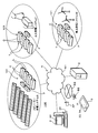
- FIG. 1 is a diagram showing an outline of the remote monitoring system 100.
- the remote monitoring system 100 enables remote access to information regarding the storage element groups included in the mega solar power generation system S, the thermal power generation system F, and the wind power generation system W.
- a power conditioner (PCS: Power Conditioning System) P and a power storage system 101 are installed in parallel with the mega solar power generation system S, the thermal power generation system F, and the wind power generation system W.
- the power storage system 101 is configured by arranging a plurality of containers C containing the power storage module group L side by side.
- the power storage module group L includes a plurality of power storage elements.
- the power storage element is preferably a rechargeable battery such as a secondary battery such as a lead storage battery or a lithium ion battery or a capacitor. Part of the power storage element may be a non-rechargeable primary battery.
- the communication device 1 (see FIGS. 2 and 3) is mounted/connected to each of the power storage system 101 or the device (P and management device M described later) in the power generation systems S, F, and W to be monitored. To be done.
- the remote monitoring system 100 is a communication medium between a communication device 1, a server device 2 (data processing device) that collects information from the communication device 1, a client device 3 for browsing the collected information, and a device. And network N.
- the communication device 1 may be a terminal device (measurement monitor) that communicates with a battery management device (BMU: Battery Management Unit) provided in the power storage element to receive information on the power storage element, or ECHONET/ECHONET Lite (registered trademark). It may be a corresponding controller.
- the communication device 1 may be an independent device, or may be a network card type device that can be mounted on the power conditioner P or the power storage module group L.
- the communication device 1 is provided for each group of a plurality of power storage modules in order to acquire information on the power storage module group L in the power storage system 101.
- a plurality of power conditioners P are connected so that serial communication is possible, and the communication device 1 is connected to a control unit of any one of the representative power conditioners P.
- the server device 2 includes a Web server function, and presents information obtained from the communication device 1 mounted/connected to each device to be monitored according to access from the client device 3.
- the network N includes a public communication network N1 which is the so-called Internet and a carrier network N2 which realizes wireless communication according to a predetermined mobile communication standard.
- the public communication network N1 includes a general optical line, and the network N includes a dedicated line to which the server device 2 is connected.
- the network N may include an ECHONET/ECHONET Lite compatible network.
- the carrier network N2 includes a base station BS, and the client device 3 can communicate with the server device 2 via the network N from the base station BS.
- An access point AP is connected to the public communication network N1, and the client device 3 can transmit/receive information to/from the server device 2 from the access point AP via the network N.
- the power storage module group L of the power storage system 101 has a hierarchical structure.
- the communication device 1 that transmits the information of the power storage element to the server device 2 acquires the information of the power storage module group from the management device M provided in the power storage module group L.
- FIG. 2 is a diagram showing an example of a hierarchical structure of the power storage module group L and a connection form of the communication device 1.
- the power storage module group L is, for example, a power storage module (also referred to as a module) in which a plurality of power storage elements (also referred to as power storage cells or cells; a plurality of electrode bodies (elements) may be present in the power storage element) are connected in series.
- a bank in which a plurality of power storage modules are connected in series and a domain in which a plurality of banks are connected in parallel are configured.
- the management device M is provided for each of the banks with the numbers (#) 1-N and for each domain in which the banks are connected in parallel.
- the management device M provided for each bank communicates by serial communication with a control board (CMU: Cell Monitoring Unit) with a communication function, which is built into each power storage module, and performs measurement on the power storage cells inside the power storage module. Acquire data (voltage, current, temperature, etc.).
- the bank management device M performs balance adjustment for each bank based on the acquired measurement data for each power storage cell, and executes management processing such as detection of an abnormality in the communication state.
- the management device M of each bank transmits the measurement data obtained from the power storage module of each bank to the management device M provided for each domain.
- the management device M of the bank transmits the balance adjustment status of the power storage module to the management device M of the domain, and notifies the management device M of the domain when an abnormality is detected.
- the management device M of the domain collects the measurement data, the detected abnormality, and other information obtained from the management device M of the bank belonging to the domain.
- the communication device 1 is connected to the domain-based management apparatus M.
- the domain management device M and the bank management device M may be the same (management device M integrated into one).
- the communication device 1 includes a control unit 10, a storage unit 11, a first communication unit 12, and a second communication unit 13.
- the control unit 10 is a processor that uses a CPU (Central Processing Unit), and controls each component using a memory such as a built-in ROM (Read Only Memory) and RAM (Random Access Memory) to execute processing.
- CPU Central Processing Unit
- RAM Random Access Memory
- the storage unit 11 uses a nonvolatile memory such as a flash memory.
- the storage unit 11 stores a device program read and executed by the control unit 10.
- the device program 1P includes a communication program conforming to SSH (Secure Shell), SNMP (Simple Network Management Protocol) and the like.
- the storage unit 11 stores information such as information collected by the processing of the control unit 10 and an event log.
- the information stored in the storage unit 11 can also be read out via a communication interface such as a USB whose terminals are exposed in the housing of the communication device 1.
- the first communication unit 12 is a communication interface that realizes communication with the monitoring target device to which the communication device 1 is connected.
- the first communication unit 12 uses, for example, a serial communication interface such as RS-232C or RS-485.
- the power conditioner P includes a control unit having a serial communication function based on RS-485, and the first communication unit 12 communicates with the control unit.
- the control boards provided in the power storage module group L are connected by a CAN (Controller Area Network) bus and communication between the control boards is realized by CAN communication
- the first communication unit 12 is a communication interface based on the CAN protocol. ..
- the first communication unit 12 may be a communication interface compatible with the ECHONET/ECHONET Lite standard.
- the second communication unit 13 is an interface that realizes communication via the network N, and uses a communication interface such as Ethernet (registered trademark) or a wireless communication antenna.
- the control unit 10 can be communicatively connected to the server device 2 via the second communication unit 13.
- the second communication unit 13 may be a communication interface compatible with the ECHONET/ECHONET Lite standard.
- the control unit 10 acquires, via the first communication unit 12, the measurement data for the power storage element obtained by the device to which the communication device 1 is connected.
- the control unit 10 functions as an SNMP agent by reading and executing the SNMP program, and can also respond to the information request from the server device 2.
- the client device 3 is a computer used by an operator such as a manager or a person in charge of maintenance of the power storage system 101 of the power generation systems S, F, and W.
- the client device 3 may be a desktop or laptop personal computer, or a so-called smartphone or tablet communication terminal.
- the client device 3 includes a control unit 30, a storage unit 31, a communication unit 32, a display unit 33, and an operation unit 34.
- the control unit 30 is a processor using a CPU.
- the control unit 30 causes the display unit 33 to display the Web page provided by the server device 2 or the communication device 1 based on the client program 3P including the Web browser stored in the storage unit 31.
- the storage unit 31 uses a non-volatile memory such as a hard disk or a flash memory.
- Various programs including the client program 3P are stored in the storage unit 31.
- the client program 3P may be a copy of the client program 6P stored in the recording medium 6 and read in the storage unit 31.
- the communication unit 32 uses a communication device such as a network card for wired communication, a wireless communication device for mobile communication connected to the base station BS (see FIG. 1), or a wireless communication device compatible with connection to the access point AP. ..
- the control unit 30 can perform communication connection or information transmission/reception with the server device 2 or the communication device 1 via the network N by the communication unit 32.
- the display unit 33 uses a display such as a liquid crystal display or an organic EL (Electro Luminescence) display.
- the display unit 33 displays the image of the Web page provided by the server device 2 or the communication device 1 by the process based on the client program 3P of the control unit 30.
- the display unit 33 is preferably a display with a built-in touch panel, but may be a display without a built-in touch panel.
- the operation unit 34 is a user interface such as a keyboard and pointing device capable of inputting/outputting with the control unit 30 or a voice input unit.
- the operation unit 34 may use the touch panel of the display unit 33 or a physical button provided on the housing.
- the operation unit 34 notifies the control unit 30 of operation information by the user.
- the server device 2 uses a server computer and includes a control unit 20, a storage unit 21, and a communication unit 22.
- the server device 2 is described as one server computer, but the processing may be distributed among a plurality of server computers.
- the control unit 20 is a processor that uses a CPU or a GPU (Graphics Processing Unit), uses a built-in memory such as ROM and RAM, and controls each component to execute processing.
- the control unit 20 executes communication and information processing based on the server program 21P stored in the storage unit 21.
- the server program 21P includes a Web server program, and the control unit 20 functions as a Web server that provides a Web page to the client device 3.
- the control unit 20 collects information from the communication device 1 as an SNMP server based on the server program 21P.
- the control unit 20 executes data processing on the measurement data collected based on the data processing program 22P stored in the storage unit 21.
- the storage unit 21 uses a non-volatile memory such as a hard disk or a flash memory.
- the storage unit 21 stores the server program 21P and the data processing program 22P described above.
- the storage unit 21 stores the determination model 2M used in the processing based on the data processing program 22P.
- the storage unit 21 stores the measurement data of the power conditioner P and the power storage module group L of the power storage system 101, which is a monitoring target, collected by the process of the control unit 20.
- the server program 21P, the data processing program 22P, and the determination model 2M stored in the storage unit 21 read the server program 51P, the data processing program 52P, and the determination model 5M stored in the recording medium 5 and copy them to the storage unit 21. It may be the one.
- the communication unit 22 is a communication device that realizes communication connection and information transmission/reception via the network N.
- the communication unit 22 is a network card compatible with the network N.
- the communication device 1 acquires from the management apparatus M after the previous timing every time the communication device 1 has a predetermined timing (for example, a constant cycle or a data amount satisfies a predetermined condition).
- the stored measurement data for each power storage cell and other information are transmitted to the server device 2.
- the communication device 1 transmits the measurement data in association with the storage cell identification information (number).
- the communication device 1 may transmit all sampling data obtained via the management apparatus M, may transmit measurement data thinned out at a predetermined ratio, or may transmit an average value.
- the server device 2 acquires the information including the measurement data from the communication device 1, and associates the acquired measurement data with the acquisition time information and the information for identifying the device (M, P) from which the information is acquired.
- a predetermined timing for example, a constant cycle or a data amount satisfies a predetermined condition.
- the server device 2 can present the latest data out of the stored measurement data for each power storage cell of the power storage system 101 according to the access from the client device 3.
- the server device 2 can also use the measurement data for each power storage cell and present the state for each bank or domain for each power storage module.
- the server device 2 uses the measurement data to perform abnormality diagnosis of the power storage system 101, health check, estimation of SOC of the power storage module, SOH (State of Health), etc., or life prediction, It is possible to present the implementation results.
- the server device 2 When performing the above-described diagnosis, estimation, or prediction process, the server device 2 according to the present disclosure specifies, from the measurement data of the storage cell, the measurement data of a different storage cell based on the data processing program 22P and the determination model 2M. .. The server device 2 performs diagnosis, estimation, or prediction for each power storage module, bank, or domain using other measurement data other than the specified measurement data.
- FIG. 5 is a flowchart showing an example of a data processing procedure by the server device 2.
- the control unit 20 of the server device 2 periodically executes the processing procedure described below for each target storage element group.
- the execution cycle is longer than the cycle in which the measurement data is transmitted from the communication device 1.
- a target power storage element group is a bank connecting a plurality of modules, a domain including a plurality of banks in parallel, and a power storage system 101 including a plurality of domains.
- the large-scale power storage system 101 includes 10 banks in each of 8 domains, in which 12 modules each including 12 power storage cells are connected in series. In this case, the number of storage cells is about 12000.
- the control unit 20 reads out the measurement data group stored in association with the time information for each of the power storage cells included in the power storage system 101 to be processed (step S1), and a different power storage cell from the read measurement data group.
- the measurement data of is specified (step S2).
- the control unit 20 excludes the specified measurement data from the read measurement data group (step S3), and uses the remaining measurement data group to execute the estimation process of the deterioration state (SOH) of the entire power storage system 101 ( Step S4).
- the control unit 20 stores the result of the estimation process of step S4 in the storage unit 21 in association with the time information when the latest data in the measurement data group is acquired and the information that identifies the power storage system 101 (step S5). The process ends.
- the deterioration state estimation process is performed based on the data excluding the measurement data of different power storage cells.
- a large-scale power storage system 101 including a plurality of domains in which banks in which a large number of power storage cells are connected in series are connected in parallel, measurement data of a different power storage cell is excluded from a group of power storage cells to obtain an assumed model.
- the accuracy of the processing result is improved by performing the estimation process of the deterioration state of the electricity storage cell group having a regular life.
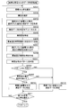
- FIG. 6 is a flowchart showing an example of processing for identifying a different power storage cell.
- the flowchart of FIG. 6 corresponds to the details of step S2 in the flowchart of FIG. That is, the processing procedure shown in the flowchart of FIG. 6 is repeatedly executed periodically.
- the control unit 20 specifies by determining whether or not the power storage cell group includes a different power storage cell for each power storage cell group including the different power storage cells.
- control unit 20 selects one storage cell group (step S201).
- control unit 20 selects a storage cell group in module units, that is, module identification information.
- the control unit 20 selects the attribute of the target measurement data (step S202).
- the attribute is the type of measurement data such as voltage, current, and temperature.
- the attribute is not limited to this, and may be other data that can be measured for each storage cell or module.
- the control unit 20 obtains the latest measurement data of the attribute selected in step S202 for each of the plurality of storage cells included in the storage cell group selected in step S201 (step S203).
- the measurement data acquired in step S203 may be acquired by thinning out the measurement data read out in step S1 of FIG. 5 at intervals of time according to the length of a predetermined past period described later.
- the measurement data acquired in step S203 is input to the judgment model 2M for each attribute (step S204), and the heterogeneity output from the judgment model 2M is specified (step S205).
- the control unit 20 stores the heterogeneity specified in step S205 in the storage unit 21 in association with the information for identifying the storage cell group selected in step S201 and the time information of the acquired measurement data (step S206).
- the control unit 20 reads out the degree of heterogeneity in the past predetermined period stored in the storage unit 21 for the power storage cell group selected in step S201 (step S207).
- the control unit 20 creates a time distribution of the heterogeneity in the past predetermined period (step S208).
- the control unit 20 determines that the storage cell group selected in step S201 is heterogeneous based on the value of the degree of heterogeneity read in step S207, the time distribution created in step S208, and/or the measurement data of the selected storage cell group. It is determined whether or not the storage cell is included (step S209).
- the control unit 20 specifies that the measurement data of the storage cell group selected in step S201 is the measurement data of the different storage cell ( Step S210).
- the control unit 20 determines whether or not all the storage cell groups have been selected in step S201 (step S211), and when it is determined that all have selected (S211: YES), the process proceeds to step S3 in the flowchart of FIG. Return to.
- step S209 When it is determined in step S209 that the power storage cell does not include a different power storage cell (S209: NO), the control unit 20 determines that the data is not the measurement data of the different power storage cell (step S212), and the process proceeds to step S211.
- step S211 If it is determined in step S211 that all the storage cell groups have not been selected (S211: NO), the control unit 20 returns the process to step S201 and selects the next storage cell group (S201).
- control unit 20 determines whether or not the different storage cells are included in the module unit in which the storage cells are connected in series.
- the unit of the storage cell group to be determined may be determined according to the design of the determination model 2M.
- the determination may be made on a bank-by-bank basis or on an individual storage cell basis.
- FIG. 7 is a schematic diagram of an example of the determination model 2M.
- the determination model 2M is a classifier that uses a convolutional neural network to classify a storage cell group including standard storage cells that are not different from each other and a storage cell group including other storage cells that are different from each other.
- the determination model 2M includes an input layer 201 that inputs the voltage value of each storage cell of the selected storage cell group, and an output layer 202 that outputs a score related to the heterogeneity based on the input voltage value.
- an intermediate layer 203 including a convolutional layer or a pooling layer.
- the determination model 2M is a neural network of teacher data including measurement data with a label (for example, “0”) that is a standard storage cell that is not foreign and measurement data with a foreign label (for example, “1”). It is given to and learned for each attribute of measurement data. In the example of FIG. 7, the attribute of the voltage value measured in each storage cell is learned.
- the determination model 2M outputs, from the output layer 202, a heterogeneity score (a numerical value between 0 and 1) classified as heterogeneous with respect to the given measurement data.
- the judgment model 2M is not limited to a classifier, but may be a convolutional neural network that outputs a feature amount.
- the determination model 2M may be configured by a network using a recurrent neural network that inputs time series data of measurement data of the same power storage cell and outputs a feature amount, an LSTM (Long Short-term Memory), or the like.
- the teacher data of the determination model 2M is not only attribute-based but also the environment of the power storage system 101 to be measured data, the type of the power generation system connected to the power storage system 101, or the load of the output destination from the power storage system 101 in advance. May be sorted according to the type.
- the judgment model 2M is classified into a plurality of different judgment models 2Ma, judgment models 2Mb,... Based on the separated teacher data, and the model is selected according to the type of the storage cell to be judged.
- the control unit 20 may re-learn the determination model 2M again with the measurement data group excluding the heterogeneous measurement data identified by the processing procedure shown in the flowchart of FIG.
- the control unit 20 causes the ratio of the heterogeneous measurement data specified by the processing procedure shown in the flowchart of FIG. 6 to the measurement data of all the storage cell groups to exceed a predetermined ratio (for example, 20%). In this case, it is advisable to re-learn the determination model 2M assuming that all the measurement data are the measurement data of the electricity storage cell group that does not include a different electricity storage cell.
- the determination model 2M changes over time as the entire power storage system 101 including the storage cell group changes over time, erroneous determinations can be avoided, and appropriate determination can be made for the appearance of different and different power storage cells that appear over time. Be expected.
- the determination model 2M may be stored in another non-volatile storage medium according to the number of years, such as 1 year, 2 years, and applied to the change over time of another power storage system 101. Good.
- the determination model 2M uses the average, standard deviation, median, etc. of the measurement data to statistically determine whether or not the measurement data that is an outlier is included and the outlier degree when it is included. It may be a model to be calculated. In another example, the determination model 2M may be a model that obtains a trend from time-series data of measurement data and outputs a score indicating the degree of heterogeneity based on the difference in the trend. In another example, the determination model 2M uses a k-nearest neighbor algorithm, and the control unit 20 classifies the target measurement data into a non-heterogeneous class previously learned based on teacher data and a heterogeneous class. It may be determined to which of the above.
- the determination model 2M may use the k-means method or the EM method, and the control unit 20 may perform clustering determination based on the determination model 2M (determination program).
- the judgment model 2M (judgment program) uses PCA (Principal Component Analysis; principal component analysis), and the control unit 20 contracts the target measurement data and judges whether or not it is heterogeneous. May be.
- step S209 determination of whether or not a different power storage cell is included based on the value of the degree of heterogeneity, the time distribution, and/or the measurement data of the selected power storage cell group in step S209. The procedure will be described in detail.
- control unit 20 graphs and outputs the time distribution of the degree of heterogeneity created for each selected storage cell group, and accepts the operator's determination as to whether or not a different storage cell is included.
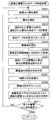
- FIG. 8 is a flowchart showing a procedure of determining whether or not the storage cell is included in the first example.
- control unit 20 of the server device 2 Each time the control unit 20 of the server device 2 creates a time distribution for each storage cell group (module) in step S208, the control unit 20 stores the time distribution in association with the time information in the storage unit 21 (step S181). After determining that all the storage cell groups have been selected in step S211, the control unit 20 reads the time distribution of all the storage cell groups stored in the storage unit 21 (step S182).
- the control unit 20 sorts the read time distributions of the respective storage cell groups in descending order of the maximum value or average value of the heterogeneity (step S183).
- the control unit 20 sequentially graphs the sorted time distribution of each storage cell group, that is, the distribution of the degree of heterogeneity over time, and displays screen data including a selection reception screen as to whether or not a different storage cell is included for each. It is created (step S184) and notified to the operator (step S185).
- the screen created in step S184 includes measurement data (voltage value, current value, temperature value) data for each storage cell group.
- the time distribution of the electricity storage cell group in which the maximum value or the average value of the heterogeneity is less than the predetermined value and the possibility of including the different electricity storage cells is low. It need not be included.
- a storage cell group having a maximum or average heterogeneity value less than a predetermined value is determined not to include a different storage cell.
- the control unit 30 of the client device 3 requests the server device 2 for the screen data (step S311). ..
- the control unit 20 of the server device 2 receives the request (step S186), and transmits the screen data created in step S184 to the client device 3 in response to the request (step S187).
- the control unit 20 transmits the screen data of the time distribution of the heterogeneity created based on the latest measurement data.
- the control unit 20 may transmit the screen data of the time distributions created up to that point in time.
- the control unit 30 receives the data on the screen (step S312), draws a graph of the time distribution of the degree of heterogeneity for each power storage cell group (module) based on the received data, and selects it. It outputs to the display part 33 with a reception screen (step S313).
- the operator visually confirms the graph of the time distribution of the heterogeneity of the storage cell groups sorted in the descending order of the maximum value or the average value of the heterogeneity on the display unit 33, and analyzes the measurement data displayed together on the screen. Therefore, it is determined whether or not a foreign cell is included.
- the operator reflects the result of the determination as to whether or not a different power storage cell is included on the selection acceptance screen.
- the control unit 30 accepts a selection for each storage cell group of whether or not the operator includes different storage cells on the selection acceptance screen (step S314), and transmits the accepted selection data to the server device 2 (step S315). ).
- the control unit 20 of the server device 2 receives the selection data (step S188), and identifies whether or not a different storage cell is included for each storage cell group based on the operator's selection indicated by the data (step S189). ), the processing ends.
- control unit 20 may specify that the storage cell group for which it is not selected whether or not to include a different storage cell does not include a different storage cell.
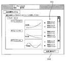
- FIG. 9 is an example of a screen including a graph of time distribution of heterogeneity.
- the time distribution of the degree of heterogeneity for each storage cell group (module) is displayed in the sorted order on the display unit 33 of the client device 3 used by the operator.
- a radio control 331 that allows the operator to select whether to include a different power storage cell is displayed beside the graph.
- the control unit 30 of the client device 3 accepts the selection by each radio control 331 (S314), and accepts the selection.
- the selected data is transmitted to the server device 2.
- the control unit 20 determines whether or not a heterogeneous storage cell is included by analyzing the created time distribution pattern of the heterogeneity. Referring to the time distribution of the heterogeneity shown in FIG. 9, pattern A of module #11 in which the heterogeneity simply increases and exceeds a predetermined value, and module #11 in which the heterogeneity exceeds a predetermined value but decreases There is a pattern B of 5 and a pattern C of the module #6 in which the degree of heterogeneity decreases after exceeding a predetermined value but simply increases again.
- the degree of heterogeneity exceeds a predetermined value, but it gradually becomes balanced and familiar with the surrounding power storage cells, and it is determined that it does not include a different power storage cell to be excluded. Since it cannot be determined at this time whether the pattern C becomes the pattern A or the pattern B after a lapse of time, it is determined that only the pattern A is the time distribution of the heterogeneity of the storage cell group including the storage cells that are different from each other. To do.
- FIG. 10 is a flowchart showing a procedure for determining whether or not the storage cell in the second example is included.
- the processing procedure shown in the flowchart of FIG. 10 is a detailed description of the processing of step S209 in the flowchart of FIG.
- the same steps as those in the flowchart of FIG. 6 are designated by the same step numbers, and detailed description thereof will be omitted.
- the control unit 20 of the server device 2 determines whether the ascending/descending pattern of the heterogeneity in the time distribution created in step S208 is the pattern A, the pattern B, or the pattern C that has been classified in advance (step S281). ..
- the control unit 20 determines whether or not the pattern A is determined in step S281 (step S282), and when it is determined that the pattern A is not determined (S282: NO), the process proceeds to step 212.
- step S281 the control unit 20 determines that the maximum value or the average value of the past heterogeneity read in step S207 is the first predetermined value or more, Moreover, it is determined whether or not the differential value (change with time) of the heterogeneity in the pattern A is equal to or larger than the second predetermined value (step S283).
- step S283 When it is determined in step S283 that the maximum value or the average value of the heterogeneity is equal to or larger than the first predetermined value and the differential value of the heterogeneity in the pattern A is equal to or larger than the second predetermined value (S283: YES).
- the control unit 20 advances the process to step S210.
- step S283 When it is determined that the maximum value or the average value is less than the first predetermined value or the differential value of the heterogeneity is less than the second predetermined value in step S283 (S283: NO), the control unit 20 , The process proceeds to step S212.
- the control unit 20 images the created time distribution of the degree of heterogeneity, and determines whether or not a heterogeneous power storage cell is included using an image determination model that is a classifier that uses a neural network for the image.
- FIG. 11 is a schematic diagram of the image determination model 22M based on the imaged time distribution.
- the image determination model 22M is a neural network that includes an intermediate layer that includes a convolutional layer or a pooling layer that extracts a feature amount.
- the image determination model 22M is a storage cell that is different from the measured data related to the time distribution.
- the accuracy (score) including the measurement data is output.
- the image determination model 22M may be stored in the storage unit 21 of the server device 2 together with the determination model 2M. As shown in FIG. 11, the image determination model 22M is learned by teacher data that is a pair of an image of the time distribution and a result determined by the operator.
- the image determination model 22M may be learned as a model for determining the heterogeneity of different power storage cells when teacher data can be collected. For example, a model that determines which of the pattern A, the pattern B, and the pattern C in FIG. 11 may be used.
- the control unit 20 may determine the heterogeneity based on the value of the degree of heterogeneity used in the determination of step S209, the time distribution created in step S208, and/or the measurement data of the selected power storage cell group. ..
- the control unit 20 may specify the degree of heterogeneity, that is, how much it deviates from a standard power storage cell.
- control unit 20 uses the image determination model 22M to determine whether the foreign substance is a “new storage cell” or “a storage cell having a higher quality (longer life) than a standard storage cell”, and Heterogeneity may be determined, for example, whether the battery is a battery having a shorter life than a standard battery.
- FIG. 12 is a flowchart showing the procedure for determining whether or not the storage cell is included in the third example.
- the processing procedure shown in the flowchart of FIG. 12 is a detailed description of the processing of step S209 in the flowchart of FIG.
- the same steps as those in the flowchart of FIG. 6 are designated by the same step numbers, and detailed description thereof will be omitted.
- the control unit 20 of the server device 2 images the time distribution created in step S208 (step S381), and inputs the imaged time distribution to the image determination model 22M that has been learned in advance (step S382).
- the control unit 20 identifies whether or not the target power storage cell group includes a different power storage cell based on the score output from the image determination model 22M (step S383), and advances the process to step S211.
- the server device 2 can create and transmit the screen information by the information presentation function in the remote monitoring system 100.
- the control unit 20 of the server device 2 automatically determines in each of the above-described second or third examples to include a different storage cell for each storage cell group, which storage cell group has a different storage cell. It is possible to transmit to the client device 3 a screen that allows the user to visually recognize whether or not it is included.
- the control unit 20 of the server device 2 creates the screen for visually recognizing the storage cell group including the different storage cells. Therefore, in the determination process for each storage cell group (FIG. 6, FIG. 10, or FIG. 12), the latest When it is determined based on the measurement data of 1. that the different storage cells are included, it is stored in association with the identification information of the storage cell group that the storage cells include the different storage cells. Even if it is determined that the different storage cells are included, if the respective patterns can be identified as in the first example or the second example, the control unit 20 determines which pattern. It is stored in the storage unit 21 together with the information for identifying that.
- FIG. 13 is a flowchart showing an example of a processing procedure of information presentation in the server device 2.
- the control unit 20 of the server device 2 receives the identification information of the target power storage system 101 from the client device 3 (step S301) and stores it for each power storage cell group included in the power storage system 101 corresponding to the received identification information.
- the result of determination as to whether or not a certain different type of storage cell is included is read (step S302).
- the control unit 20 creates a screen that is a graphic representation of the read determination result (step S303), transmits the data of the created screen to the client device 3 (step S304), and ends the process.
- step S303 for example, as shown in FIG. 14, the determination result is created as a chart for each storage cell group. Other graphs may be used.
- the processes of steps S302 to S303 may be sequentially performed regardless of the request from the client device 3, store the latest screen data in the storage unit 21, and transmit when the request is satisfied (S304).
- FIG. 14 shows an example of a screen including the determination result as to whether or not a different power storage cell is included.
- a table having identification information (identification numbers) of banks and modules in rows or columns corresponds to a storage cell group (module) including different storage cells.
- the cells to be highlighted are highlighted by hatching. In this way, it is possible to visually recognize which of the storage cell groups including different storage cells is present, and the storage cells at the stage before the abnormality occurs or when observation is necessary such as when a new storage cell is added. It is also possible to let the operator know the state of.
- the hatching type is changed and displayed according to the heterogeneity or the degree of the heterogeneity. When the heterogeneity can be discriminated by the second or third example described above, the heterogeneity can be displayed separately as shown in FIG.
- the management device M of the power storage system 101 having a hierarchical structure of domains, banks, and modules may perform the process of specifying measurement data of different power storage cells.
- the process of state diagnosis, deterioration estimation, or life prediction in the power storage system 101 including power storage elements having a hierarchical structure of domains and banks has been described.
- the same process can be applied when the power storage module group L in which a plurality of power storage elements included in the uninterruptible power supply U and the rectifier D are connected in parallel.
Landscapes
- Engineering & Computer Science (AREA)
- Physics & Mathematics (AREA)
- Theoretical Computer Science (AREA)
- General Physics & Mathematics (AREA)
- Software Systems (AREA)
- Computing Systems (AREA)
- Mathematical Physics (AREA)
- Artificial Intelligence (AREA)
- General Engineering & Computer Science (AREA)
- Data Mining & Analysis (AREA)
- Evolutionary Computation (AREA)
- Biophysics (AREA)
- Molecular Biology (AREA)
- General Health & Medical Sciences (AREA)
- Computational Linguistics (AREA)
- Biomedical Technology (AREA)
- Life Sciences & Earth Sciences (AREA)
- Health & Medical Sciences (AREA)
- Chemical & Material Sciences (AREA)
- Manufacturing & Machinery (AREA)
- Chemical Kinetics & Catalysis (AREA)
- Electrochemistry (AREA)
- General Chemical & Material Sciences (AREA)
- Computer Vision & Pattern Recognition (AREA)
- Medical Informatics (AREA)
- Power Engineering (AREA)
- Microelectronics & Electronic Packaging (AREA)
- Charge And Discharge Circuits For Batteries Or The Like (AREA)
- Tests Of Electric Status Of Batteries (AREA)
- Secondary Cells (AREA)
- Remote Monitoring And Control Of Power-Distribution Networks (AREA)
Abstract
データ処理装置は、蓄電素子に対する測定データを処理するデータ処理装置であって、前記蓄電素子毎、又は、複数の前記蓄電素子をグループ分けした蓄電素子群毎に測定された測定データが入力された場合に、前記測定データに異質な蓄電素子の測定データが含まれているか否かに対応するスコアを出力するように学習された判定モデルを記憶した記憶部と、取得した測定データを前記判定モデルへ入力して出力されたスコアに基づいて異質な蓄電素子の測定データを特定する特定部とを備える。
Description
本発明は、蓄電素子群に関する測定データを用いた演算を行なうデータ処理装置、データ処理方法、及びコンピュータプログラムに関する。
蓄電素子は、無停電電源装置、安定化電源に含まれる直流又は交流電源装置等に広く使用されている。また、再生可能エネルギー又は既存の発電システムにて発電された電力を蓄電しておく大規模なシステムでの蓄電素子の利用が拡大している。
蓄電素子を使用したシステムでは、蓄電素子の状態診断、充電状態(SOC:State Of Charge)の推定、又は寿命予測等の実施を含む保守活動が重要になる。蓄電素子の状態診断、推定又は寿命予測の方法については、蓄電素子の充放電時に測定される電圧、電流、温度等の測定データを用いる方法を始めとして種々提案され、精度向上が図られている(特許文献1等)。
上述したような蓄電素子の状態診断、推定又は寿命予測の方法は、製造時に想定されている蓄電素子モデルに基づいて確立されている。しかしながら個々の蓄電素子は、素材の性質、製造バラつき等を持っており、時間の経過又は使用環境によって蓄電素子モデルの性質から外れた異質性を出現させる。例えば、製造時には他の蓄電素子と同様の特性を有している蓄電素子であっても、想定されているモデルよりも格段に高寿命な蓄電素子、又は低寿命な蓄電素子である可能性がある。そして、蓄電素子は、充放電の繰り返しによって満充電容量が低下していくという性質を有している。同一の期間に同様の充放電の履歴を有する蓄電素子群に対し、新しい蓄電素子又は異なる履歴を有する蓄電素子を加えた場合、この新しい又は異なる履歴の蓄電素子は、蓄電素子群にとっては異質である。この異質さの程度を判定モデルによって定量的な尺度で示したものを異質度と称する。
膨大な量の蓄電素子を接続して用いるシステム全体としての状態診断、推定又は寿命予測を実施する場合、蓄電素子群の測定データに、異質な蓄電素子の測定データが含まれている場合、診断、推定又は予測の誤差は拡大する。
本発明は、蓄電素子に関する測定データに基づく前記蓄電素子に関する診断、推定、予測の精度を向上させるデータ処理装置、データ処理方法、及びコンピュータプログラムを提供することを目的とする。
データ処理装置は、蓄電素子に対する測定データを処理するデータ処理装置であって、前記蓄電素子毎、又は、複数の前記蓄電素子をグループ分けした蓄電素子群毎に測定された測定データが入力された場合に、前記測定データに異質な蓄電素子の測定データが含まれているか否かに対応するスコアを出力するように学習された判定モデルを記憶した記憶部と、取得した測定データを前記判定モデルへ入力して出力されたスコアに基づいて異質な蓄電素子の測定データを特定する特定部とを備える。
データ処理装置は、蓄電素子に対する測定データを処理するデータ処理装置であって、前記蓄電素子毎、又は、複数の前記蓄電素子をグループ分けした蓄電素子群毎に測定された測定データが入力された場合に、前記測定データに異質な蓄電素子の測定データが含まれているか否かに対応するスコアを出力するように学習された判定モデルを記憶した記憶部と、取得した測定データを前記判定モデルへ入力して出力されたスコアに基づいて異質な蓄電素子の測定データを特定する特定部とを備える。
上記構成により、異質な蓄電素子の測定データを除外した残りの測定データを用いた処理が可能になる。
残りの測定データを用いた処理は例えば、蓄電素子の異常の有無を含む状態診断、劣化状態推定、又は寿命予測の処理である。異質な蓄電素子の測定データを除外することにより、製造時に想定されている蓄電素子モデルに基づいて確立されているこれらの処理の精度を向上させることができる。
異質な蓄電素子の測定データの特定に用いられる判定モデルは、測定データの属性別、例えば電圧、電流又は温度等、製造時に想定されている蓄電素子モデルに関するデータの種類別に学習されている。新品なのか、長寿命なのか、短寿命なのか、その他の性質が異なるのか等のどのように異質なのかという異質性毎に、異なる属性の測定データへ影響する可能性があるから、属性別に判定することによって異質であることの判定が精度よく実施される。
判定モデルの出力自体に基づいて断続的に、測定データ夫々に対して異質な蓄電素子の測定データが含まれているか否かを判定する方法の他、出力の経時変化を用いて異質な蓄電素子の測定データであるか否かを判定してもよい。この場合、他の蓄電素子とバランス調整して経時的に馴染む蓄電素子の測定データを誤って、或いは早まって異質な蓄電素子の測定データと特定することを回避することができる。
判定モデルの出力の時間分布に対する異質な蓄電素子の測定データを含むか否かの判定は、データが十分に収集されるまでは、オペレータによる判断に基づいて行なわれてもよい。予め時間分布のパターンを分析しておき、いずれのパターンに当てはまるかによって異質な蓄電素子の測定データを含むか否かを正確に判定してもよい。時間分布のパターンを画像化した画像を入力し、異質な蓄電素子の測定データを含むか否かを出力する分類器モデルを用いて判定してもよい。
判定モデルは、異質であると特定された測定データ以外の残りの測定データを用いて再学習することで、実際に運用される蓄電素子の特性に適合する。
判定モデルは、異質であると特定される測定データが全体の所定の割合以上となった場合に再学習されてもよい。時間の経過と共に容量等が変化する蓄電素子に対し、判定モデルも共に経時変化させることが可能である。
データ処理方法は、蓄電素子に対する測定データを処理するデータ処理方法であって、前記蓄電素子毎、又は、複数の前記蓄電素子をグループ分けした蓄電素子群毎に測定された測定データが入力された場合に、前記測定データに異質な蓄電素子の測定データが含まれているか否かに対応するスコアを出力するように学習された判定モデルを用い、取得した測定データを前記判定モデルへ入力して出力されたスコアに基づいて異質な蓄電素子の測定データを特定する。
コンピュータプログラムは、コンピュータに、蓄電素子毎、又は、複数の前記蓄電素子をグループ分けした蓄電素子群毎に測定された測定データが入力された場合に、前記測定データに異質な蓄電素子の測定データが含まれているか否かに対応するスコアを出力するように学習された判定モデルを用い、取得した測定データを前記判定モデルへ入力して出力されたスコアに基づいて異質な蓄電素子の測定データを特定する処理を実行させる。
本発明をその実施の形態を示す図面を参照して具体的に説明する。
図1は、遠隔監視システム100の概要を示す図である。遠隔監視システム100は、メガソーラー発電システムS、火力発電システムF、風力発電システムWに含まれる蓄電素子群におけるに関する情報への遠隔からのアクセスを可能とする。
メガソーラー発電システムS、火力発電システムF及び風力発電システムWには、パワーコンディショナ(PCS:Power Conditioning System )P及び蓄電システム101が並設されている。蓄電システム101は、蓄電モジュール群Lを収容したコンテナCを複数並設して構成されている。蓄電モジュール群Lは、複数の蓄電素子を含む。蓄電素子は、鉛蓄電池及びリチウムイオン電池のような二次電池や、キャパシタのような、再充電可能なものであることが好ましい。蓄電素子の一部が、再充電不可能な一次電池であってもよい。
遠隔監視システム100では、監視対象となる発電システムS,F,Wにおける蓄電システム101、又は装置(Pおよび後述の管理装置M)夫々に、通信デバイス1(図2,3参照)が搭載/接続される。遠隔監視システム100は、通信デバイス1と、通信デバイス1から情報を収集するサーバ装置2(データ処理装置)と、収集された情報を閲覧するためのクライアント装置3と、装置間の通信媒体であるネットワークNとを含む。
通信デバイス1は、蓄電素子に備えられる電池管理装置(BMU:Battery ManagementUnit )と通信して蓄電素子の情報を受信する端末装置(計測モニタ)であってもよいし、ECHONET /ECHONETLite (登録商標)対応のコントローラであってもよい。通信デバイス1は、独立したデバイスであってもよいし、パワーコンディショナPや蓄電モジュール群Lに搭載可能なネットワークカード型のデバイスであってもよい。通信デバイス1は、蓄電システム101における蓄電モジュール群Lの情報を取得すべく、複数の蓄電モジュールからなるグループ毎に1つずつ設けられている。パワーコンディショナPは複数台でシリアル通信が可能に接続されており、通信デバイス1は、いずれか代表となるパワーコンディショナPの制御ユニットに接続されている。
サーバ装置2はWebサーバ機能を含み、監視対象の各装置に搭載/接続された通信デバイス1から得られる情報を、クライアント装置3からのアクセスに応じて提示する。
ネットワークNは、所謂インターネットである公衆通信網N1と、所定の移動通信規格による無線通信を実現するキャリアネットワークN2とを含む。公衆通信網N1は、一般光回線を含み、ネットワークNは、サーバ装置2が接続する専用線を含む。ネットワークNは、ECHONET /ECHONETLite 対応のネットワークを含んでもよい。キャリアネットワークN2には基地局BSが含まれ、クライアント装置3は基地局BSからネットワークNを介したサーバ装置2との通信が可能である。公衆通信網N1にはアクセスポイントAPが接続されており、クライアント装置3はアクセスポイントAPからネットワークNを介してサーバ装置2との間で情報を送受信することができる。
蓄電システム101の蓄電モジュール群Lは階層構造を有している。蓄電素子の情報をサーバ装置2へ送信する通信デバイス1は、蓄電モジュール群Lに設けられた管理装置Mから蓄電モジュール群の情報を取得する。図2は、蓄電モジュール群Lの階層構造及び通信デバイス1の接続形態の一例を示す図である。蓄電モジュール群Lは、例えば蓄電素子(蓄電セル、またはセルとも称する。蓄電素子内に複数の電極体(エレメント)が存在してもよい。)を複数直列に接続した蓄電モジュール(モジュールとも称する)と、蓄電モジュールを複数直列に接続したバンクと、バンクを複数並列に接続したドメインとの階層構造にて構成されている。図2の例では、番号(#)1-Nのバンク夫々と、バンクを並列に接続したドメインとに1つずつ、管理装置Mが設けられている。バンク毎に設けられている管理装置Mは、蓄電モジュールの内部に夫々内蔵されている通信機能付きの制御基板(CMU:Cell Monitoring Unit)とシリアル通信によって通信し、蓄電モジュール内部の蓄電セルに対する測定データ(電圧、電流、温度等)を取得する。バンクの管理装置Mは、取得した蓄電セル毎の測定データに基づくバンク毎のバランス調整を行ない、通信状態の異常の検知等の管理処理を実行する。バンクの管理装置Mは夫々、ドメイン単位で設けられている管理装置Mへ各々のバンクの蓄電モジュールから得られた測定データを送信する。バンクの管理装置Mは、蓄電モジュールのバランス調整の状態をドメインの管理装置Mへ送信し、異常が検知された場合はドメインの管理装置Mへ通知する。ドメインの管理装置Mは、そのドメインに所属するバンクの管理装置Mから得られる測定データ、検知された異常等の情報を集約する。図2の例では通信デバイス1は、ドメイン単位の管理装置Mに接続されている。なお、ドメインの管理装置Mとバンクの管理装置Mは同じ(ひとつに集約した管理装置M)であってもよい。
図3及び図4は、遠隔監視システム100に含まれる装置の内部構成を示すブロック図である。図3に示すように、通信デバイス1は、制御部10、記憶部11、第1通信部12及び第2通信部13を備える。制御部10はCPU(Central Processing Unit )を用いたプロセッサであり、内蔵するROM(Read Only Memory)及びRAM(Random Access Memory)等のメモリを用い、各構成部を制御して処理を実行する。
記憶部11は、フラッシュメモリ等の不揮発性メモリを用いる。記憶部11には、制御部10が読み出して実行するデバイスプログラムが記憶されている。デバイスプログラム1Pには、SSH(Secure Shell)、SNMP(Simple Network Management Protocol)等に準じた通信用プログラムが含まれる。記憶部11には、制御部10の処理によって収集された情報、イベントログ等の情報が記憶される。記憶部11に記憶された情報は、通信デバイス1の筐体に端子が露出するUSB等の通信インタフェースを介して読み出すことも可能である。
第1通信部12は、通信デバイス1が接続されている監視対象装置との通信を実現する通信インタフェースである。第1通信部12は例えば、RS-232C又はRS-485等のシリアル通信インタフェースを用いる。例えばパワーコンディショナPはRS-485に準拠したシリアル通信機能を有する制御ユニットを備えており、第1通信部12はその制御ユニットと通信する。蓄電モジュール群Lに備えられている制御基板がCAN(Controller Area Network)バスにより接続されて制御基板間の通信をCAN通信で実現する場合、第1通信部12はCANプロトコルに基づく通信インタフェースである。第1通信部12は、ECHONET /ECHONETLite の規格に対応する通信インタフェースであってもよい。
第2通信部13は、ネットワークNを介した通信を実現するインタフェースであり、例えばEthernet(登録商標)、又は無線通信用アンテナ等の通信インタフェースを用いる。制御部10は、第2通信部13を介してサーバ装置2と通信接続が可能である。第2通信部13が、ECHONET /ECHONETLite の規格に対応する通信インタフェースであってもよい。
このように構成される通信デバイス1では、制御部10が第1通信部12を介して、通信デバイス1が接続されている装置にて得られる蓄電素子に対する測定データを取得する。制御部10は、SNMP用プログラムを読み出して実行することにより、SNMPエージェントとして機能し、サーバ装置2からの情報要求に対して応答することも可能である。
クライアント装置3は、発電システムS,F,Wの蓄電システム101の管理者又は保守担当者等のオペレータが使用するコンピュータである。クライアント装置3は、デスクトップ型若しくはラップトップ型のパーソナルコンピュータであってもよいし、所謂スマートフォン又はタブレット型の通信端末であってもよい。クライアント装置3は、制御部30、記憶部31、通信部32、表示部33、及び操作部34を備える。
制御部30は、CPUを用いたプロセッサである。制御部30は、記憶部31に記憶されているWebブラウザを含むクライアントプログラム3Pに基づき、サーバ装置2又は通信デバイス1により提供されるWebページを表示部33に表示させる。
記憶部31は、例えばハードディスク又はフラッシュメモリ等の不揮発性メモリを用いる。記憶部31には、クライアントプログラム3Pを含む各種プログラムが記憶されている。クライアントプログラム3Pは、記録媒体6に記憶してあるクライアントプログラム6Pを読み出して記憶部31に複製したものであってもよい。
通信部32は、有線通信用のネットワークカード等の通信デバイス、基地局BS(図1参照)に接続する移動通信用の無線通信デバイス、又はアクセスポイントAPへの接続に対応する無線通信デバイスを用いる。制御部30は通信部32により、ネットワークNを介してサーバ装置2又は通信デバイス1との間で通信接続又は情報の送受信が可能である。
表示部33は、液晶ディスプレイ、有機EL(Electro Luminescence)ディスプレイ等のディスプレイを用いる。表示部33は制御部30のクライアントプログラム3Pに基づく処理により、サーバ装置2または通信デバイス1で提供されるWebページのイメージを表示する。表示部33は、好ましくはタッチパネル内蔵型ディスプレイであるが、タッチパネル非内蔵型ディスプレイであってもよい。
操作部34は、制御部30との間で入出力が可能なキーボード及びポインティングデバイス、若しくは音声入力部等のユーザインタフェースである。操作部34は、表示部33のタッチパネル、又は筐体に設けられた物理ボタンを用いてもよい。操作部34は、ユーザによる操作情報を制御部30へ通知する。
図4に示すように、サーバ装置2はサーバコンピュータを用い、制御部20、記憶部21、及び通信部22を備える。本実施の形態においてサーバ装置2は、1台のサーバコンピュータとして説明するが、複数のサーバコンピュータで処理を分散させてもよい。
制御部20は、CPU又はGPU(Graphics Processing Unit)を用いたプロセッサであり、内蔵するROM及びRAM等のメモリを用い、各構成部を制御して処理を実行する。制御部20は、記憶部21に記憶されているサーバプログラム21Pに基づく通信及び情報処理を実行する。サーバプログラム21PにはWebサーバプログラムが含まれ、制御部20は、クライアント装置3へのWebページの提供を実行するWebサーバとして機能する。制御部20は、サーバプログラム21Pに基づき、SNMP用サーバとして通信デバイス1から情報を収集する。制御部20は、記憶部21に記憶されているデータ処理プログラム22Pに基づいて収集された測定データに対するデータ処理を実行する。
記憶部21は、例えばハードディスク又はフラッシュメモリ等の不揮発性メモリを用いる。記憶部21には、上述したサーバプログラム21P及びデータ処理プログラム22Pが記憶されている。記憶部21には、データ処理プログラム22Pに基づく処理で使用される判定モデル2Mが記憶されている。記憶部21には、制御部20の処理によって収集される監視対象となる蓄電システム101のパワーコンディショナP及び蓄電モジュール群Lの測定データが記憶される。
記憶部21に記憶されるサーバプログラム21P、データ処理プログラム22P及び判定モデル2Mは、記録媒体5に記憶してあるサーバプログラム51P、データ処理プログラム52P、及び判定モデル5Mを読み出して記憶部21に複製したものであってもよい。
通信部22は、ネットワークNを介した通信接続及び情報の送受信を実現する通信デバイスである。具体的には通信部22はネットワークNに対応したネットワークカードである。
このように構成される遠隔監視システム100では、通信デバイス1が所定タイミング(例えば一定周期、又はデータ量が所定条件を満たした場合等)の都度、前回のタイミング以後に管理装置Mから取得して記憶しておいた蓄電セル毎の測定データ、及び他の情報をサーバ装置2へ送信する。通信デバイス1は、測定データに蓄電セルの識別情報(番号)を対応付けて送信する。通信デバイス1は、管理装置Mを介して得られる全てのサンプリングデータを送信してもよいし、所定の割合で間引きした測定データを送信してもよいし、平均値を送信してもよい。サーバ装置2は、測定データを含む情報を通信デバイス1から取得し、取得した測定データを、取得時間情報及び情報の取得先の装置(M,P)を識別する情報を対応付けて記憶部21に記憶する。
サーバ装置2は、蓄電システム101の個々の蓄電セル毎に、クライアント装置3からのアクセスに応じて、記憶してある測定データの内の最新のデータを提示することができる。サーバ装置2は、蓄電セル毎の測定データを用い、蓄電モジュール毎に、バンク又はドメイン毎の状態を提示することもできる。サーバ装置2はデータ処理プログラム22Pに基づいて、測定データを使用して蓄電システム101の異常診断、健康診断、蓄電モジュールのSOC、SOH(State Of Health )等の推定、又は寿命予測を実施し、実施結果を提示することが可能である。
本開示におけるサーバ装置2は、上述の診断、推定又は予測の処理を行なう際に、データ処理プログラム22P及び判定モデル2Mに基づいて、蓄電セルの測定データから異質な蓄電セルの測定データを特定する。サーバ装置2は、特定された測定データを除いた他の測定データを用いて蓄電モジュール、バンク、又はドメイン毎の診断、推定又は予測を実施する。
図5は、サーバ装置2によるデータ処理手順の一例を示すフローチャートである。サーバ装置2の制御部20は、対象となる蓄電素子群毎に、以下に示す処理手順を周期的に実行する。実行周期は、通信デバイス1から測定データが送信される周期よりも長い。以下の説明において対象となる蓄電素子群は、複数のモジュールを接続したバンク、バンクを複数並列に含むドメイン、ドメインを複数含む蓄電システム101である。大規模な蓄電システム101は一例として、蓄電セルを12個ずつ含むモジュールが12個直列に接続されたバンクを、8つのドメイン夫々に10バンク含む。この場合蓄電セルは、約12000個にもなる。
制御部20は、処理対象の蓄電システム101に含まれる蓄電セル夫々について時間情報と対応付けて記憶してある測定データ群を読み出し(ステップS1)、読み出した測定データ群の内の異質な蓄電セルの測定データを特定する(ステップS2)。
制御部20は、特定した測定データを、読み出した測定データ群から除外し(ステップS3)、残りの測定データ群を用いて蓄電システム101全体としての劣化状態(SOH)の推定処理を実行する(ステップS4)。制御部20は、ステップS4の推定処理の結果を測定データ群の内の最新データを取得した時間情報と、蓄電システム101を識別する情報に対応付けて記憶部21に記憶し(ステップS5)、処理を終了する。
図5のフローチャートに示したように、本実施の形態では、異質な蓄電セルの測定データを除外したデータに基づいて劣化状態の推定処理が行なわれる。多数の蓄電セルが直列に接続されたバンクを並列に接続したドメインを複数含む大規模な蓄電システム101においては、蓄電セル群から異質な蓄電セルの測定データを除外して、想定されるモデルに則り寿命となる蓄電セル群の劣化状態の推定処理を行なうことにより、処理結果の精度が向上する。
図6は、異質な蓄電セルを特定する処理の一例を示すフローチャートである。図6のフローチャートは、図5のフローチャートにおけるステップS2の詳細に対応する。つまり図6のフローチャートに示す処理手順は、周期的に繰り返し実行される。図6のフローチャートに示す例で制御部20は、異質な蓄電セルを含む蓄電セル群単位で、その蓄電セル群は異質な蓄電セルを含んでいるか否かを判定することによって特定する。
制御部20は、蓄電セル群を1つ選択する(ステップS201)。ステップS201において制御部20は、蓄電セル群をモジュール単位で選択し、つまりモジュールの識別情報を選択する。
制御部20は、対象とする測定データの属性を選択する(ステップS202)。属性は、例えば電圧、電流、温度等の測定データの種類である。属性はこれに限られず、蓄電セル又はモジュール単位で測定できる他のデータであってもよい。
制御部20は、ステップS201で選択した蓄電セル群に含まれている複数の蓄電セル夫々について、ステップS202で選択した属性の、最新の測定データを取得する(ステップS203)。ステップS203で取得する測定データは、図5のステップS1で読み出された測定データの内、後述の過去所定期間の長さに応じた時間毎に、データを間引いて取得してよい。
ステップS203で取得した測定データを属性毎の判定モデル2Mへ入力し(ステップS204)、判定モデル2Mから出力される異質度を特定する(ステップS205)。
制御部20は、ステップS205で特定した異質度を、ステップS201で選択した蓄電セル群を識別する情報及び取得した測定データの時間情報に対応付けて記憶部21に記憶する(ステップS206)。
制御部20は、ステップS201で選択した蓄電セル群について、記憶部21に記憶してある過去所定期間の異質度を読み出す(ステップS207)。制御部20は、過去所定期間の異質度の時間分布を作成する(ステップS208)。
制御部20は、ステップS207で読み出した異質度の値、ステップS208で作成した時間分布、及び/又は選択された蓄電セル群の測定データに基づいて、ステップS201で選択した蓄電セル群が異質な蓄電セルを含んでいるか否かを判定する(ステップS209)。
異質な蓄電セルを含んでいると判定された場合(S209:YES)、制御部20は、ステップS201で選択した蓄電セル群の測定データは、異質な蓄電セルの測定データであると特定する(ステップS210)。制御部20は、全ての蓄電セル群をステップS201で選択したか否かを判断し(ステップS211)、全て選択したと判断された場合(S211:YES)、処理を図5のフローチャートのステップS3へ返す。
ステップS209において異質な蓄電セルを含んでいないと判断された場合(S209:NO)、制御部20は、異質な蓄電セルの測定データでないと特定し(ステップS212)、処理をステップS211へ進める。
ステップS211で全ての蓄電セル群を選択していないと判断された場合(S211:NO)、制御部20は処理をステップS201へ戻し、次の蓄電セル群を選択する(S201)。
図6のフローチャートで制御部20は、蓄電セルを直列に接続させたモジュール単位で異質な蓄電セルを含むか否かを判定した。しかしながらこれに限らず、判定モデル2Mの設計に応じて、判定対象の蓄電セル群の単位を定めればよい。例えば、バンク単位で判定してもよいし、蓄電セル個別で判定してもよい。
ステップS204,S205における判定モデル2Mを用いた異質度の特定方法について説明する。図7は、判定モデル2Mの一例の概要図である。判定モデル2Mは一例では、畳み込みニューラルネットワークを用い、異質でない標準的な蓄電セルを含む蓄電セル群と、それ以外の異質な蓄電セルを含む蓄電セル群とを分類する分類器である。図7に示す一例では、判定モデル2Mは、選択された蓄電セル群の蓄電セル夫々の電圧値を入力する入力層201と、入力された電圧値に基づく異質度に関するスコアを出力する出力層202と、畳み込み層又はプーリング層を含む中間層203とを含む。判定モデル2Mは、異質でない標準的な蓄電セルであるラベル(例えば「0」)を付した測定データと、異質なラベル(例えば「1」)を付した測定データとを含む教師データをニューラルネットワークへ与えて測定データの属性別に学習してある。図7の例では、蓄電セル夫々で測定される電圧値という属性について学習されている。判定モデル2Mは、与えられた測定データに対して異質であると分類される異質度のスコア(0~1の間の数値)を出力層202から出力する。
判定モデル2Mは分類器に限らず、特徴量を出力する畳み込みニューラルネットワークであってよい。判定モデル2Mは、同一の蓄電セルの測定データの時系列データを入力して特徴量を出力するリカレントニューラルネットワーク、LSTM(Long Short-term Memory)等を用いたネットワークで構成されてもよい。
判定モデル2Mの教師データは属性別のみならず、予め、測定データの対象の蓄電システム101の環境、蓄電システム101に接続されている発電システムの種別、又は、蓄電システム101からの出力先の負荷の種別によって分別されていてもよい。判定モデル2Mは、分別された教師データによって複数の異なる判定モデル2Ma、判定モデル2Mb、…と分別されており、判定対象である蓄電セルに関する種別に応じてモデルが選択される。
制御部20は、図6のフローチャートに示した処理手順にて特定された異質な測定データを除外した測定データ群によって再度、判定モデル2Mを再学習するとよい。他の例では、制御部20は図6のフローチャートに示した処理手順にて特定された異質な測定データの、全蓄電セル群の測定データに対する割合が所定の割合(例えば2割)を超えた場合に、全測定データが、異質な蓄電セルを含まない蓄電セル群の測定データであるとして判定モデル2Mを再学習するとよい。これにより、蓄電セル群を含む蓄電システム101全体の経時変化と共に判定モデル2Mも経時変化し、誤った判定を回避し、経時的に現れる異なる異質な蓄電セルの出現に適切な判断を行なうことが期待される。判定モデル2Mが経時変化する場合、1年、2年と経過年数に応じて判定モデル2Mを別の不揮発性の記憶媒体に記憶しておき、他の蓄電システム101の経時変化に適用させてもよい。
判定モデル2Mは他の一例では、測定データの平均、標準偏差、中央値等を用いて、外れ値となる測定データが含まれているか否か、含まれている場合の外れ度合いを統計的に算出するモデルであってもよい。判定モデル2Mは他の一例では、測定データの時系列データによってトレンドを求め、トレンドの差異によって異質度を表すスコアを出力するモデルであってもよい。判定モデル2Mは他の一例では、k近傍法(k-nearest neighbor algorithm)を用い、制御部20は対象の測定データに対し、予め教師データに基づき学習してある異質でないクラスと異質なクラスとのいずれに属するかを判定してもよい。他の例では、判定モデル2Mではk平均法又はEM法を用い、制御部20は判定モデル2M(判定プログラム)に基づいてクラスタリングして判定してもよい。他の例では、判定モデル2M(判定プログラム)はPCA(Principal Component Analysis;主成分解析)を用い、制御部20は対象の測定データに対して縮約して異質であるか否かを判定してもよい。
図6のフローチャートに示した処理手順の内、ステップS209における異質度の値、時間分布、及び/又は選択された蓄電セル群の測定データに基づく、異質な蓄電セルを含むか否かの判定の手順について詳細を説明する。
第1の例で制御部20は、選択した蓄電セル群毎に作成した異質度の時間分布をグラフ化して出力し、オペレータによる異質な蓄電セルを含むか否かの判定を受け付ける。図8は、第1の例における蓄電セルを含むか否かの判定手順を示すフローチャートである。
サーバ装置2の制御部20は、ステップS208で蓄電セル群(モジュール)毎の時間分布を作成する都度に、記憶部21に時間情報と対応付けて記憶する(ステップS181)。制御部20は、ステップS211で全ての蓄電セル群が選択されたと判断された後に、記憶部21に記憶しておいた全ての蓄電セル群の時間分布を読み出す(ステップS182)。
制御部20は、読み出した蓄電セル群毎の時間分布を、異質度の最大値又は平均値の大きい順にソートする(ステップS183)。
制御部20は、ソートされた蓄電セル群毎の時間分布、即ち時間経過に対する異質度の分布を順にグラフ化し、夫々に対する異質な蓄電セルを含むか否かの選択受付画面を含む画面のデータを作成し(ステップS184)、オペレータ向けに通知する(ステップS185)。ステップS184で作成される画面には、蓄電セル群毎の測定データ(電圧値、電流値、温度値)のデータが含まれる。ステップS184で作成される画面には、ソートされた時間分布の内、異質度の最大値又は平均値が所定値未満であり、異質な蓄電セルを含む可能性が低い蓄電セル群の時間分布は含まれなくてよい。異質度の最大値又は平均値が所定値未満の蓄電セル群は、異質な蓄電セルを含まないと判定される。
通知を受けたオペレータがクライアント装置3を用い、オペレータのログイン情報を用いてサーバ装置2へアクセスした場合、クライアント装置3の制御部30は、サーバ装置2へ画面のデータを要求する(ステップS311)。
サーバ装置2の制御部20は、要求を受信し(ステップS186)、要求に応じてステップS184で作成された画面のデータをクライアント装置3へ送信する(ステップS187)。ステップS187において制御部20は、最新の測定データに基づき作成された異質度の時間分布の画面のデータを送信する。制御部20はそれまでに作成された複数の時点での時間分布の画面のデータを送信してもよい。
オペレータが使用するクライアント装置3では制御部30が、画面のデータを受信し(ステップS312)、受信したデータに基づいて蓄電セル群(モジュール)毎の異質度の時間分布のグラフを描画し、選択受付画面と共に表示部33に出力する(ステップS313)。
オペレータは、表示部33にて、異質度の最大値又は平均値が高い順にソートされた蓄電セル群の異質度の時間分布のグラフを視認し、共に画面内に表示される測定データを解析することで異質なセルを含むか否かを判断する。オペレータは、異質な蓄電セルを含むか否かの判断結果を選択受付画面に反映させる。
制御部30は、オペレータの異質な蓄電セルを含むか否かの蓄電セル群毎の選択を選択受付画面にて受け付け(ステップS314)、受け付けた選択のデータをサーバ装置2へ送信する(ステップS315)。
サーバ装置2の制御部20は、選択のデータを受信し(ステップS188)、データが示すオペレータの選択に基づいて蓄電セル群毎に、異質な蓄電セルを含むか否かを特定し(ステップS189)、処理を終了する。
ステップS189において制御部20は、異質な蓄電セルを含むか否かが選択されていない蓄電セル群は、異質な蓄電セルを含まないと特定してよい。
図9は、異質度の時間分布のグラフを含む画面例である。図9に示すように、オペレータが使用するクライアント装置3の表示部33には、蓄電セル群(モジュール)毎の異質度の時間分布が、ソートされた順に表示される。図9に示す画面例では、グラフの横に異質な蓄電セルを含むか否かをオペレータが選択するラジオコントロール331が表示されている。オペレータが操作部34により、表示部33に表示されている画面上の「送信」ボタン332を選択した場合、クライアント装置3の制御部30はラジオコントロール331夫々での選択を受け付け(S314)、受け付けた選択のデータをサーバ装置2へ送信する。
第1の例では、オペレータは、異質な蓄電セルを含むか否かを判断する必要があるが、サーバ装置2にて判断対象の絞り込みを行なっているので、異質な蓄電セルを含む可能性が高い蓄電セル群に対してのみ判断すればよい。本実施の形態の蓄電システム101は、約960(=80バンク×12(モジュール/1バンク))個のモジュールを含むから、個々のグラフ、異質度の値(スコア)及び測定データをオペレータが確認する場合よりも飛躍的にオペレータの作業負担を軽減することが可能である。
第2の例で制御部20は、作成した異質度の時間分布のパターンを解析することによって異質な蓄電セルを含むか否かを判定する。図9に示した異質度の時間分布を参照すれば、単純に異質度が上昇して所定値を超えていくモジュール#11のパターンA、異質度が所定値を超えるが下降していくモジュール#5のパターンB、異質度が所定値を超えた後に低下するが再度単純に上昇していくモジュール#6のパターンCがある。パターンBは、異質度が所定値を超えていたが、徐々に周辺の蓄電セルとバランスして馴染んでおり、除外すべき異質な蓄電セルを含むものではないと判定される。パターンCは、時間の経過後にパターンAとなるか、パターンBとなるかはこの時点では判断できないため、パターンAのみを異質な蓄電セルを含む蓄電セル群の異質度の時間分布であると判定する。
図10は、第2の例における蓄電セルを含むか否かの判定手順を示すフローチャートである。図10のフローチャートに示す処理手順は、図6のフローチャートの内、ステップS209の処理を詳細に説明したものである。図6のフローチャートと共通する手順には同一のステップ番号を付して詳細な説明を省略する。
サーバ装置2の制御部20は、ステップS208で作成した時間分布における異質度の昇降パターンが、予め分類してあるパターンA、パターンB、及びパターンCのいずれであるかを判別する(ステップS281)。
制御部20は、ステップS281にてパターンAと判別されたか否かを判断し(ステップS282)、パターンAと判別されないと判断された場合(S282:NO)、処理をステップ212へ進める。
ステップS281にてパターンAと判別されたと判断された場合(S282:YES)、制御部20は、ステップS207で読み出した過去の異質度の最大値又は平均値が第1の所定値以上であり、且つ、パターンAにおける異質度の微分値(経時変化)が第2の所定値以上であるか否かを判断する(ステップS283)。
ステップS283で異質度の最大値又は平均値が第1の所定値以上であり、且つ、パターンAにおける異質度の微分値が第2の所定値以上であると判断された場合(S283:YES)、制御部20は、処理をステップS210へ進める。
ステップS283で最大値又は平均値が第1の所定値未満であるか、又は、異質度の微分値が第2の所定値未満であると判断された場合(S283:NO)、制御部20は、処理をステップS212へ進める。
図10のフローチャートに示す処理手順の場合、オペレータによる判断及び選択操作が不要になるから自動的に異質な蓄電セルの測定データの特定及び除外が実現する。
第3の例で制御部20は、作成した異質度の時間分布を画像化し、画像に対するニューラルネットワークを用いた分類器である画像判定モデルを用いて異質な蓄電セルを含むか否かを判定する。図11は、画像化された時間分布に基づく画像判定モデル22Mの概要図である。画像判定モデル22Mは、特徴量を抽出する畳み込み層又はプーリング層を含む中間層を含むニューラルネットワークであり、時間分布の画像が入力された場合、前記時間分布に係る測定データに異質な蓄電セルの測定データを含む確度(スコア)を出力する。画像判定モデル22Mは、サーバ装置2の記憶部21に判定モデル2Mと共に記憶されてよい。画像判定モデル22Mは、図11に示すように、時間分布を画像化したものと、オペレータによって判定された結果とのペアである教師データによって学習される。
画像判定モデル22Mは、教師データが収集できた場合には、異質な蓄電セルの異質性を判別するモデルとして学習されてもよい。例えば、図11におけるパターンA,パターンB,パターンCのいずれであるかを判別するモデルしてもよい。制御部20は、ステップS209の判定に用いられた異質度の値、ステップS208で作成した時間分布、及び/又は選択された蓄電セル群の測定データに基づいて、異質性を判別してもよい。制御部20は、異質の度合い、即ちどれほどに標準的な蓄電セルから外れているかを特定してもよい。他の例では、制御部20は画像判定モデル22Mを用い、異質が「新品の蓄電セル」であるか、「標準的な蓄電セルよりも良質(長寿命)な蓄電セル」であるか、及び「標準的な蓄電セルよりも短寿命の蓄電セル」であるか等、異質性を判別してもよい。
図12は、第3の例における蓄電セルを含むか否かの判定手順を示すフローチャートである。図12のフローチャートに示す処理手順は、図6のフローチャートの内、ステップS209の処理を詳細に説明したものである。図6のフローチャートと共通する手順には同一のステップ番号を付して詳細な説明を省略する。
サーバ装置2の制御部20は、ステップS208で作成した時間分布を画像化し(ステップS381)、画像化した時間分布を予め学習してある画像判定モデル22Mへ入力する(ステップS382)。制御部20は、画像判定モデル22Mから出力されたスコアによって対象の蓄電セル群が異質な蓄電セルを含むか否かを特定し(ステップS383)、処理をステップS211へ進める。
教師データとする画像及び正しい判定結果が集まった時点で、第2の例のパターン分析から第3の例の画像判定モデル22Mへ移行することで、判定精度を高めることが期待される。
サーバ装置2は、遠隔監視システム100における情報提示機能により、オペレータが使用するクライアント装置3から、蓄電システム101の状態を示す画面を要求された場合、その画面の情報を作成して送信できる。サーバ装置2の制御部20は、上述の第2又は第3の例にて自動的に、蓄電セル群毎に異質な蓄電セルを含むと判定した場合、いずれの蓄電セル群が異質な蓄電セルを含むのかを視認可能とする画面をクライアント装置3へ送信し、表示させることができる。
サーバ装置2の制御部20は、異質な蓄電セルを含む蓄電セル群を視認する画面を作成するため、蓄電セル群毎の判定処理(図6、又は図10、又は図12)にて、最新の測定データに基づいて異質な蓄電セルを含むと判定された場合、蓄電セル群の識別情報と対応付けて異質な蓄電セルを含むことを記憶する。異質な蓄電セルを含むと同様に判定された場合であっても第1の例又は第2の例のように、夫々のパターンを識別できる場合には、制御部20は、いずれのパターンであるかを識別する情報と共に記憶部21に記憶する。
図13は、サーバ装置2における情報提示の処理手順の一例を示すフローチャートである。サーバ装置2の制御部20は、クライアント装置3から対象の蓄電システム101の識別情報を受信し(ステップS301)、受信した識別情報に対応する蓄電システム101に含まれる蓄電セル群毎に記憶してある異質な蓄電セルを含むか否かの判定結果を読み出す(ステップS302)。
制御部20は、読み出した判定結果をグラフィック化した画面を作成し(ステップS303)、作成した画面のデータをクライアント装置3へ送信し(ステップS304)、処理を終了する。ステップS303では例えば、図14に示すように、判定結果を蓄電セル群毎の表図として作成する。他のグラフを用いてもよい。ステップS302-S303の処理は、クライアント装置3からの要求に関係なく、逐次行なわれて最新の画面データを記憶部21に記憶し、要求が合った場合に送信(S304)してもよい。
図14は、異質な蓄電セルを含むか否かの判定結果を含む画面例を示す。図14に示すように、蓄電システム101に含まれるドメイン毎に、バンクとモジュールの識別情報(識別番号)を行又は列に持つ表により、異質な蓄電セルを含む蓄電セル群(モジュール)に対応するセルがハッチングによって強調されている。このように、異質な蓄電セルを含む蓄電セル群がいずれにあるかを視認できるようにし、異常が発生する前の段階や、新しい蓄電セルを加えた場合等の観察が必要な時期の蓄電セルの状態をオペレータに把握させることも可能である。図14では、異質性又は異質の度合いによってハッチングの種別を変えて表示させている。上述した第2又は第3の例によって異質性を判別できる場合には、図14に示すように異質性を区別して表示することも可能である。
上述した実施の形態では、蓄電素子群の測定データを収集するサーバ装置2にて異質な蓄電セルの測定データを特定する処理について説明した。ドメイン、バンク、及びモジュールの階層構造を持つ蓄電システム101の管理装置Mで異質な蓄電セルの測定データを特定する処理を実施してもよい。
上述した実施の形態では、ドメイン及びバンクの階層構造を持つ蓄電素子を含む蓄電システム101における状態診断、劣化推定、又は寿命予測の処理について説明した。無停電電源装置U、整流器Dに含まれる蓄電素子を複数接続させた蓄電モジュール群Lを並列に接続する場合も、同様の処理が適用できる。
上述のように開示された実施の形態はすべての点で例示であって、制限的なものではない。本発明の範囲は、特許請求の範囲によって示され、特許請求の範囲と均等の意味および範囲内でのすべての変更が含まれることが意図される。
1 通信デバイス
2 サーバ装置
20 制御部
21 記憶部
2P サーバプログラム
2M 判定モデル 22M 画像判定モデル
2 サーバ装置
20 制御部
21 記憶部
2P サーバプログラム
2M 判定モデル 22M 画像判定モデル
Claims (12)
- 蓄電素子に対する測定データを処理するデータ処理装置であって、
前記蓄電素子毎、又は、複数の前記蓄電素子をグループ分けした蓄電素子群毎に測定された測定データが入力された場合に、前記測定データに異質な蓄電素子の測定データが含まれているか否かに対応するスコアを出力するように学習された判定モデルを記憶した記憶部と、
取得した測定データを前記判定モデルへ入力して出力されたスコアに基づいて異質な蓄電素子の測定データを特定する特定部と
を備えるデータ処理装置。 - 前記特定部によって特定された異質な蓄電素子の測定データを、前記蓄電素子に対する測定データから除外し、残りの測定データを用いて前記蓄電素子の劣化状態推定、又は寿命予測の処理を実行する処理部を備える
請求項1に記載のデータ処理装置。 - 前記判定モデルは、入力される測定データの属性別に学習されている
請求項1又は2に記載のデータ処理装置。 - 前記特定部は、
対象の蓄電素子又は蓄電素子群の異なる時点における測定データを前記判定モデルへ入力する都度に出力されるスコアを時間情報と対応付けて記憶しておき、
記憶した異なる時点における前記スコアの時間分布を作成し、
前記時間分布に基づき、前記対象の蓄電素子又は蓄電素子群の測定データに異質な蓄電素子の測定データが含まれているか否かを判定する
請求項1から請求項3のいずれか1項に記載のデータ処理装置。 - 前記特定部は、
前記時間分布におけるスコアの昇降パターン、又は前記スコアの時間微分値に基づいて異質な蓄電素子の測定データを特定する
請求項4に記載のデータ処理装置。 - 時間分布を画像化した画像が入力された場合に、前記時間分布に対応する蓄電素子又は蓄電素子群の測定データに、異質な蓄電素子の測定データが含まれているか否かを判定するように学習された第2の判定モデルを前記記憶部に記憶しておき、
前記特定部は、
作成した時間分布を画像化して前記第2の判定モデルに入力し、
前記第2の判定モデルによって異質な蓄電素子の測定データが含まれていると判定された場合、前記時間分布に係る測定データを異質な蓄電素子の測定データとして特定する
請求項4に記載のデータ処理装置。 - 前記特定部は、
対象の蓄電素子又は蓄電素子群に対して作成した前記時間分布を、前記対象の蓄電素子又は蓄電素子群を識別する情報に対応付けて記憶し、
前記時間分布に含まれるスコアの値により、前記対象の蓄電素子又は蓄電素子群をソートし、
ソート順に、前記時間分布に基づき異質な蓄電素子の測定データを含む蓄電素子又は蓄電素子群の測定データの選択を受け付け、
選択された測定データを、異質な蓄電素子の測定データとして特定する
請求項4に記載のデータ処理装置。 - 前記判定モデルは、前記特定部によって特定された異質な蓄電素子の測定データを、前記蓄電素子に対する測定データから除外した残りの測定データを用いて再学習される
請求項1から請求項7のいずれか1項に記載のデータ処理装置。 - 前記蓄電素子又は蓄電素子群に対する測定データの内、所定の割合が、異質な蓄電素子の測定データであると特定された場合、前記判定モデルは、全測定データを用いて再学習される
請求項1から請求項7のいずれか1項に記載のデータ処理装置。 - 前記判定モデルは、前記蓄電素子の使用環境別の教師データによって学習されている
請求項1から請求項9のいずれか1項に記載のデータ処理装置。 - 蓄電素子に対する測定データを処理するデータ処理方法であって、
前記蓄電素子毎、又は、複数の前記蓄電素子をグループ分けした蓄電素子群毎に測定された測定データが入力された場合に、前記測定データに異質な蓄電素子の測定データが含まれているか否かに対応するスコアを出力するように学習された判定モデルを用い、
取得した測定データを前記判定モデルへ入力して出力されたスコアに基づいて異質な蓄電素子の測定データを特定する
データ処理方法。 - コンピュータに、
蓄電素子毎、又は、複数の前記蓄電素子をグループ分けした蓄電素子群毎に測定された測定データが入力された場合に、前記測定データに異質な蓄電素子の測定データが含まれているか否かに対応するスコアを出力するように学習された判定モデルを用い、
取得した測定データを前記判定モデルへ入力して出力されたスコアに基づいて異質な蓄電素子の測定データを特定する
処理を実行させるコンピュータプログラム。
Priority Applications (3)
| Application Number | Priority Date | Filing Date | Title |
|---|---|---|---|
| US17/418,520 US12013439B2 (en) | 2018-12-28 | 2019-12-20 | Data processor, data processing method, and computer program |
| EP19902484.5A EP3905420B1 (en) | 2018-12-28 | 2019-12-20 | Data processing device, data processing method, and computer program |
| CN201980086917.9A CN113228378A (zh) | 2018-12-28 | 2019-12-20 | 数据处理装置、数据处理方法以及计算机程序 |
Applications Claiming Priority (2)
| Application Number | Priority Date | Filing Date | Title |
|---|---|---|---|
| JP2018248109A JP7310137B2 (ja) | 2018-12-28 | 2018-12-28 | データ処理装置、データ処理方法、及びコンピュータプログラム |
| JP2018-248109 | 2018-12-28 |
Publications (1)
| Publication Number | Publication Date |
|---|---|
| WO2020137838A1 true WO2020137838A1 (ja) | 2020-07-02 |
Family
ID=71126216
Family Applications (1)
| Application Number | Title | Priority Date | Filing Date |
|---|---|---|---|
| PCT/JP2019/049972 Ceased WO2020137838A1 (ja) | 2018-12-28 | 2019-12-20 | データ処理装置、データ処理方法、及びコンピュータプログラム |
Country Status (5)
| Country | Link |
|---|---|
| US (1) | US12013439B2 (ja) |
| EP (1) | EP3905420B1 (ja) |
| JP (1) | JP7310137B2 (ja) |
| CN (1) | CN113228378A (ja) |
| WO (1) | WO2020137838A1 (ja) |
Cited By (6)
| Publication number | Priority date | Publication date | Assignee | Title |
|---|---|---|---|---|
| CN114066064A (zh) * | 2021-11-18 | 2022-02-18 | 国网上海市电力公司 | 一种基于pca-lstm神经网络的空调负荷预测方法 |
| WO2022130830A1 (ja) * | 2020-12-16 | 2022-06-23 | 株式会社Gsユアサ | 異常検知装置、異常検知方法、及びコンピュータプログラム |
| WO2022191897A1 (en) * | 2021-03-11 | 2022-09-15 | Duracell U.S. Operations, Inc. | Integrated monitoring capacity of a power bank battery and devices charged therewith |
| WO2022202324A1 (ja) * | 2021-03-22 | 2022-09-29 | 株式会社Gsユアサ | 異常検知装置、異常検知方法、及びコンピュータプログラム |
| US11502528B2 (en) | 2021-03-11 | 2022-11-15 | Duracell U.S. Operations, Inc. | Integrated determination of charges remaining via a power bank |
| US11710977B2 (en) | 2021-03-11 | 2023-07-25 | Duracell U.S. Operations, Inc. | Integrated monitoring charging efficiency of a rechargeable device via a power bank |
Families Citing this family (14)
| Publication number | Priority date | Publication date | Assignee | Title |
|---|---|---|---|---|
| KR102952536B1 (ko) | 2020-08-13 | 2026-04-14 | 주식회사 엘지에너지솔루션 | 배터리 용량 추정 장치 및 방법 |
| KR20220045451A (ko) * | 2020-10-05 | 2022-04-12 | 주식회사 엘지에너지솔루션 | 배터리 상태 진단 장치 및 방법 |
| EP4272008B1 (en) * | 2020-12-30 | 2025-02-12 | Baxter International Inc. | System and method for generating battery alarms in infusion devices |
| JP2022139501A (ja) * | 2021-03-12 | 2022-09-26 | 株式会社豊田中央研究所 | 劣化判定装置、劣化判定システム、劣化判定方法及びそのプログラム |
| WO2022196175A1 (ja) * | 2021-03-16 | 2022-09-22 | 株式会社Gsユアサ | 異常検知装置、異常検知方法、及びコンピュータプログラム |
| WO2022224693A1 (ja) * | 2021-04-19 | 2022-10-27 | パナソニック インテレクチュアル プロパティ コーポレーション オブ アメリカ | 製造方法、生成装置、推定装置、識別情報付与方法、及び付与装置 |
| KR102874967B1 (ko) * | 2021-08-13 | 2025-10-22 | 주식회사 엘지에너지솔루션 | 배터리 관리 장치 및 이를 포함하는 배터리 검사 시스템 |
| JP7646520B2 (ja) * | 2021-11-01 | 2025-03-17 | 株式会社東芝 | データ処理装置、方法およびプログラム |
| JP2023131264A (ja) * | 2022-03-09 | 2023-09-22 | 株式会社Gsユアサ | 情報処理装置、蓄電ユニットの状態表示方法及びコンピュータプログラム |
| JP2024063627A (ja) * | 2022-10-26 | 2024-05-13 | 株式会社Gsユアサ | 情報処理方法、情報処理システム及びプログラム |
| CN115967178B (zh) * | 2022-12-07 | 2023-09-05 | 贵州大学 | 一种储能系统运行的监测系统及方法 |
| CN116316612B (zh) * | 2023-05-16 | 2023-09-15 | 南方电网数字电网研究院有限公司 | 自动机器学习的新能源功率云边协同预测方法及系统 |
| CN121444250A (zh) * | 2023-07-13 | 2026-01-30 | 松下知识产权经营株式会社 | 电池分析系统、电池分析方法以及电池分析程序 |
| JP7653569B1 (ja) * | 2024-10-24 | 2025-03-28 | 日鉄エンジニアリング株式会社 | 表示制御方法、表示制御プログラム及び表示制御装置 |
Citations (4)
| Publication number | Priority date | Publication date | Assignee | Title |
|---|---|---|---|---|
| JP2003249271A (ja) * | 2002-02-22 | 2003-09-05 | Akuson Data Machine Kk | バッテリの残存容量判定方法と、その装置 |
| JP2013003115A (ja) | 2011-06-21 | 2013-01-07 | Gs Yuasa Corp | 電池寿命劣化推定装置、電池寿命劣化推定方法及び蓄電システム |
| JP2017004955A (ja) * | 2015-06-11 | 2017-01-05 | 三星電子株式会社Samsung Electronics Co.,Ltd. | バッテリ状態推定装置及び方法 |
| WO2018150631A1 (ja) * | 2017-02-20 | 2018-08-23 | 日本電気株式会社 | 判定装置、判定方法及びプログラム |
Family Cites Families (30)
| Publication number | Priority date | Publication date | Assignee | Title |
|---|---|---|---|---|
| JP3762840B2 (ja) * | 1998-11-24 | 2006-04-05 | 富士通株式会社 | 類似事例に基づく予測を行う予測装置および方法 |
| US20030184307A1 (en) * | 2002-02-19 | 2003-10-02 | Kozlowski James D. | Model-based predictive diagnostic tool for primary and secondary batteries |
| JP4287464B2 (ja) * | 2006-12-14 | 2009-07-01 | 株式会社 日立コンサルティング | システム基盤構成策定支援システム及び支援方法 |
| JP2008232758A (ja) | 2007-03-19 | 2008-10-02 | Nippon Soken Inc | 二次電池の内部状態検出装置及びニューラルネット式状態量推定装置 |
| US8855954B1 (en) * | 2007-11-30 | 2014-10-07 | Intellectual Assets Llc | System and method for prognosticating capacity life and cycle life of a battery asset |
| JP5431235B2 (ja) * | 2009-08-28 | 2014-03-05 | 株式会社日立製作所 | 設備状態監視方法およびその装置 |
| EP2485293A4 (en) * | 2009-09-28 | 2014-01-08 | Hitachi Vehicle Energy Ltd | BATTERY SYSTEM |
| US10536007B2 (en) * | 2011-03-05 | 2020-01-14 | Powin Energy Corporation | Battery energy storage system and control system and applications thereof |
| US20140136178A1 (en) * | 2012-11-15 | 2014-05-15 | Power Analytics Corporation | Systems and methods for model-based solar power management |
| US20130253898A1 (en) * | 2012-03-23 | 2013-09-26 | Power Analytics Corporation | Systems and methods for model-driven demand response |
| JP2013205170A (ja) * | 2012-03-28 | 2013-10-07 | Sony Corp | 情報処理装置、情報処理方法、およびプログラム |
| JP6002606B2 (ja) | 2013-03-08 | 2016-10-05 | 株式会社日立製作所 | 蓄電池システム |
| EP2992340B1 (en) * | 2013-05-03 | 2018-10-03 | Liebert Corporation | System and method for ups battery monitoring and data analysis |
| US10203375B2 (en) * | 2013-11-14 | 2019-02-12 | Nec Corporation | Method for ascertaining storage battery state, state-ascertaining system, and computer program |
| KR102357351B1 (ko) * | 2015-01-07 | 2022-01-28 | 삼성전자주식회사 | 복수의 배터리 셀들을 포함하는 배터리 팩의 상태를 추정하는 장치 및 방법 |
| KR102332399B1 (ko) * | 2015-02-06 | 2021-11-29 | 삼성전자주식회사 | 배터리 상태 추정 장치 및 방법 |
| JP6555061B2 (ja) * | 2015-10-01 | 2019-08-07 | 富士通株式会社 | クラスタリングプログラム、クラスタリング方法、および情報処理装置 |
| JP6652699B2 (ja) * | 2015-10-05 | 2020-02-26 | 富士通株式会社 | アノマリ評価プログラム、アノマリ評価方法、および情報処理装置 |
| JPWO2018043315A1 (ja) * | 2016-08-31 | 2019-07-18 | 日本電気株式会社 | 蓄電装置、情報処理装置、通知方法、推定方法、記録媒体および蓄電システム |
| US10209314B2 (en) * | 2016-11-21 | 2019-02-19 | Battelle Energy Alliance, Llc | Systems and methods for estimation and prediction of battery health and performance |
| EP3588395A4 (en) * | 2017-02-21 | 2020-01-22 | Nec Corporation | ADMINISTRATIVE DEVICE, ADMINISTRATIVE PROCEDURE AND PROGRAM |
| US11621969B2 (en) * | 2017-04-26 | 2023-04-04 | Elasticsearch B.V. | Clustering and outlier detection in anomaly and causation detection for computing environments |
| US20180330250A1 (en) * | 2017-05-09 | 2018-11-15 | Nec Laboratories America, Inc. | Energy management system with intelligent anomaly detection and prediction |
| US10830826B2 (en) * | 2017-07-28 | 2020-11-10 | Northstar Battery Company, Llc | Systems and methods for determning crank health of a battery |
| JP7134981B2 (ja) * | 2017-09-14 | 2022-09-12 | 株式会社半導体エネルギー研究所 | 二次電池の異常検知システム及び二次電池の異常検出方法 |
| KR20190032780A (ko) * | 2017-09-20 | 2019-03-28 | 삼성전자주식회사 | 배터리 상태 추정 장치 및 방법 |
| US11079437B2 (en) * | 2017-12-06 | 2021-08-03 | Cadex Electronics Inc. | Battery state-of-health determination upon charging using state-of-health classifier |
| US11147459B2 (en) * | 2018-01-05 | 2021-10-19 | CareBand Inc. | Wearable electronic device and system for tracking location and identifying changes in salient indicators of patient health |
| CN111819453A (zh) | 2018-03-20 | 2020-10-23 | 株式会社杰士汤浅国际 | 异常主要原因判定装置、劣化判定装置、计算机程序、劣化判定方法以及异常主要原因判定方法 |
| WO2019202752A1 (ja) * | 2018-04-17 | 2019-10-24 | 三菱電機株式会社 | 蓄電池診断装置および蓄電池診断方法、並びに蓄電池制御システム |
-
2018
- 2018-12-28 JP JP2018248109A patent/JP7310137B2/ja active Active
-
2019
- 2019-12-20 WO PCT/JP2019/049972 patent/WO2020137838A1/ja not_active Ceased
- 2019-12-20 US US17/418,520 patent/US12013439B2/en active Active
- 2019-12-20 CN CN201980086917.9A patent/CN113228378A/zh active Pending
- 2019-12-20 EP EP19902484.5A patent/EP3905420B1/en active Active
Patent Citations (4)
| Publication number | Priority date | Publication date | Assignee | Title |
|---|---|---|---|---|
| JP2003249271A (ja) * | 2002-02-22 | 2003-09-05 | Akuson Data Machine Kk | バッテリの残存容量判定方法と、その装置 |
| JP2013003115A (ja) | 2011-06-21 | 2013-01-07 | Gs Yuasa Corp | 電池寿命劣化推定装置、電池寿命劣化推定方法及び蓄電システム |
| JP2017004955A (ja) * | 2015-06-11 | 2017-01-05 | 三星電子株式会社Samsung Electronics Co.,Ltd. | バッテリ状態推定装置及び方法 |
| WO2018150631A1 (ja) * | 2017-02-20 | 2018-08-23 | 日本電気株式会社 | 判定装置、判定方法及びプログラム |
Non-Patent Citations (1)
| Title |
|---|
| See also references of EP3905420A4 |
Cited By (10)
| Publication number | Priority date | Publication date | Assignee | Title |
|---|---|---|---|---|
| WO2022130830A1 (ja) * | 2020-12-16 | 2022-06-23 | 株式会社Gsユアサ | 異常検知装置、異常検知方法、及びコンピュータプログラム |
| WO2022191897A1 (en) * | 2021-03-11 | 2022-09-15 | Duracell U.S. Operations, Inc. | Integrated monitoring capacity of a power bank battery and devices charged therewith |
| US11502528B2 (en) | 2021-03-11 | 2022-11-15 | Duracell U.S. Operations, Inc. | Integrated determination of charges remaining via a power bank |
| US11668757B2 (en) | 2021-03-11 | 2023-06-06 | Duracell U.S. Operations, Inc. | Integrated monitoring capacity of a power bank battery and devices charged therewith |
| US11710977B2 (en) | 2021-03-11 | 2023-07-25 | Duracell U.S. Operations, Inc. | Integrated monitoring charging efficiency of a rechargeable device via a power bank |
| US12007450B2 (en) | 2021-03-11 | 2024-06-11 | Duracell U.S. Operations, Inc. | Integrated monitoring capacity of a power bank battery and devices charged therewith |
| WO2022202324A1 (ja) * | 2021-03-22 | 2022-09-29 | 株式会社Gsユアサ | 異常検知装置、異常検知方法、及びコンピュータプログラム |
| JPWO2022202324A1 (ja) * | 2021-03-22 | 2022-09-29 | ||
| JP7726267B2 (ja) | 2021-03-22 | 2025-08-20 | 株式会社Gsユアサ | 異常検知装置、異常検知方法、及びコンピュータプログラム |
| CN114066064A (zh) * | 2021-11-18 | 2022-02-18 | 国网上海市电力公司 | 一种基于pca-lstm神经网络的空调负荷预测方法 |
Also Published As
| Publication number | Publication date |
|---|---|
| EP3905420B1 (en) | 2026-04-15 |
| JP7310137B2 (ja) | 2023-07-19 |
| JP2020107577A (ja) | 2020-07-09 |
| US12013439B2 (en) | 2024-06-18 |
| EP3905420A4 (en) | 2022-03-16 |
| CN113228378A (zh) | 2021-08-06 |
| US20220082625A1 (en) | 2022-03-17 |
| EP3905420A1 (en) | 2021-11-03 |
Similar Documents
| Publication | Publication Date | Title |
|---|---|---|
| JP7310137B2 (ja) | データ処理装置、データ処理方法、及びコンピュータプログラム | |
| KR101971875B1 (ko) | 기계학습 기반 실시간 태양광 셀 또는 어레이 상태 진단/예측 장치 및 방법 | |
| Önder et al. | Classification of smart grid stability prediction using cascade machine learning methods and the internet of things in smart grid | |
| KR102340258B1 (ko) | 시계열의 데이터를 예측 하는 방법 및 그 장치 | |
| EP3905424A1 (en) | Data processing device, data processing method and computer program | |
| JP6313516B1 (ja) | 情報処理装置、情報処理方法およびコンピュータプログラム | |
| KR20170078252A (ko) | 시계열의 데이터를 모니터링 하는 방법 및 그 장치 | |
| CN113705688A (zh) | 一种电力用户异常用电行为检测方法和系统 | |
| US20240426920A1 (en) | Abnormality detection device, abnormality detection method, and computer program | |
| US20240044988A1 (en) | Abnormality detection device, abnormality detection method, and computer program | |
| CN117171710A (zh) | 一种电力系统的故障诊断方法及故障诊断装置 | |
| WO2022183568A1 (zh) | 复合微能源系统及其能量控制方法、装置、存储介质 | |
| CN117540225A (zh) | 一种基于DBSCAN聚类的分布式ups系统一致性评估系统及方法 | |
| CN119716576A (zh) | 蓄电池生产充放电状态监测预警方法及系统 | |
| Li et al. | Data-driven assessment of lithium-ion battery degradation using thermal patterns from computer vision | |
| CN120958683A (zh) | 信息处理方法、信息处理装置以及信息处理程序 | |
| Safari et al. | FaultyVoltaMan: Ensemble Learning Model for Accurate Fault Detection and Classification of PV-Integrated Systems | |
| WO2022196175A1 (ja) | 異常検知装置、異常検知方法、及びコンピュータプログラム | |
| Ma et al. | Degradation trend evaluation for smart meters under high dry heat natural environments | |
| JP2023109186A (ja) | 異常検知装置、異常検知方法、及びコンピュータプログラム | |
| Karim et al. | Weather based Electricity Consumption Prediction using Big Data Analytics Model | |
| Alam et al. | Room occupancy detection based on random forest with timestamp features and ANOVA feature selection method | |
| Lin | Estimation of State-of-Health for Lithium-Ion Batteries Using Relaxation Voltage against Variable Operating Conditions | |
| CN120761860A (zh) | 电池故障检测方法、装置、计算机设备和存储介质 | |
| Liu et al. | Power Load Open-Set Classification Based on Adaptive Multi-Scale Metric Learning in Open Scenarios |
Legal Events
| Date | Code | Title | Description |
|---|---|---|---|
| 121 | Ep: the epo has been informed by wipo that ep was designated in this application |
Ref document number: 19902484 Country of ref document: EP Kind code of ref document: A1 |
|
| NENP | Non-entry into the national phase |
Ref country code: DE |
|
| ENP | Entry into the national phase |
Ref document number: 2019902484 Country of ref document: EP Effective date: 20210728 |
|
| WWG | Wipo information: grant in national office |
Ref document number: 2019902484 Country of ref document: EP |