WO2020137848A1 - 動画像符号化装置、動画像符号化方法、動画像符号化プログラム、動画像復号装置、動画像復号方法及び動画像復号プログラム - Google Patents
動画像符号化装置、動画像符号化方法、動画像符号化プログラム、動画像復号装置、動画像復号方法及び動画像復号プログラム Download PDFInfo
- Publication number
- WO2020137848A1 WO2020137848A1 PCT/JP2019/050004 JP2019050004W WO2020137848A1 WO 2020137848 A1 WO2020137848 A1 WO 2020137848A1 JP 2019050004 W JP2019050004 W JP 2019050004W WO 2020137848 A1 WO2020137848 A1 WO 2020137848A1
- Authority
- WO
- WIPO (PCT)
- Prior art keywords
- motion vector
- vector predictor
- motion information
- prediction
- history
- Prior art date
- Legal status (The legal status is an assumption and is not a legal conclusion. Google has not performed a legal analysis and makes no representation as to the accuracy of the status listed.)
- Ceased
Links
Images















Classifications
-
- H—ELECTRICITY
- H04—ELECTRIC COMMUNICATION TECHNIQUE
- H04N—PICTORIAL COMMUNICATION, e.g. TELEVISION
- H04N19/00—Methods or arrangements for coding, decoding, compressing or decompressing digital video signals
- H04N19/50—Methods or arrangements for coding, decoding, compressing or decompressing digital video signals using predictive coding
- H04N19/503—Methods or arrangements for coding, decoding, compressing or decompressing digital video signals using predictive coding involving temporal prediction
- H04N19/51—Motion estimation or motion compensation
- H04N19/513—Processing of motion vectors
- H04N19/517—Processing of motion vectors by encoding
- H04N19/52—Processing of motion vectors by encoding by predictive encoding
-
- H—ELECTRICITY
- H04—ELECTRIC COMMUNICATION TECHNIQUE
- H04N—PICTORIAL COMMUNICATION, e.g. TELEVISION
- H04N19/00—Methods or arrangements for coding, decoding, compressing or decompressing digital video signals
- H04N19/10—Methods or arrangements for coding, decoding, compressing or decompressing digital video signals using adaptive coding
- H04N19/102—Methods or arrangements for coding, decoding, compressing or decompressing digital video signals using adaptive coding characterised by the element, parameter or selection affected or controlled by the adaptive coding
- H04N19/103—Selection of coding mode or of prediction mode
-
- H—ELECTRICITY
- H04—ELECTRIC COMMUNICATION TECHNIQUE
- H04N—PICTORIAL COMMUNICATION, e.g. TELEVISION
- H04N19/00—Methods or arrangements for coding, decoding, compressing or decompressing digital video signals
- H04N19/10—Methods or arrangements for coding, decoding, compressing or decompressing digital video signals using adaptive coding
- H04N19/102—Methods or arrangements for coding, decoding, compressing or decompressing digital video signals using adaptive coding characterised by the element, parameter or selection affected or controlled by the adaptive coding
- H04N19/103—Selection of coding mode or of prediction mode
- H04N19/105—Selection of the reference unit for prediction within a chosen coding or prediction mode, e.g. adaptive choice of position and number of pixels used for prediction
-
- H—ELECTRICITY
- H04—ELECTRIC COMMUNICATION TECHNIQUE
- H04N—PICTORIAL COMMUNICATION, e.g. TELEVISION
- H04N19/00—Methods or arrangements for coding, decoding, compressing or decompressing digital video signals
- H04N19/10—Methods or arrangements for coding, decoding, compressing or decompressing digital video signals using adaptive coding
- H04N19/134—Methods or arrangements for coding, decoding, compressing or decompressing digital video signals using adaptive coding characterised by the element, parameter or criterion affecting or controlling the adaptive coding
- H04N19/136—Incoming video signal characteristics or properties
- H04N19/137—Motion inside a coding unit, e.g. average field, frame or block difference
-
- H—ELECTRICITY
- H04—ELECTRIC COMMUNICATION TECHNIQUE
- H04N—PICTORIAL COMMUNICATION, e.g. TELEVISION
- H04N19/00—Methods or arrangements for coding, decoding, compressing or decompressing digital video signals
- H04N19/10—Methods or arrangements for coding, decoding, compressing or decompressing digital video signals using adaptive coding
- H04N19/169—Methods or arrangements for coding, decoding, compressing or decompressing digital video signals using adaptive coding characterised by the coding unit, i.e. the structural portion or semantic portion of the video signal being the object or the subject of the adaptive coding
- H04N19/17—Methods or arrangements for coding, decoding, compressing or decompressing digital video signals using adaptive coding characterised by the coding unit, i.e. the structural portion or semantic portion of the video signal being the object or the subject of the adaptive coding the unit being an image region, e.g. an object
- H04N19/176—Methods or arrangements for coding, decoding, compressing or decompressing digital video signals using adaptive coding characterised by the coding unit, i.e. the structural portion or semantic portion of the video signal being the object or the subject of the adaptive coding the unit being an image region, e.g. an object the region being a block, e.g. a macroblock
-
- H—ELECTRICITY
- H04—ELECTRIC COMMUNICATION TECHNIQUE
- H04N—PICTORIAL COMMUNICATION, e.g. TELEVISION
- H04N19/00—Methods or arrangements for coding, decoding, compressing or decompressing digital video signals
- H04N19/44—Decoders specially adapted therefor, e.g. video decoders which are asymmetric with respect to the encoder
-
- H—ELECTRICITY
- H04—ELECTRIC COMMUNICATION TECHNIQUE
- H04N—PICTORIAL COMMUNICATION, e.g. TELEVISION
- H04N19/00—Methods or arrangements for coding, decoding, compressing or decompressing digital video signals
- H04N19/50—Methods or arrangements for coding, decoding, compressing or decompressing digital video signals using predictive coding
- H04N19/503—Methods or arrangements for coding, decoding, compressing or decompressing digital video signals using predictive coding involving temporal prediction
- H04N19/51—Motion estimation or motion compensation
-
- H—ELECTRICITY
- H04—ELECTRIC COMMUNICATION TECHNIQUE
- H04N—PICTORIAL COMMUNICATION, e.g. TELEVISION
- H04N19/00—Methods or arrangements for coding, decoding, compressing or decompressing digital video signals
- H04N19/70—Methods or arrangements for coding, decoding, compressing or decompressing digital video signals characterised by syntax aspects related to video coding, e.g. related to compression standards
-
- H—ELECTRICITY
- H04—ELECTRIC COMMUNICATION TECHNIQUE
- H04N—PICTORIAL COMMUNICATION, e.g. TELEVISION
- H04N19/00—Methods or arrangements for coding, decoding, compressing or decompressing digital video signals
- H04N19/10—Methods or arrangements for coding, decoding, compressing or decompressing digital video signals using adaptive coding
- H04N19/102—Methods or arrangements for coding, decoding, compressing or decompressing digital video signals using adaptive coding characterised by the element, parameter or selection affected or controlled by the adaptive coding
- H04N19/119—Adaptive subdivision aspects, e.g. subdivision of a picture into rectangular or non-rectangular coding blocks
Definitions
- the present invention relates to an image encoding and decoding technique that divides an image into blocks and performs prediction.
- the image to be processed is divided into blocks that are a set of a specified number of pixels, and processing is performed in block units.
- processing is performed in block units.
- Patent Document 1 describes a technique of applying an affine transformation at the time of inter prediction. In a moving image, it is not uncommon for an object to undergo deformation such as enlargement/reduction or rotation, and application of the technique of Patent Document 1 enables efficient encoding.
- Patent Document 1 since the technique of Patent Document 1 involves image conversion, there is a problem that the processing load is large. In view of the above problems, the present invention provides a low-load and efficient encoding technique.
- a moving picture coding apparatus includes a spatial motion information candidate derivation unit that derives spatial motion information candidates from motion information of blocks spatially close to a coding target block. And a history motion information candidate derivation unit that derives a history motion information candidate from a memory that holds motion information of the encoded block, the history motion information candidate derivation unit including the history motion information candidate derivation unit Without comparison, the old motion information is preferentially derived.
- a moving picture coding method includes a first step of deriving a spatial motion information candidate from motion information of a block spatially close to an encoding target block, and a motion of an encoded block.
- a moving image coding program causes a computer to derive a spatial motion information candidate derivation unit that derives a spatial motion information candidate from motion information of a block spatially close to a block to be coded.
- a moving picture coding program for operating as a historical motion information candidate derivation unit that derives a historical motion information candidate from a memory holding motion information of a completed block, wherein the historical motion information candidate derivation unit is the spatial motion information.
- the old motion information is preferentially derived without comparing the motion information with the candidates.
- An image decoding apparatus provides a spatial motion information candidate derivation unit that derives spatial motion information candidates from motion information of blocks spatially close to a decoding target block, and motion information of decoded blocks.
- a history motion information candidate derivation unit for deriving a history motion information candidate from a held memory, wherein the history motion information candidate derivation unit does not compare the motion information with the spatial motion information candidate, and outputs the old motion information. Derivation takes precedence.
- An image decoding method holds a first step of deriving a spatial motion information candidate from motion information of a block spatially close to a block to be decoded and motion information of a decoded block.
- An image decoding program causes a computer to derive a spatial motion information candidate derivation unit that derives spatial motion information candidates from motion information of blocks spatially close to a decoding target block, motion of a decoded block.
- FIG. 3 is a block diagram of an image encoding device according to an embodiment of the present invention. It is a block diagram of an image decoding device according to an embodiment of the present invention.
- 7 is a flowchart illustrating an operation of dividing a tree block. It is a figure which shows a mode that the input image is divided into tree blocks. It is a figure explaining z-scan. It is a figure which shows the division
- FIG. 6 is a flowchart for explaining an operation of dividing a block into four. 6 is a flowchart for explaining an operation of dividing a block into two or three. It is a syntax for expressing the shape of block division. It is a figure for explaining intra prediction. It is a figure for explaining intra prediction. It is a figure for demonstrating the reference block of inter prediction. It is a syntax for expressing a coding block prediction mode. It is a figure which shows the correspondence of the syntax element and mode regarding inter prediction. It is a figure for demonstrating the affine transformation motion compensation of two control points. It is a figure for demonstrating the affine transformation motion compensation of three control points.
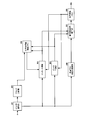
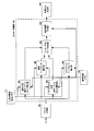
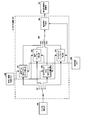
- FIG. 3 is a block diagram of a detailed configuration of an inter prediction unit 102 in FIG. 1.
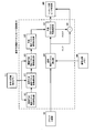
- FIG. FIG. 17 is a block diagram of a detailed configuration of a normal motion vector predictor mode deriving unit 301 in FIG. 16.
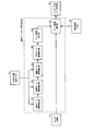
- FIG. 17 is a block diagram of a detailed configuration of a normal merge mode derivation unit 302 in FIG. 16.
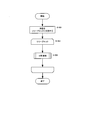
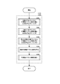
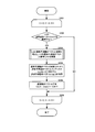
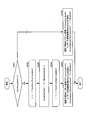
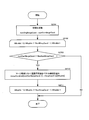
- 17 is a flowchart for explaining a normal motion vector predictor mode derivation process of the normal motion vector predictor mode deriving unit 301 in FIG. 16. It is a flow chart showing a processing procedure of normal prediction motion vector mode derivation processing. It is a flow chart explaining the processing procedure of normal merge mode derivation processing.
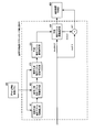
- 3 is a block diagram of a detailed configuration of an inter prediction unit 203 in FIG. 2.
- FIG. 23 is a block diagram of a detailed configuration of a normal motion vector predictor mode deriving unit 401 in FIG. 22.
- FIG. FIG. 23 is a block diagram of a detailed configuration of a normal merge mode derivation unit 402 in FIG. 22.
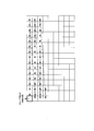
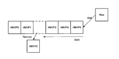
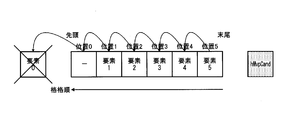
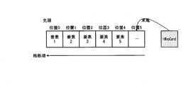
- 23 is a flowchart for explaining the normal motion vector predictor mode derivation process of the normal motion vector predictor mode deriving unit 401 in FIG. 22. It is a figure explaining a history motion vector predictor candidate list initialization and update processing procedure.
- 11 is a flowchart of the same element confirmation processing procedure in the history motion vector predictor candidate list initialization/update processing procedure.
- 11 is a flowchart of an element shift processing procedure in a history motion vector predictor candidate list initialization/update processing procedure.
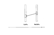
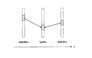
- Fig. 3 is a diagram for describing a prediction direction of motion-compensated prediction in the case of bi-prediction and a reference picture for L0 prediction and a reference picture for L1 prediction are at a time before a picture to be processed.
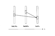
- Fig. 3 is a diagram for describing a prediction direction of motion compensation prediction in the case of bi-prediction and a reference picture for L0 prediction and a reference picture for L1 prediction are at a time later than a picture to be processed.
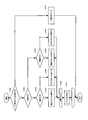
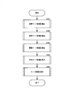
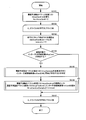
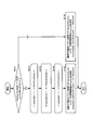
- 9 is a flowchart illustrating a procedure of a history motion vector predictor candidate derivation process in the case where the history motion vector predictor candidate list is used while referring to the order reverse to the storage order and the same candidate deletion process is not performed.
- 9 is a flowchart illustrating a procedure of a history motion vector predictor candidate derivation process in a case where the history motion vector predictor candidate list is used to perform the same candidate deletion process while referring to the order reverse to the storage order.
- the encoding/decoding processing target image is equally divided into a predetermined size.
- This unit is defined as a tree block.
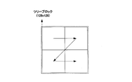
- the size of the tree block is 128 ⁇ 128 pixels in FIG. 4, the size of the tree block is not limited to this, and any size may be set.
- the tree blocks to be processed (corresponding to the encoding target in the encoding process and the decoding target in the decoding process) are switched in raster scan order, that is, from left to right and from top to bottom. The inside of each tree block can be further recursively divided.
- a block to be encoded/decoded after the tree block is recursively divided is defined as an encoded block.
- the tree block and the coding block are collectively defined as a block. Efficient encoding is possible by performing appropriate block division.
- the size of the tree block can be a fixed value pre-arranged by the encoding device and the decoding device, or the size of the tree block determined by the encoding device can be transmitted to the decoding device.
- the maximum size of the tree block is 128 ⁇ 128 pixels
- the minimum size of the tree block is 16 ⁇ 16 pixels.
- the maximum size of the coded block is 64x64 pixels
- the minimum size of the coded block is 4x4 pixels.
- Intra prediction that performs prediction from the processed image signal of the processing target image
- inter prediction MODE_INTER
- the processed image is used for an image obtained by decoding a signal that has been encoded in the encoding process, an image signal, a tree block, a block, an encoded block, etc., and an image, an image signal, for which the decoding has been completed in the decoding process. Used for tree blocks, blocks, coding blocks, etc.
- the prediction mode (PredMode) has intra prediction (MODE_INTRA) or inter prediction (MODE_INTER) as a value.
- L0 prediction is available for P slices.
- Pred_L0 L0 prediction
- Pred_L1 L1 prediction
- Pred_BI bi-prediction
- L0 prediction is inter prediction that refers to a reference picture managed by L0
- L1 prediction is inter prediction that refers to a reference picture managed by L1.
- Bi-prediction is inter prediction in which both L0 prediction and L1 prediction are performed and one reference picture managed by each of L0 and L1 is referred to.
- Information that specifies L0 prediction, L1 prediction, and bi-prediction is defined as an inter prediction mode. In the subsequent processing, it is premised that the processing is performed for each of L0 and L1 for the constants and variables with the subscript LX attached to the output.
- the motion vector predictor mode is a mode in which an index for specifying a motion vector predictor, a differential motion vector, an inter prediction mode, and a reference index are transmitted to determine inter prediction information of a block to be processed.
- the motion vector predictor includes a motion vector predictor candidate derived from a processed block adjacent to the process target block, or a block belonging to the processed image and located at the same position as the process target block or in the vicinity (neighboring) of the process target block, and the motion vector predictor. It is derived from the index for identifying the vector.
- the merge mode is a processed block that is adjacent to the processing target block without transmitting the differential motion vector or the reference index, or a block that belongs to the processed image and is located at the same position as the processing target block or in the vicinity thereof (nearby). This is a mode for deriving the inter prediction information of the processing target block from the inter prediction information of.
- the processed block adjacent to the block to be processed and the inter prediction information of the processed block as spatial merge candidates.
- a block that belongs to the processed image and is located at the same position as or near (the vicinity of) the block to be processed and the inter prediction information derived from the inter prediction information of the block are defined as temporal merge candidates.
- Each merge candidate is registered in the merge candidate list, and the merge index is used to identify the merge candidate used for prediction of the block to be processed.
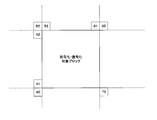
- FIG. 11 is a diagram illustrating reference blocks referred to in order to derive inter prediction information in the motion vector predictor mode and the merge mode.
- A0, A1, A2, B0, B1, B2, B3 are processed blocks adjacent to the processing target block.
- T0 is a block belonging to the processed image, which is located at the same position as the processing target block in the processing target image or in the vicinity (neighborhood) thereof.
- A1 and A2 are blocks located on the left side of the processing target coding block and adjacent to the processing target coding block.
- B1 and B3 are blocks located above the coding block to be processed and adjacent to the coding block to be processed.
- A0, B0, and B2 are blocks located at the lower left, upper right, and upper left of the process target coding block, respectively.
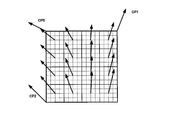
- Affine transform motion compensation is to perform motion compensation by dividing a coded block into sub-blocks of a predetermined unit and individually determining a motion vector for each of the divided sub-blocks.
- the motion vector of each sub-block is derived from inter prediction information of a processed block adjacent to the processing target block, or a block belonging to the processed image and located at the same position as the processing target block or in the vicinity (neighborhood) thereof 1 It derives based on one or more control points.
- the size of the sub block is 4 ⁇ 4 pixels, but the size of the sub block is not limited to this, and the motion vector may be derived in pixel units.
- FIG. 14 shows an example of affine transformation motion compensation when there are two control points.
- the two control points have two parameters, a horizontal component and a vertical component. Therefore, the affine transformation when there are two control points is called a four-parameter affine transformation.
- CP1 and CP2 in FIG. 14 are control points.
- FIG. 15 shows an example of affine transformation motion compensation when there are three control points. In this case, the three control points have two parameters, a horizontal component and a vertical component. Therefore, the affine transformation when there are three control points is called a 6-parameter affine transformation.
- CP1, CP2, and CP3 in FIG. 15 are control points.
- Affine transform motion compensation can be used in both the motion vector predictor mode and the merge mode.
- the mode in which the affine transform motion compensation is applied in the motion vector predictor mode is defined as the sub-block motion vector predictor mode
- the mode in which the affine transform motion compensation is applied in the merge mode is defined as the sub-block merge mode.
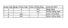
- the merge_flag in FIG. 12 is a flag indicating whether the process target coding block is in the merge mode or the motion vector predictor mode.
- merge_affine_flag is a flag indicating whether or not the sub-block merge mode is applied to the processing target coding block in the merge mode.
- inter_affine_flag is a flag indicating whether or not to apply the sub-block motion vector predictor mode in the processing target coding block of the motion vector predictor mode.
- cu_affine_type_flag is a flag for determining the number of control points in the sub-block motion vector predictor mode.
- FIG. 13 shows the value of each syntax element and the corresponding prediction method.
- the normal merge mode is a merge mode that is not a sub-block merge.
- the normal motion vector predictor mode is a motion vector predictor merge that is not the sub-block motion vector predictor mode.
- POC Picture Order Count
- POC Picture Order Count
- FIG. 1 is a block diagram of an image encoding device 100 according to the first embodiment.
- the image coding apparatus 100 includes a block division unit 101, an inter prediction unit 102, an intra prediction unit 103, a decoded image memory 104, a prediction method determination unit 105, a residual generation unit 106, an orthogonal transformation/quantization unit 107.
- the block dividing unit 101 recursively divides the input image to generate a coded block.
- the block division unit 101 includes a four division unit that divides a block to be divided into a horizontal direction and a vertical direction, and a 2-3 division unit that divides a block to be divided into either a horizontal direction or a vertical direction. Including.
- the block division unit 101 sets the generated coding block as a processing target coding block, and supplies the image signal of the processing target coding block to the inter prediction unit 102, the intra prediction unit 103, and the residual generation unit 106.
- the block division unit 101 also supplies information indicating the determined recursive division structure to the bit string encoding unit 108. The detailed operation of the block division unit 101 will be described later.
- the inter prediction unit 102 performs inter prediction of the coding block to be processed.
- the inter prediction unit 102 derives a plurality of inter prediction information candidates from the inter prediction information stored in the encoded information storage memory 111 and the decoded image signal stored in the decoded image memory 104, An appropriate inter prediction mode is selected from the derived plurality of candidates, and the selected inter prediction mode and the predicted image signal corresponding to the selected inter prediction mode are supplied to the prediction method determination unit 105.
- the detailed configuration and operation of the inter prediction unit 102 will be described later.
- the intra prediction unit 103 performs intra prediction of the process target coding block.
- the intra prediction unit 103 refers to the decoded image signal stored in the decoded image memory 104 as a reference pixel, and performs intra prediction based on the coding information such as the intra prediction mode stored in the coding information storage memory 111. To generate a predicted image signal.
- the intra prediction unit 103 selects a suitable intra prediction mode from a plurality of intra prediction modes, and predicts a selected intra prediction mode and a prediction image signal corresponding to the selected intra prediction mode. It is supplied to the determining unit 105.
- FIGS. 10A and 10B An example of intra prediction is shown in FIGS. 10A and 10B.
- FIG. 10A shows the correspondence between the prediction direction of intra prediction and the intra prediction mode number.
- the intra prediction mode 50 generates an intra prediction image by copying the reference pixel in the vertical direction.
- the intra prediction mode 1 is a DC mode in which all the pixel values of the processing target block are the average value of the reference pixels.
- Intra prediction mode 0 is a Planar mode, and is a mode in which a two-dimensional intra prediction image is created from reference pixels in the vertical and horizontal directions.
- FIG. 10B is an example of generating an intra prediction image in the case of the intra prediction mode 40.
- the intra prediction unit 103 copies the value of the reference pixel in the direction indicated by the intra prediction mode for each pixel of the processing target block. When the reference pixel in the intra prediction mode is not an integer position, the intra prediction unit 103 determines the reference pixel value by interpolation from the reference pixel values at the surrounding integer positions.
- the decoded image memory 104 stores the decoded image generated by the decoded image signal superimposing unit 110.
- the decoded image memory 104 supplies the stored decoded image to the inter prediction unit 102 and the intra prediction unit 103.
- the prediction method determination unit 105 evaluates each of the intra prediction and the inter prediction by using the coding amount of the coding information and the residual, the distortion amount between the predicted image signal and the processing target image signal, and the like. , Determine the optimal prediction mode.
- the prediction method determination unit 105 supplies intra prediction information such as the intra prediction mode to the bit string coding unit 108 as coding information.
- the prediction method determination unit 105 uses the inter-prediction information such as the merge index and information (sub-block merge flag) indicating whether or not the sub-block merge mode is the bit string encoding unit 108 as the encoding information. Supply to.
- the prediction method determination unit 105 is information indicating whether the inter prediction mode, the motion vector predictor index, the reference indexes of L0 and L1, the differential motion vector, and the sub block motion vector predictor mode. Inter prediction information such as (sub-block motion vector predictor flag) is supplied to the bit string coding unit 108 as coding information. Furthermore, the prediction method determination unit 105 supplies the determined coding information to the coding information storage memory 111. The prediction method determination unit 105 supplies the residual error generation unit 106 and the predicted image signal to the decoded image signal superposition unit 110.
- the residual generation unit 106 generates a residual by subtracting the predicted image signal from the image signal to be processed, and supplies the residual to the orthogonal transformation/quantization unit 107.
- the orthogonal transformation/quantization unit 107 performs orthogonal transformation and quantization on the residual according to the quantization parameter to generate an orthogonal transformation/quantized residual, and the generated residual is the bit string encoding unit 108. And the inverse quantization/inverse orthogonal transformation unit 109.
- the bit string coding unit 108 codes coding information according to the prediction method determined by the prediction method determination unit 105 for each coding block, in addition to information on a sequence, picture, slice, and coding block unit. Specifically, the bit string coding unit 108 codes the prediction mode PredMode for each coding block.
- the bit string encoding unit 108 determines whether or not the mode is the merge mode, the sub-block merge flag, the merge index in the case of the merge mode, the inter prediction mode in the case of not the merge mode, Coding information (inter prediction information) such as a motion vector predictor index, information about a differential motion vector, and a sub-block motion vector predictor flag is coded according to a prescribed syntax (syntax rule of bit string) to generate a first bit string.
- the prediction mode is intra prediction (MODE_INTRA)
- the coding information intra prediction information
- intra prediction mode is coded according to the prescribed syntax (bit string syntax rule) to generate the first bit string.
- bit string encoding unit 108 entropy-encodes the orthogonally transformed and quantized residual according to a prescribed syntax to generate a second bit string.
- the bit string encoding unit 108 multiplexes the first bit string and the second bit string according to a prescribed syntax and outputs a bit stream.
- the inverse quantization/inverse orthogonal transformation unit 109 performs inverse quantization and inverse orthogonal transformation on the orthogonal transformation/quantized residual supplied from the orthogonal transformation/quantization unit 107 to calculate the residual, and the calculated residual. The difference is supplied to the decoded image signal superimposing unit 110.
- the decoded image signal superimposing unit 110 superimposes the prediction image signal according to the determination made by the prediction method determining unit 105 and the residuals that have been inversely quantized and inversely orthogonally transformed by the inverse quantization/inverse orthogonal transformation unit 109 to obtain a decoded image. It is generated and stored in the decoded image memory 104. Note that the decoded image signal superimposing unit 110 may store the decoded image in the decoded image memory 104 after performing a filtering process on the decoded image to reduce distortion such as block distortion due to encoding.
- the coding information storage memory 111 stores the coding information such as the prediction mode (inter prediction or intra prediction) determined by the prediction method determination unit 105.
- the coding information stored in the coding information storage memory 111 includes inter prediction information such as the determined motion vector, the reference index of the reference lists L0 and L1, the history prediction motion vector candidate list, and the like.
- the coding information stored in the coding information storage memory 111 includes, in addition to the above-described information, information indicating whether or not the merge index and the sub block merge mode (sub block merge flag). ) Inter prediction information is included.
- the coding information stored in the coding information storage memory 111 includes the inter prediction mode, the motion vector predictor index, the difference motion vector, and the sub block prediction in addition to the above-mentioned information.
- Inter prediction information such as information (sub-block prediction motion vector flag) indicating whether or not the motion vector mode is included.
- the coding information stored in the coding information storage memory 111 includes intra prediction information such as the determined intra prediction mode.
- FIG. 2 is a block diagram showing a configuration of an image decoding device according to an embodiment of the present invention, which corresponds to the image encoding device of FIG.
- the image decoding apparatus includes a bit string decoding unit 201, a block dividing unit 202, an inter prediction unit 203, an intra prediction unit 204, an encoded information storage memory 205, an inverse quantization/inverse orthogonal transform unit 206, and a decoded image signal superimposition.
- a unit 207 and a decoded image memory 208 are provided.
- the decoding process of the image decoding device in FIG. 2 corresponds to the decoding process provided inside the image coding device in FIG. 1, so the coding information storage memory 205 in FIG.
- the configurations of the orthogonal transformation unit 206, the decoded image signal superimposing unit 207, and the decoded image memory 208 are as follows: the coding information storage memory 111, the inverse quantization/inverse orthogonal transformation unit 109, and the decoded image signal of the image encoding device in FIG. It has a function corresponding to each configuration of the superimposing unit 110 and the decoded image memory 104.
- the bit stream supplied to the bit string decoding unit 201 is separated in accordance with the prescribed syntax rule.
- the bit string decoding unit 201 decodes the separated first bit string to obtain a sequence, a picture, a slice, information in units of coding blocks, and coding information in units of coding blocks. Specifically, the bit string decoding unit 201 decodes the prediction mode PredMode that determines whether the prediction is inter prediction (MODE_INTER) or intra prediction (MODE_INTRA) for each coding block.
- PredMode that determines whether the prediction is inter prediction (MODE_INTER) or intra prediction (MODE_INTRA) for each coding block.
- the bit string decoding unit 201 determines a flag for determining whether the mode is the merge mode, a merge index in the merge mode, a sub-block merge flag, and an inter prediction in the motion vector predictor mode.
- the coding information (inter prediction information) about the mode, the motion vector predictor index, the difference motion vector, the sub-block motion vector predictor flag, etc. is decoded according to the prescribed syntax, and the coding information (inter prediction information) is inter-prediction unit 203, And to the encoded information storage memory 205 via the block division unit 202.
- the prediction mode is intra prediction (MODE_INTRA)
- the coding information (intra prediction information) such as the intra prediction mode is decoded according to the prescribed syntax, and the coding information (intra prediction information) is decoded into the inter prediction unit 203 or the intra prediction unit. It is supplied to the coded information storage memory 205 via the block 204 and the block division unit 202.
- the bit string decoding unit 201 decodes the separated second bit string to calculate an orthogonally transformed/quantized residual, and supplies the orthogonally transformed/quantized residual to the inverse quantization/inverse orthogonal transforming unit 206. To do.
- the inter prediction unit 203 when the prediction mode PredMode of the coding block to be processed is inter prediction (MODE_INTER) and is the motion vector predictor mode, codes the already decoded image signal stored in the coding information storage memory 205.
- a plurality of motion vector predictor candidates are derived using the conversion information, and the derived plurality of motion vector predictor candidates are registered in a motion vector predictor candidate list to be described later.
- the inter prediction unit 203 selects, from among the plurality of motion vector predictor candidates registered in the motion vector predictor candidate list, a motion vector predictor according to the motion vector predictor index decoded and supplied by the bit string decoding unit 201, A motion vector is calculated from the differential motion vector decoded by the bit string decoding unit 201 and the selected motion vector predictor, and the calculated motion vector is stored in the coding information storage memory 205 together with other coding information.
- the coding information of the coding block supplied/stored here is a flag predFlagL0[xP][yP], predFlagL1[xP][yP], which indicates whether or not to use the prediction modes PredMode, L0 prediction, and L1 prediction.
- xP and yP are indexes indicating the position of the upper left pixel of the encoded block in the picture.
- PredMode is inter prediction (MODE_INTER) and the inter prediction mode is L0 prediction (Pred_L0)
- the flag predFlagL0 that indicates whether to use L0 prediction is 1, and the flag predFlagL1 that indicates whether to use L1 prediction Is 0.
- the flag predFlagL0 indicating whether to use L0 prediction is 0, and the flag predFlagL1 indicating whether to use L1 prediction is 1.
- the inter prediction mode is bi-prediction (Pred_BI)
- both the flag predFlagL0 indicating whether to use L0 prediction and the flag predFlagL1 indicating whether to use L1 prediction are 1.
- the prediction mode PredMode of the coding block to be processed is inter prediction (MODE_INTER) and the merge mode, a merge candidate is derived.
- a plurality of merge candidates are derived and registered in the merge candidate list described later, and registered in the merge candidate list.
- xP and yP are indexes indicating the position of the upper left pixel of the encoded block in the picture.
- the intra prediction unit 204 performs intra prediction when the prediction mode PredMode of the target coding block is intra prediction (MODE_INTRA).
- the coded information decoded by the bit string decoding unit 201 includes the intra prediction mode.
- the intra prediction unit 204 generates a predicted image signal by intra prediction from the decoded image signal stored in the decoded image memory 208 according to the intra prediction mode included in the encoded information decoded by the bit string decoding unit 201. Then, the generated predicted image signal is supplied to the decoded image signal superimposing unit 207.
- the intra prediction unit 204 corresponds to the intra prediction unit 103 of the image encoding device 100, and therefore performs the same process as the intra prediction unit 103.
- the inverse quantization/inverse orthogonal transformation unit 206 performs inverse orthogonal transformation and inverse quantization on the orthogonal transformation/quantized residual decoded by the bit string decoding unit 201, and is subjected to inverse orthogonal transformation/inverse quantization. Get the residuals.
- the decoded image signal superimposing unit 207 and the predictive image signal inter-predicted by the inter predicting unit 203 or the predictive image signal intra-predicted by the intra predicting unit 204, and the inverse orthogonal transform/inverse orthogonal transform unit 206 perform the inverse orthogonal transform/inverse orthogonal transform.
- the decoded image signal is decoded by superimposing the dequantized residual, and the decoded decoded image signal is stored in the decoded image memory 208.
- the decoded image signal superimposing unit 207 may perform filtering processing on the decoded image to reduce block distortion due to encoding, and then store the decoded image signal in the decoded image memory 208. ..
- FIG. 3 is a flowchart showing an operation of dividing an image into tree blocks and further dividing each tree block.
- the input image is divided into tree blocks of a predetermined size (step S1001).
- Each tree block is scanned in a predetermined order, that is, in raster scan order (step S1002), and the inside of the tree block to be processed is divided (step S1003).
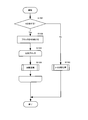
- FIG. 7 is a flowchart showing the detailed operation of the division processing in step S1003. First, it is determined whether or not the block to be processed is divided into four (step S1101).
- the processing target block is divided into four (step S1102).
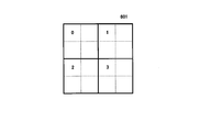
- Each block obtained by dividing the block to be processed is scanned in the Z scan order, that is, in the order of upper left, upper right, lower left, and lower right (step S1103).
- FIG. 5 is an example of the Z scan order
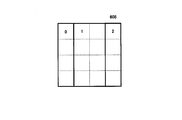
- 601 of FIG. 6A is an example in which the processing target block is divided into four.
- the numbers 0 to 3 in 601 of FIG. 6A indicate the order of processing.
- the division processing of FIG. 7 is recursively executed (step S1104).
- step S1105) If it is determined that the block to be processed is not divided into four, 2-3 division is performed (step S1105).
- FIG. 8 is a flowchart showing the detailed operation of the 2-3 division process of step S1105. First, it is determined whether or not the block to be processed is divided into 2-3, that is, whether to divide into 2 or 3 (step S1201).
- step S1211 the division is ended (step S1211).
- the block divided by the recursive division process is not further recursively divided.
- step S1202 it is further determined whether or not the block to be processed is further divided into two.
- step S1203 it is determined whether or not the processing target block is divided into upper and lower parts (vertical direction) (step S1203), and based on the result, the processing target block is vertically (vertical direction) divided.
- the block to be processed is divided into two (step S1204) or the block to be processed is divided into left and right (horizontal direction) into two (step S1205).
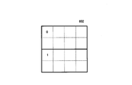
- step S1204 the processing target block is divided into upper and lower (vertical direction) halves as indicated by 602 in FIG. 6B.
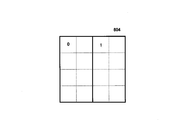
- step S1205 the processing target block is left and right (horizontal) as shown in 604 of FIG. 6D. Direction) divided into two.
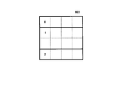
- step S1202 If it is not determined in step S1202 that the block to be processed is divided into two, that is, if it is determined that the block is to be divided into three, it is determined whether the block to be processed is divided into upper, middle, and lower (vertical direction) (step S1206). ), based on the result, the block to be processed is divided into upper, middle and lower (vertical direction) into three (step S1207), or the block to be processed is divided into left, middle and right (horizontal direction) into three (step S1208). As a result of step S1207, the processing target block is divided into upper, middle, lower (vertical direction) three divisions as shown by 603 in FIG. 6C, and as a result of step S1208, the processing target block is left as shown by 605 in FIG. 6E. Middle right (horizontal direction) divided into three.
- step S1209 After executing any of step S1204, step S1205, step S1207, and step S1208, each block obtained by dividing the block to be processed is scanned from left to right and from top to bottom (step S1209).
- the numbers 0 to 2 of 602 to 605 in FIGS. 6B to 6E indicate the order of processing.
- the 2-3 division process of FIG. 8 is recursively executed (step S1210).
- the necessity of division may be limited depending on the number of divisions or the size of the block to be processed.
- the information that restricts the necessity of division may be realized in a configuration in which information is not transmitted by making an agreement in advance between the encoding device and the decoding device, or the encoding device limits the necessity of division. It may be realized by a configuration in which the information to be determined is recorded and recorded in a bit string and transmitted to the decoding device.
- each block after the division is called the child block.
- the block division unit 202 divides a tree block by the same processing procedure as the block division unit 101 of the image encoding device 100.
- the block division unit 101 of the image coding apparatus 100 applies an optimization method such as estimation of an optimum shape by image recognition or optimization of a distortion rate to determine the optimum shape of block division, whereas the image decoding apparatus
- the block division unit 202 in 200 is different in that the block division shape is determined by decoding the block division information recorded in the bit string.
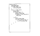
- FIG. 9 shows the syntax (syntax rule of bit string) regarding the block division of the first embodiment.
- coding_quadtree() represents the syntax for block quadrant processing.
- multi_type_tree() represents the syntax for the block division or division into three.
- each block divided into 4 is recursively divided into 4 (coding_quadtree(0), coding_quadtree(1), coding_quadtree(2), coding_quadtree(3), 0 to argument 3 corresponds to the number 601 in FIG. 6A).
- mtt_split is a flag indicating whether or not to further divide.
- mtt_split_vertical that is a flag indicating whether to divide vertically or horizontally
- mtt_split_binary that is a flag that determines whether to divide into two or three are transmitted.
- each divided block is subjected to recursive division processing (multi_type_tree(0), multi_type_tree(1), 0 to 1 of arguments are 602 or 604 of FIGS. 6B to D. Corresponds to the number.).
- multi_type_tree(0), multi_type_tree(1), multi_type_tree(2), 0 to 2 are 603 in FIG. It corresponds to the number 605 of 6E.).
- the inter prediction method according to the embodiment is implemented in the inter prediction unit 102 of the image coding apparatus of FIG. 1 and the inter prediction unit 203 of the image decoding apparatus of FIG.
- the inter prediction method according to the embodiment will be described with reference to the drawings.
- the inter-prediction method is carried out in both coding and decoding processing in coding block units.
- FIG. 16 is a diagram showing a detailed configuration of the inter prediction unit 102 of the image coding apparatus in FIG.
- the normal motion vector predictor mode deriving unit 301 derives a plurality of normal motion vector predictor candidates, selects a motion vector predictor, and calculates a difference motion vector between the selected motion vector predictor and the detected motion vector.
- the detected inter prediction mode, reference index, motion vector, and calculated differential motion vector serve as inter prediction information in the normal motion vector predictor mode. This inter prediction information is supplied to the inter prediction mode determination unit 305.
- the detailed configuration and processing of the normal motion vector predictor mode deriving unit 301 will be described later.
- the normal merge mode deriving unit 302 derives a plurality of normal merge candidates, selects a normal merge candidate, and obtains inter prediction information of the normal merge mode. This inter prediction information is supplied to the inter prediction mode determination unit 305. The detailed configuration and processing of the normal merge mode derivation unit 302 will be described later.
- the sub-block motion vector predictor mode deriving unit 303 derives a plurality of sub-block motion vector predictor candidates, selects a sub-block motion vector predictor, and calculates a difference motion vector between the selected sub-block motion vector predictor and the detected motion vector. calculate.
- the detected inter prediction mode, reference index, motion vector, and calculated differential motion vector serve as inter prediction information in the sub-block prediction motion vector mode. This inter prediction information is supplied to the inter prediction mode determination unit 305.
- the sub-block merge mode deriving unit 304 derives a plurality of sub-block merge candidates, selects a sub-block merge candidate, and obtains inter prediction information in the sub-block merge mode. This inter prediction information is supplied to the inter prediction mode determination unit 305.
- the inter prediction mode determination unit 305 is based on the inter prediction information supplied from the normal motion vector predictor mode derivation unit 301, the normal merge mode derivation unit 302, the sub block motion vector predictor mode derivation unit 303, and the sub block merge mode derivation unit 304. , Inter prediction information is determined.
- the inter prediction mode determination unit 305 supplies inter prediction information according to the determination result to the motion compensation prediction unit 306.
- the motion compensation prediction unit 306 performs inter prediction on the reference image signal stored in the decoded image memory 104 based on the determined inter prediction information. The detailed configuration and processing of the motion compensation prediction unit 306 will be described later.
- ⁇ Description of Inter Prediction Unit 203 on Decoding Side> 22 is a diagram showing a detailed configuration of the inter prediction unit 203 of the image decoding apparatus in FIG.
- the normal motion vector predictor mode deriving unit 401 derives a plurality of normal motion vector predictor candidates, selects a motion vector predictor, and calculates an addition value of the selected motion vector predictor and the decoded differential motion vector to obtain a motion vector. To do.
- the decoded inter prediction mode, reference index, and motion vector serve as inter prediction information in the normal motion vector predictor mode. This inter prediction information is supplied to the motion compensation prediction unit 406 via the switch 408. The detailed configuration and processing of the normal motion vector predictor mode deriving unit 401 will be described later.
- the normal merge mode derivation unit 402 derives a plurality of normal merge candidates, selects a normal merge candidate, and obtains inter prediction information in the normal merge mode. This inter prediction information is supplied to the motion compensation prediction unit 406 via the switch 408. The detailed configuration and processing of the normal merge mode derivation unit 402 will be described later.
- the sub-block motion vector predictor mode deriving unit 403 derives a plurality of sub-block motion vector predictor candidates, selects a sub-block motion vector predictor, and calculates the sum of the selected sub-block motion vector predictor and the decoded differential motion vector. It is calculated and used as a motion vector.
- the decoded inter prediction mode, reference index, and motion vector serve as inter prediction information in the sub-block prediction motion vector mode. This inter prediction information is supplied to the motion compensation prediction unit 406 via the switch 408.
- the sub-block merge mode deriving unit 404 derives a plurality of sub-block merge candidates, selects a sub-block merge candidate, and obtains inter prediction information in the sub-block merge mode. This inter prediction information is supplied to the motion compensation prediction unit 406 via the switch 408.
- the motion compensation prediction unit 406 performs inter prediction on the reference image signal stored in the decoded image memory 208 based on the determined inter prediction information.
- the detailed configuration and processing of the motion compensation prediction unit 406 are the same as those of the motion compensation prediction unit 306 on the encoding side.
- the normal motion vector predictor mode derivation unit 301 in FIG. 17 includes a spatial motion vector predictor candidate derivation unit 321, a temporal motion vector predictor candidate derivation unit 322, a history motion vector predictor candidate derivation unit 323, a motion vector predictor candidate supplementation unit 325, and a normal motion.
- the vector detection unit 326, the motion vector predictor candidate selection unit 327, and the motion vector subtraction unit 328 are included.
- the normal motion vector predictor mode derivation unit 401 in FIG. 23 includes a spatial motion vector predictor candidate derivation unit 421, a temporal motion vector predictor candidate derivation unit 422, a history motion vector predictor candidate derivation unit 423, a motion vector predictor candidate replenishment unit 425, and a motion predictive motion.
- a vector candidate selection unit 426 and a motion vector addition unit 427 are included.
- FIG. 19 is a flowchart showing the procedure of the normal motion vector predictor mode deriving processing by the normal motion vector mode deriving section 301 on the encoding side
- FIG. 25 is the normal motion vector predictor mode deriving processing by the normal motion vector mode deriving section 401 on the decoding side. It is a flowchart which shows a procedure.
- Normal motion vector predictor (normal AMVP): Description of coding side> The normal motion vector predictor mode derivation process procedure on the encoding side will be described with reference to FIG. In the description of the processing procedure of FIG. 19, the word “normal” shown in FIG. 19 may be omitted.
- the normal motion vector detection unit 326 detects a normal motion vector for each inter prediction mode and reference index (step S100 in FIG. 19).
- the differential motion vector of the motion vector used in the inter prediction in the normal motion vector predictor mode is calculated for each of L0 and L1 (steps S101 to S106 in FIG. 19).
- the prediction mode PredMode of the target block is inter prediction (MODE_INTER) and the inter prediction mode is L0 prediction (Pred_L0)
- the motion vector predictor candidate list mvpListL0 of L0 is calculated and the motion vector predictor mvpL0 is selected.
- the differential motion vector mvdL0 of the motion vector mvL0 of L0 is calculated.
- the inter prediction mode of the block to be processed is L1 prediction (Pred_L1)
- the motion vector predictor candidate list mvpListL1 of L1 is calculated, the motion vector predictor mvpL1 is selected, and the differential motion vector mvdL1 of the motion vector mvL1 of L1 is calculated. ..
- both L0 prediction and L1 prediction are performed, a motion vector predictor candidate list mvpListL0 of L0 is calculated, and a motion vector predictor mvpL0 of L0 is selected, and L0 is calculated.
- Motion vector mvL0 differential motion vector mvdL0 is calculated, L1 motion vector predictor candidate list mvpListL1 is calculated, L1 motion vector predictor mvpL1 is calculated, and L1 motion vector mvL1 differential motion vector mvdL1 is calculated. To do.
- L0 and L1 are represented as common LX.
- the X of LX is 0, and in the process of calculating the differential motion vector of L1, the X of LX is 1.
- the other list is represented as LY.
- the motion vector predictor candidate of LX is calculated and the motion vector predictor candidate list mvpListLX of LX is constructed (step S103 of FIG. 19).
- the spatial motion vector predictor candidate deriving unit 321, the temporal motion vector predictor candidate deriving unit 322, the history motion vector predictor candidate deriving unit 323, and the motion vector predictor candidate replenishing unit 325 include a plurality of motion predictive motions.
- the motion vector candidate list mvpListLX is constructed by deriving vector candidates.
- the motion vector predictor candidate selection unit 327 selects the motion vector predictor mvpLX of LX from the motion vector predictor candidate list of LX mvpListLX (step S104 in FIG. 19).
- the motion vector predictor candidate list mvpListLX one certain element (i-th element counting from 0) is represented as mvpListLX[i].
- Each difference motion vector that is the difference between the motion vector mvLX and each motion vector predictor candidate mvpListLX[i] stored in the motion vector predictor candidate list mvpListLX is calculated.
- a code amount when the difference motion vectors are encoded is calculated for each element (predictive motion vector candidate) of the motion vector predictor candidate list mvpListLX. Then, among the elements registered in the motion vector predictor candidate list mvpListLX, the motion vector predictor candidate mvpListLX[i] that minimizes the code amount for each motion vector predictor candidate is selected as the motion vector predictor mvpLX, and Get the index i.
- the motion vector predictor represented by a smaller index i in the motion vector predictor candidate list mvpListLX When there are a plurality of motion vector predictor candidates having the smallest amount of generated code in the motion vector predictor candidate list mvpListLX, the motion vector predictor represented by a smaller index i in the motion vector predictor candidate list mvpListLX.
- the candidate mvpListLX[i] of is selected as the optimum motion vector predictor mvpLX and its index i is acquired.
- Normal motion vector predictor (normal AMVP): Description of decoding side>
- the normal motion vector predictor mode processing procedure on the decoding side will be described with reference to FIG.
- the spatial motion vector predictor candidate derivation unit 421, the temporal motion vector predictor candidate derivation unit 422, the history motion vector predictor candidate derivation unit 423, and the motion vector predictor candidate supplementation unit 425 are used in inter prediction in the normal motion vector predictor mode.
- the motion vector is calculated for each of L0 and L1 (steps S201 to S206 in FIG. 25).
- the prediction motion vector candidate list mvpListL0 of L0 is calculated, and the prediction motion is calculated.
- the vector mvpL0 is selected and the motion vector mvL0 of L0 is calculated.
- the inter prediction mode of the block to be processed is L1 prediction (Pred_L1)
- the motion vector predictor candidate list mvpListL1 for L1 is calculated, the motion vector predictor mvpL1 is selected, and the motion vector mvL1 for L1 is calculated.
- both L0 prediction and L1 prediction are performed, a motion vector predictor candidate list mvpListL0 of L0 is calculated, and a motion vector predictor mvpL0 of L0 is selected and L0 is calculated.
- Motion vector mvL0 of L1 the motion vector predictor candidate list mvpListL1 of L1 is calculated, the motion vector predictor mvpL1 of L1 is calculated, and the motion vector mvL1 of L1 is calculated.
- L0 and L1 are represented as common LX.
- LX represents an inter prediction mode used for inter prediction of a coding block to be processed.
- X is 0 in the process of calculating the motion vector of L0, and X is 1 in the process of calculating the motion vector of L1.
- the other reference list is expressed as LY.
- the motion vector predictor candidate of LX is calculated to construct the motion vector predictor candidate list mvpListLX of LX (step S203 of FIG. 25).
- the spatial motion vector predictor candidate deriving unit 421, the temporal motion vector predictor candidate deriving unit 422, the history motion vector predictor candidate deriving unit 423, and the motion vector predictor candidate replenishing unit 425 include a plurality of motion predictive motions.
- Vector candidates are calculated and a motion vector predictor candidate list mvpListLX is constructed.
- the motion vector predictor candidate selection unit 426 selects a motion vector predictor candidate mvpListLX[mvpIdxLX] corresponding to the motion vector predictor index mvpIdxLX decoded and supplied from the motion vector predictor candidate list mvpListLX by the bit string decoding unit 201.
- the predicted motion vector mvpLX thus obtained is extracted (step S204 in FIG. 25).
- the motion vector mvLX of LX is calculated as (step S205 in FIG. 25).
- FIG. 20 is a normal motion vector predictor mode derivation having a common function with the normal motion vector predictor mode deriving unit 301 of the image encoding device and the normal motion vector predictor mode deriving unit 401 of the image decoding device according to the embodiment of the present invention. It is a flow chart showing a processing procedure of processing.
- the normal motion vector predictor mode deriving unit 301 and the normal motion vector predictor mode deriving unit 401 include a motion vector predictor candidate list mvpListLX.
- the motion vector predictor candidate list mvpListLX has a list structure, and is provided with a storage area for storing, as elements, a motion vector predictor vector index indicating a location in the motion vector predictor candidate list and a motion vector predictor candidate corresponding to the index. ..
- the number of the motion vector predictor index starts from 0, and the motion vector predictor candidates are stored in the storage area of the motion vector predictor candidate list mvpListLX.
- 0 is set to a variable numCurrMvpCand indicating the number of motion vector predictor candidates registered in the motion vector predictor candidate list mvpListLX.
- the spatial motion vector predictor candidate derivation units 321 and 421 derive motion vector predictor candidates from the block adjacent to the left side.
- the inter prediction information of the block adjacent to the left side A0 or A1 in FIG. 11
- a flag indicating whether or not the motion vector predictor candidate is available, and the motion vector, the reference index, etc. are referred to
- the vector mvLXA is derived, and the derived mvLXA is added to the motion vector predictor candidate list mvpListLX (step S301 in FIG. 20). Note that X is 0 for L0 prediction and X is 1 for L1 prediction (the same applies hereinafter).
- the spatial motion vector predictor candidate derivation units 321 and 421 derive motion vector predictor candidates from blocks adjacent to the upper side.
- the inter prediction information of the block (B0, B1, or B2 in FIG. 11) adjacent to the upper side that is, a flag indicating whether or not the motion vector predictor candidate can be used, the motion vector, the reference index, and the like are referred to.
- the motion vector predictor mvLXB is derived, and if the derived mvLXA and mvLXB are not equal, mvLXB is added to the motion vector predictor candidate list mvpListLX (step S302 in FIG. 20).
- a reference index refIdxN (N indicates A or B, and so on).
- the temporal motion vector predictor candidate derivation units 322 and 422 derive motion vector predictor candidates from blocks in a picture whose time is different from that of the current picture to be processed.
- a flag availableFlagLXCol indicating whether or not a motion vector predictor candidate of a coded block of a picture at a different time is available
- a motion vector mvLXCol, a reference index refIdxCol, and a reference list listCol are derived
- mvLXCol is a motion vector predictor candidate. It is added to the list mvpListLX (step S303 in FIG. 20).
- temporal motion vector predictor candidate derivation units 322 and 422 can be omitted for each sequence (SPS), picture (PPS), or slice unit.
- the historical motion vector predictor candidate derivation units 323 and 423 add the historical motion vector predictor candidates registered in the historical motion vector predictor list HmvpCandList to the motion vector predictor candidate list mvpListLX. (Step S304 of FIG. 20). Details of the registration processing procedure in step S304 will be described later with reference to the flowchart in FIG.
- the motion vector predictor candidate supplementing units 325 and 425 add motion vector predictor candidates having a predetermined value such as (0, 0) until the motion vector predictor candidate list mvpListLX is satisfied (S305 in FIG. 20).
- the normal merge mode derivation unit 302 in FIG. 18 includes a spatial merge candidate derivation unit 341, a temporal merge candidate derivation unit 342, an average merge candidate derivation unit 344, a history merge candidate derivation unit 345, a merge candidate replenishment unit 346, and a merge candidate selection unit 347. including.
- the normal merge mode derivation unit 402 of FIG. 24 includes a spatial merge candidate derivation unit 441, a temporal merge candidate derivation unit 442, an average merge candidate derivation unit 444, a history merge candidate derivation unit 445, a merge candidate replenishment unit 446, and a merge candidate selection unit 447. including.
- FIG. 21 illustrates a procedure of a normal merge mode derivation process having a common function with the normal merge mode derivation unit 302 of the image encoding device and the normal merge mode derivation unit 402 of the image decoding device according to the embodiment of the present invention. It is a flowchart.
- the normal merge mode derivation unit 302 and the normal merge mode derivation unit 402 include a merge candidate list mergeCandList.
- the merge candidate list mergeCandList has a list structure, and is provided with a merge index indicating the location inside the merge candidate list and a storage area for storing merge candidates corresponding to the index as elements. The number of the merge index starts from 0, and the merge candidate is stored in the storage area of the merge candidate list mergeCandList.
- the merge candidates of the merge index i registered in the merge candidate list mergeCandList will be represented by mergeCandList[i].
- the merge candidate list mergeCandList can register at least 6 merge candidates (inter prediction information). Further, 0 is set to the variable numCurrMergeCand indicating the number of merge candidates registered in the merge candidate list mergeCandList.
- the block to be processed is processed from the coding information stored in the coding information storage memory 111 of the image coding device or the coding information storage memory 205 of the image decoding device.
- Spatial merge candidates from blocks (B1, A1, B0, A0, B2 in FIG. 11) adjacent to the left side and the upper side of B1 are derived in the order of B1, A1, B0, A0, B2, and the derived spatial merge is obtained.
- the candidates are registered in the merge candidate list mergeCandList (step S401 in FIG. 21).
- N indicating any of the spatial merge candidates B1, A1, B0, A0, B2 or the temporal merge candidate Col is defined.
- the flag predFlagL0N and the L1 prediction flag predFlagL1N and the motion vector mvL0N of L0 and the motion vector mvL1N of L1 which show whether L1 prediction are performed are derived.
- the merge candidate is derived without referring to the inter prediction information of the block included in the coding block to be processed
- the inter prediction information of the block included in the coding block to be processed is derived.
- a spatial merge candidate using is not derived.
- the temporal merge candidate derivation unit 342 and the temporal merge candidate derivation unit 442 derive temporal merge candidates from pictures at different times and register the derived temporal merge candidates in the merge candidate list mergeCandList (FIG. 21).
- Step S402 A flag availableFlagCol indicating whether or not the temporal merge candidate is available, an L0 prediction flag predFlagL0Col indicating whether or not L0 prediction of the temporal merge candidate is performed and an L1 prediction flag predFlagL1Col and L0 indicating whether or not L1 prediction is performed.
- the motion vector mvL0Col of L1 and the motion vector mvL1Col of L1 are derived.
- the processes of the temporal merge candidate derivation unit 342 and the temporal merge candidate derivation unit 442 can be omitted for each sequence (SPS), picture (PPS), or slice.
- the history merge candidate derivation unit 345 and the history merge candidate derivation unit 445 register the history motion vector predictor candidates registered in the history motion vector predictor candidate list HmvpCandList in the merge candidate list mergeCandList (step S403 in FIG. 21). .. If the number of merge candidates numCurrMergeCand registered in the merge candidate list mergeCandList is smaller than the maximum number of merge candidates MaxNumMergeCand, the number of merge candidates numCurrMergeCand registered in the merge candidate list mergeCandList is the maximum number of merge candidates MaxNumMergeCand as the upper limit.
- the history merge candidate is derived and registered in the merge candidate list mergeCandList.
- the average merge candidate derivation unit 344 and the average merge candidate derivation unit 444 derive the average merge candidate from the merge candidate list mergeCandList and add the derived average merge candidate to the merge candidate list mergeCandList (step in FIG. 21). S404). If the number of merge candidates numCurrMergeCand registered in the merge candidate list mergeCandList is smaller than the maximum number of merge candidates MaxNumMergeCand, the number of merge candidates numCurrMergeCand registered in the merge candidate list mergeCandList is the maximum number of merge candidates MaxNumMergeCand as the upper limit.
- the average merge candidate is derived and registered in the merge candidate list mergeCandList.
- the average merge candidate has a new motion vector obtained by averaging the motion vectors of the first merge candidate and the second merge candidate registered in the merge candidate list mergeCandList for each L0 prediction and L1 prediction. It is a good candidate for merging.
- the merge candidate supplementing unit 346 and the merge candidate supplementing unit 446 when the number of merge candidates numCurrMergeCand registered in the merge candidate list mergeCandList is smaller than the maximum number of merge candidates MaxNumMergeCand, it is registered in the merge candidate list mergeCandList.
- the number of merge candidates numCurrMergeCand that is present derives additional merge candidates with the maximum number of merge candidates MaxNumMergeCand as the upper limit, and registers them in the merge candidate list mergeCandList (step S405 in FIG. 21).
- a merge candidate whose motion vector has a value of (0, 0) and whose prediction mode is L0 prediction (Pred_L0) is added.
- a merge candidate in which the prediction mode in which the motion vector has a value of (0,0) is bi-prediction (Pred_BI) is added.
- the reference index when adding a merge candidate is different from the reference index already added.
- the merge candidate selection unit 347 and the merge candidate selection unit 447 select merge candidates from the merge candidates registered in the merge candidate list mergeCandList.
- the merging candidate selecting unit 347 on the encoding side selects the merging candidate by calculating the code amount and the distortion amount, and selects the merging index indicating the merging candidate selected, the inter prediction information of the merging candidate, and the inter prediction mode judging unit. It is supplied to the motion compensation prediction unit 306 via 305.
- the merge candidate selection unit 447 on the decoding side selects a merge candidate based on the decoded merge index and supplies the selected merge candidate to the motion compensation prediction unit 406.
- FIG. 26 is a flowchart for explaining the procedure of the process of initializing and updating the history motion vector predictor candidate list.
- history motion vector predictor candidate list HmvpCandList is updated in the encoded information storage memory 111 and the encoded information storage memory 205.
- a history motion vector predictor candidate list update unit may be installed in the inter prediction unit 102 and the inter prediction unit 203 to update the history motion vector predictor candidate list HmvpCandList.
- the history motion vector predictor candidate list HmvpCandList is initialized at the beginning of the slice, and when the normal motion vector predictor mode or the normal merge mode is selected by the prediction method determination unit 105 on the encoding side, the history motion vector predictor candidate list HmvpCandList is set.
- the decoding side updates the history prediction motion vector candidate list HmvpCandList on the decoding side when the prediction information decoded by the bit string decoding unit 201 is the normal motion vector predictor mode or the normal merge mode.
- the inter prediction information candidate hMvpCandList the inter prediction information candidate hMvpCand.
- the reference index refIdxL0 of L0 and the reference index refIdxL1 of L1 the reference index refIdxL0 indicating whether L0 prediction is performed
- the L1 prediction flag predFlagL1 indicating whether L1 prediction is performed
- the motion vector mvL0 of L0 and the motion vector mvL1 of L1 are included.
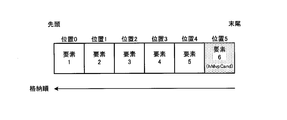
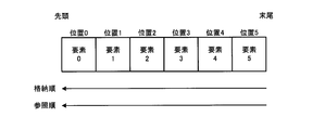
- inter prediction information candidates are included. If inter prediction information having the same value as hMvpCand exists, that element is deleted from the history motion vector predictor candidate list HmvpCandList. On the other hand, if there is no inter prediction information having the same value as the inter prediction information candidate hMvpCand, the top element of the historical motion vector predictor candidate list HmvpCandList is deleted, and the inter prediction information candidate is added at the end of the historical motion vector predictor list HmvpCandList. Add hMvpCand.
- the number of elements of the history motion vector predictor candidate list HmvpCandList provided in the coding information storage memory 111 on the coding side and the coding information storage memory 205 on the decoding side of the present invention is 6.
- the history motion vector predictor candidate list HmvpCandList is initialized in slice units (step S2101 in FIG. 26). Empty all the elements of the historical motion vector predictor candidate list HmvpCandList at the beginning of the slice, and set the number of historical motion vector predictor candidates (current number of candidates) NumHmvpCand registered in the historical motion vector predictor list HmvpCandList to 0. Set.
- the initialization of the history motion vector predictor candidate list HmvpCandList is performed in slice units (the first coding block of a slice), but it may be performed in picture units, tile units, or tree block row units.
- step S2104 It is determined whether or not the inter prediction information candidate hMvpCand to be registered exists (step S2104 in FIG. 26).
- the inter prediction information is set as an inter prediction information candidate hMvpCand to be registered.
- the prediction method determination unit 105 on the encoding side determines the intra prediction mode, the sub-block prediction motion vector mode, or the sub-block merge mode, or the decoding-side bit string decoding unit 201 determines the intra prediction mode, the sub-block prediction motion vector mode
- the history motion vector predictor candidate list HmvpCandList is not updated, and the inter prediction information candidate hMvpCand to be registered does not exist. If the inter prediction information candidate hMvpCand to be registered does not exist, steps S2105 to S2106 are skipped (step S2104 of FIG. 26: NO).
- the processing from step S2105 is performed (step S2104 in FIG. 26: YES).
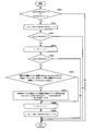
- FIG. 27 is a flowchart of the same element confirmation processing procedure.
- the value of the number of historical motion vector predictor NumHmvpCand is 0 (step S2121 in FIG. 27: NO)
- the historical motion vector predictor candidate list HmvpCandList is empty and the same candidate does not exist, so steps S2122 to S2125 in FIG. 27 are skipped. Then, the same element confirmation processing procedure ends.
- step S2123 is repeated from the history motion vector predictor index hMvpIdx of 0 to NumHmvpCand-1 (step of FIG. 27). S2122 to S2125). First, it is compared whether or not the hMvpIdxth element HmvpCandList[hMvpIdx] counting from 0 in the history motion vector predictor list is the same as the inter prediction information candidate hMvpCand (step S2123 in FIG. 27). If they are the same (step S2123 in FIG.
- step S2123 in FIG. 27: NO hMvpIdx is incremented by 1, and if the history motion vector predictor index hMvpIdx is NumHmvpCand-1 or less, the processing from step S2123 is performed.
- FIG. 28 is a flowchart of the element shift/addition processing procedure of the history motion vector predictor candidate list HmvpCandList in step S2106 of FIG. First, it is determined whether an element stored in the history motion vector predictor candidate list HmvpCandList is removed and then a new element is added, or whether a new element is added without removing the element.
- step S2141 it compares whether or not TRUE (true) or NumHmvpCand is 6 with a flag “identicalCandExist” indicating whether the same candidate exists (step S2141 in FIG. 28).
- the flag indicating whether the same candidate exists is TRUE (true) or the current number of candidates NumHmvpCand satisfies the condition of 6 (YES in step S2141 of FIG. 28)
- the history motion vector predictor candidate list HmvpCandList Add the new element after removing the element stored in. Set the initial value of index i to the value of removeIdx + 1. From this initial value to NumHmvpCand, the element shift processing of step S2143 is repeated.
- Step S2142 to S2144 in FIG. 28 By copying the element of HmvpCandList[ i ] to HmvpCandList[ i - 1 ], the element is shifted forward (step S2143 in FIG. 28) and i is incremented by 1 (steps S2142 to S2144 in FIG. 28). Subsequently, the inter prediction information candidate hMvpCand is added to (NumHmvpCand-1)th HmvpCandList[NumHmvpCand-1] counting from 0 corresponding to the end of the history prediction motion vector candidate list (step S2145 in FIG. 28), and the main history prediction is performed.
- the element shift/addition processing of the motion vector candidate list HmvpCandList ends.
- the condition of TRUE (true) and NumHmvpCand of 6 is satisfied in the flag “identicalCandExist” indicating whether the same candidate exists (step S2141 in FIG. 28: NO)
- it is stored in the history motion vector predictor candidate list HmvpCandList.
- the inter-prediction information candidate hMvpCand is added to the end of the history motion vector predictor candidate list without excluding the elements described (step S2146 in FIG. 28).
- the end of the history motion vector predictor candidate list is the NumHmvpCand th HmvpCandList[NumHmvpCand] counted from 0.
- NumHmvpCand is incremented by 1, and the element shift and addition processing of this history motion vector predictor candidate list HmvpCandList are terminated.
- FIG. 31 is a diagram illustrating an example of update processing of the history motion vector predictor candidate list.
- the history prediction motion vector candidate list HmvpCandList that has registered six elements (inter prediction information)
- it is compared with new inter prediction information in order from the front element of the history prediction motion vector candidate list HmvpCandList.
- FIG. 31A if the new element has the same value as the third element HMVP2 from the top of the history motion vector predictor candidate list HmvpCandList, the element HMVP2 is deleted from the history motion vector predictor list HmvpCandList and the subsequent element HMVP3...
- HMVP5 is shifted (copied) forward one by one, a new element is added to the end of the history motion vector predictor candidate list HmvpCandList (FIG. 31B), and the history motion vector predictor candidate list HmvpCandList is updated (FIG. 31C). ).
- FIG. 29 is a flowchart for explaining the procedure of the history motion vector predictor candidate derivation process.
- step S2201 in FIG. 29 If the current number of motion vector predictor candidates numCurrMvpCand is greater than or equal to the maximum number of elements (here, 2) in the motion vector predictor candidate list mvpListLX, or if the number of historical motion vector predictor candidates is 0 in the value of NumHmvpCand (step S2201 in FIG. 29). 29), the processing of steps S2202 to S2209 in FIG. 29 is omitted, and the history motion vector predictor candidate derivation processing procedure ends.
- the maximum number of elements here, 2
- the number of historical motion vector predictor candidates is 0 in the value of NumHmvpCand
- steps S2203 to S2208 of FIG. 29 are repeated until the index i is 1 to 4 and the number of historical motion vector predictor candidates numCheckedHMVPCand, whichever is smaller (steps S2202 to S2209 of FIG. 29). If the current number of motion vector predictor candidates numCurrMvpCand is 2 or more, which is the maximum number of elements of the motion vector predictor candidate list mvpListLX (step S2203: NO in FIG. 29), the processes in steps S2204 to S2209 in FIG. The history motion vector predictor candidate derivation process procedure ends.
- step S2203 YES in FIG. 29
- the processes after step S2204 in FIG. 29 are performed.
- steps S2205 to S2207 are performed for Y of 0 and 1 (L0 and L1), respectively (steps S2204 to S2208 of FIG. 29).
- the current number of motion vector predictor candidates numCurrMvpCand is 2 or more, which is the maximum number of elements of the motion vector predictor candidate list mvpListLX (step S2205 of FIG. 29: NO)
- the history motion vector predictor candidate derivation process procedure ends.
- step S2205 YES in FIG. 29
- the process from step S2206 onward in FIG. 29 is performed.
- Step S2206 the LY motion vector of the history motion vector predictor candidate HmvpCandList[NumHmvpCand - i] is added to the numCurrMvpCand th element mvpListLX[numCurrMvpCand] counting from 0 in the motion vector predictor list (step in FIG. 29).
- step S2207 the number of current motion vector predictor candidates numCurrMvpCand is incremented by 1.
- the additional process of step S2207 is skipped.
- steps S2205 to S2207 in FIG. 29 are performed in L0 and L1 (steps S2204 to S2208 in FIG. 29).
- the index i is incremented by 1, and when the index i is 4 or less than the number NumHmvpCand of the number of history motion vector predictor candidates, whichever is smaller, the processes in and after step S2203 are performed again (steps S2202 to S2209 in FIG. 29).
- step S404 in FIG. 21 which is a process common to the history merge candidate derivation unit 345 of the encoding-side normal merge mode derivation unit 302 and the history merge candidate derivation unit 445 of the decoding-side normal merge mode derivation unit 402.
- a method of deriving a history merge candidate from the history merge candidate list HmvpCandList, which is a procedure, will be described in detail.
- FIG. 30 is a flowchart for explaining the history merge candidate derivation processing procedure.
- initialization processing is performed (step S2301 in FIG. 30).
- the initial value of the index hMvpIdx is set to 1, and the additional processing from step S2303 to step S2310 in FIG. 30 is repeated from this initial value to NumHmvpCand (steps S2302 to S2311 in FIG. 30). If the number of elements registered in the current merge candidate list numCurrMergeCand is not less than (maximum merge candidate number MaxNumMergeCand-1), merge candidates have been added to all elements in the merge candidate list, so this history merge candidate derivation The process ends (NO in step S2303 of FIG. 30).
- step S2304 When the number of elements numCurrMergeCand registered in the current merge candidate list is (maximum merge candidate number MaxNumMergeCand-1) or less (YES in step S2303 of FIG. 30), the processes of step S2304 and subsequent steps are performed.
- step S2304 set the value of FALSE (same) to sameMotion (step S2304 in FIG. 30). Subsequently, the initial value of the index i is set to 0, and the processes of steps S2306 and S2307 of FIG. 30 are performed from this initial value to 1 (S2305 to S2308 of FIG. 30).
- step S2306 is limited to the case where hMvpIdx is larger than NumHmvpCand-2, mergeCandList[i] is a spatial merge candidate, and isPruned[i] is FALSE (false).
- both sameMotion and isPruned[i] are set to TRUE (step S2307 in FIG. 30). If the values are not the same (NO in step S2306 in FIG. 30), the process in step S2307 is skipped.
- step S2309 in FIG. 30 is completed, whether sameMotion is FALSE (false) is compared (step S2309 in FIG. 30).
- sameMotion is FALSE (false) (in step S2309 in FIG. 30) YES)
- Step S2310 in FIG. 30 The index hMvpIdx is incremented by 1 (step S2302 of FIG. 30), and steps S2302 to S2311 of FIG. 30 are repeated.
- the motion compensation prediction unit 306 acquires the position and size of the block currently subjected to prediction processing in encoding. Further, the motion compensation prediction unit 306 acquires the inter prediction information from the inter prediction mode determination unit 305. A reference index and a motion vector are derived from the acquired inter prediction information, and the reference picture specified by the reference index in the decoded image memory 104 is moved from the same position as the image signal of the prediction block by the amount of the motion vector. After obtaining the image signal, the prediction signal is generated.
- the inter prediction mode in inter prediction is prediction from a single reference picture such as L0 prediction or L1 prediction
- the prediction signal acquired from one reference picture is used as the motion compensation prediction signal
- the inter prediction mode is BI.
- the prediction mode is prediction from two reference pictures, such as prediction
- a weighted average of the prediction signals acquired from the two reference pictures is used as the motion compensation prediction signal
- the motion compensation prediction signal is determined as the prediction method. It is supplied to the section 105.
- the weighted average ratio of bi-prediction is set to 1:1, but the weighted average may be performed using another ratio. For example, the closer the picture interval between the picture to be predicted and the reference picture is, the larger the weighting ratio may be. Further, the weighting ratio may be calculated using a correspondence table between the combination of picture intervals and the weighting ratio.
- the motion compensation prediction unit 406 has the same function as the motion compensation prediction unit 306 on the encoding side.
- the motion compensation prediction unit 406 outputs the inter prediction information from the normal motion vector predictor mode derivation unit 401, the normal merge mode derivation unit 402, the sub block motion vector predictor mode derivation unit 403, and the sub block merge mode derivation unit 404 to the switch 408. To get through.
- the motion compensation prediction unit 406 supplies the obtained motion compensation prediction signal to the decoded image signal superimposing unit 207.
- ⁇ About inter prediction mode> The process of performing prediction from a single reference picture is defined as uni-prediction, and in the case of uni-prediction, either one of the two reference pictures registered in the reference lists L0 and L1 called L0 prediction or L1 prediction is used. Make a prediction.
- FIG. 32 shows a case of uni-prediction, and the reference picture (RefL0Pic) of L0 is at a time before the picture to be processed (CurPic).
- FIG. 33 shows a case where the reference picture of the L0 prediction in the uni-prediction is at a time after the picture to be processed.
- the L0 prediction reference picture in FIGS. 32 and 33 may be replaced with the L1 prediction reference picture (RefL1Pic) to perform single prediction.
- FIG. 34 shows a case where the reference picture for bi-prediction and L0 prediction is at a time before the processing target picture, and the L1 prediction reference picture is at a time after the processing target picture.
- FIG. 35 illustrates a case where bi-prediction reference pictures for L0 prediction and reference pictures for L1 prediction are at a time before the picture to be processed.
- FIG. 36 shows a case in which bi-prediction reference pictures for L0 prediction and reference pictures for L1 prediction are at times after the picture to be processed.
- L0 prediction and L1 prediction may be performed using the same reference picture. Note that the determination as to whether the motion-compensated prediction is performed by uni-prediction or bi-prediction is made based on information (for example, a flag) indicating whether or not L0 prediction is used and whether or not L1 prediction is used. It
- ⁇ About reference index> In the embodiment of the present invention, in order to improve the accuracy of motion compensation prediction, it is possible to select the optimum reference picture from a plurality of reference pictures in motion compensation prediction. Therefore, the reference picture used in the motion compensation prediction is used as a reference index, and the reference index is encoded in the bitstream together with the differential motion vector.
- the motion compensation prediction unit 306 when the inter prediction mode determination unit 305 selects the inter prediction information by the normal motion vector predictor mode derivation unit 301, as shown in the inter prediction unit 102 on the encoding side in FIG. Acquires this inter prediction information from the inter prediction mode determination unit 305, derives the inter prediction mode, reference index, and motion vector of the block currently being processed, and generates a motion compensation prediction signal.
- the generated motion compensation prediction signal is supplied to the prediction method determination unit 105.
- the motion vector predictor mode deriving unit 401 acquires the inter prediction information, derives the inter prediction mode, the reference index, and the motion vector of the currently processed block, and generates the motion compensation prediction signal.
- the generated motion compensation prediction signal is supplied to the decoded image signal superimposing unit 207.
- ⁇ Motion compensation processing based on normal merge mode> In the motion compensation prediction unit 306, when the inter prediction mode determination unit 305 selects the inter prediction information by the normal merge mode derivation unit 302, as shown in the inter prediction unit 102 on the encoding side in FIG. This inter prediction information is acquired from the inter prediction mode determination unit 305, the inter prediction mode, the reference index, and the motion vector of the currently processed block are derived, and the motion compensation prediction signal is generated. The generated motion compensation prediction signal is supplied to the prediction method determination unit 105.
- the motion compensation prediction unit 406 when the switch 408 is connected to the normal merge mode derivation unit 402 in the decoding process as shown in the inter prediction unit 203 on the decoding side in FIG. 22, the normal merge mode.
- the inter-prediction information is obtained by the derivation unit 402, the inter-prediction mode, reference index, and motion vector of the block currently being processed are derived, and a motion-compensated prediction signal is generated.
- the generated motion compensation prediction signal is supplied to the decoded image signal superimposing unit 207.
- the motion compensation prediction unit 306 As shown in the inter prediction unit 102 on the coding side in FIG. 16, when the inter prediction mode determination unit 305 selects the inter prediction information by the sub block prediction motion vector mode derivation unit 303. For this, the inter prediction information is acquired from the inter prediction mode determination unit 305, the inter prediction mode, the reference index, and the motion vector of the currently processed block are derived to generate a motion compensation prediction signal. The generated motion compensation prediction signal is supplied to the prediction method determination unit 105.
- the motion compensation prediction unit 406 as shown in the inter prediction unit 203 on the decoding side in FIG. 22, when the switch 408 is connected to the sub-block motion vector predictor mode derivation unit 403 during the decoding process,
- the inter-prediction motion vector mode derivation unit 403 acquires inter-prediction information, derives the inter-prediction mode, reference index, and motion vector of the currently processed block, and generates a motion-compensated prediction signal.
- the generated motion compensation prediction signal is supplied to the decoded image signal superimposing unit 207.
- ⁇ Motion compensation processing based on sub-block merge mode> In the motion compensation prediction unit 306, when the inter prediction mode determination unit 305 selects the inter prediction information by the sub block merge mode derivation unit 304, as shown in the inter prediction unit 102 on the encoding side in FIG.
- the inter prediction information is acquired from the inter prediction mode determination unit 305, the inter prediction mode, the reference index, and the motion vector of the currently processed block are derived, and the motion compensation prediction signal is generated.
- the generated motion compensation prediction signal is supplied to the prediction method determination unit 105.
- the motion compensation prediction unit 406 as shown in the inter prediction unit 203 on the decoding side in FIG. 22, when the switch 408 is connected to the sub block merge mode derivation unit 404 in the decoding process, the sub block The inter prediction information obtained by the merge mode derivation unit 404 is acquired, the inter prediction mode, the reference index, and the motion vector of the block currently being processed are derived, and the motion compensation prediction signal is generated. The generated motion compensation prediction signal is supplied to the decoded image signal superimposing unit 207.
- motion compensation by an affine model can be used based on the following flags.
- the following flags are reflected in the following flags based on the inter prediction condition determined by the inter prediction mode determination unit 305 in the encoding process, and are encoded in the bitstream.
- ⁇ sps_affine_enabled_flag indicates whether motion compensation using an affine model can be used in inter prediction. If sps_affine_enabled_flag is 0, the motion compensation by the affine model is suppressed in sequence units. Also, inter_affine_flag and cu_affine_type_flag are not transmitted in the CU (coding block) syntax of the coded video sequence. If sps_affine_enabled_flag is 1, motion compensation by an affine model can be used in the coded video sequence.
- ⁇ sps_affine_type_flag indicates whether motion compensation using a 6-parameter affine model can be used in inter prediction. If sps_affine_type_flag is 0, the motion compensation is not performed by the 6-parameter affine model. Also, cu_affine_type_flag is not transmitted in the CU syntax of the coded video sequence. If sps_affine_type_flag is 1, motion compensation by a 6-parameter affine model can be used in a coded video sequence. If sps_affine_type_flag does not exist, it shall be 0.
- inter_affine_flag 1 in the CU currently being processed
- the affine model is used to generate the motion compensation prediction signal of the CU currently being processed. Motion compensation is used. If inter_affine_flag is 0, the affine model is not used for the CU currently being processed. If inter_affine_flag does not exist, it shall be 0.
- a reference index or motion vector is derived in sub-block units, so a motion-compensated prediction signal is generated using the reference index or motion vector that is the processing target in sub-block units.
- the 4-parameter affine model is a mode in which the motion vector of a sub-block is derived from the four parameters of the horizontal and vertical components of the motion vector of each of the two control points, and motion compensation is performed in sub-block units.
- the reference order when the history motion vector predictor candidate list is used may be reversed from the storage order.
- the history motion vector predictor candidate list is stored from the end side and the motion information on the head side of the history motion vector predictor candidate list is stored so as to be arranged in an order in which the motion information is older than the end side
- the storage state is the same as that of this embodiment.
- the history prediction motion vector candidate list is stored so that the head side is arranged in the order of newer motion information than the tail side, the storage state is opposite to that shown in the present embodiment.
- the reference order is configured to be used in the same direction as the storage order and to be used in the opposite direction to the storage order. May be. That is, the motion information stored in the history motion vector predictor candidate list can be referred to in order from the old motion information to the newly added motion information, and the motion information stored in the history motion vector predictor candidate list can be referred to.
- the case where the newly added motion information can be sequentially referred to the old motion information and the case where the history motion vector predictor candidate list is used may be selectively used.
- an element having the same information may be searched for from the history motion vector predictor candidate list, and the deletion processing may not be performed.
- the normal motion vector predictor mode when deriving the normal motion vector predictor using the history motion vector predictor candidate list HmvpCandList, search for elements having the same information from the motion vector predictor candidate list, It may be configured not to perform a process in which an element having information is not a normal motion vector predictor candidate.
- the inter prediction information used by the inter prediction in the current block is set as the inter prediction information candidate hMvpCand to be registered, and the history prediction motion vector candidate list HmvpCandList is used as the history that has been used in the past. Register with.
- the history motion vector predictor candidate list has a list structure capable of storing six elements, and first-in first-out FIFO (First-In, First Out) method in which the elements stored first are sequentially extracted. Is the basic storage operation.
- the maximum number of elements that can be stored in the HmvpCandList is described as 6 as an agreement on the encoding side and the decoding side, but it is not particularly limited and may be 6 or more. Further, the maximum number of elements that can be stored in the HmvpCandList may be five or less.
- the HmvpCandList may be configured with the maximum number of elements equivalent to the maximum number of inter prediction information candidates, such as the maximum number of elements of the motion vector predictor list mvpListLX, the maximum number of merge candidates, and the maximum number of subblock merge candidates. Further, the HmvpCandList may be configured so as to be linked to the maximum number of elements of inter prediction information candidates in each mode.
- HmvpCandList can store 6 elements from position 0 at the beginning of the list to position 5 at the end of the list, and can fill the elements from position 0 to position 5.
- the positions 0 to 5 are managed as the history motion vector predictor index hMvpIdx.
- position 0 can be expressed as hMVpIdx[0]
- position 5 can be expressed as hMVpIdx[5].
- the number of storage elements of the HmvpCandList is managed by NumHmvpCand, and the increase/decrease of storage elements is managed in the range of 0 to 6, which is the maximum number of elements.
- Modification 1 As a modified example of the first embodiment, the following processing is performed on the history motion vector predictor candidate list. ⁇ Search for the same candidate in the history motion vector predictor candidate list>
- the inter prediction information candidate hMvpCand to be registered is included in the inter prediction information registered in the historical motion vector predictor list HmvpCandList.
- the element (inter prediction information) is deleted from the history motion vector predictor candidate list HmvpCandList.
- the same candidate deletion process will be referred to as the same candidate deletion process.
- the same candidate deletion process is not performed. Further, when using the history motion vector predictor candidate list HmvpCandList while referring to the history motion vector predictor candidate list in the reverse order of the storage order in which new elements are added to the end of the motion vector predictor candidate list, as shown in FIG. The configuration is such that the same candidate deletion process is not performed.
- the motion information which is the history motion vector predictor candidate stored in the motion vector predictor motion vector candidate list HmvpCandList, is referenced from the old motion information by referring in the reverse order of the storage order from the end side.
- FIG. 9 is a flowchart illustrating a procedure of a history motion vector predictor candidate derivation process in a case where the newly added motion information is used while being referred to in order and the same candidate deletion process is not performed.
- the inter prediction information used when performing the inter prediction in the normal prediction vector mode or the normal merge mode is set as the inter prediction information candidate hMvpCand to be registered, and the coding information storage memory 111 on the coding side and the coding information storage memory on the decoding side
- Inter prediction information candidates hMvpCand to be registered are added in order from the closest vacant position.
- the first element (inter prediction information) of the history motion vector predictor candidate list HmvpCandList is deleted, and the inter motion prediction information to be registered at the end of the history motion vector predictor list HmvpCandList.
- Add candidate hMvpCand The number of elements of the history motion vector predictor candidate list HmvpCandList provided in the encoding side encoding information storage memory 111 and the decoding side encoding information storage memory 205 according to the present embodiment is six. First, initial setting is performed in slice units.
- the historical motion vector predictor candidate list HmvpCandList is initialized at the beginning of the slice, and the number of historical motion vector predictor candidates NumHmvpCand registered in the historical motion vector predictor list HmvpCandList is set to 0 (step S2401 in FIG. 38). .. Subsequently, the following update processing of the history motion vector predictor candidate list HmvpCandList is repeatedly performed for each coded block in the slice (steps S2402 to S2407 in FIG. 38). It is determined whether or not the inter prediction information candidate hMvpCand to be registered is present in the history motion vector predictor candidate list HmvpCandList (step S2404 in FIG. 38).
- the The prediction mode is hMvpCand.
- the prediction method determination unit 105 on the encoding side determines the intra prediction mode, the sub-block prediction motion vector mode, or the sub-block merge mode, or the decoding-side bit string decoding unit determines the intra prediction mode, the sub-block prediction motion vector mode, or When decoded in the sub-block merge mode, the history motion vector predictor candidate list HmvpCandList is not updated, and there is no inter prediction information candidate hMvpCand to be registered.
- step S2406 is skipped (step S2404 of FIG. 38: NO).
- step S2404 of FIG. 38: YES the processing from step S2406 is performed (step S2404 of FIG. 38: YES).
- step S2406 the elements of the history motion vector predictor candidate list HmvpCandList are shifted and added (step S2406 in FIG. 38).
- the element shift/addition processing procedure of the history motion vector predictor candidate list HmvpCandList in step S2406 of FIG. 38 is configured as follows. 39 is a flowchart of the element shift/addition processing procedure of the history motion vector predictor candidate list HmvpCandList in step S2406 of FIG. First, it is determined whether a new element is added after removing the head element stored in the history motion vector predictor candidate list HmvpCandList, or whether a new element is added without removing the element. Specifically, it is compared whether NumHmvpCand is 6 (step S2541 in FIG. 39). When NumHmvpCand is 6 (step S2541 of FIG.
- a new element is added after removing the head element stored in the history motion vector predictor candidate list HmvpCandList.
- Set the initial value of index i to a value of 1.
- the element shift process of step S2543 is repeated. (Steps S2542 to S2544 in FIG. 39).
- the element is shifted forward (step S2543 in FIG. 39) and i is incremented by 1 (steps S2542 and S2544 in FIG. 39).
- the inter prediction information candidate hMvpCand is added to the (NumHmvpCand-1)th HmvpCandList [NumHmvpCand-1] counting from 0 corresponding to the end of the history prediction motion vector candidate list (step S2545 in FIG. 39), and the main history prediction is performed.
- the element shift/addition processing of the motion vector candidate list HmvpCandList ends.
- NumHmvpCand is not 6 (step S2541 in FIG. 39: NO)
- a new element is added without excluding the elements stored in the history motion vector predictor candidate list HmvpCandList.
- the inter prediction information candidate hMvpCand is added to the (NumHmvpCand-1)th HmvpCandList [NumHmvpCand] counting from 0 corresponding to the end of the history motion vector predictor candidate list, and NumHmvpCand is incremented by 1 (step S2546 in FIG. 39).
- the element shift/addition processing of the history motion vector predictor candidate list HmvpCandList ends. By performing the processing as shown in FIG. 39, it is possible to omit the processing of checking and deleting the same candidate, the setting of variables for executing the processing, and the comparison processing, and it is possible to reduce the processing amount.
- Modification 3 While using the history motion vector predictor candidate list HmvpCandList while referring to the order reverse to the storage order of adding new motion information from the end side, the motion that is the motion vector predictor motion vector candidate stored in HmvpCandList is used. The case where the same candidate deletion process is not performed while using the information while sequentially referring to the old motion information and the newly added motion information will be described.
- the reference order is in the same direction as the storage order to be added from the end, the forward order mode in which the old motion information is referred to from the newly added motion information, and the reference order is the end.
- a reverse order mode that refers to the newly added motion information from the old motion information in the reverse direction of the storage order of adding new motion information from the side is prepared, and the reference order of the history prediction motion vector candidate list HmvpCandList is switched.
- the forward reference mode and the reverse order mode can be switched by using the history reference flag information for.
- This history reference flag is included in the syntax element of the coded bitstream and transmitted to the decoding side, and the decoding side acquires the coded bitstream having this history reference flag as the syntax element so that it can be decoded.
- the motion vector predictor candidate list mvpListLX when deriving the motion vector predictor candidate list mvpListLX, it is configured as follows. In particular, when deriving the motion vector predictor candidate list mvpListLX, the history motion vector predictor candidate list HmvpCandList is used while referring from the beginning in the reverse order of the storage order newly added from the end, and the motion vector predictor candidate list In the process of adding a motion vector predictor candidate to the motion vector predictor candidate list, the process of determining whether or not the same motion vector predictor is included in the motion vector predictor candidate list is configured not to be performed.
- FIG. 47 shows a case where, when deriving the motion vector predictor candidate list mvpListLX, the history motion vector predictor candidate list HmvpCandList is used while referring to it in the reverse order of the storage order, and the same candidate deletion process is not performed.
- 14 is a flowchart illustrating a procedure of a history motion vector predictor candidate derivation process.
- step S2601 in FIG. 47: NO the processing of steps S2602 to S2609 of FIG. 47 is omitted, and the history motion vector predictor candidate derivation processing procedure ends.
- the current number numCurrMvpCand of motion vector predictor candidates is smaller than 2, which is the maximum number of elements of the motion vector predictor list mvpListLX (step S2601 of FIG. 47: YES)
- the processes of steps S2602 to S2609 of FIG. 47 are performed.
- steps S2603 to S2608 of FIG. 47 is repeated until the index i is 0 to 4 and the number NumHmvpCand of the number of history motion vector predictor candidates, whichever is smaller (step S2602 to S2609 of FIG. 47).
- the number numCurrMvpCand of the current motion vector predictor candidates is 2 or more, which is the maximum number of elements of the motion vector predictor list mvpListLX (step S2603 of FIG. 47: NO)
- the motion vector predictor candidate derivation process procedure ends.
- step S2603 If the current number of motion vector predictor candidates numCurrMvpCand is smaller than 2, which is the maximum number of elements of the motion vector predictor list mvpListLX (step S2603: YES in FIG. 47 ), the process after step S2604 in FIG. 47 is performed.
- steps S2605 to S2607 are performed for indexes Y of 0 and 1 (L0 and L1), respectively (steps S2604 to S2608 of FIG. 47).
- the number numCurrMvpCand of the current motion vector predictor candidates is 2 or more, which is the maximum number of elements of the motion vector predictor list mvpListLX (step S2605 of FIG. 47: NO)
- the motion vector predictor candidate derivation process procedure ends. If the current number numCurrMvpCand of motion vector predictor candidates is smaller than 2, which is the maximum number of elements of the motion vector predictor list mvpListLX (step S2605 of FIG. 47: YES), the process of step S2606 and subsequent steps of FIG. 47 is performed.
- the reference index of LY of the history motion vector predictor candidate list HmvpCandList[i] is the element of the same reference index as the reference index refIdxLX of the motion vector to be encoded/decoded (step S2606 of FIG. 47: YES)
- the LY motion vector of the history motion vector predictor candidate HmvpCandList[i] is added to the numCurrMvpCand th element mvpListLX[numCurrMvpCand ] counting from 0 in the motion vector predictor candidate list (step S2607 in FIG. 47), and the current motion vector predictor candidate. Increment the number numCurrMvpCand by 1.
- step S2607 is added. Skip processing.
- steps S2605 to S2607 in FIG. 47 are performed in L0 and L1 (steps S2604 to S2608 in FIG. 47).
- the index i is incremented by 1 (steps S2602 and S2609 of FIG. 47), and when the index i is 4 or the number NumHmvpCand of the number of historical motion vector predictor candidates, whichever is smaller, -1 or less, the processes of step S2603 and thereafter are performed again. 47, steps S2602 to S2609).
- the motion information which is the history motion vector predictor candidate stored in HmvpCandList
- the motion information which is the history motion vector predictor candidate stored in HmvpCandList
- new motion information is added from the old motion information. It is possible to reduce the possibility that the same candidate will be added to the motion vector predictor candidate list by sequentially referring to the motion information.
- Modification 1 In the second embodiment, when deriving the motion vector predictor candidate list mvpListLX, the history motion vector predictor candidate list HmvpCandList is used while referring from the beginning in the order opposite to the storage order newly added from the end, The case where the same candidate deletion process is not performed is described.
- the modified example of the second embodiment as shown below, only the reference order of the history motion vector predictor candidate list HmvpCandList is referenced from the beginning in the order opposite to the storage order newly added from the end, The newly added motion information is referred to from the old motion information, and the identical candidate deletion process is performed as it is.
- FIG. 48 illustrates a history motion vector predictor candidate derivation process procedure in the case where the history motion vector predictor candidate list HmvpCandList is used while referring to the order reverse to the storage order and the same candidate deletion process is not performed. It is a flowchart to do.
- step S2801 in FIG. 48: No If the current number of motion vector predictor candidates numCurrMvpCand is greater than or equal to the maximum number of elements in the motion vector predictor list mvpListLX (here, 2) or the number of history motion vector predictor candidates is 0 for the value NumHmvpCand (step S2801 in FIG. 48: No), and the processing of steps S2802 to S2809 of FIG. 48 is omitted, and the history motion vector predictor candidate derivation processing procedure ends. If the current number numCurrMvpCand of motion vector predictor candidates is smaller than 2, which is the maximum number of elements of the motion vector predictor list mvpListLX (step S2801: YES in FIG. 48), the processes of steps S2802 to S2809 in FIG. 48 are performed.
- steps S2803 to S2808 of FIG. 48 are repeated until the index i is 0 to 4 and the number NumHmvpCand of the number of history motion vector predictor candidates, whichever is smaller (-1) (steps S2802 to S2809 of FIG. 48). If the current number of motion vector predictor candidates numCurrMvpCand is 2 or more, which is the maximum number of elements of the motion vector predictor list mvpListLX (step S2803 of FIG. 48: NO), the processes of steps S2804 to S2809 of FIG. The motion vector predictor candidate derivation process procedure ends.
- step S2804 If the current number of motion vector predictor candidates numCurrMvpCand is smaller than 2, which is the maximum number of elements of the motion vector predictor list mvpListLX (step S2803 of FIG. 48: YES), the process of step S2804 and subsequent steps of FIG. 48 is performed.
- steps S2805 to S2807 are performed for indexes Y of 0 and 1 (L0 and L1), respectively (steps S2804 to S2808 in FIG. 48).
- the current number of motion vector predictor candidates numCurrMvpCand is 2 or more, which is the maximum number of elements of the motion vector predictor list mvpListLX (step S2805 of FIG. 48: NO)
- the motion vector predictor candidate derivation process procedure ends. If the current number of motion vector predictor candidates numCurrMvpCand is smaller than 2, which is the maximum number of elements of the motion vector predictor list mvpListLX (step S2805 of FIG. 48: YES), the process of step S2806 and subsequent steps of FIG. 48 is performed.
- the reference index of LY of the history motion vector predictor candidate list HmvpCandList[i] is the element of the same reference index as the reference index refIdxLX of the motion vector to be encoded/decoded, and is different from any element of the motion vector predictor list mvpListLX. If there is an element (step S2806 of FIG. 48: YES), the LY motion vector of the history motion vector predictor candidate HmvpCandList[i] is added to the numCurrMvpCand th element mvpListLX[numCurrMvpCand ] counting from 0 in the motion vector predictor candidate list. (Step S2807 in FIG.
- step S2806 of FIG. 48 NO
- step S2807 the additional processing of step S2807 is skipped.
- steps S2805 to S2807 in FIG. 48 are performed in L0 and L1 (steps S2804 to S2808 in FIG. 48).
- step S2803 When the index i is incremented by 1, and the index i is 4 or the number NumHmvpCand of the number of history motion vector predictor candidates, whichever is smaller, -1 or less, the processes after step S2803 are performed again (steps S2802 to S2809 in FIG. 48).
- the same candidate deletion process is configured to be performed as it is, and the motion information that is the history prediction motion vector candidate stored in the HmvpCandList is updated from the old motion information to the new motion information.
- Modification 2 As a modification of the second embodiment, when deriving the motion vector predictor candidate list mvpListLX, the element shift/addition processing procedure of the history motion vector predictor candidate list HmvpCandList of step S2406 of FIG. 38 is shown in FIG. 39. To configure. The description of FIG. 39 is omitted because it is similar to the above. By performing the processing as shown in FIG. 39, it is possible to omit the processing of checking and deleting the same candidate, the setting of variables for executing the processing, and the comparison processing, and it is possible to reduce the processing amount.
- the history motion vector predictor candidate list HmvpCandList is used while referring to the reverse order of the storage order in which new motion information is added from the end side.
- the motion information stored in the HmvpCandList which is a candidate motion vector predictor for prediction, is used while sequentially referencing from the old motion information to the newly added motion information, without performing the same candidate deletion process.
- the reference order is in the same direction as the storage order added from the end, and the forward order mode in which the old motion information is referred to from the newly added motion information, and the reference order is the end.
- a reverse order mode that refers to the newly added motion information from the old motion information in the reverse direction of the storage order of adding new motion information from the side is prepared, and the reference order of the history prediction motion vector candidate list HmvpCandList is switched.
- the forward reference mode and the reverse order mode can be switched by using the history reference flag information for.
- This history reference flag is included in the syntax element of the coded bitstream and transmitted to the decoding side, and the decoding side acquires the coded bitstream having this history reference flag as the syntax element so that it can be decoded.
- the configuration is as follows. Particularly, the reference order when using the history motion vector predictor candidate list is changed so that the history motion vector candidate list is used while being referred to in order from old motion information to newly added motion information. Further, when a new element is added to the merge candidate list, an element having the same information is searched for from the history motion vector predictor candidate list, and the deletion processing is changed so as not to be performed. Further, in the normal merge mode, when deriving a normal merge candidate using the history motion vector predictor candidate list HmvpCandList, search for elements having the same information from the history motion vector predictor candidate list, and elements having the same information.
- FIG. 40 shows the history merge candidate derivation in the case where the history candidate motion vector candidate list HmvpCandList is used while sequentially referencing the old motion information to the newly added motion information and not performing the same candidate deletion process. It is a flow chart explaining a processing procedure.
- initialization processing is performed (step S2701 in FIG. 40). Set the variable numOrigMergeCand to the number of elements registered in the current merge candidate list, numCurrMergeCand.
- the initial value of the index hMvpIdx is set to 0, and the additional processing from step S2703 to step S2710 in FIG. 40 is repeated from this initial value to NumHmvpCand-1 (steps S2702 to S2711 in FIG. 40). If the number of elements registered in the current merge candidate list numCurrMergeCand is not less than (maximum merge candidate number MaxNumMergeCand-1), merge candidates have been added to all elements in the merge candidate list, so this history merge candidate derivation The process ends (step S2703 of FIG. 40: NO).
- Step S2710 If the number of elements numCurrMergeCand registered in the current merge candidate list is (maximum merge candidate number MaxNumMergeCand-1) or less, the processing from step S2710 is performed. (Step S2703 of FIG. 40: YES).
- the hMvpIdx th element HmvpCandList[hMvpIdx] of the history motion vector predictor candidate list is added to the numCurrMergeCand th mergeCandList[numCurrMergeCand] of the merge candidate list, and numCurrMergeCand is incremented by 1 (step S2710 in FIG. 40).
- the index hMvpIdx is incremented by 1 (step S2702 of FIG. 40), and the repeating processing of steps S2702 to S2711 of FIG. 40 is performed.
- the process of deriving the history merge candidate is completed.
- HmvpCandList which is a candidate motion vector predictor for motion vector prediction
- various motion information can be added to the merge candidate list. It becomes possible to do.
- the motion newly added from the old motion information is deleted. By making it possible to refer to the information in order, it is possible to reduce the possibility that the same candidate is added to the merge candidate list.
- Modification 1 As a modification of the third embodiment, when deriving a merge candidate list, the same candidate deletion process is not performed when adding an element to the history motion vector predictor candidate list HmvpCandList as shown in FIG. To configure.
- the description of FIG. 38 is omitted because it is similar to the above. By performing the processing as shown in FIG. 38, it is possible to omit the processing of checking and deleting the same candidate, the setting of variables for executing the processing, and the comparison processing, and it is possible to reduce the processing amount.
- Modification 2 As a modification of the third embodiment, when deriving the merge candidate list, the element shift/addition processing procedure of the history motion vector predictor candidate list HmvpCandList of step S2406 of FIG. 38 is configured as shown in FIG. .. The description of FIG. 39 is omitted because it is similar to the above. By performing the processing as shown in FIG. 39, it is possible to omit the processing of checking and deleting the same candidate, the setting of variables for executing the processing, and the comparison processing, and it is possible to reduce the processing amount.
- the motion information that is the history motion vector predictor candidate stored in the HmvpCandList is referenced in order from the old motion information to the newly added motion information.
- the forward order mode of referring to the old motion information from the motion information of which the reference order is newly added, and the newly added motion information of the motion information of the old reference order are referred to.
- the reverse order mode is prepared, and the history reference flag information for switching the reference order of the history motion vector predictor candidate list HmvpCandList is used to switch between the forward order mode and the reverse order mode.
- This history reference flag is included in the syntax element of the coded bitstream and transmitted to the decoding side, and the decoding side acquires the coded bitstream having this history reference flag as the syntax element so that it can be decoded.
- the bitstream output by the image encoding device has a specific data format so that the bitstream can be decoded according to the encoding method used in the embodiments. There is. Also, the image decoding device corresponding to this image encoding device can decode the bit stream of this specific data format.
- a wired or wireless network is used to exchange a bitstream between the image encoding device and the image decoding device, even if the bitstream is converted into a data format suitable for the transmission mode of the communication path and then transmitted. Good.
- a bit stream output from the image coding device is converted into coded data in a data format suitable for the transmission mode of the communication path and transmitted to the network, and a bit stream is generated by receiving the coded data from the network.
- a receiving device that restores to the image decoding device and supplies the image decoding device with the receiving device.
- the transmission device includes a memory that buffers the bitstream output by the image encoding device, a packet processing unit that packetizes the bitstream, and a transmission unit that transmits the packetized encoded data via a network.
- the receiving device receives a packetized encoded data via a network, a memory for buffering the received encoded data, a packet processing of the encoded data to generate a bit stream, and an image decoding And a packet processing unit provided to the device.
- a display unit may be added by adding a display unit for displaying an image decoded by the image decoding device to the configuration.
- the display unit reads the decoded image signal generated by the decoded image signal superimposing unit 207 and stored in the decoded image memory 208, and displays it on the screen.
- an image pickup unit may be added to the configuration, and the picked-up image may be input to the image coding device to form the image pickup device.
- the imaging unit inputs the captured image signal to the block division unit 101.
- FIG. 37 shows an example of the hardware configuration of the encoding/decoding device of this embodiment.
- the encoding/decoding device includes the configurations of the image encoding device and the image decoding device according to the embodiment of the present invention.
- the encoding/decoding device 9000 includes a CPU 9001, a codec IC 9002, an I/O interface 9003, a memory 9004, an optical disk drive 9005, a network interface 9006, and a video interface 9009, and each unit is connected by a bus 9010.
- the image encoding unit 9007 and the image decoding unit 9008 are typically implemented as a codec IC 9002.
- the image encoding process of the image encoding device according to the embodiment of the present invention is executed by the image encoding unit 9007, and the image decoding process of the image decoding device according to the embodiment of the present invention is performed by the image decoding unit 9008.
- the I/O interface 9003 is realized by a USB interface, for example, and is connected to an external keyboard 9104, mouse 9105, and the like.
- the CPU 9001 controls the encoding/decoding device 9000 to execute an operation desired by the user, based on the user operation input via the I/O interface 9003.
- the user's operations using the keyboard 9104, mouse 9105, etc. include selection of which function of encoding or decoding is to be executed, setting of encoding quality, bitstream input/output destination, image input/output destination, and the like.
- the optical disc drive 9005 When the user desires an operation of reproducing an image recorded on the disc recording medium 9100, the optical disc drive 9005 reads a bitstream from the inserted disc recording medium 9100 and outputs the read bitstream via the bus 9010. It is sent to the image decoding unit 9008 of the codec IC 9002.
- the image decoding unit 9008 executes the image decoding processing in the image decoding apparatus according to the embodiment of the present invention on the input bitstream, and sends the decoded image to the external monitor 9103 via the video interface 9009.
- the encoding/decoding device 9000 has a network interface 9006 and can be connected to an external distribution server 9106 and a mobile terminal 9107 via the network 9101.
- the network interface 9006 sets the input from the input disk recording medium 9100. Instead of reading the bitstream, the bitstream is acquired from the network 9101. Further, when the user desires to reproduce the image recorded in the memory 9004, the image decoding processing in the image decoding device according to the embodiment of the present invention is performed on the bitstream recorded in the memory 9004. To do.
- the video interface 9009 inputs the image from the camera 9102, and via the bus 9010, the image encoding unit 9007 of the codec IC 9002. Send to.
- the image coding unit 9007 executes the image coding process in the image coding apparatus according to the embodiment of the present invention on the image input via the video interface 9009 to create a bitstream. Then, the bit stream is sent to the memory 9004 via the bus 9010.
- the optical disc drive 9005 writes the bitstream to the inserted disc recording medium 9100.
- Such a hardware configuration is realized, for example, by replacing the codec IC 9002 with the image encoding unit 9007 or the image decoding unit 9008.
- the above-mentioned processing relating to encoding and decoding may be realized as a transmission, storage, and reception device using hardware, and is also stored in a ROM (read only memory), a flash memory, or the like. It may be realized by firmware or software such as a computer.
- the firmware program and the software program may be provided by being recorded in a recording medium readable by a computer or the like, provided from a server through a wired or wireless network, or terrestrial or satellite digital broadcasting data broadcasting. May be provided as.
- 100 image encoding device 101 block division unit, 102 inter prediction unit, 103 intra prediction unit, 104 decoded image memory, 105 prediction method determination unit, 106 residual generation unit, 107 orthogonal transform/quantization unit, 108 bit string encoding Part, 109 dequantization/inverse orthogonal transformation part, 110 decoded image signal superposition part, 111 encoded information storage memory, 200 image decoding device, 201 bit string decoding part, 202 block division part, 203 inter prediction part 204 intra prediction part, 205 coded information storage memory 206 dequantization/inverse orthogonal transformation unit, 207 decoded image signal superposition unit, 208 decoded image memory.
Landscapes
- Engineering & Computer Science (AREA)
- Multimedia (AREA)
- Signal Processing (AREA)
- Compression Or Coding Systems Of Tv Signals (AREA)
Abstract
Description
実施の形態では、所定の大きさで符号化・復号処理対象画像を均等分割する。この単位をツリーブロックと定義する。図4では、ツリーブロックのサイズを128x128画素としているが、ツリーブロックのサイズはこれに限定されるものではなく、任意のサイズを設定してよい。処理対象(符号化処理においては符号化対象、復号処理においては復号対象に対応する。)のツリーブロックは、ラスタスキャン順、すなわち左から右、上から下の順序で切り替わる。各ツリーブロックの内部は、さらに再帰的な分割が可能である。ツリーブロックを再帰的に分割した後の、符号化・復号の対象となるブロックを符号化ブロックと定義する。また、ツリーブロック、符号化ブロックを総称してブロックと定義する。適切なブロック分割を行うことにより効率的な符号化が可能となる。ツリーブロックのサイズは、符号化装置と復号装置で予め取り決めた固定値とすることもできるし、符号化装置が決定したツリーブロックのサイズを復号装置に伝送するような構成をとることもできる。ここでは、ツリーブロックの最大サイズを128x128画素、ツリーブロックの最小サイズを16x16画素とする。また、符号化ブロックの最大サイズを64x64画素、符号化ブロックの最小サイズを4x4画素とする。
処理対象符号化ブロック単位で、処理対象画像の処理済み画像信号から予測を行うイントラ予測(MODE_INTRA)、及び処理済み画像の画像信号から予測を行うインター予測(MODE_INTER)を切り替える。
処理済み画像は、符号化処理においては符号化が完了した信号を復号した画像、画像信号、ツリーブロック、ブロック、符号化ブロック等に用いられ、復号処理においては復号が完了した画像、画像信号、ツリーブロック、ブロック、符号化ブロック等に用いられる。
このイントラ予測(MODE_INTRA)とインター予測(MODE_INTER)を識別するモードを予測モード(PredMode)と定義する。予測モード(PredMode)はイントラ予測(MODE_INTRA)、またはインター予測(MODE_INTER)を値として持つ。
処理済み画像の画像信号から予測を行うインター予測では、複数の処理済み画像を参照ピクチャとして用いることができる。複数の参照ピクチャを管理するため、L0(参照リスト0)とL1(参照リスト1)の2種類の参照リストを定義し、それぞれ参照インデックスを用いて参照ピクチャを特定する。PスライスではL0予測(Pred_L0)が利用可能である。BスライスではL0予測(Pred_L0)、L1予測(Pred_L1)、双予測(Pred_BI)が利用可能である。L0予測(Pred_L0)はL0で管理されている参照ピクチャを参照するインター予測であり、L1予測(Pred_L1)はL1で管理されている参照ピクチャを参照するインター予測である。双予測(Pred_BI)はL0予測とL1予測が共に行われ、L0とL1のそれぞれで管理されている1つずつの参照ピクチャを参照するインター予測である。L0予測、L1予測、双予測を特定する情報を、インター予測モードと定義する。以降の処理において出力に添え字LXが付いている定数、変数に関しては、L0、L1ごとに処理が行われることを前提とする。
予測動きベクトルモードは、予測動きベクトルを特定するためのインデックス、差分動きベクトル、インター予測モード、参照インデックスを伝送し、処理対象ブロックのインター予測情報を決定するモードである。予測動きベクトルは、処理対象ブロックに隣接する処理済みブロック、または処理済み画像に属するブロックで処理対象ブロックと同一位置またはその付近(近傍)に位置するブロックから導出した予測動きベクトル候補と、予測動きベクトルを特定するためのインデックスから導出する。
マージモードは、差分動きベクトル、参照インデックスを伝送せずに、処理対象ブロックに隣接する処理済みブロック、または処理済み画像に属するブロックで処理対象ブロックと同一位置またはその付近(近傍)に位置するブロックのインター予測情報から、処理対象ブロックのインター予測情報を導出するモードである。
図11は、予測動きベクトルモード、マージモードで、インター予測情報を導出するために参照する参照ブロックを説明する図である。A0,A1,A2,B0,B1,B2,B3は、処理対象ブロックに隣接する処理済みブロックである。T0は、処理済み画像に属するブロックで、処理対象画像における処理対象ブロックと同一位置またはその付近(近傍)に位置するブロックである。
アフィン変換動き補償は、符号化ブロックを所定単位のサブブロックに分割し、分割された各サブブロックに対して個別に動きベクトルを決定して動き補償を行うものである。各サブブロックの動きベクトルは、処理対象ブロックに隣接する処理済みブロック、または処理済み画像に属するブロックで処理対象ブロックと同一位置またはその付近(近傍)に位置するブロックのインター予測情報から導出する1つ以上の制御点に基づき導出する。本実施の形態では、サブブロックのサイズを4x4画素とするが、サブブロックのサイズはこれに限定されるものではないし、画素単位で動きベクトルを導出してもよい。
図15に、制御点が3つの場合のアフィン変換動き補償の例を示す。この場合、3つの制御点が水平方向成分、垂直方向成分の2つのパラメータを有する。このため、制御点が3つの場合のアフィン変換を、6パラメータアフィン変換と呼称する。図15のCP1、CP2、CP3が制御点である。
図12、図13を用いて、インター予測に関するシンタックスを説明する。
図12のmerge_flagは、処理対象符号化ブロックをマージモードとするか、予測動きベクトルモードとするかを示すフラグである。merge_affine_flagは、マージモードの処理対象符号化ブロックでサブブロックマージモードを適用するか否かを示すフラグである。inter_affine_flagは、予測動きベクトルモードの処理対象符号化ブロックでサブブロック予測動きベクトルモードを適用するか否かを示すフラグである。cu_affine_type_flagは、サブブロック予測動きベクトルモードにおいて、制御点の数を決定するためのフラグである。
図13に各シンタックスエレメントの値と、それに対応する予測方法を示す。merge_flag=1,merge_affine_flag=0 は、通常マージモードに対応する。通常マージモードは、サブブロックマージでないマージモードである。merge_flag=1,merge_affine_flag=1は、サブブロックマージモードに対応する。merge_flag=0,inter_affine_flag=0は、通常予測動きベクトルモードに対応する。通常予測動きベクトルモードは、サブブロック予測動きベクトルモードでない予測動きベクトルマージである。merge_flag=0,inter_affine_flag=1は、サブブロック予測動きベクトルモードに対応する。merge_flag=0,inter_affine_flag=1の場合は、さらにcu_affine_type_flagを伝送し、制御点の数を決定する。
POC(Picture Order Count)は符号化されるピクチャに関連付けられる変数であり、ピクチャの出力順序に応じた1ずつ増加する値が設定される。POCの値によって、同じピクチャであるかを判別したり、出力順序でのピクチャ間の前後関係を判別したり、ピクチャ間の距離を導出したりすることができる。例えば、2つのピクチャのPOCが同じ値を持つ場合、同一のピクチャであると判断できる。2つのピクチャのPOCが違う値を持つ場合、POCの値が小さいピクチャのほうが、先に出力されるピクチャであると判断でき、2つのピクチャのPOCの差が時間軸方向でのピクチャ間距離を示す。
本発明の第1の実施の形態に係る画像符号化装置100及び画像復号装置200について説明する。
図10A及び図10Bにイントラ予測の例を示す。図10Aは、イントラ予測の予測方向とイントラ予測モード番号の対応を示したものである。例えば、イントラ予測モード50は、垂直方向に参照画素をコピーすることによりイントラ予測画像を生成する。イントラ予測モード1は、DCモードであり、処理対象ブロックのすべての画素値を参照画素の平均値とするモードである。イントラ予測モード0は、Planarモードであり、垂直方向・水平方向の参照画素から2次元的なイントラ予測画像を作成するモードである。図10Bは、イントラ予測モード40の場合のイントラ予測画像を生成する例である。イントラ予測部103は、処理対象ブロックの各画素に対し、イントラ予測モードの示す方向の参照画素の値をコピーする。イントラ予測部103は、イントラ予測モードの参照画素が整数位置でない場合には、周辺の整数位置の参照画素値から補間により参照画素値を決定する。
実施の形態に係るインター予測方法は、図1の画像符号化装置のインター予測部102および図2の画像復号装置のインター予測部203において実施される。
図16は図1の画像符号化装置のインター予測部102の詳細な構成を示す図である。通常予測動きベクトルモード導出部301は、複数の通常予測動きベクトル候補を導出して予測動きベクトルを選択し、選択した予測動きベクトルと、検出された動きベクトルとの差分動きベクトルを算出する。検出されたインター予測モード、参照インデックス、動きベクトル、算出された差分動きベクトルが通常予測動きベクトルモードのインター予測情報となる。このインター予測情報がインター予測モード判定部305に供給される。通常予測動きベクトルモード導出部301の詳細な構成と処理については後述する。
図22は図2の画像復号装置のインター予測部203の詳細な構成を示す図である。
図17の通常予測動きベクトルモード導出部301は、空間予測動きベクトル候補導出部321、時間予測動きベクトル候補導出部322、履歴予測動きベクトル候補導出部323、予測動きベクトル候補補充部325、通常動きベクトル検出部326、予測動きベクトル候補選択部327、動きベクトル減算部328を含む。
図19を参照して符号化側の通常予測動きベクトルモード導出処理手順を説明する。図19の処理手順の説明において、図19に示した通常という言葉を省略することがある。
mvdLX = mvLX - mvpLX
としてLXの差分動きベクトルmvdLXを算出する(図19のステップS105)。
次に、図25を参照して復号側の通常予測動きベクトルモード処理手順を説明する。復号側では、空間予測動きベクトル候補導出部421、時間予測動きベクトル候補導出部422、履歴予測動きベクトル候補導出部423、予測動きベクトル候補補充部425で、通常予測動きベクトルモードのインター予測で用いる動きベクトルをL0,L1毎にそれぞれ算出する(図25のステップS201~S206)。具体的には処理対象ブロックの予測モードPredModeがインター予測(MODE_INTER)で、処理対象ブロックのインター予測モードがL0予測(Pred_L0)の場合、L0の予測動きベクトル候補リストmvpListL0を算出して、予測動きベクトルmvpL0を選択し、L0の動きベクトルmvL0を算出する。処理対象ブロックのインター予測モードがL1予測(Pred_L1)の場合、L1の予測動きベクトル候補リストmvpListL1を算出して、予測動きベクトルmvpL1を選択し、L1の動きベクトルmvL1を算出する。処理対象ブロックのインター予測モードが双予測(Pred_BI)の場合、L0予測とL1予測が共に行われ、L0の予測動きベクトル候補リストmvpListL0を算出して、L0の予測動きベクトルmvpL0を選択し、L0の動きベクトルmvL0を算出するとともに、L1の予測動きベクトル候補リストmvpListL1を算出して、L1の予測動きベクトルmvpL1を算出し、L1の動きベクトルmvL1をそれぞれ算出する。
mvLX = mvpLX + mvdLX
としてLXの動きベクトルmvLXを算出する(図25のステップS205)。
図20は本発明の実施の形態に係る画像符号化装置の通常予測動きベクトルモード導出部301及び画像復号装置の通常予測動きベクトルモード導出部401とで共通する機能を有する通常予測動きベクトルモード導出処理の処理手順を表すフローチャートである。
図18の通常マージモード導出部302は、空間マージ候補導出部341、時間マージ候補導出部342、平均マージ候補導出部344、履歴マージ候補導出部345、マージ候補補充部346、マージ候補選択部347を含む。
なお、マージ候補リストmergeCandList内に登録されているマージ候補数numCurrMergeCandが、最大マージ候補数MaxNumMergeCandより小さい場合、マージ候補リストmergeCandList内に登録されているマージ候補数numCurrMergeCandが最大マージ候補数MaxNumMergeCandを上限として履歴マージ候補は導出されて、マージ候補リストmergeCandListに登録される。
なお、マージ候補リストmergeCandList内に登録されているマージ候補数numCurrMergeCandが、最大マージ候補数MaxNumMergeCandより小さい場合、マージ候補リストmergeCandList内に登録されているマージ候補数numCurrMergeCandが最大マージ候補数MaxNumMergeCandを上限として平均マージ候補は導出されて、マージ候補リストmergeCandListに登録される。
ここで、平均マージ候補は、マージ候補リストmergeCandListに登録されている第1のマージ候補と第2のマージ候補の有する動きベクトルをL0予測及びL1予測毎に平均して得られる動きベクトルを有する新たなマージ候補である。
次に、符号化側の符号化情報格納メモリ111及び復号側の符号化情報格納メモリ205に備える履歴予測動きベクトル候補リストHmvpCandListの初期化方法および更新方法について詳細に説明する。図26は履歴予測動きベクトル候補リスト初期化・更新処理手順を説明するフローチャートである。
次に、符号化側の通常予測動きベクトルモード導出部301の履歴予測動きベクトル候補導出部323、復号側の通常予測動きベクトルモード導出部401の履歴予測動きベクトル候補導出部423で共通の処理である図20のステップS304の処理手順である履歴予測動きベクトル候補リストHmvpCandListからの履歴予測動きベクトル候補の導出方法について詳細に説明する。図29は履歴予測動きベクトル候補導出処理手順を説明するフローチャートである。
次に、符号化側の通常マージモード導出部302の履歴マージ候補導出部345、復号側の通常マージモード導出部402の履歴マージ候補導出部445で共通の処理である図21のステップS404の処理手順である履歴マージ候補リストHmvpCandListからの履歴マージ候補の導出方法について詳細に説明する。図30は履歴マージ候補導出処理手順を説明するフローチャートである。
動き補償予測部306は、符号化において現在予測処理の対象となっているブロックの位置およびサイズを取得する。また、動き補償予測部306は、インター予測情報をインター予測モード判定部305から取得する。取得したインター予測情報から参照インデックスおよび動きベクトルを導出し、復号画像メモリ104内の参照インデックスで特定される参照ピクチャを、動きベクトルの分だけ予測ブロックの画像信号と同一位置より移動させた位置の画像信号を取得した後に予測信号を生成する。
単一の参照ピクチャからの予測を行う処理を単予測と定義し、単予測の場合はL0予測またはL1予測という、参照リストL0、L1に登録された2つの参照ピクチャのいずれか一方を利用した予測を行う。
本発明の実施の形態では、動き補償予測の精度向上のために、動き補償予測において複数の参照ピクチャの中から最適な参照ピクチャを選択することを可能とする。そのため、動き補償予測で利用した参照ピクチャを参照インデックスとして利用するとともに、参照インデックスを差分動きベクトルとともにビットストリーム中に符号化する。
動き補償予測部306は、図16の符号化側におけるインター予測部102でも示されるように、インター予測モード判定部305において、通常予測動きベクトルモード導出部301によるインター予測情報が選択された場合には、このインター予測情報をインター予測モード判定部305から取得し、現在処理対象となっているブロックのインター予測モード、参照インデックス、動きベクトルを導出し、動き補償予測信号を生成する。生成された動き補償予測信号は、予測方法決定部105に供給される。
動き補償予測部306は、図16の符号化側におけるインター予測部102でも示されるように、インター予測モード判定部305において、通常マージモード導出部302によるインター予測情報が選択された場合には、このインター予測情報をインター予測モード判定部305から取得し、現在処理対象となっているブロックのインター予測モード、参照インデックス、動きベクトルを導出し、動き補償予測信号を生成する。生成された動き補償予測信号は、予測方法決定部105に供給される。
動き補償予測部306は、図16の符号化側におけるインター予測部102でも示されるように、インター予測モード判定部305において、サブブロック予測動きベクトルモード導出部303によるインター予測情報が選択された場合には、このインター予測情報をインター予測モード判定部305から取得し、現在処理対象となっているブロックのインター予測モード、参照インデックス、動きベクトルを導出し、動き補償予測信号を生成する。生成された動き補償予測信号は、予測方法決定部105に供給される。
動き補償予測部306は、図16の符号化側におけるインター予測部102でも示されるように、インター予測モード判定部305において、サブブロックマージモード導出部304によるインター予測情報が選択された場合には、このインター予測情報をインター予測モード判定部305から取得し、現在処理対象となっているブロックのインター予測モード、参照インデックス、動きベクトルを導出し、動き補償予測信号を生成する。生成された動き補償予測信号は、予測方法決定部105に供給される。
通常予測動きベクトルモード、および通常マージモードでは、以下のフラグに基づいてアフィンモデルによる動き補償が利用できる。以下のフラグは、符号化処理においてインター予測モード判定部305により決定されるインター予測の条件に基づいて以下のフラグに反映され、ビットストリーム中に符号化される。復号処理においては、ビットストリーム中の以下のフラグに基づいてアフィンモデルによる動き補償を行うか否かを特定する。
ここでは、履歴予測動きベクトル候補リストの構成と動作について説明する。
第1の実施の形態の変形例として、以下に示すような履歴予測動きベクトル候補リストに対する処理を行うように構成する。
<履歴予測動きベクトル候補リストの同一候補探索>
図45に示すような参照順で履歴予測動きベクトル候補リストHmvpCandListを利用する場合に、履歴予測動きベクトル候補リストHmvpCandListに登録されているインター予測情報の中に、登録すべきインター予測情報候補hMvpCandと同じ値のインター予測が存在する場合は、履歴予測動きベクトル候補リストHmvpCandListからその要素(インター予測情報)を削除している。このような同一候補の削除処理を以後、同一候補削除処理と呼ぶ。履歴予測動きベクトル候補リストHmvpCandListに要素を追加する際に、同一候補削除処理を行わないように構成する。また、図46に示すような履歴予測動きベクトル候補リストの末尾に新たな要素を追加していく格納順とは逆の順序で参照しながら履歴予測動きベクトル候補リストHmvpCandListを利用する場合には、同一候補削除処理を行わないように構成する。
図38は、末尾側から追加していく格納順とは逆の順序で参照していき、履歴予測動きベクトル候補リストHmvpCandListに格納された履歴予測動きベクトル候補である動き情報を、古い動き情報から、新しく追加された動き情報へ順番に参照しながら利用し、同一候補削除処理を行わないように構成した場合の、履歴予測動きベクトル候補導出処理手順を説明するフローチャートである。
通常予測ベクトルモードまたは通常マージモードでインター予測を行う際に用いたインター予測情報を登録すべきインター予測情報候補hMvpCandとし、符号化側の符号化情報格納メモリ111及び復号側の符号化情報格納メモリ205に備える履歴予測動きベクトル候補リストHmvpCandListに登録されているインター予測情報の中に、登録すべきインター予測情報候補hMvpCandと同じ値のインター予測が存在するか否かに関わらず、先頭側に最も近い空いている位置から順番に、登録すべきインター予測情報候補hMvpCandを追加する。HmvpCandListが最大要素数まで埋まっている場合には、履歴予測動きベクトル候補リストHmvpCandListの先頭の要素(インター予測情報)を削除し、履歴予測動きベクトル候補リストHmvpCandListの最後に、登録すべきインター予測情報候補hMvpCandを追加する。本実施の形態の符号化側の符号化情報格納メモリ111及び復号側の符号化情報格納メモリ205に備える履歴予測動きベクトル候補リストHmvpCandListの要素の数は6とする。まず、スライス単位での初期設定を行う。スライスの先頭で履歴予測動きベクトル候補リストHmvpCandListが初期化され、履歴予測動きベクトル候補リストHmvpCandListに登録されている履歴予測動きベクトル候補の数NumHmvpCandの値は0に設定する(図38のステップS2401)。
続いて、スライス内の符号化ブロック毎に以下の履歴予測動きベクトル候補リストHmvpCandListの更新処理を繰り返し行う(図38のステップS2402~S2407)。履歴予測動きベクトル候補リストHmvpCandListに登録対象のインター予測情報候補hMvpCandが存在するか否かを判定する(図38のステップS2404)。符号化側の予測方法決定部105で通常予測動きベクトルモードまたは通常マージモードと判定された場合、または復号側のビット列復号部で通常予測動きベクトルモードまたは通常マージモードとして復号された場合、そのインター予測モードをhMvpCandとする。符号化側の予測方法決定部105でイントラ予測モード、サブブロック予測動きベクトルモードまたはサブブロックマージモードと判定された場合、または復号側のビット列復号部でイントラ予測モード、サブブロック予測動きベクトルモードまたはサブブロックマージモードとして復号された場合、履歴予測動きベクトル候補リストHmvpCandListの更新処理を行わず、登録対象のインター予測情報候補hMvpCandは存在しない。登録対象のインター予測情報候補hMvpCandが存在しない場合はステップS2406をスキップする(図38のステップS2404:NO)。登録対象のインター予測情報候補hMvpCandが存在する場合はステップS2406以下の処理を行う(図38のステップS2404:YES)。
次に、履歴予測動きベクトル候補リストHmvpCandListの要素のシフト及び追加処理を行う(図38のステップS2406)。
図38で示されるような処理を行うことにより、同一候補のチェックおよび削除処理およびその処理を実行するための変数の設定や比較処理を省略でき、処理量を軽減することが可能になる。
また、履歴予測動きベクトル候補リストHmvpCandListに要素を追加する際に、履歴予測動きベクトル候補リストに対して同一候補削除処理を行わないようにした場合でも、古い動き情報から、新しく追加された動き情報へ順番に参照できるようにすることで、予測動きベクトル候補リストに同一候補が追加される可能性を低減することが可能になる。
第1の実施の形態の変形例として、図38のステップS2406の履歴予測動きベクトル候補リストHmvpCandListの要素シフト/追加処理手順を以下のように構成する。
図39は、図38のステップS2406の履歴予測動きベクトル候補リストHmvpCandListの要素シフト/追加処理手順のフローチャートである。
まず、履歴予測動きベクトル候補リストHmvpCandListに格納されている先頭要素を除いてから新たな要素を追加するか、要素を除かずに新たな要素追加するかを判定する。具体的にはNumHmvpCandが6かどうかを比較する(図39のステップS2541)。NumHmvpCandが6である場合(図39のステップS2541:YES)、履歴予測動きベクトル候補リストHmvpCandListに格納されている先頭要素を除いてから新たな要素を追加する。インデックスiの初期値を1の値に設定する。この初期値からNumHmvpCandまで、ステップS2543の要素シフト処理を繰り返す。(図39のステップS2542~S2544)。HmvpCandList [ i - 1 ]にHmvpCandList [ i ]の要素をコピーすることで要素を前方にシフトし(図39のステップS2543)、iを1インクリメントする(図39のステップS2542、S2544)。続いて、履歴予測動きベクトル候補リストの最後に相当する0から数えて(NumHmvpCand-1)番目 HmvpCandList [NumHmvpCand-1]にインター予測情報候補hMvpCandを追加し(図39のステップS2545)、本履歴予測動きベクトル候補リストHmvpCandListの要素シフト・追加処理を終了する。一方、NumHmvpCandが6でない場合(図39のステップS2541:NO)、履歴予測動きベクトル候補リストHmvpCandListに格納されている要素を除かずに新たな要素を追加する。履歴予測動きベクトル候補リストの最後に相当する0から数えて(NumHmvpCand-1)番目 HmvpCandList [NumHmvpCand]にインター予測情報候補hMvpCandを追加し、NumHmvpCandを1インクリメントして(図39のステップS2546)、本履歴予測動きベクトル候補リストHmvpCandListの要素シフト・追加処理を終了する。
図39で示されるような処理を行うことにより、同一候補のチェックおよび削除処理およびその処理を実行するための変数の設定や比較処理を省略でき、処理量を軽減することが可能になる。
本実施の形態では、末尾側から新しい動き情報を追加する格納順とは逆の順序で参照しながら履歴予測動きベクトル候補リストHmvpCandListを利用し、HmvpCandListに格納された履歴予測動きベクトル候補である動き情報を、古い動き情報から、新しく追加された動き情報へ順番に参照しながら利用しつつ、同一候補削除処理を行わないように構成した場合について説明している。
第1の実施の形態の変形例では、参照順が末尾から追加する格納順と同じ方向で、新しく追加された動き情報から、古い動き情報を参照していく正順モードと、参照順が末尾側から新しい動き情報を追加する格納順と逆の方向で、古い動き情報から、新しく追加された動き情報を参照していく逆順モードを用意し、履歴予測動きベクトル候補リストHmvpCandListの参照順を切り替えるための履歴参照フラグ情報を利用して、正順モードと逆順モードを切り替えられるように構成する。この履歴参照フラグを、符号化ビットストリームのシンタックス要素に含めて復号側に伝達し、復号側ではこの履歴参照フラグをシンタックス要素に持つ符号化ビットストリームを取得し、復号できるようにする。
第2の実施の形態として、予測動きベクトル候補リストmvpListLXを導出する際に、以下のように構成する。特に、予測動きベクトル候補リストmvpListLXを導出する際に、末尾から新たに追加する格納順とは逆の順序で先頭から参照しながら履歴予測動きベクトル候補リストHmvpCandListを利用し、履歴予測動きベクトル候補リストから予測動きベクトル候補リストに予測動きベクトル候補を追加する過程において、予測動きベクトル候補リストに同じ予測動きベクトルが含まれるか否かを判定する処理を、行わないように構成する。
ここでは、同一候補削除処理を伴わない履歴予測動きベクトル候補導出処理について説明する。
以上のような履歴予測動きベクトル候補導出処理を行うことにより、履歴予測動きベクトル候補リストから予測動きベクトル候補リストに追加する過程において、同一候補削除処理を伴わないようにすることで、同一候補のチェックおよび削除処理およびその処理を実行するための変数の設定や比較処理を省略でき、処理量を軽減することが可能になる。
また、HmvpCandListに格納された履歴予測動きベクトル候補である動き情報を、古い動き情報から、新しく追加された動き情報へ順番に参照できるようにすることで、多様な動き情報を予測動きベクトル候補リストに追加することが可能になる。
更に、履歴予測動きベクトル候補リストから予測動きベクトル候補リストに追加する過程において、履歴予測動きベクトル候補リストに対して同一候補削除処理を行わないようにした場合でも、古い動き情報から、新しく追加された動き情報へ順番に参照できるようにすることで、予測動きベクトル候補リストに同一候補が追加される可能性を低減することが可能になる。
第2の実施の形態では、予測動きベクトル候補リストmvpListLXを導出する際に、末尾から新たに追加する格納順とは逆の順序で先頭から参照しながら履歴予測動きベクトル候補リストHmvpCandListを利用し、同一候補削除処理を行わないように構成した場合について説明している。
第2の実施の形態の変形例では、以下に示すように、履歴予測動きベクトル候補リストHmvpCandListの参照順のみ、末尾から新たに追加する格納順とは逆の順序で先頭から参照することで、古い動き情報から、新しく追加された動き情報を参照していくようにし、同一候補削除処理はそのまま行うように構成する。
以上のような履歴予測動きベクトル候補導出処理を行うことにより、同一候補削除処理はそのまま行うように構成し、HmvpCandListに格納された履歴予測動きベクトル候補である動き情報を、古い動き情報から、新しく追加された動き情報へ順番に参照できるようにすることで、更に多様な動き情報を予測動きベクトル候補リストに追加することが可能になる。
第2の実施の形態における変形例として、予測動きベクトル候補リストmvpListLXを導出する際に、図38のステップS2406の履歴予測動きベクトル候補リストHmvpCandListの要素シフト/追加処理手順を図39で示されるように構成する。図39の説明は、上述と同様であるため省略する。
図39で示されるような処理を行うことにより、同一候補のチェックおよび削除処理およびその処理を実行するための変数の設定や比較処理を省略でき、処理量を軽減することが可能になる。
第2の実施の形態では、予測動きベクトル候補リストmvpListLXを導出する際に、末尾側から新しい動き情報を追加する格納順とは逆の順序で参照しながら履歴予測動きベクトル候補リストHmvpCandListを利用し、HmvpCandListに格納された履歴予測動きベクトル候補である動き情報を、古い動き情報から、新しく追加された動き情報へ順番に参照しながら利用しつつ、同一候補削除処理を行わないように構成した場合について説明している。第2の実施の形態の変形例では、参照順が末尾から追加する格納順と同じ方向で、新しく追加された動き情報から、古い動き情報を参照していく正順モードと、参照順が末尾側から新しい動き情報を追加する格納順と逆の方向で、古い動き情報から、新しく追加された動き情報を参照していく逆順モードを用意し、履歴予測動きベクトル候補リストHmvpCandListの参照順を切り替えるための履歴参照フラグ情報を利用して、正順モードと逆順モードを切り替えられるように構成する。この履歴参照フラグを、符号化ビットストリームのシンタックス要素に含めて復号側に伝達し、復号側ではこの履歴参照フラグをシンタックス要素に持つ符号化ビットストリームを取得し、復号できるようにする。
第3の実施の形態として、マージ候補リストを導出する際に、以下のように構成する。特に、履歴予測動きベクトル候補リストを利用する際の参照順を、古い動き情報から、新しく追加された動き情報へ順番に参照しながら利用するように変更する。また、マージ候補リストに新たな要素を追加する際に、履歴予測動きベクトル候補リストから同一の情報を持つ要素を探索し、削除する処理を、行わないように変更する。更に、通常マージモードにおいて、履歴予測動きベクトル候補リストHmvpCandListを利用して通常マージ候補を導出する際に、履歴予測動きベクトル候補リストから同一の情報を持つ要素を探索し、同一の情報を持つ要素を通常マージ候補としない処理を、行わないように変更する。
<同一候補削除処理を伴わない履歴マージ候補導出処理>
ここでは、同一候補削除処理を伴わない履歴マージ候補導出処理について説明する。
図40は、古い動き情報から、新しく追加された動き情報へ順番に参照しながら履歴予測動きベクトル候補リストHmvpCandListを利用し、同一候補削除処理を行わないように構成した場合の、履歴マージ候補導出処理手順を説明するフローチャートである。
まず、初期化処理を行う(図40のステップS2701)。変数numOrigMergeCandに現在のマージ候補リストに登録されている要素の数numCurrMergeCandを設定する。
インデックスhMvpIdxの初期値を0に設定し、この初期値からNumHmvpCand-1まで、図40のステップS2703からステップS2710までの追加処理を繰り返す(図40のステップS2702~S2711)。現在のマージ候補リストに登録されている要素の数numCurrMergeCandが(最大マージ候補数MaxNumMergeCand-1)以下でなければ、マージ候補リストのすべての要素にマージ候補が追加されたので、本履歴マージ候補導出処理を終了する(図40のステップS2703:NO)。現在のマージ候補リストに登録されている要素の数numCurrMergeCandが(最大マージ候補数MaxNumMergeCand-1)以下の場合、ステップS2710以降の処理を行う。(図40のステップS2703:YES)。マージ候補リストのnumCurrMergeCand番目のmergeCandList[numCurrMergeCand]に履歴予測動きベクトル候補リストのhMvpIdx番目の要素HmvpCandList[hMvpIdx]を追加し、numCurrMergeCandを1インクリメントする(図40のステップS2710)。インデックスhMvpIdxを1インクリメントし(図40のステップS2702)、図40のステップS2702~S2711の繰り返し処理を行う。
履歴予測動きベクトル候補リストのすべての要素の確認が完了するか、マージ候補リストのすべての要素にマージ候補が追加されたら、本履歴マージ候補の導出処理を完了する。
以上のような履歴マージ候補導出処理を行うことにより、履歴予測動きベクトル候補リストからマージ候補リストに追加する過程において、同一候補削除処理を伴わないようにすることで、同一候補のチェックおよび削除処理およびその処理を実行するための変数の設定や比較処理を省略でき、処理量を軽減することが可能になる。
また、HmvpCandListに格納された履歴予測動きベクトル候補である動き情報を、古い動き情報から、新しく追加された動き情報へ順番に参照できるようにすることで、多様な動き情報をマージ候補リストに追加することが可能になる。
更に、履歴予測動きベクトル候補リストからマージ候補リストに追加する過程において、履歴予測動きベクトル候補リストに対して同一候補削除処理を行わないようにした場合でも、古い動き情報から、新しく追加された動き情報へ順番に参照できるようにすることで、マージ候補リストに同一候補が追加される可能性を低減することが可能になる。
第3の実施の形態における変形例として、マージ候補リストを導出する際に、図38で示されるような履歴予測動きベクトル候補リストHmvpCandListに要素を追加する際に、同一候補削除処理を行わないように構成する。図38の説明は、上述同様であるため省略する。
図38で示されるような処理を行うことにより、同一候補のチェックおよび削除処理およびその処理を実行するための変数の設定や比較処理を省略でき、処理量を軽減することが可能になる。
また、履歴予測動きベクトル候補リストHmvpCandListに要素を追加する際に、履歴予測動きベクトル候補リストに対して同一候補削除処理を行わないようにした場合でも、古い動き情報から、新しく追加された動き情報へ順番に参照できるようにすることで、マージ候補リストに同一候補が追加される可能性を低減することが可能になる。
第3の実施の形態における変形例として、マージ候補リストを導出する際に、図38のステップS2406の履歴予測動きベクトル候補リストHmvpCandListの要素シフト/追加処理手順を図39で示されるように構成する。図39の説明は、上述同様であるため省略する。
図39で示されるような処理を行うことにより、同一候補のチェックおよび削除処理およびその処理を実行するための変数の設定や比較処理を省略でき、処理量を軽減することが可能になる。
第3の実施の形態では、マージ候補リストを導出する際に、HmvpCandListに格納された履歴予測動きベクトル候補である動き情報を、古い動き情報から、新しく追加された動き情報へ順番に参照しながら利用し、同一候補削除処理を行わないように構成した場合について説明している。
第3の実施の形態の変形例では、参照順が新しく追加された動き情報から、古い動き情報を参照する正順モードと、参照順が古い動き情報から、新しく追加された動き情報を参照する逆順モードを用意し、履歴予測動きベクトル候補リストHmvpCandListの参照順を切り替えるための履歴参照フラグ情報を利用して、正順モードと逆順モードを切り替えられるように構成する。この履歴参照フラグを、符号化ビットストリームのシンタックス要素に含めて復号側に伝達し、復号側ではこの履歴参照フラグをシンタックス要素に持つ符号化ビットストリームを取得し、復号できるようにする。
Claims (6)
- 符号化対象ブロックに空間的に近接するブロックの動き情報から空間動き情報候補を導出する空間動き情報候補導出部と、
符号化済ブロックの動き情報を保持するメモリから履歴動き情報候補を導出する履歴動き情報候補導出部と、
を備え、
前記履歴動き情報候補導出部は、前記空間動き情報候補との動き情報の比較を行わず、古い動き情報を優先して導出する、
ことを特徴とする動画像符号化装置。 - 符号化対象ブロックに空間的に近接するブロックの動き情報から空間動き情報候補を導出する第1の過程と、
符号化済ブロックの動き情報を保持するメモリから履歴動き情報候補を導出する第2の過程と、
を備え、
前記第2の過程において、前記空間動き情報候補との動き情報の比較を行わず、
古い動き情報を優先して導出する、
動画像符号化方法。 - コンピュータを、
符号化対象ブロックに空間的に近接するブロックの動き情報から空間動き情報候補を導出する空間動き情報候補導出部、
符号化済ブロックの動き情報を保持するメモリから履歴動き情報候補を導出する履歴動き情報候補導出部
として動作させるための動画像符号化プログラムであって、
前記履歴動き情報候補導出部は、前記空間動き情報候補との動き情報の比較を行わず、古い動き情報を優先して導出する、
動画像符号化プログラム。 - 復号対象ブロックに空間的に近接するブロックの動き情報から空間動き情報候補を導出する空間動き情報候補導出部と、
復号済ブロックの動き情報を保持するメモリから履歴動き情報候補を導出する履歴動き情報候補導出部と、
を備え、
前記履歴動き情報候補導出部は、前記空間動き情報候補との動き情報の比較を行わず、古い動き情報を優先して導出する、
ことを特徴とする動画像復号装置。 - 復号対象ブロックに空間的に近接するブロックの動き情報から空間動き情報候補を導出する第1の過程と、
復号済ブロックの動き情報を保持するメモリから履歴動き情報候補を導出する第2の過程と
を有し、
前記第2の過程において、前記空間動き情報候補との動き情報の比較を行わず、古い動き情報を優先して導出する、
動画像復号方法。 - コンピュータを、
復号対象ブロックに空間的に近接するブロックの動き情報から空間動き情報候補を導出する空間動き情報候補導出部、
復号済ブロックの動き情報を保持するメモリから履歴動き情報候補を導出する履歴動き情報候補導出部
として動作させるための動画像復号プログラムであって、
前記履歴動き情報候補導出部は、前記空間動き情報候補との動き情報の比較を行わず、古い動き情報を優先して導出する、
動画像復号プログラム。
Priority Applications (17)
| Application Number | Priority Date | Filing Date | Title |
|---|---|---|---|
| CN202410240711.XA CN118018756A (zh) | 2018-12-28 | 2019-12-20 | 动图像编码装置和方法、以及动图像解码装置和方法 |
| MX2021007755A MX2021007755A (es) | 2018-12-28 | 2019-12-20 | Dispositivo de codificacion de imagenes en movimiento, metodo de codificacion de imagenes en movimiento, programa de codificacion de imagenes en movimiento, dispositivo de decodificacion de imagenes en movimiento, metodo de decodificacion de imagenes en movimiento y programa de decodificacion de imagenes en movimiento. |
| CN202410241316.3A CN118018758A (zh) | 2018-12-28 | 2019-12-20 | 动图像编码装置和方法、以及动图像解码装置和方法 |
| EP25207796.1A EP4654587A3 (en) | 2018-12-28 | 2019-12-20 | Moving image encoding device, moving image encoding method, moving image encoding program, moving image decoding device, moving image decoding method, and moving image decoding program |
| KR1020207037255A KR102617199B1 (ko) | 2018-12-28 | 2019-12-20 | 동화상 부호화 장치, 동화상 부호화 방법, 동화상 부호화 프로그램, 동화상 복호 장치, 동화상 복호 방법 및 동화상 복호 프로그램 |
| KR1020237043766A KR102754674B1 (ko) | 2018-12-28 | 2019-12-20 | 동화상 부호화 장치, 동화상 부호화 방법, 동화상 부호화 프로그램, 동화상 복호 장치, 동화상 복호 방법, 동화상 복호 프로그램, 기록 매체, 전송 방법 및 기록 방법 |
| CN202410240805.7A CN118018757A (zh) | 2018-12-28 | 2019-12-20 | 动图像编码装置和方法、以及动图像解码装置和方法 |
| CN201980044824.XA CN112425170B (zh) | 2018-12-28 | 2019-12-20 | 动图像编码装置、动图像编码方法、动图像编码程序、动图像解码装置、动图像解码方法以及动图像解码程序 |
| BR112021012426A BR112021012426A8 (pt) | 2018-12-28 | 2019-12-20 | Dispositivo de codificação de imagem em movimento, método de codificação de imagem em movimento, programa de codificação de imagem em movimento, dispositivo de decodificação de imagem em movimento, método de decodificação de imagem em movimento e programa de decodificação de imagem em movimento |
| CN202410241385.4A CN118018759A (zh) | 2018-12-28 | 2019-12-20 | 动图像编码装置和方法、以及动图像解码装置和方法 |
| EP19904995.8A EP3905690B1 (en) | 2018-12-28 | 2019-12-20 | Moving image encoding device, moving image encoding method, moving image encoding program, moving image decoding device, moving image decoding method, and moving image decoding program |
| US17/269,942 US11558606B2 (en) | 2018-12-28 | 2019-12-20 | Moving image encoding device, moving image encoding method, moving image encoding program, moving image decoding device, moving image decoding method, and moving image decoding program |
| RU2021118523A RU2768971C1 (ru) | 2018-12-28 | 2019-12-20 | Устройство кодирования движущихся изображений, способ кодирования движущихся изображений, программа кодирования движущихся изображений, устройство декодирования движущихся изображений, способ декодирования движущихся изображений и программа декодирования движущихся изображений |
| ZA2021/04079A ZA202104079B (en) | 2018-12-28 | 2021-06-14 | Moving image encoding device, moving image encoding method, moving image encoding program, moving image decoding device, moving image decoding method, and moving image decoding program |
| MX2024014974A MX2024014974A (es) | 2018-12-28 | 2021-06-24 | Dispositivo de codificacion de imagenes en movimiento, metodo de codificacion de imagenes en movimiento, programa de codificacion de imagenes en movimiento, dispositivo de decodificacion de imagenes en movimiento, metodo de decodificacion de imagenes en movimiento y programa de decodificacion de imagenes en movimiento |
| US17/992,739 US12212737B2 (en) | 2018-12-28 | 2022-11-22 | Moving image encoding device, moving image encoding method, moving image encoding program, moving image decoding device, moving image decoding method, and moving image decoding program |
| US18/981,947 US20250119531A1 (en) | 2018-12-28 | 2024-12-16 | Moving image encoding device, moving image encoding method, moving image encoding program, moving image decoding device, moving image decoding method, and moving image decoding program |
Applications Claiming Priority (4)
| Application Number | Priority Date | Filing Date | Title |
|---|---|---|---|
| JP2018247405 | 2018-12-28 | ||
| JP2018-247405 | 2018-12-28 | ||
| JP2019082763 | 2019-04-24 | ||
| JP2019-082763 | 2019-04-24 |
Related Child Applications (2)
| Application Number | Title | Priority Date | Filing Date |
|---|---|---|---|
| US17/269,942 A-371-Of-International US11558606B2 (en) | 2018-12-28 | 2019-12-20 | Moving image encoding device, moving image encoding method, moving image encoding program, moving image decoding device, moving image decoding method, and moving image decoding program |
| US17/992,739 Continuation US12212737B2 (en) | 2018-12-28 | 2022-11-22 | Moving image encoding device, moving image encoding method, moving image encoding program, moving image decoding device, moving image decoding method, and moving image decoding program |
Publications (1)
| Publication Number | Publication Date |
|---|---|
| WO2020137848A1 true WO2020137848A1 (ja) | 2020-07-02 |
Family
ID=71127628
Family Applications (1)
| Application Number | Title | Priority Date | Filing Date |
|---|---|---|---|
| PCT/JP2019/050004 Ceased WO2020137848A1 (ja) | 2018-12-28 | 2019-12-20 | 動画像符号化装置、動画像符号化方法、動画像符号化プログラム、動画像復号装置、動画像復号方法及び動画像復号プログラム |
Country Status (10)
| Country | Link |
|---|---|
| US (3) | US11558606B2 (ja) |
| EP (2) | EP3905690B1 (ja) |
| JP (6) | JP6763468B1 (ja) |
| KR (2) | KR102754674B1 (ja) |
| CN (6) | CN118018756A (ja) |
| BR (1) | BR112021012426A8 (ja) |
| MX (2) | MX2021007755A (ja) |
| RU (1) | RU2768971C1 (ja) |
| WO (1) | WO2020137848A1 (ja) |
| ZA (1) | ZA202104079B (ja) |
Families Citing this family (4)
| Publication number | Priority date | Publication date | Assignee | Title |
|---|---|---|---|---|
| CN112042191B (zh) * | 2019-01-01 | 2024-03-19 | Lg电子株式会社 | 以基于历史的运动矢量为基础预测处理视频信号的方法和设备 |
| US20220116588A1 (en) * | 2019-01-04 | 2022-04-14 | Industry Academy Cooperation Foundation Of Sejong University | Method and apparatus for image encoding/decoding |
| US12058368B2 (en) * | 2019-06-17 | 2024-08-06 | Electronics And Telecommunications Research Institute | Intra block copy-based encoding/decoding method, device, and bitstream storage medium |
| US11627328B2 (en) * | 2020-10-16 | 2023-04-11 | Tencent America LLC | Method and apparatus for video coding |
Citations (2)
| Publication number | Priority date | Publication date | Assignee | Title |
|---|---|---|---|---|
| JPH09172644A (ja) | 1995-10-18 | 1997-06-30 | Sharp Corp | アフィン変換による動き補償フレーム間予測方式を用いた動画像符号化・復号化装置 |
| WO2020003275A1 (en) * | 2018-06-29 | 2020-01-02 | Beijing Bytedance Network Technology Co., Ltd. | Partial/full pruning when adding a hmvp candidate to merge/amvp |
Family Cites Families (24)
| Publication number | Priority date | Publication date | Assignee | Title |
|---|---|---|---|---|
| US7782936B2 (en) | 2001-11-06 | 2010-08-24 | Panasonic Corporation | Moving picture coding method and moving picture decoding method |
| JP4003128B2 (ja) * | 2002-12-24 | 2007-11-07 | ソニー株式会社 | 画像データ処理装置および方法、記録媒体、並びにプログラム |
| GB2469679B (en) * | 2009-04-23 | 2012-05-02 | Imagination Tech Ltd | Object tracking using momentum and acceleration vectors in a motion estimation system |
| US8917769B2 (en) | 2009-07-03 | 2014-12-23 | Intel Corporation | Methods and systems to estimate motion based on reconstructed reference frames at a video decoder |
| US9313494B2 (en) * | 2011-06-20 | 2016-04-12 | Qualcomm Incorporated | Parallelization friendly merge candidates for video coding |
| ES2754657T3 (es) | 2011-06-27 | 2020-04-20 | Samsung Electronics Co Ltd | Codificación y decodificación de información de movimiento |
| EP4472208A3 (en) * | 2011-10-21 | 2025-02-19 | Nokia Technologies Oy | Method for coding and an apparatus |
| US9571833B2 (en) | 2011-11-04 | 2017-02-14 | Nokia Technologies Oy | Method for coding and an apparatus |
| WO2014005503A1 (en) * | 2012-07-02 | 2014-01-09 | Mediatek Inc. | Method and apparatus of inter-view candidate derivation in 3d video coding |
| JP5834253B2 (ja) * | 2013-03-27 | 2015-12-16 | パナソニックIpマネジメント株式会社 | 画像処理装置、画像処理方法、及び画像処理プログラム |
| US9300906B2 (en) * | 2013-03-29 | 2016-03-29 | Google Inc. | Pull frame interpolation |
| JP6149151B2 (ja) | 2013-04-02 | 2017-06-14 | ヴィド スケール インコーポレイテッド | スケーラブルビデオコーディングのための拡張時間的動きベクトル予測 |
| JP6340567B2 (ja) | 2014-05-30 | 2018-06-13 | 株式会社アクセル | 動画再生方法及び動画再生システム |
| EP3155812B1 (en) * | 2014-06-16 | 2023-04-05 | QUALCOMM Incorporated | Simplified shifting merge candidate and merge list derivation in 3d-hevc |
| CN105939475A (zh) * | 2016-06-06 | 2016-09-14 | 中国矿业大学 | 一种高质量边信息生成方法 |
| SG11202013028PA (en) * | 2018-06-29 | 2021-01-28 | Beijing Bytedance Network Technology Co Ltd | Interaction between lut and amvp |
| KR102840294B1 (ko) * | 2018-06-29 | 2025-07-30 | 두인 비전 컴퍼니 리미티드 | 하나 또는 다수의 룩업 테이블들을 사용하여 이전에 코딩된 모션 정보를 순서대로 저장하고 이를 사용하여 후속 블록들을 코딩하는 개념 |
| US10958934B2 (en) * | 2018-07-27 | 2021-03-23 | Tencent America LLC | History-based affine merge and motion vector prediction |
| HUE062512T2 (hu) * | 2018-10-02 | 2023-11-28 | Lg Electronics Inc | Eljárás és eszköz HMVP alapján predikciós jelölt képzéséhez |
| EP4561068A3 (en) * | 2018-10-04 | 2025-07-30 | LG Electronics Inc. | History-based image coding method |
| US11310515B2 (en) * | 2018-11-14 | 2022-04-19 | Tencent America LLC | Methods and apparatus for improvement for intra-inter prediction mode |
| US11184633B2 (en) * | 2018-11-27 | 2021-11-23 | Qualcomm Incorporated | Simplification of history-based motion vector prediction |
| US11470340B2 (en) * | 2018-12-10 | 2022-10-11 | Tencent America LLC | Simplified merge list construction for small coding blocks |
| BR112020014544A2 (pt) * | 2018-12-12 | 2021-08-03 | Lg Electronics Inc. | método e aparelho para processamento de sinal de vídeo baseado em predição de vetor de movimento baseado em histórico |
-
2019
- 2019-12-20 EP EP19904995.8A patent/EP3905690B1/en active Active
- 2019-12-20 EP EP25207796.1A patent/EP4654587A3/en active Pending
- 2019-12-20 MX MX2021007755A patent/MX2021007755A/es unknown
- 2019-12-20 KR KR1020237043766A patent/KR102754674B1/ko active Active
- 2019-12-20 RU RU2021118523A patent/RU2768971C1/ru active
- 2019-12-20 KR KR1020207037255A patent/KR102617199B1/ko active Active
- 2019-12-20 CN CN202410240711.XA patent/CN118018756A/zh active Pending
- 2019-12-20 BR BR112021012426A patent/BR112021012426A8/pt unknown
- 2019-12-20 US US17/269,942 patent/US11558606B2/en active Active
- 2019-12-20 CN CN201980044824.XA patent/CN112425170B/zh active Active
- 2019-12-20 CN CN202410241316.3A patent/CN118018758A/zh active Pending
- 2019-12-20 CN CN202410241385.4A patent/CN118018759A/zh active Pending
- 2019-12-20 CN CN202410240805.7A patent/CN118018757A/zh active Pending
- 2019-12-20 WO PCT/JP2019/050004 patent/WO2020137848A1/ja not_active Ceased
- 2019-12-20 CN CN202110118037.4A patent/CN112954317B/zh active Active
- 2019-12-27 JP JP2019239371A patent/JP6763468B1/ja active Active
-
2020
- 2020-09-09 JP JP2020151408A patent/JP2020205623A/ja active Pending
-
2021
- 2021-06-14 ZA ZA2021/04079A patent/ZA202104079B/en unknown
- 2021-06-24 MX MX2024014974A patent/MX2024014974A/es unknown
-
2022
- 2022-03-22 JP JP2022046098A patent/JP7457924B2/ja active Active
- 2022-11-22 US US17/992,739 patent/US12212737B2/en active Active
-
2023
- 2023-12-14 JP JP2023211012A patent/JP7607252B2/ja active Active
-
2024
- 2024-12-05 JP JP2024212529A patent/JP7738257B2/ja active Active
- 2024-12-16 US US18/981,947 patent/US20250119531A1/en active Pending
-
2025
- 2025-08-20 JP JP2025137086A patent/JP2025169398A/ja active Pending
Patent Citations (2)
| Publication number | Priority date | Publication date | Assignee | Title |
|---|---|---|---|---|
| JPH09172644A (ja) | 1995-10-18 | 1997-06-30 | Sharp Corp | アフィン変換による動き補償フレーム間予測方式を用いた動画像符号化・復号化装置 |
| WO2020003275A1 (en) * | 2018-06-29 | 2020-01-02 | Beijing Bytedance Network Technology Co., Ltd. | Partial/full pruning when adding a hmvp candidate to merge/amvp |
Non-Patent Citations (5)
| Title |
|---|
| LEE, HAHYUN ET AL.: "Non-CE4: HMVP unification between the Merge and MVP list", JOINT VIDEO EXPERTS TEAM (JVET) OF ITU-T SG 16 WP 3 AND ISO/IEC JTC I/SC 29/ WG 11, JVET- NO 373_V2, 14TH MEETING, March 2019 (2019-03-01), Geneva, CH, pages 1 - 6, XP030202772 * |
| LI, ZHANG ET AL.: "CE4: History-based Motion Vector Prediction (Test 4.4.7", JOINT VIDEO EXPERTS TEAM (JVET) OF ITU-T SG 16 WP 3 AND ISO/IEC JTC I/SC 29/ WG 11, JVET-L0266-V2, 12TH MEETING, October 2018 (2018-10-01), Macao, CN, pages 1 - 6, XP030194307 * |
| LI, ZHANG ET AL.: "CE4-related: History-based Motion Vector Prediction", JOINT VIDEO EXPERTS TEAM (JVET) OF ITU-T SG 16 WP 3 AND ISO/IEC JTC 1/SC 29/WG 11, JVET-K0104-V5, 11TH MEETING, July 2018 (2018-07-01), Ljubljana, SI, pages 1 - 7, XP030198784 * |
| LI, ZHANG ET AL.: "History-based Motion Vector Prediction in Versatile Video Coding", 2019 DATA COMPRESSION CONFERENCE (DCC, March 2019 (2019-03-01), pages 43 - 52, XP033548557, DOI: 10.1109/DCC.2019.00012 * |
| XU, WEIWEI ET AL.: "GE4-related: Constraint of Pruning in History-based Motion Vector Prediction", JOINT VIDEO EXPERTS TEAM (JVET) OF ITU-T SG 16 WP 3 AND ISO/IEC JTC 1/SC 29/WC 11, JVET-L0448-V2, 12TH MEETING, October 2018 (2018-10-01), Macao, CN, pages 1 - 5, XP030191565 * |
Also Published As
Similar Documents
| Publication | Publication Date | Title |
|---|---|---|
| JP7445936B2 (ja) | 画像符号化装置、画像符号化方法、画像符号化プログラム、画像復号装置、画像復号方法及び画像復号プログラム | |
| JP7457924B2 (ja) | 動画像符号化装置、動画像符号化方法、動画像符号化プログラム、動画像復号装置、動画像復号方法、動画像復号プログラム、及びデータ構造 | |
| KR102719664B1 (ko) | 화상 부호화 장치, 화상 부호화 방법, 화상 복호 장치, 화상 복호 방법 및 비트 스트림 | |
| KR102759439B1 (ko) | 동화상 복호 장치, 동화상 복호 방법, 동화상 복호 프로그램, 동화상 부호화 장치, 동화상 부호화 방법, 동화상 부호화 프로그램, 격납 방법 및 전송 방법 | |
| JP6936448B2 (ja) | 画像符号化装置、画像符号化方法、画像符号化プログラム、画像復号装置、画像復号方法及び画像復号プログラム | |
| WO2020137890A1 (ja) | 画像符号化装置、画像符号化方法、画像符号化プログラム、画像復号装置、画像復号方法及び画像復号プログラム | |
| WO2020137882A1 (ja) | 画像復号装置、画像復号方法及び画像復号プログラム | |
| WO2020137857A1 (ja) | 画像符号化装置、画像符号化方法、画像符号化プログラム、画像復号装置、画像復号方法及び画像復号プログラム |
Legal Events
| Date | Code | Title | Description |
|---|---|---|---|
| 121 | Ep: the epo has been informed by wipo that ep was designated in this application |
Ref document number: 19904995 Country of ref document: EP Kind code of ref document: A1 |
|
| ENP | Entry into the national phase |
Ref document number: 20207037255 Country of ref document: KR Kind code of ref document: A |
|
| NENP | Non-entry into the national phase |
Ref country code: DE |
|
| REG | Reference to national code |
Ref country code: BR Ref legal event code: B01A Ref document number: 112021012426 Country of ref document: BR |
|
| ENP | Entry into the national phase |
Ref document number: 2019904995 Country of ref document: EP Effective date: 20210728 |
|
| ENP | Entry into the national phase |
Ref document number: 112021012426 Country of ref document: BR Kind code of ref document: A2 Effective date: 20210623 |
|
| WWG | Wipo information: grant in national office |
Ref document number: MX/A/2021/007755 Country of ref document: MX |
|
| WWG | Wipo information: grant in national office |
Ref document number: 202117006677 Country of ref document: IN |
|
| WWG | Wipo information: grant in national office |
Ref document number: 2019904995 Country of ref document: EP |