WO2020138089A1 - 端末装置、基地局装置、および通信方法 - Google Patents
端末装置、基地局装置、および通信方法 Download PDFInfo
- Publication number
- WO2020138089A1 WO2020138089A1 PCT/JP2019/050624 JP2019050624W WO2020138089A1 WO 2020138089 A1 WO2020138089 A1 WO 2020138089A1 JP 2019050624 W JP2019050624 W JP 2019050624W WO 2020138089 A1 WO2020138089 A1 WO 2020138089A1
- Authority
- WO
- WIPO (PCT)
- Prior art keywords
- base station
- dmrs
- terminal device
- station device
- csi
- Prior art date
- Legal status (The legal status is an assumption and is not a legal conclusion. Google has not performed a legal analysis and makes no representation as to the accuracy of the status listed.)
- Ceased
Links
Images


Classifications
-
- H—ELECTRICITY
- H04—ELECTRIC COMMUNICATION TECHNIQUE
- H04L—TRANSMISSION OF DIGITAL INFORMATION, e.g. TELEGRAPHIC COMMUNICATION
- H04L27/00—Modulated-carrier systems
- H04L27/26—Systems using multi-frequency codes
- H04L27/2601—Multicarrier modulation systems
- H04L27/2602—Signal structure
- H04L27/261—Details of reference signals
- H04L27/2613—Structure of the reference signals
- H04L27/26136—Pilot sequence conveying additional information
-
- H—ELECTRICITY
- H04—ELECTRIC COMMUNICATION TECHNIQUE
- H04L—TRANSMISSION OF DIGITAL INFORMATION, e.g. TELEGRAPHIC COMMUNICATION
- H04L27/00—Modulated-carrier systems
- H04L27/26—Systems using multi-frequency codes
- H04L27/2601—Multicarrier modulation systems
- H04L27/2602—Signal structure
- H04L27/261—Details of reference signals
- H04L27/2613—Structure of the reference signals
-
- H—ELECTRICITY
- H04—ELECTRIC COMMUNICATION TECHNIQUE
- H04L—TRANSMISSION OF DIGITAL INFORMATION, e.g. TELEGRAPHIC COMMUNICATION
- H04L1/00—Arrangements for detecting or preventing errors in the information received
- H04L1/08—Arrangements for detecting or preventing errors in the information received by repeating transmission, e.g. Verdan system
-
- H—ELECTRICITY
- H04—ELECTRIC COMMUNICATION TECHNIQUE
- H04L—TRANSMISSION OF DIGITAL INFORMATION, e.g. TELEGRAPHIC COMMUNICATION
- H04L1/00—Arrangements for detecting or preventing errors in the information received
- H04L1/12—Arrangements for detecting or preventing errors in the information received by using return channel
- H04L1/16—Arrangements for detecting or preventing errors in the information received by using return channel in which the return channel carries supervisory signals, e.g. repetition request signals
- H04L1/18—Automatic repetition systems, e.g. Van Duuren systems
- H04L1/1812—Hybrid protocols; Hybrid automatic repeat request [HARQ]
- H04L1/1819—Hybrid protocols; Hybrid automatic repeat request [HARQ] with retransmission of additional or different redundancy
-
- H—ELECTRICITY
- H04—ELECTRIC COMMUNICATION TECHNIQUE
- H04L—TRANSMISSION OF DIGITAL INFORMATION, e.g. TELEGRAPHIC COMMUNICATION
- H04L1/00—Arrangements for detecting or preventing errors in the information received
- H04L1/12—Arrangements for detecting or preventing errors in the information received by using return channel
- H04L1/16—Arrangements for detecting or preventing errors in the information received by using return channel in which the return channel carries supervisory signals, e.g. repetition request signals
- H04L1/18—Automatic repetition systems, e.g. Van Duuren systems
- H04L1/1867—Arrangements specially adapted for the transmitter end
- H04L1/1896—ARQ related signaling
-
- H—ELECTRICITY
- H04—ELECTRIC COMMUNICATION TECHNIQUE
- H04L—TRANSMISSION OF DIGITAL INFORMATION, e.g. TELEGRAPHIC COMMUNICATION
- H04L5/00—Arrangements affording multiple use of the transmission path
- H04L5/003—Arrangements for allocating sub-channels of the transmission path
- H04L5/0032—Distributed allocation, i.e. involving a plurality of allocating devices, each making partial allocation
- H04L5/0035—Resource allocation in a cooperative multipoint environment
-
- H—ELECTRICITY
- H04—ELECTRIC COMMUNICATION TECHNIQUE
- H04L—TRANSMISSION OF DIGITAL INFORMATION, e.g. TELEGRAPHIC COMMUNICATION
- H04L5/00—Arrangements affording multiple use of the transmission path
- H04L5/003—Arrangements for allocating sub-channels of the transmission path
- H04L5/0044—Allocation of payload; Allocation of data channels, e.g. PDSCH or PUSCH
-
- H—ELECTRICITY
- H04—ELECTRIC COMMUNICATION TECHNIQUE
- H04L—TRANSMISSION OF DIGITAL INFORMATION, e.g. TELEGRAPHIC COMMUNICATION
- H04L5/00—Arrangements affording multiple use of the transmission path
- H04L5/003—Arrangements for allocating sub-channels of the transmission path
- H04L5/0048—Allocation of pilot signals, i.e. of signals known to the receiver
- H04L5/0051—Allocation of pilot signals, i.e. of signals known to the receiver of dedicated pilots, i.e. pilots destined for a single user or terminal
-
- H—ELECTRICITY
- H04—ELECTRIC COMMUNICATION TECHNIQUE
- H04L—TRANSMISSION OF DIGITAL INFORMATION, e.g. TELEGRAPHIC COMMUNICATION
- H04L5/00—Arrangements affording multiple use of the transmission path
- H04L5/003—Arrangements for allocating sub-channels of the transmission path
- H04L5/0053—Allocation of signalling, i.e. of overhead other than pilot signals
-
- H—ELECTRICITY
- H04—ELECTRIC COMMUNICATION TECHNIQUE
- H04L—TRANSMISSION OF DIGITAL INFORMATION, e.g. TELEGRAPHIC COMMUNICATION
- H04L5/00—Arrangements affording multiple use of the transmission path
- H04L5/0091—Signalling for the administration of the divided path, e.g. signalling of configuration information
- H04L5/0094—Indication of how sub-channels of the path are allocated
-
- H—ELECTRICITY
- H04—ELECTRIC COMMUNICATION TECHNIQUE
- H04B—TRANSMISSION
- H04B7/00—Radio transmission systems, i.e. using radiation field
- H04B7/02—Diversity systems; Multi-antenna system, i.e. transmission or reception using multiple antennas
- H04B7/04—Diversity systems; Multi-antenna system, i.e. transmission or reception using multiple antennas using two or more spaced independent antennas
- H04B7/06—Diversity systems; Multi-antenna system, i.e. transmission or reception using multiple antennas using two or more spaced independent antennas at the transmitting station
- H04B7/0686—Hybrid systems, i.e. switching and simultaneous transmission
- H04B7/0691—Hybrid systems, i.e. switching and simultaneous transmission using subgroups of transmit antennas
-
- H—ELECTRICITY
- H04—ELECTRIC COMMUNICATION TECHNIQUE
- H04L—TRANSMISSION OF DIGITAL INFORMATION, e.g. TELEGRAPHIC COMMUNICATION
- H04L1/00—Arrangements for detecting or preventing errors in the information received
- H04L1/12—Arrangements for detecting or preventing errors in the information received by using return channel
- H04L1/16—Arrangements for detecting or preventing errors in the information received by using return channel in which the return channel carries supervisory signals, e.g. repetition request signals
- H04L1/1607—Details of the supervisory signal
- H04L1/1664—Details of the supervisory signal the supervisory signal being transmitted together with payload signals; piggybacking
-
- H—ELECTRICITY
- H04—ELECTRIC COMMUNICATION TECHNIQUE
- H04L—TRANSMISSION OF DIGITAL INFORMATION, e.g. TELEGRAPHIC COMMUNICATION
- H04L1/00—Arrangements for detecting or preventing errors in the information received
- H04L1/12—Arrangements for detecting or preventing errors in the information received by using return channel
- H04L1/16—Arrangements for detecting or preventing errors in the information received by using return channel in which the return channel carries supervisory signals, e.g. repetition request signals
- H04L1/18—Automatic repetition systems, e.g. Van Duuren systems
- H04L1/1867—Arrangements specially adapted for the transmitter end
- H04L1/1893—Physical mapping arrangements
-
- H—ELECTRICITY
- H04—ELECTRIC COMMUNICATION TECHNIQUE
- H04L—TRANSMISSION OF DIGITAL INFORMATION, e.g. TELEGRAPHIC COMMUNICATION
- H04L5/00—Arrangements affording multiple use of the transmission path
- H04L5/0001—Arrangements for dividing the transmission path
- H04L5/0014—Three-dimensional division
- H04L5/0023—Time-frequency-space
-
- H—ELECTRICITY
- H04—ELECTRIC COMMUNICATION TECHNIQUE
- H04W—WIRELESS COMMUNICATION NETWORKS
- H04W72/00—Local resource management
- H04W72/20—Control channels or signalling for resource management
- H04W72/23—Control channels or signalling for resource management in the downlink direction of a wireless link, i.e. towards a terminal
Definitions
- the present invention relates to a terminal device, a base station device, and a communication method.
- the present application claims priority based on Japanese Patent Application No. 2018-242661 filed in Japan on December 26, 2018, the contents of which are incorporated herein by reference.
- Non-Patent Document 2 Securing frequency resources is an important issue for communication systems to cope with the rapid increase in data traffic. Therefore, in 5G, one of the targets is to realize ultra-large capacity communication by using a higher frequency band than the frequency band (frequency band) used in LTE (Long term evolution). However, in wireless communication using a high frequency band, path loss becomes a problem. Beamforming by a large number of antennas has been a promising technique for compensating for path loss (see Non-Patent Document 2).
- channel blocking may occur due to blocking by people or objects, or low rank communication due to high spatial correlation due to line-of-sight (LOS; Line of sight) environment, for example.
- LOS line-of-sight
- frequency utilization efficiency or throughput can be a problem.
- One aspect of the present invention is made in view of such circumstances, and an object thereof is to improve reliability, frequency utilization efficiency, or throughput when a base station device or a terminal device performs transmission by beamforming.
- An object of the present invention is to provide a terminal device, a base station device, and a communication method capable of performing the same.
- the configurations of a terminal device, a base station device, and a communication method according to an aspect of the present invention in order to solve the above-described problems are as follows.
- a terminal device is a terminal device that communicates with a base station device, and a receiving unit that receives a downlink shared channel including setting information, downlink control information, and a transport block, and And a signal detector that decodes the downlink shared channel using the redundancy version included in the downlink control information, wherein the setting information includes the number of consecutive slots for repeatedly transmitting the same transport block, and the consecutive slots.
- the demodulation reference signal (DMRS) transmitted by at least two of the above is not in the relation of Quasi-colocation (QCL), and the redundancy version is determined from the slot index of the continuous slot and the information indicating the QCL.
- QCL Quasi-colocation
- the setting information includes a setting of a first DMRS port group and a second DMRS port group, and each group of the first or second DMRS port group.
- the DMRS ports belonging to the group have a QCL relationship
- the DMRS ports belonging to the groups of the first DMRS port group and the second DMRS port group have no QCL relationship
- the information indicating the QCL is This is information indicating one DMRS port group or the second DMRS port group.
- the even slots of the consecutive slots are transmitted by a DMRS port group belonging to the first DMRS port group, and the odd slots of the consecutive slots are the second DMRS. It is transmitted by the DMRS port group belonging to the port group.
- the downlink control information includes a first transmission configuration index (TCI) and a second TCI, and the first TCI and the second TCI are spatially received.
- TCI transmission configuration index
- a QCL type D indicating a QCL regarding the parameter is set, and the information indicating the QCL is information indicating the first TCI or the second TCI.
- the even slots of the consecutive slots are associated with the first TCI, and the odd slots of the consecutive slots are associated with the second TCI.
- a communication method is a communication method in a terminal device that communicates with a base station device, and receives a downlink shared channel including setting information, downlink control information, and a transport block.
- the demodulation reference signal (DMRS) transmitted in at least two of the consecutive slots has no quasi-colocation (QCL) relationship, and determines the redundancy version from the slot index of the consecutive slots and the information indicating the QCL.
- DMRS demodulation reference signal
- the present invention it is possible to improve reliability, frequency utilization efficiency, or throughput by performing communication by beamforming in a base station device, a base station device, or a terminal device.
- the communication system in the present embodiment is a base station device (transmission device, cell, transmission point, transmission antenna group, transmission antenna port group, component carrier, eNodeB, gNodeB, transmission point, transmission/reception point, transmission panel, access point, subarray). And a terminal device (terminal, mobile terminal, receiving point, receiving terminal, receiving device, receiving antenna group, receiving antenna port group, UE, receiving point, receiving panel, station, sub-array).
- a base station device connected to a terminal device is called a serving cell.
- the base station device and the terminal device according to the present embodiment can communicate in a frequency band that requires a license (license band) and/or a frequency band that does not require a license (unlicensed band).
- X/Y includes the meaning of “X or Y”. In the present embodiment, “X/Y” includes the meanings of “X and Y”. In the present embodiment, “X/Y” includes the meaning of “X and/or Y”.
- FIG. 1 is a diagram showing an example of a communication system according to the present embodiment.
- the communication system in this embodiment includes a base station device 1A and a terminal device 2A.
- the coverage 1-1 is a range (communication area) in which the base station device 1A can be connected to the terminal device.
- the base station device 1A is also simply referred to as a base station device.
- the terminal device 2A is also simply referred to as a terminal device.
- the following uplink physical channels are used in the uplink wireless communication from the terminal device 2A to the base station device 1A.
- the uplink physical channel is used to transmit the information output from the upper layer.
- ⁇ PUCCH Physical Uplink Control Channel
- PUSCH Physical Uplink Shared Channel
- PRACH Physical Random Access Channel
- PUCCH is used to transmit uplink control information (Uplink Control Information: UCI).
- the uplink control information includes ACK (apositive acknowledgment) or NACK (a negative acknowledgment) (ACK/NACK) for downlink data (downlink transport block, downlink-shared channel: DL-SCH).
- ACK/NACK for downlink data is also referred to as HARQ-ACK and HARQ feedback.
- the uplink control information includes channel state information (Channel State Information: CSI) for the downlink.
- the uplink control information includes a scheduling request (Scheduling Request: SR) used to request resources of an uplink shared channel (Uplink-Shared Channel: UL-SCH).
- the channel state information includes a rank index RI (Rank Indicator) that specifies a suitable spatial multiplexing number, a precoding matrix index PMI (Precoding Matrix Indicator) that specifies a suitable precoder, and a channel quality index CQI that specifies a suitable transmission rate.
- rank index RI Rank Indicator
- PMI Precoding Matrix Indicator
- CQI channel quality index
- CSI-RS Reference Signal
- CSI-RS Reference Signal
- SS Synchronization Signal
- the channel quality index CQI (hereinafter, CQI value) may be a suitable modulation scheme (eg, QPSK, 16QAM, 64QAM, 256QAM, etc.) in a predetermined band (details will be described later) and a coding rate. it can.
- the CQI value can be an index (CQI Index) determined by the modulation method or the coding rate.
- the CQI value can be set in advance in the system.
- the CRI indicates a CSI-RS resource having a preferable reception power/reception quality from a plurality of CSI-RS resources.
- the rank index and the precoding quality index can be set in advance by the system.
- the rank index or the precoding matrix index may be an index determined by the spatial multiplexing number or precoding matrix information.
- a part or all of the CQI value, PMI value, RI value and CRI value are also collectively referred to as a CSI value.
- PUSCH is used to transmit uplink data (uplink transport block, UL-SCH).
- the PUSCH may also be used to send ACK/NACK and/or channel state information with the uplink data.
- PUSCH may be used for transmitting only uplink control information.
- PUSCH is also used to send RRC messages.
- the RRC message is information/signal processed in the radio resource control (Radio Resource Control: RRC) layer.
- PUSCH is also used to transmit MAC CE (Control Element).
- the MAC CE is information/signal processed (transmitted) in the medium access control (MAC: Medium Access Control) layer.
- the power headroom may be included in MAC CE and reported via PUSCH. That is, the MAC CE field may be used to indicate the power headroom level.
- PRACH is used to send a random access preamble.
- an uplink reference signal (ULRS) is used as an uplink physical signal.
- the uplink physical signal is not used to transmit the information output from the upper layer, but is used by the physical layer.
- the uplink reference signal includes DMRS (Demodulation Reference Signal), SRS (Sounding Reference Signal), and PT-RS (Phase-Tracking reference signal).
- DMRS is related to the transmission of PUSCH or PUCCH.
- the base station device 1A uses DMRS to perform channel correction of PUSCH or PUCCH.
- the base station device 1A uses SRS to measure the uplink channel state.
- the SRS is used for uplink observation (sounding).
- PT-RS is also used to compensate for phase noise.
- the uplink DMRS is also called an uplink DMRS.
- the following downlink physical channels are used in downlink radio communication from the base station apparatus 1A to the terminal apparatus 2A.
- the downlink physical channel is used to transmit information output from the upper layer.
- PBCH Physical Broadcast Channel
- PCFICH Physical Control Format Indicator Channel
- PHICH Physical Hybrid automatic repeat request Indicator Channel
- PDCCH Physical Downlink Control Channel
- EPDCCH Enhanced Physical Downlink Control Channel
- PDSCH Physical Downlink Shared Channel
- PBCH is used to notify the master information block (Master Information Block: MIB, Broadcast Channel: BCH) that is commonly used by terminal devices.
- the PCFICH is used to transmit information indicating an area used for transmitting the PDCCH (for example, the number of OFDM (Orthogonal Frequency Division Multiplexing) symbols).
- the MIB is also called minimum system information.
- PHICH is used to transmit ACK/NACK for the uplink data (transport block, codeword) received by the base station device 1A. That is, PHICH is used to transmit a HARQ indicator (HARQ feedback) indicating ACK/NACK for uplink data. ACK/NACK is also referred to as HARQ-ACK.
- the terminal device 2A notifies the upper layer of the received ACK/NACK.
- ACK/NACK is ACK indicating that the data was correctly received, NACK indicating that the data was not received correctly, and DTX indicating that there was no corresponding data.
- the terminal device 2A notifies the upper layer of ACK.
- the PDCCH and EPDCCH are used to transmit downlink control information (Downlink Control Information: DCI).
- DCI Downlink Control Information
- a plurality of DCI formats are defined for transmission of downlink control information. That is, a field for downlink control information is defined in the DCI format and mapped to information bits.
- the DCI format 1A used for scheduling one PDSCH (transmission of one downlink transport block) in one cell is defined.
- the DCI format for the downlink includes downlink control information such as information about PDSCH resource allocation, information about MCS (Modulation and Coding Scheme) for PDSCH, and TPC command for PUCCH.
- the DCI format for the downlink is also referred to as a downlink grant (or downlink assignment).
- DCI format 0 used for scheduling one PUSCH (transmission of one uplink transport block) in one cell is defined.
- the DCI format for the uplink includes uplink control information such as information about PUSCH resource allocation, information about MCS for PUSCH, and TPC command for PUSCH.
- the DCI format for the uplink is also called an uplink grant (or uplink assignment).
- the DCI format for the uplink can be used for requesting (CSI request) downlink channel state information (CSI; Channel State Information; also referred to as reception quality information).
- CSI downlink channel state information
- reception quality information also referred to as reception quality information
- the DCI format for the uplink can be used for setting the uplink resource that maps the channel state information report (CSI feedback report) that the terminal device feeds back to the base station device.
- the channel state information report can be used for setting indicating an uplink resource for periodically reporting channel state information (Periodic CSI).
- the channel state information report can be used for mode setting (CSI report mode) for periodically reporting channel state information.
- the channel state information report can be used for setting indicating the uplink resource that reports irregular channel state information (Aperiodic CSI).
- the channel state information report can be used for mode setting (CSI report mode) in which channel state information is reported irregularly.
- the channel state information report can be used for setting the uplink resource that reports the semi-persistent channel state information (semi-persistent CSI).
- the channel state information report can be used for mode setting (CSI report mode) for semi-permanently reporting channel state information.
- the semi-persistent CSI report is a CSI report that is periodically issued during a period in which the upper layer signal or the downlink control information is activated and then deactivated.
- the DCI format for the uplink can be used for setting indicating the type of channel state information report that the terminal device feeds back to the base station device.
- the types of channel state information reports include wideband CSI (for example, Wideband CQI) and narrowband CSI (for example, Subband CQI).
- the terminal device When the PDSCH resource is scheduled using the downlink assignment, the terminal device receives the downlink data on the scheduled PDSCH. Further, when the PUSCH resource is scheduled using the uplink grant, the terminal device transmits the uplink data and/or the uplink control information on the scheduled PUSCH.
- the PDSCH is used to transmit downlink data (downlink transport block, DL-SCH).
- the PDSCH is also used to transmit the system information block type 1 message.
- the system information block type 1 message is cell-specific (cell-specific) information.
- the PDSCH is also used to send a system information message.
- the system information message includes a system information block X other than the system information block type 1.
- the system information message is cell-specific (cell-specific) information.
- the PDSCH is also used to send RRC messages.
- the RRC message transmitted from the base station device may be common to a plurality of terminal devices in the cell.
- the RRC message transmitted from the base station device 1A may be a dedicated message (also referred to as dedicated signaling) for a certain terminal device 2A. That is, the user device specific (user device specific) information is transmitted to a certain terminal device using a dedicated message.
- PDSCH is also used to transmit MAC CE.
- the RRC message and/or the MAC CE are also referred to as higher layer signaling.
- PDSCH can also be used to request downlink channel state information.
- PDSCH can be used for transmitting the uplink resource which maps the channel state information report (CSI feedback report) which a terminal device feeds back to a base station apparatus.
- the channel state information report can be used for setting indicating an uplink resource for periodically reporting channel state information (Periodic CSI).
- the channel state information report can be used for mode setting (CSI report mode) for periodically reporting channel state information.
- wideband CSI eg Wideband CSI
- narrowband CSI eg Subband CSI
- the wideband CSI calculates one channel state information for the system band of the cell.
- the narrowband CSI divides the system band into predetermined units, and calculates one channel state information for the division.
- a synchronization signal (Synchronization signal: SS) and a downlink reference signal (Downlink Reference Signal: DL) RS are used as downlink physical signals.
- the downlink physical signal is not used to transmit the information output from the upper layer, but is used by the physical layer.
- the synchronization signals include a primary synchronization signal (PrimarySynchronizationSignal:PSS) and a secondary synchronization signal (SecondarySynchronizationSignal: SSS).
- the synchronization signal is used by the terminal device to synchronize the downlink frequency domain and time domain.
- the synchronization signal is also used to measure the reception power, reception quality, or signal-to-interference and noise power ratio (SINR).
- SINR signal-to-interference and noise power ratio
- the received power measured with the sync signal is SS-RSRP (Synchronization Signal-Reference Reference Signal Received Power)
- the received quality measured with the sync signal is SS-RSRQ (Reference Signal Received Quality)
- SINR measured with the sync signal is SS- Also called SINR.
- SS-RSRQ is the ratio of SS-RSRP and RSSI.
- RSSI Receiveived Signal Strength Indicator
- the synchronization signal/downlink reference signal is used by the terminal device to perform propagation path correction of the downlink physical channel. For example, the synchronization signal/downlink reference signal is used by the terminal device to calculate downlink channel state information.
- the downlink reference signal includes DMRS (Demodulation Reference Signal; demodulation reference signal), NZP CSI-RS (Non-Zero Power Channel State Information Information-Reference Signal), ZP CSI-RS (Zero Power Channel State Information Information Reference Signal), PT-RS, TRS (Tracking Reference Signal).
- the downlink DMRS is also called a downlink DMRS.
- CSI-RS when simply referring to CSI-RS, it includes NZP CSI-RS and/or ZP CSI-RS.
- DMRS is transmitted in the subframe and band used for transmission of PDSCH/PBCH/PDCCH/EPDCCH related to DMRS, and is used to demodulate PDSCH/PBCH/PDCCH/EPDCCH related to DMRS.
- the resource of NZP CSI-RS is set by the base station device 1A.
- the terminal device 2A performs signal measurement (channel measurement) or interference measurement using NZP CSI-RS.
- the NZP CSI-RS is used for beam scanning to search for a suitable beam direction, beam recovery for recovery when the received power/reception quality in the beam direction is deteriorated, and the like.
- the ZP CSI-RS resource is set by the base station device 1A.
- the base station device 1A transmits ZP CSI-RS with zero output.
- the terminal device 2A measures interference in the resource corresponding to ZP CSI-RS.
- the resource for interference measurement supported by ZP CSI-RS is also called CSI-IM (Interference Measurement) resource.
- the base station device 1A transmits (sets) the NZP CSI-RS resource setting for the NZP CSI-RS resource.
- the NZP CSI-RS resource settings include one or more NZP CSI-RS resource mappings, CSI-RS resource IDs of each NZP CSI-RS resource, and part or all of the number of antenna ports.
- the CSI-RS resource mapping is information (for example, resource element) indicating the OFDM symbol and subcarrier in the slot in which the CSI-RS resource is arranged.
- the CSI-RS resource ID is used to identify the NZP CSI-RS resource.
- the base station device 1A transmits (sets) the CSI-IM resource setting.
- the CSI-IM resource settings include one or more CSI-IM resource mappings, CSI-IM resource setting IDs for each CSI-IM resource.
- the CSI-IM resource mapping is information (for example, resource element) indicating the OFDM symbol and subcarrier in the slot where the CSI-IM resource is arranged.
- the CSI-IM resource setting ID is used to identify the CSI-IM setting resource.
- CSI-RS is used to measure received power, received quality, or SINR.
- the reception power measured by CSI-RS is also called CSI-RSRP
- the reception quality measured by CSI-RS is called CSI-RSRQ
- the SINR measured by CSI-RS is also called CSI-SINR.
- CSI-RSRQ is the ratio of CSI-RSRP and RSSI.
- the CSI-RS is transmitted regularly/non-periodically/semi-permanently.
- the terminal device is set in the upper layer.
- a CSI report setting that is a CSI report setting
- a CSI resource setting that is a resource setting for measuring CSI
- a measurement link setting that links the CSI report setting and the CSI resource setting for CSI measurement.
- one or more report settings, resource settings, and measurement link settings are set.
- the CSI report setting includes a part or all of the report setting ID, the report setting type, the codebook setting, the CSI report amount, and the block error rate target.
- the Report Setting ID is used to identify the CSI Report Setting.
- the report setting type indicates a periodic/aperiodic/semi-permanent CSI report.
- the CSI report amount indicates the amount (value, type) to be reported, and is, for example, part or all of CRI, RI, PMI, CQI, or RSRP.
- the block error rate target is a target of the block error rate assumed when calculating the CQI.
- the CSI resource configuration includes a resource configuration ID, a synchronization signal block resource measurement list, a resource configuration type, a part or all of one or more resource set configurations.
- the resource setting ID is used to identify the resource setting.
- the synchronization signal block resource setting list is a list of resources for which measurement using the synchronization signal is performed.
- the resource configuration type indicates whether the CSI-RS is transmitted regularly, irregularly or semi-permanently. In addition, in the case where the CSI-RS is set to be transmitted semi-permanently, the CSI-RS is periodically transmitted during the period from the activation to the deactivation of the upper layer signal or the downlink control information. ..
- the CSI-RS resource set setting includes a part or all of information indicating the CSI-RS resource set setting ID, resource repetition, and one or more CSI-RS resources.
- the resource set setting ID is used to specify the CSI-RS resource set setting.
- Resource repetition indicates ON/OFF of resource repetition in the resource set. When resource repetition is ON, it means that the base station apparatus uses a fixed (same) transmission beam for each of the plurality of CSI-RS resources in the resource set. In other words, when resource repetition is ON, the terminal device assumes that the base station device uses a fixed (same) transmission beam for each of the plurality of CSI-RS resources in the resource set.
- the information indicating the CSI-RS resource includes one or more CSI-RS resource IDs and one or more CSI-IM resource setting IDs.
- the measurement link setting includes a part or all of the measurement link setting ID, the report setting ID, and the resource setting ID, and the CSI report setting and the CSI resource setting are linked.
- the measurement link setting ID is used to specify the measurement link setting.
- PT-RS is associated with DMRS (DMRS port group).
- the number of antenna ports of PT-RS is 1 or 2, and each PT-RS port (PT-RS antenna port) is associated with a DMRS port group (DMRS antenna port group).
- the terminal device assumes that the PT-RS port and the DMRS port (DMRS antenna port) are QCL with respect to delay spread, Doppler spread, Doppler shift, average delay, and spatial reception (Rx) parameter.
- the base station device sets the PT-RS setting with the signal of the upper layer. When the PT-RS setting is set, the PT-RS may be transmitted.
- the PT-RS is not transmitted in the case of a predetermined MCS (for example, when the modulation scheme is QPSK).
- time density and frequency density are set.
- the time density indicates a time interval in which the PT-RS is arranged. Time density is shown as a function of scheduled MCS. The time density also includes the absence of PT-RS (not transmitted).
- the frequency density indicates a frequency interval in which PT-RSs are arranged. Frequency density is shown as a function of scheduled bandwidth. The frequency density also includes the absence of PT-RS (not transmitted). When the time density or the frequency density indicates that the PT-RS does not exist (is not transmitted), the PT-RS does not exist (is not transmitted).
- MBSFN Multimedia Broadcast multicast service Single Frequency Network
- MBSFN RS is transmitted in all bands of subframes used for PMCH transmission.
- MBSFN RS is used to demodulate PMCH.
- PMCH is transmitted at the antenna port used for transmitting MBSFN RS.
- the downlink physical channel and the downlink physical signal are collectively referred to as a downlink signal.
- the uplink physical channel and the uplink physical signal are collectively referred to as an uplink signal.
- the downlink physical channel and the uplink physical channel are collectively referred to as a physical channel.
- the downlink physical signal and the uplink physical signal are collectively referred to as a physical signal.
- BCH, UL-SCH and DL-SCH are transport channels.
- the channel used in the MAC layer is called a transport channel.
- the unit of the transport channel used in the MAC layer is also called a transport block (Transport Block: TB) or a MAC PDU (Protocol Data Unit).
- the transport block is a unit of data that is delivered (delivered) by the MAC layer to the physical layer.
- transport blocks are mapped to codewords, and an encoding process or the like is performed for each codeword.
- the base station device can integrate and communicate with multiple component carriers (CCs) for more broadband transmission.
- CCs component carriers
- PCell Primary Cell
- SCell Secondary Cell
- a master cell group MCG; Master Cell Group
- SCG Secondary Cell Group
- the MCG is composed of a PCell and optionally one or more SCells.
- the SCG is composed of a primary SCell (PSCell) and optionally one or more SCells.
- the base station device can communicate using wireless frames.
- the radio frame is composed of a plurality of subframes (subsections).
- the radio frame length can be 10 milliseconds (ms) and the subframe length can be 1 ms.
- the radio frame is composed of 10 subframes.
- a slot is composed of 14 OFDM symbols. Since the OFDM symbol length may change depending on the subcarrier spacing, the slot length may change at the subcarrier spacing.
- a minislot is composed of fewer OFDM symbols than slots. Slots/minislots can be scheduling units. Note that the terminal device can know slot-based scheduling/minislot-based scheduling from the position (arrangement) of the first downlink DMRS. In slot-based scheduling, the first downlink DMRS is placed in the third or fourth symbol of the slot. In minislot-based scheduling, the first downlink DMRS is arranged in the first symbol of scheduled data (resource, PDSCH). The slot-based scheduling is also called PDSCH mapping type A. Minislot based scheduling is also called PDSCH mapping type B.
- a resource block is defined by 12 consecutive subcarriers.
- a resource element is defined by a frequency domain index (for example, a subcarrier index) and a time domain index (for example, an OFDM symbol index).
- Resource elements are classified as uplink resource elements, downlink element, flexible resource elements, and reserved resource elements. In the reserved resource element, the terminal device does not transmit the uplink signal and does not receive the downlink signal.
- SCS subcarrier spacing
- the SCS is 15/30/60/120/240/480 kHz.
- Base station device/terminal device can communicate in licensed band or unlicensed band.
- the base station apparatus/terminal apparatus can communicate with at least one SCell operating in the unlicensed band by carrier aggregation, with the license band being PCell.
- the base station device/terminal device can perform dual connectivity communication in which the master cell group communicates in the license band and the secondary cell group communicates in the unlicensed band.
- the base station device/terminal device can communicate only with PCell in the unlicensed band.
- the base station device/terminal device can communicate with CA or DC only in the unlicensed band.
- the license band is the PCell and the cell (SCell, PSCell) in the unlicensed band is assisted and communicated with, for example, CA or DC is also referred to as LAA (Licensed-Assisted Access).
- LAA Licensed-Assisted Access
- the communication of the base station device/terminal device only in the unlicensed band is also called unlicensed stand-alone access (ULSA).
- ULSA unlicensed stand-alone access
- LA licensed access
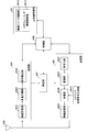
- FIG. 2 is a schematic block diagram showing the configuration of the base station device in this embodiment.
- the base station device includes an upper layer processing unit (upper layer processing step) 101, a control unit (control step) 102, a transmission unit (transmission step) 103, a reception unit (reception step) 104, and a transmission/reception antenna. 105 and a measuring unit (measuring step) 106.
- the upper layer processing unit 101 includes a radio resource control unit (radio resource control step) 1011 and a scheduling unit (scheduling step) 1012.
- the transmission unit 103 includes a coding unit (coding step) 1031, a modulation unit (modulation step) 1032, a downlink reference signal generation unit (downlink reference signal generation step) 1033, a multiplexing unit (multiplexing step) 1034, a radio.
- a transmitter (wireless transmission step) 1035 is included.
- the receiving unit 104 includes a wireless receiving unit (wireless receiving step) 1041, a demultiplexing unit (demultiplexing step) 1042, a demodulating unit (demodulating step) 1043, and a decoding unit (decoding step) 1044.
- the upper layer processing unit 101 is a medium access control (Medium Access Control: MAC) layer, a packet data integration protocol (Packet Data Convergence Protocol: PDCP) layer, a radio link control (Radio Link Control: RLC) layer, a radio resource control (Radio). Resource Control:RRC) layer processing. Further, upper layer processing section 101 generates information necessary for controlling transmitting section 103 and receiving section 104 and outputs it to control section 102.
- Medium Access Control: MAC Medium Access Control
- PDCP Packet Data Convergence Protocol
- RLC Radio Link Control
- Radio Radio Resource Control
- the upper layer processing unit 101 receives information about the terminal device such as the function (UE capability) of the terminal device from the terminal device. In other words, the terminal device transmits its own function to the base station device as an upper layer signal.
- the information about the terminal device includes information indicating whether the terminal device supports a predetermined function, or information indicating that the terminal device has introduced and tested a predetermined function.
- whether or not a given function is supported includes whether or not the introduction and testing of the given function have been completed.
- the terminal device transmits information (parameter) indicating whether or not the predetermined function is supported.
- the terminal device does not transmit information (parameter) indicating whether or not the predetermined function is supported. That is, whether or not the predetermined function is supported is notified by whether or not information (parameter) indicating whether or not the predetermined function is supported is transmitted.
- Information (parameter) indicating whether or not a predetermined function is supported may be notified using 1 bit of 1 or 0.
- the radio resource control unit 1011 generates downlink data (transport block), system information, RRC message, MAC CE, or the like arranged on the downlink PDSCH, or acquires from the upper node. Radio resource control section 1011 outputs downlink data to transmission section 103 and outputs other information to control section 102.
- the wireless resource control unit 1011 also manages various setting information of the terminal device.
- the scheduling unit 1012 determines frequencies and subframes to which physical channels (PDSCH and PUSCH) are assigned, coding rates and modulation schemes (or MCS) of physical channels (PDSCH and PUSCH), transmission power, and the like.
- the scheduling unit 1012 outputs the decided information to the control unit 102.
- the scheduling unit 1012 generates information used for scheduling the physical channels (PDSCH and PUSCH) based on the scheduling result.
- the scheduling unit 1012 outputs the generated information to the control unit 102.
- the control unit 102 generates a control signal for controlling the transmission unit 103 and the reception unit 104 based on the information input from the upper layer processing unit 101.
- the control unit 102 generates downlink control information based on the information input from the upper layer processing unit 101, and outputs the downlink control information to the transmission unit 103.
- the transmission unit 103 generates a downlink reference signal according to the control signal input from the control unit 102, and encodes the HARQ indicator, the downlink control information, and the downlink data input from the higher layer processing unit 101. Then, the signal is modulated, the PHICH, PDCCH, EPDCCH, PDSCH, and the downlink reference signal are multiplexed, and the signal is transmitted to the terminal device 2A via the transmission/reception antenna 105.
- the coding unit 1031 performs block coding, convolutional coding, turbo coding, LDPC (Low Density Parity Check: Low density) on the HARQ indicator, the downlink control information, and the downlink data input from the higher layer processing unit 101.
- encoding is performed using a predetermined encoding method such as parity check) encoding or Polar encoding, or encoding is performed using an encoding method determined by the radio resource control unit 1011.
- the modulation unit 1032 determines the coded bits input from the coding unit 1031 in advance with BPSK (Binary Phase Shift Keying), QPSK (quadrature Phase Shift Keying), 16QAM (quadrature amplitude modulation), 64QAM, 256QAM, etc. Alternatively, it is modulated by the modulation method determined by the radio resource control unit 1011.
- the downlink reference signal generation unit 1033 refers to a sequence known to the terminal device 2A, which is obtained by a predetermined rule based on a physical cell identifier (PCI, cell ID) for identifying the base station device 1A. Generate as a signal.
- PCI physical cell identifier
- the multiplexing unit 1034 multiplexes the modulated modulation symbol of each channel, the generated downlink reference signal, and the downlink control information. That is, multiplexing section 1034 arranges the modulated symbols of each modulated channel, the generated downlink reference signal, and downlink control information in resource elements.
- the wireless transmission unit 1035 generates an OFDM symbol by performing an Inverse Fast Fourier Transform (IFFT) on the multiplexed modulation symbols and the like, and adds a cyclic prefix (cyclic prefix: CP) to the OFDM symbol to base it.
- IFFT Inverse Fast Fourier Transform
- CP cyclic prefix
- the reception unit 104 separates, demodulates, and decodes the reception signal received from the terminal device 2A via the transmission/reception antenna 105 according to the control signal input from the control unit 102, and outputs the decoded information to the upper layer processing unit 101. ..
- the wireless reception unit 1041 down-converts an uplink signal received via the transmission/reception antenna 105 into a baseband signal, removes unnecessary frequency components, and amplifies so that the signal level is appropriately maintained.
- the level is controlled, quadrature demodulation is performed based on the in-phase component and the quadrature component of the received signal, and the quadrature-demodulated analog signal is converted into a digital signal.
- the wireless reception unit 1041 removes the portion corresponding to the CP from the converted digital signal.
- the wireless reception unit 1041 performs a fast Fourier transform (FFT) on the signal from which the CP is removed, extracts a frequency domain signal, and outputs the signal to the demultiplexing unit 1042.
- FFT fast Fourier transform
- the demultiplexing unit 1042 separates the signal input from the wireless reception unit 1041 into signals such as PUCCH, PUSCH, and uplink reference signal. Note that this separation is performed based on the radio resource allocation information included in the uplink grant that the base station device 1A has previously determined by the radio resource control unit 1011 and has notified each terminal device 2A.
- the demultiplexing unit 1042 compensates the propagation paths of PUCCH and PUSCH. Also, the demultiplexing unit 1042 separates the uplink reference signal.
- the demodulation unit 1043 performs inverse discrete Fourier transform (Inverse Discrete Fourier Transform: IDFT) on the PUSCH, obtains a modulation symbol, and for each of the PUCCH and PUSCH modulation symbols, BPSK, QPSK, 16QAM, 64QAM, 256QAM, and the like in advance.
- IDFT inverse discrete Fourier transform
- the received signal is demodulated by using the modulation method which is set or which the terminal apparatus has previously notified to the terminal apparatus 2A by the uplink grant.
- the decoding unit 1044 uses the coded bits of the demodulated PUCCH and PUSCH at a coding rate of a predetermined coding method, a predetermined coding rate, or a coding rate that the apparatus itself notifies the terminal apparatus 2A in advance by an uplink grant. Decoding is performed, and the decoded uplink data and uplink control information are output to upper layer processing section 101. When PUSCH is retransmitted, decoding section 1044 performs decoding using the coded bits held in the HARQ buffer input from upper layer processing section 101 and the demodulated coded bits.
- the measuring unit 106 observes the received signal and obtains various measured values such as RSRP/RSRQ/RSSI.
- the measurement unit 106 also obtains received power, reception quality, and a suitable SRS resource index from the SRS transmitted from the terminal device.
- FIG. 3 is a schematic block diagram showing the configuration of the terminal device according to the present embodiment.
- the terminal device includes an upper layer processing unit (upper layer processing step) 201, a control unit (control step) 202, a transmission unit (transmission step) 203, a reception unit (reception step) 204, and a measurement unit ( A measurement step) 205 and a transmission/reception antenna 206 are included.
- the upper layer processing unit 201 is configured to include a radio resource control unit (radio resource control step) 2011 and a scheduling information interpretation unit (scheduling information interpretation step) 2012.
- the transmission unit 203 includes a coding unit (coding step) 2031, a modulation unit (modulation step) 2032, an uplink reference signal generation unit (uplink reference signal generation step) 2033, a multiplexing unit (multiplexing step) 2034, and a radio.
- a transmitter (wireless transmission step) 2035 is included.
- the receiving unit 204 includes a wireless receiving unit (wireless receiving step) 2041, a demultiplexing unit (demultiplexing step) 2042, and a signal detecting unit (signal detecting step) 2043.
- the upper layer processing unit 201 outputs the uplink data (transport block) generated by a user operation or the like to the transmitting unit 203.
- the upper layer processing unit 201 is a medium access control (Medium Access Control: MAC) layer, a packet data integration protocol (Packet Data Convergence Protocol: PDCP) layer, a radio link control (Radio Link Control: RLC) layer, a radio resource control. (Radio Resource Control:RRC) Layer processing is performed.
- Medium Access Control: MAC Medium Access Control
- PDCP Packet Data Convergence Protocol
- RLC Radio Link Control
- RRC Radio Resource Control
- the upper layer processing unit 201 outputs information indicating the function of the terminal device supported by the own terminal device to the transmitting unit 203.
- the wireless resource control unit 2011 manages various setting information of its own terminal device. In addition, the radio resource control unit 2011 generates information arranged in each uplink channel and outputs the information to the transmission unit 203.
- the wireless resource control unit 2011 acquires the setting information transmitted from the base station device and outputs it to the control unit 202.
- the scheduling information interpretation unit 2012 interprets the downlink control information received via the reception unit 204 and determines the scheduling information.
- the scheduling information interpretation unit 2012 also generates control information for controlling the reception unit 204 and the transmission unit 203 based on the scheduling information, and outputs the control information to the control unit 202.
- the control unit 202 generates a control signal for controlling the receiving unit 204, the measuring unit 205, and the transmitting unit 203 based on the information input from the upper layer processing unit 201.
- the control unit 202 outputs the generated control signal to the receiving unit 204, the measuring unit 205, and the transmitting unit 203 to control the receiving unit 204 and the transmitting unit 203.
- the control unit 202 controls the transmission unit 203 to transmit the CSI/RSRP/RSRQ/RSSI generated by the measurement unit 205 to the base station device.
- the reception unit 204 separates, demodulates, and decodes the reception signal received from the base station device via the transmission/reception antenna 206 according to the control signal input from the control unit 202, and outputs the decoded information to the upper layer processing unit 201. To do.
- the wireless reception unit 2041 down-converts the downlink signal received via the transmission/reception antenna 206 into a baseband signal, removes unnecessary frequency components, and an amplification level so that the signal level is appropriately maintained. Quadrature demodulation based on the in-phase component and the quadrature component of the received signal, and the quadrature-demodulated analog signal is converted into a digital signal.
- the wireless reception unit 2041 removes a portion corresponding to the CP from the converted digital signal, performs a fast Fourier transform on the signal from which the CP is removed, and extracts a signal in the frequency domain.
- Demultiplexing section 2042 separates the extracted signal into PHICH, PDCCH, EPDCCH, PDSCH, and downlink reference signal. Further, demultiplexing section 2042 performs channel compensation for PHICH, PDCCH, and EPDCCH based on the channel estimation value of the desired signal obtained from the channel measurement, detects downlink control information, and causes control section 202 to control. Output. Further, the control unit 202 outputs the PDSCH and the channel estimation value of the desired signal to the signal detection unit 2043.
- the signal detection unit 2043 demodulates and decodes using the PDSCH and the channel estimation value, and outputs it to the upper layer processing unit 201. Further, when removing or suppressing the interference signal, the signal detection unit 2043 obtains the channel estimation value of the interference channel using the parameter of the interference signal, and demodulates and decodes the PDSCH.
- the measurement unit 205 performs various measurements such as CSI measurement, RRM (Radio Resource Management) measurement, and RLM (Radio Link Monitoring) measurement, and obtains CSI/RSRP/RSRQ/RSSI.
- CSI measurement CSI measurement
- RRM Radio Resource Management
- RLM Radio Link Monitoring
- the transmission unit 203 generates an uplink reference signal according to the control signal input from the control unit 202, encodes and modulates the uplink data (transport block) input from the higher layer processing unit 201, and PUCCH,
- the PUSCH and the generated uplink reference signal are multiplexed and transmitted to the base station apparatus via the transmission/reception antenna 206.
- the coding unit 2031 performs coding such as convolutional coding, block coding, turbo coding, LDPC coding, and Polar coding on the uplink control information or uplink data input from the upper layer processing unit 201.
- the modulation unit 2032 modulates the coded bits input from the coding unit 2031 by the modulation method notified by the downlink control information such as BPSK, QPSK, 16QAM, 64QAM, or a predetermined modulation method for each channel. ..
- the uplink reference signal generation unit 2033 uses a physical cell identifier (referred to as physical cell identity: PCI, Cell ID, etc.) for identifying the base station device, a bandwidth in which the uplink reference signal is arranged, and an uplink grant.
- a sequence determined by a predetermined rule (expression) is generated based on the notified cyclic shift, the value of the parameter for generating the DMRS sequence, and the like.
- the multiplexing unit 2034 multiplexes the PUCCH and PUSCH signals and the generated uplink reference signal for each transmission antenna port. That is, multiplexing section 2034 arranges the PUCCH and PUSCH signals and the generated uplink reference signal in resource elements for each transmission antenna port.
- the wireless transmission unit 2035 performs an inverse fast Fourier transform (Inverse Fast Fourier Transform: IFFT) on the multiplexed signal, performs OFDM modulation, generates an OFDMA symbol, and adds a CP to the generated OFDMA symbol, Generates a baseband digital signal, converts the baseband digital signal to an analog signal, removes excess frequency components, converts to a carrier frequency by up-conversion, power-amplifies, outputs to the transmitting/receiving antenna 206, and transmits.
- IFFT inverse Fast Fourier transform
- the terminal device can perform not only the OFDMA method but also the SC-FDMA method.
- ultra-high-capacity communication such as ultra-high-definition video transmission
- ultra-wide band transmission utilizing high frequency band is desired.
- For transmission in the high frequency band it is necessary to compensate for path loss, and beamforming is important.
- an ultra-dense network (Ultra-dense network) in which base station devices are densely arranged network) is valid.
- the base station devices are arranged at a high density, although the SNR (Signal to noise power ratio) is greatly improved, strong interference may occur due to beamforming. Therefore, in order to realize super-high-capacity communication for all terminal devices in a limited area, interference control (avoidance, suppression, removal) considering beamforming and/or cooperative communication of a plurality of base stations is required. Will be required.
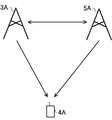
- FIG. 4 shows an example of a downlink communication system according to this embodiment.
- the communication system shown in FIG. 4 includes a base station device 3A, a base station device 5A, and a terminal device 4A.
- the terminal device 4A can use the base station device 3A and/or the base station device 5A as a serving cell.
- the base station device 3A or the base station device 5A is provided with a large number of antennas, a large number of antennas are provided in a plurality of subarrays (panel, subpanel, transmission antenna port, transmission antenna group, reception antenna port, reception antenna group, antenna group). , Antenna port group), and transmit/receive beamforming can be applied to each subarray.
- each sub-array can include a communication device, and the configuration of the communication device is the same as that of the base station device shown in FIG. 2 unless otherwise specified.
- the terminal device 4A includes a plurality of antennas
- the terminal device 4A can perform transmission or reception by beamforming.
- a large number of antennas are provided in a plurality of subarrays (panel, subpanel, transmission antenna port, transmission antenna group, reception antenna port, reception antenna group, antenna group, antenna port group).
- different transmit/receive beamforming can be applied to each subarray.
- Each sub-array can include a communication device, and the configuration of the communication device is the same as the configuration of the terminal device shown in FIG. 3 unless otherwise specified.
- the base station device 3A and the base station device 5A are also simply referred to as base station devices.
- the terminal device 4A is also simply referred to as a terminal device.
- a synchronization signal is used to determine a suitable transmission beam for the base station device and a suitable reception beam for the terminal device.
- the base station device transmits a synchronization signal block composed of PSS, PBCH, and SSS. It should be noted that within the synchronization signal block burst set period set by the base station apparatus, one or more synchronization signal blocks are transmitted in the time domain, and a time index is set for each synchronization signal block.
- the terminal device determines that the sync signal block having the same time index within the sync signal block burst set period is a delay spread, a Doppler spread, a Doppler shift, an average gain, an average delay, a spatial reception parameter, and/or a spatial transmission parameter.
- the spatial reception parameters are, for example, spatial correlation of channels, angle of arrival (angle of arrival), reception beam direction, and the like.
- the spatial transmission parameters are, for example, channel spatial correlation, transmission angle (Angle Departure), transmission beam direction, and the like. That is, the terminal device can assume that within the synchronization signal block burst set period, synchronization signal blocks with the same time index are transmitted with the same transmission beam, and synchronization signal blocks with different time indexes are transmitted with different beams.
- the terminal device can know the transmission beam suitable for the terminal device. Further, the terminal device can obtain a reception beam suitable for the terminal device by using the synchronization signal blocks having the same time index in different synchronization signal block burst set periods. Therefore, the terminal device can associate the time index of the synchronization signal block with the reception beam direction and/or the sub-array. When the terminal device includes a plurality of sub-arrays, different sub-arrays may be used when connecting to different cells.
- the time index of the synchronization signal block is also referred to as SSB index or SSB resource indicator (SSBRI).
- QCL types there are four QCL types that indicate the QCL status.
- the four QCL types are called QCL type A, QCL type B, QCL type C, and QCL type D, respectively.
- QCL type A is a relationship (state) in which Doppler shift, Doppler spread, average delay, and delay spread become QCL.
- QCL type B is a relationship (state) in which Doppler shift and Doppler spread are QCL.
- the QCL type C is a relationship (state) in which the average delay and the Doppler shift are QCL.
- the QCL type D is a relationship (state) in which the spatial reception parameter is QCL.
- the above four QCL types can be combined with each other. For example, QCL type A+QCL type D, QCL type B+QCL type D, and the like.
- one or more TCI (Transmit Configuration Indicator) states are set by the signal of the upper layer.
- One TCI state can set the QCL type with one or a plurality of downlink signals in a certain cell (cell ID) and a certain partial band (BWP-ID).
- the downlink signal includes CSI-RS and SSB.
- the TCI state is set by the RRC message (signaling), and one or more of the set TCI states are activated/deactivated in the MAC layer.
- the TCI state can associate the QCL of the downlink signal with the DMRS of the PDSCH. For example, one or more of the TCI states activated by DCI are indicated and can be used for demodulation (decoding) of the associated PDSCH.
- the terminal device can know the reception beam direction (spatial reception filter) of the associated PDSCH. Therefore, the TCI can be said to be information related to the reception beam direction of the terminal device. Also, the TCI state can associate the QCL of the downlink signal with the DMRS of the PDCCH. From the one or more TCI states set by the RRC message (signaling), one TCI state is activated in the MAC layer as the TCI state for the PDCCH. This allows the terminal device to know the reception beam direction of PDCCH DMRS. The default PDCCH DMRS receive beam direction is associated with the SSB index at the time of initial access.
- CSI-RS can be used to determine a suitable transmission beam of the base station device and a suitable reception beam of the terminal device.
- the terminal device receives the CSI-RS with the resource set in the CSI resource setting, calculates the CSI or RSRP from the CSI-RS, and reports it to the base station device.
- the CSI-RS resource setting includes a plurality of CSI-RS resource settings and/or when resource repetition is OFF
- the terminal device receives the CSI-RS with the same reception beam on each CSI-RS resource, Calculate the CRI.
- the CRI indicates N preferred CSI-RS resources from the K CSI-RS resources. .. However, N is a positive integer less than K.
- the terminal device may report the CSI-RSRP measured by each CSI-RS resource to the base station device in order to indicate which CSI-RS resource has good quality. it can.
- the base station apparatus performs beamforming (precoding) of CSI-RSs in different beam directions with a plurality of set CSI-RS resources and transmits the CSI-RSs, the base station apparatus suitable for the terminal apparatus according to the CRI reported from the terminal apparatus. It is possible to know the transmission beam direction of.
- the preferred reception beam direction of the terminal device can be determined by using the CSI-RS resource in which the transmission beam of the base station device is fixed.
- the terminal apparatus receives CSI-RS resources received in different reception beam directions in each CSI-RS resource.
- a suitable reception beam direction can be obtained from RS.
- the terminal device may report CSI-RSRP after determining a suitable reception beam direction.
- the terminal device can select a suitable sub-array when obtaining a suitable reception beam direction.
- the preferred reception beam direction of the terminal device may be associated with the CRI (or CSI-RS resource ID).
- the base station device can fix the transmission beam with the CSI-RS resource associated with each CRI (or CSI-RS resource ID).
- the terminal device can determine a suitable reception beam direction for each CRI (or CSI-RS resource ID).
- the base station apparatus can associate the downlink signal/channel with the CRI (or CSI-RS resource ID) and transmit.
- the terminal device must receive with the receive beam associated with the CRI.
- different CSI-RSs can be transmitted by different base station apparatuses in the set plurality of CSI-RS resources. In this case, the network side can know from which base station device the communication quality is good by the CRI (or CSI-RS resource ID).
- the terminal device when the terminal device includes a plurality of sub-arrays, the sub-arrays can be received at the same timing. Therefore, if the base station apparatus associates and transmits a CRI (or CSI-RS resource ID) to each of a plurality of layers (codewords, transport blocks) in downlink control information or the like, the terminal apparatus can transmit each CRI (or CSI). -Multiple layers can be received by using a sub-array corresponding to (RS resource ID) and a reception beam. However, when using an analog beam, when one sub-array uses one reception beam direction at the same timing, two CRIs (or CSI-RS resource IDs) corresponding to one sub-array of the terminal device are simultaneously set.
- the terminal device may not be able to receive with multiple receive beams.
- the base station device divides a plurality of set CSI-RS resources into groups, and within the group, the CRI is obtained using the same subarray. If different subarrays are used between groups, the base station device can know a plurality of CRIs that can be set at the same timing.
- the group of CSI-RS resources may be CSI-RS resources set by CSI resource setting or CSI-RS resource set setting.
- the CRI (or CSI-RS resource ID) that can be set at the same timing may be QCL.
- the terminal device can transmit the CRI (or CSI-RS resource ID) in association with the QCL information.
- the QCL information is information on the QCL for a given antenna port, a given signal, or a given channel.
- the long-term characteristics of the channel carrying the symbols on one antenna port can be inferred from the channel carrying the symbols on the other antenna port, then those antenna ports are QCL. Is called.
- the long-term characteristic includes delay spread, Doppler spread, Doppler shift, average gain, average delay, spatial reception parameter, and/or spatial transmission parameter. For example, when two antenna ports are QCL, the terminal device can consider that the long-term characteristics in those antenna ports are the same.
- the base station device has the same CRI that is QCL regarding spatial reception parameters. It is possible to set the CRI that is not QCL with respect to the spatial reception parameter to the same timing without setting the timing.
- the base station apparatus may request CSI for each sub-array of the terminal apparatus. In this case, the terminal device reports the CSI for each sub array.
- the terminal device reports a plurality of CRIs to the base station device, it may report only the CRIs that are not QCL.
- a codebook in which predetermined precoding (beamforming) matrix (vector) candidates are defined is used.
- the base station apparatus transmits CSI-RS, the terminal apparatus obtains a suitable precoding (beamforming) matrix from the codebook, and reports it to the base station apparatus as PMI.
- the base station apparatus can know the transmission beam direction suitable for the terminal apparatus.
- the codebook includes a precoding (beamforming) matrix for synthesizing antenna ports and a precoding (beamforming) matrix for selecting antenna ports. When a codebook that selects antenna ports is used, the base station apparatus can use different transmission beam directions for each antenna port.
- the base station device can know a suitable transmission beam direction.
- the preferred receive beam of the terminal device may be the receive beam direction associated with the CRI (or CSI-RS resource ID), or the preferred receive beam direction may be determined again.
- a codebook for selecting an antenna port is used and a preferred receive beam direction of a terminal device is a receive beam direction associated with a CRI (or CSI-RS resource ID)
- a receive beam direction for receiving CSI-RS Is preferably received in the receive beam direction associated with the CRI (or CSI-RS resource ID). Note that the terminal device can associate the PMI and the receive beam direction even when using the receive beam direction associated with the CRI (or CSI-RS resource ID).
- each antenna port may be transmitted from a different base station apparatus (cell).
- the base station device can know with which base station device (cell) the communication quality is suitable.
- the antenna ports of different base station devices (cells) may not be QCL.
- Collaborative communication between a plurality of base station devices (transmission/reception points) includes, for example, DPS (Dynamic Point Selection; dynamic point selection) that dynamically switches suitable base station devices (transmission/reception points), and a plurality of base station devices (transmission/reception points) From JT (Joint Transmission) for transmitting the same or different data signal from the same.
- DPS Dynamic Point Selection
- JT Joint Transmission
- the terminal device may communicate using a plurality of subarrays.
- the terminal device 4A can use the sub array 1 when communicating with the base station device 3A, and can use the sub array 2 when communicating with the base station device 5A.
- the terminal device performs cooperative communication with the plurality of base station devices, there is a possibility that the plurality of subarrays may be dynamically switched, or the plurality of subarrays may transmit/receive at the same timing. At this time, it is desirable that the terminal device 4A and the base station device 3A/5A share information regarding the sub-array of the terminal device used for communication.
- the terminal device can include CSI setting information in the CSI report.
- the CSI setting information can include information indicating a sub array.
- the terminal device can transmit a CSI report including a CRI (or CSI-RS resource ID) and an index indicating a subarray.
- the base station apparatus can associate the transmission beam direction with the subarray of the terminal apparatus.
- the terminal device can transmit a CRI report including a plurality of CRIs (or CSI-RS resource IDs).
- the station device can associate the CRI (or CSI-RS resource ID) with the index indicating the sub array.
- the terminal apparatus can jointly code the CRI (or CSI-RS resource ID) and the index indicating the subarray to transmit the CRI report in order to reduce the control information.
- N is an integer of 2 or more bits indicating CRI
- one bit indicates sub-array 1 or sub-array 2
- the remaining bits indicate CRI.
- the terminal device may detect CRI from some CSI-RS resources if the number of CSI-RS resources indicated by the CSI resource setting is larger than the number capable of expressing CRI. Can be asked.
- the terminal device may detect CRI from some CSI-RS resources if the number of CSI-RS resources indicated by the CSI resource setting is larger than the number capable of expressing CRI. Can be asked.
- the base station device will be set for each sub-array of the terminal. Can know the CSI.
- the CSI setting information can also include CSI measurement setting information.
- the setting information for CSI measurement may be measurement link setting or other setting information. This allows the terminal device to associate the CSI measurement setting information with the sub-array and/or receive beam direction.
- the CSI-RS setting for channel measurement transmitted by the base station device 3A is referred to as resource setting 1
- the CSI-RS setting for channel measurement transmitted by the base station device 5A is referred to as resource setting 2.
- the setting information 1 can be the resource setting 1
- the setting information 2 can be the resource setting 2
- the setting information 3 can be the resource setting 1 and the resource setting 2.
- each setting information may include the setting of the interference measurement resource. If the CSI measurement is performed based on the setting information 1, the terminal device can measure the CSI with the CSI-RS transmitted from the base station device 3A. If the CSI measurement is performed based on the setting information 2, the terminal device can measure the CSI transmitted from the base station device 5A. If the CSI measurement is performed based on the setting information 3, the terminal device can measure the CSI with the CSI-RS transmitted from the base station device 3A and the base station device 5A. The terminal device can associate each of the setting information 1 to 3 with the sub-array and/or the reception beam direction used for the CSI measurement.
- the base station apparatus can instruct the preferred sub-array and/or the reception beam direction used by the terminal apparatus by instructing the setting information 1 to 3.
- the terminal device obtains the CSI for the resource setting 1 and/or the CSI for the resource setting 2.
- the terminal device can associate the sub-array and/or the reception beam direction with each of the resource setting 1 and/or the resource setting 2.
- resource setting 1 and/or resource setting 2 can be associated with a codeword (transport block).
- the CSI for resource setting 1 can be the CSI for codeword 1 (transport block 1) and the CSI for resource setting 2 can be the CSI for codeword 2 (transport block 2).
- the terminal device can also obtain one CSI in consideration of the resource setting 1 and the resource setting 2.
- the terminal device can associate the sub-array and/or the reception beam direction with respect to each of resource setting 1 and resource setting 2 even when obtaining one CSI.
- the CSI setting information includes, when a plurality of resource settings are set (for example, when the above setting information 3 is set), the CSI includes one CRI or a CRI for each of the plurality of resource settings. Information indicating whether to include may be included.
- the CSI setting information may include a resource setting ID for which the CRI is calculated. The CSI setting information allows the base station apparatus to know under what assumption the terminal apparatus calculated the CSI or which resource setting the reception quality was good.
- the base station device can send a CSI request requesting a CSI report to the terminal device.
- the CSI request may include reporting CSI in one subarray or reporting CSI in multiple subarrays.
- the terminal device transmits a CSI report that does not include an index indicating the subarray.
- the terminal device transmits a CSI report including an index indicating the subarray.
- the base station device can instruct the sub array that the terminal device calculates the CSI by using the index indicating the sub array or the resource setting ID. In this case, the terminal device calculates CSI with the subarray instructed by the base station device.
- the base station device can include the CSI measurement setting information in the CSI request for transmission.
- the terminal device obtains the CSI based on the CSI measurement setting information.
- the terminal device reports the CSI to the base station device, but does not have to report the CSI measurement setting information.
- the terminal device and the base station device can newly set a virtual antenna port in order to select a suitable subarray.
- the virtual antenna ports are each associated with a physical subarray and/or receive beam.
- the base station device can notify the terminal device of the virtual antenna port, and the terminal device can select a subarray for receiving the PDSCH.
- QCL can be set for the virtual antenna port.
- the base station device can notify the plurality of terminal devices of the virtual antenna port. When the notified virtual antenna port is QCL, the terminal device can receive the associated PDSCH by using one subarray, and the notified virtual antenna port is QCL. If not, two or more sub-arrays can be used to receive the associated PDSCH.
- the virtual antenna port can be associated with any one or a plurality of CSI-RS resources, DMRS resources, and SRS resources.
- the base station device By setting the virtual antenna port, the base station device provides a sub-array when the terminal device sends an RS in any one or more of CSI-RS resource, DMRS resource, and SRS resource. Can be set.
- the terminal device When a plurality of base station devices perform coordinated communication, it is desirable that the terminal device receives in a sub-array and/or receive beam direction suitable for the PDSCH transmitted by each base station device. Therefore, the base station apparatus transmits information that enables the terminal apparatus to receive in a suitable sub-array and/or receive beam direction.
- the base station apparatus can include the CSI setting information or the information indicating the CSI setting information in the downlink control information for transmission.
- the terminal device Upon receiving the CSI setting information, the terminal device can receive the CSI setting information in the sub-array and/or the receiving beam direction associated with the CSI setting information.
- the base station device can transmit information indicating a sub array and/or a reception beam direction as CSI setting information.
- the CSI setting information may be transmitted in a predetermined DCI format.
- the information indicating the receiving beam direction may be the CRI (or CSI-RS resource ID), PMI, and time index of the synchronization signal block.
- the terminal device can know the suitable sub-array and/or the reception beam direction from the received DCI.
- the information indicating the sub array is represented by 1 bit or 2 bits. When the information indicating the sub array is indicated by 1 bit, the base station apparatus can indicate the sub array 1 or the sub array 2 to the terminal apparatus by "0" or "1".
- the base station apparatus can switch the sub-array and instruct the terminal apparatus to receive the sub-array.
- the base station apparatus can indicate the subarray of the terminal apparatus by transmitting the DCI including the resource setting ID.
- the base station device can transmit CSI measurement setting information as CSI setting information.
- the terminal device can receive the PDSCH in the sub-array and/or the reception beam direction associated with the CSI fed back in the setting information of the received CSI measurement.
- the CSI measurement setting information indicates the setting information 1 or the setting information 2
- the CSI setting information indicates that PDSCH transmission is associated with one resource setting information.
- the CSI measurement setting information indicates the setting information 3
- the CSI setting information indicates that PDSCH transmission is associated with a plurality of resource setting information.
- the CSI setting information may be associated with a parameter (field) included in the DCI such as a scrambling identity (SCID) of DMRS.
- SCID scrambling identity
- the base station device can set the association between the SCID and the setting information of the CSI measurement.
- the terminal device can refer to the CSI measurement setting information from the SCID included in the DCI, and receive the PDSCH in the sub-array and/or the receiving beam direction associated with the CSI measurement setting information.
- the base station device can set two DMRS antenna port groups. These two DMRS port groups are also referred to as DMRS port group 1 (first DMRS port group) and DMRS port group 2 (second DMRS port group).
- the antenna ports in the DMRS antenna port group are QCL, and the antenna ports between the DMRS antenna port groups are not QCL. Therefore, if the DMRS antenna port group and the subarray of the terminal device are associated with each other, the base station device can instruct the subarray of the terminal device by the DMRS antenna port number included in the DCI. For example, when the DMRS antenna port number included in DCI is included in one DMRS antenna port group, the terminal device receives in one subarray corresponding to the DMRS antenna port group.
- the terminal device receives the terminal device with two subarrays.
- One DMRS antenna port group may be associated with one codeword (transport block).
- the relationship between the DMRS antenna port group and the codeword (transport block) index may be predetermined or may be instructed by the base station apparatus.
- the DMRS antenna port group is associated with the resource setting ID or the CSI-RS resource, the DMRS antenna ports included in the DCI
- the terminal device can specify the resource setting ID or the CSI-RS resource, and can know the sub-array and/or the reception beam direction.
- the base station device can set the DMRS antenna port group and the CSI setting information in association with each other.
- the CSI setting information includes the setting information for the CSI measurement and the setting information for the CSI measurement indicates the setting information 3
- the terminal device corresponds to the resource setting 1 in the case of the DMRS antenna port included in the DMRS antenna port group 1.
- the demodulation is performed in the sub array and/or the reception beam direction, and when the DMRS antenna port included in the DMRS antenna port group 2 is demodulated in the sub array and/or the reception beam direction corresponding to the resource setting 2.
- the terminal device when the report amount is set to CRI/RSRP or SSBRI/RSRP, and the group-based beam reporting is set to OFF, the terminal device is different in one report 1, 2 or Report 4 different CRIs or SSBRIs.
- the report amount when the report amount is set to CRI/RSRP or SSBRI/RSRP in the CSI report setting and the group-based beam reporting is set to ON, the terminal device uses two different CRIs or one in one report. Report SSBRI.
- two CSI-RS resources or two SSBs can be received simultaneously by one spatial domain reception filter or a plurality of spatial domain reception filters.
- the terminal device receives the reception filter (panel, sub array) in one spatial region.
- the two CSI-RS resources are called a first CSI-RS resource and a second CSI-RS resource, respectively.
- the CRI indicating the first CSI-RS resource is also referred to as a first CRI
- the CRI indicating the second CSI-RS resource is also referred to as a second CRI.
- the RI obtained by the first CSI-RS resource is also called a first RI
- the RI obtained by the second CSI-RS resource is also called a second RI.
- the CSI reported by the terminal device may change depending on whether the sum of the first RI and the second RI is 4 or less or greater than 4.
- the CQI obtained by considering both the first CSI-RS and the second CSI-RS is obtained.
- the terminal device obtains the CSI in consideration of the first CRI, the second CRI, the first RI, the second RI, and both the first CSI-RS and the second CSI-RS. Report the CQI.
- the terminal device reports the first CRI, the second CRI, the first RI, the second RI, the first CQI, and the second CQI as the CSI.
- the terminal device may receive a reception filter or a plurality of reception filters in one spatial region.
- CSI is obtained based on two CSI-RS resources that can be simultaneously received by the spatial domain reception filter.
- the PMI for the first CSI-RS resource is also referred to as a first PMI
- the PMI for the second CSI-RS resource is also referred to as a second PMI.
- the first PMI and the second PMI may be obtained in consideration of both the first CRI and the second CRI. In this case, the first PMI and the second PMI considering mutual interference are obtained.
- PMI is divided into PMI-1 and PMI-2 when CSI-RS has four or more antenna ports.
- PMI-1 is wideband information, and indicates a codebook index obtained based on at least N1 and N2.
- the number of antenna ports of CSI-RS is represented by 2N1N2.
- N1 and N2 are both integers of 1 or more
- N1 represents the number of antenna ports in the first dimension (eg, horizontal direction)
- N2 represents the number of antenna ports in the second dimension (eg, vertical direction).
- the number of polarization antennas is two.
- PMI-1 includes one or more pieces of information depending on the values of N1 and N2 and RI (number of layers).
- the PMI-2 is wideband or subband information and indicates at least phase rotation.
- the PMI-1 and PMI-2 obtained by the first CSI-RS resource are also referred to as the first PMI-1 and the first PMI-2, respectively.
- PMI-1 and PMI-2 obtained by the second CSI-RS resource are also referred to as a second PMI-1 and a second PMI-2, respectively.
- the report amount may be set to CRI, RI, PMI-1, CQI.
- the CRI, RI, and CQI are the same as when the report amount is set to CRI, RI, and CQI. Therefore, when the total of the first RI and the second RI is 4 or less, the terminal device determines that the CSI is the first CRI, the second CRI, the first RI, the second RI, the first PMI.
- the CQI obtained by considering (PMI-1), the second PMI (PMI-1), and both the first CSI-RS and the second CSI-RS is reported.
- the terminal device determines that the CSI is the first CRI, the second CRI, the first RI, the second RI, and the first PMI.
- PMI-1), second PMI (PMI-1), first CQI, and second CQI are reported.
- the first RI and the second RI are equal to or smaller than the number of layers with a codeword number of 2, so the first RI is the same as the second RI. Same or smaller. That is, when the RI is reported, it is preferable that the first CRI and the second CRI have better reception power (RSRP)/reception quality (RSRQ) than the first CRI, and the first CRI or The second CRI is determined.
- RSRP reception power
- RSRQ rejection quality
- the terminal device may report the CSI of either the first CRI or the second CRI, for example, the one with the larger RI value. .. In addition, because of the above rule, the terminal device may report the total value of the first RI and the second RI without separately reporting the first RI and the second RI.
- the first CRI and the second CRI are set. Different CRIs may result in different codewords.
- the CQI, the first CQI and the second CQI are reported. However, the total of the first RI and the second RI is 8 or less, and the RI in one CRI is 4 or less.
- the base station apparatus may instruct the terminal apparatus.
- the difference may be 1 when the number of layers of codeword 1 and the number of layers of codeword 2 are different.
- the first RI is 2 and the second RI is 2.
- the sum of the first RI and the second RI is 3, the first RI is 1 and the second RI is 2.
- the sum of the first RI and the second RI is 2, the first RI is 1 and the second RI is 1.
- the CRI with the larger RI is set higher. That is, in the present embodiment, the second CRI has a higher priority than the second CRI.
- the CQI is reported by one of the CRIs
- the CQI obtained by the one CRI is reported even if the total of the first RI and the second RI is 4 or less.
- CSI When CSI is reported on PUSCH or subband CSI is reported on PUCCH, CSI is divided into two parts and reported.
- the two parts are also referred to as a first part (part 1, CSI part 1) and a second part (part 2, CSI part 2).
- the first part has a higher priority in CSI reporting than the second part.
- the first part is the sum of the first RI and the second RI (or the second RI), the second CRI, the CQI based on the first CRI and the second CRI. (Or the second CQI) is partially or entirely included.
- the second part includes a part or all of the first CRI, the first RI, the first CQI, the first PMI, and the second PMI.
- the first part includes the sum of the first RI and the second RI (or the second RI), the second CRI, or some or all of the second CQI.
- the second part includes a part or all of the first CRI, the first RI, the first CQI, the first PMI, and the second PMI.
- the CSI may be divided into three.
- the third part is also called the third part (part 3, CSI part 3).
- the third part has lower priority than the second part.
- the first part is the sum of the first RI and the second RI (or the second RI), the second CRI, the CQI based on the first CRI and the second CRI (or the second CQI). ) Is included in part or all.
- the second part includes part or all of the first CRI, the first RI, and the first CQI.
- the third part includes a part or all of the first PMI and the second PMI.
- the terminal device may report by dividing into two parts for each of the CSI based on the first CRI and the CSI based on the second CRI.
- the two parts of the CSI based on the first CRI are also called the first part 1 and the first part 2.
- the two parts of the CSI based on the second CRI are also called the second part 1 and the second part 2.
- the first part 1 includes a part or all of the first CRI, the first RI, and the first CQI.
- the first part 2 includes a first PMI.
- the second part 1 includes a part or all of the second CRI, the second RI, and the second CQI.
- the second part 2 also includes a second PMI.
- the CSI priority can be set higher in the order of the second part 1, the first part 1, the second part 2, and the first part 2.
- the terminal device will report a long-period (small change) CSI in the second CRI and the first CRI, and the base station device and the terminal device will report the minimum CSI for the first CRI and the second CRI. It is possible to communicate using limited parameters.
- the CSI priority can be set higher in the order of the second part 1, the second part 2, the first part 1, and the first part 2. At this time, the terminal device preferentially reports the complete CSI in the second CRI, so that the base station device and the terminal device can communicate using the detailed parameters regarding the second CRI.
- the terminal device selects the CSI based on the first CRI and the second CRI.
- Report information indicating that either or both of the based CSIs are reported.
- Information indicating that either or both of the CSI based on the first CRI and the CSI based on the second CRI are reported is included in the first part of the CSI.
- the information indicating that the CSI based on the first CRI and/or the CSI based on the second CRI is reported indicates whether or not the first CRI is included in the second part of the CSI. May be.
- DMRS setting type 1 (first DMRS setting type) or DMRS setting type 2 (second DMRS setting type) is set as the DMRS for PDSCH or PUSCH.
- DMRS setting type 1 supports up to 8 DMRS antenna ports
- DMRS setting type 2 supports up to 12 DMRS antenna ports.
- the DMRS is code division multiplexed (CDM) with an orthogonal cover code (OCC).
- the OCC has a maximum code length of 4, which has a length of 2 in the frequency direction and a length of 2 in the time direction.
- the front-loaded DMRS is arranged in one symbol or two symbols.
- Up to 4 DMRS antenna ports are CDMed in OCC.
- the 4DMRS antenna ports for CDM are also called CDM group (DMRS CDM group).
- DMRS setting type 1 has two CDM groups
- DMRS setting type 2 has three CDM groups.
- DMRSs of different CDM groups are arranged in orthogonal resources.
- the two DMRS setting type 1 CDM groups are also referred to as CDM group 0 (first CDM group) and CDM group 1 (second CDM group).
- CDM group 0 includes DMRS antenna ports 1000, 1001, 1004, 1005 and CDM group 1 includes DMRS antenna ports 1002, 1003, 1006, 1007.
- CDM group 0 includes DMRS antenna ports 1000, 1001, 1006, 1007
- CDM group 1 includes DMRS antenna ports 1002, 1003, 1008, 1009
- CDM group 2 includes DMRS antennas. Includes ports 1004, 1005, 1010, 1011.
- the CDM group related to DMRS is also referred to as DMRS CDM group.
- the DMRS antenna port number for PDSCH or PUSCH and the number of DMRS CDM groups without data are indicated by DCI.
- the terminal device can know the number of DMRS antenna ports from the number of instructed DMRS antenna port numbers.
- the number of DMRS CDM groups without data indicates that PDSCH is not arranged in the resource in which DMRS of the related CDM group is arranged.
- the referenced CDM groups without data is CDM group 0 and when the number of DMRS CDM groups without data is 2, the referenced CDM groups are CDM group 0 and CDM group 1. If the number of DMRS CDM groups with and without data is 3, the referenced CDM groups are CDM group 0, CDM group 1 and CDM group 2.
- the DMRS for PDSCH or PUSCH may have different power from the PDSCH.
- the base station apparatus spatially multiplexes the 4-layer PDSCH and transmits the PDSCH to each of the two terminal apparatuses. That is, the base station apparatus spatially multiplexes and transmits PDSCHs of 8 layers in total.
- the base station apparatus instructs the DMRS antenna port number of CDM group 0 to one terminal apparatus and the DMRS antenna port number of CDM group 1 to the other terminal apparatus.
- the base station device instructs the two terminal devices that the number of DMRS CDM groups without data is 2.
- the spatial multiplexing number of DMRS is 4, whereas the spatial multiplexing number of PDSCH is 8, and the power ratio (offset) between DMRS and PDSCH is doubled (3 dB different).
- the base station apparatus spatially multiplexes the 4-layer PDSCH and transmits it to each of the three terminal apparatuses. That is, the base station apparatus spatially multiplexes 12 layers of PDSCHs for transmission.
- the base station device instructs the DMRS antenna port numbers of CDM group 0, CDM group 1 and CDM group 2 to the three terminal devices, respectively.
- the base station device instructs the three terminal devices that the number of DMRS CDM groups without data is three.
- the spatial multiplexing number of DMRS is 4, whereas the spatial multiplexing number of PDSCH is 12, and the power ratio of DMRS and PDSCH is tripled (4.77 dB different). Therefore, the base station device or the terminal device transmits the DMRS and PDSCH in consideration of the power ratio of DMRS and PDSCH that is the number of CDM groups.
- the base station apparatus or terminal apparatus demodulates (decodes) PDSCH in consideration of the power ratio of DMRS and PDSCH that is the number of CDM groups. In the case of SU-MIMO (Single user MIMO) transmission in which the number of spatially multiplexed signals is large, the power ratio between DMRS and PDSCH which is the number of CDM groups is also considered.
- SU-MIMO Single user MIMO
- the power ratio of DMRS and PDSCH may be different from the above.
- each base station device spatially multiplexes and transmits a 4-layer PDSCH.
- one base station device or two base station devices instructs the number of DMRS CDM groups without data to be 2.
- the power ratio of DMRS and PDSCH is 1 (0 dB), and the power ratio of DMRS and PDSCH is You don't have to consider it.
- the terminal device needs to know (determine) whether or not to demodulate (decode) PDSCH in consideration of the power ratio between DMRS and PDSCH.
- each base station device may reduce the power of PDSCH according to the number of DMRS CDM groups without data, but In this case, reliability and throughput decrease.
- the base station device can transmit information indicating whether to demodulate (decode) the PDSCH in consideration of the power ratio of DMRS and PDSCH or the power ratio of DMRS and PDSCH to the terminal device.
- the terminal device can demodulate (decode) the PDSCH according to information indicating whether to demodulate (decode) the PDSCH in consideration of the power ratio of the received DMRS and PDSCH or the power ratio of DMRS and PDSCH. it can.
- the terminal device can judge the power ratio of DMRS and PDSCH from the setting of the DMRS port group. For example, in DMRS setting type 1, DMRS port group 1 is set (associated) with CDM group 0, that is, DMRS ports 1000, 1001, 1004, 1005, and DMRS port group 2 is with CDM group 1, that is, DMRS ports 1002, 1003, It is assumed that 1006 and 1007 are set (associated). At this time, if the DMRS antenna port numbers set in the two DMRS port groups are indicated by the DCI, the terminal device can select the DMRS and PDSCH even if the number of DMRS CDM groups without data is 2 The PDSCH is demodulated (decoded) with a power ratio of 1 (0 dB). When the DMRS antenna port number set for only one DMRS port group is designated by DCI, the terminal device demodulates (decodes) PDSCH with the power ratio of DMRS and PDSCH set to 1 (0 dB).
- the terminal device can judge the power ratio between DMRS and PDSCH by TCI.
- the terminal device sets the power ratio of DMRS and PDSCH to 1 (0 dB) and PDSCH to DMSCH even if the number of DMRS CDM groups without data is 2 or 3.
- Demodulate (decode) In other cases, the terminal device determines the power ratio between DMRS and PDSCH according to the number of DMRS CDM groups with no data.
- the initial value of the DMRS sequence is calculated based on at least the NID and SCID.
- Two SCIDs are set at most, and are indicated by 0 or 1.
- the SCID is included in DCI. Further, the SCID may indicate whether to demodulate (decode) PDSCH in consideration of the power ratio of DMRS and PDSCH.
- each base station device determines different terminal devices. Spatial multiplexing can be performed by MU-MIMO. For example, consider a case where the base station device 3A transmits PDCCH1 (DCI1) to the terminal device 4A and the base station device 5A transmits PDCCH2 (DCI2) to the terminal device 4A. Note that PDCCH1 and PDCCH2 are transmitted in the same slot. Although not shown, it is assumed that the base station device 5A spatially multiplexes the terminal device 4A and the terminal device 4B.
- DCI1 PDCCH1
- DCI2 PDCCH2
- the base station device 3A sets DMRS ports 1000, 1001, 1006, 1007 as the DMRS port group 1 in the terminal device 4A, and DMRS ports 1002, 1003 as the DMRS port group 2. It is assumed that 1008 and 1009 are set.
- the DMRS port numbers included in DCI1 are 1000, 1001, 1006, and 1007, and the number of CDM groups without data is 2.
- the DMRS port numbers included in DCI1 are 1002, 1003, 1008, and 1009, and the number of CDM groups without data is 3.
- the base station device 5A communicates with the terminal device 4B using DMRS port numbers 1004, 1005, 1010 and 1011.
- DCI1 indicates the DMRS of the DMRS port group 1
- DCI2 indicates the DMRS of the DMRS port group 2. Therefore, since the two DMRS CDM groups without data indicated by DCI1 are used for transmission to the own device, the power ratio between the DMRS DMRS ports 1000, 1001, 1006, 1007 indicated by DCI1 and the corresponding PDSCH. Can be determined to be 1 (0 dB). Further, among the three CDM groups without data indicated by DCI2, two CDM groups without data are used for transmission to the own device, and therefore DMRS ports 1002, 1003, 1008, 1009 indicated by DCI2 are used.
- the terminal device when receiving two PDCCHs in the same slot, the terminal device considers the number of DMRS CDM groups with no data indicated by one DCI minus 1 and determines the power of DMRS and PDSCH. The ratio can be determined.
- the same or different data can be transmitted from multiple base station devices (transmission/reception points) on one PDCCH.
- the base station device 3A and the base station device 5A can set whether to transmit the same downlink data or different downlink data based on the number of transport blocks set in the DCI1. .. For example, when the number of transport blocks set by DCI1 is 1, the base station device 3A and the base station device 5A can transmit the same downlink data. At this time, the base station device 3A and the base station device 5A can transmit the same downlink data through the same DMRS port or different DMRS ports. The base station device 3A and the base station device 5A can set the DMRS port for transmitting the downlink data based on the number of layers set by the DCI 1 or the number of layers limited for each transmission/reception point.
- the base station device 3A and the base station device 5A can transmit different downlink data. Also at this time, the base station device 3A and the base station device 5A can transmit the downlink data through the same DMRS port or different DMRS ports. Therefore, the terminal device 4A may transmit the same downlink data from a plurality of base station devices or different downlink data based on the number of transport blocks set in the DCI1. It is possible to judge whether or not it has been done. In addition, when it is set that one transport block is instructed by one PDCCH (DCI) in higher layer signaling, the terminal device 4A has a plurality of base station devices (for example, DMRS ports other than QCL) by one PDCCH. It is not necessary to assume that different downlink data items are transmitted from each other.
- DCI PDCCH
- the base station device 3A and the base station device 5A set whether to transmit the same downlink data or different downlink data based on the number of layers (the number of DMRS ports) set in DCI1. be able to. That is, when a value equal to or greater than the predetermined value is set in the number of layers set in DCI1, the base station device 3A and the base station device 5A can transmit the same downlink data. Further, the base station device 3A and the base station device 5A transmit the same downlink data or different downlink data based on the slot size (minislot size) or subcarrier interval set in the downlink data. You can set whether to do.
- the base station device 3A and the base station device 5A can transmit the same downlink data when transmitting downlink data in a slot configured with less than 14 OFDM symbols.
- the same downlink data can be transmitted. Therefore, the terminal device 4 receives a plurality of base stations for downlink data based on the number of layers (the number of DMRS ports) set in DCI1, the slot size or the subcarrier interval set in the upper layer and DCI1. It is possible to judge whether the same downlink data is transmitted from the device or different downlink data is transmitted.
- the base station device 3A and the base station device 5A can set either the same downlink data or different downlink data depending on the frequency band. That is, in the frequency band equal to or higher than the predetermined frequency, the base station device 3A and the base station device 5A can transmit the same downlink data. Moreover, when the frequency bands in which the base station device 3A and the base station device 5A transmit downlink data are different, the base station device 3A and the base station device 5A can transmit the same downlink data. Therefore, the terminal device 4 determines whether the same downlink data is transmitted from a plurality of base station devices or different downlink data is transmitted, based on the frequency band set by the connected base station device. It becomes possible to do.
- the CSI setting information requested to the terminal device 4A, the trigger information requesting the CSI, or the CSI-RS setting information, the base station device 3A and the base station device 5A Information that indicates whether to transmit the same downlink data or different downlink data can be described.
- the terminal device 4A can set the CSI calculation method, the information to be included in the CSI, the feedback cycle, etc. based on whether or not the information can be grasped.
- the RI can be calculated from a numerical value equal to or less than a predetermined value and used as CSI.
- the terminal device 4A assumes that the base station device 3A and the base station device 5A transmit different downlink data, and based on a predetermined rule (for example, information regarding QCL), the CSI-RS (CSI-RS It is also possible to divide the port) into a plurality of groups (or to set a plurality of CSI-RS resources), calculate the CSI for each group (CSI-RS resource), and feed back (report) to the base station apparatus.
- CSI-RS resources When a plurality of CSI-RS groups (CSI-RS resources) are transmitted (configured), the terminal device 4A selects one or more spatial reception filters (reception) for the plurality of CSI-RS groups (CSI-RS resources).
- CSI can be measured (calculated) and reported based on a plurality of CSI-RS groups (CSI-RS resources).
- the CSI separately calculated by the terminal device 4A can be calculated assuming the same target quality (target packet (block) error rate), but the base station device 3A and the base station device 5A have the same downlink.
- the target quality can have different values depending on whether link data is transmitted or different downlink data is transmitted. For example, when the target packet (block) error rate is assumed to be 0.1, the terminal device 4A measures (calculates) the CSI assuming that different downlink data are transmitted from the two base station devices.
- the terminal device 4A assumes that the same downlink data is transmitted from two base station devices. CSI can be measured (calculated).
- the target packet (block) error rate may be associated with the CQI (MCS) table.
- PDCCH1 can be transmitted from the base station device 3A to the terminal device 4A, and the same or different downlink data (transport block) can be transmitted from the base station device 3A and the base station device 5A to the terminal device 4A. ..
- the base station device 3A and the base station device 5A may transmit downlink data using the same DMRS port, or may transmit downlink data using different DMRS ports.
- the DCI1 includes two TCIs in which the QCL type D is set.
- the DCI1 includes one or two TCIs in which the QCL type D is set.
- the first TCI and the second TCI may have the same content (reception beam, spatial reception filter).
- the base station device 3A and the base station device 5A can transmit the same downlink data through the same DMRS port, and the base station device 3A and the base station device 5A are different. Different downlink data can be transmitted on the DMRS port.
- the base station device (transmission/reception point) may be limited to transmission of 4 layers or less. At this time, when the number of DMRS ports included in DCI1 is 5 or more, the base station device 3A and the base station device 5A transmit different downlink data via different DMRS ports.
- each base station device transmits different downlink data on one PDCCH
- each base station device has 4
- the number of transmission layers of each base station device may not be limited. ..
- the base station device 3A and the base station device 5A transmit the same downlink data through the same DMRS port, or the base station device 3A and the base station device 3A.
- the station device 5A transmits different downlink data through different DMRS ports.
- the base station device 3A and the base station device 5A use the same DMRS port and the same downlink data.
- the base station apparatus 3A and the base station apparatus 5A may be limited to either transmitting or transmitting different downlink data through different DMRS ports.
- the base station device 3A and the base station device 5A transmit the same downlink data through different DMRS ports, the base station device 3A and the base station device.
- 5A can transmit different downlink data on different DMRS ports, or the base station device 3A and the base station device 5A can transmit different downlink data on the same DMRS port.
- the base station device 3A and the base station device 5A use two codewords (transport blocks) when the number of DMRS ports (the number of layers) instructed by the DCI 1 is 4 or less. Can be sent.
- the base station device 3A and the base station device 5A have different DMRS ports.
- the base station device 3A and the base station device 5A have different DMRS ports.
- the base station device 3A and the base station device 5A do not transmit or transmit two codewords (transport blocks). In this case, when the number of transport blocks set in DCI1 is 2, the base station device 3A and the base station device 5A transmit different downlink data on the same DMRS port.
- PDCCH1 (DCI1) is transmitted from the base station device 3A to the terminal device 4A, and the base station device 3A and the base station device 5A have the same or different downlink data (in different DMRS ports).
- Transport block can be transmitted to the terminal device 4A.
- the base station device 3A and the base station device 5A transmit the same downlink data.
- the base station device 3A and the base station device 5A transmit different downlink data.
- Each DMRS port group can transmit one codeword (transport block).
- the base station The device 3A and the base station device 5A transmit the same downlink data through different DMRS ports.
- the number of DMRS ports (number of layers) included in DCI1 is 4 or less and the DMRS ports belong to two DMRS port groups, and the number of transport blocks set in DCI1 is 2
- the station device 3A and the base station device 5A transmit different downlink data through different DMRS ports.
- each base station device has 4 layers or less. May be limited to the transmission of.
- the base station device 3A and the base station device 5 transmit different downlink data.
- the DCI 1 includes two TCIs with the QCL type D set, the first TCI is associated with the first DMRS port group, and the second TCI is associated with the second DMRS port group. ..
- each DMRS port group may mean that different downlink data is transmitted.
- the base station device 3A and the base station device 5A transmit the same downlink data.
- the transport block settings included in DCI include MCS, RV, and NDI (New Data Indicator).
- MCS Mobile Communications Service
- RV Rotary RV
- NDI New Data Indicator
- the base station apparatus sets MCS to 26 and RV to 1 when the transport block is invalidated. Therefore, the terminal device can determine whether the transport block is valid or invalid from the setting value (parameter) of the transport block included in the DCI.
- the number of transport blocks set by the DCI indicates the number of valid (not invalid) transport blocks.
- PDCCH1 (DCI1) is transmitted from the base station device 3A to the terminal device 4A, and the base station device 3A and the base station device 5A transmit the same/or different downlink data through the same or different DMRS ports, the terminal device 4A It is necessary to receive PDCCH1 (DCI1), judge which of them is received.
- the terminal device 4A receives the spatial reception filter indicated by the TCI and demodulates the PDSCH.
- the terminal device 4A receives the same or different downlink data from the base station device 3A and the base station device 5A on the same or different DMRS ports.
- the terminal device 4A receives the same downlink data from the base station device 3A and the base station device 5A at the same DMRS port, or the base station device 3A and It can be determined that different DMRS ports receive different downlink data from the base station device 5A.
- each base station device transmit different downlink data on one PDCCH
- each base station device may be limited to transmission of 4 layers or less.
- the terminal device 4A can determine that the same downlink data is received from the base station device 3A and the base station device 5A on the same DMRS port.
- each base station device transmits the same or different downlink data on one PDCCH, each base station device (transmission/reception point) may be limited to transmission of 4 layers or less.
- the terminal device 4A can determine that different DMRS ports receive different downlink data from the base station device 3A and the base station device 5A.
- the terminal device 4A determines to receive the same downlink data from the base station device 3A and the base station device 5A on the same DMRS port, the first of the two TCIs in which the QCL type D included in the DCI1 is set.
- the first PDSCH received based on the TCI and the second PDSCH received based on the second TCI are selected or combined and demodulated to decode two transport blocks.
- the DMRS port indicated by the DCI1 has two layers (transport block, code).
- the terminal device 4A receives the same downlink data from the base station device 3A and the base station device 5A by different DMRS ports.
- the base station device 3A and the base station Different downlink data is received from the device 5A at different DMRS ports, or different downlink data is received from the base station device 3A and the base station device 5A at different DMRS ports.
- the base station device 3A and the base station device 5A use two codewords (transport blocks) when the number of DMRS ports (the number of layers) instructed by the DCI 1 is 4 or less. Can be sent.
- the terminal device 4A receives the same downlink data on different DMRS ports. Then you can judge.
- the number of DMRS ports (number of layers) instructed by DCI1 is 4 or less and the number of transport blocks set in DCI1 is 2
- the terminal device 4A receives different downlink data on different DMRS ports, You can judge.
- the terminal device 4A determines to receive the same downlink data from the base station device 3A and the base station device 5A through different DMRS ports, the DMRS port indicated by the DCI1 is divided into two layers, and the first TCI is set. The first PDSCH and the second PDSCH received based on the second TCI are selected or combined and demodulated to decode one transport block. In this case, since the number of DMRS ports (the number of layers) instructed by DCI1 and the number of DMRS ports (the number of layers) of the transport block are different, the terminal device 4A is based on the number of the DMRS ports (the number of layers) of the transport block. To calculate the transport block size.
- the terminal device 4A determines to receive different downlink data from the base station device 3A and the base station device 5A through different DMRS ports, the terminal device 4A demodulates the first PDSCH received based on the first TCI to obtain the first PDSCH.
- the transport block is decoded, and the second PDSCH received based on the second TCI is demodulated to decode the second transport block.
- the number of DMRS ports (the number of layers) instructed by the DCI 1 is 4 or less, the base station device 3A and the base station device 5A do not transmit or transmit two codewords (transport blocks).
- the terminal device 4A when the number of transport blocks set in DCI1 is 2, it can be determined that the terminal device 4A receives different downlink data from the base station device 3A and the base station device 5A on the same DMRS port.
- the number of DMRS ports indicated by the DCI1 is the first PDSCH received by the first TCI.
- the number of layers is demodulated to decode the first transport block, and the second PDSCH received by the second TCI is demodulated by the number of DMRS ports (number of layers) instructed by DCI1 to generate the second transport block. Decrypt the port block.
- the terminal device 4A transmits the ACK/NACK information of the first transport block and the second transport block using the PUCCH resource designated by DCI1.
- PDCCH1 (DCI1) is transmitted from the base station device 3A to the terminal device 4A, and the base station device 3A and the base station device 5A have different DMRS ports and the same or different downlink data (transmission data).
- DCI1 Downlink Control Channel
- the terminal device 4A needs to receive PDCCH1 (DCI1), judge which of them, and receive.
- the number of transport blocks set by DCI1 is 1, it can be determined that the terminal device 4A receives the same downlink data from the base station device 3A and the base station device 5A.
- the terminal device 4A selects or combines the first PDSCH demodulated by the DMRS of the first DMRS port group and the second PDSCH demodulated by the second DMRS port group to decode one transport block. To do.
- the number of transport blocks set in DCI1 is 2, it can be determined that the terminal device 4A receives different downlink data from the base station device 3A and the base station device 5A.
- the terminal device 4A demodulates the first PDSCH with the DMRS of the first DMRS port group to decode the first transport block, and demodulates the second PDSCH with the DMRS of the second DMRS port group. Then, the second transport block is decoded.
- Each DMRS port group can transmit one codeword (transport block).
- the terminal device 4A can determine that the same downlink data is received from different base station devices 3A and 5A through different DMRS ports. In this case, since the number of DMRS ports (the number of layers) instructed by DCI1 and the number of DMRS ports (the number of layers) of the transport block are different, the terminal device 4A is based on the number of the DMRS ports (the number of layers) of the transport block. To calculate the transport block size.
- the terminal is The device 4A can determine that it receives different downlink data from the base station device 3A and the base station device 5A through different DMRS ports.
- each base station device has 4 layers or less. May be limited to the transmission of.
- the terminal device 4A receives different downlink data from the base station device 3A and the base station device 5.
- the DCI 1 includes two TCIs with the QCL type D set
- the first TCI is associated with the first DMRS port group
- the second TCI is associated with the second DMRS port group. ..
- the terminal device 4A receives the DMRS of the first DMRS port group based on the first TCI, and receives the DMRS of the second DMRS port group based on the second TCI.
- each DMRS port group may mean that different downlink data is transmitted.
- the terminal device 4A can be determined to receive the same downlink data from the base station device 3A and the base station device 5A.
- the terminal device 4A can be determined to receive the same downlink data from the base station device 3A and the base station device 5A.
- the terminal device can assume whether the base station device 3A and the base station device 5A transmit the same downlink signal or different downlink signals by setting the TCI. For example, the terminal device receives based on the value of Threshold-Sched-Offset, which is information associated with the offset (scheduling offset) between the resource in which the DCI is set and the resource in which the PDSCH associated with the DCI is set. You can set the behavior. For example, when the offset between the resource in which the DCI is set and the resource in which the PDSCH associated with the DCI is set is smaller than a predetermined value (for example, Threshold-Sched-Offset), the terminal device uses the upper layer signaling, etc.
- Threshold-Sched-Offset is information associated with the offset (scheduling offset) between the resource in which the DCI is set and the resource in which the PDSCH associated with the DCI is set.
- the reception operation is set in advance on the assumption that the base station device 3A and the base station device 5A transmit the same downlink signal or different downlink signals in advance.
- the terminal device determines whether the base station device 3A and the base station device 5A transmit the same downlink signal based on the TCI state designated by the smallest index among the plurality of TCI states (TCI states) that are set. .
- TCI states TCI states
- a different downlink signal is transmitted, and the reception operation is set. That is, the terminal device can set the reception operation based on the setting of the TCI default.
- the terminal device performs a receiving operation based on the TCI default setting, it decodes downlink data (transport block) that can be received by one spatial reception filter (reception beam direction).
- the base station device 3A transmits PDCCH1 (DCI1) and PDSCH1 to the terminal device 4A, and the base station device 5A transmits PDCCH2 (DCI2) and PDSCH2 to the terminal device 4A, the base station device 3A and the base station device 5A. Can transmit the same or different downlink data to the terminal device 4A.
- the base station device 3A and the base station device 5A transmit the same downlink data
- the PUCCH resource or HARQ process number indicated by DCI1 and DCI2 is made the same.
- the terminal device 4A can determine to receive the same downlink data from the base station device 3A and the base station device 5A.
- PDCCH1 and PDCCH2 are close in time such as the same slot.
- the number of DMRS ports (the number of layers) indicated by each of DCI1 and DCI2 is 4 or less, and ACK/NACK of one transport block is determined.
- the number of DMRS ports (number of layers) indicated by each of DCI1 and DCI2 is 5 or more, ACK/NACK of two transport blocks is determined, and ACK/NACK is determined by the PUCCH resource designated by DCI1 or DCI2.
- the terminal device 4A may determine one or two transport blocks based on the number of valid transport blocks indicated by DCI1 and DCI2.
- PDSCH1 and PDSCH2 have the same transport block parameters (MCS, RV, or NDI).
- MCS, RV, or NDI transport block parameters
- PDSCH1 and PDSCH2 may determine that they are the same downlink data. Further, when two pieces of PUCCH space related information indicating the spatial transmission filter (transmission beam) of the PUCCH are set, information indicating ACK/NACK of one transport block is transmitted at the same timing by the two spatial transmission filters. .. Further, the terminal device 4A can alternately transmit the information indicating the ACK/NACK of one transport block by the two spatial transmission filters. At this time, the resource for setting the UCI including the information indicating ACK/NACK that is alternately transmitted by the two spatial filters may be set in the same slot or in two consecutive slots.
- one ACK/NACK can be placed in the PUCCH resource, and the other ACK/NACK can be placed in the PUSCH resource.
- the ACK/NACK placed in the PUSCH resource can be combined with other control information. Can be sent.
- the terminal device 4A determines to receive different downlink data from the base station device 3A and the base station device 5A, the total transport block number of the transport block number set by DCI1 and the transport block number set by DCI2. ACK/NACK of is determined.
- the value (for example, the offset value of the time or frequency of the resource in which two channels are set) used as an index by which the terminal device 4 determines that PDCCH1 and PDCCH2 (or PDSCH1 and PDSCH2) are the same downlink data is the base station. It can be set in advance by the device, or it can be notified in higher layers. Of course, when the terminal device 4A recognizes the same downlink data, the base station device 3A and the base station device 5A need to set the PDCCH1 and PDCCH2 so as not to exceed the index value.
- the terminal device 4A When the terminal device 4A cannot recognize PDCCH1 and PDCCH2 as the same downlink data (for example, when the resources in which PDCCH1 and PDCCH2 are transmitted are apart from a predetermined value or when PDCCH2 cannot be correctly decoded), it is associated with PDCCH1. Only the downlink channel (PDSCH) reception operation may be performed, or the downlink channel (PDSCH) reception operation associated with PDCCH1 and the downlink data (PDSCH) reception operation associated with PDCCH2 may be performed. It may be performed independently, or when the ACK/NACK of the downlink data (PDSCH) associated with PDCCH1 is transmitted, the reception operation of PDSCH2 associated with PDCCH2 could not be entered (PDSCH2 could not be received). Information indicating that may be reported together.
- PDSCH downlink channel
- PDSCH downlink data
- the base station device 3A and the base station device 5A can implicitly notify that at least one of the base station devices is transmitting the same downlink signal. For example, the base station device 3A notifies the terminal device 4A whether or not the base station device 5A may be transmitting the same downlink signal. At this time, when the base station device 5A actually transmits the downlink channel (PDSCH), it is preferable that the wireless parameters such as MCS to be set are the same as those of the base station device 3A. If the terminal device 4A can recognize the downlink channel (PDSCH) received from the base station device 5A in addition to the downlink channel (PDSCH) received from the base station device 3A, the signals of both can be combined.
- PDSCH downlink channel
- the reception quality can be improved.
- the base station device 3A can notify the terminal device 4A of information indicating a radio resource with which the base station device 5A may transmit the downlink channel (PDSCH). This is because, for example, assuming communication in an unlicensed band, the base station device 3A and the base station device 5A cannot always secure the wireless medium at the same timing.
- PDSCH downlink channel
- the base station device 3A can repeatedly transmit the same transport block (data) in consecutive slots in order to improve reliability.
- a transmission method is also referred to as slot aggregation.
- This consecutive slot has the same symbol allocation and is limited to single layer transmission.
- the transport block repetition number N slot is set to 2, 4, or 8 in the upper layer signal. If N slot is not set, the number of repetitions is 1.
- FIG. 5 shows the relationship between the slot index (slot number) of consecutive slots and the redundancy version. Further, the redundancy version (RV) of the repeatedly transmitted slot is determined by the RV indicated by the DCI that schedules the PDSCH as shown in FIG.
- the RV of each slot of the consecutive slots is 0, 2, 3, 1, 0, 2, 3, 1.
- the RV of each slot of consecutive slots is 2, 3, 1, 0, 2, 3, 1, 0.
- the RV indicated by the DCI that schedules the PDSCH is 3, the RV of each continuous slot is 3, 1, 0, 2, 3, 1, 0, 2.
- the RV indicated by the DCI that schedules the PDSCH is 1, the RV of each continuous slot becomes 1, 0, 2, 3, 1, 0, 2, 3.
- the redundancy version is used in rate matching of error correction coding. Rate matching is an operation of selecting a predetermined number of bits from a circular buffer composed of data bits and parity bits.
- the redundancy version indicates a start position when selecting a bit to be transmitted from the circular buffer.
- the RV in each of the consecutive slots may be applied in the same manner as in the case of performing slot aggregation in one base station device shown in FIG. At this time, if N slot is smaller than 8, different RVs are applied from the two base station devices.
- each base station device transmits RV in the same cycle.
- RV indicated by DCI for scheduling PDSCH is 0, one base station apparatus applies RV in the order of 0, 2, 3, 1 and the other base station apparatus also applies RV of 0, 2, Apply in order of 3, 1.
- the two base station devices each perform one transmission.
- the base station device 3A transmits in slot 0 and the base station device 5A transmits in slot 1.
- the base station device 3A and the base station device 5A apply the RV indicated by the DCI that schedules the PDSCH.
- FIG. 8A is an example in which the base station device 3A transmits in slots 0 and 2, and the base station device 5A transmits in slots 1 and 3.
- FIG. 8B is an example in which the base station device 3A transmits in slots 0 and 1, and the base station device 5A transmits in slots 2 and 3.
- FIGS. 7 to 9 are examples, and the present invention is not limited to this. For example, when the RV indicated by the DCI that schedules the PDSCH is 0, it is possible to apply FIGS. 7 to 9 and apply the FIG. 5 to other RVs.
- the terminal device 4A needs to know the DMRS port group (DMRS port) received in the nth slot. For example, it is assumed that the base station device 3A transmits in the first DMRS port group and the base station device 5A transmits in the second DMRS port group. At this time, the terminal device 4A can know which DMRS port group (DMRS port) should be applied in which slot based on the correspondence between the transmission slot and the RV (for example, FIG. 5, FIG. 7, or FIG. 9). .. For example, when the correspondence between the transmission slot and the RV is shown in FIG.
- the terminal device 4A receives the PDSCH by using the first DMRS port group in slot 0, and the slot 2 in slot 1, slot 1 and slot 2. In 3, the PDSCH is received using the second DMRS port group. Further, when the correspondence between the transmission slot and the RV is shown in FIG. 8B, the terminal device 4A receives the PDSCH by using the first DMRS port group in the slot 0 and the slot 1, and the slot 2, the slot In 3, the PDSCH is received using the second DMRS port group. For example, it can be determined that the first DMRS port group is applied in even-numbered slots and the second DMRS port group is applied in odd-numbered slots.
- the terminal device 4A can know the RV applied to each transmission slot from the correspondence relationship between the transmission slot and the DMRS port group. For example, when it is determined that the first DMRS port group receives in the even slots and the second DMRS port group receives in the odd slots, the terminal device 4A sets the RV to 0, 2, 3, 1 in the even slots in this order. RV may be applied in the order of 0, 2, 3, 1 in odd slots.
- the terminal device 4A sets the RV to 0 in the first half slot. 2, 3, 1 may be applied in this order, and RV may be applied in the order of 0, 2, 3, 1 in the latter half slot.
- the spatial reception filter (reception beam direction) may be switched between when the terminal device 4A performs reception beamforming, when the base station device 3A is received, and when the base station device 5A is received. Therefore, in the case of slot aggregation, the terminal device 4A needs to know whether to receive with the spatial reception filter (reception beam direction) that receives with the nth slot.
- the spatial reception filter (reception beam direction) is indicated by TCI
- the DCI is assumed to include two TCIs with QCL type D set. These two TCIs are also called the first TCI and the second TCI.
- the terminal device 4A determines the transmission slot. It is possible to know which spatial reception filter (reception beam direction, TCI) should be applied in which slot from the correspondence between RV and RV (for example, FIG. 5, FIG. 7, or FIG. 9). For example, when the correspondence between the transmission slot and the RV is shown in FIG. 8A, the terminal device 4A receives the PDSCH using the first TCI in slot 0 and slot 2, and in slot 1 and slot 3, The PDSCH is received using the second TCI. Further, when the correspondence relationship between the transmission slot and the RV is shown in FIG.
- the terminal device 4A receives the PDSCH using the first TCI in slot 0 and slot 1, and in slot 2 and slot 3,
- the PDSCH is received using the second TCI.
- the correspondence between the transmission slot and the TCI may be defined. In this case, the terminal device 4A can know the RV applied to each transmission slot from the correspondence relationship between the transmission slot and the TCI.
- the terminal device 4A applies the RV in the even slots in the order of 0, 2, 3, 1 RV may be applied in the order of 0, 2, 3, 1 in slots.
- the terminal device 4A sets the RV to 0, 2, 3, in the first half slot. , 1 and RV in the latter half slot may be applied in the order of 0, 2, 3, 1.
- the terminal device 4A In order to determine that the terminal device 4A is transmitted from a different base station device (transmission/reception point), it suffices to know that different QCLs are set between consecutive slots, and the DMRS port group and the TCI described above are used. Not limited to For example, if the first QCL is shown in the even slot or the first half slot of the continuous slot and the second QCL is shown in the odd slot or the second half slot, the terminal device 4A should decode from the relationship between the slot index and the redundancy version. Can determine the redundancy version.
- the terminal device may receive inter-user interference from the serving cell and interference signals from neighboring cells.
- the terminal device can improve reliability and throughput by removing or suppressing the interference signal.
- the parameters of the interference signal are required.
- the interference signal is a PDSCH, PDCCH, or a reference signal addressed to an adjacent cell/other terminal device.
- E-MMSE Enhanced-Minimum Mean Square Error
- E-MMSE Enhanced-Minimum Mean Square Error
- an interference canceller that generates and removes a replica of the interference signal
- a desired signal And MLD Maximum Likelihood Detection
- R-MLD Reduced complexity-MLD
- the terminal device In order to remove or suppress the interference signal efficiently, the terminal device needs to know the parameter of the interference signal (adjacent cell). Therefore, the base station apparatus can transmit (set) the assist information including the parameter of the interference signal (adjacent cell) to the terminal apparatus in order to assist the terminal apparatus in removing or suppressing the interference signal.
- One or more sets of assist information are set.
- the assist information includes, for example, a physical cell ID, a virtual cell ID, a power ratio (power offset) of a reference signal and PDSCH, a scrambling identity of the reference signal, QCL information (quasi co-location information), CSI-RS resource setting, CSI.
- the virtual cell ID is an ID virtually assigned to the cell, and there may be cells having the same physical cell ID but different virtual cell IDs.
- the QCL information is information on the QCL for a given antenna port, a given signal, or a given channel.
- the subcarrier spacing indicates a subcarrier spacing of an interference signal or a candidate of subcarrier spacing that may be used in the band.
- the terminal device When the subcarrier interval included in the assist information and the subcarrier interval used for communication with the serving cell are different, the terminal device does not have to remove or suppress the interference signal.
- the candidate of the subcarrier interval that may be used in the band may indicate the normally used subcarrier interval.
- the normally used subcarrier interval does not have to include a low frequency subcarrier interval that is used for highly reliable and low delay communication (emergency communication).
- the resource allocation granularity indicates the number of resource blocks whose precoding (beamforming) does not change.
- DMRS resource allocation changes depending on the PDSCH mapping type. For example, in PDSCH mapping type A, DMRS is mapped to the third symbol of the slot. Also, for example, PDSCH mapping type B is mapped to the first OFDM symbol of the allocated PDSCH resource.
- the DMRS additional arrangement indicates whether or not there is an additional DMRS arrangement or an arrangement to be added.
- PT-RS information includes the presence (presence or absence) of PT-RS, the number of PT-RS ports, time density, frequency density, resource allocation information, related DMRS ports (DMRS port group), and power ratio between PT-RS and PDSCH. Including some or all of. It should be noted that some or all of the parameters included in the assist information are transmitted (set) by signals in the upper layer. Also, some or all of the parameters included in the assist information are transmitted as downlink control information. Moreover, when each parameter included in the assist information indicates a plurality of candidates, the terminal device blindly detects a suitable candidate from the candidates. Further, the terminal device blindly detects a parameter that is not included in the assist information.
- the surrounding interference situation changes significantly depending on the receive beam directions. For example, an interference signal that is strong in one receive beam direction may be weak in another receive beam direction.
- the assist information of the cell which is unlikely to be strong interference, is not only meaningless, but may be uselessly calculated when determining whether or not a strong interference signal is received. Therefore, it is desirable that the assist information be set for each receiving beam direction.
- the base station device since the base station device does not necessarily know the receiving direction of the terminal device, the information relating to the receiving beam direction may be associated with the assist information. For example, since the terminal device can associate the CRI and the receiving beam direction, the base station device can transmit (set) one or a plurality of assist information for each CRI.
- the base station device can transmit (set) one or a plurality of assist information for each time index of the synchronization signal block. .. Further, since the terminal device can associate the PMI (antenna port number) with the reception beam direction, the base station device can transmit (set) one or a plurality of assist information for each PMI (antenna port number). .. Further, when the terminal device includes a plurality of sub-arrays, the reception beam direction is likely to change for each sub-array, and therefore the base station device transmits (sets) one or more assist information for each index associated with the sub-array of the terminal device. )can do.
- the base station device can transmit (set) one or a plurality of assist information for each TCI.
- the terminal device communicates with a plurality of base station devices (transmission/reception points)
- the terminal device is likely to communicate with each base station device (transmission/reception point) in a different reception beam direction. Therefore, the base station device transmits (sets) one or more pieces of assist information for each piece of information indicating the base station device (transmission/reception point).
- the information indicating the base station device (transmission/reception point) may be a physical cell ID or a virtual cell ID.
- the information indicating the DMRS antenna port number or the DMRS antenna group becomes the information indicating the base station device (transmission/reception point).
- the number of assist information set by the base station device for each CRI/TCI can be made common.
- the number of assist information indicates the type of assist information, the number of elements of each assist information (for example, the number of cell ID candidates), and the like.
- the maximum number is set for the number of assist information set by the base station apparatus for each CRI/TCI, and the base station apparatus can set the assist information in each CRI/TCI within the range of the maximum value. ..
- the terminal device may encounter a situation in which the decoding of DCI is not in time for the reception of PDSCH. At this time, the terminal device can receive the PDSCH according to a preset default setting (for example, TCI default).
- a preset default setting for example, TCI default.
- the PDSCH Reception setting of spatial domain reception filter
- the base station apparatus can set the terminal apparatus that receives PDSCH according to TCI default so as not to perform interference suppression on the PDSCH received according to TCI default.
- the terminal device can perform the reception process on the PDSCH received according to the TCI default without assuming the interference suppression.
- the assist information can be associated with the QCL information. For example, when the base station device transmits (sets) the assist information of a plurality of cells, it is possible to instruct the terminal device which cell is the QCL (or which is not the QCL).
- the terminal device removes or suppresses the interference signal using the assist information associated with the CRI/TCI used for communication with the serving cell.
- the base station apparatus uses the assist information associated with the reception beam direction (CRI/synchronization signal block time index/PMI/antenna port number/subarray/TCI) and the reception beam direction (CRI/sync signal block time index/ Assist information that is not associated with PMI/antenna port number/subarray/TCI) may be set.
- the assist information associated with the receiving beam direction and the assist information not associated with the receiving beam direction may be selectively used depending on the capability or category of the terminal device.
- the capability or category of the terminal device may indicate whether or not the terminal device supports receive beamforming.
- the assist information associated with the receive beam direction and the assist information not associated with the receive beam direction may be selectively used in the frequency band.
- the base station device does not set the assist information associated with the reception beam direction at a frequency lower than 6 GHz.
- the base station device sets the assist information associated with the reception beam direction only at a frequency higher than 6 GHz.
- the CRI may be associated with the CSI-RS resource set setting ID.
- the base station device may instruct CRI together with the CSI-RS resource set setting ID.
- the base station device may set the assist information for each CSI-RS resource set setting ID.
- multi-user transmission that requires interference removal or suppression at the terminal device is also called multi-user MIMO transmission, multi-user superposition transmission, or NOMA (Non-Orthogonal Multiple Access) transmission.
- the base station apparatus can set multi-user MIMO transmission (MUST, NOMA) with an upper layer signal.
- MUST, NOMA multi-user MIMO transmission
- the base station apparatus can transmit interference signal information for removing or suppressing inter-user interference by DCI.
- the interference signal information included in the DCI is the existence of the interference signal, the modulation method of the interference signal, the DMRS port number of the interference signal, the number of DMRS CDM groups without the data of the interference signal, the power ratio of DMRS and PDSCH, and the DMRS arranged in front.
- Multi-user MIMO can be multiplexed up to 8 layers in DMRS setting type 1 and 12 layers in DMRS setting type 2. Therefore, the maximum number of interference layers is 7 in DMRS setting type 1 and 11 in DMRS setting type 2.
- DMRS setting type 1 there are 7 bits for DMRS setting type 1 and 11 bits for DMRS setting type 2, it is possible to indicate the presence of interference for each DMRS port number that may cause interference. If DMRS setting type 1 has 14 bits and DMRS setting type 2 has 22 bits, the presence of interference and three types of modulation schemes (for example, QPSK, 16QAM, 64QAM) are included for each DMRS port number that may cause interference. ) Can be shown.
- modulation schemes for example, QPSK, 16QAM, 64QAM
- the base station device can transmit the interference signal information for some interference layers. In this case, it is possible to reduce the control information amount for all the interference layers compared to transmitting the interference signal information.
- the base station apparatus can set the maximum number of interference layers by the signal of the upper layer. In this case, the base station device transmits interference signal information regarding interference layers equal to or less than the maximum number of interference layers. At this time, the interference signal information includes information on the DMRS ports that are equal to or less than the maximum interference layer number.
- the amount of control information can be reduced.
- the DMRS port number that causes interference is the DMRS port number that is not used for its own device among the DMRS port numbers 1000, 1001, 1002, and 1003.
- the DMRS port number is not used among the DMRS port numbers 1000, 1001, 1002, 1003, 1004 and 1005.
- the base station device classifies the assist information to be notified to the terminal device into first assist information and second assist information, and includes the number of information included in the first assist information and the second assist information.
- the number of information stored and the number of information stored can be different.
- the amount of information about the first interference signal notified by the base station device in the first assist information can be set to be larger than the amount of information about the second interference signal notified by the second assist information.
- the base station apparatus can notify the information indicating the modulation multi-level number of the interference signal and the DMRS port as the first assist information, while notifying the information indicating the DMRS port as the second assist information.
- the base station apparatus suppresses the overhead related to the notification of the assist information, and the terminal apparatus uses the first assist information and the second assist information, so that the first interference signal and the first interference signal While it is possible to accurately generate the reception spatial filter considering the interference signal of No. 2 and to generate the replica signal of the first interference signal having large interference power, it is possible to implement the nonlinear interference canceller.
- the assist information notified by the base station device to the terminal device may be different depending on the frequency band in which the base station device sets the component carrier (or BWP).
- PT-RS is highly likely to be transmitted by the base station device when performing high frequency transmission. Therefore, the base station device classifies the frequencies having the possibility of setting the component carrier into two frequency ranges, and the frequency range 1 (FR1) including the low frequency and the frequency range 2 (FR2) including the high frequency.
- the information amount of the assist information associated with the component carrier set to 1 can be made larger than the information amount of the assist information associated with the component carrier set to frequency range 1.
- the base station device does not include the information about PT-RS in the assist information when performing communication by FR1, and includes the information about PT-RS in the assist information when performing communication by FR2.
- PT-RS is also transmitted for each UE. Therefore, when the PT-RS is transmitted, the terminal device can know the number of PT-RS ports if it can know the number of UEs to be multiplexed. Further, since the PT-RS port is associated with the DMRS port, the control information increases as the number of PT-RS ports increases. Therefore, if the base station apparatus sets the maximum number of interfering UEs in the signal of the upper layer, the number of PT-RS ports can be limited and the amount of control information can be suppressed.
- PT-RS since the existence of PT-RS is related to the modulation method (MCS), it is possible to limit the modulation method candidates depending on the presence or absence of PT-RS.
- MCS modulation method
- the modulation scheme of the interference signal is known to be QPSK, and if the PT-RS is transmitted, the interference signal is modulated. It can be seen that the scheme is 16QAM, 64QAM, or 256QAM.
- the PT-RS is highly likely to be transmitted in the high frequency band. In the high frequency band, the modulation multi-value number tends to be low.
- the modulation method may be QPSK.
- the modulation multilevel number tends to be low, and thus the modulation method may be QPSK.
- the modulation scheme may be QPSK. If the modulation method is QPSK, PT-RS is not transmitted, so that related control information can be reduced.
- the presence/absence of PT-RS depends on the number of allocated RBs.
- a predetermined value for example, 3
- the base station device does not set PT-RS in the terminal device. Therefore, when the number of RBs assigned to the interference signal is less than the predetermined value, the terminal device can perform the interference suppression process on the assumption that PT-RS is not set in the interference signal.
- the base station The device may not include the PT-RS setting information in the assist information.
- the time density of PT-RS depends on the MCS setting. That is, if the MCS set in the interference signal is greater than or equal to a predetermined value, the base station apparatus can set not to notify the terminal apparatus of the PT-RS setting information associated with the interference signal. Also, the frequency density of the PT-RS depends on the scheduled bandwidth. That is, if the bandwidth set in the interference signal is less than the predetermined value, the base station apparatus can set not to notify the terminal apparatus of the PT-RS setting information associated with the interference signal.
- the base station apparatus can determine the MCS to be set in the PDSCH by referring to the multiple MCS tables. Therefore, when the interference information includes MCS, the base station apparatus can include information indicating the MCS table referenced by the index indicating the MCS in the interference information. Further, the terminal device assumes that the index indicating the MCS associated with the interference signal refers to the same MCS table as the MCS table referred to by the index indicating the MCS set in the PDSCH destined for the own device. Suppression processing can be performed. Similarly, the base station apparatus can include information indicating the codebook referred to by the index indicating the PMI in the interference information, and the terminal apparatus notifies the apparatus itself of the codebook referred to by the index indicating the PMI. The interference suppression processing can be performed assuming that the same codebook as the codebook referred to by the PMI to be referred to is referred to.
- the resource allocation to the own device is preferably included in the resource allocation to the interference signal (to another device). Therefore, when multi-user transmission is set, the terminal device assumes some or all of the same PDSCH mapping type, the same DMRS setting type, and the same number of DMRS symbols to be arranged in the forward direction in the own device.
- the frequency band used by the communication device (base station device, terminal device) according to the present embodiment is not limited to the licensed band and the unlicensed band described above.
- the frequency band targeted by this embodiment is not actually used due to the purpose of preventing interference between frequencies, etc., even though the country or region has given permission to use it for specific services.
- a frequency band called a white band (white space) (for example, a frequency band that is allocated for television broadcasting but is not used in some areas) or has been allocated exclusively to a specific carrier until now, It also includes a shared frequency band (licensed shared band) that is expected to be shared by multiple operators in the future.
- the program that operates on the device related to the present invention may be a program that controls a Central Processing Unit (CPU) or the like to cause a computer to function so as to realize the functions of the embodiments related to the present invention.
- the program or information handled by the program is temporarily stored in a volatile memory such as Random Access Memory (RAM) or a non-volatile memory such as a flash memory, a Hard Disk Drive (HDD), or other storage device system.
- RAM Random Access Memory
- HDD Hard Disk Drive
- the program for realizing the functions of the embodiments according to the present invention may be recorded in a computer-readable recording medium. It may be realized by causing a computer system to read and execute the program recorded in this recording medium.
- the “computer system” here is a computer system built in the apparatus and includes an operating system and hardware such as peripheral devices.
- the "computer-readable recording medium” is a semiconductor recording medium, an optical recording medium, a magnetic recording medium, a medium that dynamically holds a program for a short time, or another computer-readable recording medium. Is also good.
- each functional block or features of the device used in the above-described embodiment may be implemented or executed by an electric circuit, for example, an integrated circuit or a plurality of integrated circuits.
- An electrical circuit designed to perform the functions described herein may be a general purpose processor, digital signal processor (DSP), application specific integrated circuit (ASIC), field programmable gate array (FPGA), or other. Programmable logic devices, discrete gate or transistor logic, discrete hardware components, or combinations thereof.
- a general purpose processor may be a microprocessor, conventional processor, controller, microcontroller, or state machine.
- the electric circuit described above may be formed of a digital circuit or an analog circuit. Further, in the event that an integrated circuit technology that replaces the current integrated circuit has emerged due to the progress of semiconductor technology, one or more aspects of the present invention can use a new integrated circuit according to the technology.
- the present invention is not limited to the above embodiment. Although an example of the apparatus is described in the embodiment, the present invention is not limited to this, and a stationary or non-movable electronic device installed indoors or outdoors, for example, an AV device, a kitchen device, It can be applied to terminal devices or communication devices such as cleaning/laundry equipment, air conditioning equipment, office equipment, vending machines, and other household appliances.
- the present invention is suitable for use in a terminal device, base station device, and communication method.
Landscapes
- Engineering & Computer Science (AREA)
- Signal Processing (AREA)
- Computer Networks & Wireless Communication (AREA)
- Mobile Radio Communication Systems (AREA)
Abstract
ビームフォーミングによる伝送をした場合に、信頼性又は周波数利用効率を向上することが可能な端末装置、基地局装置、及び通信方法を提供する。設定情報、下りリンク制御情報、及びトランスポートブロックが含まれる下りリンク共有チャネルを受信する受信部と、前記下りリンク制御情報に含まれるリダンダンシーバージョンを用いて下りリンク共有チャネルを復号する信号検出部と、を備え、前記設定情報は、同じトランスポートブロックを繰り返し送信する連続スロット数を含み、前記連続するスロットの少なくとも2つで送信される復調参照信号(DMRS)はQuasi-colocation(QCL)の関係になく、前記連続スロットのスロットインデックスと前記QCLを示す情報から前記リダンダンシーバージョンを判断する。
Description
本発明は、端末装置、基地局装置、および通信方法に関する。本願は、2018年12月26日に日本に出願された特願2018-242661号に基づき優先権を主張し、その内容をここに援用する。
2020年頃の商業サービス開始を目指し、第5世代移動無線通信システム(5Gシステム)に関する研究・開発活動が盛んに行われている。最近、国際標準化機関である国際電気通信連合 無線通信部門(International Telecommunication Union Radio communications Sector:ITU-R)より、5Gシステムの標準方式(International mobile telecommunication - 2020 and beyond:IMT-2020)に関するビジョン勧告が報告された(非特許文献1参照)。
通信システムがデータトラフィックの急増に対処していく上で、周波数資源の確保は重要な課題である。そこで5Gでは、LTE(Long term evolution)で用いられた周波数バンド(周波数帯域)よりも高周波数帯を用いて超大容量通信を実現することがターゲットの1つとなっている。しかしながら、高周波数帯を用いる無線通信では、パスロスが問題となる。パスロスを補償するために、多数のアンテナによるビームフォーミングが有望な技術となっている(非特許文献2参照)。
"IMT Vision - Framework and overall objectives of the future development of IMT for 2020 and beyond," Recommendation ITU-R M.2083-0, Sept. 2015.
E. G. Larsson, O. Edfors, F. Tufvesson, and T. L. Marzetta, "Massive MIMO for next generation wireless system," IEEE Commun. Mag., vol.52, no. 2, pp. 186-195, Feb. 2014.
しかしながら、特に高周波数帯におけるビームフォーミングは、人や物によるブロッキングによりチャネルの遮断が生じたり、例えば見通し内(LOS; Line of Sight)環境による高い空間相関のため、低ランク通信になったりと、信頼性、周波数利用効率又はスループットが問題となる可能性がある。
本発明の一態様はこのような事情を鑑みてなされたものであり、その目的は、基地局装置又は端末装置がビームフォーミングによる伝送をした場合に、信頼性、周波数利用効率又はスループットを向上することが可能な端末装置、基地局装置、及び通信方法を提供することにある。
上述した課題を解決するために本発明の一態様に係る端末装置、基地局装置、及び通信方法の構成は、次の通りである。
本発明の一態様に係る端末装置は、基地局装置と通信する端末装置であって、設定情報、下りリンク制御情報、及びトランスポートブロックが含まれる下りリンク共有チャネルを受信する受信部と、前記下りリンク制御情報に含まれるリダンダンシーバージョンを用いて下りリンク共有チャネルを復号する信号検出部と、を備え、前記設定情報は、同じトランスポートブロックを繰り返し送信する連続スロット数を含み、前記連続するスロットの少なくとも2つで送信される復調参照信号(DMRS)はQuasi-colocation(QCL)の関係になく、前記連続スロットのスロットインデックスと前記QCLを示す情報から前記リダンダンシーバージョンを判断する。
また、本発明の一態様に係る端末装置において、前記設定情報は、第1のDMRSポートグループ及び第2のDMRSポートグループの設定を含み、前記第1又は第2のDMRSポートグループの各々のグループ内に属するDMRSポートはQCLの関係にあり、前記第1のDMRSポートグループと前記第2のDMRSポートグループのグループ間に属するDMRSポートはQCLの関係になく、前記QCLを示す情報は、前記第1のDMRSポートグループ又は前記第2のDMRSポートグループを示す情報である。
また、本発明の一態様に係る端末装置において、前記連続するスロットの偶数スロットは前記第1のDMRSポートグループに属するDMRSポートグループで送信され、前記連続するスロットの奇数スロットは前記第2のDMRSポートグループに属するDMRSポートグループで送信される。
また、本発明の一態様に係る端末装置において、前記下りリンク制御情報は、第1の送信構成指標(TCI)及び第2のTCIを含み、前記第1のTCI及び第2のTCIは空間受信パラメータに関するQCLを示すQCLタイプDが設定され、前記QCLを示す情報は、前記第1のTCI又は前記第2のTCIを示す情報である。
また、本発明の一態様に係る端末装置において、前記連続するスロットの偶数スロットは前記第1のTCIに関連付けられ、前記連続するスロットの奇数スロットは前記第2のTCIに関連付けられる。
また、本発明の一態様に係る通信方法は、基地局装置と通信する端末装置における通信方法であって、設定情報、下りリンク制御情報、及びトランスポートブロックが含まれる下りリンク共有チャネルを受信するステップと、前記下りリンク制御情報に含まれるリダンダンシーバージョンを用いて下りリンク共有チャネルを復号するステップと、を有し、前記設定情報は、同じトランスポートブロックを繰り返し送信する連続スロット数を含み、前記連続するスロットの少なくとも2つで送信される復調参照信号(DMRS)はQuasi-colocation(QCL)の関係になく、前記連続スロットのスロットインデックスと前記QCLを示す情報から前記リダンダンシーバージョンを判断する。
本発明の一態様によれば、基地局装置、基地局装置、又は端末装置でビームフォーミングにより通信することで、信頼性、周波数利用効率又はスループットを向上することが可能となる。
本実施形態における通信システムは、基地局装置(送信装置、セル、送信点、送信アンテナ群、送信アンテナポート群、コンポーネントキャリア、eNodeB、gNodeB、送信ポイント、送受信ポイント、送信パネル、アクセスポイント、サブアレー)および端末装置(端末、移動端末、受信点、受信端末、受信装置、受信アンテナ群、受信アンテナポート群、UE、受信ポイント、受信パネル、ステーション、サブアレー)を備える。また端末装置と接続している(無線リンクを確立している)基地局装置をサービングセルと呼ぶ。
本実施形態における基地局装置及び端末装置は、免許が必要な周波数帯域(ライセンスバンド)及び/又は免許不要の周波数帯域(アンライセンスバンド)で通信することができる。
本実施形態において、“X/Y”は、“XまたはY”の意味を含む。本実施形態において、“X/Y”は、“XおよびY”の意味を含む。本実施形態において、“X/Y”は、“Xおよび/またはY”の意味を含む。
図1は、本実施形態に係る通信システムの例を示す図である。図1に示すように、本実施形態における通信システムは、基地局装置1A、端末装置2Aを備える。また、カバレッジ1-1は、基地局装置1Aが端末装置と接続可能な範囲(通信エリア)である。また基地局装置1Aを単に基地局装置とも呼ぶ。また端末装置2Aを単に端末装置とも呼ぶ。
図1において、端末装置2Aから基地局装置1Aへの上りリンクの無線通信では、以下の上りリンク物理チャネルが用いられる。上りリンク物理チャネルは、上位層から出力された情報を送信するために使用される。
・PUCCH(Physical Uplink Control Channel)
・PUSCH(Physical Uplink Shared Channel)
・PRACH(Physical Random Access Channel)
・PUCCH(Physical Uplink Control Channel)
・PUSCH(Physical Uplink Shared Channel)
・PRACH(Physical Random Access Channel)
PUCCHは、上りリンク制御情報(Uplink Control Information: UCI)を送信するために用いられる。ここで、上りリンク制御情報は、下りリンクデータ(下りリンクトランスポートブロック、Downlink-Shared Channel: DL-SCH)に対するACK(a positive acknowledgement)またはNACK(a negative acknowledgement)(ACK/NACK)を含む。下りリンクデータに対するACK/NACKを、HARQ-ACK、HARQフィードバックとも称する。
また、上りリンク制御情報は、下りリンクに対するチャネル状態情報(Channel State Information: CSI)を含む。また、上りリンク制御情報は、上りリンク共用チャネル(Uplink-Shared Channel: UL-SCH)のリソースを要求するために用いられるスケジューリング要求(Scheduling Request: SR)を含む。前記チャネル状態情報は、好適な空間多重数を指定するランク指標RI(Rank Indicator)、好適なプレコーダを指定するプレコーディング行列指標PMI(Precoding Matrix Indicator)、好適な伝送レートを指定するチャネル品質指標CQI(Channel Quality Indicator)、好適なCSI-RSリソースを示すCSI-RS(Reference Signal、参照信号)リソース指標CRI(CSI-RS Resource Indicator)、CSI-RS又はSS(Synchronization Signal; 同期信号)により測定されたRSRP(Reference Signal Received Power)などが該当する。
前記チャネル品質指標CQIは(以下、CQI値)、所定の帯域(詳細は後述)における好適な変調方式(例えば、QPSK、16QAM、64QAM、256QAMなど)、符号化率(coding rate)とすることができる。CQI値は、前記変調方式や符号化率により定められたインデックス(CQI Index)とすることができる。前記CQI値は、予め当該システムで定めたものをすることができる。
前記CRIは、複数のCSI-RSリソースから受信電力/受信品質が好適なCSI-RSリソースを示す。
なお、前記ランク指標、前記プレコーディング品質指標は、予めシステムで定めたものとすることができる。前記ランク指標や前記プレコーディング行列指標は、空間多重数やプレコーディング行列情報により定められたインデックスとすることができる。なお、前記CQI値、PMI値、RI値及びCRI値の一部又は全部をCSI値とも総称する。
PUSCHは、上りリンクデータ(上りリンクトランスポートブロック、UL-SCH)を送信するために用いられる。また、PUSCHは、上りリンクデータと共に、ACK/NACKおよび/またはチャネル状態情報を送信するために用いられても良い。また、PUSCHは、上りリンク制御情報のみを送信するために用いられても良い。
また、PUSCHは、RRCメッセージを送信するために用いられる。RRCメッセージは、無線リソース制御(Radio Resource Control: RRC)層において処理される情報/信号である。また、PUSCHは、MAC CE(Control Element)を送信するために用いられる。ここで、MAC CEは、媒体アクセス制御(MAC: Medium Access Control)層において処理(送信)される情報/信号である。
例えば、パワーヘッドルームは、MAC CEに含まれ、PUSCHを経由して報告されても良い。すなわち、MAC CEのフィールドが、パワーヘッドルームのレベルを示すために用いられても良い。
PRACHは、ランダムアクセスプリアンブルを送信するために用いられる。
また、上りリンクの無線通信では、上りリンク物理信号として上りリンク参照信号(Uplink Reference Signal: UL RS)が用いられる。上りリンク物理信号は、上位層から出力された情報を送信するためには使用されないが、物理層によって使用される。ここで、上りリンク参照信号には、DMRS(Demodulation Reference Signal)、SRS(Sounding Reference Signal)、PT-RS(Phase-Tracking reference signal)が含まれる。
DMRSは、PUSCHまたはPUCCHの送信に関連する。例えば、基地局装置1Aは、PUSCHまたはPUCCHの伝搬路補正を行なうためにDMRSを使用する。例えば、基地局装置1Aは、上りリンクのチャネル状態を測定するためにSRSを使用する。またSRSは上りリンクの観測(サウンディング)に用いられる。またPT-RSは位相雑音を補償するために用いられる。なお、上りリンクのDMRSを上りリンクDMRSとも呼ぶ。
図1において、基地局装置1Aから端末装置2Aへの下りリンクの無線通信では、以下の下りリンク物理チャネルが用いられる。下りリンク物理チャネルは、上位層から出力された情報を送信するために使用される。
・PBCH(Physical Broadcast Channel;報知チャネル)
・PCFICH(Physical Control Format Indicator Channel;制御フォーマット指示チャネル)
・PHICH(Physical Hybrid automatic repeat request Indicator Channel;HARQ指示チャネル)
・PDCCH(Physical Downlink Control Channel;下りリンク制御チャネル)
・EPDCCH(Enhanced Physical Downlink Control Channel;拡張下りリンク制御チャネル)
・PDSCH(Physical Downlink Shared Channel;下りリンク共有チャネル)
PBCHは、端末装置で共通に用いられるマスターインフォメーションブロック(Master Information Block: MIB, Broadcast Channel: BCH)を報知するために用いられる。PCFICHは、PDCCHの送信に用いられる領域(例えば、OFDM(Orthogonal Frequency Division Multiplexing;直交周波数分割多重)シンボルの数)を指示する情報を送信するために用いられる。なお、MIBは最小システムインフォメーションとも呼ぶ。
PHICHは、基地局装置1Aが受信した上りリンクデータ(トランスポートブロック、コードワード)に対するACK/NACKを送信するために用いられる。すなわち、PHICHは、上りリンクデータに対するACK/NACKを示すHARQインディケータ(HARQフィードバック)を送信するために用いられる。また、ACK/NACKは、HARQ-ACKとも呼称する。端末装置2Aは、受信したACK/NACKを上位レイヤに通知する。ACK/NACKは、正しく受信されたことを示すACK、正しく受信しなかったことを示すNACK、対応するデータがなかったことを示すDTXである。また、上りリンクデータに対するPHICHが存在しない場合、端末装置2AはACKを上位レイヤに通知する。
PDCCHおよびEPDCCHは、下りリンク制御情報(Downlink Control Information: DCI)を送信するために用いられる。ここで、下りリンク制御情報の送信に対して、複数のDCIフォーマットが定義される。すなわち、下りリンク制御情報に対するフィールドがDCIフォーマットに定義され、情報ビットへマップされる。
例えば、下りリンクに対するDCIフォーマットとして、1つのセルにおける1つのPDSCH(1つの下りリンクトランスポートブロックの送信)のスケジューリングに使用されるDCIフォーマット1Aが定義される。
例えば、下りリンクに対するDCIフォーマットには、PDSCHのリソース割り当てに関する情報、PDSCHに対するMCS(Modulation and Coding Scheme)に関する情報、PUCCHに対するTPCコマンドなどの下りリンク制御情報が含まれる。ここで、下りリンクに対するDCIフォーマットを、下りリンクグラント(または、下りリンクアサインメント)とも称する。
また、例えば、上りリンクに対するDCIフォーマットとして、1つのセルにおける1つのPUSCH(1つの上りリンクトランスポートブロックの送信)のスケジューリングに使用されるDCIフォーマット0が定義される。
例えば、上りリンクに対するDCIフォーマットには、PUSCHのリソース割り当てに関する情報、PUSCHに対するMCSに関する情報、PUSCHに対するTPCコマンドなど上りリンク制御情報が含まれる。上りリンクに対するDCIフォーマットを、上りリンクグラント(または、上りリンクアサインメント)とも称する。
また、上りリンクに対するDCIフォーマットは、下りリンクのチャネル状態情報(CSI;Channel State Information。受信品質情報とも称する。)を要求(CSI request)するために用いることができる。
また、上りリンクに対するDCIフォーマットは、端末装置が基地局装置にフィードバックするチャネル状態情報報告(CSI feedback report)をマップする上りリンクリソースを示す設定のために用いることができる。例えば、チャネル状態情報報告は、定期的にチャネル状態情報(Periodic CSI)を報告する上りリンクリソースを示す設定のために用いることができる。チャネル状態情報報告は、定期的にチャネル状態情報を報告するモード設定(CSI report mode)のために用いることができる。
例えば、チャネル状態情報報告は、不定期なチャネル状態情報(Aperiodic CSI)を報告する上りリンクリソースを示す設定のために用いることができる。チャネル状態情報報告は、不定期的にチャネル状態情報を報告するモード設定(CSI report mode)のために用いることができる。
例えば、チャネル状態情報報告は、半永続的なチャネル状態情報(semi-persistent CSI)を報告する上りリンクリソースを示す設定のために用いることができる。チャネル状態情報報告は、半永続的にチャネル状態情報を報告するモード設定(CSI report mode)のために用いることができる。なお、半永続的なCSI報告は、上位層の信号又は下りリンク制御情報でアクティベーションされてからデアクティベーションされる期間に、周期的にCSI報告ことである。
また、上りリンクに対するDCIフォーマットは、端末装置が基地局装置にフィードバックするチャネル状態情報報告の種類を示す設定のために用いることができる。チャネル状態情報報告の種類は、広帯域CSI(例えばWideband CQI)と狭帯域CSI(例えば、Subband CQI)などがある。
端末装置は、下りリンクアサインメントを用いてPDSCHのリソースがスケジュールされた場合、スケジュールされたPDSCHで下りリンクデータを受信する。また、端末装置は、上りリンクグラントを用いてPUSCHのリソースがスケジュールされた場合、スケジュールされたPUSCHで上りリンクデータおよび/または上りリンク制御情報を送信する。
PDSCHは、下りリンクデータ(下りリンクトランスポートブロック、DL-SCH)を送信するために用いられる。また、PDSCHは、システムインフォメーションブロックタイプ1メッセージを送信するために用いられる。システムインフォメーションブロックタイプ1メッセージは、セルスペシフィック(セル固有)な情報である。
また、PDSCHは、システムインフォメーションメッセージを送信するために用いられる。システムインフォメーションメッセージは、システムインフォメーションブロックタイプ1以外のシステムインフォメーションブロックXを含む。システムインフォメーションメッセージは、セルスペシフィック(セル固有)な情報である。
また、PDSCHは、RRCメッセージを送信するために用いられる。ここで、基地局装置から送信されるRRCメッセージは、セル内における複数の端末装置に対して共通であっても良い。また、基地局装置1Aから送信されるRRCメッセージは、ある端末装置2Aに対して専用のメッセージ(dedicated signalingとも称する)であっても良い。すなわち、ユーザ装置スペシフィック(ユーザ装置固有)な情報は、ある端末装置に対して専用のメッセージを使用して送信される。また、PDSCHは、MAC CEを送信するために用いられる。
ここで、RRCメッセージおよび/またはMAC CEを、上位層の信号(higher layer signaling)とも称する。
また、PDSCHは、下りリンクのチャネル状態情報を要求するために用いることができる。また、PDSCHは、端末装置が基地局装置にフィードバックするチャネル状態情報報告(CSI feedback report)をマップする上りリンクリソースを送信するために用いることができる。例えば、チャネル状態情報報告は、定期的にチャネル状態情報(Periodic CSI)を報告する上りリンクリソースを示す設定のために用いることができる。チャネル状態情報報告は、定期的にチャネル状態情報を報告するモード設定(CSI report mode)のために用いることができる。
下りリンクのチャネル状態情報報告の種類は広帯域CSI(例えばWideband CSI)と狭帯域CSI(例えば、Subband CSI)がある。広帯域CSIは、セルのシステム帯域に対して1つのチャネル状態情報を算出する。狭帯域CSIは、システム帯域を所定の単位に区分し、その区分に対して1つのチャネル状態情報を算出する。
また、下りリンクの無線通信では、下りリンク物理信号として同期信号(Synchronization signal: SS)、下りリンク参照信号(Downlink Reference Signal: DL RS)が用いられる。下りリンク物理信号は、上位層から出力された情報を送信するためには使用されないが、物理層によって使用される。なお、同期信号には、プライマリ同期信号(Primary Synchronization Signal: PSS)とセカンダリ同期信号(Secondary Synchronization Signal: SSS)がある。
同期信号は、端末装置が、下りリンクの周波数領域および時間領域の同期を取るために用いられる。また、同期信号は受信電力、受信品質又は信号対干渉雑音電力比(Signal-to-Interference and Noise power Ratio: SINR)を測定するために用いられる。なお、同期信号で測定した受信電力をSS-RSRP(Synchronization Signal - Reference Signal Received Power)、同期信号で測定した受信品質をSS-RSRQ(Reference Signal Received Quality)、同期信号で測定したSINRをSS-SINRとも呼ぶ。なお、SS-RSRQはSS-RSRPとRSSIの比である。RSSI(Received Signal Strength Indicator)はある観測期間におけるトータルの平均受信電力である。また、同期信号/下りリンク参照信号は、端末装置が、下りリンク物理チャネルの伝搬路補正を行なうために用いられる。例えば、同期信号/下りリンク参照信号は、端末装置が、下りリンクのチャネル状態情報を算出するために用いられる。
ここで、下りリンク参照信号には、DMRS(Demodulation Reference Signal;復調参照信号)、NZP CSI-RS(Non-Zero Power Channel State Information - Reference Signal)、ZP CSI-RS(Zero Power Channel State Information - Reference Signal)、PT-RS、TRS(Tracking Reference Signal)が含まれる。なお、下りリンクのDMRSを下りリンクDMRSとも呼ぶ。なお、以降の実施形態で、単にCSI-RSといった場合、NZP CSI-RS及び/又はZP CSI-RSを含む。
DMRSは、DMRSが関連するPDSCH/PBCH/PDCCH/EPDCCHの送信に用いられるサブフレームおよび帯域で送信され、DMRSが関連するPDSCH/PBCH/PDCCH/EPDCCHの復調を行なうために用いられる。
NZP CSI-RSのリソースは、基地局装置1Aによって設定される。例えば、端末装置2Aは、NZP CSI-RSを用いて信号の測定(チャネルの測定)又は干渉の測定を行なう。またNZP CSI-RSは、好適なビーム方向を探索するビーム走査やビーム方向の受信電力/受信品質が劣化した際にリカバリするビームリカバリ等に用いられる。ZP CSI-RSのリソースは、基地局装置1Aによって設定される。基地局装置1Aは、ZP CSI-RSをゼロ出力で送信する。例えば、端末装置2Aは、ZP CSI-RSが対応するリソースにおいて干渉の測定を行なう。なお、ZP CSI-RSが対応する干渉測定するためのリソースをCSI-IM(Interference Measurement)リソースとも呼ぶ。
基地局装置1Aは、NZP CSI-RSのリソースのためにNZP CSI-RSリソース設定を送信(設定)する。NZP CSI-RSリソース設定は、1又は複数のNZP CSI-RSリソースマッピング、各々のNZP CSI-RSリソースのCSI-RSリソースID、アンテナポート数の一部又は全部を含む。CSI-RSリソースマッピングは、CSI-RSリソースが配置されるスロット内のOFDMシンボル、サブキャリアを示す情報(例えばリソースエレメント)である。CSI-RSリソースIDは、NZP CSI-RSリソースを特定するために用いられる。
基地局装置1Aは、CSI-IMリソース設定を送信(設定)する。CSI-IMリソース設定は、1又は複数のCSI-IMリソースマッピング、各々のCSI-IMリソースに対するCSI-IMリソース設定IDを含む。CSI-IMリソースマッピングは、CSI-IMリソースが配置されるスロット内のOFDMシンボル、サブキャリアを示す情報(例えばリソースエレメント)である。CSI-IMリソース設定IDは、CSI-IM設定リソースを特定するために用いられる。
またCSI-RSは、受信電力、受信品質、又はSINRの測定に用いられる。CSI-RSで測定した受信電力をCSI-RSRP、CSI-RSで測定した受信品質をCSI-RSRQ、CSI-RSで測定したSINRをCSI-SINRとも呼ぶ。なお、CSI-RSRQは、CSI-RSRPとRSSIとの比である。
またCSI-RSは、定期的/非定期的/半永続的に送信される。
CSIに関して、端末装置は上位層で設定される。例えば、CSIレポートの設定であるCSIレポート設定、CSIを測定するためのリソースの設定であるCSIリソース設定、CSI測定のためにCSIレポート設定とCSIリソース設定をリンクさせる測定リンク設定がある。また、レポート設定、リソース設定及び測定リンク設定は、1又は複数設定される。
CSIレポート設定は、レポート設定ID、レポート設定タイプ、コードブック設定、CSIレポート量、ブロック誤り率ターゲットの一部又は全部を含む。レポート設定IDはCSIレポート設定を特定するために用いられる。レポート設定タイプは、定期的/非定期的/半永続的なCSIレポートを示す。CSIレポート量は、報告する量(値、タイプ)を示し、例えばCRI、RI、PMI、CQI、又はRSRPの一部又は全部である。ブロック誤り率ターゲットは、CQIを計算するときに想定するブロック誤り率のターゲットである。
CSIリソース設定は、リソース設定ID、同期信号ブロックリソース測定リスト、リソース設定タイプ、1又は複数のリソースセット設定の一部又は全部を含む。リソース設定IDはリソース設定を特定するために用いられる。同期信号ブロックリソース設定リストは、同期信号を用いた測定が行われるリソースのリストである。リソース設定タイプは、CSI-RSが定期的、非定期的又は半永続的に送信されるかを示す。なお、半永続的にCSI-RSを送信する設定の場合、上位層の信号又は下りリンク制御情報でアクティベーションされてからデアクティベーションされるまでの期間に、周期的にCSI-RSが送信される。
CSI-RSリソースセット設定は、CSI-RSリソースセット設定ID、リソース繰返し、1又は複数のCSI-RSリソースを示す情報の一部又は全部を含む。リソースセット設定IDは、CSI-RSリソースセット設定を特定するために用いられる。リソース繰返しは、リソースセット内で、リソース繰返しのON/OFFを示す。リソース繰返しがONの場合、基地局装置はリソースセット内の複数のCSI-RSリソースの各々で固定(同一)の送信ビームを用いることを意味する。言い換えると、リソース繰返しがONの場合、端末装置は基地局装置がリソースセット内の複数のCSI-RSリソースの各々で固定(同一)の送信ビームを用いていることを想定する。リソース繰返しがOFFの場合、基地局装置はリソースセット内の複数のCSI-RSリソースの各々で固定(同一)の送信ビームを用いないことを意味する。言い換えると、リソース繰返しがOFFの場合、端末装置は基地局装置がリソースセット内の複数のCSI-RSリソースの各々で固定(同一)の送信ビームを用いていないことを想定する。CSI-RSリソースを示す情報は、1又は複数のCSI-RSリソースID、1又は複数のCSI-IMリソース設定IDを含む。
測定リンク設定は、測定リンク設定ID、レポート設定ID、リソース設定IDの一部又は全部を含み、CSIレポート設定とCSIリソース設定がリンクされる。測定リンク設定IDは測定リンク設定を特定するために用いられる。
PT-RSは、DMRS(DMRSポートグループ)と関連付けられる。PT-RSのアンテナポート数は1又は2であり、各々のPT-RSポート(PT-RSアンテナポート)はDMRSポートグループ(DMRSアンテナポートグループ)と関連付けられる。また、端末装置は、PT-RSポートとDMRSポート(DMRSアンテナポート)は、遅延スプレッド、ドップラースプレッド、ドップラーシフト、平均遅延、空間受信(Rx)パラメータに関してQCLであると想定する。基地局装置は上位層の信号で、PT-RS設定を設定する。PT-RS設定が設定された場合、PT-RSが送信される可能性がある。PT-RSは、所定のMCSの場合(例えば変調方式がQPSKの場合)、送信されない。また、PT-RS設定は、時間密度、周波数密度が設定される。時間密度は、PT-RSが配置される時間間隔を示す。時間密度はスケジュールされたMCSの関数で示される。また、時間密度はPT-RSが存在しない(送信されない)ことも含む。また周波数密度は、PT-RSが配置される周波数間隔を示す。周波数密度はスケジュールされた帯域幅の関数で示される。また周波数密度は、PT-RSが存在しない(送信されない)ことも含む。なお、時間密度又は周波数密度がPT-RSが存在しない(送信されない)ことを示す場合、PT-RSは存在しない(送信されない)。
MBSFN(Multimedia Broadcast multicast service Single Frequency Network) RSは、PMCHの送信に用いられるサブフレームの全帯域で送信される。MBSFN RSは、PMCHの復調を行なうために用いられる。PMCHは、MBSFN RSの送信に用いられるアンテナポートで送信される。
ここで、下りリンク物理チャネルおよび下りリンク物理信号を総称して、下りリンク信号とも称する。また、上りリンク物理チャネルおよび上りリンク物理信号を総称して、上りリンク信号とも称する。また、下りリンク物理チャネルおよび上りリンク物理チャネルを総称して、物理チャネルとも称する。また、下りリンク物理信号および上りリンク物理信号を総称して、物理信号とも称する。
また、BCH、UL-SCHおよびDL-SCHは、トランスポートチャネルである。MAC層で用いられるチャネルを、トランスポートチャネルと称する。また、MAC層で用いられるトランスポートチャネルの単位を、トランスポートブロック(Transport Block: TB)、または、MAC PDU(Protocol Data Unit)とも称する。トランスポートブロックは、MAC層が物理層に渡す(deliverする)データの単位である。物理層において、トランスポートブロックはコードワードにマップされ、コードワード毎に符号化処理などが行なわれる。
また、キャリアアグリゲーション(CA; Carrier Aggregation)をサポートしている端末装置に対して、基地局装置は、より広帯域伝送のため複数のコンポーネントキャリア(CC; Component Carrier)を統合して通信することができる。キャリアアグリゲーションでは、1つのプライマリセル(PCell;Primary Cell)及び1または複数のセカンダリセル(SCell;Secondary Cell)がサービングセルの集合として設定される。
また、デュアルコネクティビティ(DC; Dual Connectivity)では、サービングセルのグループとして、マスターセルグループ(MCG; Master Cell Group)とセカンダリセルグループ(SCG; Secondary Cell Group)が設定される。MCGはPCellとオプションで1又は複数のSCellから構成される。またSCGはプライマリSCell(PSCell)とオプションで1又は複数のSCellから構成される。
基地局装置は無線フレームを用いて通信することができる。無線フレームは複数のサブフレーム(サブ区間)から構成される。フレーム長を時間で表現する場合、例えば、無線フレーム長は10ミリ秒(ms)、サブフレーム長は1msとすることができる。この例では無線フレームは10個のサブフレームで構成される。
またスロットは、14個のOFDMシンボルで構成される。OFDMシンボル長はサブキャリア間隔によって変わり得るため、サブキャリア間隔でスロット長も代わり得る。またミニスロットは、スロットよりも少ないOFDMシンボルで構成される。スロット/ミニスロットは、スケジューリング単位になることができる。なお端末装置は、スロットベーススケジューリング/ミニスロットベーススケジューリングは、最初の下りリンクDMRSの位置(配置)によって知ることができる。スロットベーススケジューリングでは、スロットの3番目又は4番目のシンボルに最初の下りリンクDMRSが配置される。またミニスロットベーススケジューリングでは、スケジューリングされたデータ(リソース、PDSCH)の最初のシンボルに最初の下りリンクDMRSが配置される。なお、スロットベーススケジューリングは、PDSCHマッピングタイプAとも呼ばれる。またミニスロットベーススケジューリングは、PDSCHマッピングタイプBとも呼ばれる。
またリソースブロックは、12個の連続するサブキャリアで定義される。またリソースエレメントは、周波数領域のインデックス(例えばサブキャリアインデックス)と時間領域のインデックス(例えばOFDMシンボルインデックス)で定義される。リソースエレメントは、上りリンクリソースエレメント、下りリンクエレメント、フレキシブルリソースエレメント、予約されたリソースエレメントとして分類される。予約されたリソースエレメントでは、端末装置は、上りリンク信号を送信しないし、下りリンク信号を受信しない。
また複数のサブキャリア間隔(Subcarrier spacing: SCS)がサポートされる。例えばSCSは、15/30/60/120/240/480 kHzである。
基地局装置/端末装置はライセンスバンド又はアンライセンスバンドで通信することができる。基地局装置/端末装置は、ライセンスバンドがPCellとなり、アンライセンスバンドで動作する少なくとも1つのSCellとキャリアアグリゲーションで通信することができる。また、基地局装置/端末装置は、マスターセルグループがライセンスバンドで通信し、セカンダリセルグループがアンライセンスバンドで通信する、デュアルコネクティビティで通信することができる。また、基地局装置/端末装置は、アンライセンスバンドにおいて、PCellのみで通信することができる。また、基地局装置/端末装置は、アンライセンスバンドのみでCA又はDCで通信することができる。なお、ライセンスバンドがPCellとなり、アンライセンスバンドのセル(SCell、PSCell)を、例えばCA、DCなどでアシストして通信することを、LAA(Licensed-Assisted Access)とも呼ぶ。また、基地局装置/端末装置がアンライセンスバンドのみで通信することを、アンライセンススタンドアロンアクセス(ULSA;Unlicensed-standalone access)とも呼ぶ。また、基地局装置/端末装置がライセンスバンドのみで通信することを、ライセンスアクセス(LA;Licensed Access)とも呼ぶ。
図2は、本実施形態における基地局装置の構成を示す概略ブロック図である。図2に示すように、基地局装置は、上位層処理部(上位層処理ステップ)101、制御部(制御ステップ)102、送信部(送信ステップ)103、受信部(受信ステップ)104と送受信アンテナ105、測定部(測定ステップ)106を含んで構成される。また、上位層処理部101は、無線リソース制御部(無線リソース制御ステップ)1011、スケジューリング部(スケジューリングステップ)1012を含んで構成される。また、送信部103は、符号化部(符号化ステップ)1031、変調部(変調ステップ)1032、下りリンク参照信号生成部(下りリンク参照信号生成ステップ)1033、多重部(多重ステップ)1034、無線送信部(無線送信ステップ)1035を含んで構成される。また、受信部104は、無線受信部(無線受信ステップ)1041、多重分離部(多重分離ステップ)1042、復調部(復調ステップ)1043、復号部(復号ステップ)1044を含んで構成される。
上位層処理部101は、媒体アクセス制御(Medium Access Control: MAC)層、パケットデータ統合プロトコル(Packet Data Convergence Protocol: PDCP)層、無線リンク制御(Radio Link Control: RLC)層、無線リソース制御(Radio Resource Control: RRC)層の処理を行なう。また、上位層処理部101は、送信部103および受信部104の制御を行なうために必要な情報を生成し、制御部102に出力する。
上位層処理部101は、端末装置の機能(UE capability)等、端末装置に関する情報を端末装置から受信する。言い換えると、端末装置は、自身の機能を基地局装置に上位層の信号で送信する。
なお、以下の説明において、端末装置に関する情報は、その端末装置が所定の機能をサポートするかどうかを示す情報、または、その端末装置が所定の機能に対する導入およびテストの完了を示す情報を含む。なお、以下の説明において、所定の機能をサポートするかどうかは、所定の機能に対する導入およびテストを完了しているかどうかを含む。
例えば、端末装置が所定の機能をサポートする場合、その端末装置はその所定の機能をサポートするかどうかを示す情報(パラメータ)を送信する。端末装置が所定の機能をサポートしない場合、その端末装置はその所定の機能をサポートするかどうかを示す情報(パラメータ)を送信しない。すなわち、その所定の機能をサポートするかどうかは、その所定の機能をサポートするかどうかを示す情報(パラメータ)を送信するかどうかによって通知される。なお、所定の機能をサポートするかどうかを示す情報(パラメータ)は、1または0の1ビットを用いて通知してもよい。
無線リソース制御部1011は、下りリンクのPDSCHに配置される下りリンクデータ(トランスポートブロック)、システムインフォメーション、RRCメッセージ、MAC CEなどを生成、又は上位ノードから取得する。無線リソース制御部1011は、下りリンクデータを送信部103に出力し、他の情報を制御部102に出力する。また、無線リソース制御部1011は、端末装置の各種設定情報の管理をする。
スケジューリング部1012は、物理チャネル(PDSCHおよびPUSCH)を割り当てる周波数およびサブフレーム、物理チャネル(PDSCHおよびPUSCH)の符号化率および変調方式(あるいはMCS)および送信電力などを決定する。スケジューリング部1012は、決定した情報を制御部102に出力する。
スケジューリング部1012は、スケジューリング結果に基づき、物理チャネル(PDSCHおよびPUSCH)のスケジューリングに用いられる情報を生成する。スケジューリング部1012は、生成した情報を制御部102に出力する。
制御部102は、上位層処理部101から入力された情報に基づいて、送信部103および受信部104の制御を行なう制御信号を生成する。制御部102は、上位層処理部101から入力された情報に基づいて、下りリンク制御情報を生成し、送信部103に出力する。
送信部103は、制御部102から入力された制御信号に従って、下りリンク参照信号を生成し、上位層処理部101から入力されたHARQインディケータ、下りリンク制御情報、および、下りリンクデータを、符号化および変調し、PHICH、PDCCH、EPDCCH、PDSCH、および下りリンク参照信号を多重して、送受信アンテナ105を介して端末装置2Aに信号を送信する。
符号化部1031は、上位層処理部101から入力されたHARQインディケータ、下りリンク制御情報、および下りリンクデータを、ブロック符号化、畳み込み符号化、ターボ符号化、LDPC(低密度パリティチェック:Low density parity check)符号化、Polar符号化等の予め定められた符号化方式を用いて符号化を行なう、または無線リソース制御部1011が決定した符号化方式を用いて符号化を行なう。変調部1032は、符号化部1031から入力された符号化ビットをBPSK(Binary Phase Shift Keying)、QPSK(quadrature Phase Shift Keying)、16QAM(quadrature amplitude modulation)、64QAM、256QAM等の予め定められた、または無線リソース制御部1011が決定した変調方式で変調する。
下りリンク参照信号生成部1033は、基地局装置1Aを識別するための物理セル識別子(PCI、セルID)などを基に予め定められた規則で求まる、端末装置2Aが既知の系列を下りリンク参照信号として生成する。
多重部1034は、変調された各チャネルの変調シンボルと生成された下りリンク参照信号と下りリンク制御情報とを多重する。つまり、多重部1034は、変調された各チャネルの変調シンボルと生成された下りリンク参照信号と下りリンク制御情報とをリソースエレメントに配置する。
無線送信部1035は、多重された変調シンボルなどを逆高速フーリエ変換(Inverse Fast Fourier Transform: IFFT)してOFDMシンボルを生成し、OFDMシンボルにサイクリックプレフィックス(cyclic prefix: CP)を付加してベースバンドのディジタル信号を生成し、ベースバンドのディジタル信号をアナログ信号に変換し、フィルタリングにより余分な周波数成分を除去し、搬送周波数にアップコンバートし、電力増幅し、送受信アンテナ105に出力して送信する。
受信部104は、制御部102から入力された制御信号に従って、送受信アンテナ105を介して端末装置2Aから受信した受信信号を分離、復調、復号し、復号した情報を上位層処理部101に出力する。
無線受信部1041は、送受信アンテナ105を介して受信された上りリンクの信号を、ダウンコンバートによりベースバンド信号に変換し、不要な周波数成分を除去し、信号レベルが適切に維持されるように増幅レベルを制御し、受信された信号の同相成分および直交成分に基づいて、直交復調し、直交復調されたアナログ信号をディジタル信号に変換する。
無線受信部1041は、変換したディジタル信号からCPに相当する部分を除去する。無線受信部1041は、CPを除去した信号に対して高速フーリエ変換(Fast Fourier Transform: FFT)を行い、周波数領域の信号を抽出し多重分離部1042に出力する。
多重分離部1042は、無線受信部1041から入力された信号をPUCCH、PUSCH、上りリンク参照信号などの信号に分離する。なお、この分離は、予め基地局装置1Aが無線リソース制御部1011で決定し、各端末装置2Aに通知した上りリンクグラントに含まれる無線リソースの割り当て情報に基づいて行なわれる。
また、多重分離部1042は、PUCCHとPUSCHの伝搬路の補償を行なう。また、多重分離部1042は、上りリンク参照信号を分離する。
復調部1043は、PUSCHを逆離散フーリエ変換(Inverse Discrete Fourier Transform: IDFT)し、変調シンボルを取得し、PUCCHとPUSCHの変調シンボルそれぞれに対して、BPSK、QPSK、16QAM、64QAM、256QAM等の予め定められた、または自装置が端末装置2Aに上りリンクグラントで予め通知した変調方式を用いて受信信号の復調を行なう。
復号部1044は、復調されたPUCCHとPUSCHの符号化ビットを、予め定められた符号化方式の、予め定められた、又は自装置が端末装置2Aに上りリンクグラントで予め通知した符号化率で復号を行ない、復号した上りリンクデータと、上りリンク制御情報を上位層処理部101へ出力する。PUSCHが再送信の場合は、復号部1044は、上位層処理部101から入力されるHARQバッファに保持している符号化ビットと、復調された符号化ビットを用いて復号を行なう。
測定部106は、受信信号を観測し、RSRP/RSRQ/RSSIなどの様々な測定値を求める。また測定部106は、端末装置から送信されたSRSから受信電力、受信品質、好適なSRSリソースインデックスを求める。
図3は、本実施形態における端末装置の構成を示す概略ブロック図である。図3に示すように、端末装置は、上位層処理部(上位層処理ステップ)201、制御部(制御ステップ)202、送信部(送信ステップ)203、受信部(受信ステップ)204、測定部(測定ステップ)205と送受信アンテナ206を含んで構成される。また、上位層処理部201は、無線リソース制御部(無線リソース制御ステップ)2011、スケジューリング情報解釈部(スケジューリング情報解釈ステップ)2012を含んで構成される。また、送信部203は、符号化部(符号化ステップ)2031、変調部(変調ステップ)2032、上りリンク参照信号生成部(上りリンク参照信号生成ステップ)2033、多重部(多重ステップ)2034、無線送信部(無線送信ステップ)2035を含んで構成される。また、受信部204は、無線受信部(無線受信ステップ)2041、多重分離部(多重分離ステップ)2042、信号検出部(信号検出ステップ)2043を含んで構成される。
上位層処理部201は、ユーザの操作等によって生成された上りリンクデータ(トランスポートブロック)を、送信部203に出力する。また、上位層処理部201は、媒体アクセス制御(Medium Access Control: MAC)層、パケットデータ統合プロトコル(Packet Data Convergence Protocol: PDCP)層、無線リンク制御(Radio Link Control: RLC)層、無線リソース制御(Radio Resource Control: RRC)層の処理を行なう。
上位層処理部201は、自端末装置がサポートしている端末装置の機能を示す情報を、送信部203に出力する。
無線リソース制御部2011は、自端末装置の各種設定情報の管理をする。また、無線リソース制御部2011は、上りリンクの各チャネルに配置される情報を生成し、送信部203に出力する。
無線リソース制御部2011は、基地局装置から送信された設定情報を取得し、制御部202に出力する。
スケジューリング情報解釈部2012は、受信部204を介して受信した下りリンク制御情報を解釈し、スケジューリング情報を判定する。また、スケジューリング情報解釈部2012は、スケジューリング情報に基づき、受信部204、および送信部203の制御を行なうために制御情報を生成し、制御部202に出力する。
制御部202は、上位層処理部201から入力された情報に基づいて、受信部204、測定部205および送信部203の制御を行なう制御信号を生成する。制御部202は、生成した制御信号を受信部204、測定部205および送信部203に出力して受信部204、および送信部203の制御を行なう。
制御部202は、測定部205が生成したCSI/RSRP/RSRQ/RSSIを基地局装置に送信するように送信部203を制御する。
受信部204は、制御部202から入力された制御信号に従って、送受信アンテナ206を介して基地局装置から受信した受信信号を、分離、復調、復号し、復号した情報を上位層処理部201に出力する。
無線受信部2041は、送受信アンテナ206を介して受信した下りリンクの信号を、ダウンコンバートによりベースバンド信号に変換し、不要な周波数成分を除去し、信号レベルが適切に維持されるように増幅レベルを制御し、受信した信号の同相成分および直交成分に基づいて、直交復調し、直交復調されたアナログ信号をディジタル信号に変換する。
また、無線受信部2041は、変換したディジタル信号からCPに相当する部分を除去し、CPを除去した信号に対して高速フーリエ変換を行い、周波数領域の信号を抽出する。
多重分離部2042は、抽出した信号をPHICH、PDCCH、EPDCCH、PDSCH、および下りリンク参照信号に、それぞれ分離する。また、多重分離部2042は、チャネル測定から得られた所望信号のチャネルの推定値に基づいて、PHICH、PDCCH、およびEPDCCHのチャネルの補償を行ない、下りリンク制御情報を検出し、制御部202に出力する。また、制御部202は、PDSCHおよび所望信号のチャネル推定値を信号検出部2043に出力する。
信号検出部2043は、PDSCH、チャネル推定値を用いて、復調、復号し、上位層処理部201に出力する。また、信号検出部2043は、干渉信号を除去又は抑圧する場合、干渉信号のパラメータを用いて干渉チャネルのチャネル推定値を求め、PDSCHを復調、復号する。
測定部205は、CSI測定、RRM(Radio Resource Management)測定、RLM(Radio Link Monitoring)測定などの各種測定を行い、CSI/RSRP/RSRQ/RSSIなどを求める。
送信部203は、制御部202から入力された制御信号に従って、上りリンク参照信号を生成し、上位層処理部201から入力された上りリンクデータ(トランスポートブロック)を符号化および変調し、PUCCH、PUSCH、および生成した上りリンク参照信号を多重し、送受信アンテナ206を介して基地局装置に送信する。
符号化部2031は、上位層処理部201から入力された上りリンク制御情報又は上りリンクデータを畳み込み符号化、ブロック符号化、ターボ符号化、LDPC符号化、Polar符号化等の符号化を行う。
変調部2032は、符号化部2031から入力された符号化ビットをBPSK、QPSK、16QAM、64QAM等の下りリンク制御情報で通知された変調方式または、チャネル毎に予め定められた変調方式で変調する。
上りリンク参照信号生成部2033は、基地局装置を識別するための物理セル識別子(physical cell identity: PCI、Cell IDなどと称される)、上りリンク参照信号を配置する帯域幅、上りリンクグラントで通知されたサイクリックシフト、DMRSシーケンスの生成に対するパラメータの値などを基に、予め定められた規則(式)で求まる系列を生成する。
多重部2034は、PUCCHとPUSCHの信号と生成した上りリンク参照信号を送信アンテナポート毎に多重する。つまり、多重部2034は、PUCCHとPUSCHの信号と生成した上りリンク参照信号を送信アンテナポート毎にリソースエレメントに配置する。
無線送信部2035は、多重された信号を逆高速フーリエ変換(Inverse Fast Fourier Transform: IFFT)して、OFDM方式の変調を行い、OFDMAシンボルを生成し、生成されたOFDMAシンボルにCPを付加し、ベースバンドのディジタル信号を生成し、ベースバンドのディジタル信号をアナログ信号に変換し、余分な周波数成分を除去し、アップコンバートにより搬送周波数に変換し、電力増幅し、送受信アンテナ206に出力して送信する。
なお、端末装置はOFDMA方式に限らず、SC-FDMA方式の変調を行うことができる。
超高精細映像伝送など、超大容量通信が要求される場合、高周波数帯を活用した超広帯域伝送が望まれる。高周波数帯における伝送は、パスロスを補償することが必要であり、ビームフォーミングが重要となる。また、ある限定されたエリアに複数の端末装置が存在する環境において、各端末装置に対して超大容量通信が要求される場合、基地局装置を高密度に配置した超高密度ネットワーク(Ultra-dense network)が有効である。しかしながら、基地局装置を高密度に配置した場合、SNR(信号対雑音電力比:Signal to noise power ratio)は大きく改善するものの、ビームフォーミングによる強い干渉が到来する可能性がある。従って、限定エリア内のあらゆる端末装置に対して、超大容量通信を実現するためには、ビームフォーミングを考慮した干渉制御(回避、抑圧、除去)、及び/又は、複数の基地局の協調通信が必要となる。
図4は、本実施形態に係る下りリンクの通信システムの例を示す。図4に示す通信システムは基地局装置3A、基地局装置5A、端末装置4Aを備える。端末装置4Aは、基地局装置3A及び/又は基地局装置5Aをサービングセルとすることができる。また基地局装置3A又は基地局装置5Aが多数のアンテナを備えている場合、多数のアンテナを複数のサブアレー(パネル、サブパネル、送信アンテナポート、送信アンテナ群、受信アンテナポート、受信アンテナ群、アンテナグループ、アンテナポートグループ)に分けることができ、サブアレー毎に送信/受信ビームフォーミングを適用できる。この場合、各サブアレーは通信装置を備えることができ、通信装置の構成は特に断りがない限り、図2で示した基地局装置構成と同様である。また端末装置4Aが複数のアンテナを備えている場合、端末装置4Aはビームフォーミングにより送信又は受信することができる。また、端末装置4Aが多数のアンテナを備えている場合、多数のアンテナを複数のサブアレー(パネル、サブパネル、送信アンテナポート、送信アンテナ群、受信アンテナポート、受信アンテナ群、アンテナグループ、アンテナポートグループ)に分けることができ、サブアレー毎に異なる送信/受信ビームフォーミングを適用できる。各サブアレーは通信装置を備えることができ、通信装置の構成は特に断りがない限り、図3で示した端末装置構成と同様である。なお、基地局装置3A、基地局装置5Aを単に基地局装置とも呼ぶ。なお、端末装置4Aを単に端末装置とも呼ぶ。
基地局装置の好適な送信ビーム、端末装置の好適な受信ビームを決定するために、同期信号が用いられる。基地局装置は、PSS、PBCH、SSSで構成される同期信号ブロックを送信する。なお、基地局装置が設定する同期信号ブロックバーストセット周期内で、同期信号ブロックは、時間領域に1又は複数個送信され、各々の同期信号ブロックには、時間インデックスが設定される。端末装置は、同期信号ブロックバーストセット周期内で同じ時間インデックスの同期信号ブロックは、遅延スプレッド、ドップラースプレッド、ドップラーシフト、平均利得、平均遅延、空間的な受信パラメータ、及び/又は空間的な送信パラメータが同じとみなせるような、ある程度同じ位置(quasi co-located: QCL)から送信されたと見なしてよい。なお、空間的な受信パラメータ(Rxパラメータ、受信フィルタ)は、例えば、チャネルの空間相関、到来角(Angle of Arrival)、受信ビーム方向などである。また空間的な送信パラメータは、例えば、チャネルの空間相関、送信角(Angle of Departure)、送信ビーム方向などである。つまり端末装置は、同期信号ブロックバーストセット周期内で同じ時間インデックスの同期信号ブロックは同じ送信ビームで送信され、異なる時間インデックスの同期信号ブロックは異なるビームで送信されたと想定することができる。従って、端末装置が同期信号ブロックバーストセット周期内の好適な同期信号ブロックの時間インデックスを示す情報を基地局装置に報告すれば、基地局装置は端末装置に好適な送信ビームを知ることができる。また、端末装置は、異なる同期信号ブロックバーストセット周期で同じ時間インデックスの同期信号ブロックを用いて端末装置に好適な受信ビームを求めることができる。このため、端末装置は、同期信号ブロックの時間インデックスと受信ビーム方向及び/又はサブアレーを関連付けることができる。なお、端末装置は、複数のサブアレーを備えている場合、異なるセルと接続するときは、異なるサブアレーを用いるとしてもよい。なお、同期信号ブロックの時間インデックスを、SSBインデックス又はSSBリソース指標(SSB Resource Indicator; SSBRI)とも呼ぶ。
また、QCLの状態を示す、4つのQCLタイプがある。4つのQCLタイプは、それぞれQCLタイプA、QCLタイプB、QCLタイプC、QCLタイプDと呼ばれる。QCLタイプAは、ドップラーシフト、ドップラースプレッド、平均遅延、遅延スプレッドがQCLとなる関係性(状態)である。QCLタイプBは、ドップラーシフト、ドップラースプレッドがQCLとなる関係性(状態)である。QCLタイプCは、平均遅延、ドップラーシフトがQCLとなる関係性(状態)である。QCLタイプDは空間的な受信パラメータがQCLとなる関係性(状態)である。なお、上記4つのQCLタイプは、各々組み合わせることも可能である。例えば、QCLタイプA+QCLタイプD、QCLタイプB+QCLタイプDなどである。
また、TCI(Transmit Configuration Indicator;送信構成指標)状態は上位層の信号で1又は複数設定される。1つのTCI状態は、あるセル(セルID)、ある部分帯域(BWP-ID)における1又は複数の下りリンク信号とのQCLタイプを設定できる。下りリンク信号は、CSI-RS、SSBを含む。なお、TCI状態はRRCメッセージ(シグナリング)で設定され、設定されたTCI状態の1又は複数がMACレイヤでアクティベーション/デアクティベーションされる。TCI状態は、下りリンク信号とPDSCHのDMRSとのQCLを関連付けることができる。例えばDCIでアクティベーションされたTCI状態の1又は複数が指示され、関連するPDSCHの復調(復号)に用いることができる。なお、DCIで受信したTCI状態にQCLタイプDが設定されている場合、端末装置は関連するPDSCHの受信ビーム方向(空間受信フィルタ)を知ることができる。このため、TCIは端末装置の受信ビーム方向と関連する情報と言える。 また、TCI状態は、下りリンク信号とPDCCHのDMRSとのQCLを関連付けることができる。RRCメッセージ(シグナリング)で設定された1又は複数のTCI状態から、MACレイヤで1つのTCI状態がPDCCHのためのTCI状態としてアクティベーションされる。これにより端末装置はPDCCH DMRSの受信ビーム方向を知ることができる。なお、デフォルトのPDCCH DMRSの受信ビーム方向は、初期アクセス時のSSBインデックスと関連付けられる。
また、好適な基地局装置の送信ビームと好適な端末装置の受信ビームを決定するために、CSI-RSを用いることができる。
端末装置は、CSIリソース設定で設定されたリソースでCSI-RSを受信し、CSI-RSからCSI又はRSRPを算出し、基地局装置に報告する。また、CSI-RSリソース設定が複数のCSI-RSリソース設定を含む場合及び/又はリソース繰返しがOFFの場合、端末装置は、各々のCSI-RSリソースで同じ受信ビームでCSI-RSを受信し、CRIを計算する。例えば、CSI-RSリソースセット設定がK(Kは2以上の整数)個のCSI-RSリソース設定を含む場合、CRIはK個のCSI-RSリソースから好適なN個のCSI-RSリソースを示す。ただし、NはK未満の正の整数である。また端末装置が複数のCRIを報告する場合、どのCSI-RSリソースの品質が良いかを示すために、端末装置は各CSI-RSリソースで測定したCSI-RSRPを基地局装置に報告することができる。基地局装置は、複数設定したCSI-RSリソースで各々異なるビーム方向でCSI-RSをビームフォーミング(プリコーディング)して送信すれば、端末装置から報告されたCRIにより端末装置に好適な基地局装置の送信ビーム方向を知ることができる。一方、好適な端末装置の受信ビーム方向は、基地局装置の送信ビームが固定されたCSI-RSリソースを用いて決定できる。例えば、CSI-RSリソース設定が複数のCSI-RSリソース設定を含む場合及び/又はリソース繰返しがONの場合、端末装置は、各々のCSI-RSリソースにおいて、各々異なる受信ビーム方向で受信したCSI-RSから好適な受信ビーム方向を求めることができる。なお、端末装置は、好適な受信ビーム方向を決定した後、CSI-RSRPを報告してもよい。なお、端末装置が複数のサブアレーを備えている場合、端末装置は、好適な受信ビーム方向を求める際に、好適なサブアレーを選択することができる。なお、端末装置の好適な受信ビーム方向は、CRI(又はCSI-RSリソースID)と関連付けられても良い。また端末装置が複数のCRIを報告した場合、基地局装置は、各CRI(又はCSI-RSリソースID)と関連付けられたCSI-RSリソースで送信ビームを固定することができる。このとき、端末装置は、CRI(又はCSI-RSリソースID)毎に、好適な受信ビーム方向を決定することができる。例えば、基地局装置は下りリンク信号/チャネルとCRI(又はCSI-RSリソースID)を関連付けて送信することができる。このとき、端末装置は、CRIと関連付けられた受信ビームで受信しなければならない。また、設定された複数のCSI-RSリソースにおいて、異なる基地局装置がCSI-RSを送信することができる。この場合、CRI(又はCSI-RSリソースID)によりどの基地局装置からの通信品質が良いかをネットワーク側が知ることができる。また、端末装置が複数のサブアレーを備えている場合、同じタイミングで複数のサブアレーで受信することができる。従って、基地局装置が下りリンク制御情報などで複数レイヤ(コードワード、トランスポートブロック)の各々にCRI(又はCSI-RSリソースID)を関連付けて送信すれば、端末装置は、各CRI(又はCSI-RSリソースID)に対応するサブアレー、受信ビームを用いて、複数レイヤを受信することができる。ただし、アナログビームを用いる場合、1つのサブアレーで同じタイミングで用いられる受信ビーム方向が1つであるとき、端末装置の1つのサブアレーに対応する2つのCRI(又はCSI-RSリソースID)が同時に設定された場合に、端末装置は複数の受信ビームで受信することができない可能性がある。この問題を回避するために、例えば、基地局装置は設定した複数のCSI-RSリソースをグループ分けし、グループ内は、同じサブアレーを用いてCRIを求める。またグループ間で異なるサブアレーを用いれば、基地局装置は同じタイミングで設定することができる複数のCRIを知ることができる。なお、CSI-RSリソースのグループは、CSIリソース設定又はCSI-RSリソースセット設定で設定されるCSI-RSリソースでもよい。なお、同じタイミングで設定できるCRI(又はCSI-RSリソースID)をQCLであるとしてもよい。このとき、端末装置は、QCL情報と関連付けてCRI(又はCSI-RSリソースID)を送信することができる。QCL情報は、所定のアンテナポート、所定の信号、又は所定のチャネルに対するQCLに関する情報である。2つのアンテナポートにおいて、一方のアンテナポート上のシンボルが搬送されるチャネルの長区間特性が、もう一方のアンテナポート上のシンボルが搬送されるチャネルから推測できる場合、それらのアンテナポートはQCLであると呼称される。長区間特性は、遅延スプレッド、ドップラースプレッド、ドップラーシフト、平均利得、平均遅延、空間的な受信パラメータ、及び/又は空間的な送信パラメータを含む。例えば、2つのアンテナポートがQCLである場合、端末装置はそれらのアンテナポートにおける長区間特性が同じであると見なすことができる。例えば、端末装置は、空間的な受信パラメータに関してQCLであるCRIと空間的な受信パラメータに関してQCLではないCRIを区別して報告すれば、基地局装置は空間的な受信パラメータに関してQCLであるCRIは同じタイミングに設定せず、空間的な受信パラメータに関してQCLではないCRIは同じタイミングに設定する、ことができる。また、基地局装置は、端末装置のサブアレー毎にCSIを要求してもよい。この場合、端末装置は、サブアレー毎にCSIを報告する。なお、端末装置は複数のCRIを基地局装置に報告する場合、QCLでないCRIのみを報告しても良い。
また、好適な基地局装置の送信ビームを決定するために、所定のプリコーディング(ビームフォーミング)行列(ベクトル)の候補が規定されたコードブックが用いられる。基地局装置はCSI-RSを送信し、端末装置はコードブックの中から好適なプリコーディング(ビームフォーミング)行列を求め、PMIとして基地局装置に報告する。これにより、基地局装置は、端末装置にとって好適な送信ビーム方向を知ることができる。なお、コードブックにはアンテナポートを合成するプリコーディング(ビームフォーミング)行列と、アンテナポートを選択するプリコーディング(ビームフォーミング)行列がある。アンテナポートを選択するコードブックを用いる場合、基地局装置はアンテナポート毎に異なる送信ビーム方向を用いることができる。従って、端末装置がPMIとして好適なアンテナポートを報告すれば、基地局装置は好適な送信ビーム方向を知ることができる。なお、端末装置の好適な受信ビームは、CRI(又はCSI-RSリソースID)に関連付けられた受信ビーム方向でもよいし、再度好適な受信ビーム方向を決定しても良い。アンテナポートを選択するコードブックを用いる場合に、端末装置の好適な受信ビーム方向がCRI(又はCSI-RSリソースID)に関連付けられた受信ビーム方向とする場合、CSI-RSを受信する受信ビーム方向はCRI(又はCSI-RSリソースID)に関連付けられた受信ビーム方向で受信することが望ましい。なお、端末装置は、CRI(又はCSI-RSリソースID)に関連付けられた受信ビーム方向を用いる場合でも、PMIと受信ビーム方向を関連付けることができる。また、アンテナポートを選択するコードブックを用いる場合、各々のアンテナポートは異なる基地局装置(セル)から送信されても良い。この場合、端末装置がPMIを報告すれば、基地局装置はどの基地局装置(セル)との通信品質が好適かを知ることができる。なお、この場合、異なる基地局装置(セル)のアンテナポートはQCLではないとすることができる。
信頼性の向上や周波数利用効率の向上のために、複数の基地局装置(送受信ポイント)の協調通信をすることができる。複数の基地局装置(送受信ポイント)の協調通信は、例えば、好適な基地局装置(送受信ポイント)をダイナミックに切り替えるDPS(Dynamic Point Selection; 動的ポイント選択)、複数の基地局装置(送受信ポイント)から同じ又は異なるデータ信号を送信するJT(Joint Transmission)などがある。複数の基地局装置(送受信ポイント)から同じデータを送信すれば、信頼性を向上させることができ、複数の基地局装置(送受信ポイント)から異なるデータを送信すれば、周波数利用効率やスループットを向上させることができる。端末装置は、複数の基地局装置と通信する場合、複数のサブアレーを用いて通信する可能性がある。例えば、端末装置4Aは、基地局装置3Aと通信する場合はサブアレー1を用い、基地局装置5Aと通信する場合はサブアレー2を用いることができる。また、端末装置は、複数の基地局装置と協調通信する場合、複数のサブアレーをダイナミックに切替えたり、複数のサブアレーで同じタイミングで送受信したりする可能性がある。このとき、端末装置4Aと基地局装置3A/5Aは、通信に用いる端末装置のサブアレーに関する情報を共有することが望ましい。
端末装置は、CSI報告に、CSI設定情報を含めることができる。例えばCSI設定情報はサブアレーを示す情報を含むことができる。例えば、端末装置は、CRI(又はCSI-RSリソースID)及びサブアレーを示すインデックスを含むCSI報告を送信することができる。これにより、基地局装置は、送信ビーム方向と端末装置のサブアレーを関連付けることができる。もしくは、端末装置は、複数のCRI(又はCSI-RSリソースID)を含むCRI報告を送信することができる。この場合、複数のCRI(又はCSI-RSリソースID)の一部がサブアレー1に関連し、残りのCRI(又はCSI-RSリソースID)がサブアレー2に関連することが規定されていれば、基地局装置は、サブアレーを示すインデックスとCRI(又はCSI-RSリソースID)を関連付けることができる。また、端末装置は、制御情報を低減するために、CRI(又はCSI-RSリソースID)とサブアレーを示すインデックスをジョイントコーディングしてCRI報告を送信することができる。この場合、CRIを示すN(Nは2以上の整数)ビットのうち、1ビットがサブアレー1又はサブアレー2を示し、残りのビットがCRIを示す。なお、ジョイントコーディングの場合、1ビットがサブアレーを示すインデックスに用いられるため、CRIを表現できるビット数が減ってしまう。そのため、端末装置は、サブアレーを示すインデックスを含めてCSI報告する場合、CSIリソース設定で示されるCSI-RSリソースの数がCRIを表現できる数よりも大きい場合、一部のCSI-RSリソースからCRIを求めることができる。なお、異なるCSIリソース設定では、異なるサブアレーでCSIを算出することが決められている場合、端末装置はリソース設定ID毎に異なるサブアレーで算出したCSIを送信すれば、基地局装置は端末のサブアレーごとのCSIを知ることができる。
またCSI設定情報は、CSI測定の設定情報を含むことができる。例えば、CSI測定の設定情報は、測定リンク設定でも良いし、他の設定情報でもよい。これにより端末装置は、CSI測定の設定情報とサブアレー及び/又は受信ビーム方向を関連付けることができる。例えば、2つの基地局装置(例えば基地局装置3A、5A)との協調通信を考えると、いくつかの設定情報があることが望ましい。基地局装置3Aが送信するチャネル測定用のCSI-RSの設定をリソース設定1、基地局装置5Aが送信するチャネル測定用のCSI-RSの設定をリソース設定2とする。この場合、設定情報1はリソース設定1、設定情報2はリソース設定2、設定情報3はリソース設定1及びリソース設定2とすることができる。なお、各設定情報は干渉測定リソースの設定を含んでも良い。設定情報1に基づいてCSI測定をすれば、端末装置は、基地局装置3Aから送信されたCSI-RSでCSIを測定することができる。設定情報2に基づいてCSI測定をすれば、端末装置は、基地局装置5Aから送信されたCSIを測定することができる。設定情報3に基づいてCSI測定をすれば、端末装置は、基地局装置3A及び基地局装置5Aから送信されたCSI-RSでCSIを測定することができる。端末装置は、設定情報1から3の各々に対して、CSI測定に用いたサブアレー及び/又は受信ビーム方向を関連付けることができる。従って、基地局装置は、設定情報1から3を指示することによって、端末装置が用いる好適なサブアレー及び/又は受信ビーム方向を指示することができる。なお、設定情報3が設定された場合、端末装置は、リソース設定1に対するCSI及び/又はリソース設定2に対するCSIを求める。このとき、端末装置は、リソース設定1及び/又はリソース設定2の各々に対してサブアレー及び/又は受信ビーム方向を関連付けることができる。また、リソース設定1及び/又はリソース設定2をコードワード(トランスポートブロック)と関連付けることも可能である。例えば、リソース設定1に対するCSIをコードワード1(トランスポートブロック1)のCSIとし、リソース設定2に対するCSIをコードワード2(トランスポートブロック2)のCSIとすることができる。また、端末装置は、リソース設定1及びリソース設定2を考慮して1つのCSIを求めることも可能である。ただし、端末装置は、1つのCSIを求める場合でも、リソース設定1及びリソース設定2の各々に対するサブアレー及び/又は受信ビーム方向を関連付けることができる。
また、CSI設定情報は、複数のリソース設定が設定された場合(例えば上述の設定情報3が設定された場合)に、前記CSIが1つのCRIを含むか、複数のリソース設定の各々に対するCRIを含むかを示す情報を含んでも良い。前記CSIが1つのCRIを含む場合、前記CSI設定情報は、CRIを算出したリソース設定IDを含んでも良い。CSI設定情報により、基地局装置は、どのような想定で端末装置がCSIを算出したのか、又は、どのリソース設定の受信品質が良かったのかを知ることができる。
基地局装置は、端末装置にCSI報告を要求するCSI要求を送信することができる。CSI要求は1つのサブアレーにおけるCSIを報告するか複数のサブアレーにおけるCSIを報告するかを含むことができる。このとき、端末装置は、1つのサブアレーにおけるCSIを報告するように求められた場合、サブアレーを示すインデックスを含まないCSI報告を送信する。また、複数のサブアレーにおけるCSIを報告するように求められた場合、端末装置は、サブアレーを示すインデックスを含むCSI報告を送信する。なお、基地局装置は、1つのサブアレーにおけるCSI報告を要求する場合、サブアレーを示すインデックス又はリソース設定IDによって、端末装置がCSI算出するサブアレーを指示することができる。この場合、端末装置は、基地局装置から指示されたサブアレーでCSIを算出する。
また基地局装置は、CSI要求にCSI測定の設定情報を含めて送信することができる。端末装置は、CSI要求にCSI測定の設定情報が含まれている場合、CSI測定の設定情報に基づいてCSIを求める。端末装置は、CSIを基地局装置に報告するが、CSI測定の設定情報は報告しなくても良い。
本実施形態に係る端末装置及び基地局装置は、好適なサブアレーを選択するために、新たに仮想的なアンテナポートを設定することができる。該仮想的なアンテナポートは、それぞれ物理的なサブアレー及び/又は受信ビームと関連付けられている。基地局装置は、該仮想的なアンテナポートを端末装置に通知することにでき、端末装置はPDSCHを受信するためのサブアレーを選択することができる。また、該仮想的なアンテナポートは、QCLが設定されることができる。基地局装置は、該仮想的なアンテナポートを複数端末装置に通知することができる。端末装置は、通知された該仮想的なアンテナポートがQCLである場合、1つのサブアレーを用いて、関連するPDSCHを受信することができ、また、通知された該仮想的なアンテナポートがQCLではない場合、2つ、ないし複数のサブアレーを用いて、関連するPDSCHを受信することができる。該仮想的なアンテナポートは、CSI-RSリソース、DMRSリソース、およびSRSリソースの何れか1つ、ないし複数について、それぞれ関連付けられることができる。基地局装置は該仮想的なアンテナポートを設定することによって、端末装置がCSI-RSリソース、DMRSリソース、およびSRSリソースの何れか1つ、ないし複数において、該リソースでRSを送る場合のサブアレーを設定することができる。
複数の基地局装置が協調通信する場合、端末装置は各基地局装置が送信したPDSCHに好適なサブアレー及び/又は受信ビーム方向で受信することが望ましい。このため、基地局装置は端末装置が好適なサブアレー及び/又は受信ビーム方向で受信できるための情報を送信する。例えば、基地局装置は、CSI設定情報又はCSI設定情報を示す情報を下りリンク制御情報に含めて送信することができる。端末装置は、CSI設定情報を受信すれば、CSI設定情報に関連付けられているサブアレー及び/又は受信ビーム方向で受信することができる。
例えば、基地局装置は、CSI設定情報としてサブアレー及び/又は受信ビーム方向を示す情報を送信することができる。なお、CSI設定情報は所定のDCIフォーマットで送信できるとしてもよい。また、受信ビーム方向を示す情報は、CRI(又はCSI-RSリソースID)、PMI、同期信号ブロックの時間インデックスでもよい。端末装置は、受信したDCIから、好適なサブアレー及び/又は受信ビーム方向を知ることができる。なお、サブアレーを示す情報は、1ビット又は2ビットで表現される。サブアレーを示す情報が1ビットで示される場合、基地局装置は、“0”、“1”でサブアレー1又はサブアレー2を端末装置に指示することができる。また、サブアレーを示す情報が2ビットで示される場合、基地局装置は、サブアレーの切替え及び2つのサブアレーで受信することを端末装置に指示することができる。なお、異なるリソース設定では、異なるサブアレーでCSIを算出することが決められている場合、基地局装置はDCIにリソース設定IDを含めて送信すれば、端末装置のサブアレーを示すことができる。
例えば、基地局装置は、CSI設定情報としてCSI測定の設定情報を送信することができる。この場合、端末装置は、受信したCSI測定の設定情報でフィードバックしたCSIに関連付けられたサブアレー及び/又は受信ビーム方向で、PDSCHを受信することができる。なお、CSI測定の設定情報が設定情報1又は設定情報2を示す場合、CSI設定情報は、PDSCH送信が1つのリソース設定情報に関連することを示す。また、CSI測定の設定情報が設定情報3を示す場合、CSI設定情報は、PDSCH送信が複数のリソース設定情報に関連することを示す。
また、CSI設定情報は、DMRSのスクランブルアイデンティティ(Scrambling identity; SCID)など、DCIに含まれるパラメータ(フィールド)と関連付けられても良い。例えば、基地局装置は、SCIDとCSI測定の設定情報の関連付けを設定することができる。この場合、端末装置は、DCIに含まれるSCIDから、CSI測定の設定情報を参照し、CSI測定の設定情報に関連付けられたサブアレー及び/又は受信ビーム方向で、PDSCHを受信することができる。
また基地局装置は、2つのDMRSアンテナポートグループを設定することができる。この2つのDMRSポートグループをDMRSポートグループ1(第1のDMRSポートグループ)、DMRSポートグループ2(第2のDMRSポートグループ)とも呼ぶ。DMRSアンテナポートグループ内のアンテナポートはQCLであり、DMRSアンテナポートグループ間のアンテナポートはQCLではない。従って、DMRSアンテナポートグループと端末装置のサブアレーが関連付けられていれば、基地局装置はDCIに含まれるDMRSアンテナポート番号で端末装置のサブアレーを指示することができる。例えば、DCIに含まれるDMRSアンテナポート番号が1つのDMRSアンテナポートグループに含まれている場合、端末装置は前記DMRSアンテナポートグループに対応する1つのサブアレーで受信する。また、DCIに含まれるDMRSアンテナポート番号が2つのDMRSアンテナポートグループの両方に含まれている場合、端末装置は、端末装置は2つのサブアレーで受信する。1つのDMRSアンテナポートグループは1つのコードワード(トランスポートブロック)に関連してもよい。DMRSアンテナポートグループとコードワード(トランスポートブロック)のインデックスとの関係は、予め決まっていても良いし、基地局装置が指示しても良い。
なお、異なるリソース設定では、異なるサブアレーでCSIを算出することが決められている場合、DMRSアンテナポートグループとリソース設定ID又はCSI-RSリソースが関連付けられていれば、DCIに含まれるDMRSアンテナポートによって、端末装置は、リソース設定ID又はCSI-RSリソースを特定することができ、サブアレー及び/又は受信ビーム方向を知ることができる。
また基地局装置は、DMRSアンテナポートグループとCSI設定情報を関連付けて設定することができる。なお、CSI設定情報がCSI測定の設定情報を含み、CSI測定の設定情報が設定情報3を示す場合、端末装置は、DMRSアンテナポートグループ1に含まれるDMRSアンテナポートの場合、リソース設定1に対応するサブアレー及び/又は受信ビーム方向で復調し、DMRSアンテナポートグループ2に含まれるDMRSアンテナポートの場合、リソース設定2に対応するサブアレー及び/又は受信ビーム方向で復調する。
また、CSIレポート設定で、レポート量がCRI/RSRP又はSSBRI/RSRPに設定された場合で、グループベースドビームレポーティングがOFFに設定されている場合、端末装置は、1つのレポートで異なる1、2又は4つの異なるCRI又はSSBRIをレポートする。また、CSIレポート設定で、レポート量がCRI/RSRP又はSSBRI/RSRPに設定された場合で、グループベースドビームレポーティングがONに設定されている場合、端末装置は、1つのレポートで2つの異なるCRI又はSSBRIをレポートする。ただし、2つのCSI-RSリソース又は2つのSSBは、1つの空間領域の受信フィルタ又は複数の空間領域の受信フィルタによって同時に受信できるものである。
また、CSIレポート設定で、レポート量がCRI、RI、CQIに設定された場合で、グループベースドビームレポーティングがONに設定されている場合、端末装置は、1つの空間領域の受信フィルタ(パネル、サブアレー)又は複数の空間領域の受信フィルタ(パネル、サブアレー)によって同時に受信できる2つのCSI-RSリソースに基づいて、CSIを求める。2つのCSI-RSリソースをそれぞれ第1のCSI-RSリソース、第2のCSI-RSリソースと呼ぶ。また、第1のCSI-RSリソースを示すCRIを第1のCRI、第2のCSI-RSリソースを示すCRIを第2のCRIとも呼ぶ。また、第1のCSI-RSリソースで求めたRIを第1のRI、第2のCSI-RSリソースで求めたRIを第2のRIとも呼ぶ。なお、RIが4(4レイヤ)以下の場合、コードワード数は1、RIが4より大きい場合、コードワード数は2である。従って、第1のRIと第2のRIの合計が4以下であるか又は4より大きいかによって、端末装置が報告するCSIは変わってもよい。第1のRIと第2のRIの合計が4以下の場合、第1のCSI-RS及び第2のCSI-RSの両方を考慮して求めたCQIを求める。このとき端末装置は、CSIとして、第1のCRI、第2のCRI、第1のRI、第2のRI、及び第1のCSI-RS及び第2のCSI-RSの両方を考慮して求めたCQIを報告する。第1のRIと第2のRIの合計が4より大きい場合、第1のCSI-RSで求めた第1のCQI、第2のCSI-RSで求めた第2のCQIを求める。このとき端末装置は、CSIとして、第1のCRI、第2のCRI、第1のRI、第2のRI、第1のCQI、及び第2のCQIを報告する。
また、CSIレポート設定で、レポート量がCRI、RI、PMI、CQIに設定された場合で、グループベースドビームレポーティングがONに設定されている場合、端末装置は、1つの空間領域の受信フィルタ又は複数の空間領域の受信フィルタによって同時に受信できる2つのCSI-RSリソースに基づいて、CSIを求める。また、第1のCSI-RSリソースのためのPMIを第1のPMI、第2のCSI-RSリソースのためのPMIを第2のPMIとも呼ぶ。なお、第1のPMI及び第2のPMIは、第1のCRI及び第2のCRIの両方を考慮して求められても良い。この場合、互いの干渉が考慮された第1のPMI及び第2のPMIが求められる。なお、PMIは、CSI-RSが4アンテナポート以上の場合、PMI-1とPMI-2に分けられる。PMI-1はワイドバンドの情報であり、少なくともN1とN2に基づいて求まるコードブックインデックスを示す。なお、CSI-RSのアンテナポート数は2N1N2で表される。なお、N1、N2は共に1以上の整数であり、N1は第1の次元(例えば水平方向)のアンテナポート数、N2は第2の次元(例えば垂直方向)のアンテナポート数を表す。また、偏波アンテナ数は2である。また、PMI-1はN1、N2の値やRI(レイヤ数)によって、1又は複数の情報を含む。また、PMI-2はワイドバンド又はサブバンドの情報であり、少なくとも位相回転を示す。なお、第1のCSI-RSリソースで求めたPMI-1、PMI-2をそれぞれ第1のPMI-1、第1のPMI-2とも呼ぶ。また、第2のCSI-RSリソースで求めたPMI-1、PMI-2をそれぞれ第2のPMI-1、第2のPMI-2とも呼ぶ。なお、レポート量はCRI、RI、PMI-1、CQIと設定されても良い。なお、CRI、RI、CQIについては、レポート量がCRI、RI、CQIで設定された場合と同様である。従って、第1のRIと第2のRIの合計が4以下の場合、端末装置は、CSIとして、第1のCRI、第2のCRI、第1のRI、第2のRI、第1のPMI(PMI-1)、第2のPMI(PMI-1)、及び第1のCSI-RS及び第2のCSI-RSの両方を考慮して求めたCQIを報告する。また、第1のRIと第2のRIの合計が4より大きい場合、端末装置は、CSIとして、第1のCRI、第2のCRI、第1のRI、第2のRI、第1のPMI(PMI-1)、第2のPMI(PMI-1)、第1のCQI、及び第2のCQIを報告する。
なお、第1のRIと第2のRIの合計が4より大きい場合、コードワード数1のレイヤ数はコードワード数2のレイヤ数と同じか小さいため、第1のRIは第2のRIと同じか小さい。つまり、RIが報告される場合、第1のCRIと第2のCRIは受信電力(RSRP)/受信品質(RSRQ)が良い方が第1のCRIではなく、RIの値によって第1のCRI又は第2のCRIは決定される。また、コードワード1のレイヤ数とコードワード2のレイヤ数が異なる場合、差分は1である。つまり、第1のRIと第2のRIの合計が5場合、第1のRIは2で第2のRIは3である。また、第1のRIと第2のRIの合計が6場合、第1のRIは3で第2のRIは3である。第1のRIと第2のRIの合計が7場合、第1のRIは3で第2のRIは4である。第1のRIと第2のRIの合計が8場合、第1のRIは4で第2のRIは4である。第1のRIと第2のRIの差分が1より大きい場合、端末装置は第1のCRI又は第2のCRIのいずれか一方、例えばRIの値が大きい方、のCSIを報告しても良い。なお、上記のルールがあるため、端末装置は、第1のRI及び第2のRIを別々に報告せずに、第1のRIと第2のRIの合計値を報告してもよい。なお、グループベースドビームレポーティングがONに設定されている場合で、レポート量がCRI、RI、CQI又はCRI、RI、PMI(PMI-1)、CQIに設定された場合、第1のCRI及び第2のCRIで異なるコードワードとなってもよい。このとき、CQIは第1のCQI及び第2のCQIが報告される。ただし、第1のRIと第2のRIの合計は8以下であり、1つのCRIにおけるRIは4以下である。なお、第1のCRI及び第2のCRIで異なるコードワードとする場合、基地局装置から端末装置に指示されてもよい。なお、第1のCRI及び第2のCRIで異なるコードワードの場合でも、コードワード1のレイヤ数とコードワード2のレイヤ数が異なる場合、差分は1としてよい。このとき、第1のRIと第2のRIの合計が4の場合、第1のRIは2で第2のRIは2である。第1のRIと第2のRIの合計が3の場合、第1のRIは1で第2のRIは2である。第1のRIと第2のRIの合計が2の場合、第1のRIは1で第2のRIは1である。
また、CSI報告の優先度は、RIが大きい方のCRIを高く設定する。つまり、本実施形態では第2のCRIは第2のCRIよりも優先度が高い。例えば、PUCCHの情報量が不足する場合、第2のCRI及び第2のCRIで求めたRI/PMI/CQIを報告し、第1のCRI及び第1のCRIで求めたRI/PMI/CQIはドロップする。なお、いずれか一方のCRIでCQIが報告される場合、第1のRIと第2のRIの合計が4以下の場合でも、一方のCRIで求めたCQIが報告される。
PUSCHでCSIが報告される場合、又はPUCCHでサブバンドCSIが報告される場合、CSIは2つのパートに分割されて報告される。2つのパートを第1のパート(パート1、CSIパート1)、第2のパート(パート2、CSIパート2)とも呼ぶ。なお、第1のパートは第2のパートよりもCSI報告の優先度は高い。例えば、RIが4以下の場合、第1のパートは第1のRIと第2のRIの合計(又は第2のRI)、第2のCRI、第1のCRI及び第2のCRIに基づくCQI(又は第2のCQI)の一部又は全部を含む。第2のパートは第1のCRI、第1のRI、第1のCQI、第1のPMI、第2のPMIの一部又は全部を含む。RIが4よりも大きい場合、第1のパートは、第1のRIと第2のRIの合計(又は第2のRI)、第2のCRI、第2のCQIの一部又は全部を含む。第2のパートは、第1のCRI、第1のRI、第1のCQI、第1のPMI、第2のPMIの一部又は全部を含む。なお、CSIを3つに分割しても良い。3つ目のパートを第3のパート(パート3、CSIパート3)とも呼ぶ。第3のパートは第2のパートよりも優先度は低い。このとき、第1のパートは第1のRIと第2のRIの合計(又は第2のRI)、第2のCRI、第1のCRI及び第2のCRIに基づくCQI(又は第2のCQI)の一部又は全部を含む。第2のパートは第1のCRI、第1のRI、第1のCQIの一部又は全部を含む。第3のパートは、第1のPMI、第2のPMIの一部又は全部を含む。
なお、端末装置は、第1のCRIに基づくCSIと第2のCRIに基づくCSIの各々で2つのパートに分割して報告しても良い。なお、第1のCRIに基づくCSIの2つのパートを第1のパート1、第1のパート2とも呼ぶ。また、第2のCRIに基づくCSIの2つのパートを第2のパート1、第2のパート2とも呼ぶ。なお、第1のパート1は、第1のCRI、第1のRI、第1のCQIの一部又は全部を含む。また、第1のパート2は、第1のPMIを含む。また、第2のパート1は、第2のCRI、第2のRI、第2のCQIの一部又は全部を含む。また、第2のパート2は、第2のPMIを含む。なお、CSIの優先度は、第2のパート1、第1のパート1、第2のパート2、第1のパート2の順に高く設定することができる。このとき、端末装置は第2のCRI及び第1のCRIで長周期(変化の少ない)なCSIを報告することになり、基地局装置及び端末装置は第1のCRI及び第2のCRIに関する最低限のパラメータを用いて通信することができる。また、CSIの優先度は、第2のパート1、第2のパート2、第1のパート1、第1のパート2の順に高く設定することができる。このとき、端末装置は第2のCRIにおける完全なCSIを優先的に報告することで、基地局装置及び端末装置は第2のCRIに関する詳細なパラメータを用いて通信することができる。
なお、第1のRIと第2のRIが4以下で、第1のCRIと第2のCRIで別々のコードワードなる場合、端末装置は、第1のCRIに基づくCSIと第2のCRIに基づくCSIの両方又は一方が報告されることを示す情報を報告する。なお、第1のCRIに基づくCSIと第2のCRIに基づくCSIの両方又は一方が報告されることを示す情報は、CSIの第1のパートに含まれる。なお、第1のCRIに基づくCSIと第2のCRIに基づくCSIの両方又は一方が報告されることを示す情報は、CSIの第2のパートに第1のCRIが含まれるか否かを示しても良い。
また、PDSCH又はPUSCHのためのDMRSは、DMRS設定タイプ1(第1のDMRS設定タイプ)又はDMRS設定タイプ2(第2のDMRS設定タイプ)が設定される。DMRS設定タイプ1は、8DMRSアンテナポートまで対応し、DMRS設定タイプ2は、12DMRSアンテナポートまで対応する。またDMRSは、直交カバーコード(Orthogonal Cover Code; OCC)によりコード多重(Code Division Multiplexing; CDM)される。OCCのコード長は最大4であり、周波数方向に長さ2、時間方向に長さ2を持つ。前方配置される(front-loaded)DMRSは1シンボル又は2シンボルに配置される。前方配置されるDMRSが1シンボルの場合、時間方向に多重できないため、周波数方向のみの多重となる。この場合、OCC=2と呼んでもよい。OCCで最大4DMRSアンテナポートがCDMされる。なお、CDMされる4DMRSアンテナポートをCDMグループ(DMRS CDMグループ)とも呼ぶ。この場合、DMRS設定タイプ1は2つのCDMグループを持ち、DMRS設定タイプ2は3つのCDMグループを持つ。異なるCDMグループのDMRSは、直交するリソースに配置される。なおDMRS設定タイプ1の2つのCDMグループをCDMグループ0(第1のCDMグループ)、CDMグループ1(第2のCDMグループ)とも呼ぶ。また、DMRS設定タイプ2の3つのCDMグループをCDMグループ0(第1のCDMグループ)、CDMグループ1(第2のCDMグループ)、CDMグループ2(第3のCDMグループ)とも呼ぶ。DMRS設定タイプ1の場合、CDMグループ0は、DMRSアンテナポート1000、1001、1004、1005を含み、CDMグループ1は、DMRSアンテナポート1002、1003、1006、1007を含む。DMRS設定タイプ2の場合、CDMグループ0は、DMRSアンテナポート1000、1001、1006、1007を含み、CDMグループ1は、DMRSアンテナポート1002、1003、1008、1009を含み、CDMグループ2は、DMRSアンテナポート1004、1005、1010、1011を含む。なお、DMRSに関連するCDMグループをDMRS CDMグループとも呼ぶ。
またPDSCH又はPUSCHのためのDMRSアンテナポート番号及びデータのないDMRS CDMグループ数は、DCIで指示される。端末装置は、指示されたDMRSアンテナポート番号の数で、DMRSアンテナポート数を知ることができる。また、データのないDMRS CDMグループ数は、関連するCDMグループのDMRSが配置されるリソースにはPDSCHは配置されないことを示す。なお、データのないDMRS CDMグループ数が1の場合、参照するCDMグループはCDMグループ0であり、データのないDMRS CDMグループ数が2の場合、参照するCDMグループはCDMグループ0及びCDMグループ1であり、データのないDMRS CDMグループ数が3の場合、参照するCDMグループはCDMグループ0、CDMグループ1及びCDMグループ2である。
なお、例えばMU-MIMO(Multi User - Multiple Input Multiple Output)伝送する場合、PDSCH又はPUSCHのためのDMRSは、PDSCHと電力が異なる可能性がある。例えば、基地局装置が2つの端末装置の各々に対し、4レイヤのPDSCHを空間多重して送信したとする。つまり基地局装置は合計で8レイヤのPDSCHを空間多重して送信する。この場合、基地局装置は、一方の端末装置にはCDMグループ0のDMRSアンテナポート番号を指示し、他方の端末装置にはCDMグループ1のDMRSアンテナポート番号を指示する。また、基地局装置は、2つの端末装置に対して、データのないDMRS CDMグループ数は2と指示する。このとき、DMRSの空間多重数は4に対し、PDSCHの空間多重数は8となり、DMRSとPDSCHの電力比(オフセット)は2倍となる(3dB異なる)。また、例えば、基地局装置が3つの端末装置の各々に対し、4レイヤのPDSCHを空間多重して送信したとする。つまり基地局装置は合計で12レイヤのPDSCHを空間多重して送信する。この場合、基地局装置は、3つの端末装置に対して、それぞれCDMグループ0、CDMグループ1、CDMグループ2のDMRSアンテナポート番号を指示する。また基地局装置は、3つの端末装置に対して、データのないDMRS CDMグループ数は3と指示する。このとき、DMRSの空間多重数は4に対し、PDSCHの空間多重数は12となり、DMRSとPDSCHの電力比は3倍となる(4.77dB異なる)。従って、基地局装置又は端末装置は、CDMグループ数倍のDMRSとPDSCHの電力比を考慮して、DMRS及びPDSCHを送信する。また、基地局装置又は端末装置は、CDMグループ数倍のDMRSとPDSCHの電力比を考慮して、PDSCHを復調(復号)する。なお、空間多重数が多いSU-MIMO(Single user MIMO)伝送の場合も同様にCDMグループ数倍のDMRSとPDSCHの電力比が考慮される。
ただし、端末装置が複数の基地局装置(送受信ポイント)と通信する場合、DMRSとPDSCHの電力比は上記と異なってもよい。例えば、端末装置が2つの基地局装置(送受信ポイント)と通信する場合、各々の基地局装置から4レイヤのPDSCHを空間多重して送信すると仮定する。この場合、一方の基地局装置又は2つの基地局装置から、データのないDMRS CDMグループ数は2と指示される。しかしながら、各々の基地局装置から送信される、DMRSの空間多重数とPDSCHの空間多重数は共に4であるため、DMRSとPDSCHの電力比は1(0dB)となり、DMRSとPDSCHの電力比は考慮しなくてよい。従って、端末装置は、DMRSとPDSCHの電力比を考慮してPDSCHを復調(復号)するか否かを知る(判断する)必要がある。なお、端末装置が複数の基地局装置(送受信ポイント)と通信する場合、各々の基地局装置(送受信ポイント)がデータのないDMRS CDMグループ数に従ってPDSCHの電力を下げて送信しても良いが、この場合、信頼性やスループットが低下する。
基地局装置は、DMRSとPDSCHの電力比又はDMRSとPDSCHの電力比を考慮してPDSCHを復調(復号)するか否かを示す情報を端末装置に送信することができる。この場合、端末装置は、受信したDMRSとPDSCHの電力比又はDMRSとPDSCHの電力比を考慮してPDSCHを復調(復号)するか否かを示す情報に従って、PDSCHを復調(復号)することができる。
また、端末装置は、DMRSポートグループの設定から、DMRSとPDSCHの電力比を判断することもできる。例えば、DMRS設定タイプ1において、DMRSポートグループ1はCDMグループ0、つまりDMRSポート1000、1001、1004、1005が設定(関連付け)され、DMRSポートグループ2はCDMグループ1、つまりDMRSポート1002、1003、1006、1007が設定(関連付け)されているとする。このとき、2つのDMRSポートグループに設定されているDMRSアンテナポート番号がDCIで指示されている場合、データのないDMRS CDMグループ数は2が示されていても、端末装置は、DMRSとPDSCHの電力比は1(0dB)としてPDSCHを復調(復号)する。また、1つのDMRSポートグループのみに設定されているDMRSアンテナポート番号がDCIで指示されている場合、端末装置は、DMRSとPDSCHの電力比は1(0dB)としてPDSCHを復調(復号)する。
また、端末装置は、TCIによって、DMRSとPDSCHの電力比を判断することもできる。端末装置は、受信したTCIが2つのDMRSポートグループに関する設定である場合、データのないDMRS CDMグループ数が2又は3であったとしても、DMRSとPDSCHの電力比は1(0dB)としてPDSCHを復調(復号)する。それ以外の場合、端末装置は、データのないDMRS CDMグループ数に従って、DMRSとPDSCHの電力比を求める。
また、DMRS系列の初期値は、少なくともNIDとSCIDに基づいて算出される。SCIDは高々2通り設定され、0又は1で示される。NIDはSCIDと関連付けられて上位層の信号で設定される。例えば、SCID=0の場合のNID、SCID=1の場合のNIDが設定される。もし、NID又はSCIDが設定されていない場合は、SCID=0で、NIDは物理セルIDとなる。SCIDはDCIに含まれる。またSCIDは、DMRSとPDSCHの電力比を考慮してPDSCHを復調(復号)するか否かを示してもよい。例えば、SCID=0の場合、端末装置は、データのないDMRS CDMグループ数に従ってDMRSとPDSCHの電力比を考慮してPDSCHを復調(復号)し、SCID=1の場合、DMRSとPDSCHの電力比を考慮せずにPDSCHを復調(復号)する。また、SCIDとDMRSポートグループが関連付けられてもよい。例えば、DMRSポートグループ1に関連するDMRSはSCID=0で系列が生成され、DMRSポートグループ2に関連するDMRSはSCID=1で系列が生成される。
なお、複数の基地局装置(送受信ポイント)と端末装置が通信する場合に、各々の基地局装置が同じスロットでPDCCHをその端末装置に送信する場合、各々の基地局装置は、異なる端末装置をMU-MIMOによる空間多重できる。例えば、基地局装置3AからPDCCH1(DCI1)を端末装置4Aに送信し、基地局装置5AからPDCCH2(DCI2)を端末装置4Aに送信する場合を考える。なお、PDCCH1とPDCCH2は同じスロットで送信される。また、図示していないが、基地局装置5Aは端末装置4Aと端末装置4Bを空間多重しているとする。また、DMRS設定タイプ2を仮定し、基地局装置3Aは、端末装置4Aに対し、DMRSポートグループ1としてDMRSポート1000、1001、1006、1007を設定し、DMRSポートグループ2としてDMRSポート1002、1003、1008、1009を設定するとする。またDCI1に含まれるDMRSポート番号は1000、1001、1006、1007で、データのないCDMグループ数は2とする。またDCI1に含まれるDMRSポート番号は1002、1003、1008、1009で、データのないCDMグループ数は3とする。このとき、基地局装置5AはDMRSポート番号1004、1005、1010、1011を用いて端末装置4Bと通信する。このとき、端末装置4Aは、DCI1でDMRSポートグループ1のDMRSが示され、DCI2でDMRSポートグループ2のDMRSが示されていることがわかる。従って、DCI1で示された2つのデータのないDMRS CDMグループが自装置宛の送信に用いられているため、DCI1で示されるDMRS DMRSポート1000、1001、1006、1007と対応するPDSCHとの電力比は1(0dB)と判断できる。また、DCI2で示される3つのデータのないCDMグループのうち、2つのデータのないCDMグループが自装置宛の送信に用いられているため、DCI2で示されるDMRSポート1002、1003、1008、1009と対応するPDSCHとの電力比は2(3dB)と判断できる。別の言い方では、端末装置は、同じスロットで2つのPDCCHを受信する場合、一方のDCIで示されたデータのないDMRS CDMグループ数から1を引いた数を考慮して、DMRSとPDSCHの電力比を判断することができる。
また、1つのPDCCHで複数の基地局装置(送受信ポイント)から同じ又は異なるデータを送信することができる。
基地局装置3A及び基地局装置5Aは、同じ下りリンクデータを送信するか、異なる下りリンクデータを送信するか、のいずれかを、DCI1で設定するトランスポートブロック数に基づいて設定することができる。例えば、DCI1で設定するトランスポートブロック数が1の場合、基地局装置3A及び基地局装置5Aは同じ下りリンクデータを送信することができる。このとき、基地局装置3A及び基地局装置5Aは同じ下りリンクデータを同じDMRSポートで送信することができるし、異なるDMRSポートで送信することもできる。基地局装置3A及び基地局装置5Aは、DCI1で設定するレイヤ数や送受信ポイントごとに制限されるレイヤ数に基づいて、該下りリンクデータを送信するDMRSポートを設定することができる。また、別の例によれば、DCI1で設定するトランスポートブロック数が2の場合、基地局装置3A及び基地局装置5Aは異なる下りリンクデータを送信することができる。このときも、基地局装置3A及び基地局装置5Aは該下りリンクデータを同じDMRSポートで送信することができるし、異なるDMRSポートで送信することもできる。よって、端末装置4Aは、DCI1で設定されるトランスポートブロック数に基づいて、受信する下りリンクデータについて、複数の基地局装置から同じ下りリンクデータが送信されているのか、異なる下りリンクデータが送信されているか、を判断することが可能となる。なお、上位層のシグナリングで1つのPDCCH(DCI)で1つのトランスポートブロックが指示される設定になっている場合、端末装置4Aは1つのPDCCHで複数の基地局装置(例えばQCLでないDMRSポート)から異なる下りリンクデータが送信されることを想定しなくても良い。
基地局装置3A及び基地局装置5Aは、同じ下りリンクデータを送信するか、異なる下りリンクデータを送信するか、のいずれかを、DCI1で設定するレイヤ数(DMRSポート数)に基づいて設定することができる。すなわち、所定の値以上の値が、DCI1で設定するレイヤ数に設定された場合、基地局装置3A及び基地局装置5Aは、同じ下りリンクデータを送信することができる。また、基地局装置3A及び基地局装置5Aは、下りリンクデータに設定するスロットサイズ(ミニスロットのサイズ)又はサブキャリア間隔に基づいて、同じ下りリンクデータを送信するか、異なる下りリンクデータを送信するかを設定することができる。基地局装置3A及び基地局装置5Aは14OFDMシンボル数未満で構成されるスロットで下りリンクデータを送信する場合、同じ下りリンクデータを送信することができる。基地局装置3A及び基地局装置5Aは15KHzよりも広いサブキャリア間隔で下りリンクデータを送信する場合、同じ下りリンクデータを送信することができる。よって、端末装置4は、DCI1で設定されるレイヤ数(DMRSポート数)や、上位レイヤおよびDCI1に設定されるスロットサイズ又はサブキャリア間隔に基づいて、受信する下りリンクデータについて、複数の基地局装置から同じ下りリンクデータが送信されているのか、異なる下りリンクデータが送信されているか、を判断することが可能となる。
基地局装置3A及び基地局装置5Aは、同じ下りリンクデータを送信するか、異なる下りリンクデータを送信するか、のいずれかを、周波数バンドに応じて設定することができる。すなわち、所定の周波数以上の周波数バンドにおいては、基地局装置3A及び基地局装置5Aは、同じ下りリンクデータを送信することができる。また、基地局装置3A及び基地局装置5Aが下りリンクデータを送信する周波数バンドが異なる場合、基地局装置3A及び基地局装置5Aは同じ下りリンクデータを送信することができる。よって、端末装置4は、接続する基地局装置が設定する周波数バンドに基づいて、複数の基地局装置から同じ下りリンクデータが送信されているのか、異なる下りリンクデータが送信されているか、を判断することが可能となる。
基地局装置3A及び基地局装置5Aは、端末装置4Aに要求するCSIの設定情報、もしくはCSIを要求するトリガー情報、もしくはCSI-RSの設定情報に、基地局装置3A及び基地局装置5Aが、同じ下りリンクデータを送信するか、異なる下りリンクデータを送信するかを、示す情報を記載することができる。端末装置4Aは、当該の情報を把握できるか否かに基づいて、CSIの算出方法、CSIに含める情報、フィードバック周期等を設定することができる。例えば、CSIを要求するトリガー情報に、基地局装置3A及び基地局装置5Aが、同じ下りリンクデータを送信することを示す情報が記載されている場合、端末装置4AはCSIを算出する際に、受信している参照信号(例えばCSI-RS)から算出されるRIをフィードバックするのではなく、所定の値以下の数値からRIを算出し、CSIとすることができる。例えば、端末装置4Aは、基地局装置3A及び基地局装置5Aが異なる下りリンクデータを送信することを想定し、所定の規則(例えばQCLに関する情報等)に基づいて、CSI-RS(CSI-RSポート)を複数のグループに分けて(もしくは複数のCSI-RSリソースが設定されて)、グループ(CSI-RSリソース)毎にCSIを算出し、基地局装置にフィードバック(報告)することもできる。なお、複数のCSI-RSグループ(CSI-RSリソース)が送信(設定)された場合、端末装置4Aは複数のCSI-RSグループ(CSI-RSリソース)を1つ又は複数の空間受信フィルタ(受信ビーム方向)で同時(同じタイミング)で受信できる場合に、複数のCSI-RSグループ(CSI-RSリソース)に基づいてCSIを測定(算出)、報告することができる。このとき、端末装置4Aが別々に算出するCSIは、同じターゲット品質(目標パケット(ブロック)誤り率)を想定して算出することができるが、基地局装置3A及び基地局装置5Aが、同じ下りリンクデータを送信するか、異なる下りリンクデータを送信するか、何れを想定するかで、ターゲット品質は異なる値とすることもできる。例えば、ターゲットパケット(ブロック)誤り率が0.1を想定する場合、端末装置4Aは2つの基地局装置から異なる下りリンクデータが送信されていることを想定してCSIを測定(算出)することができる。また例えば、ターゲットパケット(ブロック)誤り率が0.1未満(例えば0.00001)を想定する場合、端末装置4Aは2つの基地局装置から同じ下りリンクデータが送信されていることを想定してCSIを測定(算出)することができる。なお、ターゲットパケット(ブロック)誤り率は、CQI(MCS)テーブルと関連付けられても良い。
例えば、基地局装置3AからPDCCH1(DCI1)を端末装置4Aに送信し、基地局装置3A及び基地局装置5Aから同じ又は異なる下りリンクデータ(トランスポートブロック)を端末装置4Aに送信することができる。このとき、基地局装置3A及び基地局装置5Aは、同じDMRSポートを用いて下りリンクデータを送信してもよいし、異なるDMRSポートを用いて下りリンクデータを送信しても良い。基地局装置3A及び基地局装置5Aが同じDMRSポートで異なる下りリンクデータを送信する場合、DCI1はQCLタイプDが設定されたTCIを2つ含む。基地局装置3A及び基地局装置5Aが同じDMRSポートで同じ下りリンクデータを送信する場合、DCI1はQCLタイプDが設定されたTCIを1又は2つ含む。なお、DCI1にQCLタイプDが設定されたTCIを2つ含む場合、第1のTCIと第2のTCIは同じ内容(受信ビーム、空間受信フィルタ)を示しても良い。
DCI1に含まれるDMRSポート数が5以上の場合、基地局装置3A及び基地局装置5Aは同じDMRSポートで同じ下りリンクデータを送信することができるし、基地局装置3A及び基地局装置5Aは異なるDMRSポートで異なる下りリンクデータを送信することができる。なお、端末装置4Aが一度に復調するレイヤ数を低減するため、1つのPDCCHで複数の基地局装置(送受信ポイント)が同じ下りリンクデータを送信する場合及び異なる下りリンクデータを送信する場合、各基地局装置(送受信ポイント)は4レイヤ以下の送信に制限されてもよい。このとき、DCI1に含まれるDMRSポート数が5以上の場合では、基地局装置3A及び基地局装置5Aは異なるDMRSポートで異なる下りリンクデータを送信する。
なお、端末装置4Aが一度に復調するレイヤ数を低減するため、1つのPDCCHで複数の基地局装置(送受信ポイント)が異なる下りリンクデータを送信する場合、各基地局装置(送受信ポイント)は4レイヤ以下の送信に制限され、1つのPDCCHで複数の基地局装置(送受信ポイント)が同じ下りリンクデータを送信する場合、各基地局装置(送受信ポイント)の送信レイヤ数は制限されなくてもよい。このとき、DCI1に含まれるDMRSポート数(レイヤ数)が5以上の場合では、基地局装置3A及び基地局装置5Aは同じDMRSポートで同じ下りリンクデータを送信する、もしくは基地局装置3A及び基地局装置5Aは異なるDMRSポートで異なる下りリンクデータを送信する。なお、端末装置4Aの複雑性を回避するため、DCI1に含まれるDMRSポート数(レイヤ数)が5以上の場合では、基地局装置3A及び基地局装置5Aは同じDMRSポートで同じ下りリンクデータを送信するか、基地局装置3A及び基地局装置5Aは違うDMRSポートで異なる下りリンクデータを送信するか、の何れかに制限されてもよい。
また、DCI1に含まれるDMRSポート数(レイヤ数)が4以下の場合、基地局装置3A及び基地局装置5Aは異なるDMRSポートで同じ下りリンクデータを送信すること、基地局装置3A及び基地局装置5Aは異なるDMRSポートで異なる下りリンクデータを送信すること、又は基地局装置3A及び基地局装置5Aは同じDMRSポートで異なる下りリンクデータを送信することができる。なお、基地局装置3A及び基地局装置5Aは、異なる下りリンクデータを送信する場合、DCI1が指示するDMRSポート数(レイヤ数)が4以下の場合に、2つのコードワード(トランスポートブロック)を送信することができる。このとき、DCI1に含まれるDMRSポート数(レイヤ数)が4以下の場合で、DCI1で設定されているトランスポートブロック数が1の場合、基地局装置3A及び基地局装置5Aは、異なるDMRSポートで同じ下りリンクデータを送信する。また、DCI1に含まれるDMRSポート数(レイヤ数)が4以下の場合で、DCI1で設定されているトランスポートブロック数が2の場合、基地局装置3A及び基地局装置5Aは、異なるDMRSポートで異なる下りリンクデータを送信する。なお、DCI1が指示するDMRSポート数(レイヤ数)が4以下の場合に、基地局装置3A及び基地局装置5Aが2つのコードワード(トランスポートブロック)を送信しない又は送信しない設定になっている場合で、DCI1で設定されているトランスポートブロック数が2の場合、基地局装置3A及び基地局装置5Aは、同じDMRSポートで異なる下りリンクデータを送信する。
また例えば、2つのDMRSポートグループを設定し、基地局装置3AからPDCCH1(DCI1)を端末装置4Aに送信し、基地局装置3A及び基地局装置5Aは異なるDMRSポートで同じ又は異なる下りリンクデータ(トランスポートブロック)を端末装置4Aに送信することができる。DCI1で設定されるトランスポートブロック数が1の場合、基地局装置3A及び基地局装置5Aは同じ下りリンクデータを送信する。DCI1で設定されるトランスポートブロック数が2の場合、基地局装置3A及び基地局装置5Aは異なる下りリンクデータを送信する。なお、各DMRSポートグループは1コードワード(トランスポートブロック)を送信することができる。このとき、DCI1に含まれるDMRSポート数(レイヤ数)が4以下かつDMRSポートが2つのDMRSポートグループに属している場合で、DCI1で設定されているトランスポートブロック数が1の場合、基地局装置3A及び基地局装置5Aは、異なるDMRSポートで同じ下りリンクデータを送信する。また、DCI1に含まれるDMRSポート数(レイヤ数)が4以下の場合かつDMRSポートが2つのDMRSポートグループに属している場合で、DCI1で設定されているトランスポートブロック数が2の場合、基地局装置3A及び基地局装置5Aは、異なるDMRSポートで異なる下りリンクデータを送信する。なお、端末装置4Aが一度に復調するレイヤ数を低減するため、1つのPDCCHで複数の基地局装置(送受信ポイント)が同じ又は異なる下りリンクデータを送信する場合、各基地局装置は4レイヤ以下の送信に制限されてもよい。このとき、DCI1に含まれるDMRSポート数(レイヤ数)が5以上の場合、基地局装置3A及び基地局装置5は異なる下りリンクデータを送信する。なお、DCI1にQCLタイプDが設定されたTCIが2つ含まれている場合、第1のTCIは第1のDMRSポートグループに関連付けられ、第2のTCIは第2のDMRSポートグループが関連付けられる。
また、2つのDMRSポートグループを設定が設定された場合、各DMRSポートグループは異なる下りリンクデータが送信されることを意味しても良い。この場合、2つのDMRSポートグループが設定されていない場合に、基地局装置3A及び基地局装置5Aは同じ下りリンクデータを送信する。
なおDCIが含むトランスポートブロックの設定は、MCS、RV、NDI(New Data Indicator)を含む。なお、基地局装置は、トランスポートブロックを無効とする場合、MCSが26でRVが1と設定する。従って、端末装置は、DCIに含まれるトランスポートブロックの設定値(パラメータ)からそのトランスポートブロックが有効か無効かを判断することができる。なお、DCIが設定しているトランスポートブロックの数は、有効な(無効でない)トランスポートブロックの数を示す。
基地局装置3AからPDCCH1(DCI1)を端末装置4Aに送信し、基地局装置3A及び基地局装置5Aは、同じ又は異なるDMRSポートで同じ/又は異なる下りリンクデータを送信する場合、端末装置4AはPDCCH1(DCI1)を受信し、そのいずれかを判断して受信する必要がある。DCI1に含まれるQCLタイプDが設定されたTCIが1つ含まれている場合、端末装置4Aは、TCIで指示された空間受信フィルタで受信し、PDSCHを復調する。DCI1に含まれるQCLタイプDが設定されたTCIが2つ含まれている場合、端末装置4Aは、基地局装置3A及び基地局装置5Aから、同じ又は異なるDMRSポートで同じ/又は異なる下りリンクデータを受信すると判断することができる。このとき、DCI1で指示されたDMRSポート数が5以上の場合、端末装置4Aは、基地局装置3A及び基地局装置5Aから同じDMRSポートで同じ下りリンクデータを受信する、又は基地局装置3A及び基地局装置5Aから異なるDMRSポートで異なる下りリンクデータを受信すると判断することができる。1つのPDCCHで複数の基地局装置(送受信ポイント)が異なる下りリンクデータを送信する場合、各基地局装置(送受信ポイント)は4レイヤ以下の送信に制限されてもよい。このとき、端末装置4Aは、DCI1で指示されたDMRSポート数が5以上の場合、基地局装置3A及び基地局装置5Aから同じDMRSポートで同じ下りリンクデータを受信すると判断することができる。なお、1つのPDCCHで複数の基地局装置(送受信ポイント)が同じ又は異なる下りリンクデータを送信する場合、各基地局装置(送受信ポイント)は4レイヤ以下の送信に制限されてもよい。このとき、端末装置4Aは、DCI1で指示されたDMRSポート数が5以上の場合、基地局装置3A及び基地局装置5Aから異なるDMRSポートで異なる下りリンクデータを受信すると判断することができる。端末装置4Aは、基地局装置3A及び基地局装置5Aから同じDMRSポートで同じ下りリンクデータを受信すると判断した場合、DCI1に含まれるQCLタイプDが設定された2つのTCIのうちの第1のTCIに基づいて受信した第1のPDSCHと、第2のTCIに基づいて受信した第2のPDSCHを選択又は合成して復調し、2つのトランスポートブロックを復号する。また、端末装置4Aは、基地局装置3A及び基地局装置5Aから異なるDMRSポートで異なる下りリンクデータを受信すると判断した場合、DCI1で指示されたDMRSポートを2つのレイヤ数(トランスポートブロック、コードワード)に分け、第1のTCIに基づいて受信した第1のPDSCHを復調して第1のトランスポートブロックを復号し、第2のTCIに基づいて受信した第2のPDSCHを復調して第2のトランスポートブロックを復号する。また、DCI1で指示されたDMRSポート数が4以下の場合、端末装置4Aは、基地局装置3A及び基地局装置5Aから異なるDMRSポートで同じ下りリンクデータを受信する、基地局装置3A及び基地局装置5Aから異なるDMRSポートで異なる下りリンクデータを受信する、又は基地局装置3A及び基地局装置5Aから同じDMRSポートで異なる下りリンクデータを受信する。なお、基地局装置3A及び基地局装置5Aは、異なる下りリンクデータを送信する場合、DCI1が指示するDMRSポート数(レイヤ数)が4以下の場合に、2つのコードワード(トランスポートブロック)を送信することができる。このとき、DCI1が指示するDMRSポート数(レイヤ数)が4以下の場合で、DCI1で設定されているトランスポートブロック数が1の場合、端末装置4Aは異なるDMRSポートで同じ下りリンクデータを受信すると判断することができる。また、DCI1が指示するDMRSポート数(レイヤ数)が4以下の場合で、DCI1で設定されているトランスポートブロック数が2の場合、端末装置4Aは異なるDMRSポートで異なる下りリンクデータを受信すると判断することができる。端末装置4Aは、基地局装置3A及び基地局装置5Aから異なるDMRSポートで同じ下りリンクデータを受信すると判断した場合、DCI1で指示されたDMRSポートを2つのレイヤ数に分け、第1のTCIに基づいて受信した第1のPDSCH及び第2のTCIに基づいて受信した第2のPDSCHを選択又は合成して復調し、1つのトランスポートブロックを復号する。なお、この場合、DCI1で指示されたDMRSポート数(レイヤ数)とトランスポートブロックのDMRSポート数(レイヤ数)が異なるため、端末装置4AはトランスポートブロックのDMRSポート数(レイヤ数)に基づいてトランスポートブロックサイズを計算する。端末装置4Aは、基地局装置3A及び基地局装置5Aから異なるDMRSポートで異なる下りリンクデータを受信すると判断した場合、第1のTCIに基づいて受信した第1のPDSCHを復調して第1のトランスポートブロックを復号し、第2のTCIに基づいて受信した第2のPDSCHを復調して第2のトランスポートブロックを復号する。なお、DCI1が指示するDMRSポート数(レイヤ数)が4以下の場合に、基地局装置3A及び基地局装置5Aが2つのコードワード(トランスポートブロック)を送信しない又は送信しない設定になっている場合で、DCI1で設定されているトランスポートブロック数が2の場合、端末装置4Aは基地局装置3A及び基地局装置5Aから同じDMRSポートで異なる下りリンクデータを受信すると判断することができる。端末装置4Aは、基地局装置3A及び基地局装置5Aから同じDMRSポートで異なる下りリンクデータを受信すると判断した場合、第1のTCIで受信した第1のPDSCHをDCI1で指示されたDMRSポート数(レイヤ数)で復調して第1のトランスポートブロックを復号し、第2のTCIで受信した第2のPDSCHをDCI1で指示されたDMRSポート数(レイヤ数)で復調して第2のトランスポートブロックを復号する。端末装置4Aは、第1のトランスポートブロック及び第2のトランスポートブロックのACK/NACK情報をDCI1で指示されたPUCCHリソースで送信する。
また、2つのDMRSポートグループが設定され、基地局装置3AからPDCCH1(DCI1)を端末装置4Aに送信し、基地局装置3A及び基地局装置5Aは異なるDMRSポートで同じ又は異なる下りリンクデータ(トランスポートブロック)を端末装置4Aに送信する場合、端末装置4AはPDCCH1(DCI1)を受信し、そのいずれかを判断して受信する必要がある。DCI1で設定されるトランスポートブロック数が1の場合、端末装置4Aは基地局装置3A及び基地局装置5Aから同じ下りリンクデータを受信すると判断することができる。この場合、端末装置4Aは、第1のDMRSポートグループのDMRSで復調した第1のPDSCHと第2のDMRSポートグループで復調した第2のPDSCHを選択又は合成して1つのトランスポートブロックを復号する。また、DCI1で設定されるトランスポートブロック数が2の場合、端末装置4Aは基地局装置3A及び基地局装置5Aから異なる下りリンクデータを受信すると判断することができる。この場合、端末装置4Aは、第1のDMRSポートグループのDMRSで第1のPDSCHを復調して第1のトランスポートブロックを復号し、第2のDMRSポートグループのDMRSで第2のPDSCHを復調して第2のトランスポートブロックを復号する。なお、各DMRSポートグループは1コードワード(トランスポートブロック)を送信することができる。このとき、DCI1に含まれるDMRSポート数(レイヤ数)が4以下かつDMRSポートが2つのDMRSポートグループに属している場合で、DCI1で設定されているトランスポートブロック数が1の場合、端末装置4Aは、基地局装置3A及び基地局装置5Aから異なるDMRSポートで同じ下りリンクデータを受信すると判断することができる。なお、この場合、DCI1で指示されたDMRSポート数(レイヤ数)とトランスポートブロックのDMRSポート数(レイヤ数)が異なるため、端末装置4AはトランスポートブロックのDMRSポート数(レイヤ数)に基づいてトランスポートブロックサイズを計算する。また、DCI1に含まれるDMRSポート数(レイヤ数)が4以下の場合かつDMRSポートが2つのDMRSポートグループに属している場合で、DCI1で設定されているトランスポートブロック数が2の場合、端末装置4Aは基地局装置3A及び基地局装置5Aから異なるDMRSポートで異なる下りリンクデータを受信すると判断することができる。なお、端末装置4Aが一度に復調するレイヤ数を低減するため、1つのPDCCHで複数の基地局装置(送受信ポイント)が同じ又は異なる下りリンクデータを送信する場合、各基地局装置は4レイヤ以下の送信に制限されてもよい。このとき、DCI1に含まれるDMRSポート数(レイヤ数)が5以上の場合、端末装置4Aは基地局装置3A及び基地局装置5から異なる下りリンクデータを受信すると判断することができる。なお、DCI1にQCLタイプDが設定されたTCIが2つ含まれている場合、第1のTCIは第1のDMRSポートグループに関連付けられ、第2のTCIは第2のDMRSポートグループが関連付けられる。このとき、端末装置4Aは、第1のTCIに基づいて第1のDMRSポートグループのDMRSを受信し、第2のTCIに基づいて第2のDMRSポートグループのDMRSを受信する。
また、2つのDMRSポートグループを設定が設定された場合、各DMRSポートグループは異なる下りリンクデータが送信されることを意味しても良い。この場合、2つのDMRSポートグループが設定されていない場合、端末装置4Aは基地局装置3A及び基地局装置5Aから同じ下りリンクデータを受信すると判断することができる。2つのDMRSポートグループが設定されている場合、端末装置4Aは基地局装置3A及び基地局装置5Aから同じ下りリンクデータを受信すると判断することができる。
端末装置はTCIの設定によって、基地局装置3A及び基地局装置5Aが、同じ下りリンク信号を送信するか、異なる下りリンク信号を送信するか、の何れであるかを想定することができる。例えば、DCIが設定されるリソースと該DCIに関連付けられたPDSCHが設定されるリソースとのオフセット(スケジューリングオフセット)に関連付けられた情報であるThreshold-Sched-Offsetの値に基づいて、端末装置は受信動作を設定することができる。例えば、DCIが設定されるリソースと該DCIに関連付けられたPDSCHが設定されるリソースとのオフセットが、所定の値(例えばThreshold-Sched-Offset)を下回る場合、端末装置は、上位レイヤのシグナリング等によって、予め基地局装置3A及び基地局装置5Aが、同じ下りリンク信号を送信するか、異なる下りリンク信号を送信するか、の何れであるかを想定して、受信動作を設定する。また端末装置は、複数設定されるTCI状態(TCI states)の中で、最も小さいインデックスが指定するTCI状態に基づいて、基地局装置3A及び基地局装置5Aが、同じ下りリンク信号を送信するか、異なる下りリンク信号を送信するか、の何れであるかを想定して、受信動作を設定する。すなわち、端末装置は、TCI defaultの設定に基づいて、受信動作を設定することができる。なお、端末装置がTCI defaultの設定に基づいて、受信動作をする場合、1つの空間受信フィルタ(受信ビーム方向)で受信可能な下りリンクデータ(トランスポートブロック)を復号する。このとき、受信できなかった下りリンクデータ(トランスポートブロック)のHARQ-ACKは、NACKを報告する、受信できなかったことを示す情報(例えばDTX(Discontinuous Transmission)など)を報告する、又は何も送信しないとすればよい。
また、基地局装置3AはPDCCH1(DCI1)及びPDSCH1を端末装置4Aに送信し、基地局装置5AはPDCCH2(DCI2)及びPDSCH2を端末装置4Aに送信する場合、基地局装置3A及び基地局装置5Aは同じ又は異なる下りリンクデータを端末装置4Aに送信することができる。基地局装置3A及び基地局装置5Aが同じ下りリンクデータを送信する場合、DCI1及びDCI2で指示されるPUCCHリソース又はHARQプロセスナンバーを同じにする。端末装置4AはDCI1及びDCI2で指示されるPUCCHリソース又はHARQプロセスナンバーが同じ場合、基地局装置3A及び基地局装置5Aから同じ下りリンクデータを受信すると判断することができる。なお、PDCCH1及びPDCCH2は同じスロットなど、時間的に近いものであることが望ましい。端末装置4Aは、PDSCH1とPDSCH2は同じ下りリンクデータと判断した場合、DCI1とDCI2の各々が示すDMRSポート数(レイヤ数)が共に4以下の場合、1つのトランスポートブロックのACK/NACKを判定し、DCI1とDCI2の各々が示すDMRSポート数(レイヤ数)が共に5以上の場合、2つのトランスポートブロックのACK/NACKを判定し、DCI1又はDCI2で指示されたPUCCHリソースでACK/NACKを示す情報を送信する。なお、端末装置4Aは、DCI1及びDCI2で示された有効なトランスポートブロック数で、1又は2つのトランスポートブロックを判断しても良い。なお、この場合、PDSCH1とPDSCH2はトランスポートブロックのパラメータ(MCS、RV、又はNDI)は同じとなる。例えば、DCI1で有効なトランスポートブロックは1つで、DCI2で有効なトランスポートブロックは0の場合、端末装置4AはDCI1で指示されたトランスポートブロックのパラメータ(MCS、RV、又はNDI)でPDSCH1及びPDSCH2を復調する。また例えば、DCI1で有効なトランスポートブロックは2つで、DCI2で有効なトランスポートブロックは0の場合、端末装置4AはDCI1で指示されたトランスポートブロックのパラメータ(MCS、RV、又はNDI)でPDSCH1及びPDSCH2を復調する。なお、端末装置4Aは、同じスロットでPDCCH1及びPDCCH2を受信した場合、一方の有効なトランスポートブロック数が0の場合、PDSCH1及びPDSCH2は同じ下りリンクデータであると判断しても良い。また、PUCCHの空間送信フィルタ(送信ビーム)を示すPUCCH空間関連情報が2つ設定されている場合、1つのトランスポートブロックのACK/NACKを示す情報を2つの空間送信フィルタで同じタイミングで送信する。また、端末装置4Aは、1つのトランスポートブロックのACK/NACKを示す情報を2つの空間送信フィルタで交互に送信することができる。このとき、2つの空間フィルタで交互に送信するACK/NACKを示す情報を含むUCIを設定するリソースは、同じスロットに設定されてもよいし、連続する2スロットに設定されてもよい。また、一方のACK/NACKはPUCCHリソースに配置し、もう一方のACK/NACKについては、PUSCHリソースに配置することもできるし、PUSCHリソースに配置するACK/NACKは、他の制御情報と抱き合わせて送信されることができる。また端末装置4Aは基地局装置3A及び基地局装置5Aから異なる下りリンクデータを受信すると判断した場合、DCI1が設定するトランスポートブロック数とDCI2が設定するトランスポートブロック数の合計のトランスポートブロック数のACK/NACKを判定する。
端末装置4がPDCCH1及びPDCCH2(もしくはPDSCH1及びPDSCH2)を同じ下りリンクデータと判断する指標となる値(例えば、は、2つのチャネルが設定されるリソースの時間もしくは周波数のオフセット値)は、基地局装置より予め設定されることができるし、上位レイヤで通知されることができる。当然、基地局装置3A及び基地局装置5Aは、端末装置4Aに同じ下りリンクデータと認識させる場合、該指標となる値を超えないように、PDCCH1及びPDCCH2を設定する必要がある。端末装置4Aは、PDCCH1及びPDCCH2を同じ下りリンクデータと認識できない場合(例えば、PDCCH1とPDCCH2が送信されたリソースが所定の値より離れている場合、もしくはPDCCH2が正しく復号できない場合)、PDCCH1に関連付けられた下りリンクチャネル(PDSCH)の受信動作だけを行なってもよいし、PDCCH1に関連付けられた下りリンクチャネル(PDSCH)の受信動作と、PDCCH2に関連付けられた下りリンクデータ(PDSCH)の受信動作を独立に行なってもよいし、PDCCH1に関連付けられた下りリンクデータ(PDSCH)のACK/NACKの送信の際に、PDCCH2に関連付けられたPDSCH2の受信動作に入れなかった(PDSCH2を受信できなかった)ことを示す情報を併せて報告してもよい。
なお、基地局装置3A及び基地局装置5Aは、同じ下りリンク信号を送信する場合に、少なくとも一方の基地局装置が同じ下りリンク信号を送信していることを暗黙的に通知することができる。例えば、基地局装置3Aは端末装置4Aに対して、基地局装置5Aが、同じ下りリンク信号を送信している可能性があるか否かを通知する。このとき、基地局装置5Aが実際に下りリンクチャネル(PDSCH)を送信する場合、設定するMCS等の無線パラメータは、基地局装置3Aと同じ設定とすることが好適である。端末装置4Aは、基地局装置3Aから受信した下りリンクチャネル(PDSCH)に加えて、もし基地局装置5Aから受信した下りリンクチャネル(PDSCH)についても認識できれば、両者の信号を、合成することで、受信品質を改善することができる。基地局装置3Aは、基地局装置5Aが下りリンクチャネル(PDSCH)を送信する可能性のある無線リソースを示す情報を、端末装置4Aに通知することができる。これは、例えばアンライセンスバンドにおける通信などを想定した場合、基地局装置3Aと基地局装置5Aは、必ずしも、同じタイミングで無線媒体を確保できるとは限らないためである。
また、基地局装置3Aは、信頼性を向上させるために連続するスロットで同じトランスポートブロック(データ)を繰り返し送信することができる。このような送信手法をスロットアグリゲーションとも呼ぶ。この連続するスロットでは、同じシンボル割当であり、またシングルレイヤ送信に限られる。トランスポートブロックの繰り返し数Nslotは上位層の信号で2、4、又は8に設定される。Nslotが設定されていない場合、繰り返し数は1である。図5は連続するスロットのスロットインデックス(スロット番号)とリダンダンシーバージョンの関係を示す。また、繰り返し送信されるスロットのリダンダンシーバージョン(RV)は、図5のようにPDSCHをスケジューリングするDCIによって示されたRVによって、定められる。例えば、PDSCHをスケジューリングするDCIによって示されたRVが0の場合、連続するスロットの各スロットのRVは0、2、3、1、0、2、3、1となる。また、PDSCHをスケジューリングするDCIによって示されたRVが2の場合、連続するスロットの各スロットのRVは2、3、1、0、2、3、1、0となる。また、PDSCHをスケジューリングするDCIによって示されたRVが3の場合、連続するスロットの各スロットのRVは3、1、0、2、3、1、0、2となる。また、PDSCHをスケジューリングするDCIによって示されたRVが1の場合、連続するスロットの各スロットのRVは1、0、2、3、1、0、2、3となる。なお、リダンダンシーバージョンは、誤り訂正符号化のレートマッチングで用いられる。レートマッチングは、データビットとパリティビットで構成されるサーキュラバッファから所定のビット数を選択する操作である。図6に一例を示すように、リダンダンシーバージョンはサーキュラバッファから送信するビットを選択する際の、開始位置を示す。図6の601はサーキュラバッファを表す。例えば、RV=0の場合、データビットの先頭から送信ビットが読み出される。
なお、特に高周波数でビームフォーミングを用いて通信をする場合、障害物(例えば人や物)によって、基地局装置と端末装置の間の通信がブロッキングされる可能性がある。この場合、複数の基地局装置から同じトランスポートブロックを送信することで、ブロッキングの確率を下げることができ、信頼性の低下を防ぐことができる。例えば、図4において、基地局装置3Aと端末装置4Aの間に障害物がある場合、通信品質は著しく低下してしまうが、基地局装置5Aと端末装置4Aの間に障害物がなければ、良好な品質で伝送することができる。
複数の基地局装置から同じトランスポートブロックを送信する場合、スロットアグリゲーションを複数の基地局装置からの伝送に拡張することが考えられる。これは、連続するスロットで同じトランスポートブロックを送信するが、送信する基地局装置が切り替わることで、ブロッキング確率の低減、及び/又は、1つの基地局装置あたりの信頼性向上の効果を得ることができる。
また、連続するスロットの各々におけるRVは、図5に示した1つの基地局装置でスロットアグリゲーションする場合と同様に適用してもよい。このとき、Nslotが8よりも小さい場合、2つの基地局装置から異なるRVが適用される。ただし、複数の基地局装置でスロットアグリゲーションする場合に、図5に示したRVを適用すると、特定のRV(例えばRV=0)が1つの基地局装置の送信のみに適用される可能性がある。多くのRVが適用された信号によって、通信の信頼性は向上する。また、RV=0はデータビットを最も多く含むリダンダンシーバージョンであり、これがブロッキングされることは、信頼性の低下につながる可能性がある。例えば、特定のRVが1つの基地局装置の送信のみに適用され、その基地局装置と端末装置との間に障害物がある場合、信頼性が低下してしまう可能性がある。従って、各々の基地局装置は、偏りなくRVを送信することが望ましい。
各々の基地局装置は、同じサイクルでRVを送信することが考えられる。例えば、PDSCHをスケジューリングするDCIによって示されたRVが0のとき、1方の基地局装置はRVを0、2、3、1の順に適用し、他方の基地局装置もRVを0、2、3、1の順に適用する。図7はNslot=2の例を示す。この場合、2つの基地局装置は各々1回の送信を行う。例えば、基地局装置3Aがスロット0で送信し、基地局装置5Aがスロット1で送信すると仮定する。このとき、基地局装置3A及び基地局装置5Aは、PDSCHをスケジューリングするDCIによって示されたRVを適用する。図8はNslot=4の例を示す。この場合、2つの基地局装置は各々2回の送信を行う。図8(a)は、基地局装置3Aがスロット0、2で送信し、基地局装置5Aがスロット1、3で送信する例である。図8(b)は、基地局装置3Aがスロット0、1で送信し、基地局装置5Aがスロット2、3で送信する例である。図9は、Nslot=8で基地局装置3Aがスロット0、2、4、8で送信し、基地局装置5Aがスロット1、3、5、7で送信する例である。なお、基地局装置3Aが0、1、2、3で送信し、基地局装置5Aが4、5、6、7で送信する場合は、図5に従えば良い。ただし、図7から図9は一例であり、本発明はこれに限らない。例えば、PDSCHをスケジューリングするDCIによって示されたRVが0の場合は、図7から図9を適用し、それ以外のRVは図5を適用することも可能である。
基地局装置3Aと基地局装置5Aが異なるDMRSポートグループ(DMRSポート)で送信する場合、端末装置4Aは、n番目のスロットで受信するDMRSポートグループ(DMRSポート)を知る必要がある。例えば、基地局装置3Aは第1のDMRSポートグループで送信し、基地局装置5Aは第2のDMRSポートグループで送信するとする。このとき、端末装置4Aは、送信スロットとRVの対応関係(例えば図5、図7、又は図9)によって、どのスロットでどのDMRSポートグループ(DMRSポート)を適用すればよいか知ることができる。例えば、送信スロットとRVの対応関係が図8(a)で示されている場合、端末装置4Aはスロット0、スロット2では第1のDMRSポートグループを用いてPDSCHを受信し、スロット1、スロット3では第2のDMRSポートグループを用いてPDSCHを受信する。また、送信スロットとRVの対応関係が図8(b)で示されている場合、端末装置4Aはスロット0、スロット1では第1のDMRSポートグループを用いてPDSCHを受信し、スロット2、スロット3では第2のDMRSポートグループを用いてPDSCHを受信する。例えば、第1のDMRSポートグループは偶数番目のスロットで適用し、第2のDMRSポートグループは奇数番目のスロットで適用すると定めることができる。また、第1のDMRSポートグループはNslotの前半スロットに適用し、第2のDMRSポートグループは後半スロットに適用すると定めることができる。なお、送信スロットとDMRSポートグループの対応関係が規定されてもよい。この場合、端末装置4Aは送信スロットとDMRSポートグループの対応関係から各送信スロットで適用されるRVを知ることができる。例えば、偶数スロットでは第1のDMRSポートグループで受信し、奇数スロットでは第2のDMRSポートグループで受信すると定められる場合、端末装置4Aは、偶数スロットでRVを0、2、3、1の順に適用し、奇数スロットでRVを0、2、3、1の順に適用すればよい。また、別の例では、Nslotの前半スロットでは第1のDMRSポートグループで受信し、後半スロットでは第2のDMRSポートグループで受信すると定められる場合、端末装置4Aは、前半スロットでRVを0、2、3、1の順に適用し、後半スロットでRVを0、2、3、1の順に適用すればよい。
端末装置4Aが受信ビームフォーミングする場合、基地局装置3Aを受信する場合と、基地局装置5Aを受信する場合で、空間受信フィルタ(受信ビーム方向)を切り替える可能性がある。従って、端末装置4Aは、スロットアグリゲーションの場合に、n番目のスロットで受信する空間受信フィルタ(受信ビーム方向)で受信するかを知る必要がある。空間受信フィルタ(受信ビーム方向)をTCIで指示する場合、DCIはQCLタイプDが設定されたTCIを2つ含むとする。この2つのTCIを第1のTCIと第2のTCIとも呼ぶ。第1のTCIが第1の送受信ポイント(基地局装置3A)に対応し、第2のTCIが第2の送受信ポイント(基地局装置5A)に対応されていれば、端末装置4Aは、送信スロットとRVの対応関係(例えば図5、図7、又は図9)によって、どのスロットでどの空間受信フィルタ(受信ビーム方向、TCI)を適用すればよいか知ることができる。例えば、送信スロットとRVの対応関係が図8(a)で示されている場合、端末装置4Aはスロット0、スロット2では第1のTCIを用いてPDSCHを受信し、スロット1、スロット3では第2のTCIを用いてPDSCHを受信する。また、送信スロットとRVの対応関係が図8(b)で示されている場合、端末装置4Aはスロット0、スロット1では第1のTCIを用いてPDSCHを受信し、スロット2、スロット3では第2のTCIを用いてPDSCHを受信する。例えば、第1のTCIは偶数番目のスロットで適用し、第2のTCIは奇数番目のスロットで適用すると定めることができる。また、第1のTCIはNslotの前半スロットに適用し、第2のTCIは後半スロットに適用すると定めることができる。なお、送信スロットとTCIの対応関係が規定されてもよい。この場合、端末装置4Aは送信スロットとTCIの対応関係から各送信スロットで適用されるRVを知ることができる。例えば、偶数スロットでは第1のTCIで受信し、奇数スロットでは第2のTCIで受信すると定められる場合、端末装置4Aは、偶数スロットでRVを0、2、3、1の順に適用し、奇数スロットでRVを0、2、3、1の順に適用すればよい。また、別の例では、Nslotの前半スロットでは第1のTCIで受信し、後半スロットでは第2のTCIで受信すると定められる場合、端末装置4Aは、前半スロットでRVを0、2、3、1の順に適用し、後半スロットでRVを0、2、3、1の順に適用すればよい。
なお、端末装置4Aが異なる基地局装置(送受信ポイント)から送信されたことを判断するためには、連続するスロット間で異なるQCLが設定されたことがわかればよく、上述のDMRSポートグループやTCIに限らない。例えば、連続スロットの偶数スロット又は前半スロットで第1のQCLが示され、奇数スロット又は後半スロットで第2のQCLが示されれば、端末装置4Aはスロットインデックスとリダンダンシーバージョンの関係から復号すべきリダンダンシーバージョンを判断することができる。
端末装置は、サービングセルからのユーザ間干渉や隣接セルからの干渉信号を受信する可能性がある。端末装置は、干渉信号を除去又は抑圧することで、信頼性やスループットを向上させることができる。干渉信号を除去又は抑圧するためには、干渉信号のパラメータが必要となる。干渉信号は、隣接セル/他端末装置宛のPDSCH、PDCCH、又は参照信号である。干渉信号を除去又は抑圧する方式として、干渉信号のチャネルを推定して線形ウェイトにより抑圧するE-MMSE(Enhanced - Minimum Mean Square Error)、干渉信号のレプリカを生成して除去する干渉キャンセラ、所望信号と干渉信号の送信信号候補を全探索して所望信号を検出するMLD(Maximum Likelihood Detection)、送信信号候補を削減してMLDよりも低演算量にしたR-MLD(Reduced complexity - MLD)などが適用できる。これらの方式を適用するためには、干渉信号のチャネル推定、干渉信号の復調、又は干渉信号の復号が必要となる。
効率的に干渉信号を除去又は抑圧するために、端末装置は干渉信号(隣接セル)のパラメータを知る必要がある。そこで、基地局装置は、端末装置による干渉信号の除去又は抑圧を支援するために、干渉信号(隣接セル)のパラメータを含むアシスト情報を端末装置に送信(設定)することができる。アシスト情報は1又は複数設定される。アシスト情報は、例えば、物理セルID、仮想セルID、参照信号とPDSCHの電力比(電力オフセット)、参照信号のスクランブリングアイデンティティ、QCL情報(quasi co-location information)、CSI-RSリソース設定、CSI-RSアンテナポート数、サブキャリア間隔、リソース割当て粒度、リソース割当て情報、Bandwidth Part Size設定、DMRS設定、DMRSアンテナポート番号、レイヤ数、TDD DL/UL構成、PMI、RI、変調方式、MCS(Modulation and coding scheme)、TCI状態、PT-RS情報の一部又は全部を含む。なお、仮想セルIDはセルに仮想的に割当てられたIDであり、物理セルIDは同じで仮想セルIDは異なるセルがあり得る。QCL情報は、所定のアンテナポート、所定の信号、又は所定のチャネルに対するQCLに関する情報である。サブキャリア間隔は、干渉信号のサブキャリア間隔、又はそのバンドで使用する可能性のあるサブキャリア間隔の候補を示す。なお、アシスト情報に含まれるサブキャリア間隔とサービングセルとの通信で用いるサブキャリア間隔が異なる場合は、端末装置は干渉信号を除去又は抑圧しなくてもよい。そのバンドで使用する可能性のあるサブキャリア間隔の候補は、通常用いられるサブキャリア間隔を示しても良い。例えば、通常用いられるサブキャリア間隔には、高信頼・低遅延通信(緊急通信)に用いられるような低頻度のサブキャリア間隔は含まなくても良い。リソース割当て粒度は、プリコーディング(ビームフォーミング)が変わらないリソースブロック数を示す。DMRS設定は、PDSCHマッピングタイプ、DMRSの追加配置、DMRSとPDSCHの電力比、DMRS設定タイプ、前方配置のDMRSのシンボル数、OCC=2又は4を示す情報の一部又は全部を示す。PDSCHマッピングタイプによってDMRSリソース割当ては変わる。例えば、PDSCHマッピングタイプAは、スロットの第3シンボルにDMRSはマッピングされる。また、例えば、PDSCHマッピングタイプBは割当てられたPDSCHリソースの最初のOFDMシンボルにマッピングされる。DMRSの追加配置は、追加のDMRS配置があるか否か、又は追加される配置を示す。PT-RS情報は、PT-RSの存在(有無)、PT-RSのポート数、時間密度、周波数密度、リソース配置情報、関連するDMRSポート(DMRSポートグループ)、PT-RSとPDSCHの電力比の一部又は全部を含む。なお、アシスト情報に含まれる一部又は全部のパラメータは上位層の信号で送信(設定)される。また、アシスト情報に含まれる一部又は全部のパラメータは下りリンク制御情報で送信される。また、アシスト情報に含まれる各々のパラメータが複数の候補を示す場合、端末装置は候補の中から好適なものをブラインド検出する。また、アシスト情報に含まれないパラメータは、端末装置がブラインド検出する。
端末装置は複数の受信ビーム方向を用いて通信する場合、受信ビーム方向によって、周囲の干渉状況は大きく変化する。例えば、ある受信ビーム方向では強かった干渉信号が別の受信ビーム方向では弱くなることがあり得る。強い干渉になる可能性が低いセルのアシスト情報は、意味がないだけではなく、強い干渉信号を受信しているか否かを判断する際に無駄な計算をしてしまう可能性がある。従って、上記アシスト情報は受信ビーム方向ごとに設定されることが望ましい。ただし、基地局装置は端末装置の受信方向を必ずしも知らないため、受信ビーム方向に関連する情報とアシスト情報を関連付ければよい。例えば、端末装置は、CRIと受信ビーム方向を関連付けることができるため、基地局装置はCRI毎に1又は複数のアシスト情報を送信(設定)することができる。また、端末装置は同期信号ブロックの時間インデックスと受信ビーム方向を関連付けることができるため、基地局装置は、同期信号ブロックの時間インデックスごとに1又は複数のアシスト情報を送信(設定)することができる。また、端末装置は、PMI(アンテナポート番号)と受信ビーム方向を関連付けることができるため、基地局装置はPMI(アンテナポート番号)毎に1又は複数のアシスト情報を送信(設定)することができる。また、端末装置が複数のサブアレーを備える場合、サブアレー毎に受信ビーム方向が変わる可能性が高いため、基地局装置は端末装置のサブアレーと関連するインデックス毎に1又は複数のアシスト情報を送信(設定)することができる。例えば、端末装置は、TCIと受信ビーム方向を関連付けることができるため、基地局装置はTCI毎に1又は複数のアシスト情報を送信(設定)することができる。また、複数の基地局装置(送受信ポイント)と端末装置が通信する場合、端末装置は各々の基地局装置(送受信ポイント)と異なる受信ビーム方向で通信する可能性が高い。そのため、基地局装置は、基地局装置(送受信ポイント)を示す情報ごとに1又は複数のアシスト情報を送信(設定)する。基地局装置(送受信ポイント)を示す情報は、物理セルID又は仮想セルIDとしてもよい。また、基地局装置(送受信ポイント)で異なるDMRSアンテナポート番号を用いる場合、DMRSアンテナポート番号やDMRSアンテナグループを示す情報が基地局装置(送受信ポイント)を示す情報となる。
なお、基地局装置がCRI/TCI毎に設定するアシスト情報の数は、共通とすることができる。ここで、アシスト情報の数は、アシスト情報の種類や、各アシスト情報の要素数(例えば、セルIDの候補数)等を指す。また、基地局装置がCRI/TCI毎に設定するアシスト情報の数は、最大値が設定され、基地局装置は該最大値の範囲内で該アシスト情報を各CRI/TCIに設定することができる。
なお、端末装置のスケジューリング開始位置を示すスケジューリングオフセットの値が所定の値以下の場合、端末装置はDCIのデコードがPDSCHの受信に間に合わない状況が発生する。このとき、端末装置は予め設定されたデフォルトの設定(例えば、TCI default)に従って、PDSCHの受信を行なうことができるが、干渉抑圧を行なう場合も、スケジューリングオフセットが所定の値以下の場合、PDSCHの受信(空間領域受信フィルタの設定)はデフォルトの設定に従う。しかし、干渉抑圧に関しては、スケジューリングオフセットが所定の値以下の場合でも、DCIで通知されたアシスト情報に従うことが可能である。また、基地局装置は、PDSCHの受信をTCI defaultに従って行なう端末装置に対して、TCI defaultに従って受信したPDSCHに対して干渉抑圧を行なわないように設定することができる。言い換えると、端末装置は、TCI defaultに従って受信するPDSCHに対しては、干渉抑圧を行なうことを想定せずに、受信処理を行なうことができる。
なお、端末装置の受信ビーム方向が変わる場合、送信アンテナはQCLではない可能性が高い。従って、上記アシスト情報はQCL情報と関連付けることができる。例えば、基地局装置が複数セルのアシスト情報を送信(設定)した場合、QCLであるセル(又はQCLでないセル)を端末装置に指示することができる。
なお、端末装置はサービングセルとの通信に用いるCRI/TCIと関連付けられているアシスト情報を用いて、干渉信号を除去又は抑圧する。
また基地局装置は、受信ビーム方向(CRI/同期信号ブロックの時間インデックス/PMI/アンテナポート番号/サブアレー/TCI)に関連付けられたアシスト情報と、受信ビーム方向(CRI/同期信号ブロックの時間インデックス/PMI/アンテナポート番号/サブアレー/TCI)に関連付けられないアシスト情報を設定しても良い。また、受信ビーム方向に関連付けられたアシスト情報と、受信ビーム方向に関連付けられないアシスト情報は、端末装置のケーパビリティやカテゴリで選択的に用いられても良い。端末装置のケーパビリティやカテゴリは、端末装置が受信ビームフォーミングをサポートしているか否かを示しても良い。また、受信ビーム方向に関連付けられたアシスト情報と、受信ビーム方向に関連付けられないアシスト情報は、周波数バンドで選択的に用いられても良い。例えば、基地局装置は、6GHzよりも低い周波数では、受信ビーム方向に関連付けられたアシスト情報を設定しない。また、例えば、基地局装置は、6GHzよりも高い周波数でのみ受信ビーム方向に関連付けられたアシスト情報を設定する。
なお、CRIはCSI-RSリソースセット設定IDと関連付けられても良い。基地局装置は、CRIを端末装置に指示する場合、CSI-RSリソースセット設定IDと共にCRIを指示してもよい。なお、CSI-RSリソースセット設定IDが1つのCRI又は1つの受信ビーム方向と関連付けられる場合、基地局装置はCSI-RSリソースセット設定ID毎にアシスト情報を設定してもよい。
端末装置がユーザ間干渉を除去又は抑圧する場合、基地局装置は端末装置にマルチユーザ伝送をする可能性があることを指示することが望ましい。なお、端末装置で干渉除去又は抑圧が必要なマルチユーザ伝送を、マルチユーザMIMO伝送、マルチユーザ重畳伝送(Multi User Superposition Transmission)、NOMA(Non-Orthogonal Multiple Access)伝送とも呼ぶ。基地局装置は、上位層の信号で、マルチユーザMIMO伝送(MUST、NOMA)を設定することができる。マルチユーザMIMO伝送(MUST、NOMA)が設定された場合、基地局装置は、ユーザ間干渉を除去又は抑圧するための干渉信号情報をDCIで送信することができる。DCIに含まれる干渉信号情報は、干渉信号の存在、干渉信号の変調方式、干渉信号のDMRSポート番号、干渉信号のデータのないDMRS CDMグループ数、DMRSとPDSCHの電力比、前方配置されるDMRSのシンボル数、OCC=2又は4を示す情報、干渉信号のPT-RS情報の一部又は全部を含む。マルチユーザMIMOは、DMRS設定タイプ1では8レイヤ、DMRS設定タイプ2では12レイヤまで多重可能である。従って、干渉レイヤの最大数は、DMRS設定タイプ1では7レイヤ、DMRS設定タイプ2では11レイヤとなる。このため、例えば、DMRS設定タイプ1では7ビット、DMRS設定タイプ2では11ビットがあれば、干渉となる可能性のあるDMRSポート番号の各々について、干渉の存在を示すことができる。またDMRS設定タイプ1では14ビット、DMRS設定タイプ2では22ビットがあれば、干渉となる可能性のあるDMRSポート番号の各々について、干渉の存在及び3種類の変調方式(例えばQPSK、16QAM、64QAM)を示すことができる。
なお、全ての干渉レイヤを除去又は抑圧しなくても、支配的な一部の干渉信号を除去又は抑圧すれば、干渉信号の除去又は抑圧は効果が得られる。従って、基地局装置は一部の干渉レイヤについて、干渉信号情報を送信することができる。この場合、全ての干渉レイヤについて、干渉信号情報を送信するよりも制御情報量を削減できる。また、基地局装置は、最大干渉レイヤ数を上位層の信号で設定することができる。この場合、基地局装置は、最大干渉レイヤ数以下の干渉レイヤに関する干渉信号情報を送信する。このとき、干渉信号情報は、最大干渉レイヤ数以下のDMRSポートの情報を含む。このため、最大干渉レイヤ数によって、干渉除去又は抑圧の効果と制御情報量のトレードオフを考慮することができる。なお、基地局装置は、干渉となりうるDMRSポートグループを上位層の信号で設定しても良い。この場合、最大干渉レイヤ数を抑えられ、また、干渉となりうるDMRSポート番号を示すことができる。また、基地局装置は、干渉となりうるDMRS CDMグループを上位層の信号で設定しても良い。この場合、最大干渉レイヤ数を抑えられ、また、干渉となりうるDMRSポート番号を示すことができる。またDMRS設定タイプやOCC=2又は4によって、多重できるレイヤ数が変わる。従って、最大レイヤ数と、対応可能なDMRS設定タイプやOCC=2又は4を関連付けることができる。この場合、制御情報量を削減できる。例えば、最大レイヤ数4は、DMRS設定タイプ1でOCC=2を示すことができる。例えば、最大レイヤ数6は、DMRS設定タイプ2でOCC=2を示すことができる。例えば、最大レイヤ数8は、DMRS設定タイプ1でOCC=2又は4を示すことができる。例えば、最大レイヤ数12は、DMRS設定タイプ2でOCC=2又は4を示すことができる。なお、OCC=2又は4で干渉のDMRSポート番号の候補も変化する。例えば、DMRS設定タイプ1でOCC=2の場合、干渉となるDMRSポート番号は、DMRSポート番号1000、1001、1002、1003のうち、自装置宛に用いられていないDMRSポート番号となる。また、DMRS設定タイプ2でOCC=2の場合、DMRSポート番号1000、1001、1002、1003、1004、1005のうち、自装置宛に用いられていないDMRSポート番号となる。
また、基地局装置は、端末装置に通知するアシスト情報を第1のアシスト情報と第2のアシスト情報に分類し、第1のアシスト情報に含まれる情報の数と、第2のアシスト情報に含まれる情報の数と、を異なる値にすることができる。言い換えると、基地局装置が第1のアシスト情報で通知する第1の干渉信号に関する情報量は、第2のアシスト情報で通知する第2の干渉信号に関する情報量より大きく設定することができる。例えば、基地局装置は第1のアシスト情報として干渉信号の変調多値数およびDMRSポートを示す情報を通知する一方で、第2のアシスト情報としてDMRSポートを示す情報を通知することができる。このように制御することで、基地局装置はアシスト情報の通知に係るオーバーヘッドを抑圧しつつ、端末装置は第1のアシスト情報および第2のアシスト情報を用いることで、第1の干渉信号と第2の干渉信号を考慮した受信空間フィルタを精度よく生成する一方で、干渉電力が大きい第1の干渉信号のレプリカ信号を生成し、非線形の干渉キャンセラを実施することが可能となる。
なお、基地局装置が端末装置に通知するアシスト情報は、基地局装置がコンポーネントキャリア(もしくはBWP)を設定する周波数バンドによって異なったものとしてもよい。例えば、PT-RSについては、基地局装置は高周波伝送を行なう際に送信する可能性が高い。よって、基地局装置は、コンポーネントキャリアを設定する可能性をある周波数を2つの周波数レンジに分類し、低い周波数を含む周波数レンジ1(FR1)に対して、高い周波数を含む周波数レンジ2(FR2)に設定するコンポーネントキャリアに関連付けられたアシスト情報の情報量を、周波数レンジ1に設定するコンポーネントキャリアに関連付けられたアシスト情報の情報量より大きくすることができる。例えば、基地局装置はFR1で通信を行なう際にはアシスト情報にPT-RSに関する情報を含めず、FR2で通信を行なう際にはアシスト情報にPT-RSに関する情報を含める。
また、PT-RSはUE毎に送信される。従って、端末装置は、PT-RSが送信される場合、多重されるUE数を知ることができれば、PT-RSポート数を知ることができる。また、PT-RSポートはDMRSポートと関連付けられるため、PT-RSポート数が増えれば制御情報も増える。このため、基地局装置が上位層の信号で最大干渉UE数を設定すれば、PT-RSポート数も制限することができ、制御情報量を抑圧することができる。
また、PT-RSの存在は、変調方式(MCS)と関連するため、PT-RSの有無によって、変調方式の候補を制限することができる。例えば、基地局装置がPT-RS設定を設定したときで、PT-RSが送信されない場合、干渉信号の変調方式はQPSKであるとわかるし、PT-RSが送信される場合、干渉信号の変調方式は16QAM、64QAM、又は256QAMであるとわかる。なお、PT-RSは高周波数帯で送信される可能性が高い。高周波数帯では、変調多値数は低くなる傾向があるため、高周波数帯(例えば6GHz以上の周波数帯)でのマルチユーザ伝送の場合、変調方式はQPSKとしてもよい。また、空間多重数の多いマルチユーザ伝送では、変調多値数は低くなる傾向があるため、変調方式はQPSKとしてもよい。例えば、最大干渉レイヤ数又は最大干渉UE数が所定数を超えた場合、変調方式はQPSKとしてもよい。変調方式がQPSKであれば、PT-RSは送信されないため、関連する制御情報は削減できる。
また、PT-RSの有無は、割り当てられるRB数にも依存する。基地局装置は、端末装置に設定するRB数が所定の値(例えば3)未満であった場合、該端末装置にはPT-RSは設定しない。そのため、端末装置は干渉信号に割り当てられたRB数が所定の値未満であった場合、干渉信号にはPT-RSが設定されていないことを想定して、干渉抑圧処理を行なうことができる。また、PT-RS設定情報の通知に係るオーバーヘッドを抑圧するために、PT-RSの設定された時間密度または周波数密度、もしくはその両方の値が、それぞれ所定の値以上であった場合、基地局装置はPT-RS設定情報をアシスト情報に含めないことも可能である。なお、PT-RSの時間密度はMCS設定に依存する。つまり、基地局装置は干渉信号に設定されているMCSが所定の値以上であれば、該干渉信号に関連付けられたPT-RS設定情報を端末装置に通知しない設定が可能である。また、PT-RSの周波数密度は、スケジュールされた帯域幅に依存する。つまり、基地局装置は干渉信号に設定されている帯域幅が所定の値未満であれば、該干渉信号に関連付けられたPT-RS設定情報を端末装置に通知しない設定が可能である。
なお、本実施形態に係る基地局装置は、複数のMCSテーブルを参照して、PDSCHに設定するMCSを決定することができる。そのため、干渉情報にMCSが含まれる場合、基地局装置は、該MCSを示すインデックスが参照したMCSテーブルを示す情報を、干渉情報に含めることができる。また、端末装置は、干渉信号に関連付けられたMCSを示すインデックスは、自装置宛てのPDSCHに設定されたMCSを示すインデックスが参照するMCSテーブルと同じMCSテーブルを参照するものと想定して、干渉抑圧処理を行なうことができる。同様に、PMIを示すインデックスが参照するコードブックを示す情報を、基地局装置は干渉情報に含めることができるし、端末装置は、該PMIを示すインデックスが参照するコードブックは、自装置に通知されるPMIが参照するコードブックと同じコードブックを参照するものと想定して、干渉抑圧処理を行なうことができる。
また、基地局装置がPT-RS設定及びマルチユーザ伝送の設定を設定した場合、端末装置は前方配置されるDMRSシンボル数は1(OCC=2)と想定してもよい。この場合、PT-RS設定によって、干渉の候補となるDMRSポート数やポート番号を制限することができる。また、基地局装置がPT-RS設定及びマルチユーザ伝送の設定を設定した場合で、自装置宛の前方配置されるDMRSシンボル数が2であった場合、端末装置は、ユーザ間干渉はないと想定してもよい。
また、干渉信号(他装置宛)のリソース割当てに関する制御情報を抑圧するため、自装置宛のリソース割当ては干渉信号(他装置宛)のリソース割当てに含まれることが望ましい。従って、マルチユーザ伝送が設定された場合、端末装置は、干渉信号と自装置で同じPDSCHマッピングタイプ、同じDMRS設定タイプ、同じ前方配置されるDMRSシンボル数の一部又は全部を想定する。
なお、本実施形態に係る通信装置(基地局装置、端末装置)が使用する周波数バンドは、これまで説明してきたライセンスバンドやアンライセンスバンドには限らない。本実施形態が対象とする周波数バンドには、国や地域から特定サービスへの使用許可が与えられているにも関わらず、周波数間の混信を防ぐ等の目的により、実際には使われていないホワイトバンド(ホワイトスペース)と呼ばれる周波数バンド(例えば、テレビ放送用として割り当てられたものの、地域によっては使われていない周波数バンド)や、これまで特定の事業者に排他的に割り当てられていたものの、将来的に複数の事業者で共用することが見込まれる共用周波数バンド(ライセンス共有バンド)も含まれる。
本発明に関わる装置で動作するプログラムは、本発明に関わる実施形態の機能を実現するように、Central Processing Unit(CPU)等を制御してコンピュータを機能させるプログラムであっても良い。プログラムあるいはプログラムによって取り扱われる情報は、一時的にRandom Access Memory(RAM)などの揮発性メモリあるいはフラッシュメモリなどの不揮発性メモリやHard Disk Drive(HDD)、あるいはその他の記憶装置システムに格納される。
尚、本発明に関わる実施形態の機能を実現するためのプログラムをコンピュータが読み取り可能な記録媒体に記録しても良い。この記録媒体に記録されたプログラムをコンピュータシステムに読み込ませ、実行することによって実現しても良い。ここでいう「コンピュータシステム」とは、装置に内蔵されたコンピュータシステムであって、オペレーティングシステムや周辺機器等のハードウェアを含むものとする。また、「コンピュータが読み取り可能な記録媒体」とは、半導体記録媒体、光記録媒体、磁気記録媒体、短時間動的にプログラムを保持する媒体、あるいはコンピュータが読み取り可能なその他の記録媒体であっても良い。
また、上述した実施形態に用いた装置の各機能ブロック、または諸特徴は、電気回路、たとえば、集積回路あるいは複数の集積回路で実装または実行され得る。本明細書で述べられた機能を実行するように設計された電気回路は、汎用用途プロセッサ、デジタルシグナルプロセッサ(DSP)、特定用途向け集積回路(ASIC)、フィールドプログラマブルゲートアレイ(FPGA)、またはその他のプログラマブル論理デバイス、ディスクリートゲートまたはトランジスタロジック、ディスクリートハードウェア部品、またはこれらを組み合わせたものを含んでよい。汎用用途プロセッサは、マイクロプロセッサであってもよいし、従来型のプロセッサ、コントローラ、マイクロコントローラ、またはステートマシンであっても良い。前述した電気回路は、デジタル回路で構成されていてもよいし、アナログ回路で構成されていてもよい。また、半導体技術の進歩により現在の集積回路に代替する集積回路化の技術が出現した場合、本発明の一又は複数の態様は当該技術による新たな集積回路を用いることも可能である。
なお、本願発明は上述の実施形態に限定されるものではない。実施形態では、装置の一例を記載したが、本願発明は、これに限定されるものではなく、屋内外に設置される据え置き型、または非可動型の電子機器、たとえば、AV機器、キッチン機器、掃除・洗濯機器、空調機器、オフィス機器、自動販売機、その他生活機器などの端末装置もしくは通信装置に適用出来る。
以上、この発明の実施形態に関して図面を参照して詳述してきたが、具体的な構成はこの実施形態に限られるものではなく、この発明の要旨を逸脱しない範囲の設計変更等も含まれる。また、本発明は、請求項に示した範囲で種々の変更が可能であり、異なる実施形態にそれぞれ開示された技術的手段を適宜組み合わせて得られる実施形態についても本発明の技術的範囲に含まれる。また、上記各実施形態に記載された要素であり、同様の効果を奏する要素同士を置換した構成も含まれる。
本発明は、端末装置、基地局装置、および通信方法に用いて好適である。
Claims (16)
- 基地局装置と通信する端末装置であって、
設定情報、下りリンク制御情報、及びトランスポートブロックが含まれる下りリンク共有チャネルを受信する受信部と、
前記下りリンク制御情報に含まれるリダンダンシーバージョンを用いて下りリンク共有チャネルを復号する信号検出部と、を備え、
前記設定情報は、同じトランスポートブロックを繰り返し送信する連続スロット数を含み、
前記連続するスロットの少なくとも2つで送信される復調参照信号(DMRS)はQuasi-colocation(QCL)の関係になく、
前記連続スロットのスロットインデックスと前記QCLを示す情報から前記リダンダンシーバージョンを判断する、
端末装置。 - 前記設定情報は、第1のDMRSポートグループ及び第2のDMRSポートグループの設定を含み、
前記第1又は第2のDMRSポートグループの各々のグループ内に属するDMRSポートはQCLの関係にあり、前記第1のDMRSポートグループと前記第2のDMRSポートグループのグループ間に属するDMRSポートはQCLの関係になく、
前記QCLを示す情報は、前記第1のDMRSポートグループ又は前記第2のDMRSポートグループを示す情報である、
請求項1に記載の端末装置。 - 前記連続するスロットの偶数スロットは前記第1のDMRSポートグループに属するDMRSポートグループで送信され、前記連続するスロットの奇数スロットは前記第2のDMRSポートグループに属するDMRSポートグループで送信される、
請求項2に記載の端末装置。 - 前記連続するスロット内で、前記第1のDMRSポートグループに属するDMRSポートグループは連続スロットで送信され、前記第2のDMRSポートグループに属するDMRSポートグループは前記第1のDMRSポートグループが送信された連続するスロット後のスロットで送信される、
請求項2に記載の端末装置。 - 前記下りリンク制御情報は、第1の送信構成指標(TCI)及び第2のTCIを含み、
前記第1のTCI及び第2のTCIは空間受信パラメータに関するQCLを示すQCLタイプDが設定され、
前記QCLを示す情報は、前記第1のTCI又は前記第2のTCIを示す情報である、
請求項1に記載の端末装置。 - 前記連続するスロットの偶数スロットは前記第1のTCIに関連付けられ、前記連続するスロットの奇数スロットは前記第2のTCIに関連付けられる、
請求項5に記載の端末装置。 - 前記連続するスロット内で、前記第1のTCIは連続スロットに関連付けられ、前記第2のTCIは、前記第1のTCIが関連付けられた連続スロットの後のスロットに関連付けられる、
請求項5に記載の端末装置。 - 基地局装置と通信する端末装置における通信方法であって、
設定情報、下りリンク制御情報、及びトランスポートブロックが含まれる下りリンク共有チャネルを受信するステップと、
前記下りリンク制御情報に含まれるリダンダンシーバージョンを用いて下りリンク共有チャネルを復号するステップと、を有し、
前記設定情報は、同じトランスポートブロックを繰り返し送信する連続スロット数を含み、
前記連続するスロットの少なくとも2つで送信される復調参照信号(DMRS)はQuasi-colocation(QCL)の関係になく、
前記連続スロットのスロットインデックスと前記QCLを示す情報から前記リダンダンシーバージョンを判断する、
通信方法。 - 端末装置と通信する基地局装置であって、
設定情報に基づいて送信部を制御する制御部と、
前記設定情報、下りリンク制御情報、及びトランスポートブロックが含まれる下りリンク共有チャネルを送信する送信部と、を備え
前記下りリンク共有チャネルはリダンダンシーバージョンに基づいて生成され、
前記設定情報は、同じトランスポートブロックを繰り返し送信する連続スロット数を含み、
前記連続するスロットの少なくとも2つで送信される復調参照信号(DMRS)はQuasi-colocation(QCL)の関係になく、
前記リダンダンシーバージョンは、連続スロットのスロットインデックスと前記QCLを示す情報から決定される、
基地局装置。 - 前記設定情報は、第1のDMRSポートグループ及び第2のDMRSポートグループの設定を含み、
前記第1又は第2のDMRSポートグループの各々のグループ内に属するDMRSポートはQCLの関係にあり、前記第1のDMRSポートグループと前記第2のDMRSポートグループのグループ間に属するDMRSポートはQCLの関係になく、
前記QCLを示す情報は、前記第1のDMRSポートグループ又は前記第2のDMRSポートグループを示す情報である、
請求項9に記載の基地局装置。 - 前記連続するスロットの偶数スロットは前記第1のDMRSポートグループに属するDMRSポートグループで送信され、前記連続するスロットの奇数スロットは前記第2のDMRSポートグループに属するDMRSポートグループで送信される、
請求項10に記載の基地局装置。 - 前記連続するスロット内で、前記第1のDMRSポートグループに属するDMRSポートグループは連続スロットで送信され、前記第2のDMRSポートグループに属するDMRSポートグループは前記第1のDMRSポートグループが送信された連続するスロット後のスロットで送信される、
請求項10に記載の基地局装置。 - 前記下りリンク制御情報は、第1の送信構成指標(TCI)及び第2のTCIを含み、
前記第1のTCI及び第2のTCIは空間受信パラメータに関するQCLを示すQCLタイプDが設定され、
前記QCLを示す情報は、前記第1のTCI又は前記第2のTCIを示す情報である、
請求項9に記載の基地局装置。 - 前記連続するスロットの偶数スロットは前記第1のTCIに関連付けられ、前記連続するスロットの奇数スロットは前記第2のTCIに関連付けられる、
請求項13に記載の基地局装置。 - 前記連続するスロット内で、前記第1のTCIは連続スロットに関連付けられ、前記第2のTCIは、前記第1のTCIが関連付けられた連続スロットの後のスロットに関連付けられる、
請求項13に記載の基地局装置。 - 端末装置と通信する基地局装置における通信方法であって、
設定情報に基づいて送信部を制御するステップと、
前記設定情報、下りリンク制御情報、及びトランスポートブロックが含まれる下りリンク共有チャネルを送信するステップと、を備え
前記下りリンク共有チャネルはリダンダンシーバージョンに基づいて生成され、
前記設定情報は、同じトランスポートブロックを繰り返し送信する連続スロット数を含み、
前記連続するスロットの少なくとも2つで送信される復調参照信号(DMRS)はQuasi-colocation(QCL)の関係になく、
前記リダンダンシーバージョンは、連続スロットのスロットインデックスと前記QCLを示す情報から決定される、
通信方法。
Priority Applications (3)
| Application Number | Priority Date | Filing Date | Title |
|---|---|---|---|
| CN201980085961.8A CN113261322B (zh) | 2018-12-26 | 2019-12-24 | 终端装置、基站装置以及通信方法 |
| EP19905612.8A EP3905749B1 (en) | 2018-12-26 | 2019-12-24 | Terminal device, base station device, and communication method |
| US17/416,184 US11546197B2 (en) | 2018-12-26 | 2019-12-24 | Terminal apparatus, base station apparatus, and communication method |
Applications Claiming Priority (2)
| Application Number | Priority Date | Filing Date | Title |
|---|---|---|---|
| JP2018-242661 | 2018-12-26 | ||
| JP2018242661A JP6843110B2 (ja) | 2018-12-26 | 2018-12-26 | 端末装置、基地局装置及び通信方法 |
Publications (1)
| Publication Number | Publication Date |
|---|---|
| WO2020138089A1 true WO2020138089A1 (ja) | 2020-07-02 |
Family
ID=71126440
Family Applications (1)
| Application Number | Title | Priority Date | Filing Date |
|---|---|---|---|
| PCT/JP2019/050624 Ceased WO2020138089A1 (ja) | 2018-12-26 | 2019-12-24 | 端末装置、基地局装置、および通信方法 |
Country Status (5)
| Country | Link |
|---|---|
| US (1) | US11546197B2 (ja) |
| EP (1) | EP3905749B1 (ja) |
| JP (1) | JP6843110B2 (ja) |
| CN (1) | CN113261322B (ja) |
| WO (1) | WO2020138089A1 (ja) |
Families Citing this family (25)
| Publication number | Priority date | Publication date | Assignee | Title |
|---|---|---|---|---|
| CN108400855B (zh) * | 2017-02-07 | 2022-09-13 | 中兴通讯股份有限公司 | 一种相位噪声导频的配置、确定、信息反馈方法及装置 |
| WO2019227276A1 (en) * | 2018-05-28 | 2019-12-05 | Qualcomm Incorporated | Polar code construction for incremental redundancy |
| JP6904938B2 (ja) | 2018-10-31 | 2021-07-21 | シャープ株式会社 | 端末装置および通信方法 |
| CN111431572B (zh) * | 2019-01-10 | 2021-10-01 | 成都华为技术有限公司 | 数据传输方法及装置 |
| CN111436129B (zh) * | 2019-01-11 | 2023-10-24 | 华为技术有限公司 | 数据传输方法和通信装置 |
| CN119921930A (zh) * | 2019-05-10 | 2025-05-02 | 苹果公司 | 基于无线电资源控制(rrc)的传输配置指示符(tci)状态切换 |
| CN114175791A (zh) * | 2019-06-13 | 2022-03-11 | 株式会社Ntt都科摩 | 终端以及无线通信方法 |
| WO2021147111A1 (zh) * | 2020-01-23 | 2021-07-29 | 华为技术有限公司 | 通信方法和通信装置 |
| WO2021168608A1 (en) * | 2020-02-24 | 2021-09-02 | Qualcomm Incorporated | A-csi transmission with slot aggregation |
| EP3910831A1 (en) * | 2020-05-14 | 2021-11-17 | Comcast Cable Communications LLC | Configuration of wireless resources for transmission |
| CN113766643B (zh) * | 2020-06-02 | 2024-08-09 | 维沃移动通信有限公司 | 波束失败恢复方法、装置及设备 |
| WO2022000133A1 (en) * | 2020-06-28 | 2022-01-06 | Qualcomm Incorporated | Ue-assisted single frequency network (sfn) management |
| US12206609B2 (en) * | 2020-09-18 | 2025-01-21 | Qualcomm Incorporated | Phase-tracking reference signal configuration in sidelink |
| US12609795B2 (en) * | 2020-10-15 | 2026-04-21 | Panasonic Intellectual Property Corporation Of America | Terminal, base station, and communication method |
| US12335172B2 (en) * | 2021-01-25 | 2025-06-17 | Samsung Electronics Co., Ltd. | Method and apparatus for beam management, measurement and reporting for inter-cell operation |
| US20220361089A1 (en) * | 2021-05-06 | 2022-11-10 | Apple Inc. | Systems and methods for supporting evolving band regulations |
| US11909496B2 (en) * | 2021-11-23 | 2024-02-20 | Qualcomm Incorporated | Beam switching in near-field operations |
| EP4461078A4 (en) * | 2022-01-07 | 2025-10-01 | Lenovo Beijing Ltd | METHODS AND APPARATUS FOR RESOURCE MAPPING FOR DMRS PORTS |
| CN117413618A (zh) * | 2022-01-28 | 2024-01-16 | 中兴通讯股份有限公司 | 用于dmrs端口配置和指示的系统和方法 |
| CN114630437B (zh) * | 2022-04-08 | 2025-05-02 | 中国电信股份有限公司 | 时隙聚合方法及装置、计算机存储介质、电子设备 |
| US20240284440A1 (en) * | 2023-02-16 | 2024-08-22 | Qualcomm Incorporated | Techniques for mixed numerology co-channel coexistence |
| CN116155452B (zh) * | 2023-04-21 | 2023-09-15 | 翱捷科技股份有限公司 | 一种ldpc码速率匹配最大层数的确定方法及装置 |
| WO2024222044A1 (en) * | 2024-01-08 | 2024-10-31 | Lenovo (Beijing) Limited | Methods and apparatuses for wireless communication with extremely large antenna arrays |
| WO2025231902A1 (en) * | 2024-05-10 | 2025-11-13 | Nokia Shanghai Bell Co., Ltd. | Rate matching |
| WO2025145643A1 (en) * | 2024-08-30 | 2025-07-10 | Lenovo (Beijing) Limited | Methods and apparatuses for transmission with extremely large antenna arrays |
Citations (1)
| Publication number | Priority date | Publication date | Assignee | Title |
|---|---|---|---|---|
| JP2017184203A (ja) * | 2016-03-31 | 2017-10-05 | 株式会社Nttドコモ | ユーザ端末及び無線通信方法 |
Family Cites Families (16)
| Publication number | Priority date | Publication date | Assignee | Title |
|---|---|---|---|---|
| WO2012173445A2 (ko) * | 2011-06-17 | 2012-12-20 | 엘지전자 주식회사 | 무선 접속 시스템에서 데이터 송수신 방법 및 이를 위한 단말 |
| US9474059B2 (en) * | 2012-01-13 | 2016-10-18 | Lg Electronics Inc. | Method for receiving downlink control signal, user equipment, method for transmitting downlink control signal and base station |
| EP3179764B1 (en) * | 2014-08-07 | 2024-08-07 | Sharp Kabushiki Kaisha | Network-assisted interference cancellation and suppression (naics) |
| EP3179763B1 (en) * | 2014-08-07 | 2021-03-31 | Sharp Kabushiki Kaisha | Base station device, terminal device and method |
| JP2018110278A (ja) * | 2015-05-14 | 2018-07-12 | シャープ株式会社 | 端末装置、基地局装置および通信方法 |
| WO2017057989A1 (ko) * | 2015-10-02 | 2017-04-06 | 엘지전자(주) | 무선 통신 시스템에서의 하향링크 제어 정보의 전송 방법 |
| JP2019004194A (ja) * | 2015-11-05 | 2019-01-10 | シャープ株式会社 | 端末装置、基地局装置および方法 |
| WO2018097947A2 (en) * | 2016-11-03 | 2018-05-31 | Convida Wireless, Llc | Reference signals and control channels in nr |
| EP3556030B1 (en) * | 2016-12-13 | 2023-05-31 | Nokia Technologies Oy | Polar codes for downlink control channels for wireless networks |
| EP3549298A1 (en) * | 2017-01-09 | 2019-10-09 | Sony Corporation | Communication device, infrastructure equipment and methods |
| US10856280B2 (en) * | 2017-03-15 | 2020-12-01 | Samsung Electronics Co., Ltd. | Method and apparatus for downlink control information design for network coordination |
| EP4243325B1 (en) * | 2017-11-15 | 2026-02-18 | InterDigital Patent Holdings, Inc. | Beam management in a wireless network |
| US10536879B2 (en) * | 2018-02-16 | 2020-01-14 | At&T Intellectual Property I, L.P. | Redundancy version indication in fifth generation (5G) or other next generation communication systems |
| US10701679B2 (en) * | 2018-07-05 | 2020-06-30 | Huawei Technologies Co., Ltd. | Method and system for enhancing data channel reliability using multiple transmit receive points |
| EP3832926A1 (en) * | 2018-08-02 | 2021-06-09 | NTT DoCoMo, Inc. | User terminal |
| US20210345305A1 (en) * | 2018-09-28 | 2021-11-04 | Ntt Docomo, Inc. | User terminal and radio communication method |
-
2018
- 2018-12-26 JP JP2018242661A patent/JP6843110B2/ja active Active
-
2019
- 2019-12-24 EP EP19905612.8A patent/EP3905749B1/en active Active
- 2019-12-24 US US17/416,184 patent/US11546197B2/en active Active
- 2019-12-24 WO PCT/JP2019/050624 patent/WO2020138089A1/ja not_active Ceased
- 2019-12-24 CN CN201980085961.8A patent/CN113261322B/zh active Active
Patent Citations (1)
| Publication number | Priority date | Publication date | Assignee | Title |
|---|---|---|---|---|
| JP2017184203A (ja) * | 2016-03-31 | 2017-10-05 | 株式会社Nttドコモ | ユーザ端末及び無線通信方法 |
Non-Patent Citations (5)
| Title |
|---|
| "IMT Vision - Framework and overall objectives of the future development of IMT for 2020 and beyond", RECOMMENDATION ITU-R M. 2083-0, September 2015 (2015-09-01) |
| E. G. LARSSONO. EDFORSF. TUFVESSONT. L. MARZETTA: "Massive MIMO for next generation wireless system", IEEE COMMUN. MAG., vol. 52, no. 2, February 2014 (2014-02-01), pages 186 - 195 |
| HUAWEI ET AL.: "Corrections on scheduling and HARQ", 3GPP TSG RAN WG1 #94B RI-1810113, 12 October 2018 (2018-10-12), XP051517528 * |
| NTT DOCOMO, INC.: "Maintenance for DL/UL data scheduling and HARQ procedure", 3GPP TSG RAN WG1 #94B RL-1811375, 12 October 2018 (2018-10-12), XP051518779 * |
| See also references of EP3905749A4 |
Also Published As
| Publication number | Publication date |
|---|---|
| JP6843110B2 (ja) | 2021-03-17 |
| CN113261322B (zh) | 2024-01-12 |
| EP3905749A4 (en) | 2022-09-28 |
| US20220045893A1 (en) | 2022-02-10 |
| CN113261322A (zh) | 2021-08-13 |
| EP3905749B1 (en) | 2026-04-29 |
| EP3905749A1 (en) | 2021-11-03 |
| US11546197B2 (en) | 2023-01-03 |
| JP2020107950A (ja) | 2020-07-09 |
Similar Documents
| Publication | Publication Date | Title |
|---|---|---|
| JP6933785B2 (ja) | 端末装置および通信方法 | |
| JP6843110B2 (ja) | 端末装置、基地局装置及び通信方法 | |
| JP6904938B2 (ja) | 端末装置および通信方法 | |
| WO2019130810A1 (ja) | 基地局装置、端末装置および通信方法 | |
| WO2020003897A1 (ja) | 基地局装置、端末装置および通信方法 | |
| WO2019130938A1 (ja) | 基地局装置、端末装置および通信方法 | |
| WO2019111619A1 (ja) | 端末装置、基地局装置および通信方法 | |
| WO2019130847A1 (ja) | 基地局装置、端末装置および通信方法 | |
| WO2019065189A1 (ja) | 基地局装置、端末装置および通信方法 | |
| WO2019130858A1 (ja) | 基地局装置、端末装置および通信方法 | |
| WO2019065191A1 (ja) | 基地局装置、端末装置および通信方法 | |
| WO2020138003A1 (ja) | 基地局装置、端末装置および通信方法 | |
| WO2019111589A1 (ja) | 基地局装置、端末装置および通信方法 | |
| WO2020090623A1 (ja) | 端末装置および通信方法 | |
| WO2019111590A1 (ja) | 基地局装置、端末装置および通信方法 | |
| JP7638654B2 (ja) | 端末装置、基地局装置および通信方法 |
Legal Events
| Date | Code | Title | Description |
|---|---|---|---|
| 121 | Ep: the epo has been informed by wipo that ep was designated in this application |
Ref document number: 19905612 Country of ref document: EP Kind code of ref document: A1 |
|
| NENP | Non-entry into the national phase |
Ref country code: DE |
|
| ENP | Entry into the national phase |
Ref document number: 2019905612 Country of ref document: EP Effective date: 20210726 |