WO2020138335A1 - 放熱性樹脂組成物用無機粉体およびそれを用いた放熱性樹脂組成物、並びにそれらの製造方法 - Google Patents
放熱性樹脂組成物用無機粉体およびそれを用いた放熱性樹脂組成物、並びにそれらの製造方法 Download PDFInfo
- Publication number
- WO2020138335A1 WO2020138335A1 PCT/JP2019/051239 JP2019051239W WO2020138335A1 WO 2020138335 A1 WO2020138335 A1 WO 2020138335A1 JP 2019051239 W JP2019051239 W JP 2019051239W WO 2020138335 A1 WO2020138335 A1 WO 2020138335A1
- Authority
- WO
- WIPO (PCT)
- Prior art keywords
- inorganic particles
- inorganic
- resin composition
- heat
- particles
- Prior art date
- Legal status (The legal status is an assumption and is not a legal conclusion. Google has not performed a legal analysis and makes no representation as to the accuracy of the status listed.)
- Ceased
Links
Images


Classifications
-
- C—CHEMISTRY; METALLURGY
- C01—INORGANIC CHEMISTRY
- C01F—COMPOUNDS OF THE METALS BERYLLIUM, MAGNESIUM, ALUMINIUM, CALCIUM, STRONTIUM, BARIUM, RADIUM, THORIUM, OR OF THE RARE-EARTH METALS
- C01F7/00—Compounds of aluminium
- C01F7/02—Aluminium oxide; Aluminium hydroxide; Aluminates
-
- C—CHEMISTRY; METALLURGY
- C08—ORGANIC MACROMOLECULAR COMPOUNDS; THEIR PREPARATION OR CHEMICAL WORKING-UP; COMPOSITIONS BASED THEREON
- C08K—Use of inorganic or non-macromolecular organic substances as compounding ingredients
- C08K3/00—Use of inorganic substances as compounding ingredients
- C08K3/01—Use of inorganic substances as compounding ingredients characterized by their specific function
-
- C—CHEMISTRY; METALLURGY
- C08—ORGANIC MACROMOLECULAR COMPOUNDS; THEIR PREPARATION OR CHEMICAL WORKING-UP; COMPOSITIONS BASED THEREON
- C08K—Use of inorganic or non-macromolecular organic substances as compounding ingredients
- C08K3/00—Use of inorganic substances as compounding ingredients
- C08K3/01—Use of inorganic substances as compounding ingredients characterized by their specific function
- C08K3/013—Fillers, pigments or reinforcing additives
-
- C—CHEMISTRY; METALLURGY
- C08—ORGANIC MACROMOLECULAR COMPOUNDS; THEIR PREPARATION OR CHEMICAL WORKING-UP; COMPOSITIONS BASED THEREON
- C08K—Use of inorganic or non-macromolecular organic substances as compounding ingredients
- C08K3/00—Use of inorganic substances as compounding ingredients
- C08K3/18—Oxygen-containing compounds, e.g. metal carbonyls
- C08K3/20—Oxides; Hydroxides
- C08K3/22—Oxides; Hydroxides of metals
-
- C—CHEMISTRY; METALLURGY
- C08—ORGANIC MACROMOLECULAR COMPOUNDS; THEIR PREPARATION OR CHEMICAL WORKING-UP; COMPOSITIONS BASED THEREON
- C08K—Use of inorganic or non-macromolecular organic substances as compounding ingredients
- C08K3/00—Use of inorganic substances as compounding ingredients
- C08K3/34—Silicon-containing compounds
-
- C—CHEMISTRY; METALLURGY
- C08—ORGANIC MACROMOLECULAR COMPOUNDS; THEIR PREPARATION OR CHEMICAL WORKING-UP; COMPOSITIONS BASED THEREON
- C08L—COMPOSITIONS OF MACROMOLECULAR COMPOUNDS
- C08L101/00—Compositions of unspecified macromolecular compounds
-
- C—CHEMISTRY; METALLURGY
- C09—DYES; PAINTS; POLISHES; NATURAL RESINS; ADHESIVES; COMPOSITIONS NOT OTHERWISE PROVIDED FOR; APPLICATIONS OF MATERIALS NOT OTHERWISE PROVIDED FOR
- C09K—MATERIALS FOR MISCELLANEOUS APPLICATIONS, NOT PROVIDED FOR ELSEWHERE
- C09K5/00—Heat-transfer, heat-exchange or heat-storage materials, e.g. refrigerants; Materials for the production of heat or cold by chemical reactions other than by combustion
- C09K5/08—Materials not undergoing a change of physical state when used
- C09K5/14—Solid materials, e.g. powdery or granular
-
- C—CHEMISTRY; METALLURGY
- C01—INORGANIC CHEMISTRY
- C01P—INDEXING SCHEME RELATING TO STRUCTURAL AND PHYSICAL ASPECTS OF SOLID INORGANIC COMPOUNDS
- C01P2004/00—Particle morphology
- C01P2004/01—Particle morphology depicted by an image
- C01P2004/03—Particle morphology depicted by an image obtained by SEM
-
- C—CHEMISTRY; METALLURGY
- C01—INORGANIC CHEMISTRY
- C01P—INDEXING SCHEME RELATING TO STRUCTURAL AND PHYSICAL ASPECTS OF SOLID INORGANIC COMPOUNDS
- C01P2004/00—Particle morphology
- C01P2004/51—Particles with a specific particle size distribution
-
- C—CHEMISTRY; METALLURGY
- C01—INORGANIC CHEMISTRY
- C01P—INDEXING SCHEME RELATING TO STRUCTURAL AND PHYSICAL ASPECTS OF SOLID INORGANIC COMPOUNDS
- C01P2004/00—Particle morphology
- C01P2004/60—Particles characterised by their size
- C01P2004/61—Micrometer sized, i.e. from 1-100 micrometer
-
- C—CHEMISTRY; METALLURGY
- C01—INORGANIC CHEMISTRY
- C01P—INDEXING SCHEME RELATING TO STRUCTURAL AND PHYSICAL ASPECTS OF SOLID INORGANIC COMPOUNDS
- C01P2006/00—Physical properties of inorganic compounds
- C01P2006/12—Surface area
-
- C—CHEMISTRY; METALLURGY
- C08—ORGANIC MACROMOLECULAR COMPOUNDS; THEIR PREPARATION OR CHEMICAL WORKING-UP; COMPOSITIONS BASED THEREON
- C08K—Use of inorganic or non-macromolecular organic substances as compounding ingredients
- C08K3/00—Use of inorganic substances as compounding ingredients
- C08K3/18—Oxygen-containing compounds, e.g. metal carbonyls
- C08K3/20—Oxides; Hydroxides
- C08K3/22—Oxides; Hydroxides of metals
- C08K2003/2227—Oxides; Hydroxides of metals of aluminium
-
- C—CHEMISTRY; METALLURGY
- C08—ORGANIC MACROMOLECULAR COMPOUNDS; THEIR PREPARATION OR CHEMICAL WORKING-UP; COMPOSITIONS BASED THEREON
- C08K—Use of inorganic or non-macromolecular organic substances as compounding ingredients
- C08K2201/00—Specific properties of additives
- C08K2201/001—Conductive additives
-
- C—CHEMISTRY; METALLURGY
- C08—ORGANIC MACROMOLECULAR COMPOUNDS; THEIR PREPARATION OR CHEMICAL WORKING-UP; COMPOSITIONS BASED THEREON
- C08K—Use of inorganic or non-macromolecular organic substances as compounding ingredients
- C08K2201/00—Specific properties of additives
- C08K2201/002—Physical properties
- C08K2201/003—Additives being defined by their diameter
-
- C—CHEMISTRY; METALLURGY
- C08—ORGANIC MACROMOLECULAR COMPOUNDS; THEIR PREPARATION OR CHEMICAL WORKING-UP; COMPOSITIONS BASED THEREON
- C08K—Use of inorganic or non-macromolecular organic substances as compounding ingredients
- C08K2201/00—Specific properties of additives
- C08K2201/002—Physical properties
- C08K2201/005—Additives being defined by their particle size in general
-
- C—CHEMISTRY; METALLURGY
- C08—ORGANIC MACROMOLECULAR COMPOUNDS; THEIR PREPARATION OR CHEMICAL WORKING-UP; COMPOSITIONS BASED THEREON
- C08K—Use of inorganic or non-macromolecular organic substances as compounding ingredients
- C08K2201/00—Specific properties of additives
- C08K2201/002—Physical properties
- C08K2201/006—Additives being defined by their surface area
-
- C—CHEMISTRY; METALLURGY
- C08—ORGANIC MACROMOLECULAR COMPOUNDS; THEIR PREPARATION OR CHEMICAL WORKING-UP; COMPOSITIONS BASED THEREON
- C08K—Use of inorganic or non-macromolecular organic substances as compounding ingredients
- C08K3/00—Use of inorganic substances as compounding ingredients
- C08K3/10—Metal compounds
- C08K3/14—Carbides
Definitions
- the present invention relates to an inorganic powder for a heat-dissipating resin composition, a heat-dissipating resin composition using the same, and a method for producing them.
- a heat-dissipating resin composition including a silicone elastomer, a heat-conducting filler, and a ceramics sintered body is known as a heat-conducting material arranged between a heat-generating element and a heat-dissipating member (for example, Patent Document 1). 1).
- Patent Document 1 by setting the average particle size of the ceramics sintered body to 5 times or more the average particle size of the thermally conductive filler, it is possible to form a heat-dissipating resin composition with a small variation in mounting dimensions.
- a preferable average particle diameter of the thermally conductive filler is 0.5 ⁇ m to 100 ⁇ m, and a preferable average particle diameter of the ceramic sintered body is 3 mm or less.
- the preferable compounding ratio is 100 to 1200 parts by weight of the heat conductive filler and 5 to 30 parts by weight of the ceramic sintered body with respect to 100 parts by weight of the liquid silicone elastomer.
- an object of the present invention is to provide an inorganic powder suitable for producing a thick heat-dissipating resin composition and a heat-dissipating resin composition using the same.
- a further object of the present invention is to provide a production method suitable for producing the inorganic powder and the heat dissipation resin composition.
- Aspect 1 of the present invention is An inorganic powder used for a heat dissipation resin composition, Including first inorganic particles having a particle size of less than 53 ⁇ m and second inorganic particles having a particle size of 100 ⁇ m or more and having a BET specific surface area of 2 m 2 /g or less,
- the inorganic powder has a content of the second inorganic particles of 30 to 95% by mass.
- Aspect 2 of the present invention is In the cross-sectional SEM image, the pores existing inside the second inorganic particles are the inorganic powder according to aspect 1, which has a maximum size of less than 40 ⁇ m.
- Aspect 3 of the present invention is The inorganic powder according to aspect 1 or 2, further comprising third inorganic particles having a particle size of 53 ⁇ m or more and less than 100 ⁇ m.
- Aspect 4 of the present invention is A heat dissipation resin composition comprising a resin and the inorganic powder according to any one of aspects 1 to 3,
- the heat-dissipating resin composition contains 100 parts by weight or more of the second inorganic particles with respect to 100 parts by weight of the resin.
- Aspect 5 of the present invention is A method for producing an inorganic powder containing inorganic particles, which is used for a heat dissipation resin composition,
- the first inorganic particles having a particle diameter of less than 53 ⁇ m, and the second inorganic particles having a particle diameter of 100 ⁇ m or more and having a BET specific surface area of 2 m 2 /g or less are prepared.
- Aspect 6 of the present invention is The method for producing an inorganic powder according to aspect 5, further comprising a step of mixing the first inorganic particles and/or the second inorganic particles with third inorganic particles having a particle size of 53 ⁇ m or more and less than 100 ⁇ m. is there.
- Aspect 7 of the present invention is A method for producing a heat-dissipating resin composition containing a resin and an inorganic powder containing inorganic particles,
- the first inorganic particles having a particle size of less than 53 ⁇ m
- the second inorganic particles having a BET specific surface area of 2 m 2 /g or less and having a particle size of 100 ⁇ m or more
- the resin raw material the inorganic powder is the second Mixing so that the inorganic particles are contained in an amount of 30 to 95% by mass, and 100 parts by weight of the resin raw material is mixed with 100 parts by weight or more of the second inorganic particles.
- a step of molding the obtained mixture which is a method for producing a heat-dissipating resin composition.
- Aspect 8 of the present invention is 8. The method for producing a heat-dissipating resin composition according to Aspect 7, wherein the inorganic powder further contains third inorganic particles having a particle size of 53 ⁇ m or more and less than 100 ⁇ m.
- an inorganic powder suitable for producing a thick heat-dissipating resin composition and a heat-dissipating resin composition using the same.
- the manufacturing method suitable for manufacture of an inorganic powder and a heat dissipation resin composition can be provided.
- FIG. 1 is a schematic cross-sectional view of the heat dissipation resin composition according to the first embodiment.
- FIG. 2 is an example of a particle size distribution curve of inorganic particles.
- FIG. 3 is another example of the particle size distribution curve of inorganic particles.
- FIG. 1 is a schematic cross-sectional view of a heat dissipation resin composition 20 according to the first embodiment.
- the heat dissipation resin composition 20 includes the inorganic powder 10 and the resin 30.
- the "inorganic powder 10" is an aggregate of particles composed of a plurality of first inorganic particles 11 and a plurality of second inorganic particles 12.
- the inorganic powder 10 includes at least first inorganic particles 11 having a particle size of less than 53 ⁇ m and second inorganic particles 12 having a particle size of 100 ⁇ m or more.
- first inorganic particles 11 and/or second inorganic particles 12 are arranged between the lower surface 20b and the upper surface 20a of the heat dissipation resin composition 20. To be done.
- the heat dissipation path of the heat dissipation resin composition 20 has the first inorganic particles 11 and the second inorganic particles 11 that are in contact with or close to each other. It is formed so as to preferentially pass through the second inorganic particles 12.
- a heating element such as an electronic component
- a heat-dissipating member such as a heat sink
- the first heat transfer path P1 shown in FIG. 1 is composed of the second inorganic particles 12 existing near the lower surface 20b and the second inorganic particles 12 existing near the upper surface 20a of the heat dissipation resin composition 20. It is formed. Since the second inorganic particles 12 are in contact with each other, the heat transfer path P1 can be formed without interposing other inorganic particles. Since the second inorganic particles 12 have a larger particle size than the first inorganic particles 11, the heat transfer path can be formed by only a small number (two in FIG. 1) of the second inorganic particles 12. ..
- the plurality of inorganic particles 12 forming the heat dissipation path P1x are close to each other, but are not in contact with each other. That is, the gap G is generated between the inorganic particles 12.
- the gap G between the inorganic particles 12 is filled with a resin 30 having a lower thermal conductivity than the inorganic particles.
- the heat conductivity of the heat dissipation path P1x is lowered by the resin 30 filling the clearance G. Therefore, it is preferable that the number of the gaps G is small on the heat radiation path.
- the thermal conductivity of the object 20 can be improved.
- the heat-dissipating resin composition 20 contains the first inorganic particles 11 having a smaller particle size than the second inorganic particles 12 in addition to the second inorganic particles 12, whereby the second inorganic particles 12 are formed. It is possible to form a heat transfer path using both of the first and second inorganic particles 11.
- the second heat transfer path P2 shown in FIG. 1 includes the first inorganic particles 11 existing near the lower surface 20b and the second inorganic particles 12 existing near the upper surface 20a of the heat dissipation resin composition 20. And other second inorganic particles 12 that are in contact with both the first inorganic particles 11 and the second inorganic particles 12.
- the third heat transfer path P3 shown in FIG. 1 includes first inorganic particles 11 existing near the lower surface 20b, and second inorganic particles 12 contacting the first inorganic particles 11.
- the inorganic powder used in the heat-dissipating resin composition 20 includes the second inorganic particles 12 and the first inorganic particles 11. Including both.
- the inorganic powder 10 includes first inorganic particles 11 and second inorganic particles 12.
- the fact that the inorganic powder 10 contains the second inorganic particles 12 can be confirmed by a wet sieving method using a mesh having an opening of 100 ⁇ m.
- the fact that the inorganic powder 10 contains the first inorganic particles 11 can be confirmed by a wet sieving method using a mesh having an opening of 53 ⁇ m.
- a standard sieve defined in JIS Z 8801:2006 can be used as the mesh having an opening of 100 ⁇ m and the mesh having an opening of 53 ⁇ m.
- the wet sieving method can be carried out by a method based on JIS K 0069:1992.
- the inorganic powder 10 contains the first inorganic particles 11 can also be confirmed by observing the frequency within the range of the particle size of less than 53 ⁇ m when the particle size distribution curve of the particle size of less than 100 ⁇ m is measured.
- the frequency may be observed as at least one peak in a particle size range of less than 53 ⁇ m.
- the frequency is observed as a peak, it can be seen that the inorganic powder 10 contains the first inorganic particles 11 to such an extent that the peak clearly appears in the range of the particle size of the particle size distribution curve of less than 53 ⁇ m.
- the peak clearly appears at a particle size of less than 53 ⁇ m, so that the effect of improving the heat dissipation performance by the first inorganic particles 11 and the effect of improving the heat dissipation performance by the second inorganic particles 12 are sufficient.
- the heat dissipation performance of the heat dissipation resin composition 20 can be further improved.
- the second inorganic particles 12 are removed from the inorganic powder 10 by a wet sieving method using a mesh having an opening of 100 ⁇ m.
- An inorganic powder 10 not containing the second inorganic particles 12 (referred to as "inorganic powder 10 having a particle size of less than 100 ⁇ m") was used as a laser particle size distribution measuring device [manufactured by Nikkiso Co., Ltd., "Microtrack: MT-3300”. ]] is used to measure the particle size distribution by the laser diffraction method.
- the obtained particle size distribution curve it is confirmed whether or not the frequency can be observed in the range where the particle size is less than 53 ⁇ m.
- FIG. 2 is an example of a particle size distribution curve of the inorganic powder 10 and is measured for the inorganic powder 10 having a particle size of less than 100 ⁇ m.
- the particle size distribution curve of FIG. 2 there is one peak X1 in the range where the particle size is less than 53 ⁇ m. This peak X1 indicates that the inorganic powder 10 having a particle size of less than 100 ⁇ m contains the first inorganic particles 11.
- the inorganic powder 10 may further contain inorganic particles having other particle diameters.
- the inorganic powder 10 can include third inorganic particles having a particle size of 53 ⁇ m or more and less than 100 ⁇ m.
- the fact that the inorganic powder 10 contains the third inorganic particles can be confirmed by a wet sieving method using a mesh having an opening of 100 ⁇ m and a mesh having an opening of 53 ⁇ m. It can be confirmed that the inorganic powder 10 contains the third inorganic particles by observing the frequency in the range of the particle size of 53 ⁇ m or more and less than 100 ⁇ m in the particle size distribution curve of the inorganic powder 10 having the particle size of less than 100 ⁇ m. The frequency may be observed as a peak in the range of particle size of 53 ⁇ m or more and less than 100 ⁇ m.
- FIG. 3 is another example of the particle size distribution curve of the inorganic powder 10 having a particle size of less than 100 ⁇ m and having a particle size of less than 100 ⁇ m, and has four peaks.
- Three peaks X1a, X1b, and X1c in the particle size range of less than 53 ⁇ m indicate that the inorganic powder 10 having a particle size of less than 100 ⁇ m contains the first inorganic particles 11.
- One peak X3 in the range of the particle size of 53 ⁇ m or more and the particle size of less than 100 ⁇ m indicates that the inorganic powder 10 having the particle size of less than 100 ⁇ m contains the third inorganic particles.
- the BET specific surface area of the second inorganic particles 12 is 2 m 2 /g or less.
- the BET specific surface area is an index for knowing the degree of porosity of the surface of the inorganic particles, and the larger the BET specific surface area (m 2 /g), the more pores the surface of the inorganic particles contains.
- the pores on the surface of the inorganic particles absorb the liquid resin raw material which is the raw material of the resin 30 contained in the heat dissipation resin composition 20. Therefore, when the inorganic particles having a large number of surface pores are used, the resin 30 that fixes the inorganic particles is insufficient, and the heat-dissipating resin composition 20 may not be molded.
- the blending amount of the resin raw material is increased so that the heat-dissipating resin composition 20 can be molded, the blending amount of the inorganic powder 10 is relatively reduced and the heat-dissipating performance of the resulting heat-dissipating resin composition 20 is deteriorated. There is.
- the compounding amount of the second inorganic particles can be increased without excessively increasing the compounding amount of the resin raw material, and the thermal conductivity can be increased.
- the heat-dissipating resin composition 20 having a high rate can be molded.
- the BET specific surface area of the second inorganic particles 12 contained in the inorganic powder 10 is measured as follows.
- the second inorganic particles 12 are collected from the inorganic powder 10 by a wet sieving method using a mesh having an opening of 100 ⁇ m.
- the second inorganic particles 12 thus obtained are measured by a nitrogen adsorption method using a BET specific surface area measuring device [“2300-PC-1A” manufactured by Shimadzu Corporation).
- the BET specific surface area is measured based on JIS Z 8830:2013.
- the second inorganic particles 12 contained in the inorganic powder 10 greatly affect the heat dissipation performance of the heat dissipation resin composition 20.
- the content of the second inorganic particles 12 contained in the inorganic powder 10 is 30 to 30% when the total amount of the inorganic powder 10 is 100% by mass. It is 95 mass %.
- the content of the second inorganic particles 12 is preferably 35 to 85% by mass, more preferably 40 to 80% by mass.
- the content of the second inorganic particles 12 contained in the inorganic powder 10 is measured as follows. A predetermined amount (for example, P(g)) of the inorganic powder 10 is set aside, and the second inorganic particles 12 are collected from the inorganic powder 10 by a wet sieving method using a mesh having an opening of 100 ⁇ m. The content of the second inorganic particles 12 is measured by measuring the mass (g) of the collected second inorganic particles 12 and dividing the measured value by the mass P (g) of the first separated inorganic powder 10. Calculate the amount (mass %).
- P(g) a predetermined amount of the inorganic powder 10
- the content of the second inorganic particles 12 is measured by measuring the mass (g) of the collected second inorganic particles 12 and dividing the measured value by the mass P (g) of the first separated inorganic powder 10. Calculate the amount (mass %).
- the inorganic powder 10 may include only the first inorganic particles 11 and the second inorganic particles 12.
- the content of the first inorganic particles 11 contained in the inorganic powder 10 is 100 (mass %), minus the content (mass %) of the second inorganic particles 12 obtained as described above. It is a value.
- the content of the first inorganic particles 11 included in the inorganic powder 10 is 5 to 70% by mass, preferably 15 to 70% by mass when the total amount of the inorganic powder 10 is 100% by mass. It is 65% by mass, more preferably 20 to 60% by mass.
- the inorganic powder 10 may include the first inorganic particles 11, the second inorganic particles 12, and the third inorganic particles.
- the content of the first inorganic particles 11 contained in the inorganic powder 10 is, for example, 4 to 65% by mass, preferably 5 to 65% by mass, more preferably 8 to 40% by mass.
- the content of the inorganic particles is 1 to 40% by mass, preferably 5 to 40% by mass, more preferably 10 to 30% by mass.
- the inorganic powder 10 includes the first inorganic particles 11, the second inorganic particles 12, and the third inorganic particles, the inclusion of the first inorganic particles 11, the second inorganic particles 12, and the third inorganic particles
- the quantity is measured as follows.
- a predetermined amount (for example, P(g)) of the inorganic powder 10 is set aside, and the second inorganic particles 12 are collected from the inorganic powder 10 by a wet sieving method using a mesh having an opening of 100 ⁇ m.
- the content of the second inorganic particles 12 is measured by measuring the mass (g) of the collected second inorganic particles 12 and dividing the measured value by the mass P (g) of the first separated inorganic powder 10. Calculate the amount (mass %).
- the first inorganic particles 11 and the first inorganic particles 11 and the first inorganic particles 11 are formed by a wet sieving method using a mesh having an opening of 53 ⁇ m.
- the inorganic particles of 3 are sieved.
- the mass (g) of the first inorganic particles 11 and the mass (g) of the third inorganic particles are measured, and each measured value is divided by the mass P (g) of the first separated inorganic powder 10.
- the content (mass %) of the first inorganic particles 11 and the content (mass %) of the third inorganic particles are obtained.
- the inorganic particles contained in the inorganic powder 10 have small cavities inside or no cavities.
- the voids present inside the second inorganic particles 12 are small or no voids are present, the effect of improving the heat radiation performance of the heat radiation resin composition 20 is high.
- the holes 151 and 152 existing inside the second inorganic particles 12 preferably have a dimension of less than 40 ⁇ m.
- the “dimension” refers to the diameter of a circle having an area equal to the area of the hole appearing in the cross section, that is, the equivalent circle diameter.
- the size of the holes 151 and 152 existing inside the second inorganic particles 12 is less than 40 ⁇ m” includes the case where the size of the holes is 0 ⁇ m (that is, the case where no holes exist).
- the cross-section SEM images of the holes 151 and 152 first, a resin sample in which the inorganic powder 10 is filled with a resin is prepared, and the surface of the resin sample is polished so that the inorganic particles of the inorganic powder 10 (first inorganic The particles 11 and the second inorganic particles 12 are included, and the third inorganic particles may be included).
- An SEM image is taken at an arbitrary position on the polished surface of the resin sample, and the cross section of the inorganic particles is observed.
- the cross-sectional SEM image of the second inorganic particles 12 is used to obtain the area of the hole observed in the particle, and the circle-equivalent diameter of the area is calculated to obtain the size of the hole. It is possible to measure
- a resin sample in which the inorganic powder 10 is filled with resin is processed by a cross section polisher (CP) to expose the cross section of the inorganic particles in the inorganic powder 10.
- the polished cross section is observed with an SEM, the second inorganic particles 12 are searched for, and the measurement target is determined.
- the second inorganic particles 12 are observed as particles having a maximum particle size (maximum diameter) of 100 ⁇ m or more.
- an SEM image is captured so that the individual holes 151 and 152 existing in the second inorganic particle 12 to be measured can be clearly confirmed in a visual field of 300 ⁇ m in length and 420 ⁇ m in width at a magnification of 300.
- the obtained cross-section SEM image is binarized using image analysis software such as ImageJ so that the holes in the inorganic particles are extracted.
- the size of the hole can be measured by calculating the area of the hole from the obtained binarized image and determining the equivalent circle diameter of the area.
- the particle size of the second inorganic particles 12 is large (for example, 3 mm or more), it is difficult to expose the entire cross section of one second inorganic particle 12 by CP processing.
- rough polishing may be performed using abrasive paper, and then mirror finish may be performed using an abrasive. After removing the polishing debris clogged in the holes by ultrasonic cleaning, the presence or absence of holes and the dimensions may be measured by SEM observation using this polished cross section.
- the inorganic particles such as the first inorganic particles 11, the second inorganic particles 12, and the third inorganic particles contained in the inorganic powder 10
- particles made of an inorganic material having high thermal conductivity are preferable, and particularly, the thermal conductivity is high. Is preferably 15 W/mK or more and is made of an inorganic material.
- ceramics such as alumina, aluminum nitride, boron nitride, silicon nitride, and silicon carbide are suitable.
- the inorganic particles are preferably ceramic particles. Since ceramics have high thermal conductivity, the heat dissipation performance of the heat dissipation resin composition 20 can be improved by using the ceramic particles.
- the inorganic particles are more preferably insulating ceramic particles, and more preferably, alumina particles, aluminum nitride particles, boron nitride, boron nitride, and silicon nitride. Among them, alumina is more preferable because it is inexpensive.
- aluminum hydroxide particles can be used as the inorganic particles such as the first inorganic particles 11, the second inorganic particles 12, and the third inorganic particles contained in the inorganic powder 10.
- aluminum hydroxide is inferior to ceramics in thermal conductivity, it is flame-retardant, so that it is suitable for producing the heat-dissipating resin composition 20 used in a high temperature environment.
- the inorganic powder 10 includes at least the first inorganic particles 11 and the second inorganic particles 12, but these inorganic particles may be made of the same inorganic material or different inorganic materials.
- the first inorganic particles 11 may be alumina particles and the second inorganic particles 12 may be silicon nitride particles.
- the inorganic powder 10 further includes third inorganic particles, all of the first inorganic particles 11, the second inorganic particles 12, and the third inorganic particles may be made of the same inorganic material, Both may be made of different inorganic materials, or two of the three inorganic particles may be made of the same inorganic material and the other one may be made of a different inorganic material.
- the first inorganic particles 11 may include two or more kinds of inorganic particles made of different inorganic materials (both having a particle size of less than 53 ⁇ m), and the second inorganic particles 12 made of different inorganic materials. Two or more types of inorganic particles (each having a particle size of 100 ⁇ m or more) may be included.
- the inorganic powder 10 may include a component (for example, an organic compound) other than the inorganic material.
- the inorganic particles may be surface-treated.
- the surface treatment is not particularly limited, but examples thereof include silane coupling agents; titanate coupling agents; aliphatic carboxylic acids such as oleic acid and stearic acid; aromatic carboxylic acids such as benzoic acid and fatty acid esters thereof; methyl silicate. , Silicate compounds such as ethyl silicate; phosphoric acid; phosphoric acid compounds; treatment with a surfactant and the like.
- a silane coupling agent is preferable, and the surface treatment can improve the affinity between the inorganic particles and the resin.
- the affinity between the inorganic particles and the resin becomes high, the viscosity increase of the resin raw material when the inorganic particles are added to the resin raw material becomes small, and the compounding amount of the inorganic particles can be increased (improvement of the filling property of the inorganic particles ).
- silane coupling agent epoxy silane, amino silane, vinyl silane, acryl silane, fluoro silane, etc. can be appropriately selected and used.
- Specific silane coupling agents include vinyltrimethoxysilane, vinyltriethoxysilane, 2-(3,4,-epoxycyclohexyl)ethyltrimethoxysilane, 3-glycidoxypropylmethyldimethoxysilane, 3-glycidoxy.
- the method for surface-treating the inorganic particles is not particularly limited, and either dry or wet treatment methods can be used, or an integral method in which a surface treatment agent is mixed with the resin 30 in advance can be used. ..
- a surface treatment agent is mixed with the resin 30 in advance can be used.
- the resin 30 fills the gaps between the first inorganic particles 11 and the second inorganic particles 12 included in the inorganic powder 10, whereby the first inorganic particles 11 and The second inorganic particles 12 are fixed.
- the resin material suitable for the resin 30 is not particularly limited, but for example, epoxy resin, silicone resin, silicone rubber, acrylic resin, phenol resin, melamine resin, urea resin, unsaturated polyester, polyolefin, fluororesin, polyimide, polyamideimide, poly Polyimides such as etherimide, polyesters such as polybutylene terephthalate and polyethylene terephthalate, polyphenylene ether, polyphenylene sulfide, wholly aromatic polyester, polysulfone, liquid crystal polymer, polyether sulfone, polycarbonate, maleimide modified resin, ABS resin, AAS (acrylonitrile-acryl) Preferable examples include rubber/styrene) resins, AES (acrylonitrile/ethylene/propylene
- the resin 30 and the inorganic powder 10 contained in the heat-dissipating resin composition 20 can be mixed in a preferable mixing ratio.
- the amount of the inorganic powder is 105 parts by weight or more with respect to 100 parts by weight of the resin.
- the second inorganic particles 12 contained in the inorganic powder 10 have a great influence on the heat radiation performance of the heat radiation resin composition 20. Therefore, by sufficiently increasing the compounding ratio of the second inorganic particles 12 to the resin 30, the heat dissipation performance of the heat dissipation resin composition 20 can be improved.
- the second inorganic particles 12 are preferably 100 parts by weight or more, more preferably 200 parts by weight or more, still more preferably 500 parts by weight or more, particularly preferably 1000 parts by weight, based on 100 parts by weight of the resin. More than a part.
- the mixing ratio of the resin 30 and the inorganic powder 10 contained in the heat-dissipating resin composition 20 is the mass of the heat-dissipating resin composition 20 measured in advance and the inorganic powder obtained by removing the resin 30 from the heat-dissipating resin composition 20. It can be calculated from the mass of the body 10.
- the mixing ratio of the resin 30 and the second inorganic particles 12 contained in the heat-dissipating resin composition 20 is such that the mass of the inorganic powder 10 obtained by removing the resin 30 from the heat-dissipating resin composition 20 and the mesh having an opening of 100 ⁇ m. And the mass of the second inorganic particles 12 collected from the inorganic powder 10 by wet sieving.
- the resin 30 is removed from the heat dissipation resin composition 20 to obtain the inorganic powder 10.
- Specific methods for removing the resin 30 from the heat-dissipating resin composition 20 include a method of dissolving and removing the resin 30 with a solvent, and a method of ashing the heat-dissipating resin composition 20 to remove the resin 30. ..
- the second inorganic particles 12 are obtained by wet sieving the obtained inorganic powder 10 using a mesh having an opening of 100 ⁇ m. The BET specific surface area of the second inorganic particles 12 is measured. In addition, the inorganic powder 10 before sieving and the sieved second inorganic particles 12 may be weighed to obtain the content ratio of the second inorganic particles 12 contained in the inorganic powder 10. it can.
- the manufacturing method of the inorganic powder 10 includes a step of mixing the first inorganic particles 11 and the second inorganic particles 12. If necessary, a step of mixing the third inorganic particles may be further included.
- the first inorganic particles 11, the second inorganic particles 12, and the third inorganic particles are mixed, they may be mixed sequentially or confused at the same time. For example, two kinds may be selected from the three kinds of inorganic particles and mixed, and the resulting mixture may be mixed with the remaining one kind of inorganic particles. Alternatively, these three types of inorganic particles may be mixed at the same time.
- the second inorganic particles 12 particles having a BET specific surface area of 2 m 2 /g or less are used. Further, the blending amount of each inorganic particle is determined so that the obtained inorganic powder 10 contains the second inorganic particles 12 in an amount of 30 to 95 mass %.
- the inorganic particles (the first inorganic particles 11, the second inorganic particles 12, and the third inorganic particles), commercially available particles may be used.
- the second inorganic particles 12 an inorganic material ball for grinding is suitable.
- the second inorganic particles 12 can be produced, for example, by a method in which the inorganic particles are granulated using a granulator, and the obtained dense granulated product is dried and sintered. Specifically, for example, when the second inorganic particles 12 are alumina particles, a slurry of ⁇ -alumina seed particles having a particle diameter of 1 ⁇ m or less is prepared, and the slurry and the ⁇ -alumina precursor are mixed to obtain a slurry.
- Alumina particles as the second inorganic particles 12 can be produced by a method of drying the mixture and firing the mixture after drying at a high temperature.
- the ⁇ -alumina precursor is a compound that is converted to ⁇ -alumina by firing, and examples of the ⁇ -alumina precursor include transition hydroxides such as aluminum hydroxide, ⁇ -alumina, ⁇ -alumina, and ⁇ -alumina.
- the second inorganic particles 12 can also be manufactured by a method of melting and solidifying the inorganic particles by an electric melting method and pulverizing the solidified product obtained. Specifically, for example, when the second inorganic particles 12 are alumina particles, after the alumina obtained by the Bayer method or the like is melted at a high temperature in an electric furnace, the melt is solidified, and the obtained ingot is crushed. By the method, alumina particles as the second inorganic particles 12 can be manufactured. When the second inorganic particles 12 are manufactured by such a method, the second inorganic particles 12 in which the size of pores present inside is less than 40 ⁇ m in the cross-sectional SEM image are obtained.
- the method for producing the heat-dissipating resin composition 20 includes the following steps 1 and 2.
- Step 1 Mixing the inorganic powder 10 containing the first inorganic particles 11 and the second inorganic particles 12 with the resin raw material
- Step 2 Molding the obtained mixture FIG. Each step will be described in detail with reference to (f).
- Step 1 Mixing step
- the inorganic powder 10 including the first inorganic particles 11 and the second inorganic particles 12 is mixed with the resin raw material 300 to obtain the mixture 200.
- the second inorganic particles 12 particles having a BET specific surface area of 2 m 2 /g or less are used.
- the inorganic powder 10 may further include third inorganic particles 13.
- the second inorganic particles are 30 to 95% by mass when the total amount of the inorganic powder 10 is 100% by mass, and the resin is
- the second inorganic particles 12 are mixed in an amount of 100 parts by weight or more with respect to 100 parts by weight of the raw material 300.
- the inorganic powder 10 is obtained by mixing the first inorganic particles 11, the second inorganic particles 12, and the third inorganic particles 13.
- the obtained inorganic powder 10 and the liquid resin raw material 300 are mixed using an appropriate means (for example, a stirrer) to obtain a mixture 200.
- the inorganic powder 10 is first prepared and the inorganic powder 10 and the resin raw material 300 are mixed, but the present invention is not limited to this, and the mixture 200 is finally obtained. Different procedures may be used, if available. For example, the first inorganic particles 11, the second inorganic particles 12, and the third inorganic particles 13 may be sequentially added to the resin raw material 300.
- step 2 the mixture 200 obtained in step 1 is put into a mold 90 and cured to obtain the heat dissipation resin composition 20.
- 5D to 5F show an example of step 2.
- the mixture 200 is placed in the desired mold 90, as shown in FIG.
- FIG. 5E the mixture 200 is cured in the mold 90.
- the heat dissipation resin composition 20 is obtained.
- the resin raw material 300 is a thermosetting resin
- the mixture 200 is heated to the curing temperature and cured.
- the resin raw material 300 is a thermoplastic resin
- the resin raw material 300 in the mixture 200 is in a molten state at high temperature, so that the resin raw material in the mixture 200 is solidified by cooling the mixture 200.
- the heat dissipation resin composition 20 is taken out from the mold 90 (FIG. 5(f)).
- First inorganic particles 11, second inorganic particles 12 and third inorganic particles (particles A to M) shown in Table 1 were used, and the inorganic particles were mixed at the ratio shown in Table 2 to obtain an inorganic powder. Obtained.
- the obtained inorganic powder, the resin raw material (epoxy resin), and the additives (curing agent, curing catalyst, surface treatment agent) were blended in the proportions shown in Table 2, and kneaded in a rotation/revolution mixer. , A mixture was obtained. The mixture was put in a mold placed on the polyester film subjected to the mold release treatment, and another polyester film subjected to the mold release treatment was placed thereon to perform molding.
- the charged filling rate is the content (% by mass) of the inorganic powder in the mixture.
- Particles AJ used were as follows.
- ⁇ Particle C Alumina balls for crushing having an average particle size of 0.2 mm (manufactured by AS ONE, trade name: AL9-0.2)
- Particles G Alumina particles having an average particle size of 70 ⁇ m (trade name: DAW-70 manufactured by Denka)
- Particles H Silicon carbide particles (manufactured by Taiheiyo Random, trade name: RC-100F) are dry-sieved with a 105 ⁇ m mesh to have an average particle size of 80 ⁇ m.
- the particles G and H are the third particles. Not only the inorganic particles 13 (having a particle size of 53 ⁇ m or more and less than 100 ⁇ m) but also inorganic particles other than the third inorganic particles 13 (having a particle size of less than 53 ⁇ m or 100 ⁇ m or more) may be included. Particles G and H were classified as third inorganic particles 13.
- Particles I to M Particles I: Alumina particles having an average particle diameter of 45 ⁇ m (trade name: DAW-45 manufactured by Denka Co.)
- the particles I may include not only the first inorganic particles 11 (having a particle size of less than 53 ⁇ m) but also inorganic particles other than the first inorganic particles 11 (having a particle size of 53 ⁇ m or more). For the sake of convenience, the particles I were classified as the first inorganic particles 11.
- Particles J Alumina particles having an average particle diameter of 12 ⁇ m (Denka, trade name: DAW-10) Particles K: Alumina particles having an average particle diameter of 5 ⁇ m (trade name: DAW-05 manufactured by Denka) Particles L: Alumina particles having an average particle size of 0.4 ⁇ m (Sumitomo Chemical Co., Ltd., trade name: AA-03) Particles M: Alumina particles having an average particle diameter of 0.3 ⁇ m (Denka, trade name: AFSP-20)
- Resin material 300 epoxy resin (epoxy828)
- ⁇ Curing agent alicyclic skeleton acid anhydride (manufactured by Shin Nippon Rika Co., Ltd., trade name: MH-700)
- ⁇ Curing catalyst Imidazole type curing accelerator (Shikoku Kasei Co., Ltd., trade name: 1B2PZ)
- -Surface treatment agent 3-glycidoxypropyltrimethoxysilane (Toray Dow Corning, trade name: Z-6040)
- the obtained inorganic powder and the heat dissipation resin composition were measured or evaluated for the following items.
- the content (mass) of the second inorganic particles 12 in the inorganic powder (mass) is measured by measuring the mass (g) of the collected inorganic particles and dividing the measured value by 10 g of the mass of the inorganic powder initially set aside. %). The results are shown in Table 2.
- Examples 1-7 and Comparative Examples 1-6 are discussed below.
- the second inorganic particles 12 used (particles A to D and F having an average particle size of 200 ⁇ m to 15000) had a BET specific surface area of 2 m 2 /g or less.
- the sieved second inorganic particles 12 also had a BET specific surface area of 2 m 2 /g or less.
- the inorganic powders of Examples 1 to 7 contained 30 to 95% by mass of the second inorganic particles 12. When the particle size distribution curves of these inorganic powders were confirmed, frequencies were observed in the range of particle sizes less than 53 ⁇ m. Thus, it was confirmed that the inorganic particles of Examples 1 to 7 contained the first inorganic particles 11.
- Example 5 and 6 the frequency was further observed in the range of the particle size of the particle size distribution curve of 53 ⁇ m or more and less than 100 ⁇ m. Thus, it was confirmed that the inorganic particles of Examples 5 and 6 contained the third inorganic particles 13.
- the blending amount of the second inorganic particles 12 was 100 parts by weight or more based on 100 parts by weight of the resin, and the thermal conductivity of the obtained samples for measurement was high.
- the rate was as good as 5 W/mK or more.
- the blending amount of the second inorganic particles 12 was 100 parts by weight or more based on 100 parts by weight of the resin, and the obtained measurement sample had an excellent thermal conductivity of 10 W/mK or more. Showed the rate.
- the frequency of the inorganic powder of Comparative Example 1 was not observed in the range of the particle size distribution curve of less than 53 ⁇ m. That is, the inorganic powder of Comparative Example 1 does not include the first inorganic particles 11. For this reason, the heat-dissipating resin composition had poor shape retention, the molded body contained large bubbles, and the heat-dissipating resin composition (measurement sample) had a thermal conductivity of less than 5 W/mK.
- the BET specific surface area of the used second inorganic particles 12 (particle E having an average particle diameter of 2000 ⁇ m) was 2 m 2 /g or more. Further, the sieved second inorganic particles 12 also had a BET specific surface area of 2 m 2 /g or more. Therefore, the second inorganic particles 12 absorbed the resin raw material, and the mixture became powdery. As a result, the moldability of the mixture was significantly deteriorated, and the heat-dissipating resin composition (measurement sample) could not be prepared.
- the inorganic powders of Comparative Examples 3, 5 and 6 did not contain the second inorganic particles 12. Therefore, the thermal conductivity of the heat dissipation resin composition (sample for measurement) was less than 5 W/mK.
- the inorganic powder of Comparative Example 4 did not contain the second inorganic particles 12. Furthermore, since the charged filling rate when preparing the heat dissipation resin composition (sample for measurement) was high, the viscosity of the mixture of the inorganic powder and the resin became too high. Therefore, the moldability of the mixture was significantly deteriorated, and the heat-dissipating resin composition (measurement sample) could not be prepared.
Landscapes
- Chemical & Material Sciences (AREA)
- Organic Chemistry (AREA)
- Chemical Kinetics & Catalysis (AREA)
- Medicinal Chemistry (AREA)
- Health & Medical Sciences (AREA)
- Polymers & Plastics (AREA)
- Engineering & Computer Science (AREA)
- Combustion & Propulsion (AREA)
- Thermal Sciences (AREA)
- Materials Engineering (AREA)
- Physics & Mathematics (AREA)
- Life Sciences & Earth Sciences (AREA)
- Geology (AREA)
- Inorganic Chemistry (AREA)
- Compositions Of Macromolecular Compounds (AREA)
Abstract
厚い放熱性樹脂組成物の製造に適した無機粉体およびそれを用いた放熱性樹脂組成物を提供する。 放熱性樹脂組成物20に使用される無機粉体10であって、粒径53μm未満の第1の無機粒子11と、BET比表面積が2m2/g以下である、粒径100μm以上の第2の無機粒子12とを含み、前記第2の無機粒子12の含有量が30~95質量%である、無機粉体。また、樹脂30と、無機粉体10と、を含む放熱性樹脂組成物20であって、前記樹脂100重量部に対し、前記第2の無機粒子12を100重量部以上含む、放熱性樹脂組成物20。
Description
本発明は、放熱性樹脂組成物用無機粉体およびそれを用いた放熱性樹脂組成物、並びにそれらの製造方法に関する。
発熱素子と放熱部材との間に配置される熱伝導性材料として、シリコーンエラストマーと、熱伝導性フィラーと、セラミックス焼結体とを含む放熱性樹脂組成物が知られている(例えば、特許文献1)。特許文献1では、セラミックス焼結体の平均粒径を熱伝導性フィラーの平均粒径の5倍以上とすることにより、実装寸法のばらつきが小さい放熱性樹脂組成物の形成を可能としている。
特許文献1において、好ましい熱伝導性フィラーの平均粒径は0.5μm~100μmであり、好ましいセラミックス焼結体の平均粒径は3mm以下である。好ましい配合比としては、液状シリコーンエラストマー100重量部に対して、熱伝導性フィラーが100~1200重量部、セラミックス焼結体が5~30重量部である。
近年、電気自動車、ロボットなど、種々のデバイスの電動化が進んでいる。各電動デバイスに含まれる電子部品(発熱体)の設置位置、設置態様などによって、発熱体と放熱部材との間の隙間の寸法は様々である。様々な隙間の寸法に適合できるように、様々な寸法形状の放熱性樹脂組成物が必要とされている。例えば、従来よりも厚い(例えば、厚さ5mm以上の)放熱性樹脂組成物が求められている。
しかしながら、特許文献1に記載された放熱性樹脂組成物を厚く形成すると、平均粒径0.5~100μmの微細な熱伝導性フィラーを用いているため、互いに接触しない熱伝導性フィラーの割合が増加し、放熱性樹脂組成物の放熱性能が低下する。放熱性能を向上するために熱伝導性フィラーの配合量を増加させると、硬化前の液状樹脂組成物の粘度が高くなりすぎて、液状樹脂組成物の流動性が低下して成形性が悪化する問題がある。また、熱伝導性フィラーの配合量を増加させると、放熱性樹脂組成物の粘着性、接着性、柔軟性などの物性が低下する問題も生じる。
そこで、本発明は、厚い放熱性樹脂組成物の製造に適した無機粉体およびそれを用いた放熱性樹脂組成物を提供することを目的とする。さらに、本発明は、無機粉体および放熱性樹脂組成物の製造に適した製造方法を提供することを目的とする。
本発明の態様1は、
放熱性樹脂組成物に使用される無機粉体であって、
粒径53μm未満の第1の無機粒子と、BET比表面積が2m2/g以下である、粒径100μm以上の第2の無機粒子とを含み、
前記第2の無機粒子の含有量が30~95質量%である、無機粉体である。
放熱性樹脂組成物に使用される無機粉体であって、
粒径53μm未満の第1の無機粒子と、BET比表面積が2m2/g以下である、粒径100μm以上の第2の無機粒子とを含み、
前記第2の無機粒子の含有量が30~95質量%である、無機粉体である。
本発明の態様2は、
断面SEM像において、前記第2の無機粒子の内部に存在する孔は、最大寸法40μm未満である、態様1に記載の無機粉体である。
断面SEM像において、前記第2の無機粒子の内部に存在する孔は、最大寸法40μm未満である、態様1に記載の無機粉体である。
本発明の態様3は、
さらに、粒径53μm以上、100μm未満の第3の無機粒子を含む、態様1または2に記載の無機粉体である。
さらに、粒径53μm以上、100μm未満の第3の無機粒子を含む、態様1または2に記載の無機粉体である。
本発明の態様4は、
樹脂と、態様1~3のいずれかに記載の無機粉体と、を含む放熱性樹脂組成物であって、
前記樹脂100重量部に対し、前記第2の無機粒子を100重量部以上含む、放熱性樹脂組成物である。
樹脂と、態様1~3のいずれかに記載の無機粉体と、を含む放熱性樹脂組成物であって、
前記樹脂100重量部に対し、前記第2の無機粒子を100重量部以上含む、放熱性樹脂組成物である。
本発明の態様5は、
放熱性樹脂組成物に使用される、無機粒子を含む無機粉体の製造方法であって、
粒径53μm未満の第1の無機粒子と、BET比表面積が2m2/g以下である、粒径100μm以上の第2の無機粒子とを、前記無機粉体が前記第2の無機粒子を30~95質量%含むように混合する工程を含む、無機粉体の製造方法である。
放熱性樹脂組成物に使用される、無機粒子を含む無機粉体の製造方法であって、
粒径53μm未満の第1の無機粒子と、BET比表面積が2m2/g以下である、粒径100μm以上の第2の無機粒子とを、前記無機粉体が前記第2の無機粒子を30~95質量%含むように混合する工程を含む、無機粉体の製造方法である。
本発明の態様6は、
前記第1の無機粒子および/または前記第2の無機粒子と、粒径53μm以上、100μm未満の第3の無機粒子を混合する工程をさらに含む、態様5に記載の無機粉体の製造方法である。
前記第1の無機粒子および/または前記第2の無機粒子と、粒径53μm以上、100μm未満の第3の無機粒子を混合する工程をさらに含む、態様5に記載の無機粉体の製造方法である。
本発明の態様7は、
樹脂と、無機粒子を含む無機粉体とを含む放熱性樹脂組成物の製造方法であって、
粒径53μm未満の第1の無機粒子と、BET比表面積が2m2/g以下である、粒径100μm以上の第2の無機粒子と、樹脂原料とを、前記無機粉体が前記第2の無機粒子を30~95質量%含むように、かつ、前記樹脂原料100重量部に対し、前記第2の無機粒子が100重量部以上で配合されるように、混合する工程と、
得られた混合物を成形する工程と、を含む放熱性樹脂組成物の製造方法である。
樹脂と、無機粒子を含む無機粉体とを含む放熱性樹脂組成物の製造方法であって、
粒径53μm未満の第1の無機粒子と、BET比表面積が2m2/g以下である、粒径100μm以上の第2の無機粒子と、樹脂原料とを、前記無機粉体が前記第2の無機粒子を30~95質量%含むように、かつ、前記樹脂原料100重量部に対し、前記第2の無機粒子が100重量部以上で配合されるように、混合する工程と、
得られた混合物を成形する工程と、を含む放熱性樹脂組成物の製造方法である。
本発明の態様8は、
前記無機粉体は、粒径53μm以上、100μm未満の第3の無機粒子をさらに含む、態様7に記載の放熱性樹脂組成物の製造方法である。
前記無機粉体は、粒径53μm以上、100μm未満の第3の無機粒子をさらに含む、態様7に記載の放熱性樹脂組成物の製造方法である。
本発明によれば、厚い放熱性樹脂組成物の製造に適した無機粉体およびそれを用いた放熱性樹脂組成物を提供することができる。また、本発明によれば、無機粉体および放熱性樹脂組成物の製造に適した製造方法を提供することができる。
<実施の形態1>
1.無機粉体10、樹脂30および放熱性樹脂組成物20
図1は、実施の形態1に係る放熱性樹脂組成物20の模式断面図である。図1では、シート状の放熱性樹脂組成物20を示している。放熱性樹脂組成物20は、無機粉体10と樹脂30を含んでいる。ここで「無機粉体10」とは、複数の第1の無機粒子11および複数の第2の無機粒子12から構成された粒子の集合体のことである。放熱性樹脂組成物20の内部では、複数の第1無機粒子11および複数の第2の無機粒子12の多くが隣接する他の第1の無機粒子11および/または第2の無機粒子12と接触している。樹脂30は、無機粒子の間の隙間を埋めており、これにより、第1の無機粒子11および第2の無機粒子12は固定されている。
以下に、放熱性樹脂組成物20に使用される無機粉体10、樹脂30、およびそれらを含む放熱性樹脂組成物20について説明する。
1.無機粉体10、樹脂30および放熱性樹脂組成物20
図1は、実施の形態1に係る放熱性樹脂組成物20の模式断面図である。図1では、シート状の放熱性樹脂組成物20を示している。放熱性樹脂組成物20は、無機粉体10と樹脂30を含んでいる。ここで「無機粉体10」とは、複数の第1の無機粒子11および複数の第2の無機粒子12から構成された粒子の集合体のことである。放熱性樹脂組成物20の内部では、複数の第1無機粒子11および複数の第2の無機粒子12の多くが隣接する他の第1の無機粒子11および/または第2の無機粒子12と接触している。樹脂30は、無機粒子の間の隙間を埋めており、これにより、第1の無機粒子11および第2の無機粒子12は固定されている。
以下に、放熱性樹脂組成物20に使用される無機粉体10、樹脂30、およびそれらを含む放熱性樹脂組成物20について説明する。
(1)無機粉体10
無機粉体10は、少なくとも、粒径53μm未満の第1の無機粒子11と、粒径100μm以上の第2の無機粒子12とを含んでいる。
無機粉体10を含む放熱性樹脂組成物20を形成すると、放熱性樹脂組成物20の下面20bと上面20aの間に、第1の無機粒子11および/または第2の無機粒子12が複数配置される。樹脂30に比べて第1の無機粒子11および第2の無機粒子12は熱伝導率が高いので、放熱性樹脂組成物20の放熱経路は、互いに接触または近接した第1の無機粒子11および第2の無機粒子12を優先的に通過するように形成される。放熱性樹脂組成物20の下面20bに発熱体(電子部品など)、上面20aに放熱部材(ヒートシンクなど)を配置した場合、熱は、下面20bの近傍に存在する第1の無機粒子11および/または第2の無機粒子12から、放熱性樹脂組成物20の上面20aの近傍に存在する第1の無機粒子11および/または第2の無機粒子12へと伝達される。
無機粉体10は、少なくとも、粒径53μm未満の第1の無機粒子11と、粒径100μm以上の第2の無機粒子12とを含んでいる。
無機粉体10を含む放熱性樹脂組成物20を形成すると、放熱性樹脂組成物20の下面20bと上面20aの間に、第1の無機粒子11および/または第2の無機粒子12が複数配置される。樹脂30に比べて第1の無機粒子11および第2の無機粒子12は熱伝導率が高いので、放熱性樹脂組成物20の放熱経路は、互いに接触または近接した第1の無機粒子11および第2の無機粒子12を優先的に通過するように形成される。放熱性樹脂組成物20の下面20bに発熱体(電子部品など)、上面20aに放熱部材(ヒートシンクなど)を配置した場合、熱は、下面20bの近傍に存在する第1の無機粒子11および/または第2の無機粒子12から、放熱性樹脂組成物20の上面20aの近傍に存在する第1の無機粒子11および/または第2の無機粒子12へと伝達される。
図1に示す第1の伝熱路P1は、下面20bの近傍に存在する第2の無機粒子12と、放熱性樹脂組成物20の上面20aの近傍に存在する第2の無機粒子12とから形成される。それらの第2の無機粒子12は互いに接触しているため、他の無機粒子を介すことなく伝熱路P1を形成できる。第2の無機粒子12は、第1の無機粒子11に比べて粒径が大きいため、少ない個数(図1では2個)の第2の無機粒子12のみで伝熱路を形成することができる。
また、放熱経路P1xでは、放熱経路P1xを形成する複数の無機粒子12は、互いに近接しているが、互いに接触してはいない。つまり、それら無機粒子12の間に隙間Gが生じる。図1に示すように、無機粒子12の間の隙間Gは、無機粒子に比べて熱伝導率の低い樹脂30で埋められている。放熱経路P1x上に隙間Gが存在すると、その放熱経路P1xは、隙間Gを埋める樹脂30によって、熱伝導性が低下する。そのため、放熱経路上には、隙間Gの数が少ない方が好ましい。
放熱経路を形成する無機粒子の数が多いほど、無機粒子の間の隙間Gの数は増加する。そこで、上述したように、第2の無機粒子12を用いて、放熱経路を形成する無機粒子の数を減らすことが望ましく、これにより無機粒子間の隙間Gの数を減らして、放熱性樹脂組成物20の熱伝導性を向上することができる。
放熱経路を形成する無機粒子の数が多いほど、無機粒子の間の隙間Gの数は増加する。そこで、上述したように、第2の無機粒子12を用いて、放熱経路を形成する無機粒子の数を減らすことが望ましく、これにより無機粒子間の隙間Gの数を減らして、放熱性樹脂組成物20の熱伝導性を向上することができる。
その一方で、第2の無機粒子12のみを含む放熱性樹脂組成物の場合、複数の第2の無機粒子12の間に大きな空間が生じやすい。その空間は、熱伝導率の低い樹脂30で埋められるため、放熱性樹脂組成物20の放熱性能が低下する。そこで、放熱性樹脂組成物20が、第2の無機粒子12に加えて、第2の無機粒子12と比べて粒径の小さい第1の無機粒子11も含むことにより、第2の無機粒子12と第1の無機粒子11の両方を利用した伝熱路を形成することができる。
例えば、図1に示す第2の伝熱路P2は、下面20bの近傍に存在する第1の無機粒子11と、放熱性樹脂組成物20の上面20aの近傍に存在する第2の無機粒子12と、それら第1の無機粒子11および第2の無機粒子12の両方に接触する他の第2の無機粒子12とから形成される。
別の例では、図1に示す第3の伝熱路P3は、下面20bの近傍に存在する第1の無機粒子11と、当該第1の無機粒子11と接触する第2の無機粒子12と、当該第2の無機粒子12と接触する他の第1の無機粒子11と、当該他の第1の無機粒子11と接触する、放熱性樹脂組成物20の上面20aの近傍に存在する他の第2の無機粒子12とから形成される。
第2の無機粒子12が入ることのできない空間に、第1の無機粒子11が入ることにより、第2の伝熱路P2および第3の伝熱路P3が新たに形成されて、放熱性樹脂組成物20の放熱性能を向上することができる。
別の例では、図1に示す第3の伝熱路P3は、下面20bの近傍に存在する第1の無機粒子11と、当該第1の無機粒子11と接触する第2の無機粒子12と、当該第2の無機粒子12と接触する他の第1の無機粒子11と、当該他の第1の無機粒子11と接触する、放熱性樹脂組成物20の上面20aの近傍に存在する他の第2の無機粒子12とから形成される。
第2の無機粒子12が入ることのできない空間に、第1の無機粒子11が入ることにより、第2の伝熱路P2および第3の伝熱路P3が新たに形成されて、放熱性樹脂組成物20の放熱性能を向上することができる。
このように、放熱性能の良好な放熱性樹脂組成物20を得るために、放熱性樹脂組成物20に使用される無機粉体は、第2の無機粒子12と、第1の無機粒子11とを共に含む。
無機粉体10は、第1の無機粒子11と、第2の無機粒子12とを含む。
無機粉体10が第2の無機粒子12を含むことは、目開き100μmのメッシュを用いた湿式篩法により確認できる。同様に、無機粉体10が第1の無機粒子11を含むことは、目開き53μmのメッシュを用いた湿式篩法により確認できる。
本明細書において、目開き100μmのメッシュおよび目開き53μmのメッシュとして、JIS Z 8801:2006に規定された標準篩を用いることができる。
本明細書において、湿式篩法は、JIS K 0069:1992に準拠した方法で実施することができる。
無機粉体10が第2の無機粒子12を含むことは、目開き100μmのメッシュを用いた湿式篩法により確認できる。同様に、無機粉体10が第1の無機粒子11を含むことは、目開き53μmのメッシュを用いた湿式篩法により確認できる。
本明細書において、目開き100μmのメッシュおよび目開き53μmのメッシュとして、JIS Z 8801:2006に規定された標準篩を用いることができる。
本明細書において、湿式篩法は、JIS K 0069:1992に準拠した方法で実施することができる。
無機粉体10が第1の無機粒子11を含むことは、粒径100μm未満の粒度分布曲線を測定した場合に、粒径53μm未満の範囲に頻度を観測することでも確認できる。頻度は、粒径53μm未満の範囲に少なくとも1本のピークとして観測できることもある。頻度をピークとして観測する場合、粒度分布曲線の粒径53μm未満の範囲にピークが明確に現れる程度に、無機粉体10は第1の無機粒子11を含有していることが分かる。粒度分布曲線において、粒径53μm未満にピークが明確に現れていることにより、第1の無機粒子11による放熱性能の向上効果と、第2の無機粒子12による放熱性能の向上効果とが十分に発揮されて、放熱性樹脂組成物20の放熱性能をより向上することができる。
粒度分布曲線の測定では、まず、目開き100μmのメッシュを用いて、湿式篩法にて第2の無機粒子12を無機粉体10から取り除く。第2の無機粒子12を含まない無機粉体10(これを「粒径100μm未満の無機粉体10」と称する)を、レーザー粒度分布測定装置〔日機装(株)製「マイクロトラック:MT-3300」〕を用いて、レーザー回折法により粒度分布を測定する。得られた粒度分布曲線において、粒径53μm未満の範囲に頻度を観測できるか否かを確認する。
図2は、無機粉体10の粒度分布曲線の一例であり、粒径100μm未満の無機粉体10について測定している。図2の粒度分布曲線には、この粒径53μm未満の範囲に1本のピークX1が存在する。このピークX1は、粒径100μm未満の無機粉体10が第1の無機粒子11を含むことを示している。
無機物粉体10は、さらに他の粒径の無機粒子を含んでいてもよい。例えば、無機物粉体10は、粒径53μm以上、100μm未満の第3の無機粒子を含むことができる。
無機物粉体10が第3の無機粒子を含むことは、目開き100μmのメッシュと、目開き53μmのメッシュとを用いた湿式篩法により確認できる。
無機粉体10が第3の無機粒子を含むことは、粒径100μm未満の無機粉体10の粒度分布曲線において、粒径53μm以上、100μm未満の範囲に頻度を観測することでも確認できる。頻度は、粒径53μm以上、100μm未満の範囲にピークとして観測できることもある。
無機物粉体10が第3の無機粒子を含むことは、目開き100μmのメッシュと、目開き53μmのメッシュとを用いた湿式篩法により確認できる。
無機粉体10が第3の無機粒子を含むことは、粒径100μm未満の無機粉体10の粒度分布曲線において、粒径53μm以上、100μm未満の範囲に頻度を観測することでも確認できる。頻度は、粒径53μm以上、100μm未満の範囲にピークとして観測できることもある。
図3は、粒径100μm未満の無機粉体10における粒径100μm未満の粒度分布曲線の別の例であり、4本のピークが存在する。粒径53μm未満の範囲にある3本のピークX1a、X1b、X1cは、粒径100μm未満の無機粉体10が、第1の無機粒子11を含むことを示している。粒径53μm以上、粒径100μm未満の範囲にある1本のピークX3は、粒径100μm未満の無機粉体10が第3の無機粒子を含むことを示している。
第2の無機粒子12は、BET比表面積が2m2/g以下である。BET比表面積は、無機粒子の表面の多孔性の程度を知る指標となり、BET比表面積(m2/g)が大きいほど無機粒子の表面に細孔を多く含む。
無機粒子の表面の細孔は、放熱性樹脂組成物20に含まれている樹脂30の原料となる液状の樹脂原料を吸収する。そのため、表面細孔の多い無機粒子を用いると、無機粒子間を固定する樹脂30が不足して、放熱性樹脂組成物20を成形できなくなる恐れがある。放熱性樹脂組成物20を成形できるように樹脂原料の配合量を増加すると、相対的に無機粉体10の配合量が低減して、得られる放熱性樹脂組成物20の放熱性能が低下することがある。
無機粒子の表面の細孔は、放熱性樹脂組成物20に含まれている樹脂30の原料となる液状の樹脂原料を吸収する。そのため、表面細孔の多い無機粒子を用いると、無機粒子間を固定する樹脂30が不足して、放熱性樹脂組成物20を成形できなくなる恐れがある。放熱性樹脂組成物20を成形できるように樹脂原料の配合量を増加すると、相対的に無機粉体10の配合量が低減して、得られる放熱性樹脂組成物20の放熱性能が低下することがある。
第2の無機粒子のBET比表面積が2m2/g以下とすることにより、樹脂原料の配合量を過度に増加することなく、第2の無機粒子の配合量を増加することができ、熱伝導率の高い放熱性樹脂組成物20を成形することができる。
無機粉体10に含まれる第2の無機粒子12のBET比表面積の測定は、次のように行う。目開き100μmのメッシュを用いて、湿式篩法にて第2の無機粒子12を、無機粉体10から捕集する。得られた第2の無機粒子12について、BET比表面積測定装置〔島津製作所社製「2300-PC-1A」〕を用いて窒素吸着法により測定する。本明細書においては、BET比表面積は、JIS Z 8830:2013に基づいて測定する。
上述したように、無機粉体10に含まれる第2の無機粒子12が、放熱性樹脂組成物20の放熱性能に大きく影響する。放熱性樹脂組成物20の放熱性能を向上する観点から、無機粉体10に含まれる第2の無機粒子12の含有量は、無機粉体10の全量を100質量%としたときに、30~95質量%である。第2の無機粒子12の含有量は、好ましくは35~85質量%、より好ましくは40~80質量%である。
無機粉体10に含まれる第2の無機粒子12の含有量の測定は、次のように行う。所定量(例えばP(g))の無機粉体10を取り分け、目開き100μmのメッシュを用いて、湿式篩法にて第2の無機粒子12を無機粉体10から捕集する。捕集した第2の無機粒子12の質量(g)を測定し、測定値を、最初に取り分けた無機粉体10の質量P(g)で除することで、第2の無機粒子12の含有量(質量%)を求める。
無機粉体10は、第1の無機粒子11と第2の無機粒子12のみを含んでもよい。その場合、無機粉体10に含まれる第1の無機粒子11の含有量は、100(質量%)から、上述のように求めた第2の無機粒子12の含有量(質量%)を引いた値である。具体的には、無機粉体10に含まれる第1の無機粒子11の含有量は、無機粉体10の全量を100質量%としたときに、5~70質量%であり、好ましくは15~65質量%、より好ましくは20~60質量%である。
無機粉体10は、第1の無機粒子11、第2の無機粒子12および第3の無機粒子を含んでもよい。その場合、無機粉体10に含まれる第1の無機粒子11の含有量は、例えば4~65質量%、好ましくは5~65質量%、より好ましくは8~40質量%であり、第3の無機粒子の含有量は、1~40質量%、好ましくは5~40質量%、より好ましくは10~30質量%である。
無機粉体10が、第1の無機粒子11、第2の無機粒子12および第3の無機粒子を含む場合、第1の無機粒子11、第2の無機粒子12および第3の無機粒子の含有量の測定は、次のように行う。
所定量(例えばP(g))の無機粉体10を取り分け、目開き100μmのメッシュを用いて、湿式篩法にて第2の無機粒子12を無機粉体10から捕集する。捕集した第2の無機粒子12の質量(g)を測定し、測定値を、最初に取り分けた無機粉体10の質量P(g)で除することで、第2の無機粒子12の含有量(質量%)を求める。
所定量(例えばP(g))の無機粉体10を取り分け、目開き100μmのメッシュを用いて、湿式篩法にて第2の無機粒子12を無機粉体10から捕集する。捕集した第2の無機粒子12の質量(g)を測定し、測定値を、最初に取り分けた無機粉体10の質量P(g)で除することで、第2の無機粒子12の含有量(質量%)を求める。
第2の無機粒子12を除去した後の無機粉体10(粒径100μm未満の無機粉体10)について、目開き53μmのメッシュを用いて、湿式篩法にて第1の無機粒子11と第3の無機粒子とを篩別する。第1の無機粒子11の質量(g)と第3の無機粒子の質量(g)とをそれぞれ測定し、各測定値を、最初に取り分けた無機粉体10の質量P(g)で除することで、第1の無機粒子11の含有量(質量%)および第3の無機粒子の含有量(質量%)を求める。
無機粉体10に含まれる無機粒子は、その内部に存在する空洞が小さい、または、空洞が存在しないことが好ましい。
特に、第2の無機粒子12内部に存在する空洞が小さい、または、空洞が存在しないと、放熱性樹脂組成物20の放熱性能を向上する効果が高い。図4に示すように、第2の無機粒子12の断面SEM像には、内部の空洞が孔151、152として観察されることがある。この断面SEM像において、第2の無機粒子12の内部に存在する孔151、152は、寸法40μm未満であることが好ましい。ここで「寸法」とは、断面に現れた孔の面積に等しい面積を有する円の直径、すなわち円相当径を指す。また、「第2の無機粒子12の内部に存在する孔151、152は、寸法40μm未満」には、孔の寸法が0μmの場合(つまり、孔が存在しない場合)を含む。
特に、第2の無機粒子12内部に存在する空洞が小さい、または、空洞が存在しないと、放熱性樹脂組成物20の放熱性能を向上する効果が高い。図4に示すように、第2の無機粒子12の断面SEM像には、内部の空洞が孔151、152として観察されることがある。この断面SEM像において、第2の無機粒子12の内部に存在する孔151、152は、寸法40μm未満であることが好ましい。ここで「寸法」とは、断面に現れた孔の面積に等しい面積を有する円の直径、すなわち円相当径を指す。また、「第2の無機粒子12の内部に存在する孔151、152は、寸法40μm未満」には、孔の寸法が0μmの場合(つまり、孔が存在しない場合)を含む。
孔151、152の断面SEM像での観察では、まず、無機粉体10を樹脂埋めした樹脂試料を作成し、その樹脂試料の表面を研磨して無機粉体10の無機粒子(第1の無機粒子11および第2の無機粒子12を含み、第3の無機粒子を含んでもよい)の断面を露出させる。樹脂試料の研磨面の任意位置でSEM像を撮影し、無機粒子の断面を観察する。そして、それらの無機粒子のうち、第2の無機粒子12の断面SEM像に対し、その粒子内で観察される孔の面積を求め、その面積の円相当径を算出することにより、孔の寸法を測定することが可能である。
具体的には、無機粉体10を樹脂埋めした樹脂試料を、クロスセクションポリッシャ(CP)で加工して、無機粉体10中の無機粒子の断面を露出させる。この研磨断面をSEMで観察し、第2の無機粒子12を探して、測定対象を決定する。ここで、第2の無機粒子12は、粒子の最大寸法(最大直径)が100μm以上の粒子として観察される。例えば、倍率300倍で、縦300μm×横420μmの視野で、測定対象の第2の無機粒子12内に存在する個々の孔151、152が明確に確認できるように、SEM像を撮像する。得られた断面SEM像を、ImageJなどの画像解析ソフトを用いて、無機粒子内の孔が抽出されるように二値化する。得られた二値化像から孔の面積を算出し、その面積の円相当径を求めることで、孔の寸法を測定することが可能である。この方法にて、無作為に抽出した15個の第2の無機粒子12について孔を観察し、15個全ての第2の無機粒子12で、内部に寸法40μm以上の孔がない場合に「第2の無機粒子12の内部に存在する孔151、152は、寸法40μm未満」の要件を満たすと判断する。
第2の無機粒子12の粒径が大きい場合(例えば3mm以上)、CP加工で、ひとつの第2の無機粒子12の全体の断面を露出することが困難である。その場合、研磨紙を用いて粗研磨を行い、その後、研磨剤を用いて鏡面仕上げを行ってもよい。超音波洗浄により孔に詰まった研磨くずを取り除いた後、この研磨断面を用いて、SEM観察から孔の有無および寸法の測定を行ってもよい。
無機粉体10が含む第1の無機粒子11、第2の無機粒子12、第3の無機粒子などの無機粒子としては、熱伝導性の高い無機材料から成る粒子が好ましく、特に、熱伝導性が15W/mK以上の無機材料から成る粒子が好ましい。そのような無機材料としては、アルミナ、窒化アルミニウム、窒化ホウ素、窒化ケイ素、炭化ケイ素などのセラミックスが好適である。無機粒子は、セラミックス粒子であることが好ましい。セラミックスは高い熱伝導率を有するので、セラミックス粒子を用いると、放熱性樹脂組成物20の放熱性能を向上することができる。また、絶縁性のセラミックスを無機粒子として用いる場合は、発熱体と放熱部材の間に放熱性樹脂組成物20を配置したときに、発熱体と放熱部材の短絡を抑制できる。そのため、無機粒子は絶縁性のセラミックス粒子であることがより好ましく、具体的には、アルミナ粒子、窒化アルミニウム粒子、窒化ホウ素、窒化ホウ素、窒化ケイ素であることがより好ましい。なかでも、価格が安価であることから、アルミナがさらに好ましい。
また、無機粉体10が含む第1の無機粒子11、第2の無機粒子12、第3の無機粒子などの無機粒子として、水酸化アルミニウム粒子を用いることができる。水酸化アルミニウムは、熱伝導率はセラミックスに劣るものの、難燃性であることから、高温環境下で使用する放熱性樹脂組成物20を製造するのに好適である。
無機粉体10には、少なくとも第1の無機粒子11と第2の無機粒子12が含まれるが、それらの無機粒子は、同じ無機材料から成っても、異なる無機材料から成ってもよい。例えば、第1の無機粒子11はアルミナ粒子から成り、第2の無機粒子12は窒化ケイ素粒子から成ってもよい。また、無機粉体10が、さらに第3の無機粒子を含む場合に、第1の無機粒子11、第2の無機粒子12および第3の無機粒子の全てが同じ無機材料から成ってもよく、いずれも異なる無機材料から成ってもよく、または、それら3つの無機粒子のうち2つが同じ無機材料から成り、残りの1つは異なる無機材料から成ってもよい。さらには、第1の無機粒子11が、異なる無機材料から成る2種以上の無機粒子(いずれも、粒径53μm未満)を含んでいてもよく、第2の無機粒子12が、異なる無機材料から成る2種以上の無機粒子(いずれも、粒径100μm以上)を含んでいてもよい。
無機粉体10は、無機材料以外の成分(例えば、有機化合物)を含んでいてもよい。例えば、無機粒子は、表面処理されていてもよい。表面処理としては、特に限定されないが、例えば、シランカップリング剤;チタネートカップリング剤;オレイン酸、ステアリン酸などの脂肪族カルボン酸;安息香酸などの芳香族カルボン酸およびそれらの脂肪酸エステル;メチルシリケート、エチルシリケートなどのシリケート化合物;リン酸;リン酸化合物;界面活性剤などによる処理が挙げられる。特に、シランカップリング剤が好ましく、表面処理によって無機粒子と樹脂との親和性を向上できる。無機粒子と樹脂との親和性が高くなると、無機粒子を樹脂原料に添加したときの樹脂原料の粘度上昇が小さくなり、無機粒子の配合量を増加させることができる(無機粒子の充填性の向上)。
シランカップリング剤としては、エポキシシラン、アミノシラン、ビニルシラン、アクリルシラン、フルオロシランなどを適宜選択して使用できる。具体的なシランカップリング剤としては、ビニルトリメトキシシラン、ビニルトリエトキシシラン、2 - (3 , 4 - エポキシシクロヘキシル)エチルトリメトキシシラン、3 - グリシドキシプロピルメチルジメトキシシラン、3 - グリシドキシプロピルトリメトキシシラン、3 - グリシドキシプロピルメチルジエトキシシラン、3 - グリシドキシプロピルトリエトキシシラン、N - 2 - ( アミノエチル) - 3 - アミノプロピルメチルジメトキシシラン、N - 2 - ( アミノエチル) - 3 - アミノプロピルトリメトキシシラン、N - 2 - ( アミノエチル) - 3 - アミノプロピルトリエトキシシラン、3 - アミノプロピルトリメトキシシラン、3 - アミノプロピルトリエトキシシラン、3 - トリエトキシシリル- N - ( 1 , 3- ジメチル-ブチリデン) プロピルアミン、N - フェニル- 3 - アミノプロピルトリメトキシシラン、トリフルオロプロピルトリメトキシシランなどがある。
また、無機粒子を表面処理する方法としては特に限定されず、乾式および湿式のいずれの処理方法でも行うこともでき、または、あらかじめ樹脂30に表面処理剤を混合するインテグラル法で行うこともできる。表面処理により、無機粒子と樹脂との親和性向上、および無機粒子の充填性の向上が可能となる。
(2)樹脂30
図1に示すように、樹脂30は、無機粉体10に含まれる第1の無機粒子11および第2の無機粒子12の間の隙間を埋めており、これにより、第1の無機粒子11および第2の無機粒子12は固定されている。
樹脂30に適した樹脂材料は特に限定されないが、例えばエポキシ樹脂、シリコーン樹脂、シリコーンゴム、アクリル樹脂、フェノール樹脂、メラミン樹脂、ユリア樹脂、不飽和ポリエステル、ポリオレフィン、フッ素樹脂、ポリイミド、ポリアミドイミド、ポリエーテルイミドなどのポリイミド、ポリブチレンテレフタレート、ポリエチレンテレフタレートなどのポリエステル、ポリフェニレンエーテル、ポリフェニレンスルフィド、全芳香族ポリエステル、ポリスルホン、液晶ポリマー、ポリエーテルスルホン、ポリカーボネート、マレイミド変性樹脂、ABS樹脂、AAS(アクリロニトリル-アクリルゴム・スチレン)樹脂、AES(アクリロニトリル・エチレン・プロピレン・ジエンゴム-スチレン)樹脂、ポリグリコール酸樹脂、ポリフタルアミド、ポリアセタール、ポリウレタン、ナイロン樹脂などを好ましく挙げることができる。特に、エポキシ樹脂、シリコーン樹脂、シリコーンゴムが好ましい。
図1に示すように、樹脂30は、無機粉体10に含まれる第1の無機粒子11および第2の無機粒子12の間の隙間を埋めており、これにより、第1の無機粒子11および第2の無機粒子12は固定されている。
樹脂30に適した樹脂材料は特に限定されないが、例えばエポキシ樹脂、シリコーン樹脂、シリコーンゴム、アクリル樹脂、フェノール樹脂、メラミン樹脂、ユリア樹脂、不飽和ポリエステル、ポリオレフィン、フッ素樹脂、ポリイミド、ポリアミドイミド、ポリエーテルイミドなどのポリイミド、ポリブチレンテレフタレート、ポリエチレンテレフタレートなどのポリエステル、ポリフェニレンエーテル、ポリフェニレンスルフィド、全芳香族ポリエステル、ポリスルホン、液晶ポリマー、ポリエーテルスルホン、ポリカーボネート、マレイミド変性樹脂、ABS樹脂、AAS(アクリロニトリル-アクリルゴム・スチレン)樹脂、AES(アクリロニトリル・エチレン・プロピレン・ジエンゴム-スチレン)樹脂、ポリグリコール酸樹脂、ポリフタルアミド、ポリアセタール、ポリウレタン、ナイロン樹脂などを好ましく挙げることができる。特に、エポキシ樹脂、シリコーン樹脂、シリコーンゴムが好ましい。
放熱性樹脂組成物20に含まれる樹脂30と無機粉体10は、好ましい配合比で配合することができる。例えば、樹脂100重量部に対して、無機粉体105重量部以上であることが望ましい。
なお、無機粉体10に含まれる第2の無機粒子12は、放熱性樹脂組成物20の放熱性能に対する影響が大きい。よって、樹脂30に対する第2の無機粒子12の配合比を十分に高くすることにより、放熱性樹脂組成物20の放熱性能を向上することができる。樹脂100重量部に対して、第2の無機粒子12は、好ましくは100重量部以上であり、より好ましくは200重量部以上であり、更に好ましくは500重量部以上であり、特に好ましくは1000重量部以上である。
なお、無機粉体10に含まれる第2の無機粒子12は、放熱性樹脂組成物20の放熱性能に対する影響が大きい。よって、樹脂30に対する第2の無機粒子12の配合比を十分に高くすることにより、放熱性樹脂組成物20の放熱性能を向上することができる。樹脂100重量部に対して、第2の無機粒子12は、好ましくは100重量部以上であり、より好ましくは200重量部以上であり、更に好ましくは500重量部以上であり、特に好ましくは1000重量部以上である。
(3)放熱性樹脂組成物20
放熱性樹脂組成物20に含まれる樹脂30と無機粉体10の配合比は、あらかじめ測定した放熱性樹脂組成物20の質量と、放熱性樹脂組成物20から樹脂30を取り除いて得られる無機粉体10の質量と、から求めることができる。
放熱性樹脂組成物20に含まれる樹脂30と第2の無機粒子12の配合比は、放熱性樹脂組成物20から樹脂30を取り除いて得られる無機粉体10の質量と、目開き100μmのメッシュを使用して、湿式篩別により無機粉体10から捕集される第2の無機粒子12の質量と、から求めることができる。
放熱性樹脂組成物20に含まれる樹脂30と無機粉体10の配合比は、あらかじめ測定した放熱性樹脂組成物20の質量と、放熱性樹脂組成物20から樹脂30を取り除いて得られる無機粉体10の質量と、から求めることができる。
放熱性樹脂組成物20に含まれる樹脂30と第2の無機粒子12の配合比は、放熱性樹脂組成物20から樹脂30を取り除いて得られる無機粉体10の質量と、目開き100μmのメッシュを使用して、湿式篩別により無機粉体10から捕集される第2の無機粒子12の質量と、から求めることができる。
放熱性樹脂組成物20に含まれる無機粉体10について、粒度分布の測定、第2の無機粒子12のBET比表面積の測定、および第2の無機粒子12の含有量を測定するには、以下のような手順で行うことができる。
まず、放熱性樹脂組成物20から樹脂30を取り除いて、無機粉体10を得る。放熱性樹脂組成物20から樹脂30を取り除く具体的な方法としては、溶剤で樹脂30を溶解して除去する方法、放熱性樹脂組成物20を灰化して樹脂30を除去する方法などが挙げられる。得られた無機粉体10について、目開き100μmのメッシュを用いて湿式篩別することにより、第2の無機粒子12が得られる。第2の無機粒子12について、BET比表面積の測定を行う。また、篩別前の無機粉体10と、篩別した第2の無機粒子12とをそれぞれ秤量して、無機粉体10に含まれる第2の無機粒子12の含有量の割合を求めることができる。
まず、放熱性樹脂組成物20から樹脂30を取り除いて、無機粉体10を得る。放熱性樹脂組成物20から樹脂30を取り除く具体的な方法としては、溶剤で樹脂30を溶解して除去する方法、放熱性樹脂組成物20を灰化して樹脂30を除去する方法などが挙げられる。得られた無機粉体10について、目開き100μmのメッシュを用いて湿式篩別することにより、第2の無機粒子12が得られる。第2の無機粒子12について、BET比表面積の測定を行う。また、篩別前の無機粉体10と、篩別した第2の無機粒子12とをそれぞれ秤量して、無機粉体10に含まれる第2の無機粒子12の含有量の割合を求めることができる。
2.製造方法
(1)無機粉体10の製造方法
無機粉体10の製造方法は、第1の無機粒子11と第2の無機粒子12とを混合する工程を含む。必要に応じて、第3の無機粒子を混合する工程をさらに含んでもよい。
第1の無機粒子11、第2の無機粒子12および第3の無機粒子を混合する場合には、それらを順次混合しても、または同時に混同してもよい。例えば、それら3種の無機粒子から2種を選択して混合し、得られた混合物に、残り1種の無機粒子を混合してもよい。あるいは、それら3種の無機粒子を同時に混合してもよい。
(1)無機粉体10の製造方法
無機粉体10の製造方法は、第1の無機粒子11と第2の無機粒子12とを混合する工程を含む。必要に応じて、第3の無機粒子を混合する工程をさらに含んでもよい。
第1の無機粒子11、第2の無機粒子12および第3の無機粒子を混合する場合には、それらを順次混合しても、または同時に混同してもよい。例えば、それら3種の無機粒子から2種を選択して混合し、得られた混合物に、残り1種の無機粒子を混合してもよい。あるいは、それら3種の無機粒子を同時に混合してもよい。
第2の無機粒子12としては、BET比表面積が2m2/g以下であるものを使用する。また、得られた無機粉体10が第2の無機粒子12を30~95質量%含むように、各無機粒子の配合量を決定する。
無機粒子(第1の無機粒子11、第2の無機粒子12、および第3の無機粒子)は、いずれも市販されているものを利用してもよい。特に、第2の無機粒子12としては、粉砕用無機材料ボールが好適である。
また、第2の無機粒子12は、例えば、無機粒子を、造粒機を用いて造粒し、得られた緻密な造粒物を、乾燥、焼結する方法で製造することができる。具体的には、例えば、第2の無機粒子12がアルミナ粒子の場合、粒径が1μm以下のαアルミナ種粒子のスラリーを作製し、当該スラリーとαアルミナ前駆体とを混合し、得られた混合物を乾燥し、乾燥後の混合物を高温焼成する方法により、第2の無機粒子12としてのアルミナ粒子を製造することができる。なお、αアルミナ前駆体とは、焼成することによりαアルミナに転移する化合物であり、αアルミナ前駆体として、水酸化アルミニウムやγアルミナ、δアルミナ、θアルミナなどの遷移アルミナなどが挙げられる。
また、第2の無機粒子12は、無機粒子を電気溶融法で溶融固化し、得られた固化物を粉砕する方法でも製造することができる。具体的には、例えば、第2の無機粒子12がアルミナ粒子の場合、バイヤー法などで得られたアルミナを電気炉にて高温溶融した後、溶融物を固化し、得られたインゴットを粉砕する方法により、第2の無機粒子12としてのアルミナ粒子を製造することができる。
このような方法によって第2の無機粒子12を製造すると、断面SEM像において、内部に存在する孔の寸法が40μm未満である第2の無機粒子12が得られる。
また、第2の無機粒子12は、無機粒子を電気溶融法で溶融固化し、得られた固化物を粉砕する方法でも製造することができる。具体的には、例えば、第2の無機粒子12がアルミナ粒子の場合、バイヤー法などで得られたアルミナを電気炉にて高温溶融した後、溶融物を固化し、得られたインゴットを粉砕する方法により、第2の無機粒子12としてのアルミナ粒子を製造することができる。
このような方法によって第2の無機粒子12を製造すると、断面SEM像において、内部に存在する孔の寸法が40μm未満である第2の無機粒子12が得られる。
(2)放熱性樹脂組成物20の製造方法
放熱性樹脂組成物20の製造方法は、以下の工程1~2を含む。
工程1:第1の無機粒子11と第2の無機粒子12とを含む無機粉体10と、樹脂原料と、を混合する工程
工程2:得られた混合物を成形する工程
図5(a)~(f)を参照しながら、各工程について詳述する。
放熱性樹脂組成物20の製造方法は、以下の工程1~2を含む。
工程1:第1の無機粒子11と第2の無機粒子12とを含む無機粉体10と、樹脂原料と、を混合する工程
工程2:得られた混合物を成形する工程
図5(a)~(f)を参照しながら、各工程について詳述する。
(工程1:混合工程)
工程1では、第1の無機粒子11と第2の無機粒子12とを含む無機粉体10と、樹脂原料300とを混合して、混合物200を得る工程である。第2の無機粒子12としては、BET比表面積が2m2/g以下であるものを使用する。無機粉体10は、第3の無機粒子13をさらに含んでもよい。
第2の無機粒子12と樹脂原料300との配合比については、無機粉体10の全量を100質量%としたときに第2の無機粒子が30~95質量%となるように、また、樹脂原料300が100重量部に対して第2の無機粒子12を100重量部以上となるように、配合する。
工程1では、第1の無機粒子11と第2の無機粒子12とを含む無機粉体10と、樹脂原料300とを混合して、混合物200を得る工程である。第2の無機粒子12としては、BET比表面積が2m2/g以下であるものを使用する。無機粉体10は、第3の無機粒子13をさらに含んでもよい。
第2の無機粒子12と樹脂原料300との配合比については、無機粉体10の全量を100質量%としたときに第2の無機粒子が30~95質量%となるように、また、樹脂原料300が100重量部に対して第2の無機粒子12を100重量部以上となるように、配合する。
図5(a)~(c)は、工程1の一例を図示している。図5(a)および(b)に示すように、第1の無機粒子11、第2の無機粒子12および第3の無機粒子13を混合して、無機粉体10を得る。図5(c)に示すように、得られた無機粉体10と、液状の樹脂原料300とを、適切な手段(例えば攪拌機)を用いて混合して混合物200を得る。
なお、図5(a)~(c)では、まず無機粉体10を準備し、無機粉体10と樹脂原料300とを混合しているが、これに限定されず、最終的に混合物200が得られるのであれば、異なる手順を用いてもよい。例えば、第1の無機粒子11、第2の無機粒子12および第3の無機粒子13を、樹脂原料300に順次添加してもよい。
なお、図5(a)~(c)では、まず無機粉体10を準備し、無機粉体10と樹脂原料300とを混合しているが、これに限定されず、最終的に混合物200が得られるのであれば、異なる手順を用いてもよい。例えば、第1の無機粒子11、第2の無機粒子12および第3の無機粒子13を、樹脂原料300に順次添加してもよい。
(工程2:成形工程)
工程2では、工程1で得られた混合物200を、型90に入れて硬化させることにより、放熱性樹脂組成物20を得る工程である。図5(d)~(f)は、工程2の一例を図示している。
図5(d)に示すように、混合物200を所望の型90に入れる。図5(e)に示すように、型90に入れた状態で混合物200を硬化させる。これにより、放熱性樹脂組成物20が得られる。樹脂原料300が熱硬化性樹脂の場合には、混合物200を硬化温度まで加熱して硬化させる。樹脂原料300が熱可塑性樹脂の場合には、混合物200における樹脂原料300は高温の溶融状態であるので、その混合物200を冷却することにより、混合物200における樹脂原料を固化させる。最後に、放熱性樹脂組成物20を型90から取り出す(図5(f))。
工程2では、工程1で得られた混合物200を、型90に入れて硬化させることにより、放熱性樹脂組成物20を得る工程である。図5(d)~(f)は、工程2の一例を図示している。
図5(d)に示すように、混合物200を所望の型90に入れる。図5(e)に示すように、型90に入れた状態で混合物200を硬化させる。これにより、放熱性樹脂組成物20が得られる。樹脂原料300が熱硬化性樹脂の場合には、混合物200を硬化温度まで加熱して硬化させる。樹脂原料300が熱可塑性樹脂の場合には、混合物200における樹脂原料300は高温の溶融状態であるので、その混合物200を冷却することにより、混合物200における樹脂原料を固化させる。最後に、放熱性樹脂組成物20を型90から取り出す(図5(f))。
表1に示す第1の無機粒子11、第2の無機粒子12および第3の無機粒子(粒子A~M)を使用し、表2に示す割合で無機粒子を混合して、無機粉体を得た。得られた無機粉体と、樹脂原料(エポキシ樹脂)、添加物(硬化剤、硬化触媒、表面処理剤)を、表2に示す割合となるように配合して、自転・公転ミキサーで混練し、混合物を得た。離型処理をしたポリエステルフィルム上に置いた型枠に混合物を投入し、もう一枚の離型処理したポリエステルフィルムを載せることで成形した。なお、仕込み充填率が95質量%以上の場合は、さらにプレス成形機を用いて加圧成形した。その後、120℃、120分の条件下で加熱硬化させることにより、放熱性樹脂組成物を得た。
なお、表2の「仕込み充填率」とは、混合物中の無機粉体の含有量(質量%)である。
なお、表2の「仕込み充填率」とは、混合物中の無機粉体の含有量(質量%)である。
使用した粒子A~J(表1および2)は以下の通りであった。
(第2の無機粒子12:粒子A~F)
・粒子A:平均粒径1mmの粉砕用アルミナボール(ニッカトー製、商品名:HD-1)
・粒子B:平均粒径0.3mmの粉砕用アルミナボール(アズワン製、商品名:AL9-0.3)
・粒子C:平均粒径0.2mmの粉砕用アルミナボール(アズワン製、商品名:AL9-0.2)
・粒子D:平均粒径15mmのルミナボール(ニッカトー製、商品名:HD-15)
・粒子E:平均粒径2mmのアルミナ粒子(住友化学社製、商品名:AKQ-10)
・粒子F:平均粒径0.3mmの炭化ケイ素粒子(太平洋ランダム製、商品名:RC-24)
(第2の無機粒子12:粒子A~F)
・粒子A:平均粒径1mmの粉砕用アルミナボール(ニッカトー製、商品名:HD-1)
・粒子B:平均粒径0.3mmの粉砕用アルミナボール(アズワン製、商品名:AL9-0.3)
・粒子C:平均粒径0.2mmの粉砕用アルミナボール(アズワン製、商品名:AL9-0.2)
・粒子D:平均粒径15mmのルミナボール(ニッカトー製、商品名:HD-15)
・粒子E:平均粒径2mmのアルミナ粒子(住友化学社製、商品名:AKQ-10)
・粒子F:平均粒径0.3mmの炭化ケイ素粒子(太平洋ランダム製、商品名:RC-24)
(第3の無機粒子13:粒子G~H)
・粒子G:平均粒径70μmのアルミナ粒子(デンカ社製、商品名:DAW-70)
・粒子H:炭化ケイ素粒子(太平洋ランダム製、商品名:RC-100F)を105μmメッシュで乾式篩別し、平均粒径を80μmに調整した炭化ケイ素粒子
なお、粒子GおよびHは、第3の無機粒子13(粒径が53μm以上、100μm未満)だけでなく、第3の無機粒子13以外の無機粒子(粒径が53μm未満、または100μm以上)も含み得るが、本実施例では、便宜上、粒子GおよびHを第3の無機粒子13に分類した。
・粒子G:平均粒径70μmのアルミナ粒子(デンカ社製、商品名:DAW-70)
・粒子H:炭化ケイ素粒子(太平洋ランダム製、商品名:RC-100F)を105μmメッシュで乾式篩別し、平均粒径を80μmに調整した炭化ケイ素粒子
なお、粒子GおよびHは、第3の無機粒子13(粒径が53μm以上、100μm未満)だけでなく、第3の無機粒子13以外の無機粒子(粒径が53μm未満、または100μm以上)も含み得るが、本実施例では、便宜上、粒子GおよびHを第3の無機粒子13に分類した。
(第1の無機粒子11:粒子I~M)
・粒子I:平均粒径45μmのアルミナ粒子(デンカ社製、商品名:DAW-45)
なお、粒子Iは、第1の無機粒子11(粒径が53μm未満)だけでなく、第1の無機粒子11以外の無機粒子(粒径が53μm以上)も含み得るが、本実施例では、便宜上、粒子Iを第1の無機粒子11に分類した。
・粒子J:平均粒径12μmのアルミナ粒子(デンカ社製、商品名:DAW-10)
・粒子K:平均粒径5μmのアルミナ粒子(デンカ社製、商品名:DAW-05)
・粒子L:平均粒径0.4μmのアルミナ粒子(住友化学社製、商品名:AA-03)
・粒子M:平均粒径0.3μmのアルミナ粒子(デンカ社製、商品名:AFSP-20)
・粒子I:平均粒径45μmのアルミナ粒子(デンカ社製、商品名:DAW-45)
なお、粒子Iは、第1の無機粒子11(粒径が53μm未満)だけでなく、第1の無機粒子11以外の無機粒子(粒径が53μm以上)も含み得るが、本実施例では、便宜上、粒子Iを第1の無機粒子11に分類した。
・粒子J:平均粒径12μmのアルミナ粒子(デンカ社製、商品名:DAW-10)
・粒子K:平均粒径5μmのアルミナ粒子(デンカ社製、商品名:DAW-05)
・粒子L:平均粒径0.4μmのアルミナ粒子(住友化学社製、商品名:AA-03)
・粒子M:平均粒径0.3μmのアルミナ粒子(デンカ社製、商品名:AFSP-20)
使用した樹脂原料、硬化剤、硬化触媒、表面処理剤(表2)は以下の通りであった。
・樹脂原料300:エポキシ樹脂(epoxy828)
・硬化剤:脂環式骨格酸無水物(新日本理化社製、商品名:MH-700)
・硬化触媒:イミダゾール系硬化促進剤(四国化成社製、商品名:1B2PZ)
・表面処理剤:3-グリシドキシプロピルトリメトキシシラン(東レ・ダウコーニング社製、商品名:Z-6040)
・樹脂原料300:エポキシ樹脂(epoxy828)
・硬化剤:脂環式骨格酸無水物(新日本理化社製、商品名:MH-700)
・硬化触媒:イミダゾール系硬化促進剤(四国化成社製、商品名:1B2PZ)
・表面処理剤:3-グリシドキシプロピルトリメトキシシラン(東レ・ダウコーニング社製、商品名:Z-6040)

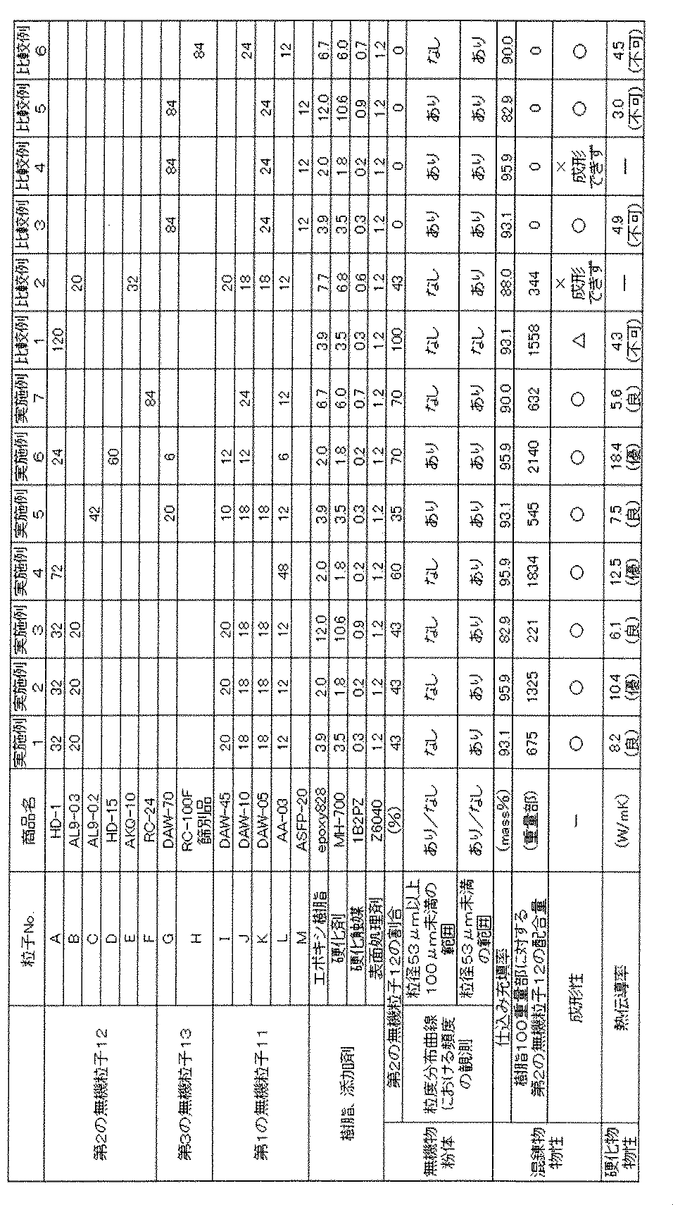
得られた無機粉体、および放熱性樹脂組成物について、以下の項目について測定または評価した。
(1)第2の無機粒子12の含有量
表2の配合で得られた無機粉体10gを取り分け、目開き100μmのメッシュを用いて、湿式篩法にて第2の無機粒子12を捕集した。
捕集した無機粒子の質量(g)を測定し、測定値を、最初に取り分けた無機粉体の質量10gで除することで、無機粉体中の第2の無機粒子12の含有量(質量%)を求めた。結果を表2に示す。
(2)粒度分布曲線
「(1)第2の無機粒子12の割合」において、第2の無機粒子12が除去された後の無機粉体10(粒径100μm未満の無機粉体10)について、粒度分布を測定し、粒度分布曲線を作成した。
粒径100μm未満の無機粉体10を、レーザー粒度分布測定装置〔日機装(株)製「マイクロトラック:MT-3300」〕を用いて、レーザー回折法により粒度分布を測定した。
得られた粒度分布曲線において、粒径53μm未満の範囲と、粒径53μm以上100μm未満の範囲との各々において、頻度が観測されるか否かを確認した、表2に示した。
(1)第2の無機粒子12の含有量
表2の配合で得られた無機粉体10gを取り分け、目開き100μmのメッシュを用いて、湿式篩法にて第2の無機粒子12を捕集した。
捕集した無機粒子の質量(g)を測定し、測定値を、最初に取り分けた無機粉体の質量10gで除することで、無機粉体中の第2の無機粒子12の含有量(質量%)を求めた。結果を表2に示す。
(2)粒度分布曲線
「(1)第2の無機粒子12の割合」において、第2の無機粒子12が除去された後の無機粉体10(粒径100μm未満の無機粉体10)について、粒度分布を測定し、粒度分布曲線を作成した。
粒径100μm未満の無機粉体10を、レーザー粒度分布測定装置〔日機装(株)製「マイクロトラック:MT-3300」〕を用いて、レーザー回折法により粒度分布を測定した。
得られた粒度分布曲線において、粒径53μm未満の範囲と、粒径53μm以上100μm未満の範囲との各々において、頻度が観測されるか否かを確認した、表2に示した。
(3)成形性
表2の配合で得られた混合物について、成形性の評価試験を行った。評価基準は以下の通りとした。表2の「成形性」の欄に、評価試験を示す。
「○」:問題なく成形できた。
「△」:成形はできたものの、成形体中に気泡を多く含んでいた。
「×」:無機粒子と樹脂との混合物の粘度が高くなり過ぎて成形できなかった、または、混合物が粉状で成形できなかった。
表2の配合で得られた混合物について、成形性の評価試験を行った。評価基準は以下の通りとした。表2の「成形性」の欄に、評価試験を示す。
「○」:問題なく成形できた。
「△」:成形はできたものの、成形体中に気泡を多く含んでいた。
「×」:無機粒子と樹脂との混合物の粘度が高くなり過ぎて成形できなかった、または、混合物が粉状で成形できなかった。
(4)熱伝導率
表2の配合で得られた混合物を、幅10mm×長さ10mm×厚さ1mmに成形し、その後に樹脂を固化させて、放熱性樹脂組成物(測定用の試料)を作成した。レーザーフラッシュ法による熱抵抗測定機(NETZSCH社製、LFA467)を用いて、試料の熱伝導率を測定した。熱伝導率が5W/mK未満を「不可」、5W/mK以上10W/mK未満を「良」、10W/mK以上を「優」とする。なお、比較例2および4は、混合物の成形性が悪く、測定用の試料を調製できなかったため、熱伝導率の測定を行わなかった。
表2の配合で得られた混合物を、幅10mm×長さ10mm×厚さ1mmに成形し、その後に樹脂を固化させて、放熱性樹脂組成物(測定用の試料)を作成した。レーザーフラッシュ法による熱抵抗測定機(NETZSCH社製、LFA467)を用いて、試料の熱伝導率を測定した。熱伝導率が5W/mK未満を「不可」、5W/mK以上10W/mK未満を「良」、10W/mK以上を「優」とする。なお、比較例2および4は、混合物の成形性が悪く、測定用の試料を調製できなかったため、熱伝導率の測定を行わなかった。
実施例1~7および比較例1~6について、以下に考察する。
実施例1~7は、使用した第2の無機粒子12(平均粒径200μm~15000の粒子A~DおよびF)のBET比表面積が2m2/g以下であった。また、篩別した第2の無機粒子12も、BET比表面積が2m2/g以下であった。
実施例1~7の無機粉体は、第2の無機粒子12を30~95質量%含んでいた。それらの無機粉体の粒度分布曲線を確認すると、粒径53μm未満の範囲に頻度が観測された。これにより、実施例1~7の無機粒子は、第1の無機粒子11を含むことが確認された。なお、実施例5および6では、さらに、粒度分布曲線の粒径53μm以上、100μm未満の範囲に頻度が観測された。これにより、実施例5および6の無機粒子は、第3の無機粒子13を含むことが確認された。
実施例1~7は、使用した第2の無機粒子12(平均粒径200μm~15000の粒子A~DおよびF)のBET比表面積が2m2/g以下であった。また、篩別した第2の無機粒子12も、BET比表面積が2m2/g以下であった。
実施例1~7の無機粉体は、第2の無機粒子12を30~95質量%含んでいた。それらの無機粉体の粒度分布曲線を確認すると、粒径53μm未満の範囲に頻度が観測された。これにより、実施例1~7の無機粒子は、第1の無機粒子11を含むことが確認された。なお、実施例5および6では、さらに、粒度分布曲線の粒径53μm以上、100μm未満の範囲に頻度が観測された。これにより、実施例5および6の無機粒子は、第3の無機粒子13を含むことが確認された。
実施例1~7の放熱性樹脂組成物(測定用の試料)では、樹脂100重量部に対する第2の無機粒子12の配合量は100重量部以上であり、得られた測定用試料の熱伝導率が5W/mK以上と良好であった。特に、実施例2、4および6では、樹脂100重量部に対する第2の無機粒子12の配合量は1000重量部以上であり、得られた測定用試料は、10W/mK以上と優れた熱伝導率を示した。
比較例1の無機粉体は、粒度分布曲線の粒径53μm未満の範囲に頻度が観測されなかった。つまり、比較例1の無機粉体は、第1の無機粒子11を含んでいない。そのため、放熱性樹脂組成物の保形性が悪く、成形体中に大きな気泡を含んでおり、放熱性樹脂組成物(測定用の試料)の熱伝導率が5W/mK未満となった。
比較例2の無機粉体は、使用した第2の無機粒子12(平均粒径2000μmの粒子E)のBET比表面積が2m2/g以上であった。また、篩別した第2の無機粒子12も、BET比表面積が2m2/g以上であった。そのため、第2の無機粒子12が樹脂原料を吸収して、混合物が粉状となった。その結果、混合物の成形性が著しく悪化して、放熱性樹脂組成物(測定用の試料)を調製することができなかった。
比較例3、5および6の無機粉体は、第2の無機粒子12を含んでいなかった。そのため、放熱性樹脂組成物(測定用の試料)の熱伝導率が5W/mK未満となった。
比較例4の無機粉体は、第2の無機粒子12を含んでいなかった。さらに、放熱性樹脂組成物(測定用の試料)を調製する際の仕込み充填率が高かったため、無機粉体と樹脂との混合物の粘度が高くなり過ぎた。そのため、混合物の成形性が著しく悪化して、放熱性樹脂組成物(測定用の試料)を調製することができなかった。
比較例4の無機粉体は、第2の無機粒子12を含んでいなかった。さらに、放熱性樹脂組成物(測定用の試料)を調製する際の仕込み充填率が高かったため、無機粉体と樹脂との混合物の粘度が高くなり過ぎた。そのため、混合物の成形性が著しく悪化して、放熱性樹脂組成物(測定用の試料)を調製することができなかった。
10 無機粉体
11 第1の無機粒子
12 第2の無機粒子
13 第3の無機粒子
20 放熱性樹脂組成物
200 混合物
30 樹脂
300 樹脂原料
90 型
151、152 孔
11 第1の無機粒子
12 第2の無機粒子
13 第3の無機粒子
20 放熱性樹脂組成物
200 混合物
30 樹脂
300 樹脂原料
90 型
151、152 孔
Claims (8)
- 放熱性樹脂組成物に使用される無機粉体であって、
粒径53μm未満の第1の無機粒子と、BET比表面積が2m2/g以下である、粒径100μm以上の第2の無機粒子とを含み、
前記第2の無機粒子の含有量が30~95質量%である、無機粉体。 - 断面SEM像において、前記第2の無機粒子の内部に存在する孔は、最大寸法40μm未満である、請求項1に記載の無機粉体。
- さらに、粒径53μm以上、100μm未満の第3の無機粒子を含む、請求項1または2に記載の無機粉体。
- 樹脂と、請求項1~3のいずれかに記載の無機粉体と、を含む放熱性樹脂組成物であって、
前記樹脂100重量部に対し、前記第2の無機粒子を100重量部以上含む、放熱性樹脂組成物。 - 放熱性樹脂組成物に使用される、無機粒子を含む無機粉体の製造方法であって、
粒径53μm未満の第1の無機粒子と、BET比表面積が2m2/g以下である、粒径100μm以上の第2の無機粒子とを、前記無機粉体が前記第2の無機粒子を30~95質量%含むように混合する工程を含む、無機粉体の製造方法。 - 前記第1の無機粒子および/または前記第2の無機粒子と、粒径53μm以上、100μm未満の第3の無機粒子を混合する工程をさらに含む、請求項5に記載の無機粉体の製造方法。
- 樹脂と、無機粒子む無機粉体とを含む放熱性樹脂組成物の製造方法であって、
粒径53μm未満の第1の無機粒子と、BET比表面積が2m2/g以下である、粒径100μm以上の第2の無機粒子と、樹脂原料とを、前記無機粉体が前記第2の無機粒子を30~95質量%含むように、かつ、前記樹脂原料100重量部に対し、前記第2の無機粒子が100重量部以上で配合されるように、混合する工程と、
得られた混合物を成形する工程と、を含む放熱性樹脂組成物の製造方法。 - 前記無機粉体は、粒径53μm以上、100μm未満の第3の無機粒子をさらに含む、請求項7に記載の放熱性樹脂組成物の製造方法。
Priority Applications (5)
| Application Number | Priority Date | Filing Date | Title |
|---|---|---|---|
| US17/418,240 US20220064400A1 (en) | 2018-12-27 | 2019-12-26 | Inorganic powder for heat-dissipating resin composition, heat-dissipating resin composition using same, and methods for producing same |
| KR1020217019910A KR20210106458A (ko) | 2018-12-27 | 2019-12-26 | 방열성 수지 조성물용 무기분체 및 이를 이용한 방열성 수지 조성물, 그리고 이들의 제조 방법 |
| EP19902646.9A EP3904310A4 (en) | 2018-12-27 | 2019-12-26 | INORGANIC POWDER FOR HEAT-DISSIPTING RESIN COMPOSITION, HEAT-DISSIPTING RESIN COMPOSITION THEREOF AND METHOD FOR THE PREPARATION THEREOF |
| CN201980086309.8A CN113227238B (zh) | 2018-12-27 | 2019-12-26 | 散热性树脂组合物用无机粉体、使用了该散热性树脂组合物用无机粉体的散热性树脂组合物以及它们的制造方法 |
| JP2020562433A JP7470051B2 (ja) | 2018-12-27 | 2019-12-26 | 放熱性樹脂組成物用無機粉体およびそれを用いた放熱性樹脂組成物、並びにそれらの製造方法 |
Applications Claiming Priority (2)
| Application Number | Priority Date | Filing Date | Title |
|---|---|---|---|
| JP2018-244647 | 2018-12-27 | ||
| JP2018244647 | 2018-12-27 |
Publications (1)
| Publication Number | Publication Date |
|---|---|
| WO2020138335A1 true WO2020138335A1 (ja) | 2020-07-02 |
Family
ID=71126003
Family Applications (1)
| Application Number | Title | Priority Date | Filing Date |
|---|---|---|---|
| PCT/JP2019/051239 Ceased WO2020138335A1 (ja) | 2018-12-27 | 2019-12-26 | 放熱性樹脂組成物用無機粉体およびそれを用いた放熱性樹脂組成物、並びにそれらの製造方法 |
Country Status (7)
| Country | Link |
|---|---|
| US (1) | US20220064400A1 (ja) |
| EP (1) | EP3904310A4 (ja) |
| JP (1) | JP7470051B2 (ja) |
| KR (1) | KR20210106458A (ja) |
| CN (1) | CN113227238B (ja) |
| TW (1) | TWI840482B (ja) |
| WO (1) | WO2020138335A1 (ja) |
Cited By (4)
| Publication number | Priority date | Publication date | Assignee | Title |
|---|---|---|---|---|
| WO2023013441A1 (ja) * | 2021-08-05 | 2023-02-09 | 株式会社トクヤマ | 組成物およびフィラー混合物 |
| WO2023210492A1 (ja) * | 2022-04-28 | 2023-11-02 | 住友化学株式会社 | 樹脂組成物およびそれに用いるアルミナ粉末 |
| WO2023210493A1 (ja) * | 2022-04-28 | 2023-11-02 | 住友化学株式会社 | 樹脂組成物およびそれに用いるアルミナ粉末 |
| CN117136170A (zh) * | 2021-03-31 | 2023-11-28 | 日铁化学材料株式会社 | 球状氧化铝颗粒混合物及其制造方法、以及包含该球状氧化铝颗粒混合物的树脂复合组合物及树脂复合体 |
Families Citing this family (2)
| Publication number | Priority date | Publication date | Assignee | Title |
|---|---|---|---|---|
| WO2023007894A1 (ja) * | 2021-07-29 | 2023-02-02 | 昭和電工株式会社 | 熱伝導性樹脂組成物、硬化物、熱伝導部材及び電子機器 |
| GB2633405A (en) * | 2023-09-11 | 2025-03-12 | Landa Labs 2012 Ltd | Method an apparatus for 3D printing |
Citations (7)
| Publication number | Priority date | Publication date | Assignee | Title |
|---|---|---|---|---|
| JPH0888488A (ja) * | 1994-09-20 | 1996-04-02 | Tokai Rubber Ind Ltd | 放熱シートおよびその製法 |
| JP2000232190A (ja) | 1999-02-12 | 2000-08-22 | Fuji Kobunshi Kogyo Kk | 熱伝導性エラストマー組成物およびこれを用いた熱伝導性エラストマー |
| JP2008270678A (ja) * | 2007-04-25 | 2008-11-06 | Mitsubishi Electric Corp | 絶縁シートおよび半導体装置 |
| JP2011088759A (ja) * | 2009-10-20 | 2011-05-06 | Nikkato:Kk | アルミナ質耐火物及びその製造方法 |
| JP2016017014A (ja) * | 2014-07-09 | 2016-02-01 | 株式会社ジーエル・マテリアルズホールディングス | 高熱伝導性・電気絶縁性・低熱膨張性粉末及びそれを用いた放熱構造体、並びにその粉末の製造方法 |
| WO2018139642A1 (ja) * | 2017-01-30 | 2018-08-02 | 積水化学工業株式会社 | 樹脂材料及び積層体 |
| WO2019065148A1 (ja) * | 2017-09-28 | 2019-04-04 | 富士フイルム株式会社 | 放熱シートおよび放熱シート付きデバイス |
Family Cites Families (4)
| Publication number | Priority date | Publication date | Assignee | Title |
|---|---|---|---|---|
| WO2009136508A1 (ja) * | 2008-05-08 | 2009-11-12 | 富士高分子工業株式会社 | 熱伝導性樹脂組成物 |
| JP6179015B2 (ja) * | 2016-07-06 | 2017-08-16 | 株式会社アドマテックス | 粉粒体及びその製造方法、並びに特性改質材 |
| JP6607166B2 (ja) * | 2016-10-31 | 2019-11-20 | 信越化学工業株式会社 | 熱伝導性シリコーン組成物及び半導体装置 |
| JP6659639B2 (ja) * | 2017-03-22 | 2020-03-04 | 株式会社東芝 | 複合電解質、二次電池、電池パック及び車両 |
-
2019
- 2019-12-26 TW TW108147730A patent/TWI840482B/zh not_active IP Right Cessation
- 2019-12-26 WO PCT/JP2019/051239 patent/WO2020138335A1/ja not_active Ceased
- 2019-12-26 EP EP19902646.9A patent/EP3904310A4/en not_active Withdrawn
- 2019-12-26 CN CN201980086309.8A patent/CN113227238B/zh not_active Expired - Fee Related
- 2019-12-26 US US17/418,240 patent/US20220064400A1/en not_active Abandoned
- 2019-12-26 KR KR1020217019910A patent/KR20210106458A/ko active Pending
- 2019-12-26 JP JP2020562433A patent/JP7470051B2/ja active Active
Patent Citations (7)
| Publication number | Priority date | Publication date | Assignee | Title |
|---|---|---|---|---|
| JPH0888488A (ja) * | 1994-09-20 | 1996-04-02 | Tokai Rubber Ind Ltd | 放熱シートおよびその製法 |
| JP2000232190A (ja) | 1999-02-12 | 2000-08-22 | Fuji Kobunshi Kogyo Kk | 熱伝導性エラストマー組成物およびこれを用いた熱伝導性エラストマー |
| JP2008270678A (ja) * | 2007-04-25 | 2008-11-06 | Mitsubishi Electric Corp | 絶縁シートおよび半導体装置 |
| JP2011088759A (ja) * | 2009-10-20 | 2011-05-06 | Nikkato:Kk | アルミナ質耐火物及びその製造方法 |
| JP2016017014A (ja) * | 2014-07-09 | 2016-02-01 | 株式会社ジーエル・マテリアルズホールディングス | 高熱伝導性・電気絶縁性・低熱膨張性粉末及びそれを用いた放熱構造体、並びにその粉末の製造方法 |
| WO2018139642A1 (ja) * | 2017-01-30 | 2018-08-02 | 積水化学工業株式会社 | 樹脂材料及び積層体 |
| WO2019065148A1 (ja) * | 2017-09-28 | 2019-04-04 | 富士フイルム株式会社 | 放熱シートおよび放熱シート付きデバイス |
Non-Patent Citations (1)
| Title |
|---|
| See also references of EP3904310A4 |
Cited By (4)
| Publication number | Priority date | Publication date | Assignee | Title |
|---|---|---|---|---|
| CN117136170A (zh) * | 2021-03-31 | 2023-11-28 | 日铁化学材料株式会社 | 球状氧化铝颗粒混合物及其制造方法、以及包含该球状氧化铝颗粒混合物的树脂复合组合物及树脂复合体 |
| WO2023013441A1 (ja) * | 2021-08-05 | 2023-02-09 | 株式会社トクヤマ | 組成物およびフィラー混合物 |
| WO2023210492A1 (ja) * | 2022-04-28 | 2023-11-02 | 住友化学株式会社 | 樹脂組成物およびそれに用いるアルミナ粉末 |
| WO2023210493A1 (ja) * | 2022-04-28 | 2023-11-02 | 住友化学株式会社 | 樹脂組成物およびそれに用いるアルミナ粉末 |
Also Published As
| Publication number | Publication date |
|---|---|
| US20220064400A1 (en) | 2022-03-03 |
| EP3904310A4 (en) | 2022-09-07 |
| KR20210106458A (ko) | 2021-08-30 |
| TWI840482B (zh) | 2024-05-01 |
| CN113227238A (zh) | 2021-08-06 |
| JP7470051B2 (ja) | 2024-04-17 |
| CN113227238B (zh) | 2023-04-11 |
| JPWO2020138335A1 (ja) | 2021-11-11 |
| TW202033643A (zh) | 2020-09-16 |
| EP3904310A1 (en) | 2021-11-03 |
Similar Documents
| Publication | Publication Date | Title |
|---|---|---|
| WO2020138335A1 (ja) | 放熱性樹脂組成物用無機粉体およびそれを用いた放熱性樹脂組成物、並びにそれらの製造方法 | |
| JP7325670B2 (ja) | 球状アルミナ粒子混合物及びその製造方法、並びに当該球状アルミナ粒子混合物を含む樹脂複合組成物及び樹脂複合体 | |
| JP7096921B2 (ja) | 六方晶窒化ホウ素粉末及びその製造方法、並びにそれを用いた組成物及び放熱材 | |
| JP7069485B2 (ja) | 六方晶窒化ホウ素粉末及びその製造方法、並びにそれを用いた組成物及び放熱材 | |
| CN109153811B (zh) | 铝产品及其在具有高热导率的聚合物组合物中的用途 | |
| CN115348952B (zh) | 氧化铝粉末、树脂组合物以及散热部件 | |
| JP6092806B2 (ja) | 酸化亜鉛粉体、放熱性フィラー、樹脂組成物、放熱性グリース及び放熱性塗料組成物 | |
| JP2026016795A (ja) | 窒化ホウ素凝集粉末、放熱シート及び半導体デバイス | |
| JP5354724B2 (ja) | セラミックス粉末及びその用途 | |
| TW202043142A (zh) | 氮化硼粉末及其製造方法、及複合體以及散熱構件 | |
| CN116235296A (zh) | 氧化镁粉末、填料组合物、树脂组合物和散热部件 | |
| CN116134611A (zh) | 氧化镁粉末、填料组合物、树脂组合物和散热部件 | |
| JP2014189701A (ja) | 高熱伝導性樹脂硬化物、高熱伝導性半硬化樹脂フィルム及び高熱伝導性樹脂組成物 | |
| JP6786047B2 (ja) | 熱伝導シートの製造方法 | |
| CN116601763A (zh) | 氧化镁粉末、填料组合物、树脂组合物以及散热部件 | |
| WO2024143105A1 (ja) | アルミナ粉末および樹脂組成物 | |
| WO2024135832A1 (ja) | 球状アルミナ粒子及びその製造方法 | |
| JP6745521B2 (ja) | 酸化マグネシウム粒子及びその製造方法、並びに放熱材料 | |
| JP2020053531A (ja) | 熱伝導性シート前駆体、並びに該前駆体から得られる熱伝導性シート及びその製造方法 | |
| JP2010138267A (ja) | 熱伝導性樹脂組成物 | |
| JP2019121708A (ja) | 熱伝導性シート前駆体、並びに該前駆体から得られる熱伝導性シート及びその製造方法 | |
| KR102049600B1 (ko) | 세라믹 나노융복합 방열필름 제조방법 | |
| US11910571B2 (en) | Housing parts, housings and processes for preparing the same | |
| TW202547791A (zh) | 球狀氧化鋁粒子混合物及包含其之樹脂複合組成物 | |
| KR20230079848A (ko) | 반도체 밀봉용 조성물 및 이를 통해 성형된 반도체 부품 |
Legal Events
| Date | Code | Title | Description |
|---|---|---|---|
| 121 | Ep: the epo has been informed by wipo that ep was designated in this application |
Ref document number: 19902646 Country of ref document: EP Kind code of ref document: A1 |
|
| ENP | Entry into the national phase |
Ref document number: 2020562433 Country of ref document: JP Kind code of ref document: A |
|
| NENP | Non-entry into the national phase |
Ref country code: DE |
|
| ENP | Entry into the national phase |
Ref document number: 2019902646 Country of ref document: EP Effective date: 20210727 |