WO2020144832A1 - ユーザ端末及び無線通信方法 - Google Patents
ユーザ端末及び無線通信方法 Download PDFInfo
- Publication number
- WO2020144832A1 WO2020144832A1 PCT/JP2019/000605 JP2019000605W WO2020144832A1 WO 2020144832 A1 WO2020144832 A1 WO 2020144832A1 JP 2019000605 W JP2019000605 W JP 2019000605W WO 2020144832 A1 WO2020144832 A1 WO 2020144832A1
- Authority
- WO
- WIPO (PCT)
- Prior art keywords
- harq
- ack
- slot
- pdsch
- candidate
- Prior art date
- Legal status (The legal status is an assumption and is not a legal conclusion. Google has not performed a legal analysis and makes no representation as to the accuracy of the status listed.)
- Ceased
Links
Images










Classifications
-
- H—ELECTRICITY
- H04—ELECTRIC COMMUNICATION TECHNIQUE
- H04L—TRANSMISSION OF DIGITAL INFORMATION, e.g. TELEGRAPHIC COMMUNICATION
- H04L1/00—Arrangements for detecting or preventing errors in the information received
- H04L1/12—Arrangements for detecting or preventing errors in the information received by using return channel
- H04L1/16—Arrangements for detecting or preventing errors in the information received by using return channel in which the return channel carries supervisory signals, e.g. repetition request signals
- H04L1/18—Automatic repetition systems, e.g. Van Duuren systems
- H04L1/1867—Arrangements specially adapted for the transmitter end
- H04L1/1896—ARQ related signaling
-
- H—ELECTRICITY
- H04—ELECTRIC COMMUNICATION TECHNIQUE
- H04L—TRANSMISSION OF DIGITAL INFORMATION, e.g. TELEGRAPHIC COMMUNICATION
- H04L1/00—Arrangements for detecting or preventing errors in the information received
- H04L1/12—Arrangements for detecting or preventing errors in the information received by using return channel
- H04L1/16—Arrangements for detecting or preventing errors in the information received by using return channel in which the return channel carries supervisory signals, e.g. repetition request signals
- H04L1/18—Automatic repetition systems, e.g. Van Duuren systems
- H04L1/1867—Arrangements specially adapted for the transmitter end
- H04L1/1887—Scheduling and prioritising arrangements
-
- H—ELECTRICITY
- H04—ELECTRIC COMMUNICATION TECHNIQUE
- H04L—TRANSMISSION OF DIGITAL INFORMATION, e.g. TELEGRAPHIC COMMUNICATION
- H04L1/00—Arrangements for detecting or preventing errors in the information received
- H04L1/12—Arrangements for detecting or preventing errors in the information received by using return channel
- H04L1/16—Arrangements for detecting or preventing errors in the information received by using return channel in which the return channel carries supervisory signals, e.g. repetition request signals
- H04L1/1607—Details of the supervisory signal
- H04L1/1664—Details of the supervisory signal the supervisory signal being transmitted together with payload signals; piggybacking
-
- H—ELECTRICITY
- H04—ELECTRIC COMMUNICATION TECHNIQUE
- H04L—TRANSMISSION OF DIGITAL INFORMATION, e.g. TELEGRAPHIC COMMUNICATION
- H04L1/00—Arrangements for detecting or preventing errors in the information received
- H04L1/12—Arrangements for detecting or preventing errors in the information received by using return channel
- H04L1/16—Arrangements for detecting or preventing errors in the information received by using return channel in which the return channel carries supervisory signals, e.g. repetition request signals
- H04L1/18—Automatic repetition systems, e.g. Van Duuren systems
- H04L1/1812—Hybrid protocols; Hybrid automatic repeat request [HARQ]
-
- H—ELECTRICITY
- H04—ELECTRIC COMMUNICATION TECHNIQUE
- H04L—TRANSMISSION OF DIGITAL INFORMATION, e.g. TELEGRAPHIC COMMUNICATION
- H04L1/00—Arrangements for detecting or preventing errors in the information received
- H04L1/12—Arrangements for detecting or preventing errors in the information received by using return channel
- H04L1/16—Arrangements for detecting or preventing errors in the information received by using return channel in which the return channel carries supervisory signals, e.g. repetition request signals
- H04L1/18—Automatic repetition systems, e.g. Van Duuren systems
- H04L1/1829—Arrangements specially adapted for the receiver end
Definitions
- the present disclosure relates to a user terminal and a wireless communication method in a next-generation mobile communication system.
- LTE Long Term Evolution
- 3GPP Rel. 10-14 LTE-Advanced (3GPP Rel. 10-14) has been specified for the purpose of further increasing the capacity and sophistication of LTE (Third Generation Partnership Project (3GPP) Release (Rel.) 8, 9).
- a successor system to LTE for example, 5th generation mobile communication system (5G), 5G+(plus), New Radio (NR), 3GPP Rel.15 or later) is also under consideration.
- 5G 5th generation mobile communication system
- 5G+(plus) 5th generation mobile communication system
- NR New Radio
- 3GPP Rel.15 or later 3th generation mobile communication system
- the user terminal (User Equipment (UE)) has a UL data channel (for example, Physical Uplink Shared Channel (PUSCH)) and a UL control channel (for example, Physical Uplink).
- PUSCH Physical Uplink Shared Channel
- UL control channel for example, Physical Uplink
- Send uplink control information (Uplink Control Information (UCI)) using at least one of Control Channel (PUCCH).
- UCI Uplink Control Information
- E-UTRA Evolved Universal Terrestrial Radio Access
- E-UTRAN Evolved Universal Terrestrial Radio Access Network
- NR future wireless communication systems
- delivery confirmation information Hybrid Automatic Repeat reQuest-ACKnowledgement (HARQ-ACK), ACKnowledgement/Non-ACKnowledgement (ACK/NACK), or DL signal (for example, PDSCH), or
- a value indicating a transmission timing also referred to as A/N, etc.
- DCI Downlink Control Information
- the UE determines a codebook (also referred to as a HARQ-ACK codebook, a HARQ codebook, etc.) that includes a predetermined HARQ-ACK bit based on the HARQ-ACK timing value, and determines the codebook. Feedback to the base station is being considered. Therefore, it is desired that the UE can appropriately control at least one of determination and feedback of the codebook.
- a codebook also referred to as a HARQ-ACK codebook, a HARQ codebook, etc.
- an object of the present disclosure is to provide a user terminal and a wireless communication method capable of appropriately controlling at least one of determination and feedback of a HARQ-ACK codebook.
- the user terminal is used in the time unit based on the Hybrid Automatic Repeat reQuest-ACKnowledge (HARQ-ACK) timing value using the time unit shorter than the slot and the time unit format.
- a control unit for determining a set of one or more candidate opportunities for reception of possible downlink shared channels; and a transmission unit for transmitting a codebook determined based on the set of candidate opportunities. To do.
- At least one of HARQ-ACK codebook determination and feedback can be appropriately controlled.
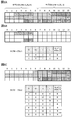
- FIG. 1A to 1C are diagrams showing examples of slot-level HARQ-ACK timing values.
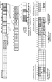
- FIG. 2 is a diagram illustrating a first example of a slot level quasi-static codebook determination operation.
- FIG. 3 is a diagram illustrating a second example of the slot-level quasi-static codebook determination operation.
- FIG. 4 is a diagram showing a third example of the quasi-static codebook determination operation at the slot level.
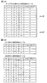
- 5A and 5B are diagrams showing an example of sub-slot level HARQ-ACK timing values according to the first example.
- 6A to 6C are diagrams showing an example of a sub-table of the PDSCH time domain RA table according to the first example.
- FIG. 1A to 1C are diagrams showing examples of slot-level HARQ-ACK timing values.
- FIG. 2 is a diagram illustrating a first example of a slot level quasi-static codebook determination operation.
- FIG. 3 is a diagram illustrating a second example of the slot-level quasi-static codebook
- FIG. 7 is a diagram illustrating a first example of a sub-slot level quasi-static codebook determination operation according to the first aspect.
- FIG. 8 is a diagram illustrating a second example of the sub-slot level quasi-static codebook determination operation according to the first aspect.
- FIG. 9 is a diagram illustrating a third example of the sub-slot level quasi-static codebook determination operation according to the first aspect.
- FIG. 10 is a diagram showing an example of slots according to the precondition of the second aspect.
- FIG. 11 is a diagram showing an example of a slot level quasi-static HARQ-ACK codebook determination operation according to the first method of the second aspect.
- FIG. 12 is a diagram showing an example of a sub-slot level quasi-static HARQ-ACK codebook determination operation according to the first method of the second aspect.
- 13A and 13B are diagrams illustrating an example of the PDSCH time domain RA for each service according to the second method of the second aspect.
- FIG. 14 is a diagram showing an example of a set of candidate PDSCH reception opportunities for each service, which is determined based on the HARQ-ACK timing value K 1 at the slot level according to the second method of the second aspect.
- FIG. 15 is a diagram showing an example of a slot level quasi-static HARQ-ACK codebook determination operation according to the second method of the second aspect.
- FIG. 16 is a diagram showing an example of a set of candidate PDSCH reception opportunities for each service determined based on the sub-slot level HARQ-ACK timing value K 1 .
- FIG. 17 is a diagram showing an example of a sub-slot level quasi-static HARQ-ACK codebook determination operation according to the second method of the second aspect.
- FIG. 18 is a diagram showing an example of a set of candidate PDSCH reception opportunities for each service according to the third method of the second aspect.
- FIG. 19 is a diagram showing an example of a quasi-static HARQ-ACK codebook determination operation for eMBB according to the third method of the second aspect.
- FIG. 20 is a diagram showing an example of a quasi-static HARQ-ACK codebook determining operation for URLLC according to the third method of the second aspect.
- FIG. 21 is a diagram showing an example of a common HARQ-ACK codebook according to option 1 of the second aspect.
- FIG. 22 is a diagram showing another example of the common HARQ-ACK codebook according to the option 1 of the second aspect.
- FIG. 23 is a diagram showing an example of a schematic configuration of a wireless communication system according to an embodiment.
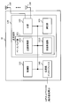
- FIG. 24 is a diagram illustrating an example of the configuration of the base station according to the embodiment.
- FIG. 25 is a diagram illustrating an example of the configuration of the user terminal according to the embodiment.
- FIG. 26 is a diagram illustrating an example of a hardware configuration of the base station and the user terminal according to the embodiment.
- a user terminal In NR, a user terminal (UE: User Equipment) sends delivery confirmation information (Hybrid Automatic Repeat reACK-ACKnowledge (HARQ-ACK), ACKnowledge/Non-ACK) to a downlink shared channel (also called Physical Downlink Shared Channel (PDSCH)).
- Delivery confirmation information Hybrid Automatic Repeat reACK-ACKnowledge (HARQ-ACK), ACKnowledge/Non-ACK
- HARQ-ACK Hybrid Automatic Repeat reACK-ACKnowledge
- ACKnowledge/Non-ACK ACKnowledge/Non-ACK
- PDSCH Physical Downlink Shared Channel
- the value of a predetermined field in DCI (for example, DCI format 1_0 or 1_1) used for PDSCH scheduling indicates the feedback timing of HARQ-ACK for the PDSCH.
- the value of the predetermined field may be mapped to the value of k.
- the predetermined field is called, for example, a PDSCH-HARQ feedback timing indication (PDSCH-to-HARQ_feedback timing indicator) field.
- the NR also determines the PUCCH resource used for HARQ-ACK feedback for the PDSCH, based on the value of a predetermined field in the DCI used for PDSCH scheduling (eg, DCI format 1_0 or 1_1).
- the predetermined field may be called, for example, a PUCCH resource indication (PUCCH resource indicator (PRI)) field, an ACK/NACK resource indication (ACK/NACK resource indicator (ARI)) field, or the like.
- PRI PUCCH resource indicator
- ARI ACK/NACK resource indicator
- the PUCCH resource mapped to each value of the predetermined field may be configured (configured) in the UE in advance by an upper layer parameter (for example, ResourceList in PUCCH-ResourceSet). Moreover, the said PUCCH resource may be set to UE for every set (PUCCH resource set) containing one or more PUCCH resources.
- an upper layer parameter for example, ResourceList in PUCCH-ResourceSet.
- NR also considers that the UE can transmit one or more uplink control channels (Physical Uplink Control Channel (PUCCH)) for HARQ-ACK in a single slot.
- PUCCH Physical Uplink Control Channel
- one or more HARQ-ACKs are mapped to a HARQ-ACK codebook, and the HARQ-ACK codebook is a PUCCH resource designated by a predetermined DCI (eg, the latest (last) DCI). It may be transmitted.
- a predetermined DCI eg, the latest (last) DCI
- the HARQ-ACK codebook includes a time domain (for example, a slot), a frequency domain (for example, a component carrier (Component Carrier (CC))), a spatial domain (for example, a layer), and a transport block (Transport Block (TB). )), and at least one unit of a group of code blocks (code block group (Code Block Group (CBG)) that configures TB, may be configured to include bits for HARQ-ACK.
- the CC is also called a cell, a serving cell, a carrier, or the like.
- the bit is also called a HARQ-ACK bit, HARQ-ACK information, HARQ-ACK information bit, or the like.
- HARQ-ACK codebook is also called PDSCH-HARQ-ACK codebook (pdsch-HARQ-ACK-Codebook), codebook, HARQ codebook, HARQ-ACK size, and so on.
- the number of bits (size) included in the HARQ-ACK codebook may be determined semi-statically or dynamically.
- the HARQ-ACK codebook whose size is quasi-statically determined is also called a quasi-static HARQ-ACK codebook, a type-1 HARQ-ACK codebook, a quasi-static codebook, or the like.
- the HARQ-ACK codebook whose size is dynamically determined is also called a dynamic HARQ-ACK codebook, a type-2 HARQ-ACK codebook, a dynamic codebook, or the like.
- Whether to use the quasi-static HARQ-ACK codebook or the dynamic HARQ-ACK codebook may be set in the UE by an upper layer parameter (eg, pdsch-HARQ-ACK-Codebook).
- an upper layer parameter eg, pdsch-HARQ-ACK-Codebook
- the UE may feed back the HARQ-ACK bit corresponding to the predetermined range regardless of the presence or absence of PDSCH scheduling in the predetermined range.
- the predetermined range is also called a HARQ-ACK window, a HARQ-ACK bundling window, a HARQ-ACK feedback window, a bundling window, a feedback window, or the like.
- the slot-level quasi-static HARQ-ACK codebook may be determined based on at least one parameter of a) to d) below: a) a value indicating HARQ-ACK timing (HARQ-ACK timing value) K 1 , b) A table (PDSCH time domain resource allocation table) used for determining time domain resources allocated to the PDSCH (PDSCH time domain resource allocation table), c) When different subcarrier intervals are set for the downlink and the uplink, the ratio 2 between the configuration of the downlink (or downlink BWP) subcarrier interval ⁇ DL and the configuration of the uplink (or upstream BWP) subcarrier interval ⁇ UL 2 Raised to the power of ( ⁇ DL ⁇ UL ), d) Cell-specific TDD UL/DL configuration (eg, TDD-UL-DL-ConfigurationCommon) and slot-specific configuration that overwrites cell-specific TDD UL/DL configuration (eg, TDD-UL-DL
- the UE transmits the HARQ-ACK bit in the PUCCH transmitted in the slot n in the serving cell c (or the active downlink BWP and uplink BWP of the serving cell c) based on the at least one parameter.
- the set of possible candidate PDSCH reception opportunities M A,c may be determined.
- the UE may determine the set of reception opportunities M A,c of the candidate PDSCH according to the following steps 1) 2).
- Step 1) The UE determines the HARQ-ACK window based on the slot-level HARQ-ACK timing value K 1 .
- the HARQ-ACK window can be said to be the cardinality of the set C(K 1 ) of the HARQ-ACK timing value K 1 .
- C(K 1 ) ⁇ 7,6,5 ⁇ .
- C(K 1 ) including one or more HARQ-ACK timing values K 1 is determined based on at least one of a predetermined field value in DCI and an upper layer parameter (eg, dl-DataToUL-ACK). Good.
- Step 2) The UE may determine the reception opportunity M A,c of the candidate PDSCH in each slot for each HARQ-ACK timing value K 1 in C(K 1 ).
- the UE repeats the following steps 2-1) and 2-2) for each HARQ-ACK timing value K 1 in C(K 1 ) to determine a quasi-static HARQ-ACK codebook to be transmitted in slot #n. You may.
- Step 2-1) The UE receives the candidate PDSCH available in slot #n-K 1 based on at least one of the PDSCH time domain RA table and the format of slot #n-K 1 corresponding to HARQ-ACK timing value K 1.
- the opportunity M A,c may be determined.
- the candidate PDSCH reception opportunity may be a period (also referred to as an opportunity or a candidate opportunity) that is one or more candidates for PDSCH reception.
- the UE determines the candidate PDSCH reception opportunity M A,c for slot #n-K 1 based on the PDSCH time domain RA table, and then determines the candidate based on the format of slot #n-K 1. At least a part of the PDSCH reception opportunities M A,c may be excluded as unavailable (or at least a part of the candidate PDSCH reception opportunities M A,c may be used based on the format of the slot #n ⁇ K 1 ). May be extracted if possible).
- the format of the slot #n-K 1 is a cell-specific TDD UL/DL configuration (for example, TDD-UL-DL-ConfigurationCommon) or a slot-specific TDD UL/DL configuration (for example, TDD-UL-DL- It may be determined based on at least one of ConfigDedicated) and DCI.
- Step 2-2) The UE gives an index to the reception opportunity M A,c of the candidate PDSCH determined in step 2-1).
- the UE assigns the same index (value) to a plurality of candidate PDSCH reception opportunities M A,c in which at least some of the symbols overlap, and the HARQ-ACK bit is assigned to each candidate PDSCH reception opportunity index (value). May be generated.
- FIG. 1B an example of the PDSCH time domain RA table is shown.
- the row index (row index (RI)) is offset K 0 , the index S of the start symbol to which the PDSCH is assigned, and the number of symbols assigned to the PDSCH ( It may be associated with at least one of the allocation length) L and the mapping type of PDSCH.
- Each row of the PDSCH time domain RA table may indicate a PDSCH time domain RA for the PDSCH (ie, a candidate PDSCH reception opportunity).
- FIG. 1C shows an example of the candidate PDSCH reception opportunities M A,c determined based on the PDSCH time domain RA table of FIG. 1B.
- FIG. 2 shows a case in which all the slots #n-K 1 have a format configured with downlink symbols (D).
- An identifier or ID is given.
- the same index may be given to the plurality of candidate PDSCH reception opportunities M A,c in which at least some symbols overlap (collide).
- the candidate PDSCH reception opportunity M A,c in slot #n-K 1 includes the candidate PDSCH reception opportunities identified by different indexes (values) “0” to “4”.
- the UE may generate a predetermined number (eg, 1 bit) of HARQ-ACK bits for the candidate PDSCH reception opportunity of each index.
- one UE has five candidate PDSCH reception opportunities M A,c available in slot #n-K 1 and therefore a semi-static HARQ-ACK including 5 HARQ-ACK bits.
- a codebook may be generated.
- FIG. 3 shows a case where slot #n-K 1 has a format including a downlink symbol (D), an uplink symbol (U), and a guard period (G).
- symbols #0 to #9 in slot #n ⁇ K 1 eg, slot #n-5 in FIG. 1A
- symbols #12 and #13 are uplink symbols
- symbols #12 and #13 are symbols.
- #10 and #11 are the guard period.
- the PDSCH reception opportunity M A,c is extracted , and an index (identifier or ID) is given to the extracted candidate PDSCH reception opportunity M A,c .
- a predetermined number eg, 9 bits
- 9 bits of HARQ-ACK bits corresponding to the candidate PDSCH reception opportunities identified by “” to “8” may be included.
- FIG. 4 shows a case where the slots #n-K 1 are all in a format including uplink symbols (U). For example, in FIG. 4, all symbols #0 to #13 in slot #n ⁇ K 1 (for example, slot #n-5 in FIG. 1A) are uplink symbols.
- the candidate PDSCH reception opportunities available in slot #n-K 1 may not be extracted.
- the quasi-static HARQ-ACK codebook based on the slot-level HARQ-ACK timing value K 1 .
- the requirements for ultra-reliable and low-delay services for example, related services (URLLC services) related to Ultra Reliable and Low Latency Communications (URLLC)
- URLLC services related services
- Supporting (introducing) the HARQ-ACK timing value K 1 using a time unit is also under consideration.
- the same UE supports multiple services with different requirements (eg, URLLC service and high-speed and large-capacity service (eg, service related to enhanced Mobile Broad Band (eMBB) (eMBB service))). It is also possible to do.
- URLLC service e.g. URLLC service and high-speed and large-capacity service (eg, service related to enhanced Mobile Broad Band (eMBB) (eMBB service))). It is also possible to do.
- eMBB service enhanced Mobile Broad Band
- the present inventors have studied a method (second aspect) in which a UE supporting a plurality of services appropriately controls at least one of determination and feedback of a quasi-static HARQ-ACK codebook, and the present invention Came to.
- Transport Block also referred to as a code word (CW)
- TB Transport Block
- CW code word
- a single HARQ-ACK bit is generated for a single TB, but in the present embodiment, for a single code block group (Code Block Group (CBG)). It is also applicable as appropriate when a single HARQ-ACK bit is generated.
- 1 TB is segmented into one or more code blocks (Code Block (CB)). 1TB includes one or more CBGs, and one CBG may include one or more CBs.
- the UE supports a specific service (for example, URLLC service) and does not perform another service (for example, eMBB service), but the present invention is not limited to this.
- a service e.g., eMBB service
- a specific service e.g., URLLC service
- a plurality of different services are commonly used. It is also applicable to the case of accommodating with the wireless interface of.
- the UE supports a HARQ-ACK timing value K 1 with a time unit shorter than a slot (consisting of fewer symbols than slots).
- the time unit is called a half slot, a sub slot, a mini slot, or the like, and may be composed of a predetermined number of symbols (for example, 2, 3, 4 or 7 symbols).
- each half slot is composed of 7 symbols, and one slot may include two half slots.
- the half slot may be paraphrased as a 7-slot subslot.
- the sub-slot may be composed of 3 or 4 symbols, and one sub-slot may include 4 sub-slots.
- the sub-slot may be composed of 2 symbols, and 7 sub-slots may be included in one slot.
- the half slot may be referred to as a 7-symbol sub slot.
- the granularity of HARQ-ACK timing value K 1 (eg, slot, half slot (7-symbol subslot), 3/4 symbol subslot, or 2 symbol subslot in FIG. 5A) is higher
- the UE may be notified using at least one of the layer parameter and the DCI.
- the UE may determine the granularity of the HARQ-ACK timing value K 1 based on (1) SIB or (2) UE-specific RRC parameter (dedicated RRC).
- the granularity of the HARQ-ACK timing value K 1 may be configured (configured) by a predetermined parameter in the SIB.
- a UE that does not support the granularity of the HARQ-ACK timing value K 1 shorter than the slot that is, a UE that supports only the HARQ-ACK timing value K 1 at the slot level
- resources (PRACH resources) for a random access channel may be classified based on the granularity of the HARQ-ACK timing value K 1 .
- a UE that supports only the HARQ-ACK timing value K 1 at the slot level and a UE that supports the HARQ-ACK timing value K 1 at a time unit shorter than the slot respectively use different PRACH resource pools. May be.
- the base station is configured so that the UE is more likely than the slot before the HARQ-ACK (first HARQ-ACK) transmission for the contention resolution message (message 4) in the random access procedure.
- the HARQ-ACK timing value K 1 of a short time unit for example, the half slot or the sub slot
- the granularity of HARQ-ACK timing value K 1 may be configured by UE-specific RRC parameters.
- the UE may transmit information (capability information) indicating that the HARQ-ACK timing value K 1 shorter than the slot is supported to the base station.
- the UE receives information indicating the granularity of the HARQ-ACK timing value K 1 (for example, either half slot, 3/4 symbol subslot, or 2 symbol subslot) from the base station.
- a HARQ-ACK timing value K 1 shorter than the slot may be set.
- FIG. 5B an example of granularity of HARQ-ACK timing value K 1 shorter than a slot is shown.
- the granularity is a sub-slot (half slot) of 7 symbols, but it is not limited to this.
- the granularity may be a 3/4 symbol subslot, a 2 symbol subslot, or the like, as described above.
- subslot is a generic term for a 7-symbol subslot (half slot), a 3/4-symbol subslot, or a 2-symbol subslot.
- the set C(K 1 ) of the HARQ-ACK timing value K 1 at the subslot level includes 3, 2, 1.
- the granularity of HARQ-ACK timing value K 1 shorter than such slots may allow multiple PUCCH transmissions for HARQ-ACK in a single slot.
- sub-slot level operation may be applied not only to HARQ-ACK timing value K 1 , but also to at least one of the following: And transmission timing values PUSCH (slot offset for the uplink grant) K 2 particle size, A table (PUSCH time domain resource allocation (RA) table used to determine the time domain resources allocated to PUSCH, ⁇ Structure of HARQ-ACK codebook, -Repetition of PDSCH or PUSCH, The number of blind decodings of the PDCCH or the number of control channel elements (Control Channel Elements (CCEs)) forming the PDCCH.
- PUSCH slot offset for the uplink grant
- RA PUSCH time domain resource allocation
- At least one of the start symbol S, the time length L, and the start and time length identifiers SLIV in the PUSCH time domain RA table is defined based on a time unit shorter than a slot (eg, a half slot or a subslot). Good.
- the sub-slot length and Lmax e.g. 7
- the terminal can identify the start symbol S and the time length L of the PUSCH in the subslot from the given subslot length L max and the value of SLIV.
- PDSCH or PUSCH may be repeated based on subslots.
- PDSCH or PUSCH may be repeatedly transmitted based on the same time resource allocation in a plurality of subslots.
- the number of blind decodings of the PDCCH or the number of CCEs forming the PDCCH may be counted based on the sub-slot.
- the UE determines the quasi-static HARQ-ACK timing value K 1 based on the slot level HARQ-ACK timing value K 1.
- the UE may determine the set of reception opportunities M A,c of the candidate PDSCH according to the following steps 1) to 3).
- Step 1) The UE determines a HARQ-ACK window based on the sub-slot level HARQ-ACK timing value K 1 .
- HARQ-ACK windows for HARQ-ACK bits transmitted in subslot #n are determined to be subslots #n-3, #n-2, and #n-1.
- the HARQ-ACK window can be said to be (the cardinality of) the set C(K 1 ) of the HARQ-ACK timing value K 1 .
- C(K 1 ) ⁇ 3,2,1 ⁇ .
- the PDSCH time domain RA table may be divided into a plurality of sub-tables based on the granularity of HARQ-ACK timing value K 1 .
- the number of sub-tables may be determined based on the period of the slot (the number of symbols in the slot) and the period corresponding to the granularity of the HARQ-ACK timing value K 1 (the number of symbols in the sub-slot).
- the number of sub-tables may be a value obtained by dividing the number of symbols in a slot by the number of symbols in a sub-slot and rounding the result by a floor function or ceiling function.
- the PDSCH time domain RA table may be divided into two subtables. Further, when the granularity of HARQ-ACK timing value K 1 is a sub-slot of 3 or 4 symbols, the PDSCH time domain RA table may be divided into 4 sub-tables. Further, when the granularity of the HARQ-ACK timing value K 1 is a subslot of 2 symbols, the PDSCH time domain RA table may be divided into 7 subtables.
- each subslot in the slot may correspond to each subslot in the PDSCH time domain RA table on a one-to-one basis.
- Which sub-table (which sub-slot) each row (or the candidate PDSCH reception opportunity indicated by each row) shown in the PDSCH time domain RA table (see FIG. 1B) belongs to may be determined based on a predetermined rule. For example, the UE may determine which sub-table each candidate PDSCH reception opportunity belongs to based on at least one of the following: A start symbol of a candidate PDSCH reception opportunity, The last symbol of the candidate PDSCH reception opportunity, If a candidate PDSCH reception opportunity spans multiple time units within a slot (eg, multiple half-slots or sub-slots), which time unit contains more symbols within the candidate PDSCH reception period ..
- the candidate PDSCH reception opportunity is the plurality of subslots (or a plurality of subtables corresponding to the plurality of subslots). May belong to any one of the plurality of sub-slots (or the plurality of sub-tables). That is, the row indicating one candidate PDSCH reception opportunity may be included in each of the plurality of sub-tables, or may be included in only one of the sub-tables.
- Step 3) The UE may determine the reception opportunity M A,c of the candidate PDSCH in the subslot for each HARQ-ACK timing value K 1 in C(K 1 ).
- the UE repeats the following steps 3-1) and 3-2) for each HARQ-ACK timing value K 1 in C(K 1 ) to determine a static HARQ-ACK codebook to be transmitted in subslot #n. You may.
- Step 3-1) The UE uses sub-slot #n-K based on at least one of a sub-table obtained by dividing the PDSCH time domain RA table and a format of sub-slot #n-K 1 corresponding to HARQ-ACK timing value K 1.
- the candidate PDSCH reception opportunities M A,c available in 1 may be determined.
- the UE determines that at least part of PDSCH reception opportunities M A,c belonging to the sub-table corresponding to sub-slot #n-K1 is unavailable based on the format of sub-slot #n-K 1. It may be excluded (or at least part of the candidate PDSCH reception opportunities M A,c may be extracted as available based on the format of subslot #n ⁇ K 1 ).
- the subslot #n-K 1 has a cell-specific TDD UL/DL configuration (for example, TDD-UL-DL-ConfigurationCommon), a slot-specific TDD UL/DL configuration (for example, TDD-UL-DL). -ConfigDedicated) and at least one of DCI.
- Step 3-2) The UE gives an index to the reception opportunity M A,c of the candidate PDSCH determined in step 3-1).
- the UE assigns the same index (value) to a plurality of candidate PDSCH reception opportunities M A,c in which at least some of the symbols overlap, and the HARQ-ACK bit is assigned to each candidate PDSCH reception opportunity index (value). May be generated.
- a set C(K 1 ) of HARQ-ACK timing values K 1 at the subslot level includes 3, 2, 1 (see FIG. 5B).
- An example of the determination of a dynamic HARQ-ACK codebook is illustrated.
- FIG. 6A shows an example of the candidate PDSCH reception opportunities M A,c in a predetermined slot determined based on the PDSCH time domain RA table of FIG. 1B.
- the PDSCH time domain RA table of FIG. 1B may be divided into a plurality of sub-tables according to the above-mentioned predetermined rule. For example, in FIGS. 6B and 6C, which subslot the candidate PDSCH reception opportunity belongs to is determined by which half slot the final symbol of the candidate PDSCH reception opportunity belongs.
- the RI may be re-assigned for each sub-table, or the same RI as the PDSCH time domain RA table of FIG. 1B may be used in the sub-table. In the latter case, the set of rows in the PDSCH time domain RA table of FIG. 1B may be grouped into subsets for each subslot without providing a subtable.
- FIG. 7 shows a case in which all subslots #n-K 1 have a format configured with downlink symbols (D).
- the UE can use all candidate PDSCH reception opportunities M A,c belonging to the sub-table 1 illustrated in FIG. 6B in the sub-slot #n-K 1 (eg, sub-slot #n-3 in FIG. 5B). is there.
- An index (identifier or ID) is given to M A,c .
- the same index may be given to the plurality of candidate PDSCH reception opportunities M A,c in which at least some symbols overlap (collide).
- a predetermined number (eg, 1 bit) of HARQ-ACK bits may be generated for the candidate PDSCH reception opportunity of each index belonging to subslot #n-K 1 .
- one UE has a quasi-static HARQ-ACK codebook including a predetermined number of HARQ-ACK bits corresponding to one candidate PDSCH reception opportunity M A,c in subslot #n-K 1 . It may be generated.
- FIG. 8 shows a case where the sub-slot #n-K 1 has a format including a downlink symbol (D), an uplink symbol (U), and a guard period (G).
- the UE can use all candidate PDSCH reception opportunities M A,c belonging to the sub table 2 illustrated in FIG. 6C. is there.
- the index may be assigned to the serial number in the set C(K 1 ) of the HARQ-ACK timing value K 1 .
- K 1 3
- a predetermined number eg, 4 bits
- HARQ-ACK bits corresponding to the candidate PDSCH reception opportunities identified by “0” to “3” may be included.
- FIG. 9 shows a case in which all subslots #n-K 1 have a format configured with uplink symbols (U).
- the UE cannot use all the candidate PDSCH reception opportunities M A,c belonging to the sub-table 1 illustrated in FIG. 6B in the sub-slot #n-K 1 (for example, the sub-slot #n-1 in FIG. 5B).
- the candidate PDSCH reception opportunities available in subslot #n-K 1 may not be extracted.
- the candidate PDSCH reception opportunities indicated by each row in the PDSCH time domain RA table are grouped for each subslot based on the HARQ-ACK timing K 1 at the subslot level. Therefore, the UE can appropriately determine the quasi-static HARQ-ACK codebook based on the subslot-level HARQ-ACK timing value K1.
- the UE supports a plurality of services with different requirements (for example, both the eMBB service and the URLLC service), but the present invention is not limited to this.
- the UE may support transmission of multiple PUCCHs for HARQ-ACK in one slot.
- the UE can identify a plurality of services (e.g., eMBB service and URLLC service) according to a predetermined rule. For example, the UE may identify which service the traffic belongs to based on at least one of the following parameters: ⁇ DCI format, A predetermined field value in the DCI, A Radio Network Temporary Identifier (RNTI) used for DCI CRC scrambling, -A monitoring occasion of a downlink control channel (Physical Downlink Control Channel (PDCCH)).
- RNTI Radio Network Temporary Identifier
- the UE may recognize that the data transmitted on the PDSCH corresponds to the URLLC service when the DCI scheduling the PDSCH is CRC scrambled by the MCS-C-RNTI.
- the UE supports an eMBB service and a URLLC service as a plurality of services with different requirements on the same carrier (also referred to as a cell, a component carrier, a service cell, etc.) (or the same BWP)
- the same carrier also referred to as a cell, a component carrier, a service cell, etc.
- the UE does not recognize the service type itself in a layer lower than a predetermined layer (eg, physical layer), and performs different operations (eg, different quasi-static HARQ-ACK) based on the at least one parameter. Codebook determination operation) may be applied.
- FIG. 10 is a diagram showing an example of slots according to the preconditions of the second aspect.
- FIG. 10 shows an example in which a plurality of PDSCHs corresponding to different services (e.g., eMBB service and URLLC service) are scheduled in the same slot. For example, in FIG. 10, PDSCH #0 corresponding to the eMBB service and PDSCH #1 and #2 belonging to the URLLC service are scheduled in the same slot.
- eMBB service e.g., eMBB service and URLLC service
- the UE may transmit a plurality of PUCCHs in a plurality of PUCCH resources allocated in the same slot.
- PUCCH resource #0 for URLLC for PDSCH#1 PUCCH resource #1 for URLLC for PDSCH#2, and PUCCH resource #2 for eMBB for PDSCH#0 are allocated.
- the UE may also assume that a plurality of PUCCH resources corresponding to different services are orthogonal (non-overlapping or allocated to different symbols) at least in the time domain. Good.
- the UE may drop the PUCCH resource corresponding to a specific service (eg, eMBB service) when the plurality of PUCCH resources corresponding to different services overlap in at least one of the time domain and the frequency domain, or
- the UCI for example, HARQ-ACK for eMBB service
- a specific service for example, URLLC service
- the same HARQ-ACK timing value K 1 granularity and the same PDSCH time domain RA table may be used among a plurality of services (for example, the eMBB service and the URLLC service).
- the granularity of the HARQ-ACK timing value K 1 may be slot level or subslot level.
- the UE (set C (K 1 of HARQ-ACK timing value K 1)) common to the HARQ-ACK windows between the plurality of services may be determined.
- the UE uses the PDSCH time domain RA table and the format of a predetermined time unit (eg, slot or subslot) for each HARQ-ACK timing value K 1 , and the candidate PDSCH reception opportunity common to the plurality of services. May be determined. Further, an index may be commonly assigned to the respective candidate PDSCH reception opportunities within the HARQ-ACK window among the plurality of services.
- a predetermined time unit eg, slot or subslot
- the UE may generate (configure, determine) a quasi-static HARQ-ACK codebook separately among the plurality of services.
- the UE determines the size of the quasi-static HARQ-ACK codebook for each service based on the index (total number) attached to each candidate PDSCH reception opportunity in the HARQ-ACK window commonly among the plurality of services. You may.
- the UE may transmit the quasi-static HARQ-ACK codebook generated for each service using the PUCCH resource determined for each service.
- the PUCCH resource determined for each service may be included in the same time unit (eg, slot or subslot). In this case, the UE can transmit multiple PUCCHs within the same time unit.
- the UE may also determine the PUCCH resource for each service based on the value of a predetermined field in the latest DCI within the HARQ-ACK window.
- the predetermined field includes a PUCCH resource identifier (PUCCH resource indicator/indication (PRI)) field, an ACK/NACK resource identifier (ACK/NACK Resource Indicator (ARI)) field, and an ACK/NACK resource offset (ACK/NACK Resource Offset (ARO )) Field etc. may be called.
- the value of the predetermined field is also called PRI, ARI, ARO, or the like.
- FIG. 11 is a diagram showing an example of a slot level quasi-static HARQ-ACK codebook determination operation according to the first method of the second aspect.
- the UE performs slot #n-K 1 for each HARQ-ACK timing value K 1 according to the slot-level quasi-static HARQ codebook determination operation (see, for example, FIGS. 1A-1C and 2-4). May determine the set of candidate PDSCH reception opportunities M A,c in.
- the indexes “0” to “8” are assigned.
- the candidate PDSCH reception opportunity M A,c becomes available. The method of assigning the indexes “0” to “8” is as described in FIGS.
- the UE uses the PDSCH based on at least one of a predetermined field (eg, time domain resource assignment field) value in the DCI and an upper layer parameter (eg, “pdsch-TimeDomainAllocationList” of the RRC control element).
- a predetermined field eg, time domain resource assignment field
- an upper layer parameter eg, “pdsch-TimeDomainAllocationList” of the RRC control element.
- RIs in the time domain RA table eg, FIG. 1B
- candidate PDSCH reception opportunities #0, #5, and #6 to which PDSCHs #0 to #2 are assigned are determined based on the row of the RIs. Good.
- the UE may determine the PUCCH resource #2 used for transmitting the quasi-static HARQ-ACK codebook for eMBB (HARQ-ACK codebook for eMBB) based on the ARI.
- PDSCH #0 for eMBB is assigned to candidate PDSCH reception opportunity #0 including symbols #0 to #13. Therefore, the HARQ-ACK bit for the PDSCH#0 is arranged at a position corresponding to the candidate PDSCH reception opportunity index “0” in the HARQ-ACK codebook for eMBB.
- ARI 0 and 1 in the DCI that schedules PDSCH#1 and 2 for URLLC.
- the UE may detect the most recently detected ARI (eg, in the DCI scheduling PDSCH #2 in FIG. 11).
- PDSCHs #1 and #2 for URLLC have candidate PDSCH reception opportunities #5 including symbols #2 to #5 and #6 to #9, respectively. Assigned to #6. Therefore, the HARQ-ACK bits for the PDSCHs #1 and #2 are arranged at positions corresponding to the candidate PDSCH reception opportunity indexes “5” and “6” in the HARQ-ACK codebook for URLLC.
- FIG. 12 is a diagram showing an example of a sub-slot level quasi-static HARQ-ACK codebook determination operation according to the first method of the second aspect.
- the UE follows the sub-slot level quasi-static HARQ codebook determination operation (see, for example, FIGS. 5B, 6A to 6C, and 7 to 9) for each HARQ-ACK timing value K 1 in subslot #.
- the set of candidate PDSCH reception opportunities M A,c in n ⁇ K 1 may be determined. Note that, in FIG. 12, the differences from FIG. 11 will be mainly described.
- candidate PDSCH reception opportunities of indexes “0” to “3” M A,c becomes available.
- the method of assigning the indexes “0” to “3” is as described in FIGS. 7 to 9.
- the HARQ-ACK codebook for URLLC and the HARQ-ACK codebook for eMBB are in the HARQ-ACK window ,
- the UE may use the PDSCH time domain RA table (eg, a PDSCH time domain RA table) based on at least one of a predetermined field (eg, time domain resource allocation field) value in the DCI and an upper layer parameter (eg, “pdsch-TimeDomainAllocationList” of the RRC control element). 1B), the candidate PDSCH reception opportunities #0 to #3 for which the PDSCHs #0 to #3 are scheduled may be determined based on the row of the RI.
- a predetermined field eg, time domain resource allocation field
- an upper layer parameter eg, “pdsch-TimeDomainAllocationList” of the RRC control element
- the UE may determine the PUCCH resource #0 to be used for transmitting the HARQ-ACK codebook for eMBB based on the ARI.
- the subslot #n determined by the HARQ-ACK timing value K 1 needs to include at least a part of the symbols of the PUCCH resource #0 (a part of the symbols is included in the subslot #n). It doesn't have to be).
- PDSCH #0 for eMBB is assigned to candidate PDSCH reception opportunity #0 including symbols #2 to #5. Therefore, the HARQ-ACK bit for the PDSCH#0 is arranged at a position corresponding to the candidate PDSCH reception opportunity index “0” in the HARQ-ACK codebook for eMBB.
- ARI 1 to 3 in the DCI that schedules PDSCH #1 to #3 for URLLC.
- the UE may detect the most recently detected ARI (eg, in the DCI scheduling PDSCH #3 in FIG. 12).
- PDSCHs #1 to #3 for URLLC are assigned to candidate PDSCH reception opportunities #1 to #3, respectively. Therefore, the HARQ-ACK bits for the PDSCHs #1 to #3 are arranged at the positions corresponding to the candidate PDSCH reception opportunity indexes “1” to “3” in the HARQ-ACK codebook for URLLC.
- the same HARQ-ACK timing value K 1 granularity and the same PDSCH time domain RA table are used among a plurality of services, so that a plurality of services have the same size of quasi-static.
- a dynamic HARQ-ACK codebook can be generated.
- a plurality of services for example, an eMBB service and a URLLC service
- K 1 granularity different PDSCH time domain RA tables, or a common PDSCH time domain RA. Different rows in the table are used. Note that the second method will be described focusing on the differences from the first method.
- 13A and 13B are diagrams showing an example of the PDSCH time domain RA for each service according to the second method of the second mode.
- the set of candidate PDSCH reception opportunities that differ between multiple services may be indicated by different rows in the common PDSCH time domain RA table among the multiple services (FIG. 13A), or may be unique to the multiple services. It may be indicated by the PDSCH time domain RA table (FIG. 13B).
- the PDSCH time domain RA table for the eMBB service and the PDSCH time domain RA table for the URLLC service may be configured or predetermined.
- the rows of the PDSCH time domain RA table for eMBB service indicate a set of candidate PDSCH reception opportunities for URLLC.
- a row of the PDSCH time domain RA table for URLLC services indicates a set of candidate PDSCH reception opportunities for URLLC.
- the UE may generate (configure, determine) a quasi-static HARQ-ACK codebook for each service based on the set of candidate PDSCH reception opportunities M A,c for each service.
- the UE may determine the size of the semi-static HARQ-ACK codebook for each service based on (the total number of) candidate PDSCH reception opportunity indexes for each service.
- the UE may transmit the quasi-static HARQ-ACK codebook generated for each service using the PUCCH resource determined for each service.
- the UE can determine PUCCH resources for each service as described in the first method.
- FIG. 14 is a diagram showing an example of a set of candidate PDSCH reception opportunities for each service, which is determined based on the HARQ-ACK timing value K 1 at the slot level.
- the PDSCH time domain RA table common to the services shown in FIG. 13A or the PDSCH time domain RA table for each service shown in FIG. 13B and the candidate PDSCH reception for each service determined based on the slot format. An opportunity is presented.
- UE has (set C (K 1 of HARQ-ACK timing value K 1)) common to the HARQ-ACK windows between the plurality of services may be determined.
- the UE may determine the set of candidate PDSCH reception opportunities for each service based on the PDSCH time domain RA table of FIG. 13A or 13B and the format of a predetermined time unit for each HARQ-ACK timing value K 1 . Good. Further, an index for each service may be added to each candidate PDSCH reception opportunity within the HARQ-ACK window.
- the set of candidate PDSCH reception opportunities M A,c available for the URLLC service in the HARQ-ACK window includes the candidate PDSCH reception opportunities of indexes “0” to “8”.
- the set of candidate PDSCH reception opportunities M A,c that can be used for the eMBB service within the HARQ-ACK window includes the candidate PDSCH reception opportunities of indexes “0” to “2”.
- FIG. 15 is a diagram showing an example of a slot level quasi-static HARQ-ACK codebook determination operation according to the second method of the second aspect.
- the UE follows the slot-level quasi-static HARQ codebook determination operation (see, for example, FIGS. 1A to 1C and 2 to 4) for each service and for each HARQ-ACK timing value K 1 .
- the set of reception opportunities M A,c of the candidate PDSCH in slot #n-K 1 may be determined.
- the URLLC service has the index “0.
- the candidate PDSCH reception opportunities M A,c from “” to “8” are available. Therefore, when retransmission control in CBG units is not set for the UE with the number of layers being 1, the HARQ-ACK codebook for URLLC may be configured with 9 bits.
- the eMBB service is indexed from “0” to “2”.
- the candidate PDSCH reception opportunity M A,c becomes available. Therefore, when retransmission control in CBG units is not set for the UE with the number of layers being 1, the HARQ-ACK codebook for eMBB may be configured with 3 bits.
- the HARQ-ACK bit for the PDSCH #0 is arranged at a position corresponding to the candidate PDSCH reception opportunity index “0” in the HARQ-ACK codebook for eMBB.
- the UE may determine the PUCCH resource #2 used for transmitting the HARQ-ACK codebook for eMBB based on the ARI.
- PDSCHs #1 and #2 for URLLC have candidate PDSCH reception opportunities #5 including symbols #2 to #5 and #6 to #9, respectively. Assigned to #6. Therefore, the HARQ-ACK bits for the PDSCHs #1 and #2 are arranged at positions corresponding to the candidate PDSCH reception opportunity indexes “5” and “6” in the HARQ-ACK codebook for URLLC.
- ARI 0, 1 in the DCI that schedules PDSCH#1, 2 for URLLC.
- the UE may detect the most recently detected ARI (eg, in the DCI that schedules PDSCH #2 in FIG. 15).
- FIG. 16 is a diagram showing an example of a set of candidate PDSCH reception opportunities for each service determined based on the sub-slot level HARQ-ACK timing value K 1 .
- the PDSCH time domain RA table common to the services shown in FIG. 13A or the PDSCH time domain RA table for each service shown in FIG. 13B is divided into a plurality of subtables based on the number of subslots in the slot. May be done.
- the predetermined rule that determines which sub-table of each service each candidate PDSCH reception opportunity of each service belongs to is as described in the first aspect. For example, in FIG. 16, a sub-table including a row indicating each candidate PDSCH reception opportunity may be determined depending on which sub-slot the final symbol of each candidate PDSCH reception opportunity of each service belongs to.
- the UE may select a candidate PDSCH for each service based on the sub-table of the PDSCH time domain RA table of FIG. 13A or 13B and the format of a predetermined time unit (eg, sub-slot).
- the set of reception opportunities may be determined. Further, an index for each service may be added to each candidate PDSCH reception opportunity within the HARQ-ACK window.
- the set of candidate PDSCH reception opportunities M A,c available for the URLLC service in the HARQ-ACK window includes the candidate PDSCH reception opportunities of indexes “0” to “3”.
- the set of candidate PDSCH reception opportunities M A,c that can be used for the eMBB service within the HARQ-ACK window includes the candidate PDSCH reception opportunities with index “0”.
- FIG. 17 is a diagram illustrating an example of a sub-slot level quasi-static HARQ-ACK codebook determination operation according to the second method of the second aspect.
- the UE follows the sub-slot-level quasi-static HARQ codebook determination operation (see, for example, FIG. 5B, 6A to 6C, and 7 to 9) for each service and HARQ-ACK timing value K 1.
- the set of reception opportunities M A,c of the candidate PDSCH in subslot #n ⁇ K 1 may be determined.
- the URLLC service has index “0. "-"3" candidate PDSCH reception opportunities M A,c become available. Therefore, when retransmission control in CBG units is not set for the UE with the number of layers being 1, the HARQ-ACK codebook for URLLC may be configured with 4 bits.
- M A,c becomes available. Therefore, when retransmission control in units of CBG is not set for the UE with the number of layers being 1, the HARQ-ACK codebook for eMBB may be configured with 1 bit.
- the HARQ-ACK bit for the PDSCH #0 is arranged at a position corresponding to the candidate PDSCH reception opportunity index “0” in the HARQ-ACK codebook for eMBB.
- the UE may determine the PUCCH resource #0 to be used for transmitting the HARQ-ACK codebook for eMBB based on the ARI.
- PDSCHs #1 to #3 for URLLC include symbols #6 to #7, #8 to #9, and #10 to #11, respectively. It is assigned to the candidate PDSCH reception opportunities #1, #2, and #3. Therefore, the HARQ-ACK bits for the PDSCHs #1, #2, and #3 are located at positions corresponding to the candidate PDSCH reception opportunity indexes “1”, “2”, and “3” in the HARQ-ACK codebook for URLLC. Will be placed.
- ARI 1, 2, 3 in the DCI that schedules PDSCH #1, 2, 3 for URLLC.
- the UE may detect the most recently detected ARI (eg, in the DCI scheduling PDSCH #2 in FIG. 17).
- the granularity of the same HARQ-ACK timing value K 1 among a plurality of services and different rows in different PDSCH time domain RA tables or common PDSCH time domain RA tables are used for each service.
- ⁇ Third method In the third method, different HARQ-ACK timing value K 1 granularities and the same PDSCH time domain RA table are used among a plurality of services (for example, an eMBB service and a URLLC service).
- the third method will be described focusing on the difference from at least one of the first and second methods.
- the same PDSCH time domain RA table is used, but because it is based on the granularity of different HARQ-ACK timing values K 1 , different sets of candidate PDSCH reception opportunities are used between the multiple services.
- FIG. 18 is a diagram showing an example of a set of candidate PDSCH reception opportunities for each service according to the third method of the second aspect.
- FIG. 18 shows an example in which the granularity of the HARQ-ACK timing value K 1 of the eMBB service is the slot level and the granularity of the HARQ-ACK timing value K 1 of the URLLC service is the subslot level, but the present invention is not limited to this. ..
- the granularity of the HARQ-ACK timing value K 1 of the eMBB service may be the subslot level
- the granularity of the HARQ-ACK timing value K 1 of the URLLC service may be the subslot level.
- sub-slots for example, 7-symbol sub-slots, 2 symbol sub-slots
- the like having different numbers of symbols of HARQ-ACK timing value K 1 of the eMBB service and the URLLC service may be used.
- FIG. 18 shows the PDSCH time domain RA table shown in FIG. 1B and the candidate PDSCH reception opportunity for each service determined based on the format of a predetermined time unit (for example, slot).
- a predetermined time unit for example, slot
- the UE may determine the HARQ-ACK window (set C(K 1 ) of HARQ-ACK timing values K 1 ) for each service. For each service and for each HARQ-ACK timing value K 1 , the UE may use the PDSCH time domain RA table of FIG. 1B and a predetermined time unit (eg slot or subslot) format for each service. A set of candidate PDSCH reception opportunities may be determined. Further, an index for each service may be added to each candidate PDSCH reception opportunity within the HARQ-ACK window for each service.
- a predetermined time unit eg slot or subslot
- the set of candidate PDSCH reception opportunities M A,c available in the HARQ-ACK window for URLLC includes the candidate PDSCH reception opportunities with indexes “0” to “5”.
- the set of candidate PDSCH reception opportunities M A,c available in the HARQ-ACK window for eMBB includes the candidate PDSCH reception opportunities of indexes “0” to “8”.
- FIG. 19 is a diagram showing an example of a quasi-static HARQ-ACK codebook determination operation for eMBB according to the third method of the second aspect.
- the UE since the slot-level HARQ-ACK timing value K 1 is used for the eMBB service, the UE determines the slot-level quasi-static HARQ codebook determination operation (see, for example, FIGS. 1A to 1C and 2 to 4). Accordingly, for each HARQ-ACK timing value K 1 , the set of reception opportunities M A,c of the candidate PDSCH for the eMBB service in slot #n ⁇ K 1 may be determined.
- the HARQ-ACK codebook for eMBB may be configured with 9 bits.
- PDMBs #0 and #1 for eMBB are allocated to a candidate PDSCH reception opportunity #5 including symbols #2 to #5.
- HARQ-ACK bits for the PDSCHs #0 and #1 are arranged at positions corresponding to candidate PDSCH reception opportunity indexes “0” and “5” in the HARQ-ACK codebook for eMBB.
- the UE may determine the PUCCH resource #0 to be used for transmitting the HARQ-ACK codebook for eMBB based on the ARI.
- the UE may perform the subslot level quasi-static HARQ codebook determination operation (eg, FIG. 5B, 6A to 6C). , 7 to 9) , the set of reception opportunities M A,c of the candidate PDSCH for the eMBB service may be determined.
- FIG. 20 is a diagram showing an example of a quasi-static HARQ-ACK codebook determining operation for URLLC according to the third method of the second aspect.
- the UE since the sub-slot level HARQ-ACK timing value K 1 is used for the URLLC service, the UE may perform the sub-slot level quasi-static HARQ codebook determination operation (eg, FIG. 5B, 6A to 6C, 7). 9 to 9), the set of reception opportunities M A,c of the candidate PDSCH for the URLLC service in slot #n ⁇ K 1 may be determined for each HARQ-ACK timing value K 1 .
- the URLLC service has index “0.
- the candidate PDSCH reception opportunities M A,c from “” to “5” are available. Therefore, when retransmission control in CBG units is not set for the UE with the number of layers being 1, the HARQ-ACK codebook for URLLC may be configured with 4 bits.
- PDSCHs #2, #3, and #4 for URLLC are assigned to candidate PDSCH reception opportunities #1 and #3, at least some of which belong.
- HARQ-ACK bits for the PDSCHs #2, #3, and #4 are arranged at positions corresponding to candidate PDSCH reception opportunity indexes “0”, “1”, and “3” in the HARQ-ACK codebook for eMBB.
- the UE may determine the PUCCH resource #3 used for transmitting the HARQ-ACK codebook for URLLC based on the ARI.
- the UE may perform the slot level quasi-static HARQ codebook determination operation (eg, FIGS. 1A to 1C and 2 to 4). According to the reference), the set of reception opportunities M A,c of the candidate PDSCH for the URLLC service may be determined.
- the candidate PDSCH reception opportunity for each service is based on the same PDSCH time domain RA table.
- the set can be determined.
- different rows or tables for PDSCH time domain RA are provided for each service.
- the UE may use different sets of candidate PDSCH reception opportunities among the plurality of services based on the row or table and the granularity of the HARQ-ACK timing value K 1 that differs for each service.
- the UE uses the index of FIG. 14 for the eMBB.
- the candidate PDSCH reception opportunities M A,c of “0” to “2” may be determined.
- the candidate PDSCH reception opportunities M A,c of indexes “0” to “3” in FIG. 16 may be determined for URLLC. The details of the determining operation are as described with reference to FIGS.
- the UE may use the one in FIG.
- the candidate PDSCH reception opportunity M A,c with index “0” may be determined.
- the candidate PDSCH reception opportunities M A,c with indexes “0” to “8” in FIG. 14 may be determined for the URLLC. The details of the determining operation are as described with reference to FIGS.
- the HARQ-ACK code of at least one service is used.
- the size of the book can be reduced.
- the quasi-static HARQ-ACK codebook can be determined for each service using any of the first to fourth methods described above.
- the first to fourth methods an example will be described in which the UE transmits the quasi-static HARQ-ACK codebook for each service using the PUCCH for each service within the same time unit (eg, slot or subslot).
- the same time unit eg, slot or subslot.
- the UE may send HARQ-ACK bits corresponding to different services within a single quasi-static HARQ-ACK codebook.
- the UE determines a quasi-static HARQ-ACK codebook for each service (see first to fourth methods), and then determines a single quasi-static HARQ-ACK codebook based on the position of the HARQ-ACK bit of each service.
- a static HARQ-ACK codebook may be generated.
- the HARQ-ACK codebook for eMBB includes the HARQ-ACK bit for the PDSCH for the eMBB and does not need to include the HARQ-ACK bit for the PDSCH for the URLLC as described in the first to fourth methods. Good (eg, FIGS. 11, 12, etc.). In this case, the above first to fourth methods may be applied.
- the HARQ-ACK codebook for eMBB receives the HARQ-ACK bit based on the decoding result of the PDSCH for the URLLC, and the candidate PDSCH for receiving the PDSCH for the URLLC. It may be included at a position corresponding to the opportunity index. If there is not enough PDSCH processing time for URLLC, a NACK bit may be included in the position corresponding to the candidate PDSCH reception opportunity index. In this case, the first method may be applied.
- the HARQ-ACK codebook for the eMBB may determine whether the HARQ-ACK bit for the PDLC for the URLLC (the ACK bit or the NACK bit as a virtual CRC) is used for the URLLC regardless of whether the PDSCH processing time for the URLLC is satisfied. It may be included in the position corresponding to the candidate PDSCH reception opportunity index for receiving the PDSCH for. In this case, the first method may be applied.
- the HARQ-ACK codebook for URLLC includes the HARQ-ACK bit for PDSCH for URLLC and does not need to include the HARQ-ACK bit for PDSCH for eMBB, as described in the first to fourth methods. Good (eg, FIGS. 11, 12, etc.). In this case, the above first to fourth methods may be applied.
- the HARQ-ACK codebook for URLLC may include both the HARQ-ACK bit for PDSCH for URLLC and the HARQ-ACK bit for PDSCH for eMBB.
- the HARQ-ACK bit for eMBB may be a HARQ-ACK bit based on the decoding result, a NACK bit, or a virtual CRC. In this case, the first method may be applied.
- FIG. 21 is a diagram showing an example of a quasi-static HARQ-ACK codebook (common HARQ-ACK codebook) common to a plurality of services according to the option 1 of the second aspect. 21, an example in which the HARQ-ACK timing value K 1 of the same granularity (for example, slot level) is used among a plurality of services is shown as in FIG.
- the HARQ-ACK codebook for eMBB that includes HARQ-ACK bits for PDSCH for eMBB and the HARQ-ACK codebook for eMBB that includes HARQ-ACK bits for PDSCH for URLLC respectively have different PUCCCH resources. Feedback is given in #1 and #2.
- a common HARQ-ACK codebook common to the eMBB and the URLLC including the HARQ-ACK bit for the PDSCH for the eMBB and the HARQ-ACK bit for the PDSCH for the URLLC may be fed back.
- the common HARQ-ACK codebook may be transmitted on a plurality of PUCCH resources in slot #n as shown in FIG. 21, or may be transmitted on a single PUCCH resource.
- FIG. 22 is a diagram showing another example of the quasi-static HARQ-ACK codebook (common HARQ-ACK codebook) common to a plurality of services according to the option 1 of the second aspect. Similar to FIG. 12, FIG. 22 is similar to FIG. 21, except that an example in which the HARQ-ACK timing value K 1 of the same granularity (for example, subslot level) is used among a plurality of services is shown.
- the HARQ-ACK timing value K 1 of the same granularity for example, subslot level
- the UE does not send quasi-static HARQ-ACK codebooks for multiple services, but the UE sends quasi-static HARQ-ACK codebooks for a particular service. You may send it. In this case, the UE may drop the quasi-static HARQ-ACK codebook for the remaining services.
- the UE when the UE receives at least one of the PDCCH and PDSCH for the URLLC, the UE includes the HARQ-ACK code for the URLLC at the position corresponding to the index of the candidate PDSCH reception opportunity for the URLLC. You may send the book.
- the UE may transmit the HARQ-ACK codebook for eMBB including the HARQ-ACK bit at the position corresponding to the index of the candidate PDSCH reception opportunity for the eMBB.
- the UE feeds back which quasi-static HARQ-ACK codebook (eg, at least one of the HARQ-ACK codebook for eMBB and the HARQ codebook for URLLC, or the common HARQ-ACK codebook) within a certain time unit. May be determined by at least one of upper layer signaling and DCI.
- quasi-static HARQ-ACK codebook eg, at least one of the HARQ-ACK codebook for eMBB and the HARQ codebook for URLLC, or the common HARQ-ACK codebook
- the UE may derive which quasi-static HARQ-ACK codebook to feed back within a certain time unit by other parameters (for example, UE capability information). For example, the UE may determine the quasi-static HARQ-ACK codebook to be fed back within a certain time unit based on whether or not the HARQ-ACK codebook for each service can be generated.
- a quasi-static HARQ-ACK code based on a HARQ-ACK timing value at a predetermined time unit (eg, slot or subslot) level. At least one of book determination and feedback can be appropriately controlled.
- wireless communication system Wireless communication system
- communication is performed using any of the wireless communication methods according to the above-described embodiments of the present disclosure or a combination thereof.
- FIG. 23 is a diagram showing an example of a schematic configuration of a wireless communication system according to an embodiment.
- the wireless communication system 1 may be a system that realizes communication by using Long Term Evolution (LTE), 5th generation mobile communication system New Radio (5G NR), etc. specified by Third Generation Partnership Project (3GPP). ..
- the wireless communication system 1 may support dual connectivity (Multi-RAT Dual Connectivity (MR-DC)) between multiple Radio Access Technologies (RATs).
- MR-DC has dual connectivity (E-UTRA-NR Dual Connectivity (EN-DC)) with LTE (Evolved Universal Terrestrial Radio Access (E-UTRA)) and NR, and dual connectivity (NR-E) with NR and LTE.
- E-UTRA-NR Dual Connectivity EN-DC
- NR-E Dual Connectivity
- NE-DC Dual Connectivity
- the base station (eNB) of LTE (E-UTRA) is the master node (Master Node (MN)), and the base station (gNB) of NR is the secondary node (Secondary Node (SN)).
- the NR base station (gNB) is the MN, and the LTE (E-UTRA) base station (eNB) is the SN.
- the wireless communication system 1 has dual connectivity between a plurality of base stations within the same RAT (for example, dual connectivity (NR-NR Dual Connectivity (NN-DC)) in which both MN and SN are NR base stations (gNB). )) may be supported.
- dual connectivity NR-NR Dual Connectivity (NN-DC)
- N-DC dual connectivity
- MN and SN are NR base stations (gNB).
- the wireless communication system 1 includes a base station 11 forming a macro cell C1 having a relatively wide coverage and a base station 12 (12a-12c) arranged in the macro cell C1 and forming a small cell C2 narrower than the macro cell C1. You may prepare.
- the user terminal 20 may be located in at least one cell. The arrangement and number of each cell and user terminal 20 are not limited to those shown in the figure.
- the base stations 11 and 12 are not distinguished, they are collectively referred to as the base station 10.
- the user terminal 20 may be connected to at least one of the plurality of base stations 10.
- the user terminal 20 may use at least one of carrier aggregation (Carrier Aggregation (CA)) using multiple component carriers (Component Carrier (CC)) and dual connectivity (DC).
- CA Carrier Aggregation
- CC Component Carrier
- DC dual connectivity
- Each CC may be included in at least one of the first frequency band (Frequency Range 1 (FR1)) and the second frequency band (Frequency Range 2 (FR2)).
- the macro cell C1 may be included in FR1 and the small cell C2 may be included in FR2.
- FR1 may be in a frequency band of 6 GHz or less (sub 6 GHz (sub-6 GHz)), and FR2 may be in a frequency band higher than 24 GHz (above-24 GHz).
- the frequency bands and definitions of FR1 and FR2 are not limited to these, and for example, FR1 may correspond to a frequency band higher than FR2.
- the user terminal 20 may perform communication in each CC using at least one of Time Division Duplex (TDD) and Frequency Division Duplex (FDD).
- TDD Time Division Duplex
- FDD Frequency Division Duplex
- the plurality of base stations 10 may be connected by wire (for example, optical fiber compliant with Common Public Radio Interface (CPRI), X2 interface, etc.) or wirelessly (for example, NR communication).
- wire for example, optical fiber compliant with Common Public Radio Interface (CPRI), X2 interface, etc.
- NR communication for example, when NR communication is used as a backhaul between the base stations 11 and 12, the base station 11 corresponding to the upper station is the Integrated Access Backhaul (IAB) donor, and the base station 12 corresponding to the relay station (relay) is the IAB. It may be called a node.
- IAB Integrated Access Backhaul
- relay station relay station
- the base station 10 may be connected to the core network 30 via another base station 10 or directly.
- the core network 30 may include at least one of, for example, Evolved Packet Core (EPC), 5G Core Network (5GCN), and Next Generation Core (NGC).
- EPC Evolved Packet Core
- 5GCN 5G Core Network
- NGC Next Generation Core
- the user terminal 20 may be a terminal compatible with at least one of communication methods such as LTE, LTE-A, and 5G.
- an orthogonal frequency division multiplexing (Orthogonal Frequency Division Multiplexing (OFDM)) based wireless access method may be used.
- OFDM Orthogonal Frequency Division Multiplexing
- DL Downlink
- UL Uplink
- DFT-s-OFDM Discrete Fourier Transform Spread OFDM
- OFDMA Orthogonal Frequency Division Multiple Access
- SC-FDMA Single Carrier Frequency Division Multiple Access
- the wireless access method may be called a waveform.
- other wireless access methods such as another single carrier transmission method and another multicarrier transmission method may be used as the UL and DL wireless access methods.
- downlink shared channels Physical Downlink Shared Channel (PDSCH)
- broadcast channels Physical Broadcast Channel (PBCH)
- downlink control channels Physical Downlink Control
- an uplink shared channel Physical Uplink Shared Channel (PUSCH)
- an uplink control channel Physical Uplink Control Channel (PUCCH)
- a random access channel that are shared by each user terminal 20.
- Physical Random Access Channel (PRACH) Physical Random Access Channel
- User data, upper layer control information, System Information Block (SIB), etc. are transmitted by PDSCH.
- User data, upper layer control information, and the like may be transmitted by the PUSCH.
- the Master Information Block (MIB) may be transmitted by the PBCH.
- Lower layer control information may be transmitted by the PDCCH.
- the lower layer control information may include downlink control information (Downlink Control Information (DCI)) including scheduling information of at least one of PDSCH and PUSCH, for example.
- DCI Downlink Control Information
- DCI for scheduling PDSCH may be referred to as DL assignment, DL DCI, etc.
- DCI for scheduling PUSCH may be referred to as UL grant, UL DCI, etc.
- PDSCH may be replaced with DL data
- PUSCH may be replaced with UL data.
- a control resource set (COntrol REsource SET (CORESET)) and a search space (search space) may be used to detect the PDCCH.
- CORESET corresponds to a resource for searching DCI.
- the search space corresponds to the search area and the search method of the PDCCH candidates.
- a CORESET may be associated with one or more search spaces. The UE may monitor CORESET associated with a search space based on the search space settings.
- One search space may correspond to PDCCH candidates corresponding to one or more aggregation levels.
- One or more search spaces may be referred to as a search space set.
- the “search space”, “search space set”, “search space setting”, “search space set setting”, “CORESET”, “CORESET setting” and the like of the present disclosure may be read as each other.
- channel state information (Channel State Information (CSI)
- delivery confirmation information for example, Hybrid Automatic Repeat reQuest ACKnowledgement (HARQ-ACK), ACK/NACK, etc.
- scheduling request (Scheduling Request (Scheduling Request ( Uplink Control Information (UCI) including at least one of (SR))
- CSI Channel State Information
- HARQ-ACK Hybrid Automatic Repeat reQuest ACKnowledgement
- ACK/NACK ACK/NACK
- scheduling request Scheduling Request (Scheduling Request ( Uplink Control Information (UCI) including at least one of (SR)
- a random access preamble for establishing a connection with a cell may be transmitted by the PRACH.
- downlink, uplink, etc. may be expressed without adding “link”. Further, it may be expressed without adding “Physical” to the head of each channel.
- a synchronization signal (Synchronization Signal (SS)), a downlink reference signal (Downlink Reference Signal (DL-RS)), etc. may be transmitted.
- a DL-RS a cell-specific reference signal (Cell-specific Reference Signal (CRS)), a channel state information reference signal (Channel State Information Reference Signal (CSI-RS)), and a demodulation reference signal (DeModulation) Reference Signal (DMRS), Positioning Reference Signal (PRS), Phase Tracking Reference Signal (PTRS), etc.
- CRS Cell-specific Reference Signal
- CSI-RS Channel State Information Reference Signal
- DMRS Demodulation reference signal
- PRS Positioning Reference Signal
- PTRS Phase Tracking Reference Signal
- the synchronization signal may be, for example, at least one of a primary synchronization signal (Primary Synchronization Signal (PSS)) and a secondary synchronization signal (Secondary Synchronization Signal (SSS)).
- a signal block including SS (PSS, SSS) and PBCH (and DMRS for PBCH) may be referred to as an SS/PBCH block, SS Block (SSB), or the like. Note that SS and SSB may also be referred to as reference signals.
- the wireless communication system even if the measurement reference signal (Sounding Reference Signal (SRS)), the demodulation reference signal (DMRS), etc. are transmitted as the uplink reference signal (Uplink Reference Signal (UL-RS)). Good.
- the DMRS may be called a user terminal specific reference signal (UE-specific Reference Signal).
- FIG. 24 is a diagram illustrating an example of the configuration of the base station according to the embodiment.
- the base station 10 includes a control unit 110, a transmission/reception unit 120, a transmission/reception antenna 130, and a transmission line interface 140. It should be noted that the control unit 110, the transmission/reception unit 120, the transmission/reception antenna 130, and the transmission path interface 140 may each be provided with one or more.
- the functional blocks of the characteristic part in the present embodiment are mainly shown, and it may be assumed that the base station 10 also has other functional blocks necessary for wireless communication. A part of the processing of each unit described below may be omitted.
- the control unit 110 controls the entire base station 10.
- the control unit 110 can be configured by a controller, a control circuit, and the like described based on common recognition in the technical field of the present disclosure.
- the control unit 110 may control signal generation, scheduling (for example, resource allocation, mapping) and the like.
- the control unit 110 may control transmission/reception using the transmission/reception unit 120, the transmission/reception antenna 130, and the transmission path interface 140, measurement, and the like.
- the control unit 110 may generate data to be transmitted as a signal, control information, a sequence, etc., and transfer the generated data to the transmission/reception unit 120.
- the control unit 110 may perform communication channel call processing (setting, release, etc.), state management of the base station 10, wireless resource management, and the like.
- the transmission/reception unit 120 may include a baseband unit 121, a Radio Frequency (RF) unit 122, and a measurement unit 123.
- the baseband unit 121 may include a transmission processing unit 1211 and a reception processing unit 1212.
- the transmission/reception unit 120 includes a transmitter/receiver, an RF circuit, a baseband circuit, a filter, a phase shifter, a measurement circuit, a transmission/reception circuit, etc., which are explained based on common recognition in the technical field according to the present disclosure. be able to.
- the transmission/reception unit 120 may be configured as an integrated transmission/reception unit, or may be configured by a transmission unit and a reception unit.
- the transmitting unit may include a transmission processing unit 1211 and an RF unit 122.
- the receiving unit may include a reception processing unit 1212, an RF unit 122, and a measuring unit 123.
- the transmission/reception antenna 130 can be configured by an antenna described based on common recognition in the technical field according to the present disclosure, for example, an array antenna or the like.
- the transmitting/receiving unit 120 may transmit the above-mentioned downlink channel, synchronization signal, downlink reference signal, and the like.
- the transmitter/receiver 120 may receive the above-mentioned uplink channel, uplink reference signal, and the like.
- the transmission/reception unit 120 may form at least one of a transmission beam and a reception beam by using digital beamforming (for example, precoding), analog beamforming (for example, phase rotation), or the like.
- digital beamforming for example, precoding
- analog beamforming for example, phase rotation
- the transmission/reception unit 120 processes the Packet Data Convergence Protocol (PDCP) layer and the Radio Link Control (RLC) layer (for example, for data and control information acquired from the control unit 110) (for example, RLC retransmission control), Medium Access Control (MAC) layer processing (for example, HARQ retransmission control), etc. may be performed to generate a bit string to be transmitted.
- PDCP Packet Data Convergence Protocol
- RLC Radio Link Control
- MAC Medium Access Control
- the transmission/reception unit 120 performs channel coding (may include error correction coding), modulation, mapping, filtering, and discrete Fourier transform (Discrete Fourier Transform (DFT)) on the bit string to be transmitted. Processing (as necessary), inverse fast Fourier transform (Inverse Fast Fourier Transform (IFFT)) processing, precoding, digital-analog conversion, and other transmission processing may be performed to output the baseband signal.
- channel coding may include error correction coding
- modulation modulation
- mapping mapping
- filtering discrete Fourier transform
- DFT discrete Fourier Transform
- IFFT inverse fast Fourier transform
- precoding coding
- digital-analog conversion digital-analog conversion
- the transmitter/receiver 120 may perform modulation, filtering, amplification, etc. on the baseband signal in a radio frequency band, and transmit the radio frequency band signal via the transmission/reception antenna 130. ..
- the transmission/reception unit 120 may perform amplification, filtering, demodulation to a baseband signal, etc., on the signal in the radio frequency band received by the transmission/reception antenna 130.
- the transmission/reception unit 120 performs analog-digital conversion, fast Fourier transform (Fast Fourier Transform (FFT)) processing, and inverse discrete Fourier transform (Inverse Discrete Fourier Transform (IDFT) on the acquired baseband signal. ))
- FFT Fast Fourier transform
- IDFT inverse discrete Fourier transform
- Apply reception processing such as processing (if necessary), filtering, demapping, demodulation, decoding (may include error correction decoding), MAC layer processing, RLC layer processing, and PDCP layer processing, User data and the like may be acquired.
- the transmission/reception unit 120 may perform measurement on the received signal.
- the measurement unit 123 may perform Radio Resource Management (RRM) measurement, Channel State Information (CSI) measurement, etc. based on the received signal.
- the measurement unit 123 receives power (for example, Reference Signal Received Power (RSRP)), reception quality (for example, Reference Signal Received Quality (RSRQ), Signal to Interference plus Noise Ratio (SINR), Signal to Noise Ratio (SNR)).
- Signal strength for example, Received Signal Strength Indicator (RSSI)
- channel information for example, CSI
- the measurement result may be output to the control unit 110.
- the transmission path interface 140 transmits/receives signals (backhaul signaling) to/from devices included in the core network 30, other base stations 10, and the like, and user data (user plane data) for the user terminal 20 and a control plane. Data or the like may be acquired or transmitted.
- the transmission unit and the reception unit of the base station 10 may be configured by at least one of the transmission/reception unit 120, the transmission/reception antenna 130, and the transmission path interface 140.
- the transmission/reception unit 120 may receive a codebook (quasi-static HARQ-ACK codebook).
- the transmission/reception unit 120 may receive the codebook using PUCCH or PUSCH.
- the transmission/reception unit 120 may transmit information indicating the granularity (time unit) of the HARQ-ACK timing value.
- the information may be included in system information or RRC parameters.
- the transmitter/receiver 120 may determine which quasi-static HARQ-ACK codebook (eg, at least one of the HARQ-ACK codebook for eMBB and the HARQ codebook for URLLC, or the common HARQ-ACK codebook within a certain time unit). ) May be sent back, and at least one of upper layer signaling and DCI may be transmitted.
- quasi-static HARQ-ACK codebook eg, at least one of the HARQ-ACK codebook for eMBB and the HARQ codebook for URLLC, or the common HARQ-ACK codebook within a certain time unit.
- the control unit 110 may control the PDSCH transmission based on the received codebook.
- FIG. 25 is a diagram showing an example of the configuration of the user terminal according to the embodiment.
- the user terminal 20 includes a control unit 210, a transmission/reception unit 220, and a transmission/reception antenna 230. Note that each of the control unit 210, the transmission/reception unit 220, and the transmission/reception antenna 230 may be provided with one or more.
- the functional blocks of the characteristic part in the present embodiment are mainly shown, and the user terminal 20 may be assumed to also have other functional blocks necessary for wireless communication. A part of the processing of each unit described below may be omitted.
- the control unit 210 controls the entire user terminal 20.
- the control unit 210 can be configured by a controller, a control circuit, and the like that are described based on common recognition in the technical field according to the present disclosure.
- the control unit 210 may control signal generation, mapping, and the like.
- the control unit 210 may control transmission/reception, measurement, and the like using the transmission/reception unit 220 and the transmission/reception antenna 230.
- the control unit 210 may generate data to be transmitted as a signal, control information, a sequence, etc., and transfer the data to the transmission/reception unit 220.
- the transmitter/receiver 220 may include a baseband unit 221, an RF unit 222, and a measurement unit 223.
- the baseband unit 221 may include a transmission processing unit 2211 and a reception processing unit 2212.
- the transmitter/receiver 220 may include a transmitter/receiver, an RF circuit, a baseband circuit, a filter, a phase shifter, a measurement circuit, a transmitter/receiver circuit, and the like, which are described based on common knowledge in the technical field of the present disclosure.
- the transmission/reception unit 220 may be configured as an integrated transmission/reception unit, or may be configured by a transmission unit and a reception unit.
- the transmission unit may include a transmission processing unit 2211 and an RF unit 222.
- the reception unit may include a reception processing unit 2212, an RF unit 222, and a measurement unit 223.
- the transmission/reception antenna 230 can be configured by an antenna described based on common recognition in the technical field according to the present disclosure, for example, an array antenna or the like.
- the transmitter/receiver 220 may receive the above-mentioned downlink channel, synchronization signal, downlink reference signal, and the like.
- the transceiver 220 may transmit the above-mentioned uplink channel, uplink reference signal, and the like.
- the transmission/reception unit 220 may form at least one of a transmission beam and a reception beam by using digital beamforming (for example, precoding), analog beamforming (for example, phase rotation), or the like.
- digital beamforming for example, precoding
- analog beamforming for example, phase rotation
- the transmission/reception unit 220 processes the PDCP layer, the RLC layer (for example, RLC retransmission control), and the MAC layer (for example, for the data and control information acquired from the control unit 210). , HARQ retransmission control) or the like to generate a bit string to be transmitted.
- the transmission/reception unit 220 (transmission processing unit 2211) performs channel coding (which may include error correction coding), modulation, mapping, filter processing, DFT processing (if necessary), and IFFT processing on the bit string to be transmitted.
- the baseband signal may be output by performing transmission processing such as precoding and digital-analog conversion.
- the transmission/reception unit 220 (transmission processing unit 2211) is configured to transmit the channel using a DFT-s-OFDM waveform when transform precoding is enabled for the channel (for example, PUSCH).
- the DFT process may be performed as the transmission process, or otherwise, the DFT process may not be performed as the transmission process.
- the transmitter/receiver 220 may perform modulation, filtering, amplification, etc. on the baseband signal in the radio frequency band, and transmit the radio frequency band signal via the transmission/reception antenna 230. ..
- the transmission/reception unit 220 may perform amplification, filtering, demodulation to a baseband signal, etc., on a signal in the radio frequency band received by the transmission/reception antenna 230.
- the transmission/reception unit 220 (reception processing unit 2212) performs analog-digital conversion, FFT processing, IDFT processing (if necessary), filter processing, demapping, demodulation, decoding (error correction) on the acquired baseband signal.
- User data and the like may be acquired by applying reception processing such as MAC layer processing, RLC layer processing, and PDCP layer processing.
- the transmission/reception unit 220 may perform measurement on the received signal.
- the measurement unit 223 may perform RRM measurement, CSI measurement, etc. based on the received signal.
- the measurement unit 223 may measure received power (for example, RSRP), reception quality (for example, RSRQ, SINR, SNR), signal strength (for example, RSSI), channel information (for example, CSI), and the like.
- the measurement result may be output to the control unit 210.
- the transmission unit and the reception unit of the user terminal 20 may be configured by at least one of the transmission/reception unit 220, the transmission/reception antenna 230, and the transmission path interface 240.
- the transmission/reception unit 220 may transmit a codebook (quasi-static HARQ-ACK codebook).
- the transmission/reception unit 220 may transmit the codebook using PUCCH or PUSCH.
- the transmission/reception unit 220 may receive information indicating the granularity (time unit) of the HARQ-ACK timing value.
- the information may be included in system information or RRC parameters.
- the transmitter/receiver 220 may determine which quasi-static HARQ-ACK codebook (eg, at least one of the HARQ-ACK codebook for eMBB and the HARQ codebook for URLLC, or the common HARQ-ACK codebook within a certain time unit). ) May be fed back, and at least one of upper layer signaling and DCI may be received.
- quasi-static HARQ-ACK codebook eg, at least one of the HARQ-ACK codebook for eMBB and the HARQ codebook for URLLC, or the common HARQ-ACK codebook within a certain time unit.
- the control unit 210 determines, based on the HARQ-ACK timing value using a time unit shorter than the slot and the time unit format, one or more candidate opportunities for receiving the downlink shared channel available in the time unit.
- a set of (candidate PDSCH reception opportunities) may be determined (first aspect).
- the control unit 210 may control the determination of the codebook based on the set of candidate opportunities.
- the control unit 210 may determine the set of candidate opportunities based on the time domain resource allocation for each time unit in the slot.
- the control unit 210 determines which time unit in the slot each candidate opportunity determined based on each time domain resource allocation in the slot is based on the position of the start symbol or the last symbol of each candidate opportunity. May be determined (first aspect).
- the time domain resource allocation for each time unit may be defined by a table including a row that associates a row index with at least one of a slot offset value, a start symbol index, a time length, and a mapping type.
- the controller 210 receives one of the HARQ-ACK timing values using the same or different time unit between a plurality of services and the format of the time unit, and receives one of the downlink shared channels available for the time unit.
- the above set of candidate opportunities may be determined (second aspect).
- the control unit 210 may determine the set of candidate opportunities based on the same or different time domain resource allocation among the plurality of services (second aspect).
- the control unit 210 may individually or commonly determine the set of candidate opportunities among the plurality of services (second mode).
- the control unit 210 may determine the codebook individually or commonly among the plurality of services based on the set of candidate opportunities (second mode).
- each functional block may be realized by using one device physically or logically coupled, or directly or indirectly (for example, two or more devices physically or logically separated). , Wired, wireless, etc.) and may be implemented using these multiple devices.
- the functional blocks may be realized by combining the one device or the plurality of devices with software.
- the functions include judgment, determination, judgment, calculation, calculation, processing, derivation, investigation, search, confirmation, reception, transmission, output, access, solution, selection, selection, establishment, comparison, assumption, expectation, and deemed. , Broadcasting (notifying), notifying (communicating), forwarding (forwarding), configuring (reconfiguring), allocating (allocating, mapping), allocating (assigning), etc.
- a functional block (configuration unit) that causes transmission to function may be referred to as a transmitting unit (transmitting unit), a transmitter (transmitter), or the like.
- the implementation method is not particularly limited.
- the base station, the user terminal, and the like may function as a computer that performs the process of the wireless communication method of the present disclosure.
- FIG. 26 is a diagram illustrating an example of a hardware configuration of the base station and the user terminal according to the embodiment.
- the base station 10 and the user terminal 20 described above may be physically configured as a computer device including a processor 1001, a memory 1002, a storage 1003, a communication device 1004, an input device 1005, an output device 1006, a bus 1007, and the like. ..
- the terms such as a device, a circuit, a device, a section, and a unit are interchangeable with each other.
- the hardware configurations of the base station 10 and the user terminal 20 may be configured to include one or a plurality of each device illustrated in the figure, or may be configured not to include some devices.
- processor 1001 may be implemented by one or more chips.
- the processor 1001 For each function in the base station 10 and the user terminal 20, for example, by causing a predetermined software (program) to be loaded on hardware such as the processor 1001 and the memory 1002, the processor 1001 performs calculation and communication via the communication device 1004. Is controlled, and at least one of reading and writing of data in the memory 1002 and the storage 1003 is controlled.
- a predetermined software program
- the processor 1001 operates an operating system to control the entire computer, for example.
- the processor 1001 may be configured by a central processing unit (CPU) including an interface with peripheral devices, a control device, an arithmetic device, a register, and the like.
- CPU central processing unit
- the control unit 110 (210) and the transmission/reception unit 120 (220) described above may be realized by the processor 1001.
- the processor 1001 reads a program (program code), software module, data, and the like from at least one of the storage 1003 and the communication device 1004 into the memory 1002, and executes various processes according to these.
- a program program code
- the control unit 110 may be realized by a control program stored in the memory 1002 and operating in the processor 1001, and may be realized similarly for other functional blocks.
- the memory 1002 is a computer-readable recording medium, and for example, at least Read Only Memory (ROM), Erasable Programmable ROM (EPROM), Electrically EPROM (EEPROM), Random Access Memory (RAM), and other appropriate storage media. It may be configured by one.
- the memory 1002 may be called a register, a cache, a main memory (main storage device), or the like.
- the memory 1002 may store an executable program (program code), a software module, etc. for implementing the wireless communication method according to an embodiment of the present disclosure.
- the storage 1003 is a computer-readable recording medium, for example, a flexible disk, a floppy (registered trademark) disk, a magneto-optical disk (for example, a compact disk (Compact Disc ROM (CD-ROM), etc.), a digital versatile disk, Blu-ray® disk), removable disk, hard disk drive, smart card, flash memory device (eg, card, stick, key drive), magnetic stripe, database, server, and/or any other suitable storage medium May be configured by.
- the storage 1003 may be called an auxiliary storage device.
- the communication device 1004 is hardware (transmission/reception device) for performing communication between computers via at least one of a wired network and a wireless network, and is also called, for example, a network device, a network controller, a network card, a communication module, or the like.
- the communication device 1004 for example, realizes at least one of frequency division duplex (Frequency Division Duplex (FDD)) and time division duplex (Time Division Duplex (TDD)), a high frequency switch, a duplexer, a filter, a frequency synthesizer, and the like. May be included.
- FDD Frequency Division Duplex
- TDD Time Division Duplex
- the transmission/reception unit 120 (220) and the transmission/reception antenna 130 (230) described above may be realized by the communication device 1004.
- the transmitter/receiver 120 (220) may be physically or logically separated from the transmitter 120a (220a) and the receiver 120b (220b).
- the input device 1005 is an input device (eg, keyboard, mouse, microphone, switch, button, sensor, etc.) that receives an input from the outside.
- the output device 1006 is an output device (for example, a display, a speaker, a Light Emitting Diode (LED) lamp, etc.) that outputs to the outside.
- the input device 1005 and the output device 1006 may be integrated (for example, a touch panel).
- Each device such as the processor 1001 and the memory 1002 is connected by a bus 1007 for communicating information.
- the bus 1007 may be configured by using a single bus, or may be configured by using a different bus for each device.
- the base station 10 and the user terminal 20 include a microprocessor, a digital signal processor (DSP), an Application Specific Integrated Circuit (ASIC), a Programmable Logic Device (PLD), a Field Programmable Gate Array (FPGA), and the like. It may be configured to include hardware, and part or all of each functional block may be realized by using the hardware. For example, the processor 1001 may be implemented using at least one of these hardware.
- DSP digital signal processor
- ASIC Application Specific Integrated Circuit
- PLD Programmable Logic Device
- FPGA Field Programmable Gate Array
- channel, symbol and signal may be read as each other.
- the signal may also be a message.
- the reference signal may be abbreviated as RS, and may be referred to as a pilot, a pilot signal, or the like depending on the applied standard.
- a component carrier Component Carrier (CC)
- CC Component Carrier
- a radio frame may be composed of one or more periods (frames) in the time domain.
- Each of the one or more periods (frames) forming the radio frame may be referred to as a subframe.
- a subframe may be composed of one or more slots in the time domain.
- the subframe may have a fixed time length (eg, 1 ms) that does not depend on numerology.
- the numerology may be a communication parameter applied to at least one of transmission and reception of a certain signal or channel.
- the numerology includes, for example, subcarrier spacing (SubCarrier Spacing (SCS)), bandwidth, symbol length, cyclic prefix length, transmission time interval (Transmission Time Interval (TTI)), number of symbols per TTI, and radio frame configuration. , At least one of a specific filtering process performed by the transceiver in the frequency domain and a specific windowing process performed by the transceiver in the time domain.
- a slot may be composed of one or more symbols in the time domain (Orthogonal Frequency Division Multiplexing (OFDM) symbol, Single Carrier Frequency Division Multiple Access (SC-FDMA) symbol, etc.).
- OFDM Orthogonal Frequency Division Multiplexing
- SC-FDMA Single Carrier Frequency Division Multiple Access
- the slot may be a time unit based on numerology.
- a slot may include multiple minislots. Each minislot may be composed of one or more symbols in the time domain. The minislot may also be called a subslot. Minislots may be configured with a smaller number of symbols than slots.
- a PDSCH (or PUSCH) transmitted in a time unit larger than a minislot may be referred to as PDSCH (PUSCH) mapping type A.
- the PDSCH (or PUSCH) transmitted using the minislot may be referred to as PDSCH (PUSCH) mapping type B.
- Radio frame, subframe, slot, minislot, and symbol all represent the time unit for signal transmission. Radio frames, subframes, slots, minislots, and symbols may have different names corresponding to them. It should be noted that time units such as frames, subframes, slots, minislots, and symbols in the present disclosure may be interchanged with each other.
- one subframe may be called a TTI
- a plurality of consecutive subframes may be called a TTI
- one slot or one minislot may be called a TTI. That is, at least one of the subframe and the TTI may be a subframe (1 ms) in existing LTE, a period shorter than 1 ms (eg, 1-13 symbols), or a period longer than 1 ms. May be
- the unit representing the TTI may be called a slot, a minislot, etc. instead of a subframe.
- TTI means, for example, a minimum time unit of scheduling in wireless communication.
- the base station performs scheduling to allocate radio resources (frequency bandwidth that can be used in each user terminal, transmission power, etc.) to each user terminal in units of TTI.
- the definition of TTI is not limited to this.
- the TTI may be a transmission time unit such as a channel-encoded data packet (transport block), a code block, a codeword, or a processing unit such as scheduling or link adaptation.
- transport block channel-encoded data packet
- code block code block
- codeword codeword
- processing unit such as scheduling or link adaptation.
- one slot or one minislot is called a TTI
- one or more TTIs may be the minimum time unit for scheduling.
- the number of slots (minislot number) that constitutes the minimum time unit of the scheduling may be controlled.
- a TTI having a time length of 1 ms may be called a normal TTI (TTI in 3GPP Rel. 8-12), a normal TTI, a long TTI, a normal subframe, a normal subframe, a long subframe, a slot, or the like.
- a TTI shorter than the normal TTI may be called a shortened TTI, a short TTI, a partial TTI (partial or fractional TTI), a shortened subframe, a short subframe, a minislot, a subslot, a slot, and the like.
- a long TTI (eg, normal TTI, subframe, etc.) may be read as a TTI having a time length exceeding 1 ms, and a short TTI (eg, shortening TTI, etc.) is less than the TTI length of the long TTI and is 1 ms. It may be read as a TTI having the above TTI length.
- a resource block is a resource allocation unit in the time domain and the frequency domain, and may include one or a plurality of continuous subcarriers in the frequency domain.
- the number of subcarriers included in the RB may be the same regardless of the numerology, and may be 12, for example.
- the number of subcarriers included in the RB may be determined based on numerology.
- the RB may include one or more symbols in the time domain and may be one slot, one minislot, one subframe, or one TTI in length.
- One TTI, one subframe, etc. may be configured by one or a plurality of resource blocks.
- One or more RBs are a physical resource block (Physical RB (PRB)), a subcarrier group (Sub-Carrier Group (SCG)), a resource element group (Resource Element Group (REG)), a PRB pair, and an RB. It may be called a pair or the like.
- a resource block may be composed of one or more resource elements (Resource Element (RE)).
- RE resource elements
- one RE may be a radio resource area of one subcarrier and one symbol.
- Bandwidth Part (may be called partial bandwidth etc.) represents a subset of continuous common RBs (common resource blocks) for a certain neurology in a certain carrier. Good.
- the common RB may be specified by the index of the RB based on the common reference point of the carrier.
- PRBs may be defined in a BWP and numbered within that BWP.
- BWP may include UL BWP (BWP for UL) and DL BWP (BWP for DL).
- BWP UL BWP
- BWP for DL DL BWP
- One or more BWPs may be configured in one carrier for the UE.
- At least one of the configured BWPs may be active, and the UE does not have to expect to send and receive a given signal/channel outside the active BWP.
- “cell”, “carrier”, and the like in the present disclosure may be read as “BWP”.
- the structure of the radio frame, subframe, slot, minislot, symbol, etc. described above is merely an example.
- the number of subframes included in a radio frame, the number of slots per subframe or radio frame, the number of minislots included in a slot, the number of symbols and RBs included in a slot or minislot, and included in RBs The number of subcarriers, the number of symbols in the TTI, the symbol length, the cyclic prefix (CP) length, and the like can be variously changed.
- the information, parameters, etc. described in the present disclosure may be represented by using an absolute value, may be represented by using a relative value from a predetermined value, or by using other corresponding information. May be represented.
- the radio resource may be indicated by a predetermined index.
- data, instructions, commands, information, signals, bits, symbols, chips, etc. that may be referred to throughout the above description include voltage, current, electromagnetic waves, magnetic fields or magnetic particles, optical fields or photons, or any of these. May be represented by a combination of
- Information and signals may be output from the upper layer to at least one of the lower layer and the lower layer to the upper layer.
- Information, signals, etc. may be input and output via a plurality of network nodes.
- Input/output information, signals, etc. may be stored in a specific location (for example, memory), or may be managed using a management table. Information, signals, etc. that are input and output can be overwritten, updated or added. The output information, signal, etc. may be deleted. The input information, signal, etc. may be transmitted to another device.
- notification of information is not limited to the aspect/embodiment described in the present disclosure, and may be performed using another method.
- notification of information in the present disclosure includes physical layer signaling (for example, downlink control information (Downlink Control Information (DCI)), uplink control information (Uplink Control Information (UCI))), upper layer signaling (for example, Radio Resource Control). (RRC) signaling, broadcast information (master information block (Master Information Block (MIB)), system information block (System Information Block (SIB)), etc.), Medium Access Control (MAC) signaling), other signals or a combination thereof May be implemented by.
- DCI Downlink Control Information
- UCI Uplink Control Information
- RRC Radio Resource Control
- MIB Master Information Block
- SIB System Information Block
- MAC Medium Access Control
- the physical layer signaling may also be called Layer 1/Layer 2 (L1/L2) control information (L1/L2 control signal), L1 control information (L1 control signal), and the like.
- the RRC signaling may be called an RRC message, and may be, for example, an RRC connection setup (RRC Connection Setup) message, an RRC connection reconfiguration message, or the like.
- the MAC signaling may be notified using, for example, a MAC control element (MAC Control Element (CE)).
- CE MAC Control Element
- the notification of the predetermined information is not limited to the explicit notification, and may be implicitly (for example, by not issuing the notification of the predetermined information or another information). May be carried out).
- the determination may be performed by a value represented by 1 bit (0 or 1), or may be performed by a boolean value represented by true or false. , May be performed by comparison of numerical values (for example, comparison with a predetermined value).
- software, instructions, information, etc. may be sent and received via a transmission medium.
- the software uses at least one of wired technology (coaxial cable, optical fiber cable, twisted pair, digital subscriber line (DSL), etc.) and wireless technology (infrared, microwave, etc.) , Servers, or other remote sources, these wired and/or wireless technologies are included within the definition of transmission media.
- Network may mean a device (eg, a base station) included in the network.
- precoding "precoding weight”
- QCL Quality of Co-Location
- TCI state "Transmission Configuration Indication state”
- space "Spatial relation”
- spatialal domain filter "transmission power”
- phase rotation "antenna port”
- antenna port group "layer”
- number of layers Terms such as “rank”, “resource”, “resource set”, “resource group”, “beam”, “beam width”, “beam angle”, “antenna”, “antenna element”, and “panel” are interchangeable.
- base station BS
- wireless base station fixed station
- NodeB NodeB
- eNB eNodeB
- gNB gNodeB
- Access point "Transmission Point (TP)", “Reception Point (RP)”, “Transmission/Reception Point (TRP)”, “Panel”
- Cell Cell
- femto cell femto cell
- pico cell femto cell
- a base station can accommodate one or more (eg, three) cells.
- a base station accommodates multiple cells, the entire coverage area of the base station can be divided into multiple smaller areas, each smaller area being defined by a base station subsystem (for example, a small indoor base station (Remote Radio Head (RRH))) to provide communication services.
- a base station subsystem for example, a small indoor base station (Remote Radio Head (RRH))
- RRH Remote Radio Head
- the term "cell” or “sector” refers to part or all of the coverage area of at least one of a base station and a base station subsystem providing communication services in this coverage.
- MS Mobile Station
- UE User Equipment
- a mobile station is a subscriber station, mobile unit, subscriber unit, wireless unit, remote unit, mobile device, wireless device, wireless communication device, remote device, mobile subscriber station, access terminal, mobile terminal, wireless terminal, remote terminal. , Handset, user agent, mobile client, client or some other suitable term.
- At least one of the base station and the mobile station may be called a transmission device, a reception device, a wireless communication device, or the like.
- the base station and the mobile station may be a device mounted on a mobile body, the mobile body itself, or the like.
- the moving body may be a vehicle (eg, car, airplane, etc.), an unmanned moving body (eg, drone, self-driving car, etc.), or a robot (manned or unmanned).
- At least one of the base station and the mobile station also includes a device that does not necessarily move during a communication operation.
- at least one of the base station and the mobile station may be an Internet of Things (IoT) device such as a sensor.
- IoT Internet of Things
- the base station in the present disclosure may be replaced by the user terminal.
- the communication between the base station and the user terminal is replaced with communication between a plurality of user terminals (eg, may be called Device-to-Device (D2D), Vehicle-to-Everything (V2X), etc.)
- D2D Device-to-Device
- V2X Vehicle-to-Everything
- each aspect/embodiment of the present disclosure may be applied.
- the user terminal 20 may have the function of the base station 10 described above.
- the words such as “up” and “down” may be replaced with the words corresponding to the communication between terminals (for example, “side”).
- the uplink channel and the downlink channel may be replaced with the side channel.
- the user terminal in the present disclosure may be replaced by the base station.
- the base station 10 may have the function of the user terminal 20 described above.
- the operation supposed to be performed by the base station may be performed by its upper node in some cases.
- various operations performed for communication with a terminal include a base station and one or more network nodes other than the base station (for example, Mobility Management Entity (MME), Serving-Gateway (S-GW), etc. are conceivable, but not limited to these) or a combination of these is clear.
- MME Mobility Management Entity
- S-GW Serving-Gateway
- each aspect/embodiment described in the present disclosure may be used alone, may be used in combination, or may be switched according to execution. Further, the order of the processing procedure, sequence, flowchart, etc. of each aspect/embodiment described in the present disclosure may be changed as long as there is no contradiction. For example, the methods described in this disclosure present elements of the various steps in a sample order, and are not limited to the specific order presented.
- LTE Long Term Evolution
- LTE-A LTE-Advanced
- LTE-B LTE-Beyond
- SUPER 3G IMT-Advanced
- 4G 4th generation mobile communication system
- 5G 5th generation mobile communication system
- Future Radio Access FAA
- New-Radio Access Technology RAT
- NR New Radio
- NX New radio access
- FX Future generation radio access
- GSM Global System for Mobile communications
- CDMA2000 CDMA2000
- Ultra Mobile Broadband UMB
- IEEE 802.11 Wi-Fi (registered trademark)
- IEEE 802.11 WiMAX (registered trademark)
- IEEE 802.11 WiMAX (registered trademark)
- IEEE 802.11 WiMAX (registered trademark)
- Ultra-WideBand (UWB), Bluetooth (registered trademark), a system using another appropriate wireless communication method, a next-generation system extended based on these, and the like may be applied.
- a plurality of systems may be combined and applied (for example, a combination of LTE or LTE-A and 5G).
- the phrase “based on” does not mean “based only on,” unless expressly specified otherwise. In other words, the phrase “based on” means both "based only on” and “based at least on.”
- references to elements using the designations “first,” “second,” etc. as used in this disclosure does not generally limit the amount or order of those elements. These designations may be used in this disclosure as a convenient way to distinguish between two or more elements. Thus, references to first and second elements do not mean that only two elements may be employed or that the first element must precede the second element in any way.
- determining may encompass a wide variety of actions.
- judgment means “judging", “calculating”, “computing”, “processing”, “deriving”, “investigating”, “searching” (looking up, search, inquiry) ( For example, it may be considered to be a “decision” for a search in a table, database or another data structure), ascertaining, etc.
- “decision (decision)” means receiving (eg, receiving information), transmitting (eg, transmitting information), input (input), output (output), access ( Accessing) (eg, accessing data in memory) and the like may be considered to be a “decision.”
- judgment (decision) is regarded as “decision (decision)” of resolving, selecting, choosing, choosing, establishing, establishing, comparing, etc. Good. That is, “determination (decision)” may be regarded as “determination (decision)” of some operation.
- the “maximum transmission power” described in the present disclosure may mean the maximum value of the transmission power, may mean the nominal maximum transmission power (the nominal UE maximum transmit power), or may be the rated maximum transmission power (the maximum transmission power). It may mean rated UE maximum transmit power).
- connection refers to any direct or indirect connection or coupling between two or more elements. And may include the presence of one or more intermediate elements between two elements that are “connected” or “coupled” to each other.
- the connections or connections between the elements may be physical, logical, or a combination thereof. For example, “connection” may be read as “access”.
- radio frequency domain microwave Regions
- electromagnetic energy having wavelengths in the light (both visible and invisible) region, etc. can be used to be considered “connected” or “coupled” to each other.
- the term “A and B are different” may mean “A and B are different from each other”.
- the term may mean that “A and B are different from C”.
- the terms “remove”, “coupled” and the like may be construed as “different” as well.
Landscapes
- Engineering & Computer Science (AREA)
- Computer Networks & Wireless Communication (AREA)
- Signal Processing (AREA)
- Mobile Radio Communication Systems (AREA)
Abstract
Description
スロットレベルの準静的HARQ-ACKコードブックは、以下のa)~d)の少なくとも一つのパラメータに基づいて決定されてもよい:
a)HARQ-ACKのタイミングを示す値(HARQ-ACKタイミング値)K1、
b)PDSCHに割り当てられる時間領域(time domain)リソースの決定に用いられるテーブル(PDSCH時間領域リソース割り当て(RA)テーブル(PDSCH time domain resource allocation table))、
c)下りと上りとで異なるサブキャリア間隔が設定される場合、下り(又は下りBWP)のサブキャリア間隔の構成μDLと上り(又は上りBWP)のサブキャリア間隔の構成μULとの比2の(μDL-μUL)乗、
d)セル固有のTDD UL/DL構成(例えば、TDD-UL-DL-ConfigurationCommon)、及び、セル固有のTDD UL/DL構成を上書きするスロット固有の構成(例えば、TDD-UL-DL-ConfigDedicated)。
UEは、スロットレベルのHARQ-ACKタイミング値K1に基づいて、HARQ-ACKウィンドウを決定する。例えば、図1Aでは、スロット#nで送信されるHARQ-ACKビット用のHARQ-ACKウィンドウがスロット#n-K1(K1=2、3、4)に決定される。HARQ-ACKウィンドウは、HARQ-ACKタイミング値K1のセットC(K1)のカーディナリティ(cardinality)ともいえる。例えば、図1Aでは、C(K1)={7,6,5}である。
UEは、C(K1)内のHARQ-ACKタイミング値K1毎に、各スロット内の候補PDSCHの受信機会MA、cを決定してもよい。UEは、C(K1)内のHARQ-ACKタイミング値K1毎に下記ステップ2-1)、2-2)を繰り返して、スロット#nで送信する準静的HARQ-ACKコードブックを決定してもよい。
UEは、PDSCH時間領域RAテーブルと、HARQ-ACKタイミング値K1に対応するスロット#n-K1のフォーマットとの少なくとも一つに基づいて、スロット#n-K1で利用可能な候補PDSCH受信機会MA、cを決定してもよい。候補PDSCH受信機会は、PDSCHの受信用の一以上の候補となる期間(機会、候補機会等ともいう)であってもよい。
UEは、ステップ2-1)で決定された候補PDSCHの受信機会MA、cに対してインデックスを付与する。UEは、少なくとも一部のシンボルが重複する複数の候補PDSCH受信機会MA、cに対しては同一のインデックス(値)を付与し、候補PDSCH受信機会のインデックス(値)毎にHARQ-ACKビットを生成してもよい。
図2では、スロット#n-K1が全て下りシンボル(D)で構成されるフォーマットである場合が示される。UEは、全て下りシンボルで構成されるスロット#n-K1(例えば、図1Aのスロット#n-7)では、RI=0~8それぞれに基づいて決定される全ての候補PDSCH受信機会MA、cを利用可能である。
図3では、スロット#n-K1が下りシンボル(D)、上りシンボル(U)、ガード期間(G)を含んで構成されるフォーマットである場合が示される。例えば、図3では、スロット#n-K1(例えば、図1Aのスロット#n-5)のシンボル#0~#9が下りシンボルであり、シンボル#12及び#13が上りシンボルであり、シンボル#10及び#11がガード期間である。
図4では、スロット#n-K1が全て上りシンボル(U)で構成されるフォーマットである場合が示される。例えば、図4では、スロット#n-K1(例えば、図1Aのスロット#n-5)の全シンボル#0~#13が上りシンボルである。
スロットよりも短い時間単位レベルのHARQ-ACKタイミング値に基づく準静的コードブック決定について説明する。
第1の態様では、UEは、スロットより短い(スロットより少ないシンボル数で構成される)時間単位を用いたHARQ-ACKタイミング値K1をサポートする。当該時間単位は、ハーフスロット、サブスロット又はミニスロット等と呼ばれ、所定数のシンボル(例えば、2、3、4又は7シンボル)で構成されてもよい。
例えば、HARQ-ACKタイミング値K1の粒度は、SIB内の所定パラメータによって設定(configure)されてもよい。この場合、スロットより短いHARQ-ACKタイミング値K1の粒度をサポートしないUE(すなわち、スロットレベルのHARQ-ACKタイミング値K1だけをサポートするUE)は、当該SIBが伝送されるセルにアクセスできない。
或いは、HARQ-ACKタイミング値K1の粒度は、UE個別のRRCパラメータによって設定(configure)されてもよい。この場合、UEは、スロットより短いHARQ-ACKタイミング値K1をサポートすることを示す情報(能力情報(capability information))を基地局に送信してもよい。
・PUSCHの送信タイミング値(上りグラントに対するスロットオフセット)K2の粒度、
・PUSCHに割り当てられる時間領域リソースの決定に用いられるテーブル(PUSCH時間領域リソース割り当て(RA)テーブル、
・HARQ-ACKコードブックの構成、
・PDSCH又はPUSCHの繰り返し(repetition)、
・PDCCHのブラインド復号回数、又は、PDCCHを構成する制御チャネル要素(Control Channel Element(CCE))数のカウント。
第1の態様では、サブスロットレベルのHARQ-ACKタイミング値K1の粒度に基づく準静的HARQ-ACKコードブックの決定について説明する。
UEは、サブスロットレベルのHARQ-ACKタイミング値K1に基づいて、HARQ-ACKウィンドウを決定する。例えば、図5Bでは、サブスロット#nで送信されるHARQ-ACKビット用のHARQ-ACKウィンドウがサブスロット#n-3、#n-2、#n-1に決定される。HARQ-ACKウィンドウは、HARQ-ACKタイミング値K1のセットC(K1)(のカーディナリティ)ともいえる。例えば、図5Bでは、C(K1)={3,2,1}である。
PDSCH時間領域RAテーブル(図1B参照)は、HARQ-ACKタイミング値K1の粒度に基づいて、複数のサブテーブルに分割されてもよい。サブテーブルの数は、スロットの期間(スロット内のシンボル数)及びHARQ-ACKタイミング値K1の粒度に対応する期間(サブスロット内のシンボル数)に基づいて決定されてもよい。例えば、サブテーブルの数は、スロット内のシンボル数をサブスロット内のシンボル数で除算した結果を床関数又は天井関数で丸めた値であってもよい。
・候補PDSCH受信機会の開始シンボル、
・候補PDSCH受信機会の最終シンボル、
・候補PDSCH受信機会がスロット内の複数の時間単位(例えば、複数のハーフスロット又はサブスロット)に跨る(span)場合、どの時間単位が当該候補PDSCH受信期間内のより多くのシンボル数を含むか。
UEは、C(K1)内のHARQ-ACKタイミング値K1毎に、サブスロット内の候補PDSCHの受信機会MA、cを決定してもよい。UEは、C(K1)内のHARQ-ACKタイミング値K1毎に下記ステップ3-1)、3-2)を繰り返して、サブスロット#nで送信する静的HARQ-ACKコードブックを決定してもよい。
UEは、PDSCH時間領域RAテーブルが分割されたサブテーブルと、HARQ-ACKタイミング値K1に対応するサブスロット#n-K1のフォーマットとの少なくとも一つに基づいて、サブスロット#n-K1で利用可能な候補PDSCH受信機会MA、cを決定してもよい。
UEは、ステップ3-1)で決定された候補PDSCHの受信機会MA、cに対してインデックスを付与する。UEは、少なくとも一部のシンボルが重複する複数の候補PDSCH受信機会MA、cに対しては同一のインデックス(値)を付与し、候補PDSCH受信機会のインデックス(値)毎にHARQ-ACKビットを生成してもよい。
図7では、サブスロット#n-K1が全て下りシンボル(D)で構成されるフォーマットである場合が示される。UEは、当該サブスロット#n-K1(例えば、図5Bのサブスロット#n-3)では、図6Bに例示するサブテーブル1に属する全ての候補PDSCH受信機会MA、cを利用可能である。
図8では、サブスロット#n-K1が下りシンボル(D)、上りシンボル(U)、ガード期間(G)を含んで構成されるフォーマットである場合が示される。UEは、当該サブスロット#n-K1(例えば、図5Bのサブスロット#n-2)では、図6Cに例示するサブテーブル2に属する全ての候補PDSCH受信機会MA、cを利用可能である。
図9では、サブスロット#n-K1が全て上りシンボル(U)で構成されるフォーマットである場合が示される。UEは、当該サブスロット#n-K1(例えば、図5Bのサブスロット#n-1)では、図6Bに例示するサブテーブル1に属する全ての候補PDSCH受信機会MA、cを利用できない。
第2の態様では、UEが、要求条件が異なる複数のサービス(例えばeMBBサービス及びURLLCサービスの双方)をサポートする場合を想定するが、これに限られない。
第2の態様では、UEは、1スロット内でHARQ-ACK用の複数のPUCCHの送信をサポートしてもよい。
・DCIフォーマット、
・DCI内の所定フィールド値、
・DCIのCRCスクランブルに用いられる無線ネットワーク一時識別子(Radio Network Temporary Identifier(RNTI)、
・下り制御チャネル(Physical Downlink Control Channel(PDCCH))のモニタリング機会(monitoring occasion)。
第2の態様では、サービス毎の準静的HARQ-ACKコードブックの決定について説明する。具体的には、第1~第4の方法のいずれかが用いられてもよい。
第1の方法では、複数のサービス(例えば、eMBBサービス及びURLLCサービス)間で、同一のHARQ-ACKタイミング値K1の粒度、及び、同一のPDSCH時間領域RAテーブルが用いられてもよい。
図11は、第2の態様の第1の方法に係るスロットレベルの準静的HARQ-ACKコードブック決定動作の一例を示す図である。図11では、UEは、上記スロットレベルの準静的HARQコードブック決定動作(例えば、図1A~1C、2~4参照)に従って、HARQ-ACKタイミング値K1毎に、スロット#n-K1における候補PDSCHの受信機会MA、cのセットを決定してもよい。
図12は、第2の態様の第1の方法に係るサブスロットレベルの準静的HARQ-ACKコードブック決定動作の一例を示す図である。図12では、UEは、上記サブスロットレベルの準静的HARQコードブック決定動作(例えば、図5B、6A~6C、7~9参照)に従って、HARQ-ACKタイミング値K1毎に、サブスロット#n-K1における候補PDSCH受信機会MA、cのセットを決定してもよい。なお、図12では、図11との相違点を中心に説明する。
第2の方法では、複数のサービス(例えば、eMBBサービス及びURLLCサービス)間で、同一のHARQ-ACKタイミング値K1の粒度、及び、異なるPDSCH時間領域RAテーブル、又は、共通のPDSCH時間領域RAテーブル内の異なる行が用いられる。なお、第2の方法では、第1の方法との相違点を中心に説明する。
図14は、スロットレベルのHARQ-ACKタイミング値K1に基づいて決定されるサービス毎の候補PDSCH受信機会のセットの一例を示す図である。図14では、図13Aに示されるサービス間で共通のPDSCH時間領域RAテーブル又は図13Bに示されるサービス毎のPDSCH時間領域RAテーブルと、スロットのフォーマットに基づいて決定されるサービス毎の候補PDSCH受信機会が示される。
図16は、サブスロットレベルのHARQ-ACKタイミング値K1に基づいて決定されるサービス毎の候補PDSCH受信機会のセットの一例を示す図である。図16では、図13Aに示されるサービス間で共通のPDSCH時間領域RAテーブル又は図13Bに示されるサービス毎のPDSCH時間領域RAテーブルは、スロット内のサブスロット数に基づいて複数のサブテーブルに分割されてもよい。
第3の方法では、複数のサービス(例えば、eMBBサービス及びURLLCサービス)間で、異なるHARQ-ACKタイミング値K1の粒度、及び、同一のPDSCH時間領域RAテーブルが用いられる。なお、第3の方法では、第1及び第2の方法の少なくとも一つとの相違点を中心に説明する。
図19は、第2の態様の第3の方法に係るeMBB用準静的HARQ-ACKコードブック決定動作の一例を示す図である。図19では、eMBBサービスにスロットレベルのHARQ-ACKタイミング値K1が用いられるので、UEは、上記スロットレベルの準静的HARQコードブック決定動作(例えば、図1A~1C、2~4参照)に従って、HARQ-ACKタイミング値K1毎に、スロット#n-K1におけるeMBBサービス用の候補PDSCHの受信機会MA、cのセットを決定してもよい。
図20は、第2の態様の第3の方法に係るURLLC用準静的HARQ-ACKコードブック決定動作の一例を示す図である。図20では、URLLCサービスにサブスロットレベルのHARQ-ACKタイミング値K1が用いられるので、UEは、上記サブスロットレベルの準静的HARQコードブック決定動作(例えば、図5B、6A~6C、7~9参照)に従って、HARQ-ACKタイミング値K1毎に、スロット#n-K1におけるURLLCサービス用の候補PDSCHの受信機会MA、cのセットを決定してもよい。
第4の方法では、複数のサービス(例えば、eMBBサービス及びURLLCサービス)間で、異なるHARQ-ACKタイミング値K1の粒度、及び、異なるPDSCH時間領域RAテーブルが用いられる。なお、第4の方法では、第1~第3の方法の少なくとも一つとの相違点を中心に説明する。
第2の態様では、上記第1~第4の方法のいずれかを用いて、サービス毎に準静的HARQ-ACKコードブックを決定できる。第1~第4の方法では、UEは、サービス毎の準静的HARQ-ACKコードブックを同一の時間単位(例えば、スロット又はサブスロット)内でサービス毎のPUCCHを用いて送信する例を説明したが、これに限られない。
ある時間単位(例えば、スロット又はサブスロット)において、UEは、異なるサービスに対応するHARQ-ACKビットを単一の準静的HARQ-ACKコードブック内で送信してもよい。この場合、UEは、サービス毎に準静的HARQ-ACKコードブックを決定してから(第1~第4の方法参照)、各サービスのHARQ-ACKビットの位置に基づいて、単一の準静的HARQ-ACKコードブックを生成してもよい。
ある時間単位(例えば、スロット又はサブスロット)において、UEは、複数のサービスの準静的HARQ-ACKコードブックを送信せずに、UEは、特定のサービスの準静的HARQ-ACKコードブックを送信してもよい。この場合、UEは、残りのサービスの準静的HARQ-ACKコードブックをドロップしてもよい。
UEは、ある時間単位内でどの準静的HARQ-ACKコードブック(例えば、eMBB用HARQ-ACKコードブック及びURLLC用HARQコードブックの少なくとも一つ、又は、共通HARQ-ACKコードブック)をフィードバックするかを、上位レイヤシグナリング及びDCIの少なくとも一つによって決定してもよい。
以下、本開示の一実施形態に係る無線通信システムの構成について説明する。この無線通信システムでは、本開示の上記各実施形態に係る無線通信方法のいずれか又はこれらの組み合わせを用いて通信が行われる。
図24は、一実施形態に係る基地局の構成の一例を示す図である。基地局10は、制御部110、送受信部120、送受信アンテナ130及び伝送路インターフェース(transmission line interface)140を備えている。なお、制御部110、送受信部120及び送受信アンテナ130及び伝送路インターフェース140は、それぞれ1つ以上が備えられてもよい。
図25は、一実施形態に係るユーザ端末の構成の一例を示す図である。ユーザ端末20は、制御部210、送受信部220及び送受信アンテナ230を備えている。なお、制御部210、送受信部220及び送受信アンテナ230は、それぞれ1つ以上が備えられてもよい。
なお、上記実施形態の説明に用いたブロック図は、機能単位のブロックを示している。これらの機能ブロック(構成部)は、ハードウェア及びソフトウェアの少なくとも一方の任意の組み合わせによって実現される。また、各機能ブロックの実現方法は特に限定されない。すなわち、各機能ブロックは、物理的又は論理的に結合した1つの装置を用いて実現されてもよいし、物理的又は論理的に分離した2つ以上の装置を直接的又は間接的に(例えば、有線、無線などを用いて)接続し、これら複数の装置を用いて実現されてもよい。機能ブロックは、上記1つの装置又は上記複数の装置にソフトウェアを組み合わせて実現されてもよい。
なお、本開示において説明した用語及び本開示の理解に必要な用語については、同一の又は類似する意味を有する用語と置き換えてもよい。例えば、チャネル、シンボル及び信号(シグナル又はシグナリング)は、互いに読み替えられてもよい。また、信号はメッセージであってもよい。参照信号(reference signal)は、RSと略称することもでき、適用される標準によってパイロット(Pilot)、パイロット信号などと呼ばれてもよい。また、コンポーネントキャリア(Component Carrier(CC))は、セル、周波数キャリア、キャリア周波数などと呼ばれてもよい。
Claims (6)
- スロットよりも短い時間単位を用いたHybrid Automatic Repeat reQuest-ACKnowledge(HARQ-ACK)タイミング値と、前記時間単位のフォーマットとに基づいて、前記時間単位で利用可能な下り共有チャネルの受信用の一以上の候補機会のセットを決定する制御部と、
前記候補機会のセットに基づいて決定されるコードブックを送信する送信部と、
を具備することを特徴とするユーザ端末。 - 前記制御部は、前記スロット内の時間単位毎の時間領域リソース割り当てに基づいて、前記候補機会のセットを決定することを特徴とする請求項1に記載のユーザ端末。
- 前記制御部は、前記スロット内の各時間領域リソース割り当てに基づいて決定される各候補機会が前記スロット内のどの時間単位に属するかを、前記各候補機会の開始シンボル又は最終シンボルの位置に基づいて決定することを特徴とする請求項1又は請求項2に記載のユーザ端末。
- 前記時間単位毎の時間領域リソース割り当ては、スロットオフセット値、開始シンボルのインデックス、時間長、マッピングタイプの少なくとも一つと行インデックスとを関連付ける行を含むテーブルで規定されることを特徴とする請求項1から請求項3のいずれかに記載のユーザ端末。
- 前記時間単位は、システム情報又は前記ユーザ端末個別の無線リソース制御(RRC)パラメータによって前記ユーザ端末に設定されることを特徴とする請求項1から請求項4のいずれかに記載のユーザ端末。
- スロットよりも短い時間単位を用いたHybrid Automatic Repeat reQuest-ACKnowledge(HARQ-ACK)タイミング値と、前記時間単位のフォーマットとに基づいて、前記時間単位で利用可能な下り共有チャネルの受信用の一以上の候補機会のセットを決定する工程と、
前記候補機会のセットに基づいて決定されるコードブックを送信する工程と、
を有することを特徴とするユーザ端末の無線通信方法。
Priority Applications (5)
| Application Number | Priority Date | Filing Date | Title |
|---|---|---|---|
| PCT/JP2019/000605 WO2020144832A1 (ja) | 2019-01-10 | 2019-01-10 | ユーザ端末及び無線通信方法 |
| CN201980093924.1A CN113557760A (zh) | 2019-01-10 | 2019-01-10 | 用户终端以及无线通信方法 |
| US17/421,907 US12418370B2 (en) | 2019-01-10 | 2019-01-10 | Terminal, radio communication method, base station, and system for controlling HARQ-ACK feedback |
| EP19908814.7A EP3911002A4 (en) | 2019-01-10 | 2019-01-10 | USER TERMINAL AND WIRELESS COMMUNICATION METHOD |
| JP2020565124A JP7313379B2 (ja) | 2019-01-10 | 2019-01-10 | 端末、無線通信方法、基地局及びシステム |
Applications Claiming Priority (1)
| Application Number | Priority Date | Filing Date | Title |
|---|---|---|---|
| PCT/JP2019/000605 WO2020144832A1 (ja) | 2019-01-10 | 2019-01-10 | ユーザ端末及び無線通信方法 |
Publications (1)
| Publication Number | Publication Date |
|---|---|
| WO2020144832A1 true WO2020144832A1 (ja) | 2020-07-16 |
Family
ID=71521129
Family Applications (1)
| Application Number | Title | Priority Date | Filing Date |
|---|---|---|---|
| PCT/JP2019/000605 Ceased WO2020144832A1 (ja) | 2019-01-10 | 2019-01-10 | ユーザ端末及び無線通信方法 |
Country Status (5)
| Country | Link |
|---|---|
| US (1) | US12418370B2 (ja) |
| EP (1) | EP3911002A4 (ja) |
| JP (1) | JP7313379B2 (ja) |
| CN (1) | CN113557760A (ja) |
| WO (1) | WO2020144832A1 (ja) |
Cited By (2)
| Publication number | Priority date | Publication date | Assignee | Title |
|---|---|---|---|---|
| WO2022206992A1 (zh) * | 2021-04-02 | 2022-10-06 | 维沃移动通信有限公司 | 混合自动重传请求应答harq-ack码本构造方法、传输方法及设备 |
| JP2025087843A (ja) * | 2020-10-15 | 2025-06-10 | 株式会社Nttドコモ | 端末 |
Families Citing this family (6)
| Publication number | Priority date | Publication date | Assignee | Title |
|---|---|---|---|---|
| US12418370B2 (en) * | 2019-01-10 | 2025-09-16 | Ntt Docomo, Inc. | Terminal, radio communication method, base station, and system for controlling HARQ-ACK feedback |
| CN111435881B (zh) * | 2019-01-11 | 2021-08-20 | 华为技术有限公司 | 用于无线通信的方法和通信装置 |
| US20220217678A1 (en) * | 2019-05-03 | 2022-07-07 | Ntt Docomo, Inc. | User equipment and communication method |
| CN112787764B (zh) * | 2019-11-08 | 2022-07-01 | 中国移动通信有限公司研究院 | 一种混合自动重传请求码本的确定方法及设备 |
| US20250141608A1 (en) * | 2021-09-10 | 2025-05-01 | Beijing Xiaomi Mobile Software Co., Ltd. | Method and device for codebook feedback, and storage medium |
| EP4385159A1 (en) * | 2021-10-01 | 2024-06-19 | Sony Group Corporation | Methods, communications devices, and infrastructure equipment |
Citations (1)
| Publication number | Priority date | Publication date | Assignee | Title |
|---|---|---|---|---|
| US20180249374A1 (en) * | 2015-08-21 | 2018-08-30 | Samsung Electronics Co., Ltd. | Cellular communication method on basis of flexible frame structure and apparatus therefor |
Family Cites Families (25)
| Publication number | Priority date | Publication date | Assignee | Title |
|---|---|---|---|---|
| US10750494B2 (en) | 2015-03-31 | 2020-08-18 | Qualcomm Incorporated | Management of dynamic transmission time interval scheduling for low latency communications |
| KR102441215B1 (ko) * | 2016-08-11 | 2022-09-07 | 삼성전자 주식회사 | 차세대 셀룰러 네트워크에서 데이터 전송 방법 및 장치 |
| US11252717B2 (en) * | 2016-09-02 | 2022-02-15 | Huawei Technologies Co., Ltd. | Co-existence of latency tolerant and low latency communications |
| CN108270522B (zh) * | 2016-12-30 | 2022-04-29 | 中兴通讯股份有限公司 | 确认信息的处理方法及装置 |
| CN108289015B (zh) * | 2017-01-09 | 2023-04-07 | 北京三星通信技术研究有限公司 | 发送harq-ack/nack的方法和设备及下行传输方法和设备 |
| WO2018175815A1 (en) * | 2017-03-23 | 2018-09-27 | Hong He | Device and method to allow cross-transmission time interval (tti) switching and hybrid automatic repeat request (harq) operation in a new radio network |
| EP3471322B1 (en) * | 2017-03-23 | 2024-02-14 | LG Electronics Inc. | Uplink signal transmission or reception method for terminal supporting plurality of transmission time intervals, plurality of sub-carrier intervals, or plurality of processing times in wireless communication system, and device therefor |
| US10448414B2 (en) | 2017-03-23 | 2019-10-15 | Sharp Kabushiki Kaisha | Downlink control channel for uplink ultra-reliable and low-latency communications |
| WO2018201445A1 (en) * | 2017-05-05 | 2018-11-08 | Motorola Mobility Llc | Scheduliing transmission of data |
| CN109121204B (zh) * | 2017-06-22 | 2021-06-04 | 中国移动通信有限公司研究院 | 一种无线通信系统的信息传输方法及设备 |
| US11239956B2 (en) * | 2017-08-10 | 2022-02-01 | Ofinno, Llc | Timers for control channel monitoring |
| US10673573B2 (en) * | 2017-09-29 | 2020-06-02 | Samsung Electronics Co., Ltd. | Uplink transmission method and corresponding equipment |
| US11569964B2 (en) * | 2017-10-13 | 2023-01-31 | Telefonaktiebolaget Lm Ericsson (Publ) | Acknowledgement signaling processes for radio access networks |
| US11394496B2 (en) * | 2018-01-19 | 2022-07-19 | Sony Corporation | Communications device, infrastructure equipment and methods |
| US11039464B2 (en) * | 2018-02-15 | 2021-06-15 | Apple Inc. | Simultaneous HARQ-ACK feedback and uplink transmission without dynamic grant |
| US11324006B2 (en) * | 2018-05-11 | 2022-05-03 | Qualcomm Incorporated | Signaling for sub-slot time-domain resource allocation |
| CN113727469B (zh) * | 2018-08-06 | 2024-06-14 | 北京小米移动软件有限公司 | 信息调度、收发方法及装置、基站和用户设备 |
| CN110830176B (zh) * | 2018-08-10 | 2023-10-03 | 大唐移动通信设备有限公司 | 一种harq-ack发送方法、接收方法、终端及基站 |
| US11483095B2 (en) * | 2018-10-02 | 2022-10-25 | Qualcomm Incorporated | Time varying code block group granularity for hybrid automatic receipt request processes in new radio-unlicensed operations |
| WO2020087545A1 (zh) * | 2018-11-02 | 2020-05-07 | Oppo广东移动通信有限公司 | 一种上行控制信息确定方法和通信设备 |
| US11705995B2 (en) * | 2018-12-28 | 2023-07-18 | Samsung Electronics Co., Ltd. | Method and device for transmitting uplink control information |
| CN115499101A (zh) * | 2019-01-04 | 2022-12-20 | 维沃移动通信有限公司 | 处理方法及设备 |
| EP3911004A4 (en) * | 2019-01-10 | 2022-07-06 | Ntt Docomo, Inc. | USER TERMINAL AND WIRELESS COMMUNICATION METHOD |
| US12418370B2 (en) * | 2019-01-10 | 2025-09-16 | Ntt Docomo, Inc. | Terminal, radio communication method, base station, and system for controlling HARQ-ACK feedback |
| CN113905440B (zh) * | 2020-07-06 | 2025-09-12 | 维沃移动通信有限公司 | 信道监听、传输方法、装置、终端及网络侧设备 |
-
2019
- 2019-01-10 US US17/421,907 patent/US12418370B2/en active Active
- 2019-01-10 JP JP2020565124A patent/JP7313379B2/ja active Active
- 2019-01-10 CN CN201980093924.1A patent/CN113557760A/zh active Pending
- 2019-01-10 EP EP19908814.7A patent/EP3911002A4/en not_active Withdrawn
- 2019-01-10 WO PCT/JP2019/000605 patent/WO2020144832A1/ja not_active Ceased
Patent Citations (1)
| Publication number | Priority date | Publication date | Assignee | Title |
|---|---|---|---|---|
| US20180249374A1 (en) * | 2015-08-21 | 2018-08-30 | Samsung Electronics Co., Ltd. | Cellular communication method on basis of flexible frame structure and apparatus therefor |
Non-Patent Citations (4)
| Title |
|---|
| "3rd Generation Partnership Project; Technical Specification Group Radio Access Network; NR; Physical layer procedures for control (Release 15", 3GPP TS 38.213, no. V15.3.0, 1 October 2018 (2018-10-01), XP051487512, Retrieved from the Internet <URL:http://www.3gpp.org/ftp/Specs/archive/38_series/38.213/38213-f30.zip> [retrieved on 20190125] * |
| "Evolved Universal Terrestrial Radio Access (E-UTRA) and Evolved Universal Terrestrial Radio Access Network (E-UTRAN); Overall description; Stage 2 (Release 8", 3GPP TS 36.300, April 2010 (2010-04-01) |
| OPPO: "UCI enhancement for URLLC", 3GPP TSG RAN WG1 MEETING #95 RL-1812816, 3 November 2018 (2018-11-03), pages 1 - 6, XP051479061, Retrieved from the Internet <URL:http://www.3gpp.org/ftp/TSG_RAN/WG1_RL1/TSGR1_95/Docs/R1-1812816.zip> [retrieved on 20190125] * |
| See also references of EP3911002A4 |
Cited By (5)
| Publication number | Priority date | Publication date | Assignee | Title |
|---|---|---|---|---|
| JP2025087843A (ja) * | 2020-10-15 | 2025-06-10 | 株式会社Nttドコモ | 端末 |
| JP7842270B2 (ja) | 2020-10-15 | 2026-04-07 | 株式会社Nttドコモ | 端末 |
| WO2022206992A1 (zh) * | 2021-04-02 | 2022-10-06 | 维沃移动通信有限公司 | 混合自动重传请求应答harq-ack码本构造方法、传输方法及设备 |
| CN115173906A (zh) * | 2021-04-02 | 2022-10-11 | 维沃移动通信有限公司 | 混合自动重传请求应答harq-ack码本构造方法、传输方法及设备 |
| CN115173906B (zh) * | 2021-04-02 | 2023-09-26 | 维沃移动通信有限公司 | 混合自动重传请求应答harq-ack码本构造方法、传输方法及设备 |
Also Published As
| Publication number | Publication date |
|---|---|
| EP3911002A4 (en) | 2022-07-06 |
| EP3911002A1 (en) | 2021-11-17 |
| JPWO2020144832A1 (ja) | 2021-11-25 |
| CN113557760A (zh) | 2021-10-26 |
| JP7313379B2 (ja) | 2023-07-24 |
| US20220103310A1 (en) | 2022-03-31 |
| US12418370B2 (en) | 2025-09-16 |
Similar Documents
| Publication | Publication Date | Title |
|---|---|---|
| JP7313380B2 (ja) | 端末、無線通信方法、基地局及びシステム | |
| CN114041309B (zh) | 终端、无线通信方法、基站以及系统 | |
| JP7308926B2 (ja) | 端末、無線通信方法、基地局及びシステム | |
| JP7337848B2 (ja) | 端末、無線通信方法及びシステム | |
| JP7244545B2 (ja) | 端末、無線通信方法、基地局及びシステム | |
| CN114747164B (zh) | 终端以及无线通信方法 | |
| JP7337837B2 (ja) | 端末、無線通信方法、基地局及びシステム | |
| JP7313379B2 (ja) | 端末、無線通信方法、基地局及びシステム | |
| WO2020090093A1 (ja) | ユーザ端末 | |
| JP7216221B2 (ja) | 端末、無線通信方法、基地局及びシステム | |
| JP7335349B2 (ja) | 端末、無線通信方法、基地局及びシステム | |
| WO2020110244A1 (ja) | ユーザ端末及び無線通信方法 | |
| WO2020194611A1 (ja) | ユーザ端末及び無線通信方法 | |
| JP7321251B2 (ja) | 端末、無線通信方法、基地局及びシステム | |
| WO2021205598A1 (ja) | 端末、無線通信方法及び基地局 | |
| WO2020188821A1 (ja) | ユーザ端末及び無線通信方法 | |
| JP7230179B2 (ja) | 端末、無線通信方法及びシステム | |
| WO2020153210A1 (ja) | ユーザ端末及び無線通信方法 | |
| JP7651581B2 (ja) | 端末、無線通信方法、基地局及びシステム | |
| JP7554188B2 (ja) | 端末、無線通信方法、基地局及びシステム | |
| WO2020194459A1 (ja) | ユーザ端末及び無線通信方法 | |
| CN113906699B (zh) | 用户终端以及无线通信方法 | |
| JP7330597B2 (ja) | 端末、無線通信方法及びシステム | |
| JP7481433B2 (ja) | 端末、無線通信方法、基地局及びシステム | |
| WO2021205608A1 (ja) | 端末、無線通信方法及び基地局 |
Legal Events
| Date | Code | Title | Description |
|---|---|---|---|
| 121 | Ep: the epo has been informed by wipo that ep was designated in this application |
Ref document number: 19908814 Country of ref document: EP Kind code of ref document: A1 |
|
| ENP | Entry into the national phase |
Ref document number: 2020565124 Country of ref document: JP Kind code of ref document: A |
|
| NENP | Non-entry into the national phase |
Ref country code: DE |
|
| WWE | Wipo information: entry into national phase |
Ref document number: 2021121692 Country of ref document: RU |
|
| ENP | Entry into the national phase |
Ref document number: 2019908814 Country of ref document: EP Effective date: 20210810 |
|
| WWG | Wipo information: grant in national office |
Ref document number: 17421907 Country of ref document: US |