WO2020144995A1 - プレス成形方法、板状材料のブランク材、中間成形品、プレス成形品の製造方法およびプレス成形品 - Google Patents
プレス成形方法、板状材料のブランク材、中間成形品、プレス成形品の製造方法およびプレス成形品 Download PDFInfo
- Publication number
- WO2020144995A1 WO2020144995A1 PCT/JP2019/048026 JP2019048026W WO2020144995A1 WO 2020144995 A1 WO2020144995 A1 WO 2020144995A1 JP 2019048026 W JP2019048026 W JP 2019048026W WO 2020144995 A1 WO2020144995 A1 WO 2020144995A1
- Authority
- WO
- WIPO (PCT)
- Prior art keywords
- press
- formed product
- pressing step
- shape
- bending
- Prior art date
- Legal status (The legal status is an assumption and is not a legal conclusion. Google has not performed a legal analysis and makes no representation as to the accuracy of the status listed.)
- Ceased
Links
Images







Classifications
-
- B—PERFORMING OPERATIONS; TRANSPORTING
- B21—MECHANICAL METAL-WORKING WITHOUT ESSENTIALLY REMOVING MATERIAL; PUNCHING METAL
- B21D—WORKING OR PROCESSING OF SHEET METAL OR METAL TUBES, RODS OR PROFILES WITHOUT ESSENTIALLY REMOVING MATERIAL; PUNCHING METAL
- B21D22/00—Shaping without cutting, by stamping, spinning, or deep-drawing
- B21D22/20—Deep-drawing
- B21D22/22—Deep-drawing with devices for holding the edge of the blanks
-
- B—PERFORMING OPERATIONS; TRANSPORTING
- B21—MECHANICAL METAL-WORKING WITHOUT ESSENTIALLY REMOVING MATERIAL; PUNCHING METAL
- B21D—WORKING OR PROCESSING OF SHEET METAL OR METAL TUBES, RODS OR PROFILES WITHOUT ESSENTIALLY REMOVING MATERIAL; PUNCHING METAL
- B21D53/00—Making other particular articles
- B21D53/02—Making other particular articles heat exchangers or parts thereof, e.g. radiators, condensers fins, headers
- B21D53/04—Making other particular articles heat exchangers or parts thereof, e.g. radiators, condensers fins, headers of sheet metal
-
- B—PERFORMING OPERATIONS; TRANSPORTING
- B21—MECHANICAL METAL-WORKING WITHOUT ESSENTIALLY REMOVING MATERIAL; PUNCHING METAL
- B21D—WORKING OR PROCESSING OF SHEET METAL OR METAL TUBES, RODS OR PROFILES WITHOUT ESSENTIALLY REMOVING MATERIAL; PUNCHING METAL
- B21D19/00—Flanging or other edge treatment, e.g. of tubes
- B21D19/12—Edge-curling
-
- B—PERFORMING OPERATIONS; TRANSPORTING
- B21—MECHANICAL METAL-WORKING WITHOUT ESSENTIALLY REMOVING MATERIAL; PUNCHING METAL
- B21D—WORKING OR PROCESSING OF SHEET METAL OR METAL TUBES, RODS OR PROFILES WITHOUT ESSENTIALLY REMOVING MATERIAL; PUNCHING METAL
- B21D19/00—Flanging or other edge treatment, e.g. of tubes
-
- B—PERFORMING OPERATIONS; TRANSPORTING
- B21—MECHANICAL METAL-WORKING WITHOUT ESSENTIALLY REMOVING MATERIAL; PUNCHING METAL
- B21D—WORKING OR PROCESSING OF SHEET METAL OR METAL TUBES, RODS OR PROFILES WITHOUT ESSENTIALLY REMOVING MATERIAL; PUNCHING METAL
- B21D19/00—Flanging or other edge treatment, e.g. of tubes
- B21D19/08—Flanging or other edge treatment, e.g. of tubes by single or successive action of pressing tools, e.g. vice jaws
-
- B—PERFORMING OPERATIONS; TRANSPORTING
- B21—MECHANICAL METAL-WORKING WITHOUT ESSENTIALLY REMOVING MATERIAL; PUNCHING METAL
- B21D—WORKING OR PROCESSING OF SHEET METAL OR METAL TUBES, RODS OR PROFILES WITHOUT ESSENTIALLY REMOVING MATERIAL; PUNCHING METAL
- B21D22/00—Shaping without cutting, by stamping, spinning, or deep-drawing
- B21D22/02—Stamping using rigid devices or tools
-
- B—PERFORMING OPERATIONS; TRANSPORTING
- B21—MECHANICAL METAL-WORKING WITHOUT ESSENTIALLY REMOVING MATERIAL; PUNCHING METAL
- B21D—WORKING OR PROCESSING OF SHEET METAL OR METAL TUBES, RODS OR PROFILES WITHOUT ESSENTIALLY REMOVING MATERIAL; PUNCHING METAL
- B21D22/00—Shaping without cutting, by stamping, spinning, or deep-drawing
- B21D22/20—Deep-drawing
-
- B—PERFORMING OPERATIONS; TRANSPORTING
- B21—MECHANICAL METAL-WORKING WITHOUT ESSENTIALLY REMOVING MATERIAL; PUNCHING METAL
- B21D—WORKING OR PROCESSING OF SHEET METAL OR METAL TUBES, RODS OR PROFILES WITHOUT ESSENTIALLY REMOVING MATERIAL; PUNCHING METAL
- B21D22/00—Shaping without cutting, by stamping, spinning, or deep-drawing
- B21D22/20—Deep-drawing
- B21D22/26—Deep-drawing for making peculiarly, e.g. irregularly, shaped articles
-
- B—PERFORMING OPERATIONS; TRANSPORTING
- B21—MECHANICAL METAL-WORKING WITHOUT ESSENTIALLY REMOVING MATERIAL; PUNCHING METAL
- B21D—WORKING OR PROCESSING OF SHEET METAL OR METAL TUBES, RODS OR PROFILES WITHOUT ESSENTIALLY REMOVING MATERIAL; PUNCHING METAL
- B21D28/00—Shaping by press-cutting; Perforating
-
- B—PERFORMING OPERATIONS; TRANSPORTING
- B21—MECHANICAL METAL-WORKING WITHOUT ESSENTIALLY REMOVING MATERIAL; PUNCHING METAL
- B21D—WORKING OR PROCESSING OF SHEET METAL OR METAL TUBES, RODS OR PROFILES WITHOUT ESSENTIALLY REMOVING MATERIAL; PUNCHING METAL
- B21D53/00—Making other particular articles
- B21D53/88—Making other particular articles other parts for vehicles, e.g. cowlings, mudguards
-
- B—PERFORMING OPERATIONS; TRANSPORTING
- B21—MECHANICAL METAL-WORKING WITHOUT ESSENTIALLY REMOVING MATERIAL; PUNCHING METAL
- B21D—WORKING OR PROCESSING OF SHEET METAL OR METAL TUBES, RODS OR PROFILES WITHOUT ESSENTIALLY REMOVING MATERIAL; PUNCHING METAL
- B21D22/00—Shaping without cutting, by stamping, spinning, or deep-drawing
- B21D22/02—Stamping using rigid devices or tools
- B21D22/04—Stamping using rigid devices or tools for dimpling
Definitions
- the present invention reduces a springback that occurs in the press forming of a plate-shaped material including a plurality of press forming steps and improves the dimensional accuracy of the press formed product, a blank material used for the press forming, an intermediate formed product, and a press.
- the present invention relates to a method for manufacturing a molded product and a press molded product molded by the press molding method.
- springback occurs when a press-formed product obtained by press-molding a steel plate as a plate-shaped material is released from the mold, and increases as the material strength of the steel plate increases. Springback not only impairs the appearance quality but also causes welding defects during assembly. Therefore, springback measures are essential for expanding the application of high-strength steel sheets.
- the cause of springback is elastic recovery due to the release of the bending moment caused by uneven residual stress when the press-formed product is released. Therefore, conventionally, as a measure against springback, a method of alleviating non-uniformity of residual stress has been proposed.
- Patent Document 1 an emboss is arranged on the stretch flange portion, and an intermediate product in which a shrinkage flange portion is provided with a surplus bead is molded, and in forming the final molded product, compressing stress is obtained by crushing the emboss on the stretch flange portion.
- the top plate part and the flange part are continuous in the width direction via the side wall part, and the top plate part and the flange part are convex or concave toward the top plate part side along the longitudinal direction.
- a technology has been proposed that suppresses camber back by reducing the bending moment generated by the stress difference between the top plate part and the flange part by press forming into a product shape.
- Patent Document 1 proposes a method of forming an emboss on the stretch flange portion and forming a surplus bead on the shrink flange portion, but the present invention mainly deals with low rigidity. Even if the stress is low, springback occurs in the component, so reducing the stress in a specific portion may not be sufficient. In addition, another form of springback may occur in a new stress state resulting from the reduction of the stress in the specific portion.
- Patent Document 2 the case where the continuous hat shape is curved is dealt with, but the low-rigidity component mainly targeted by the present invention has a shallow forming depth and is in a stressed state depending on the presence or absence of the protruding shape of the top plate portion. Is significantly changed, it is not possible to reduce the stress by a uniform method unlike the technique of Patent Document 2.
- some of the low-rigidity parts have an edge that does not have a bending flange, and the low rigidity of such a part may deteriorate the flatness of the entire panel. It may be enough.
- the present invention has been made in view of the above problems, in a springback suppression measure by improving the rigidity of parts, is an effective intermediate molded product shape, the amount of springback after press molding is small, excellent in shape fixability.
- the purpose is to easily manufacture the products.
- the press-molding method of the present invention which advantageously solves the above-mentioned problems is a method of press-molding a press-molded article having an overhang portion from a plate-shaped material, wherein the plate-shaped material has a surplus portion, and the surplus portion And a second pressing step of performing a press forming including an overhanging process in which the protruding portion is provided on the intermediate molded product, and It is characterized by including.
- the press molding method of the present invention (A) A blank shape that determines a blank shape in which a surplus portion is provided in the contour outer shape of the expanded shape of the press-formed product according to a material inflow amount at the time of press-forming specified in advance before the first pressing step. Having a determination step of (B) The cross section of the bending flange portion is L-shaped or Z-shaped, (C) The cross section of the bending flange portion is Z-shaped, and the flat vertical wall portion bent in the first pressing step is stretched in the height direction in the second pressing step, (D) The stretched height ⁇ h of the flat vertical wall portion is 0.2 to 1.0% of the representative length L of the flat plate portion connected to the corresponding bending flange portion.
- the representative length L is a length when a perpendicular line drawn from the center of the overhang portion to the bending flange is projected on a plane including the flat plate portion, (E) In the first pressing step, the extra thickness portion is bent on a straight side circumscribing or separated from the contour outline of the developed shape of the press-formed product, It is considered that the above can be a preferable solution.
- the blank material of the plate-shaped material according to the present invention which advantageously solves the above-mentioned problems is characterized by having a surplus portion used in the above-mentioned press molding method.
- the blank material of the plate-shaped material according to the present invention can be a preferable solution means in which the extra thickness portion has a notch in the adjacent connecting portion on the immediate side.
- an intermediate molded product of the present invention that advantageously solves the above-mentioned problems is the intermediate molded product in the above-mentioned press molding method, characterized in that it has a bending flange portion bent at a straight side in a surplus portion. ..
- a preferable solution means is that the cross section of the bending flange portion is L-shaped or Z-shaped.
- the method for producing a press-formed product of the present invention that advantageously solves the above-mentioned problems is a method for producing a press-formed product having a bulge portion from a plate-shaped material, and has an expanded shape of the press-formed product.
- a blank step of forming a blank from the plate-shaped material with a surplus portion, a first pressing step of bending the surplus portion along a straight side to form an intermediate molded product having a bent flange portion, and the intermediate molded product It is characterized by including a second pressing step of performing press forming including an overhanging process for providing the overhanging portion, and a trimming step of trimming the excess thickness portion.
- the method for producing the press-formed product of the present invention is (A) Prior to the blanking step, a blanking shape determining step of determining a blanking shape in which a surplus portion is provided in the contour outer shape of the developed shape of the above-mentioned press-molded product in accordance with a previously specified material inflow amount at the time of press-molding Having (B) The cross section of the bending flange portion is L-shaped or Z-shaped, (C) The cross section of the bending flange portion is Z-shaped, and the flat vertical wall portion bent in the first pressing step is stretched in the height direction in the second pressing step, (D) The stretched height ⁇ h of the flat vertical wall portion is 0.2 to 1.0% of the representative length L of the flat plate portion connected to the corresponding bending flange portion.
- the representative length L is a length when a perpendicular line drawn from the center of the overhang portion to the bending flange is projected on a plane including the flat plate portion, (E) In the first pressing step, the extra thickness portion is bent on a straight side circumscribing or separated from the contour outline of the developed shape of the press-formed product, It is considered that the above can be a preferable solution.
- the press-formed product of the present invention which advantageously solves the above-mentioned problems is characterized by being press-formed by any of the above-mentioned press-forming methods.
- the excess thickness flange is bent along the straight side, preferably by bending deformation into an L-shape or Z-shape, and the bending flange portion is sandwiched between a lower mold and an upper mold or a blank holder.
- the material yield is higher than that of the ordinary draw forming since the blank only needs to be expanded only in the flange portion to be folded. Further, by predetermining the place where the extra thickness portion needs to be provided, it is possible to perform press molding without waste of material. Then, by using the Z shape for the bending flange and extending the flat vertical wall portion of the bending flange portion to absorb the bending of the flat plate portion, the press-formed product can be formed with higher accuracy.
- the blank material of the present invention can be suitably applied to the press molding method of the present invention, and the intermediate molded product of the present invention can be processed with reduced springback in the subsequent pressing step.
- the final product shape can be processed without distortion by trimming.
- FIG. 6 is a perspective view showing a press-formed product after stretch forming according to the embodiment. It is a contour map which shows an example of the springback amount after the conventional press molding. It is a contour map showing the amount of springback after press molding concerning the above-mentioned embodiment. It is a contour diagram which shows the displacement amount of the X direction after the conventional press molding.
- FIG. 7 is a perspective view showing a press-formed product after stretch forming according to a third embodiment.
- FIG. 6A is a partial cross-sectional schematic view showing the state of the flat vertical wall portion of the Z-shaped bent portion after each pressing step according to Example 3, wherein FIG.
- FIG. 6 is a contour diagram showing a springback amount after press molding according to Example 3.
- FIG. FIG. 6 is a perspective view showing a press-formed product according to another embodiment of the present invention. It is a perspective view which shows typically the form after the spring back of the said press molded product. It is a perspective view which shows the intermediate molded product after bending and folding which concerns on said other embodiment.
- FIG. 11 is a perspective view showing a press-formed product after stretch forming according to the other embodiment. It is a contour map which shows an example of the springback amount after the conventional press molding. It is a contour map showing the amount of springback after press molding concerning the above-mentioned other embodiment.
- FIG. 13 is a perspective view showing a press-formed product after stretch forming according to Example 6.
- FIG. 16 is a contour diagram showing a springback amount after press molding according to Example 6.
- the press-molding method of one embodiment of the present invention is suitable for a low-rigidity press-molded product that has an overhang portion in the direction perpendicular to the surface and does not have a structure for suppressing the inflow of material around the overhang portion. Used for.
- a blank product is blanked by blanking a blank shape of a final product in a developed shape (outer shape) with a surplus portion. (Blank process).
- the surplus portion of the plate-shaped material is bent to manufacture an intermediate molded product having a bent flange portion (first pressing step), and press molding including bulging processing in which the intermediate molded product is provided with the above-mentioned protruding portion. Apply (second pressing step). Finally, the excess thickness portion is trimmed (trimming step) to obtain the final product shape.
- the forming step (first or second pressing step) and the trimming step may be divided into a plurality of parts.
- the press molding method of the present embodiment includes at least the first pressing step and the second pressing step, and the blank material of the plate-shaped material according to the present embodiment is the same as the first pressing step. It is a blank material to be used. Further, the intermediate molded product of the present embodiment is manufactured in the first pressing step.
- the blank may be extended by the line length of the folded shape and blanked (outer shape).
- the contour outline of the developed shape of the product is composed of a straight line
- the contour outline is formed along the contour outline (in contact with the circumscribed line) or separated from the outline by leaving the flat plate portion. It is preferable to fold them in parallel at the straight sides.
- the contour outline of the developed shape of the product is a curve in a top view, it is preferable to provide a notch in a part of the excess thickness and approximate the curve of the contour outline with a polygonal bending line.
- the polygonal shape of the bending line is provided with a surplus portion so as to be bent on a straight side circumscribing or separated from the contour outline of the product, and the outline is removed. It is preferable to cut out the excess thickness at the connecting portions on the adjacent straight sides. If the notch is not provided, the intersection of the bending lines (the connecting portion on the immediate side) is formed by drawing in the process of folding the bending flange, and the panel may be largely distorted due to shrinkage deformation. The reason why the notch is formed in the extra thickness portion is to prevent such distortion.
- the notch allows only the bending deformation in the first pressing step to reduce the radius of curvature of the bending forming, thereby increasing the bending and bending back resistance and suppressing the material inflow in the second pressing step described later. Get higher
- the shape to be bent in the first pressing step is the L shape in which the bending flange is bent along one ridge (straight side), the Z shape bent along two ridges, or a combination thereof.
- the bending flange portion is bent while holding the flat plate portion with a cushion pad or the like so as not to float during molding.
- the bending angle is not limited, the larger the winding angle of the blank in the second pressing step, the greater the bending and bending back resistance. In the case of upward bending, the bending angle is 90° at the maximum, but it can be 90° or more if a cam mechanism is used.
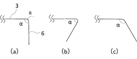
- an example of an L shape is schematically shown in a partial sectional view in FIG. 1
- an example of a Z shape is schematically shown in a partial sectional view in FIG.
- the radius of curvature of the bent flange portion is R.
- the angle ⁇ formed by the flat plate portion 3 and the bending flange portion 6 is divided into a right angle (a), an acute angle (b) and an obtuse angle (c), and the Z shape shown in FIG.
- the bending patterns of ⁇ and ⁇ are both right angle (a), ⁇ is right angle and ⁇ are obtuse angles (b), ⁇ is right angle and ⁇ are acute angles (c), ⁇ is obtuse angle and ⁇ are right angles (d), and ⁇ is Acute and ⁇ are right angles (e), ⁇ is obtuse and ⁇ is obtuse (f), ⁇ is obtuse and ⁇ is acute (g), ⁇ is acute and ⁇ is obtuse (h), and ⁇ and ⁇ are acute (i). ).
- the product shape is pressed by forming including overhang forming.
- the flat plate portion 3 is appropriately pressed by a cushion pad or the like so as not to float during molding.
- the blanking step before the blanking step, first, a place where a large amount of material inflows in the conventional press molding is specified, and a blank shape with a surplus portion on the outer shape of the expanded shape of the press molded product is determined (blank shape).
- the blank step may be performed by blanking the determined blank shape from a plate-shaped material (blank step). By doing so, it is possible to perform press molding with higher material yield and higher processing accuracy.
- the place where the material is excessively flowed in in press molding is specified.
- the material inflow may be measured by measuring the material inflow with a press-molded product or by CAE (Computer Aided Engineering).
- the blank shape of the plate-shaped material for removing the outer shape is determined by adding a surplus portion to the specified material inflow portion.
- the determined extra thickness portion includes the length of the bending flange portion required for bending.
- the shape to be bent in the first pressing step is a Z shape in which the bending flange portion is bent along two ridges (straight sides) or a shape in which a plurality of Z shapes are combined, and It is preferable that the bent flat vertical wall portion is stretched in the height direction in the second pressing step. By doing so, press molding with higher processing accuracy can be performed.
- the height h2 of the flat vertical wall portion of the bending flange portion in the direction orthogonal to the bending flange is extended from the height h1 designed in the first pressing step (FIG. 11). reference).
- the difference ⁇ h is preferably 0.2 to 1.0% of the representative length L of the flat plate portion.
- the flat plate portion representative length L is a length when a perpendicular line drawn from the center of the overhanging portion to the bending flange is projected on a plane including the flat plate portion (see FIGS. 10 and 21).
- the reason for stretching the flat vertical wall portion of the bending flange in the second pressing step is as follows. Since the flat plate portion after the first press molding is slightly bent, and the deflection that cannot be eliminated by the overhanging in the second press step remains in the flat plate portion, by allowing the flat plate portion to entirely flow into the bending flange side, This is to eliminate the deflection. If the stretching amount ⁇ h of the flat vertical wall portion is less than the lower limit, the above effect is not exhibited, while if it exceeds the upper limit, cracks may occur in the overhang portion.
- the excess thickness part including the bent flange part and the extension part of the flat vertical wall added in the second pressing process is trimmed and removed according to the external shape of the product.
- the present invention can be suitably applied to high strength steel plates.
- the springback becomes large, so the effect of applying the present invention is high.
- Example 1 Schematically, the present embodiment was applied to a part in which 300 mm ⁇ 300 mm rectangular blank was subjected to frustoconical (height 3 mm) overhang molding in the direction perpendicular to the plane.
- the material is a 980 MPa cold-rolled steel sheet (Hi-Ten), the plate thickness is 0.9 mm, and the mechanical properties are a yield point (YP) of 620 MPa, a tensile strength (TS) of 1030 MPa, and an elongation (El) of 15. %Met.
- Fig. 3 shows the shape of the press-formed product 1 in a perspective view.
- a frustoconical protrusion 2 is formed in the center of the rectangular shape in the direction perpendicular to the surface.
- a flat plate portion 3 is provided around the overhang portion 2, a circular bottom surface (punch bottom) 4 is provided at the center of the overhang portion, and a vertical wall (side wall) 5 is provided around the circular bottom surface 4.
- the sides of the rectangular flat plate are the X and Y axes, and the coordinate system is perpendicular to the flat plate portion 3 and the direction in which the protrusion 2 is convex is the positive Z axis.
- the flat plate portion 3 is distorted due to springback as shown in FIG. In FIG. 4, it can be seen that the press-formed product 101 after springback is distorted from the edge shape 102 at the bottom dead center of the forming process in the Z direction.
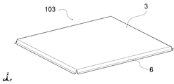
- FIG. 5 shows a perspective view of the intermediate molded product 103 after applying the present embodiment and folding the bending flange portion 6 into the extra thickness portion in the first pressing step.
- the fold line matches (circumscribes) the contour outline of the product.
- Each corner of the rectangle is cut out during blanking (outer shape cutting) so that the flat plate portion 3 is not deformed during bending.
- FIG. 6 shows a perspective view of a press-formed product 104 which is subjected to bulging by the second press-molding and in which a truncated cone-shaped bulged portion 2 is provided at the center of the intermediate molded product.
- the restraint of the bent portion 6 suppresses the material inflow at the time of bulging, and the flat plate portion 3 does not show the twist due to the spring back (see FIG. 4) unlike the conventional method.
- the flat plate portion 3 is trimmed so as to have the rectangular shape shown in FIG. 3, and the final product is obtained.
- Fig. 7 shows an example of the amount of springback after press-molding this part by the conventional method with contour lines.
- positive (+) displacement in the Z-axis direction is indicated by (+) and negative displacement is indicated by ( ⁇ ).
- the amount of splattering or sagging is large at the center of the side of the rectangular flat plate 3 outline.
- the amount of shaving (+displacement) is up to 1.5 mm, and the sagging amount (-displacement) is up to 1.9 mm. there were.
- FIG. 8 shows an example of the springback amount of a press-formed product to which the present invention is applied, by contour lines.
- the notation of displacement in the Z-axis direction is the same as in FIG. 7.
- Rectangle flat plate part 3 There is almost no distortion on the side of the outline, the displacement contours in the Z direction are close to concentric circles, the amount of splash (+ displacement) is 0.5 mm at maximum, and the amount of depression (- displacement) is at maximum. It was within 0.4mm. It can be seen that the distortion of the panel is significantly improved in the method of the present invention as compared with the conventional method.
- FIG. 9 is a contour diagram showing the X-direction displacement amount when press molding is performed by the conventional method.
- a positive (toward the right in FIG. 9) displacement in the X direction is represented by (+)
- a negative (toward the left in FIG. 9) displacement is represented by ( ⁇ ).
- the amount of material inflow can be evaluated from the amount of displacement after molding. Since this component has a vertically and horizontally symmetrical shape and there is almost no difference in the inflow amount in each direction, this embodiment is applied to the entire circumference.
- the steps after the blanking step are the same as in Example 1.
- FIG. 10 is a perspective view of a press-formed product 104 that has been subjected to bulge-forming by the second press-molding and in which a truncated cone-shaped bulged portion 2 is provided in the center of the intermediate-formed product.
- the restraint of the bent portion 6 suppresses the material inflow at the time of bulging, and the flat plate portion 3 does not show the twist due to the spring back (see FIG. 4) unlike the conventional method.
- the flat plate portion representative length L shown in FIG. 10 is a length when a perpendicular line drawn from the center of the overhanging portion 2 to the bending flange 6 is projected onto a plane including the flat plate portion 3.
- FIG. 11A is a schematic partial cross-sectional view showing the state of the flat vertical wall portion 61 of the Z-shaped bent portion after the first pressing step
- FIG. 11B is the Z-shaped bent portion after the second pressing step.
- the flat plate portion 3 is trimmed so as to have the rectangular shape shown in FIG. 3 to obtain the final product.
- FIG. 12 shows an example of the amount of springback of the press-formed product in this example by contour lines.
- the notation of displacement in the Z-axis direction is the same as in FIG. 7.
- Rectangle flat plate part 3 There is almost no distortion on the side of the outline, the displacement contours in the Z direction are close to concentric circles, the amount of splash (+ displacement) is within 0.3 mm at the maximum, and the amount of depression (- displacement) was within 0.3 mm at maximum. It can be seen that the distortion of the panel is significantly improved in the method of the present invention as compared with the conventional method.
- Example 4 Next, the present embodiment was applied to the molding of the A-pillar lower inner of the actual part. It is a component having an approximate length of 700 mm and a width of 400 mm.
- the material is 980 MPa cold-rolled steel sheet (Hi-Ten), the plate thickness is 1.2 mm, and the mechanical properties are a yield point (YP) of 620 MPa, a tensile strength (TS) of 1030 MPa, and an elongation (El) of 15. %Met.
- Fig. 13 shows a perspective view of the shape of the press-formed product 1.
- the width on the right side in the longitudinal direction is large, and the protrusion 2 in the direction perpendicular to the plane is provided near the center of the width on the right side.
- the flat plate portion 3 is an XY plane, the longitudinal direction is the rightward X axis, and the width direction is the upward Y axis.
- a coordinate system is used in which the direction in which the protrusion 2 is convex to the flat plate surface is the positive Z axis. To do. Same below.
- the step portion 7 having a Z-shaped cross section is provided on the front side (the side having the smaller Y value).
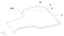
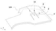
- FIG. 15 is a perspective view of an intermediate molded product 103 obtained by applying the press molding method according to the present invention to this component and performing Z-shaped bending (FIG. 2A) in the first pressing step. .. Since the material of the present embodiment has a large material inflow around the overhanging shape, in FIG. 15, a bending line 8 composed of straight sides is formed in parallel with the straight outline line 9 on the right side of the product (the side on which the X value is large). However, for the contour line 9 on the right side of the upper part of the component (the side on which the Y value is large, the side on which the X value is large), the bending line 8 as the straight side is approximated by three straight lines. There is.
- step processing is performed in advance on the near side (side having a smaller Y value) before the first press molding.
- FIG. 16 shows a perspective view of a press-formed product 104 obtained by subjecting the above intermediate-formed product to bulging by the second press-forming. After that, the excess thickness portion 10 is trimmed along the contour outline 9 of the product to obtain the press-formed product 1 shown in FIG.
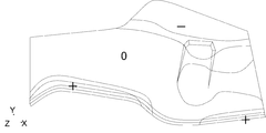
- FIG. 17 shows a contour map of the amount of springback after press molding by the conventional method
- FIG. 18 shows a contour map of the amount of springback after press molding by the press molding method according to the present invention.
- Both are top views, and the springback amount is evaluated by the displacement in the Z direction.
- the notation of displacement in the Z-axis direction is the same as in FIG. 7.
- the springback amount was 3.8 mm at the maximum for the amount of fluff (displacement of +) and 7.1 mm at the maximum for amount of depression (displacement of ⁇ ).
- the press molding method according to the present invention was applied, the amount of splash (+ displacement) was improved to a maximum of 3.4 mm, and the amount of depression (displacement of ⁇ ) was improved to a maximum of 3.9 mm.
- Example 5 In applying the present embodiment to a press-formed product similar to that in Example 4, a portion where a large amount of material flows in the press-forming was specified in advance.
- FIG. 19 is a contour diagram showing the X-direction displacement amount when the present component is press-molded by the conventional method
- FIG. 20 is the Y-direction displacement amount similarly. Positive displacement is indicated by (+) and negative displacement is indicated by (-). Since the material inflow amount is large on the right side of the upper part of the component (the side where the X value is large on the side where the Y value is large) and the front side (the side where the X value is large), the present embodiment is applied to the right side and the front side of the upper part of the component, and the surplus Parts are given. The steps after the blanking step are the same as in Example 1.
- FIG. 21 shows a perspective view of a press-formed product 104 obtained by subjecting the above-mentioned intermediate-formed product to stretch molding by the second press-forming.
- the flat plate portion representative length L is the length when the perpendiculars drawn from the center of the overhanging portion 2 to the bending flange 6 are projected onto the plane including the flat plate portion 3.
- the excess thickness portion 10 is trimmed along the contour outline 9 of the product to obtain the press-formed product 1 shown in FIG.
- FIG. 22 shows a contour map of the amount of springback after press molding by the press molding method according to the present invention.
- FIG. 22 is a top view, and the springback amount is evaluated by the displacement in the Z direction. The notation of displacement in the Z-axis direction is the same as in FIG. 7.
- the springback amount in the conventional method shown in FIG. 17 was 3.8 mm at maximum for the amount of fluff (displacement of +) and 7.1 mm at maximum for amount of depression (displacement of ⁇ ).
- the press molding method according to the present invention was applied, the amount of fluff (displacement of +) was improved to 3.0 mm at maximum, and the amount of depression (displacement of ⁇ ) was improved to 3.2 mm at maximum.
- the press molding method, the blank material of the plate-shaped material, the manufacturing method of the press molded product and the press molded product of the present invention are not limited to the above examples, and the scope of claims is not limited.
- the shape of the press-molded product may be other than that shown in FIGS. 2 and 13, and the shape of the bent flange portion may be other than that shown in FIGS. 5 and 15, for example.
- the press-molding method the blank material of the plate-shaped material, the press-molded intermediate molded product, the press-molded product manufacturing method, and the press-molded product of the present invention, springback can be efficiently suppressed.
- the technique of the present invention is suitable for application to parts in which material influx during press molding affects molding accuracy.
Landscapes
- Engineering & Computer Science (AREA)
- Mechanical Engineering (AREA)
- Shaping Metal By Deep-Drawing, Or The Like (AREA)
- Punching Or Piercing (AREA)
Abstract
Description
(1)形状剛性が低い部品に対して,スプリングバック抑制に有効なプレス成形工法であること。
(2)部品の形状によらず適用可能なプレス成形工法であること。
上記課題を有利に解決する本発明のプレス成形方法は、張出部を有するプレス成形品を板状材料からプレス成形する方法において、上記板状材料が余肉部を有し、上記余肉部を直辺で折り曲げ、曲げフランジ部を有する中間成形品とする第1のプレス工程と、上記中間成形品に上記張出部を設ける張出加工を含むプレス成形を施す第2のプレス工程と、を含むことを特徴としている。
(a)上記第1のプレス工程の前に、予め特定したプレス成形時の材料流入量に応じて、上記プレス成形品の展開形状の輪郭外形に余肉部を設けるブランク形状を決定するブランク形状の決定工程を有すること、
(b)上記曲げフランジ部の断面をL形またはZ形とすること、
(c)上記曲げフランジ部の断面をZ形とし、上記第1のプレス工程で折り曲げられた平坦縦壁部を、上記第2のプレス工程において高さ方向に延伸すること、
(d)上記平坦縦壁部の延伸された高さΔhを、対応する曲げフランジ部に接続する平板部の代表長さLの0.2~1.0%とする、ここで、平板部の代表長さLとは、張出部中央から曲げフランジにおろした垂線を、平板部を含む平面に投影したときの長さであること、
(e)上記第1のプレス工程では、上記余肉部を、上記プレス成形品の展開形状の輪郭外形線に対し外接、または離隔した直辺で折り曲げること、
などが好ましい解決手段になり得るものと考えられる。
(a)上記ブランク工程の前に、予め特定したプレス成形時の材料流入量に応じて、上記プレス成形品の展開形状の輪郭外形に余肉部を設けるブランク形状を決定するブランク形状の決定工程を有すること、
(b)上記曲げフランジ部の断面をL形またはZ形とすること、
(c)上記曲げフランジ部の断面をZ形とし、上記第1のプレス工程で折り曲げられた平坦縦壁部を、上記第2のプレス工程において高さ方向に延伸すること、
(d)上記平坦縦壁部の延伸された高さΔhを、対応する曲げフランジ部に接続する平板部の代表長さLの0.2~1.0%とする、ここで、平板部の代表長さLとは、張出部中央から曲げフランジにおろした垂線を、平板部を含む平面に投影したときの長さであること、
(e)上記第1のプレス工程では、上記余肉部を、上記プレス成形品の展開形状の輪郭外形線に対し外接、または離隔した直辺で折り曲げること、
などが好ましい解決手段になり得るものと考えられる。
模式的に、300mm×300mm矩形ブランクの中央に、円錐台形状(高さ3mm)の張出成形を面直方向に施す部品に本実施形態を適用した。材料は、980MPa級冷間圧延鋼板(ハイテン)で、板厚が0.9mmであり、機械特性は、降伏点(YP)が620MPa、引張強さ(TS)が1030MPa、伸び(El)が15%であった。
実施例1と同様のプレス成形品に本実施形態を適用するにあたり、予め、プレス成形における材料流入が多い個所を特定した。図9に従来法でプレス成形した場合のX方向変位量を等高線図で示す。図9において、X方向の正(図9の右方向に向かう)の変位を(+)、負(図9の左方向に向かう)の変位を(-)で表す。この成形後の変位量から材料流入量を評価できる。本部品では、上下左右対称の形状であり、各方向の流入量に差がほとんどないため、全周に本実施形態を適用した。ブランク工程以降は実施例1と同様である。
実施例1と同様のプレス成形品に本実施形態を適用するにあたり、曲げフランジをZ形とし、第1のプレス工程で折り曲げられた平坦縦壁部を、第2のプレス工程において高さ方向に延伸した。図10に第2のプレス成形により、張出成形を施し、中間成形品の中央部に円錐台形状の張出部2を設けたプレス成形品104の斜視図を示す。折り曲げ部6の拘束により、張出成形時の材料流入が抑止され、平板部3には、従来法のようなスプリングバックによるねじれ(図4参照)は見られない。図10に示す平板部代表長さLは、張出部2中央から曲げフランジ6におろした垂線を、平板部3を含む平面に投影したときの長さである。
次に、実部品のAピラーロアインナーの成形に本実施形態を適用した。概略長さ700mm×幅400mmの部品である。材料は、980MPa級冷間圧延鋼板(ハイテン)で、板厚が1.2mmであり、機械特性は、降伏点(YP)が620MPa、引張強さ(TS)が1030MPa、伸び(El)が15%であった。
実施例4と同様のプレス成形品に本実施形態を適用するにあたり、予め、プレス成形における材料流入が多い個所を特定した。図19には、本部品を従来法でプレス成形したときのX方向変位量を等高線図で、図20には、同じくY方向変位量を等高線図で示す。それぞれ、正の変位を(+)、負の変位を(-)で示す。部品上部右側(Y値が大きい辺のX値が大きい側)と前方側(X値が大きい辺)の材料流入量が多いため、部品上部右側と前方側に本実施形態を適用し、余肉部を付与した。ブランク工程以降は実施例1と同様である。
実施例4と同様のプレス成形品に本実施形態を適用するにあたり、曲げフランジをZ形とし、第1のプレス工程で折り曲げられた平坦縦壁部を、第2のプレス工程において高さ方向に延伸した。図21に第2のプレス成形により、上記中間成形品に張出成形を施したプレス成形品104の斜視図を示す。ここで、平板部代表長さLは、張出部2中央からそれぞれ曲げフランジ6におろした垂線を、平板部3を含む平面に投影したときの長さである。実施例3と同様、第2のプレス工程において、曲げフランジ部の平坦縦壁部の、曲げフランジに直交する方向の高さh2=3.5mmとして、第1のプレス工程において設計する高さh1=3.0mmより延伸して設計した。その差Δh=0.5mmは、平板部代表長さL=200~250mmの0.20~0.25%であった。
2 張出部
3 平板部
4 パンチ底(底面)
5 縦壁(側壁)
6 曲げフランジ部
61 平坦縦壁部
7 ステップ部
8 折り曲げ線
9 製品の輪郭外形線
10 余肉部
101 スプリングバック後のプレス成形品
102 成形下死点のエッジ形状
103 曲げ成形後の中間成形品
104 張出成形後のプレス成形品
Claims (17)
- 張出部を有するプレス成形品を板状材料からプレス成形する方法において、
前記板状材料が余肉部を有し、該余肉部を直辺で折り曲げ、曲げフランジ部を有する中間成形品とする第1のプレス工程と、
前記中間成形品に前記張出部を設ける張出加工を含むプレス成形を施す第2のプレス工程と、
を含むことを特徴とするプレス成形方法。 - 前記第1のプレス工程の前に、
予め特定したプレス成形時の材料流入量に応じて、前記プレス成形品の展開形状の輪郭外形に余肉部を設けるブランク形状を決定するブランク形状の決定工程を有することを特徴とする請求項1に記載のプレス成形方法。 - 前記曲げフランジ部の断面をL形またはZ形とすることを特徴とする請求項1または2に記載のプレス成形方法。
- 前記曲げフランジ部の断面をZ形とし、
前記第1のプレス工程で折り曲げられた平坦縦壁部を、前記第2のプレス工程において高さ方向に延伸することを特徴とする請求項1または2に記載のプレス成形方法。 - 前記平坦縦壁部の延伸された高さΔhを、対応する曲げフランジ部に接続する平板部の代表長さLの0.2~1.0%とする、ここで、平板部の代表長さLとは、張出部中央から曲げフランジにおろした垂線を、平板部を含む平面に投影したときの長さであることを特徴とする請求項4に記載のプレス成形方法。
- 前記第1のプレス工程では、前記余肉部を、前記プレス成形品の展開形状の輪郭外形線に対し外接、または離隔した直辺で折り曲げることを特徴とする請求項1~5のいずれか1項に記載のプレス成形方法。
- 請求項1~6のいずれか一項に記載のプレス成形方法の余肉部を有する板状材料のブランク材。
- 前記余肉部が、隣り合う前記直辺の接続部に切り欠きを有することを特徴とする請求項7に記載の板状材料のブランク材。
- 請求項1または2に記載のプレス成形方法における前記中間成形品であって、
余肉部に直辺で折り曲げられた曲げフランジ部を有することを特徴とする中間成形品。 - 前記曲げフランジ部の断面がL形またはZ形であることを特徴とする請求項9に記載の中間成形品。
- 張出部を有するプレス成形品を板状材料から製造する方法であって、
前記プレス成形品の展開形状の外形に余肉部を付して前記板状材料から抜き加工するブランク工程と、
前記余肉部を直辺で折り曲げ、曲げフランジ部を有する中間成形品とする第1のプレス工程と、
前記中間成形品に前記張出部を設ける張出加工を含むプレス成形を施す第2のプレス工程と、
前記余肉部をトリミングするトリミング工程と、
を含むことを特徴とするプレス成形品の製造方法。 - 前記ブランク工程の前に、
予め特定したプレス成形時の材料流入量に応じて、前記プレス成形品の展開形状の輪郭外形に余肉部を設けるブランク形状を決定するブランク形状の決定工程を有することを特徴とする請求項11に記載のプレス成形品の製造方法。 - 前記曲げフランジ部の断面をL形またはZ形とすることを特徴とする請求項11または12に記載のプレス成形品の製造方法。
- 前記曲げフランジ部の断面をZ形とし、
前記第1のプレス工程で折り曲げられた平坦縦壁部を、前記第2のプレス工程において高さ方向に延伸することを特徴とする請求項11または12に記載のプレス成形品の製造方法。 - 前記平坦縦壁部の延伸された高さΔhを、対応する曲げフランジ部に接続する平板部の代表長さLの0.2~1.0%とする、ここで、平板部の代表長さLとは、張出部中央から曲げフランジにおろした垂線を、平板部を含む平面に投影したときの長さであることを特徴とする請求項14に記載のプレス成形品の製造方法。
- 前記第1のプレス工程では、前記余肉部を、前記プレス成形品の展開形状の輪郭外形線に対し外接、または離隔した直辺で折り曲げることを特徴とする請求項11~15のいずれか1項に記載のプレス成形品の製造方法。
- 請求項1~6のいずれか一項に記載のプレス成形方法でプレス成形されることを特徴とするプレス成形品。
Priority Applications (6)
| Application Number | Priority Date | Filing Date | Title |
|---|---|---|---|
| CN201980088564.6A CN113286672B (zh) | 2019-01-11 | 2019-12-09 | 冲压成形方法、板状材料的落料、中间成形品、冲压成形品的制造方法和冲压成形品 |
| KR1020217018986A KR102499437B1 (ko) | 2019-01-11 | 2019-12-09 | 프레스 성형 방법, 판상 재료의 블랭크재, 중간 성형품, 프레스 성형품의 제조 방법 및 프레스 성형품 |
| JP2020509118A JP6702521B1 (ja) | 2019-01-11 | 2019-12-09 | プレス成形方法、板状材料のブランク材、中間成形品、プレス成形品の製造方法およびプレス成形品 |
| US17/417,217 US12115571B2 (en) | 2019-01-11 | 2019-12-09 | Press-forming method, blank member for sheet-shaped material, intermediate formed product, method for manufacturing press-formed product, and press-formed product |
| EP19909134.9A EP3909697B1 (en) | 2019-01-11 | 2019-12-09 | Press-forming method, method for manufacturing press-molded article |
| MX2021008365A MX2021008365A (es) | 2019-01-11 | 2019-12-09 | Metodo de moldeo por presion, elemento de pieza virgen para material en forma de lamina, producto intermedio formado, metodo para la fabricacion de producto moldeado por presion, y producto moldeado por presion. |
Applications Claiming Priority (6)
| Application Number | Priority Date | Filing Date | Title |
|---|---|---|---|
| JP2019-003819 | 2019-01-11 | ||
| JP2019003819 | 2019-01-11 | ||
| JP2019003793 | 2019-01-11 | ||
| JP2019-003793 | 2019-01-11 | ||
| JP2019160018 | 2019-09-03 | ||
| JP2019-160018 | 2019-09-03 |
Publications (1)
| Publication Number | Publication Date |
|---|---|
| WO2020144995A1 true WO2020144995A1 (ja) | 2020-07-16 |
Family
ID=71520722
Family Applications (1)
| Application Number | Title | Priority Date | Filing Date |
|---|---|---|---|
| PCT/JP2019/048026 Ceased WO2020144995A1 (ja) | 2019-01-11 | 2019-12-09 | プレス成形方法、板状材料のブランク材、中間成形品、プレス成形品の製造方法およびプレス成形品 |
Country Status (7)
| Country | Link |
|---|---|
| US (1) | US12115571B2 (ja) |
| EP (1) | EP3909697B1 (ja) |
| JP (1) | JP6702521B1 (ja) |
| KR (1) | KR102499437B1 (ja) |
| CN (1) | CN113286672B (ja) |
| MX (1) | MX2021008365A (ja) |
| WO (1) | WO2020144995A1 (ja) |
Cited By (2)
| Publication number | Priority date | Publication date | Assignee | Title |
|---|---|---|---|---|
| JP2023046870A (ja) * | 2021-09-24 | 2023-04-05 | 日本製鉄株式会社 | 成形体、ブランク、成形体製造方法、及び金型 |
| WO2024171556A1 (ja) * | 2023-02-15 | 2024-08-22 | Jfeスチール株式会社 | プレス成形品の製造方法、及び金型の設計方法 |
Families Citing this family (2)
| Publication number | Priority date | Publication date | Assignee | Title |
|---|---|---|---|---|
| CN112246936B (zh) * | 2020-09-28 | 2022-09-02 | 常熟市宏达商业设施有限公司 | 一种辊轧机 |
| CN119657757B (zh) * | 2024-12-13 | 2025-10-21 | 东风汽车股份有限公司 | 一种拉延翻边模具及控制钣金件翻边回弹方法 |
Citations (6)
| Publication number | Priority date | Publication date | Assignee | Title |
|---|---|---|---|---|
| JPS547862B2 (ja) * | 1974-10-26 | 1979-04-10 | ||
| JPH0237248B2 (ja) * | 1981-12-05 | 1990-08-23 | Toyota Motor Co Ltd | |
| JPH11277155A (ja) | 1998-03-30 | 1999-10-12 | Topre Corp | プレス成形品の平面度矯正方法 |
| JP2009255117A (ja) | 2008-04-15 | 2009-11-05 | Nippon Steel Corp | 形状凍結性に優れたプレス成形方法およびその装置 |
| JP2013169578A (ja) * | 2012-02-22 | 2013-09-02 | Topre Corp | プレス部品の成形方法 |
| JP6176430B1 (ja) | 2016-03-01 | 2017-08-09 | Jfeスチール株式会社 | プレス成形品の製造方法 |
Family Cites Families (14)
| Publication number | Priority date | Publication date | Assignee | Title |
|---|---|---|---|---|
| AU529459B2 (en) | 1979-05-22 | 1983-06-09 | Tate Architectural Products Inc. | Load bearing panels |
| JPH0751761A (ja) | 1993-08-18 | 1995-02-28 | Nkk Corp | 爆轟圧によるパネル部品の製造方法 |
| JP3547862B2 (ja) | 1995-09-08 | 2004-07-28 | 本田技研工業株式会社 | 折曲フランジを有する絞り成形品の成形方法 |
| US6877349B2 (en) | 2000-08-17 | 2005-04-12 | Industrial Origami, Llc | Method for precision bending of sheet of materials, slit sheets fabrication process |
| CN1954934A (zh) | 2005-10-25 | 2007-05-02 | 比亚迪股份有限公司 | 防止零件翻边后回弹的方法 |
| ES2600402T3 (es) * | 2010-11-24 | 2017-02-08 | Nippon Steel & Sumitomo Metal Corporation | Método para fabricar un producto con forma de L |
| JP6006656B2 (ja) * | 2012-05-28 | 2016-10-12 | 東プレ株式会社 | 熱間プレス製品の成形方法および熱間プレス製品の製造方法 |
| WO2014185428A1 (ja) | 2013-05-13 | 2014-11-20 | 新日鐵住金株式会社 | ブランク、成形板、プレス成形品の製造方法及びプレス成形品 |
| JP5664810B1 (ja) | 2013-06-27 | 2015-02-04 | Jfeスチール株式会社 | プレス成形方法及び装置 |
| BR112017013317A2 (ja) * | 2014-12-22 | 2018-01-02 | Nippon Steel & Sumitomo Metal Corporation | A manufacturing method of a hat form cross section article |
| US10603707B2 (en) | 2015-03-31 | 2020-03-31 | Jfe Steel Corporation | Press-forming method, method of manufacturing component with the press-forming method and component manufactured with the press-forming method |
| JP6052478B1 (ja) | 2015-06-16 | 2016-12-27 | Jfeスチール株式会社 | 伸びフランジ成形部品の製造方法 |
| MX367318B (es) | 2015-08-28 | 2019-08-15 | Jfe Steel Corp | Metodo para la fabricacion de un componente en forma de brida estirada. |
| WO2017149955A1 (ja) | 2016-03-01 | 2017-09-08 | Jfeスチール株式会社 | プレス成形品の製造方法 |
-
2019
- 2019-12-09 MX MX2021008365A patent/MX2021008365A/es unknown
- 2019-12-09 US US17/417,217 patent/US12115571B2/en active Active
- 2019-12-09 CN CN201980088564.6A patent/CN113286672B/zh active Active
- 2019-12-09 KR KR1020217018986A patent/KR102499437B1/ko active Active
- 2019-12-09 WO PCT/JP2019/048026 patent/WO2020144995A1/ja not_active Ceased
- 2019-12-09 JP JP2020509118A patent/JP6702521B1/ja active Active
- 2019-12-09 EP EP19909134.9A patent/EP3909697B1/en active Active
Patent Citations (6)
| Publication number | Priority date | Publication date | Assignee | Title |
|---|---|---|---|---|
| JPS547862B2 (ja) * | 1974-10-26 | 1979-04-10 | ||
| JPH0237248B2 (ja) * | 1981-12-05 | 1990-08-23 | Toyota Motor Co Ltd | |
| JPH11277155A (ja) | 1998-03-30 | 1999-10-12 | Topre Corp | プレス成形品の平面度矯正方法 |
| JP2009255117A (ja) | 2008-04-15 | 2009-11-05 | Nippon Steel Corp | 形状凍結性に優れたプレス成形方法およびその装置 |
| JP2013169578A (ja) * | 2012-02-22 | 2013-09-02 | Topre Corp | プレス部品の成形方法 |
| JP6176430B1 (ja) | 2016-03-01 | 2017-08-09 | Jfeスチール株式会社 | プレス成形品の製造方法 |
Non-Patent Citations (1)
| Title |
|---|
| See also references of EP3909697A4 |
Cited By (4)
| Publication number | Priority date | Publication date | Assignee | Title |
|---|---|---|---|---|
| JP2023046870A (ja) * | 2021-09-24 | 2023-04-05 | 日本製鉄株式会社 | 成形体、ブランク、成形体製造方法、及び金型 |
| JP7695542B2 (ja) | 2021-09-24 | 2025-06-19 | 日本製鉄株式会社 | 成形体、ブランク、成形体製造方法、及び金型 |
| WO2024171556A1 (ja) * | 2023-02-15 | 2024-08-22 | Jfeスチール株式会社 | プレス成形品の製造方法、及び金型の設計方法 |
| JP7605372B1 (ja) * | 2023-02-15 | 2024-12-24 | Jfeスチール株式会社 | プレス成形品の製造方法、及び金型の設計方法 |
Also Published As
| Publication number | Publication date |
|---|---|
| US12115571B2 (en) | 2024-10-15 |
| EP3909697B1 (en) | 2026-01-28 |
| JP6702521B1 (ja) | 2020-06-03 |
| US20220048088A1 (en) | 2022-02-17 |
| EP3909697A1 (en) | 2021-11-17 |
| KR20210092295A (ko) | 2021-07-23 |
| MX2021008365A (es) | 2021-08-05 |
| KR102499437B1 (ko) | 2023-02-13 |
| JPWO2020144995A1 (ja) | 2021-02-18 |
| CN113286672B (zh) | 2023-04-21 |
| EP3909697A4 (en) | 2022-03-02 |
| CN113286672A (zh) | 2021-08-20 |
Similar Documents
| Publication | Publication Date | Title |
|---|---|---|
| JP6702521B1 (ja) | プレス成形方法、板状材料のブランク材、中間成形品、プレス成形品の製造方法およびプレス成形品 | |
| CN109414745B (zh) | 冲压部件的制造方法及制造装置 | |
| TWI448338B (zh) | 具有l字狀形狀之零件的壓製成形方法 | |
| EP3760330B1 (en) | Metal plate for press molding, press molding device, and production method for pressed component | |
| KR101814943B1 (ko) | 프레스 성형품 및 프레스 성형품의 제조 방법 및 프레스 성형품의 제조 장치 | |
| JP6631759B1 (ja) | プレス部品の製造方法、プレス成形装置及びプレス成形用の金属板 | |
| US20180185899A1 (en) | Method and apparatus for manufacturing press component | |
| JP2009241109A (ja) | チャンネル部材の曲げ成形方法 | |
| CN115397577A (zh) | 冲压成形方法以及冲压成形件 | |
| WO2016203904A1 (ja) | 伸びフランジ成形部品の製造方法 | |
| JP2020124726A (ja) | プレス成形品及びプレス加工方法 | |
| JP2023177203A (ja) | プレス成形方法及びプレス成形品の製造方法 | |
| JPWO2019187863A1 (ja) | プレス成形品の設計方法、プレス成形金型、プレス成形品およびプレス成形品の製造方法 | |
| JP7525817B1 (ja) | 構造部材及びその製造方法 | |
| JP7006666B2 (ja) | プレス成形品の設計方法、プレス成形品およびプレス成形品の製造方法 | |
| JP2021176646A (ja) | プレス部品の製造方法、プレス成形用の金属板、及び高張力鋼板 | |
| JP7188567B2 (ja) | ブランクおよび部品 | |
| JP7205520B2 (ja) | プレス部品の製造方法及びプレス成形用の金属板 | |
| JP7509278B1 (ja) | プレス成形方法、プレス成形品の製造方法、中間成形品およびプレス成形金型 | |
| WO2017195795A1 (ja) | 構造体及びその製造方法 | |
| JP7239048B1 (ja) | プレス成形方法及びプレス成形品の製造方法 | |
| JP7647714B2 (ja) | プレス成形方法及びプレス成形品の製造方法 | |
| JP2024001837A (ja) | プレス成形方法及びプレス成形品の製造方法 | |
| JP2024006554A (ja) | プレス成形品の製造方法 | |
| JP2021186833A (ja) | プレス成形品の剛性評価方法、形状決定方法およびプレス成形品 |
Legal Events
| Date | Code | Title | Description |
|---|---|---|---|
| ENP | Entry into the national phase |
Ref document number: 2020509118 Country of ref document: JP Kind code of ref document: A |
|
| 121 | Ep: the epo has been informed by wipo that ep was designated in this application |
Ref document number: 19909134 Country of ref document: EP Kind code of ref document: A1 |
|
| ENP | Entry into the national phase |
Ref document number: 20217018986 Country of ref document: KR Kind code of ref document: A |
|
| NENP | Non-entry into the national phase |
Ref country code: DE |
|
| ENP | Entry into the national phase |
Ref document number: 2019909134 Country of ref document: EP Effective date: 20210811 |
|
| WWG | Wipo information: grant in national office |
Ref document number: MX/A/2021/008365 Country of ref document: MX |
|
| WWG | Wipo information: grant in national office |
Ref document number: 2019909134 Country of ref document: EP |