WO2020145012A1 - タイヤの摩耗測定装置 - Google Patents
タイヤの摩耗測定装置 Download PDFInfo
- Publication number
- WO2020145012A1 WO2020145012A1 PCT/JP2019/048559 JP2019048559W WO2020145012A1 WO 2020145012 A1 WO2020145012 A1 WO 2020145012A1 JP 2019048559 W JP2019048559 W JP 2019048559W WO 2020145012 A1 WO2020145012 A1 WO 2020145012A1
- Authority
- WO
- WIPO (PCT)
- Prior art keywords
- tire
- steel wire
- magnetic
- measuring device
- tire wear
- Prior art date
- Legal status (The legal status is an assumption and is not a legal conclusion. Google has not performed a legal analysis and makes no representation as to the accuracy of the status listed.)
- Ceased
Links
Images
Classifications
-
- G—PHYSICS
- G01—MEASURING; TESTING
- G01B—MEASURING LENGTH, THICKNESS OR SIMILAR LINEAR DIMENSIONS; MEASURING ANGLES; MEASURING AREAS; MEASURING IRREGULARITIES OF SURFACES OR CONTOURS
- G01B7/00—Measuring arrangements characterised by the use of electric or magnetic techniques
- G01B7/26—Measuring arrangements characterised by the use of electric or magnetic techniques for measuring depth
-
- B—PERFORMING OPERATIONS; TRANSPORTING
- B60—VEHICLES IN GENERAL
- B60C—VEHICLE TYRES; TYRE INFLATION; TYRE CHANGING; CONNECTING VALVES TO INFLATABLE ELASTIC BODIES IN GENERAL; DEVICES OR ARRANGEMENTS RELATED TO TYRES
- B60C11/00—Tyre tread bands; Tread patterns; Anti-skid inserts
- B60C11/24—Wear-indicating arrangements
- B60C11/243—Tread wear sensors, e.g. electronic sensors
-
- G—PHYSICS
- G01—MEASURING; TESTING
- G01M—TESTING STATIC OR DYNAMIC BALANCE OF MACHINES OR STRUCTURES; TESTING OF STRUCTURES OR APPARATUS, NOT OTHERWISE PROVIDED FOR
- G01M17/00—Testing of vehicles
- G01M17/007—Wheeled or endless-tracked vehicles
- G01M17/02—Tyres
Definitions
- the present invention relates to a tire wear measuring device that measures a wear state of a tire and outputs information for displaying the wear state in real time or notifying that a predetermined wear amount has been reached, for example.
- Patent Document 1 describes a method of measuring a groove shape and wear of a tire by detecting a magnetic force emitted from a magnet inserted in a tread portion of the tire using a magnetic sensor provided inside the tire. ing.
- the measuring method described in Patent Document 1 measures the wear of the tire by detecting the magnetic force that decreases with the progress of wear of the tread portion with a magnetic sensor.
- this measuring method cannot accurately measure the wear of the tire if an external magnetic field exists in addition to the magnetic force from the magnet inserted in the tread portion.
- the magnetic force from the steel wire also causes a measurement error. For this reason, it is difficult to accurately measure the wear state of the tire by measuring with a magnetic sensor the magnetic force that decreases with the progress of wear of the tread portion.
- An object of the present invention is to provide a tire wear measuring device capable of accurately measuring the wear of a tire equipped with a steel wire while suppressing the influence of an external magnetic field.
- the present invention is a tire wear measuring device for measuring wear of a tread portion of a tire equipped with a steel wire, wherein a magnetic material embedded in the tread portion, a bias magnet for magnetizing the steel wire, and a magnetic force And a magnetic sensor for detecting.
- the bias magnet and the magnetic sensor are preferably provided on an inner surface of the tire, and the steel wire may be saturated with the bias magnet.
- the wire magnetizing direction in which the bias magnet magnetizes the steel wire may be an orthogonal direction orthogonal to the laminating direction in which the steel wire and the tread portion are laminated.
- the magnetization direction of the magnetic body that magnetizes the magnetic body may be orthogonal to the magnetization direction of the wire.
- the wire magnetization direction in which the bias magnet magnetizes the steel wire may be a stacking direction in which the steel wire and the tread portion are stacked.
- the magnetization direction of the magnetic body that magnetizes the magnetic body may be parallel to the magnetization direction of the wire.
- the tire wear measuring device includes two bias magnets, and may further include a yoke that connects the two bias magnets.
- the yoke can be used to concentrate the magnetic forces (magnetic fluxes) of the two bias magnets and efficiently magnetize the steel wire.
- the tire wear measuring device may further include a wireless communication means.
- the wireless communication means can transmit information regarding the measurement by the magnetic sensor to an external device such as a vehicle-side device.
- the bias magnet pre-magnetizes the steel wire, so that the magnetized state of the steel wire can be suppressed from being changed by the external magnetic field. This makes it possible to suppress the influence of the change in the magnetized state of the steel wire in the measurement of the magnetic force from the magnetic substance embedded in the tread portion, and to accurately measure the wear of the tread portion.
- FIG. 1(a) It is sectional drawing which shows typically the tire in which the tire wear measuring device which concerns on 1st Embodiment was provided, (b) The cross section which expands and shows the area
- (A) It is sectional drawing which shows typically the tire in which the tire wear measuring device which concerns on the modification of 1st Embodiment was provided, (b) The area
- FIG. (A) It is sectional drawing which shows typically the tire in which the tire wear measuring device which concerns on 2nd Embodiment was provided, (b) Section which expands and shows the area
- A It is sectional drawing which shows typically the tire in which the tire wear measuring device which concerns on the modification of 2nd Embodiment was provided,
- B The area
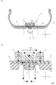
- FIG. 1A is a cross-sectional view schematically showing a tire 50 provided with a tire wear measuring device 10 according to this embodiment, and FIG. 1B is surrounded by a dashed line in FIG. 1A. It is sectional drawing which expands and shows the opened area.
- a tire wear measuring device 10 shown in FIGS. 1A and 1B measures wear of a tread portion 51 of a tire 50 including a steel wire 52, and includes a magnetic body 11 and a bias magnet. 12, a magnetic sensor 13 that detects the magnetic force of the magnetic body 11, and a wireless communication unit 14 that sends information measured by the magnetic sensor 13 to a vehicle-side device or the like.
- the magnetic body 11 is embedded in a part of the tread portion 51, and wears as the tread 51 wears. Therefore, the magnetic force formed by the magnetic body 11 becomes weaker as the tread portion 51 is worn. Therefore, the wear of the tread 51 can be evaluated by measuring the magnetic force from the magnetic body 11 with the magnetic sensor 13.
- the external magnetic field becomes noise when applied to the tire 50, and also becomes noise after being applied to the tire 50 by magnetizing the steel wire 52. That is, when the steel wire 52 is magnetized by the external magnetic field, the magnetic force from the steel wire 52 magnetized by the magnetic sensor 13 is measured by the magnetic sensor 13 even after the external magnetic field is removed. The magnetic force from the steel wire 52 becomes noise when measuring the magnetic force from the magnetic body 11 which decreases with wear of the tread portion 51. Further, since the steel wire 52 is located closer to the magnetic sensor 13 than the magnetic body 11 of the tread portion 51, the change in the magnetization state of the steel wire 52 affects the magnetic measurement emitted from the magnetic body 11. Is big.
- the tire wear measuring device 10 of this embodiment is provided with the bias magnet 12 for pre-magnetizing the steel wire 52.
- the bias magnet 12 for pre-magnetizing the steel wire 52.
- the magnetic force of the magnetic body 11 embedded in the tread portion 51 is emitted from the outside of the closed magnetic circuit.
- the magnetic sensor 13 measures a combination of the magnetic force from the steel wire 52 and the magnetic force from the magnetic body 11. By magnetizing the steel wire 52 with the bias magnet 12, the change in the magnetized state can be suppressed, so that the magnetic sensor 13 can accurately measure the magnetic force from the magnetic body 11.
- the steel wire 52 be saturated with the bias magnet 12. If the steel wire 52 is magnetically saturated, the magnetized state of the steel wire 52 can be kept constant and the magnetized state can be prevented from changing by an external magnetic field. That is, if the steel wire 52 is saturated and magnetized by the bias magnet 12, the magnetized state of the steel wire 52 does not change, so the magnetic sensor 13 can accurately measure the change in the magnetic force from the magnetic body 11.
- the bias magnet 12 is arranged so that the magnetic lines of force in the opposite direction reach the steel wire 52 and the magnetic poles of the opposite direction face the inner surface 53 of the tire 50.
- the bias magnet 12 arranged on the right side is arranged such that the end surface on the N pole side faces the inner side surface 53, and the bias magnet 12 arranged on the left side in FIG.
- the end surface on the S pole side is arranged so as to face the inner side surface 53.
- the wire magnetization direction that magnetizes the steel wire 52 is orthogonal to the stacking direction in which the steel wire 52 and the tread portion 51 are stacked (Y-axis direction) (X-axis direction, width direction of the tire 50). I am trying.
- the magnetic body magnetization direction that magnetizes the magnetic body 11 is the direction (Y-axis direction) orthogonal to the wire magnetization direction.
- the magnetic sensor 13 can accurately measure the change in the magnetic force from the magnetic body 11.
- the relationship between the wire magnetization direction and the magnetic body magnetization direction is not limited to this.
- the magnetic sensor 13 a sensor having a magnetoresistive effect element that measures magnetism and whose resistance changes according to the direction and strength of the magnetism is used.
- the magnetoresistive effect element include GMR element and TMR element.
- the measurement by the magnetic sensor 13 does not have to be continuously performed in real time, and may be intermittently performed at regular intervals. Alternatively, the measurement may be performed in response to an external instruction received via the wireless communication unit 14. By performing the measurement at regular time intervals or in response to an instruction, it is possible to suppress power consumption more than continuous measurement.
- a Hall element may be used as the magnetoresistive effect element which is the magnetic sensor 13 to measure the change in the magnetic flux intensity.
- the tire wear measuring device 10 includes a wireless communication unit 14 that outputs information about wear of the tire 50 based on the measurement of magnetism by the magnetic sensor 13 to a vehicle-side device (not shown).
- the wireless communication unit 14 can transmit the information of the measurement result by the magnetic sensor 13 to the vehicle side device or receive the information from the vehicle side device via the wireless communication. Transmission and reception of information by communication between the tire wear measuring device 10 and an external device is controlled by a CPU (not shown).
- the bias magnet 12, the magnetic sensor 13, and the wireless communication means 14 are provided on the inner side surface 53 of the tire 50 opposite to the tread portion 51.
- a method of installing these for example, a method of adhering each member to a predetermined position on the inner side surface 53 of the tire 50 using an acrylic adhesive can be mentioned.
- each member may be attached to another member and installed on the inner side surface 53 via the other member.
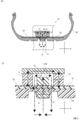
- [Modification] 2A is a sectional view schematically showing a tire 50 provided with a tire wear measuring device 20 according to a modified example of the present embodiment
- FIG. 2B is a dashed line in FIG. 2A. It is sectional drawing which expands and shows the enclosed area.
- the tire wear measuring device 20 is provided with a yoke 15 that connects the two bias magnets 12. By providing the yoke 15, the magnetic forces of the two bias magnets 12 can be concentrated and the steel wire 52 can be efficiently magnetized.
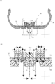
- FIG. 3A is a cross-sectional view schematically showing the tire 50 provided with the tire wear measuring device 30 according to the present embodiment, and FIG. 3B is surrounded by the one-dot chain line in FIG. 3A. It is sectional drawing which expands and shows the opened area.
- the bias magnet 12 is arranged so that the opposite magnetic pole faces the inner surface 53 of the tire 50.
- the bias magnet 12 arranged on the right side is arranged such that the end face on the N pole side faces the inner side surface 53
- the bias magnet 12 arranged on the left side is shown in FIG. 3B.
- the end surface on the N pole side is arranged so as to face the inner side surface 53.
- a wire magnetization direction for magnetizing the steel wire 52 is different from the tire wear measuring device 10 of the first embodiment in that it is a stacking direction (Y-axis direction) in which the steel wire 52 and the tread portion 51 are stacked.
- the magnetization direction of the magnetic body that magnetizes the magnetic body 11 is parallel to the magnetization direction of the wire. In this way, even if the magnetization direction of the magnetic body that magnetizes the magnetic body 11 is parallel to the magnetization direction of the wire, the influence of the external magnetic field on the magnetization state of the steel wire 52 can be suppressed. Therefore, like the tire wear measuring apparatus 10, the tire wear measuring apparatus 30 can accurately measure the change in the magnetic force from the magnetic body 11 due to the wear of the tread portion 51.
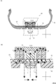
- FIG. 4A is a cross-sectional view schematically showing a tire 50 provided with a tire wear measuring device 40 according to a modification of the present embodiment
- FIG. 4B is a dashed-dotted line in FIG. 4A. It is sectional drawing which expands and shows the area
- the tire wear measuring device 40 is provided with a yoke 15 that connects the two bias magnets 12, and the yoke 15 is used to concentrate the magnetic force of the bias magnet 12.
- the present invention can be applied to a tire wear measuring device capable of measuring the wear state of a tire without visual inspection.
Landscapes
- Physics & Mathematics (AREA)
- General Physics & Mathematics (AREA)
- Engineering & Computer Science (AREA)
- Mechanical Engineering (AREA)
- Tires In General (AREA)
- Measurement Of Length, Angles, Or The Like Using Electric Or Magnetic Means (AREA)
Abstract
摩耗測定装置10は、トレッド部51に埋設された磁性体11と、スチールワイヤ52を磁化するバイアス磁石12と、磁性体11の磁力を検知する磁気センサ13とを備えており、バイアス磁石12によってスチールワイヤ52を予め磁化して外部磁場によるスチールワイヤ52の磁化状態の変化を抑制することで、磁気センサ13によるトレッド部51に埋設された磁性体11の磁力を精度良く測定できるから、スチールワイヤ52を備えているタイヤ50のトレッド部51の摩耗を外部磁場の影響を抑えて精度良く測定可能である。
Description
本発明は、タイヤの摩耗状態を測定し、例えば、リアルタイムで摩耗状態を表示したり、所定の摩耗量への到達を通知したりするための情報を出力する、タイヤの摩耗測定装置に関する。
タイヤの摩耗が進行すると、路面上を走行するときのグリップ性能が低下したり、濡れた路面上においてタイヤと路面との間の水を排出する排水機能が低下したりする。そこで、運転者や車両管理者は、溝に設けられたスリップサインなどに基づいてトレッドの摩耗状態を目視で点検し、安全性を確保するため使用限度を超える前にタイヤを交換する。
しかし、目視による点検は煩雑であり、また、トレッドの摩耗状態についての評価を誤るおそれもある。このような場合、性能が低下したタイヤが継続して使用されることになり、安全性の観点から好ましくない。
そこで、目視以外の方法によってタイヤの摩耗状態を点検する方法が提案されている。たとえば、特許文献1には、タイヤのトレッド部に挿入された磁石から放出される磁力をタイヤ内部に設けた磁気センサを用いて検知して、タイヤの溝形状や摩耗を測定する方法が記載されている。
しかし、目視による点検は煩雑であり、また、トレッドの摩耗状態についての評価を誤るおそれもある。このような場合、性能が低下したタイヤが継続して使用されることになり、安全性の観点から好ましくない。
そこで、目視以外の方法によってタイヤの摩耗状態を点検する方法が提案されている。たとえば、特許文献1には、タイヤのトレッド部に挿入された磁石から放出される磁力をタイヤ内部に設けた磁気センサを用いて検知して、タイヤの溝形状や摩耗を測定する方法が記載されている。
特許文献1に記載の測定方法は、トレッド部の摩耗進行に伴って減少する磁力を磁気センサで検知することによってタイヤの摩耗を測定する。しかし、この測定方法では、トレッド部に挿入された磁石からの磁力以外に外部磁場が存在すると、タイヤの摩耗を正確に測定することができない。また、外部磁場によりタイヤ内のスチールワイヤが磁化されると、スチールワイヤからの磁力も測定誤差の原因となる。このため、トレッド部の摩耗進行に伴って減少する磁力を磁気センサにより測定して、タイヤの摩耗状態を精度良く評価することは困難であった。
本発明の課題は、外部磁場から受ける影響を抑えて、スチールワイヤを備えたタイヤの摩耗を精度良く測定できるタイヤ摩耗測定装置を提供することである。
本発明の課題は、外部磁場から受ける影響を抑えて、スチールワイヤを備えたタイヤの摩耗を精度良く測定できるタイヤ摩耗測定装置を提供することである。
本発明は、スチールワイヤを備えているタイヤのトレッド部の摩耗を測定するタイヤ摩耗測定装置であって、前記トレッド部に埋設された磁性体と、前記スチールワイヤを磁化するバイアス磁石と、磁力を検知する磁気センサとを備えていることを特徴とする。前記バイアス磁石と、前記磁気センサとが、前記タイヤの内側面に設けられていることが好ましく、前記スチールワイヤが前記バイアス磁石により飽和磁化されていてもよい。
スチールワイヤを予め磁化するバイアス磁石を設けることによって、スチールワイヤの磁化状態が外部磁場の影響を受けて変化することを抑制できる。
スチールワイヤを予め磁化するバイアス磁石を設けることによって、スチールワイヤの磁化状態が外部磁場の影響を受けて変化することを抑制できる。
前記バイアス磁石が前記スチールワイヤを磁化するワイヤ磁化方向が、前記スチールワイヤと前記トレッド部とが積層された積層方向と直交する直交方向であってもよい。この場合、前記磁性体を磁化する磁性体磁化方向が、前記ワイヤ磁化方向と直交していてもよい。
前記バイアス磁石が前記スチールワイヤを磁化するワイヤ磁化方向が、前記スチールワイヤと前記トレッド部とが積層された積層方向であってもよい。この場合、前記磁性体を磁化する磁性体磁化方向が、前記ワイヤ磁化方向と平行であってもよい。
タイヤ摩耗測定装置は、前記バイアス磁石を二つ備えており、さらに、二つの前記バイアス磁石を連結するヨークを備えていてもよい。ヨークを用いて二つのバイアス磁石の磁力(磁束)を集約し、スチールワイヤを効率的に磁化させることができる。
タイヤ摩耗測定装置は、さらに、無線通信手段を備えていてもよい。無線通信手段により、磁気センサによる測定に関する情報を車両側装置等の外部装置に送信することができる。
本発明のタイヤ摩耗測定装置は、バイアス磁石がスチールワイヤを予め磁化しておくことにより、スチールワイヤの磁化状態が外部磁場により変化することを抑制できる。これにより、トレッド部に埋設された磁性体からの磁力の測定における、スチールワイヤの磁化状態の変化の影響を抑えて、トレッド部の摩耗を精度良く測定することが可能になる。
本発明の実施形態について、図1~図4を参照して説明する。各図において、二点鎖線の矢印で磁力線を模式的に示し、同じ部材には同じ番号を付して説明を適宜省略する。
〔第1実施形態〕
図1(a)は、本実施形態に係るタイヤ摩耗測定装置10が設けられたタイヤ50を模式的に示す断面図であり、図1(b)は図1(a)において一点鎖線で囲まれた領域を拡大して示す断面図である。
〔第1実施形態〕
図1(a)は、本実施形態に係るタイヤ摩耗測定装置10が設けられたタイヤ50を模式的に示す断面図であり、図1(b)は図1(a)において一点鎖線で囲まれた領域を拡大して示す断面図である。
図1(a)および図1(b)に示すタイヤ摩耗測定装置10は、スチールワイヤ52を備えているタイヤ50のトレッド部51の摩耗を測定するものであって、磁性体11と、バイアス磁石12と、磁性体11の磁力を検知する磁気センサ13と、磁気センサ13により測定した情報を車両側装置等に送る無線通信手段14と、を備えている
磁性体11は、トレッド部51の一部に埋設されており、トレッドの51の摩耗に伴って摩耗する。このため、磁性体11によって形成される磁力はトレッド部51の摩耗に伴って弱くなっていく。そこで、磁性体11からの磁力を磁気センサ13で測定することにより、トレッドの51の摩耗を評価できる。
しかし、実際にタイヤ50が使用される環境下では、磁性体11からの磁力以外にも外部磁場が存在する。外部磁場は、磁性体11からの磁力を測定する際のノイズとなり、磁気センサ13による磁力の測定精度を低下させる原因となる。
また、外部磁場は、タイヤ50に印加された際にノイズとなることに加えて、スチールワイヤ52を磁化することによりタイヤ50に印加された後にもノイズとなる。すなわち、外部磁場によりスチールワイヤ52が磁化されると、外部磁場が除かれた後においても、磁気センサ13によって磁化されたスチールワイヤ52からの磁力が磁気センサ13によって測定される。このスチールワイヤ52からの磁力がトレッド部51の摩耗に伴って減少する磁性体11からの磁力を測定する際のノイズとなる。また、スチールワイヤ52は、トレッド部51の磁性体11よりも磁気センサ13の近くに位置しているから、スチールワイヤ52の磁化状態の変化は、磁性体11から放出される磁気測定への影響が大きい。
そこで、本実施形態のタイヤ摩耗測定装置10は、スチールワイヤ52を予め磁化するためのバイアス磁石12を設けている。二つのバイアス磁石12を用いてタイヤ50内部に閉磁路を形成し、スチールワイヤ52を予め磁化しておくことで、スチールワイヤ52の磁化状態が外部磁場の影響によって変化することを防止する。
トレッド部51に埋設された磁性体11の磁力は、上記閉磁路の外部から放出される。磁気センサ13は、スチールワイヤ52からの磁力と磁性体11からの磁力とが合わさったものを測定する。スチールワイヤ52をバイアス磁石12で磁化することにより、その磁化状態の変化を抑制できるから、磁気センサ13は磁性体11からの磁力を精度良く測定することができる。
外部磁場の影響を抑える観点から、スチールワイヤ52がバイアス磁石12によって飽和磁化されていることが好ましい。スチールワイヤ52を磁気的に飽和させておけば、スチールワイヤ52の磁化状態を一定にして、外部磁場によって磁化状態が変化することを防止できる。すなわち、バイアス磁石12によってスチールワイヤ52を飽和磁化させておけば、スチールワイヤ52の磁化状態が変化しないから、磁気センサ13は磁性体11からの磁力の変化を精度良く測定することができる。
タイヤ摩耗測定装置10では、反対向きの磁力線がスチールワイヤ52に対して及ぶように、反対の磁極がタイヤ50の内側面53を向くようにバイアス磁石12を配置している。例えば、図1(b)においては、同図に向かって、右側に配置されたバイアス磁石12はN極側の端面が内側面53に対向して配置され、左側に配置されたバイアス磁石12はS極側の端面が内側面53に対向して配置されている。この構成により、スチールワイヤ52を磁化するワイヤ磁化方向を、スチールワイヤ52とトレッド部51とが積層された積層方向(Y軸方向)と直交する直交方向(X軸方向、タイヤ50の幅方向)としている。そして、磁性体11を磁化する磁性体磁化方向を、ワイヤ磁化方向に直交する方向(Y軸方向)としている。このようにワイヤ磁化方向と磁性体磁化方向とを直交させることにより、磁気センサ13によって磁性体11からの磁力の変化を精度良く測定することができる。ただし、ワイヤ磁化方向と磁性体磁化方向との関係はこれに限られない。
磁気センサ13は、磁気を測定し、磁気の方向、強さによって抵抗が変化する磁気抵抗効果素子を備えているものが用いられる。磁気抵抗効果素子としては、GMR素子、TMR素子等が挙げられる。磁気センサ13による測定は、リアルタイムで連続的に行われる必要はなく、一定の時間毎に断続的に行われてもよい。あるいは、無線通信手段14を介して受信した外部からの指示に応じて測定してもよい。一定の時間毎、あるいは指示に応じて測定を行うことにより、連続的に測定するよりも電力消費を抑制することができる。また、磁気センサ13である磁気抵抗効果素子としてホール素子を使用し、磁束の強さの変化を計測してもよい。
タイヤ摩耗測定装置10は、磁気センサ13による磁気の測定に基づいたタイヤ50の摩耗に関する情報を、図示しない車両側装置などに出力する無線通信手段14を備えている。無線通信手段14により、無線通信を介して、車両側装置に磁気センサ13による測定結果の情報を送信したり、車両側装置からの情報を受信したりすることができる。タイヤ摩耗測定装置10と外部の装置との通信による情報の送受は図示しないCPUによって制御される。
バイアス磁石12、磁気センサ13および無線通信手段14は、トレッド部51の反対側のタイヤ50の内側面53に設けられる。これらを設置する方法としては、例えば、アクリル系の接着剤を用いて、タイヤ50の内側面53における所定位置に各部材を接着する方法が挙げられる。また、別部材に取り付けて別部材を介して各部材を内側面53に設置してもよい。
〔変形例〕
図2(a)は本実施形態の変形例に係るタイヤ摩耗測定装置20が設けられたタイヤ50を模式的に示す断面図であり、図2(b)は図2(a)において一点鎖線で囲まれた領域を拡大して示す断面図である。
タイヤ摩耗測定装置20は、二つのバイアス磁石12を連結するヨーク15が設けられている。ヨーク15を設けることにより、二つのバイアス磁石12の磁力を集約して、スチールワイヤ52を効率よく磁化することができる。
図2(a)は本実施形態の変形例に係るタイヤ摩耗測定装置20が設けられたタイヤ50を模式的に示す断面図であり、図2(b)は図2(a)において一点鎖線で囲まれた領域を拡大して示す断面図である。
タイヤ摩耗測定装置20は、二つのバイアス磁石12を連結するヨーク15が設けられている。ヨーク15を設けることにより、二つのバイアス磁石12の磁力を集約して、スチールワイヤ52を効率よく磁化することができる。
〔第2実施形態〕
図3(a)は、本実施形態に係るタイヤ摩耗測定装置30が設けられたタイヤ50を模式的に示す断面図であり、図3(b)は図3(a)において一点鎖線で囲まれた領域を拡大して示す断面図である。
図3(a)は、本実施形態に係るタイヤ摩耗測定装置30が設けられたタイヤ50を模式的に示す断面図であり、図3(b)は図3(a)において一点鎖線で囲まれた領域を拡大して示す断面図である。
本実施形態のタイヤ摩耗測定装置30は、反対の磁極がタイヤ50の内側面53を向くようにバイアス磁石12が配置されている。例えば、図3(b)においては、同図に向かって、右側に配置されたバイアス磁石12はN極側の端面が内側面53に対向して配置され、左側に配置されたバイアス磁石12はN極側の端面が内側面53に対向して配置されている。スチールワイヤ52を磁化するワイヤ磁化方向が、スチールワイヤ52とトレッド部51とが積層された積層方向(Y軸方向)である点において、第1実施形態のタイヤ摩耗測定装置10と異なっており、磁性体11を磁化する磁性体磁化方向が、ワイヤ磁化方向と平行になっている。このように、磁性体11を磁化する磁性体磁化方向と、ワイヤ磁化方向とを平行にしてもスチールワイヤ52の磁化状態に対する外部磁場の影響を抑えることができる。したがって、タイヤ摩耗測定装置30は、タイヤ摩耗測定装置10同様、トレッド部51の摩耗に伴う、磁性体11からの磁力の変化を精度良く測定することが可能である。
〔変形例〕
図4(a)は、本実施形態の変形例に係るタイヤ摩耗測定装置40が設けられたタイヤ50を模式的に示す断面図であり、図4(b)は図4(a)において一点鎖線で囲まれた領域を拡大して示す断面図である。タイヤ摩耗測定装置40は、二つのバイアス磁石12を連結するヨーク15が設けられており、ヨーク15を用いてバイアス磁石12の磁力を集約している。
図4(a)は、本実施形態の変形例に係るタイヤ摩耗測定装置40が設けられたタイヤ50を模式的に示す断面図であり、図4(b)は図4(a)において一点鎖線で囲まれた領域を拡大して示す断面図である。タイヤ摩耗測定装置40は、二つのバイアス磁石12を連結するヨーク15が設けられており、ヨーク15を用いてバイアス磁石12の磁力を集約している。
本発明は、タイヤの摩耗状態を目視によらず測定可能なタイヤ摩耗測定装置に適用することができる。
10、20、30、40:タイヤ摩耗測定装置
11 :磁性体
12 :バイアス磁石
13 :磁気センサ
14 :無線通信手段
15 :ヨーク
50 :タイヤ
51 :トレッド部
52 :スチールワイヤ
53 :内側面
11 :磁性体
12 :バイアス磁石
13 :磁気センサ
14 :無線通信手段
15 :ヨーク
50 :タイヤ
51 :トレッド部
52 :スチールワイヤ
53 :内側面
Claims (9)
- スチールワイヤを備えているタイヤのトレッド部の摩耗を測定するタイヤ摩耗測定装置であって、
前記トレッド部に埋設された磁性体と、
前記スチールワイヤを磁化するバイアス磁石と、
磁力を検知する磁気センサとを備えていることを特徴とする、タイヤ摩耗測定装置。 - 前記バイアス磁石と、前記磁気センサとが、前記タイヤの内側面に設けられている、請求項1に記載のタイヤ摩耗測定装置。
- 前記スチールワイヤが、前記バイアス磁石により飽和磁化されている、請求項1に記載のタイヤ摩耗測定装置。
- 前記バイアス磁石が前記スチールワイヤを磁化するワイヤ磁化方向が、前記スチールワイヤと前記トレッド部とが積層された積層方向と直交する直交方向である、請求項1に記載のタイヤ摩耗測定装置。
- 前記磁性体を磁化する磁性体磁化方向が、前記ワイヤ磁化方向と直交している、請求項4に記載のタイヤ摩耗測定装置。
- 前記バイアス磁石が前記スチールワイヤを磁化するワイヤ磁化方向が、前記スチールワイヤと前記トレッド部とが積層された積層方向である、請求項1に記載のタイヤ摩耗測定装置。
- 前記磁性体を磁化する磁性体磁化方向が、前記ワイヤ磁化方向と平行である、請求項6に記載のタイヤ摩耗測定装置。
- 前記バイアス磁石を二つ備えており、
さらに、二つの前記バイアス磁石を連結するヨークを備えている、請求項1に記載のタイヤ摩耗測定装置。 - さらに、無線通信手段を備えている、請求項1に記載のタイヤ摩耗測定装置。
Priority Applications (2)
| Application Number | Priority Date | Filing Date | Title |
|---|---|---|---|
| JP2020565644A JP7068504B2 (ja) | 2019-01-09 | 2019-12-11 | タイヤの摩耗測定装置 |
| EP19909445.9A EP3910281A4 (en) | 2019-01-09 | 2019-12-11 | DEVICE FOR MEASURING TIRE WEAR |
Applications Claiming Priority (2)
| Application Number | Priority Date | Filing Date | Title |
|---|---|---|---|
| JP2019001774 | 2019-01-09 | ||
| JP2019-001774 | 2019-01-09 |
Publications (1)
| Publication Number | Publication Date |
|---|---|
| WO2020145012A1 true WO2020145012A1 (ja) | 2020-07-16 |
Family
ID=71520165
Family Applications (1)
| Application Number | Title | Priority Date | Filing Date |
|---|---|---|---|
| PCT/JP2019/048559 Ceased WO2020145012A1 (ja) | 2019-01-09 | 2019-12-11 | タイヤの摩耗測定装置 |
Country Status (3)
| Country | Link |
|---|---|
| EP (1) | EP3910281A4 (ja) |
| JP (1) | JP7068504B2 (ja) |
| WO (1) | WO2020145012A1 (ja) |
Cited By (3)
| Publication number | Priority date | Publication date | Assignee | Title |
|---|---|---|---|---|
| US20220088972A1 (en) * | 2020-09-23 | 2022-03-24 | Sumitomo Rubber Industries, Ltd. | Tire and wear degree detection system |
| WO2022085583A1 (ja) * | 2020-10-22 | 2022-04-28 | アルプスアルパイン株式会社 | タイヤ摩耗測定装置、空気入りタイヤおよびタイヤ摩耗測定方法 |
| CN115447319A (zh) * | 2021-06-09 | 2022-12-09 | 固特异轮胎和橡胶公司 | 具有磁性胎面磨损传感器的轮胎和胎面磨损监测方法 |
Citations (6)
| Publication number | Priority date | Publication date | Assignee | Title |
|---|---|---|---|---|
| US20070035386A1 (en) * | 2003-10-03 | 2007-02-15 | Daniele Pullini | Tire wear monitoring system |
| US20090078347A1 (en) * | 2007-09-25 | 2009-03-26 | Alfred Niklas | Tire tread detection and measurement of physical variables of a tire on a moving vehicle |
| US20100276044A1 (en) | 2007-07-27 | 2010-11-04 | Andreas Heise | Method for determining the profile depth of a tire and/or a tire characteristic, and a tire |
| US20180170118A1 (en) * | 2016-12-15 | 2018-06-21 | Bridgestone Americas Tire Operations, Llc | Tire with magnetic tread detection |
| JP2019064433A (ja) * | 2017-09-29 | 2019-04-25 | Toyo Tire株式会社 | 空気入りタイヤ、空気入りタイヤの製造方法、及び空気入りタイヤの摩耗状態判定方法 |
| JP2019203831A (ja) * | 2018-05-25 | 2019-11-28 | 住友ゴム工業株式会社 | 空気入りタイヤ、タイヤ摩耗測定方法およびタイヤ摩耗測定システムならびにセンサモジュール |
Family Cites Families (4)
| Publication number | Priority date | Publication date | Assignee | Title |
|---|---|---|---|---|
| JP4470720B2 (ja) * | 2004-12-10 | 2010-06-02 | 横浜ゴム株式会社 | タイヤ表面ゴム厚さ測定装置 |
| JP5456420B2 (ja) * | 2009-08-31 | 2014-03-26 | 株式会社ブリヂストン | タイヤ摩耗推定方法とその装置 |
| JP2013103613A (ja) * | 2011-11-14 | 2013-05-30 | Sumitomo Rubber Ind Ltd | 空気入りタイヤ |
| FR3009075B1 (fr) * | 2013-07-26 | 2016-09-09 | Michelin & Cie | Systeme de mesure de l'epaisseur d'une couche de gomme d'un pneumatique |
-
2019
- 2019-12-11 WO PCT/JP2019/048559 patent/WO2020145012A1/ja not_active Ceased
- 2019-12-11 JP JP2020565644A patent/JP7068504B2/ja active Active
- 2019-12-11 EP EP19909445.9A patent/EP3910281A4/en not_active Withdrawn
Patent Citations (6)
| Publication number | Priority date | Publication date | Assignee | Title |
|---|---|---|---|---|
| US20070035386A1 (en) * | 2003-10-03 | 2007-02-15 | Daniele Pullini | Tire wear monitoring system |
| US20100276044A1 (en) | 2007-07-27 | 2010-11-04 | Andreas Heise | Method for determining the profile depth of a tire and/or a tire characteristic, and a tire |
| US20090078347A1 (en) * | 2007-09-25 | 2009-03-26 | Alfred Niklas | Tire tread detection and measurement of physical variables of a tire on a moving vehicle |
| US20180170118A1 (en) * | 2016-12-15 | 2018-06-21 | Bridgestone Americas Tire Operations, Llc | Tire with magnetic tread detection |
| JP2019064433A (ja) * | 2017-09-29 | 2019-04-25 | Toyo Tire株式会社 | 空気入りタイヤ、空気入りタイヤの製造方法、及び空気入りタイヤの摩耗状態判定方法 |
| JP2019203831A (ja) * | 2018-05-25 | 2019-11-28 | 住友ゴム工業株式会社 | 空気入りタイヤ、タイヤ摩耗測定方法およびタイヤ摩耗測定システムならびにセンサモジュール |
Non-Patent Citations (1)
| Title |
|---|
| See also references of EP3910281A4 |
Cited By (9)
| Publication number | Priority date | Publication date | Assignee | Title |
|---|---|---|---|---|
| US20220088972A1 (en) * | 2020-09-23 | 2022-03-24 | Sumitomo Rubber Industries, Ltd. | Tire and wear degree detection system |
| EP3974211A1 (en) * | 2020-09-23 | 2022-03-30 | Sumitomo Rubber Industries Limited | Tire and wear degree detection system |
| JP7622385B2 (ja) | 2020-09-23 | 2025-01-28 | 住友ゴム工業株式会社 | タイヤおよび摩耗度検出システム |
| WO2022085583A1 (ja) * | 2020-10-22 | 2022-04-28 | アルプスアルパイン株式会社 | タイヤ摩耗測定装置、空気入りタイヤおよびタイヤ摩耗測定方法 |
| JPWO2022085583A1 (ja) * | 2020-10-22 | 2022-04-28 | ||
| JP7387023B2 (ja) | 2020-10-22 | 2023-11-27 | アルプスアルパイン株式会社 | タイヤ摩耗測定装置、空気入りタイヤおよびタイヤ摩耗測定方法 |
| CN115447319A (zh) * | 2021-06-09 | 2022-12-09 | 固特异轮胎和橡胶公司 | 具有磁性胎面磨损传感器的轮胎和胎面磨损监测方法 |
| EP4101660A1 (en) * | 2021-06-09 | 2022-12-14 | The Goodyear Tire & Rubber Company | Tire with magnetic tread wear sensor and tread wear monitoring method |
| CN115447319B (zh) * | 2021-06-09 | 2024-11-29 | 固特异轮胎和橡胶公司 | 具有磁性胎面磨损传感器的轮胎和胎面磨损监测方法 |
Also Published As
| Publication number | Publication date |
|---|---|
| JP7068504B2 (ja) | 2022-05-16 |
| JPWO2020145012A1 (ja) | 2021-10-21 |
| EP3910281A4 (en) | 2022-08-31 |
| EP3910281A1 (en) | 2021-11-17 |
Similar Documents
| Publication | Publication Date | Title |
|---|---|---|
| JP7068504B2 (ja) | タイヤの摩耗測定装置 | |
| CN102194273B (zh) | 磁性传感器装置 | |
| US10113855B2 (en) | System for determining the thickness of a layer of rubber for a tire | |
| EP3250895B1 (en) | Force measurement device | |
| CN104422386A (zh) | 旋转检测装置 | |
| JP5597788B2 (ja) | 導電体を流れる電流の測定装置 | |
| EP2940464A1 (en) | Apparatus and method for detecting inner defects of steel plate | |
| US20190285586A1 (en) | Method and apparatus for evaluating damage to magnetic linear body | |
| WO2017069091A1 (ja) | 磁気マーカ及び磁気マーカ検出システム | |
| WO2017069089A1 (ja) | 磁気マーカ及び磁気マーカ検出システム | |
| JP2010014659A (ja) | ワイヤーロープの探傷装置 | |
| JP6483069B2 (ja) | キャリアを含むセンサデバイス | |
| WO2016056135A1 (ja) | 電流検出装置、及び電流検出方法 | |
| JP2017067773A (ja) | 外部浮遊磁場を補償する装置または磁場勾配が磁場センサに及ぼす影響を補償する装置 | |
| CN106405443B (zh) | 磁场传感器 | |
| JP2011007570A (ja) | 漏洩磁束探傷装置 | |
| US20170350948A1 (en) | Bias Magnet and Measurement Device for Measuring Magnetic Properties of The Surroundings of the Measurement Device and Method for Biasing of Magnetic Materials on a Measurement Object | |
| JP2010052927A (ja) | コンベヤベルトのモニタリングシステム | |
| US12098972B2 (en) | Wear measurement device and wear measurement method for tire | |
| JP2012215405A (ja) | 磁気センサ装置 | |
| WO2021201095A1 (ja) | タイヤの摩耗測定装置および摩耗測定装置用の埋設ピン | |
| JP5222714B2 (ja) | 非破壊検査方法と非破壊検査装置 | |
| JP7387023B2 (ja) | タイヤ摩耗測定装置、空気入りタイヤおよびタイヤ摩耗測定方法 | |
| RU2483301C1 (ru) | Способ локального измерения коэрцитивной силы ферромагнитных объектов | |
| WO2022201937A1 (ja) | タイヤ摩耗検知用の磁石、磁石を用いたタイヤ摩耗センサおよびタイヤ |
Legal Events
| Date | Code | Title | Description |
|---|---|---|---|
| 121 | Ep: the epo has been informed by wipo that ep was designated in this application |
Ref document number: 19909445 Country of ref document: EP Kind code of ref document: A1 |
|
| ENP | Entry into the national phase |
Ref document number: 2020565644 Country of ref document: JP Kind code of ref document: A |
|
| NENP | Non-entry into the national phase |
Ref country code: DE |
|
| ENP | Entry into the national phase |
Ref document number: 2019909445 Country of ref document: EP Effective date: 20210809 |