WO2020145034A1 - モーターケース - Google Patents
モーターケース Download PDFInfo
- Publication number
- WO2020145034A1 WO2020145034A1 PCT/JP2019/048884 JP2019048884W WO2020145034A1 WO 2020145034 A1 WO2020145034 A1 WO 2020145034A1 JP 2019048884 W JP2019048884 W JP 2019048884W WO 2020145034 A1 WO2020145034 A1 WO 2020145034A1
- Authority
- WO
- WIPO (PCT)
- Prior art keywords
- rib
- peripheral wall
- motor case
- stator
- ribs
- Prior art date
- Legal status (The legal status is an assumption and is not a legal conclusion. Google has not performed a legal analysis and makes no representation as to the accuracy of the status listed.)
- Ceased
Links
Images


Classifications
-
- H—ELECTRICITY
- H02—GENERATION; CONVERSION OR DISTRIBUTION OF ELECTRIC POWER
- H02K—DYNAMO-ELECTRIC MACHINES
- H02K5/00—Casings; Enclosures; Supports
- H02K5/04—Casings or enclosures characterised by the shape, form or construction thereof
- H02K5/06—Cast metal casings
-
- H—ELECTRICITY
- H02—GENERATION; CONVERSION OR DISTRIBUTION OF ELECTRIC POWER
- H02K—DYNAMO-ELECTRIC MACHINES
- H02K5/00—Casings; Enclosures; Supports
- H02K5/24—Casings; Enclosures; Supports specially adapted for suppression or reduction of noise or vibrations
-
- H—ELECTRICITY
- H02—GENERATION; CONVERSION OR DISTRIBUTION OF ELECTRIC POWER
- H02K—DYNAMO-ELECTRIC MACHINES
- H02K2213/00—Specific aspects, not otherwise provided for and not covered by codes H02K2201/00 - H02K2211/00
- H02K2213/03—Machines characterised by numerical values, ranges, mathematical expressions or similar information
Definitions
- the present invention relates to a motor case of a rotating electric machine.
- the motor case of the rotating electric machine mounted on the vehicle is required to be lightweight.
- a technique of forming a rib on the outer periphery of a motor case is known in order to secure strength and realize weight reduction (for example, Patent Document 1).
- ⁇ Driving rotary electric machines generate large torque and also generate large electromagnetic exciting force, so it is necessary to increase the torsional rigidity of the motor case.
- the present invention has been made in view of the above problems, and an object thereof is to promote weight reduction while improving the torsional rigidity of a motor case of a rotating electric machine.
- the present invention relates to a stator, a rotor facing the inner circumference of the stator, a rotating shaft coupled to the rotor, a motor case that houses the stator and the rotating shaft, and the motor case has a tubular shape.
- a peripheral wall formed to have a space for accommodating the stator and the rotating shaft therein, a flange portion formed at one end of the peripheral wall and coupled to the outside, and an end portion of the stator formed on the outer periphery of the peripheral wall.
- a vibration damping rib formed of a plurality of ribs between the position intersecting the outer circumference of the peripheral wall and the flange portion on the radial extension of the rotating shaft.
- a plurality of ribs connecting the flange portion and the linear ribs are crossed to each other at the outer circumference of the peripheral wall of the motor case in a section corresponding to the flange portion on the output side of the rotating electric machine and the end portion of the stator.
- FIG. 1 is a front view of a motor case of a rotary electric machine, showing an embodiment of the present invention. It is a half cross-sectional view of a motor case, showing an embodiment of the present invention.
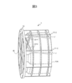
- FIG. 3 is a perspective view of a motor case showing an embodiment of the present invention.
- FIG. 1 shows an embodiment of the present invention and is a front view of a motor case 1 of a rotating electric machine.
- the motor case 1 forms a cylindrical peripheral wall 10, and a circular flange portion 13 protruding to the outer periphery is formed at an end of the peripheral wall 10 on the left side in the drawing.
- the flange 13 is on the output side of the motor case 1, and a reduction gear (or a mechanical element such as a transmission) not shown is attached to the flange portion 13.
- a flange portion 13 is formed at one end of the peripheral wall 10 in the axial direction, and an opening end 10A is formed at the other end, and a stator, a rotor (shaft 2 and rotor), etc. are incorporated from the opening end 10A.
- linear ribs 11-1 to 11-4 parallel to the axis C1 of the shaft (rotating shaft) 2 are formed at predetermined intervals.
- the linear ribs 11-1 to 11-4 radially protrude from the outer periphery of the peripheral wall 10 around the axis C1 at a predetermined height.
- the reference numeral “11” is used by omitting “ ⁇ ” and thereafter. The same applies to the reference numerals of other components.
- annular ribs 12-1 to 12-3 are formed on the outer periphery of the peripheral wall 10 at predetermined intervals in the axial direction of the axis C1.
- the annular rib 12 is formed at a predetermined height from the outer circumference of the peripheral wall 10 on a plane orthogonal to the axis C1.
- a damping rib 20-1 is formed by intersecting two linear ribs. , 20-2 are formed.
- the damping rib 20 projects from the outer periphery of the peripheral wall 10 to a predetermined height.
- the damping rib 20-1 (first rib) is formed at an angle larger than 0° and smaller than 90° with respect to the axis C1 direction of the shaft 2, and the damping rib 20-2 (second rib) is formed.
- the angle is greater than 90° and less than 180° with respect to the axis C1 direction of the shaft 2.
- damping ribs 20-1 and 20-2 intersect at a predetermined angle to connect the linear rib 11-2, the linear rib 11-3, and the flange portion 13.
- FIG. 2 is a half sectional view of the motor case 1 of the rotary electric machine.
- a through hole 40 through which the shaft 2 is inserted is formed on the inner periphery of the motor case 1 on the flange portion 13 side.
- a planar inner peripheral surface 13A is formed on the back side of the flange portion 13 facing the inside of the peripheral wall 10.
- a cylindrical space is formed inside the peripheral wall 10 from the inner peripheral surface 13A to the opening end 10A, and the stator 4, the shaft 2, and the rotor 3 are housed therein.
- a bearing (not shown) is attached to the through hole 40 to rotatably support the shaft 2.
- the cylindrical space inside the peripheral wall 10 is formed with spaces having different inner diameters, and a space having a small inner diameter is formed from the inner peripheral surface 13A of the flange portion 13 to a predetermined distance L2 in the axial direction, and from the predetermined distance L2.
- a space having a large inner diameter is formed up to the open end 10A.
- a step portion 21 is formed at a position of a distance L2 in the direction of the axis C1 from the inner peripheral surface 13A, which is a boundary between the spaces having different inner diameters, and the end portion 4A of the stator 4 abuts.
- the step portion 21 functions as a wall surface for positioning the end portion 4A of the stator 4.
- the damping rib 20 formed on the outer periphery of the peripheral wall 10 will be described.
- the position of the outer peripheral surface 13B of the flange portion 13 connected to the outer periphery of the peripheral wall 10 on the side of the open end 10A and the inner peripheral surface 13A inside the peripheral wall 10 in the direction of the axis C1 are the same.
- the outer peripheral surface 13B of the flange portion 13 is formed as a flat surface rising from the outer periphery of the peripheral wall 10.
- the damping rib 20-1 is connected to the linear rib 11-3 (see FIG. 1) at the end on the flange 13 side, is inclined at a predetermined angle with respect to the axis C1, and has the other end at the linear rib 11-. Connect to 2.
- the position in the direction of the axis C1 where the damping rib 20-1 connects with the linear rib 11-2 is set to a predetermined distance L1 from the outer peripheral surface 13B of the flange portion 13.
- the damping rib 20-2 is connected to the linear rib 11-2 at the end on the flange portion 13 side, is inclined at a predetermined angle with respect to the axis C1, and has the other end at the linear rib 11-3( (See FIG. 1).
- the position in the direction of the axis C1 where the damping rib 20-2 connects with the linear rib 11-3 is set to a predetermined distance L1 from the outer peripheral surface 13B of the flange portion 13.
- the damping ribs 20-1 and 20-2 are connected to the linear rib 11 at the same position L1 in the direction of the axis C1.
- the distance L1 from the outer peripheral surface 13B of the flange portion 13 is set larger than the distance L2 from the inner peripheral surface 13A where the end portion 4A (step portion 21) of the stator 4 is arranged.
- the electromagnetic excitation force of the rotating electric machine is generated between the rotor 3 and the stator 4.
- the electromagnetic excitation force is transmitted to the motor case 1 via the stator 4.
- the arrangement of the damping ribs 20 is determined by focusing on the electromagnetic exciting force generated by the stator 4. That is, the outer periphery of the peripheral wall 10 is partially cut off from the flange portion 13 that connects the rotating electric machine to the speed reducer, in the section (distance L2) in the direction of the axis C1 that corresponds to the end portion 4A of the stator 4 that generates electromagnetic excitation force.
- the damping rib 20 is arranged so as to cover it.
- an X-shaped damping rib 20 that intersects two linear ribs is formed from the outer peripheral surface 13B on the outer peripheral side of the peripheral wall 10 to a distance L1, and the end portion 4A of the stator 4 inside the peripheral wall 10 is formed. Cover.
- the position of the damping rib 20 in the direction of the axis C1 is set to a distance L1 that is larger than the distance L2 from the inner peripheral surface 13A of the flange 13 to the end 4A of the stator 4.
- the outer periphery of the peripheral wall 10 whose position in the axial direction C1 coincides with the end portion 4A of the stator 4 in the radial direction is covered with the damping rib 20.
- the damping ribs 20 are intermittently arranged in the circumferential direction of the peripheral wall 10 in consideration of the mold.
- the vibration suppressing rib 20 connected to the flange portion 13 is formed between the linear ribs 11-2 and 11-3, and the linear ribs 11-1 and 11-2 are formed.
- An example in which the damping rib 20 is not formed is shown, but the present invention is not limited to this.
- the motor case 1 is manufactured by cutting, it is possible to form the damping ribs 20 on the entire circumference between the adjacent linear ribs 11.
- FIG. 3 is a perspective view of the motor case 1 of the rotating electric machine.
- the linear rib 11 of the motor case 1 is deformed by the electromagnetic excitation force f.
- the flange portion 13 of the motor case 1 is coupled to the speed reducer that transmits the output of the rotating electric machine and the rotor (the rotor 3 and the shaft 2) generates torque, the electromagnetic excitation force f is generated.
- the electromagnetic excitation force f acts so as to twist the linear rib 11 downward in the drawing on the side of the opening end 10A, as shown by the arrow in the figure.
- the vibration suppressing rib 20-1 receives the force in the compression direction and supports the downward bending of the linear rib 11-2 at the end on the flange portion 13 side, so that the linear rib 11-2 is deformed. Suppress.
- the vibration suppressing rib 20-2 supports the downward bending of the linear rib 11-3 by the force in the pulling direction at the end of the flange portion 13 side so that the linear rib 11-3 is not deformed. Suppress.
- the motor It is possible to promote the weight reduction while improving the torsional rigidity of the case 1.
- the vibration damping rib 20 is formed by intersecting the two ribs connecting the flange portion 13 and the linear ribs 11-2 and 11-3, and the position where the vibration damping rib 20 is formed. Is the outer circumference of the peripheral wall 10 that covers the flange portion 13 to the end portion 4A of the stator 4.
- the linear ribs 11 are supported by a plurality of ribs between the end 4A of the stator 4 and the circumferential wall 10 on the radial extension of the shaft 2 to the outer peripheral surface 13B of the flange 13.
- the swing rib 20 is formed.
- the position of the damping rib 20 is described with reference to the axis C1 of the shaft 2, but the axis of the peripheral wall 10 may be used as a reference.
- the inside of the peripheral wall 10 may be a space having a single inner diameter, and a spacer or the like may be inserted on the inner peripheral surface 13A side.
- peripheral wall 10 has a cylindrical shape
- a cylindrical shape capable of accommodating the stator 4 and the rotor (the shaft 2 and the rotor 3) may be used.
- the linear rib 11 parallel to the direction of the axis C1 is formed on the outer periphery of the peripheral wall 10
- the outer periphery of the peripheral wall 10 may not have a rib in the direction of the axis C1.
- a rib inclined with respect to the axis C1 may be provided on the outer periphery of the peripheral wall 10.
- the motor case 1 of the above-described embodiment includes the stator (4), the rotor (3) facing the inner circumference of the stator (4), and the rotating shaft (2) coupled to the rotor (3).
- the stator (4) and the rotating shaft (2) are housed, and the motor case is formed in a tubular shape and houses the stator (4) and the rotating shaft (2) therein.
- a control formed by a plurality of ribs is formed between a position intersecting the outer circumference of the peripheral wall (10) and the flange portion (13). And a swing rib (20).
- vibration damping rib 20 in which a plurality of ribs (20-1, 20-2) are combined on the outer periphery of the peripheral wall 10 of the motor case 1 in a section corresponding to the end portion 4A of the flange 4 from the flange portion 13, It is possible to promote the weight reduction while improving the torsional rigidity of the motor case 1.
- the damping rib (20) intersects a plurality of linear ribs (20-1, 20-2).
- the vibration suppression rib 20-1 supports the force in the compression direction
- the vibration suppression rib 20-2 supports the force in the pulling direction and suppresses it.
- the vibration ribs 20 suppress torsional vibrations, and can improve the torsional rigidity of the peripheral wall 10 from the outer circumference in the radial direction of the end portion 4A of the stator 4 to the flange portion 13.
- the weight of the plurality of linear ribs (20-1, 20-2) is light, it is possible to suppress an excessive increase in the weight of the motor case 1.
- a linear rib parallel to the axial direction of the rotating shaft (2) is formed on the outer periphery of the peripheral wall (10), and the damping rib (20) includes the linear rib and the flange portion (13). Connecting.
- the vibration suppressing rib 20-1 receives the force in the compression direction and the linear rib 11-2 is twisted downward so that the end portion on the side of the flange portion 13 side.
- the vibration suppressing rib 20-2 supports the downward bending of the linear rib 11-3 by the force in the pulling direction at the end of the flange portion 13 side so that the linear rib 11-3 is not deformed. Suppress.
- the vibration damping rib 20 can suppress torsional vibration and improve the torsional rigidity of the peripheral wall 10 from the radial outer circumference of the end portion 4A of the stator 4 to the flange portion 13.
- the plurality of ribs include a first rib and a second rib, and the first rib is formed at an angle larger than 0° and smaller than 90° with respect to the axial direction of the rotating shaft (2).
- the second rib is formed at an angle larger than 90° and smaller than 180° with respect to the axial direction of the rotating shaft (2).
- the motor case is formed. It is possible to promote the weight reduction while improving the torsional rigidity of 1.
- the damping rib 20-1 By intersecting the damping rib 20-1 and the damping rib 20-2, when the damping rib 20-1 receives a compressive load and the damping rib 20-2 receives a tensile load, the damping rib 20-1 By dispersing the vibration damping rib 20-2 from the position where it intersects with the rib 20-1, deformation of the vibration damping rib 20-2 due to tension can be reduced, and torsional vibration can be reduced.
- the present invention is not limited to the above-described embodiments, but includes various modifications.
- the above-described embodiments are described in detail in order to explain the present invention in an easy-to-understand manner, and are not necessarily limited to those having all the configurations described.
- a part of the configuration of a certain embodiment can be replaced with the configuration of another embodiment, and the configuration of another embodiment can be added to the configuration of a certain embodiment.
- any addition, deletion, or replacement of other configurations can be applied alone or in combination.
Landscapes
- Engineering & Computer Science (AREA)
- Power Engineering (AREA)
- Motor Or Generator Frames (AREA)
Abstract
Description
以上のように、上記実施例のモーターケース1は、ステータ(4)と、前記ステータ(4)の内周に対向するロータ(3)と、前記ロータ(3)に結合される回転軸(2)と、前記ステータ(4)及び回転軸(2)を収容するモーターケースであって、前記モーターケースは、筒状に形成されて内部に前記ステータ(4)及び回転軸(2)を収容する空間を有する周壁(10)と、前記周壁(10)の一端に形成されて外部に結合されるフランジ部(13)と、前記周壁(10)の外周に形成されて、前記ステータ(4)の端部から前記回転軸(2)の半径方向の延長上で、前記周壁(10)の外周と交差する位置から、前記フランジ部(13)までの間に形成され複数のリブで構成される制振リブ(20)と、を有する。
2 シャフト
3 ロータ
4 ステータ
4A 端部
10 周壁
11-1~11-4 軸方向リブ
12-1~12-3 周方向リブ
13 フランジ部
13A 内周面
20-1、20-2 制振リブ
21 段部
Claims (4)
- ステータと、前記ステータの内周と対向するロータと、前記ロータに結合される回転軸と、を収容するモーターケースであって、
前記モーターケースは、
筒状に形成されて内部に前記ステータ及び回転軸を収容する空間を有する周壁と、
前記周壁の一端に形成されて外部に結合されるフランジ部と、
前記周壁の外周に形成されて、前記ステータの端部から前記回転軸の径方向の延長上で、前記周壁の外周と交差する位置から、前記フランジ部までの間に形成され複数のリブで構成される制振リブと、
を有することを特徴とするモーターケース。 - 請求項1に記載のモーターケースであって、
前記制振リブは、
複数の直線状のリブを交差させることを特徴とするモーターケース。 - 請求項2に記載のモーターケースであって、
前記周壁の外周には、前記回転軸の軸方向と平行な直線リブが形成され、
前記制振リブは、
前記直線リブと前記フランジ部を接続することを特徴とするモーターケース。 - 請求項2に記載のモーターケースであって、
前記複数のリブは、第1のリブと第2のリブを含み、前記第1のリブは、前記回転軸の軸方向に対して0゜より大きく90゜より小さい角度で形成され、前記第2のリブは、前記回転軸の軸方向に対して90゜より大きく180゜より小さい角度で形成されることを特徴とするモーターケース。
Priority Applications (4)
| Application Number | Priority Date | Filing Date | Title |
|---|---|---|---|
| US17/293,144 US12003165B2 (en) | 2019-01-08 | 2019-12-13 | Motor case |
| CN201980078511.6A CN113228473B (zh) | 2019-01-08 | 2019-12-13 | 马达壳体 |
| JP2020565652A JP7153745B2 (ja) | 2019-01-08 | 2019-12-13 | モーターケース |
| EP19908848.5A EP3859948B1 (en) | 2019-01-08 | 2019-12-13 | Motor case |
Applications Claiming Priority (2)
| Application Number | Priority Date | Filing Date | Title |
|---|---|---|---|
| JP2019001346 | 2019-01-08 | ||
| JP2019-001346 | 2019-01-08 |
Publications (1)
| Publication Number | Publication Date |
|---|---|
| WO2020145034A1 true WO2020145034A1 (ja) | 2020-07-16 |
Family
ID=71520512
Family Applications (1)
| Application Number | Title | Priority Date | Filing Date |
|---|---|---|---|
| PCT/JP2019/048884 Ceased WO2020145034A1 (ja) | 2019-01-08 | 2019-12-13 | モーターケース |
Country Status (5)
| Country | Link |
|---|---|
| US (1) | US12003165B2 (ja) |
| EP (1) | EP3859948B1 (ja) |
| JP (1) | JP7153745B2 (ja) |
| CN (1) | CN113228473B (ja) |
| WO (1) | WO2020145034A1 (ja) |
Cited By (2)
| Publication number | Priority date | Publication date | Assignee | Title |
|---|---|---|---|---|
| JP2022104053A (ja) * | 2020-12-28 | 2022-07-08 | 日立Astemo株式会社 | 液冷式電動モータ |
| WO2024127884A1 (ja) * | 2022-12-14 | 2024-06-20 | 株式会社アイシン | 筐体 |
Families Citing this family (2)
| Publication number | Priority date | Publication date | Assignee | Title |
|---|---|---|---|---|
| WO2020145034A1 (ja) * | 2019-01-08 | 2020-07-16 | 日立オートモティブシステムズ株式会社 | モーターケース |
| JP7768711B2 (ja) * | 2021-09-29 | 2025-11-12 | ニデック株式会社 | 電動パワーユニット |
Citations (4)
| Publication number | Priority date | Publication date | Assignee | Title |
|---|---|---|---|---|
| JP2000060059A (ja) * | 1998-08-12 | 2000-02-25 | Hitachi Ltd | 回転電機 |
| JP2009232658A (ja) * | 2008-03-25 | 2009-10-08 | Asmo Co Ltd | 回転電機 |
| JP2009232601A (ja) | 2008-03-24 | 2009-10-08 | Mitsuba Corp | モータ |
| JP2017070120A (ja) * | 2015-09-30 | 2017-04-06 | アルプス電気株式会社 | リブ構造及び位置検出装置 |
Family Cites Families (9)
| Publication number | Priority date | Publication date | Assignee | Title |
|---|---|---|---|---|
| CA2087763C (en) * | 1992-02-11 | 2002-07-02 | Jimmy Cochimin | Stator frame for dynamoelectric machine and method for making same |
| US6963153B1 (en) * | 2004-06-01 | 2005-11-08 | Wei-Chung Su | Housing of motor |
| WO2006108550A1 (de) * | 2005-04-12 | 2006-10-19 | Sew-Eurodrive Gmbh & Co. Kg | Elektromotor |
| JP2008072881A (ja) * | 2006-09-15 | 2008-03-27 | Toyota Motor Corp | モータ |
| TW201319394A (zh) * | 2011-11-07 | 2013-05-16 | Assoma Inc | 永磁罐裝泵之防蝕外殼結構改良 |
| DE102012023050A1 (de) * | 2012-11-26 | 2014-05-28 | Volkswagen Aktiengesellschaft | Elektrische Maschine und Verfahren zur Herstellung einer elektrischen Maschine |
| US20160329760A1 (en) * | 2015-05-07 | 2016-11-10 | Nidec Motor Corporation | Stator and motor shell interconnection |
| JP6364444B2 (ja) | 2016-06-14 | 2018-07-25 | 本田技研工業株式会社 | 回転電機のステータ |
| WO2020145034A1 (ja) * | 2019-01-08 | 2020-07-16 | 日立オートモティブシステムズ株式会社 | モーターケース |
-
2019
- 2019-12-13 WO PCT/JP2019/048884 patent/WO2020145034A1/ja not_active Ceased
- 2019-12-13 JP JP2020565652A patent/JP7153745B2/ja active Active
- 2019-12-13 CN CN201980078511.6A patent/CN113228473B/zh active Active
- 2019-12-13 US US17/293,144 patent/US12003165B2/en active Active
- 2019-12-13 EP EP19908848.5A patent/EP3859948B1/en active Active
Patent Citations (4)
| Publication number | Priority date | Publication date | Assignee | Title |
|---|---|---|---|---|
| JP2000060059A (ja) * | 1998-08-12 | 2000-02-25 | Hitachi Ltd | 回転電機 |
| JP2009232601A (ja) | 2008-03-24 | 2009-10-08 | Mitsuba Corp | モータ |
| JP2009232658A (ja) * | 2008-03-25 | 2009-10-08 | Asmo Co Ltd | 回転電機 |
| JP2017070120A (ja) * | 2015-09-30 | 2017-04-06 | アルプス電気株式会社 | リブ構造及び位置検出装置 |
Non-Patent Citations (1)
| Title |
|---|
| See also references of EP3859948A4 |
Cited By (3)
| Publication number | Priority date | Publication date | Assignee | Title |
|---|---|---|---|---|
| JP2022104053A (ja) * | 2020-12-28 | 2022-07-08 | 日立Astemo株式会社 | 液冷式電動モータ |
| JP7482023B2 (ja) | 2020-12-28 | 2024-05-13 | 日立Astemo株式会社 | 液冷式電動モータ |
| WO2024127884A1 (ja) * | 2022-12-14 | 2024-06-20 | 株式会社アイシン | 筐体 |
Also Published As
| Publication number | Publication date |
|---|---|
| US20220352786A1 (en) | 2022-11-03 |
| JPWO2020145034A1 (ja) | 2021-09-27 |
| EP3859948B1 (en) | 2026-02-04 |
| US12003165B2 (en) | 2024-06-04 |
| JP7153745B2 (ja) | 2022-10-14 |
| EP3859948A1 (en) | 2021-08-04 |
| CN113228473A (zh) | 2021-08-06 |
| EP3859948A4 (en) | 2022-06-01 |
| CN113228473B (zh) | 2024-12-27 |
Similar Documents
| Publication | Publication Date | Title |
|---|---|---|
| WO2020145034A1 (ja) | モーターケース | |
| JP5081005B2 (ja) | ブラシレスモータ及びその製造方法 | |
| JP5488614B2 (ja) | ステータコアの固定構造およびそれを備えた回転電機 | |
| JP2010019360A (ja) | 自動変速機における筒状部材の支持構造 | |
| WO2012140771A1 (ja) | 動力伝達装置 | |
| JP4238093B2 (ja) | モータの支持構造 | |
| JP6477313B2 (ja) | 電動機 | |
| EP1818241A2 (en) | Motor for electric power steering apparatus and method of manufacturing a dynamic damper | |
| JP7275433B2 (ja) | モータ付きギアシステム及び車載用ブレーキシステム | |
| JP2018068011A (ja) | 複軸並列電動機 | |
| JP2006304558A (ja) | モータ組込みハイポサイクロイド減速機 | |
| JP2008022616A (ja) | アクチュエータ装置 | |
| JP2023144285A (ja) | 動力伝達装置 | |
| JP2007300764A (ja) | 電動パワーステアリング用モータ | |
| JP2022154273A (ja) | モータ | |
| JP2008005576A (ja) | ギヤドモータ及びロボット用ギヤドモータ | |
| JP6369105B2 (ja) | モータのロータ構造 | |
| JP2020083294A (ja) | モーター取付エンジンのダンパー | |
| JP2007325348A (ja) | 回転電機 | |
| JP2022133806A (ja) | ステータコア支持装置 | |
| JP7673463B2 (ja) | モータ | |
| JP5460363B2 (ja) | ブラシレスモータ | |
| JP2017044265A (ja) | 回転軸ケース | |
| JP2007210386A (ja) | 電動パワーステアリング用モータ | |
| JP2023183103A (ja) | モータユニット |
Legal Events
| Date | Code | Title | Description |
|---|---|---|---|
| 121 | Ep: the epo has been informed by wipo that ep was designated in this application |
Ref document number: 19908848 Country of ref document: EP Kind code of ref document: A1 |
|
| ENP | Entry into the national phase |
Ref document number: 2020565652 Country of ref document: JP Kind code of ref document: A |
|
| ENP | Entry into the national phase |
Ref document number: 2019908848 Country of ref document: EP Effective date: 20210428 |
|
| NENP | Non-entry into the national phase |
Ref country code: DE |
|
| WWG | Wipo information: grant in national office |
Ref document number: 201980078511.6 Country of ref document: CN |
|
| WWG | Wipo information: grant in national office |
Ref document number: 2019908848 Country of ref document: EP |