WO2020145153A1 - シリンダヘッド - Google Patents
シリンダヘッド Download PDFInfo
- Publication number
- WO2020145153A1 WO2020145153A1 PCT/JP2019/050940 JP2019050940W WO2020145153A1 WO 2020145153 A1 WO2020145153 A1 WO 2020145153A1 JP 2019050940 W JP2019050940 W JP 2019050940W WO 2020145153 A1 WO2020145153 A1 WO 2020145153A1
- Authority
- WO
- WIPO (PCT)
- Prior art keywords
- cylinder head
- heat insulating
- insulating member
- intake port
- seal member
- Prior art date
- Legal status (The legal status is an assumption and is not a legal conclusion. Google has not performed a legal analysis and makes no representation as to the accuracy of the status listed.)
- Ceased
Links
Images







Classifications
-
- F—MECHANICAL ENGINEERING; LIGHTING; HEATING; WEAPONS; BLASTING
- F02—COMBUSTION ENGINES; HOT-GAS OR COMBUSTION-PRODUCT ENGINE PLANTS
- F02F—CYLINDERS, PISTONS OR CASINGS, FOR COMBUSTION ENGINES; ARRANGEMENTS OF SEALINGS IN COMBUSTION ENGINES
- F02F1/00—Cylinders; Cylinder heads
- F02F1/24—Cylinder heads
- F02F1/42—Shape or arrangement of intake or exhaust channels in cylinder heads
- F02F1/4235—Shape or arrangement of intake or exhaust channels in cylinder heads of intake channels
-
- F—MECHANICAL ENGINEERING; LIGHTING; HEATING; WEAPONS; BLASTING
- F02—COMBUSTION ENGINES; HOT-GAS OR COMBUSTION-PRODUCT ENGINE PLANTS
- F02F—CYLINDERS, PISTONS OR CASINGS, FOR COMBUSTION ENGINES; ARRANGEMENTS OF SEALINGS IN COMBUSTION ENGINES
- F02F1/00—Cylinders; Cylinder heads
- F02F1/24—Cylinder heads
- F02F1/42—Shape or arrangement of intake or exhaust channels in cylinder heads
- F02F1/4235—Shape or arrangement of intake or exhaust channels in cylinder heads of intake channels
- F02F1/425—Shape or arrangement of intake or exhaust channels in cylinder heads of intake channels with a separate deviation element inside the channel
-
- F—MECHANICAL ENGINEERING; LIGHTING; HEATING; WEAPONS; BLASTING
- F02—COMBUSTION ENGINES; HOT-GAS OR COMBUSTION-PRODUCT ENGINE PLANTS
- F02F—CYLINDERS, PISTONS OR CASINGS, FOR COMBUSTION ENGINES; ARRANGEMENTS OF SEALINGS IN COMBUSTION ENGINES
- F02F1/00—Cylinders; Cylinder heads
- F02F1/24—Cylinder heads
- F02F1/42—Shape or arrangement of intake or exhaust channels in cylinder heads
- F02F1/4235—Shape or arrangement of intake or exhaust channels in cylinder heads of intake channels
- F02F1/4257—Shape or arrangement of intake or exhaust channels in cylinder heads of intake channels with an intake liner
-
- F—MECHANICAL ENGINEERING; LIGHTING; HEATING; WEAPONS; BLASTING
- F02—COMBUSTION ENGINES; HOT-GAS OR COMBUSTION-PRODUCT ENGINE PLANTS
- F02F—CYLINDERS, PISTONS OR CASINGS, FOR COMBUSTION ENGINES; ARRANGEMENTS OF SEALINGS IN COMBUSTION ENGINES
- F02F11/00—Arrangements of sealings in combustion engines
- F02F11/002—Arrangements of sealings in combustion engines involving cylinder heads
-
- Y—GENERAL TAGGING OF NEW TECHNOLOGICAL DEVELOPMENTS; GENERAL TAGGING OF CROSS-SECTIONAL TECHNOLOGIES SPANNING OVER SEVERAL SECTIONS OF THE IPC; TECHNICAL SUBJECTS COVERED BY FORMER USPC CROSS-REFERENCE ART COLLECTIONS [XRACs] AND DIGESTS
- Y02—TECHNOLOGIES OR APPLICATIONS FOR MITIGATION OR ADAPTATION AGAINST CLIMATE CHANGE
- Y02T—CLIMATE CHANGE MITIGATION TECHNOLOGIES RELATED TO TRANSPORTATION
- Y02T10/00—Road transport of goods or passengers
- Y02T10/10—Internal combustion engine [ICE] based vehicles
- Y02T10/12—Improving ICE efficiencies
Definitions
- the present invention relates to an engine cylinder head.
- Patent Document 1 discloses an engine intake passage structure in which a resin heat insulating member is arranged on the inner surface of an intake port to suppress a rise in intake air temperature.
- the heat insulating member is used for the intake air. It is important not to block the flow. This is because even if the rise in intake air temperature can be suppressed by the heat insulating member, the merit of disposing the heat insulating member is reduced if the intake resistance is increased.
- Patent Document 1 As a method of disposing a heat insulating member made of resin on the inner surface of the intake port, injection molding can be mentioned as in Patent Document 1 above. That is, this is a method in which a mold is inserted and fixed in a portion of the cylinder head that is molded by casting and serves as an intake port, and the space between the inner surface of this portion and the outer surface of the mold is filled with resin. When this method is adopted, it is important to secure a sealing surface so that the resin does not leak outside the above space. However, since the cylinder head itself is a casting, the dimensional accuracy is rough, and it is difficult to secure a sealing surface. On the other hand, it is possible to machine the inner surface of the part that will be the intake port to secure the sealing surface, but inserting a tool into the narrow space on the combustion chamber side to machine the machining time and accuracy. However, it is difficult to consider the processing cost.
- the cylinder head of the present invention has been devised in view of such a problem, and one of its purposes is to improve the positioning accuracy of the resin heat insulating member arranged in the intake port and avoid an increase in intake resistance. ..
- the present invention is not limited to this purpose, and it is also for the other purpose of the present invention to provide operational effects that are obtained by the respective configurations shown in the modes for carrying out the invention to be described later and that cannot be obtained by the conventional technology. is there.
- the cylinder head disclosed herein includes a cylinder head body in which an intake port communicating with the combustion chamber of the engine is formed, and a resinous and annular heat insulating member disposed inside the intake port.
- a step portion is formed on the downstream side of the heat insulating member in the flow direction of the intake air so that the size of the cross section orthogonal to the flow direction is smaller than the upstream side of the flow direction,
- An annular seal member that seals between the heat insulating member and the step portion is arranged between the heat insulating member and the step portion.
- the seal member is preferably an elastic body.
- the seal member and the heat insulating member are made of different materials.
- an insertion hole, through which the valve guide is inserted, is formed in the cylinder head body so as to communicate with the intake port. In this case, it is preferable that the step portion is located upstream of the opening of the insertion hole in the flow direction.
- the seal member is provided with a wall portion along the inner surface of the intake port in a state where the seal member is fitted in the step portion.
- the intake port is formed in a bifurcated shape that communicates with the combustion chamber via two intake valve holes, and the step portion is formed at a bifurcating point of the bifurcation of the intake port or at a bifurcating point. It is preferably located on the downstream side in the flow direction.
- the seal member includes two annular portions that fit into the bifurcated step portion and a connecting portion that connects the two annular portions.
- the connecting portion is thinner than each of the annular portions.
- the disclosed cylinder head it is possible to improve the positioning accuracy of the heat insulating member arranged in the intake port. Therefore, it is possible to avoid both the increase in intake resistance due to the resin flowing out from the heat insulating member and the increase in intake resistance due to a part of the tip of the heat insulating member rising in the intake port. It can contribute to improvement. Further, since the temperature rise of the intake air can be suppressed by the heat insulating member, the reduction of the intake air amount and the occurrence of knocking can be suppressed, and the engine performance can be improved.
- FIG. 3 is a schematic front view of the intake side portion of the cylinder head according to the embodiment as viewed from the front side of the engine.
- FIG. 2 is a schematic side view of the cylinder head of FIG. 1 viewed from the intake side (a view in the direction of arrow A in FIG. 1 ).
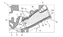
- FIG. 3 is a cross-sectional view (cross-sectional view taken along the line BB of FIG. 2) showing the configuration around the intake port of the cylinder head of FIG. 1.
- FIG. 4 is a cross-sectional view showing only a cylinder head main body, excluding a heat insulating member from the cross-sectional view of FIG. 3.
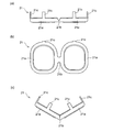
- FIG. 6 is an enlarged side view showing a state when the seal member shown in FIG. 5C is inserted into an intake port.
- FIG. 5 is a cross-sectional view showing a state in which a seal member is fitted in the step portion of the intake port shown in FIG. 4.
- FIG. 4 is a perspective view showing an example of a slide mold for molding the intake port shown in FIG. 3, (a) showing a completely assembled state, and (b) showing a state in which one side mold is displaced.
- FIG. 9 is a cross-sectional view showing a state in which the slide die shown in FIG. 8A is inserted (a cross-sectional view corresponding to the cross-sectional view taken along the line CC in FIG. 1 ).
- FIG. 1 is a schematic front view of an intake side portion of a cylinder head 1 according to the present embodiment as viewed from the front side of the engine
- FIG. 2 is a side view of the cylinder head 1 (a view in the direction of arrow A in FIG. 1). ).
- the cylinder head 1 is a component that constitutes, for example, an engine mounted on a vehicle.
- This embodiment exemplifies a cylinder head 1 of an engine in which four cylinders are arranged side by side in a row, and one cylinder is provided with two intake valves and two exhaust valves.
- the engine of the present embodiment includes a cylinder injection valve (not shown) that injects fuel into the combustion chamber 2 (see FIG. 3) and a port injection valve (not shown) that injects fuel into the intake port 3. Equipped.
- FIG. 3 is a cross-sectional view (a cross-sectional view taken along the line BB of FIG. 2) showing the configuration around the intake port 3.
- the cylinder head 1 includes a cylinder head body 10 molded by casting using, for example, aluminum or an aluminum alloy, and a heat insulating member 20 and a sealing member 21 (see FIG. 3) described later.
- a cylinder head body 10 molded by casting using, for example, aluminum or an aluminum alloy, and a heat insulating member 20 and a sealing member 21 (see FIG. 3) described later.
- an intake port 3 a port injection valve mounting hole 5 and an in-cylinder injection valve mounting hole 6 are formed for each cylinder.
- the intake port 3 and the mounting holes 5 and 6 open in the wall portion 1a of the cylinder head 1 on the intake side.
- a pedestal portion 8 to which a delivery pipe connected to the in-cylinder injection valve is fixed, and an injection port 9 for supplying a molten resin to be a resin portion 22 (see FIG. 3) described later are provided in the wall portion 1a. Are formed.
- the cylinder head main body 10 constitutes the main body of the cylinder head 1, and as shown in FIGS. 3 and 4, has a combustion chamber 2, mounting holes 5, 6 and the like, and constitutes the intake port 3. It has a part 11 (a part which becomes the intake port 3). 4 is a sectional view showing only the cylinder head main body 10 from which the heat insulating member 20 and the seal member 21 are removed from the sectional view of FIG.
- the main body 11 (intake port 3) of the present embodiment is formed in a bifurcated shape that communicates with the combustion chamber 2 via two intake valve holes 4 (see FIG. 6). 3 and 4, the wall portion that divides the main body portion 11 into two forks is not shown.
- an insertion hole 7 into which a valve guide (not shown) is inserted and a port injection valve mounting hole 5 are both formed so as to communicate with the body portion 11. Further, the main body portion 11 is provided with an expanded portion 16 which is formed so as to spread to the side where the port injection valve is attached (upper side in FIG. 4), an opening 5a of the attachment hole 5 and an opening 7a of the insertion hole 7. There is.
- the heat insulating member 20 is an annular member that is arranged inside the intake port 3 (along the inner surface of the main body 11) and that suppresses the heat of the cylinder head main body 10 from being transferred to the intake air. ..
- the heat insulating member 20 is made of a resin having a lower thermal conductivity than the material of the cylinder head body 10, and more preferably a resin having a high heat resistance. Note that in FIG. 3, the heat insulating member 20 is shown with dots for easy understanding.
- the heat insulating member 20 is a portion that is provided on the upstream side in the intake air flow direction (hereinafter, simply referred to as “upstream side”) and covers the inner surface of the main body 11 extensively.
- the seal member 21 is an annular member that is provided continuously to the heat insulating member 20 on the downstream side (hereinafter, simply referred to as “downstream side”) of the intake flow with respect to the heat insulating member 20.
- downstream side the term “continuous” as used herein is not limited to a completely integrated state (a state in which there is a continuous continuation), but it is also possible that the seal member 21 and the heat insulating member 20 are fixed (as if they were integrated). It also includes the condition that can be seen in (the condition where bubbles are attached to the fixed surface).
- the materials of the heat insulating member 20 and the seal member 21 may be the same or different from each other.
- the case where the heat insulating member 20 and the seal member 21 are made of different materials is illustrated.
- the material of the sealing member 21 is a material having higher flexibility than the heat insulating member 20.
- the seal member 21 is a non-metallic elastic body (for example, resin or rubber) is illustrated.
- the heat insulating member 20 is arranged in the entire length of the main body portion 11 except for the portion on the combustion chamber 2 side (downstream portion).
- the main body 11 has a portion where the heat insulating member 20 is not arranged and a portion where the heat insulating member 20 is arranged.
- the former portion will be referred to as the exposed portion 12, and the latter portion will be referred to as the covering portion 13.
- the exposed portion 12 is a portion where the material surface of the cylinder head body 10 directly contacts (exposes) the intake air
- the covering portion 13 is covered with the heat insulating member 20 and the material surface of the cylinder head body 10. Is the part that does not directly contact the intake air.
- the heat insulating member 20 constitutes the inner surface of the intake port 3 together with the exposed portion 12.
- the exposed part 12 is located on the combustion side 2 side of the main body part 11, and the covering part 13 is located on the upstream side of the exposed part 12.
- a cross section (hereinafter, simply referred to as “cross section”) of the covering portion 13 that is orthogonal to the intake air flow direction is formed larger than the exposed portion 12. Therefore, at the boundary between the exposed portion 12 and the covering portion 13, a step portion 14 having a varying cross-sectional size is provided.
- the step portion 14 is formed downstream of the heat insulating member 20 in the intake port 3 so that the cross-sectional size of the intake port 3 is smaller than that of the upstream portion.
- the portion from the opening 11a formed in the wall portion 1a of the cylinder head body 10 to the step portion 14 is linearly formed.
- An intake manifold (not shown) is connected to the opening 11a of the main body 11.
- the step portion 14 of the present embodiment is located at a bifurcation point 15 (see FIGS. 4 and 6) of the main body portion 11 (intake port 3) or on the downstream side of the bifurcation point 15. Further, the step portion 14 is located on the upstream side of the opening 7a of the insertion hole 7 for inserting the valve guide. That is, two step portions 14 are provided in one body portion 11, and each step portion 14 is provided separately from the combustion chamber 2.
- the end portion (upstream end in the intake air flow direction) of the body portion 11 on the wall portion 1a side is narrowed, and the heat insulating member 20 is not arranged in this portion. An exposed portion 12' is provided.
- the seal member 21 is located between the heat insulating member 20 and the step portion 14 and has a function of sealing the space therebetween (that is, closely contacting and sealing both the heat insulating member 20 and the step portion 14).
- the seal member 21 of the present embodiment has two annular portions 21a that fit into the bifurcated step portion 14 and a connecting portion 21b that connects the two annular portions 21a.
- FIGS. 5A and 5B are a plan view and a front view showing the seal member 21 having the annular portion 21a taken out from the cylinder head body 10.
- the seal member 21 of the present embodiment has two annular portions 21a connected by one connecting portion 21b, and can conform to a spectacle shape.
- Each of the annular portions 21a is an annular portion that fits in the step portion 14, and corresponds to the edge (so-called rim) of the lens when compared to eyeglasses.
- the annular portion 21a has an outer shape that matches the cross section of the step portion 14 and has a substantially uniform thickness in the circumferential direction.
- the two annular portions 21a are formed in a shape that is a mirror surface, and are adjacent to each other with a gap therebetween.
- the connecting portion 21b is a portion that connects the closest portions of the two annular portions 21a, and corresponds to a bridge when compared to eyeglasses.
- the connecting portion 21b is thinner than each annular portion 21a, and as shown in FIG. 5(c), the two annular portions 21a are easily bent in the directions toward each other. It should be noted that the connecting portion 21b may be provided with a notch for assisting bending so that the connecting portion 21b can be bent more easily.
- the seal member 21 of the present embodiment is provided with wall portions 21c extending in the same direction from two locations of each annular portion 21a.
- the wall portion 21c is a portion along the inner surface of the covering portion 13 of the intake port 3 in a state where the seal member 21 is fitted in the step portion 14 as shown in FIG. 3, and as shown in FIG. When the seal member 21 is bent, it extends inward.
- the wall portion 21c has both a function of maintaining the posture when the seal member 21 is installed in the main body portion 11 and a function of promoting integration with the molten resin when the molten resin to be the heat insulating member 20 is injected. ..
- the seal member 21 in which the two wall portions 21c are provided in the respective annular portions 21a so as to be offset from each other by 90 degrees is illustrated, but the number and arrangement of the wall portions 21c are not limited to this.
- the thickness of the heat insulating member 20 and the thickness of the sealing member 21 are set according to the difference in the size of the cross section of the covering portion 13 with respect to the exposed portion 12 (the height difference of the step portion 14 ). This is because if the inner surface of the exposed portion 12 and the inner surfaces of the heat insulating member 20 and the seal member 21 are smoothly connected, an increase in intake resistance can be avoided. That is, if the height difference of the step portion 14 and the thickness of the heat insulating member 20 and the thickness of the seal member 21 are set to be substantially the same, the seal member 21 is fitted in the step portion 14 and the heat insulating member 20 is placed in the covering portion 13. This is because the heat insulating member 20, the seal member 21, and the exposed portion 12 can form a flush inner surface in the arranged state.
- the seal member 21 is inserted from the opening 11a of the main body 11 formed in the wall 1a. Since the opening 11a of the main body 11 is smaller than the cross section in the middle of the main body 11, the seal member 21 is inserted in a bent state as shown in FIG. 5C. Then, as shown in FIG. 7, the seal member 21 is fitted into the step portion 14.
- the mold 30 is inserted through the opening 11a, and the tip portion of the mold 30 is brought into close contact with the seal member 21.
- FIGS. An example of the mold 30 is shown in FIGS.
- the mold 30 according to the present embodiment has an outer shape smaller than the inner shape of the main body 11, and is a combination of a plurality of parts divided along the direction of insertion into the main body 11 (the intake air circulation direction). It is a slide type.
- the mold 30 includes an upper mold 31 arranged on the upper part including the expansion part 16 of the main body 11, a lower mold 32 arranged below the upper mold 31, and an upper mold 31 and a lower mold 32.
- the central mold 33 is disposed between the central mold 33, the lateral molds 34 arranged on both sides of at least the central mold 33, and the valve mold 35 inserted into the mounting hole 5.
- the side mold 34 shown in FIGS. 8(a) and 8(b) is formed in such a shape as to contact the entire sides of the upper mold 31 and the lower mold 32. As shown in FIG. 8B, the side mold 34 is formed slidably with respect to the respective molds 31 to 33. Further, the central mold 33 is formed slidably with respect to both the upper mold 31 and the lower mold 32. Further, the valve die 35 is formed in a shape that fits into the upper die 31, and has a function of holding the upper die 31.
- the insertion order of the slide mold 30 will be described.
- the upper mold 31 is inserted through the opening 11a and accommodated in the expanded portion 16, and in this state, the valve mold 35 is inserted through the mounting hole 5 and fitted into the upper mold 31. ..
- the lower die 32 is inserted through the opening 11a, and the central die 33 is inserted while sliding the upper die 31 and the lower die 32, thereby assembling the three dies 31 to 33 inside the main body 11.
- the two side molds 34 are inserted while being slid with respect to the three molds 31 to 33, whereby the slide mold 30 is brought into the state shown in FIG.
- the tip portion of the slide die 30 is brought into close contact with the member 21 ′ serving as the annular portion 21.
- the molten resin to be the heat insulating member 20 is supplied to the inside of the main body 11 in which the slide mold 30 is arranged.
- the injection resin (not shown) is connected to each injection port 9 to pour the molten resin.
- the molten resin spreads into the space formed between the inner surface of the main body 11 and the outer surface of the slide die 30.
- the edge portion on the combustion chamber 2 side in the space where the molten resin spreads is sealed by the seal member 21 fitted in the step portion 14. Therefore, resin leakage to the combustion chamber 2 side is avoided.
- the slide die 30 of the present embodiment is equipped with a burr-cutting component 36 that comes into close contact with the flange surface 11b (see FIGS. 6 and 9) of the opening 11a of the main body 11. As a result, the edge portion on the side of the opening 11a in the space where the molten resin spreads is also sealed, and resin leakage is avoided.
- the seal member 21 and the molten resin are integrated, and the heat insulating member 20 and the seal member 21 are integrated.
- the slide mold 30 is pulled out in the reverse order of the insertion. That is, the two side molds 34 are slid and removed, and then the central mold 33 is removed.
- the lower mold 32 is lifted to the space created by removing the central mold 33 and then removed.
- the valve mold 35 is removed, and the upper mold 31 is lowered into the space created by removing the central mold 33 and the lower mold 32, and then removed.
- the side mold 34 and the central mold 33 first, it is possible to remove the lower mold 32 and the upper mold 31 while avoiding contact with the inner surface of the heat insulating member 20 as much as possible.
- the intake port 3 is provided with the step portion 14 whose cross-sectional size changes, and the seal member 21 that seals between the step portion 14 and the heat insulating member 20 is arranged. Therefore, the positioning accuracy of the heat insulating member 20 arranged in the intake port 3 can be improved by the seal member 21, and burrs generated during molding can be suppressed. Therefore, it is possible to avoid an increase in intake resistance due to the arrangement of the heat insulating member 20 and the seal member 21.
- the seal member 21 does not project into the intake port 3
- the heat insulating member 20 and the exposed portion 12 of the intake port 3 can be smoothly connected with the step difference reduced as much as possible. That is, since a flat inner surface can be formed, the intake resistance is increased by partially reducing the cross-sectional area in the intake port 3, and the intake resistance is caused by part of the tip of the heat insulating member 20 being raised in the intake port 3. Since it is possible to avoid any increase in the engine, it is possible to secure the air amount and contribute to the engine performance improvement.
- the heat insulating member 20 is not arranged in the portion near the combustion chamber 2 in the intake port 3 and is provided as the exposed portion 12, so that high temperature gas enters the intake port 3 due to the backflow of exhaust gas. Even so, deterioration of the heat insulating member 20 can be suppressed.
- smoothing the exposed portion 12 even if it is used for a long period of time, it is possible to suppress the accumulation of deposits due to the properties of fuel and lubricating oil, and to suppress the change in combustion performance.
- seal member 21 Since the above-mentioned seal member 21 is an elastic body, it is easy to insert it into the main body portion 11 and, moreover, it is easily crushed when the mold 30 is inserted and brought into close contact therewith, so that it closely adheres to the mold 30 and eliminates a gap. be able to. As a result, the leakage of the molten resin can be prevented, so that an increase in intake resistance due to the heat insulating member 20 can be suppressed. When the seal member 21 is made of resin, it is integrated with the molten resin, so that the intake resistance can be reduced.
- the seal member 21 and the heat insulating member 20 By using different materials for the seal member 21 and the heat insulating member 20 as in the above-described embodiment, it is possible to select materials suitable for their respective roles. For example, when the sealing member 21 is made of an elastic body, a high sealing effect can be exhibited and the positioning accuracy of the sealing member 21 can be further improved. Further, by selecting a material having a high heat insulating effect for the heat insulating member 20, it is possible to arrange the heat insulating member 20 having a high heat insulating effect while preventing leakage of the molten resin by the sealing member 21.
- the heat insulating member 20 is affected by the high temperature gas that flows back from the combustion chamber 2. It is possible to further suppress the deterioration caused by receiving.
- the above-mentioned seal member 21 is provided with the wall portion 21c, the posture of the seal member 21 fitted in the step portion 14 can be maintained, and the positional accuracy of the seal member 21 is further improved. Can be made.
- the wall portion 21c extends along the inner surface of the covering portion 13, the seal member 21 and the heat insulating member 20 are easily integrated via the wall portion 21c.
- the main body 11 described above is formed in a bifurcated shape, and the stepped portion 14 is located at the branch point 15 of the main body 11 or on the downstream side of the branch point 15. Since the cross section of the branch point 15 is close to a circular shape, a load can be applied substantially evenly when the mold 30 is inserted and the seal member 21 is crushed, and the crush amount of the seal member 21 can be made uniform. As a result, the effect of preventing leakage of the molten resin can be enhanced, so that an increase in intake resistance due to the heat insulating member 20 can be suppressed.
- the two annular portions 21a are connected to each other. That is, since the two annular portions 21a can be provided only by fitting one sealing member 21 to the two step portions 14, the positional accuracy can be further improved. In addition, since the annular portion 21a has the connection shape, it is possible to prevent the seal member 21 from being misoriented when the seal member 21 is inserted.
- the seal member 21 Since the connecting portion 21b described above is thinner than each annular portion 21a, the seal member 21 can be easily bent. Accordingly, the seal member 21 can be easily inserted into the main body portion 11 and can be easily and accurately fitted into the step portion 14, so that the positional accuracy of the annular portion 21a can be further improved.
- the configuration of the cylinder head 1 described above is an example and is not limited to the above.
- it may not be the cylinder head of an in-line four-cylinder engine, or the cylinder head of an engine equipped with both an in-cylinder injection valve and a port injection valve.
- the shape of the intake port does not have a bifurcated shape, and the seal member provided in one intake port is composed of one annular portion.
- seal member 21 is an elastic body (resin or rubber) is illustrated, but the material of the seal member 21 is not limited to the elastic body. Further, the seal member 21 and the heat insulating member 20 may be formed of the same material.
- the configuration of the intake port 3 described above is an example, and the position of the stepped portion 14 may be other than the position described above.
- the stepped portion may be provided on the upstream side of the branch point 15.
- the expansion part 16 is also unnecessary.
- the exposed portion 12 located on the combustion chamber 2 side, the covering portion 13 located upstream of the exposing portion 12 and covered with the heat insulating member 20, and the exposed portion 12 and the covering portion 13 It is sufficient that the step portion 14 located at the boundary is formed.
- the configuration of the heat insulating member 20 described above is an example, and is not limited to the above. At least the heat insulating member 20 is disposed inside the intake port 3, and may be a resin component formed in an annular shape.
- the configuration of the mold 30 described above is an example, and is not limited to the above.
- the slide mold 30 having the shape in which the side molds 34 are located on both sides of the upper mold 31 and the lower mold 32 has been exemplified, but the width of the central mold is reduced and the lateral molds are the upper molds. It may be a slide type which is located between the lower type and only on the side of the central type.
- the method of manufacturing the cylinder head 1 (for example, the order of inserting and withdrawing the slide dies) is also an example, and the method is not limited to the method described above. If the shape of the intake port is not undercut, a single mold may be used.
Landscapes
- Engineering & Computer Science (AREA)
- Chemical & Material Sciences (AREA)
- Combustion & Propulsion (AREA)
- Mechanical Engineering (AREA)
- General Engineering & Computer Science (AREA)
- Cylinder Crankcases Of Internal Combustion Engines (AREA)
Abstract
Description
(3)前記シール部材と前記断熱部材とが異なる材質であることが好ましい。
(4)前記シリンダヘッド本体には、バルブガイドが挿通される挿通孔が前記吸気ポートと連通するように形成されていることが好ましい。この場合、前記段差部は、前記挿通孔の開口よりも前記流れ方向の上流側に位置することが好ましい。
(6)前記吸気ポートは、二つの吸気バルブ孔を介して前記燃焼室と連通する二股形状に形成されており、前記段差部は、前記吸気ポートの二股に分かれる分岐点又は前記分岐点よりも前記流れ方向の下流側に位置することが好ましい。
(8)また、上記(7)の場合、前記連結部が、各々の前記環状部よりも薄肉であることが好ましい。
図1は、本実施形態に係るシリンダヘッド1の吸気側部分をエンジンのフロント側から見た模式的な正面図であり、図2はシリンダヘッド1の側面図(図1のA方向矢視図)である。シリンダヘッド1は、例えば車両に搭載されるエンジンを構成する部品である。本実施形態では、四つの気筒が一列に並設され、一つの気筒に二つの吸気弁と二つの排気弁とが設けられるエンジンのシリンダヘッド1を例示する。また、本実施形態のエンジンには、燃焼室2(図3参照)に燃料を噴射する筒内噴射弁(図示略)と、吸気ポート3に燃料を噴射するポート噴射弁(図示略)とが装備される。なお、図3は吸気ポート3の周辺の構成を示す断面図(図2のB-B矢視断面図)である。
次に、上述したシリンダヘッド本体10の本体部11に断熱部材20及びシール部材21を配置することでシリンダヘッド1を製造する方法について、図6~図10を用いて説明する。なお、図5(a)~(c)に示す形状を持つシール部材21は予め用意される。一方、断熱部材20は、シール部材21を本体部11内に配置したのち、射出成型によって形成される。
(1)上述したシリンダヘッド1では、吸気ポート3に断面の大きさが変化する段差部14が設けられ、この段差部14と断熱部材20との間をシールするシール部材21が配置されていることから、吸気ポート3内に配置する断熱部材20の位置決め精度をシール部材21によって向上させることができ、成型の際に発生するバリを抑制できる。したがって、断熱部材20及びシール部材21を配置することによる吸気抵抗の増大を回避できる。
(5)さらに、上述したシール部材21には壁部21cが設けられていることから、段差部14に嵌め込んだ状態のシール部材21の姿勢を保持でき、シール部材21の位置精度をさらに向上させることができる。また、壁部21cは被覆部13の内面に沿うため、シール部材21と断熱部材20とが壁部21cを介して一体化されやすくなる。
上述したシリンダヘッド1の構成は一例であって、上述したものに限られない。例えば、直列四気筒エンジンのシリンダヘッドでなくてもよいし、筒内噴射弁及びポート噴射弁の両方を備えたエンジンのシリンダヘッドでなくてもよい。また、1気筒に吸気弁が一つ設けられるエンジンのシリンダヘッドや、1気筒に吸気弁が二つ以上設けられるシリンダヘッドであって吸気ポート内で二股に分かれていないもの(吸気ポートの入口部からそれぞれ独立したポートで形成されたもの)であってもよい。この場合、吸気ポートの形状が二股形状とはならず、一つの吸気ポートに設けられるシール部材は、一つの環状部から構成される。
2 燃焼室
3 吸気ポート
4 吸気バルブ孔
7 挿通孔
7a 開口
10 シリンダヘッド本体
11 本体部
12 露出部
13 被覆部
14 段差部
15 分岐点
20 断熱部材
21 シール部材
21a 環状部
21b 連結部
21c 壁部
Yav 平均値
Claims (8)
- エンジンの燃焼室に連通する吸気ポートが形成されたシリンダヘッド本体と、
前記吸気ポートの内側に配置される樹脂製かつ環状の断熱部材と、を備え、
前記吸気ポートにおける前記断熱部材よりも吸気の流れ方向の下流側には、前記流れ方向に直交する断面の大きさが前記流れ方向の上流側よりも小さくなるように段差部が形成されており、
前記断熱部材と前記段差部との間には、前記断熱部材と前記段差部との間をシールする環状のシール部材が配置されている
ことを特徴とする、シリンダヘッド。 - 前記シール部材は弾性体である
ことを特徴とする、請求項1記載のシリンダヘッド。 - 前記シール部材と前記断熱部材とが異なる材質である
ことを特徴とする、請求項1又は2記載のシリンダヘッド。 - 前記シリンダヘッド本体には、バルブガイドが挿通される挿通孔が前記吸気ポートと連通するように形成されており、
前記段差部は、前記挿通孔の開口よりも前記流れ方向の上流側に位置する
ことを特徴とする、請求項1~3のいずれか1項に記載のシリンダヘッド。 - 前記シール部材には、前記シール部材が前記段差部に嵌まった状態で前記吸気ポートの内面に沿う壁部が設けられている
ことを特徴とする、請求項1~4のいずれか1項に記載のシリンダヘッド。 - 前記吸気ポートは、二つの吸気バルブ孔を介して前記燃焼室と連通する二股形状に形成されており、
前記段差部は、前記吸気ポートの二股に分かれる分岐点又は前記分岐点よりも前記流れ方向の下流側に位置している
ことを特徴とする、請求項1~5のいずれか1項に記載のシリンダヘッド。 - 前記シール部材は、二股形状の前記段差部に嵌まる二つの環状部と、前記二つの環状部を連結する連結部とを備える
ことを特徴とする、請求項6記載のシリンダヘッド。 - 前記連結部が、各々の前記環状部よりも薄肉である
ことを特徴とする、請求項7記載のシリンダヘッド。
Priority Applications (4)
| Application Number | Priority Date | Filing Date | Title |
|---|---|---|---|
| US17/420,796 US11530667B2 (en) | 2019-01-07 | 2019-12-25 | Cylinder head |
| EP19909044.0A EP3910186B1 (en) | 2019-01-07 | 2019-12-25 | Cylinder head |
| JP2020565698A JP7173166B2 (ja) | 2019-01-07 | 2019-12-25 | シリンダヘッド |
| CN201980088166.4A CN113272543B (zh) | 2019-01-07 | 2019-12-25 | 气缸盖 |
Applications Claiming Priority (2)
| Application Number | Priority Date | Filing Date | Title |
|---|---|---|---|
| JP2019000829 | 2019-01-07 | ||
| JP2019-000829 | 2019-01-07 |
Publications (1)
| Publication Number | Publication Date |
|---|---|
| WO2020145153A1 true WO2020145153A1 (ja) | 2020-07-16 |
Family
ID=71520672
Family Applications (1)
| Application Number | Title | Priority Date | Filing Date |
|---|---|---|---|
| PCT/JP2019/050940 Ceased WO2020145153A1 (ja) | 2019-01-07 | 2019-12-25 | シリンダヘッド |
Country Status (5)
| Country | Link |
|---|---|
| US (1) | US11530667B2 (ja) |
| EP (1) | EP3910186B1 (ja) |
| JP (1) | JP7173166B2 (ja) |
| CN (1) | CN113272543B (ja) |
| WO (1) | WO2020145153A1 (ja) |
Families Citing this family (1)
| Publication number | Priority date | Publication date | Assignee | Title |
|---|---|---|---|---|
| EP4314527B1 (en) * | 2021-03-26 | 2024-08-07 | Jaguar Land Rover Limited | Air intake port for a lean-burn gasoline engine |
Citations (5)
| Publication number | Priority date | Publication date | Assignee | Title |
|---|---|---|---|---|
| JPH0269043U (ja) * | 1988-11-14 | 1990-05-25 | ||
| JPH0538337U (ja) * | 1991-10-23 | 1993-05-25 | 本田技研工業株式会社 | 多岐管形排気通路を備えたエンジン部品 |
| JP2004204796A (ja) * | 2002-12-26 | 2004-07-22 | Nissan Motor Co Ltd | 内燃機関の吸気ポート構造 |
| JP2017110528A (ja) * | 2015-12-15 | 2017-06-22 | 三菱自動車工業株式会社 | 吸気ポートの断熱構造体 |
| JP2018003600A (ja) | 2016-06-27 | 2018-01-11 | 三菱自動車工業株式会社 | エンジンの吸気通路構造 |
Family Cites Families (12)
| Publication number | Priority date | Publication date | Assignee | Title |
|---|---|---|---|---|
| US5239956A (en) * | 1991-06-07 | 1993-08-31 | Detroit Diesel Corporation | Internal combustion engine cylinder heads and similar articles of manufacture and methods of manufacturing same |
| JP3342351B2 (ja) * | 1997-06-27 | 2002-11-05 | ダイハツ工業株式会社 | 内燃機関における吸気管のシリンダヘッドへの接続装置 |
| JP4306660B2 (ja) * | 2005-08-25 | 2009-08-05 | トヨタ自動車株式会社 | 内燃機関の吸気ポート構造 |
| JP4655033B2 (ja) | 2006-12-13 | 2011-03-23 | トヨタ自動車株式会社 | 内燃機関 |
| JP2010048249A (ja) * | 2008-07-22 | 2010-03-04 | Yamaha Motor Co Ltd | エンジン、区画部材及び区画部材の製造方法 |
| AT511601B1 (de) * | 2011-07-28 | 2013-01-15 | Avl List Gmbh | Zylinderkopf mit flüssigkeitskühlung |
| JP5513469B2 (ja) * | 2011-11-15 | 2014-06-04 | 富士重工業株式会社 | エンジンの吸気装置 |
| JP6561480B2 (ja) * | 2015-01-29 | 2019-08-21 | 三菱自動車工業株式会社 | エンジンの吸気ポート構造 |
| JP6620650B2 (ja) * | 2015-05-13 | 2019-12-18 | トヨタ紡織株式会社 | 内燃機関の断熱ポート部品 |
| US10639824B2 (en) * | 2015-07-30 | 2020-05-05 | Nissan Motor Co., Ltd. | Die assembly for intake port insert |
| JP6471731B2 (ja) * | 2016-08-15 | 2019-02-20 | トヨタ自動車株式会社 | 内燃機関 |
| JP6444352B2 (ja) * | 2016-09-29 | 2018-12-26 | 本田技研工業株式会社 | 単気筒内燃機関 |
-
2019
- 2019-12-25 JP JP2020565698A patent/JP7173166B2/ja active Active
- 2019-12-25 CN CN201980088166.4A patent/CN113272543B/zh active Active
- 2019-12-25 EP EP19909044.0A patent/EP3910186B1/en active Active
- 2019-12-25 US US17/420,796 patent/US11530667B2/en active Active
- 2019-12-25 WO PCT/JP2019/050940 patent/WO2020145153A1/ja not_active Ceased
Patent Citations (5)
| Publication number | Priority date | Publication date | Assignee | Title |
|---|---|---|---|---|
| JPH0269043U (ja) * | 1988-11-14 | 1990-05-25 | ||
| JPH0538337U (ja) * | 1991-10-23 | 1993-05-25 | 本田技研工業株式会社 | 多岐管形排気通路を備えたエンジン部品 |
| JP2004204796A (ja) * | 2002-12-26 | 2004-07-22 | Nissan Motor Co Ltd | 内燃機関の吸気ポート構造 |
| JP2017110528A (ja) * | 2015-12-15 | 2017-06-22 | 三菱自動車工業株式会社 | 吸気ポートの断熱構造体 |
| JP2018003600A (ja) | 2016-06-27 | 2018-01-11 | 三菱自動車工業株式会社 | エンジンの吸気通路構造 |
Non-Patent Citations (1)
| Title |
|---|
| See also references of EP3910186A4 |
Also Published As
| Publication number | Publication date |
|---|---|
| EP3910186A4 (en) | 2022-03-02 |
| EP3910186B1 (en) | 2026-03-18 |
| US20220112859A1 (en) | 2022-04-14 |
| CN113272543B (zh) | 2022-12-20 |
| JPWO2020145153A1 (ja) | 2021-09-27 |
| EP3910186A1 (en) | 2021-11-17 |
| CN113272543A (zh) | 2021-08-17 |
| JP7173166B2 (ja) | 2022-11-16 |
| US11530667B2 (en) | 2022-12-20 |
Similar Documents
| Publication | Publication Date | Title |
|---|---|---|
| CN101400462B (zh) | 用于制造气缸盖的方法以及气缸盖 | |
| CN103775235B (zh) | 气缸盖的水套结构 | |
| JP2012036742A (ja) | スペーサ | |
| JP4655033B2 (ja) | 内燃機関 | |
| JP7173166B2 (ja) | シリンダヘッド | |
| EP0542789A1 (en) | INLET TUBING / FUEL RAMP AND RELATED METHOD. | |
| JP2000186615A (ja) | 直噴火花点火式内燃機関 | |
| JP3786098B2 (ja) | エンジンの吸気装置 | |
| EP3330523B1 (en) | Die assembly for molding insert for air intake port | |
| JP5227374B2 (ja) | スペーサ | |
| JP7028343B2 (ja) | シリンダヘッドの製造方法 | |
| JP6201858B2 (ja) | エンジンのシリンダヘッド構造 | |
| JP7028344B2 (ja) | シリンダヘッドの製造方法 | |
| JP2019060286A (ja) | 吸気マニホールド | |
| JP3665398B2 (ja) | インテークマニホールド一体構造ロッカーカバー装置 | |
| JPWO2020145156A1 (ja) | シリンダヘッド | |
| JP7136232B2 (ja) | シリンダヘッド | |
| CN105556103A (zh) | 小型内燃机的焊接发动机缸体 | |
| JPH10169504A (ja) | 内燃機関のシリンダヘッド | |
| JP7136820B2 (ja) | シリンダヘッド | |
| JP2002180899A (ja) | セミウエット構造のシリンダブロック | |
| JP4305710B2 (ja) | 燃料分配管 | |
| JPWO2020145158A1 (ja) | シリンダヘッド | |
| JPWO2020145159A1 (ja) | シリンダヘッド | |
| JP2015190312A (ja) | エンジンのシリンダヘッド構造 |
Legal Events
| Date | Code | Title | Description |
|---|---|---|---|
| 121 | Ep: the epo has been informed by wipo that ep was designated in this application |
Ref document number: 19909044 Country of ref document: EP Kind code of ref document: A1 |
|
| ENP | Entry into the national phase |
Ref document number: 2020565698 Country of ref document: JP Kind code of ref document: A |
|
| NENP | Non-entry into the national phase |
Ref country code: DE |
|
| ENP | Entry into the national phase |
Ref document number: 2019909044 Country of ref document: EP Effective date: 20210809 |
|
| WWG | Wipo information: grant in national office |
Ref document number: 2019909044 Country of ref document: EP |