WO2020145166A1 - サスペンションユニット及び車両 - Google Patents
サスペンションユニット及び車両 Download PDFInfo
- Publication number
- WO2020145166A1 WO2020145166A1 PCT/JP2019/051008 JP2019051008W WO2020145166A1 WO 2020145166 A1 WO2020145166 A1 WO 2020145166A1 JP 2019051008 W JP2019051008 W JP 2019051008W WO 2020145166 A1 WO2020145166 A1 WO 2020145166A1
- Authority
- WO
- WIPO (PCT)
- Prior art keywords
- suspension unit
- wheel
- chassis
- suspension
- assembled
- Prior art date
- Legal status (The legal status is an assumption and is not a legal conclusion. Google has not performed a legal analysis and makes no representation as to the accuracy of the status listed.)
- Ceased
Links
Images


Classifications
-
- B—PERFORMING OPERATIONS; TRANSPORTING
- B62—LAND VEHICLES FOR TRAVELLING OTHERWISE THAN ON RAILS
- B62D—MOTOR VEHICLES; TRAILERS
- B62D7/00—Steering linkage; Stub axles or their mountings
- B62D7/06—Steering linkage; Stub axles or their mountings for individually-pivoted wheels, e.g. on king-pins
- B62D7/14—Steering linkage; Stub axles or their mountings for individually-pivoted wheels, e.g. on king-pins the pivotal axes being situated in more than one plane transverse to the longitudinal centre line of the vehicle, e.g. all-wheel steering
- B62D7/15—Steering linkage; Stub axles or their mountings for individually-pivoted wheels, e.g. on king-pins the pivotal axes being situated in more than one plane transverse to the longitudinal centre line of the vehicle, e.g. all-wheel steering characterised by means varying the ratio between the steering angles of the steered wheels
- B62D7/1509—Steering linkage; Stub axles or their mountings for individually-pivoted wheels, e.g. on king-pins the pivotal axes being situated in more than one plane transverse to the longitudinal centre line of the vehicle, e.g. all-wheel steering characterised by means varying the ratio between the steering angles of the steered wheels with different steering modes, e.g. crab-steering, or steering specially adapted for reversing of the vehicle
-
- B—PERFORMING OPERATIONS; TRANSPORTING
- B60—VEHICLES IN GENERAL
- B60G—VEHICLE SUSPENSION ARRANGEMENTS
- B60G3/00—Resilient suspensions for a single wheel
- B60G3/18—Resilient suspensions for a single wheel with two or more pivoted arms, e.g. parallelogram
- B60G3/20—Resilient suspensions for a single wheel with two or more pivoted arms, e.g. parallelogram all arms being rigid
-
- B—PERFORMING OPERATIONS; TRANSPORTING
- B62—LAND VEHICLES FOR TRAVELLING OTHERWISE THAN ON RAILS
- B62D—MOTOR VEHICLES; TRAILERS
- B62D7/00—Steering linkage; Stub axles or their mountings
- B62D7/06—Steering linkage; Stub axles or their mountings for individually-pivoted wheels, e.g. on king-pins
-
- B—PERFORMING OPERATIONS; TRANSPORTING
- B60—VEHICLES IN GENERAL
- B60G—VEHICLE SUSPENSION ARRANGEMENTS
- B60G2300/00—Indexing codes relating to the type of vehicle
- B60G2300/37—Vehicles having steerable wheels mounted on a vertically moving column
-
- B—PERFORMING OPERATIONS; TRANSPORTING
- B60—VEHICLES IN GENERAL
- B60G—VEHICLE SUSPENSION ARRANGEMENTS
- B60G2300/00—Indexing codes relating to the type of vehicle
- B60G2300/50—Electric vehicles; Hybrid vehicles
-
- B—PERFORMING OPERATIONS; TRANSPORTING
- B62—LAND VEHICLES FOR TRAVELLING OTHERWISE THAN ON RAILS
- B62D—MOTOR VEHICLES; TRAILERS
- B62D5/00—Power-assisted or power-driven steering
- B62D5/04—Power-assisted or power-driven steering electrical, e.g. using an electric servo-motor connected to, or forming part of, the steering gear
- B62D5/0418—Electric motor acting on road wheel carriers
Definitions
- the present invention relates to a suspension unit and a vehicle.
- Japanese Patent Laid-Open No. 2016-55804 discloses a technique that enables lateral movement and in-situ rotation.
- An object of the present invention is to provide a suspension unit and a vehicle that can easily set an appropriate suspension geometry and enable efficient parking in an extremely small space.
- the present invention solves the above-mentioned problems by the following solving means. It should be noted that although reference numerals corresponding to the embodiments of the present invention are given to facilitate understanding, the present invention is not limited to these. Further, the configurations described with reference numerals may be appropriately replaced or improved.
- One aspect is a base member (11) provided with a shaft portion (111) which stands upright on the top surface (11a), and the shaft portion (111) is inserted into the hole of the chassis (50) and attached to the chassis (50).
- a suspension arm (12) swingably attached to the base member (11), and a wheel mounting body (13) capable of assembling the wheel (20) and assembled to the suspension arm (12).
- the suspension unit (10) has.
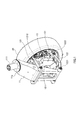
- FIG. 1 is a perspective view showing an embodiment of a suspension unit.
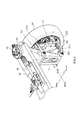
- FIG. 2 is a front view (A) and a side view (B) of the suspension unit.
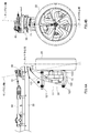
- FIG. 3 is a perspective view showing a state in which the suspension unit is used for the front wheels and assembled to the chassis frame.
- FIG. 4 is a front view (A) and a side view (B) showing a state in which the suspension unit is assembled to the chassis frame.
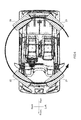
- FIG. 5 is a view showing a vehicle that uses a suspension unit in a state where the roof is not provided, viewed from above and the wheels are overlapped so that the direction of the wheels can be easily understood.
- FIG. 6 is a view showing a vehicle using the suspension unit in a state where the roof is not provided, viewed from above and the wheels are overlapped so that the directions of the wheels can be easily understood.
- FIG. 1 is a perspective view showing an embodiment of a suspension unit.
- the suspension unit 10 illustrated in FIG. 1 is a double wishbone type, and mainly includes an upright 11, a suspension arm 12 (upper suspension arm 121, lower suspension arm 122), and a wheel mounting body 13. Have and.
- the upper suspension arm is appropriately referred to as “upper arm”.
- the lower suspension arm is appropriately referred to as a "lower arm”.
- the upright 11 is a base member to which the suspension arm 12 (upper arm 121, lower arm 122) and the like are attached.
- the upright 11 is attached to the chassis as described later.
- a shaft portion 111 is fixed so as to stand upright. As will be described later, this shaft portion 111 is inserted into the hole of the chassis to attach the upright 11 to the chassis.
- the upper arm 121 is a substantially U-shaped member having two arm portions arranged in parallel with each other and a connecting portion that connects the proximal ends of both arms.
- a hole for passing the pivot shaft 1211 is formed near the base end of the arm portion of the upper arm 121.
- a hole for passing the pivot shaft 1212 is formed near the tip of the arm portion of the upper arm 121.
- the upper arm 121 is supported by the upright 11 via a pivot shaft 1211. In this state, the connecting portion of the upper arm 121 is located on the back side of the upright 11 (the side opposite to the wheel 20).
- the lower arm 122 is a substantially H-shaped member having a base short tip length, which has two arm portions and a connecting portion that connects the two. In order to secure a clearance with the wheel mounting body 13, the two arm portions are shaped such that the vicinity of the distal end is separated from the vicinity of the proximal end.
- the connecting part connects the lower parts of the two arm parts.
- a hole for inserting the pivot shaft 1221 is formed near the base end of the arm portion of the lower arm 122.
- a hole for passing the pivot shaft 1222 is formed near the tip of the arm portion of the lower arm 122.
- the lower arm 122 is supported by the upright 11 via a pivot shaft 1221. In this state, the connecting portion of the lower arm 122 is located on the front side of the upright 11 (the same side as the wheel 20).
- the wheel mounting body 13 is a member for mounting the wheel 20 via the axle.
- the wheel mounting body 13 is mounted near the tips of the upper arm 121 and the lower arm 122 via a pivot shaft 1212 and a pivot shaft 1222.
- the wheel mounting body 13 illustrated in FIG. 1 is a motor that drives the wheels 20, and a housing 131 is mounted on the upper arm 121 and the lower arm 122.
- a hole for attaching the lower arm 122 is formed at the lower end of the upright 11.
- the lower arm 122 is swingably attached to the upright 11 by aligning the hole near the base end of the arm portion of the lower arm 122 and inserting the pivot shaft 1221.
- a hole for attaching the upper arm 121 is formed directly above the hole into which the pivot shaft 1221 is inserted.
- the hole near the base end of the arm portion of the upper arm 121 is aligned with this hole, and the pivot shaft 1211 is inserted, whereby the upper arm 121 is swingably attached to the upright 11.
- the lower arm 122 is longer than the upper arm 121.
- the tip of the upper arm 121 does not reach the wheel 20 in front view, but the tip of the lower arm 122 reaches the wheel 20. That is, when viewed from the front, the tip of the lower arm 122 is located outside the tip of the upper arm 121.
- the arm portion of the lower arm 122 has a shape that extends downward from the vicinity of the proximal end toward the distal end, and extends upward from the middle. With such a shape, a clearance between the lower arm 122 and the wheel mounting body 13 is secured.
- the shock absorber 30 is connected to the rear surface of the wheel mounting body 13 and the upright 11. The shock from the road surface is alleviated by the shock absorber 30.
- FIG. 3 is a perspective view showing a state in which the suspension unit described above is used for the front wheels and assembled to the chassis frame.
- -Hole holes are formed near the left and right ends of the chassis frame 50, and bearings are fitted in these holes.
- the upright 11 By inserting the shaft portion 111 of the upright 11 so as to penetrate through the inside of the bearing, the upright 11 is rotatably assembled to the chassis frame 50 with the shaft portion 111 as a rotation center.
- a lever 40 is fixedly attached to the tip of the shaft 111.
- a steering gear box 60 is attached to the chassis frame 50.
- a tie rod 61 extending from the steering gear box 60 is connected to the lever 40, and the lever 40 is moved according to a steering wheel operation of a driver. Then, the upright 11 rotates about the shaft 111 as the center of rotation.
- FIG. 4A is a front view showing a state where the suspension unit is assembled to the chassis frame
- FIG. 4B is a side view showing a state where the suspension unit is assembled to the chassis frame.
- the upright 11 rotates about the shaft 111 as the center of rotation according to the steering wheel operation of the driver. That is, the rotation center axis of the shaft portion 111 corresponds to the kingpin axis.
- a top surface 11a (an assembly surface of the chassis frame 50) 11a of the upright 11 is inclined with respect to a horizontal plane.
- the shaft portion 111 is fixed to the top surface 11a so as to stand upright. That is, the shaft portion 111 is inclined with respect to the vertical line.
- the axis of rotation of the shaft 111 corresponds to the kingpin axis. Therefore, the kingpin tilt angle and the camber angle can be easily changed only by changing the tilt angle of the shaft portion 111 (the tilt angle of the top surface 11a).
- a top surface 11a of the upright 11 (an assembly surface to the chassis frame 50) is inclined with respect to the horizontal.
- the shaft portion 111 is fixed to the top surface 11a so as to stand upright.
- the rotation center axis of the shaft portion 111 corresponds to the kingpin axis. Therefore, the caster angle can be easily changed only by changing the inclination angle of the top surface 11a.
- the scrub radius also called the kingpin offset
- the point at which the kingpin axis intersects the ground can be changed only by changing the top surface 11a, so that the scrub radius can be easily changed. It is also easy to have a scrub radius of zero or a negative scrub radius, as shown in FIG. 4A.
- the suspension geometry such as the kingpin inclination angle, the camber angle, the caster angle, and the scrub radius can be freely set by simply changing the shape of the upright 11 (in particular, the inclination angle and the dimension of the top surface 11a), and an appropriate suspension It is easy to have a geometry.
- the rear wheel suspension unit should be fixed to the chassis frame 50 and assembled. In this way, a normal front wheel steering type vehicle can be obtained. In this case, since the rear wheel suspension unit does not rotate, it may be directly assembled to the chassis frame 50 without a bearing.
- the wheel mounting body 13 of the suspension unit for the rear wheels can be made into an all-wheel drive type vehicle by using a motor for driving the wheels 20. Further, unlike the one for the front wheels, if a motor for driving the wheels 20 is not used, the vehicle can be a front-wheel drive type vehicle. In this case, as the wheel mounting body 13, for example, one in which the axle is assembled to the housing 131 may be used.
- the in-wheel motor When adopting an in-wheel motor for the front wheels, in the conventional structure, the in-wheel motor would exist at the point of the ball joint that forms the king pin shaft, making it difficult to properly set the king pin shaft.
- the base member (upright 11) to which the suspension arm is swingably attached is provided.
- the base member is structured to rotate in response to the driver's operation of the steering wheel.
- flexibility in setting the kingpin axis has been created, and it becomes possible to freely set the suspension geometry such as the kingpin tilt angle, camber angle, and caster angle. In other words, it became easy to properly set the suspension geometry.
- the suspension unit since the suspension unit is integrally rotated, the suspension arm does not interfere with other components. Therefore, the steering angle is not limited.
- conventional products can be used without using a dedicated product, and the manufacturing cost can be kept low. You can also change the motor size and brake size.
- FIG. 5 is a view showing a vehicle that uses a suspension unit in a state where the roof is not provided, viewed from above and the wheels are overlapped so that the direction of the wheels can be easily understood.
- the suspension unit for the front wheels is mounted so as to rotate about the shaft portion 111, and the suspension unit for the rear wheels is fixed to the chassis frame 50 and assembled. It was being done.
- the suspension unit for the rear wheels also adopts the structure of FIGS. 3 and 4 similarly to the suspension unit for the front wheels, and is rotatable with respect to the chassis frame 50. It can be assembled.
- the suspension unit can be rotated integrally, so the suspension arm does not interfere with other parts. Therefore, the steering angle is not limited. It is also possible to rotate 90 degrees around the shaft portion 111 of the upright 11. Therefore, according to this second assembly mode, as shown in FIG. 5, the front wheels and the rear wheels can be oriented right beside.
- both the wheel mounting body 13 of the suspension unit for the front wheels and the wheel mounting body 13 of the suspension unit for the rear wheels are used as an all-wheel drive type vehicle that uses a motor for driving the wheels 20, the wheels are The vehicle can be moved laterally by driving each wheel while driving in a state of being directed to the side. Therefore, it is possible to realize a vehicle that can be efficiently parked in an extremely small space.
- a motor for driving the wheel 20 is used for the wheel mounting body 13 of the left or right (for example, left front wheel) suspension unit for the front wheels, and the motor is used for the other wheel mounting body 13 (for example, the right front wheel). do not use.
- a motor for driving the wheel 20 is used for the wheel mounting body 13 of the other left or right suspension unit (for example, the right rear wheel) for the rear wheels, and one wheel mounting body 13 (for example, the left rear wheel) is used. Do not use the motor.
- a motor that drives the wheels 20 may be used only for the wheel mounting bodies 13 of the suspension units that are diagonally arranged. Even in this case, as shown in FIG.
- FIG. 6 is a view showing a vehicle using the suspension unit in a state where the roof is not provided, viewed from above and the wheels are overlapped so that the directions of the wheels can be easily understood.
- the lever 40 is fixed to the tip of the shaft portion 111 of the upright 11, and the lever 40 is rotated by the tie rod 61 of the steering gear box 60.
- the structure for rotating the shaft portion 111 is not limited to such a structure.
- an actuator such as a motor may be attached to the shaft portion 111 of the upright 11 to rotate the shaft portion 111.
- the directions of the left and right wheels can be freely changed. Therefore, each wheel can be oriented as shown in FIG.
- the movement shown by the arrow in FIG. 6, that is, turning on the spot becomes possible, which also makes it possible to realize a vehicle that can be efficiently parked in a very small space.
- the motors that drive the wheels 20 are used for the wheel mounts 13 of all the suspension units, the motors that drive the wheels 20 are used only for the wheel mounts 13 of the suspension units diagonally arranged. May be.
- the double wishbone type suspension system was illustrated.
- the technical scope of the present invention is not intended to be limited to the double wishbone type.
- it may be applied to a strut type or a multi-link type.
Landscapes
- Engineering & Computer Science (AREA)
- Mechanical Engineering (AREA)
- Chemical & Material Sciences (AREA)
- Combustion & Propulsion (AREA)
- Transportation (AREA)
- Vehicle Body Suspensions (AREA)
Abstract
サスペンションユニットは、天面11aに直立する軸部111を備え、その軸部111が車台50の孔に挿入されて車台50に取り付けられる基部材11と、基部材11に揺動自在に取り付けられるサスペンションアーム12と、車輪20を組付可能であってサスペンションアーム12に組み付けられる車輪取付体13とを有する。
Description
この発明は、サスペンションユニット及び車両に関する。
発明者らは、自動運転車両やカーシェアリングの普及を見据えて、極小スペースに効率よく駐車可能な車両を開発中である。そのような車両では、横方向に移動できたり、その場で回転できることが望ましい。特開2016-55804号公報は、横方向移動や、その場回転を可能にする技術を開示する。
しかしながら、前述した従来の技術では、構造が複雑で、またサスペンションジオメトリーの自由度が制限され、適切なサスペンションジオメトリーを設定することが困難であった。
本発明は、このような従来の問題点に着目してなされた。本発明の目的は、適切なサスペンションジオメトリーを設定しやすく、極小スペースに効率のよい駐車を可能にするサスペンションユニット及び車両を提供することである。
本発明は以下のような解決手段によって前記課題を解決する。なお、理解を容易にするために本発明の実施形態に対応する符号を付するが、これに限定されるものではない。また符号を付して説明した構成は適宜代替しても改良してもよい。
ひとつの態様は、天面(11a)に直立する軸部(111)を備え、その軸部(111)が車台(50)の孔に挿入されて車台(50)に取り付けられる基部材(11)と、前記基部材(11)に揺動自在に取り付けられるサスペンションアーム(12)と、車輪(20)を組付可能であって前記サスペンションアーム(12)に組み付けられる車輪取付体(13)とを有するサスペンションユニット(10)である。
本発明の実施形態、本発明の利点は、添付の図面が参照されて以下に詳細に説明される。
図1は、サスペンションユニットの一実施形態を示す斜視図である。
図1に例示されているサスペンションユニット10は、ダブルウィッシュボーンタイプであり、主に、アップライト(upright)11と、サスペンションアーム12(アッパーサスペンションアーム121,ロワサスペンションアーム122)と、車輪取付体13とを有する。なお以下では、アッパーサスペンションアームは、適宜「アッパーアーム」と称される。ロワサスペンションアームは、適宜「ロワアーム」と称される。
アップライト11は、サスペンションアーム12(アッパーアーム121,ロワアーム122)などを取り付ける基部材である。アップライト11は、後述するように、車台に取り付けられる。アップライト11の天面11aには、軸部111が直立するように固設されている。後述するように、この軸部111が車台の孔に挿入されて、アップライト11が車台に取り付けられる。
アッパーアーム121は、互いに平行に配置された2本のアーム部と、両者の基端付近を連結する連結部とを有する略U状の部材である。アッパーアーム121のアーム部の基端付近には、ピボット軸1211を通すための孔が形成されている。アッパーアーム121のアーム部の先端付近には、ピボット軸1212を通すための孔が形成されている。アッパーアーム121は、ピボット軸1211を介してアップライト11に支持される。この状態で、アッパーアーム121の連結部は、アップライト11の裏側(車輪20とは反対側)に位置する。
ロワアーム122は、2本のアーム部と、両者を連結する連結部とを有する基短先長の略H状の部材である。2本のアーム部は、車輪取付体13とのクリアランスを確保するために、基端付近よりも先端付近が互いに離れるような形状にされている。連結部は、2本のアーム部の下方を連結している。ロワアーム122のアーム部の基端付近には、ピボット軸1221を通すための孔が形成されている。ロワアーム122のアーム部の先端付近には、ピボット軸1222を通すための孔が形成されている。ロワアーム122は、ピボット軸1221を介してアップライト11に支持される。この状態で、ロワアーム122の連結部は、アップライト11の表側(車輪20と同じ側)に位置する。
車輪取付体13は、車軸を介して車輪20を取り付ける部材である。車輪取付体13は、アッパーアーム121及びロワアーム122の先端付近に、ピボット軸1212及びピボット軸1222を介して取り付けられる。図1に例示される車輪取付体13は、車輪20を駆動するモーターであり、ハウジング131がアッパーアーム121及びロワアーム122に取り付けられている。
続いて、図2Aに示されているサスペンションユニットの正面図及び図2Bに示されているサスペンションユニットの側面図を参照して、サスペンションユニット10の構造についてさらに説明する。
図2Aに示されているように、アップライト11の下端には、ロワアーム122を取り付けるための孔が形成されている。この孔にロワアーム122のアーム部の基端付近の孔が合わされて、ピボット軸1221が挿入されることで、ロワアーム122がアップライト11に揺動自在に取り付けられる。
また、ピボット軸1221が挿入される孔の真上にアッパーアーム121を取り付けるための孔が形成されている。この孔にアッパーアーム121のアーム部の基端付近の孔が合わされて、ピボット軸1211が挿入されることで、アッパーアーム121がアップライト11に揺動自在に取り付けられる。
さらに、図2Aに示されているように、ロワアーム122は、アッパーアーム121よりも長い。アッパーアーム121及びロワアーム122がアップライト11に取り付けられた状態で、正面視において、アッパーアーム121の先端は、車輪20に達していないが、ロワアーム122の先端は、車輪20に達している。すなわち、正面視において、ロワアーム122の先端は、アッパーアーム121の先端よりも外側に位置している。
さらにまた、図2Aに示されているように、ロワアーム122のアーム部は、基端付近から先端側に進むにつれて下方に向かい、途中から上方に向かうように延設された形状である。このような形状であるので、ロワアーム122と車輪取付体13とのクリアランスが確保される。
また、図2Aに示されているように、ショックアブソーバー30が、車輪取付体13の背面とアップライト11とに連結されている。このショックアブソーバー30によって、路面からの衝撃が緩和される。
(サスペンションユニットの車台への第1組付態様)
図3は、上述のサスペンションユニットを前輪用に使用して、車台フレームに組み付けた状態を示す斜視図である。
図3は、上述のサスペンションユニットを前輪用に使用して、車台フレームに組み付けた状態を示す斜視図である。
車台フレーム50の左右両端付近には、孔が形成されており、この孔にベアリングが嵌合されている。このベアリングの内側を貫通するようにアップライト11の軸部111が挿入されることで、アップライト11が軸部111を回動中心として回動自在に車台フレーム50に組み付けられている。また軸部111の先端にはレバー40が固設されている。
車台フレーム50には、ステアリングギアボックス60が組み付けられている。レバー40には、ステアリングギアボックス60から延びるタイロッド61が接続されており、ドライバーのステアリングホイール操作に応じて、レバー40が動かされる。すると、軸部111を回動中心として、アップライト11が回動する。
図4Aは、サスペンションユニットを車台フレームに組み付けた状態を示す正面図であり、図4Bは、サスペンションユニットを車台フレームに組み付けた状態を示す側面図である。
上述したように、アップライト11は、ドライバーのステアリングホイール操作に応じて、軸部111を回動中心として回動する。すなわち、軸部111の回転中心軸線がキングピン軸に相当する。
図4Aに示されているように、アップライト11の天面(車台フレーム50への組付面)11aは、水平面に対して傾斜している。そして、上述のように、この天面11aに、軸部111が直立するように固設されている。すなわち、軸部111は、鉛直線に対して傾斜している。この軸部111の回転中心軸線がキングピン軸に相当する。したがって、軸部111の傾斜角度(天面11aの傾斜角度)を変更するだけで、キングピン傾角やキャンバー角を容易に変更することが可能である。
また、図4Bに示されているように、アップライト11の天面(車台フレーム50への組付面)11aは、水平に対して傾斜している。この天面11aに、軸部111が直立するように固設されている。軸部111の回転中心軸線がキングピン軸に相当する。したがって、天面11aの傾斜角度を変更するだけで、キャスター角を容易に変更することが可能である。
さらに、キングピン軸が地面と交わる点とタイヤ接地中心との距離がスクラブ半径と呼ばれ(キングピンオフセットとも呼ばれる)、これが過大であると、ステアリング操舵荷重の増大、路面からのキックバックの増大といった問題を生じる。これに対して、本実施形態の構造によれば、天面11aを変更するだけで、キングピン軸が地面と交わる点を変更できるので、スクラブ半径の変更も容易である。スクラブ半径をゼロにしたり、図4Aに示されるように、スクラブ半径をマイナスにすることも容易である。
したがって、アップライト11の形状(特に、天面11aの傾斜角度や寸法等)を変更するだけで、キングピン傾角,キャンバー角,キャスター角,スクラブ半径といったサスペンションジオメトリーを自由に設定でき、適切なサスペンションジオメトリーとすることが容易である。
後輪用のサスペンションユニットは、車台フレーム50に固設して組み付けるとよい。このようにすれば、通常の前輪操舵タイプの車両とすることができる。なお、この場合、後輪用のサスペンションユニットは回動しないので、ベアリングを介することなく、車台フレーム50に直接組み付けてよい。
後輪用のサスペンションユニットの車輪取付体13として、前輪用と同様に、車輪20を駆動するモーターを使用すれば、全輪駆動タイプの車両とすることができる。また、前輪用とは異なって、車輪20を駆動するモーターを使用しなければ、前輪駆動タイプの車両とすることができる。この場合、車輪取付体13としては、たとえば、ハウジング131に車軸が組み付けられているだけのものを使用すればよい。
前輪にインホイールモーターを採用する場合、従来構造ではキングピン軸を形成するボールジョイントのポイントにインホイールモーターが存在してしまうこととなってしまい、キングピン軸の適切な設定が困難であった。
これに対して、本実施形態によれば、サスペンションアームを揺動自在に取り付ける基部材(アップライト11)が設けられている。そして、この基部材が、ドライバーのステアリングホイール操作に応じて回動する構造とされている。このような構造が採用されることで、キングピン軸の設定に自由度が生まれ、キングピン傾角,キャンバー角,キャスター角といったサスペンションジオメトリーの自由な設定が可能になった。すなわち、サスペンションジオメトリーの適切な設定が容易にできるようになったのである。
また、サスペンションユニットが一体的に回動させられるので、サスペンションアームが他部品と干渉しない。したがって、舵角が制限されない。
サスペンションアーム等の部品は、専用品を用いることなく従来品を流用でき、製造コストを安価に抑えることができる。
またモーターサイズやブレーキサイズの変更も自在である。
また、サスペンションユニットが一体的に回動させられるので、サスペンションアームが他部品と干渉しない。したがって、舵角が制限されない。
サスペンションアーム等の部品は、専用品を用いることなく従来品を流用でき、製造コストを安価に抑えることができる。
またモーターサイズやブレーキサイズの変更も自在である。
(サスペンションユニットの車台への第2組付態様)
図5は、サスペンションユニットを使用する車両を屋根が無い状態で上方から見るとともに車輪の向きがわかりやすいように車輪を重ねて示した図である。
図5は、サスペンションユニットを使用する車両を屋根が無い状態で上方から見るとともに車輪の向きがわかりやすいように車輪を重ねて示した図である。
上述した第1組付態様では、前輪用のサスペンションユニットは、軸部111を回動中心として回動する要に取り付けられるとともに、後輪用のサスペンションユニットは、車台フレーム50に固設して組み付けられていた。
これに対して、この第2組付態様では、後輪用のサスペンションユニットにおいても、前輪用と同様に、図3及び図4の構造を採用して、車台フレーム50に対して回動自在に組み付けられる。
上述したように、サスペンションユニットは一体的に回動させられるので、サスペンションアームが他部品と干渉しない。したがって、舵角が制限されない。アップライト11の軸部111を回動中心として90度回動することも可能である。したがって、この第2組付態様によれば、図5に示すように、前輪及び後輪を真横に向けることもできる。
そして、前輪用のサスペンションユニットの車輪取付体13にも、後輪用のサスペンションユニットの車輪取付体13にも、車輪20を駆動するモーターを使用する全輪駆動タイプの車両としておけば、車輪を真横に向けた状態で各輪を駆動して走行することで、横方向に移動できる。よって、極小スペースに効率よく駐車可能な車両を実現することができる。
また、前輪用の左右のいずれか一方(たとえば左前輪)のサスペンションユニットの車輪取付体13に車輪20を駆動するモーターを使用するとともに、他方(たとえば右前輪)の車輪取付体13にはモーターを使用しない。そして後輪用の左右のいずれか他方(たとえば右後輪)のサスペンションユニットの車輪取付体13に車輪20を駆動するモーターを使用するとともに、一方(たとえば左後輪)の車輪取付体13にはモーターを使用しない。このように、対角に配置されるサスペンションユニットの車輪取付体13にのみ車輪20を駆動するモーターを使用してもよい。このようにしても、図5に示すように、輪を真横に向けた状態で対角の駆動輪を駆動することで、横方向移動が可能になる。二輪駆動タイプの車両であるので、全輪駆動タイプの車両よりも安価でありながら、極小スペースに効率よく駐車可能な車両を実現できる。
(サスペンションユニットの車台への第3組付態様)
図6は、サスペンションユニットを使用する車両を屋根が無い状態で上方から見るとともに車輪の向きがわかりやすいように車輪を重ねて示した図である。
図6は、サスペンションユニットを使用する車両を屋根が無い状態で上方から見るとともに車輪の向きがわかりやすいように車輪を重ねて示した図である。
上述においては、アップライト11の軸部111の先端にレバー40が固設されて、このレバー40がステアリングギアボックス60のタイロッド61によって回動させられる構造であった。しかしながら、軸部111を回動させる構造は、このような構造に限られない。たとえば、アップライト11の軸部111にモーター等のアクチュエーターを組み付けて、軸部111を回動させるようにしてもよい。このようにすれば、左右の車輪の向きをそれぞれ自由に変えることができる。したがって、各輪を図6に示されるような向きにすることも可能である。すると、図6に矢印に示すような動き、すなわちその場旋回が可能になり、これによっても、極小スペースに効率よく駐車可能な車両を実現することができる。この場合も、すべてのサスペンションユニットの車輪取付体13に車輪20を駆動するモーターを使用しても、対角に配置されるサスペンションユニットの車輪取付体13にのみ車輪20を駆動するモーターを使用してもよい。
以上、本発明の実施形態について説明したが、上記実施形態は本発明の適用例の一部を示したに過ぎず、本発明の技術的範囲を上記実施形態の具体的構成に限定する趣旨ではない。
たとえば、上記説明においては、ダブルウィッシュボーンタイプのサスペンション形式を例示した。しかしながら、本発明の技術的範囲をダブルウィッシュボーンタイプに限定する趣旨ではない。たとえばストラットタイプ,マルチリンクタイプなどに適用してもよい。
また図面に示される各部の具体的な形状やサイズ等は、一例に過ぎない。適宜変更可能である。
上記実施形態は、適宜組み合わせ可能である。
本願は2019年1月8日に日本国特許庁に出願された特願2019-923に基づく優先権を主張し、この出願の全ての内容は参照により本明細書に組み込まれる。
Claims (10)
- 天面に直立する軸部を備え、その軸部が車台の孔に挿入されて車台に取り付けられる基部材と、
前記基部材に揺動自在に取り付けられるサスペンションアームと、
車輪を取付可能であって前記サスペンションアームに組み付けられる車輪取付体と、
を有するサスペンションユニット。 - 請求項1に記載のサスペンションユニットにおいて、
前記車輪取付体は、前記車輪を駆動するモーターであり、ハウジングが前記サスペンションアームに組み付けられる、
サスペンションユニット。 - 請求項1又は請求項2に記載のサスペンションユニットにおいて、
正面視において、前記基部材が前記車台へ取り付けられた状態で、前記基部材の軸部は、鉛直線に対して傾斜している、
サスペンションユニット。 - 請求項1から請求項3までのいずれか1項に記載のサスペンションユニットにおいて、
前記基部材は、前記軸部が前記車台に組み込まれたベアリングの孔に挿入されることで前記軸部を回動中心として回動自在に前記車台に取り付けられる、
サスペンションユニット。 - 請求項4に記載のサスペンションユニットにおいて、
前記軸部に固設され、ステアリングギアボックスから延びるタイロッドに接続されるレバーを有し、
前記基部材は、前記タイロッドの動きに応じて回動する、
サスペンションユニット。 - 請求項4に記載のサスペンションユニットにおいて、
前記軸部に組み付けられるアクチュエーターを有し、
前記基部材は、前記アクチュエーターによって回動させられる、
サスペンションユニット。 - 前記車台に回動自在に取り付けられ、右前輪を組み付ける請求項4から請求項6までのいずれか1項に記載のサスペンションユニットと、
前記車台に回動自在に取り付けられ、左前輪を組み付ける請求項4から請求項6までのいずれか1項に記載のサスペンションユニットと、
前記車台に固設され、右後輪を組み付ける請求項1から請求項3までのいずれか1項に記載のサスペンションユニットと、
前記車台に固設され、左後輪を組み付ける請求項1から請求項3までのいずれか1項に記載のサスペンションユニットと、
を有する車両。 - 前記車台に回動自在に取り付けられ、右前輪を組み付ける請求項4から請求項6までのいずれか1項に記載のサスペンションユニットと、
前記車台に回動自在に取り付けられ、左前輪を組み付ける請求項4から請求項6までのいずれか1項に記載のサスペンションユニットと、
前記車台に回動自在に取り付けられ、右後輪を組み付ける請求項4から請求項6までのいずれか1項に記載のサスペンションユニットと、
前記車台に回動自在に取り付けられ、左後輪を組み付ける請求項4から請求項6までのいずれか1項に記載のサスペンションユニットと、
を有する車両。 - 請求項7又は請求項8に記載の車両において、
前記右前輪を組み付けるサスペンションユニット,前記左前輪を組み付けるサスペンションユニット,前記右後輪を組み付けるサスペンションユニット及び前記左後輪を組み付けるサスペンションユニットのうち、少なくとも、平面視において対角に配置されるサスペンションユニットの車輪取付体は、車輪を駆動するモーターである、
車両。 - 請求項7又は請求項8に記載の車両において、
前記右前輪を組み付けるサスペンションユニット,前記左前輪を組み付けるサスペンションユニット,前記右後輪を組み付けるサスペンションユニット及び前記左後輪を組み付けるサスペンションユニットのすべてのサスペンションユニットの車輪取付体は、車輪を駆動するモーターである、
車両。
Priority Applications (2)
| Application Number | Priority Date | Filing Date | Title |
|---|---|---|---|
| JP2020565708A JP7095121B2 (ja) | 2019-01-08 | 2019-12-25 | サスペンションユニット及び車両 |
| EP19909048.1A EP3909831A4 (en) | 2019-01-08 | 2019-12-25 | Suspension unit and vehicle |
Applications Claiming Priority (2)
| Application Number | Priority Date | Filing Date | Title |
|---|---|---|---|
| JP2019000923 | 2019-01-08 | ||
| JP2019-000923 | 2019-01-18 |
Publications (1)
| Publication Number | Publication Date |
|---|---|
| WO2020145166A1 true WO2020145166A1 (ja) | 2020-07-16 |
Family
ID=71520675
Family Applications (1)
| Application Number | Title | Priority Date | Filing Date |
|---|---|---|---|
| PCT/JP2019/051008 Ceased WO2020145166A1 (ja) | 2019-01-08 | 2019-12-25 | サスペンションユニット及び車両 |
Country Status (3)
| Country | Link |
|---|---|
| EP (1) | EP3909831A4 (ja) |
| JP (1) | JP7095121B2 (ja) |
| WO (1) | WO2020145166A1 (ja) |
Cited By (5)
| Publication number | Priority date | Publication date | Assignee | Title |
|---|---|---|---|---|
| CN114506183A (zh) * | 2020-11-17 | 2022-05-17 | 现代摩比斯株式会社 | 独立驱动轮模块及其安装方法 |
| KR20230075724A (ko) * | 2021-11-23 | 2023-05-31 | 현대모비스 주식회사 | 차량용 코너 모듈 장치 |
| US12077234B2 (en) | 2020-12-31 | 2024-09-03 | Ree Automotive Ltd. | Steering and suspension mechanism |
| WO2025074887A1 (ja) * | 2023-10-05 | 2025-04-10 | F2テクノ株式会社 | ステアリングギアボックス及びサスペンションアッセンブリー及びステアリングシステム |
| US12491928B2 (en) * | 2021-12-08 | 2025-12-09 | Hyundai Motor Company | Independent corner module |
Families Citing this family (1)
| Publication number | Priority date | Publication date | Assignee | Title |
|---|---|---|---|---|
| CN116442758A (zh) * | 2022-01-10 | 2023-07-18 | 现代摩比斯株式会社 | 用于车辆的角模块装置 |
Citations (7)
| Publication number | Priority date | Publication date | Assignee | Title |
|---|---|---|---|---|
| JPH07276946A (ja) * | 1994-04-15 | 1995-10-24 | Toyota Autom Loom Works Ltd | 油圧四輪駆動車における懸架装置の取付構造 |
| JPH07276151A (ja) * | 1994-04-08 | 1995-10-24 | Toyota Motor Corp | ソレノイドバルブの組付確認方法及び組付確認装置 |
| JP2012045979A (ja) * | 2010-08-24 | 2012-03-08 | Jtekt Corp | 車両用操舵装置 |
| JP2012121391A (ja) * | 2010-12-07 | 2012-06-28 | Ntn Corp | ステアリング装置 |
| JP2015098262A (ja) * | 2013-11-19 | 2015-05-28 | Ntn株式会社 | 駆動転舵モジュールと、駆動転舵モジュールを備えた車両 |
| JP2016055804A (ja) | 2014-09-11 | 2016-04-21 | Ntn株式会社 | ステアリング装置及び車両の走行モードの切り替え方法 |
| JP2019000923A (ja) | 2017-06-13 | 2019-01-10 | 川崎重工業株式会社 | 多関節ロボットの機構モデルパラメータ推定方法 |
Family Cites Families (5)
| Publication number | Priority date | Publication date | Assignee | Title |
|---|---|---|---|---|
| JPH07276951A (ja) * | 1994-04-15 | 1995-10-24 | Toyota Autom Loom Works Ltd | 路面傾斜角度表示装置 |
| JP2013103665A (ja) * | 2011-11-16 | 2013-05-30 | Nissan Motor Co Ltd | インホイールモータ駆動車輪の転舵装置 |
| US9102331B2 (en) * | 2013-09-20 | 2015-08-11 | GM Global Technology Operations LLC | Multi-functional electric module for a vehicle |
| KR101793169B1 (ko) * | 2016-08-26 | 2017-11-03 | 주식회사 마루이엔지 | 전동식 구동 바퀴의 조향축 회전 장치 |
| DE102017106810A1 (de) * | 2017-03-29 | 2018-10-04 | Emm! Solutions Gmbh | Radaufhängung |
-
2019
- 2019-12-25 JP JP2020565708A patent/JP7095121B2/ja active Active
- 2019-12-25 WO PCT/JP2019/051008 patent/WO2020145166A1/ja not_active Ceased
- 2019-12-25 EP EP19909048.1A patent/EP3909831A4/en not_active Withdrawn
Patent Citations (7)
| Publication number | Priority date | Publication date | Assignee | Title |
|---|---|---|---|---|
| JPH07276151A (ja) * | 1994-04-08 | 1995-10-24 | Toyota Motor Corp | ソレノイドバルブの組付確認方法及び組付確認装置 |
| JPH07276946A (ja) * | 1994-04-15 | 1995-10-24 | Toyota Autom Loom Works Ltd | 油圧四輪駆動車における懸架装置の取付構造 |
| JP2012045979A (ja) * | 2010-08-24 | 2012-03-08 | Jtekt Corp | 車両用操舵装置 |
| JP2012121391A (ja) * | 2010-12-07 | 2012-06-28 | Ntn Corp | ステアリング装置 |
| JP2015098262A (ja) * | 2013-11-19 | 2015-05-28 | Ntn株式会社 | 駆動転舵モジュールと、駆動転舵モジュールを備えた車両 |
| JP2016055804A (ja) | 2014-09-11 | 2016-04-21 | Ntn株式会社 | ステアリング装置及び車両の走行モードの切り替え方法 |
| JP2019000923A (ja) | 2017-06-13 | 2019-01-10 | 川崎重工業株式会社 | 多関節ロボットの機構モデルパラメータ推定方法 |
Non-Patent Citations (1)
| Title |
|---|
| See also references of EP3909831A4 |
Cited By (13)
| Publication number | Priority date | Publication date | Assignee | Title |
|---|---|---|---|---|
| CN114506183B (zh) * | 2020-11-17 | 2023-07-18 | 现代摩比斯株式会社 | 独立驱动轮模块及其安装方法 |
| KR20220067219A (ko) * | 2020-11-17 | 2022-05-24 | 현대모비스 주식회사 | 독립 구동휠 모듈 및 이의 장착 방법 |
| EP4000970A1 (en) * | 2020-11-17 | 2022-05-25 | Hyundai Mobis Co., Ltd. | Independently driving wheel module and mounting method thereof |
| US11577783B2 (en) | 2020-11-17 | 2023-02-14 | Hyundai Mobis Co., Ltd. | Independently driving wheel module and mounting method thereof |
| US20230143749A1 (en) * | 2020-11-17 | 2023-05-11 | Hyundai Mobis Co., Ltd. | Independently driving wheel module and mounting method thereof |
| CN114506183A (zh) * | 2020-11-17 | 2022-05-17 | 现代摩比斯株式会社 | 独立驱动轮模块及其安装方法 |
| US11851103B2 (en) | 2020-11-17 | 2023-12-26 | Hyundai Mobis Co., Ltd. | Independently driving wheel module and mounting method thereof |
| KR102886000B1 (ko) * | 2020-11-17 | 2025-11-12 | 현대모비스 주식회사 | 독립 구동휠 모듈 및 이의 장착 방법 |
| US12077234B2 (en) | 2020-12-31 | 2024-09-03 | Ree Automotive Ltd. | Steering and suspension mechanism |
| KR20230075724A (ko) * | 2021-11-23 | 2023-05-31 | 현대모비스 주식회사 | 차량용 코너 모듈 장치 |
| KR102654193B1 (ko) | 2021-11-23 | 2024-04-03 | 현대모비스 주식회사 | 차량용 코너 모듈 장치 |
| US12491928B2 (en) * | 2021-12-08 | 2025-12-09 | Hyundai Motor Company | Independent corner module |
| WO2025074887A1 (ja) * | 2023-10-05 | 2025-04-10 | F2テクノ株式会社 | ステアリングギアボックス及びサスペンションアッセンブリー及びステアリングシステム |
Also Published As
| Publication number | Publication date |
|---|---|
| JPWO2020145166A1 (ja) | 2021-12-16 |
| EP3909831A4 (en) | 2022-11-09 |
| EP3909831A1 (en) | 2021-11-17 |
| JP7095121B2 (ja) | 2022-07-04 |
Similar Documents
| Publication | Publication Date | Title |
|---|---|---|
| JP7095121B2 (ja) | サスペンションユニット及び車両 | |
| JP3672344B2 (ja) | 車輪懸架装置 | |
| JP4966273B2 (ja) | リヤサスペンション装置 | |
| CN103476665B (zh) | 双轨车辆的可稍微转向的后轮的独立悬架 | |
| JP5584698B2 (ja) | 自動車用のセミトレーリングアーム車軸 | |
| JP3485276B2 (ja) | 車両の懸架装置 | |
| US20190329621A1 (en) | Vehicle suspension system | |
| JPH0569712A (ja) | 独立懸架式サスペンシヨン | |
| JP4765484B2 (ja) | サスペンション装置 | |
| US6231062B1 (en) | Suspension arrangement for a motor vehicle | |
| CN100522720C (zh) | 从动转向车架 | |
| JPH05124535A (ja) | 車両用懸架装置 | |
| US20050247502A1 (en) | Axle system with steering capability | |
| CN118024797A (zh) | 转向角模块 | |
| WO2016181795A1 (ja) | インホイールモータ駆動装置用サスペンション構造 | |
| JP2009040208A (ja) | 車両懸架装置 | |
| JP2555309B2 (ja) | 車両のリヤサスペンシヨン装置 | |
| JP2708075B2 (ja) | 操舵輪懸架装置 | |
| JP2547570B2 (ja) | 自動車のサスペンション装置 | |
| JP3767078B2 (ja) | 操舵輪用サスペンション装置 | |
| JPH03253413A (ja) | 車両の懸架装置 | |
| JPS6332048Y2 (ja) | ||
| JP2547569B2 (ja) | 自動車のサスペンション装置 | |
| JPH0728961Y2 (ja) | 車両のリヤサスペンション装置 | |
| JP2020501987A (ja) | マルチトラックの自動車 |
Legal Events
| Date | Code | Title | Description |
|---|---|---|---|
| 121 | Ep: the epo has been informed by wipo that ep was designated in this application |
Ref document number: 19909048 Country of ref document: EP Kind code of ref document: A1 |
|
| DPE2 | Request for preliminary examination filed before expiration of 19th month from priority date (pct application filed from 20040101) | ||
| ENP | Entry into the national phase |
Ref document number: 2020565708 Country of ref document: JP Kind code of ref document: A |
|
| NENP | Non-entry into the national phase |
Ref country code: DE |
|
| ENP | Entry into the national phase |
Ref document number: 2019909048 Country of ref document: EP Effective date: 20210809 |