WO2020145317A1 - 方向性電磁鋼板及び方向性電磁鋼板の製造方法 - Google Patents
方向性電磁鋼板及び方向性電磁鋼板の製造方法 Download PDFInfo
- Publication number
- WO2020145317A1 WO2020145317A1 PCT/JP2020/000341 JP2020000341W WO2020145317A1 WO 2020145317 A1 WO2020145317 A1 WO 2020145317A1 JP 2020000341 W JP2020000341 W JP 2020000341W WO 2020145317 A1 WO2020145317 A1 WO 2020145317A1
- Authority
- WO
- WIPO (PCT)
- Prior art keywords
- steel sheet
- boron
- grain
- coating
- aluminum
- Prior art date
- Legal status (The legal status is an assumption and is not a legal conclusion. Google has not performed a legal analysis and makes no representation as to the accuracy of the status listed.)
- Ceased
Links
Images
Classifications
-
- C—CHEMISTRY; METALLURGY
- C23—COATING METALLIC MATERIAL; COATING MATERIAL WITH METALLIC MATERIAL; CHEMICAL SURFACE TREATMENT; DIFFUSION TREATMENT OF METALLIC MATERIAL; COATING BY VACUUM EVAPORATION, BY SPUTTERING, BY ION IMPLANTATION OR BY CHEMICAL VAPOUR DEPOSITION, IN GENERAL; INHIBITING CORROSION OF METALLIC MATERIAL OR INCRUSTATION IN GENERAL
- C23C—COATING METALLIC MATERIAL; COATING MATERIAL WITH METALLIC MATERIAL; SURFACE TREATMENT OF METALLIC MATERIAL BY DIFFUSION INTO THE SURFACE, BY CHEMICAL CONVERSION OR SUBSTITUTION; COATING BY VACUUM EVAPORATION, BY SPUTTERING, BY ION IMPLANTATION OR BY CHEMICAL VAPOUR DEPOSITION, IN GENERAL
- C23C18/00—Chemical coating by decomposition of either liquid compounds or solutions of the coating forming compounds, without leaving reaction products of surface material in the coating; Contact plating
- C23C18/02—Chemical coating by decomposition of either liquid compounds or solutions of the coating forming compounds, without leaving reaction products of surface material in the coating; Contact plating by thermal decomposition
- C23C18/12—Chemical coating by decomposition of either liquid compounds or solutions of the coating forming compounds, without leaving reaction products of surface material in the coating; Contact plating by thermal decomposition characterised by the deposition of inorganic material other than metallic material
- C23C18/1204—Chemical coating by decomposition of either liquid compounds or solutions of the coating forming compounds, without leaving reaction products of surface material in the coating; Contact plating by thermal decomposition characterised by the deposition of inorganic material other than metallic material inorganic material, e.g. non-oxide and non-metallic such as sulfides, nitrides based compounds
- C23C18/1208—Oxides, e.g. ceramics
- C23C18/1216—Metal oxides
-
- C—CHEMISTRY; METALLURGY
- C21—METALLURGY OF IRON
- C21D—MODIFYING THE PHYSICAL STRUCTURE OF FERROUS METALS; GENERAL DEVICES FOR HEAT TREATMENT OF FERROUS OR NON-FERROUS METALS OR ALLOYS; MAKING METAL MALLEABLE, e.g. BY DECARBURISATION OR TEMPERING
- C21D1/00—General methods or devices for heat treatment, e.g. annealing, hardening, quenching or tempering
- C21D1/26—Methods of annealing
-
- C—CHEMISTRY; METALLURGY
- C21—METALLURGY OF IRON
- C21D—MODIFYING THE PHYSICAL STRUCTURE OF FERROUS METALS; GENERAL DEVICES FOR HEAT TREATMENT OF FERROUS OR NON-FERROUS METALS OR ALLOYS; MAKING METAL MALLEABLE, e.g. BY DECARBURISATION OR TEMPERING
- C21D1/00—General methods or devices for heat treatment, e.g. annealing, hardening, quenching or tempering
- C21D1/74—Methods of treatment in inert gas, controlled atmosphere, vacuum or pulverulent material
- C21D1/76—Adjusting the composition of the atmosphere
-
- C—CHEMISTRY; METALLURGY
- C21—METALLURGY OF IRON
- C21D—MODIFYING THE PHYSICAL STRUCTURE OF FERROUS METALS; GENERAL DEVICES FOR HEAT TREATMENT OF FERROUS OR NON-FERROUS METALS OR ALLOYS; MAKING METAL MALLEABLE, e.g. BY DECARBURISATION OR TEMPERING
- C21D6/00—Heat treatment of ferrous alloys
- C21D6/008—Heat treatment of ferrous alloys containing Si
-
- C—CHEMISTRY; METALLURGY
- C21—METALLURGY OF IRON
- C21D—MODIFYING THE PHYSICAL STRUCTURE OF FERROUS METALS; GENERAL DEVICES FOR HEAT TREATMENT OF FERROUS OR NON-FERROUS METALS OR ALLOYS; MAKING METAL MALLEABLE, e.g. BY DECARBURISATION OR TEMPERING
- C21D8/00—Modifying the physical properties of ferrous metals or ferrous alloys by deformation combined with, or followed by, heat treatment
- C21D8/12—Modifying the physical properties of ferrous metals or ferrous alloys by deformation combined with, or followed by, heat treatment during manufacturing of articles with special electromagnetic properties
- C21D8/1244—Modifying the physical properties of ferrous metals or ferrous alloys by deformation combined with, or followed by, heat treatment during manufacturing of articles with special electromagnetic properties characterised by the heat treatment
- C21D8/1272—Final recrystallisation annealing
-
- C—CHEMISTRY; METALLURGY
- C21—METALLURGY OF IRON
- C21D—MODIFYING THE PHYSICAL STRUCTURE OF FERROUS METALS; GENERAL DEVICES FOR HEAT TREATMENT OF FERROUS OR NON-FERROUS METALS OR ALLOYS; MAKING METAL MALLEABLE, e.g. BY DECARBURISATION OR TEMPERING
- C21D8/00—Modifying the physical properties of ferrous metals or ferrous alloys by deformation combined with, or followed by, heat treatment
- C21D8/12—Modifying the physical properties of ferrous metals or ferrous alloys by deformation combined with, or followed by, heat treatment during manufacturing of articles with special electromagnetic properties
- C21D8/1277—Modifying the physical properties of ferrous metals or ferrous alloys by deformation combined with, or followed by, heat treatment during manufacturing of articles with special electromagnetic properties involving a particular surface treatment
- C21D8/1283—Application of a separating or insulating coating
-
- C—CHEMISTRY; METALLURGY
- C21—METALLURGY OF IRON
- C21D—MODIFYING THE PHYSICAL STRUCTURE OF FERROUS METALS; GENERAL DEVICES FOR HEAT TREATMENT OF FERROUS OR NON-FERROUS METALS OR ALLOYS; MAKING METAL MALLEABLE, e.g. BY DECARBURISATION OR TEMPERING
- C21D8/00—Modifying the physical properties of ferrous metals or ferrous alloys by deformation combined with, or followed by, heat treatment
- C21D8/12—Modifying the physical properties of ferrous metals or ferrous alloys by deformation combined with, or followed by, heat treatment during manufacturing of articles with special electromagnetic properties
- C21D8/1277—Modifying the physical properties of ferrous metals or ferrous alloys by deformation combined with, or followed by, heat treatment during manufacturing of articles with special electromagnetic properties involving a particular surface treatment
- C21D8/1288—Application of a tension-inducing coating
-
- C—CHEMISTRY; METALLURGY
- C21—METALLURGY OF IRON
- C21D—MODIFYING THE PHYSICAL STRUCTURE OF FERROUS METALS; GENERAL DEVICES FOR HEAT TREATMENT OF FERROUS OR NON-FERROUS METALS OR ALLOYS; MAKING METAL MALLEABLE, e.g. BY DECARBURISATION OR TEMPERING
- C21D9/00—Heat treatment, e.g. annealing, hardening, quenching or tempering, adapted for particular articles; Furnaces therefor
- C21D9/46—Heat treatment, e.g. annealing, hardening, quenching or tempering, adapted for particular articles; Furnaces therefor for sheet metals
-
- C—CHEMISTRY; METALLURGY
- C23—COATING METALLIC MATERIAL; COATING MATERIAL WITH METALLIC MATERIAL; CHEMICAL SURFACE TREATMENT; DIFFUSION TREATMENT OF METALLIC MATERIAL; COATING BY VACUUM EVAPORATION, BY SPUTTERING, BY ION IMPLANTATION OR BY CHEMICAL VAPOUR DEPOSITION, IN GENERAL; INHIBITING CORROSION OF METALLIC MATERIAL OR INCRUSTATION IN GENERAL
- C23C—COATING METALLIC MATERIAL; COATING MATERIAL WITH METALLIC MATERIAL; SURFACE TREATMENT OF METALLIC MATERIAL BY DIFFUSION INTO THE SURFACE, BY CHEMICAL CONVERSION OR SUBSTITUTION; COATING BY VACUUM EVAPORATION, BY SPUTTERING, BY ION IMPLANTATION OR BY CHEMICAL VAPOUR DEPOSITION, IN GENERAL
- C23C18/00—Chemical coating by decomposition of either liquid compounds or solutions of the coating forming compounds, without leaving reaction products of surface material in the coating; Contact plating
- C23C18/02—Chemical coating by decomposition of either liquid compounds or solutions of the coating forming compounds, without leaving reaction products of surface material in the coating; Contact plating by thermal decomposition
- C23C18/12—Chemical coating by decomposition of either liquid compounds or solutions of the coating forming compounds, without leaving reaction products of surface material in the coating; Contact plating by thermal decomposition characterised by the deposition of inorganic material other than metallic material
- C23C18/1229—Composition of the substrate
- C23C18/1241—Metallic substrates
-
- C—CHEMISTRY; METALLURGY
- C23—COATING METALLIC MATERIAL; COATING MATERIAL WITH METALLIC MATERIAL; CHEMICAL SURFACE TREATMENT; DIFFUSION TREATMENT OF METALLIC MATERIAL; COATING BY VACUUM EVAPORATION, BY SPUTTERING, BY ION IMPLANTATION OR BY CHEMICAL VAPOUR DEPOSITION, IN GENERAL; INHIBITING CORROSION OF METALLIC MATERIAL OR INCRUSTATION IN GENERAL
- C23C—COATING METALLIC MATERIAL; COATING MATERIAL WITH METALLIC MATERIAL; SURFACE TREATMENT OF METALLIC MATERIAL BY DIFFUSION INTO THE SURFACE, BY CHEMICAL CONVERSION OR SUBSTITUTION; COATING BY VACUUM EVAPORATION, BY SPUTTERING, BY ION IMPLANTATION OR BY CHEMICAL VAPOUR DEPOSITION, IN GENERAL
- C23C22/00—Chemical surface treatment of metallic material by reaction of the surface with a reactive liquid, leaving reaction products of surface material in the coating, e.g. conversion coatings, passivation of metals
- C23C22/05—Chemical surface treatment of metallic material by reaction of the surface with a reactive liquid, leaving reaction products of surface material in the coating, e.g. conversion coatings, passivation of metals using aqueous solutions
- C23C22/06—Chemical surface treatment of metallic material by reaction of the surface with a reactive liquid, leaving reaction products of surface material in the coating, e.g. conversion coatings, passivation of metals using aqueous solutions using aqueous acidic solutions with pH less than 6
- C23C22/48—Chemical surface treatment of metallic material by reaction of the surface with a reactive liquid, leaving reaction products of surface material in the coating, e.g. conversion coatings, passivation of metals using aqueous solutions using aqueous acidic solutions with pH less than 6 not containing phosphates, hexavalent chromium compounds, fluorides or complex fluorides, molybdates, tungstates, vanadates or oxalates
- C23C22/50—Treatment of iron or alloys based thereon
-
- C—CHEMISTRY; METALLURGY
- C23—COATING METALLIC MATERIAL; COATING MATERIAL WITH METALLIC MATERIAL; CHEMICAL SURFACE TREATMENT; DIFFUSION TREATMENT OF METALLIC MATERIAL; COATING BY VACUUM EVAPORATION, BY SPUTTERING, BY ION IMPLANTATION OR BY CHEMICAL VAPOUR DEPOSITION, IN GENERAL; INHIBITING CORROSION OF METALLIC MATERIAL OR INCRUSTATION IN GENERAL
- C23C—COATING METALLIC MATERIAL; COATING MATERIAL WITH METALLIC MATERIAL; SURFACE TREATMENT OF METALLIC MATERIAL BY DIFFUSION INTO THE SURFACE, BY CHEMICAL CONVERSION OR SUBSTITUTION; COATING BY VACUUM EVAPORATION, BY SPUTTERING, BY ION IMPLANTATION OR BY CHEMICAL VAPOUR DEPOSITION, IN GENERAL
- C23C22/00—Chemical surface treatment of metallic material by reaction of the surface with a reactive liquid, leaving reaction products of surface material in the coating, e.g. conversion coatings, passivation of metals
- C23C22/05—Chemical surface treatment of metallic material by reaction of the surface with a reactive liquid, leaving reaction products of surface material in the coating, e.g. conversion coatings, passivation of metals using aqueous solutions
- C23C22/60—Chemical surface treatment of metallic material by reaction of the surface with a reactive liquid, leaving reaction products of surface material in the coating, e.g. conversion coatings, passivation of metals using aqueous solutions using alkaline aqueous solutions with pH greater than 8
- C23C22/62—Treatment of iron or alloys based thereon
-
- C—CHEMISTRY; METALLURGY
- C23—COATING METALLIC MATERIAL; COATING MATERIAL WITH METALLIC MATERIAL; CHEMICAL SURFACE TREATMENT; DIFFUSION TREATMENT OF METALLIC MATERIAL; COATING BY VACUUM EVAPORATION, BY SPUTTERING, BY ION IMPLANTATION OR BY CHEMICAL VAPOUR DEPOSITION, IN GENERAL; INHIBITING CORROSION OF METALLIC MATERIAL OR INCRUSTATION IN GENERAL
- C23C—COATING METALLIC MATERIAL; COATING MATERIAL WITH METALLIC MATERIAL; SURFACE TREATMENT OF METALLIC MATERIAL BY DIFFUSION INTO THE SURFACE, BY CHEMICAL CONVERSION OR SUBSTITUTION; COATING BY VACUUM EVAPORATION, BY SPUTTERING, BY ION IMPLANTATION OR BY CHEMICAL VAPOUR DEPOSITION, IN GENERAL
- C23C22/00—Chemical surface treatment of metallic material by reaction of the surface with a reactive liquid, leaving reaction products of surface material in the coating, e.g. conversion coatings, passivation of metals
- C23C22/73—Chemical surface treatment of metallic material by reaction of the surface with a reactive liquid, leaving reaction products of surface material in the coating, e.g. conversion coatings, passivation of metals characterised by the process
- C23C22/74—Chemical surface treatment of metallic material by reaction of the surface with a reactive liquid, leaving reaction products of surface material in the coating, e.g. conversion coatings, passivation of metals characterised by the process for obtaining burned-in conversion coatings
-
- H—ELECTRICITY
- H01—ELECTRIC ELEMENTS
- H01F—MAGNETS; INDUCTANCES; TRANSFORMERS; SELECTION OF MATERIALS FOR THEIR MAGNETIC PROPERTIES
- H01F1/00—Magnets or magnetic bodies characterised by the magnetic materials therefor; Selection of materials for their magnetic properties
- H01F1/01—Magnets or magnetic bodies characterised by the magnetic materials therefor; Selection of materials for their magnetic properties of inorganic materials
- H01F1/03—Magnets or magnetic bodies characterised by the magnetic materials therefor; Selection of materials for their magnetic properties of inorganic materials characterised by their coercivity
- H01F1/12—Magnets or magnetic bodies characterised by the magnetic materials therefor; Selection of materials for their magnetic properties of inorganic materials characterised by their coercivity of soft-magnetic materials
- H01F1/14—Magnets or magnetic bodies characterised by the magnetic materials therefor; Selection of materials for their magnetic properties of inorganic materials characterised by their coercivity of soft-magnetic materials metals or alloys
- H01F1/147—Alloys characterised by their composition
-
- H—ELECTRICITY
- H01—ELECTRIC ELEMENTS
- H01F—MAGNETS; INDUCTANCES; TRANSFORMERS; SELECTION OF MATERIALS FOR THEIR MAGNETIC PROPERTIES
- H01F1/00—Magnets or magnetic bodies characterised by the magnetic materials therefor; Selection of materials for their magnetic properties
- H01F1/01—Magnets or magnetic bodies characterised by the magnetic materials therefor; Selection of materials for their magnetic properties of inorganic materials
- H01F1/03—Magnets or magnetic bodies characterised by the magnetic materials therefor; Selection of materials for their magnetic properties of inorganic materials characterised by their coercivity
- H01F1/12—Magnets or magnetic bodies characterised by the magnetic materials therefor; Selection of materials for their magnetic properties of inorganic materials characterised by their coercivity of soft-magnetic materials
- H01F1/14—Magnets or magnetic bodies characterised by the magnetic materials therefor; Selection of materials for their magnetic properties of inorganic materials characterised by their coercivity of soft-magnetic materials metals or alloys
- H01F1/16—Magnets or magnetic bodies characterised by the magnetic materials therefor; Selection of materials for their magnetic properties of inorganic materials characterised by their coercivity of soft-magnetic materials metals or alloys in the form of sheets
- H01F1/18—Magnets or magnetic bodies characterised by the magnetic materials therefor; Selection of materials for their magnetic properties of inorganic materials characterised by their coercivity of soft-magnetic materials metals or alloys in the form of sheets with insulating coating
-
- C—CHEMISTRY; METALLURGY
- C21—METALLURGY OF IRON
- C21D—MODIFYING THE PHYSICAL STRUCTURE OF FERROUS METALS; GENERAL DEVICES FOR HEAT TREATMENT OF FERROUS OR NON-FERROUS METALS OR ALLOYS; MAKING METAL MALLEABLE, e.g. BY DECARBURISATION OR TEMPERING
- C21D2201/00—Treatment for obtaining particular effects
- C21D2201/05—Grain orientation
-
- C—CHEMISTRY; METALLURGY
- C22—METALLURGY; FERROUS OR NON-FERROUS ALLOYS; TREATMENT OF ALLOYS OR NON-FERROUS METALS
- C22C—ALLOYS
- C22C38/00—Ferrous alloys, e.g. steel alloys
- C22C38/02—Ferrous alloys, e.g. steel alloys containing silicon
Definitions
- the present invention relates to a grain-oriented electrical steel sheet and a method for manufacturing a grain-oriented electrical steel sheet.
- the grain-oriented electrical steel sheet has a crystal structure having ⁇ 110 ⁇ 001> as a main orientation and is often used as an iron core material of a transformer. In particular, a material having a small iron loss is required to reduce energy loss. ing.
- Patent Document 1 discloses a method of irradiating a laser beam on the surface of a steel sheet after finish annealing to give a local strain, thereby subdividing a magnetic domain as a means for reducing the iron loss of a grain-oriented electrical steel sheet.
- Patent Document 2 discloses a magnetic domain refining means that does not lose its effect even after performing stress relief annealing (stress relief annealing) after core processing.
- the grain-oriented electrical steel sheet includes a primary coating mainly composed of forsterite produced by a reaction between an oxide on the surface of the steel sheet and an annealing separator in the finish annealing step, and colloidal silica and phosphorus disclosed in Patent Document 3 and the like.
- a tension of about 10 MPa is applied at a plate thickness of 0.23 mm by the two layers of the secondary coating mainly composed of the amorphous material produced by baking the coating liquid mainly containing an acid salt.
- Patent Document 4 proposes a grain-oriented electrical steel sheet having a coating mainly composed of aluminum borate crystals on its surface.
- the film In order for a film to become a high-strength film, it is required that the film has a high Young's modulus and a small thermal expansion coefficient. Generally, crystals have a higher Young's modulus than amorphous ones.
- the coating film made of aluminum borate described in Patent Document 4 has a higher Young's modulus than the conventional amorphous coating film made of silica and phosphate because the main constituent is crystalline. Since the coefficient of thermal expansion is also sufficiently low, it is possible to obtain a higher tension than the film disclosed in Patent Document 3 in combination with the effect of Young's modulus.
- An object of the present invention is to provide a grain-oriented electrical steel sheet having an aluminum borate coating capable of imparting a larger tension than before and a method for manufacturing the grain-oriented electrical steel sheet.
- the present inventors considered that in order to obtain a higher tension in the aluminum borate coating, it is necessary to clarify the relationship between the element distribution in the coating and the tension, and to clarify the conditions under which a high tension is obtained. As a result of intensive studies, it was found that high tension can be obtained when the amount of boron near the interface between the coating and the steel sheet is large.
- the present invention has been made based on the above findings, and the gist thereof is as follows.
- a grain-oriented electrical steel sheet comprising: heating the steel sheet to a temperature of 750° C. at an average rate of 10 to 100° C./second and heat-treating it in a temperature range of 750 to 1000° C. for 20 to 120 seconds. Manufacturing method.
- the grain-oriented electrical steel sheet according to this embodiment includes a steel sheet (base steel sheet) and an insulating coating formed on the steel sheet and made of an oxide containing aluminum and boron.
- the steel plate (base steel plate) that can be used in this embodiment is not particularly limited as long as secondary reconstituted products have been completed.
- the steel sheet generally used as the base steel sheet is a steel sheet having a forsterite primary coating formed during finish annealing (secondary reannealing annealing), which can be used in the present embodiment.
- an insulating coating made of an oxide containing aluminum and boron is provided on the surface of the steel sheet.
- the oxide of the insulating coating contains a crystalline oxide, and the emission intensity of boron with respect to aluminum at the interface between the insulating coating and the steel sheet is measured by glow discharge optical emission spectroscopy (GDS).
- GDS glow discharge optical emission spectroscopy
- the maximum value of the ratio B/Al is 2.5 times or more and 4.0 times or less the emission intensity ratio B/Al of boron to aluminum in the insulating coating. This improves the tension of the grain-oriented electrical steel sheet.
- the present inventor investigated and studied improvement of the characteristics of the insulating film. As a result, they have found that a grain-oriented electrical steel sheet having high tension can be obtained by controlling the amount of boron near the interface between the insulating coating (tension coating) and the steel sheet. Specifically, regarding the emission intensity ratio of boron to aluminum in the insulating coating, when the maximum value at the interface between the insulating coating and the steel plate is 2.5 times or more and 4 times or less than the value in the insulating coating, high tension is applied. It has been found that a grain-oriented electrical steel sheet having a developed insulating coating can be obtained.
- the composition of the insulating coating in the depth direction there are various methods for measuring the composition of the insulating coating in the depth direction, but since the insulating coating containing aluminum borate is composed of boron, aluminum, and oxygen as components, it is possible to easily measure these by a glow discharge emission spectrometry method. Is appropriate. Specifically, the measurement result is processed as follows in order to quantify the element distribution in the insulating coating.
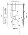
- the dependency of the emission intensity of both B/Al (hereinafter B/Al value) on the sputtering time is obtained, but as shown in FIG. It was revealed that high tension can be obtained when the maximum B/Al value (hereinafter, B/Al peak) near the interface between the insulating film and the steel sheet (hereinafter, interface) is high.
- B/Al peak the maximum B/Al value
- the interface is defined as a period from when the emission intensity of iron (Fe) rises from near 0 to a constant value.
- the region where the emission intensity of iron is near 0 is the analysis value in the insulating coating, and the region where the emission intensity of iron is not constant is almost constant is the analysis value in the steel plate. is there. Therefore, in the example shown in FIG. 1, the emission intensity of iron is almost 100 seconds from the discharge time of about 100 seconds when the emission intensity of iron rises from around 0 (near zero is a portion where the intensity is 5% or less of a constant value described later). 2 is a constant value (here, the "constant value" is the iron emission intensity value in the steel sheet, and the change from the previous 1-second average value is 0.05% or less with respect to the 1-second average value.
- the B/Al peak defined in the present invention is the peak showing the highest value in this region. Therefore, in FIG. 1, the peak designated as B/Al peak (Y) at a discharge time of about 120 seconds is the B/Al peak defined in the present invention, and the peak at a discharge time of about 10 seconds or about 190 seconds is the present invention. It does not correspond to the B/Al peak defined in.
- Table 1 shows an example of measurement conditions of the glow discharge emission spectroscopy for obtaining the emission intensities of Fe, B, and Al.
- the ratio of the emission intensity of each element represents a value that correlates with the composition ratio of these elements in the sputtered sample portion. Therefore, by measuring and calculating the B/Al value measured from the insulating coating and the ratio of the B/Al peak near the interface between the insulating coating and the steel sheet, the vicinity of the interface between the insulating coating and the steel sheet compared to the insulating coating is calculated. It is possible to relatively observe the amount of boron.
- a value obtained by dividing the emission intensity of boron measured as described above by the emission intensity of aluminum when the B/Al value in the insulating coating is X and the maximum value of the B/Al peak is Y, Y/X is 2.5 or more and 4.0 or less.
- the value of X is the entire B/Al value in the insulating coating, which is 0.001 or less from the previous 1-second average value for the 1-second average B/Al value. Is the average value of.
- Y/X is 2.5 or more and 4.0 or less means that the B/Al value at the interface is larger than the B/Al value in the insulating film, that is, based on the amount of Al. Then, it means that the amount of B at the interface is relatively larger than the amount of B in the insulating coating.
- boron oxide has a low melting point, it is considered that molten boron oxide accelerates the diffusion of elements in the portion of the insulating coating where the amount of boric acid is large. It is presumed that aluminum borate is likely to be formed easily when the element diffuses quickly, and it is considered that aluminum borate crystals are generated from a low temperature during the baking of the insulating film, resulting in a large amount of aluminum borate crystals. It is considered that when the amount of aluminum borate crystals increases due to the mechanism as described above, the film tension increases. In the present invention, attention is paid to the amount of B in order to secure the amount of boric acid at the interface, and a B/Al value normalized by the amount of Al also present in the insulating coating is defined.
- the lower limit was set to 2.5 times the value of.
- the B/Al peak is too high, the unreacted boron at the interface is increased, water easily reaches the surface of the steel sheet in a wet atmosphere, and problems such as rust may occur. Further, if the B/Al peak is too high, the film tension may rather decrease. It is presumed that the reason for this is that if B is excessively accumulated at the interface, the presence of boron in the insulating coating becomes non-uniform, and aluminum borate crystals are not sufficiently formed in a part of the insulating coating, resulting in a decrease in coating tension. To be done. For this reason, in the present invention, an upper limit is set for the value of the B/Al peak with respect to B/Al in the coating, and a good result can be obtained by increasing the value by 4.0.
- Y/X may be in the range described above, but in order to increase the number of aluminum borate crystals at the interface of the insulating coating with the steel sheet and further increase the coating tension, it is preferably 2.6 or more, more preferably It is preferably 2.7 or more. Further, Y/X is preferably 3.8 or less, and more preferably 3.5 or less in order to suppress excessive boron at the interface of the insulating coating with the steel sheet and to suppress the decrease in coating tension.
- the insulating coating of the grain-oriented electrical steel sheet according to this embodiment is too thick, the space factor of the base material steel sheet occupying the grain-oriented electrical steel sheet decreases, so it is preferable that it be as thin as possible according to the purpose.
- the thickness is preferably 5% or less. More preferably, 2 is% or less. Note that this coating thickness is the total thickness of both sides of the steel plate, and if it is exemplified in the case of the base material steel plate thickness of 0.23 mm, it is preferably 5% or less and the total of both sides is 11.5 ⁇ m or less. It is 5.75 ⁇ m or less.
- more preferable 2% or less is 4.6 ⁇ m or less in total on both surfaces, and 2.3 ⁇ m or less per one surface.
- the thickness is extremely thin, a sufficient effect cannot be obtained, and it is preferably 0.1 ⁇ m or more per one side of the steel sheet.
- the steel plate thickness is not particularly limited, and may be 0.10 mm or more and 0.35 mm or less as an example.
- a coating liquid containing a boron source and an aluminum source having a mass ratio of Al 2 O 3 /B 2 O 3 of 1.8 to 2.6 is applied to the surface of the steel sheet.
- the dew point is 0 to 40° C.
- the steel plate is heated in an inert gas atmosphere containing 0 to 25% by volume of hydrogen at a predetermined temperature in the range of 450 to 600° C. with an average heating rate of 2 to After heating at 5° C./sec, cooling to 200° C.
- the present inventor examined the process conditions in detail for the means for realizing the above-described insulating coating.
- the mass ratio Al 2 O 3 /B 2 O 3 of aluminum oxide and boron oxide is 1.8 in the base material steel sheet of the grain-oriented electrical steel sheet.
- This process consists of (i) diffusion of boron during temperature increase after coating solution drying and before aluminum borate crystallization, (ii) nucleation of aluminum borate crystals, and (iii) aluminum borate crystal growth.
- the manufacturing method of the grain-oriented electrical steel sheet according to the present embodiment will be described in detail with reference to the correspondence with the above processes (i) to (iii).
- the steel sheet as described above may be prepared. Specifically, a finish-annealing is performed by a conventionally known method to prepare a steel sheet on the surface of which a forsterite primary coating is formed. Good.
- the coating liquid contains a boron source and an aluminum source having a mass ratio of Al 2 O 3 /B 2 O 3 of 1.8 to 2.6.
- orthoboric acid represented by H 3 BO 3 is most preferable from the viewpoints of workability and cost, but metaboric acid represented by HBO 2 , boron oxide represented by B 2 O 3 , or these. Mixtures of can also be used.
- Examples of the aluminum source include aluminum oxide and aluminum oxide precursor compounds.
- Examples of the aluminum oxide precursor compound include aluminum oxide hydrate represented by Al 2 O 3 .mH 2 O such as boehmite, aluminum hydroxide, and various types of aluminum nitrate and aluminum chloride. Aluminum salts and the like are preferably used.
- the boron source and the aluminum source in the coating liquid are included so that the mass ratio in terms of Al 2 O 3 /B 2 O 3 is 1.8 to 2.6.
- the insulating coating can be formed with an appropriate composition ratio.
- the above mass ratio is less than 1.8, the amount of boron in the insulating coating becomes too large, resulting in excessive accumulation of boron at the interface, resulting in non-uniform presence of boron in the insulating coating.
- the formation of aluminum borate crystals may become insufficient and the coating tension may decrease.
- the mass ratio is preferably 1.9 or more and 2.4 or less, more preferably 2.0 or more and 2.2 or less.
- These raw materials are dispersed in a dispersion medium to prepare a slurry as a coating liquid.
- Water is the best dispersion medium, but an organic solvent or a mixture thereof can be used unless it interferes with other steps.
- the solid content concentration of the slurry is appropriately selected depending on the workability and the like and is not particularly limited.
- the so-called boehmite sol and/or alumina sol described above as the aluminum oxide precursor is particularly suitable from the viewpoint of workability, price, and the like.
- the coating liquid may contain components other than those described above, as long as the effects of the present invention are not impaired.
- the obtained slurry (coating solution) is applied to the surface of the grain-oriented electrical steel sheet after finish annealing by a conventionally known method such as a coater such as a roll coater, a dipping method, spraying or electrophoresis.
- the coating liquid before coating should be kept at a temperature of 20°C or higher and 40°C or lower, for example, to prevent precipitation of boric acid and excessive evaporation of water. If the temperature of the coating solution is too low, boric acid will precipitate in the coating solution depending on the type and concentration of the boron source, and if the temperature is too high, the water content will tend to decrease and normal coating will not be possible. However, the desired coating may not be obtained.
- the steel sheet is heated to a predetermined temperature in the range of 450 to 600° C. and the average heating rate is 2 to 5° C. /Sec.
- a predetermined temperature in the range of 450 to 600° C. and the average heating rate is 2 to 5° C. /Sec.
- the coating solution is heated, dried, and composed of a mixture of a boron compound and an aluminum compound formed on the base steel plate after completion of the drying. The heating of the film material is performed.
- the reason why the rate of temperature increase to a predetermined temperature in the range of 450 to 600° C. is limited to 2 to 5° C./sec is to sufficiently diffuse boron in the above process (i). If the heating rate is too fast, the diffusion of boron will be insufficient, and the target composition and amount of the water-soluble component will not be obtained, and in addition, film defects due to bumping will easily occur during drying of the coating solution. On the other hand, if it is too late, the evaporation of boron will proceed too much, and as a result, an insulating coating having the intended composition cannot be obtained.
- the temperature reached by heating the steel sheet may be 450° C. or higher and 600° C. or lower, preferably 480° C. or higher and 530° C. or lower.
- Examples of the inert gas in the atmosphere during heating include nitrogen and rare gases such as helium, argon and xenon. Of these, nitrogen is preferable in order to reduce the cost.
- the atmosphere during heating contains 0 to 25% by volume of hydrogen. As a result, it is possible to suppress the oxidation between the steel plate and the insulating coating and ensure the adhesion. On the other hand, if the hydrogen content exceeds 25% by volume, there is no particular problem, but it is not preferable from the viewpoint of too high cost.
- the dew point of the atmosphere during heating is 0°C or higher and 40°C or lower. If the dew point is less than 0°C, the tension of the insulating coating cannot be sufficiently secured. Further, if the dew point exceeds 40° C., the interface between the steel sheet and the insulating coating is likely to be oxidized, and the adhesion may be deteriorated.
- the dew point of the atmosphere during heating is preferably 10° C. or higher and 30° C. or lower.
- the steel sheet After heating the steel sheet at the above-mentioned heating rate, it is cooled to 200°C or less at a cooling rate of 10°C/sec or more. Although the reason is not clear, regarding the above-mentioned process (ii), it is speculated that such cooling treatment promotes nucleation of aluminum borate crystals. If the cooling temperature is not 200° C. or lower, or if the cooling rate is less than 10° C./sec, sufficient film tension cannot be obtained.
- the cooling temperature may be 200° C. or lower, but from the viewpoint of cost and required time, it is not preferable to set the temperature too low, and preferably 100° C. or higher and 200° C. or lower.
- the cooling rate may be 10° C./second or more, but if it is too fast, uniform cooling becomes difficult, so it is preferably 10° C./second or more and 150° C./second or less. In addition, usually, cooling is performed immediately after heating at the above-mentioned temperature rising rate.
- the steel sheet is heated to 750° C. at an average rate of temperature increase of 10 to 100° C./sec and heat-treated in the temperature range of 750 to 1000° C. for 20 to 120 seconds.
- the coated steel sheet is dried as described above and then baked at 750° C. or higher to form an oxide coating as an insulating coating on the surface.
- the temperature of the steel sheet is raised at a relatively fast rate as described above. If the heating rate is slow, the evaporation of boron will proceed, and it will not be possible to obtain an insulating coating having the intended composition. There is no problem if the heating rate is high, but if the heating rate exceeds 100°C/sec, no improvement will be seen compared to the case of a lower heating rate. Therefore, the effective upper limit of the temperature rising rate is 100° C./sec.
- the temperature rising rate is preferably 50° C./sec or more and 80° C./sec or less. ..
- the heat treatment temperature may be in the above range, but is preferably 800° C. or higher and 950° C. or lower from the viewpoint of the effect of improving the tension and the cost balance.
- the heat treatment time may be in the above range, but is preferably 50 seconds or more and 90 seconds or less. When the temperature is raised above 750°C, the heat treatment time is the time from when the temperature exceeds 750°C until the temperature falls below 750°C.
- the atmosphere during baking is preferably a reducing atmosphere such as an inert gas atmosphere such as nitrogen or a nitrogen-hydrogen mixed atmosphere, and an atmosphere containing air or oxygen excessively oxidizes the steel sheet. There is a possibility that it is not preferable.
- the atmosphere during baking may be the same as the atmosphere during drying of the coating liquid.
- the grain-oriented electrical steel sheet having a high tension and having the above-described insulating coating can be obtained.
- Example 1 Commercially available boric acid reagent and aluminum oxide (Al 2 O 3 ) powder (average particle size: 0.4 ⁇ m) were mixed in the proportions shown in Table 2. In addition, boric acid was converted into the equivalent of boron oxide (B 2 O 3 ) and weighed. Distilled water was added to this to prepare a slurry.
- Al 2 O 3 aluminum oxide
- the resulting slurry was applied to a 0.23 mm-thick unidirectional silicon steel sheet (having a forsterite primary coating) containing 3.2% of Si and having a thickness of 4.5 g as the coating weight after baking. It was applied so as to be /m 2 . Then, after drying and cooling under the conditions shown in Table 2, the temperature was raised to 750° C., and baking was performed at this temperature for a soaking time of 100 seconds to form an insulating coating. The temperature reached by the steel sheet during drying was 500°C. The atmosphere during drying, cooling, heating, and baking was a nitrogen atmosphere containing 10% hydrogen, and the dew point was 30°C.
- the sample on which the insulating coating was formed was measured by X-ray diffraction, and the presence of crystalline aluminum borate was confirmed from the diffraction line.
- the coating on one side of the steel sheet on which the insulating coating was formed was removed, and the coating tension was calculated from the bending of the steel sheet. This tension is the tension of only the aluminum borate coating without the forsterite layer.
- a sodium hydroxide aqueous solution was used to remove the insulating coating.
- a tension of 15 MPa or higher was defined as a high tension. From the results of Table 2, it can be seen that the insulating film having high tension is obtained in the examples.
- Example 2 To 100 g of commercially available aluminum oxide (Al 2 O 3 ) powder (average particle size: 0.4 ⁇ m), boric acid reagent was adjusted to 45.3 g corresponding to boron oxide (B 2 O 3 ) and distilled water was added to this. A slurry was prepared. Al 2 O 3 /B 2 O 3 is 2.2.
- Example 2 Similar to Example 1, the film on one side of the steel plate on which the insulating film was formed was removed, and the film tension was calculated from the bending of the steel plate. This tension is the tension of only the aluminum borate coating without the forsterite layer. A sodium hydroxide aqueous solution was used to remove the insulating coating. A tension of 15 MPa or higher was defined as a high tension. From the results of Table 3, it can be seen that high film tension is obtained in the examples.
Landscapes
- Chemical & Material Sciences (AREA)
- Engineering & Computer Science (AREA)
- Physics & Mathematics (AREA)
- Mechanical Engineering (AREA)
- Materials Engineering (AREA)
- Metallurgy (AREA)
- Organic Chemistry (AREA)
- Thermal Sciences (AREA)
- Crystallography & Structural Chemistry (AREA)
- Electromagnetism (AREA)
- Manufacturing & Machinery (AREA)
- Chemical Kinetics & Catalysis (AREA)
- General Chemical & Material Sciences (AREA)
- Inorganic Chemistry (AREA)
- Dispersion Chemistry (AREA)
- Power Engineering (AREA)
- Ceramic Engineering (AREA)
- Chemical Treatment Of Metals (AREA)
- Soft Magnetic Materials (AREA)
- Manufacturing Of Steel Electrode Plates (AREA)
Abstract
Description
特許文献2には、鉄心加工後の歪取り焼鈍(応力除去焼鈍)を施した後もその効果が消失しない磁区細分化手段が開示されている。
本発明は上記の知見に基づきなされたものであって、その要旨は以下のとおりである。
前記鋼板上に設けられた、アルミニウムとホウ素とを含む酸化物からなる絶縁被膜と、を有し、
前記酸化物は、結晶質酸化物を含み、
グロー放電発光分光分析法によって測定される、前記絶縁被膜と前記鋼板との界面におけるアルミニウムに対するホウ素の発光強度比の最大値は、前記絶縁被膜におけるアルミニウムに対するホウ素の発光強度比の2.5倍以上4.0倍以下である、方向性電磁鋼板。
(2)Al2O3/B2O3換算の質量比が1.8~2.6のホウ素源およびアルミニウム源を含む塗布液を鋼板表面に塗布することと、
露点が0~40℃で水素を0~25体積%含む不活性ガス雰囲気中で、前記鋼板を450~600℃の範囲にある所定の温度まで、平均の昇温速度を2~5℃/秒で加熱したのち、200℃以下まで冷却速度10℃/秒以上の冷却速度で冷却することと、
前記鋼板を、750℃まで昇温速度を平均で10~100℃/秒で昇温し、750~1000℃の温度域で20~120秒の間熱処理することと、を有する、方向性電磁鋼板の製造方法。
以下、本実施形態に係る方向性電磁鋼板について説明する。本実施形態に係る方向性電磁鋼板は、鋼板(母材鋼板)と、鋼板上に設けられた、アルミニウムとホウ素とを含む酸化物からなる絶縁被膜と、を有する。

次に、本実施形態に係る方向性電磁鋼板の製造方法について説明する。本実施形態に係る方向性電磁鋼板の製造方法は、Al2O3/B2O3換算の質量比が1.8~2.6のホウ素源およびアルミニウム源を含む塗布液を鋼板表面に塗布することと、露点が0~40℃で水素を0~25体積%含む不活性ガス雰囲気中で、前記鋼板を450~600℃の範囲にある所定の温度まで、平均の昇温速度を2~5℃/秒で加熱した後、200℃以下まで冷却速度10℃/秒以上の冷却速度で冷却することと、前記鋼板を、750℃まで昇温速度を平均で10~100℃/秒で昇温し、750~1000℃の温度域で20~120秒の間熱処理することと、を有する。
以下、上記のプロセス(i)~(iii)との対応を言及しつつ、本実施形態に係る方向性電磁鋼板の製造方法について詳細に説明する。
上記質量比は、好ましくは1.9以上2.4以下、より好ましくは2.0以上2.2以下である。
なお、塗布液は、本発明の奏する効果を阻害しない範囲において、上述した以外の成分を含んでいてもよい。
また、加熱時における雰囲気は、水素を0~25体積%含む。これにより、鋼板と絶縁被膜の間の酸化を抑制し、密着性を確保することができる。これに対し、水素の含有量が25体積%を超えても、特に問題はないが、コストがかかりすぎる観点から好ましくない。
なお、750℃を越えて昇温を行う場合、750℃を超えた時点から次に750℃未満となるまでの時間を熱処理時間とする。
あるいは、焼き付け時の雰囲気は、塗布液の乾燥時における雰囲気と同一であってもよい。
市販のホウ酸試薬及び、酸化アルミニウム(Al2O3)粉末(平均粒径:0.4μm)を表2に示した割合で混合した。なお、ホウ酸は酸化ホウ素(B2O3)相当に換算して秤量した。これに蒸留水を加えてスラリーを作製した。
絶縁被膜を形成した鋼板の片側の被膜を除去し、鋼板の曲りから被膜張力を算出した。この張力は、フォルステライト層を含まない、ホウ酸アルミニウム被膜のみの張力である。絶縁被膜の除去には水酸化ナトリウム水溶液を用いた。張力は15MPa以上を高い張力と定義した。表2の結果から、実施例では、張力の高い絶縁被膜が得られていることがわかる。

市販の酸化アルミニウム(Al2O3)粉末(平均粒径:0.4μm)100gに対し、ホウ酸試薬を酸化ホウ素(B2O3)相当で45.3gとし、これに蒸留水を加えてスラリーを作製した。Al2O3/B2O3は2.2である。

Claims (2)
- 鋼板と、
前記鋼板上に設けられた、アルミニウムとホウ素とを含む酸化物からなる絶縁被膜と、を有し、
前記酸化物は、結晶質酸化物を含み、
グロー放電発光分光分析法によって測定される、前記絶縁被膜と前記鋼板との界面におけるアルミニウムに対するホウ素の発光強度比の最大値は、前記絶縁被膜におけるアルミニウムに対するホウ素の発光強度比の2.5倍以上4.0倍以下である、方向性電磁鋼板。 - Al2O3/B2O3換算の質量比が1.8~2.6のホウ素源およびアルミニウム源を含む塗布液を鋼板表面に塗布することと、
露点が0~40℃で水素を0~25体積%含む不活性ガス雰囲気中で、前記鋼板を450~600℃の範囲にある所定の温度まで、平均の昇温速度を2~5℃/秒で加熱したのち、200℃以下まで冷却速度10℃/秒以上の冷却速度で冷却することと、
前記鋼板を、750℃まで昇温速度を平均で10~100℃/秒で昇温し、750~1000℃の温度域で20~120秒の間熱処理することと、を有する、方向性電磁鋼板の製造方法。
Priority Applications (6)
| Application Number | Priority Date | Filing Date | Title |
|---|---|---|---|
| CN202080008246.7A CN113272473B (zh) | 2019-01-08 | 2020-01-08 | 方向性电磁钢板及方向性电磁钢板的制造方法 |
| US17/421,164 US12247291B2 (en) | 2019-01-08 | 2020-01-08 | Grain-oriented electrical steel sheet and method for manufacturing grain-oriented electrical steel sheet |
| JP2020565186A JP7124892B2 (ja) | 2019-01-08 | 2020-01-08 | 方向性電磁鋼板及び方向性電磁鋼板の製造方法 |
| KR1020217020607A KR102628699B1 (ko) | 2019-01-08 | 2020-01-08 | 방향성 전자 강판 및 방향성 전자 강판의 제조 방법 |
| EP20738905.7A EP3910093A4 (en) | 2019-01-08 | 2020-01-08 | CORNORIENTED ELECTRICAL STEEL AND METHOD OF PRODUCTION OF CORNORIENTED ELECTRICAL STEEL |
| BR112021012749-6A BR112021012749B1 (pt) | 2019-01-08 | 2020-01-08 | Método para fabricar uma chapa de aço elétrico de grão orientado, e, chapa de aço elétrico de grão orientado |
Applications Claiming Priority (2)
| Application Number | Priority Date | Filing Date | Title |
|---|---|---|---|
| JP2019000926 | 2019-01-08 | ||
| JP2019-000926 | 2019-01-08 |
Publications (1)
| Publication Number | Publication Date |
|---|---|
| WO2020145317A1 true WO2020145317A1 (ja) | 2020-07-16 |
Family
ID=71521644
Family Applications (1)
| Application Number | Title | Priority Date | Filing Date |
|---|---|---|---|
| PCT/JP2020/000341 Ceased WO2020145317A1 (ja) | 2019-01-08 | 2020-01-08 | 方向性電磁鋼板及び方向性電磁鋼板の製造方法 |
Country Status (6)
| Country | Link |
|---|---|
| US (1) | US12247291B2 (ja) |
| EP (1) | EP3910093A4 (ja) |
| JP (1) | JP7124892B2 (ja) |
| KR (1) | KR102628699B1 (ja) |
| CN (1) | CN113272473B (ja) |
| WO (1) | WO2020145317A1 (ja) |
Cited By (1)
| Publication number | Priority date | Publication date | Assignee | Title |
|---|---|---|---|---|
| JP7481628B2 (ja) | 2020-10-08 | 2024-05-13 | 日本製鉄株式会社 | 方向性電磁鋼板の張力被膜形成用塗布剤及びその製造方法並びにこれを用いた方向性電磁鋼板の製造方法 |
Citations (8)
| Publication number | Priority date | Publication date | Assignee | Title |
|---|---|---|---|---|
| JPS4839338A (ja) | 1971-09-27 | 1973-06-09 | ||
| JPS5518566A (en) | 1978-07-26 | 1980-02-08 | Nippon Steel Corp | Improving method for iron loss characteristic of directional electrical steel sheet |
| JPS6286175A (ja) | 1985-10-14 | 1987-04-20 | Nippon Steel Corp | 方向性電磁鋼板の処理方法 |
| JPH0665754A (ja) | 1992-08-21 | 1994-03-08 | Nippon Steel Corp | 低鉄損方向性電磁鋼板の製造方法 |
| JPH09272983A (ja) * | 1996-04-09 | 1997-10-21 | Nippon Steel Corp | 耐食性に優れた低鉄損一方向性珪素鋼板の製造方法 |
| JP2001152354A (ja) * | 1999-09-14 | 2001-06-05 | Nippon Steel Corp | 被膜特性に優れた方向性電磁鋼板およびその製造方法 |
| JP2002309381A (ja) * | 2001-04-13 | 2002-10-23 | Nippon Steel Corp | 方向性電磁鋼板の絶縁皮膜形成方法 |
| JP2019137874A (ja) * | 2018-02-06 | 2019-08-22 | 日本製鉄株式会社 | 方向性電磁鋼板とその製造方法 |
Family Cites Families (8)
| Publication number | Priority date | Publication date | Assignee | Title |
|---|---|---|---|---|
| JP2664326B2 (ja) * | 1993-04-19 | 1997-10-15 | 新日本製鐵株式会社 | 低鉄損一方向性珪素鋼板 |
| JP3162570B2 (ja) * | 1994-04-13 | 2001-05-08 | 新日本製鐵株式会社 | 低鉄損一方向性珪素鋼板およびその製造方法 |
| JP3379027B2 (ja) * | 1994-04-13 | 2003-02-17 | 新日本製鐵株式会社 | 方向性電磁鋼板被膜形成用塗布剤 |
| DE60139222D1 (de) * | 2000-04-24 | 2009-08-27 | Nippon Steel Corp | Kornorientiertes Elektroblech mit ausgezeichneten magnetischen Eigenschaften |
| CN105555984B (zh) * | 2013-09-19 | 2017-07-07 | 杰富意钢铁株式会社 | 方向性电磁钢板及其制造方法 |
| JP6156646B2 (ja) * | 2013-10-30 | 2017-07-05 | Jfeスチール株式会社 | 磁気特性および被膜密着性に優れる方向性電磁鋼板 |
| KR101596446B1 (ko) | 2014-08-07 | 2016-03-07 | 주식회사 포스코 | 포스테라이트 피막이 제거된 방향성 전기강판용 예비 코팅제 조성물, 이를 이용하여 제조된 방향성 전기강판 및 상기 방향성 전기강판의 제조방법 |
| WO2020162611A1 (ja) * | 2019-02-08 | 2020-08-13 | 日本製鉄株式会社 | 方向性電磁鋼板、方向性電磁鋼板の絶縁被膜形成方法、及び方向性電磁鋼板の製造方法 |
-
2020
- 2020-01-08 WO PCT/JP2020/000341 patent/WO2020145317A1/ja not_active Ceased
- 2020-01-08 KR KR1020217020607A patent/KR102628699B1/ko active Active
- 2020-01-08 CN CN202080008246.7A patent/CN113272473B/zh active Active
- 2020-01-08 US US17/421,164 patent/US12247291B2/en active Active
- 2020-01-08 JP JP2020565186A patent/JP7124892B2/ja active Active
- 2020-01-08 EP EP20738905.7A patent/EP3910093A4/en active Pending
Patent Citations (8)
| Publication number | Priority date | Publication date | Assignee | Title |
|---|---|---|---|---|
| JPS4839338A (ja) | 1971-09-27 | 1973-06-09 | ||
| JPS5518566A (en) | 1978-07-26 | 1980-02-08 | Nippon Steel Corp | Improving method for iron loss characteristic of directional electrical steel sheet |
| JPS6286175A (ja) | 1985-10-14 | 1987-04-20 | Nippon Steel Corp | 方向性電磁鋼板の処理方法 |
| JPH0665754A (ja) | 1992-08-21 | 1994-03-08 | Nippon Steel Corp | 低鉄損方向性電磁鋼板の製造方法 |
| JPH09272983A (ja) * | 1996-04-09 | 1997-10-21 | Nippon Steel Corp | 耐食性に優れた低鉄損一方向性珪素鋼板の製造方法 |
| JP2001152354A (ja) * | 1999-09-14 | 2001-06-05 | Nippon Steel Corp | 被膜特性に優れた方向性電磁鋼板およびその製造方法 |
| JP2002309381A (ja) * | 2001-04-13 | 2002-10-23 | Nippon Steel Corp | 方向性電磁鋼板の絶縁皮膜形成方法 |
| JP2019137874A (ja) * | 2018-02-06 | 2019-08-22 | 日本製鉄株式会社 | 方向性電磁鋼板とその製造方法 |
Non-Patent Citations (1)
| Title |
|---|
| See also references of EP3910093A4 |
Cited By (1)
| Publication number | Priority date | Publication date | Assignee | Title |
|---|---|---|---|---|
| JP7481628B2 (ja) | 2020-10-08 | 2024-05-13 | 日本製鉄株式会社 | 方向性電磁鋼板の張力被膜形成用塗布剤及びその製造方法並びにこれを用いた方向性電磁鋼板の製造方法 |
Also Published As
| Publication number | Publication date |
|---|---|
| BR112021012749A2 (pt) | 2021-09-08 |
| CN113272473A (zh) | 2021-08-17 |
| US20220056585A1 (en) | 2022-02-24 |
| EP3910093A4 (en) | 2022-08-03 |
| CN113272473B (zh) | 2023-07-07 |
| JPWO2020145317A1 (ja) | 2021-11-25 |
| JP7124892B2 (ja) | 2022-08-24 |
| KR20210097180A (ko) | 2021-08-06 |
| KR102628699B1 (ko) | 2024-01-25 |
| EP3910093A1 (en) | 2021-11-17 |
| US12247291B2 (en) | 2025-03-11 |
Similar Documents
| Publication | Publication Date | Title |
|---|---|---|
| JP6547835B2 (ja) | 方向性電磁鋼板、及び方向性電磁鋼板の製造方法 | |
| RU2550675C1 (ru) | Способ изготовления листа из текстурированной электротехнической стали | |
| JP7010305B2 (ja) | 方向性電磁鋼板 | |
| JPWO2019013348A1 (ja) | 方向性電磁鋼板 | |
| JP6682888B2 (ja) | 方向性電磁鋼板の絶縁被膜用処理剤、方向性電磁鋼板、及び、方向性電磁鋼板の絶縁被膜処理方法 | |
| WO2022250163A1 (ja) | 方向性電磁鋼板 | |
| JP7027925B2 (ja) | 方向性電磁鋼板とその製造方法 | |
| JP7124892B2 (ja) | 方向性電磁鋼板及び方向性電磁鋼板の製造方法 | |
| JPWO2020149344A1 (ja) | フォルステライト皮膜を有しない絶縁皮膜密着性に優れる方向性電磁鋼板 | |
| WO2020196657A1 (ja) | 方向性電磁鋼板被膜形成用塗布剤および方向性電磁鋼板の製造方法 | |
| JP2020111816A (ja) | 方向性電磁鋼板及びその製造方法 | |
| JP6881581B2 (ja) | 方向性電磁鋼板 | |
| JP7356017B2 (ja) | 方向性電磁鋼板及び方向性電磁鋼板の製造方法 | |
| WO2020145318A1 (ja) | 方向性電磁鋼板、方向性電磁鋼板の製造方法、及び、方向性電磁鋼板の製造に利用される焼鈍分離剤 | |
| KR102709639B1 (ko) | 방향성 전자 강판 | |
| WO2019013352A1 (ja) | 方向性電磁鋼板 | |
| JP7151791B2 (ja) | 方向性電磁鋼板 | |
| JP6885206B2 (ja) | レーザー磁区制御用方向性電磁鋼板とその製造方法 | |
| JP7448819B2 (ja) | 方向性電磁鋼板およびその製造方法 | |
| RU2780701C1 (ru) | Лист анизотропной электротехнической стали и способ его производства | |
| BR112021012749B1 (pt) | Método para fabricar uma chapa de aço elétrico de grão orientado, e, chapa de aço elétrico de grão orientado | |
| JP4448287B2 (ja) | 一方向性電磁鋼板の絶縁被膜形成方法 | |
| JP2025502872A (ja) | 方向性ケイ素鋼コーティング層のためのコーティング、ならびに方向性ケイ素鋼板およびその製造方法 | |
| WO2025225698A1 (ja) | 方向性電磁鋼板 | |
| JPH0218390B2 (ja) |
Legal Events
| Date | Code | Title | Description |
|---|---|---|---|
| 121 | Ep: the epo has been informed by wipo that ep was designated in this application |
Ref document number: 20738905 Country of ref document: EP Kind code of ref document: A1 |
|
| ENP | Entry into the national phase |
Ref document number: 2020565186 Country of ref document: JP Kind code of ref document: A |
|
| ENP | Entry into the national phase |
Ref document number: 20217020607 Country of ref document: KR Kind code of ref document: A |
|
| REG | Reference to national code |
Ref country code: BR Ref legal event code: B01A Ref document number: 112021012749 Country of ref document: BR |
|
| NENP | Non-entry into the national phase |
Ref country code: DE |
|
| ENP | Entry into the national phase |
Ref document number: 2020738905 Country of ref document: EP Effective date: 20210809 |
|
| ENP | Entry into the national phase |
Ref document number: 112021012749 Country of ref document: BR Kind code of ref document: A2 Effective date: 20210628 |
|
| WWG | Wipo information: grant in national office |
Ref document number: 17421164 Country of ref document: US |