WO2020149021A1 - 経路生成装置、経路生成方法、及び経路生成プログラム - Google Patents
経路生成装置、経路生成方法、及び経路生成プログラム Download PDFInfo
- Publication number
- WO2020149021A1 WO2020149021A1 PCT/JP2019/046326 JP2019046326W WO2020149021A1 WO 2020149021 A1 WO2020149021 A1 WO 2020149021A1 JP 2019046326 W JP2019046326 W JP 2019046326W WO 2020149021 A1 WO2020149021 A1 WO 2020149021A1
- Authority
- WO
- WIPO (PCT)
- Prior art keywords
- robot
- obstacle
- route
- information
- clearance
- Prior art date
- Legal status (The legal status is an assumption and is not a legal conclusion. Google has not performed a legal analysis and makes no representation as to the accuracy of the status listed.)
- Ceased
Links
Images







Classifications
-
- B—PERFORMING OPERATIONS; TRANSPORTING
- B25—HAND TOOLS; PORTABLE POWER-DRIVEN TOOLS; MANIPULATORS
- B25J—MANIPULATORS; CHAMBERS PROVIDED WITH MANIPULATION DEVICES
- B25J9/00—Program-controlled manipulators
- B25J9/16—Program controls
- B25J9/1656—Program controls characterised by programming, planning systems for manipulators
- B25J9/1671—Program controls characterised by programming, planning systems for manipulators characterised by simulation, either to verify existing program or to create and verify new program, CAD/CAM oriented, graphic oriented programming systems
-
- B—PERFORMING OPERATIONS; TRANSPORTING
- B25—HAND TOOLS; PORTABLE POWER-DRIVEN TOOLS; MANIPULATORS
- B25J—MANIPULATORS; CHAMBERS PROVIDED WITH MANIPULATION DEVICES
- B25J13/00—Controls for manipulators
- B25J13/08—Controls for manipulators by means of sensing devices, e.g. viewing or touching devices
- B25J13/088—Controls for manipulators by means of sensing devices, e.g. viewing or touching devices with position, velocity or acceleration sensors
- B25J13/089—Determining the position of the robot with reference to its environment
-
- B—PERFORMING OPERATIONS; TRANSPORTING
- B25—HAND TOOLS; PORTABLE POWER-DRIVEN TOOLS; MANIPULATORS
- B25J—MANIPULATORS; CHAMBERS PROVIDED WITH MANIPULATION DEVICES
- B25J9/00—Program-controlled manipulators
- B25J9/16—Program controls
- B25J9/1656—Program controls characterised by programming, planning systems for manipulators
- B25J9/1664—Program controls characterised by programming, planning systems for manipulators characterised by motion, path, trajectory planning
-
- B—PERFORMING OPERATIONS; TRANSPORTING
- B25—HAND TOOLS; PORTABLE POWER-DRIVEN TOOLS; MANIPULATORS
- B25J—MANIPULATORS; CHAMBERS PROVIDED WITH MANIPULATION DEVICES
- B25J9/00—Program-controlled manipulators
- B25J9/16—Program controls
- B25J9/1656—Program controls characterised by programming, planning systems for manipulators
- B25J9/1664—Program controls characterised by programming, planning systems for manipulators characterised by motion, path, trajectory planning
- B25J9/1666—Avoiding collision or forbidden zones
-
- G—PHYSICS
- G05—CONTROLLING; REGULATING
- G05B—CONTROL OR REGULATING SYSTEMS IN GENERAL; FUNCTIONAL ELEMENTS OF SUCH SYSTEMS; MONITORING OR TESTING ARRANGEMENTS FOR SUCH SYSTEMS OR ELEMENTS
- G05B2219/00—Program-control systems
- G05B2219/30—Nc systems
- G05B2219/40—Robotics, robotics mapping to robotics vision
- G05B2219/40476—Collision, planning for collision free path
-
- G—PHYSICS
- G05—CONTROLLING; REGULATING
- G05B—CONTROL OR REGULATING SYSTEMS IN GENERAL; FUNCTIONAL ELEMENTS OF SUCH SYSTEMS; MONITORING OR TESTING ARRANGEMENTS FOR SUCH SYSTEMS OR ELEMENTS
- G05B2219/00—Program-control systems
- G05B2219/30—Nc systems
- G05B2219/40—Robotics, robotics mapping to robotics vision
- G05B2219/40519—Motion, trajectory planning
Definitions
- the present invention relates to a route generation device, a route generation method, and a route generation program.
- Patent Document 1 a simulation of a motion program of a robot is executed, a motion path acquisition unit that acquires a first motion path and an interference in the first motion path are detected, and before and after the interference occurs. Between the first and second teaching points and the teaching point specifying unit that specifies the first teaching point and the second teaching point, which are the teaching points, and at least one of the first and second teaching points based on the search direction and the search distance defined by random numbers. An operation path generation unit that automatically inserts the third teaching point to generate a second operation path that does not cause interference, and an evaluation based on at least one predetermined parameter for each of the second operation paths.
- a robot simulation apparatus is disclosed that includes an evaluation unit that performs the operation, and an operation path selection unit that selects an optimum operation path from a plurality of second operation paths based on the evaluation.
- the route is created so that the robot does not interfere with the obstacle, that is, the distance between the robot and the obstacle keeps a safe distance.
- the clearance amount indicating the safe distance between the robot and the obstacle has been set uniformly for the robot or the obstacle.
- the clearance amount is set uniformly for robots or obstacles, for example, in a pick-and-place device
- the clearance amount of the box in which the work is stored is set to be large in order to enhance safety
- the corner of the box Increases the probability of failing to pick the workpiece. Therefore, the overall success rate of picking is reduced.
- the clearance amount is set to be small in order to increase the picking success rate, the safety will be reduced. That is, the risk of the robot interfering with an obstacle increases.
- the present invention has been made in view of the above points, and it is possible to prevent a decrease in the success rate of the operation of a robot and a decrease in the safety of the operation of the robot, and a path generation device and a path.
- the purpose is to provide a generator.
- a first aspect of the disclosure is a path generation device, which includes posture information regarding an initial posture and a target posture of a robot, position information regarding a position of the robot, and obstacles including positions of obstacles existing within a range where the robot interferes with the obstacle. Based on the positional relationship between the robot and the obstacle, and an obstacle existing within a range where the robot and the robot interfere with each other, based on a positional relationship between the robot and the obstacle.
- a setting unit that sets a clearance amount that indicates the amount of clearance for avoiding the interference, an initial posture and a target posture of the robot, a position of the robot, a position of the obstacle, and a shape of the robot.
- a route generation unit that generates route information regarding the route of the robot based on the clearance amount set by the setting unit.
- the setting unit reduces the clearance amount when the route generated by the route generation unit does not satisfy a predetermined route condition, and the route generation unit sets the initial posture of the robot and The route information may be regenerated based on the target posture, the position of the robot, the position of the obstacle, the shape of the robot, and the clearance amount set by the setting unit.
- the setting unit clears the obstacle without the dent.
- a clearance amount smaller than the amount may be set.
- the setting unit calculates the velocity or acceleration of the joint of the robot based on the route information, and when the calculated velocity or acceleration of the joint of the robot is equal to or more than a predetermined threshold value, the velocity Alternatively, the clearance amount may be increased so that the acceleration becomes less than a predetermined threshold value.
- the setting unit may receive an adjustment coefficient for adjusting the clearance amount, and adjust a plurality of the clearance amounts based on the received adjustment coefficient.
- the display control unit may be configured to control the display of the obstacle to be different according to the clearance amount.
- a second aspect of the disclosure is a route generation method, in which a computer includes posture information regarding an initial posture and a target posture of a robot, position information regarding a position of the robot, and a position of an obstacle existing within a range where the computer interferes with the robot. Existing in a range in which the robot and the robot interfere with each other, based on an acquisition step of acquiring the obstacle information including the specification information regarding the specification including the shape of the robot, and the positional relationship between the robot and the obstacle.
- a third aspect of the disclosure is a route generation program, which uses a computer to set posture information regarding an initial posture and a target posture of a robot, position information regarding a position of the robot, and a position of an obstacle existing within a range where the robot interferes with the robot. And an obstacle existing within a range where the robot and the robot interfere with each other based on the positional information between the robot and the obstacle.
- a setting unit that sets a clearance amount that represents the amount of clearance for avoiding the interference, an initial posture and a target posture of the robot, a position of the robot, a position of the obstacle, and the robot.
- a route generation unit that generates route information regarding the route of the robot based on the shape and the clearance amount set by the setting unit.
- the present invention it is possible to prevent the safety rate of the robot operation from being reduced while preventing the success rate of the robot operation from being reduced.
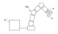
- 1 is a diagram showing a schematic configuration of a robot and a robot controller.
- the robot controller 10 is connected to the robot RB and controls the operation of the robot RB.
- the robot controller 10 controls the operation of the robot RB by outputting various parameters (operation command values) for controlling the operation of the robot RB to the robot RB.
- the robot control device 10 also has a function as a route generation device that generates a route for the robot RB. The detailed configuration of the robot controller 10 will be described later.
- the robot RB moves along a plurality of teaching points taught by a user or a plurality of waypoints generated from a route plan.
- the various operation command values include, for example, speed, acceleration, deceleration, and rotation angle of the joint of the robot RB.
- the robot hand H is attached to the tip as an end effector.
- the robot RB is, for example, a so-called pick-and-place robot that grips the work W, which is an operation target of the robot RB, at a predetermined position, and transports and places it to a predetermined destination.
- the robot RB has a tool attached as an end effector. In this case, the robot RB moves according to the taught route or the route based on the route plan, and performs predetermined processing such as welding, screwing, and inspection at a predetermined place.
- the configuration of the robot RB will be described.
- the robot RB is a vertical articulated robot
- the present invention is also applicable to horizontal articulated robots (scalar robots), parallel link robots, orthogonal robots, mobile robots, flying robots (drones), humanoid robots, and the like.
- FIG. 2 is a diagram showing a configuration of a robot which is a vertical articulated robot.
- the robot RB is a 6-degree-of-freedom 6-axis robot including a base link BL, links L1 to L6, and joints J1 to J6.
- the joint is a joint that connects the links.
- the joints J1 to J6 rotatably connect the links by a motor (not shown).
- a 6-axis robot is described as an example, but the number of axes is not limited to 6, and any number of 2 or more may be used. The number of links changes with the number of axes.
- the base link BL and the link L1 are connected via a joint J1 which rotates in the direction of arrow C1 about the vertical axis S1 in FIG. Therefore, the link L1 rotates in the direction of arrow C1 with the base link BL as a fulcrum.
- the link L1 and the link L2 are connected via a joint J2 that rotates in the direction of arrow C2 about the horizontal axis S2 in FIG. Therefore, the link L2 rotates in the arrow C2 direction with the joint J1 as a fulcrum.
- the link L2 and the link L3 are connected via a joint J3 that rotates in the direction of arrow C3 about the axis S3 in FIG. Therefore, the link L3 rotates in the direction of arrow C3 with the joint J2 as a fulcrum.
- the link L3 and the link L4 are connected via a joint J4 that rotates about the axis S4 in the direction of arrow C4 in FIG. Therefore, the link L4 rotates in the arrow C4 direction with the joint J3 as a fulcrum.
- the link L4 and the link L5 are connected via a joint J5 that rotates about the axis S5 in the direction of arrow C5 in FIG. Therefore, the link L5 rotates in the direction of arrow C5 with the joint J4 as a fulcrum.
- the link L5 and the link L6 are connected via a joint J6 which rotates about the axis S6 in the direction of arrow C6 in FIG. Therefore, the link L6 rotates in the direction of arrow C6 with the joint J5 as a fulcrum.
- the robot hand H is attached to the link L6.
- the joints J1 to J6 have their respective ranges of rotation angles set as movable ranges.
- the position of the hand of the robot RB or the posture of the robot RB is determined by the rotation angles of the joints J1 to J6. Therefore, when teaching the route to the robot RB, the angle values of the rotation angles of the joints J1 to J6 are expressed as a vector having a dimension corresponding to the number of axes of the robot (a 6-dimensional vector in the case of the present embodiment). Then, the vector is sequentially taught as a teaching point. In the case where the route is generated instead of being taught, similarly, the waypoints through which the robot RB passes are generated as a dimensional vector corresponding to the number of axes of the joints J1 to J6.
- vector data having coordinate values on the Cartesian coordinate system may be given as the motion path, instead of vector data having angle values at the teaching point or the waypoint.
- the coordinate values on the Cartesian coordinate system can be converted into the angle values of the joints J1 to J6 based on the inverse kinematics of the robot.
- FIG. 3 is a block diagram showing the hardware configuration of the robot controller 10.
- the robot controller 10 includes a CPU (Central Processing Unit) 11, a ROM (Read Only Memory) 12, a RAM (Random Access Memory) 13, a storage 14, an input unit 15, a monitor 16 and an optical disk drive device. 17 and a communication interface 18.
- the components are connected via a bus 19 so that they can communicate with each other.
- the ROM 12 or the storage 14 stores a robot control program for controlling the robot RB.
- the CPU 11 is a central processing unit and executes various programs and controls each component. That is, the CPU 11 reads the program from the ROM 12 or the storage 14 and executes the program using the RAM 13 as a work area.
- the CPU 11 controls the above-mentioned components and performs various arithmetic processes according to a program recorded in the ROM 12 or the storage 14.
- the ROM 12 stores various programs and various data.
- the RAM 13 temporarily stores a program or data as a work area.
- the storage 14 is configured by an HDD (Hard Disk Drive) or SSD (Solid State Drive), and stores various programs including an operating system and various data.
- the input unit 15 includes a keyboard 151 and a pointing device such as a mouse 152, and is used for performing various inputs.
- the monitor 16 is, for example, a liquid crystal display, and displays various kinds of information such as success or failure of suction of the work W.
- the monitor 16 may employ a touch panel method and function as the input unit 15.
- the optical disc driving device 17 reads data stored in various recording media (CD-ROM, Blu-ray disc, etc.) and writes data to the recording media.
- the communication interface 18 is an interface for communicating with other devices, and for example, a standard such as Ethernet (registered trademark), FDDI or Wi-Fi (registered trademark) is used.
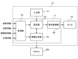
- FIG. 4 is a block diagram showing an example of the functional configuration of the robot controller 10.
- the robot control device 10 has an acquisition unit 20, a setting unit 22, a route generation unit 24, and a display control unit 26 as functional configurations.
- Each functional configuration is realized by the CPU 11 reading a robot control program stored in the ROM 12 or the storage 14, loading the robot control program in the RAM 13, and executing the program.
- the acquisition unit 20 acquires posture information, position information, obstacle information, and specification information. These pieces of information may be acquired by reading the information stored in the storage 14 in advance, or may be acquired from an external device.
- the posture information is information about the initial posture and the target posture of the robot RB.
- the position information is information on the position of the robot RB and includes, for example, coordinate values of the position of the robot RB in the three-dimensional space.
- the obstacle information is information including the position of an obstacle existing within a range where it interferes with the robot RB, that is, the position of a structure that becomes an obstacle in the operation of the robot RB, and for example, the coordinate value of the position of the obstacle in the three-dimensional space. including.
- the interference means contact with the robot RB.
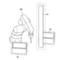
- the types of obstacles include a box 30 in which a work is accommodated, a shelf 32 on which the work is placed, a pedestal 34 on which the box 30 is installed, a pedestal 36 on which the shelf 32 is installed, and a camera for photographing the operation of the robot RB.
- the obstacle information includes, for example, three-dimensional shape data indicating the three-dimensional shape and size of the obstacle or the type of obstacle, in addition to the information on the position of the obstacle.
- the specification information is information about specifications including the shape of the robot RB.
- the specification information includes information indicating specifications such as the maximum speed, the maximum acceleration, the maximum deceleration, and the angular range that the rotation angle can take, in addition to the shapes of the joints J1 to J6 of the robot RB. ..
- the setting unit 22 avoids the interference between the robot RB and the obstacle with respect to at least one of the robot RB and the obstacle existing within the range where the robot RB interferes with the robot RB based on the positional relationship between the robot RB and the obstacle. Set the amount of clearance that represents the amount of clearance.
- the clearance amount may be set for the entire robot RB, or the clearance amount may be set individually for each of the joints J1 to J6. In the present embodiment, a case where a clearance amount is set individually for each joint will be described.
- the clearance amount may be set only for the robot RB, the clearance amount may be set only for the obstacle, or the clearance amount may be set for both the robot RB and the obstacle. Further, when there are a plurality of obstacles, the clearance amount may be set for all the obstacles, or the clearance amount may be set for only some of the obstacles.
- the route generation unit 24 generates route information regarding the route of the robot RB based on the initial posture and the target posture of the robot RB, the position of the robot RB, the position of the obstacle, the shape of the robot, and the clearance amount set by the setting unit 22. To generate.
- the route information is information about the route from the initial posture of the robot RB to the target posture and the speed at which the robot RB moves along the route.
- the path is a list of postures when the robot RB is moved from the initial posture to the target posture.
- the route is the rotation of each joint J1 to J6 at the teaching point or the passing point of the robot RB from the initial posture of the robot RB to the target posture. It is a list of angle values of angles.
- the information regarding the speed is, for example, a speed profile that represents a change in speed when the robot RB moves from the initial posture to the target posture.
- the speed of the robot RB is controlled according to the speed profile to move along the path.
- the display control unit 26 executes various display control processes such as displaying the robot RB and the obstacle for which the clearance amount is set on the monitor 16.
- FIG. 6 is a flowchart showing the flow of robot control processing by the robot control device 10.
- the CPU 11 reads out the robot control program from the ROM 12 or the storage 14, expands it in the RAM 13, and executes it to perform robot control processing.
- the robot control process includes a route generation process.
- the CPU 11 acquires the posture information of the robot RB, the position information of the robot RB, the obstacle information about the obstacle, and the specification information of the robot RB (step S100).
- the CPU 11 individually sets a clearance amount indicating the amount of clearance for avoiding the interference between the robot RB and the obstacle for at least one of the robot RB and the obstacle existing within the range in which the robot RB interferes (step S102).
- the clearance amount can be set individually by the user.
- the display control unit 26 causes the monitor RB to display the robot RB based on the specification information and causes the monitor 16 to display the obstacle based on the obstacle information.
- the user inputs the clearance amount to at least one of the joints and the obstacle of the robot RB by the input unit 15 based on the positional relationship between the robot RB and the obstacle. Accordingly, the clearance amount can be set for at least one of the robot RB and the obstacle.
- the clearance amount may be automatically set according to the clearance amount setting information 50 as shown in FIG. 7, for example.
- the clearance amount setting information 50 is table data representing the correspondence between the clearance setting target and the clearance amount.
- the clearance amount is set for each of the joints J1 to J6 in the robot RB.
- the clearance amount of the joints J1 to J3, which are the joints on the root side, is set to 10 mm. Setting the clearance amount of 10 mm in the joint J1 means that the thickness is increased by 10 mm in the normal direction to the surface of the joint J1.
- the clearance amount of joints J4 to J6, which are the joints on the hand side is set to 5 mm. That is, the clearance amount on the hand side is set smaller than the clearance amount on the joint on the root side.
- the joints J4 to J6 on the hand side may rush into the recessed portion of the recessed obstacle such as the box 30 or the shelf 32 in FIG. For this reason, if the clearance amount is set to a large value, for example, picking up a work existing in the corner of the box 30 may fail. For this reason, the clearance amount of the joints J4 to J6 on the hand side is made smaller than the clearance amount of the joints J1 to J3 on the base side. Further, as shown in FIG.
- the clearance amount of the camera stand 40 is set to 10 mm, while the clearance amount of the box 30 and the shelf 32 is set to 5 mm, which is smaller than that of the camera stand 40.
- the clearance amount setting information 50 has the clearance amount set based on the positional relationship between the robot RB and the obstacle. As a result, it is possible to prevent the success rate of picking up the work from decreasing.
- the route generation unit 24 determines from the initial posture to the target posture based on the posture information of the robot RB, the position information of the robot RB, the obstacle information about the obstacle, and the specification information of the robot RB acquired in step S100.
- the route information of the route is generated, and the simulation for operating the robot RB according to the generated route information is executed.
- the setting unit 22 may set the clearance amount for at least one of the robot RB and the obstacle according to the execution result of the simulation.
- a joint that projects into an obstacle having a recess such as the box 30 and the shelf 32 is specified, and the clearance amount of the joint that projects into the obstacle is smaller than the clearance amount of the joint that does not project into the obstacle.
- the clearance amount is set based on the positional relationship between the robot RB and the obstacle.
- the route information is generated by the same process as step S106 described below, the acceleration of the joint is calculated based on the generated route information, and when the calculated acceleration is equal to or greater than a predetermined threshold value, the acceleration is less than the predetermined threshold value.
- the clearance amount may be increased so that Thereby, the robot RB can be operated more safely.
- the velocity of the joint may be calculated instead of the acceleration, and the clearance amount may be set based on the calculated velocity.
- FIG. 8 shows a display example of an obstacle for which a clearance is set.
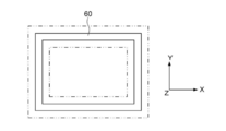
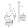
- clearances are individually set for the boxes 60, 62, and the support column 64, and a region where the clearances are set is indicated by a two-dot chain line.
- the clearance amount of the box 60 in which the work is accommodated and the box 62 in which the work is placed is smaller than the clearance amount of the column 64 which does not have the recess.
- the boxes 60 and 62 have a recess. Therefore, for example, not only is the clearance set outside the box 60 as shown in FIG. 9A when the box 60 is viewed from the side, but also inside the box 60 as shown in FIG. 9B when the box 60 is viewed from above. Clearance is also set.
- the obstacle may be displayed differently depending on the clearance amount.
- the clearance amount of the boxes 60 and 62 when the clearance amount of the boxes 60 and 62 is smaller than the clearance amount of the support column 64, the colors of the boxes 60 and 62 are different from the color of the support column 64. Thereby, it is possible to easily recognize that different clearance amounts are set.
- the clearance amount set for one obstacle may be set uniformly for other obstacles.
- the clearance amount set on the support column 64 may be set uniformly on the boxes 60 and 62.
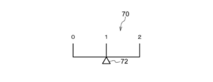
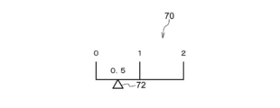
- the setting unit 22 may receive an adjustment coefficient for adjusting the clearance amount, and adjust a plurality of clearance amounts based on the received adjustment coefficient.
- a reception screen 70 that receives the adjustment coefficient is displayed on the monitor 16.
- the adjustment coefficient can be set in the range of 0 to 2 by performing an operation of sliding the adjustment bar 72 left and right.
- the range in which the adjustment coefficient can be set is not limited to this, and may be set as appropriate.
- the setting unit 22 sets a value obtained by multiplying the clearance amount by the adjustment coefficient as the adjusted clearance amount.
- the adjustment coefficient is set to “1”. Therefore, for example, when the clearance amount of the robot RB and the obstacle is set as shown in FIG. 7, each clearance amount does not change.
- the adjustment coefficient is set to “2”. Therefore, for example, the clearance amount of the box in FIG. 7 doubles to 10 mm, and the clearance amount of the camera stand doubles to 20 mm. Similarly, the other clearance amounts are doubled.
- the adjustment coefficient is set to “0.5”. Therefore, for example, the clearance amount of the box in FIG. 7 is 0.5 times 2.5 mm, and the clearance amount of the camera stand is 0.5 times 5 mm. The other clearance amounts are also 0.5 times.
- the CPU 11 uses the posture information, the position information, the obstacle information, and the specification information acquired in step S100, and the clearance amount set in step S102, and the route relating to the robot RB and the velocity-related route. Information is generated (step S106).
- RRT Rapidly exploring random tree
- RRT * Rapidly exploring random tree
- RRT connect PRM (Probabilistic Roadmap Method)
- STOMP Spochastic Trajectory Optimization for Motion Planninng
- CHOMP Covariant Hamiltonian Optimization for Motion Planning
- EET Exposure/Exploiting Tree
- the CPU 11 determines whether or not the robot RB interferes with the obstacle in the route generated in step S106 based on the route information generated in step S100 and the obstacle information ( Step S108).
- a known interference determination technique for determining the interference between the robot RB and the obstacle is used.
- a known interference determination technique for example, the technique described in JP-A-2002-273675 can be used.
- step S108 When it is determined that the robot RB does not interfere with the obstacle (step S108: NO), the process proceeds to step S110. On the other hand, when the robot RB interferes with the obstacle (step S108: YES), the process proceeds to step S106, and the route is regenerated so that the robot RB does not interfere with the obstacle. Then, the processes of steps S106 and S108 are repeated until the robot RB does not interfere with the obstacle.
- the CPU 11 determines whether or not the route generated in step S106 satisfies a predetermined route condition (step S110).
- the case where the route condition is satisfied is, for example, a case where the route length of the route is equal to or less than a predetermined reference route length.
- the path length is the length of the path from the initial posture generated in step S106 to the target posture.
- the reference route length may be, for example, a value obtained by adding a predetermined margin value to the route length of the route taught by teaching, or by adding a predetermined margin value to the route length of the route when the clearance is not set. It may be a value. This can prevent the path length from becoming too long.
- the route condition may be the case where the operation time of the route is less than or equal to a predetermined reference operation time.
- the operation time of the route is the time that the robot RB moves along the route from the initial posture generated in step S106 to the target posture.
- the reference operation time may be, for example, a value obtained by adding a predetermined margin value to the operation time of the route taught by teaching, or may be a value obtained by adding a predetermined margin value to the operation time of the route when the clearance is not set. It may be a value. This can prevent the operation time of the robot RB from becoming too long.
- the case where the route condition is satisfied may be the case where the route length of the route is equal to or less than the reference route length and the operation time of the route is equal to or less than the reference operation time.
- step S106 if the route generated in step S106 satisfies the predetermined route condition, the process proceeds to step S112. On the other hand, if the route generated in step S106 does not satisfy the predetermined route condition, the process proceeds to step S102 and the clearance amount is reset. That is, the clearance amount is reduced. Then, the processes of steps S102 to S110 are repeated until the generated route satisfies a predetermined route condition.
- step S112 the operation command value is output to the robot RB based on the generated route information.
- the robot RB operates according to the route information.
- the clearance amount is individually set for at least one of the robot RB and the obstacle. As a result, as compared with the case where the clearance amount is uniformly set, it is possible to prevent the success rate of the operation of the robot from decreasing and at the same time prevent the safety of the operation of the robot from decreasing.
- the obstacle information regarding the obstacles is generated based on the captured image captured by the camera 38 illustrated in FIG. 5, for example. You may.
- the camera 38 may be a camera that captures a two-dimensional image or a camera that captures a three-dimensional image.
- the acquisition unit 20 acquires a captured image captured by the camera 38.
- the setting unit 22 generates obstacle information based on the acquired captured image, and sets the clearance amount based on the generated obstacle information.
- a known method such as template matching can be used to generate the obstacle information.
- the clearance amount set in step S102 in FIG. 6 may be adjusted according to at least one of the weight and size of the work. For example, the clearance amount may be increased as the weight of the work increases, and the clearance amount may be decreased as the weight of the work decreases. Further, the clearance amount may increase as the size of the work increases, and the clearance amount may decrease as the size of the work decreases.
- the control target of the robot control device may be a robot that operates on simulation.
- the robot control processing executed by the CPU by reading the software (program) in each of the above embodiments may be executed by various processors other than the CPU.
- a processor a PLD (Programmable Logic Device) whose circuit configuration can be changed after manufacturing an FPGA (Field-Programmable Gate Array) or the like, and a specific processing of performing ASIC (Application Integrated Circuit), etc.
- An example is a dedicated electric circuit, which is a processor having a circuit configuration designed exclusively.
- the robot control process may be executed by one of these various processors, or a combination of two or more processors of the same type or different types (for example, a plurality of FPGAs and a combination of a CPU and an FPGA). Etc.).
- the hardware structure of these various processors is, more specifically, an electric circuit in which circuit elements such as semiconductor elements are combined.
- the mode in which the robot control program is stored (installed) in the storage 14 or the ROM 12 in advance has been described, but the present invention is not limited to this.
- the program may be provided in a recording medium such as CD-ROM (Compact Disk Read Only Memory), DVD-ROM (Digital Versatile Disk Read Only Memory), and USB (Universal Serial Bus) memory. Further, the program may be downloaded from an external device via a network.
- robot control device 20 acquisition unit 22 setting unit 24 route generation unit 26 display control units 30, 60, 62 box 32 shelf 38 camera 40 camera stand 50 clearance amount setting information 64 prop 70 reception screen 72 adjustment bar
Landscapes
- Engineering & Computer Science (AREA)
- Robotics (AREA)
- Mechanical Engineering (AREA)
- Human Computer Interaction (AREA)
- Manipulator (AREA)
- Numerical Control (AREA)
Abstract
経路生成装置は、ロボットの初期姿勢及び目標姿勢に関する姿勢情報、ロボットの位置に関する位置情報、ロボットと干渉する範囲内に存在する障害物の位置を含む障害物情報、及びロボットの形状を含む仕様に関する仕様情報を取得する取得部と、ロボットと障害物との位置関係に基づいて、ロボット及びロボットと干渉する範囲内に存在する障害物の少なくとも一方について、干渉を回避するためのクリアランスの量を表すクリアランス量を設定する設定部と、ロボットの初期姿勢及び目標姿勢、ロボットの位置、障害物の位置、ロボットの形状、及び設定部により設定されたクリアランス量に基づいてロボットの経路に関する経路情報を生成する経路生成部と、を備える。
Description
本発明は、経路生成装置、経路生成方法、及び経路生成プログラムに関する。
特許文献1には、ロボットの動作プログラムのシミュレーションを実行して、第1の動作経路を取得する動作経路取得部と、第1の動作経路における干渉を検出して、該干渉が発生する前後の教示点である第1の教示点及び第2の教示点を特定する教示点特定部と、第1及び第2の教示点の間に、乱数で定めた探索方向及び探索距離に基づき少なくとも1つの第3の教示点を自動的に挿入し、干渉が発生しない第2の動作経路を生成する動作経路生成部と、第2の動作経路の各々について、予め定めた少なくとも1つのパラメータに基づく評価を行う評価部と、該評価に基づいて、複数の第2の動作経路から最適動作経路を選択する動作経路選択部とを備えたロボットシミュレーション装置が開示されている。
ロボットが移動する経路を生成する際には、ロボットが障害物と干渉しないように、すなわちロボットと障害物との距離が安全な距離を保つように経路が生成される。従来、ロボットと障害物との安全な距離を表すクリアランス量は、ロボット又は障害物に対して一律で設定されていた。
クリアランス量がロボット又は障害物に対して一律に設定された場合、例えばピックアンドプレース装置において、安全性を高めるためにワークが収容される箱のクリアランス量が大きく設定されていると、箱の隅のワークのピッキングに失敗する確率が高まる。このため、全体のピッキングの成功率が低下する。一方、ピッキングの成功率を高めるためにクリアランス量を小さく設定すると安全性が低下してしまう。すなわち、ロボットが障害物と干渉するリスクが増加してしまう。
このように、ピッキング等のロボットの動作の成功率とロボットの動作の安全性とはトレードオフの関係にあり、両者を両立するのは困難であった。
本発明は、上記の点に鑑みてなされたものであり、ロボットの動作の成功率が低下するのを防ぎつつ、ロボットの動作の安全性が低下するのを防ぐことができる経路生成装置及び経路生成プログラムを提供することを目的とする。
開示の第1態様は、経路生成装置であって、ロボットの初期姿勢及び目標姿勢に関する姿勢情報、前記ロボットの位置に関する位置情報、前記ロボットと干渉する範囲内に存在する障害物の位置を含む障害物情報、及び前記ロボットの形状を含む仕様に関する仕様情報を取得する取得部と、前記ロボットと前記障害物との位置関係に基づいて、前記ロボット及び前記ロボットと干渉する範囲内に存在する障害物の少なくとも一方について、前記干渉を回避するためのクリアランスの量を表すクリアランス量を設定する設定部と、前記ロボットの初期姿勢及び目標姿勢、前記ロボットの位置、前記障害物の位置、前記ロボットの形状、及び前記設定部により設定されたクリアランス量に基づいて前記ロボットの経路に関する経路情報を生成する経路生成部と、を備える。
上記第1態様において、前記設定部は、前記経路生成部が生成した経路が予め定めた経路条件を満たさない場合は、前記クリアランス量を小さくし、前記経路生成部は、前記ロボットの初期姿勢及び目標姿勢と、前記ロボットの位置と、前記障害物の位置と、前記ロボットの形状と、前記設定部により設定されたクリアランス量と、に基づいて前記経路情報を再生成してもよい。
上記第1態様において、前記設定部は、前記障害物が凹みを有し且つ前記ロボットの操作対象であるワークが収容又は載置される障害物である場合、凹みを有さない障害物のクリアランス量よりも小さいクリアランス量を設定してもよい。
上記第1態様において、前記設定部は、前記経路情報に基づいて前記ロボットの関節の速度又は加速度を算出し、算出した前記ロボットの関節の速度又は加速度が予め定めた閾値以上の場合、前記速度又は加速度が予め定めた閾値未満となるように、前記クリアランス量を大きくするようにしてもよい。
上記第1態様において、前記設定部は、前記クリアランス量を調整する調整係数を受け付け、受け付けた調整係数に基づいて、複数の前記クリアランス量を調整するようにしてもよい。
上記第1態様において、前記クリアランス量に応じて前記障害物の表示が異なるように制御する表示制御部を備えた構成としてもよい。
開示の第2態様は、経路生成方法であって、コンピュータが、ロボットの初期姿勢及び目標姿勢に関する姿勢情報、前記ロボットの位置に関する位置情報、前記ロボットと干渉する範囲内に存在する障害物の位置を含む障害物情報、及びロボットの形状を含む仕様に関する仕様情報を取得する取得工程と、前記ロボットと前記障害物との位置関係に基づいて、前記ロボット及び前記ロボットと干渉する範囲内に存在する障害物の少なくとも一方について、前記干渉を回避するためのクリアランスの量を表すクリアランス量を設定する設定工程と、前記ロボットの初期姿勢及び目標姿勢、前記ロボットの位置、前記障害物の位置、前記ロボットの形状、及び前記設定工程により設定されたクリアランス量に基づいて前記ロボットの経路に関する経路情報を生成する経路生成工程と、を含む処理を実行する。
開示の第3態様は、経路生成プログラムであって、コンピュータを、ロボットの初期姿勢及び目標姿勢に関する姿勢情報、前記ロボットの位置に関する位置情報、前記ロボットと干渉する範囲内に存在する障害物の位置を含む障害物情報、及びロボットの形状を含む仕様に関する仕様情報を取得する取得部、前記ロボットと前記障害物との位置関係に基づいて、前記ロボット及び前記ロボットと干渉する範囲内に存在する障害物の少なくとも一方について、前記干渉を回避するためのクリアランスの量を表すクリアランス量を設定する設定部、及び、前記ロボットの初期姿勢及び目標姿勢、前記ロボットの位置、前記障害物の位置、前記ロボットの形状、及び前記設定部により設定されたクリアランス量に基づいて前記ロボットの経路に関する経路情報を生成する経路生成部、として機能させる。
本発明によれば、ロボットの動作の成功率が低下するのを防ぎつつ、ロボットの動作の安全性が低下するのを防ぐことができる。
以下、本発明の実施形態の一例を、図面を参照しつつ説明する。なお、各図面において同一又は等価な構成要素及び部分には同一の参照符号を付与している。また、図面の寸法比率は、説明の都合上誇張されている場合があり、実際の比率とは異なる場合がある。
図1は、ロボット及びロボット制御装置の概略構成を示す図である。
図1に示すように、ロボット制御装置10は、ロボットRBに接続され、ロボットRBの動作を制御する。ロボット制御装置10は、ロボットRBの動作を制御するための各種パラメータ(動作指令値)をロボットRBに出力することでロボットRBの動作を制御する。また、ロボット制御装置10は、ロボットRBの経路を生成する経路生成装置としての機能を有する。ロボット制御装置10の詳細な構成については後述する。
ロボットRBは、ユーザーにより教示される複数の教示点、又は、経路計画から生成された複数の経由点に沿って運動する。運動の際には、ロボットRBは、各種の動作指令値に従う。各種の動作指令値には、例えば、速度、加速度、減速度、ロボットRBの関節の回転角度等が含まれる。
ロボットRBは、一例として、先端にエンドエフェクタとしてロボットハンドHが取り付けられている。この場合、ロボットRBは、例えばロボットRBの操作対象であるワークWを所定の位置で把持し、所定の目的地まで搬送及び載置する、いわゆるピックアンドプレースロボットである。他の例として、ロボットRBは、エンドエフェクタとして工具が取り付けられている。この場合、ロボットRBは、教示された経路又は経路計画に基づく経路に従って移動し、所定の場所で、溶接、ねじ止め、検査等の所定の処理を行う。
ロボット制御装置10の詳細について説明する前に、ロボットRBの構成について説明する。本実施形態では、一例としてロボットRBが垂直多関節ロボットである場合について説明する。しかし、水平多関節ロボット(スカラーロボット)、パラレルリンクロボット、直交ロボット、モバイルロボット、飛行ロボット(ドローン)、及びヒューマノイド型ロボット等にも本発明は適用可能である。
図2は、垂直多関節ロボットであるロボットの構成を示す図である。
図2に示すように、ロボットRBは、ベースリンクBL、リンクL1~L6、ジョイントJ1~J6を備えた6自由度の6軸ロボットである。なお、ジョイントとは、リンク同士を接続する関節である。ジョイントJ1~J6は、図示しないモータによりリンク同士を回転可能に接続する。本実施形態では、6軸ロボットを例に説明するが、軸の数は6に限定されず、2以上のいかなる数であっても良い。軸の数に伴い、リンクの数も変わる。
ベースリンクBLとリンクL1とは、図2において鉛直軸S1を中心として矢印C1方向に回転するジョイントJ1を介して接続されている。従って、リンクL1は、ベースリンクBLを支点として矢印C1方向に回転する。
リンクL1とリンクL2とは、図2において水平軸S2を中心として矢印C2方向に回転するジョイントJ2を介して接続されている。従って、リンクL2は、ジョイントJ1を支点として矢印C2方向に回転する。
リンクL2とリンクL3とは、図2において軸S3を中心として矢印C3方向に回転するジョイントJ3を介して接続されている。従って、リンクL3は、ジョイントJ2を支点として矢印C3方向に回転する。
リンクL3とリンクL4とは、図2において軸S4を中心として矢印C4方向に回転するジョイントJ4を介して接続されている。従って、リンクL4は、ジョイントJ3を支点として矢印C4方向に回転する。
リンクL4とリンクL5とは、図2において軸S5を中心として矢印C5方向に回転するジョイントJ5を介して接続されている。従って、リンクL5は、ジョイントJ4を支点として矢印C5方向に回転する。
リンクL5とリンクL6とは、図2において軸S6を中心として矢印C6方向に回転するジョイントJ6を介して接続されている。従って、リンクL6は、ジョイントJ5を支点として矢印C6方向に回転する。なお、図2では図示は省略したが、リンクL6にロボットハンドHが取り付けられる。
ジョイントJ1~J6は、予め定めた回転角度の範囲が可動域として各々設定されている。
ロボットRBの手先の位置又はロボットRBの姿勢は、各ジョイントJ1~J6の各々の回転角度によって定まる。従って、ロボットRBに経路を教示する場合には、各ジョイントJ1~J6の回転角度の角度値を、ロボットの持つ軸数分の次元のベクトル(本実施形態の場合は6次元のベクトル)として表現し、当該ベクトルを、教示点として順に教示する。経路を教示するのではなく生成する場合についても、同様に、ロボットRBが通過する経由点が、各ジョイントJ1~J6の軸数分の次元のベクトルとして生成される。なお、動作経路として、教示点又は経由点における各角度値を持つベクトルデータではなく、直交座標系上での各座標値を持つベクトルデータが与えられる場合もある。この場合、直交座標系上の座標値は、ロボットの逆運動学に基づいて、ジョイントJ1~J6の角度値に変換可能である。
次に、ロボット制御装置10について説明する。
図3は、ロボット制御装置10のハードウェア構成を示すブロック図である。
図3に示すように、ロボット制御装置10は、CPU(Central Processing Unit)11、ROM(Read Only Memory)12、RAM(Random Access Memory)13、ストレージ14、入力部15、モニタ16、光ディスク駆動装置17及び通信インタフェース18を有する。各構成は、バス19を介して相互に通信可能に接続されている。
本実施形態では、ROM12又はストレージ14には、ロボットRBを制御するロボット制御プログラムが格納されている。CPU11は、中央演算処理ユニットであり、各種プログラムを実行したり、各構成を制御したりする。すなわち、CPU11は、ROM12又はストレージ14からプログラムを読み出し、RAM13を作業領域としてプログラムを実行する。CPU11は、ROM12又はストレージ14に記録されているプログラムに従って、上記各構成の制御及び各種の演算処理を行う。
ROM12は、各種プログラム及び各種データを格納する。RAM13は、作業領域として一時的にプログラム又はデータを記憶する。ストレージ14は、HDD(Hard Disk Drive)又はSSD(Solid State Drive)により構成され、オペレーティングシステムを含む各種プログラム、及び各種データを格納する。
入力部15は、キーボード151、及びマウス152等のポインティングデバイスを含み、各種の入力を行うために使用される。モニタ16は、例えば、液晶ディスプレイであり、ワークWの吸着の成否等の各種の情報を表示する。モニタ16は、タッチパネル方式を採用して、入力部15として機能してもよい。光ディスク駆動装置17は、各種の記録媒体(CD-ROM又はブルーレイディスクなど)に記憶されたデータの読み込みや、記録媒体に対するデータの書き込み等を行う。
通信インタフェース18は、他の機器と通信するためのインタフェースであり、例えば、イーサネット(登録商標)、FDDI又はWi-Fi(登録商標)等の規格が用いられる。
次に、ロボット制御装置10の機能構成について説明する。
図4は、ロボット制御装置10の機能構成の例を示すブロック図である。
図4に示すように、ロボット制御装置10は、機能構成として、取得部20、設定部22、経路生成部24、及び表示制御部26を有する。各機能構成は、CPU11がROM12又はストレージ14に記憶されたロボット制御プログラムを読み出し、RAM13に展開して実行することにより実現される。
取得部20は、姿勢情報、位置情報、障害物情報、及び仕様情報を取得する。これらの情報は、予めストレージ14に記憶されている情報を読み出すことにより取得してもよいし、外部装置から取得してもよい。
姿勢情報は、ロボットRBの初期姿勢及び目標姿勢に関する情報である。
位置情報は、ロボットRBの位置に関する情報であり、例えばロボットRBの3次元空間上の位置の座標値を含む。
障害物情報は、ロボットRBと干渉する範囲内に存在する障害物、すなわちロボットRBの動作において障害となる構造物の位置を含む情報であり、例えば障害物の3次元空間上の位置の座標値を含む。ここで、干渉とは、ロボットRBと接触することをいう。本実施形態では、例えば図5に示すように、ロボット制御装置10がピックアンドプレース装置に適用される場合について説明する。障害物の種類としては、ワークが収容される箱30、ワークが載置される棚32、箱30が設置される台座34、棚32が設置される台座36、ロボットRBの動作を撮影するカメラ38、及びカメラ38が取り付けられたカメラスタンド40等が挙げられる。また、本実施形態では、障害物情報は、障害物の位置に関する情報の他に、例えば障害物の三次元形状及び大きさを表す三次元形状データ又は障害物の種類を含む。
仕様情報は、ロボットRBの形状を含む仕様に関する情報である。本実施形態では一例として、仕様情報は、ロボットRBの各ジョイントJ1~J6の形状の他に、最大速度、最大加速度、最大減速度、回転角度が取り得る角度範囲等の仕様を表す情報を含む。
設定部22は、ロボットRBと障害物との位置関係に基づいて、ロボットRB及びロボットRBと干渉する範囲内に存在する障害物の少なくとも一方について、ロボットRBと障害物との干渉を回避するためのクリアランスの量を表すクリアランス量を設定する。
なお、ロボットRB全体にクリアランス量を設定してもよいし、ジョイントJ1~J6の各ジョイントについて個別にクリアランス量を設定してもよい。本実施形態では、各ジョイントについて個別にクリアランス量を設定する場合について説明する。
また、ロボットRBのみにクリアランス量を設定してもよいし、障害物のみにクリアランス量を設定してもよいし、ロボットRB及び障害物の両方にクリアランス量を設定してもよい。また、複数の障害物が存在する場合は、全ての障害物にクリアランス量を設定してもよいし、一部の障害物のみにクリアランス量を設定してもよい。
経路生成部24は、ロボットRBの初期姿勢及び目標姿勢、ロボットRBの位置、障害物の位置、ロボットの形状、及び設定部22により設定されたクリアランス量に基づいてロボットRBの経路に関する経路情報を生成する。経路情報は、ロボットRBの初期姿勢から目標姿勢までの経路及びロボットRBが経路を移動する際の速度に関する情報である。ここで、経路とは、ロボットRBを初期姿勢から目標姿勢まで動作させる場合の姿勢のリストである。ロボットRBの姿勢は、各ジョイントJ1~J6の回転角度の角度値で定まるため、経路は、ロボットRBの初期姿勢から目標姿勢までのロボットRBの教示点又は経由点の各ジョイントJ1~J6の回転角度の角度値のリストである。
また、速度に関する情報は、例えばロボットRBが初期姿勢から目標姿勢まで動作する場合の速度の変化を表す速度プロファイルである。ロボットRBは、速度プロファイルに従って速度が制御されて経路を移動する。
表示制御部26は、クリアランス量が設定されたロボットRB及び障害物をモニタ16に表示させたりする等、各種の表示制御処理を実行する。
次に、ロボット制御装置10の作用について説明する。
図6は、ロボット制御装置10によるロボット制御処理の流れを示すフローチャートである。CPU11がROM12又はストレージ14からロボット制御プログラムを読み出して、RAM13に展開し実行することにより、ロボット制御処理が行なわれる。なお、ロボット制御処理には、経路生成処理が含まれる。
CPU11は、取得部20として、ロボットRBの姿勢情報、ロボットRBの位置情報、障害物に関する障害物情報、及びロボットRBの仕様情報を取得する(ステップS100)。
CPU11は、ロボットRB及びロボットRBと干渉する範囲内に存在する障害物の少なくとも一方について、ロボットRBと障害物との干渉を回避するためのクリアランスの量を表すクリアランス量を個別に設定する(ステップS102)。
以下、クリアランス量の設定方法について説明する。
まず、例えばユーザーによってクリアランス量を個別に設定することができる。この場合、例えば表示制御部26が、仕様情報に基づいてロボットRBをモニタ16に表示させると共に、障害物情報に基づいて障害物をモニタ16に表示させる。そして、ユーザーが、入力部15によりロボットRBの各ジョイント及び障害物の少なくとも一方に対して、ロボットRBと障害物との位置関係に基づいてクリアランス量を入力する。これにより、ロボットRB及び障害物の少なくとも一方に対してクリアランス量を設定できる。
また、例えば図7に示すようなクリアランス量設定情報50に従ってクリアランス量を自動で設定してもよい。図7に示すように、クリアランス量設定情報50は、クリアランスの設定対象とクリアランス量との対応関係を表すテーブルデータである。図7に示すように、クリアランス量は、ロボットRBであればジョイントJ1~J6の各々に対して設定されている。ここで、根元側のジョイントであるジョイントJ1~J3のクリアランス量は10mmに設定されている。なお、ジョイントJ1にクリアランス量10mmを設定するということは、ジョイントJ1の表面に対して法線方向に10mm分厚みが増すことを意味する。
一方、手先側のジョイントであるジョイントJ4~J6のクリアランス量は5mmに設定されている。すなわち、根元側のジョイントのクリアランス量よりも手先側のクリアランス量が小さく設定されている。手先側のジョイントJ4~J6は、図5の箱30又は棚32のように凹みのある障害物の凹み部分に突入する可能性がある。このため、クリアランス量を大きめに設定してしまうと、例えば箱30の隅に存在するワークのピックアップを失敗する場合がある。このため、手先側のジョイントJ4~J6のクリアランス量を根元側のジョイントJ1~J3のクリアランス量よりも小さくしている。また、図7に示すように、カメラスタンド40のクリアランス量が10mmに設定されているのに対し、箱30及び棚32のクリアランス量はカメラスタンド40よりも小さい5mmに設定されている。このように、クリアランス量設定情報50は、ロボットRBと障害物との位置関係に基づいてクリアランス量が設定されている。これにより、ワークのピックアップの成功率が低下するのを防ぐことができる。
次に、他のクリアランス量の設定方法について説明する。まず、例えば経路生成部24が、ステップS100で取得したロボットRBの姿勢情報、ロボットRBの位置情報、障害物に関する障害物情報、及びロボットRBの仕様情報に基づいて、初期姿勢から目標姿勢までの経路の経路情報を生成し、生成した経路情報に従ってロボットRBを動作させるシミュレーションを実行する。そして、設定部22が、シミュレーションの実行結果に従ってロボットRB及び障害物の少なくとも一方にクリアランス量を設定してもよい。具体的には、例えば箱30及び棚32のように凹みを有する障害物に突入するジョイントを特定し、障害物に突入するジョイントのクリアランス量を、障害物に突入しないジョイントのクリアランス量よりも小さく設定する。すなわち、ロボットRBと障害物との位置関係に基づいてクリアランス量を設定する。また、後述するステップS106と同様の処理により経路情報を生成し、生成した経路情報に基づいてジョイントの加速度を算出し、算出した加速度が予め定めた閾値以上の場合、加速度が予め定めた閾値未満となるように、クリアランス量を大きくしてもよい。これにより、より安全にロボットRBを動作させることができる。なお、加速度に代えてジョイントの速度を算出し、算出した速度に基づいてクリアランス量を設定してもよい。
CPU11は、表示制御部26として、ステップS100で取得した仕様情報及び障害物情報に基づいて、ロボットRB及び障害物をモニタ16に表示する(ステップS104)。このとき、ステップS102で設定されたクリアランス量でクリアランスが設定されていることが認識できるように表示する。図8には、クリアランスが設定された障害物の表示例を示した。図8の例では、箱60、62、支柱64の各々に対して個別にクリアランスが設定されており、クリアランスが設定された領域を2点鎖線で示している。図8の例では、凹みを有し、ワークが収容される箱60、ワークが載置される箱62のクリアランス量が、凹みを有さない支柱64のクリアランス量よりも小さくなっている。なお、箱60、62は凹みを有する。このため、例えば箱60を側面から見た図9Aに示すように、箱60の外側にクリアランスが設定されるだけでなく、箱60を上側から見た図9Bに示すように、箱60の内側にもクリアランスが設定される。
なお、クリアランス量に応じて障害物の表示が異なるように制御するようにしてもよい。例えば図10に示すように、箱60、62のクリアランス量が、支柱64のクリアランス量よりも小さい場合は、箱60、62の色と、支柱64の色と、を異ならせる。これにより、異なるクリアランス量が設定されていることを容易に認識できる。
また、1つの障害物に設定したクリアランス量を他の障害物に一律に設定するようにしてもよい。例えば図11に示すように、支柱64に設定したクリアランス量を箱60、62に一律に設定するようにしてもよい。
また、設定部22が、クリアランス量を調整する調整係数を受け付け、受け付けた調整係数に基づいて、複数のクリアランス量を調整するようにしてもよい。例えば図12Aに示すように、調整係数を受け付ける受付画面70をモニタ16に表示する。図12Aの例では、調整バー72を左右にスライドさせる操作を行うことにより、調整係数を0~2の範囲で設定可能である。なお、調整係数の設定可能な範囲はこれに限られるものではなく、適宜設定すればよい。設定部22は、調整係数を受け付けた場合、クリアランス量に調整係数を乗算した値を調整後のクリアランス量として設定する。
例えば図12Aでは、調整係数は「1」に設定されている。このため、例えば図7に示すようにロボットRB及び障害物のクリアランス量が設定されていた場合、各クリアランス量は変化しない。
また、図12Bでは、調整係数は「2」に設定されている。このため、例えば図7の箱のクリアランス量は2倍の10mmとなり、カメラスタンドのクリアランス量も2倍の20mmとなる。その他のクリアランス量についても同様に2倍となる。
また、図12Cでは、調整係数は「0.5」に設定されている。このため、例えば図7の箱のクリアランス量は0.5倍の2.5mmとなり、カメラスタンドのクリアランス量も0.5倍の5mmとなる。その他のクリアランス量についても同様に0.5倍となる。
このように、調整係数を設定することで複数のクリアランス量を調整することができる。
CPU11は、経路生成部24として、ステップS100で取得した姿勢情報、位置情報、障害物情報、及び仕様情報と、ステップS102で設定されたクリアランス量と、に基づいてロボットRBの経路及び速度に関する経路情報を生成する(ステップS106)。
経路情報の生成方法としては種々公知の方法を採用することができる。例えば、経路の生成方法としては、RRT(Rapidly exploring random tree)、RRT*、RRT connect、PRM(Probabilistic Roadmap Method)、STOMP(Stochastic Trajectory Optimization for Motion Planninng)、CHOMP(Covariant Hamiltonian Optimization for Motion Planning)、EET(Exploring/Exploiting Tree)等が挙げられる。
CPU11は、経路生成部24として、ステップS100で生成した経路情報と、障害物情報と、に基づいて、ステップS106で生成した経路において、ロボットRBが障害物と干渉するか否かを判定する(ステップS108)。干渉の判定には、例えばロボットRBと障害物との干渉を判定する公知の干渉判定技術を用いる。公知の干渉判定技術としては、例えば特開2002-273675号公報に記載の技術を用いることができる。
そして、ロボットRBが障害物と干渉しないと判定した場合(ステップS108:NO)は、ステップS110へ移行する。一方、ロボットRBが障害物に干渉する場合(ステップS108:YES)、ステップS106へ移行し、ロボットRBが障害物と干渉しないように経路を再生成する。そして、ロボットRBが障害物と干渉しなくなるまでステップS106、S108の処理を繰り返す。
CPU11は、経路生成部24として、ステップS106で生成した経路が予め定めた経路条件を満たすか否かを判定する(ステップS110)。経路条件を満たす場合とは、例えば経路の経路長が予め定めた基準経路長以下の場合である。ここで、経路長とは、ステップS106で生成した初期姿勢から目標姿勢までの経路の長さである。また、基準経路長は、例えばティーチングにより教示した経路の経路長に予め定めたマージン値を加算した値としてもよいし、クリアランスを設定しない場合の経路の経路長に予め定めたマージン値を加算した値としてもよい。これにより、経路長が長くなり過ぎるのを防ぐことができる。
なお、経路条件を満たす場合を、経路の動作時間が予め定めた基準動作時間以下の場合としてもよい。ここで、経路の動作時間とは、ステップS106で生成した初期姿勢から目標姿勢までの経路をロボットRBが移動する時間である。また、基準動作時間は、例えばティーチングにより教示した経路の動作時間に予め定めたマージン値を加算した値としてもよいし、クリアランスを設定しない場合の経路の動作時間に予め定めたマージン値を加算した値としてもよい。これにより、ロボットRBの動作時間が長くなり過ぎるのを防ぐことができる。
また、経路条件を満たす場合を、経路の経路長が基準経路長以下で且つ経路の動作時間が基準動作時間以下の場合としてもよい。
そして、ステップS106で生成した経路が予め定めた経路条件を満たす場合は、ステップS112へ移行する。一方、ステップS106で生成した経路が予め定めた経路条件を満たさない場合は、ステップS102へ移行し、クリアランス量を再設定する。すなわち、クリアランス量を小さくする。そして、生成した経路が予め定めた経路条件を満たすまでステップS102~S110の処理を繰り返す。
ステップS112では、生成した経路情報に基づいて動作指令値をロボットRBに出力する。これにより、ロボットRBが経路情報に従って動作する。
このように、本実施形態では、ロボットRB及び障害物の少なくとも一方について、クリアランス量が個別に設定される。これにより、クリアランス量が一律に設定される場合と比較して、ロボットの動作の成功率が低下するのを防ぎつつ、ロボットの動作の安全性が低下するのを防ぐことができる。
なお、本実施形態では、障害物情報を取得する場合について説明したが、例えば図5に示すカメラ38により撮影された撮影画像に基づいて箱30、棚32等の障害物に関する障害物情報を生成してもよい。この場合、カメラ38は、二次元画像を撮影するカメラでもよいし、三次元画像を撮影するカメラでもよい。
取得部20は、カメラ38で撮影された撮影画像を取得する。設定部22は、取得した撮影画像に基づいて障害物情報を生成し、生成した障害物情報に基づいてクリアランス量を設定する。障害物情報の生成には、公知のテンプレートマッチング等の手法を用いることができる。
このように、カメラ38により撮影された撮影画像に基づいて生成した障害物情報に基づいてクリアランス量を設定することにより、障害物情報を予め用意しておく必要がない。
また、図6のステップS102で設定されたクリアランス量について、ワークの重さ及びサイズの少なくとも一方に応じてクリアランス量を調整するようにしてもよい。例えば、ワークの重さが重くなるに従ってクリアランス量が大きくなり、ワークの重さが軽くなるに従ってクリアランス量が小さくなるように調整してもよい。また、ワークのサイズが大きくなるに従ってクリアランス量が大きくなり、ワークのサイズが小さくなるに従ってクリアランス量が小さくなるように設定してもよい。
また、本実施形態では、ロボット制御装置の制御対象であるロボットRBが実機の場合について説明したが、ロボット制御装置の制御対象が、シミュレーション上で動作するロボットであってもよい。
なお、上記各実施形態でCPUがソフトウェア(プログラム)を読み込んで実行したロボット制御処理を、CPU以外の各種のプロセッサが実行してもよい。この場合のプロセッサとしては、FPGA(Field-Programmable Gate Array)等の製造後に回路構成を変更可能なPLD(Programmable Logic Device)、及びASIC(Application Specific Integrated Circuit)等の特定の処理を実行させるために専用に設計された回路構成を有するプロセッサである専用電気回路等が例示される。また、ロボット制御処理を、これらの各種のプロセッサのうちの1つで実行してもよいし、同種又は異種の2つ以上のプロセッサの組み合わせ(例えば、複数のFPGA、及びCPUとFPGAとの組み合わせ等)で実行してもよい。また、これらの各種のプロセッサのハードウェア的な構造は、より具体的には、半導体素子等の回路素子を組み合わせた電気回路である。
また、上記各実施形態では、ロボット制御プログラムがストレージ14又はROM12に予め記憶(インストール)されている態様を説明したが、これに限定されない。プログラムは、CD-ROM(Compact Disk Read Only Memory)、DVD-ROM(Digital Versatile Disk Read Only Memory)、及びUSB(Universal Serial Bus)メモリ等の記録媒体に記録された形態で提供されてもよい。また、プログラムは、ネットワークを介して外部装置からダウンロードされる形態としてもよい。
10 ロボット制御装置
20 取得部
22 設定部
24 経路生成部
26 表示制御部
30、60、62 箱
32 棚
38 カメラ
40 カメラスタンド
50 クリアランス量設定情報
64 支柱
70 受付画面
72 調整バー
20 取得部
22 設定部
24 経路生成部
26 表示制御部
30、60、62 箱
32 棚
38 カメラ
40 カメラスタンド
50 クリアランス量設定情報
64 支柱
70 受付画面
72 調整バー
Claims (8)
- ロボットの初期姿勢及び目標姿勢に関する姿勢情報、前記ロボットの位置に関する位置情報、前記ロボットと干渉する範囲内に存在する障害物の位置を含む障害物情報、及び前記ロボットの形状を含む仕様に関する仕様情報を取得する取得部と、
前記ロボットと前記障害物との位置関係に基づいて、前記ロボット及び前記ロボットと干渉する範囲内に存在する障害物の少なくとも一方について、前記干渉を回避するためのクリアランスの量を表すクリアランス量を設定する設定部と、
前記ロボットの初期姿勢及び目標姿勢、前記ロボットの位置、前記障害物の位置、前記ロボットの形状、及び前記設定部により設定されたクリアランス量に基づいて前記ロボットの経路に関する経路情報を生成する経路生成部と、
を備えた経路生成装置。 - 前記設定部は、前記経路生成部が生成した経路が予め定めた経路条件を満たさない場合は、前記クリアランス量を小さくし、
前記経路生成部は、前記ロボットの初期姿勢及び目標姿勢と、前記ロボットの位置と、前記障害物の位置と、前記ロボットの形状と、前記設定部により設定されたクリアランス量と、に基づいて前記経路情報を再生成する
請求項1記載の経路生成装置。 - 前記設定部は、前記障害物が凹みを有し且つ前記ロボットの操作対象であるワークが収容又は載置される障害物である場合、凹みを有さない障害物のクリアランス量よりも小さいクリアランス量を設定する
請求項1又は請求項2記載の経路生成装置。 - 前記設定部は、前記経路情報に基づいて前記ロボットの関節の速度又は加速度を算出し、算出した前記ロボットの関節の速度又は加速度が予め定めた閾値以上の場合、前記速度又は加速度が予め定めた閾値未満となるように、前記クリアランス量を大きくする
請求項1~3の何れか1項に記載の経路生成装置。 - 前記設定部は、前記クリアランス量を調整する調整係数を受け付け、受け付けた調整係数に基づいて、複数の前記クリアランス量を調整する
請求項1~4の何れか1項に記載の経路生成装置。 - 前記クリアランス量に応じて前記障害物の表示が異なるように制御する表示制御部
を備えた請求項1~5の何れか1項に記載の経路生成装置。 - コンピュータが、
ロボットの初期姿勢及び目標姿勢に関する姿勢情報、前記ロボットの位置に関する位置情報、前記ロボットと干渉する範囲内に存在する障害物の位置を含む障害物情報、及びロボットの形状を含む仕様に関する仕様情報を取得する取得工程と、
前記ロボットと前記障害物との位置関係に基づいて、前記ロボット及び前記ロボットと干渉する範囲内に存在する障害物の少なくとも一方について、前記干渉を回避するためのクリアランスの量を表すクリアランス量を設定する設定工程と、
前記ロボットの初期姿勢及び目標姿勢、前記ロボットの位置、前記障害物の位置、前記ロボットの形状、及び前記設定工程により設定されたクリアランス量に基づいて前記ロボットの経路に関する経路情報を生成する経路生成工程と、
を含む処理を実行する経路生成方法。 - コンピュータを、
ロボットの初期姿勢及び目標姿勢に関する姿勢情報、前記ロボットの位置に関する位置情報、前記ロボットと干渉する範囲内に存在する障害物の位置を含む障害物情報、及びロボットの形状を含む仕様に関する仕様情報を取得する取得部、
前記ロボットと前記障害物との位置関係に基づいて、前記ロボット及び前記ロボットと干渉する範囲内に存在する障害物の少なくとも一方について、前記干渉を回避するためのクリアランスの量を表すクリアランス量を設定する設定部、及び、
前記ロボットの初期姿勢及び目標姿勢、前記ロボットの位置、前記障害物の位置、前記ロボットの形状、及び前記設定部により設定されたクリアランス量に基づいて前記ロボットの経路に関する経路情報を生成する経路生成部、
として機能させる経路生成プログラム。
Priority Applications (3)
| Application Number | Priority Date | Filing Date | Title |
|---|---|---|---|
| EP19910467.0A EP3912768A4 (en) | 2019-01-15 | 2019-11-27 | ROUTE GENERATOR, ROUTE GENERATION METHOD AND ROUTE GENERATION PROGRAM |
| US17/275,315 US12090666B2 (en) | 2019-01-15 | 2019-11-27 | Path generation device, path generation method, and recording medium storing path generation program |
| CN201980059699.XA CN112672857B (zh) | 2019-01-15 | 2019-11-27 | 路径生成装置、路径生成方法及存储有路径生成程序的存储介质 |
Applications Claiming Priority (2)
| Application Number | Priority Date | Filing Date | Title |
|---|---|---|---|
| JP2019-004311 | 2019-01-15 | ||
| JP2019004311A JP7147571B2 (ja) | 2019-01-15 | 2019-01-15 | 経路生成装置、経路生成方法、及び経路生成プログラム |
Publications (1)
| Publication Number | Publication Date |
|---|---|
| WO2020149021A1 true WO2020149021A1 (ja) | 2020-07-23 |
Family
ID=71614212
Family Applications (1)
| Application Number | Title | Priority Date | Filing Date |
|---|---|---|---|
| PCT/JP2019/046326 Ceased WO2020149021A1 (ja) | 2019-01-15 | 2019-11-27 | 経路生成装置、経路生成方法、及び経路生成プログラム |
Country Status (5)
| Country | Link |
|---|---|
| US (1) | US12090666B2 (ja) |
| EP (1) | EP3912768A4 (ja) |
| JP (1) | JP7147571B2 (ja) |
| CN (1) | CN112672857B (ja) |
| WO (1) | WO2020149021A1 (ja) |
Cited By (2)
| Publication number | Priority date | Publication date | Assignee | Title |
|---|---|---|---|---|
| CN113568435A (zh) * | 2021-09-24 | 2021-10-29 | 深圳火眼智能有限公司 | 一种基于无人机自主飞行态势感知趋势的分析方法与系统 |
| WO2023162164A1 (ja) * | 2022-02-25 | 2023-08-31 | 三菱電機株式会社 | 教示支援装置、作業システム、教示支援方法および教示支援プログラム |
Families Citing this family (10)
| Publication number | Priority date | Publication date | Assignee | Title |
|---|---|---|---|---|
| WO2020161910A1 (ja) * | 2019-02-08 | 2020-08-13 | 日本電気株式会社 | 制御装置、制御方法、記録媒体 |
| TWI873149B (zh) | 2019-06-24 | 2025-02-21 | 美商即時機器人股份有限公司 | 用於多個機械手臂於共用工作空間中之移動規劃系統及方法 |
| WO2022119934A1 (en) * | 2020-12-02 | 2022-06-09 | Realtime Robotics, Inc. | Systems, methods, and user interfaces employing clearance determinations in robot motion planning and control |
| JP7637564B2 (ja) * | 2021-05-27 | 2025-02-28 | 株式会社ジャノメ | 経路教示データ作成装置及び経路教示データ作成方法並びにプログラム |
| CN113448667B (zh) * | 2021-06-09 | 2023-08-01 | 绿盟科技集团股份有限公司 | 一种生成展示关系图的方法及装置 |
| CN114952863B (zh) * | 2022-06-30 | 2025-09-19 | 中船黄埔文冲船舶有限公司 | 一种中组立分段焊缝机器人的回避障碍控制方法及装置 |
| US12600035B2 (en) | 2022-07-05 | 2026-04-14 | Canon Kabushiki Kaisha | Information processing method, information processing apparatus, robot system, manufacturing method of product, and storage medium |
| JP7831219B2 (ja) | 2022-10-06 | 2026-03-17 | 株式会社デンソー | 干渉判定装置及び経路生成装置 |
| CN116038688B (zh) * | 2022-11-14 | 2024-12-20 | 上海理工大学 | 基于概率虚拟势场引导双向rrt*算法的机械臂关节空间路径规划方法 |
| WO2026003551A1 (en) * | 2024-06-24 | 2026-01-02 | Abb Schweiz Ag | System and method for dynamically assigning collision clearance distances for motion of a robot |
Citations (12)
| Publication number | Priority date | Publication date | Assignee | Title |
|---|---|---|---|---|
| JPH05204428A (ja) * | 1992-01-28 | 1993-08-13 | Fanuc Ltd | 複数ロボット制御方式 |
| JPH05250023A (ja) * | 1991-10-23 | 1993-09-28 | Sanyo Electric Co Ltd | ロボットマニピュレータの経路自動生成法 |
| JPH0934524A (ja) * | 1995-07-18 | 1997-02-07 | Kobe Steel Ltd | ロボットマニピュレータの移動経路の自動生成方法 |
| JP2002273675A (ja) | 2001-03-16 | 2002-09-25 | Kawasaki Heavy Ind Ltd | ロボット制御方法およびロボット制御システム |
| JP2003280710A (ja) * | 2002-03-20 | 2003-10-02 | Japan Atom Energy Res Inst | ロボットハンドの作業軌道の生成と制御方法 |
| JP2007313592A (ja) * | 2006-05-24 | 2007-12-06 | Toyota Motor Corp | 経路作成装置及び経路作成方法 |
| JP2009032189A (ja) * | 2007-07-30 | 2009-02-12 | Toyota Motor Corp | ロボットの動作経路生成装置 |
| JP2009233757A (ja) * | 2008-03-25 | 2009-10-15 | Ihi Corp | ロボット装置の制御方法及びロボット装置 |
| JP2015160277A (ja) | 2014-02-27 | 2015-09-07 | ファナック株式会社 | ロボットの動作経路を生成するロボットシミュレーション装置 |
| JP2016078184A (ja) * | 2014-10-17 | 2016-05-16 | ファナック株式会社 | ロボットの干渉領域設定装置 |
| JP2018134703A (ja) * | 2017-02-21 | 2018-08-30 | 株式会社安川電機 | ロボットシミュレータ、ロボットシステム及びシミュレーション方法 |
| US20180281191A1 (en) * | 2017-03-30 | 2018-10-04 | Brain Corporation | Systems and methods for robotic path planning |
Family Cites Families (18)
| Publication number | Priority date | Publication date | Assignee | Title |
|---|---|---|---|---|
| IT1302835B1 (it) * | 1998-10-23 | 2000-10-10 | Fata Automation | Stazione di assemblaggio e metodo di gestione per essa |
| US6678582B2 (en) * | 2002-05-30 | 2004-01-13 | Kuka Roboter Gmbh | Method and control device for avoiding collisions between cooperating robots |
| EP1901150B1 (en) * | 2006-09-14 | 2008-10-29 | Abb Research Ltd. | A method and device for avoiding collisions between an industrial robot and an object |
| JP5089533B2 (ja) | 2008-08-28 | 2012-12-05 | 株式会社神戸製鋼所 | ロボットの干渉回避方法及びロボットシステム |
| JP2016512733A (ja) | 2013-03-15 | 2016-05-09 | インテュイティブ サージカル オペレーションズ, インコーポレイテッド | マニピュレータ関節動作を異方的に強調するためにゼロ空間を使用するシステム及び方法 |
| KR102379623B1 (ko) | 2014-02-05 | 2022-03-29 | 인튜어티브 서지컬 오퍼레이션즈 인코포레이티드 | 동적 가상 충돌 객체를 위한 시스템 및 방법 |
| US9925664B2 (en) | 2014-02-27 | 2018-03-27 | Fanuc Corporation | Robot simulation device for generation motion path of robot |
| JP6378783B2 (ja) | 2014-12-25 | 2018-08-22 | 川崎重工業株式会社 | アーム型のロボットの障害物自動回避方法及び制御装置 |
| EP3405312B1 (en) * | 2016-01-20 | 2021-08-11 | Soft Robotics, Inc. | Soft robotic grippers for cluttered grasping environments, high acceleration movements, food manipulation, and automated storage and retrieval systems |
| JP6755724B2 (ja) * | 2016-06-20 | 2020-09-16 | キヤノン株式会社 | 制御方法、ロボットシステム、および物品の製造方法 |
| US9981383B1 (en) * | 2016-08-02 | 2018-05-29 | X Development Llc | Real-time trajectory generation for actuators of a robot to reduce chance of collision with obstacle(s) |
| WO2018052795A1 (en) * | 2016-09-19 | 2018-03-22 | Intuitive Surgical Operations, Inc. | Base positioning system for a controllable arm and related methods |
| JP6457469B2 (ja) | 2016-12-08 | 2019-01-23 | ファナック株式会社 | 移動ロボットの干渉領域設定装置 |
| JP6506342B2 (ja) | 2017-04-26 | 2019-04-24 | 株式会社安川電機 | ロボット |
| KR102024092B1 (ko) * | 2017-07-12 | 2019-09-23 | 엘지전자 주식회사 | 이동 로봇 시스템 및 그 제어방법 |
| US10682774B2 (en) * | 2017-12-12 | 2020-06-16 | X Development Llc | Sensorized robotic gripping device |
| US10606269B2 (en) * | 2017-12-19 | 2020-03-31 | X Development Llc | Semantic obstacle recognition for path planning |
| CN108780320B (zh) | 2018-06-15 | 2024-10-18 | 达闼机器人股份有限公司 | 机器人运动控制方法、装置、存储介质及机器人 |
-
2019
- 2019-01-15 JP JP2019004311A patent/JP7147571B2/ja active Active
- 2019-11-27 WO PCT/JP2019/046326 patent/WO2020149021A1/ja not_active Ceased
- 2019-11-27 EP EP19910467.0A patent/EP3912768A4/en active Pending
- 2019-11-27 CN CN201980059699.XA patent/CN112672857B/zh active Active
- 2019-11-27 US US17/275,315 patent/US12090666B2/en active Active
Patent Citations (12)
| Publication number | Priority date | Publication date | Assignee | Title |
|---|---|---|---|---|
| JPH05250023A (ja) * | 1991-10-23 | 1993-09-28 | Sanyo Electric Co Ltd | ロボットマニピュレータの経路自動生成法 |
| JPH05204428A (ja) * | 1992-01-28 | 1993-08-13 | Fanuc Ltd | 複数ロボット制御方式 |
| JPH0934524A (ja) * | 1995-07-18 | 1997-02-07 | Kobe Steel Ltd | ロボットマニピュレータの移動経路の自動生成方法 |
| JP2002273675A (ja) | 2001-03-16 | 2002-09-25 | Kawasaki Heavy Ind Ltd | ロボット制御方法およびロボット制御システム |
| JP2003280710A (ja) * | 2002-03-20 | 2003-10-02 | Japan Atom Energy Res Inst | ロボットハンドの作業軌道の生成と制御方法 |
| JP2007313592A (ja) * | 2006-05-24 | 2007-12-06 | Toyota Motor Corp | 経路作成装置及び経路作成方法 |
| JP2009032189A (ja) * | 2007-07-30 | 2009-02-12 | Toyota Motor Corp | ロボットの動作経路生成装置 |
| JP2009233757A (ja) * | 2008-03-25 | 2009-10-15 | Ihi Corp | ロボット装置の制御方法及びロボット装置 |
| JP2015160277A (ja) | 2014-02-27 | 2015-09-07 | ファナック株式会社 | ロボットの動作経路を生成するロボットシミュレーション装置 |
| JP2016078184A (ja) * | 2014-10-17 | 2016-05-16 | ファナック株式会社 | ロボットの干渉領域設定装置 |
| JP2018134703A (ja) * | 2017-02-21 | 2018-08-30 | 株式会社安川電機 | ロボットシミュレータ、ロボットシステム及びシミュレーション方法 |
| US20180281191A1 (en) * | 2017-03-30 | 2018-10-04 | Brain Corporation | Systems and methods for robotic path planning |
Non-Patent Citations (1)
| Title |
|---|
| See also references of EP3912768A4 |
Cited By (4)
| Publication number | Priority date | Publication date | Assignee | Title |
|---|---|---|---|---|
| CN113568435A (zh) * | 2021-09-24 | 2021-10-29 | 深圳火眼智能有限公司 | 一种基于无人机自主飞行态势感知趋势的分析方法与系统 |
| WO2023162164A1 (ja) * | 2022-02-25 | 2023-08-31 | 三菱電機株式会社 | 教示支援装置、作業システム、教示支援方法および教示支援プログラム |
| JPWO2023162164A1 (ja) * | 2022-02-25 | 2023-08-31 | ||
| JP7506180B2 (ja) | 2022-02-25 | 2024-06-25 | 三菱電機株式会社 | 教示支援装置、作業システム、教示支援方法および教示支援プログラム |
Also Published As
| Publication number | Publication date |
|---|---|
| US12090666B2 (en) | 2024-09-17 |
| US20210260763A1 (en) | 2021-08-26 |
| EP3912768A4 (en) | 2022-09-28 |
| EP3912768A1 (en) | 2021-11-24 |
| CN112672857B (zh) | 2025-02-07 |
| JP7147571B2 (ja) | 2022-10-05 |
| JP2020110885A (ja) | 2020-07-27 |
| CN112672857A (zh) | 2021-04-16 |
Similar Documents
| Publication | Publication Date | Title |
|---|---|---|
| WO2020149021A1 (ja) | 経路生成装置、経路生成方法、及び経路生成プログラム | |
| JP6807949B2 (ja) | 干渉回避装置 | |
| EP3581342A1 (en) | Path planning apparatus, path planning method, and path planning program | |
| US9827675B2 (en) | Collision avoidance method, control device, and program | |
| US11090807B2 (en) | Motion generation method, motion generation device, system, and computer program | |
| JP7028196B2 (ja) | ロボット制御装置、ロボット制御方法、及びロボット制御プログラム | |
| CN110524536B (zh) | 机器人控制装置以及机器人系统 | |
| JP2020032481A (ja) | ロボット制御装置、ロボット装置、ロボット制御のパラメータ調整方法、およびプログラム | |
| US11597083B2 (en) | Robot apparatus, robot system, control method of robot apparatus, product manufacturing method using robot apparatus, and storage medium | |
| US11697206B2 (en) | Acceleration adjustment apparatus and non-transitory computer-readable storage medium storing an acceleration adjustment program | |
| WO2020012710A1 (ja) | マニピュレータ制御装置、マニピュレータ制御方法、及びマニピュレータ制御プログラム | |
| US12290937B2 (en) | Interference evaluation device, method, and program | |
| US20240399575A1 (en) | Speed presets for determining the trajectory of kinematics | |
| JP5513661B2 (ja) | 付加軸付きロボットのオフラインプログラム作成装置 | |
| JP2021175595A (ja) | シミュレータ、ロボット教示装置、ロボットシステム、シミュレーション方法、プログラム及び記録媒体 | |
| JP2023180921A (ja) | ロボットの移動経路生成方法、移動経路生成装置、ロボットシステム、およびプログラム | |
| JP5474739B2 (ja) | 干渉検出方法及び干渉検出装置 | |
| JP2021186929A (ja) | 多軸ロボットの制御方法 | |
| JP2020163499A (ja) | 物体検出方法、物体検出装置およびロボットシステム | |
| CN116460840A (zh) | 具有多个运动区段的多轴运动系统的安全导向的监控的规划 | |
| WO2024154249A1 (ja) | 軌道生成装置および軌道生成方法 | |
| WO2023203635A1 (ja) | ロボット装置の動作状態を算出するシミュレーション装置 |
Legal Events
| Date | Code | Title | Description |
|---|---|---|---|
| 121 | Ep: the epo has been informed by wipo that ep was designated in this application |
Ref document number: 19910467 Country of ref document: EP Kind code of ref document: A1 |
|
| NENP | Non-entry into the national phase |
Ref country code: DE |
|
| ENP | Entry into the national phase |
Ref document number: 2019910467 Country of ref document: EP Effective date: 20210816 |
|
| WWG | Wipo information: grant in national office |
Ref document number: 201980059699.X Country of ref document: CN |