WO2020149092A1 - 超音波システムおよび超音波システムの制御方法 - Google Patents
超音波システムおよび超音波システムの制御方法 Download PDFInfo
- Publication number
- WO2020149092A1 WO2020149092A1 PCT/JP2019/049778 JP2019049778W WO2020149092A1 WO 2020149092 A1 WO2020149092 A1 WO 2020149092A1 JP 2019049778 W JP2019049778 W JP 2019049778W WO 2020149092 A1 WO2020149092 A1 WO 2020149092A1
- Authority
- WO
- WIPO (PCT)
- Prior art keywords
- display
- unit
- mounted display
- head
- image
- Prior art date
- Legal status (The legal status is an assumption and is not a legal conclusion. Google has not performed a legal analysis and makes no representation as to the accuracy of the status listed.)
- Ceased
Links
Images








Classifications
-
- A—HUMAN NECESSITIES
- A61—MEDICAL OR VETERINARY SCIENCE; HYGIENE
- A61B—DIAGNOSIS; SURGERY; IDENTIFICATION
- A61B8/00—Diagnosis using ultrasonic, sonic or infrasonic waves
- A61B8/46—Ultrasonic, sonic or infrasonic diagnostic devices with special arrangements for interfacing with the operator or the patient
- A61B8/461—Displaying means of special interest
-
- A—HUMAN NECESSITIES
- A61—MEDICAL OR VETERINARY SCIENCE; HYGIENE
- A61B—DIAGNOSIS; SURGERY; IDENTIFICATION
- A61B8/00—Diagnosis using ultrasonic, sonic or infrasonic waves
- A61B8/52—Devices using data or image processing specially adapted for diagnosis using ultrasonic, sonic or infrasonic waves
- A61B8/5207—Devices using data or image processing specially adapted for diagnosis using ultrasonic, sonic or infrasonic waves involving processing of raw data to produce diagnostic data, e.g. for generating an image
-
- A—HUMAN NECESSITIES
- A61—MEDICAL OR VETERINARY SCIENCE; HYGIENE
- A61B—DIAGNOSIS; SURGERY; IDENTIFICATION
- A61B8/00—Diagnosis using ultrasonic, sonic or infrasonic waves
- A61B8/44—Constructional features of the ultrasonic, sonic or infrasonic diagnostic device
- A61B8/4444—Constructional features of the ultrasonic, sonic or infrasonic diagnostic device related to the probe
- A61B8/4472—Wireless probes
-
- A—HUMAN NECESSITIES
- A61—MEDICAL OR VETERINARY SCIENCE; HYGIENE
- A61B—DIAGNOSIS; SURGERY; IDENTIFICATION
- A61B8/00—Diagnosis using ultrasonic, sonic or infrasonic waves
- A61B8/46—Ultrasonic, sonic or infrasonic diagnostic devices with special arrangements for interfacing with the operator or the patient
- A61B8/461—Displaying means of special interest
- A61B8/463—Displaying means of special interest characterised by displaying multiple images or images and diagnostic data on one display
-
- A—HUMAN NECESSITIES
- A61—MEDICAL OR VETERINARY SCIENCE; HYGIENE
- A61B—DIAGNOSIS; SURGERY; IDENTIFICATION
- A61B8/00—Diagnosis using ultrasonic, sonic or infrasonic waves
- A61B8/46—Ultrasonic, sonic or infrasonic diagnostic devices with special arrangements for interfacing with the operator or the patient
- A61B8/461—Displaying means of special interest
- A61B8/464—Displaying means of special interest involving a plurality of displays
-
- A—HUMAN NECESSITIES
- A61—MEDICAL OR VETERINARY SCIENCE; HYGIENE
- A61B—DIAGNOSIS; SURGERY; IDENTIFICATION
- A61B8/00—Diagnosis using ultrasonic, sonic or infrasonic waves
- A61B8/46—Ultrasonic, sonic or infrasonic diagnostic devices with special arrangements for interfacing with the operator or the patient
- A61B8/467—Ultrasonic, sonic or infrasonic diagnostic devices with special arrangements for interfacing with the operator or the patient characterised by special input means
-
- A—HUMAN NECESSITIES
- A61—MEDICAL OR VETERINARY SCIENCE; HYGIENE
- A61B—DIAGNOSIS; SURGERY; IDENTIFICATION
- A61B8/00—Diagnosis using ultrasonic, sonic or infrasonic waves
- A61B8/54—Control of the diagnostic device
-
- G—PHYSICS
- G06—COMPUTING OR CALCULATING; COUNTING
- G06F—ELECTRIC DIGITAL DATA PROCESSING
- G06F3/00—Input arrangements for transferring data to be processed into a form capable of being handled by the computer; Output arrangements for transferring data from processing unit to output unit, e.g. interface arrangements
- G06F3/14—Digital output to display device ; Cooperation and interconnection of the display device with other functional units
-
- H—ELECTRICITY
- H04—ELECTRIC COMMUNICATION TECHNIQUE
- H04N—PICTORIAL COMMUNICATION, e.g. TELEVISION
- H04N13/00—Stereoscopic video systems; Multi-view video systems; Details thereof
- H04N13/30—Image reproducers
- H04N13/332—Displays for viewing with the aid of special glasses or head-mounted displays [HMD]
- H04N13/344—Displays for viewing with the aid of special glasses or head-mounted displays [HMD] with head-mounted left-right displays
-
- A—HUMAN NECESSITIES
- A61—MEDICAL OR VETERINARY SCIENCE; HYGIENE
- A61B—DIAGNOSIS; SURGERY; IDENTIFICATION
- A61B8/00—Diagnosis using ultrasonic, sonic or infrasonic waves
- A61B8/42—Details of probe positioning or probe attachment to the patient
- A61B8/4245—Details of probe positioning or probe attachment to the patient involving determining the position of the probe, e.g. with respect to an external reference frame or to the patient
-
- A—HUMAN NECESSITIES
- A61—MEDICAL OR VETERINARY SCIENCE; HYGIENE
- A61B—DIAGNOSIS; SURGERY; IDENTIFICATION
- A61B8/00—Diagnosis using ultrasonic, sonic or infrasonic waves
- A61B8/44—Constructional features of the ultrasonic, sonic or infrasonic diagnostic device
- A61B8/4411—Device being modular
-
- A—HUMAN NECESSITIES
- A61—MEDICAL OR VETERINARY SCIENCE; HYGIENE
- A61B—DIAGNOSIS; SURGERY; IDENTIFICATION
- A61B8/00—Diagnosis using ultrasonic, sonic or infrasonic waves
- A61B8/44—Constructional features of the ultrasonic, sonic or infrasonic diagnostic device
- A61B8/4427—Device being portable or laptop-like
-
- A—HUMAN NECESSITIES
- A61—MEDICAL OR VETERINARY SCIENCE; HYGIENE
- A61B—DIAGNOSIS; SURGERY; IDENTIFICATION
- A61B8/00—Diagnosis using ultrasonic, sonic or infrasonic waves
- A61B8/44—Constructional features of the ultrasonic, sonic or infrasonic diagnostic device
- A61B8/4483—Constructional features of the ultrasonic, sonic or infrasonic diagnostic device characterised by features of the ultrasound transducer
- A61B8/4494—Constructional features of the ultrasonic, sonic or infrasonic diagnostic device characterised by features of the ultrasound transducer characterised by the arrangement of the transducer elements
-
- A—HUMAN NECESSITIES
- A61—MEDICAL OR VETERINARY SCIENCE; HYGIENE
- A61B—DIAGNOSIS; SURGERY; IDENTIFICATION
- A61B8/00—Diagnosis using ultrasonic, sonic or infrasonic waves
- A61B8/46—Ultrasonic, sonic or infrasonic diagnostic devices with special arrangements for interfacing with the operator or the patient
- A61B8/461—Displaying means of special interest
- A61B8/462—Displaying means of special interest characterised by constructional features of the display
-
- A—HUMAN NECESSITIES
- A61—MEDICAL OR VETERINARY SCIENCE; HYGIENE
- A61B—DIAGNOSIS; SURGERY; IDENTIFICATION
- A61B8/00—Diagnosis using ultrasonic, sonic or infrasonic waves
- A61B8/48—Diagnostic techniques
- A61B8/485—Diagnostic techniques involving measuring strain or elastic properties
-
- A—HUMAN NECESSITIES
- A61—MEDICAL OR VETERINARY SCIENCE; HYGIENE
- A61B—DIAGNOSIS; SURGERY; IDENTIFICATION
- A61B8/00—Diagnosis using ultrasonic, sonic or infrasonic waves
- A61B8/48—Diagnostic techniques
- A61B8/486—Diagnostic techniques involving arbitrary m-mode
-
- A—HUMAN NECESSITIES
- A61—MEDICAL OR VETERINARY SCIENCE; HYGIENE
- A61B—DIAGNOSIS; SURGERY; IDENTIFICATION
- A61B8/00—Diagnosis using ultrasonic, sonic or infrasonic waves
- A61B8/48—Diagnostic techniques
- A61B8/488—Diagnostic techniques involving Doppler signals
-
- A—HUMAN NECESSITIES
- A61—MEDICAL OR VETERINARY SCIENCE; HYGIENE
- A61B—DIAGNOSIS; SURGERY; IDENTIFICATION
- A61B8/00—Diagnosis using ultrasonic, sonic or infrasonic waves
- A61B8/52—Devices using data or image processing specially adapted for diagnosis using ultrasonic, sonic or infrasonic waves
- A61B8/5269—Devices using data or image processing specially adapted for diagnosis using ultrasonic, sonic or infrasonic waves involving detection or reduction of artifacts
-
- A—HUMAN NECESSITIES
- A61—MEDICAL OR VETERINARY SCIENCE; HYGIENE
- A61B—DIAGNOSIS; SURGERY; IDENTIFICATION
- A61B8/00—Diagnosis using ultrasonic, sonic or infrasonic waves
- A61B8/56—Details of data transmission or power supply
-
- A—HUMAN NECESSITIES
- A61—MEDICAL OR VETERINARY SCIENCE; HYGIENE
- A61B—DIAGNOSIS; SURGERY; IDENTIFICATION
- A61B8/00—Diagnosis using ultrasonic, sonic or infrasonic waves
- A61B8/56—Details of data transmission or power supply
- A61B8/565—Details of data transmission or power supply involving data transmission via a network
Definitions
- the present invention relates to an ultrasonic system and an ultrasonic system control method, and more particularly to an ultrasonic system for displaying an ultrasonic image on a head mounted display and an ultrasonic system control method.
- ultrasonic diagnostic equipment that uses ultrasonic images has been put to practical use in the medical field.
- this type of ultrasonic diagnostic apparatus has an ultrasonic probe having a transducer array built-in and an apparatus main body connected to the ultrasonic probe, and ultrasonic waves are emitted from the ultrasonic probe toward the subject. Is transmitted, an ultrasonic echo from the subject is received by the ultrasonic probe, and the received signal is electrically processed by the apparatus main body to generate an ultrasonic image.
- a monitor on which an ultrasonic image is displayed is usually arranged at a position distant from the ultrasonic probe, such as a bedside, so that the user may not use the ultrasonic probe at hand. It is necessary to move the line of sight alternately with the monitor. Therefore, in order to reduce the movement of the line of sight of the user, for example, an ultrasonic diagnostic apparatus including a so-called head mounted display as disclosed in Patent Document 1 has been developed. In the ultrasonic diagnostic apparatus of Patent Document 1, an ultrasonic image is displayed on the head mounted display.
- the ultrasonic diagnostic apparatus of Patent Document 1 is configured by connecting an ultrasonic probe and a head mounted display to a so-called stationary main body, and the main body is separated from the ultrasonic probe such as bedside. It is used by the user in a state where it is installed in a different position. Therefore, in the ultrasonic diagnostic apparatus of Patent Document 1, since the operability in ultrasonic diagnostics is improved by including the head mounted display, the ultrasonic diagnostic apparatus is used by the user such that the place for ultrasonic diagnostics is limited. There was a problem with the maneuverability when doing.
- the present invention has been made to solve such conventional problems, and an ultrasonic system capable of improving operability when a user performs ultrasonic diagnosis and improving maneuverability. And it aims at providing the control method of an ultrasonic system.
- an ultrasonic system is an ultrasonic system in which a portable information terminal is connected to an ultrasonic probe and a head mounted display having a head mounted display side display section.
- the ultrasonic probe includes a transducer array, a transceiver that transmits ultrasonic waves from the transducer array and generates a sound ray signal based on a reception signal acquired by the transducer array, and a sound ray generated by the transceiver.
- An image information data generation unit that generates image information data based on the signal, and a probe-side wireless communication unit that wirelessly transmits the image information data to the mobile information terminal, the mobile information terminal, the mobile information terminal side display unit,
- An input unit that includes a touch sensor that is placed on the display unit of the mobile information terminal and that is used by the user to perform an input operation; and an input unit that is displayed on the display unit of the mobile information terminal and that is operated by the user Image generation unit for generating an operation image for the head mount display, and a head mount display for generating data for the head mount display having a display format for the display unit on the head mount display side based on image information data wirelessly transmitted from the ultrasonic probe And a terminal-side wireless communication unit that wirelessly transmits the head-mounted display data generated by the head-mounted display data generation unit to the head-mounted display.
- the head-mounted display is wirelessly transmitted from the portable information terminal.
- An ultrasonic image for a head mounted display is displayed on the head mounted display side display unit based on
- the head-mounted display has an ultrasonic image display mode in which an ultrasonic image for the head-mounted display is displayed on the head-mounted display side display unit, and an ultrasonic image for the head-mounted display is not displayed on the head-mounted display side display unit. It preferably has a display mode. At this time, when the head mounted display is in the ultrasonic image non-display mode, the mobile information terminal is based on the operation image and the image information data generated by the image information data generation unit on the display unit of the mobile information terminal. It is preferable to display the terminal ultrasonic image.
- the head mounted display can select either the ultrasonic image display mode or the ultrasonic image non-display mode in accordance with the input operation on the operation image by the user via the touch sensor of the portable information terminal.
- the head-mounted display further includes a microphone
- the personal digital assistant further includes a voice analysis unit that analyzes a user's voice acquired by the microphone of the head-mounted display
- the head-mounted display includes a voice and a voice acquired by the microphone. It is also possible to select either the ultrasonic image display mode or the ultrasonic image non-display mode according to the voice of the user analyzed by the analysis unit.
- the head-mounted display further includes an eye camera unit that generates an eye image of the user's eye, and the mobile information terminal detects the movement of the user's eye based on the eye image generated by the eye camera unit.
- the head mounted display may further include an eye movement detection unit, and may select either the ultrasonic image display mode or the ultrasonic image non-display mode according to the movement of the user's eye detected by the eye movement detection unit.
- the head mounted display further includes a placement position sensor that detects whether or not the head mounted display side display unit is located at a placement position determined with respect to the user's head, and the head mounted display is detected by the placement position sensor.
- the ultrasonic image display mode is selected, and the head position display side display unit is located at the specified arrangement position by the arrangement position sensor. It is also possible to select the ultrasonic image non-display mode when it is detected that the ultrasonic image is not displayed.
- the head mounted display may further include a display moving unit that moves the head mounted display side display unit between a fixed arrangement position and a predetermined standby position different from the fixed arrangement position. it can.
- the head mounted display further has a microphone
- the portable information terminal further includes a voice analysis unit for analyzing the user's voice acquired by the microphone of the head mounted display
- the display moving unit of the head mounted display can be moved according to the user's voice acquired by the microphone and analyzed by the voice analysis unit.
- the head-mounted display further includes an eye camera unit that generates an eye image of the user's eye
- the mobile information terminal detects the movement of the user's eye based on the eye image generated by the eye camera unit.
- the display moving unit of the head mounted display may further include an eye movement detection unit, and may move the head mounted display side display unit according to the movement of the user's eye detected by the eye movement detection unit.
- the data for the head mounted display includes data corresponding to the ultrasonic image for the head mounted display and the operation image generated by the operation image generation unit, and the head mounted display uses the head mounted display based on the data for the head mounted display.
- the ultrasonic image for mount display and the operation image for head mount display which is the same as the operation image displayed on the display unit on the portable information terminal side, can be displayed on the display unit on the head mount display side.
- the head mounted display further includes a visual field camera unit that generates a visual field image obtained by capturing a visual field in front of the user
- the mobile information terminal includes a visual field image analysis unit that analyzes the visual field image generated by the visual field camera unit.
- the head mount display data generation unit can generate the head mount display data by further considering the result of the image analysis by the visual field image analysis unit.
- the field-of-view image analysis unit detects the screen of the portable information terminal side display unit shown in the field-of-view image generated by the field-of-view camera unit, and the head-mounted display data is the ultrasonic image for the head-mounted display and the field of view.
- the head mounted display includes the ultrasonic image for the head mounted display based on the data for the head mounted display and the terminal screen detection unit based on the data for the head mounted display.
- a terminal screen image showing the detected screen of the portable information terminal side display unit can be displayed on the head mounted display side display unit.
- the visual field image analysis unit calculates the distance between the ultrasonic probe and the visual field camera unit based on the visual field image generated by the visual field camera unit
- the head mounted display data generation unit uses the visual field image analysis unit. Based on the distance calculated by, the size of the display area in which the ultrasonic image for the head mounted display is displayed on the head mounted display side display unit is set, and the data for the head mounted display is generated. Based on the data for the head mounted display, the ultrasonic image for the head mounted display can be displayed on the head mounted display side display unit according to the size of the display area set by the head mounted display data generation unit.
- the wireless communication system between the portable information terminal and the ultrasonic probe and the wireless communication system between the portable information terminal and the head mounted display are different from each other.
- the frequency band in wireless communication between the portable information terminal and the ultrasonic probe and the frequency band in wireless communication between the portable information terminal and the head mounted display be different from each other.
- the mobile information terminal has a safety evaluation index calculation unit that calculates a safety evaluation index based on conditions of transmission and reception of ultrasonic waves by the ultrasonic probe and displays the safety evaluation index on the display unit of the mobile information terminal.
- the image information data is a signal obtained by subjecting the sound ray signal generated by the transmitting/receiving unit to attenuation correction and envelope detection processing according to the depth of the reflection position of the ultrasonic wave.
- the image information data is an ultrasonic image obtained by performing attenuation correction and envelope detection processing according to the reflection position of the ultrasonic wave on the sound ray signal generated by the transmitting/receiving unit, and converting the sound ray signal according to a predetermined image display method. It may be a signal.
- the transmission/reception unit includes a transmission unit that causes the transducer array to transmit ultrasonic waves, and a reception unit that generates a sound ray signal based on a reception signal acquired by the transducer array.
- An ultrasonic system control method is a method for controlling an ultrasonic system in which a portable information terminal is connected to an ultrasonic probe and a head mounted display having a head mounted display side display unit.
- a sound ray signal is generated by transmitting and receiving ultrasonic waves by the transducer array of the ultrasonic probe based on an input operation via the input unit of the terminal, and image information data is generated based on the generated sound ray signal.
- the generated image information data is wirelessly transmitted from the ultrasonic probe to the mobile information terminal, an operation image for the user to perform an input operation is generated, and the operation image is displayed on the display unit of the mobile information terminal.
- a portable information terminal includes a display unit, an input unit that includes a touch sensor that is arranged so as to overlap with the display unit, and that is used by a user to perform an input operation, and that is displayed on the display unit and via the touch sensor.
- the head mount display having a display format for the head mounted display side display portion based on the image information data wirelessly transmitted from the ultrasonic probe
- the head mount display side includes a head mount display data generation unit that generates data, and a terminal side wireless communication unit that wirelessly transmits the head mount display data generated by the head mount display data generation unit to the head mounted display. Since the display unit displays the ultrasonic image for the head mounted display based on the data for the head mounted display wirelessly transmitted from the portable information terminal, the operability when the user performs ultrasonic diagnosis is improved, and It is possible to improve the sex.
- FIG. 3 is a block diagram showing a configuration of a receiving unit according to the first embodiment of the present invention.
- FIG. 6 is a diagram schematically showing an operation image displayed on the mobile information terminal in the first embodiment of the present invention. It is a figure which shows typically the head mounted display in Embodiment 1 of this invention.
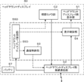
- FIG. 3 is a block diagram showing a configuration of a head mounted display according to Embodiment 1 of the present invention.
- FIG. 3 is a diagram schematically showing an ultrasonic image for head mount display and an operation image for head mount display displayed on the head mount display side display unit in the first embodiment of the present invention.
- FIG. 7 is a block diagram showing a configuration of an ultrasonic system according to another modification of the first embodiment of the present invention.
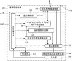
- FIG. 6 is a block diagram showing a configuration of a head mounted display according to Embodiment 2 of the present invention. It is a block diagram which shows the structure of the portable information terminal in Embodiment 2 of this invention. It is a block diagram which shows the structure of the head mounted display in Embodiment 3 of this invention. It is a block diagram which shows the structure of the portable information terminal in Embodiment 3 of this invention. It is a block diagram which shows the structure of the head mounted display in Embodiment 4 of this invention.
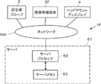
- Embodiment 4 of this invention It is a figure which shows typically a mode that the head mounted display side display part is moved in Embodiment 4 of this invention. It is a figure which shows typically the head mounted display in Embodiment 5 of this invention. It is a figure which shows the structure of the head mounted display in Embodiment 5 of this invention. It is a block diagram which shows the structure of the portable information terminal in Embodiment 5 of this invention. It is a block diagram which shows the structure of the portable information terminal in Embodiment 6 of this invention. It is a block diagram which shows the structure of the ultrasonic system which concerns on Embodiment 7 of this invention.
- a numerical range represented by “to” means a range including the numerical values before and after “to” as a lower limit value and an upper limit value.
- “identical” and “identical” include an error range generally accepted in the technical field. Further, in the present specification, when referring to “all”, “any” or “whole surface” and the like, in addition to the case of 100%, the error range generally accepted in the technical field is included, for example, 99% or more, The case where it is 95% or more, or 90% or more is included.
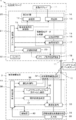
- FIG. 1 shows the configuration of an ultrasonic system 1 according to the first embodiment of the present invention.
- the ultrasonic system 1 includes an ultrasonic probe 2, a personal digital assistant 3, and a head mounted display 4.
- the ultrasonic probe 2 and the head mounted display 4 are connected to the portable information terminal 3 by wireless communication.
- the head-mounted display 4 is a display device that is mounted on the user's head and is viewed by the user who is wearing the head-mounted display 4.
- An ultrasonic image or the like is wirelessly transmitted from the portable information terminal 3 to the head-mounted display 4 and transmitted. Ultrasonic images and the like are displayed on the head mounted display 4.
- the ultrasonic probe 2 includes a transducer array 11, and a transmitter 12 and a receiver 13 are connected to the transducer array 11, respectively.
- the transmission unit 12 and the reception unit 13 form a transmission/reception unit 14, and the ultrasonic transmission/reception control unit 15 is connected to the transmission unit 12 and the reception unit 13.
- the signal processing unit 16 and the image processing unit 17 are sequentially connected to the receiving unit 13.
- the signal processing unit 16 and the image processing unit 17 constitute an image information data generation unit 19.
- the probe side wireless communication section 18 and the probe side connection terminal T1 are connected to the image processing section 17, and the communication control section 20 is connected to the probe side wireless communication section 18.
- a probe control unit 21 is connected to the ultrasonic wave transmission/reception control unit 15, the signal processing unit 16, the image processing unit 17, the probe side wireless communication unit 18, and the communication control unit 20.
- the probe-side wireless communication unit 18 and the probe control unit 21 are connected so that information can be passed bidirectionally.
- the ultrasonic probe 2 has a battery 22 built therein.
- the transmitting/receiving unit 14, the ultrasonic transmission/reception control unit 15, the image information data generation unit 19, the communication control unit 20, and the probe control unit 21 constitute a probe processor 25.
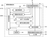
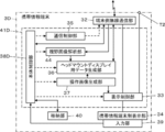
- the mobile information terminal 3 has a terminal side wireless communication unit 32, and the display control unit 33 is connected to the terminal side wireless communication unit 32.
- a communication control unit 35 and a head mounted display data generation unit 36 are connected to the terminal side wireless communication unit 32.
- the terminal side wireless communication unit 32 and the head mounted display data generation unit 36 are connected so that information can be bidirectionally passed.
- An operation image generation unit 37 is connected to the head mounted display data generation unit 36, and the operation image generation unit 37 is connected to the display control unit 33.
- the terminal side connection terminal T2 and the portable information terminal side display section 34 are connected to the display control section 33.
- the input unit 39 is arranged so as to overlap the portable information terminal side display unit 34.
- a main body control unit 38 is connected to the display control unit 33, the communication control unit 35, the head mounted display data generation unit 36, the operation image generation unit 37, and the input unit 39, and the main body control unit 38 stores the data.
- the part 40 is connected.
- the terminal side wireless communication unit 32 and the main body control unit 38 are connected so as to be capable of bidirectionally passing information.
- the main body control unit 38 and the storage unit 40 are connected so that information can be passed bidirectionally.
- the display control unit 33, the communication control unit 35, the head mount display data generation unit 36, the operation image generation unit 37, and the main body control unit 38 constitute a terminal processor 41.
- the transducer array 11 of the ultrasonic probe 2 has a plurality of ultrasonic transducers arranged one-dimensionally or two-dimensionally. Each of these vibrators transmits an ultrasonic wave in accordance with a drive signal supplied from the transmission unit 12, receives a reflected wave from the subject, and outputs an analog reception signal.
- Each vibrator is, for example, a piezoelectric ceramic typified by PZT (Lead Zirconate Titanate), a polymeric piezoelectric element typified by PVDF (PolyVinylidene DiFluoride), and a PMN-PT ( Lead Magnesium Niobate-Lead Titanate: Lead magnesium niobate-lead titanate solid solution) composed of a piezoelectric single crystal or other piezoelectric body with electrodes formed at both ends.
- PZT Lead Zirconate Titanate
- PVDF PolyVinylidene DiFluoride
- PMN-PT Lead Magnesium Niobate-Lead Titanate: Lead magnesium niobate-lead titanate solid solution
- the ultrasonic wave transmission/reception control unit 15 controls the transmission unit 12 and the reception unit 13 of the transmission/reception unit 14 to transmit an ultrasonic beam and ultrasonic waves based on the inspection mode and the scanning method instructed by the probe control unit 21. Receive echo.
- the inspection mode includes a B (luminance) mode, an M (motion) mode, a CD (color Doppler) mode, a PD (power Doppler) mode, a PW (pulse Doppler) mode, a CW (continuous wave Doppler) mode, and the like. It indicates any of the inspection modes that can be used in the ultrasonic diagnostic apparatus, and the scanning method indicates one of the electronic sector scanning method, the electronic linear scanning method, and the electronic convex scanning method.
- the transmission unit 12 of the transmission/reception unit 14 includes, for example, a plurality of pulse generators, and a plurality of transducer arrays 11 based on a transmission delay pattern selected according to a control signal from the ultrasonic transmission/reception control unit 15.
- the respective drive signals are supplied to the plurality of transducers by adjusting the delay amount so that the ultrasonic waves transmitted from the transducers of the above form an ultrasonic beam.
- a pulsed or continuous wave voltage is applied to the electrodes of the vibrators of the vibrator array 11, the piezoelectric body expands and contracts, and pulsed or continuous wave ultrasonic waves are generated from the respective vibrators.
- An ultrasonic beam focused on a certain scanning line is formed from a composite wave of those ultrasonic waves.
- the transmitted ultrasonic beam is reflected by a target such as a site of a subject and propagates toward the transducer array 11 as a so-called ultrasonic echo.
- the ultrasonic echoes propagating toward the transducer array 11 in this manner are received by the respective ultrasonic transducers forming the transducer array 11.
- each of the ultrasonic transducers forming the transducer array 11 expands and contracts by receiving the propagating ultrasonic echoes to generate electric signals, and outputs these electric signals to the receiving unit 13.
- the reception unit 13 of the transmission/reception unit 14 processes the reception signal output from the transducer array 11 according to the control signal from the ultrasonic transmission/reception control unit 15.
- the reception unit 13 has a configuration in which an amplification unit 26, an AD (Analog Digital) conversion unit 27, and a beam former 28 are connected in series.
- the amplification unit 26 amplifies the reception signal that is an analog signal input from each ultrasonic transducer that constitutes the transducer array 11, and transmits the amplified reception signal to the AD conversion unit 27.
- the AD conversion unit 27 converts the analog reception signal transmitted from the amplification unit 26 into a digital signal to acquire reception data, and sends this reception data to the beamformer 28.
- the beam former 28 adds each delay to each reception data according to the set sound velocity based on the reception delay pattern selected according to the control signal from the ultrasonic transmission/reception control unit 15 to perform addition (phasing addition). , Performs reception focus processing. By this reception focus processing, a sound ray signal in which the ultrasonic echoes are focused on a certain scanning line is generated.
- the image information data generation unit 19 of the probe processor 25 generates image information data based on the sound ray signal generated by the beam former 28 of the reception unit 13.
- the signal processing unit 16 of the image information data generating unit 19 causes the propagation distance of the sound ray signal generated by the beam former 28 of the receiving unit 13 according to the depth of the position where the ultrasonic waves are reflected.
- envelope detection processing is performed to generate a signal representing tomographic image information regarding the tissue in the subject.
- the image processing unit 17 of the image information data generation unit 19 raster-converts the signal generated by the signal processing unit 16 into an image signal in accordance with the scanning method of a normal television signal, and converts the image signal thus generated into an image signal.
- various necessary image processing such as brightness correction, gradation correction, sharpness correction, image size correction, refresh rate correction, scanning frequency correction and color correction according to the display format for the portable information terminal side display unit 34 is performed.
- the ultrasonic image signal is sent as image information data to the probe side wireless communication unit 18 or the probe side connection terminal T1.
- the probe-side wireless communication unit 18 of the ultrasonic probe 2 includes an antenna for transmitting and receiving radio waves, and modulates a carrier based on the ultrasonic image signal generated by the image information data generating unit 19.
- a transmission signal representing the ultrasound image signal is generated.
- the probe-side wireless communication unit 18 supplies the transmission signal representing the ultrasonic image signal thus generated to the antenna and transmits a radio wave from the antenna to sequentially wirelessly transmit the ultrasonic image signal.
- Carrier modulation methods include ASK (Amplitude Shift Keying), PSK (Phase Shift Keying), QPSK (Quadrature Phase Shift Keying), and 16QAM (16 Quadrature Amplitude). Modulation: 16 quadrature amplitude modulation) or the like is used.
- the probe-side wireless communication unit 18 receives a transmission signal indicating probe control information for controlling the ultrasonic probe 2 from the portable information terminal 3, and demodulates the received transmission signal to obtain the probe control.
- the information is sent to the probe controller 21.
- the probe control information is input by the user via the input unit 39 of the mobile information terminal 3, for example.
- the communication control unit 20 of the probe processor 25 controls the probe-side wireless communication unit 18 so that the ultrasonic image signal is transmitted at the transmission field intensity set by the probe control unit 21. Further, the communication control unit 20 of the probe processor 25 controls the probe-side wireless communication unit 18 so that the probe control information wirelessly transmitted from the mobile information terminal 3 is received.
- the probe-side connection terminal T1 of the ultrasonic probe 2 connects the ultrasonic probe 2 and the portable information terminal 3 by wire to transfer information bidirectionally between the ultrasonic probe 2 and the portable information terminal 3. This is the terminal used for. At this time, for example, a connection cable capable of transmitting information is inserted into the probe-side connection terminal T1.
- the probe control unit 21 of the probe processor 25 controls each unit of the ultrasonic probe 2 based on a program stored in advance.
- the battery 22 of the ultrasonic probe 2 is built in the ultrasonic probe 2 and supplies electric power to each circuit of the ultrasonic probe 2.
- the probe processor 25 including the transmitter 12, receiver 13, ultrasonic transmission/reception controller 15, signal processor 16, image processor 17, communication controller 20, and probe controller 21 of the ultrasonic probe 2 is a CPU ( Central Processing Unit: Central processing unit), and a control program that causes the CPU to perform various processing.
- FPGA Field Programmable Gate Array: Feed Programmable Gate Array
- DSP Digital Signal Processor: Digital Signal
- ASIC Application Specific Integrated Circuit: application specific integrated circuit
- other ICs Integrated Circuit: integrated circuit
- the transmission unit 12, the reception unit 13, the ultrasonic wave transmission/reception control unit 15, the signal processing unit 16, the image processing unit 17, the communication control unit 20, and the probe control unit 21 are partially or wholly integrated into one CPU or the like. It can also be integrated.
- the terminal-side wireless communication unit 32 of the mobile information terminal 3 includes an antenna for transmitting and receiving radio waves, and transmits the ultrasonic image signal transmitted by the probe-side wireless communication unit 18 of the ultrasonic probe 2.
- the signal is received via the antenna, and the ultrasonic image signal output by demodulating the received transmission signal is sent to the display control unit 33.
- the terminal side wireless communication unit 32 generates a transmission signal representing the probe control information by modulating the carrier based on the probe control information for controlling the ultrasonic probe 2 sent from the main body control unit 38. , And wirelessly transmits the generated transmission signal to the probe-side wireless communication unit 18 of the ultrasonic probe 2.
- the terminal side wireless communication unit 32 modulates the carrier based on the head mounted display data generated by the head mounted display data generation unit 36, as described later, to transmit the head mounted display data.
- a signal is generated, and the generated transmission signal is wirelessly transmitted to the head mounted display 4.
- the head mounted display data includes a head mounted display ultrasonic image signal having a display format in the head mounted display 4.
- the terminal-side wireless communication unit 32 also generates a transmission signal, which is sent from the main body control unit 38 and represents the head-mounted display control information for controlling the head-mounted display 4, and the generated transmission signal is used as the head-mounted display. 4 wirelessly.
- the carrier modulation method in the terminal side wireless communication unit 32 ASK, PSK, QPSK, 16QAM or the like is used as in the carrier modulation method in the probe side wireless communication unit 18.
- the communication control unit 35 of the terminal processor 41 controls the terminal-side wireless communication unit 32 of the mobile information terminal 3 so that the transmission signal representing the ultrasonic image signal is received from the probe-side wireless communication unit 18 of the ultrasonic probe 2. To do. In addition, the communication control unit 35 of the terminal processor 41 wirelessly transmits data to the ultrasonic probe 2 and the head mounted display 4 at the transmission radio field intensity set by the main body control unit 38 so that the data is wirelessly transmitted. The part 32 is controlled.
- the input unit 39 of the mobile information terminal 3 is for the user to perform an input operation, and includes a touch sensor that is arranged so as to overlap the mobile information terminal side display unit 34.
- the user inputs probe control information for controlling the ultrasonic probe 2 via the input unit 39, and the input probe control information is transmitted to the terminal side wireless communication via the main body control unit 38 of the terminal processor 41. It is wirelessly transmitted from the unit 32 to the ultrasonic probe 2.
- the user inputs head mount display control information for controlling the head mount display 4 via the input unit 39, and the input head mount display control information is stored in the main body control unit 38 of the terminal processor 41.
- the data is wirelessly transmitted from the terminal-side wireless communication unit 32 to the head mounted display 4 via.
- the operation image generation unit 37 of the terminal processor 41 generates an operation image displayed on the portable information terminal side display unit 34 and used by the user to perform an input operation via the touch sensor of the input unit 39.
- the operation image CS1 includes various operation buttons such as a B mode button B1 that determines the inspection mode of the ultrasonic probe 2 to the B mode, and these operation buttons are operated by the user.
- the user inputs probe control information, head mount display control information, and the like via the touch sensor of the input unit 39.
- the operation image CS1 has a CD mode button B2 that determines the inspection mode to the CD mode, a PW mode button B3 that determines the inspection mode to the PW mode, and an M inspection mode.
- An ultrasonic image is displayed on the M-mode button B4 for determining a mode, a scroll button B5 for scrolling display, a freeze button B6 for freeze-displaying an ultrasonic image, a save button B7 for saving an ultrasonic image, and a head mounted display 4.
- a display off button B8 for turning off the display of the ultrasonic image on the head mounted display 4 is included.
- the head mount display data generation unit 36 of the terminal processor 41 based on the ultrasonic image signal output from the terminal side wireless communication unit 32 and the operation image CS1 generated by the operation image generation unit 37, the head mounted display.
- the data for the head mounted display having the display format for 4 the data corresponding to the head mounted display ultrasonic image and the operation image CS1 that can be displayed on the head mounted display 4 are generated.
- the head mounted display data generation unit 36 performs brightness correction, gradation correction, sharpness correction on the ultrasonic image signal output from the terminal side wireless communication unit 32 according to the display format for the head mounted display 4.
- various necessary image processing such as correction, image size correction, refresh rate correction, scanning frequency correction, and color correction, the ultrasonic waves for the head mounted display 4 are treated as data corresponding to the ultrasonic image for the head mounted display. Generate an image signal.
- the display control unit 33 of the terminal processor 41 Under the control of the main body control unit 38, the display control unit 33 of the terminal processor 41 performs predetermined processing on the ultrasonic image signal output from the terminal-side wireless communication unit 32 and the operation image CS1 generated by the operation image generation unit 37. Then, the terminal-use ultrasonic image and the operation image CS1 having the display format for the mobile information terminal side display unit 34 and displayable on the mobile information terminal side display unit 34 are displayed on the mobile information terminal side display unit 34. ..
- the portable information terminal side display unit 34 displays the terminal ultrasonic image and the operation image CS1 under the control of the display control unit 33.
- the portable information terminal side display unit 34 includes a display device such as an LCD (Liquid Crystal Display) or an organic EL display (Organic Electroluminescence Display).
- the terminal-side connection terminal T2 of the portable information terminal 3 connects the ultrasonic probe 2 and the portable information terminal 3 by wire in the same manner as the probe-side connection terminal T1 of the ultrasonic probe 2, and connects the ultrasonic probe 2 and the portable information terminal.
- 3 is a terminal used for bidirectional information transfer. For example, one end is connected to the probe-side connection terminal T1, and the other end of the connection cable capable of transmitting information is connected to the terminal-side connection terminal T2.
- the storage unit 40 of the mobile information terminal 3 stores operation programs of the mobile information terminal 3, and the storage unit 40 includes a flash memory, a RAM (Random Access Memory), and an SD card (Secure Digital card). : Secure digital card), SSD (Solid State Drive), etc. can be used.
- the terminal processor 41 including the display control unit 33, the communication control unit 35, the head mount display data generation unit 36, the operation image generation unit 37, and the main body control unit 38 of the mobile information terminal 3 includes a CPU and various CPUs. It is composed of a control program for performing the processing of, but may be configured using FPGA, DSP, ASIC, GPU (Graphics Processing Unit), or other IC, or by combining them. It may be configured. Further, the display control unit 33, the communication control unit 35, the head mounted display data generation unit 36, the operation image generation unit 37, and the main body control unit 38 are partially or wholly integrated into one CPU or the like. You can also do it.
- the head mounted display 4 of the ultrasonic system 1 is a display device that is mounted on the user's head and is visually recognized by the user who is mounted, and has a so-called spectacle shape, as shown in FIG.
- the head mounted display 4 includes two display portions 51A and 51B, and the two display portions 51A and 51B are connected to each other by a bridge portion B, and the vine portions are respectively provided at the end portions of the two display portions 51A and 51B. A is connected.
- the bridge B is caught on the user's nose and the two vines A are caught on both ears of the user, so that the head mounted display 4 is fixed to the head of the subject.
- the two display units 51A and 51B face the left and right eyes of the user, respectively.
- a storage portion D in which various circuits necessary for the operation of the head mounted display 4, a battery and the like are stored is arranged.
- FIG. 5 shows the configuration of the head mounted display 4.
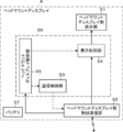
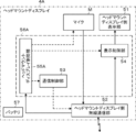
- the head mounted display 4 has a head mounted display side wireless communication unit 52, and a communication control unit 53, a display control unit 54 and a head mounted display control unit 55 are connected to the head mounted display side wireless communication unit 52.
- the head mounted display side display unit 51 is connected to the display control unit 54.
- the two display units 51A and 51B in FIG. 4 are collectively referred to as the head mounted display side display unit 51.
- the communication controller 53, the display controller 54 and the head mounted display controller 55 constitute a head mounted display processor 56.
- the head mount display 4 has a battery 57 built therein.
- the head mounted display side wireless communication unit 52, the head mounted display processor 56, and the battery 57 are housed in the housing unit D of the head mounted display 4.
- the head-mounted display side wireless communication unit 52 of the head-mounted display 4 includes an antenna for transmitting and receiving radio waves, receives head-mounted display data from the mobile information terminal 3, and receives the received head-mounted display data. The data is sent to the display controller 54. Further, the head mounted display side wireless communication unit 52 receives the head mounted display control information for controlling the head mounted display 4 from the portable information terminal 3, and the received head mounted display control information to the head mounted display control unit 55. Output.
- the head-mounted display side display unit 51 of the head-mounted display 4 has translucency so as to secure the user's visual field when the user wears the head-mounted display 4.
- the head-mounted display side display unit 51 is a display display that displays an ultrasonic image and the like. Since the head-mounted display side display unit 51 has such a configuration, it can display, for example, an ultrasonic image or the like transmitted from the mobile information terminal 3.
- the display control unit 54 of the head mount display processor 56 under the control of the head mount display control unit 55, based on the head mount display data wirelessly transmitted from the mobile information terminal 3, as shown in FIG.
- the head mount display ultrasonic image UH and the head mount display operation image CS2 according to the display format of the display side display unit 51 are displayed on the head mount display side display unit 51.
- the head mount display operation image CS2 displayed on the head mount display side display unit 51 is the same as the operation image CS1 displayed on the mobile information terminal side display unit 34.
- a display area RD for displaying the head mount display ultrasonic image UH and the head mount display operation image CS2 is displayed on the head mount display side display section 51,
- the ultrasonic image UH for head mounted display and the operation image CS2 for head mounted display are displayed in the display area RD. Since the head-mounted display-side display unit 51 has a light-transmitting property, the user visually recognizes the subject P, the ultrasonic probe 2 and the like through the head-mounted display-side display unit 51 as shown in FIG. be able to.
- the head mounted display control unit 55 of the head mounted display processor 56 controls each unit of the head mounted display 4 based on a program stored in advance, head mounted display control information wirelessly transmitted from the mobile information terminal 3, and the like. ..
- the head mounted display 4 is under the control of the head mounted display control unit 55, an ultrasonic image display mode for displaying the ultrasonic image UH for the head mounted display on the head mounted display side display unit 51, and a head mounted display side.
- the display unit 51 has an ultrasonic image non-display mode in which the head mounted display ultrasonic image UH is not displayed.
- the head mount display control unit 55 causes the head mount display 4 to enter the ultrasonic image display mode or the ultrasonic image display mode. Either the non-display mode is selected.
- the battery 57 of the head mounted display 4 is built in the head mounted display 4 and supplies electric power to each circuit of the head mounted display 4.
- the head mounted display 4 selects the ultrasonic image non-display mode from the ultrasonic image display mode and the ultrasonic image non-display mode when the ultrasonic diagnosis is started.
- the operation image CS1 displayed by the operation image generation unit 37 of the terminal processor 41 on the mobile information terminal side display unit 34 and used by the user for input operation via the touch sensor of the input unit 39. Is generated.
- the operation image CS1 operates buttons such as a B mode button B1 and a CD mode button B2 for operating the ultrasonic probe 2, a scroll button B5, and a head mounted display 4 such as a display off button B8. A button or the like for doing so can be included.
- the operation image CS1 generated in this manner is displayed on the portable information terminal side display unit 34 as shown in FIG. 3 under the control of the display control unit 33 of the portable information terminal 3.
- the user inputs the inspection mode used for ultrasonic diagnosis as probe control information via the touch sensor of the input unit 39.
- probe control information indicating that the B mode is used as the inspection mode is input.
- the B mode is used as the inspection mode.
- the probe control information input by the user is transmitted to the portable information terminal via the main body control unit 38 of the terminal processor 41. 3 is transmitted to the terminal side wireless communication unit 32, and is further wirelessly transmitted from the terminal side wireless communication unit 32 to the ultrasonic probe 2.
- the probe control information wirelessly transmitted from the terminal-side wireless communication unit 32 is received by the probe-side wireless communication unit 18 and sent to the probe control unit 21, and the probe control unit 21 further transmits the ultrasonic wave transmission/reception control unit 15 and signal processing. It is sent to the unit 16 and the image processing unit 17, respectively.
- the inspection mode used for ultrasonic diagnosis is set to the B mode.
- the ultrasonic wave transmission/reception control unit 15 of the probe processor 25 performs transmission/reception of ultrasonic waves in the transducer array 11 based on the probe control information sent from the probe control unit 21 indicating that the B mode is used as the inspection mode. Then, the transmitter/receiver 14 is controlled. At this time, first, under the control of the ultrasonic transmission/reception control unit 15, ultrasonic beams are transmitted from the plurality of ultrasonic transducers of the transducer array 11 into the subject according to the drive signal from the transmission unit 12 of the transmission/reception unit 14. To be done.
- An ultrasonic echo from the subject based on the transmitted ultrasonic beam is received by each ultrasonic transducer, a reception signal that is an analog signal is output to the reception unit 13, amplified by the amplification unit 26, and an AD conversion unit.
- the received data is obtained by AD conversion at 27.
- An acoustic ray signal is generated by subjecting the received data to a receiving focus process by the beam former 28.
- the sound ray signal generated by the beam former 28 of the reception unit 13 is subjected to predetermined signal processing by the signal processing unit 16 of the image information data generation unit 19, and becomes a signal representing a tomographic image of the tissue inside the subject.
- the signal processing unit 16 generates a signal representing a tomographic image based on the information indicating the inspection mode sent by the probe control unit 21, that is, the probe control information indicating that the B mode is used as the inspection mode. ..
- the signal generated by the signal processing unit 16 in this manner is raster-converted by the image processing unit 17 into an image signal in accordance with a normal television signal scanning method, and then displayed in the display format for the portable information terminal side display unit 34.
- Various necessary image processing such as brightness correction, gradation correction, sharpness correction, image size correction, refresh rate correction, scanning frequency correction, color correction, etc. according to the above are performed to generate an ultrasonic image signal as image information data. ..
- the ultrasonic image signal generated by the image processing unit 17 is wirelessly transmitted to the terminal-side wireless communication unit 32 of the mobile information terminal 3 via the probe-side wireless communication unit 18, and further, the terminal-side wireless communication unit 32 performs display control. It is sent to the unit 33 and the head mounted display data generation unit 36.
- the ultrasonic image signal sent from the terminal-side wireless communication unit 32 to the display control unit 33 is carried as a terminal ultrasonic image according to the display format for the portable information terminal-side display unit 34 under the control of the display control unit 33.
- the information is displayed on the information terminal side display unit 34.
- the display of the operation image CS1 performed on the portable information terminal side display unit 34 is switched to the display of the terminal ultrasonic image.
- the user displays the ultrasonic image on the head mounted display side display unit 51 via the touch sensor of the input unit 39 while the terminal ultrasonic image is displayed on the portable information terminal side display unit 34. It is possible to input the head mount display control information to that effect.
- a display ON button (not shown) for giving an instruction to display an ultrasonic image on the head mounted display side display unit 51 is displayed on the portable information terminal side display unit 34, and the displayed display ON button is the input unit.
- the head mount display control information for displaying the ultrasonic image on the head mount display side display unit 51 is input.
- the head mount display control information input in this manner is sent to the main body control unit 38, and is further sent from the main body control unit 38 to the head mount display data generation unit 36. Further, at this time, the display of the terminal ultrasonic image performed on the portable information terminal side display unit 34 is switched to the display of the operation image CS1.
- the head mounted display control information input by the user is wirelessly transmitted to the head mounted display 4 from the terminal side wireless communication unit 32 of the portable information terminal 3.
- the head mounted display control information wirelessly transmitted from the portable information terminal 3 is received by the head mounted display side wireless communication unit 52 of the head mounted display 4, and is sent to the head mounted display control unit 55.
- the head mounted display control unit 55 switches from the ultrasonic image non-display mode to the ultrasonic image display mode according to the head mounted display control information.
- the head mounted display data generation unit 36 of the portable information terminal 3 receives the head mounted display control information for displaying the ultrasonic image on the head mounted display side display unit 51 from the main body control unit 38, the terminal side wireless communication unit. Based on the ultrasonic image signal sent from 32 to the head mounted display data generation unit 36, brightness correction, gradation correction, sharpness correction, image size correction, and refresh according to the display format for the head mounted display side display unit 51.
- An ultrasonic image signal for the head mounted display 4 is generated by performing various necessary image processings such as rate correction, scanning frequency correction and color correction.
- the head mounted display data generation unit 36 also corrects the brightness of the operation image generated by the operation image generation unit 37 according to the display format for the head mounted display side display unit 51, gradation correction, and sharpness correction.
- Various necessary image processes such as image size correction, refresh rate correction, scanning frequency correction, color correction, etc. are performed to generate data corresponding to the operation image for the head mounted display 4.
- the head-mounted display data generation unit 36 generates head-mounted display data including the ultrasonic image signal for the head-mounted display thus generated and the data corresponding to the operation image for the head-mounted display 4. Then, it is sent to the terminal side wireless communication unit 32 of the portable information terminal 3. The head-mounted display data sent from the head-mounted display data generation unit 36 to the terminal-side wireless communication unit 32 is wirelessly transmitted from the terminal-side wireless communication unit 32 to the head-mounted display 4.
- the head mounted display data wirelessly transmitted from the mobile information terminal 3 is received by the head mounted display side wireless communication unit 52 and sent to the display control unit 54.
- the display control unit 54 causes the head mount display side display unit 51 to display the head mount display ultrasonic image UH and the head mount display operation image CS2 based on the head mount display data, as shown in FIG. ..
- the ultrasonic image UH for head mounted display and the operation image CS2 for head mounted display are displayed in the display area RD.
- the head-mounted display-side display unit 51 has a light-transmitting property, the user can visually recognize the subject P, the ultrasonic probe 2, and the like through the head-mounted display-side display unit 51.
- the input unit 39 of the input unit 39 is displayed in accordance with the operation image CS1 displayed on the portable information terminal side display unit 34.
- an operation related to the display mode of the head mounted display side display section 51 is performed. For example, as shown in FIG. 3, when the freeze button B6 displayed on the portable information terminal side display unit 34 is touched by the user, the ultrasonic image for head mounted display displayed on the head mounted display side display unit 51.
- Head mount display control information indicating that UH is freeze-displayed is wirelessly transmitted to the head mount display 4 via the terminal side wireless communication unit 32, and is transmitted to the head mount display side display unit 51 under the head mount display control unit 55.
- the displayed ultrasonic image UH for head-mounted display is freeze-displayed.
- the display of the head mounted display ultrasonic image UH displayed on the head mounted display side display unit 51 is turned off.
- the head mount display control information to that effect is wirelessly transmitted to the head mount display 4 via the terminal side wireless communication unit 32, and the ultrasonic image non-display mode is selected by the head mount display control unit 55.
- the ultrasonic image non-display mode is selected by the head mount display control unit 55
- the ultrasonic image UH for the head mount display, the operation image CS2 for the head mount display, and the display area RD are the head mount.
- the display is not displayed on the display unit 51. In this case, the user can visually recognize the front view through the head mount display side display unit 51 without being disturbed by the head mount display operation image CS2 and the display area RD.
- the operation image CS1 and the terminal ultrasonic image can be displayed on the portable information terminal side display unit 34. It can.
- the user can confirm the ultrasonic image by visually recognizing the portable information terminal side display unit 34 even when the head mounted display ultrasonic image UH is not displayed on the head mounted display side display unit 51. You can In this way, the operation of the ultrasonic system 1 of the present invention is performed.
- the ultrasonic diagnostic apparatus is usually used by the user in a state where the main body of the ultrasonic diagnostic apparatus is installed at a position apart from the ultrasonic probe such as bedside. Therefore, there is a problem in mobility such that the place where ultrasonic diagnosis is performed is limited.
- the user can perform ultrasonic diagnosis of the subject by preparing the ultrasonic probe 2, the portable information terminal 3, and the head mount display 4 at hand, and further, the head Since the ultrasonic image UH for head-mounted display can be confirmed by visually observing the display section 51 on the mount display side, it is possible to improve the operability and the mobility of the user when performing ultrasonic diagnosis. You can
- the user touches the operation image CS1 displayed on the portable information terminal side display unit 34 to perform an input operation of the ultrasound system 1, and
- the head mounted display ultrasonic image UH is displayed on the head mounted display side display unit 51 according to the user's input operation, so that the user can observe the head mounted display ultrasonic image UH while inspecting the subject.
- the input operation for ultrasonic diagnosis can be easily performed.
- the user can display the mobile information terminal 3 at hand. It is possible to perform the input operation via the input unit 39 of the mobile information terminal 3 by grasping the arrangement of the buttons in the operation image CS1 without looking at the line of sight.
- the head mounted display 4 selects either the ultrasonic image display mode or the ultrasonic image non-display mode in accordance with the user's input operation via the input unit 39 of the portable information terminal 3, the user does not The ultrasonic image UH for head-mounted display can be confirmed at a desired timing according to the inspection situation.
- the head mount display side display unit 51 displays the head mount display operation image CS2, but the head mount display side display unit 51 displays only the head mount display ultrasonic image UH.
- the operation image CS2 for head mounted display may not be displayed.
- the user observes the head mounted display ultrasonic image UH while inspecting the subject.
- the input operation for ultrasonic diagnosis can be easily performed.
- the convenience in ultrasonic diagnosis can be further improved.
- the B mode is used as the inspection mode, but the M mode or the like can also be used.
- the image information data generation unit 19 is provided with a Doppler processing unit that performs so-called Doppler processing, so that the CD mode, PD mode, PW mode, CW mode, and the like can be used.
- the operation image CS1 is used as a button for setting the inspection mode, and the probe control information indicating that the M mode, the CD mode, the PD mode, the PW mode, the CW mode, or the like is used as the inspection mode. It is desirable to include a button to enter.
- the operation image CS1 includes a measurement menu for selecting measurement items when performing measurement on the ultrasonic image, a user interface such as a keyboard for inputting information about the subject, and the ultrasonic image. It is also possible to display a menu or the like for selecting a body mark to be displayed overlaid on.
- the measurement items include, for example, measurement of the distance between two points on the ultrasonic image, measurement of the area of the site on the ultrasonic image, measurement of blood flow velocity using Doppler signals, and the like.
- the mobile information terminal side display unit when measuring a distance, an area, and the like on the ultrasonic image, for example, although not shown, by providing the mobile information terminal 3 with a measurement unit for performing a process related to measurement, the mobile information terminal side display unit is provided. It is also possible to perform a touch operation on a measurement caliper or the like on the terminal ultrasonic image displayed on the screen 34 to measure the distance and area on the ultrasonic image.
- the head mount display data generation unit 36 outputs data corresponding to the same display as the display currently performed on the portable information terminal side display unit 34 and in accordance with the display format for the head mounted display 4, to the head mounted display. It can be generated as the use data and transmitted to the head mounted display 4 via the terminal side wireless communication unit 32.
- the user can perform measurement on the ultrasonic image while confirming the display on the head mounted display side display unit instead of confirming the display on the portable information terminal side display unit 34.
- a body mark for displaying the ultrasonic image on the portable information terminal side display unit 34 is displayed, a probe mark displayed further on the displayed body mark is displayed, and a probe mark of the displayed probe mark is displayed.
- the position can also be adjusted by the user by touch operation.
- the head mount display data generation unit 36 causes the data that corresponds to the same display as the display currently performed on the portable information terminal side display unit 34 and that follows the display format for the head mounted display 4 to be mounted on the head mount display 4.
- the user does not confirm the display on the portable information terminal side display unit 34 but the head mounted display side display unit.
- the position of the probe mark can be adjusted while checking the display at 51.
- the operation image CS1 displayed on the portable information terminal side display unit 34 is used for confirming the operation of the ultrasonic system 1 corresponding to the ultrasonic image signals sequentially transmitted from the terminal side wireless communication unit 32. It is also possible to display a small ultrasonic image. In this case, the user can check the portable information terminal side display unit 34 instead of the head mounted display side display unit 51 so that the ultrasonic probe 2 is currently operating and the ultrasonic image signals are sequentially acquired. Can be confirmed.
- the display mode of the button touched by the user can be changed.
- the color of the button touched by the user can be changed, and the outline color of the button touched by the user can also be changed.
- the display mode of the button of is changed. In this case, the user confirms the head mount display operation image CS2 displayed on the head mount display side display unit 51 to more clearly identify what input operation is currently performed by the user. You can figure it out.
- wireless communication is performed between the ultrasonic probe 2 and the mobile information terminal 3, and between the mobile information terminal 3 and the head mounted display 4, respectively.
- the wireless communication system between the ultrasonic probe 2 and the portable information terminal 3 and the wireless communication system between the portable information terminal 3 and the head mounted display 4 are different from each other. Is desirable.
- the frequency band for wireless communication between the ultrasonic probe 2 and the mobile information terminal 3 and the frequency band for wireless communication between the mobile information terminal 3 and the head mounted display 4 can be different from each other.
- a frequency of 2.4 GHz band is used for wireless communication between the ultrasonic probe 2 and the mobile information terminal 3
- a 5 GHz band is used for wireless communication between the mobile information terminal 3 and the head mounted display 4.
- the communication standard used for wireless communication between the ultrasonic probe 2 and the mobile information terminal 3 and the communication standard used for wireless communication between the mobile information terminal 3 and the head mounted display 4 are mutually defined. It can be different.
- the ultrasonic probe 2 and the portable information terminal 3 are connected using a connection cable CC capable of transmitting information.
- the ultrasonic probe 2 and the portable information terminal 3 can be connected by wire.
- the ultrasonic system 1 by detecting that the connection cable CC is connected to the probe-side connection terminal T1 and the terminal-side connection terminal T2, the radio wave between the ultrasonic probe 2 and the portable information terminal 3 is detected. The connection can be stopped. In this way, the communication state between the ultrasonic probe 2 and the portable information terminal 3 can be stabilized.
- the terminal ultrasonic image is displayed on the portable information terminal side display unit 34, but instead of displaying only the operation image CS1 on the portable information terminal side display unit 34, the head mounted display is displayed. It is also possible to always display the head mounted display ultrasonic image UH on the side display unit 51.
- the operation image CS1 and the terminal ultrasonic image are displayed on the mobile information terminal 3
- the operation image CS1 and the terminal ultrasonic image are simultaneously displayed on the mobile information terminal side display unit 34.
- they can be displayed by switching from each other. Thereby, even when the head mounted display ultrasonic image UH is not displayed on the head mounted display side display unit 51, the user can perform ultrasonic diagnosis of the subject while checking the portable information terminal side display unit 34. Is possible.
- an external data memory for storing an ultrasonic image signal or the like transmitted from the terminal side wireless communication unit 32 can be connected to the mobile information terminal 3.
- Such external data memory includes flash memory, HDD (Hard Disc Drive: hard disk drive), SSD, FD (Flexible Disc: flexible disk), MO disc (Magneto-Optical disc: magneto-optical disc), MT (Magnetic Tape). : Magnetic tape), RAM, CD (Compact Disc: compact disc), DVD (Digital Versatile Disc: digital versatile disc), SD card, a recording medium such as a USB memory, or a server can be used.
- the portable information terminal 3 and the external data memory can be wirelessly connected or can be wired.
- an ultrasonic image signal is generated by the ultrasonic probe 2 and the generated ultrasonic image signal is wirelessly transmitted to the mobile information terminal 3.
- the envelope detection is performed on the sound ray signal.
- the processed signal is generated by the ultrasonic probe 2, the generated signal is wirelessly transmitted to the mobile information terminal 3, and an ultrasonic image signal is generated by the mobile information terminal 3 based on the wirelessly transmitted signal. It may be generated.
- the image information data generation unit 19 of the ultrasonic probe 2 may include only the signal processing unit 16, and the mobile information terminal 3 may include the image processing unit 17.
- the probe side wireless communication section 18 and the probe side connection terminal T1 are connected to the signal processing section 16 of the image information data generating section 19.
- the terminal side wireless communication unit 32, the display control unit 33, and the head mounted display data generation unit 36 are connected to the image processing unit 17 of the mobile information terminal 3.
- a signal obtained by performing envelope detection processing on the sound ray signal is generated as image information data by the image information data generation unit 19.
- the image information data generated by the image information data generation unit 19 is transmitted from the probe-side wireless communication unit 18 to the mobile information terminal 3, and the transmitted image information data is transmitted from the terminal-side wireless communication unit 32 to the mobile information terminal. 3 to the image processing unit 17.
- the image processing unit 17 of the mobile information terminal 3 generates an ultrasonic image signal based on the image information data received from the terminal side wireless communication unit 32.
- the generated ultrasonic image signal is sent to the display control unit 33 and the head mounted display data generation unit 36.
- the ultrasonic image signal received by the display control unit 33 is displayed on the portable information terminal side display unit 34 as a terminal ultrasonic image under the control of the display control unit 33.
- the ultrasonic image signal received by the head mounted display data generation unit 36 is wirelessly transmitted to the head mounted display 4 from the terminal side wireless communication unit 32 as head mounted display data, and is transmitted as a head mounted display ultrasonic image UH. , Is displayed on the head-mounted display side display section 51.
- the image information data generation unit 19 of the ultrasonic probe 2 includes only the signal processing unit 16 and the mobile information terminal 3 includes the image processing unit 17, the image information data generation unit 19 of the ultrasonic probe 2 does not operate. Similar to the case where both the signal processing unit 16 and the image processing unit 17 are provided, the user prepares the ultrasonic probe 2, the portable information terminal 3, and the head mounted display 4 at hand to perform ultrasonic diagnosis of the subject. Further, since it is possible to confirm the head mounted display ultrasonic image UH by visually recognizing the head mounted display side display unit 51, it is possible to improve operability when the user performs ultrasonic diagnosis, In addition, mobility can be improved.
- the input operation is performed by the user via the input unit 39 of the mobile information terminal 3, but the input operation can also be performed based on the voice of the user, for example.
- the head mounted display 4A according to the second embodiment is different from the head mounted display 4 according to the first embodiment shown in FIG.
- the display control unit 55A is provided.
- the head mounted display side wireless communication unit 52 and the head mounted display control unit 55A are connected to the microphone M.
- the communication control unit 53, the display control unit 54, and the head mount display control unit 55A constitute a head mount display processor 56A.
- the microphone M of the head mounted display 4A is for acquiring the user's voice.
- the microphone M acquires the user's voice as an analog signal, converts the acquired sound into a digital signal, and generates voice data.
- the audio data generated by the microphone M is sent to the head mounted display side wireless communication unit 52, and wirelessly transmitted from the head mounted display side wireless communication unit 52 to the portable information terminal 3A shown in FIG.
- mobile information terminal 3A according to the second exemplary embodiment is different from mobile information terminal 3 according to the first exemplary embodiment shown in FIG. 1 in that voice analysis unit 42 is added and main body control is performed instead of main body control unit 38. It is provided with a portion 38A.
- the voice analysis unit 42 is connected to the terminal side wireless communication unit 32, and the main body control unit 38A is connected to the voice analysis unit 42.
- the display control unit 33, the communication control unit 35, the head mounted display data generation unit 36, the operation image generation unit 37, the main body control unit 38A, and the voice analysis unit 42 constitute a terminal processor 41A.
- the voice analysis unit 42 of the terminal processor 41A receives, via the terminal-side wireless communication unit 32, voice data generated by the microphone M of the head-mounted display 4A and wirelessly transmitted from the head-mounted display-side wireless communication unit 52. Analyze voice data. Furthermore, the voice analysis unit 42 extracts the voice of the user based on the voice data, analyzes the extracted voice of the user, and controls the analyzed voice as body operation control as input operation information representing an input operation from the user. It is sent to the section 38A. The main body control unit 38A controls each unit of the mobile information terminal 3A according to the received input operation information.
- the microphone M acquires the voice of the user to generate voice data, and the generated voice data is the head data. It is wirelessly transmitted from the mount display side wireless communication unit 52 to the portable information terminal 3A.
- the voice data wirelessly transmitted is sent to the voice analysis unit 42 of the mobile information terminal 3A via the terminal-side wireless communication unit 32, and analyzed by the voice analysis unit 42.
- the voice analysis unit 42 analyzes the voice data and sends input operation information to the effect that the head mounted display side display unit 51 displays the head mounted display ultrasonic image UH to the main body control unit 38A.
- the input operation information sent to the main body control unit 38A is sent as head mount display control information from the main body control unit 38 to the terminal side wireless communication unit 32, and is wirelessly sent from the terminal side wireless communication unit 32 to the head mount display 4A.
- the head mounted display control unit 55A selects the ultrasonic image display mode according to the received head mounted display control information. As a result, the head mounted display ultrasonic image UH is displayed on the head mounted display side display unit 51.
- the head-mounted display control unit 55A selects the image non-display mode, and the head-mounted display ultrasonic image UH. Disappears from the head-mounted display side display section 51.
- the input operation can be performed by the voice of the user. Therefore, for example, even if both hands of the user are closed during ultrasonic diagnosis, It is possible to easily observe the ultrasonic image UH for head mounted display and perform an input operation for ultrasonic diagnosis while inspecting the subject.
- Embodiment 3 In the second embodiment, the input operation is performed based on the voice of the user, but the input operation may be performed based on the eye movement of the user such as blinking of the user and movement of the line of sight.
- the head mounted display 4B according to the third embodiment is different from the head mounted display 4A according to the second embodiment shown in FIG. 11 in that an eye camera unit C1 is provided instead of the microphone M, and a head mounted display control unit.
- a head mount display controller 55B is provided instead of 55A.
- the head mounted display side wireless communication unit 52 and the head mounted display control unit 55B are connected to the eye camera unit C1. Further, the communication controller 53, the display controller 54, and the head mounted display controller 55B constitute a head mounted display processor 56B.
- the eye camera unit C1 of the head mounted display 4B continuously generates eye images of the user's eyes at a predetermined frame rate.
- the eye camera unit C1 is a photographing lens facing the user's eye, an image sensor for photographing the user's eye through the photographing lens, and an eye image signal that is an analog signal, and is acquired by the image sensor. It has an analog signal processing circuit that amplifies the eye image signal and converts it to a digital signal, and a digital signal circuit that performs various corrections such as gain correction on the converted digital signal to generate an eye image. ..
- the analog signal processing circuit and the digital signal processing circuit may be incorporated in the head mounted display processor 56B.
- the eye image generated by the eye camera unit 1C is wirelessly transmitted from the head mounted display side wireless communication unit 52 to the mobile information terminal 3B shown in FIG.
- mobile information terminal 3B according to the third embodiment is different from mobile information terminal 3A according to the second embodiment shown in FIG. 2 in that eye movement detection unit 43 is provided instead of voice analysis unit 42, and main body control A main body control unit 38B is provided instead of the unit 38A.
- the terminal-side wireless communication unit 32 is connected to the eye movement detection unit 43
- the eye movement detection unit 43 is connected to the main body control unit 38B.
- the display control unit 33, the communication control unit 35, the head mount display data generation unit 36, the operation image generation unit 37, the main body control unit 38B, and the eye movement detection unit 43 constitute a terminal processor 41B.
- the eye movement detection unit 43 of the terminal processor 41B generates an eye image continuously generated by the eye camera unit C1 of the head mounted display 4B and wirelessly transmitted from the head mounted display side wireless communication unit 52, and the terminal side wireless communication unit 32. Based on the received eye image, the user's eye movement such as blinking of the user and movement of the line of sight is detected. Furthermore, the eye movement detection unit 43 sends the detected eye movement of the user to the main body control unit 38B as input operation information indicating an input operation from the user. The main body control unit 38B controls each unit of the mobile information terminal 3B according to the received input operation information.
- the head mount display ultrasonic image UH is not displayed on the head mount display side display unit 51, that is, when the ultrasonic image non-display mode is selected by the head mount display control unit 55B.
- the head mount display side display unit 51 is caused to display an item for displaying an ultrasonic image on the head mount display side display unit 51, and the eye movement detection unit 43 causes the user to gaze at the item for a certain period of time. It is possible to detect that the user's eyes are moving.
- the eye movement detection unit 43 sends the detected eye movement of the user to the main body control unit 38B.
- the main body control unit 38B causes the head mount display side display unit 51 to watch the user's attention to the item displayed on the head mount display side display unit 51 to display the ultrasonic image for a certain period of time.
- the input operation information is regarded as the input operation information for displaying the ultrasonic image UH for use, and the input operation information is sent to the terminal side wireless communication unit 32.
- the transmitted input operation information is wirelessly transmitted from the terminal side wireless communication unit 32 to the head mounted display 4B as head mounted display control information, and is transmitted to the head mounted display control unit 55B via the head mounted display side wireless communication unit 52.
- the head mounted display control unit 55B selects the ultrasonic image display mode according to the received head mounted display control information. As a result, the head mounted display ultrasonic image UH is displayed on the head mounted display side display unit 51.
- the head mounted display ultrasonic image UH is displayed on the head mounted display side display unit 51, that is, when the ultrasonic image display mode is selected by the head mounted display control unit 55B
- the head is An item indicating that an ultrasonic image is not displayed on the mount display side display unit 51 is displayed on the head mount display side display unit 51
- the eye movement detection unit 43 indicates that the user is gazing at the item for a certain period of time.
- the main body control unit 38B causes the head mount display side display unit 51 to display, for example, that the user pays attention to an item displayed on the head mount display side display unit 51 that the ultrasonic image is not displayed for a certain period of time.
- the input operation information is transmitted to the terminal side wireless communication unit 32 by regarding it as the input operation information indicating that the for-use ultrasonic image UH is not displayed.
- the transmitted input operation information is wirelessly transmitted from the terminal side wireless communication unit 32 to the head mounted display 4B as head mounted display control information, and is transmitted to the head mounted display control unit 55B via the head mounted display side wireless communication unit 52. To be done.
- the head mounted display control unit 55B selects the ultrasonic image non-display mode, and the head mounted display ultrasonic image UH is not displayed on the head mounted display side display unit 51.
- the input operation can be performed by the movement of the user's eyes. Therefore, for example, even if both hands of the user are blocked during ultrasound diagnosis, Can easily perform observation of the ultrasonic image UH for head mounted display and input operation for ultrasonic diagnosis while inspecting the subject.
- the input operation is performed via the input unit 39 of the portable information terminal 3, in the second embodiment, the input operation is performed by the voice of the user, and in the third embodiment, the eye movement of the user.
- the method of input operation is not limited to these.
- a so-called foot switch may be provided in the ultrasonic system, and an input operation may be performed by the user via the foot switch.
- the foot switch is pressed a predetermined number of times within a certain time
- the head mount display ultrasonic image UH is displayed on the head mount display side display unit 51. It is possible to perform an input operation such as not displaying the ultrasonic image UH for the head mounted display on the unit 51, or displaying the ultrasonic image UH for the head mounted display on the head mounted display side display unit 51 in a frozen state.
- Embodiment 4 It is detected whether or not the head-mounted display-side display unit 51 is out of a predetermined arrangement position, that is, whether or not the user visually recognizes the front view through the head-mounted display-side display unit 51, and the detected result is detected. According to the above, the head mounted display 4 can select either the ultrasonic image display mode or the ultrasonic image non-display mode.
- the head mounted display 4C according to the fourth embodiment is different from the head mounted display 4 according to the first embodiment shown in FIG. 5 in that an arrangement position sensor PS and a display moving unit MD are added to control the head mounted display.
- a head mount display control unit 55C is provided instead of the unit 55.
- an arrangement position sensor PS is arranged in the vicinity of the head mounted display side display unit 51, and a head mounted display control unit 55C is connected to the arrangement position sensor PS.
- the display moving unit MD is connected to the head mounted display side display unit 51, and the head mounted display control unit 55C is connected to the display moving unit MD.
- the communication control unit 53, the display control unit 54, and the head mount display control unit 55C constitute a head mount display processor 56C.
- the placement position sensor PS of the head mounted display 4C is a sensor that detects whether or not the head mounted display side display unit 51 is located at a predetermined placement position.
- the determined arrangement position of the head-mounted display-side display unit 51 is, for example, the position of the head-mounted display-side display unit 51 facing the user's eye EY as represented by the dotted line in FIG. That is.
- the head-mounted display side display unit 51 is located at the determined arrangement position, the user clearly recognizes the head-mounted display ultrasonic image UH and the like displayed on the head-mounted display side display unit 51.
- the front field of view can be visually recognized through the head mounted display side display section 51.
- the detection result of the arrangement position sensor PS is sent to the head mounted display controller 55C.
- the head mount display control unit 55C selects the ultrasonic image display mode and detects the placement position when the placement position sensor PS detects that the head mount display side display unit 51 is located at the determined placement position.
- the ultrasonic image non-display mode is selected when the sensor PS detects that the head-mounted display-side display section 51 is not located at the determined arrangement position.
- the head-mounted display-side display unit 51 is rotatable around a rotation axis H between a predetermined arrangement position and a predetermined standby position different from the predetermined arrangement position, as shown in FIG. 14, for example. Is configured.
- the predetermined standby position of the head-mounted display-side display unit 51 is the position of the head-mounted display-side display unit 51 as indicated by the solid line in FIG.
- the display moving unit MD of the head mounted display 4C is for moving the head mounted display side display unit 51 between a predetermined arrangement position and a predetermined standby position.
- the display moving unit MD has, for example, an electric motor built therein, and moves the head mounted display side display unit 51 by the driving force of the electric motor.
- the display moving unit MD is, for example, when an input operation to move the head mounted display side display unit 51 to a predetermined arrangement position is performed by the user via the input unit 39 of the mobile information terminal 3.
- the head mounted display control unit 55C Under the control of the head mounted display control unit 55C, the head mounted display side display unit 51 is moved to the arrangement position as shown in FIG. Accordingly, the placement position sensor PS detects that the head mount display side display unit 51 is located at the determined placement position, and the head mount display control unit 55C causes the ultrasonic wave to be detected by the head mount display control unit 55C according to the detection result of the placement position sensor PS.
- the image display mode is selected, and the head mounted display ultrasonic image UH is displayed on the head mounted display side display unit 51.
- the display moving unit MD is, for example, when an input operation to move the head mounted display side display unit 51 to a predetermined standby position is performed by the user via the input unit 39 of the mobile information terminal 3. Under the control of the head mounted display control unit 55C, the head mounted display side display unit 51 is moved to the standby position. Accordingly, the placement position sensor PS detects that the head mount display side display unit 51 is not located at the determined placement position, and the head mount display control unit 55C causes the ultrasonic wave to be detected by the head mount display controller 55C according to the detection result of the placement position sensor PS. The image non-display mode is selected and the head mounted display ultrasonic image UH is not displayed on the head mounted display side display unit 51. Further, at this time, the terminal ultrasonic image and the operation image CS1 are displayed on the portable information terminal side display unit 34.
- the display moving unit MD of the head mounted display 4C is changed to the head mounted display side display unit according to the user's input operation via the input unit 39 of the portable information terminal 3.
- 51 is moved between a predetermined arrangement position and a predetermined standby position, and the head mount display control unit 55C causes the ultrasonic image display mode and the ultrasonic image non-display according to the detection result of the arrangement position sensor PS. Since any one of the modes is selected, the user can check the ultrasonic image UH for head mounted display at a desired timing according to the examination status of the subject.
- the head mounted display control unit 55C when the placement position sensor PS detects that the head mounted display side display unit 51 is located at the determined placement position, the head mounted display control unit 55C causes an ultrasonic image. Although the display mode is selected, in this state, the head mounted display control unit 55C further follows the ultrasonic image display mode and the ultrasonic image non-display according to the user's input operation via the input unit 39 of the mobile information terminal 3. You can select any of the modes.
- the head mounted display side display unit 51 is automatically moved by the display moving unit MD, but the user can also manually move the head mounted display side display unit 51. Even in this case, the placement position sensor PS detects whether or not the head mount display side display unit 51 is located at the determined placement position, and the head mount display control unit 55C indicates the detection result of the placement position sensor PS. Based on this, either the ultrasonic image display mode or the ultrasonic image non-display mode is selected.
- the aspect of the fourth embodiment is described as being applied to the first embodiment, the aspect of the second and third embodiments can be similarly applied.
- the display moving unit MD is set under the control of the head mounted display control unit 55C according to the input operation by the user's voice.
- the head mounted display side display unit 51 can be moved between the arranged position and the determined standby position.
- the display moving unit MD controls the head mounted display control unit 55C according to the input operation by the user's eye movement.
- the head-mounted display side display unit 51 can be moved between the predetermined arrangement position and the predetermined standby position under the.
- the head mount display data is generated based on the image information data generated by the ultrasonic probe 2, that is, the ultrasonic image signal, and the operation image generated by the mobile information terminal 3.
- the head-mounted display data may be generated by generating a field-of-view image obtained by capturing a field of view in front of the head-mounted display.
- the head mounted display 4D includes a visual field camera unit C2 that generates a visual field image obtained by photographing the visual field in front of the user.
- the visual field camera unit C2 is attached to the connecting portion of the left display unit 51B and the vine portion A, and the photographing lens F is arranged on the front surface of the visual field camera unit C2.
- the head mounted display 4D is different from the head mounted display 4 in the first embodiment shown in FIG. 5 in that a visual field camera unit C2 is added, and instead of the head mounted display control unit 55, a head mounted display control unit. It is equipped with 55D. Further, the communication control unit 53, the display control unit 54, and the head mount display control unit 55D constitute a head mount display processor 56D.
- the field-of-view camera unit C2 of the head-mounted display 4D continuously generates field-of-view images obtained by shooting the field of view in front of the user through the shooting lens F at a predetermined frame rate.
- the visual field camera unit C2 photographs the visual field in front of the user through the photographing lens F, and amplifies the visual field image signal obtained by the image sensor and the image sensor that obtains the visual field image signal that is an analog signal.
- An analog signal processing circuit for converting the converted digital signal into a digital signal and a digital signal processing circuit for performing various corrections such as gain correction on the converted digital signal to generate a visual field image are incorporated.
- the analog signal processing circuit and the digital signal processing circuit may be incorporated in the head mounted display processor 56D.
- the visual field images continuously generated by the visual field camera unit C2 are sent to the head mounted display side wireless communication unit 52, and wirelessly transmitted to the mobile information terminal 3D shown in FIG. 17 by the head mounted display side wireless communication unit 52. ..
- the mobile information terminal 3D according to the fifth embodiment is different from the mobile information terminal 3 according to the first embodiment shown in FIG. 1 in that a visual field image analysis unit 44 is added and the main body control unit 38 is replaced by a main body.
- the controller 38D is provided.
- the visual field image analysis unit 44 is connected to the terminal side wireless communication unit 32, and the visual field image analysis unit 44 is connected to the head mount display data generation unit 36 and the main body control unit 38D.
- the display control unit 33, the communication control unit 35, the head mounted display data generation unit 36, the operation image generation unit 37, the main body control unit 38D, and the visual field image analysis unit 44 constitute a terminal processor 41D.
- the visual field image analysis unit 44 of the terminal processor 41D receives the visual field image wirelessly transmitted from the head mounted display 4D via the terminal side wireless communication unit 32, and analyzes the received visual field image. For example, the visual field image analysis unit 44 detects the screen of the portable information terminal side display unit 34 shown in the received visual field image, and sends the detection result to the head mounted display data generation unit 36.
- the head mounted display data generation unit 36 of the terminal processor 41D displays the screen of the portable information terminal side display unit 34 when the screen image of the portable information terminal side display unit 34 included in the visual field image is detected by the visual field image analysis unit 44.
- the head-view display data is generated by using the field-of-view image of the portion that represents the image in place of the operation image generated by the operation image generation unit 37.
- the head-mounted display data thus generated is sent to the terminal-side wireless communication unit 32, and wirelessly transmitted to the head-mounted display 4D by the terminal-side wireless communication unit 32.
- the head mount display data wirelessly transmitted to the head mount display 4D is sent to the display control unit 54 via the head mount display side wireless communication unit 52.
- the head mount display ultrasonic image UH and the visual field image of the portion representing the screen of the portable information terminal side display unit 34 are head mounted based on the head mount display data. It is displayed on the display side display unit 51.
- a view field image of a portion showing the screen of the portable information terminal side display unit 34 is displayed.
- the user's finger touching the operation image CS1 displayed on the mobile information terminal side display unit 34 is also displayed in the view field image of the portion showing the screen of the mobile information terminal side display unit 34, so that the user Even if the line of sight is not directed to the mobile information terminal 3D, the button arrangement in the operation image CS1 can be more surely grasped and the input operation via the input unit 39 of the mobile information terminal 3 can be performed.
- the visual field image analysis unit 44 analyzes the visual field image received from the terminal side wireless communication unit 32 to determine the distance between the visual field camera unit C2 of the head mounted display 4D and the ultrasonic probe 2. Can be calculated as the line-of-sight distance.
- the field-of-view image analysis unit 44 is a so-called color disclosed in “Color aperture imaging technology capable of accurately measuring a distance from one image captured by a monocular camera” (Toshiba review VOL73 No. 1, January 2018). By using the aperture imaging model, the line-of-sight distance of the user can be calculated by utilizing the difference in blurring due to the color.
- the head-mounted display data generation unit 36 of the terminal processor 41D displays on the head-mounted display side based on the calculated value of the user's line-of-sight distance.
- the display area RD displayed on the unit 51, the ultrasonic image UH for the head mounted display, the operation image CS2 for the head mounted display, the size of the visual field image of the portion representing the screen of the portable information terminal side display unit 34 are set, and the head is set. Generate mount display data.
- the head mount display data generation unit 36 stores, for example, the relationship between the display area RD and the user's line-of-sight distance in advance, and further, the head mount display ultrasonic image UH, the head mount display operation image CS2, By setting the size of the field-of-view image of the portion representing the screen of the portable information terminal side display unit 34 to be a size of a certain ratio with respect to the size of the display region RD, it is displayed on the head mounted display side display unit 51. You can set the size of various images.
- the head mount display data generation unit 36 sets the size of the display area RD to increase as the value of the line-of-sight of the user decreases, and decreases the size of the display area RD as the line-of-sight of the user increases.
- the visual field image generated by the visual field camera unit C2 of the head mounted display 4D is image-analyzed by the visual field image analysis unit 44 of the portable information terminal 3D, and the head mounted The display data generation unit 36 further generates the head mount display data in consideration of the result of the image analysis performed by the visual field image analysis unit 44, and the head mount display side display unit based on the generated head mount display data. Since various images such as various ultrasonic images UH for head-mounted display are displayed on 51, convenience in ultrasonic diagnosis can be improved.
- the ultrasonic images and the like are displayed on the portable information terminal side display unit 34 and the head mounted display side display unit 51, respectively. It is preferable that the index is displayed.
- the safety evaluation index is an index for evaluating the safety against the effect of ultrasonic waves on the living body, for example, the safety of mechanical action such as radiation pressure and vibration of ultrasonic waves in the living body.
- MI Mechanical Index
- TI Thermal Index: Thermal Index
- the mobile information terminal 3E according to the sixth embodiment is different from the mobile information terminal 3 according to the first embodiment shown in FIG. 1 in that a safety evaluation index calculation unit 45 is added and a main body control unit 38E is provided instead of the main body control unit 38. It is a thing.
- the display control unit 33 and the head mount display data generation unit 36 are connected to the safety evaluation index calculation unit 45, and the safety evaluation index calculation unit 45 is connected to the main body control unit 38E. ..
- the display control unit 33, the communication control unit 35, the head mounted display data generation unit 36, the operation image generation unit 37, the main body control unit 38E, and the safety evaluation index calculation unit 45 constitute a terminal processor 41E.
- the safety evaluation index calculation unit 45 of the terminal processor 41E calculates and calculates the safety evaluation index based on the conditions of ultrasonic wave transmission/reception controlled by the ultrasonic wave transmission/reception control unit 15 of the ultrasonic probe 2 shown in FIG.
- the generated safety evaluation index is sent to the display control unit 33 and the head mount display data generation unit 36.
- the ultrasonic transmission/reception conditions controlled by the ultrasonic transmission/reception control unit 15 of the probe processor 25 include the scan rate in the transmission/reception unit 14 of the probe processor 25 and the ultrasonic wave transmitted from the transducer array 11 into the subject.
- the strength of the sound wave that is, the magnitude of the voltage of the drive signal transmitted by the transmitter 12, the center frequency of the ultrasonic wave, the amplification factor of the received signal, and the like are included.
- the MI value is calculated as the safety evaluation index by the safety evaluation index calculation unit 45, for example, the maximum negative sound pressure of ultrasonic waves in consideration of attenuation in the living body is transmitted from the transducer array 11.
- the MI value is calculated by dividing by the square root of the center frequency of the sound wave.
- the TI value is calculated as the safety evaluation index by the safety evaluation index calculation unit 45, for example, the output intensity of ultrasonic waves in the living body is required to raise the temperature of the living tissue by 1° C.
- the TI value is calculated by dividing by the output intensity of the ultrasonic wave.
- the safety evaluation indices such as the MI value and the TI value calculated by the safety evaluation index calculation unit 45 in this manner are displayed on the portable information terminal side display unit 34 under the control of the display control unit 33. Further, the safety evaluation index calculated by the safety evaluation index calculation unit 45 is subjected to various kinds of processing in the head mounted display data generation unit 36 under the control of the main body control unit 38E, and is used for the head mounted display 4. Data for head mounted display according to the display format is wirelessly transmitted to the head mounted display 4 via the terminal side wireless communication unit 32. The safety evaluation index wirelessly transmitted to the head mounted display 4 in this manner is displayed on the head mounted display side display unit 51.
- the safety evaluation index is always displayed on the portable information terminal side display unit 34 while the diagnosis using the ultrasonic probe 2 is performed.
- the safety evaluation index can be displayed together with the terminal ultrasonic image on the portable information terminal side display unit 34, and can also be displayed together with the operation image CS1.
- the user confirms at least the value of the safety evaluation index displayed on the mobile information terminal side display unit 34.
- the safety evaluation index calculation unit 45 of the terminal processor 41E calculates the safety evaluation index such as the MI value and the TI value, and the calculated safety evaluation. Since the index is displayed on the mobile information terminal side display unit 34 and the head mount display side display unit 51, the user can display the safety evaluation index displayed on the mobile information terminal side display unit 34 and the head mount display side display unit 51. By checking, it is possible to grasp the influence of the ultrasonic waves transmitted from the transducer array 11 on the inside of the subject. Furthermore, since the safety evaluation index calculated by the safety evaluation index calculation unit 45 is constantly displayed on the mobile information terminal side display unit 34, the wireless communication state between the mobile information terminal 3E and the head mounted display 4 is shown. The user can check the safety evaluation index even if it decreases.
- Embodiment 7 In the first embodiment, the ultrasonic probe 2 and the head mounted display 4 are wirelessly connected to the portable information terminal 3, and the portable information terminal 3 generates the head mounted display data and the operation image CS1. , The ultrasonic probe 2, the mobile information terminal 3, and the head mounted display 4 are connected to an external server via a network, and instead of the mobile information terminal 3, the external server uses the head mounted display data and the operation image CS1 and the like. Can also be generated.
- the ultrasound probe 2 the mobile information terminal 3F, and the head mounted display 4 are connected to the server 61 via the network NW. It is configured.
- the mobile information terminal 3F corresponds to the mobile information terminal 3 in the first embodiment shown in FIG. 1 except that the head mount display data generation unit 36 and the operation image generation unit 37 are omitted.
- the server 61 has a server processor 62 connected to the network NW, and a server memory 63 is connected to the server processor 62.
- the server memory 63 stores the operation program of the server 61 and the like.
- a flash memory, SSD, HDD or the like can be used as the server memory 63.
- the server processor 62 is a processor including a head mount display data generation unit 36 and an operation image generation unit 37 included in the mobile information terminal 3 according to the first embodiment shown in FIG.
- the server processor 62 generates the operation image CS1 and transmits the generated operation image CS1 to the mobile information terminal 3F via the network NW. Further, the server processor 62 uses the generated operation image CS1 and the ultrasonic image signal received from the ultrasonic probe 2 via the network NW to generate head mount display data, and the generated head mount display. Data for transmission to the head mounted display 4 via the network NW.
- the mobile information terminal 3F displays the terminal ultrasonic image on the mobile information terminal side display unit 34 based on the ultrasonic image signal transmitted from the ultrasonic probe 2 via the server 61, and also from the server processor 62.
- the operation image CS1 transmitted via the network NW is displayed on the portable information terminal side display unit 34. Further, when the user touches the operation image CS1 displayed on the portable information terminal side display unit 34, various input operation information is transmitted via the network NW to the ultrasonic probe 2, the head mounted display 4, It is transmitted to the server 61, and the ultrasonic probe 2, the head mounted display 4, and the server 61 are controlled.
- the head mount display 4 displays the head mount display ultrasonic image UH, the head mount display operation image CS2, and the like on the head mount display side based on the head mount display data transmitted from the server processor 62 via the network NW. It is displayed on the display unit 51.
- the user holds the ultrasound probe 2, the portable information terminal 3, and the head mounted display 4 at hand.
- the ultrasonic diagnosis of the subject can be performed, and furthermore, the ultrasonic image UH for the head mounted display can be confirmed by visually recognizing the head mounted display side display unit 51, so that the user can It is possible to improve operability when performing sound wave diagnosis and improve mobility.
Landscapes
- Health & Medical Sciences (AREA)
- Life Sciences & Earth Sciences (AREA)
- Engineering & Computer Science (AREA)
- Physics & Mathematics (AREA)
- Surgery (AREA)
- Public Health (AREA)
- Radiology & Medical Imaging (AREA)
- Nuclear Medicine, Radiotherapy & Molecular Imaging (AREA)
- Biomedical Technology (AREA)
- Heart & Thoracic Surgery (AREA)
- Medical Informatics (AREA)
- Molecular Biology (AREA)
- Biophysics (AREA)
- Animal Behavior & Ethology (AREA)
- General Health & Medical Sciences (AREA)
- Pathology (AREA)
- Veterinary Medicine (AREA)
- Computer Networks & Wireless Communication (AREA)
- Theoretical Computer Science (AREA)
- Multimedia (AREA)
- Signal Processing (AREA)
- Computer Vision & Pattern Recognition (AREA)
- Gynecology & Obstetrics (AREA)
- Human Computer Interaction (AREA)
- General Engineering & Computer Science (AREA)
- General Physics & Mathematics (AREA)
- Ultra Sonic Daignosis Equipment (AREA)
Abstract
超音波システム(1)は、携帯情報端末(3)が超音波プローブ(2)とヘッドマウントディスプレイ(4)に無線接続され、超音波プローブ(2)は、画像情報データを生成する画像情報データ生成部(19)を含み、携帯情報端末(3)は、携帯情報端末側表示部(34)と、入力操作のための操作画像を生成する操作画像生成部(37)と、画像情報データからヘッドマウントディスプレイ用データを生成するヘッドマウントディスプレイ用データ生成部(36)を含み、ヘッドマウントディスプレイ(4)は、ヘッドマウントディスプレイ用データに基づくヘッドマウントディスプレイ用超音波画像を表示する。
Description
本発明は、超音波システムおよび超音波システムの制御方法に係り、特に、ヘッドマウントディスプレイに超音波画像を表示する超音波システムおよび超音波システムの制御方法に関する。
従来から、医療分野において、超音波画像を利用した超音波診断装置が実用化されている。一般に、この種の超音波診断装置は、振動子アレイを内蔵した超音波プローブと、この超音波プローブに接続された装置本体とを有しており、超音波プローブから被検体に向けて超音波を送信し、被検体からの超音波エコーを超音波プローブで受信し、その受信信号を装置本体で電気的に処理することにより超音波画像が生成される。
このような超音波診断装置において、超音波画像が表示されるモニタは、通常、ベッドサイド等、超音波プローブから離れた位置に配置されることが多いため、ユーザは、手元の超音波プローブとモニタとの間で交互に視線を移動する必要がある。そこで、ユーザの視線の移動を軽減させるために、例えば、特許文献1に開示されているような、いわゆるヘッドマウントディスプレイを備えた超音波診断装置が開発されている。特許文献1の超音波診断装置では、ヘッドマウントディスプレイに超音波画像が表示される。
ここで、特許文献1の超音波診断装置は、超音波プローブとヘッドマウントディスプレイとが、いわゆる据置型の本体に接続されることにより構成されており、本体がベッドサイド等、超音波プローブから離れた位置に設置された状態でユーザに使用される。そのため、特許文献1の超音波診断装置では、ヘッドマウントディスプレイを備えていることにより超音波診断における操作性が向上する一方で、超音波診断を行う場所が限定される等、ユーザが超音波診断を行う際の機動性に難があった。
本発明は、このような従来の問題点を解消するためになされたものであり、ユーザが超音波診断を行う際の操作性を向上し、且つ、機動性を向上させることができる超音波システムおよび超音波システムの制御方法を提供することを目的とする。
上記目的を達成するために、本発明に係る超音波システムは、携帯情報端末が、超音波プローブと、ヘッドマウントディスプレイ側表示部を有するヘッドマウントディスプレイとに接続された超音波システムであって、超音波プローブは、振動子アレイと、振動子アレイから超音波を送信し且つ振動子アレイにより取得された受信信号に基づいて音線信号を生成する送受信部と、送受信部により生成された音線信号に基づいて画像情報データを生成する画像情報データ生成部と、画像情報データを携帯情報端末に無線送信するプローブ側無線通信部とを含み、携帯情報端末は、携帯情報端末側表示部と、携帯情報端末側表示部に重ねて配置されたタッチセンサを含み且つユーザによる入力操作を行うための入力部と、携帯情報端末側表示部に表示され且つタッチセンサを介してユーザによる入力操作を行うための操作画像を生成する操作画像生成部と、超音波プローブから無線送信された画像情報データに基づいてヘッドマウントディスプレイ側表示部用の表示フォーマットを有するヘッドマウントディスプレイ用データを生成するヘッドマウントディスプレイ用データ生成部と、ヘッドマウントディスプレイ用データ生成部により生成されたヘッドマウントディスプレイ用データをヘッドマウントディスプレイに無線送信する端末側無線通信部とを含み、ヘッドマウントディスプレイは、携帯情報端末から無線送信されたヘッドマウントディスプレイ用データに基づいてヘッドマウントディスプレイ用超音波画像を、ヘッドマウントディスプレイ側表示部に表示することを特徴とする。
ヘッドマウントディスプレイは、ヘッドマウントディスプレイ側表示部にヘッドマウントディスプレイ用超音波画像を表示する超音波画像表示モードと、ヘッドマウントディスプレイ側表示部にヘッドマウントディスプレイ用超音波画像を表示しない超音波画像非表示モードを有していることが好ましい。
この際に、携帯情報端末は、ヘッドマウントディスプレイが超音波画像非表示モードである場合に、携帯情報端末側表示部に、操作画像と、画像情報データ生成部により生成された画像情報データに基づく端末用超音波画像とを表示することが好ましい。
この際に、携帯情報端末は、ヘッドマウントディスプレイが超音波画像非表示モードである場合に、携帯情報端末側表示部に、操作画像と、画像情報データ生成部により生成された画像情報データに基づく端末用超音波画像とを表示することが好ましい。
ヘッドマウントディスプレイは、携帯情報端末のタッチセンサを介したユーザによる操作画像上の入力操作に従って、超音波画像表示モードと超音波画像非表示モードのいずれかを選択することができる。
あるいは、ヘッドマウントディスプレイは、マイクをさらに含み、携帯情報端末は、ヘッドマウントディスプレイのマイクにより取得されたユーザの音声を解析する音声解析部をさらに含み、ヘッドマウントディスプレイは、マイクにより取得され且つ音声解析部により解析されたユーザの音声に従って、超音波画像表示モードと超音波画像非表示モードのいずれかを選択することもできる。
あるいは、ヘッドマウントディスプレイは、マイクをさらに含み、携帯情報端末は、ヘッドマウントディスプレイのマイクにより取得されたユーザの音声を解析する音声解析部をさらに含み、ヘッドマウントディスプレイは、マイクにより取得され且つ音声解析部により解析されたユーザの音声に従って、超音波画像表示モードと超音波画像非表示モードのいずれかを選択することもできる。
あるいは、ヘッドマウントディスプレイは、ユーザの眼を撮影した眼画像を生成する眼カメラ部をさらに含み、携帯情報端末は、眼カメラ部により生成された眼画像に基づいてユーザの眼の動きを検出する眼動作検出部をさらに含み、ヘッドマウントディスプレイは、眼動作検出部により検出されたユーザの眼の動きに従って、超音波画像表示モードと超音波画像非表示モードのいずれかを選択することもできる。
あるいは、ヘッドマウントディスプレイは、ヘッドマウントディスプレイ側表示部がユーザの頭部に対して定められた配置位置に位置しているか否かを検知する配置位置センサをさらに含み、配置位置センサによりヘッドマウントディスプレイ側表示部が定められた配置位置に位置していることが検知された場合に、超音波画像表示モードを選択し、配置位置センサによりヘッドマウントディスプレイ側表示部が定められた配置位置に位置していないことが検知された場合に、超音波画像非表示モードを選択することもできる。
あるいは、ヘッドマウントディスプレイは、ヘッドマウントディスプレイ側表示部がユーザの頭部に対して定められた配置位置に位置しているか否かを検知する配置位置センサをさらに含み、配置位置センサによりヘッドマウントディスプレイ側表示部が定められた配置位置に位置していることが検知された場合に、超音波画像表示モードを選択し、配置位置センサによりヘッドマウントディスプレイ側表示部が定められた配置位置に位置していないことが検知された場合に、超音波画像非表示モードを選択することもできる。
この際に、ヘッドマウントディスプレイは、定められた配置位置と、定められた配置位置とは異なる定められた待機位置との間においてヘッドマウントディスプレイ側表示部を移動させるディスプレイ移動部をさらに含むことができる。
ここで、ヘッドマウントディスプレイは、マイクをさらに有し、携帯情報端末は、ヘッドマウントディスプレイのマイクにより取得されたユーザの音声を解析する音声解析部をさらに含み、ヘッドマウントディスプレイのディスプレイ移動部は、マイクにより取得され且つ音声解析部により解析されたユーザの音声に従って、ヘッドマウントディスプレイ側表示部を移動させることができる。
あるいは、ヘッドマウントディスプレイは、ユーザの眼を撮影した眼画像を生成する眼カメラ部をさらに含み、携帯情報端末は、眼カメラ部により生成された眼画像に基づいてユーザの眼の動きを検出する眼動作検出部をさらに含み、ヘッドマウントディスプレイのディスプレイ移動部は、眼動作検出部により検出されたユーザの眼の動きに従って、ヘッドマウントディスプレイ側表示部を移動させることもできる。
あるいは、ヘッドマウントディスプレイは、ユーザの眼を撮影した眼画像を生成する眼カメラ部をさらに含み、携帯情報端末は、眼カメラ部により生成された眼画像に基づいてユーザの眼の動きを検出する眼動作検出部をさらに含み、ヘッドマウントディスプレイのディスプレイ移動部は、眼動作検出部により検出されたユーザの眼の動きに従って、ヘッドマウントディスプレイ側表示部を移動させることもできる。
また、ヘッドマウントディスプレイ用データは、ヘッドマウントディスプレイ用超音波画像と、操作画像生成部により生成された操作画像とに対応するデータを含み、ヘッドマウントディスプレイは、ヘッドマウントディスプレイ用データに基づいてヘッドマウントディスプレイ用超音波画像と、携帯情報端末側表示部に表示されている操作画像と同一のヘッドマウントディスプレイ用操作画像を、ヘッドマウントディスプレイ側表示部に表示することができる。
あるいは、ヘッドマウントディスプレイは、ユーザの前方の視野を撮影した視野画像を生成する視野カメラ部をさらに含み、携帯情報端末は、視野カメラ部により生成された視野画像を画像解析する視野画像解析部をさらに含み、ヘッドマウントディスプレイ用データ生成部は、視野画像解析部による画像解析の結果をさらに加味してヘッドマウントディスプレイ用データを生成することもできる。
あるいは、ヘッドマウントディスプレイは、ユーザの前方の視野を撮影した視野画像を生成する視野カメラ部をさらに含み、携帯情報端末は、視野カメラ部により生成された視野画像を画像解析する視野画像解析部をさらに含み、ヘッドマウントディスプレイ用データ生成部は、視野画像解析部による画像解析の結果をさらに加味してヘッドマウントディスプレイ用データを生成することもできる。
この際に、視野画像解析部は、視野カメラ部により生成された視野画像に写る携帯情報端末側表示部の画面を検出し、ヘッドマウントディスプレイ用データは、ヘッドマウントディスプレイ用超音波画像と、視野画像解析部により検出された携帯情報端末側表示部の画面とに対応するデータを含み、ヘッドマウントディスプレイは、ヘッドマウントディスプレイ用データに基づいてヘッドマウントディスプレイ用超音波画像と、端末画面検出部により検出された携帯情報端末側表示部の画面を表す端末画面画像を、ヘッドマウントディスプレイ側表示部に表示することができる。
また、視野画像解析部は、視野カメラ部により生成された視野画像に基づいて、超音波プローブと視野カメラ部との間の距離を算出し、ヘッドマウントディスプレイ用データ生成部は、視野画像解析部により算出された距離に基づいて、ヘッドマウントディスプレイ側表示部においてヘッドマウントディスプレイ用超音波画像が表示される表示領域のサイズを設定して、ヘッドマウントディスプレイ用データを生成し、ヘッドマウントディスプレイは、ヘッドマウントディスプレイ用データに基づいて、ヘッドマウントディスプレイ用データ生成部により設定された表示領域のサイズにより、ヘッドマウントディスプレイ用超音波画像をヘッドマウントディスプレイ側表示部に表示することができる。
また、携帯情報端末と超音波プローブとの間の無線通信方式と、携帯情報端末とヘッドマウントディスプレイとの間の無線通信方式は、互いに異なることが好ましい。
この際に、携帯情報端末と超音波プローブとの間の無線通信における周波数帯域と、携帯情報端末とヘッドマウントディスプレイとの間の無線通信における周波数帯域は互いに異なることが好ましい。
この際に、携帯情報端末と超音波プローブとの間の無線通信における周波数帯域と、携帯情報端末とヘッドマウントディスプレイとの間の無線通信における周波数帯域は互いに異なることが好ましい。
また、携帯情報端末は、超音波プローブにおける超音波の送受信の条件に基づいて安全性評価指標を算出し且つ携帯情報端末側表示部に表示する安全性評価指標算出部を有することが好ましい。
また、画像情報データは、送受信部により生成された音線信号に超音波の反射位置の深度に応じた減衰補正および包絡線検波処理を施した信号であることが好ましい。
あるいは、画像情報データは、送受信部により生成された音線信号に超音波の反射位置に応じた減衰補正および包絡線検波処理を施し、且つ、定められた画像表示方式に従って変換された超音波画像信号であってもよい。
また、画像情報データは、送受信部により生成された音線信号に超音波の反射位置の深度に応じた減衰補正および包絡線検波処理を施した信号であることが好ましい。
あるいは、画像情報データは、送受信部により生成された音線信号に超音波の反射位置に応じた減衰補正および包絡線検波処理を施し、且つ、定められた画像表示方式に従って変換された超音波画像信号であってもよい。
また、送受信部は、振動子アレイから超音波の送信を行わせる送信部と、振動子アレイにより取得された受信信号に基づいて音線信号を生成する受信部とを含むことが好ましい。
本発明に係る超音波システムの制御方法は、携帯情報端末が、超音波プローブと、ヘッドマウントディスプレイ側表示部を有するヘッドマウントディスプレイとに接続された超音波システムの制御方法であって、携帯情報端末の入力部を介した入力操作に基づいて超音波プローブの振動子アレイによる超音波の送受信を行わせることにより音線信号を生成し、生成された音線信号に基づいて画像情報データを生成し、生成された画像情報データを超音波プローブから携帯情報端末に無線送信し、ユーザによる入力操作を行うための操作画像を生成し、操作画像を携帯情報端末の表示部に表示させ、超音波プローブから無線送信された画像情報データに基づいてヘッドマウントディスプレイ側表示部用の表示フォーマットを有するヘッドマウントディスプレイ用データを生成し、生成されたヘッドマウントディスプレイ用データを携帯情報端末からヘッドマウントディスプレイに無線送信し、ヘッドマウントディスプレイ用データに基づいてヘッドマウントディスプレイ用超音波画像をヘッドマウントディスプレイ側表示部に表示することを特徴とする。
本発明によれば、携帯情報端末が、表示部と、表示部に重ねて配置されたタッチセンサを含み且つユーザによる入力操作を行うための入力部と、表示部に表示され且つタッチセンサを介してユーザによる入力操作を行うための操作画像を生成する操作画像生成部と、超音波プローブから無線送信された画像情報データに基づいてヘッドマウントディスプレイ側表示部用の表示フォーマットを有するヘッドマウントディスプレイ用データを生成するヘッドマウントディスプレイ用データ生成部と、ヘッドマウントディスプレイ用データ生成部により生成されたヘッドマウントディスプレイ用データをヘッドマウントディスプレイに無線送信する端末側無線通信部とを含み、ヘッドマウントディスプレイ側表示部が、携帯情報端末から無線送信されたヘッドマウントディスプレイ用データに基づいてヘッドマウントディスプレイ用超音波画像を表示するため、ユーザが超音波診断を行う際の操作性を向上し、且つ、機動性を向上させることができる。
以下、この発明の実施の形態を添付図面に基づいて説明する。
以下に記載する構成要件の説明は、本発明の代表的な実施態様に基づいてなされるが、本発明はそのような実施態様に限定されるものではない。
なお、本明細書において、「~」を用いて表される数値範囲は、「~」の前後に記載される数値を下限値および上限値として含む範囲を意味する。
本明細書において、「同一」、「同じ」は、技術分野で一般的に許容される誤差範囲を含むものとする。また、本明細書において、「全部」、「いずれも」または「全面」などというとき、100%である場合のほか、技術分野で一般的に許容される誤差範囲を含み、例えば99%以上、95%以上、または90%以上である場合を含むものとする。
以下に記載する構成要件の説明は、本発明の代表的な実施態様に基づいてなされるが、本発明はそのような実施態様に限定されるものではない。
なお、本明細書において、「~」を用いて表される数値範囲は、「~」の前後に記載される数値を下限値および上限値として含む範囲を意味する。
本明細書において、「同一」、「同じ」は、技術分野で一般的に許容される誤差範囲を含むものとする。また、本明細書において、「全部」、「いずれも」または「全面」などというとき、100%である場合のほか、技術分野で一般的に許容される誤差範囲を含み、例えば99%以上、95%以上、または90%以上である場合を含むものとする。
実施の形態1
図1に、本発明の実施の形態1に係る超音波システム1の構成を示す。超音波システム1は、超音波プローブ2と携帯情報端末3とヘッドマウントディスプレイ4を備えている。超音波プローブ2およびヘッドマウントディスプレイ4は、それぞれ、携帯情報端末3と無線通信により接続されている。なお、ヘッドマウントディスプレイ4は、ユーザの頭部に装着され、装着されたユーザに視認される表示装置であり、携帯情報端末3からヘッドマウントディスプレイ4に超音波画像等が無線送信され、送信された超音波画像等がヘッドマウントディスプレイ4に表示される。
図1に、本発明の実施の形態1に係る超音波システム1の構成を示す。超音波システム1は、超音波プローブ2と携帯情報端末3とヘッドマウントディスプレイ4を備えている。超音波プローブ2およびヘッドマウントディスプレイ4は、それぞれ、携帯情報端末3と無線通信により接続されている。なお、ヘッドマウントディスプレイ4は、ユーザの頭部に装着され、装着されたユーザに視認される表示装置であり、携帯情報端末3からヘッドマウントディスプレイ4に超音波画像等が無線送信され、送信された超音波画像等がヘッドマウントディスプレイ4に表示される。
図1に示すように、超音波プローブ2は、振動子アレイ11を備えており、振動子アレイ11に、送信部12および受信部13がそれぞれ接続されている。送信部12および受信部13は、送受信部14を形成しており、送信部12および受信部13に、超音波送受信制御部15が接続されている。受信部13には、信号処理部16、画像処理部17が順次接続されている。ここで、信号処理部16および画像処理部17により、画像情報データ生成部19が構成されている。また、画像処理部17には、プローブ側無線通信部18およびプローブ側接続端子T1が接続されており、プローブ側無線通信部18に、通信制御部20が接続されている。
超音波送受信制御部15、信号処理部16、画像処理部17、プローブ側無線通信部18および通信制御部20に、プローブ制御部21が接続されている。ここで、プローブ側無線通信部18とプローブ制御部21とは、双方向に情報の受け渡しが可能に接続されている。また、超音波プローブ2は、バッテリ22を内蔵している。
さらに、送受信部14、超音波送受信制御部15、画像情報データ生成部19、通信制御部20およびプローブ制御部21により、プローブプロセッサ25が構成されている。
さらに、送受信部14、超音波送受信制御部15、画像情報データ生成部19、通信制御部20およびプローブ制御部21により、プローブプロセッサ25が構成されている。
携帯情報端末3は、端末側無線通信部32を有しており、端末側無線通信部32に、表示制御部33が接続されている。また、端末側無線通信部32には、通信制御部35およびヘッドマウントディスプレイ用データ生成部36がそれぞれ接続されている。端末側無線通信部32とヘッドマウントディスプレイ用データ生成部36とは、双方向に情報の受け渡しが可能に接続されている。また、ヘッドマウントディスプレイ用データ生成部36に、操作画像生成部37が接続されており、操作画像生成部37は、表示制御部33に接続している。また、表示制御部33には、端末側接続端子T2および携帯情報端末側表示部34が接続されている。また、携帯情報端末側表示部34に重ねて入力部39が配置されている。
また、表示制御部33、通信制御部35、ヘッドマウントディスプレイ用データ生成部36、操作画像生成部37および入力部39に、本体制御部38が接続されており、本体制御部38には、格納部40が接続されている。ここで、端末側無線通信部32と本体制御部38とは、双方向に情報の受け渡しが可能に接続されている。また、本体制御部38と格納部40とは、双方向に情報の受け渡しが可能に接続されている。
さらに、表示制御部33、通信制御部35ヘッドマウントディスプレイ用データ生成部36、操作画像生成部37および本体制御部38により、端末プロセッサ41が構成されている。
さらに、表示制御部33、通信制御部35ヘッドマウントディスプレイ用データ生成部36、操作画像生成部37および本体制御部38により、端末プロセッサ41が構成されている。
超音波プローブ2の振動子アレイ11は、1次元または2次元に配列された複数の超音波振動子を有している。これらの振動子は、それぞれ送信部12から供給される駆動信号に従って超音波を送信すると共に被検体からの反射波を受信してアナログの受信信号を出力する。各振動子は、例えば、PZT(Lead Zirconate Titanate:チタン酸ジルコン酸鉛)に代表される圧電セラミック、PVDF(Poly Vinylidene Di Fluoride:ポリフッ化ビニリデン)に代表される高分子圧電素子およびPMN-PT(Lead Magnesium Niobate-Lead Titanate:マグネシウムニオブ酸鉛-チタン酸鉛固溶体)に代表される圧電単結晶等からなる圧電体の両端に電極を形成した素子を用いて構成される。
超音波送受信制御部15は、送受信部14の送信部12および受信部13を制御することにより、プローブ制御部21から指示された検査モードおよび走査方式に基づいて、超音波ビームの送信および超音波エコーの受信を行う。ここで、検査モードとは、B(輝度)モード、M(モーション)モード、CD(カラードプラ)モード、PD(パワードプラ)モード、PW(パルスドプラ)モード、CW(連続波ドプラ)モード等、超音波診断装置において使用可能な検査モードのうちいずれかを示し、走査方式は、電子セクタ走査方式、電子リニア走査方式、電子コンベックス走査方式のうちいずれかを示すものとする。
送受信部14の送信部12は、例えば、複数のパルス発生器を含んでおり、超音波送受信制御部15からの制御信号に応じて選択された送信遅延パターンに基づいて、振動子アレイ11の複数の振動子から送信される超音波が超音波ビームを形成するようにそれぞれの駆動信号を、遅延量を調節して複数の振動子に供給する。このように、振動子アレイ11の振動子の電極にパルス状または連続波状の電圧が印加されると、圧電体が伸縮し、それぞれの振動子からパルス状または連続波状の超音波が発生して、それらの超音波の合成波から、一定の走査線上に焦点が絞り込まれた超音波ビームが形成される。
送信された超音波ビームは、例えば、被検体の部位等の対象において反射され、いわゆる超音波エコーとして振動子アレイ11に向かって伝搬する。このように振動子アレイ11に向かって伝搬する超音波エコーは、振動子アレイ11を構成するそれぞれの超音波振動子により受信される。この際に、振動子アレイ11を構成するそれぞれの超音波振動子は、伝搬する超音波エコーを受信することにより伸縮して電気信号を発生させ、これらの電気信号を受信部13に出力する。
送受信部14の受信部13は、超音波送受信制御部15からの制御信号に従って、振動子アレイ11から出力される受信信号の処理を行う。図2に示すように、受信部13は、増幅部26、AD(Analog Digital)変換部27およびビームフォーマ28が直列接続された構成を有している。増幅部26は、振動子アレイ11を構成するそれぞれの超音波振動子から入力されたアナログ信号である受信信号を増幅し、増幅した受信信号をAD変換部27に送信する。AD変換部27は、増幅部26から送信されたアナログの受信信号をデジタル信号に変換して受信データを取得し、この受信データをビームフォーマ28に送出する。ビームフォーマ28は、超音波送受信制御部15からの制御信号に応じて選択された受信遅延パターンに基づき、設定された音速に従う各受信データにそれぞれの遅延を与えて加算(整相加算)を施す、受信フォーカス処理を行う。この受信フォーカス処理により、一定の走査線上に超音波エコーの焦点が絞り込まれた音線信号が生成される。
プローブプロセッサ25の画像情報データ生成部19は、受信部13のビームフォーマ28により生成された音線信号に基づいて、画像情報データを生成する。
ここで、画像情報データ生成部19の信号処理部16は、受信部13のビームフォーマ28により生成された音線信号に対して、超音波が反射した位置の深度に応じて伝搬距離に起因する減衰の補正を施した後、包絡線検波処理を施して、被検体内の組織に関する断層画像情報を表す信号を生成する。
ここで、画像情報データ生成部19の信号処理部16は、受信部13のビームフォーマ28により生成された音線信号に対して、超音波が反射した位置の深度に応じて伝搬距離に起因する減衰の補正を施した後、包絡線検波処理を施して、被検体内の組織に関する断層画像情報を表す信号を生成する。
画像情報データ生成部19の画像処理部17は、信号処理部16により生成された信号を、通常のテレビジョン信号の走査方式に従う画像信号にラスター変換し、このようにして生成された画像信号に対して、携帯情報端末側表示部34用の表示フォーマットに従う明るさ補正、階調補正、シャープネス補正、画像サイズ補正、リフレッシュレート補正、走査周波数補正および色補正等の各種の必要な画像処理を施すことにより超音波画像信号を生成した後、超音波画像信号を画像情報データとしてプローブ側無線通信部18またはプローブ側接続端子T1に送出する。
超音波プローブ2のプローブ側無線通信部18は、電波の送信および受信を行うためのアンテナを含んでおり、画像情報データ生成部19において生成された超音波画像信号に基づいてキャリアを変調して超音波画像信号を表す伝送信号を生成する。プローブ側無線通信部18は、このようにして生成された超音波画像信号を表す伝送信号をアンテナに供給してアンテナから電波を送信することにより、超音波画像信号を順次無線送信する。キャリアの変調方式としては、ASK(Amplitude Shift Keying:振幅偏移変調)、PSK(Phase Shift Keying:位相偏移変調)、QPSK(Quadrature Phase Shift Keying:四位相偏移変調)、16QAM(16 Quadrature Amplitude Modulation:16直角位相振幅変調)等が用いられる。
また、プローブ側無線通信部18は、超音波プローブ2を制御するためのプローブ制御情報を表す伝送信号を携帯情報端末3から受信し、受信された伝送信号を復調することにより取得されたプローブ制御情報をプローブ制御部21に送出する。後述するが、プローブ制御情報は、例えば、携帯情報端末3の入力部39を介してユーザにより入力される。
プローブプロセッサ25の通信制御部20は、プローブ制御部21により設定された送信電波強度で超音波画像信号の送信が行われるようにプローブ側無線通信部18を制御する。さらに、プローブプロセッサ25の通信制御部20は、携帯情報端末3から無線送信されるプローブ制御情報の受信が行われるようにプローブ側無線通信部18を制御する。
超音波プローブ2のプローブ側接続端子T1は、超音波プローブ2と携帯情報端末3とを有線接続して、超音波プローブ2と携帯情報端末3との間において双方向に情報の受け渡しを行う場合に使用される端子である。この際に、例えば、プローブ側接続端子T1には、情報の伝送が可能な接続ケーブルが挿入される。
プローブプロセッサ25のプローブ制御部21は、予め記憶しているプログラム等に基づいて、超音波プローブ2の各部の制御を行う。
超音波プローブ2のバッテリ22は、超音波プローブ2内に内蔵されており、超音波プローブ2の各回路に電力を供給する。
超音波プローブ2のバッテリ22は、超音波プローブ2内に内蔵されており、超音波プローブ2の各回路に電力を供給する。
なお、超音波プローブ2の送信部12、受信部13、超音波送受信制御部15、信号処理部16、画像処理部17、通信制御部20およびプローブ制御部21を有するプローブプロセッサ25は、CPU(Central Processing Unit:中央処理装置)、および、CPUに各種の処理を行わせるための制御プログラムから構成されるが、FPGA(Field Programmable Gate Array:フィードプログラマブルゲートアレイ)、DSP(Digital Signal Processor:デジタルシグナルプロセッサ)、ASIC(Application Specific Integrated Circuit:アプリケーションスペシフィックインテグレイテッドサーキット)、その他のIC(Integrated Circuit:集積回路)を用いて構成されてもよく、もしくはそれらを組み合わせて構成されてもよい。また、送信部12、受信部13、超音波送受信制御部15、信号処理部16、画像処理部17、通信制御部20およびプローブ制御部21は、部分的にあるいは全体的に1つのCPU等に統合されて構成されることもできる。
携帯情報端末3の端末側無線通信部32は、電波の送信および受信を行うためのアンテナを含んでおり、超音波プローブ2のプローブ側無線通信部18により送信された超音波画像信号を表す伝送信号を、アンテナを介して受信し、受信した伝送信号を復調することにより出力した超音波画像信号を、表示制御部33に送出する。また、端末側無線通信部32は、本体制御部38から送出された、超音波プローブ2を制御するためのプローブ制御情報に基づいてキャリアを変調することによりプローブ制御情報を表す伝送信号を生成し、生成された伝送信号を超音波プローブ2のプローブ側無線通信部18に無線送信する。
また、端末側無線通信部32は、後述するように、ヘッドマウントディスプレイ用データ生成部36により生成されたヘッドマウントディスプレイ用データに基づいてキャリアを変調することにより、ヘッドマウントディスプレイ用データを表す伝送信号を生成し、生成された伝送信号をヘッドマウントディスプレイ4に無線送信する。後述するようにヘッドマウントディスプレイ用データには、ヘッドマウントディスプレイ4における表示フォーマットを有するヘッドマウントディスプレイ用超音波画像信号が含まれている。また、端末側無線通信部32は、本体制御部38から送出された、ヘッドマウントディスプレイ4を制御するためのヘッドマウントディスプレイ制御情報を表す伝送信号を生成し、生成された伝送信号をヘッドマウントディスプレイ4に無線送信する。
ここで、端末側無線通信部32におけるキャリアの変調方式としては、プローブ側無線通信部18におけるキャリアの変調方式と同様に、ASK、PSK、QPSK、16QAM等が用いられる。
ここで、端末側無線通信部32におけるキャリアの変調方式としては、プローブ側無線通信部18におけるキャリアの変調方式と同様に、ASK、PSK、QPSK、16QAM等が用いられる。
端末プロセッサ41の通信制御部35は、超音波プローブ2のプローブ側無線通信部18から超音波画像信号を表す伝送信号の受信が行われるように携帯情報端末3の端末側無線通信部32を制御する。また、端末プロセッサ41の通信制御部35は、本体制御部38により設定された送信電波強度で超音波プローブ2およびヘッドマウントディスプレイ4に、それぞれ、データの無線送信が行われるように端末側無線通信部32を制御する。
携帯情報端末3の入力部39は、ユーザが入力操作を行うためのものであり、携帯情報端末側表示部34に重ねて配置されたタッチセンサを含んでいる。例えば、入力部39を介してユーザにより、超音波プローブ2を制御するためのプローブ制御情報が入力され、入力されたプローブ制御情報は、端末プロセッサ41の本体制御部38を介して端末側無線通信部32から超音波プローブ2へ無線送信される。また、例えば、入力部39を介してユーザにより、ヘッドマウントディスプレイ4を制御するためのヘッドマウントディスプレイ制御情報が入力され、入力されたヘッドマウントディスプレイ制御情報は、端末プロセッサ41の本体制御部38を介して端末側無線通信部32からヘッドマウントディスプレイ4へ無線送信される。
端末プロセッサ41の操作画像生成部37は、携帯情報端末側表示部34に表示され、入力部39のタッチセンサを介してユーザによる入力操作を行うための操作画像を生成する。例えば、図3に示すように、操作画像CS1は、超音波プローブ2における検査モードをBモードに決定するBモードボタンB1等の、各種の操作ボタンを含んでおり、これらの操作ボタンがユーザによりタッチされることにより、入力部39のタッチセンサを介してユーザによりプローブ制御情報およびヘッドマウントディスプレイ制御情報等が入力される。
図3に示す例において、操作画像CS1は、BモードボタンB1の他に、検査モードをCDモードに決定するCDモードボタンB2、検査モードをPWモードに決定するPWモードボタンB3、検査モードをMモードに決定するMモードボタンB4、スクロール表示を行うスクロールボタンB5、超音波画像のフリーズ表示を行うフリーズボタンB6、超音波画像を保存する保存ボタンB7、ヘッドマウントディスプレイ4において超音波画像が表示されている場合に、ヘッドマウントディスプレイ4における超音波画像の表示をオフにする表示オフボタンB8を含んでいる。
端末プロセッサ41のヘッドマウントディスプレイ用データ生成部36は、端末側無線通信部32から出力された超音波画像信号と、操作画像生成部37により生成された操作画像CS1とに基づいて、ヘッドマウントディスプレイ4用の表示フォーマットを有するヘッドマウントディスプレイ用データとして、ヘッドマウントディスプレイ4において表示可能なヘッドマウントディスプレイ用超音波画像と操作画像CS1とに対応するデータを生成する。この際に、ヘッドマウントディスプレイ用データ生成部36は、端末側無線通信部32から出力された超音波画像信号に対して、ヘッドマウントディスプレイ4用の表示フォーマットに従う明るさ補正、階調補正、シャープネス補正、画像サイズ補正、リフレッシュレート補正、走査周波数補正および色補正等の各種の必要な画像処理を施すことにより、ヘッドマウントディスプレイ用超音波画像に対応するデータとして、ヘッドマウントディスプレイ4用の超音波画像信号を生成する。
端末プロセッサ41の表示制御部33は、本体制御部38の制御の下、端末側無線通信部32から出力された超音波画像信号および操作画像生成部37により生成された操作画像CS1に所定の処理を施して、携帯情報端末側表示部34用の表示フォーマットを有し且つ携帯情報端末側表示部34に表示可能な端末用超音波画像および操作画像CS1を携帯情報端末側表示部34に表示させる。
携帯情報端末側表示部34は、表示制御部33の制御の下、端末用超音波画像および操作画像CS1を表示する。携帯情報端末側表示部34は、例えば、LCD(Liquid Crystal Display:液晶ディスプレイ)、有機ELディスプレイ(Organic Electroluminescence Display)等のディスプレイ装置を含む。
携帯情報端末側表示部34は、表示制御部33の制御の下、端末用超音波画像および操作画像CS1を表示する。携帯情報端末側表示部34は、例えば、LCD(Liquid Crystal Display:液晶ディスプレイ)、有機ELディスプレイ(Organic Electroluminescence Display)等のディスプレイ装置を含む。
携帯情報端末3の端末側接続端子T2は、超音波プローブ2のプローブ側接続端子T1と同様に、超音波プローブ2と携帯情報端末3とを有線接続して、超音波プローブ2と携帯情報端末3との間において双方向に情報の受け渡しを行う場合に使用される端子である。例えば、一端がプローブ側接続端子T1に接続された、情報の伝送が可能な接続ケーブルの他端が端末側接続端子T2に接続される。
携帯情報端末3の格納部40は、携帯情報端末3の動作プログラム等を格納するものであり、格納部40として、フラッシュメモリ、RAM(Random Access Memory:ランダムアクセスメモリ)、SDカード(Secure Digital card:セキュアデジタルカード)、SSD(Solid State Drive:ソリッドステートドライブ)等を用いることができる。
なお、携帯情報端末3の表示制御部33、通信制御部35、ヘッドマウントディスプレイ用データ生成部36、操作画像生成部37および本体制御部38を有する端末プロセッサ41は、CPU、および、CPUに各種の処理を行わせるための制御プログラムから構成されるが、FPGA、DSP、ASIC、GPU(Graphics Processing Unit:グラフィックスプロセッシングユニット)、その他のICを用いて構成されてもよく、もしくはそれらを組み合わせて構成されてもよい。また、表示制御部33、通信制御部35、ヘッドマウントディスプレイ用データ生成部36、操作画像生成部37および本体制御部38は、部分的にあるいは全体的に1つのCPU等に統合されて構成されることもできる。
超音波システム1のヘッドマウントディスプレイ4は、ユーザの頭部に装着され且つ装着されたユーザに視認される表示装置であり、図4に示すように、いわゆる眼鏡状の形状をしている。ヘッドマウントディスプレイ4は、2つの表示部51A、51Bを備えており、2つの表示部51A、51Bは、橋部Bにより互いに連結され、2つの表示部51A、51Bの端部に、それぞれ蔓部Aが連結されている。例えば、橋部Bがユーザの鼻に、2つの蔓部Aがユーザの両耳に引っかかることにより、ヘッドマウントディスプレイ4が被検体の頭部に固定される。この際に、2つの表示部51A、51Bは、それぞれ、ユーザの左右の眼と対面する。
また、右側の表示部51Aに連結された蔓部Aに、ヘッドマウントディスプレイ4の動作に必要な各種の回路、バッテリ等が収納された収納部Dが配置されている。
また、右側の表示部51Aに連結された蔓部Aに、ヘッドマウントディスプレイ4の動作に必要な各種の回路、バッテリ等が収納された収納部Dが配置されている。
図5に、ヘッドマウントディスプレイ4の構成を示す。ヘッドマウントディスプレイ4は、ヘッドマウントディスプレイ側無線通信部52を有しており、ヘッドマウントディスプレイ側無線通信部52に、通信制御部53、表示制御部54およびヘッドマウントディスプレイ制御部55が接続されている。また、表示制御部54に、ヘッドマウントディスプレイ側表示部51が接続されている。
なお、説明のため、図4における2つの表示部51A、51Bを、まとめてヘッドマウントディスプレイ側表示部51と呼んでいる。
なお、説明のため、図4における2つの表示部51A、51Bを、まとめてヘッドマウントディスプレイ側表示部51と呼んでいる。
また、通信制御部53、表示制御部54およびヘッドマウントディスプレイ制御部55により、ヘッドマウントディスプレイプロセッサ56が構成されている。また、ヘッドマウントディスプレイ4には、バッテリ57が内蔵されている。また、ヘッドマウントディスプレイ側無線通信部52、ヘッドマウントディスプレイプロセッサ56およびバッテリ57は、ヘッドマウントディスプレイ4の収納部Dに収納されている。
ヘッドマウントディスプレイ4のヘッドマウントディスプレイ側無線通信部52は、電波の送信および受信を行うためのアンテナを含んでおり、ヘッドマウントディスプレイ用データを携帯情報端末3から受信し、受信したヘッドマウントディスプレイ用データを表示制御部54に送出する。また、ヘッドマウントディスプレイ側無線通信部52は、ヘッドマウントディスプレイ4を制御するためのヘッドマウントディスプレイ制御情報を携帯情報端末3から受信し、受信したヘッドマウントディスプレイ制御情報をヘッドマウントディスプレイ制御部55に出力する。
ヘッドマウントディスプレイ4のヘッドマウントディスプレイ側表示部51は、ユーザがヘッドマウントディスプレイ4を装着した状態においてユーザの視野を確保するために透光性を有している。また、ヘッドマウントディスプレイ側表示部51は、超音波画像等を表示する表示ディスプレイとなっている。ヘッドマウントディスプレイ側表示部51は、このような構成を有しているため、例えば、携帯情報端末3から送信された超音波画像等を表示することができる。
ヘッドマウントディスプレイプロセッサ56の表示制御部54は、ヘッドマウントディスプレイ制御部55の制御の下、携帯情報端末3から無線送信されたヘッドマウントディスプレイ用データに基づいて、図6に示すように、ヘッドマウントディスプレイ側表示部51の表示フォーマットに従うヘッドマウントディスプレイ用超音波画像UHとヘッドマウントディスプレイ用操作画像CS2を、ヘッドマウントディスプレイ側表示部51に表示させる。ここで、ヘッドマウントディスプレイ側表示部51に表示されるヘッドマウントディスプレイ用操作画像CS2は、携帯情報端末側表示部34に表示される操作画像CS1と同一である。
この際に、例えば、図6に示すように、ヘッドマウントディスプレイ側表示部51に、ヘッドマウントディスプレイ用超音波画像UHとヘッドマウントディスプレイ用操作画像CS2を表示するための表示領域RDが表示され、表示領域RD内に、ヘッドマウントディスプレイ用超音波画像UHとヘッドマウントディスプレイ用操作画像CS2が表示される。また、ヘッドマウントディスプレイ側表示部51が透光性を有しているため、図6に示すように、ユーザは、ヘッドマウントディスプレイ側表示部51を通して被検体P、超音波プローブ2等を視認することができる。
ヘッドマウントディスプレイプロセッサ56のヘッドマウントディスプレイ制御部55は、予め記憶しているプログラムおよび携帯情報端末3から無線送信されたヘッドマウントディスプレイ制御情報等に基づいて、ヘッドマウントディスプレイ4の各部の制御を行う。
ここで、ヘッドマウントディスプレイ4は、ヘッドマウントディスプレイ制御部55の制御の下、ヘッドマウントディスプレイ側表示部51にヘッドマウントディスプレイ用超音波画像UHを表示する超音波画像表示モードと、ヘッドマウントディスプレイ側表示部51にヘッドマウントディスプレイ用超音波画像UHを表示しない超音波画像非表示モードを有している。例えば、携帯情報端末3の入力部39を介してユーザにより入力されたヘッドマウントディスプレイ制御情報に従って、ヘッドマウントディスプレイ制御部55により、ヘッドマウントディスプレイ4が超音波画像表示モードとなるか、超音波画像非表示モードとなるかのいずれかが選択される。
ヘッドマウントディスプレイ4のバッテリ57は、ヘッドマウントディスプレイ4に内蔵されており、ヘッドマウントディスプレイ4の各回路に電力を供給する。
なお、通信制御部53、表示制御部54、ヘッドマウントディスプレイ制御部55を有するヘッドマウントディスプレイプロセッサ56は、CPU、および、CPUに各種の処理を行わせるための制御プログラムから構成されるが、FPGA、DSP、ASIC、GPU、その他のICを用いて構成されてもよく、もしくはそれらを組み合わせて構成されてもよい。また、通信制御部53、表示制御部54、ヘッドマウントディスプレイ制御部55は、部分的にあるいは全体的に1つのCPU等に統合されて構成されることもできる。
次に、本発明の実施の形態1に係る超音波システム1の動作について説明する。ここで、超音波診断が開始された時点において、ヘッドマウントディスプレイ4は、超音波画像表示モードと超音波画像非表示モードのうち、超音波画像非表示モードを選択しているとする。
まず、携帯情報端末3において、端末プロセッサ41の操作画像生成部37により、携帯情報端末側表示部34に表示され且つ入力部39のタッチセンサを介してユーザが入力操作を行うための操作画像CS1が生成される。図3に示すように、操作画像CS1は、BモードボタンB1、CDモードボタンB2等の超音波プローブ2を操作するためのボタン、スクロールボタンB5、表示オフボタンB8等のヘッドマウントディスプレイ4を操作するためのボタン等を含むことができる。このようにして生成された操作画像CS1は、携帯情報端末3の表示制御部33の制御の下、図3に示すように携帯情報端末側表示部34に表示される。
次に、携帯情報端末側表示部34に表示された操作画像CS1に従って、入力部39のタッチセンサを介してユーザにより、超音波診断に使用される検査モードがプローブ制御情報として入力される。この際に、例えば、図3に示す操作画像CS1のBモードボタンB1がユーザによりタッチされることにより、検査モードとしてBモードを使用する旨のプローブ制御情報が入力される。以下では、説明のために、検査モードとしてBモードが使用されるものとする。
このようにして、検査モードとしてBモードを使用する旨のプローブ制御情報がユーザにより入力されると、ユーザに入力されたプローブ制御情報は、端末プロセッサ41の本体制御部38を介して携帯情報端末3の端末側無線通信部32に送出され、さらに、端末側無線通信部32から超音波プローブ2に無線送信される。端末側無線通信部32から無線送信されたプローブ制御情報は、プローブ側無線通信部18により受信されてプローブ制御部21に送出され、さらに、プローブ制御部21から超音波送受信制御部15、信号処理部16、画像処理部17にそれぞれ送出される。これにより、超音波診断に使用される検査モードがBモードに設定される。
プローブプロセッサ25の超音波送受信制御部15は、プローブ制御部21から送出された、検査モードとしてBモードを使用する旨のプローブ制御情報に基づいて振動子アレイ11における超音波の送受信がなされるように、送受信部14を制御する。この際に、まず、超音波送受信制御部15の制御の下、送受信部14の送信部12からの駆動信号に従って振動子アレイ11の複数の超音波振動子から超音波ビームが被検体内に送信される。送信された超音波ビームに基づく被検体からの超音波エコーは、各超音波振動子により受信され、アナログ信号である受信信号が受信部13に出力され、増幅部26で増幅され、AD変換部27でAD変換されて受信データが取得される。この受信データに対して、ビームフォーマ28により受信フォーカス処理が施されることにより、音線信号が生成される。
受信部13のビームフォーマ28により生成された音線信号は、画像情報データ生成部19の信号処理部16により所定の信号処理が施され、被検体内の組織の断層画像を表す信号となる。この際に、信号処理部16は、プローブ制御部21により送出された検査モードを表す情報、すなわち検査モードとしてBモードを使用する旨のプローブ制御情報に基づいて、断層画像を表す信号を生成する。
このようにして信号処理部16により生成された信号は、画像処理部17により、通常のテレビジョン信号の走査方式に従う画像信号にラスター変換された後、携帯情報端末側表示部34用の表示フォーマットに従う明るさ補正、諧調補正、シャープネス補正、画像サイズ補正、リフレッシュレート補正、走査周波数補正および色補正等の各種の必要な画像処理が施されて、画像情報データとして超音波画像信号が生成される。
画像処理部17により生成された超音波画像信号は、プローブ側無線通信部18を介して携帯情報端末3の端末側無線通信部32に無線送信され、さらに、端末側無線通信部32から表示制御部33およびヘッドマウントディスプレイ用データ生成部36に送出される。
端末側無線通信部32から表示制御部33に送出された超音波画像信号は、表示制御部33の制御の下、携帯情報端末側表示部34用の表示フォーマットに従う端末用超音波画像として、携帯情報端末側表示部34に表示される。図示しないが、この際に、携帯情報端末側表示部34においてなされていた操作画像CS1の表示が端末用超音波画像の表示に切り替わる。
端末側無線通信部32から表示制御部33に送出された超音波画像信号は、表示制御部33の制御の下、携帯情報端末側表示部34用の表示フォーマットに従う端末用超音波画像として、携帯情報端末側表示部34に表示される。図示しないが、この際に、携帯情報端末側表示部34においてなされていた操作画像CS1の表示が端末用超音波画像の表示に切り替わる。
ここで、ユーザは、携帯情報端末側表示部34に端末用超音波画像が表示されている状態において、入力部39のタッチセンサを介して、ヘッドマウントディスプレイ側表示部51に超音波画像を表示させる旨のヘッドマウントディスプレイ制御情報を入力することができる。例えば、ヘッドマウントディスプレイ側表示部51に超音波画像を表示させる旨の指示を行うための図示しない表示オンボタンが携帯情報端末側表示部34に表示され、表示された表示オンボタンが、入力部39のタッチセンサを介してユーザにタッチされることにより、ヘッドマウントディスプレイ側表示部51に超音波画像を表示させる旨のヘッドマウントディスプレイ制御情報が入力される。このようにして入力されたヘッドマウントディスプレイ制御情報は、本体制御部38に送出され、さらに、本体制御部38からヘッドマウントディスプレイ用データ生成部36に送出される。また、この際に、携帯情報端末側表示部34においてなされていた端末用超音波画像の表示が操作画像CS1の表示に切り替わる。
また、ユーザにより入力されたヘッドマウントディスプレイ制御情報は、携帯情報端末3の端末側無線通信部32からヘッドマウントディスプレイ4に無線送信される。携帯情報端末3から無線送信されたヘッドマウントディスプレイ制御情報は、ヘッドマウントディスプレイ4のヘッドマウントディスプレイ側無線通信部52により受信され、ヘッドマウントディスプレイ制御部55に送出される。ヘッドマウントディスプレイ制御部55は、ヘッドマウントディスプレイ制御情報に従って、超音波画像非表示モードから超音波画像表示モードに切り替える。
携帯情報端末3のヘッドマウントディスプレイ用データ生成部36は、本体制御部38からヘッドマウントディスプレイ側表示部51に超音波画像を表示させる旨のヘッドマウントディスプレイ制御情報を受け取ると、端末側無線通信部32からヘッドマウントディスプレイ用データ生成部36に送出された超音波画像信号に基づいて、ヘッドマウントディスプレイ側表示部51用の表示フォーマットに従う明るさ補正、階調補正、シャープネス補正、画像サイズ補正、リフレッシュレート補正、走査周波数補正および色補正等の各種の必要な画像処理を施すことにより、ヘッドマウントディスプレイ4用の超音波画像信号を生成する。また、ヘッドマウントディスプレイ用データ生成部36は、操作画像生成部37により生成された操作画像に対しても、ヘッドマウントディスプレイ側表示部51用の表示フォーマットに従う明るさ補正、階調補正、シャープネス補正、画像サイズ補正、リフレッシュレート補正、走査周波数補正および色補正等の各種の必要な画像処理を施し、ヘッドマウントディスプレイ4用の操作画像に対応するデータを生成する。
ヘッドマウントディスプレイ用データ生成部36は、このようにして生成されたヘッドマウントディスプレイ用の超音波画像信号と、ヘッドマウントディスプレイ4用の操作画像に対応するデータとを含むヘッドマウントディスプレイ用データを生成し、携帯情報端末3の端末側無線通信部32に送出する。ヘッドマウントディスプレイ用データ生成部36から端末側無線通信部32に送出されたヘッドマウントディスプレイ用データは、端末側無線通信部32からヘッドマウントディスプレイ4に無線送信される。
携帯情報端末3から無線送信されたヘッドマウントディスプレイ用データは、ヘッドマウントディスプレイ側無線通信部52により受信され、表示制御部54に送出される。表示制御部54は、ヘッドマウントディスプレイ用データに基づいて、図6に示すように、ヘッドマウントディスプレイ側表示部51に、ヘッドマウントディスプレイ用超音波画像UHとヘッドマウントディスプレイ用操作画像CS2を表示させる。図6に示す例では、ヘッドマウントディスプレイ用超音波画像UHとヘッドマウントディスプレイ用操作画像CS2が表示領域RD内に表示されている。また、ヘッドマウントディスプレイ側表示部51が透光性を有しているため、ユーザは、被検体P、超音波プローブ2等を、ヘッドマウントディスプレイ側表示部51を通して視認することができる。
ヘッドマウントディスプレイ側表示部51にヘッドマウントディスプレイ用超音波画像UHおよびヘッドマウントディスプレイ用操作画像CS2が表示された状態において、携帯情報端末側表示部34に表示された操作画像CS1に従って入力部39のタッチセンサを介した入力操作がユーザになされることにより、ヘッドマウントディスプレイ側表示部51の表示態様に関する操作が行われる。例えば、図3に示すように、携帯情報端末側表示部34に表示されたフリーズボタンB6がユーザによりタッチされると、ヘッドマウントディスプレイ側表示部51に表示されているヘッドマウントディスプレイ用超音波画像UHをフリーズ表示する旨のヘッドマウントディスプレイ制御情報が、端末側無線通信部32を介してヘッドマウントディスプレイ4に無線送信され、ヘッドマウントディスプレイ制御部55の下で、ヘッドマウントディスプレイ側表示部51に表示されているヘッドマウントディスプレイ用超音波画像UHがフリーズ表示される。
また、携帯情報端末側表示部34に表示された表示オフボタンB8がユーザにタッチされると、ヘッドマウントディスプレイ側表示部51に表示されているヘッドマウントディスプレイ用超音波画像UHの表示をオフにする旨のヘッドマウントディスプレイ制御情報が端末側無線通信部32を介してヘッドマウントディスプレイ4に無線送信され、ヘッドマウントディスプレイ制御部55により超音波画像非表示モードが選択される。図示しないが、ヘッドマウントディスプレイ制御部55により超音波画像非表示モードが選択されている場合には、ヘッドマウントディスプレイ用超音波画像UH、ヘッドマウントディスプレイ用操作画像CS2、表示領域RDが、ヘッドマウントディスプレイ側表示部51に表示されない状態となる。この場合には、ユーザは、ヘッドマウントディスプレイ用操作画像CS2、表示領域RDに邪魔されずに、ヘッドマウントディスプレイ側表示部51を通して前方の視野を視認することができる。
また、ヘッドマウントディスプレイ側表示部51にヘッドマウントディスプレイ用超音波画像UHが表示されていない場合には、携帯情報端末側表示部34に操作画像CS1と端末用超音波画像とを表示させることができる。これにより、ユーザは、ヘッドマウントディスプレイ側表示部51にヘッドマウントディスプレイ用超音波画像UHが表示されていない場合にも、携帯情報端末側表示部34を視認することで超音波画像を確認することができる。
このようにして、本発明の超音波システム1の動作が行われる。
このようにして、本発明の超音波システム1の動作が行われる。
ところで、従来のいわゆる据置型の超音波診断装置では、通常、超音波診断装置の本体がベッドサイド等、超音波プローブから離れた位置に設置された状態で、超音波診断装置がユーザに使用されるため、超音波診断が行われる場所が限定される等、機動性に難があった。本発明の超音波システム1によれば、ユーザは、超音波プローブ2、携帯情報端末3、ヘッドマウントディスプレイ4を手元に用意することにより被検体の超音波診断を行うことができ、さらに、ヘッドマウントディスプレイ側表示部51を視認することでヘッドマウントディスプレイ用超音波画像UHを確認することができるため、ユーザが超音波診断を行う際の操作性を向上し、且つ、機動性を向上させることができる。
また、本発明の実施の形態1に係る超音波システム1では、ユーザが携帯情報端末側表示部34に表示された操作画像CS1をタッチすることにより、超音波システム1の入力操作を行い、さらに、ユーザの入力操作に従って、ヘッドマウントディスプレイ側表示部51にヘッドマウントディスプレイ用超音波画像UHが表示されるため、ユーザは、被検体を検査しながら、ヘッドマウントディスプレイ用超音波画像UHの観察と、超音波診断のための入力操作とを容易に行うことができる。
また、携帯情報端末側表示部34に表示される操作画像CS1と同一のヘッドマウントディスプレイ用操作画像CS2がヘッドマウントディスプレイ側表示部51に表示されるため、ユーザは、手元の携帯情報端末3に視線を向けなくても、操作画像CS1におけるボタンの配置を把握して、携帯情報端末3の入力部39を介した入力操作を行うことができる。
また、携帯情報端末3の入力部39を介したユーザの入力操作に従って、ヘッドマウントディスプレイ4が、超音波画像表示モードと超音波画像非表示モードのいずれかを選択するため、ユーザは、被検体の検査状況に応じた所望のタイミングで、ヘッドマウントディスプレイ用超音波画像UHを確認することができる。
また、携帯情報端末3の入力部39を介したユーザの入力操作に従って、ヘッドマウントディスプレイ4が、超音波画像表示モードと超音波画像非表示モードのいずれかを選択するため、ユーザは、被検体の検査状況に応じた所望のタイミングで、ヘッドマウントディスプレイ用超音波画像UHを確認することができる。
なお、実施の形態1では、ヘッドマウントディスプレイ側表示部51にヘッドマウントディスプレイ用操作画像CS2が表示されているが、ヘッドマウントディスプレイ側表示部51にヘッドマウントディスプレイ用超音波画像UHのみが表示され、ヘッドマウントディスプレイ用操作画像CS2が表示されていなくてもよい。このように、ヘッドマウントディスプレイ側表示部51にヘッドマウントディスプレイ用超音波画像UHのみが表示されている場合でも、ユーザは、被検体を検査しながら、ヘッドマウントディスプレイ用超音波画像UHの観察と、超音波診断のための入力操作とを容易に行うことができる。しかしながら、ヘッドマウントディスプレイ側表示部51にヘッドマウントディスプレイ用操作画像CS2を表示することにより、超音波診断における利便性をさらに向上することができる。
また、実施の形態1では、検査モードとしてBモードが使用されているが、Mモード等が使用されることもできる。また、図示しないが、画像情報データ生成部19に、いわゆるドプラ処理を行うドプラ処理部が備えられることにより、CDモード、PDモード、PWモード、CWモード等が使用されることもできる。
また、このような場合には、検査モードを設定するためのボタンとして操作画像CS1に、検査モードとしてMモード、CDモード、PDモード、PWモード、CWモード等を使用する旨のプローブ制御情報を入力するためのボタンが含まれていることが望ましい。
また、このような場合には、検査モードを設定するためのボタンとして操作画像CS1に、検査モードとしてMモード、CDモード、PDモード、PWモード、CWモード等を使用する旨のプローブ制御情報を入力するためのボタンが含まれていることが望ましい。
また、図示しないが、操作画像CS1には、超音波画像上で計測を行う際の計測項目を選択するための計測メニュー、被検体の情報を入力するためのキーボード等のユーザインターフェース、超音波画像に重ねて表示するボディマークを選択するためのメニュー等を表示することもできる。ここで、計測項目には、例えば、超音波画像上の2点間の距離の計測、超音波画像上の部位の面積の計測、ドプラ信号を用いた血流速度の計測等が含まれる。
また、超音波画像上で距離および面積等の計測を行う際に、例えば、図示しないが、携帯情報端末3に、計測に関する処理を行うための計測部を設けることにより、携帯情報端末側表示部34に表示された端末用超音波画像上で計測キャリパ等をタッチ操作して、超音波画像上の距離および面積等の計測を行うこともできる。この際に、ヘッドマウントディスプレイ用データ生成部36により、携帯情報端末側表示部34において現在なされている表示と同一の表示に対応し且つヘッドマウントディスプレイ4用の表示フォーマットに従うデータが、ヘッドマウントディスプレイ用データとして生成され、端末側無線通信部32を介してヘッドマウントディスプレイ4に送信されることができる。これにより、ユーザは、携帯情報端末側表示部34における表示を確認する代わりにヘッドマウントディスプレイ側表示部における表示を確認しながら、超音波画像上の計測を行うことができる。
また、携帯情報端末側表示部34に超音波画像に重ねて表示するためのボディマークを表示し、表示されたボディマークにさらに重ねて表示されるプローブマークを表示し、表示されたプローブマークの位置をタッチ操作によりユーザに調節させることもできる。この場合にも、ヘッドマウントディスプレイ用データ生成部36により、携帯情報端末側表示部34において現在なされている表示と同一の表示に対応し且つヘッドマウントディスプレイ4用の表示フォーマットに従うデータが、ヘッドマウントディスプレイ用データとして生成され、端末側無線通信部32を介してヘッドマウントディスプレイ4に送信されることにより、ユーザは、携帯情報端末側表示部34における表示を確認する代わりにヘッドマウントディスプレイ側表示部51における表示を確認しながら、プローブマークの位置を調節することができる。
また、携帯情報端末側表示部34に表示されている操作画像CS1に、端末側無線通信部32から順次送出される超音波画像信号に対応する、超音波システム1の動作確認に使用するための小さい超音波画像を表示させることもできる。この場合に、ユーザは、ヘッドマウントディスプレイ側表示部51の代わりに携帯情報端末側表示部34を確認することによっても、現在、超音波プローブ2が動作しており、超音波画像信号が順次取得されていることを確認することができる。
また、携帯情報端末側表示部34に表示されている操作画像CS1に含まれる各種のボタンがユーザによりタッチされた際に、ユーザによりタッチされているボタンの表示態様を変更することもできる。例えば、ユーザによりタッチされているボタンの色を変更することができ、ユーザにタッチされているボタンの輪郭の色を変更することもできる。これにより、ヘッドマウントディスプレイ側表示部51に表示されているヘッドマウントディスプレイ用操作画像CS2においても、携帯情報端末側表示部34に表示されている操作画像CS1においてユーザにタッチされているボタンと同一のボタンの表示態様が変更される。この場合には、ユーザは、ヘッドマウントディスプレイ側表示部51に表示されているヘッドマウントディスプレイ用操作画像CS2を確認することにより、現在、ユーザによりどのような入力操作がなされているかをより明確に把握することができる。
また、携帯情報端末3に予め備えられている機械式の操作ボタンを用いて、超音波システム1における入力操作を行うこともできる。
このように、ユーザによる入力操作に関して、複数の入力方式を設けることにより、超音波診断における利便性をより向上することができる。
このように、ユーザによる入力操作に関して、複数の入力方式を設けることにより、超音波診断における利便性をより向上することができる。
また、実施の形態1では、超音波プローブ2と携帯情報端末3との間、および、携帯情報端末3とヘッドマウントディスプレイ4との間は、それぞれ、無線通信がなされているが、それぞれの無線通信状態を良好なものとするために、超音波プローブ2と携帯情報端末3との間の無線通信方式と、携帯情報端末3とヘッドマウントディスプレイ4との間の無線通信方式とは、互いに異なることが望ましい。
例えば、超音波プローブ2と携帯情報端末3との間の無線通信における周波数帯域と、携帯情報端末3とヘッドマウントディスプレイ4との間の無線通信における周波数帯域とを、互いに異ならせることができる。例えば、より具体的に、超音波プローブ2と携帯情報端末3との間の無線通信に2.4GHz帯の周波数を用い、携帯情報端末3とヘッドマウントディスプレイ4との間の無線通信に5GHz帯の周波数を用いることができる。また、例えば、超音波プローブ2と携帯情報端末3との間の無線通信に用いられる通信規格と、携帯情報端末3とヘッドマウントディスプレイ4との間の無線通信に用いられる通信規格とを、互いに異ならせることもできる。
また、超音波プローブ2と携帯情報端末3とを無線接続する代わりに、有線接続することもできる。具体的には、図7に示すように、超音波プローブ2のプローブ側接続端子T1と携帯情報端末3の端末側接続端子T2とを、情報の伝送が可能な接続ケーブルCCを用いて接続することにより、超音波プローブ2と携帯情報端末3とを有線接続することができる。この際に、超音波システム1において、プローブ側接続端子T1と端末側接続端子T2に接続ケーブルCCが接続されたことを検知することにより、超音波プローブ2と携帯情報端末3との間の無線接続を停止させることができる。
このようにして、超音波プローブ2と携帯情報端末3との通信状態を安定させることができる。
このようにして、超音波プローブ2と携帯情報端末3との通信状態を安定させることができる。
また、実施の形態1では、携帯情報端末側表示部34において端末用超音波画像が表示されているが、携帯情報端末側表示部34において操作画像CS1のみが表示される代わりに、ヘッドマウントディスプレイ側表示部51において、常にヘッドマウントディスプレイ用超音波画像UHを表示させることもできる。
また、例えば、携帯情報端末3において操作画像CS1と端末用超音波画像が表示される際に、操作画像CS1と端末用超音波画像は、携帯情報端末側表示部34において、同時に表示されることができ、あるいは、互いに切り替わって表示されることもできる。これにより、ユーザは、ヘッドマウントディスプレイ側表示部51にヘッドマウントディスプレイ用超音波画像UHが表示されていない場合でも、携帯情報端末側表示部34を確認しながら被検体の超音波診断を行うことが可能である。
また、図示しないが、携帯情報端末3に、端末側無線通信部32から送出される超音波画像信号等を記憶する外部データメモリを接続することもできる。このような外部データメモリとしては、フラッシュメモリ、HDD(Hard Disc Drive:ハードディスクドライブ)、SSD、FD(Flexible Disc:フレキシブルディスク)、MOディスク(Magneto-Optical disc:光磁気ディスク)、MT(Magnetic Tape:磁気テープ)、RAM、CD(Compact Disc:コンパクトディスク)、DVD(Digital Versatile Disc:デジタルバーサタイルディスク)、SDカード、USBメモリ等の記録メディア、またはサーバ等を用いることができる。また、携帯情報端末3と外部データメモリとは、無線接続をすることができ、有線接続をすることもできる。
また、実施の形態1では、超音波プローブ2において超音波画像信号が生成され、生成された超音波画像信号が携帯情報端末3に無線送信されているが、例えば、音線信号に包絡線検波処理が施された信号までを超音波プローブ2で生成して、生成された信号を携帯情報端末3に無線送信し、無線送信された信号に基づいて、携帯情報端末3で超音波画像信号が生成されてもよい。具体的には、図8に示すように、超音波プローブ2の画像情報データ生成部19が信号処理部16のみを備え、携帯情報端末3が画像処理部17を備えることができる。この場合には、画像情報データ生成部19の信号処理部16に、プローブ側無線通信部18とプローブ側接続端子T1が接続される。また、携帯情報端末3の画像処理部17に、端末側無線通信部32、表示制御部33、ヘッドマウントディスプレイ用データ生成部36が接続される。
ここで、音線信号に包絡線検波処理が施された信号が、画像情報データとして、画像情報データ生成部19により生成される。また、画像情報データ生成部19により生成された画像情報データは、プローブ側無線通信部18から携帯情報端末3に送信され、送信された画像情報データは、端末側無線通信部32から携帯情報端末3の画像処理部17に送出される。携帯情報端末3の画像処理部17は、端末側無線通信部32から受け取った画像情報データに基づいて、超音波画像信号を生成する。
生成された超音波画像信号は、表示制御部33とヘッドマウントディスプレイ用データ生成部36に送出される。表示制御部33が受け取った超音波画像信号は、表示制御部33の制御の下、端末用超音波画像として携帯情報端末側表示部34に表示される。また、ヘッドマウントディスプレイ用データ生成部36が受け取った超音波画像信号は、ヘッドマウントディスプレイ用データとして端末側無線通信部32からヘッドマウントディスプレイ4に無線送信され、ヘッドマウントディスプレイ用超音波画像UHとして、ヘッドマウントディスプレイ側表示部51に表示される。
このように、超音波プローブ2の画像情報データ生成部19が信号処理部16のみを備え、携帯情報端末3が画像処理部17を備える場合でも、超音波プローブ2の画像情報データ生成部19が信号処理部16と画像処理部17の双方を備える場合と同様に、ユーザは、超音波プローブ2、携帯情報端末3、ヘッドマウントディスプレイ4を手元に用意することにより、被検体の超音波診断を行うことができ、さらに、ヘッドマウントディスプレイ側表示部51を視認することでヘッドマウントディスプレイ用超音波画像UHを確認することができるため、ユーザが超音波診断を行う際の操作性を向上し、且つ、機動性を向上させることができる。
実施の形態2
実施の形態1では、携帯情報端末3の入力部39を介してユーザによる入力操作が行われているが、例えば、ユーザの音声に基づいて入力操作が行われることもできる。
図9に示すように、実施の形態2におけるヘッドマウントディスプレイ4Aは、図5に示す実施の形態1におけるヘッドマウントディスプレイ4において、マイクMが追加され、ヘッドマウントディスプレイ制御部55の代わりにヘッドマウントディスプレイ制御部55Aを備えたものである。ヘッドマウントディスプレイ4Aにおいて、マイクMに、ヘッドマウントディスプレイ側無線通信部52とヘッドマウントディスプレイ制御部55Aが接続されている。また、通信制御部53、表示制御部54、ヘッドマウントディスプレイ制御部55Aにより、ヘッドマウントディスプレイプロセッサ56Aが構成されている。
実施の形態1では、携帯情報端末3の入力部39を介してユーザによる入力操作が行われているが、例えば、ユーザの音声に基づいて入力操作が行われることもできる。
図9に示すように、実施の形態2におけるヘッドマウントディスプレイ4Aは、図5に示す実施の形態1におけるヘッドマウントディスプレイ4において、マイクMが追加され、ヘッドマウントディスプレイ制御部55の代わりにヘッドマウントディスプレイ制御部55Aを備えたものである。ヘッドマウントディスプレイ4Aにおいて、マイクMに、ヘッドマウントディスプレイ側無線通信部52とヘッドマウントディスプレイ制御部55Aが接続されている。また、通信制御部53、表示制御部54、ヘッドマウントディスプレイ制御部55Aにより、ヘッドマウントディスプレイプロセッサ56Aが構成されている。
ヘッドマウントディスプレイ4AのマイクMはユーザの音声を取得するためのものである。マイクMは、アナログ信号としてユーザの音声を取得し、取得された音をデジタル信号に変換して、音声データを生成する。マイクMにより生成された音声データは、ヘッドマウントディスプレイ側無線通信部52に送出され、ヘッドマウントディスプレイ側無線通信部52から、図10に示す携帯情報端末3Aに無線送信される。
図10に示すように、実施の形態2における携帯情報端末3Aは、図1に示す実施の形態1における携帯情報端末3において、音声解析部42が追加され、本体制御部38の代わりに本体制御部38Aを備えたものである。携帯情報端末3Aにおいて、端末側無線通信部32に音声解析部42が接続され、音声解析部42に本体制御部38Aが接続されている。また、表示制御部33、通信制御部35、ヘッドマウントディスプレイ用データ生成部36、操作画像生成部37、本体制御部38Aおよび音声解析部42により、端末プロセッサ41Aが構成されている。
端末プロセッサ41Aの音声解析部42は、ヘッドマウントディスプレイ4AのマイクMにより生成され、ヘッドマウントディスプレイ側無線通信部52から無線送信された音声データを、端末側無線通信部32を介して受け取り、受け取った音声データを解析する。さらに、音声解析部42は、音声データに基づいてユーザの音声を抽出するとともに、抽出されたユーザの音声を解析し、解析された音声を、ユーザからの入力操作を表す入力操作情報として本体制御部38Aに送出する。本体制御部38Aは、受け取った入力操作情報に従って、携帯情報端末3Aの各部の制御を行う。
例えば、ユーザがヘッドマウントディスプレイ側表示部51に超音波画像を表示させる旨の音声を発すると、マイクMにより、ユーザの音声が取得されて音声データが生成され、生成された音声データが、ヘッドマウントディスプレイ側無線通信部52から携帯情報端末3Aに無線送信される。無線送信された音声データは、端末側無線通信部32を介して携帯情報端末3Aの音声解析部42に送出され、音声解析部42により解析される。音声解析部42は、音声データを解析して、ヘッドマウントディスプレイ側表示部51にヘッドマウントディスプレイ用超音波画像UHを表示させる旨の入力操作情報を本体制御部38Aに送出する。本体制御部38Aに送出された入力操作情報は、ヘッドマウントディスプレイ制御情報として、本体制御部38から端末側無線通信部32に送出され、端末側無線通信部32からヘッドマウントディスプレイ4Aに無線送信され、ヘッドマウントディスプレイ側無線通信部52を介してヘッドマウントディスプレイ制御部55Aに送出される。ヘッドマウントディスプレイ制御部55Aは、受け取ったヘッドマウントディスプレイ制御情報に従って、超音波画像表示モードを選択する。これにより、ヘッドマウントディスプレイ用超音波画像UHがヘッドマウントディスプレイ側表示部51に表示される。
同様にして、ユーザがヘッドマウントディスプレイ側表示部51に超音波画像を表示しない旨の音声を発すると、ヘッドマウントディスプレイ制御部55Aにより画像非表示モードが選択され、ヘッドマウントディスプレイ用超音波画像UHがヘッドマウントディスプレイ側表示部51に表示されなくなる。
以上のように、実施の形態2に係る超音波システムによれば、ユーザの音声により入力操作を行うことができるため、例えば、超音波診断中にユーザの両手が塞がっていても、ユーザは、被検体を検査しながら、ヘッドマウントディスプレイ用超音波画像UHの観察と、超音波診断のための入力操作とを容易に行うことができる。
実施の形態3
実施の形態2では、ユーザの音声に基づいて入力操作が行われるが、例えば、ユーザのまばたき、視線の動き等、ユーザの眼の動きに基づいて入力操作が行われることもできる。
図11に示すように、実施の形態3におけるヘッドマウントディスプレイ4Bは、図11に示す実施の形態2におけるヘッドマウントディスプレイ4Aにおいて、マイクMの代わりに眼カメラ部C1を備え、ヘッドマウントディスプレイ制御部55Aの代わりにヘッドマウントディスプレイ制御部55Bを備えたものである。
実施の形態2では、ユーザの音声に基づいて入力操作が行われるが、例えば、ユーザのまばたき、視線の動き等、ユーザの眼の動きに基づいて入力操作が行われることもできる。
図11に示すように、実施の形態3におけるヘッドマウントディスプレイ4Bは、図11に示す実施の形態2におけるヘッドマウントディスプレイ4Aにおいて、マイクMの代わりに眼カメラ部C1を備え、ヘッドマウントディスプレイ制御部55Aの代わりにヘッドマウントディスプレイ制御部55Bを備えたものである。
ヘッドマウントディスプレイ4Bにおいて、眼カメラ部C1に、ヘッドマウントディスプレイ側無線通信部52とヘッドマウントディスプレイ制御部55Bが接続されている。また、通信制御部53、表示制御部54、ヘッドマウントディスプレイ制御部55Bにより、ヘッドマウントディスプレイプロセッサ56Bが構成されている。
ヘッドマウントディスプレイ4Bの眼カメラ部C1は、ユーザの眼を撮影した眼画像を、定められたフレームレートにより連続的に生成する。図示しないが、眼カメラ部C1は、ユーザの眼に対面する撮影レンズと、撮影レンズを通してユーザの眼を撮影して、アナログ信号である眼画像信号を取得するイメージセンサと、イメージセンサにより取得された眼画像信号を増幅してデジタル信号に変換するアナログ信号処理回路と、変換されたデジタル信号に対してゲイン補正等の各種の補正を行って眼画像を生成するデジタル信号回路が内蔵されている。アナログ信号処理回路、デジタル信号処理回路は、ヘッドマウントディスプレイプロセッサ56Bに内蔵されることもできる。また、眼カメラ部1Cにより生成された眼画像は、ヘッドマウントディスプレイ側無線通信部52から、図12に示す携帯情報端末3Bに無線送信される。
図12に示すように、実施の形態3における携帯情報端末3Bは、図2に示す実施の形態2における携帯情報端末3Aにおいて、音声解析部42の代わりに眼動作検出部43を備え、本体制御部38Aの代わりに本体制御部38Bを備えたものである。携帯情報端末3Bにおいて、端末側無線通信部32に眼動作検出部43が接続され、眼動作検出部43に本体制御部38Bが接続されている。また、表示制御部33、通信制御部35、ヘッドマウントディスプレイ用データ生成部36、操作画像生成部37、本体制御部38Bおよび眼動作検出部43により、端末プロセッサ41Bが構成されている。
端末プロセッサ41Bの眼動作検出部43は、ヘッドマウントディスプレイ4Bの眼カメラ部C1により連続的に生成され、ヘッドマウントディスプレイ側無線通信部52から無線送信された眼画像を、端末側無線通信部32を介して受け取り、受け取った眼画像に基づいて、ユーザのまばたき、視線の動き等、ユーザの眼の動きを検出する。さらに、眼動作検出部43は、検出されたユーザの眼の動きを、ユーザからの入力操作を表す入力操作情報として本体制御部38Bに送出する。本体制御部38Bは、受け取った入力操作情報に従って、携帯情報端末3Bの各部の制御を行う。
図示しないが、例えば、ヘッドマウントディスプレイ側表示部51にヘッドマウントディスプレイ用超音波画像UHが表示されていない場合、すなわち、ヘッドマウントディスプレイ制御部55Bにより超音波画像非表示モードが選択されている場合に、ヘッドマウントディスプレイ側表示部51に超音波画像を表示する旨の項目をヘッドマウントディスプレイ側表示部51に表示させ、且つ、眼動作検出部43は、ユーザがその項目を一定時間注視していることを、ユーザの眼の動きとして検出することができる。眼動作検出部43は、検出されたユーザの眼の動きを本体制御部38Bに送出する。本体制御部38Bは、例えば、ユーザがヘッドマウントディスプレイ側表示部51に表示された、超音波画像を表示する旨の項目を一定時間注視することを、ヘッドマウントディスプレイ側表示部51にヘッドマウントディスプレイ用超音波画像UHを表示する旨の入力操作情報とみなして、入力操作情報を、端末側無線通信部32に送出する。送出された入力操作情報は、ヘッドマウントディスプレイ制御情報として、端末側無線通信部32からヘッドマウントディスプレイ4Bに無線送信され、ヘッドマウントディスプレイ側無線通信部52を介してヘッドマウントディスプレイ制御部55Bに送出される。ヘッドマウントディスプレイ制御部55Bは、受け取ったヘッドマウントディスプレイ制御情報に従って、超音波画像表示モードを選択する。これにより、ヘッドマウントディスプレイ用超音波画像UHがヘッドマウントディスプレイ側表示部51に表示される。
また、例えば、ヘッドマウントディスプレイ側表示部51にヘッドマウントディスプレイ用超音波画像UHが表示されている場合、すなわち、ヘッドマウントディスプレイ制御部55Bにより超音波画像表示モードが選択されている場合に、ヘッドマウントディスプレイ側表示部51に超音波画像を表示させない旨の項目をヘッドマウントディスプレイ側表示部51に表示させ、且つ、眼動作検出部43は、ユーザがその項目を一定時間注視していることを、ユーザの眼の動きとして検出することができる。本体制御部38Bは、例えば、ユーザがヘッドマウントディスプレイ側表示部51に表示された、超音波画像を表示させない旨の項目を一定時間注視することを、ヘッドマウントディスプレイ側表示部51にヘッドマウントディスプレイ用超音波画像UHを表示させない旨の入力操作情報とみなして、入力操作情報を、端末側無線通信部32に送出する。送出された入力操作情報は、ヘッドマウントディスプレイ制御情報として、端末側無線通信部32からヘッドマウントディスプレイ4Bに無線送信され、ヘッドマウントディスプレイ側無線通信部52を介してヘッドマウントディスプレイ制御部55Bに送出される。これにより、ヘッドマウントディスプレイ制御部55Bにより、超音波画像非表示モードが選択され、ヘッドマウントディスプレイ用超音波画像UHがヘッドマウントディスプレイ側表示部51に表示されなくなる。
以上のように、実施の形態3に係る超音波システムによれば、ユーザの眼の動きにより入力操作を行うことができるため、例えば、超音波診断中にユーザの両手が塞がっていても、ユーザは、被検体を検査しながら、ヘッドマウントディスプレイ用超音波画像UHの観察と、超音波診断のための入力操作とを容易に行うことができる。
なお、実施の形態1では、携帯情報端末3の入力部39を介して入力操作がなされ、実施の形態2では、ユーザの音声により入力操作がなされ、実施の形態3では、ユーザの眼の動きにより入力操作がなされているが、入力操作の方法は、これらに限定されない。図示しないが、例えば、超音波システムにいわゆるフットスイッチを設け、フットスイッチを介してユーザによる入力操作がなされてもよい。この際に、例えば、一定の時間内に定められた回数だけフットスイッチが押された場合に、ヘッドマウントディスプレイ側表示部51にヘッドマウントディスプレイ用超音波画像UHを表示させる、ヘッドマウントディスプレイ側表示部51にヘッドマウントディスプレイ用超音波画像UHを表示させない、ヘッドマウントディスプレイ側表示部51においてヘッドマウントディスプレイ用超音波画像UHをフリーズ表示させる等の入力操作がなされることができる。
実施の形態4
ヘッドマウントディスプレイ側表示部51が定められた配置位置から外れているか否か、すなわち、ユーザがヘッドマウントディスプレイ側表示部51を通して前方の視野を視認しているか否かを検出し、検出された結果に応じて、ヘッドマウントディスプレイ4が超音波画像表示モードと超音波画像非表示モードのいずれかを選択することもできる。
ヘッドマウントディスプレイ側表示部51が定められた配置位置から外れているか否か、すなわち、ユーザがヘッドマウントディスプレイ側表示部51を通して前方の視野を視認しているか否かを検出し、検出された結果に応じて、ヘッドマウントディスプレイ4が超音波画像表示モードと超音波画像非表示モードのいずれかを選択することもできる。
図13に示すように、実施の形態4におけるヘッドマウントディスプレイ4Cは、図5に示す実施の形態1におけるヘッドマウントディスプレイ4において、配置位置センサPSとディスプレイ移動部MDが追加され、ヘッドマウントディスプレイ制御部55の代わりにヘッドマウントディスプレイ制御部55Cを備えたものである。ヘッドマウントディスプレイ4Cにおいて、ヘッドマウントディスプレイ側表示部51の近傍に配置位置センサPSが配置され、配置位置センサPSにヘッドマウントディスプレイ制御部55Cが接続されている。また、ヘッドマウントディスプレイ側表示部51にディスプレイ移動部MDが連結されており、ディスプレイ移動部MDにヘッドマウントディスプレイ制御部55Cが接続されている。また、通信制御部53、表示制御部54、ヘッドマウントディスプレイ制御部55Cにより、ヘッドマウントディスプレイプロセッサ56Cが構成されている。
ヘッドマウントディスプレイ4Cの配置位置センサPSは、ヘッドマウントディスプレイ側表示部51が定められた配置位置に位置しているか否かを検出するセンサである。ここで、ヘッドマウントディスプレイ側表示部51の定められた配置位置とは、例えば、図14において点線で表されるような、ユーザの眼EYに対面する、ヘッドマウントディスプレイ側表示部51の位置のことである。ヘッドマウントディスプレイ側表示部51が定められた配置位置に位置している場合には、ユーザは、ヘッドマウントディスプレイ側表示部51に表示されたヘッドマウントディスプレイ用超音波画像UH等を、明確に視認すると共に、ヘッドマウントディスプレイ側表示部51を通して前方の視野を視認することができる。配置位置センサPSによる検出結果は、ヘッドマウントディスプレイ制御部55Cに送出される。
ヘッドマウントディスプレイ制御部55Cは、配置位置センサPSにより、ヘッドマウントディスプレイ側表示部51が定められた配置位置に位置していると検出された場合に、超音波画像表示モードを選択し、配置位置センサPSにより、ヘッドマウントディスプレイ側表示部51が定められた配置位置に位置していないと検出された場合に、超音波画像非表示モードを選択する。
これにより、ヘッドマウントディスプレイ側表示部51が定められた配置位置に位置している場合、すなわち、ユーザがヘッドマウントディスプレイ4Cを装着し、ヘッドマウントディスプレイ側表示部51を明確に視認している場合にのみ、ヘッドマウントディスプレイ側表示部51にヘッドマウントディスプレイ用超音波画像UHを表示させることができる。
これにより、ヘッドマウントディスプレイ側表示部51が定められた配置位置に位置している場合、すなわち、ユーザがヘッドマウントディスプレイ4Cを装着し、ヘッドマウントディスプレイ側表示部51を明確に視認している場合にのみ、ヘッドマウントディスプレイ側表示部51にヘッドマウントディスプレイ用超音波画像UHを表示させることができる。
ヘッドマウントディスプレイ側表示部51は、例えば図14に示すように、回転軸Hの周りに、定められた配置位置と、定められた配置位置とは異なる定められた待機位置との間で回転可能に構成されている。ここで、ヘッドマウントディスプレイ側表示部51の定められた待機位置とは、図14において実線で表されるような、ヘッドマウントディスプレイ側表示部51の位置のことである。ヘッドマウントディスプレイ側表示部51が定められた待機位置に位置している場合には、ユーザは、ヘッドマウントディスプレイ側表示部51を通さずに、直接、前方の視野を視認することができる。
ヘッドマウントディスプレイ4Cのディスプレイ移動部MDは、定められた配置位置と定められた待機位置との間で、ヘッドマウントディスプレイ側表示部51を移動させるものである。図示しないが、ディスプレイ移動部MDは、例えば、電動モータを内蔵しており、電動モータの駆動力により、ヘッドマウントディスプレイ側表示部51を移動させる。
また、ディスプレイ移動部MDは、例えば、携帯情報端末3の入力部39を介してユーザにより、ヘッドマウントディスプレイ側表示部51を定められた配置位置に移動させる旨の入力操作が行われた場合に、ヘッドマウントディスプレイ制御部55Cの制御の下、図14に示すように、ヘッドマウントディスプレイ側表示部51を配置位置に移動させる。これにより、配置位置センサPSが、ヘッドマウントディスプレイ側表示部51が定められた配置位置に位置していることを検出し、配置位置センサPSの検出結果に従ってヘッドマウントディスプレイ制御部55Cにより、超音波画像表示モードが選択され、ヘッドマウントディスプレイ側表示部51にヘッドマウントディスプレイ用超音波画像UHが表示される。
また、ディスプレイ移動部MDは、例えば、携帯情報端末3の入力部39を介してユーザにより、ヘッドマウントディスプレイ側表示部51を定められた待機位置に移動させる旨の入力操作が行われた場合に、ヘッドマウントディスプレイ制御部55Cの制御の下、ヘッドマウントディスプレイ側表示部51を待機位置に移動させる。これにより、配置位置センサPSが、ヘッドマウントディスプレイ側表示部51が定められた配置位置に位置していないことを検出し、配置位置センサPSの検出結果に従ってヘッドマウントディスプレイ制御部55Cにより、超音波画像非表示モードが選択され、ヘッドマウントディスプレイ側表示部51にヘッドマウントディスプレイ用超音波画像UHが表示されなくなる。また、この際に、携帯情報端末側表示部34に、端末用超音波画像と、操作画像CS1とが表示される。
以上により、実施の形態4に係る超音波システムによれば、携帯情報端末3の入力部39を介したユーザの入力操作に従って、ヘッドマウントディスプレイ4Cのディスプレイ移動部MDが、ヘッドマウントディスプレイ側表示部51を、定められた配置位置と定められた待機位置との間で移動させ、配置位置センサPSの検出結果に応じて、ヘッドマウントディスプレイ制御部55Cが超音波画像表示モードと超音波画像非表示モードのいずれかを選択するため、ユーザは、被検体の検査状況に応じた所望のタイミングで、ヘッドマウントディスプレイ用超音波画像UHを確認することができる。
なお、実施の形態4では、配置位置センサPSにより、ヘッドマウントディスプレイ側表示部51が定められた配置位置に位置していると検出された場合に、ヘッドマウントディスプレイ制御部55Cにより、超音波画像表示モードが選択されるが、この状態において、ヘッドマウントディスプレイ制御部55Cは、さらに、携帯情報端末3の入力部39を介したユーザの入力操作に従って、超音波画像表示モードと超音波画像非表示モードのいずれかを選択することができる。
また、実施の形態4では、ディスプレイ移動部MDにより、ヘッドマウントディスプレイ側表示部51が自動的に移動されるが、ユーザが手動でヘッドマウントディスプレイ側表示部51を移動させることもできる。この場合でも、配置位置センサPSは、ヘッドマウントディスプレイ側表示部51が定められた配置位置に位置しているか否かを検出し、ヘッドマウントディスプレイ制御部55Cは、配置位置センサPSの検出結果に基づいて、超音波画像表示モードと超音波画像非表示モードのいずれかを選択する。
また、実施の形態4の態様は、実施の形態1に適用されることが説明されているが、実施の形態2および実施の形態3の態様についても同様に適用されることができる。例えば、実施の形態2の態様と実施の形態4の態様とが組み合わされた場合には、ディスプレイ移動部MDは、ユーザの音声による入力操作に従って、ヘッドマウントディスプレイ制御部55Cの制御の下、定められた配置位置と定められた待機位置との間でヘッドマウントディスプレイ側表示部51を移動させることができる。
また、例えば、実施の形態3の態様と実施の形態4の態様とが組み合わされた場合には、ディスプレイ移動部MDは、ユーザの眼の動きによる入力操作に従って、ヘッドマウントディスプレイ制御部55Cの制御の下、定められた配置位置と定められた待機位置との間でヘッドマウントディスプレイ側表示部51を移動させることができる。
また、例えば、実施の形態3の態様と実施の形態4の態様とが組み合わされた場合には、ディスプレイ移動部MDは、ユーザの眼の動きによる入力操作に従って、ヘッドマウントディスプレイ制御部55Cの制御の下、定められた配置位置と定められた待機位置との間でヘッドマウントディスプレイ側表示部51を移動させることができる。
実施の形態5
実施の形態1では、超音波プローブ2において生成された画像情報データすなわち超音波画像信号と、携帯情報端末3において生成された操作画像に基づいてヘッドマウントディスプレイ用データが生成されているが、ユーザの前方の視野を撮影した視野画像を生成し、生成された視野画像をさらに加味して、ヘッドマウントディスプレイ用データが生成されてもよい。
実施の形態1では、超音波プローブ2において生成された画像情報データすなわち超音波画像信号と、携帯情報端末3において生成された操作画像に基づいてヘッドマウントディスプレイ用データが生成されているが、ユーザの前方の視野を撮影した視野画像を生成し、生成された視野画像をさらに加味して、ヘッドマウントディスプレイ用データが生成されてもよい。
図15に示すように、実施の形態5におけるヘッドマウントディスプレイ4Dは、ユーザの前方の視野を撮影した視野画像を生成する視野カメラ部C2を備えている。図15に示す例では、視野カメラ部C2は、左側の表示部51Bと蔓部Aとの連結部分に取り付けられており、視野カメラ部C2の前面には、撮影レンズFが配置されている。
図16に示すように、ヘッドマウントディスプレイ4Dは、図5に示す実施の形態1におけるヘッドマウントディスプレイ4において、視野カメラ部C2が追加され、ヘッドマウントディスプレイ制御部55の代わりにヘッドマウントディスプレイ制御部55Dを備えたものである。また、通信制御部53、表示制御部54およびヘッドマウントディスプレイ制御部55Dにより、ヘッドマウントディスプレイプロセッサ56Dが構成されている。
ヘッドマウントディスプレイ4Dの視野カメラ部C2は、撮影レンズFを通してユーザの前方の視野を撮影した視野画像を、定められたフレームレートで連続的に生成する。図示しないが、視野カメラ部C2は、撮影レンズFを通してユーザの前方の視野を撮影して、アナログ信号である視野画像信号を取得するイメージセンサと、イメージセンサにより取得された視野画像信号を増幅してデジタル信号に変換するアナログ信号処理回路と、変換されたデジタル信号に対してゲイン補正等の各種の補正を行って視野画像を生成するデジタル信号処理回路が内蔵されている。
なお、アナログ信号処理回路、デジタル信号処理回路は、ヘッドマウントディスプレイプロセッサ56Dに内蔵されることもできる。
なお、アナログ信号処理回路、デジタル信号処理回路は、ヘッドマウントディスプレイプロセッサ56Dに内蔵されることもできる。
視野カメラ部C2により連続的に生成された視野画像は、ヘッドマウントディスプレイ側無線通信部52に送出され、ヘッドマウントディスプレイ側無線通信部52により、図17に示す携帯情報端末3Dに無線送信される。
図17に示すように、実施の形態5における携帯情報端末3Dは、図1に示す実施の形態1における携帯情報端末3において、視野画像解析部44が追加され、本体制御部38の代わりに本体制御部38Dを備えたものである。携帯情報端末3Dにおいて、端末側無線通信部32に視野画像解析部44が接続され、視野画像解析部44に、ヘッドマウントディスプレイ用データ生成部36と、本体制御部38Dが接続されている。また、表示制御部33、通信制御部35、ヘッドマウントディスプレイ用データ生成部36、操作画像生成部37、本体制御部38Dおよび視野画像解析部44により、端末プロセッサ41Dが構成されている。
端末プロセッサ41Dの視野画像解析部44は、ヘッドマウントディスプレイ4Dから無線送信された視野画像を、端末側無線通信部32を介して受け取り、受け取った視野画像を画像解析する。例えば、視野画像解析部44は、受け取った視野画像に写る携帯情報端末側表示部34の画面を検出し、その検出結果をヘッドマウントディスプレイ用データ生成部36に送出する。
端末プロセッサ41Dのヘッドマウントディスプレイ用データ生成部36は、視野画像解析部44により、視野画像に写る携帯情報端末側表示部34の画面が検出された場合に、携帯情報端末側表示部34の画面を表す部分の視野画像を、操作画像生成部37により生成された操作画像の代わりに用いて、ヘッドマウントディスプレイ用データを生成する。このようにして生成されたヘッドマウントディスプレイ用データは、端末側無線通信部32に送出され、端末側無線通信部32により、ヘッドマウントディスプレイ4Dに無線送信される。
ヘッドマウントディスプレイ4Dに無線送信されたヘッドマウントディスプレイ用データは、ヘッドマウントディスプレイ側無線通信部52を介して表示制御部54に送出される。これにより、表示制御部54の制御の下、ヘッドマウントディスプレイ用データに基づいて、ヘッドマウントディスプレイ用超音波画像UHと、携帯情報端末側表示部34の画面を表す部分の視野画像とがヘッドマウントディスプレイ側表示部51に表示される。この際に、例えば、図6に示すヘッドマウントディスプレイ用操作画像CS2の代わりに、携帯情報端末側表示部34の画面を表す部分の視野画像が表示される。
これにより、携帯情報端末側表示部34に表示されている操作画像CS1をタッチするユーザの指も、携帯情報端末側表示部34の画面を表す部分の視野画像内に表示されるため、ユーザは、携帯情報端末3Dに視線を向けなくても、操作画像CS1におけるボタンの配置をより確実に把握して、携帯情報端末3の入力部39を介した入力操作を行うことができる。
また、視野画像解析部44は、例えば、端末側無線通信部32から受け取った視野画像を画像解析して、ヘッドマウントディスプレイ4Dの視野カメラ部C2と超音波プローブ2との間の距離を、ユーザの視線距離として算出することができる。例えば、視野画像解析部44は、「単眼カメラで撮影した1枚の画像から精度良く距離計測できるカラー開口撮像技術」(東芝レビューVOL73No.1、2018年1月)に開示されている、いわゆるカラー開口撮像モデルを用いることにより、色によるボケの違いを利用して、ユーザの視線距離を算出することができる。
端末プロセッサ41Dのヘッドマウントディスプレイ用データ生成部36は、視野画像解析部44により、ユーザの視線距離が算出された場合に、算出されたユーザの視線距離の値に基づいて、ヘッドマウントディスプレイ側表示部51に表示される表示領域RD、ヘッドマウントディスプレイ用超音波画像UH、ヘッドマウントディスプレイ用操作画像CS2、携帯情報端末側表示部34の画面を表す部分の視野画像のサイズを設定して、ヘッドマウントディスプレイ用データを生成する。
ここで、ヘッドマウントディスプレイ用データ生成部36は、例えば、表示領域RDとユーザの視線距離との関係を予め記憶し、且つ、ヘッドマウントディスプレイ用超音波画像UH、ヘッドマウントディスプレイ用操作画像CS2、携帯情報端末側表示部34の画面を表す部分の視野画像のサイズを表示領域RDのサイズに対して一定の割合のサイズとなるように設定することにより、ヘッドマウントディスプレイ側表示部51に表示される各種の画像のサイズを設定することができる。また、例えば、ヘッドマウントディスプレイ用データ生成部36は、ユーザの視線距離の値が小さくなるほど表示領域RDのサイズが大きくなるように設定し、ユーザの視線距離が大きくなるほど表示領域RDのサイズが小さくなるように設定することができる。
これにより、ユーザは、ユーザの立ち位置、姿勢等を調節することで、ヘッドマウントディスプレイ側表示部51に表示される各種の画像のサイズを容易に調節することができる。
これにより、ユーザは、ユーザの立ち位置、姿勢等を調節することで、ヘッドマウントディスプレイ側表示部51に表示される各種の画像のサイズを容易に調節することができる。
以上により、実施の形態5に係る超音波システムによれば、ヘッドマウントディスプレイ4Dの視野カメラ部C2により生成された視野画像が、携帯情報端末3Dの視野画像解析部44により画像解析され、ヘッドマウントディスプレイ用データ生成部36により、視野画像解析部44による画像解析の結果をさらに加味してヘッドマウントディスプレイ用データが生成され、生成されたヘッドマウントディスプレイ用データに基づいて、ヘッドマウントディスプレイ側表示部51に各種のヘッドマウントディスプレイ用超音波画像UH等の各種の画像が表示されるため、超音波診断における利便性を向上させることができる。
なお、実施の形態5の態様は、実施の形態1に適用されることが説明されているが、実施の形態2~実施の形態4についても同様に適用されることができる。
実施の形態6
実施の形態1の超音波システムでは、携帯情報端末側表示部34とヘッドマウントディスプレイ側表示部51に、それぞれ、超音波画像等が表示されているが、安全上の観点から、いわゆる安全性評価指標が表示されることが好ましい。ここで、安全性評価指標とは、超音波が生体に与える影響に対する安全性を評価する指標であり、例えば、生体内に対する超音波の放射圧および振動等の機械的な作用の安全性を評価するMI(Mechanical Index:メカニカルインデックス)値および生体内に超音波のエネルギーが吸収されることによる生体の加熱作用に対する安全性を評価するTI(Thermal Index:サーマルインデックス)値等を含む。
実施の形態1の超音波システムでは、携帯情報端末側表示部34とヘッドマウントディスプレイ側表示部51に、それぞれ、超音波画像等が表示されているが、安全上の観点から、いわゆる安全性評価指標が表示されることが好ましい。ここで、安全性評価指標とは、超音波が生体に与える影響に対する安全性を評価する指標であり、例えば、生体内に対する超音波の放射圧および振動等の機械的な作用の安全性を評価するMI(Mechanical Index:メカニカルインデックス)値および生体内に超音波のエネルギーが吸収されることによる生体の加熱作用に対する安全性を評価するTI(Thermal Index:サーマルインデックス)値等を含む。
実施の形態6における携帯情報端末3Eは、図1に示す実施の形態1における携帯情報端末3において、安全性評価指標算出部45が追加され、本体制御部38の代わりに本体制御部38Eを備えたものである。携帯情報端末3Eにおいて、表示制御部33とヘッドマウントディスプレイ用データ生成部36に、安全性評価指標算出部45が接続され、安全性評価指標算出部45に、本体制御部38Eが接続されている。また、表示制御部33、通信制御部35、ヘッドマウントディスプレイ用データ生成部36、操作画像生成部37、本体制御部38Eおよび安全性評価指標算出部45により、端末プロセッサ41Eが構成されている。
端末プロセッサ41Eの安全性評価指標算出部45は、図1に示す超音波プローブ2の超音波送受信制御部15により制御される超音波の送受信の条件に基づいて安全性評価指標を算出し、算出された安全性評価指標を表示制御部33およびヘッドマウントディスプレイ用データ生成部36に送出する。ここで、プローブプロセッサ25の超音波送受信制御部15により制御される超音波の送受信の条件には、プローブプロセッサ25の送受信部14におけるスキャンレート、振動子アレイ11から被検体内に送信される超音波の強度すなわち送信部12により送信される駆動信号の電圧の大きさ、超音波の中心周波数、受信信号の増幅率等が含まれる。
安全性評価指標算出部45により、安全性評価指標としてMI値が算出される場合には、例えば、生体内における減衰を考慮した超音波の最大負音圧を振動子アレイ11から送信される超音波の中心周波数の平方根で除することにより、MI値が算出される。また、安全性評価指標算出部45により、安全性評価指標としてTI値が算出される場合には、例えば、生体内における超音波の出力強度を生体組織の温度を1℃上昇させるために必要な超音波の出力強度で除することにより、TI値が算出される。
このようにして安全性評価指標算出部45により算出されたMI値およびTI値等の安全性評価指標は、表示制御部33の制御の下、携帯情報端末側表示部34に表示される。また、安全性評価指標算出部45により算出された安全性評価指標は、本体制御部38Eの制御の下、ヘッドマウントディスプレイ用データ生成部36において各種の処理が施され、ヘッドマウントディスプレイ4用の表示フォーマットに従うヘッドマウントディスプレイ用データとして端末側無線通信部32を介してヘッドマウントディスプレイ4に無線送信される。このようにしてヘッドマウントディスプレイ4に無線送信された安全性評価指標は、ヘッドマウントディスプレイ側表示部51により表示される。
ここで、安全性評価指標は、超音波プローブ2を用いた診断が行われている間は、携帯情報端末側表示部34において常に表示されていることが望ましい。この際に、安全性評価指標は、携帯情報端末側表示部34において端末用超音波画像と共に表示されることができ、操作画像CS1と共に表示されることもできる。これによりユーザは、例えば、携帯情報端末3Eとヘッドマウントディスプレイ4との間の無線通信状態が低下したとしても、少なくとも携帯情報端末側表示部34に表示された安全性評価指標の値を確認することにより、振動子アレイ11から送信された超音波が被検体内に与える影響について把握することができる。
以上から、実施の形態6に係る超音波システムによれば、端末プロセッサ41Eの安全性評価指標算出部45により、MI値およびTI値等の安全性評価指標が算出され、算出された安全性評価指標が携帯情報端末側表示部34およびヘッドマウントディスプレイ側表示部51に表示されるため、ユーザは、携帯情報端末側表示部34およびヘッドマウントディスプレイ側表示部51に表示された安全性評価指標を確認することにより、振動子アレイ11から送信された超音波が被検体内に与える影響について把握することができる。さらに、携帯情報端末側表示部34には、安全性評価指標算出部45により算出された安全性評価指標が常に表示されているため、携帯情報端末3Eとヘッドマウントディスプレイ4との無線通信状態が低下したとしても、ユーザが安全性評価指標を確認することができる。
なお、実施の形態6の態様は、実施の形態1に適用されることが説明されているが、実施の形態2~実施の形態5についても同様に適用されることができる。
実施の形態7
実施の形態1では、超音波プローブ2とヘッドマウントディスプレイ4が、携帯情報端末3に無線状態で接続され、携帯情報端末3において、ヘッドマウントディスプレイ用データおよび操作画像CS1等が生成されているが、超音波プローブ2、携帯情報端末3、ヘッドマウントディスプレイ4を、ネットワークを介して外部のサーバに接続し、携帯情報端末3の代わりに外部のサーバが、ヘッドマウントディスプレイ用データおよび操作画像CS1等を生成することもできる。
実施の形態1では、超音波プローブ2とヘッドマウントディスプレイ4が、携帯情報端末3に無線状態で接続され、携帯情報端末3において、ヘッドマウントディスプレイ用データおよび操作画像CS1等が生成されているが、超音波プローブ2、携帯情報端末3、ヘッドマウントディスプレイ4を、ネットワークを介して外部のサーバに接続し、携帯情報端末3の代わりに外部のサーバが、ヘッドマウントディスプレイ用データおよび操作画像CS1等を生成することもできる。
図19に示すように、実施の形態7に係る超音波システム1Fは、超音波プローブ2と、携帯情報端末3Fと、ヘッドマウントディスプレイ4が、ネットワークNWを介してサーバ61と接続されることにより構成されている。図示しないが、携帯情報端末3Fは、図1に示す実施の形態1における携帯情報端末3において、ヘッドマウントディスプレイ用データ生成部36と操作画像生成部37を除いたものである。
また、サーバ61は、ネットワークNWに接続されるサーバプロセッサ62を有しており、サーバプロセッサ62に、サーバメモリ63が接続されている。
サーバメモリ63は、サーバ61の動作プログラム等を格納するものである。サーバメモリ63としては、フラッシュメモリ、SSD、HDD等を用いることができる。
サーバメモリ63は、サーバ61の動作プログラム等を格納するものである。サーバメモリ63としては、フラッシュメモリ、SSD、HDD等を用いることができる。
サーバプロセッサ62は、図示しないが、図1に示す実施の形態1における携帯情報端末3に備えられるヘッドマウントディスプレイ用データ生成部36と操作画像生成部37を含むプロセッサである。サーバプロセッサ62は、操作画像CS1を生成し、生成された操作画像CS1を、ネットワークNWを介して携帯情報端末3Fに送信する。また、サーバプロセッサ62は、生成された操作画像CS1と、ネットワークNWを介して超音波プローブ2から受け取った超音波画像信号を用いて、ヘッドマウントディスプレイ用データを生成し、生成されたヘッドマウントディスプレイ用データを、ネットワークNWを介してヘッドマウントディスプレイ4に送信する。
携帯情報端末3Fは、超音波プローブ2からサーバ61を経由して送信された超音波画像信号に基づいて、端末用超音波画像を携帯情報端末側表示部34に表示すると共に、サーバプロセッサ62からネットワークNWを介して送信された操作画像CS1を携帯情報端末側表示部34に表示する。また、携帯情報端末側表示部34に表示された操作画像CS1がユーザにタッチされた場合には、各種の入力操作情報が、ネットワークNWを経由して、超音波プローブ2、ヘッドマウントディスプレイ4、サーバ61に送信されて、超音波プローブ2、ヘッドマウントディスプレイ4、サーバ61の制御がそれぞれ行われる。
ヘッドマウントディスプレイ4は、サーバプロセッサ62からネットワークNWを介して送信されたヘッドマウントディスプレイ用データに基づいて、ヘッドマウントディスプレイ用超音波画像UHおよびヘッドマウントディスプレイ用操作画像CS2等を、ヘッドマウントディスプレイ側表示部51に表示する。
以上により、実施の形態7に係る超音波システム1Fによれば、実施の形態1の超音波システム1と同様に、ユーザは、超音波プローブ2、携帯情報端末3、ヘッドマウントディスプレイ4を手元に用意することにより、被検体の超音波診断を行うことができ、さらに、ヘッドマウントディスプレイ側表示部51を視認することでヘッドマウントディスプレイ用超音波画像UHを確認することができるため、ユーザが超音波診断を行う際の操作性を向上し、且つ、機動性を向上させることができる。
なお、実施の形態7の態様は、実施の形態1に適用されることが説明されているが、実施の形態2~実施の形態6についても同様に適用されることができる。
1,1F 超音波システム、2 超音波プローブ、3,3A,3B,3D,3E,3F 携帯情報端末、4,4A,4B,4C,4D ヘッドマウントディスプレイ、11 振動子アレイ、12 送信部、13 受信部、14 送受信部、15 超音波送受信制御部、16 信号処理部、17 画像処理部、18 プローブ側無線通信部、19 画像情報データ生成部、20,35,53 通信制御部、21 プローブ制御部、22,57 バッテリ、25 プローブプロセッサ、26 増幅部、27 AD変換部、28 ビームフォーマ、32 端末側無線通信部、33,54 表示制御部、34 携帯情報端末側表示部、36,36B ヘッドマウントディスプレイ用データ生成部、37 操作画像生成部、38,38A,38B,38D,38E 本体制御部、39 入力部、40 格納部、41,41A,41B,41D,41E 端末プロセッサ、42 音声解析部、43 眼動作検出部、44 視野画像解析部、45 安全性評価指標算出部、51 ヘッドマウントディスプレイ側表示部、51A,51B 表示部、52 ヘッドマウントディスプレイ側無線通信部、55,55A,55B,55C,55D ヘッドマウントディスプレイ制御部、56,56A,56B,56C,56D ヘッドマウントディスプレイプロセッサ、61 サーバ、62 サーバプロセッサ、63 サーバメモリ、A 蔓部、B 橋部、C1 眼カメラ部、C2 視野カメラ部、CS1 操作画像、CS2 ヘッドマウントディスプレイ用操作画像、D 収納部、EY ユーザの眼、F 撮影レンズ、H ヒンジ、M マイク、MD ディスプレイ移動部、NW ネットワーク、P 被検体、PS 配置位置センサ、RD 表示領域、T1 プローブ側接続端子、T2 端末側接続端子、UH ヘッドマウントディスプレイ用超音波画像。
Claims (21)
- 携帯情報端末が、超音波プローブと、ヘッドマウントディスプレイ側表示部を有するヘッドマウントディスプレイとに接続された超音波システムであって、
前記超音波プローブは、
振動子アレイと、
前記振動子アレイから超音波を送信し且つ前記振動子アレイにより取得された受信信号に基づいて音線信号を生成する送受信部と、
前記送受信部により生成された前記音線信号に基づいて画像情報データを生成する画像情報データ生成部と、
前記画像情報データを前記携帯情報端末に無線送信するプローブ側無線通信部と
を含み、
前記携帯情報端末は、
携帯情報端末側表示部と、
前記携帯情報端末側表示部に重ねて配置されたタッチセンサを含み且つユーザによる入力操作を行うための入力部と、
前記携帯情報端末側表示部に表示され且つ前記タッチセンサを介して前記ユーザによる入力操作を行うための操作画像を生成する操作画像生成部と、
前記超音波プローブから無線送信された前記画像情報データに基づいて前記ヘッドマウントディスプレイ側表示部用の表示フォーマットを有するヘッドマウントディスプレイ用データを生成するヘッドマウントディスプレイ用データ生成部と、
前記ヘッドマウントディスプレイ用データ生成部により生成された前記ヘッドマウントディスプレイ用データを前記ヘッドマウントディスプレイに無線送信する端末側無線通信部と
を含み、
前記ヘッドマウントディスプレイは、前記携帯情報端末から無線送信された前記ヘッドマウントディスプレイ用データに基づいてヘッドマウントディスプレイ用超音波画像を、前記ヘッドマウントディスプレイ側表示部に表示する超音波システム。 - 前記ヘッドマウントディスプレイは、前記ヘッドマウントディスプレイ側表示部に前記ヘッドマウントディスプレイ用超音波画像を表示する超音波画像表示モードと、前記ヘッドマウントディスプレイ側表示部に前記ヘッドマウントディスプレイ用超音波画像を表示しない超音波画像非表示モードを有している請求項1に記載の超音波システム。
- 前記携帯情報端末は、前記ヘッドマウントディスプレイが前記超音波画像非表示モードである場合に、前記携帯情報端末側表示部に、前記操作画像と、前記画像情報データ生成部により生成された前記画像情報データに基づく端末用超音波画像とを表示する請求項2に記載の超音波システム。
- 前記ヘッドマウントディスプレイは、前記携帯情報端末の前記タッチセンサを介した前記ユーザによる前記操作画像上の入力操作に従って、前記超音波画像表示モードと前記超音波画像非表示モードのいずれかを選択する請求項2または3に記載の超音波システム。
- 前記ヘッドマウントディスプレイは、マイクをさらに含み、
前記携帯情報端末は、前記ヘッドマウントディスプレイの前記マイクにより取得された前記ユーザの音声を解析する音声解析部をさらに含み、
前記ヘッドマウントディスプレイは、前記マイクにより取得され且つ前記音声解析部により解析された前記ユーザの音声に従って、前記超音波画像表示モードと前記超音波画像非表示モードのいずれかを選択する請求項2または3に記載の超音波システム。 - 前記ヘッドマウントディスプレイは、前記ユーザの眼を撮影した眼画像を生成する眼カメラ部をさらに含み、
前記携帯情報端末は、前記眼カメラ部により生成された眼画像に基づいて前記ユーザの眼の動きを検出する眼動作検出部をさらに含み、
前記ヘッドマウントディスプレイは、前記眼動作検出部により検出された前記ユーザの眼の動きに従って、前記超音波画像表示モードと前記超音波画像非表示モードのいずれかを選択する請求項2または3に記載の超音波システム。 - 前記ヘッドマウントディスプレイは、
前記ヘッドマウントディスプレイ側表示部が前記ユーザの頭部に対して定められた配置位置に位置しているか否かを検知する配置位置センサをさらに含み、
前記配置位置センサにより前記ヘッドマウントディスプレイ側表示部が前記定められた配置位置に位置していることが検知された場合に、前記超音波画像表示モードを選択し、前記配置位置センサにより前記ヘッドマウントディスプレイ側表示部が前記定められた配置位置に位置していないことが検知された場合に、前記超音波画像非表示モードを選択する請求項2または3に記載の超音波システム。 - 前記ヘッドマウントディスプレイは、前記定められた配置位置と、前記定められた配置位置とは異なる定められた待機位置との間において前記ヘッドマウントディスプレイ側表示部を移動させるディスプレイ移動部をさらに含む請求項7に記載の超音波システム。
- 前記ヘッドマウントディスプレイは、マイクをさらに有し、
前記携帯情報端末は、前記ヘッドマウントディスプレイの前記マイクにより取得された前記ユーザの音声を解析する音声解析部をさらに含み、
前記ヘッドマウントディスプレイの前記ディスプレイ移動部は、前記マイクにより取得され且つ前記音声解析部により解析された前記ユーザの音声に従って、前記ヘッドマウントディスプレイ側表示部を移動させる請求項8に記載の超音波システム。 - 前記ヘッドマウントディスプレイは、前記ユーザの眼を撮影した眼画像を生成する眼カメラ部をさらに含み、
前記携帯情報端末は、前記眼カメラ部により生成された眼画像に基づいて前記ユーザの眼の動きを検出する眼動作検出部をさらに含み、
前記ヘッドマウントディスプレイの前記ディスプレイ移動部は、前記眼動作検出部により検出された前記ユーザの眼の動きに従って、前記ヘッドマウントディスプレイ側表示部を移動させる請求項8に記載の超音波システム。 - 前記ヘッドマウントディスプレイ用データは、前記ヘッドマウントディスプレイ用超音波画像と、前記操作画像生成部により生成された前記操作画像とに対応するデータを含み、
前記ヘッドマウントディスプレイは、前記ヘッドマウントディスプレイ用データに基づいて前記ヘッドマウントディスプレイ用超音波画像と、前記携帯情報端末側表示部に表示されている前記操作画像と同一のヘッドマウントディスプレイ用操作画像を、ヘッドマウントディスプレイ側表示部に表示する請求項1~10のいずれか一項に記載の超音波システム。 - 前記ヘッドマウントディスプレイは、前記ユーザの前方の視野を撮影した視野画像を生成する視野カメラ部をさらに含み、
前記携帯情報端末は、前記視野カメラ部により生成された前記視野画像を画像解析する視野画像解析部をさらに含み、
前記ヘッドマウントディスプレイ用データ生成部は、前記視野画像解析部による画像解析の結果をさらに加味して前記ヘッドマウントディスプレイ用データを生成する請求項1~10のいずれか一項に記載の超音波システム。 - 前記視野画像解析部は、前記視野カメラ部により生成された前記視野画像に写る前記携帯情報端末側表示部の画面を検出し、
前記ヘッドマウントディスプレイ用データは、前記ヘッドマウントディスプレイ用超音波画像と、前記視野画像解析部により検出された前記携帯情報端末側表示部の前記画面とに対応するデータを含み、
前記ヘッドマウントディスプレイは、前記ヘッドマウントディスプレイ用データに基づいて前記ヘッドマウントディスプレイ用超音波画像と、前記端末画面検出部により検出された前記携帯情報端末側表示部の前記画面を表す端末画面画像を、ヘッドマウントディスプレイ側表示部に表示する請求項12に記載の超音波システム。 - 前記視野画像解析部は、前記視野カメラ部により生成された前記視野画像に基づいて、前記超音波プローブと前記視野カメラ部との間の距離を算出し、
前記ヘッドマウントディスプレイ用データ生成部は、前記視野画像解析部により算出された距離に基づいて、前記ヘッドマウントディスプレイ側表示部において前記ヘッドマウントディスプレイ用超音波画像が表示される表示領域のサイズを設定して、前記ヘッドマウントディスプレイ用データを生成し、
前記ヘッドマウントディスプレイは、前記ヘッドマウントディスプレイ用データに基づいて、前記ヘッドマウントディスプレイ用データ生成部により設定された前記表示領域のサイズにより、前記ヘッドマウントディスプレイ用超音波画像を前記ヘッドマウントディスプレイ側表示部に表示する請求項12または13に記載の超音波システム。 - 前記携帯情報端末と前記超音波プローブとの間の無線通信方式と、前記携帯情報端末と前記ヘッドマウントディスプレイとの間の無線通信方式は、互いに異なる請求項1~14のいずれか一項に記載の超音波システム。
- 前記携帯情報端末と前記超音波プローブとの間の無線通信における周波数帯域と、前記携帯情報端末と前記ヘッドマウントディスプレイとの間の無線通信における周波数帯域は互いに異なる請求項15に記載の超音波システム。
- 前記携帯情報端末は、前記超音波プローブにおける超音波の送受信の条件に基づいて安全性評価指標を算出し且つ前記携帯情報端末側表示部に表示する安全性評価指標算出部を有する請求項1~16のいずれか一項に記載の超音波システム。
- 前記画像情報データは、前記送受信部により生成された前記音線信号に超音波の反射位置の深度に応じた減衰補正および包絡線検波処理を施した信号である請求項1~17のいずれか一項に記載の超音波システム。
- 前記画像情報データは、前記送受信部により生成された前記音線信号に超音波の反射位置に応じた減衰補正および包絡線検波処理を施し、且つ、定められた画像表示方式に従って変換された超音波画像信号である請求項1~17のいずれか一項に記載の超音波システム。
- 前記送受信部は、
前記振動子アレイから超音波の送信を行わせる送信部と、
前記振動子アレイにより取得された受信信号に基づいて前記音線信号を生成する受信部と
を含む請求項1~19のいずれか一項に記載の超音波システム。 - 携帯情報端末が、超音波プローブと、ヘッドマウントディスプレイ側表示部を有するヘッドマウントディスプレイとに接続された超音波システムの制御方法であって、
前記携帯情報端末の入力部を介した入力操作に基づいて前記超音波プローブの振動子アレイによる超音波の送受信を行わせることにより音線信号を生成し、
生成された音線信号に基づいて画像情報データを生成し、
生成された前記画像情報データを前記超音波プローブから前記携帯情報端末に無線送信し、
ユーザによる入力操作を行うための操作画像を生成し、
前記操作画像を前記携帯情報端末の表示部に表示させ、
前記超音波プローブから無線送信された前記画像情報データに基づいて前記ヘッドマウントディスプレイ側表示部用の表示フォーマットを有するヘッドマウントディスプレイ用データを生成し、
生成された前記ヘッドマウントディスプレイ用データを前記携帯情報端末から前記ヘッドマウントディスプレイに無線送信し、
前記ヘッドマウントディスプレイ用データに基づいてヘッドマウントディスプレイ用超音波画像を前記ヘッドマウントディスプレイ側表示部に表示する超音波システムの制御方法。
Priority Applications (3)
| Application Number | Priority Date | Filing Date | Title |
|---|---|---|---|
| EP19910472.0A EP3912561B1 (en) | 2019-01-15 | 2019-12-19 | Ultrasonic system and method for controlling ultrasonic system |
| JP2020566165A JP7119127B2 (ja) | 2019-01-15 | 2019-12-19 | 超音波システムおよび超音波システムの制御方法 |
| US17/347,246 US12059303B2 (en) | 2019-01-15 | 2021-06-14 | Ultrasound system and method of controlling ultrasound system |
Applications Claiming Priority (2)
| Application Number | Priority Date | Filing Date | Title |
|---|---|---|---|
| JP2019-004702 | 2019-01-15 | ||
| JP2019004702 | 2019-01-15 |
Related Child Applications (1)
| Application Number | Title | Priority Date | Filing Date |
|---|---|---|---|
| US17/347,246 Continuation US12059303B2 (en) | 2019-01-15 | 2021-06-14 | Ultrasound system and method of controlling ultrasound system |
Publications (1)
| Publication Number | Publication Date |
|---|---|
| WO2020149092A1 true WO2020149092A1 (ja) | 2020-07-23 |
Family
ID=71614329
Family Applications (1)
| Application Number | Title | Priority Date | Filing Date |
|---|---|---|---|
| PCT/JP2019/049778 Ceased WO2020149092A1 (ja) | 2019-01-15 | 2019-12-19 | 超音波システムおよび超音波システムの制御方法 |
Country Status (4)
| Country | Link |
|---|---|
| US (1) | US12059303B2 (ja) |
| EP (1) | EP3912561B1 (ja) |
| JP (1) | JP7119127B2 (ja) |
| WO (1) | WO2020149092A1 (ja) |
Cited By (3)
| Publication number | Priority date | Publication date | Assignee | Title |
|---|---|---|---|---|
| JPWO2022044400A1 (ja) * | 2020-08-27 | 2022-03-03 | ||
| WO2022049810A1 (ja) * | 2020-09-02 | 2022-03-10 | 富士フイルム株式会社 | 超音波診断装置および超音波診断装置の制御方法 |
| WO2022112365A1 (en) | 2020-11-26 | 2022-06-02 | Dsm Ip Assets B.V. | Enhancing the virucidal activity of benzoic acid in feed |
Families Citing this family (4)
| Publication number | Priority date | Publication date | Assignee | Title |
|---|---|---|---|---|
| CN112135566B (zh) * | 2018-05-18 | 2024-10-22 | 富士胶片株式会社 | 超声波系统及超声波系统的控制方法 |
| US11759110B2 (en) * | 2019-11-18 | 2023-09-19 | Koninklijke Philips N.V. | Camera view and screen scraping for information extraction from imaging scanner consoles |
| EP4256370B1 (en) * | 2020-12-01 | 2025-10-08 | Koninklijke Philips N.V. | Retrospective transmit focusing using a transmit speed systems, devices, and methods |
| CN114305491A (zh) * | 2021-12-07 | 2022-04-12 | 聚融医疗科技(杭州)有限公司 | 一种单兵穿戴式便携超声系统及其控制方法 |
Citations (6)
| Publication number | Priority date | Publication date | Assignee | Title |
|---|---|---|---|---|
| JP2010057562A (ja) * | 2008-09-01 | 2010-03-18 | Toshiba Corp | 超音波診断装置 |
| JP2011183056A (ja) * | 2010-03-10 | 2011-09-22 | Fujifilm Corp | 超音波診断装置 |
| JP2011200533A (ja) | 2010-03-26 | 2011-10-13 | Fujifilm Corp | 超音波診断装置 |
| JP2014087700A (ja) * | 1999-06-22 | 2014-05-15 | Teratech Corp | 集積化電子機器を有する超音波プローブ |
| JP2016083021A (ja) * | 2014-10-23 | 2016-05-19 | セイコーエプソン株式会社 | 超音波診断装置、及び超音波診断方法 |
| WO2017006579A1 (ja) * | 2015-07-09 | 2017-01-12 | 株式会社ソシオネクスト | 超音波画像生成システムおよび超音波ワイヤレスプローブ |
Family Cites Families (13)
| Publication number | Priority date | Publication date | Assignee | Title |
|---|---|---|---|---|
| US20050228281A1 (en) * | 2004-03-31 | 2005-10-13 | Nefos Thomas P | Handheld diagnostic ultrasound system with head mounted display |
| EP2164396A2 (en) * | 2007-06-01 | 2010-03-24 | Koninklijke Philips Electronics N.V. | Light weight wireless ultrasound probe |
| US8957835B2 (en) * | 2008-09-30 | 2015-02-17 | Apple Inc. | Head-mounted display apparatus for retaining a portable electronic device with display |
| JP5394299B2 (ja) * | 2010-03-30 | 2014-01-22 | 富士フイルム株式会社 | 超音波診断装置 |
| JP2012048659A (ja) * | 2010-08-30 | 2012-03-08 | Canon Inc | 画像処理装置、画像処理方法 |
| KR101492940B1 (ko) * | 2012-04-27 | 2015-02-12 | 재단법인대구경북과학기술원 | 피부마커와 체내 특징점을 이용한 고정확도 영상정합 장치 및 방법 |
| JP6396088B2 (ja) * | 2013-06-19 | 2018-09-26 | キヤノンメディカルシステムズ株式会社 | 超音波診断装置 |
| JP5844325B2 (ja) * | 2013-09-13 | 2016-01-13 | 富士フイルム株式会社 | 超音波診断装置 |
| US20150257735A1 (en) * | 2013-10-24 | 2015-09-17 | Evena Medical, Inc. | Systems and methods for displaying medical images |
| KR101747305B1 (ko) * | 2014-10-08 | 2017-06-27 | 삼성전자주식회사 | 초음파 진단 장치 및 그에 따른 통신 연결 방법 |
| CN113190111B (zh) * | 2015-10-08 | 2024-12-20 | 交互数字Vc控股公司 | 一种方法和设备 |
| CA2927046A1 (en) * | 2016-04-12 | 2017-10-12 | 11 Motion Pictures Limited | Method and system for 360 degree head-mounted display monitoring between software program modules using video or image texture sharing |
| US10798370B2 (en) * | 2017-08-30 | 2020-10-06 | Facebook Technologies, Llc | Apparatus, system, and method for interpupillary-distance-adjustable head-mounted displays |
-
2019
- 2019-12-19 EP EP19910472.0A patent/EP3912561B1/en active Active
- 2019-12-19 JP JP2020566165A patent/JP7119127B2/ja active Active
- 2019-12-19 WO PCT/JP2019/049778 patent/WO2020149092A1/ja not_active Ceased
-
2021
- 2021-06-14 US US17/347,246 patent/US12059303B2/en active Active
Patent Citations (6)
| Publication number | Priority date | Publication date | Assignee | Title |
|---|---|---|---|---|
| JP2014087700A (ja) * | 1999-06-22 | 2014-05-15 | Teratech Corp | 集積化電子機器を有する超音波プローブ |
| JP2010057562A (ja) * | 2008-09-01 | 2010-03-18 | Toshiba Corp | 超音波診断装置 |
| JP2011183056A (ja) * | 2010-03-10 | 2011-09-22 | Fujifilm Corp | 超音波診断装置 |
| JP2011200533A (ja) | 2010-03-26 | 2011-10-13 | Fujifilm Corp | 超音波診断装置 |
| JP2016083021A (ja) * | 2014-10-23 | 2016-05-19 | セイコーエプソン株式会社 | 超音波診断装置、及び超音波診断方法 |
| WO2017006579A1 (ja) * | 2015-07-09 | 2017-01-12 | 株式会社ソシオネクスト | 超音波画像生成システムおよび超音波ワイヤレスプローブ |
Non-Patent Citations (2)
| Title |
|---|
| "Imaging Technology Accomplishing Simultaneous Acquisition of Color Image and High-Precision Depth Map from Single Image Taken by Monocular Camera", TOSHIBA REVIEW, vol. 73, no. 1, January 2018 (2018-01-01) |
| See also references of EP3912561A4 |
Cited By (10)
| Publication number | Priority date | Publication date | Assignee | Title |
|---|---|---|---|---|
| JPWO2022044400A1 (ja) * | 2020-08-27 | 2022-03-03 | ||
| WO2022044400A1 (ja) * | 2020-08-27 | 2022-03-03 | 富士フイルム株式会社 | 超音波診断装置および超音波診断装置の制御方法 |
| EP4205664A4 (en) * | 2020-08-27 | 2024-01-10 | FUJIFILM Corporation | ULTRASONIC DIAGNOSTIC DEVICE AND METHOD FOR CONTROLLING THE ULTRASONIC DIAGNOSTIC DEVICE |
| JP7411104B2 (ja) | 2020-08-27 | 2024-01-10 | 富士フイルム株式会社 | 超音波診断装置および超音波診断装置の制御方法 |
| US12507994B2 (en) | 2020-08-27 | 2025-12-30 | Fujifilm Corporation | Ultrasound diagnostic apparatus and control method of ultrasound diagnostic apparatus |
| WO2022049810A1 (ja) * | 2020-09-02 | 2022-03-10 | 富士フイルム株式会社 | 超音波診断装置および超音波診断装置の制御方法 |
| JPWO2022049810A1 (ja) * | 2020-09-02 | 2022-03-10 | ||
| JP7428814B2 (ja) | 2020-09-02 | 2024-02-06 | 富士フイルム株式会社 | 超音波診断装置および超音波診断装置の制御方法 |
| US12521092B2 (en) | 2020-09-02 | 2026-01-13 | Fujifilm Corporation | Ultrasound diagnostic apparatus and control method of ultrasound diagnostic apparatus |
| WO2022112365A1 (en) | 2020-11-26 | 2022-06-02 | Dsm Ip Assets B.V. | Enhancing the virucidal activity of benzoic acid in feed |
Also Published As
| Publication number | Publication date |
|---|---|
| EP3912561A4 (en) | 2022-07-06 |
| EP3912561B1 (en) | 2024-04-10 |
| JP7119127B2 (ja) | 2022-08-16 |
| US12059303B2 (en) | 2024-08-13 |
| US20210298720A1 (en) | 2021-09-30 |
| JPWO2020149092A1 (ja) | 2021-10-28 |
| EP3912561A1 (en) | 2021-11-24 |
Similar Documents
| Publication | Publication Date | Title |
|---|---|---|
| JP7119127B2 (ja) | 超音波システムおよび超音波システムの制御方法 | |
| US20220133281A1 (en) | Ultrasound system and method of controlling ultrasound system | |
| JP7411104B2 (ja) | 超音波診断装置および超音波診断装置の制御方法 | |
| KR20100057341A (ko) | 무선 통신이 가능한 초음파 시스템 | |
| KR101987776B1 (ko) | 휴대용 초음파 진단장치와 시스템, 및 휴대용 초음파 진단장치를 이용한 동작방법 | |
| EP4029454B1 (en) | Ultrasonic system and method for controlling ultrasonic system | |
| US20250352178A1 (en) | Ultrasound system and method of controlling ultrasound system | |
| JP7183262B2 (ja) | 超音波システムおよび超音波システムの制御方法 | |
| CN115867203A (zh) | 超声波诊断装置、超声波诊断装置的控制方法及超声波诊断装置用处理器 | |
| US20240000431A1 (en) | Ultrasound system and control method of ultrasound system | |
| JP7082193B2 (ja) | 超音波診断装置および超音波診断装置の制御方法 | |
| JP2011143078A (ja) | 超音波診断装置 | |
| JP7821803B2 (ja) | 超音波診断装置および超音波診断装置の制御方法 | |
| JP7668291B2 (ja) | 超音波診断装置および超音波診断装置の制御方法 | |
| US20230240654A1 (en) | Ultrasound diagnostic apparatus and display method of ultrasound diagnostic apparatus | |
| WO2023281987A1 (ja) | 超音波システムおよび超音波システムの制御方法 | |
| JP2024025865A (ja) | 超音波診断装置の制御方法および超音波診断装置 | |
| JP2012176205A (ja) | 超音波診断装置および超音波画像生成方法 |
Legal Events
| Date | Code | Title | Description |
|---|---|---|---|
| 121 | Ep: the epo has been informed by wipo that ep was designated in this application |
Ref document number: 19910472 Country of ref document: EP Kind code of ref document: A1 |
|
| ENP | Entry into the national phase |
Ref document number: 2020566165 Country of ref document: JP Kind code of ref document: A |
|
| NENP | Non-entry into the national phase |
Ref country code: DE |
|
| ENP | Entry into the national phase |
Ref document number: 2019910472 Country of ref document: EP Effective date: 20210816 |