WO2020149093A1 - 空気調和システム - Google Patents
空気調和システム Download PDFInfo
- Publication number
- WO2020149093A1 WO2020149093A1 PCT/JP2019/049791 JP2019049791W WO2020149093A1 WO 2020149093 A1 WO2020149093 A1 WO 2020149093A1 JP 2019049791 W JP2019049791 W JP 2019049791W WO 2020149093 A1 WO2020149093 A1 WO 2020149093A1
- Authority
- WO
- WIPO (PCT)
- Prior art keywords
- unit
- learning model
- update
- adapter
- data
- Prior art date
- Legal status (The legal status is an assumption and is not a legal conclusion. Google has not performed a legal analysis and makes no representation as to the accuracy of the status listed.)
- Ceased
Links
Images


Classifications
-
- F—MECHANICAL ENGINEERING; LIGHTING; HEATING; WEAPONS; BLASTING
- F24—HEATING; RANGES; VENTILATING
- F24F—AIR-CONDITIONING; AIR-HUMIDIFICATION; VENTILATION; USE OF AIR CURRENTS FOR SCREENING
- F24F11/00—Control or safety arrangements
- F24F11/50—Control or safety arrangements characterised by user interfaces or communication
- F24F11/56—Remote control
- F24F11/58—Remote control using Internet communication
-
- F—MECHANICAL ENGINEERING; LIGHTING; HEATING; WEAPONS; BLASTING
- F24—HEATING; RANGES; VENTILATING
- F24F—AIR-CONDITIONING; AIR-HUMIDIFICATION; VENTILATION; USE OF AIR CURRENTS FOR SCREENING
- F24F11/00—Control or safety arrangements
- F24F11/62—Control or safety arrangements characterised by the type of control or by internal processing, e.g. using fuzzy logic, adaptive control or estimation of values
- F24F11/63—Electronic processing
- F24F11/64—Electronic processing using pre-stored data
-
- F—MECHANICAL ENGINEERING; LIGHTING; HEATING; WEAPONS; BLASTING
- F24—HEATING; RANGES; VENTILATING
- F24F—AIR-CONDITIONING; AIR-HUMIDIFICATION; VENTILATION; USE OF AIR CURRENTS FOR SCREENING
- F24F2120/00—Control inputs relating to users or occupants
- F24F2120/20—Feedback from users
Definitions
- the present invention relates to an air conditioning system.
- a system in which, when the air conditioning system receives a control program update notification in the air conditioning system from the server device, the update control program is received from the server device and automatically updated (for example, , Patent Document 2).
- the adapter When an adapter that relays communication between the server device and the indoor unit is used, the adapter receives the control program for updating the indoor unit from the server device, and the received update control program is temporarily stored by the adapter and temporarily stored. It is conceivable that the adapter has a function of transmitting the updated control program to the indoor unit. On the other hand, the adapter periodically collects operating data such as the temperature and air volume desired by the resident from the indoor unit, and sends the collected data to the server device, so that the server device performs machine learning and collects the collected data. It is conceivable to generate a trained model based on this. In this case, by storing the learned model in the adapter, the adapter can provide the recommended operation to the control unit of the indoor unit by using the stored learning model. Further, it may be considered to have a function of receiving a new learning model from the server device and updating the stored learning model with the received new learning model.
- the inventor of the present application has found that when the adapter is provided with the above function, the processing load of the adapter increases due to the update of the learning model and the control program.
- the air conditioning system of one aspect includes an air conditioner and an adapter that connects the air conditioner and an external server device.
- the adapter has a first updating unit and a second updating unit.
- the first updating unit updates the learning model by the first updating method when a new learning model that provides the recommended operation to the control unit of the air conditioner is received from the external server device.
- the second update unit receives the update control program for updating the control program of the air conditioner from the external server device
- the second update unit executes the update control program by a second update method different from the first update method. Update.
- updating the learning model and the control program by different methods can reduce the adapter load.
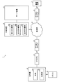
- FIG. 1 is an explanatory diagram showing an example of the air conditioning system of the present embodiment.
- FIG. 2 is a block diagram showing an example of the configuration of the adapter.
- FIG. 3 is an explanatory diagram showing an example of writing and reading in each storage area of the model memory.
- FIG. 4 is an explanatory diagram showing an example of the data structure of the divided data in the update control program.
- FIG. 5 is a block diagram showing an example of the configuration of the server device.
- FIG. 6 is a block diagram showing an example of the configuration of the control unit of the indoor unit.
- FIG. 7 is a flowchart showing an example of the processing operation of the CPU in the adapter related to the update switching processing.
- FIG. 8 is a flowchart showing an example of the processing operation of the CPU in the adapter relating to the first update processing.
- FIG. 9 is a flowchart showing an example of the processing operation of the CPU in the adapter relating to the second update processing.
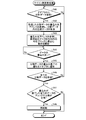
- FIG. 10 is a flowchart showing an example of the processing operation of the indoor unit microcomputer in the control unit related to the microcomputer side updating process.
- FIG. 1 is an explanatory diagram showing an example of the air conditioning system 1 of the present embodiment.
- the air conditioning system 1 illustrated in FIG. 1 includes an indoor unit 2, an adapter 3, a router 4, a server device 5, a relay device 6, a communication terminal 7, and a communication network 8.
- the indoor unit 2 is, for example, a part of an air conditioner that is placed indoors and heats or cools the indoor air.
- the user of the indoor unit 2 can remotely operate the indoor unit 2 by operating the remote controller 9.
- the indoor unit 2 has a main body 2A and a control unit 2B that controls the main body 2A.
- the main body 2A is provided with an indoor fan and an indoor heat exchanger, and the room air that has exchanged heat with the refrigerant in the indoor heat exchanger is blown out from the main body 2A to perform heating, cooling, dehumidification, etc. of the room. Be seen.
- the outdoor unit (not shown) is equipped with an outdoor fan and a compressor.
- the communication terminal 7 is a terminal device such as a user's smartphone.
- the adapter 3 has a communication function that connects the indoor unit 2 and the router 4 by wireless communication, and a control function that controls the indoor unit 2 by AI (Artificial Intelligence).
- the adapter 3 is arranged for each indoor unit 2.
- the router 4 is an access point device that connects the adapter 3 and the communication network 8 by wireless communication using, for example, a WLAN (Wireless Local Area Network).
- the communication network 8 is, for example, a communication network such as the Internet.
- the server device 5 has a function of generating an AI learning model for controlling the indoor unit 2, a database for storing operation history data, and the like.
- the server device 5 is arranged in, for example, a data center.
- the relay device 6 has a function of connecting to the communication network 8 by communication and also connecting to the server device 5 by communication.
- the relay device 6 transmits from the adapter 3 to the server device 5 the operation history data and the like used for generating or updating the learning model applied to the indoor unit 2 via the communication network 8.
- the relay device 6 also transmits the learning model generated or updated by the server device 5 to the adapter 3 via the communication network 8.
- the relay device 6 is arranged, for example, in a data center or the like.
- the relay device 6 has a first relay section 6A, a second relay section 6B, and a third relay section 6C.
- the first relay unit 6A transmits various data related to AI control between the adapter 3 and the server device 5.
- the first relay unit 6A transmits the operation history data and the like used for generating or updating the learning model received from the adapter 3 to the server device 5 via the communication network 8, and at the same time, the learning model generated or updated by the server device 5 is transmitted. Is transmitted to the adapter 3 via the communication network 8.
- the second relay unit 6B acquires the operating conditions of the indoor unit 2 (the operating mode such as cooling/heating and the set temperature) set by the user using the communication terminal 7 from the place where the indoor unit 2 uses. Send to.
- the third relay unit 6C acquires external data such as a weather forecast from the communication network 8 such as the Internet, and transmits the acquired external data to the server device 5, for example.
- the third relay unit 6C also transmits external data to the adapter 3 via the communication network 8.
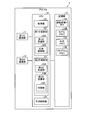
- FIG. 2 is a block diagram showing an example of the configuration of the adapter 3.
- the adapter 3 illustrated in FIG. 2 includes a first communication unit 11, a second communication unit 12, a storage unit 13, and a CPU (Central Processing Unit) 14.
- the first communication unit 11 is a communication IF (Interface) such as a UART (Universal Asynchronous Receiver Transmitter) that is communicatively connected to the control unit 2B in the indoor unit 2.
- the second communication unit 12 is a communication unit such as a communication interface such as a WLAN, which is communicatively connected to the router 4.
- the storage unit 13 has, for example, a ROM (Read Only Memory) and a RAM (Random Access Memory), and stores various information such as data and programs.
- the CPU 14 controls the entire adapter 3.
- the storage unit 13 in the adapter 3 illustrated in FIG. 2 includes a driving history memory 13A that temporarily stores the driving history data acquired from the indoor unit 2, a model memory 13B that stores the learning model acquired from the server device 5, and It has an external memory 13C for storing external data and a program memory 13D for storing the update control program acquired from the server device 5.
- the update control program is a program that updates the control program of the air conditioning system 1 from the server device 5, for example, the firmware of the control unit 2B that controls the indoor unit 2.
- the model memory 13B has a plurality of storage areas 130 such as a first area 130A, a second area 130B, and a third area 130C, for example.
- the status of each storage area 130 includes, for example, a state in which a written learning model can be read (hereinafter, simply referred to as reading), a state in which a new learning model is being written (hereinafter, simply referred to as writing), and , There is a state in which the learning model has been written, other than the reading state.
- the CPU 14 has an acquisition unit 21, a first updating unit 22, a second updating unit 23, and a prediction control unit 24.
- the acquisition unit 21 acquires the operation history data from the indoor unit 2 at a predetermined cycle, for example, at an acquisition timing of every 5 minutes.
- the acquisition unit 21 stores the operation history data acquired in the 5-minute cycle in the operation history memory 13A.
- the acquisition unit 21 transmits the driving history data stored in the driving history memory 13A to the server device 5 via the communication network 8.
- the first updating unit 22 receives the learning model from the server device 5 via the communication network 8 and stores the received learning model in the model memory 13B by the first updating method.
- the first updating unit 22 has a first receiving unit 22A and a switching control unit 22B.
- the first receiving unit 22A receives a new learning model from the server device 5 via the communication network 8 and stores the received new learning model in the model memory 13B.
- the switching control unit 22B writes the new learning model in the storage area 130 and switches the status of the storage area 130 in which the new learning model is being written to being read.
- the first updating method is a method of overwriting and storing the new learning model received by the first receiving unit 22A in the written storage area 130.
- FIG. 3 is an explanatory diagram showing an example of writing and reading in each storage area 130 of the model memory 13B.
- a learning model being read (current model) in the first area 130A and a written learning model (previous model) in the third area 130C are stored,
- a new learning model (latest model) is written in the area 130B of No. 2
- the situation A2 is a state where the writing is completed.
- the latest learning model is stored in the second area 130B. Therefore, the control of the air conditioning system 1 by the learning model is performed by the latest learning model (current model) stored in the second area 130B (the second area 130B is being read).
- the learning model stored in the first area 130A is the previous learning model (previous model).
- the learning model stored in the third area 130C is the learning model before the previous time (the model before the previous time).
- the first receiving unit 22A receives the latest learning model (current model) except for the second area 130B which is being read, and the reception time is the first.
- the new learning model (latest model) and the reception time are overwritten in the written third area 130C in which the old learning model (previous model) is written.
- the switching control unit 22B brings the third area 130C into the writing state (situation B1).
- the status B2 is set. That is, the control of the air conditioning system 1 by the learning model is performed by the latest learning model (current model) stored in the third region 130C (the third region 130C is being read).
- the learning model stored in the second area 130B is the previous learning model (previous model).
- the learning model stored in the first area 130A becomes a learning model before the previous time (previous time model).
- the first receiving unit 22A receives a new learning model from the server device 5 in the state of situation B2, the first receiving unit 22A excludes the third area 130C from which the learning model (current model) is being read, and the reception time Is written in the written first area 130A in which the oldest learning model (previous model) is written, by overwriting the new learning model (latest model) and the reception time.
- the switching control unit 22B brings the first area 130A into the writing state (situation C1).
- the status C2 is set. That is, the control of the air conditioning system 1 by the learning model is performed by the latest learning model (current model) stored in the first area 130A (the first area 130A is being read).
- the learning model stored in the third area 130C is the previous learning model (previous model).
- the learning model stored in the second area 130B is the learning model before the previous time (the model before the previous time). Then, each time the new learning model is received, the switching control unit 22B and the situation are sequentially switched.
- the second update unit 23 receives the update control program for the control unit 2B of the indoor unit 2 from the server device 5, the second update unit 23 uses the second update method different from the first update method for the control unit 2B. Rewrite the control program of.
- the second updating unit 23 has a second receiving unit 23A and a second transmitting unit 23B.
- the second receiving unit 23A stores the update control program received from the server device 5 in the program memory 13D.
- the second transmission unit 23B transmits the update control program stored in the program memory 13D to the control unit 2B of the indoor unit 2.
- FIG. 4 is an explanatory diagram showing an example of the data structure of the divided data 40 in the update control program.
- the update control program is composed of a plurality of pieces of divided data 40 divided by a predetermined data length.
- the divided data 40 has a data length 41, a write destination address 42, and compressed data 43.
- the data length 41 is information (2 bytes) of the data length up to the write destination address 42 and the compressed data 43.
- the write destination address 42 is address information (3 bytes) when writing to the block 52A in the ROM 52 in the control unit 2B of the indoor unit 2, which is the target device.
- the compressed data 43 is n-byte data compressed by a predetermined method.
- the capacity of the compressed data 43 after decompression corresponds to the storage capacity of 1 Kbyte (1024 bytes) of one block in the ROM 52, for example.
- the data length 41 and the write destination address 42 are not compressed.
- the second receiving unit 23A receives the divided data 40 in the update control program from the server device 5 in units of divided data.
- the received divided data 40 is sequentially stored in the program memory 13D.
- the second transmission unit 23B refers to the data length 41 in the divided data 40 of the divided data 40 stored in the program memory 13B, extracts the data for the data length from the update control program, and extracts the divided data 40.
- the data is sequentially transmitted to the control unit 2B of the indoor unit 2. After receiving the divided data 40, the indoor unit 2 decompresses the divided data 40 and writes the decompressed divided data 40 in the block 52A.
- the indoor unit 2 notifies the adapter 3 of the completion of writing the divided data 40 after writing the divided data in the block 52A.
- the second transmission unit 23B in the adapter 3 detects the completion of writing the transmitted divided data 40 from the indoor unit 2 to the block 52A
- the divided data 40 not transmitted to the indoor unit 2 is stored in the program memory 13D. It has a determination unit 23C that determines whether or not there is.
- the second transmitting unit 23B transmits the untransmitted divided data 40 to the control unit 2B in the indoor unit 2.
- the prediction control unit 24 controls the control unit 2B in the indoor unit 2 based on the learning model.
- the prediction control unit 24 has exemplified the case where the control unit 2B in the indoor unit 2 is controlled based on the learning model.
- the prediction control unit 24 is based on the learning model and the main body of the indoor unit 2 is controlled. 2A may be controlled directly.
- the prediction control unit 24 transmits the control mode based on the learning model to the control unit 2B. That is, the prediction control unit 24 may indirectly control the main body 2A via the control unit 2B, and can be appropriately changed.
- the CPU 14 in the adapter 3 executes the first update processing when detecting the download request for the learning model, and executes the update switching processing for executing the second update processing when detecting the download request for the update control program. Execute.
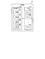
- FIG. 5 is a block diagram showing an example of the configuration of the server device 5.
- the server device 5 illustrated in FIG. 5 includes a communication unit 31, a storage unit 32, and a CPU 33.
- the communication unit 31 is a communication IF that is communicatively connected to the relay device 6.
- the storage unit 32 has, for example, an HDD (Hard Disk Drive), a ROM, a RAM, and the like, and stores various information such as data and programs.
- the CPU 33 controls the server device 5 as a whole.
- the storage unit 32 in the server device 5 shown in FIG. 5 has a data memory 32A, a model storage unit 32B, and a program storage unit 32C.
- the data memory 32A stores the operation history data and the like received from each adapter 3.
- the model storage unit 32B stores the learning model generated or updated by the server device 5.
- the program storage unit 32C stores a plurality of pieces of divided data 40 in the update control program generated or updated by the server device 5 in units of divided data 40.
- the CPU 33 in the server device 5 has a model learning unit 33A, a receiving unit 33B, and a transmitting unit 33C.
- the model learning unit 33A receives the operation history data for 48 hours from each adapter 3 via the router 4, the communication network 8 and the relay device 6 by connecting to each adapter 3 of the plurality of indoor units 2. Then, the model learning unit 33A learns by using the driving history data for 48 hours stored in the data memory 32A from each adapter 3, and generates or updates the learning model of each indoor unit 2 based on the learning result. To do.
- the learning model for example, the sensible temperature after 5 minutes for the user in the room is predicted according to the operating condition of the air conditioner in each home, and the sensible temperature setting for controlling the air conditioner according to the predicted sensible temperature is set. There is a predictive model.
- the model learning unit 33A generates or updates the learning model corresponding to the adapter 3 based on the operation history data for 48 hours for each adapter 3 stored in the data memory 32A, and the generated or updated learning model is stored in the model storage unit.
- the transmission unit 33C transmits the learning model generated or updated by the model learning unit 33A to the adapter 3 via the relay device 6, the communication network 8 and the router 4.
- the transmission unit 33C also transmits the divided data 40 of the update control program stored in the program storage unit 32C to the adapter 3 via the relay device 6, the communication network 8 and the router 4.
- FIG. 6 is a block diagram showing an example of the configuration of the control unit 2B of the indoor unit 2.
- the control unit 2B shown in FIG. 6 has an indoor unit microcomputer 51 and a ROM (Read Only Memory) 52.
- the ROM 52 has a plurality of blocks 52A, and the storage capacity of each block 52A is 1024 bytes.
- the write destination address 42 of the divided data 40 is an address for identifying the block 52A in the ROM 52.
- the indoor unit microcomputer 51 has a reception unit 51A, a decompression unit 51B, an update unit 51C, and an execution unit 51D.
- the receiver 51A receives the divided data 40 of the update control program from the adapter 3.
- the decompression unit 51B receives the divided data 40, it refers to the write destination address 42 in the divided data 40 and decompresses the compressed data 43 in the divided data 40.
- the updating unit 51C refers to the write destination address 42 in the divided data 40, and overwrites the decompressed data on the block 52A in the ROM 52 corresponding to the write destination address 42.
- the execution unit 51D restarts the indoor unit microcomputer 51 when the overwriting of the block 52A in the ROM 52 of all the divided data 40 of the update control program is completed and all the overwritten data are normal. To do. Whether or not the data is normal is determined by, for example, whether or not the checksum value of the entire overwritten update control program and the value added as data to the update control program match.
- the indoor unit microcomputer 51 temporarily stops the indoor unit 2 when executing the restart.
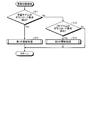
- FIG. 7 is a flowchart showing an example of the processing operation of the CPU 14 in the adapter 3 relating to the update switching processing.
- the first updating unit 22 in the CPU 14 in the adapter 3 determines whether a learning model download request from the server device 5 has been detected (step S11).
- the first update unit 22 executes the first update process shown in FIG. 8 (step S12) and ends the process operation shown in FIG. .
- the first update process is a process for updating the learning model using the first update method.
- the second updating unit 23 in the CPU 14 requests the update control program from the server device 5. It is determined whether or not is detected (step S13). When the download request for the update control program is detected (Yes in step S13), the second update unit 23 executes the second update process shown in FIG. 9 (step S14) and executes the process operation shown in FIG. finish.
- the second update process is a process for updating the control program of the control unit 2B of the indoor unit 2 using the second update method. If the download request for the update control program has not been detected (No in step S13), the CPU 14 ends the processing operation shown in FIG.
- the adapter 3 when the adapter 3 detects the download request for the learning model from the server device 5, the adapter 3 updates the learning model by the first updating method and also downloads the update control program from the server device 5. When it detects, the control program in the control unit 2B of the indoor unit 2 is updated by the second updating method.
- the adapter 3 updates the learning model and the control program in the control unit 2B by a different method, so that processing other than the processing originally required by the adapter (for example, data transmission/reception, learning model storage) is performed (In other words, without performing "useless processing"), the divided data 40 is sequentially transmitted to the indoor unit 2 and the control unit 2B side of the indoor unit 2 executes the overwriting of the divided data 40, thus reducing the load on the adapter 3. it can.
- processing other than the processing originally required by the adapter for example, data transmission/reception, learning model storage
- the divided data 40 is sequentially transmitted to the indoor unit 2 and the control unit 2B side of the indoor unit 2 executes the overwriting of the divided data 40, thus reducing the load on the adapter 3. it can.
- FIG. 8 is a flowchart showing an example of the processing operation of the CPU 14 in the adapter 3 related to the first update processing.
- the first updating unit 22 in the CPU 14 determines whether the latest learning model in the storage area 130 is being read (step S21). When the latest learning model in the storage area 130 is being read (step S21, Yes), the first receiving unit 22A in the first updating unit 22 starts downloading a new learning model from the server device 5. (Step S22).
- the switching control unit 22B in the first updating unit 22 writes the new learning model downloaded by the first receiving unit 22A into the writing storage area 130 (step S23), and updates the latest reading of the reading storage area 130. It is determined whether the control based on the learning model (current model) has been completed (step S24).
- the control based on the latest learning model (current model) of the storage area 130 being read means the recommended operation for the control unit 2B in the indoor unit 2 based on the learning model (current model) of the storage area 130. It is the control provided.
- the switching control unit 22B sets the status of the storage area 130 in which the new learning model is written to “latest”. Of the learning model stored in the storage area 130”, the status of the storage area 130 from which the learning model was read is switched to “storage area 130 storing the previous learning model”, and the status of the written storage area 130 is changed. The status is switched to "the storage area 130 in which the learning model of the previous learning process is stored" (step S25), and the processing operation shown in FIG. 8 is ended.
- the first receiving unit 22A starts downloading a new learning model from the server device 5 (step S26).
- the switching control unit 22B writes the new learning model downloaded by the first receiving unit 22A in the storage area 130 (step S27), and switches the status of the storage area 130 in which the new learning model is written in step S25. Go to processing.
- the first updating unit 22 determines whether the control is completed. , And returns to the process of step S24.
- the adapter 3 writes the new learning model received from the server device 5 to the written storage area 130 having the oldest reception time among the plurality of storage areas 130 excluding the storage area 130 being read. Write the new learning model and the reception time in. As a result, the adapter 3 can overwrite the new learning model in the model memory 13B while using the learning model being read. Therefore, even when the learning model is updated, the situation in which the indoor unit 2 is stopped can be avoided.
- FIG. 9 is a flowchart showing an example of the processing operation of the CPU 14 in the adapter 3 related to the second update processing.
- the second receiving unit 23A in the second updating unit 23 of the CPU 14 starts downloading the plurality of pieces of divided data 40 of the update control program from the server device 5 (step S31), and the divided data 40 is programmed by the program. It is stored in the memory 13D (step S32).
- the second updating unit 23 determines whether or not the program update timing has been detected (step S33).
- the program update timing is, for example, whether or not the update control program can be updated on the control unit 2B side of the indoor unit 2, for example, the update time of the update control program designated by the user of the indoor unit 2 ( It is whether or not it is the absence time of the user).
- the second transmission unit 23B in the second update unit 23 reads the untransmitted division data 40 from the program memory 13D (step S34), and the read division is performed.
- the data length 41 of the data 40 is referred to, data corresponding to the data length is extracted from the update control program, and the divided data 40 is transmitted to the control unit 2B of the indoor unit 2 (step S35). That is, the adapter 3 sequentially processes the divided data 40 to the indoor unit 2 without performing processing (in other words, "useless processing") other than the processing originally required by the adapter (for example, data transmission/reception, learning model storage). Since it can be sent, the processing load on the adapter is reduced.
- the second transmission unit 23B determines whether or not the notification of the completion of writing the transmitted divided data 40 from the control unit 2B is detected (step S36).
- the determination unit 23C detects the write completion notification of the transmitted divided data 40 from the control unit 2B (Yes in step S36)
- the determination unit 23C determines whether or not there is the untransmitted divided data 40 in the program memory 13D. Yes (step S37).
- the second update unit 23 completes the transmission of all the divided data 40 in the update control program to the control unit 2B. It is determined that the operation is completed, and the processing operation shown in FIG. 9 ends.
- step S33 When the program update timing is not detected (No in step S33), the second updating unit 23 returns to the process of step S33 to determine whether the program update timing is detected.
- step S36 When the second updating unit 23 does not detect the notification of the writing completion of the transmitted divided data 40 from the control unit 2B (No in step S36), the writing completion of the transmitted divided data 40 from the control unit 2B is completed. The process returns to step S36 to determine whether the notification is detected.
- step S37 If there is untransmitted divided data 40 in the program memory 13D (step S37, Yes), the second transmitting unit 23B returns to the process of step S34 to read the untransmitted divided data 40 from the program memory 13D.
- the adapter 3 sequentially receives the plurality of pieces of divided data 40 in the update control program from the server device 5 and stores them in the program memory 13D.
- the adapter 3 sequentially transmits the untransmitted divided data 40 in the update control program stored in the program memory 13D to the control unit 2B in the indoor unit 2.
- the adapter 3 can sequentially transmit the divided data 40 in the large-capacity update control program to the control unit 2B without performing wasteful processing, so that the processing load of the adapter is reduced.
- FIG. 10 is a flowchart showing an example of the processing operation of the indoor unit microcomputer 51 in the control unit 2B related to the microcomputer side updating process.
- the receiving unit 51A in the indoor unit microcomputer 51 determines whether or not the plurality of divided data 40 has been received from the adapter 3 (step S41).
- the decompression unit 51B in the indoor unit microcomputer 51 receives a plurality of pieces of divided data 40 from the adapter 3 (step S41, Yes)
- the decompression unit 51B refers to the write destination address 42 of the received divided data 40, Only the compressed data 43 is decompressed (step S42).
- the updating unit 51C in the indoor unit microcomputer 51 starts the operation of writing the decompressed data in the block 52A in the ROM 52 of the write destination address 42 (step S43), and determines whether or not the writing of the data in the block 52A is completed. It is determined whether or not (step S44).
- the indoor unit microcomputer 51 can write the decompressed data in the block 52A by referring to the write destination address 42 of the divided data 40. As a result, it is possible to reduce the time required for writing and suppress deterioration of the ROM 52 due to useless writing.
- the updating unit 51C When the writing of the data in the block 52A is completed (Yes in step S44), the updating unit 51C notifies the adapter 3 of the completion of writing the divided data 40 (step S45). The update unit 51C determines whether or not all the divided data 40 in the update control program have been received (step S46). When the update unit 51C receives all the divided data 40 in the update control program (Yes in step S46), the update unit 51C determines whether all the written data are normal based on the checksum value. (Step S47).
- the execution unit 51D in the indoor unit microcomputer 51 executes a restart of the indoor unit microcomputer 51 (Step S48) when all the written data are normal (Step S47, Yes), and the processing operation shown in FIG. To finish.
- step S41 If the division data 40 is not received from the adapter 3 (step S41, No), the reception unit 51A returns to the process of step S41 to determine whether or not the division data 40 is received. When the data writing is not completed (No in step S44), the updating unit 51C returns to the process of step S44 in order to continue monitoring whether or not the data writing started in step S43 is completed.
- step S46, No If not all the divided data 40 have been received (step S46, No), the updating unit 51C returns to the processing of step S41 to determine whether or not the divided data 40 has been received from the adapter 3. When all the data that have been written are not normal (step S47, No), the updating unit 51C notifies the user that writing is not possible and ends the processing operation shown in FIG.
- the control unit 2B in the indoor unit 2 receives the divided data 40 from the adapter 3, decompresses the compressed data 43 in the received divided data 40, and corresponds to the write destination address 42 of the divided data 40.
- the decompressed data is written in the block 52A.
- the control unit 2B writes all the decompressed data of all the divided data 40 in the update control program into the block 52A, and then rewrites the indoor unit 2 when all the written data are normal. to start.
- the control unit 2B in the indoor unit 2 can update the update control program while reducing the time required for writing and suppressing deterioration of the ROM 52 due to useless writing.
- the adapter 3 of this embodiment updates the learning model by the first updating method and updates the program of the control unit 2B by the second updating method.
- the update method differs between the learning model update and the program update, so that the load on the adapter 3 can be reduced.
- the update control program for the air conditioning system 1 for example, the update control program for updating the firmware of the indoor unit 2 is illustrated.
- the update control program for updating the firmware of the adapter 3 the indoor An update control program for updating the firmware of the control unit 2B that controls the machine 2 may be used, and can be appropriately changed.
- the adapter 3 When the adapter 3 receives a new learning model from the server device 5, the adapter 3 overwrites the received new learning model in the written storage area 130.
- the learning model may be deleted when the written storage area 130 is switched to the written storage area 130, and can be changed as appropriate.
- the storage area 130 in the model memory 13B in the adapter 3 is composed of the first area 130A, the second area 130B, and the third area 130C is illustrated.
- the number of storage areas 130 is not limited to three, and for example, two or more storage areas 130 may be used and can be appropriately changed.
- the indoor unit microcomputer 51 when the indoor unit microcomputer 51 receives the divided data from the adapter 3, it decompresses the divided data, compares the decompressed data with the data stored in the write target block 52A, and if the data is the same, Instead of writing the data of the block 52A, the data after the next decompression may be compared with the data stored in the write target block 52A. As a result, the life of the indoor unit microcomputer 51 can be extended by reducing the number of unnecessary writings. Moreover, the adapter 3 does not need to confirm whether it is necessary to write in each block 52A for each divided data 40.
- each constituent element of each part illustrated does not necessarily have to be physically configured as illustrated. That is, the specific form of the distribution/integration of each part is not limited to the one shown in the figure, and all or part of them may be functionally or physically distributed/integrated in arbitrary units according to various loads and usage conditions. Can be configured.
- each device may be implemented in whole or in part on a CPU (Central Processing Unit) (or a microcomputer such as MPU (Micro Processing Unit) and MCU (Micro Controller Unit)). It may be executed. Further, various processing functions may be executed in whole or in part on a program analyzed by a CPU (or a microcomputer such as MPU or MCU) or on hardware by a wired logic. Needless to say.
- a CPU Central Processing Unit
- MPU Micro Processing Unit
- MCU Micro Controller Unit
- Air Conditioning System 2 Indoor Unit 2A Main Body 2B Control Unit 3 Adapter 5 Server Device 13B Model Memory 13D Program Memory 22 First Update Unit 22A First Receiver 22B Switch Control Unit 23 Second Update Unit 23A Second Reception Part 23B Second transmitter 23C Judgment unit
Landscapes
- Engineering & Computer Science (AREA)
- Signal Processing (AREA)
- Chemical & Material Sciences (AREA)
- Combustion & Propulsion (AREA)
- Mechanical Engineering (AREA)
- General Engineering & Computer Science (AREA)
- Physics & Mathematics (AREA)
- Fuzzy Systems (AREA)
- Mathematical Physics (AREA)
- Human Computer Interaction (AREA)
- Stored Programmes (AREA)
- Air Conditioning Control Device (AREA)
Abstract
Description
2 室内機
2A 本体
2B 制御部
3 アダプタ
5 サーバ装置
13B モデルメモリ
13D プログラムメモリ
22 第1の更新部
22A 第1の受信部
22B 切替制御部
23 第2の更新部
23A 第2の受信部
23B 第2の送信部
23C 判定部
Claims (4)
- 空気調和機と、前記空気調和機と外部サーバ装置を接続するアダプタとを備えた空気調和システムにおいて、
前記アダプタは、
前記外部サーバ装置から前記空気調和機の制御部に推奨動作を提供する新たな学習モデルを受信した場合に、当該学習モデルを第1の更新方法で更新する第1の更新部と、
前記外部サーバ装置から前記空気調和機の制御プログラムを更新する更新用制御プログラムを受信した場合に、当該更新用制御プログラムを、前記第1の更新方法と異なる第2の更新方法で更新する第2の更新部と
を有することを特徴とする空気調和システム。 - 前記第1の更新部は、
新たな学習モデルを記憶する第1の領域と、現在の学習モデルを記憶する第2の領域とを含む第1の記憶部と、
前記外部サーバ装置から前記新たな学習モデルを検出した場合に、当該新たな学習モデルを前記第1の領域に記憶し、当該第1の領域を第2の領域に切替える切替制御部と
を有し、
前記第2の領域に切替えられた前記新たな学習モデルを用いて前記空気調和機に前記推奨動作を提供することを特徴とする請求項1に記載の空気調和システム。 - 前記更新用制御プログラムは、所定のデータ長で分割された複数の分割データで形成され、前記分割データには、前記分割データを前記室内機へ書き込む際の書き込み先を示す書き込み先アドレスが付加され、
前記第2の更新部は、
前記サーバ装置から受信した前記更新用制御プログラムを記憶する第2の記憶部と、
前記所定のデータ長単位の前記更新用制御プログラムを、前記書き込み先アドレスを参照して前記室内機に順次送信する送信部と
を有することを特徴とする請求項1又は2に記載の空気調和システム。 - 前記分割データは、所定の方法で圧縮される一方、前記書き込み先アドレスは圧縮されないことを特徴とする請求項3に記載の空気調和システム。
Priority Applications (4)
| Application Number | Priority Date | Filing Date | Title |
|---|---|---|---|
| CN201980087588.XA CN113260819B (zh) | 2019-01-16 | 2019-12-19 | 空调系统 |
| EP19910625.3A EP3913294B1 (en) | 2019-01-16 | 2019-12-19 | Air conditioning system |
| US17/421,876 US11828479B2 (en) | 2019-01-16 | 2019-12-19 | Server based air conditioning system adaptor for updating control program |
| AU2019423025A AU2019423025B2 (en) | 2019-01-16 | 2019-12-19 | Air conditioning system |
Applications Claiming Priority (2)
| Application Number | Priority Date | Filing Date | Title |
|---|---|---|---|
| JP2019-005445 | 2019-01-16 | ||
| JP2019005445A JP6699764B1 (ja) | 2019-01-16 | 2019-01-16 | 空気調和システム |
Publications (1)
| Publication Number | Publication Date |
|---|---|
| WO2020149093A1 true WO2020149093A1 (ja) | 2020-07-23 |
Family
ID=70776095
Family Applications (1)
| Application Number | Title | Priority Date | Filing Date |
|---|---|---|---|
| PCT/JP2019/049791 Ceased WO2020149093A1 (ja) | 2019-01-16 | 2019-12-19 | 空気調和システム |
Country Status (6)
| Country | Link |
|---|---|
| US (1) | US11828479B2 (ja) |
| EP (1) | EP3913294B1 (ja) |
| JP (1) | JP6699764B1 (ja) |
| CN (1) | CN113260819B (ja) |
| AU (1) | AU2019423025B2 (ja) |
| WO (1) | WO2020149093A1 (ja) |
Families Citing this family (3)
| Publication number | Priority date | Publication date | Assignee | Title |
|---|---|---|---|---|
| US20220189476A1 (en) * | 2019-03-22 | 2022-06-16 | Mitsubishi Heavy Industries Thermal Systems, Ltd. | Control device, apparatus control system, control method, and program |
| CN115843328A (zh) * | 2020-06-08 | 2023-03-24 | 三菱电机株式会社 | 制冷循环装置 |
| JP7686504B2 (ja) * | 2021-09-01 | 2025-06-02 | 大阪瓦斯株式会社 | 通信システム |
Citations (7)
| Publication number | Priority date | Publication date | Assignee | Title |
|---|---|---|---|---|
| JP2008190853A (ja) | 2007-02-02 | 2008-08-21 | Samsung Electronics Co Ltd | 空気調和機システムおよびそのプログラム更新方法 |
| JP2015117933A (ja) | 2013-04-24 | 2015-06-25 | 積水化学工業株式会社 | 空調システム及び建物 |
| JP2018005894A (ja) * | 2016-06-23 | 2018-01-11 | 住友電気工業株式会社 | プログラム配信システム、サーバ、プログラム配信方法、およびコンピュータプログラム |
| JP2018092288A (ja) * | 2016-12-01 | 2018-06-14 | 日立ジョンソンコントロールズ空調株式会社 | プロトコル変換装置、プロトコル変換システム、および、設備機器 |
| US20180283723A1 (en) * | 2017-03-30 | 2018-10-04 | Samsung Electronics Co., Ltd. | Data learning server and method for generating and using learning model thereof |
| JP2019008645A (ja) * | 2017-06-27 | 2019-01-17 | ソフトバンク株式会社 | サーバ装置、サーバ装置がIoTデバイスと通信する方法、コンピュータプログラム、通信システムおよびIoTデバイス |
| JP2019074279A (ja) * | 2017-10-18 | 2019-05-16 | 株式会社富士通ゼネラル | 空気調和機 |
Family Cites Families (29)
| Publication number | Priority date | Publication date | Assignee | Title |
|---|---|---|---|---|
| CA2357382A1 (en) * | 2001-09-17 | 2003-03-17 | Soma Networks, Inc. | Software update method, apparatus and system |
| US20050257206A1 (en) * | 2004-05-14 | 2005-11-17 | Semerdzhiev Krasimir P | Pair-update mechanism for update module |
| JP2006268172A (ja) * | 2005-03-22 | 2006-10-05 | Nec Corp | サーバシステムおよびオンラインソフトウェア更新方法 |
| JP4704252B2 (ja) * | 2006-03-14 | 2011-06-15 | 富士通株式会社 | ネットワークシステムのブロードキャスト処理方法及びネットワークシステム |
| JP2009133549A (ja) | 2007-11-30 | 2009-06-18 | Hitachi Appliances Inc | 空気調和機用の通信アダプタ及び空気調和機の制御プログラム更新システム |
| DK2294487T3 (da) * | 2008-07-03 | 2012-07-09 | Belimo Holding Ag | Aktuator til varme-, ventilations- og luftkonditioneringssystemer samt fremgangsmåde til betjening af aktuatoren |
| US9256230B2 (en) | 2010-11-19 | 2016-02-09 | Google Inc. | HVAC schedule establishment in an intelligent, network-connected thermostat |
| EP2590100A1 (en) * | 2011-11-04 | 2013-05-08 | British Telecommunications Public Limited Company | Method and apparatus for securing a computer |
| US8594850B1 (en) * | 2012-09-30 | 2013-11-26 | Nest Labs, Inc. | Updating control software on a network-connected HVAC controller |
| CN103873946A (zh) * | 2014-04-04 | 2014-06-18 | 珠海迈科电子科技有限公司 | 一种基于android的智能电视分页显示方法和装置 |
| TWI546506B (zh) * | 2014-12-04 | 2016-08-21 | 台達電子工業股份有限公司 | 環境舒適度控制系統及其控制方法 |
| JP2016143318A (ja) | 2015-02-04 | 2016-08-08 | 三菱電機株式会社 | プログラム更新装置、プログラム更新システム、家電機器、通信アダプタ、コントローラ、プログラム更新方法、および、プログラム |
| CN106471789B (zh) * | 2015-09-24 | 2021-02-02 | Oppo广东移动通信有限公司 | 适配器升级的方法、装置和系统 |
| CN106680698B (zh) * | 2015-11-11 | 2023-08-18 | 上海复旦微电子集团股份有限公司 | 一种fpga测试用的多工位快速配置装置及其配置方法 |
| WO2017149821A1 (ja) | 2016-03-02 | 2017-09-08 | 住友電気工業株式会社 | 制御装置、プログラム更新方法、およびコンピュータプログラム |
| WO2017149826A1 (ja) | 2016-03-02 | 2017-09-08 | 住友電気工業株式会社 | 制御装置、プログラム配信方法、およびコンピュータプログラム |
| JP6323480B2 (ja) | 2016-03-02 | 2018-05-16 | 住友電気工業株式会社 | プログラム更新システム、プログラム更新方法及びコンピュータプログラム |
| WO2017199331A1 (ja) | 2016-05-17 | 2017-11-23 | 三菱電機株式会社 | 空気調和機システム、書き換え制御方法及び書き換え制御プログラム |
| US20190129710A1 (en) | 2016-06-02 | 2019-05-02 | Sumitomo Electric Industries, Ltd. | Control apparatus, method for determining whether or not a control program is updatable, and computer program |
| CN106339242A (zh) * | 2016-07-26 | 2017-01-18 | 深圳市英威腾交通技术有限公司 | 一种电力机车控制设备的软件更新方法和系统 |
| KR20180071031A (ko) * | 2016-12-19 | 2018-06-27 | 엘지전자 주식회사 | 공기조화기 및 그 제어방법 |
| US10803392B1 (en) * | 2017-03-10 | 2020-10-13 | Amazon Technologies, Inc | Deploying machine learning-based models |
| KR102393418B1 (ko) | 2017-03-30 | 2022-05-03 | 삼성전자주식회사 | 데이터 학습 서버 및 이의 학습 모델 생성 및 이용 방법 |
| US10237131B2 (en) * | 2017-06-14 | 2019-03-19 | Noritz Corporation | Communication adapter and program update method for communication adapter |
| WO2019105572A1 (en) * | 2017-12-01 | 2019-06-06 | Telefonaktiebolaget Lm Ericsson (Publ) | Selecting learning model |
| JP6985518B2 (ja) * | 2017-12-22 | 2021-12-22 | 華為技術有限公司Huawei Technologies Co., Ltd. | パーソナライズされた推奨を生成するために適合されたクライアント、サーバ、およびクライアント−サーバシステム |
| EP3734519A4 (en) * | 2017-12-26 | 2021-09-15 | Aising Ltd. | PROCESS FOR GENERATING A UNIVERSAL LEARNED MODEL |
| US20200050935A1 (en) * | 2018-08-10 | 2020-02-13 | Nvidia Corporation | Deep learning model execution using tagged data |
| US11605011B2 (en) * | 2019-05-31 | 2023-03-14 | Johnson Controls Tyco IP Holdings LLP | Analysis system with machine learning based interpretation |
-
2019
- 2019-01-16 JP JP2019005445A patent/JP6699764B1/ja active Active
- 2019-12-19 EP EP19910625.3A patent/EP3913294B1/en active Active
- 2019-12-19 WO PCT/JP2019/049791 patent/WO2020149093A1/ja not_active Ceased
- 2019-12-19 CN CN201980087588.XA patent/CN113260819B/zh active Active
- 2019-12-19 AU AU2019423025A patent/AU2019423025B2/en active Active
- 2019-12-19 US US17/421,876 patent/US11828479B2/en active Active
Patent Citations (7)
| Publication number | Priority date | Publication date | Assignee | Title |
|---|---|---|---|---|
| JP2008190853A (ja) | 2007-02-02 | 2008-08-21 | Samsung Electronics Co Ltd | 空気調和機システムおよびそのプログラム更新方法 |
| JP2015117933A (ja) | 2013-04-24 | 2015-06-25 | 積水化学工業株式会社 | 空調システム及び建物 |
| JP2018005894A (ja) * | 2016-06-23 | 2018-01-11 | 住友電気工業株式会社 | プログラム配信システム、サーバ、プログラム配信方法、およびコンピュータプログラム |
| JP2018092288A (ja) * | 2016-12-01 | 2018-06-14 | 日立ジョンソンコントロールズ空調株式会社 | プロトコル変換装置、プロトコル変換システム、および、設備機器 |
| US20180283723A1 (en) * | 2017-03-30 | 2018-10-04 | Samsung Electronics Co., Ltd. | Data learning server and method for generating and using learning model thereof |
| JP2019008645A (ja) * | 2017-06-27 | 2019-01-17 | ソフトバンク株式会社 | サーバ装置、サーバ装置がIoTデバイスと通信する方法、コンピュータプログラム、通信システムおよびIoTデバイス |
| JP2019074279A (ja) * | 2017-10-18 | 2019-05-16 | 株式会社富士通ゼネラル | 空気調和機 |
Non-Patent Citations (1)
| Title |
|---|
| See also references of EP3913294A4 |
Also Published As
| Publication number | Publication date |
|---|---|
| US11828479B2 (en) | 2023-11-28 |
| CN113260819A (zh) | 2021-08-13 |
| AU2019423025A1 (en) | 2021-07-22 |
| EP3913294A1 (en) | 2021-11-24 |
| AU2019423025B2 (en) | 2022-08-04 |
| JP6699764B1 (ja) | 2020-05-27 |
| US20220113048A1 (en) | 2022-04-14 |
| JP2020112335A (ja) | 2020-07-27 |
| CN113260819B (zh) | 2022-09-20 |
| EP3913294B1 (en) | 2023-05-10 |
| EP3913294A4 (en) | 2022-10-19 |
Similar Documents
| Publication | Publication Date | Title |
|---|---|---|
| JP6699764B1 (ja) | 空気調和システム | |
| KR101256547B1 (ko) | 공기 조화기와 이의 실외기 제어 방법, 및 이를 포함한 중앙 관제 시스템 | |
| US11874012B2 (en) | Server device, adapter, and air conditioning system | |
| GB2590223A (en) | Air conditioning system and program update method for air conditioning system | |
| JP7521631B2 (ja) | 空気調和機及び空気調和システム | |
| GB2588734A (en) | Air-conditioning system and program update method of air-conditioning system | |
| EP2584277B1 (en) | Network system equipped with air conditioner and control method thereof | |
| AU2022398730B2 (en) | Air conditioner and air conditioning system | |
| JP7342363B2 (ja) | アダプタ、更新通知方法及び空気調和システム | |
| JPWO2019030896A1 (ja) | プログラム更新方法、室外機及び管理装置 | |
| JP7341329B2 (ja) | 冷凍サイクルシステムおよび冷凍サイクル装置 | |
| JP7120046B2 (ja) | 空気調和システム | |
| JP7206947B2 (ja) | 空気調和システム | |
| JP7407932B2 (ja) | 冷凍サイクル装置 | |
| KR20090030985A (ko) | 공기조화기 및 그 동작방법 | |
| WO2024157802A1 (ja) | 空気調和機、そのファームウェアの更新方法、コンピュータプログラム、および記憶媒体 | |
| WO2021171578A1 (ja) | 冷凍サイクルシステム、冷凍サイクル装置、サーバ、および制御用情報提供方法 | |
| WO2021234769A1 (ja) | 空気調和機のリモコン装置、及びそれを備える空気調和機 |
Legal Events
| Date | Code | Title | Description |
|---|---|---|---|
| 121 | Ep: the epo has been informed by wipo that ep was designated in this application |
Ref document number: 19910625 Country of ref document: EP Kind code of ref document: A1 |
|
| NENP | Non-entry into the national phase |
Ref country code: DE |
|
| ENP | Entry into the national phase |
Ref document number: 2019423025 Country of ref document: AU Date of ref document: 20191219 Kind code of ref document: A |
|
| ENP | Entry into the national phase |
Ref document number: 2019910625 Country of ref document: EP Effective date: 20210816 |