WO2020149235A1 - ステープラ - Google Patents
ステープラ Download PDFInfo
- Publication number
- WO2020149235A1 WO2020149235A1 PCT/JP2020/000686 JP2020000686W WO2020149235A1 WO 2020149235 A1 WO2020149235 A1 WO 2020149235A1 JP 2020000686 W JP2020000686 W JP 2020000686W WO 2020149235 A1 WO2020149235 A1 WO 2020149235A1
- Authority
- WO
- WIPO (PCT)
- Prior art keywords
- unit
- magazine
- clincher
- handle
- driver
- Prior art date
- Legal status (The legal status is an assumption and is not a legal conclusion. Google has not performed a legal analysis and makes no representation as to the accuracy of the status listed.)
- Ceased
Links
Images












Classifications
-
- B—PERFORMING OPERATIONS; TRANSPORTING
- B25—HAND TOOLS; PORTABLE POWER-DRIVEN TOOLS; MANIPULATORS
- B25C—HAND-HELD NAILING OR STAPLING TOOLS; MANUALLY OPERATED PORTABLE STAPLING TOOLS
- B25C5/00—Manually operated portable stapling tools; Hand-held power-operated stapling tools; Staple feeding devices therefor
- B25C5/02—Manually operated portable stapling tools; Hand-held power-operated stapling tools; Staple feeding devices therefor with provision for bending the ends of the staples on to the work
- B25C5/0221—Stapling tools of the table model type, i.e. tools supported by a table or the work during operation
- B25C5/0242—Stapling tools of the table model type, i.e. tools supported by a table or the work during operation having a pivoting upper leg and a leg provided with an anvil supported by the table or work
- B25C5/025—Stapling tools of the table model type, i.e. tools supported by a table or the work during operation having a pivoting upper leg and a leg provided with an anvil supported by the table or work the plunger being manually operated
-
- B—PERFORMING OPERATIONS; TRANSPORTING
- B25—HAND TOOLS; PORTABLE POWER-DRIVEN TOOLS; MANIPULATORS
- B25C—HAND-HELD NAILING OR STAPLING TOOLS; MANUALLY OPERATED PORTABLE STAPLING TOOLS
- B25C5/00—Manually operated portable stapling tools; Hand-held power-operated stapling tools; Staple feeding devices therefor
- B25C5/02—Manually operated portable stapling tools; Hand-held power-operated stapling tools; Staple feeding devices therefor with provision for bending the ends of the staples on to the work
- B25C5/0285—Hand-held stapling tools, e.g. manually operated, i.e. not resting on a working surface during operation
-
- B—PERFORMING OPERATIONS; TRANSPORTING
- B25—HAND TOOLS; PORTABLE POWER-DRIVEN TOOLS; MANIPULATORS
- B25C—HAND-HELD NAILING OR STAPLING TOOLS; MANUALLY OPERATED PORTABLE STAPLING TOOLS
- B25C5/00—Manually operated portable stapling tools; Hand-held power-operated stapling tools; Staple feeding devices therefor
- B25C5/10—Driving means
- B25C5/11—Driving means operated by manual or foot power
-
- B—PERFORMING OPERATIONS; TRANSPORTING
- B25—HAND TOOLS; PORTABLE POWER-DRIVEN TOOLS; MANIPULATORS
- B25C—HAND-HELD NAILING OR STAPLING TOOLS; MANUALLY OPERATED PORTABLE STAPLING TOOLS
- B25C5/00—Manually operated portable stapling tools; Hand-held power-operated stapling tools; Staple feeding devices therefor
- B25C5/16—Staple-feeding devices, e.g. with feeding means, supports for staples or accessories concerning feeding devices
- B25C5/1606—Feeding means
- B25C5/1617—Feeding means employing a spring-loaded pusher
- B25C5/162—Feeding means employing a spring-loaded pusher with means for holding pusher out of position during re-loading
Definitions
- the present invention relates to a stapler.
- the stapler includes a handle arm, a driver arm, a magazine, a clincher arm and the like as main components.
- the handle arm, the driver arm, and the magazine are rotatably supported by, for example, a bearing portion provided on the clincher arm via the shaft portion.
- a stapler equipped with a variable booster mechanism has a long hole shape in which the shaft hole provided on the handle side for changing the booster ratio is closed, and the shaft hole and shaft are engaged when the handle is in the standby position. Since it is matched, it is not possible to rotate the handle to open the magazine. Therefore, it has a structure in which the magazine is slid forward of the staples. Therefore, the number of parts is large and the device becomes large.
- the stapler with a variable booster mechanism uses staples that are larger in size than staples called JIS No. 10 staples.
- JIS 10 staples there is a demand for staples that can use staples called JIS 10 staples, can increase the number of staples that can be stored, and can perform operations equivalent to those of conventional staples.
- Another object of the present invention is to provide a stapler capable of suppressing the occurrence of sliding failure with other parts in the bearing portion.
- a clincher unit having a clincher unit for bending a leg portion of a staple at one end side thereof, and a magazine into which a staple bundle in which staples are connected are loaded, and the other end of the clincher unit is provided.
- the driver unit is rotatably supported with respect to the clincher unit, and the driver unit is connected by the transmission shaft unit provided between the fulcrum shaft unit and the driver, and the driver unit is opened and closed in the direction toward the clincher unit.
- the handle unit to be moved, the cam shaft portion provided on either one of the clincher unit and the handle unit, and the cam shaft portion provided on the other one of the clincher unit and the handle unit so that the cam shaft portion enters and the clincher unit and the handle unit separate.
- the movement path of the handle unit with respect to the clincher unit by the operation of opening and closing the handle unit and the driver unit with respect to the clincher unit and the magazine unit and the cam groove in which one end along the direction is opened and the cam shaft is inserted and removed.
- a stapler having a guide portion that regulates the.
- the cam groove that changes the power factor has a shape in which one end is opened along the direction in which the clincher unit and the handle unit are separated.Therefore, when the handle unit is opened or closed with respect to the clincher unit, the cam groove is inserted into the cam groove. The shaft can be inserted and removed. Further, the movement path of the handle unit with respect to the clincher unit is restricted by the operation of opening and closing the handle unit and the driver unit with respect to the clincher unit and the magazine unit, and the cam groove portion can be guided to the cam shaft portion by the operation of closing the handle unit.
- a clincher unit having a clincher portion for bending the leg portion of the staple at one end side and a magazine into which a staple bundle in which staples are connected is loaded, and a fulcrum is provided at the other end side of the clincher unit.
- a magazine unit rotatably supported with respect to the clincher unit and a driver for ejecting staples from the magazine are provided at one end side, and the other end side has the fulcrum shaft portion as a fulcrum.
- a driver unit that is rotatably supported with respect to the clincher unit, and a handle unit that is connected to the driver unit by a transmission shaft portion that is provided between the fulcrum shaft portion and the driver, and that opens and closes the driver unit toward and away from the clincher unit.
- the magazine unit includes a pusher movably provided along the longitudinal direction of the magazine, a pusher spring for pressing the pusher toward the magazine front wall portion of the magazine, and one end portion attached to the pusher and the other. An end is attached to the driver unit, and a pusher band that connects the pusher and the driver unit is provided.When the handle unit and the driver unit are opened with respect to the clincher unit and the magazine unit, the pusher band retracts the pusher, and the pusher moves.
- the length between the inner surface of the magazine front wall and the pusher is 75 mm or more, the length of the magazine is 90 mm or more and 100 mm or less, the length of the pusher band is 51 mm or more and 61 mm or less, and the fulcrum Provided is a stapler in which a length from a shaft portion to a position where a pusher band is attached to a driver unit is 41 mm or more and 50 mm or less, and an entire length of the stapler is 105 mm or more and 125 mm or less.
- the length of the staple bundle, in which staples called JIS No. 10 staples are connected, is about 25 mm, and three staple bundles can be loaded in the magazine.
- a stapler of a size that can be held and operated by hand it is possible to load three staple bundles in which staples of JIS No. 10 staples are connected, and it is possible to reduce the frequency of exchanging staple bundles.
- FIG. 3 is a front view showing an example of staples used in a stapler. It is a side view which shows an example of the staple used with a stapler. It is a perspective view showing an example of a magazine unit. It is a top view showing an example of a magazine unit.
- FIG. 6 is a side sectional view showing an operation of binding a sheet bundle with staples.
- FIG. 6 is a side sectional view showing an operation of binding a sheet bundle with staples.
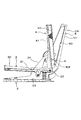
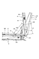
- It is a side sectional view showing an operation of opening and closing the handle unit.
- It is a side sectional view showing an operation of opening and closing the handle unit.
- It is a side sectional view showing an operation of opening and closing the handle unit.
- FIG. 6 is a side sectional view showing an operation of binding a sheet bundle with staples.
- FIG. 6 is a side sectional view showing an operation of binding a sheet bundle with staples.
- It is a side sectional view showing an operation of opening and closing the handle unit.
- It is a side sectional view showing an operation of opening and closing the handle unit.
- FIG. 9 is a side sectional view showing an operation of opening and closing the handle unit to load the staple bundle.
- FIG. 9 is a side sectional view showing an operation of opening and closing the handle unit to load the staple bundle.
- It is a perspective view of the stapler which concerns on 2nd embodiment of this invention. It is a side view of a stapler. It is sectional drawing of a stapler (the 1).
- FIG. 3 is a side view of the stapler with the handle cover and the like removed (No. 1). It is sectional drawing of a stapler (the 2).
- It is a disassembled perspective view of a stapler (the 1).
- It is a disassembled perspective view of a stapler (the 2).
- It is a side view of the stapler which has a holding part.
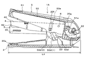
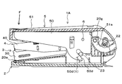
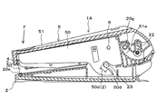
- FIGS. 1 to 17 are side sectional views showing an example of a stapler according to the present embodiment
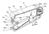
- FIG. 3 is a sectional perspective view showing an example of a stapler
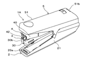
- FIG. 4 is a perspective view showing an example of a stapler
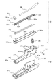
- FIG. 6 is an exploded perspective view showing an example of a stapler
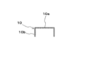
- 7A is a front view showing an example of staples used in a stapler
- FIG. 7B is a perspective view showing an example of staples used in a stapler.
- the staple 10 will be described with reference to FIGS. 7A and 7B.
- the staple 10 includes a crown portion 10a and two leg portions 10b formed by bending both ends of the crown portion 10a so as to be substantially parallel to one direction.
- a plurality of staples 10 are bonded and integrated to form a staple bundle 11 as shown in FIG. 7B.
- the staple 10 is of the standard called JIS No. 10 staple, and has a thickness of about 0.5 mm, and the length L of the staple bundle 11 in which a series of 50 standard staples is connected is about 25 mm.
- the stapler 1A described below uses the JIS No. 10 staple 10 and is a stapler of a size that can be held and operated by hand, and reduces the load required for the operation of binding a sheet bundle.
- the present invention is provided with a booster mechanism, and is further provided with a configuration called a variable booster mechanism in which the reduction rate of the load is switched so that the load is adjusted to the load in each step of the operation of binding the sheet bundle.
- the stapler 1A is a stapler having a variable booster mechanism and of a size that can be held and operated by hand, and a staple unit can be loaded by opening and closing the handle unit.
- the stapler 1A is equipped with a variable booster mechanism, and is a stapler of a size that can be held and operated by hand so that three staple bundles of JIS No. 10 can be loaded.
- the stapler 1A includes a clincher unit 2, a magazine unit 3, a driver unit 4, and a handle unit 5.
- the clincher unit 2 includes a clincher arm 20 and a clincher arm cover 21 that covers the clincher arm 20.
- the clincher arm 20 is formed into a predetermined shape by bending a plate-shaped metal material by die-cutting and bending such as pressing.
- the clincher arm 20 includes a clincher portion 20a that bends the leg portion 10b of the staple 10 on a bottom surface portion 20b on the leading end side that is one end portion side along the extending direction of the clincher arm 20.
- a groove portion that bends the leg portion 10b of the staple 10 into a predetermined shape is formed integrally with the bottom surface portion 20b of the clincher arm 20.
- the clincher arm 20 has a pair of side wall portions 20c in which both side portions on the rear end side, which is the other end portion side along the extending direction of the clincher arm 20, are bent substantially perpendicular to the bottom surface portion 20b. Is formed.
- the clincher arm 20 is provided with a fulcrum pin support portion 20d, which penetrates the pair of side wall portions 20c and into which the fulcrum pin 22 as a fulcrum shaft portion is inserted, on the other end side.
- the fulcrum pin support portion 20d is formed of a hole that penetrates the pair of side wall portions 20c.
- the clincher arm 20 includes a cam shaft support portion 20e, which penetrates the pair of side wall portions 20c and into which the cam shaft 23 that is the cam shaft portion is inserted, between the clincher portion 20a and the fulcrum pin support portion 20d.
- the cam shaft support portion 20e is formed of a hole that penetrates the pair of side wall portions 20c.
- the clincher arm 20 is provided with a regulation convex portion 20f for regulating the opening of the handle unit 5 with respect to the clincher unit 2 between the clincher portion 20a and the camshaft support portion 20e.
- the regulation convex portion 20f is configured by providing a convex portion having a predetermined shape on the outer surface of each of the pair of side wall portions 20c.
- the clincher arm 20 includes a guide protrusion 20g for guiding the opening and closing of the handle unit 5 between the fulcrum pin support 20d and the cam shaft support 20e.
- the guide convex portion 20g is an example of the guide portion, and is configured by providing a cylindrical convex portion on the outer surface of each of the pair of side wall portions 20c.
- the clincher arm cover 21 is made of resin and has a shape that covers the bottom surface portion 20b of the clincher arm 20 and the pair of side wall portions 20c.
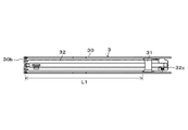
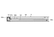
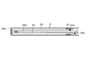
- FIG. 8A is a perspective view showing an example of a magazine unit
- FIG. 8B is a plan view showing an example of a magazine unit
- FIGS. 8C and 8D are sectional views showing an example of a magazine unit.
- the magazine unit 3 includes a magazine 30 in which the staples 10 are loaded, a pusher 31 that presses the staples 10 loaded in the magazine 30 in a line width direction orthogonal to the crown portion 10a, and a pusher guide that guides the movement of the pusher 31. 32, a pusher spring 33 that biases the pusher 31, a pusher band 34 that moves the pusher 31 by opening and closing the handle unit 5, and a magazine return spring 35 that biases the magazine unit 3 in a direction away from the clincher unit 2.
- the magazine 30 is formed into a predetermined shape by bending a plate-shaped metal material by die-cutting and bending work such as pressing, and is provided with a space into which the staple 10 can be loaded and the top surface is opened. That is, in the magazine 30, both side portions of the magazine bottom portion are bent substantially vertically in one direction, so that a pair of magazine side wall portions 30a is formed so as to stand upright from both side portions of the magazine bottom portion. ..
- the magazine 30 is configured such that the inner width of the opposing magazine side wall portions 30a is approximately the same as the outer width of the crown portion 10a of the staple 10 to the extent that the staple bundle 11 can be inserted, and the magazine side wall portions 30a are disposed between the opposing magazine side wall portions 30a.
- the staple 10 can be loaded, and the position of the loaded staple 10 in the width direction is restricted.
- the tip ends of the pair of magazine sidewall portions 30a which are one end portions along the longitudinal direction of the magazine 30, are bent inward to close the tips of the opposing magazine sidewall portions 30a.
- the magazine 30 includes a fulcrum pin support portion 30d, which penetrates the pair of magazine side wall portions 30a and into which the fulcrum pin 22 is inserted, on the rear end side which is one end side along the longitudinal direction of the magazine 30. ..
- the fulcrum pin support portion 30d is a hole portion that penetrates the pair of magazine side wall portions 30a.
- the pusher 31 is made of a resin material such as plastic, and has a pressing portion 31a for pressing the staple 10, a pusher spring locking portion 31b for locking the pusher spring 33, and a band locking (not shown) for locking the pusher band 34. Section.
- the pressing portion 31a is formed in a shape protruding forward from both left and right sides of the tip end side of the pusher 31 facing the magazine front wall portion 30b, and presses the two leg portions 10b of the staple 10.
- the pusher spring locking portion 31b is configured by providing a protrusion on one side surface of the pusher 31 with which one end of the pusher spring 33 can be hooked.
- the pusher guide 32 is made of a resin material such as plastic and extends along the longitudinal direction of the magazine 30.
- the width of the pusher guide 32 in the lateral direction is configured to be narrower than the inner width of the crown portion 10a of the staple 10, and a space where the leg portion 10b of the staple 10 can be inserted is provided between the pusher guide 32 and the magazine side wall portion 30a. It is provided.
- the pusher guide 32 includes a staple guide portion 32a that presses the separated staple 10 against the magazine front wall portion 30b.
- the staple guide portion 32a has a width slightly smaller than the inner width of the crown portion 10a of the staple 10, and is provided integrally with the front end side of the pusher guide 32 so as to face the magazine front wall portion 30b of the magazine 30.
- the pusher guide 32 includes a pusher spring guide portion 32b that guides the pusher spring 33, and a pusher spring locking portion 32c that locks the pusher spring 33.
- the pusher spring guide portion 32b is configured by providing a convex portion on the bottom surface side of the pusher guide 32, which is a tip end side of the pusher guide 32 and which folds back the pusher spring 33 in a U shape.
- the pusher spring locking portion 32c is configured by providing a protrusion on one inner side surface on the rear end side of the pusher guide 32 with which the other end portion of the pusher spring 33 is hooked.
- the pusher guide 32 includes a restriction portion 32d that restricts the magazine unit 3 from opening with respect to the clincher unit 2.
- the restricting portion 32d allows the cam shaft 23 to be inserted into a protrusion protruding from the bottom surface of the magazine in the direction of the clincher unit 2, and the moving direction of the magazine unit 3 relative to the clincher unit 2. It is configured by providing a long hole having a shape extending along.
- the pusher spring 33 is composed of a tension coil spring. One end of the pusher spring 33 is locked to the pusher spring locking portion 31b of the pusher 31. Further, the pusher spring 33 has an intermediate portion folded back in a U shape by the pusher spring guide portion 32b at the tip end side of the pusher guide 32. Furthermore, the other end of the pusher spring 33 is locked to the pusher spring locking portion 32c of the pusher guide 32. As a result, the pusher spring 33 is extended by the movement of the pusher 31 to the rear end side of the magazine 30, and the pusher 31 is pressed toward the front end of the magazine 30 by the force of contraction of the pusher spring 33.
- the pusher band 34 is made of a tape-shaped resin material, and one end of the pusher band 34 is attached to the pusher 31.
- the magazine return spring 35 is composed of a compression coil spring, and is attached between the magazine unit 3 and the clincher unit 2.
- the pusher 31 and the pusher spring 33 are attached to the pusher guide 32 in the above-described form, and the pusher guide 32 to which the pusher 31 and the pusher spring 33 are attached is attached to the inside of the magazine 30.
- the movement of the pusher 31 of the magazine unit 3 is guided by the pusher guide 32. Further, the staple 10 loaded in the magazine 30 is guided by the pusher guide 32 in a state where the pusher 31 is retracted by the operation of loading or unloading the staple bundle 11 in or from the magazine 30, and in particular, the remaining number is small. The collapse of the staple 10 is prevented. Further, the staple 10 which is separated and ejected into one is guided by the staple guide portion 32 a of the pusher guide 32.
- the magazine unit 3 is attached to the clincher unit 2 by inserting the fulcrum pin 22 inserted into the fulcrum pin support portion 20d of the clincher arm 20 into the fulcrum pin support portion 30d of the magazine 30. Further, the cam shaft 23 inserted into the cam shaft support portion 20e of the clincher arm 20 is inserted into the restriction portion 32d of the magazine 30 which protrudes from the bottom surface portion of the magazine.
- the magazine return spring 35 is attached between the bottom surface of the magazine of the magazine 30 and the bottom surface 20b of the clincher arm 20 in a compressed state by a predetermined amount.
- the magazine unit 3 can rotate with respect to the clincher unit 2 with the fulcrum pin 22 as a fulcrum axis, and when the magazine unit 3 rotates in a direction approaching the clincher unit 2, the magazine return spring 35 is compressed. When the compressed magazine return spring 35 is restored, the magazine unit 3 rotates in a direction away from the clincher unit 2, and the rotatable range of the magazine unit 3 is the restriction portion in which the cam shaft 23 is inserted. It is regulated by 32d, and a predetermined space is secured between the magazine 30 and the clincher portion 20a.
- the driver unit 4 includes a driver arm 40, a driver arm return spring 41, a driver 42, and a staple cover 43.
- the driver arm 40 is formed into a predetermined shape by bending a plate-shaped metal material by die-cutting and bending work such as pressing.
- the driver arm 40 has a pair of side wall portions 40b formed by bending both sides of the top surface portion 40a substantially perpendicularly to the top surface portion 40a.
- a driver 42 that separates and ejects the staples 10 loaded in the magazine 30 into one is attached to the top surface portion 40a on the front end side which is one end side along the extending direction of the driver arm 40. ..
- the driver 42 has a width substantially equal to the outer width of the crown portion 10 a of the staple 10 and a plate thickness substantially equal to the line width of the staple 10.
- the fulcrum pin support portion 40c into which the fulcrum pin 22 is inserted through the pair of side wall portions 40b is provided on the rear end side which is the other end portion side along the extension direction of the driver arm 40.
- Prepare The fulcrum pin support portion 40c is a hole portion that penetrates the pair of side wall portions 40b.
- the driver arm 40 is provided with a booster pin support portion 40d into which the booster pin 6 which is the transmission shaft portion is inserted, between the fulcrum pin support portion 40c and the driver 42.
- the boost pin support portion 40d is formed of a hole that penetrates the pair of side wall portions 40b.
- the staple cover 43 is formed into a predetermined shape by bending a plate-shaped metal material by die-cutting and bending work such as pressing.
- the staple cover 43 has a magazine driver locking portion 43a, which is locked with the driver 42 and also with the magazine front wall portion 30b of the magazine 30, on one end side along the extending direction of the staple cover 43. Is provided on the top surface portion 43b on the tip side.
- the staple cover 43 has a pair of side wall portions 43c formed by bending both side portions of the top surface portion 43b substantially perpendicularly to the top surface portion 43b.
- the staple cover 43 is provided with a fulcrum pin support portion 43d supported by the fulcrum pin 22 on the rear end side which is the other end side along the extending direction of the staple cover 43.
- the fulcrum pin support portion 43d is composed of a recess provided in the pair of side wall portions 43c.
- the staple cover 43 is provided with an opening 43e through which the pusher band 34 is inserted between the magazine/driver locking portion 43a and the fulcrum pin support portion 43d.
- the staple cover 43 includes a mounting portion 43f to which the pusher band 34 and the driver arm return spring 41 are locked, between the magazine/driver locking portion 43a and the opening 43e.
- the driver arm return spring 41 is composed of a compression coil spring, and one end of the driver arm return spring 41 is engaged with a mounting portion 43f provided on the upper surface of the top surface portion 40a of the driver arm 40 to form the top surface portion 40a and the top surface portion 43b of the staple cover 43. Mounted between.
- the fulcrum pin 22 inserted into the fulcrum pin support portion 20d of the clincher arm 20 and the fulcrum pin support portion 30d of the magazine 30 is inserted into the fulcrum pin support portion 40c of the driver arm 40, so that the clincher unit is provided. It is attached to 2. Further, the magazine/driver locking portion 43 a of the staple cover 43 is locked to the driver 42, and the fulcrum pin support portion 43 d of the staple cover 43 is supported by the fulcrum pin 22.
- the driver arm return spring 41 is attached between the top surface portion 40a of the driver arm 40 and the top surface portion 43b of the staple cover 43 in a compressed state by a predetermined amount. Further, one end of the pusher band 34 is attached to the pusher 31, and the other end of the pusher band 34 passes through the opening 43e and is attached to the mounting portion 43f.
- the driver unit 4 can rotate with respect to the clincher unit 2 and the magazine unit 3 with the fulcrum pin 22 as a fulcrum axis.
- the pusher band 34 pulls the pusher 31, and the pusher 31 is guided by the pusher guide 32 to move to the rear end side of the magazine 30.
- a space into which the staple 10 can be loaded is formed between the pusher 31 and the inner surface side of the magazine front wall portion 30b.
- the pusher 31 moves to the tip side of the magazine 30 by the pusher spring 33.
- the staple 10 is loaded in the magazine 30, the staple 10 is pressed against the magazine front wall portion 30b by the pusher 31.
- the magazine driver locking portion 43a is locked to the magazine front wall portion 30b of the magazine 30.
- the driver 42 projects into the magazine 30 along the inner surface side of the magazine front wall portion 30b, and the driver arm return spring 41 is compressed.
- the driver 42 By restoring the compressed driver arm return spring 41, the driver 42 is retracted from the magazine 30 by the operation of rotating the driver unit 4 in the direction away from the magazine unit 3. Further, when the compressed driver arm return spring 41 is restored, the range in which the driver unit 4 can rotate is restricted by the driver 42 being locked by the magazine/driver locking portion 43a.
- the handle unit 5 includes a handle arm 50 and a handle arm cover 51.
- the handle arm 50 is formed into a predetermined shape by bending a plate-shaped metal material by die-cutting and bending work such as pressing.
- the handle arm 50 has a pair of side wall portions 50b formed by bending both sides of the top surface portion 50a substantially perpendicularly to the top surface portion 50a.
- the booster pin support portion 50c into which the booster pin 6 is inserted through the pair of side wall portions 50b, is provided on the rear end side which is the other end portion side along the extending direction of the handle arm 50.
- Prepare The boost pin support portion 50c is formed of a hole that penetrates the pair of side wall portions 50b.
- the handle arm 50 includes a cam groove portion 50d, which penetrates the pair of side wall portions 50b and into which the cam shaft 23 is inserted, on the rear end side.
- the cam groove portion 50d is configured by a groove portion that penetrates the pair of side wall portions 50b and has an end portion on the clincher unit 2 side which is one end portion along the direction in which the clincher unit 2 and the handle unit 5 are separated from each other.
- the handle arm 50 includes a restriction recess 50e into which the restriction protrusion 20f of the clincher arm 20 is inserted.
- the restriction recess 50e is a rectangular opening that penetrates through the pair of side wall parts 50b and extends along the moving direction of the handle unit 5 with respect to the clincher unit 2.
- the handle arm cover 51 is made of resin and has a shape that covers the top surface portion 50a of the handle arm 50 and the pair of side wall portions 50b.
- the handle arm cover 51 includes a guide recess 51a into which the guide protrusion 20g of the clincher arm 20 is inserted.
- the guide concave portion 51a is an example of a guide portion, and is formed by providing a groove portion for guiding the handle unit 5 on the inner surface of the handle arm cover 51 by an operation of opening and closing the handle unit 5 with respect to the clincher unit 2.
- the groove portion forming the guide recess may be provided in the handle arm 50.
- the handle arm 50 can be regarded as a rotational motion when the handle arm 50 is moved, depending on the shape of the cam groove portion 50d guided by the cam shaft 23 and the trajectory along which the booster pin 6 can move.
- An imaginary fulcrum shaft when the displacement of the handle arm 50 is regarded as a rotational movement is formed on the rear end side of the handle arm 50.
- the handle arm 50 presses the driver arm 40 via the booster pin 6 by being displaced by a rotating operation with the virtual fulcrum shaft as a fulcrum.
- the contact angle between the cam groove portion 50d and the cam shaft 23 is changed in accordance with the rotating operation of the handle arm 50, so that the direction in which the cam groove portion 50d is guided by the cam shaft 23 is changed, and the handle arm 50 is changed.
- the virtual fulcrum axis of the rotating motion of is moved.
- the cam groove portion 50d a section in which the contact angle with the cam shaft 23 is changed is set according to the portion of the cam groove 23 that changes due to the rotation operation of the handle arm 50.
- the cam groove portion 50d has a predetermined groove shape in which two sections, that is, a first section 50d(1) and a second section 50d(2) are combined.
- the rear end side of the handle arm 50 and the rear end side of the driver arm 40 of the handle arm 50 and the driver arm 40 are rotatably connected by the booster pin 6.
- the booster pin 6 which is a connecting portion between the handle arm 50 and the driver arm 40, is provided in front of the fulcrum pin 22 that supports the rear end side of the driver arm 40 on the clincher arm 20, and the booster pin 6 can move.
- the locus is an arc centered on the fulcrum pin 22.
- the tip end side of the handle unit 5 becomes a force point where a force is applied by the user, and the booster pin 6 that is a connecting portion with the driver arm 40 acts on the driver arm 40.
- the virtual fulcrum axis serves as the fulcrum of the rotational movement.
- the booster pin 6 that is a connecting portion with the handle arm 50 serves as a point of force to which force is applied by the handle arm 50, and the driver 42 serves as a point of action of force on the staple 10 and is a fulcrum.
- the pin 22 serves as a fulcrum of the rotating operation.
- the handle unit 5 connected to the driver unit 4 by the booster pin 6 opens and closes the driver unit 4 toward and away from the clincher unit 2.
- the handle unit 5 and the driver unit 4 realize a booster mechanism in which the load applied to the handle arm 50 is reduced by the force points of the handle arm 50 and the driver arm 40 and the ratio of the distance between the action point and the fulcrum.
- the contact angle between the cam groove portion 50d and the cam shaft 23 is changed in accordance with the rotation operation of the handle arm 50, so that the direction in which the cam groove portion 50d is guided by the cam shaft 23 is changed, and the handle
- a variable booster mechanism that changes the reduction rate of the load applied to the handle arm 50 is realized.
- the handle unit 5 is operated by the operation of holding the sheet bundle between the clincher unit 20a of the clincher unit 2 and the magazine 30 of the magazine unit 3 and the operation of the staple 10 penetrating the sheet bundle to bind the sheet bundle. Change the load applied to.
- the handle unit 5, the driver unit 4, and the magazine unit 3 are moved from the standby state shown in FIG. 1 to the state shown in FIG. 9, and the paper is inserted between the clincher unit 20a of the clincher unit 2 and the magazine 30 of the magazine unit 3.
- the cam shaft 23 is in contact with the first section 50d(1) of the cam groove portion 50d. Note that FIG. 9 does not show the sheet bundle.
- the virtual fulcrum shaft of the handle unit 5 is in the vicinity of the fulcrum pin 22.
- the driver unit 4 moves toward the magazine unit 3
- the driver 42 projects into the magazine 30 along the inner surface side of the magazine front wall portion 30b.
- the leadingmost one staple 10 of the staple bundle 11 loaded in the magazine 30 is separated from the staple bundle 11 and is ejected from the magazine 30.
- the staple 10 ejected from the magazine 30 is bound by the pair of legs 10b penetrating the sheet bundle and being bent inward by the clincher portion 20a.
- the movement amount of the handle arm 50 and the movement amount of the driver arm 40 are close to each other. Therefore, the reduction rate of the load is reduced, but the increase in the operation amount of the handle unit 5 is suppressed. Therefore, in the standby state shown in FIG. 1, the size between the clincher unit 2 and the handle unit 5 can be made smaller than that of a stapler having a booster mechanism but not a variable booster mechanism.
- the movement amount of the handle arm 50 is larger than the movement amount of the driver arm 40, but the reduction rate of the load is increased, and the handle arm is increased. The load on 50 is reduced.
- the load applied to the handle unit 5 is a reaction force of the force pressing the magazine return spring 35. Therefore, even if the reduction rate of the load is low, the load on the worker is not large.
- the leg 10b of the staple 10 penetrates the bundle of sheets, and the leg 10b is further bent, so that the load applied to the handle unit 5 increases. Therefore, in the operation in which the staple 10 penetrates the sheet bundle to bind the sheet bundle, the load applied to the handle arm 50 is reduced by increasing the reduction rate of the load. The load on the operator can be reduced.
- FIG. 12, FIG. 13 and FIG. 14 are side sectional views showing the operation of opening and closing the handle unit, and the operation effect of opening and closing the handle unit 5 in the stapler 1A having the variable booster mechanism will be described.
- the regulation concave portion 50e of the handle unit 5 causes the regulation convex portion 20f of the clincher unit 2 to move. Get out of. Further, the cam groove portion 50d of the handle unit 5 is disengaged from the cam shaft 23. Further, the guide concave portion 51a of the handle unit 5 is guided by the guide convex portion 20g of the clincher unit 2, so that the distal end side of the handle unit 5 moves away from the clincher unit 2 in a state where the movement path of the handle unit 5 is restricted. Move to.
- the driver unit 4 connected to the handle unit 5 by the booster pin 6 is rotated by the fulcrum pin 22 as a fulcrum to move away from the magazine unit 3. Move to.
- the pusher band 34 pulls the pusher 31, and the pusher 31 is guided by the pusher guide 32 to move to the rear end side of the magazine 30, as shown in FIG.
- the driver unit 4 connected to the handle unit 5 by the booster pin 6 supports the fulcrum pin 22 as a fulcrum. With this rotation operation, the clincher unit 2 and the magazine unit 3 move in the rising direction.
- the driver unit 4 connected to the handle unit 5 by the booster pin 6 is rotated by using the fulcrum pin 22 as a fulcrum to perform clincher operation.
- the unit 2 and the magazine unit 3 move toward each other.
- the pusher 31 moves to the tip side of the magazine 30 by the pusher spring 33.
- the staple 10 is loaded in the magazine 30, the staple 10 is pressed against the magazine front wall portion 30b by the pusher 31.
- the guide concave portion 51a of the handle unit 5 is guided by the guide convex portion 20g of the clincher unit 2, whereby the movement path of the handle unit 5 is regulated.
- the handle unit 5 moves in a direction approaching the clincher unit 2 and the magazine unit 3.
- the cam groove portion 50d of the handle unit 5 enters the cam shaft 23.
- the regulation concave portion 50e of the handle unit 5 fits into the regulation convex portion 20f of the clincher unit 2.
- the stapler 1A having the variable booster mechanism moves the contact angle between the cam groove portion 50d and the cam shaft 23 in accordance with the rotation operation of the handle arm 50, thereby moving the virtual fulcrum shaft of the rotation operation of the handle arm 50. It is a configuration that allows it.
- the cam groove portion 50d is configured by a groove portion whose end on the clincher unit 2 side is open. By moving the handle unit 5 in a direction away from the clincher unit 2, the cam groove portion 50d comes out of the cam shaft 23. .. Therefore, the handle unit 5 and the driver unit 4 can be opened with respect to the clincher unit 2 and the magazine unit 3.
- the handle arm 50 is connected to the driver arm 40 of the driver unit 4 by the booster pin 6, and is rotatable with respect to the driver unit 4 with the booster pin 6 as a fulcrum.
- the handle unit 5 and the driver unit 4 move from the state in which the handle unit 5 and the driver unit 4 are opened with respect to the clincher unit 2 and the magazine unit 3 toward the direction in which the handle unit 5 approaches the clincher unit 2. If not determined, it will be difficult to insert the cam groove portion 50d of the handle unit 5 into the cam shaft 23.
- the movement path of the handle unit 5 can be regulated.
- the handle unit 5 moves in a direction in which it approaches the clincher unit 2 and the magazine unit 3.
- the cam groove 50d of the handle unit 5 can enter the cam shaft 23. Therefore, in the stapler 1A provided with the variable booster mechanism, the staple bundle 11 can be loaded by opening and closing the handle unit 5 to open the top side of the magazine 30. Therefore, a mechanism for sliding the magazine is not necessary, and the structure can be simplified and the cost can be reduced.
- FIG. 15 is a side sectional view showing a modified example of the operation of opening and closing the handle unit.
- a regulation convex portion 50f that abuts the driver arm 40 of the driver unit 4 is provided on the inner surface of the handle arm 50 of the handle unit 5.
- the orientation of the handle unit 5 may be restricted.
- 16 and 17 are side cross-sectional views showing the operation of opening and closing the handle unit to load the staple bundle.
- the staple bundle 11 of JIS No. 10 needles is placed in the magazine 30. The function and effect of enabling the loading of three rods will be described.
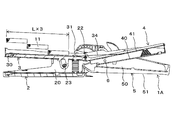
- the length L of the staple bundle 11 in which the staples 10 called JIS No. 10 needles are connected is about 25 mm. For this reason, in order to be able to load the three staple bundles 11 into the magazine 30, as shown in FIG. 17, the pusher 31 is moved to the last retracted position and the inner surface side of the magazine front wall portion 30b is removed. A length of 75 mm or more is required between the pusher 31 and the pusher 31.
- the length L1 of the magazine 30 is set to 90 mm or more and 100 mm or less.
- the length of the magazine 30 is the length from the inner surface side of the magazine front wall portion 30b to the fulcrum pin 22.
- the pusher spring 33 is extended by the movement of the pusher 31 toward the rear end side of the magazine 30 in a state where the pusher 31 is moved to the last retracted position, so that the pusher 31 and the rear end of the magazine 30 are extended.
- a space for accommodating the compressed spring is not required between the side and the side, and the retracted amount of the pusher 31 can be increased. Therefore, it is possible to suppress an increase in the length of the magazine 30 into which the three staple bundles 11 can be loaded.
- the length L2 of the pusher band 34 is set to 51 mm or more and 61 mm or less.
- the length of the pusher band 34 is the length from one end exposed from the pusher 31 to the other end exposed from the opening 43e of the staple cover 43.
- the length L3 from the fulcrum pin 22 to the mounting position of the pusher band 34 with respect to the driver unit 4 is set to 41 mm or more and 50 mm or less.
- the ratio (L1:L2) of the length L1 of the magazine 30 and the length L2 of the pusher band 34 is set to 10:5.7 to 6.1.
- the ratio (L1:L3) between the length L1 of the magazine 30 and the length L3 from the fulcrum pin 22 to the mounting position of the pusher band 34 with respect to the driver unit 4 is set to 10:4.6 to 5.0. ..
- the length L4 of the stapler 1A is set to 105 mm or more and 125 mm or less so that the stapler 1A can be held and operated by hand.
- the length of the stapler 1A is the length from the tip of the clincher arm cover 21 of the clincher unit 2 to the rear end of the handle arm cover 51 of the handle unit 5 in the stapler 1A in the standby state as shown in FIG. ..
- a variable booster mechanism is provided, and at each step of binding a bundle of sheets, The reduction rate of the load can be switched so that the load matches the operation.
- the size between the clincher unit 2 and the handle unit 5 can be made smaller than that of a stapler which is provided with the booster mechanism but does not have the variable booster mechanism.
- the staple bundle 11 can be loaded into the magazine 30 by opening and closing the handle unit 5.
- the stapler 1A is usually used in such a form that a thumb is hooked on the leading end side of the stapler 1A which is the driving side of the staple 10.
- the stapler 1A is gripped with the rear end side up and the driving side of the staple 10 down, and the rear end side of the handle unit 5 is held with the thumb. It is not uncommon to hold the stapler 1A in a so-called reverse-handed manner and use it. Therefore, as shown in FIG. 4, on the rear end side of the handle arm cover 51 of the stapler 1A, when the stapler is used while being held by the other hand, a finger hook portion 51b may be provided at a portion corresponding to the thumb.
- the finger-holding portion 51b is formed by a depression or a protrusion, so that the finger-holding portion 51b has a good feel and is easy to hold, and thus has a good holding property. In addition, it is easy to apply a force during the binding work, the operation feeling is good, and the workability is also improved.
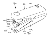
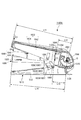
- FIG. 18 is a perspective view of the stapler 1100A according to this embodiment.
- FIG. 19 is a side view of the stapler 1100A.
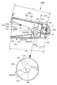
- FIG. 20 is a cross-sectional view when the side surface side of the stapler 1100A is cut.
- 21 is a side view of the stapler 1100A shown in FIG. 20 with the handle cover 1054 and the like removed.
- FIG. 22 is a cross-sectional view when the center side of the stapler 1100A is cut.
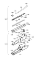
- 23 and 24 are exploded perspective views of the stapler 1100A.
- the stapler 1100A has a fulcrum pin 1062 that receives a load from the handle unit (operation member) 1050 that is displaced by the force of the operator and a fulcrum pin 1062. And a binding member 1070 that rotates relative to the handle unit 1050.
- the binding member 1070 is connected to the magazine unit 1020 in which staples are loaded and is connected to the handle unit 1050 via a boosting pin (coupling portion) 1064, and separates the staple loaded in the magazine unit 1020 into one driver.
- the clincher unit 1010 that rotatably supports the driver unit 1040 having the 1044, the magazine unit 1020, and the driver unit 1040, and that bends the staple that penetrates the paper, and the shaft hole (hole portion) 1122a provided in the clincher unit 1010. It has a cam shaft (shaft portion) 1060 that is supported and supports the handle unit 1050.
- the clincher unit 1010 side is the lower side of the stapler 1100A and the opposite handle unit 1050 side is the upper side of the stapler 1100A.
- the side of the driver 1044 provided in the driver unit 1040 is the front side of the stapler 1100A, and the opposite side is the rear side of the stapler 1100A.
- the clincher unit 1010 includes a clincher arm 1012 that bends the legs of staples that penetrate the bundle of sheets inward and a clincher cover 1014 that protects the clincher arm 1012.
- the clincher arm 1012 is formed by bending a metal plate into a substantially U shape, and has an elongated base portion 1120 extending in the front-rear direction and a rear portion of the base portion 1120. And bearings 1122 and 1124 standing upright from the lateral side surface of the base portion 1120.
- An opening 1120a that can be fitted to a protrusion 1142 formed on a clincher cover 1014 described later is formed behind the center of the base 1120.
- the shaft holes 1122c and 1124c that support the fulcrum pin 1062 are formed at the rear ends of the bearings 1122 and 1124.
- Supports 1122d and 1124d that rotatably support the handle cover 1054 are formed slightly forward of the shaft holes 1122c and 1124c of the bearings 1122 and 1124.
- the support portions 1122d and 1124d are formed to project annularly from the outer surfaces of the bearing portions 1122 and 1124.
- Shaft holes 1122a and 1124a (see FIG. 23) that support the cam shaft 1060 are formed in substantially central portions of the bearing portions 1122 and 1124.
- holding portions 1123a and 1125a for accumulating grease as a lubricant that reduces friction between the cam shaft 1060 and other parts such as the handle unit 1050 are provided. ing. The details of the holding units 1123a and 1125a will be described later.
- the clincher arm 1012 has a clincher groove portion 1126 and a remover 1128.
- the clincher groove portion 1126 is provided at the front end portion of the base portion 1120, and is attached to the attachment portion 1140 of the clincher cover 1014 described later.
- the clincher groove portion 1126 binds a sheet bundle by stapling by bending a pair of staple leg portions penetrating the sheet bundle by a binding force into a spectacle shape.
- the bent shape of the staple is not limited to the spectacle shape, and may be a flat shape. A known technique can be adopted as the mechanism for realizing the flat shape.
- the remover 1128 is provided at the rear end of the base portion 1120, and projects outward from the rear end of the clincher cover 1014.
- the remover 1128 is formed so as to be tapered toward the rear side when viewed from the side, and is inserted between the crown portion of the staple and the sheet bundle to remove the staple from the sheet bundle.
- the clincher cover 1014 is formed by molding, for example, a resin material into a U-shaped cross section, and covers the back surface of the base portion 1120 of the clincher arm 1012 and the side surface portions of the bearing portions 1122 and 1124, respectively. Attached to the clincher arm 1012. A mounting portion 1140 for mounting the clincher arm 1012 is provided on the inner front end portion of the clincher cover 1014. A convex portion 1142 into which the opening 1120a of the clincher arm 1012 is fitted is provided slightly rearward of the center inside the clincher cover 1014.
- the magazine unit 1020 includes a pusher spring 1024, a pusher guide 1026, a pusher 1028, and a pusher band 1030 in addition to the staple 102-loaded magazine 1022.
- the magazine 1022 has an elongated box shape with an open upper portion and a rear portion, and is arranged inside the clincher arm 1012.
- the magazine 1022 can be loaded with a maximum of three consecutive staples formed by adhesively coupling 50 staples.
- an ejection port 1200 for ejecting the leading staple loaded in the magazine 1022 to the sheet bundle side is formed.
- Shaft holes 1222a and 1224a are formed at the rear ends of the side walls 1222 and 1224 that form the magazine 1022, respectively.
- the fulcrum pin 1062 supported by the bearing portions 1122 and 1124 of the clincher arm 1012 is inserted into the shaft holes 1222a and 1224a. This allows the magazine 1022 to rotate relative to the clincher arm 1012 with the fulcrum pin 1062 of the clincher arm 1012 as a fulcrum.
- a magazine return spring 1034 made of a compression spring is arranged between the rear part of the clincher arm 1012 and the rear part of the magazine 1022.
- the magazine return spring 1034 rotationally biases the magazine 1022 toward the driver unit 1040, and secures a gap for inserting a sheet bundle between the clincher groove portion 1126 and the ejection port 1200 of the magazine 1022.
- the pusher guide 1026 is made of a plate-shaped member extending in the front-rear direction, and is arranged in the magazine 1022.
- the lower surface of the pusher guide 1026 on the rear side is provided with a restriction portion 1260 that projects (exposes) toward the clincher arm 1012 side from an opening (not shown) formed in the lower surface of the magazine 1022.
- a long hole 1260a extending in the vertical direction is formed in the restriction portion 1260.
- the cam shaft 1060 supported by the clincher arm 1012 is inserted into the long hole 1260a of the restriction portion 1260, and the vertical movement range of the magazine 1022 is restricted by the long hole 1260a.
- the pusher 1028 is a member that presses the staples loaded in the magazine 1022 toward the ejection port 1200 side, and is slidably engaged with the pusher guide 1026.
- the pusher spring 1024 is a U-shaped tension spring and is arranged between the magazine 1022 and the pusher guide 1026.
- the open side of the pusher spring 1024 faces rearward.
- One end of the pusher spring 1024 is attached to a mounting portion 1262 provided at the rear end of the pusher guide 1026, and the other end of the pusher spring 1024 is attached to a mounting portion (not shown) provided on the pusher 1028.
- the pusher 1028 is urged toward the ejection port 1200 by the pusher spring 1024 to urge the staples loaded in the magazine 1022 toward the ejection port 1200 and move the staples to the ejection port 1200 side. To move.
- the staple cover 1032 has a length that is substantially the same as the length of the magazine 1022 in the front-rear direction, and covers the staple loaded in the magazine 1022.
- a mounting portion 1320 is provided on the front end side of the upper surface of the staple cover 1032.
- the other end of the pusher band 1030 and one end of a driver arm return spring 1046 formed of a compression spring are engaged with the mounting portion 1320.
- Engaging portions 1322 and 1324 that rotatably engage with the fulcrum pin 1062 supported by the clincher arm 1012 are provided at the rear end portion of the staple cover 1032.
- An opening 1326 for attaching the pusher band 1030 to the mounting portion 1320 on the upper surface of the staple cover 1032 is provided slightly forward of the engaging portion 1322 and the like of the staple cover 1032.
- the pusher band 1030 is made of, for example, a long film member.
- One end 1300 of the pusher band 1030 is attached to the pusher 1028, the pusher band 1030 passes through the opening 1326, and the other end 1302 of the pusher band 1030 is attached to the attachment portion 1320 provided on the staple cover 1032. ..
- a driver arm return spring 1046 formed of a compression spring is arranged between the staple cover 1032 and the driver arm 1042 as shown in FIGS. 22 and 24.
- the driver arm return spring 1046 rotationally biases the driver arm 1042 so that the driver 1044 waits at a predetermined position above the ejection port 1200 of the magazine 1022.
- the driver unit 1040 receives a force from the handle unit 1050 by the booster pin 1064 and is displaced by a rotation operation, and a driver arm 1042 rotates to press the leading staple loaded in the magazine 1022 to press a bundle of sheets. And a driver 1044 for penetrating.
- the driver arm 1042 is arranged between the inner surface of the clincher arm 1012 and the outer surface of the magazine 1022, and is rotatably attached to the bearing portions 1122 and 1124 of the clincher arm 1012.
- the driver arm 1042 is formed by bending a metal plate into a substantially U shape, and has a long top surface portion 1420 extending in the front-rear direction and a lateral surface of the top surface portion 1420. It has side surface portions 1422 and 1424 extending downward.
- a mounting portion 1420a for mounting the driver 1044 is provided on the lower surface on the front end side of the top surface portion 1420.
- Shaft holes 1422a and 1424a are formed in the rear end portions of the side surface portions 1422 and 1424, respectively.
- the fulcrum pin 1062 supported by the bearings 1122 and 1124 of the clincher arm 1012 is inserted into the shaft holes 1422a and 1424a.
- the driver arm 1042 can rotate relative to the clincher arm 1012 with the fulcrum pin 1062 of the clincher arm 1012 as a fulcrum.
- the driver 1044 is formed by bending a metal plate into a substantially inverted L shape, and has a mounting portion 1440 and a pressing portion 1442.
- An opening 1440a is formed in the mounting portion 1440, and the opening 1440a is fitted to the mounting portion 1420a of the driver arm 1042.
- the width of the pressing portion 1442 in the left-right direction is selected to be substantially the same as the dimension of the crown portion of the staple, and the plate thickness of the pressing portion 1442 is selected to be substantially the same as the needle line width of one staple.
- the handle unit 1050 includes a handle arm 1052 that presses the driver arm 1042 and a handle cover 1054 that protects the handle arm 1052.
- the handle arm 1052 is formed by bending a metal plate into a substantially U shape, and has a long top surface portion 1520 extending in the front-rear direction and a top surface portion 1520. Has side surface portions 1522 and 1524 extending downward from the side surface in the left-right direction.
- a booster pin 1064 is inserted in the rear portion of the side surfaces 1522, 1524 of the handle arm 1052, and the handle arm 1052 is rotatably supported by the driver arm 1042 via the booster pin 1064.
- the boost pin 1064 is provided in front of the fulcrum pin 1062.
- a cam groove (guide portion) 1056 that is slidable on the cam shaft 1060 of the clincher arm 1012 is formed in a portion projecting downward from the rear portion of the side surface portion 1522.
- the cam groove 1056 is configured such that the lower end side is open. Accordingly, when the handle unit 1050 is opened, the cam groove 1056 of the handle arm 1052 is disengaged from the cam shaft 1060, so that the upper side of the magazine 1022 is opened and staples can be loaded from the upper side of the magazine 1022. ..
- the side surface portion 1524 has the same function and shape as the above-described cam groove 1056.
- a cam groove is provided as a guide portion.
- the handle cover 1054 is formed by bending a resin plate into a substantially inverted U shape, and is formed on the outer peripheral surface of the handle arm 1052, the rear portion of the driver unit 1040, and the magazine unit 1020. Cover each of the rear.
- the fulcrum pin 1062 supported by the bearings 1122 and 1124 of the clincher arm 1012 is located in the groove portion 1544 provided inside the rear portion of the handle cover 1054, and the fulcrum pin 1062 moves up and down when the handle cover 1054 is opened and closed. It functions as a moving escape groove.
- a groove-shaped guide portion 1540 that slidably engages with the support portion 1122d of the clincher arm 1012 is formed inside the rear side surface of the handle cover 1054.
- FIG. 20 shows only the guide portion 1540 on the left side surface, a similar guide portion is also provided on the right side surface.
- the guide portion 1540 regulates the rotation trajectory of the handle unit 1050 when the handle unit 1050 is opened with respect to the clincher unit 1010 and the like.
- the guide portion 1540 guides the open side of the cam groove 1056 of the handle unit 1050, which is disengaged from the cam shaft 1060, to the cam shaft 1060 when the handle unit 1050 is closed with respect to the clincher unit 1010 and the like.
- variable booster mechanism in the stapler 1100A according to the present embodiment will be described with reference to FIGS. Note that, in the following, since the side surface portions 1522 and 1524 of the handle arm 1052 are symmetrical and have a common configuration, only one side surface portion 1522 side will be described in order to simplify the description.
- the handle arm 1052 is made minute by the trajectory of the booster pin 1064 that can move when a force is applied to the front end side of the handle unit 1050 and the shape of the cam groove 1056 guided by the cam shaft 1060.
- the movement when moved to can be regarded as a rotation movement.
- a fulcrum axis O that is a virtual rotation fulcrum when the displacement of the handle arm 1052 is regarded as a rotational movement is formed on the rear end side of the handle arm 1052.
- the handle arm 1052 is displaced by a rotational movement about a fulcrum axis O (shown by a cross in FIG. 20) as a fulcrum to press the driver arm 1042 via the booster pin 1064.
- the contact angle between the cam groove 1056 and the cam shaft 1060 is changed in accordance with the rotating operation of the handle arm 1052 based on the pressing operation of the handle unit 1050, so that the cam groove 1056 and the cam shaft 1060 are separated from each other.
- the contact direction By changing the contact direction, the fulcrum axis O of the rotational movement of the handle arm 1052 is moved.
- the cam groove 1056 has a predetermined elongated hole shape in which three sections, a first section 1056 (1001), a second section 1056 (1002) and a third section 1056 (1003) are combined. Composed of.
- the first section 1056 (1001) of the cam groove 1056 is a section that comes into contact with the cam shaft 1060 when the stapler 1100A is in the standby state, is located at the lower end of the cam groove 1056, and has a contact angle with the cam shaft 1060. It is inclined in a direction substantially orthogonal to the horizontal direction.
- the second section 1056 (1002) of the cam groove 1056 is a section that comes into contact with the cam shaft 1060 when the stapler 1100A switches from the standby state to the boosting state, and continues to the upper side of the first section 1056 (1001).
- the contact angle with the cam shaft 1060 is slightly horizontal with respect to the first section 1056 (1001).
- the third section 1056 (1003) of the cam groove 1056 is a section that comes into contact with the cam shaft 1060 when the clinching operation of the stapler 1100A is completed in the boosted state, and is on the upper side of the second section 1056 (1002).
- the contact angle with the cam shaft 1060 is inclined in the horizontal direction from the second section 1056 (1002).
- the booster pin 1064 is provided in front of the fulcrum pin 1062 supporting the driver arm 1042.
- the locus along which the booster pin 1064 can move is an arc centered on the fulcrum pin 1062.
- the front end side of the handle unit 1050 becomes the force point E1 to which force is applied by the operator, and the booster pin which is the connecting portion between the driver arm 42 and the handle arm 1052.
- 1064 becomes the point of action E2 of the force on the driver arm 1042, and the fulcrum axis O becomes the fulcrum of the rotational operation.
- the booster pin 1064 which is the connecting portion between the driver arm 1042 and the handle arm 1052, becomes the force point E3 at which the force is applied by the handle arm 1052, and the driver 1044 becomes the point of action E4 of the force on the staple.
- the fulcrum pin 1062 serves as the fulcrum of the rotation operation.
- the handle unit 1050 and the driver unit 1040 realize a variable boosting mechanism in which the load F applied to the handle arm 1052 is reduced by the ratio of the force point and the distance between the working point and the fulcrum in the handle arm 1052 and the driver arm 1042.
- the reduction rate D (%) of the load F applied to the handle arm 1052 is calculated by the following equation (1).
- the length from the force point E1 where the force is applied to the handle arm 1052 to the fulcrum axis O which is the rotation fulcrum of the handle arm 1052 is L11, and the force is applied to the driver arm 1042.
- L12 be the length from the booster pin 1064, which is the point of action E2 for multiplying by, to the fulcrum axis O.
- the length from the booster pin 1064, which is the force point E3 where the force is applied to the driver arm 1042, to the fulcrum pin 1062, which is the rotation fulcrum of the driver arm 1042, is L13, and the driver 44 which is the action point E4.
- the length from to the fulcrum pin 1062 is L14.
- the cam groove 1056 is formed in the shape of an elongated hole having three sections, so that the fulcrum shaft of the handle arm 1052 corresponds to the position of the handle arm 1052 in the operation of binding the sheet bundle. O is moved from the vicinity of the fulcrum pin 1062 toward the booster pin 1064.
- the first section 1056 (1001) in which the bundle of sheets is sandwiched between the clincher arm 1012 and the magazine unit 1020 the movement amount of the handle arm 1052 and the movement amount of the driver arm 1042 are close to each other. Therefore, the reduction rate of the load is reduced, but the increase in the operation amount of the handle arm 1052 is suppressed.
- the movement amount of the handle arm 1052 increases but the load is increased.
- the reduction rate is increased, and the load applied to the handle arm 1052 is reduced.
- the load F applied to the handle arm 1052 is gradually reduced so that the load F is adjusted to the operation, and the load is applied when the staple penetrates the sheet bundle. Make F lighter.
- the cam groove 1056 and the cam shaft 1060 are provided around the shaft hole 1122a by providing the holding portion 1123a for storing the grease that reduces the friction between the cam groove 1056 and the cam shaft 1060. It is intended to suppress the occurrence of sliding failure between and.
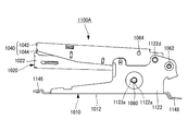
- FIG. 25A is a side view of the stapler 1100A
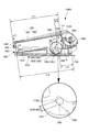
- FIG. 25B is an enlarged view of a main part of the holding unit 1123a
- FIG. 26 is a perspective view of the bearing 1122 including the holder 1123a.
- the diameter D1 of the shaft hole 1122a and the diameter D2 of the cam shaft 1060 are substantially the same.
- the bearing portion 1124 facing the bearing portion 1122 is also provided with the holding portion 1125a. Since the holding portion 1125a on the bearing portion 1124 side has the same function and configuration as the holding portion 1123a on the bearing portion 1122 side, detailed description will be omitted.
- the holding portion 1123a is a part of the periphery of the shaft hole 1122a, and is provided on the opposite side to the direction H1 in which the cam shaft 1060 is abutted against the shaft hole 1122a by the cam groove 1056 due to the load when the handle arm 1052 slides. ing. As a result, the area of the shaft hole 1122a on the side where the cam shaft 1060 is abutted can be secured, so that grease can be provided in the vicinity of the shaft hole 1122a without affecting the surface pressure between the cam shaft 1060 and the shaft hole 1122a. Can be stored.
- the holding portion 1123a is formed in a recessed shape which is cut out in a substantially semicircular shape when seen in a plan view from the peripheral portion of the shaft hole 1122a toward the clincher groove portion 1126 (front side) in the radial direction.
- the size of the holding portion 1123a can be arbitrarily designed according to the amount of grease held.
- the shape of the holding portion 1123a is not limited to the semicircular shape in plan view, and may be, for example, a rectangular shape. Further, either one of the holding portions 1123a and 1125a may be provided, or two holding portions may be provided. Further, although the holding portion 1123a has a shape in which at least a part of the outer surface of the bearing portion 1122 is recessed, the holding portion 1123a may be formed so as to penetrate the bearing portion 1122 in the thickness direction (horizontal direction).
- [Operation example of stapler 1100A] 27 to 29 are diagrams showing an example of the operation of the stapler 1100A according to the present embodiment.
- the holding portion 1123a is preliminarily coated with grease and a certain amount of grease is accumulated in the holding portion 1123a, and then the assembling is completed. 1100A is sold to the operator.
- the application timing of grease is not limited to the manufacturing time, and may be after the stapler 1100A is sold.
- the cam groove 1056 of the handle arm 1052 is in contact with the cam shaft 1060 in the first section 1056 (1001).
- the cam groove 1056 of the handle arm 1052 is in contact with the cam shaft 1060 in the first section 1056 (1001)
- the movement when the handle arm 1052 is slightly moved can be regarded as a rotational movement. Therefore, a fulcrum axis O that is a virtual rotation fulcrum of the handle arm 1052 is formed near the fulcrum pin 1062 that is a rotation fulcrum of the driver arm 1042.
- the cam groove 1056 is guided by the cam shaft 1060, so that the handle arm 1052 and the handle cover 1054 move the fulcrum shaft O formed near the fulcrum pin 1062. It is displaced by the rotation operation using the fulcrum, and the contact portion of the cam groove 1056 with respect to the cam shaft 1060 moves.
- a sheet bundle (not shown) composed of a predetermined number of sheets is sandwiched between the clincher unit 1010 and the magazine 1022. Further, as shown in FIG. 28, the cam groove 1056 of the handle arm 1052 comes into contact with the cam shaft 1060 in the second section 1056 (1002). The grease constantly exudes from the holding portion 1123a, and the exuded grease is supplied to each of the edge portion of the shaft hole 1122a and the peripheral surface of the cam shaft 1060.
- the rotation of the handle arm 1052 changes the contact angle with the cam shaft 1060 to be smaller than that in the first section 1056 (1001).
- the fulcrum shaft O of the handle arm 1052 moves from the vicinity of the fulcrum pin 1062 toward the booster pin 1064.
- the driver arm 1042 When the handle cover 1054 is further pressed from the state where the sheet bundle is nipped, the driver arm 1042 is pressed by the displacement of the booster pin 1064 due to the rotation operation of the handle arm 1052. At this time, the driver arm 1042 rotates about the fulcrum pin 1062 as a fulcrum while the rotation of the magazine 1022 is restricted. By the rotation of the driver arm 1042, the connected staples are pressed by the driver 1044 to be separated into one staple, and the separated staple is ejected from the ejection port 1200 and penetrates the sheet bundle P (not shown).
- the cam groove 1056 of the handle arm 1052 causes the third groove 1056 (1003) to move as shown in FIG. Then, the cam shaft 1060 comes into contact.
- the contact portion between the cam groove 1056 and the cam shaft 1060 moves from the second section 1056 (1002) to the third section 1056 (1003)
- the fulcrum shaft O moves between the fulcrum pin 1062 and the boost pin 1064. The point moves to the booster pin 1064 side.
- the grease exudes from the holding portion 1123a, and the exuded grease is supplied to each of the edge portion of the shaft hole 1122a and the peripheral surface of the cam shaft 1060.
- the driver arm 1042 is pressed by the displacement of the booster pin 1064 due to the rotation operation of the handle arm 1052, and the rotation of the magazine 1022 is restricted. 1042 further rotates around the fulcrum pin 1062 as a fulcrum.
- the tip ends of the leg portions of the staple project from the back surface of the sheet bundle, the leg portions are bent inward by the clincher groove portion 1126, and the sheet bundle is bound by the staple.
- the third section 1056 (1003) of the cam groove 1056 is formed on the booster pin 1064 side from the midpoint between the fulcrum pin 1062 and the booster pin 1064 by being guided by the cam shaft 1060. It rotates about the fulcrum axis O.
- the third section 1056 (1003) of the cam groove 1056 has the center of the arc aligned with the fulcrum axis O. O does not move.
- the holding portion 1123a for accumulating grease is provided around the shaft hole 1122a, grease can be supplied to the shaft hole 1122a and the cam shaft 1060. Therefore, even when the number of stitches is increased, the grease is constantly supplied from the holding portion 1123a to the cam shaft 1060 and the like, so that the sliding failure between the cam groove 1056 of the handle arm 1052 and the cam shaft 1060 can be prevented. Therefore, the sliding of the cam groove 1056 can be maintained smoothly. As a result, the number of times of endurance can be increased even in the stapler 1100A including the variable booster mechanism that places a high load on the cam shaft 1060 and the like.
- a holding portion 1123b which is a first modified example of the above-mentioned holding portion 1123a for storing grease, will be described. Since the stapler 1100B according to the first modification has the same configuration and function as the stapler 1100A of the above-described embodiment, the same reference numerals are used for common configurations, and detailed description is omitted or simplified. To do.
- FIG. 30A is a perspective view of a bearing 1122 having a holding portion 1123b according to the first modification
- FIG. 30B is an enlarged view of a main part of the holding portion 1123b according to the first modification.
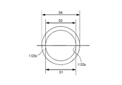
- the holding portion 1123b is formed by notching the outer peripheral portion of the shaft hole 1122a of the bearing portion 1122 facing the cam groove 1056 of the handle arm 1052 in a stepped shape over the entire circumference.
- the inner diameter D3 of the holding portion 1123b is selected to be substantially the same as the diameter D1 of the shaft hole 1122a, and the outer diameter D4 of the holding portion 1123b is selected to be slightly larger than the diameter D1 of the shaft hole 1122a.
- the holding portion 1123b is configured by the annular groove (recess) that does not penetrate the bearing portion 1122 in the thickness direction and is planarly viewed.
- the depth of the holding portion 1123b in the thickness direction and the outer diameter D4 of the holding portion 1123b can be arbitrarily configured according to the amount of grease stored.
- the holding portion 1123b has an outer shape of a perfect circle, but may have an elliptical shape or a rectangular shape. Further, the example in which the holding portion 1123b is provided over the entire circumference of the shaft hole 1122a has been described, but the holding portion 1123b may be provided in a part of the shaft hole 1122a in the circumferential direction.
- the holding portion 1123b for accumulating grease is provided, so that the grease can be constantly supplied to the shaft hole 1122a and the cam shaft 1060.
- sliding failure between the cam groove 1056 of the handle arm 1052 and the cam shaft 1060 can be prevented, and sliding of the handle arm 1052 having the cam groove 1056 can be maintained smoothly.
- the number of times of endurance can be increased even in the stapler 1100B including the variable booster mechanism that places a high load on the camshaft 1060 and the like.
- a holding portion 1123c which is a second modification of the holding portion 1123a that stores the grease described above. Since the stapler 1100C according to the second modification has the same configuration and function as the stapler 1100A of the above-described embodiment, the same reference numerals are used for common configurations, and detailed description is omitted or simplified. To do.
- FIG. 31A is a side view of a stapler 1100C having a holding portion 1123c according to the second modification
- FIG. 31B is an enlarged view of a main portion of the holding portion 1123c.
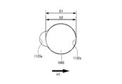
- the holding portion 1123c is provided in a part of the periphery of the shaft hole 1122a, and the side of the shaft hole 1122a opposite to the direction H1 in which the cam groove 1056 is abutted extends toward the clincher groove portion 1126 (forward) side in the radial direction. Formed by that. More specifically, the holding portion 1123c is configured by a hole portion including an elliptical shaft hole 1122a having a long side D5 and a short side D6, excluding the shaft hole 1122a (cam shaft 1060).
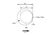
- a holding portion 1123d which is a third modified example of the holding portion 1123a that stores grease described above, will be described. Since the stapler 1100D according to the third modification has the same configuration and function as the stapler 1100A of the above-described embodiment, the same reference numerals are used for common configurations, and detailed description is omitted or simplified. To do.
- FIG. 32A is a perspective view of a stapler 1100D having a holding portion 1123d according to the third modification
- FIG. 32B is a plan view of the holding portion 1123d according to the third modification.
- the holding portion 1123d is provided in a part of the periphery of the shaft hole 1122a, and the side of the shaft hole 1122a opposite to the direction H1 in which the cam groove 1056 is abutted is expanded toward the radial clincher groove 1126 (front) side. It is composed of holes. More specifically, the diameter D7 of the holding portion 1123d is made larger than the diameter D1 of the shaft hole 1122a, and the edge portion 1123de of the holding portion 1123d in the direction H1 and the edge portion 1122ae of the shaft hole 1122a in the direction H1 are overlapped. When configured, the holding portion 1123d is configured by a hole portion other than the shaft hole 1122a.
- the holding portion 1123d for accumulating grease since the holding portion 1123d for accumulating grease is provided, the grease can be constantly supplied to the shaft hole 1122a and the cam shaft 1060. As a result, sliding failure between the cam groove 1056 of the handle arm 1052 and the cam shaft 1060 can be prevented, and the sliding of the cam groove 1056 can be maintained smoothly. As a result, the number of times of endurance can be increased even in the stapler 1100D including the variable booster mechanism that places a high load on the cam shaft 1060 and the like.
- the technical scope of the present invention is not limited to the above-described embodiments, and includes various modifications of the above-described embodiments without departing from the spirit of the present invention.
- the holding portion 1123a is provided around the shaft hole 1122a of the bearing portion 1122 in order to prevent sliding failure between the cam groove 1056 of the handle arm 1052 and the cam shaft 1060
- the present invention is not limited to this. There is no such thing.
- the cam groove 1056 is provided in the first section 1056 (1001), the second section 1056 (1002), and the third section 1056 (1003) as means for realizing the variable boosting mechanism.
- the cam groove 1056 may be composed of two sections, a first section 1056 (1001) and a second section 1056 (1002).
- the third section 1056 (1003) is configured as the second section 1056 (1002).
- a stapler having a guide portion that regulates a movement path of the handle unit with respect to the clincher unit by an operation of opening and closing the handle unit and the driver unit with respect to the clincher unit and the magazine unit.
- the guide portion includes a guide convex portion provided on one of the clincher unit and the handle unit, and a guide concave portion provided on the other of the clincher unit and the handle unit and into which the guide convex portion is inserted.
- a clincher unit having a clincher portion for bending the leg portion of the staple on one end side
- a magazine unit having a staple bundle in which staples are connected is loaded, on the other end side of the clincher unit, with a fulcrum shaft portion as a fulcrum, a magazine unit rotatably supported with respect to the clincher unit
- a driver unit that has a driver for ejecting staples from the magazine on one end side, and the other end side is rotatably supported with respect to the clincher unit with the fulcrum shaft portion as a fulcrum
- a handle shaft unit which is connected to the driver unit by a transmission shaft portion provided between the fulcrum shaft portion and the driver, and which opens and closes the driver unit in a direction approaching the clincher unit;
- the magazine unit a pusher provided so as to be movable along the longitudinal direction of the magazine, A pusher spring for pressing the pusher in the direction of the magazine front wall portion of the magazine, One end is attached to the
- a cam shaft portion provided on either one of the clincher unit and the handle unit, The cam shaft portion is provided in either the clincher unit or the handle unit, and the cam shaft portion is inserted, and one end portion along the direction in which the clincher unit and the handle unit are separated is opened, and the cam shaft portion is inserted and removed.
- the stapler according to (4) which is provided with a cam groove portion to be formed.
- the ratio of the length of the magazine 30 to the length of the pusher band is 10:5.7 to 6.1
- the stapler according to (4) or (5), wherein the ratio of the length of the magazine 30 and the length from the fulcrum shaft portion to the position where the pusher band is attached to the driver unit is 10:4.6 to 5.0.
- An operation member that is displaced by receiving the force of the operator A clincher unit having a clincher groove for bending the staple leg portion at the front end, A shaft portion supporting the operating member, which is supported by a hole portion provided in the clincher unit, The hole portion has a holding portion for storing a lubricant that reduces friction between the shaft portion and the operating member, Stapler.
- the holding portion is provided in at least a part of the periphery of the hole portion, (7) stapler.
- the holding portion is provided in a concave shape in the radial direction of the hole, (8) stapler.
- the holding portion is provided in a direction opposite to the direction in which the shaft portion is abutted by the load of the operation member, The stapler of (8) or (9).
- a driver which is connected to the operation member via a connecting portion and separates and ejects the staple loaded in the loading portion into one, the force of the operating member is received by the connecting portion and is rotated.
- Displaceable driver unit A magazine unit in which staples are loaded,
- the clincher unit rotatably supports the driver unit and the magazine unit at the rear end
- the operation member is A guide portion slidably engaged with the shaft portion,
- the force receiving portion and the length up to the fulcrum axis of the rotational movement, and the portion acting on the force and the length up to the fulcrum axis are changed by moving the fulcrum axis according to the operation of the operation member, Change the reduction rate of the load on the operating member,
- the stapler according to any one of (7) to (10).
- the holding portion is provided in a stepped shape on the surface around the hole, (8) stapler.
- the holding portion is provided by radially expanding a circumferential portion of the hole portion, (8) stapler.
Landscapes
- Engineering & Computer Science (AREA)
- Mechanical Engineering (AREA)
- Portable Nailing Machines And Staplers (AREA)
Abstract
Description
<ステープラの構成例>
図1、図2は、本実施の形態に係るステープラの一例を示す側断面図、図3は、ステープラの一例を示す断面斜視図、図4は、ステープラの一例を示す斜視図、図5及び図6は、ステープラの一例を示す分解斜視図である。また、図7Aは、ステープラで使用されるステープルの一例を示す正面図、図7Bは、ステープラで使用されるステープルの一例を示す斜視図である。
図9、図10は、ステープルで用紙束を綴じる動作を示す側断面図であり、可変倍力機構の作用効果について説明する。
ステープラ1100Aは、図18、図19及び図21等に示すように、操作者の力を受けて変位するハンドルユニット(操作部材)1050と、ハンドルユニット1050からの荷重を受けて支点ピン1062を支点としてハンドルユニット1050に対して相対的に回動する綴じ部材1070とを備えている。綴じ部材1070は、ステープルが装填されるマガジンユニット1020と、ハンドルユニット1050に倍力ピン(連結部)1064を介して連結され、マガジンユニット1020に装填されるステープルを1本に分離して打ち出すドライバ1044を有するドライバユニット1040と、マガジンユニット1020及びドライバユニット1040を回転可能に支持するとともに、用紙を貫通したステープルを折り曲げるクリンチャユニット1010と、クリンチャユニット1010に設けられた軸孔(孔部)1122aに支持され、ハンドルユニット1050を支持するカム軸(軸部)1060を有している。
クリンチャユニット1010は、用紙束を貫通したステープルの脚部を内側に折り曲げるクリンチャアーム1012と、クリンチャアーム1012を保護するクリンチャカバー1014とを備えている。
マガジンユニット1020は、ステープルを装填するマガジン1022に加えて、プッシャバネ1024、プッシャガイド1026、プッシャ1028及びプッシャバンド1030を備えている。
ドライバユニット1040は、ハンドルユニット1050からの力を倍力ピン1064で受けて回転動作で変位するドライバアーム1042と、ドライバアーム1042の回転によりマガジン1022に装填された先頭のステープルを押圧して用紙束を貫通させるドライバ1044とを備えている。
ハンドルユニット1050は、ドライバアーム1042を押圧するハンドルアーム1052と、ハンドルアーム1052を保護するハンドルカバー1054とを備えている。
次に、本実施の形態に係るステープラ1100Aにおける可変倍力機構について図20及び図21等を参照して説明する。なお、以下では、ハンドルアーム1052の側面部1522,1524は、左右対称で共通の構成であるため、説明の簡易化を図るため、一方の側面部1522側についてのみ説明する。

ところで、上述したようなステープラ1100Aにおいて可変倍力機構を採用した場合、綴じ処理を行う毎に、ハンドルアーム1052のカム溝1056がカム軸1060に接触しながらスライドするため、カム溝1056とカム軸1060との間の面圧が高くなり、軸受け部1122に大きな負荷がかかる。ここで、従来のステープラでは、カム軸1060の径と軸孔1122aの径とは略同一に選定されることから、カム軸1060との軸孔1122aとの隙間に塗布可能なグリス量は一定に制限されてしまう場合がある。そのため、ステープラ1100Aの繰り返しの使用によりグリス量が減少していくと、カム溝1056で摺動不良が発生してしまうという問題があった。
図27~図29は、本実施の形態に係るステープラ1100Aの動作の一例を示す図である。なお、本実施の形態では、例えばステープラ1100Aの製造段階の組み付け時において、保持部1123aに予めグリスが塗布され、保持部1123aに一定量のグリスが溜まった状態とし、その後、組み付けが完成したステープラ1100Aが操作者に販売される。なお、グリスの塗布タイミングは製造時に限定されることはなく、ステープラ1100Aの販売後であっても良い。
次に、上述したグリスを溜める保持部1123aの第1変形例である保持部1123bについて説明する。なお、第1変形例に係るステープラ1100Bは、上述した実施の形態のステープラ1100Aと同様の構成及び機能を有するため、共通する構成については同一の符号を用い、詳細な説明については省略又は簡略化する。
次に、上述したグリスを溜める保持部1123aの第2変形例である保持部1123cについて説明する。なお、第2変形例に係るステープラ1100Cは、上述した実施の形態のステープラ1100Aと同様の構成及び機能を有するため、共通する構成については同一の符号を用い、詳細な説明については省略又は簡略化する。
次に、上述したグリスを溜める保持部1123aの第3変形例である保持部1123dについて説明する。なお、第3変形例に係るステープラ1100Dは、上述した実施の形態のステープラ1100Aと同様の構成及び機能を有するため、共通する構成については同一の符号を用い、詳細な説明については省略又は簡略化する。
(1)
ステープルの脚部を曲げるクリンチャ部を一方の端部側に有したクリンチャユニットと、
ステープルが連結されたステープル束が装填されるマガジンを有し、前記クリンチャユニットの他方の端部側に、支点軸部を支点に、前記クリンチャユニットに対して回転可能に支持されるマガジンユニットと、
前記マガジンからステープルを打ち出すドライバを一方の端部側に有し、他方の端部側が、前記支点軸部を支点に、前記クリンチャユニットに対して回転可能に支持されるドライバユニットと、
前記支点軸部と前記ドライバとの間に設けられる伝達軸部で前記ドライバユニットと連結され、前記ドライバユニットを前記クリンチャユニットに近づく方向に開閉移動させるハンドルユニットと、
前記クリンチャユニットと前記ハンドルユニットのどちらか一方に設けられるカム軸部と、
前記クリンチャユニットと前記ハンドルユニットのどちらか他方に設けられ、前記カム軸部が入ると共に、前記クリンチャユニットと前記ハンドルユニットが離れる方向に沿った一方の端部が開口して前記カム軸部が挿抜されるカム溝部と、
前記クリンチャユニット及び前記マガジンユニットに対して前記ハンドルユニット及び前記ドライバユニットを開閉する動作で、前記クリンチャユニットに対する前記ハンドルユニットの移動経路を規制するガイド部と
を備えたステープラ。
(2)
前記クリンチャユニット及び前記マガジンユニットに対して前記ハンドルユニット及び前記ドライバユニットを開く動作で、前記カム溝部から前記カム軸部が抜け、
前記クリンチャユニット及び前記マガジンユニットに対して前記ハンドルユニット及び前記ドライバユニットを閉じる動作で、前記クリンチャユニットに対する前記ハンドルユニットの移動経路が前記ガイド部で規制されて、前記カム軸部が前記カム溝部に入る
(1)のステープラ。
(3)
前記ガイド部は、前記クリンチャユニットと前記ハンドルユニットのどちらか一方に設けられるガイド凸部と、前記クリンチャユニットと前記ハンドルユニットのどちらか他方に設けられ、前記ガイド凸部が入るガイド凹部を備えた
(1)または(2)のステープラ。
(4)
ステープルの脚部を曲げるクリンチャ部を一方の端部側に有したクリンチャユニットと、
ステープルが連結されたステープル束が装填されるマガジンを有し、前記クリンチャユニットの他方の端部側に、支点軸部を支点に、前記クリンチャユニットに対して回転可能に支持されるマガジンユニットと、
前記マガジンからステープルを打ち出すドライバを一方の端部側に有し、他方の端部側が、前記支点軸部を支点に、前記クリンチャユニットに対して回転可能に支持されるドライバユニットと、
前記支点軸部と前記ドライバとの間に設けられる伝達軸部で前記ドライバユニットと連結され、前記ドライバユニットを前記クリンチャユニットに近づく方向に開閉移動させるハンドルユニットを備え、
前記マガジンユニットは、前記マガジンの長手方向に沿って移動可能に設けられるプッシャと、
前記プッシャを前記マガジンのマガジン前壁部の方向に押圧するプッシャバネと、
一方の端部が前記プッシャに取り付けられ、他方の端部が前記ドライバユニットに取り付けられて、前記プッシャと前記ドライバユニットを連結するプッシャバンドを備え、
前記クリンチャユニット及び前記マガジンユニットに対して前記ハンドルユニット及び前記ドライバユニットを開く動作で前記プッシャバンドにより前記プッシャを後退させて、前記プッシャが最後退位置まで移動した状態で、前記マガジン前壁部の内面側と前記プッシャとの間の長さが75mm以上、
前記マガジンの長さが90mm以上100mm以下、
前記プッシャバンドの長さが51mm以上61mm以下、
前記支点軸部から前記ドライバユニットに対する前記プッシャバンドの取付位置までの長さが41mm以上50mm以下、
ステープラ全体の長さが105mm以上125mm以下である
ステープラ。
(5)
前記クリンチャユニットと前記ハンドルユニットのどちらか一方に設けられるカム軸部と、
前記クリンチャユニットと前記ハンドルユニットのどちらか他方に設けられ、前記カム軸部が入ると共に、前記クリンチャユニットと前記ハンドルユニットが離れる方向に沿った一方の端部が開口して前記カム軸部が挿抜されるカム溝部を備えた
(4)のステープラ。
(6)
前記マガジン30の長さと、前記プッシャバンドの長さの比が10:5.7~6.1、
前記マガジン30の長さと、前記支点軸部から前記ドライバユニットに対する前記プッシャバンドの取付位置までの長さの比が10:4.6~5.0である
(4)または(5)のステープラ。
(7)
操作者の力を受けて変位する操作部材と、
前端部にステープルの脚部を折り曲げるクリンチャ溝を有するクリンチャユニットと、
前記クリンチャユニットに設けられた孔部に支持される、前記操作部材を支持する軸部と、
を備え
前記孔部は、前記軸部と前記操作部材との摩擦を低減させる潤滑材を溜めるための保持部を有する、
ステープラ。
(8)
前記保持部は、前記孔部の周囲の少なくとも一部に設けられる、
(7)のステープラ。
(9)
前記保持部は、前記孔部の径方向に凹部形状に設けられる、
(8)のステープラ。
(10)
前記保持部は、前記操作部材の荷重により前記軸部が当て付けられる方向とは逆方向に設けられる、
(8)又は(9)のステープラ。
(11)
前記操作部材に連結部を介して連結された、前記装填部に装填される前記ステープルを1本に分離して打ち出すドライバを有し、前記操作部材の力を前記連結部で受けて回転動作で変位するドライバユニットと、
ステープルが装填されるマガジンユニットと、を備え、
前記クリンチャユニットは、前記ドライバユニット及び前記マガジンユニットを後端部で回転可能に支持し、
前記操作部材は、
前記軸部にスライド可能に係合するガイド部を有し、
力を受ける部位と回転動作の支点軸までの長さ、及び力を作用する部位と前記支点軸までの長さを、前記操作部材の操作に伴い前記支点軸を移動させることで変化させ、前記操作部材に掛かる荷重の減少率を変化させる、
(7)から(10)の何れかのステープラ。
(12)
前記保持部は、前記孔部の周囲の面に段差状に設けられる、
(8)のステープラ。
(13)
前記保持部は、前記孔部の円周部を径方向に拡張して設けられる、
(8)のステープラ。
2 クリンチャユニット
20 クリンチャアーム
20a クリンチャ部
20b 底面部
20c 側壁部
20d 支点ピン支持部
20e カムシャフト支持部
20f 規制凸部
20g ガイド凸部(ガイド部)
21 クリンチャアームカバー
22 支点ピン(支点軸部)
23 カムシャフト(カム軸部)
3 マガジンユニット
30 マガジン
30a マガジン側壁部
30b マガジン前壁部
30c 開口部
30d 支点ピン支持部
31 プッシャ
31a 押圧部
31b プッシャバネ係止部
32 プッシャガイド
32a ステープルガイド部
32b プッシャバネガイド部
32c プッシャバネ係止部
32d 規制部
33 プッシャバネ
34 プッシャバンド
35 マガジンリターンバネ
4 ドライバユニット
40 ドライバアーム
40a 天面部
40b 側壁部
40c 支点ピン支持部
40d 倍力ピン支持部
41 ドライバアームリターンバネ
42 ドライバ
43 ステープルカバー
43a マガジン・ドライバ係止部
43b 天面部
43c 側壁部
43d 支点ピン支持部
43e 開口部
43f 装着部
5 ハンドルユニット
50 ハンドルアーム
50a 天面部
50b 側壁部
50c 倍力ピン支持部
50d カム溝部
50e 規制凹部
51 ハンドルアームカバー
51a ガイド凹部(ガイド部)
51b 指掛け部
6 倍力ピン(伝達軸部)
10 ステープル
11 ステープル束
1010 クリンチャユニット
1012 クリンチャアーム
1020 マガジンユニット
1022 マガジン
1040 ドライバユニット
1044 ドライバ
1050 ハンドルユニット(操作部材)
1052 ハンドルアーム
1054 ハンドルカバー
1056 カム溝(ガイド部)
1060 カム軸(軸部)
1064 倍力ピン(連結部)
1100A、1100B,1100C,1100D ステープラ
1122 軸受け部
1122a 軸孔(孔部)
1123a,1123b,1123c,1123d 保持部
Claims (6)
- ステープルの脚部を曲げるクリンチャ部を一方の端部側に有したクリンチャユニットと、
ステープルが連結されたステープル束が装填されるマガジンを有し、前記クリンチャユニットの他方の端部側に、支点軸部を支点に、前記クリンチャユニットに対して回転可能に支持されるマガジンユニットと、
前記マガジンからステープルを打ち出すドライバを一方の端部側に有し、他方の端部側が、前記支点軸部を支点に、前記クリンチャユニットに対して回転可能に支持されるドライバユニットと、
前記支点軸部と前記ドライバとの間に設けられる伝達軸部で前記ドライバユニットと連結され、前記ドライバユニットを前記クリンチャユニットに近づく方向に開閉移動させるハンドルユニットと、
前記クリンチャユニットと前記ハンドルユニットのどちらか一方に設けられるカム軸部と、
前記クリンチャユニットと前記ハンドルユニットのどちらか他方に設けられ、前記カム軸部が入ると共に、前記クリンチャユニットと前記ハンドルユニットが離れる方向に沿った一方の端部が開口して前記カム軸部が挿抜されるカム溝部と、
前記クリンチャユニット及び前記マガジンユニットに対して前記ハンドルユニット及び前記ドライバユニットを開閉する動作で、前記クリンチャユニットに対する前記ハンドルユニットの移動経路を規制するガイド部と
を備えたステープラ。 - 前記クリンチャユニット及び前記マガジンユニットに対して前記ハンドルユニット及び前記ドライバユニットを開く動作で、前記カム溝部から前記カム軸部が抜け、
前記クリンチャユニット及び前記マガジンユニットに対して前記ハンドルユニット及び前記ドライバユニットを閉じる動作で、前記クリンチャユニットに対する前記ハンドルユニットの移動経路が前記ガイド部で規制されて、前記カム軸部が前記カム溝部に入る
請求項1に記載のステープラ。 - 前記ガイド部は、前記クリンチャユニットと前記ハンドルユニットのどちらか一方に設けられるガイド凸部と、前記クリンチャユニットと前記ハンドルユニットのどちらか他方に設けられ、前記ガイド凸部が入るガイド凹部を備えた
請求項1または請求項2に記載のステープラ。 - ステープルの脚部を曲げるクリンチャ部を一方の端部側に有したクリンチャユニットと、
ステープルが連結されたステープル束が装填されるマガジンを有し、前記クリンチャユニットの他方の端部側に、支点軸部を支点に、前記クリンチャユニットに対して回転可能に支持されるマガジンユニットと、
前記マガジンからステープルを打ち出すドライバを一方の端部側に有し、他方の端部側が、前記支点軸部を支点に、前記クリンチャユニットに対して回転可能に支持されるドライバユニットと、
前記支点軸部と前記ドライバとの間に設けられる伝達軸部で前記ドライバユニットと連結され、前記ドライバユニットを前記クリンチャユニットに近づく方向に開閉移動させるハンドルユニットを備え、
前記マガジンユニットは、前記マガジンの長手方向に沿って移動可能に設けられるプッシャと、
前記プッシャを前記マガジンのマガジン前壁部の方向に押圧するプッシャバネと、
一方の端部が前記プッシャに取り付けられ、他方の端部が前記ドライバユニットに取り付けられて、前記プッシャと前記ドライバユニットを連結するプッシャバンドを備え、
前記クリンチャユニット及び前記マガジンユニットに対して前記ハンドルユニット及び前記ドライバユニットを開く動作で前記プッシャバンドにより前記プッシャを後退させて、前記プッシャが最後退位置まで移動した状態で、前記マガジン前壁部の内面側と前記プッシャとの間の長さが75mm以上、
前記マガジンの長さが90mm以上100mm以下、
前記プッシャバンドの長さが51mm以上61mm以下、
前記支点軸部から前記ドライバユニットに対する前記プッシャバンドの取付位置までの長さが41mm以上50mm以下、
ステープラ全体の長さが105mm以上125mm以下である
ステープラ。 - 前記クリンチャユニットと前記ハンドルユニットのどちらか一方に設けられるカム軸部と、
前記クリンチャユニットと前記ハンドルユニットのどちらか他方に設けられ、前記カム軸部が入ると共に、前記クリンチャユニットと前記ハンドルユニットが離れる方向に沿った一方の端部が開口して前記カム軸部が挿抜されるカム溝部を備えた
請求項4に記載のステープラ。 - 前記マガジン30の長さと、前記プッシャバンドの長さの比が10:5.7~6.1、
前記マガジン30の長さと、前記支点軸部から前記ドライバユニットに対する前記プッシャバンドの取付位置までの長さの比が10:4.6~5.0である
請求項4または請求項5に記載のステープラ。
Priority Applications (4)
| Application Number | Priority Date | Filing Date | Title |
|---|---|---|---|
| US17/423,782 US11981008B2 (en) | 2019-01-17 | 2020-01-10 | Staple |
| EP25159446.1A EP4574339A1 (en) | 2019-01-17 | 2020-01-10 | Stapler |
| CN202080009620.5A CN113316499B (zh) | 2019-01-17 | 2020-01-10 | 订书机 |
| EP20741634.8A EP3912764B1 (en) | 2019-01-17 | 2020-01-10 | Stapler |
Applications Claiming Priority (4)
| Application Number | Priority Date | Filing Date | Title |
|---|---|---|---|
| JP2019-005955 | 2019-01-17 | ||
| JP2019-005956 | 2019-01-17 | ||
| JP2019005956A JP7200689B2 (ja) | 2019-01-17 | 2019-01-17 | ステープラ |
| JP2019005955A JP7211095B2 (ja) | 2019-01-17 | 2019-01-17 | ステープラ |
Publications (1)
| Publication Number | Publication Date |
|---|---|
| WO2020149235A1 true WO2020149235A1 (ja) | 2020-07-23 |
Family
ID=71614159
Family Applications (1)
| Application Number | Title | Priority Date | Filing Date |
|---|---|---|---|
| PCT/JP2020/000686 Ceased WO2020149235A1 (ja) | 2019-01-17 | 2020-01-10 | ステープラ |
Country Status (5)
| Country | Link |
|---|---|
| US (1) | US11981008B2 (ja) |
| EP (2) | EP4574339A1 (ja) |
| CN (1) | CN113316499B (ja) |
| TW (1) | TWI833875B (ja) |
| WO (1) | WO2020149235A1 (ja) |
Cited By (1)
| Publication number | Priority date | Publication date | Assignee | Title |
|---|---|---|---|---|
| EP4124414A1 (en) * | 2021-07-30 | 2023-02-01 | Max Co., Ltd. | Stapler and device with a lubricant flow path |
Citations (5)
| Publication number | Priority date | Publication date | Assignee | Title |
|---|---|---|---|---|
| JP2002028877A (ja) * | 2000-07-14 | 2002-01-29 | Max Co Ltd | ホッチキスの倍力機構 |
| JP2002264035A (ja) * | 2001-03-05 | 2002-09-18 | Kokuyo Co Ltd | ステープラー |
| JP2008168401A (ja) * | 2007-01-12 | 2008-07-24 | Max Co Ltd | ステープラ |
| JP2019005956A (ja) | 2017-06-22 | 2019-01-17 | 京セラドキュメントソリューションズ株式会社 | 画像形成装置 |
| JP2019005955A (ja) | 2017-06-22 | 2019-01-17 | クラレプラスチックス株式会社 | 構造体および化粧シート |
Family Cites Families (14)
| Publication number | Priority date | Publication date | Assignee | Title |
|---|---|---|---|---|
| US6062457A (en) | 2000-01-06 | 2000-05-16 | Huang; Bao-Ruh | Stapler |
| US6966479B2 (en) | 2001-03-05 | 2005-11-22 | Kokuyo Co., Ltd. | Stapler |
| JP4103003B2 (ja) | 2003-11-19 | 2008-06-18 | マックス株式会社 | ステープラーのワンタッチオープン機構 |
| EP1733848A1 (en) * | 2005-06-17 | 2006-12-20 | ACCO Brands USA LLC | Stapler |
| TW200927398A (en) | 2007-09-05 | 2009-07-01 | Max Co Ltd | Stapler |
| JP5223103B2 (ja) * | 2008-01-08 | 2013-06-26 | コクヨ株式会社 | ステープラー |
| DE102008013355B4 (de) * | 2008-03-10 | 2019-03-28 | Leitz Acco Brands Gmbh & Co Kg | Heftklammergerät |
| US9114518B2 (en) | 2011-07-01 | 2015-08-25 | Max Co., Ltd. | Stapler |
| JP5906925B2 (ja) | 2012-04-27 | 2016-04-20 | マックス株式会社 | 用紙処理装置 |
| CN203156700U (zh) * | 2012-12-21 | 2013-08-28 | 亿得隆塑料五金制品(嘉兴)有限公司 | 省力订书机 |
| CN104476502B (zh) * | 2014-12-11 | 2016-02-10 | 宁波得力装订设备有限公司 | 订书机 |
| JP6696286B2 (ja) | 2016-04-22 | 2020-05-20 | マックス株式会社 | ステープラ |
| JP6825396B2 (ja) | 2017-02-02 | 2021-02-03 | マックス株式会社 | ステープラ |
| CN206519941U (zh) * | 2017-02-28 | 2017-09-26 | 李雪兰 | 一种可订不同型号钉的订书机 |
-
2020
- 2020-01-10 EP EP25159446.1A patent/EP4574339A1/en active Pending
- 2020-01-10 EP EP20741634.8A patent/EP3912764B1/en active Active
- 2020-01-10 WO PCT/JP2020/000686 patent/WO2020149235A1/ja not_active Ceased
- 2020-01-10 CN CN202080009620.5A patent/CN113316499B/zh active Active
- 2020-01-10 US US17/423,782 patent/US11981008B2/en active Active
- 2020-01-14 TW TW109101175A patent/TWI833875B/zh active
Patent Citations (5)
| Publication number | Priority date | Publication date | Assignee | Title |
|---|---|---|---|---|
| JP2002028877A (ja) * | 2000-07-14 | 2002-01-29 | Max Co Ltd | ホッチキスの倍力機構 |
| JP2002264035A (ja) * | 2001-03-05 | 2002-09-18 | Kokuyo Co Ltd | ステープラー |
| JP2008168401A (ja) * | 2007-01-12 | 2008-07-24 | Max Co Ltd | ステープラ |
| JP2019005956A (ja) | 2017-06-22 | 2019-01-17 | 京セラドキュメントソリューションズ株式会社 | 画像形成装置 |
| JP2019005955A (ja) | 2017-06-22 | 2019-01-17 | クラレプラスチックス株式会社 | 構造体および化粧シート |
Non-Patent Citations (1)
| Title |
|---|
| See also references of EP3912764A4 |
Cited By (2)
| Publication number | Priority date | Publication date | Assignee | Title |
|---|---|---|---|---|
| EP4124414A1 (en) * | 2021-07-30 | 2023-02-01 | Max Co., Ltd. | Stapler and device with a lubricant flow path |
| US12459098B2 (en) | 2021-07-30 | 2025-11-04 | Max Co., Ltd. | Device |
Also Published As
| Publication number | Publication date |
|---|---|
| TWI833875B (zh) | 2024-03-01 |
| CN113316499B (zh) | 2024-09-06 |
| CN113316499A (zh) | 2021-08-27 |
| TW202039178A (zh) | 2020-11-01 |
| EP4574339A1 (en) | 2025-06-25 |
| US11981008B2 (en) | 2024-05-14 |
| US20220111503A1 (en) | 2022-04-14 |
| EP3912764A1 (en) | 2021-11-24 |
| EP3912764B1 (en) | 2025-04-02 |
| EP3912764A4 (en) | 2023-02-15 |
Similar Documents
| Publication | Publication Date | Title |
|---|---|---|
| EP2070658B1 (en) | Stapler | |
| KR102300279B1 (ko) | 원예용 결속기 | |
| JP7810299B2 (ja) | ステープラ | |
| JP5906925B2 (ja) | 用紙処理装置 | |
| WO2020149235A1 (ja) | ステープラ | |
| EP0027336B1 (en) | Passive clincher and stapler incorporating same | |
| JP4158682B2 (ja) | ステープラ | |
| US20140231487A1 (en) | Stapler | |
| JP7211095B2 (ja) | ステープラ | |
| JP5080142B2 (ja) | ステープラ | |
| JP2020114608A (ja) | ステープラ | |
| JP2022164105A (ja) | ステープラ | |
| US12617061B2 (en) | Binding machine | |
| US20240238957A1 (en) | Binding Machine | |
| JP5870715B2 (ja) | ステープラ | |
| CN111452535A (zh) | 活页夹 | |
| JP5716579B2 (ja) | ステープラ | |
| JP5862146B2 (ja) | ステープル及びステープラ | |
| WO2026094951A1 (ja) | ステープラ | |
| JP3840981B2 (ja) | ステープラー | |
| HK40031909A (en) | A binder | |
| JP2024100691A (ja) | 結束機 | |
| HK1126162B (en) | Stapler | |
| JP2007131415A (ja) | 用紙押圧処理装置における用紙の撓み防止機構 | |
| HK1190984B (en) | Sheet processing apparatus |
Legal Events
| Date | Code | Title | Description |
|---|---|---|---|
| 121 | Ep: the epo has been informed by wipo that ep was designated in this application |
Ref document number: 20741634 Country of ref document: EP Kind code of ref document: A1 |
|
| NENP | Non-entry into the national phase |
Ref country code: DE |
|
| ENP | Entry into the national phase |
Ref document number: 2020741634 Country of ref document: EP Effective date: 20210817 |
|
| WWG | Wipo information: grant in national office |
Ref document number: 2020741634 Country of ref document: EP |
|
| WWD | Wipo information: divisional of initial pct application |
Ref document number: 202117032159 Country of ref document: IN |
|
| WWP | Wipo information: published in national office |
Ref document number: 202117032159 Country of ref document: IN |
|
| WWG | Wipo information: grant in national office |
Ref document number: 202117032159 Country of ref document: IN |