WO2020152942A1 - 光学系、画像投写装置および撮像装置 - Google Patents
光学系、画像投写装置および撮像装置 Download PDFInfo
- Publication number
- WO2020152942A1 WO2020152942A1 PCT/JP2019/043711 JP2019043711W WO2020152942A1 WO 2020152942 A1 WO2020152942 A1 WO 2020152942A1 JP 2019043711 W JP2019043711 W JP 2019043711W WO 2020152942 A1 WO2020152942 A1 WO 2020152942A1
- Authority
- WO
- WIPO (PCT)
- Prior art keywords
- optical system
- lens group
- lens
- lens element
- focal length
- Prior art date
- Legal status (The legal status is an assumption and is not a legal conclusion. Google has not performed a legal analysis and makes no representation as to the accuracy of the status listed.)
- Ceased
Links
Images


Classifications
-
- G—PHYSICS
- G02—OPTICS
- G02B—OPTICAL ELEMENTS, SYSTEMS OR APPARATUS
- G02B15/00—Optical objectives with means for varying the magnification
- G02B15/14—Optical objectives with means for varying the magnification by axial movement of one or more lenses or groups of lenses relative to the image plane for continuously varying the equivalent focal length of the objective
- G02B15/144—Optical objectives with means for varying the magnification by axial movement of one or more lenses or groups of lenses relative to the image plane for continuously varying the equivalent focal length of the objective having four groups only
- G02B15/1445—Optical objectives with means for varying the magnification by axial movement of one or more lenses or groups of lenses relative to the image plane for continuously varying the equivalent focal length of the objective having four groups only the first group being negative
- G02B15/144511—Optical objectives with means for varying the magnification by axial movement of one or more lenses or groups of lenses relative to the image plane for continuously varying the equivalent focal length of the objective having four groups only the first group being negative arranged -+-+
-
- G—PHYSICS
- G02—OPTICS
- G02B—OPTICAL ELEMENTS, SYSTEMS OR APPARATUS
- G02B13/00—Optical objectives specially designed for the purposes specified below
- G02B13/001—Miniaturised objectives for electronic devices, e.g. portable telephones, webcams, PDAs, small digital cameras
- G02B13/0015—Miniaturised objectives for electronic devices, e.g. portable telephones, webcams, PDAs, small digital cameras characterised by the lens design
- G02B13/002—Miniaturised objectives for electronic devices, e.g. portable telephones, webcams, PDAs, small digital cameras characterised by the lens design having at least one aspherical surface
- G02B13/0045—Miniaturised objectives for electronic devices, e.g. portable telephones, webcams, PDAs, small digital cameras characterised by the lens design having at least one aspherical surface having five or more lenses
-
- G—PHYSICS
- G02—OPTICS
- G02B—OPTICAL ELEMENTS, SYSTEMS OR APPARATUS
- G02B13/00—Optical objectives specially designed for the purposes specified below
- G02B13/16—Optical objectives specially designed for the purposes specified below for use in conjunction with image converters or intensifiers, or for use with projectors, e.g. objectives for projection TV
-
- G—PHYSICS
- G02—OPTICS
- G02B—OPTICAL ELEMENTS, SYSTEMS OR APPARATUS
- G02B15/00—Optical objectives with means for varying the magnification
- G02B15/14—Optical objectives with means for varying the magnification by axial movement of one or more lenses or groups of lenses relative to the image plane for continuously varying the equivalent focal length of the objective
- G02B15/144—Optical objectives with means for varying the magnification by axial movement of one or more lenses or groups of lenses relative to the image plane for continuously varying the equivalent focal length of the objective having four groups only
- G02B15/1445—Optical objectives with means for varying the magnification by axial movement of one or more lenses or groups of lenses relative to the image plane for continuously varying the equivalent focal length of the objective having four groups only the first group being negative
- G02B15/144515—Optical objectives with means for varying the magnification by axial movement of one or more lenses or groups of lenses relative to the image plane for continuously varying the equivalent focal length of the objective having four groups only the first group being negative arranged -+++
-
- G—PHYSICS
- G02—OPTICS
- G02B—OPTICAL ELEMENTS, SYSTEMS OR APPARATUS
- G02B15/00—Optical objectives with means for varying the magnification
- G02B15/14—Optical objectives with means for varying the magnification by axial movement of one or more lenses or groups of lenses relative to the image plane for continuously varying the equivalent focal length of the objective
- G02B15/145—Optical objectives with means for varying the magnification by axial movement of one or more lenses or groups of lenses relative to the image plane for continuously varying the equivalent focal length of the objective having five groups only
- G02B15/1455—Optical objectives with means for varying the magnification by axial movement of one or more lenses or groups of lenses relative to the image plane for continuously varying the equivalent focal length of the objective having five groups only the first group being negative
- G02B15/145527—Optical objectives with means for varying the magnification by axial movement of one or more lenses or groups of lenses relative to the image plane for continuously varying the equivalent focal length of the objective having five groups only the first group being negative arranged -+-++
-
- G—PHYSICS
- G02—OPTICS
- G02B—OPTICAL ELEMENTS, SYSTEMS OR APPARATUS
- G02B27/00—Optical systems or apparatus not provided for by any of the groups G02B1/00 - G02B26/00, G02B30/00
- G02B27/0012—Optical design, e.g. procedures, algorithms, optimisation routines
-
- G—PHYSICS
- G03—PHOTOGRAPHY; CINEMATOGRAPHY; ANALOGOUS TECHNIQUES USING WAVES OTHER THAN OPTICAL WAVES; ELECTROGRAPHY; HOLOGRAPHY
- G03B—APPARATUS OR ARRANGEMENTS FOR TAKING PHOTOGRAPHS OR FOR PROJECTING OR VIEWING THEM; APPARATUS OR ARRANGEMENTS EMPLOYING ANALOGOUS TECHNIQUES USING WAVES OTHER THAN OPTICAL WAVES; ACCESSORIES THEREFOR
- G03B21/00—Projectors or projection-type viewers; Accessories therefor
- G03B21/14—Details
- G03B21/142—Adjusting of projection optics
Definitions
- the present disclosure relates to an optical system that forms an intermediate image.
- the present disclosure also relates to an image projection device and an imaging device using such an optical system.
- Patent Document 1 discloses a zoom optical system that utilizes a re-imaging method, has a wide angle of view, high optical performance over the entire zoom range, and is easily miniaturized.
- the zoom optical system is composed of a first optical system and a second optical system having a zoom function in order from the enlargement conjugate side to the reduction conjugate side, and the enlargement conjugate point on the enlargement conjugate side is the first optical system and the second optical system. It has an optical function of forming an image at an intermediate image forming position between them, and re-forming the image formed at the intermediate image forming position at a reduction conjugate point on the reduction conjugate side.
- Patent Document 2 discloses a wide-angle, compact and simple zoom lens.
- the zoom lens forms an intermediate image at a position conjugate with the reduction-side image formation surface, re-images the intermediate image on the enlargement-side image formation surface, and sandwiches the formation position of the intermediate image with the first optical system on the enlargement side.
- the reduction side is composed of a second optical system, and the second optical system has two moving lens groups that move while changing the distance in the optical axis direction between the adjacent groups at the time of zooming, and at the time of zooming. It is composed of two fixed lens groups that are fixed with respect to the reduction-side image plane.
- the present disclosure provides an optical system that can realize a wide-angle and compact zoom lens at low cost.
- the present disclosure also provides an image projection device and an imaging device using such an optical system.
- One aspect of the present disclosure is an optical system that internally has an intermediate imaging position that is respectively conjugate to an enlargement-side enlargement conjugate point and a reduction-side reduction conjugate point.
- a magnifying optical system having A (A: an integer of 3 or more) number of lens elements and located on the magnifying side from the intermediate image forming position; B (B: an integer of 2 or more) lens elements, and a relay optical system located on the reduction side from the intermediate imaging position,
- the first lens group including b lens elements (b: 1 or more and less than B) located first from the enlargement side has negative power.
- An image projection apparatus includes the above optical system and an image forming element that generates an image to be projected on a screen via the optical system.
- An imaging device includes the above optical system and an imaging device that receives an optical image formed by the optical system and converts the optical image into an electrical image signal.
- the optical system of the present disclosure since the first lens group located on the enlargement side from the intermediate image formation position has a negative power, widening of the angle and correction of distortion are facilitated. Therefore, the load of lens correction located closest to the magnification side is reduced, and a wide-angle and compact zoom lens can be realized at low cost.
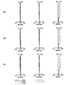
- Example 2 Layout of the zoom lens system of Example 2 at the wide-angle end at an object distance of 900 mm Vertical aberration diagram of the zoom lens system of Example 2 at an object distance of 900 mm. Vertical aberration diagram of the zoom lens system of Example 2 at an object distance of 600 mm. Vertical aberration diagram of the zoom lens system of Example 2 at an object distance of 2400 mm. Arrangement diagram showing the optical path at the wide-angle end at an object distance of 900 mm in the zoom lens system of Embodiment 3. Arrangement drawing of the wide-angle end at an object distance of 900 mm in the zoom lens system of Embodiment 3. Vertical aberration diagram of the zoom lens system of Example 3 at an object distance of 900 mm.
- a projector in which an optical system projects image light of an original image S obtained by spatially modulating incident light by an image forming element such as a liquid crystal or DMD (digital micromirror device) based on an image signal on a screen.
- an image forming element such as a liquid crystal or DMD (digital micromirror device)
- the optical system according to the present disclosure can be used to arrange a screen (not shown) on the extension line on the enlargement side and enlarge the original image S on the image forming element arranged on the reduction side to project the original image S on the screen.
- the optical system according to the present disclosure condenses light emitted from an object located on the extension line on the enlargement side and forms an optical image of the object on the image pickup surface of the image pickup element arranged on the reduction side. Is also available.
- Embodiment 1 of the present disclosure will be described with reference to FIGS. 1 to 15.
- a zoom lens system will be described as an example of the optical system.
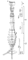
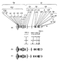
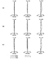
- 1, 6, and 11 are layout diagrams showing the optical paths at the wide-angle end at an object distance of 900 mm in the zoom lens systems according to Examples 1 to 3.
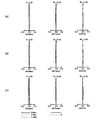
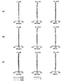
- 2(a), 7(a), and 12(a) are layout diagrams of the zoom lens systems according to Examples 1 to 3 at the wide-angle end at an object distance of 900 mm.
- 2(b), 7(b) and 12(b) show lens layout diagrams at the intermediate position of the zoom lens system.
- 2(c), 7(c) and 12(c) are lens arrangement diagrams at the telephoto end of the zoom lens system.
- the zoom lens system has each state of wide-angle end, intermediate position, and telephoto end.
- the wide-angle end is the shortest focal length state in which the entire system has the shortest focal length fw.
- the intermediate position is an intermediate focal length state between the wide-angle end and the telephoto end.
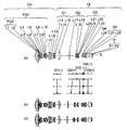
- the zoom lens system according to Example 1 includes a first focus lens group FG1, a second focus lens group FG2, a first lens group G1 having negative power, and a positive power.
- the second lens group G2 to the fourth lens group G4 are included.
- the zoom lens system according to Example 2 has a first focus lens group FG1, a second focus lens group FG2, a first lens group G1 having negative power, and positive power. It includes a second lens group G2, a third lens group G3 having negative power, and a fourth lens group G4 having positive power.
- the zoom lens system according to Example 3 has a first focus lens group FG1, a second focus lens group FG2, a first lens group G1 having negative power, and positive power. It includes a second lens group G2, a third lens group G3 having negative power, a fourth lens group G4 having positive power, and a fifth lens group G5 having positive power.
- the first to fifth lens groups G1 to G5 can be fixed or moved independently of each other.
- the symbols (+) and ( ⁇ ) attached to the reference numerals of the lens groups G1 to G5 indicate the positive and negative of the power of the lens groups G1 to G5.
- the broken line arrows shown between each figure (a) and each figure (b) indicate the first lens group G1 to the fifth lens in each state of the wide-angle end, the intermediate position, and the telephoto end in order from the top in the figure. It is a straight line obtained by connecting the positions of the group G5. The wide-angle end and the intermediate position, and the intermediate position and the telephoto end are simply connected by a straight line, which is different from the actual movement of the lens groups G1 to G5.
- the first focus lens group FG1 can move along the optical axis.
- the second focus lens group FG2 can be moved along the optical axis.
- the image forming position on the left side (that is, the enlargement conjugate point) is located on the left side
- the image forming position on the right side that is, the reduction conjugate point
- the straight line described on the most reduction side represents the position of the original image S
- the optical element P is located on the enlargement side of the original image S.
- the optical element P represents an optical element such as a prism for color separation and color synthesis, an optical filter, a parallel plate glass, a crystal low pass filter, an infrared cut filter, and the like.
- the zoom lens systems according to Examples 1 to 3 internally have intermediate image formation positions MI that are respectively conjugate to the enlargement-side enlargement conjugate point and the reduction-side reduction conjugate point.
- the enlargement optical system Op is arranged on the enlargement side of the intermediate image formation position MI
- the relay optical system Ol is arranged on the reduction side of the intermediate image formation position MI.
- the magnifying optical system Op may have a plurality of focus lens groups, and in Examples 1 to 3, the first focus lens group FG1 and the second focus lens group FG2, and the lens elements L11, L12 or lenses that do not become the focus lens group.
- the case where elements L11, L12, and L13 are included is illustrated.
- the first focus lens group FG1 is composed of a plurality of (for example, 10) first lens element L1 to tenth lens element L10. Then, the first focus lens group FG1 performs focus adjustment when the object distance changes.
- the second focus lens group FG2 is composed of a part of lens elements of the first focus lens group FG1, for example, one or two lens elements including the first lens element L1. Then, the second focus lens group FG2 corrects the field curvature aberration after the first focus lens group FG1 performs the focus adjustment.
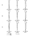
- Each longitudinal aberration diagram shows spherical aberration (SA (mm)), astigmatism (AST (mm)), and distortion (DIS (%)) in order from the left side.
- the vertical axis represents the F number (indicated by F in the figure)
- the solid line is the d line (d-line)
- the short dashed line is the F line (F-line)
- the long dashed line is the C line (C- line) characteristics.
- the vertical axis represents the image height
- the solid line represents the sagittal plane (indicated by s in the figure)
- the broken line represents the meridional plane (indicated by m in the figure).
- the vertical axis represents the image height.
- the distortion aberration represents the distortion aberration for equidistant projection.
- the zoom lens system according to Example 1 includes a magnifying optical system Op and a relay optical system Ol.
- the magnifying optical system Op includes a first focus lens group FG1 and a second focus lens group FG2.
- the relay optical system Ol includes a first lens group G1 to a fourth lens group G4 in order from the enlargement side to the reduction side.
- the first focus lens group FG1 is composed of the first lens element L1 to the tenth lens element L10 in order from the enlargement side to the reduction side, and includes the surface 1 to the surface 20 (each surface number will be described later in a numerical example See).
- the first lens element L1 has a negative meniscus shape with a convex surface facing the enlargement side.
- the second lens element L2 has a negative meniscus shape with the convex surface facing the enlargement side.
- the third lens element L3 has a positive meniscus shape with the convex surface facing the enlargement side.
- the fourth lens element L4 has a positive meniscus shape with the convex surface facing the reduction side.
- the fifth lens element L5 has a positive meniscus shape with a convex surface facing the reduction side.
- the sixth lens element L6 has a negative meniscus shape with the convex surface facing the reduction side.
- the seventh lens element L7 has a biconvex shape.
- the eighth lens element L8 has a biconvex shape.
- the ninth lens element L9 has a biconvex shape.
- the tenth lens element L10 has a biconcave shape.
- the second focus lens group FG2 is composed of only the first lens element L1.
- the magnifying optical system Op has an eleventh lens element L11 to a twelfth lens element L12 on the reduction side of the first focus lens group FG1 in order from the enlargement side to the reduction side, and includes surfaces 21 to 24.
- the eleventh lens element L11 has a biconvex shape.
- the twelfth lens element L12 has a positive meniscus shape with a convex surface facing the enlargement side.
- the first lens group G1 has negative power, is composed of the thirteenth lens element L13 to the fifteenth lens element L15 in order from the enlargement side to the reduction side, and includes the surfaces 25 to 30.
- the thirteenth lens element L13 has a negative meniscus shape with the convex surface facing the reduction side.
- the 14th lens element L14 has a negative meniscus shape with the convex surface facing the enlargement side.
- the fifteenth lens element L15 has a positive meniscus shape with a convex surface facing the reduction side.
- the second lens group G2 has positive power, and is composed of the sixteenth lens element L16 to the eighteenth lens element L18 in order from the enlargement side to the reduction side, and includes the surfaces 31 to 36.
- the 16th lens element L16 has a biconvex shape.
- the seventeenth lens element L17 has a biconcave shape.
- the eighteenth lens element L18 has a biconvex shape.
- the third lens group G3 has a positive power, is composed of the nineteenth lens element L19, and includes surfaces 37 to 38.
- the nineteenth lens element L19 has a positive meniscus shape with a convex surface facing the enlargement side.
- the fourth lens group G4 has a positive power, is composed of the twentieth lens element L20 to the twenty-fifth lens element L25 in order from the enlargement side to the reduction side, and includes the surfaces 39 to 51.
- the twentieth lens element L20 has a negative meniscus shape with a convex surface facing the enlargement side.
- the twenty-first lens element L21 has a biconcave shape.
- the 22nd lens element L22 has a biconvex shape.
- the 23rd lens element L23 has a biconvex shape.
- the 24th lens element L24 has a negative meniscus shape with a convex surface facing the enlargement side.
- the 25th lens element L25 has a biconvex shape.
- the first focus lens group (the first lens element L1 to the tenth lens element L10) moves along the optical axis when adjusting the focusing, so it can be called a focusing adjustment lens group. ..
- the second focus lens group (first lens element L1) moves along the optical axis to correct the field curvature aberration when adjusting the field curvature amount, and is therefore referred to as a field curvature correction lens group. be able to.
- Example 2 illustrates a zoom lens system in which the third lens group G3 has a negative power.
- the zoom lens system according to Example 2 includes a magnifying optical system Op and a relay optical system Ol.
- the magnifying optical system Op includes a first focus lens group FG1 and a second focus lens group FG2.
- the relay optical system Ol includes a first lens group G1 to a fourth lens group G4 in order from the enlargement side to the reduction side.
- the first focus lens group FG1 is composed of the first lens element L1 to the tenth lens element L10 in order from the enlargement side to the reduction side, and includes the surfaces 1 to 20.
- the first lens element L1 has a negative meniscus shape with a convex surface facing the enlargement side.
- the second lens element L2 has a positive meniscus shape with the convex surface facing the enlargement side.
- the third lens element L3 has a negative meniscus shape with a convex surface facing the enlargement side.
- the fourth lens element L4 has a negative meniscus shape with the convex surface facing the enlargement side.
- the fifth lens element L5 has a positive meniscus shape with a convex surface facing the enlargement side.
- the sixth lens element L6 has a positive meniscus shape with the convex surface facing the reduction side.
- the seventh lens element L7 has a biconvex shape.
- the eighth lens element L8 has a biconcave shape.
- the ninth lens element L9 has a positive meniscus shape with the convex surface facing the reduction side.
- the tenth lens element L10 has a positive meniscus shape with the convex surface facing the reduction side.
- the second focus lens group FG2 is composed of a first lens element L1 and a second lens element L2.
- Magnification optical system Op has eleventh lens element L11 to thirteenth lens element L13 on the reduction side of first focus lens group FG1 in order from the enlargement side to the reduction side, and includes surfaces 21 to 26.
- the eleventh lens element L11 has a biconvex shape.
- the twelfth lens element L12 has a biconvex shape.
- the thirteenth lens element L13 has a positive meniscus shape with the convex surface facing the enlargement side.
- the first lens group G1 has negative power, is composed of the fourteenth lens element L14 to the sixteenth lens element L16 in order from the enlargement side to the reduction side, and includes the surfaces 27 to 32.
- the fourteenth lens element L14 has a biconcave shape.
- the fifteenth lens element L15 has a negative meniscus shape with a convex surface facing the enlargement side.
- the 16th lens element L16 has a positive meniscus shape with the convex surface facing the reduction side.
- the second lens group G2 has positive power, and is composed of the seventeenth lens element L17 to the nineteenth lens element L19 in order from the enlargement side to the reduction side, and includes the surfaces 33 to 38.
- the seventeenth lens element L17 has a biconvex shape.
- the eighteenth lens element L18 has a biconcave shape.
- the nineteenth lens element L19 has a biconvex shape.
- the third lens group G3 has negative power, is composed of the twentieth lens element L20 to the twenty-third lens element L23 in order from the enlargement side to the reduction side, and includes the surfaces 39 to 47.
- the twentieth lens element L20 has a positive meniscus shape with a convex surface facing the enlargement side.
- the 21st lens element L21 has a negative meniscus shape with the convex surface facing the enlargement side.
- the 22nd lens element L22 has a biconcave shape.
- the 23rd lens element L23 has a biconvex shape.
- the fourth lens group G4 has positive power, and is composed of the 24th lens element L24 to the 26th lens element L26 in order from the enlargement side to the reduction side, and includes the surfaces 48 to 53.
- the 24th lens element L24 has a biconvex shape.
- the 25th lens element L25 has a negative meniscus shape with the convex surface facing the enlargement side.
- the 26th lens element L26 has a biconvex shape.
- the first focus lens group (the first lens element L1 to the tenth lens element L10) moves along the optical axis when adjusting the focusing, so it can be called a focusing adjustment lens group. ..
- the second focus lens group (the first lens element L1 and the second lens element L2) moves along the optical axis to correct the field curvature aberration when adjusting the field curvature amount. It can be called a curvature correction lens group.
- optical elements P1 and P2 having an optical power of zero are arranged on the reduction side of the relay optical system Ol, and these correspond to the optical element P.
- Example 3 illustrates a zoom lens system in which the relay optical system Ol is composed of the first lens group G1 to the fifth lens group G5.
- the zoom lens system according to Example 3 includes a magnifying optical system Op and a relay optical system Ol.
- the magnifying optical system Op includes a first focus lens group FG1 and a second focus lens group FG2.
- the relay optical system Ol includes a first lens group G1 to a fifth lens group G5 in order from the enlargement side to the reduction side.
- the first focus lens group FG1 is composed of the first lens element L1 to the tenth lens element L10 in order from the enlargement side to the reduction side, and includes the surfaces 1 to 20.
- the first lens element L1 has a negative meniscus shape with a convex surface facing the enlargement side.
- the second lens element L2 has a positive meniscus shape with the convex surface facing the enlargement side.
- the third lens element L3 has a negative meniscus shape with a convex surface facing the enlargement side.
- the fourth lens element L4 has a negative meniscus shape with the convex surface facing the enlargement side.
- the fifth lens element L5 has a positive meniscus shape with a convex surface facing the enlargement side.
- the sixth lens element L6 has a positive meniscus shape with the convex surface facing the reduction side.
- the seventh lens element L7 has a biconvex shape.
- the eighth lens element L8 has a biconcave shape.
- the ninth lens element L9 has a positive meniscus shape with the convex surface facing the reduction side.
- the tenth lens element L10 has a positive meniscus shape with the convex surface facing the reduction side.
- the second focus lens group FG2 is composed of a first lens element L1 and a second lens element L2.
- Magnification optical system Op has eleventh lens element L11 to thirteenth lens element L13 on the reduction side of first focus lens group FG1 in order from the enlargement side to the reduction side, and includes surfaces 21 to 26.
- the eleventh lens element L11 has a biconvex shape.
- the twelfth lens element L12 has a biconvex shape.
- the thirteenth lens element L13 has a positive meniscus shape with the convex surface facing the enlargement side.
- the first lens group G1 has negative power, is composed of the fourteenth lens element L14 to the sixteenth lens element L16 in order from the enlargement side to the reduction side, and includes the surfaces 27 to 32.
- the fourteenth lens element L14 has a biconcave shape.
- the fifteenth lens element L15 has a negative meniscus shape with a convex surface facing the enlargement side.
- the 16th lens element L16 has a positive meniscus shape with the convex surface facing the reduction side.
- the second lens group G2 has positive power, and is composed of the seventeenth lens element L17 to the nineteenth lens element L19 in order from the enlargement side to the reduction side, and includes the surfaces 33 to 38.
- the seventeenth lens element L17 has a biconvex shape.
- the eighteenth lens element L18 has a biconcave shape.
- the nineteenth lens element L19 has a biconvex shape.
- the third lens group G3 has negative power, is composed of the twentieth lens element L20 to the twenty-third lens element L23 in order from the enlargement side to the reduction side, and includes the surfaces 39 to 47.
- the twentieth lens element L20 has a positive meniscus shape with a convex surface facing the enlargement side.
- the 21st lens element L21 has a negative meniscus shape with the convex surface facing the enlargement side.
- the 22nd lens element L22 has a biconcave shape.
- the 23rd lens element L23 has a biconvex shape.
- the fourth lens group G4 has a positive power, is composed of the 24th lens element L24, and includes surfaces 48 to 49.
- the 24th lens element L24 has a biconvex shape.
- the fifth lens group G5 has positive power, and is composed of the 25th lens element L25 to the 26th lens element L26 in order from the enlargement side to the reduction side, and includes the surfaces 50 to 53.
- the 25th lens element L25 has a negative meniscus shape with the convex surface facing the enlargement side.
- the 26th lens element L26 has a biconvex shape.
- the first focus lens group (the first lens element L1 to the tenth lens element L10) moves along the optical axis when adjusting the focusing, so it can be called a focusing adjustment lens group. ..
- the second focus lens group (the first lens element L1 and the second lens element L2) moves along the optical axis to correct the field curvature aberration when adjusting the field curvature amount. It can be called a curvature correction lens group.
- the zoom lens system according to the present embodiment internally has the intermediate image formation position MI that is respectively conjugate with the enlargement-side enlargement conjugate point and the reduction-side reduction conjugate point.
- the zoom lens systems according to Examples 1 to 3 are located on the reduction side from the intermediate image formation position MI and the enlargement optical system Op configured by a plurality of lens elements located on the enlargement side from the intermediate image formation position MI.
- a relay optical system Ol including a plurality of lens elements.
- the lens group on the magnifying side of the lens element is a magnifying optical system Op
- the lens group on the reducing side of the lens element at the intermediate imaging position MI is It is a relay optical system Ol.
- the zoom lens system according to this embodiment may be configured as an interchangeable lens that can be detachably attached to a main body device such as an image projection device or an imaging device described later.
- the lens for adjusting the amount of curvature of field at the enlargement conjugate point on the enlargement side for example, the first lens element L1 and the like, is configured so that the position in the optical axis direction can be adjusted after being attached to the main body device.
- the zoom lens systems according to Examples 1 to 3 are not only lens elements having optical power but also elements having optical power of zero or substantially zero, such as mirrors, diaphragms, masks, cover glasses, filters, It may include optical elements such as a prism, a wave plate, and a polarizing element.
- the zoom lens system according to the present embodiment is an optical system that internally has an intermediate imaging position MI that is respectively conjugated with the enlargement-side conjugate point and the reduction-side reduction conjugate point.
- a magnifying optical system Op having A (A: an integer of 3 or more) number of lens elements and located on the magnifying side from the intermediate imaging position MI; B (B: an integer of 2 or more) lens elements, and a relay optical system Ol located on the reduction side of the intermediate image formation position MI.
- the first lens group G1 including b lens elements (b:1 or more and less than B) located first from the enlargement side may have negative power.
- the angle of the light ray with respect to the optical axis becomes smaller on the reduction side from the intermediate image formation position MI, so that it becomes easy to widen the angle. Further, since the distortion aberration can be corrected by the first lens group G1 having negative power, the load of correction by the first lens L1 located closest to the magnification side can be reduced, and the size can be reduced. Further, since the distortion aberration can be corrected without using an aspherical lens for the first lens L1, the manufacturing cost can be reduced.
- the first lens group G1 may be fixed during zooming.
- the magnifying optical system Op is fixed, and a part or all of the lens elements of the relay optical system Ol except the first lens group G1 have an optical axis. You may move along.
- zooming operation can be performed without moving the magnifying optical system Op, which is large in size and weight, so that the zoom mechanism can be made smaller and lighter.
- the zoom lens system according to the present embodiment may satisfy the following condition (1). 1 ⁇ fs1/fw ⁇ 100 (1) here, fs1: focal length of the first lens group G1 fw: focal length of the entire system at the wide-angle end.
- the condition (1) is a conditional expression for defining the relationship between the focal length of the first lens group G1 and the focal length of the entire system at the wide-angle end.
- the zoom lens system according to the present embodiment is a lens that is positioned first from the reduction side in the relay optical system Ol during focusing (the 25th lens element L25 of Example 1, the 26th lens of Examples 2 and 3). (Corresponding to the element L26) may be fixed, and at least the first lens element L1 located at the first position from the expansion side in the expansion optical system Op may move along the optical axis.
- the magnifying optical system Op includes a first lens element L1 and a first focus lens group FG1 including a (a: 3 or more and less than A) lens elements.
- a 3 or more and less than A
- the following condition (2) may be satisfied. 2 ⁇
- the condition (2) is a conditional expression for defining the relationship between the focal length of the first focus lens group FG1 and the focal length of the entire system at the wide-angle end.
- the zoom lens system according to the present embodiment may include a second focus lens group FG2 in the magnifying optical system Op that moves along the optical axis after focusing to correct the field curvature aberration.
- the second focus lens group FG2 includes the first lens element L1 and is composed of one or two lens elements.
- the magnifying optical system Op includes a first lens element L1 and a second focus lens group FG2 including one or two lens elements,
- the following condition (3) may be satisfied. 18 ⁇
- the condition (3) is a conditional expression for defining the relationship between the focal length of the second focus lens group FG2 and the focal length of the entire system at the wide-angle end.
- the relay optical system Ol may be fixed and some or all of the lens elements in the magnifying optical system Op may move along the optical axis during focusing.
- the zoom lens system according to the present embodiment may satisfy the following condition (4).
- ff focal length of magnifying optical system
- Op fw focal length of the entire system at the wide-angle end.
- Condition (4) is a conditional expression for defining the relationship between the focal length of the magnifying optical system Op and the focal length of the entire system at the wide-angle end.
- the zoom lens system according to the present embodiment may satisfy the following condition (5). 1.5 ⁇
- Requirement (5) is a conditional expression for defining the relationship between the focal length of the relay optical system Ol at the wide-angle end and the focal length of the entire system at the wide-angle end.
- the relay optical system includes a) a first lens group having negative power, a second lens group having positive power, and a positive lens group arranged in order from the enlargement side to the reduction side.
- the zoom lens system according to the present embodiment may satisfy the following condition (6).
- Condition (6) is a conditional expression for defining the maximum half angle of view at the wide-angle end.
- Z Distance from a point on the aspherical surface whose height from the optical axis is h to the tangent plane of the aspherical surface apex, h: height from the optical axis, r: vertex curvature radius, ⁇ : conic constant, An: An aspherical coefficient of order n.
- Table 13 shows the corresponding values of each conditional expression in each numerical example.
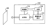
- FIG. 16 is a block diagram showing an example of an image projection device according to the present disclosure.
- the image projection apparatus 100 includes the optical system 1 disclosed in the first embodiment, an image forming element 101, a light source 102, a control unit 110, and the like.
- the image forming element 101 is composed of liquid crystal, DMD, etc., and generates an image to be projected on the screen SR via the optical system 1.
- the light source 102 includes an LED (light emitting diode), a laser, and the like, and supplies light to the image forming element 101.
- the control unit 110 is configured by a CPU or MPU, and controls the entire device and each component.
- the optical system 1 may be configured as an interchangeable lens that can be detachably attached to the image projection apparatus 100. In this case, a device in which the optical system 1 is removed from the image projection device 100 is an example of the main body device.
- the image projection apparatus 100 described above can realize a compact and wide-angle zoom function while reducing costs.
- FIG. 17 is a block diagram showing an example of an imaging device according to the present disclosure.
- the image pickup apparatus 200 includes the optical system 1 disclosed in the first embodiment, an image pickup element 201, a control unit 210, and the like.
- the image pickup device 201 is composed of a CCD (charge coupled device) image sensor, a CMOS image sensor, or the like, and receives an optical image of the object OBJ formed by the optical system 1 and converts it into an electric image signal.
- the control unit 110 is configured by a CPU or MPU, and controls the entire device and each component.
- the optical system 1 may be configured as an interchangeable lens that can be detachably attached to the imaging device 200. In this case, an apparatus in which the optical system 1 is removed from the image pickup apparatus 200 is an example of the main body apparatus.
- the image pickup apparatus 200 described above can realize a small-sized and wide-angle zoom function while reducing costs.
- the present disclosure is applicable to image projection devices such as projectors and head-up displays, and imaging devices such as digital still cameras, digital video cameras, surveillance cameras in surveillance systems, web cameras, and vehicle-mounted cameras.
- imaging devices such as digital still cameras, digital video cameras, surveillance cameras in surveillance systems, web cameras, and vehicle-mounted cameras.
- the present disclosure is applicable to optical systems that require high image quality, such as projectors, digital still camera systems, and digital video camera systems.
Landscapes
- Physics & Mathematics (AREA)
- General Physics & Mathematics (AREA)
- Optics & Photonics (AREA)
- Lenses (AREA)
- Projection Apparatus (AREA)
Abstract
Description
A(A:3以上の整数)枚のレンズ素子を有し、前記中間結像位置より前記拡大側に位置する拡大光学系と、
B(B:2以上の整数)枚のレンズ素子を有し、前記中間結像位置より前記縮小側に位置するリレー光学系と、を備え、
前記リレー光学系において前記拡大側から1番目に位置するb枚(b:1以上、かつ、B未満)のレンズ素子からなる第1レンズ群が負のパワーを有する。
以下、図1~図15を用いて本開示の実施形態1を説明する。ここでは、光学系の一例としてズームレンズ系について説明する。
図1と図2に示すように、実施例1に係るズームレンズ系は、拡大光学系Opとリレー光学系Olとを備える。拡大光学系Opは、第1フォーカスレンズ群FG1、第2フォーカスレンズ群FG2を含む。リレー光学系Olは、拡大側から縮小側へと順に、第1レンズ群G1~第4レンズ群G4を含む。
実施例1では、リレー光学系Olにおける第3レンズ群G3のパワーが正であるが、本実施形態はこれに限定されない。実施例2では、第3レンズ群G3のパワーが負であるズームレンズ系を例示する。図6と図7に示すように、実施例2に係るズームレンズ系は、拡大光学系Opとリレー光学系Olとを備える。拡大光学系Opは、第1フォーカスレンズ群FG1、第2フォーカスレンズ群FG2を含む。リレー光学系Olは、拡大側から縮小側へと順に、第1レンズ群G1~第4レンズ群G4を含む。
実施例1、2では、リレー光学系Olが第1レンズ群G1~第4レンズ群G4で構成されるが、本実施形態はこれに限定されない。実施例3では、リレー光学系Olが第1レンズ群G1~第5レンズ群G5で構成されるズームレンズ系を例示する。図11と図12に示すように、実施例3に係るズームレンズ系は、拡大光学系Opとリレー光学系Olとを備える。拡大光学系Opは、第1フォーカスレンズ群FG1、第2フォーカスレンズ群FG2を含む。リレー光学系Olは、拡大側から縮小側へと順に、第1レンズ群G1~第5レンズ群G5を含む。
以上の実施例1~3のように、本実施形態に係るズームレンズ系は、拡大側の拡大共役点及び縮小側の縮小共役点とそれぞれ共役である中間結像位置MIを内部に有する。また、実施例1~3に係るズームレンズ系は、中間結像位置MIより拡大側に位置する複数のレンズ素子で構成される拡大光学系Opと、中間結像位置MIから縮小側に位置する複数のレンズ素子で構成されるリレー光学系Olとを備える。なお、中間結像位置MIがレンズ素子内部にある場合は、そのレンズ素子よりも拡大側にあるレンズ群が拡大光学系Op、中間結像位置MIにあるレンズ素子から縮小側にあるレンズ群がリレー光学系Olである。リレー光学系Olにより原画像を中間結像することで、諸収差を補正しやすく、特に倍率色収差などの補正が容易になる。
A(A:3以上の整数)枚のレンズ素子を有し、前記中間結像位置MIより前記拡大側に位置する拡大光学系Opと、
B(B:2以上の整数)枚のレンズ素子を有し、前記中間結像位置MIより前記縮小側に位置するリレー光学系Olと、を備え、
前記リレー光学系Olにおいて前記拡大側から1番目に位置するb枚(b:1以上、かつ、B未満)のレンズ素子からなる第1レンズ群G1が負のパワーを有してもよい。
1<fs1/fw<100 ・・・(1)
ここで、
fs1:第1レンズ群G1の焦点距離
fw:広角端の全系の焦点距離
である。
fs1/fw>10 ・・・(1A)
fs1/fw<50 ・・・(1B)
以下の条件(2)を満足してもよい。
2<|fFG1/fw|<10 ・・・(2)
ここで、
fFG1:第1フォーカスレンズ群FG1の焦点距離
fw:広角端の全系の焦点距離
である。
|fFG1/fw|>4 ・・・(2A)
|fFG1/fw|<8 ・・・(2B)
以下の条件(3)を満足してもよい。
18<|fFG2/fw|<120 ・・・(3)
ここで、
fFG2:第2フォーカスレンズ群FG2の焦点距離
である。
|fFG2/fw|>20 ・・・(3A)
|fFG2/fw|<100 ・・・(3B)
1.0<|ff/fw|<5 ・・・(4)
ここで、
ff:拡大光学系Opの焦点距離
fw:広角端の全系の焦点距離
である。
1.5<|fr/fw|<5 ・・・(5)
ここで、
fr:広角端でのリレー光学系Olの焦点距離
fw:広角端の全系の焦点距離
である。
|ω|>60 ・・・(6)
ここで、
ω:広角端の最大の半画角
である。

Z:光軸からの高さがhの非球面上の点から、非球面頂点の接平面までの距離、
h:光軸からの高さ、
r:頂点曲率半径、
κ:円錐定数、
An:n次の非球面係数
である。
数値実施例1(実施例1に対応)のズームレンズ系について、面データを表1に示し、各種データを表2に示し、単レンズデータを表3に示し、ズームレンズ群データを表4に示す。
面データ
面番号 r d nd vd
物面 ∞
1 70.95120 3.50000 1.83481 42.7
2 43.80140 16.27120
3* 48.65870 3.50000 1.51633 64.1
4* 15.20610 23.79150
5 525.11730 25.95590 1.61800 63.4
6 881.51500 2.82520
7* -42.49710 5.28490 1.58313 59.4
8* -22.14280 0.20020
9 -89.95850 9.47620 1.55032 75.5
10 -23.16540 0.31530
11 -23.08340 2.00000 1.80810 22.8
12 -4607.97460 0.43500
13 1659.29130 13.90850 1.59282 68.6
14 -36.96930 0.74230
15 10266.35840 11.25340 1.59282 68.6
16 -64.36810 0.20400
17 209.49060 16.08830 1.43700 95.1
18 -57.39020 0.76370
19 -54.79270 2.50000 1.59270 35.4
20 137.03320 13.76270
21 126.83430 15.25190 1.86966 20.0
22 -154.46520 0.72390
23 43.32520 12.47050 1.86966 20.0
24 68.40260 24.15100
25 -57.49090 20.82320 1.85883 30.0
26 -63.89760 0.36320
27* -667.89390 3.00000 1.80998 40.9
28* 26.91440 66.00190
29 -1254.61490 4.85070 1.80420 46.5
30 -93.95470 可変
31 112.01550 3.95340 1.85883 30.0
32 -565.79860 3.05970
33 -57.17390 2.00000 1.65412 39.7
34 54.08470 0.21150
35 53.83790 9.00580 1.55032 75.5
36 -49.57790 可変
37 27.77070 6.15940 1.59270 35.4
38 107.60070 可変
39 44.46160 1.50000 1.51680 64.2
40 19.25470 5.29340
41(絞り) ∞ 17.26720
42 -23.71550 1.50000 1.80610 33.3
43 52.17970 0.50880
44 68.52930 6.18540 1.43700 95.1
45 -29.75470 3.33090
46 61.64940 9.52630 1.49700 81.6
47 -41.29800 3.03060
48 58.93560 2.00000 1.79952 42.2
49 30.88120 0.57170
50 32.83840 11.91270 1.49700 81.6
51 -50.86200 20.70000
52 ∞ 25.00000 1.58913 61.3
53 ∞ 1.00000
54 ∞ 3.00000 1.50847 61.2
55 ∞ BF
像面 ∞
非球面データ
第3面
K= 0.00000E+00, A4= 7.78139E-07, A6= 6.22294E-11, A8= 0.00000E+00
A10= 0.00000E+00, A12= 0.00000E+00
第4面
K=-7.29002E-01, A4=-1.03008E-05, A6=-1.02602E-08, A8= 9.72136E-12
A10=-3.41056E-14, A12= 2.69059E-18
第7面
K= 0.00000E+00, A4=-6.65447E-07, A6=-2.98202E-09, A8=-2.03755E-11
A10= 0.00000E+00, A12= 0.00000E+00
第8面
K= 0.00000E+00, A4= 7.29220E-06, A6= 1.14483E-08, A8= 0.00000E+00
A10= 0.00000E+00, A12= 0.00000E+00
第27面
K= 0.00000E+00, A4= 8.16936E-06, A6=-3.75272E-09, A8= 1.28334E-12
A10= 0.00000E+00, A12= 0.00000E+00
第28面
K= 0.00000E+00, A4=-3.87007E-07, A6=-5.16193E-09, A8=-7.44821E-13
A10= 0.00000E+00, A12= 0.00000E+00
各種データ(物体距離900mm)
ズーム比 1.10484
広角 中間 望遠
焦点距離 -5.6818 -5.8914 -6.2774
Fナンバー -1.99587 -1.99582 -1.99555
画角 -63.8849 -63.0958 -61.6670
像高 11.6200 11.6200 11.6200
レンズ全長 495.3918 495.3906 495.3998
BF 1.01393 1.01268 1.02179
d30 52.8021 47.7296 38.9031
d36 2.0019 7.1524 16.1022
d38 2.4425 2.3645 2.2413
各種データ(物体距離600mm)
d2 16.0985 14.6895 16.7232
d20 14.4198 14.3121 14.4000
各種データ(物体距離2400mm)
d2 14.8217 15.7612 13.5430
d20 13.0724 13.0993 13.2365
単レンズデータ
レンズ 始面 焦点距離
1 1 -145.6613
2 3 -44.4197
3 5 2044.7879
4 7 72.3613
5 9 53.9752
6 11 -28.7146
7 13 61.1889
8 15 107.9460
9 17 105.0118
10 19 -65.7208
11 21 82.1563
12 23 110.3604
13 25 1330.7619
14 27 -31.8798
15 29 126.0528
16 31 109.1672
17 33 -42.1899
18 35 48.3959
19 37 61.3910
20 39 -67.0776
21 42 -20.0501
22 44 48.4015
23 46 51.3381
24 48 -83.7958
25 50 42.1420
ズームレンズ群データ
群 始面 焦点距離
0 1 14.480
1 25 -143.417
2 31 135.991
3 37 61.391
4 39 49.004
数値実施例2(実施例2に対応)のズームレンズ系について、面データを表5に示し、各種データを表6に示し、単レンズデータを表7に示し、ズームレンズ群データを表8に示す。
面データ
面番号 r d nd vd
物面 ∞
1 77.74810 4.50000 1.90366 31.3
2 45.02530 13.89470
3 95.07980 7.46330 1.72342 38.0
4 255.20960 1.20000
5 71.36640 2.50000 1.80420 46.5
6 21.00780 4.52040
7* 23.39160 3.20000 1.80998 40.9
8* 11.55090 8.10340
9 26.88930 4.96960 1.80610 33.3
10 272.90290 1.33220
11 -77.54890 17.11470 1.61800 63.4
12 -42.27460 0.20000
13 35.18170 6.05530 1.49700 81.6
14 -43.00420 1.78790
15 -24.99520 1.00000 1.86966 20.0
16 109.98400 1.06550
17 -472.83790 8.47180 1.49700 81.6
18 -19.65040 0.20000
19* -37.26990 5.20710 1.68948 31.0
20* -25.00000 3.49930
21 63.03220 13.32980 1.49700 81.6
22 -75.40430 0.20000
23 81.08640 7.34610 1.92286 20.9
24 -873.63600 0.20000
25 27.96110 8.55070 1.92286 20.9
26 46.18150 12.93050
27 -58.54250 3.48510 1.80809 22.8
28 31.42850 5.02200
29* 500.00000 3.00000 1.68948 31.0
30* 21.84910 30.57940
31 -112.49700 12.20850 1.83481 42.7
32 -39.71210 可変
33 179.50050 5.67980 1.80610 33.3
34 -200.27300 43.18710
35 -40.17420 1.50000 1.73800 32.3
36 69.21510 2.88320
37 88.10550 7.76180 1.55032 75.5
38 -33.88690 可変
39 26.29340 4.96630 1.59270 35.4
40 61.82780 1.92800
41(絞り) ∞ 0.25840
42 25.66670 1.50000 1.56883 56.0
43 17.77300 27.75870
44 -24.29060 1.00000 1.73800 32.3
45 591.07320 0.20000
46 129.09770 6.83160 1.43700 95.1
47 -29.68620 可変
48 52.76500 7.94360 1.49700 81.6
49 -52.76500 0.20000
50 38.76670 1.50000 1.73800 32.3
51 22.52490 1.42840
52 24.36750 9.06640 1.43700 95.1
53 -270.40960 可変
54 ∞ 25.00000 1.58913 61.3
55 ∞ 1.00000
56 ∞ 3.00000 1.50847 61.2
57 ∞ BF
像面 ∞
非球面データ
第7面
K= 0.00000E+00, A4=-9.46159E-06, A6=-5.93665E-08, A8= 2.59365E-11
A10= 0.00000E+00, A12= 0.00000E+00
第8面
K=-8.29046E-01, A4=-2.04827E-05, A6=-1.44054E-07, A8=-2.39467E-10
A10= 1.48290E-12, A12= 0.00000E+00
第19面
K= 0.00000E+00, A4= 1.63319E-05, A6=-1.25916E-07, A8= 2.56894E-10
A10=-8.18906E-13, A12= 2.03635E-15
第20面
K= 0.00000E+00, A4= 2.92131E-05, A6=-2.07775E-08, A8=-1.05659E-10
A10= 3.78200E-13, A12=-2.31438E-17
第29面
K= 0.00000E+00, A4= 6.25077E-05, A6=-1.55377E-07, A8= 8.15590E-11
A10= 0.00000E+00, A12= 0.00000E+00
第30面
K= 0.00000E+00, A4= 3.16767E-06, A6=-1.09870E-07, A8= 3.77124E-11
A10= 0.00000E+00, A12= 0.00000E+00
各種データ(物体距離900mm)
ズーム比 1.07079
広角 中間 望遠
焦点距離 -4.1412 -4.2730 -4.4343
Fナンバー -2.00004 -2.00185 -2.00526
画角 -70.0280 -69.4752 -68.8020
像高 11.6200 11.6200 11.6200
レンズ全長 430.0116 430.0199 430.0233
BF 1.01173 1.02018 1.02352
d32 62.6930 55.7106 47.0668
d38 2.0067 8.9890 17.6328
d47 3.8696 3.4418 2.8476
d53 12.7000 13.1277 13.7220
各種データ(物体距離600mm)
d4 1.1249 0.9541 1.0709
d20 3.6565 3.5501 3.6513
各種データ(物体距離2400mm)
d4 1.4128 1.4016 1.3543
d20 3.3687 3.3440 3.3182
単レンズデータ
レンズ 始面 焦点距離
1 1 -126.6514
2 3 205.4518
3 5 -37.8578
4 7 -32.0484
5 9 36.6726
6 11 126.8745
7 13 39.9630
8 15 -23.3386
9 17 40.9982
10 19 93.8787
11 21 71.3615
12 23 80.6998
13 25 62.6772
14 27 -24.8759
15 29 -33.2223
16 31 68.3117
17 33 118.2179
18 35 -34.2449
19 37 45.4994
20 39 73.3710
21 42 -109.1118
22 44 -31.5931
23 46 55.9634
24 48 54.4444
25 50 -75.8238
26 52 51.6343
ズームレンズ群データ
群 始面 焦点距離
0 1 8.021
1 27 -72.576
2 33 181.924
3 39 -390.626
4 48 41.871
数値実施例3(実施例3に対応)のズームレンズ系について、面データを表9に示し、各種データを表10に示し、単レンズデータを表11に示し、ズームレンズ群データを表12に示す。
面データ
面番号 r d nd vd
物面 ∞
1 77.35680 4.50000 1.90366 31.3
2 45.35000 15.37620
3 117.22100 6.64100 1.72342 38.0
4 357.27670 1.20000
5 72.82250 2.50000 1.80420 46.5
6 20.97170 3.64890
7* 22.78400 3.20000 1.80835 40.5
8* 11.32450 7.77930
9 25.82080 5.23310 1.80610 33.3
10 247.64120 1.29530
11 -88.70210 16.92680 1.61800 63.4
12 -44.74140 0.26670
13 39.00520 5.82740 1.49700 81.6
14 -37.01570 1.83080
15 -22.33930 1.00000 1.86966 20.0
16 111.70460 0.55020
17 241.88920 8.96680 1.49700 81.6
18 -20.31030 0.20000
19* -38.78930 6.10080 1.68948 31.0
20* -22.74690 4.53830
21 57.35460 12.74640 1.49700 81.6
22 -107.10550 0.20000
23 105.16740 6.67620 1.92286 20.9
24 -415.68090 0.20000
25 28.40960 8.49730 1.92286 20.9
26 47.09320 13.97940
27 -53.09050 3.50100 1.80809 22.8
28 35.15890 4.32390
29* 800.00000 3.00000 1.68948 31.0
30* 21.53670 32.93260
31 -115.89550 12.46150 1.83481 42.7
32 -41.25100 可変
33 163.33330 6.05690 1.80610 33.3
34 -239.36770 45.74010
35 -39.74640 1.50000 1.73800 32.3
36 73.15440 2.88220
37 91.16250 7.59340 1.55032 75.5
38 -34.24440 可変
39 26.16370 5.06400 1.59270 35.4
40 59.36350 0.20000
41 27.00310 1.50000 1.56883 56.0
42 18.77120 6.32640
43(絞り) ∞ 23.30180
44 -26.52390 1.00000 1.73800 32.3
45 123.72910 0.20000
46 99.89040 5.78870 1.43700 95.1
47 -31.29320 可変
48 46.73430 7.56330 1.49700 81.6
49 -58.81010 可変
50 33.94250 1.50000 1.73800 32.3
51 23.40390 7.04020
52 30.42230 7.98620 1.43700 95.1
53 -136.37580 12.70000
54 ∞ 25.00000 1.58913 61.3
55 ∞ 1.00000
56 ∞ 3.00000 1.50847 61.2
57 ∞ 1.00000
58 ∞ BF
像面 ∞
非球面データ
第7面
K= 0.00000E+00, A4= 7.49149E-07, A6=-8.14968E-08, A8= 2.48225E-11
A10= 0.00000E+00
第8面
K=-7.80983E-01, A4=-7.67498E-06, A6=-1.35416E-07, A8=-6.99810E-10
A10= 2.49483E-12
第19面
K= 0.00000E+00, A4= 3.04154E-06, A6=-7.32504E-08, A8=-1.34292E-11
A10= 5.48971E-13
第20面
K= 0.00000E+00, A4= 2.15586E-05, A6=-5.38942E-09, A8=-1.00368E-10
A10= 4.46874E-13
第29面
K= 0.00000E+00, A4= 7.02934E-05, A6=-1.77729E-07, A8= 1.07323E-10
A10= 0.00000E+00
第30面
K= 0.00000E+00, A4= 4.63496E-06, A6=-1.09151E-07, A8= 2.42157E-11
A10= 0.00000E+00
各種データ(物体距離900mm)
ズーム比 1.06987
広角 中間 望遠
焦点距離 -4.1301 -4.2881 -4.4187
Fナンバー -2.00011 -2.01707 -2.03311
画角 -70.0368 -69.3592 -68.7973
像高 11.6200 11.6200 11.6200
レンズ全長 440.0173 440.0240 440.0253
BF 0.01752 0.02418 0.02559
d32 61.5627 54.4809 48.8203
d38 2.1187 9.2006 14.8611
d47 4.2751 3.4179 2.6525
d49 2.0000 2.8572 3.6226
各種データ(物体距離600mm)
d4 1.1679 1.0825 1.1021
d20 4.7735 4.7070 4.7289
各種データ(物体距離2400mm)
d4 1.2437 1.3139 1.2991
d20 4.2659 4.2866 4.2733
単レンズデータ
レンズ 始面 焦点距離
1 1 -129.9651
2 3 238.3940
3 5 -37.4297
4 7 -31.8265
5 9 35.3878
6 11 127.3510
7 13 39.2118
8 15 -21.3323
9 17 38.1334
10 19 69.0537
11 21 77.1412
12 23 91.5112
13 25 63.6914
14 27 -25.7187
15 29 -32.1509
16 31 71.3051
17 33 121.2534
18 35 -34.7010
19 37 46.2278
20 39 74.6911
21 41 -115.9068
22 44 -29.5124
23 46 55.2687
24 48 53.6730
25 50 -108.7095
26 52 57.7598
ズームレンズ群データ
群 始面 焦点距離
0 1 8.185
1 27 -73.241
2 33 188.326
3 39 -231.209
4 48 53.673
5 50 110.200

以下、図16を用いて本開示の実施形態2を説明する。図16は、本開示に係る画像投写装置の一例を示すブロック図である。画像投写装置100は、実施形態1で開示した光学系1と、画像形成素子101と、光源102と、制御部110などを備える。画像形成素子101は、液晶、DMDなどで構成され、光学系1を経由してスクリーンSRに投写する画像を生成する。光源102は、LED(発光ダイオード)、レーザなどで構成され、画像形成素子101に光を供給する。制御部110は、CPUまたはMPUなどで構成され、装置全体および各コンポーネントを制御する。光学系1は、画像投写装置100に対して着脱自在に取付け可能な交換レンズとして構成してもよい。この場合、画像投写装置100から光学系1を取り外した装置が本体装置の一例である。
以下、図17を用いて本開示の実施形態3を説明する。図17は、本開示に係る撮像装置の一例を示すブロック図である。撮像装置200は、実施形態1で開示した光学系1と、撮像素子201と、制御部210などを備える。撮像素子201は、CCD(電荷結合素子)イメージセンサ、CMOSイメージセンサなどで構成され、光学系1が形成する物体OBJの光学像を受光して電気的な画像信号に変換する。制御部110は、CPUまたはMPUなどで構成され、装置全体および各コンポーネントを制御する。光学系1は、撮像装置200に対して着脱自在に取付け可能な交換レンズとして構成してもよい。この場合、撮像装置200から光学系1を取り外した装置が本体装置の一例である。
Claims (15)
- 拡大側の拡大共役点及び縮小側の縮小共役点とそれぞれ共役である中間結像位置を内部に有する光学系であって、
A(A:3以上の整数)枚のレンズ素子を有し、前記中間結像位置より前記拡大側に位置する拡大光学系と、
B(B:2以上の整数)枚のレンズ素子を有し、前記中間結像位置より前記縮小側に位置するリレー光学系と、を備え、
前記リレー光学系において前記拡大側から1番目に位置するb枚(b:1以上、かつ、B未満)のレンズ素子からなる第1レンズ群が負のパワーを有する、光学系。 - ズーミングの際に前記第1レンズ群は固定される、請求項1に記載の光学系。
- 前記ズーミングの際に、前記拡大光学系は固定され、前記リレー光学系のうち前記第1レンズ群を除いたレンズ素子の一部または全部が光軸に沿って移動する、請求項2に記載の光学系。
- 以下の条件(1)を満足する、請求項1から3のいずれかに記載の光学系。
1<fs1/fw<100 ・・・(1)
ここで、
fs1:前記第1レンズ群の焦点距離
fw:広角端の全系の焦点距離
である。 - フォーカシングの際に、前記リレー光学系において前記縮小側から1番目に位置するレンズ素子が固定され、前記拡大光学系において少なくとも前記拡大側から1番目に位置する第1レンズ素子が光軸に沿って移動する、請求項1から4のいずれかに記載の光学系。
- 前記拡大光学系は、前記第1レンズ素子を含み、a枚(a:3以上、かつ、A未満)のレンズ素子からなる第1のフォーカスレンズ群を有し、
以下の条件(2)を満足する、請求項5に記載の光学系。
2<|fFG1/fw|<10 ・・・(2)
ここで、
fFG1:前記第1フォーカスレンズ群の焦点距離
fw:広角端の全系の焦点距離
である。 - 前記拡大光学系において、前記フォーカシングの後に光軸に沿って移動して、像面湾曲収差を補正する第2フォーカスレンズ群を有する、請求項5または6に記載の光学系。
- 前記拡大光学系は、前記第1レンズ素子を含み、1枚または2枚のレンズ素子からなる第2のフォーカスレンズ群を有し、
以下の条件(3)を満足する、請求項7に記載の光学系。
18<|fFG2/fw|<120 ・・・(3)
ここで、
fFG2:前記第2フォーカスレンズ群の焦点距離
である。 - フォーカシングの際に、前記リレー光学系は固定され、前記拡大光学系においてレンズ素子の一部または全部が光軸に沿って移動する、請求項1から8のいずれかに記載の光学系。
- 以下の条件(4)を満足する、請求項9に記載の光学系。
1.0<|ff/fw|<5 ・・・(4)
ここで、
ff:前記拡大光学系の焦点距離
fw:広角端の全系の焦点距離
である。 - 以下の条件(5)を満足する、請求項9または10に記載の光学系。
1.5<|fr/fw|<5 ・・・(5)
ここで、
fr:広角端でのリレー光学系の焦点距離
fw:広角端の全系の焦点距離
である。 - 前記リレー光学系は、a)前記拡大側から前記縮小側へ順に配置された、負のパワーを有する第1レンズ群、正のパワーを有する第2レンズ群、正または負のパワーを有する第3レンズ群、正のパワーを有する第4レンズ群、および、b)前記拡大側から前記縮小側へ順に配置された、負のパワーを有する第1レンズ群、正のパワーを有する第2レンズ群、負のパワーを有する第3レンズ群、正のパワーを有する第4レンズ群、正のパワーを有する第5レンズ群、のいずれかで構成される、請求項1から11のいずれかに記載の光学系。
- 以下の条件(6)を満足する、請求項1から12のいずれかに記載の光学系。
|ω|>60 ・・・(6)
ここで、
ω:広角端の最大の半画角
である。 - 請求項1から13のいずれかに記載の光学系と、
該光学系を経由してスクリーンに投写する画像を生成する画像形成素子と、を備える画像投写装置。 - 請求項1から13のいずれかに記載の光学系と、
該光学系が形成する光学像を受光して電気的な画像信号に変換する撮像素子と、を備える撮像装置。
Priority Applications (4)
| Application Number | Priority Date | Filing Date | Title |
|---|---|---|---|
| EP19912101.3A EP3916461B1 (en) | 2019-01-25 | 2019-11-07 | Optical system, image projection device, and imaging device |
| JP2020567375A JP7417834B2 (ja) | 2019-01-25 | 2019-11-07 | 光学系、画像投写装置および撮像装置 |
| CN201980090222.8A CN113348396B (zh) | 2019-01-25 | 2019-11-07 | 光学系统、图像投影装置以及摄像装置 |
| US17/377,776 US12253659B2 (en) | 2019-01-25 | 2021-07-16 | Optical system, image projection apparatus, and imaging apparatus |
Applications Claiming Priority (2)
| Application Number | Priority Date | Filing Date | Title |
|---|---|---|---|
| JP2019011466 | 2019-01-25 | ||
| JP2019-011466 | 2019-01-25 |
Related Child Applications (1)
| Application Number | Title | Priority Date | Filing Date |
|---|---|---|---|
| US17/377,776 Continuation US12253659B2 (en) | 2019-01-25 | 2021-07-16 | Optical system, image projection apparatus, and imaging apparatus |
Publications (1)
| Publication Number | Publication Date |
|---|---|
| WO2020152942A1 true WO2020152942A1 (ja) | 2020-07-30 |
Family
ID=71736114
Family Applications (1)
| Application Number | Title | Priority Date | Filing Date |
|---|---|---|---|
| PCT/JP2019/043711 Ceased WO2020152942A1 (ja) | 2019-01-25 | 2019-11-07 | 光学系、画像投写装置および撮像装置 |
Country Status (5)
| Country | Link |
|---|---|
| US (1) | US12253659B2 (ja) |
| EP (1) | EP3916461B1 (ja) |
| JP (1) | JP7417834B2 (ja) |
| CN (1) | CN113348396B (ja) |
| WO (1) | WO2020152942A1 (ja) |
Cited By (1)
| Publication number | Priority date | Publication date | Assignee | Title |
|---|---|---|---|---|
| JP2021076771A (ja) * | 2019-11-12 | 2021-05-20 | キヤノン株式会社 | 結像光学系およびそれを有する画像投影装置 |
Families Citing this family (1)
| Publication number | Priority date | Publication date | Assignee | Title |
|---|---|---|---|---|
| WO2022239274A1 (ja) * | 2021-05-10 | 2022-11-17 | パナソニックIpマネジメント株式会社 | 光学系、画像投写装置および撮像装置 |
Citations (6)
| Publication number | Priority date | Publication date | Assignee | Title |
|---|---|---|---|---|
| WO2014045596A1 (ja) * | 2012-09-20 | 2014-03-27 | 日東光学株式会社 | ズームレンズシステムおよび撮像装置 |
| JP2015060062A (ja) * | 2013-09-18 | 2015-03-30 | キヤノン株式会社 | 結像光学系および画像投射装置 |
| JP2015179270A (ja) * | 2014-03-19 | 2015-10-08 | 日東光学株式会社 | レンズシステムおよび撮像装置 |
| WO2017195857A1 (ja) * | 2016-05-13 | 2017-11-16 | パナソニックIpマネジメント株式会社 | 結像光学系及び画像投写装置 |
| JP2018036388A (ja) | 2016-08-30 | 2018-03-08 | 富士フイルム株式会社 | ズームレンズ、投写型表示装置、および、撮像装置 |
| JP2018180447A (ja) | 2017-04-20 | 2018-11-15 | コニカミノルタ株式会社 | 投影光学系及び投影装置 |
Family Cites Families (10)
| Publication number | Priority date | Publication date | Assignee | Title |
|---|---|---|---|---|
| JP5063165B2 (ja) * | 2007-04-06 | 2012-10-31 | キヤノン株式会社 | ズームレンズ及び画像投射装置 |
| JP2009020189A (ja) * | 2007-07-10 | 2009-01-29 | Canon Inc | ズームレンズ及びそれを用いた画像投射装置 |
| JP2014235217A (ja) * | 2013-05-31 | 2014-12-15 | 富士フイルム株式会社 | 投写用レンズおよび投写型表示装置 |
| US9529181B2 (en) * | 2013-10-10 | 2016-12-27 | Nittoh Kogaku K.K. | Zoom lens system and imaging apparatus |
| JP6305098B2 (ja) * | 2014-02-19 | 2018-04-04 | キヤノン株式会社 | ズーム光学系及びそれを有する画像投射装置 |
| JP2016161879A (ja) * | 2015-03-04 | 2016-09-05 | 三星電子株式会社Samsung Electronics Co.,Ltd. | ズームレンズ及び撮像装置 |
| JP2016194638A (ja) | 2015-04-01 | 2016-11-17 | 富士フイルム株式会社 | 投写用ズームレンズおよび投写型表示装置 |
| JP6702728B2 (ja) | 2016-01-15 | 2020-06-03 | キヤノン株式会社 | 投射光学系および投射型表示装置 |
| JP6534371B2 (ja) * | 2016-08-30 | 2019-06-26 | 富士フイルム株式会社 | ズームレンズ、撮像装置、および投写型表示装置 |
| US10816780B2 (en) * | 2017-03-29 | 2020-10-27 | Panasonic Intellectual Property Management Co., Ltd. | Lens system, and image projection apparatus and imaging apparatus that include the same |
-
2019
- 2019-11-07 WO PCT/JP2019/043711 patent/WO2020152942A1/ja not_active Ceased
- 2019-11-07 EP EP19912101.3A patent/EP3916461B1/en active Active
- 2019-11-07 CN CN201980090222.8A patent/CN113348396B/zh active Active
- 2019-11-07 JP JP2020567375A patent/JP7417834B2/ja active Active
-
2021
- 2021-07-16 US US17/377,776 patent/US12253659B2/en active Active
Patent Citations (6)
| Publication number | Priority date | Publication date | Assignee | Title |
|---|---|---|---|---|
| WO2014045596A1 (ja) * | 2012-09-20 | 2014-03-27 | 日東光学株式会社 | ズームレンズシステムおよび撮像装置 |
| JP2015060062A (ja) * | 2013-09-18 | 2015-03-30 | キヤノン株式会社 | 結像光学系および画像投射装置 |
| JP2015179270A (ja) * | 2014-03-19 | 2015-10-08 | 日東光学株式会社 | レンズシステムおよび撮像装置 |
| WO2017195857A1 (ja) * | 2016-05-13 | 2017-11-16 | パナソニックIpマネジメント株式会社 | 結像光学系及び画像投写装置 |
| JP2018036388A (ja) | 2016-08-30 | 2018-03-08 | 富士フイルム株式会社 | ズームレンズ、投写型表示装置、および、撮像装置 |
| JP2018180447A (ja) | 2017-04-20 | 2018-11-15 | コニカミノルタ株式会社 | 投影光学系及び投影装置 |
Non-Patent Citations (1)
| Title |
|---|
| See also references of EP3916461A4 |
Cited By (1)
| Publication number | Priority date | Publication date | Assignee | Title |
|---|---|---|---|---|
| JP2021076771A (ja) * | 2019-11-12 | 2021-05-20 | キヤノン株式会社 | 結像光学系およびそれを有する画像投影装置 |
Also Published As
| Publication number | Publication date |
|---|---|
| CN113348396A (zh) | 2021-09-03 |
| JPWO2020152942A1 (ja) | 2021-12-02 |
| EP3916461A1 (en) | 2021-12-01 |
| EP3916461B1 (en) | 2025-04-02 |
| EP3916461A4 (en) | 2022-03-09 |
| JP7417834B2 (ja) | 2024-01-19 |
| US12253659B2 (en) | 2025-03-18 |
| US20210341715A1 (en) | 2021-11-04 |
| CN113348396B (zh) | 2023-05-16 |
Similar Documents
| Publication | Publication Date | Title |
|---|---|---|
| JP6872692B2 (ja) | 結像光学系及び画像投写装置 | |
| JP5988297B2 (ja) | 変倍投射光学系および画像投影装置 | |
| CN203786378U (zh) | 投影用变焦透镜和投影型显示装置 | |
| JP2007328163A (ja) | ズームレンズ及びそれを有する画像投射装置 | |
| WO2013171995A1 (ja) | 投写用変倍光学系および投写型表示装置 | |
| JP4989079B2 (ja) | ズームレンズ及びそれを有する画像投射装置 | |
| JP7316616B2 (ja) | 光学系、画像投写装置および撮像装置 | |
| JP7417834B2 (ja) | 光学系、画像投写装置および撮像装置 | |
| JP7407384B2 (ja) | 交換レンズ、画像投写装置および撮像装置 | |
| CN114902105B (zh) | 光学系统、图像投影装置以及摄像装置 | |
| JP7801689B2 (ja) | 光学系、画像投写装置および撮像装置 | |
| JP7045611B2 (ja) | レンズ系、レンズ系を有する画像投写装置及び撮像装置 | |
| JP7829144B2 (ja) | 光学系、画像投写装置および撮像装置 | |
| JP7702617B2 (ja) | 光学系、画像投写装置および撮像装置 | |
| JP2024047393A (ja) | 光学系、画像投写装置および撮像装置 | |
| JP7398671B2 (ja) | 光学系、画像投写装置および撮像装置 | |
| US20250102780A1 (en) | Optical system, image projection apparatus, and imaging apparatus | |
| CN115469441B (zh) | 变倍投影光学系统以及投影装置 | |
| JP2023155932A (ja) | レンズ系、画像投写装置および撮像装置 | |
| JP7664544B2 (ja) | 光学系、画像投写装置および撮像装置 | |
| JP2025020927A (ja) | 光学系、画像投写装置および撮像装置 |
Legal Events
| Date | Code | Title | Description |
|---|---|---|---|
| 121 | Ep: the epo has been informed by wipo that ep was designated in this application |
Ref document number: 19912101 Country of ref document: EP Kind code of ref document: A1 |
|
| ENP | Entry into the national phase |
Ref document number: 2020567375 Country of ref document: JP Kind code of ref document: A |
|
| NENP | Non-entry into the national phase |
Ref country code: DE |
|
| ENP | Entry into the national phase |
Ref document number: 2019912101 Country of ref document: EP Effective date: 20210825 |
|
| WWG | Wipo information: grant in national office |
Ref document number: 2019912101 Country of ref document: EP |