WO2020153222A1 - 無線通信システム、収容局装置及び無線通信方法 - Google Patents
無線通信システム、収容局装置及び無線通信方法 Download PDFInfo
- Publication number
- WO2020153222A1 WO2020153222A1 PCT/JP2020/001249 JP2020001249W WO2020153222A1 WO 2020153222 A1 WO2020153222 A1 WO 2020153222A1 JP 2020001249 W JP2020001249 W JP 2020001249W WO 2020153222 A1 WO2020153222 A1 WO 2020153222A1
- Authority
- WO
- WIPO (PCT)
- Prior art keywords
- optical
- signal
- signals
- transmission
- phase adjustment
- Prior art date
- Legal status (The legal status is an assumption and is not a legal conclusion. Google has not performed a legal analysis and makes no representation as to the accuracy of the status listed.)
- Ceased
Links
Images


Classifications
-
- H—ELECTRICITY
- H01—ELECTRIC ELEMENTS
- H01Q—ANTENNAS, i.e. RADIO AERIALS
- H01Q1/00—Details of, or arrangements associated with, antennas
- H01Q1/12—Supports; Mounting means
- H01Q1/22—Supports; Mounting means by structural association with other equipment or articles
- H01Q1/24—Supports; Mounting means by structural association with other equipment or articles with receiving set
- H01Q1/241—Supports; Mounting means by structural association with other equipment or articles with receiving set used in mobile communications, e.g. GSM
- H01Q1/246—Supports; Mounting means by structural association with other equipment or articles with receiving set used in mobile communications, e.g. GSM specially adapted for base stations
-
- H—ELECTRICITY
- H04—ELECTRIC COMMUNICATION TECHNIQUE
- H04B—TRANSMISSION
- H04B10/00—Transmission systems employing electromagnetic waves other than radio-waves, e.g. infrared, visible or ultraviolet light, or employing corpuscular radiation, e.g. quantum communication
- H04B10/50—Transmitters
- H04B10/516—Details of coding or modulation
- H04B10/548—Phase or frequency modulation
-
- H—ELECTRICITY
- H01—ELECTRIC ELEMENTS
- H01Q—ANTENNAS, i.e. RADIO AERIALS
- H01Q21/00—Antenna arrays or systems
- H01Q21/06—Arrays of individually energised antenna units similarly polarised and spaced apart
- H01Q21/08—Arrays of individually energised antenna units similarly polarised and spaced apart the units being spaced along or adjacent to a rectilinear path
-
- H—ELECTRICITY
- H01—ELECTRIC ELEMENTS
- H01Q—ANTENNAS, i.e. RADIO AERIALS
- H01Q3/00—Arrangements for changing or varying the orientation or the shape of the directional pattern of the waves radiated from an antenna or antenna system
- H01Q3/26—Arrangements for changing or varying the orientation or the shape of the directional pattern of the waves radiated from an antenna or antenna system varying the relative phase or relative amplitude of energisation between two or more active radiating elements; varying the distribution of energy across a radiating aperture
- H01Q3/2676—Optically controlled phased array
-
- H—ELECTRICITY
- H04—ELECTRIC COMMUNICATION TECHNIQUE
- H04B—TRANSMISSION
- H04B10/00—Transmission systems employing electromagnetic waves other than radio-waves, e.g. infrared, visible or ultraviolet light, or employing corpuscular radiation, e.g. quantum communication
- H04B10/11—Arrangements specific to free-space transmission, i.e. transmission through air or vacuum
-
- H—ELECTRICITY
- H04—ELECTRIC COMMUNICATION TECHNIQUE
- H04B—TRANSMISSION
- H04B10/00—Transmission systems employing electromagnetic waves other than radio-waves, e.g. infrared, visible or ultraviolet light, or employing corpuscular radiation, e.g. quantum communication
- H04B10/25—Arrangements specific to fibre transmission
- H04B10/2575—Radio-over-fibre, e.g. radio frequency signal modulated onto an optical carrier
- H04B10/25752—Optical arrangements for wireless networks
-
- H—ELECTRICITY
- H04—ELECTRIC COMMUNICATION TECHNIQUE
- H04J—MULTIPLEX COMMUNICATION
- H04J14/00—Optical multiplex systems
- H04J14/02—Wavelength-division multiplex systems
- H04J14/03—WDM arrangements
- H04J14/0305—WDM arrangements in end terminals
Definitions
- the present invention relates to a wireless communication system, an accommodation station device, and a wireless communication method.
- the millimeter wave band is drawing attention as a frequency band that enables high-speed transmission.
- the millimeter wave band has a large propagation loss, there is a problem that long-distance transmission is difficult.
- RoF Radio over Fiber
- an accommodating station master station
- RF Radio Frequency
- the base station slave station
- One of the solutions is beamforming by an array antenna.
- the phase of the RF signal incident on each antenna element of the array antenna is controlled so that the radio waves emitted from each antenna element interfere with each other. Thereby, the radiation direction of the radio wave is controlled as a whole.
- the phase difference of the RF signal incident on the antenna element is controlled by controlling the wavelength of the optical carrier by utilizing the delay difference between the optical signals of each wavelength due to the wavelength dispersion during the transmission of the optical fiber.
- FIG. 20 is a block diagram of a RoF system 900 to which the technique of Patent Document 1 is applied.
- the multi-wavelength variable light source 911 of the accommodation station 910 outputs a plurality of optical signals.
- the wavelength interval between these optical signals can be changed arbitrarily.
- the optical modulator 912 modulates the optical signal of each wavelength with the transmitted RF signal. As a result, the optical modulator 912 outputs a plurality of optical modulation signals.
- Each optical modulation signal is transmitted through the optical fiber 920. At that time, a delay difference different for each wavelength occurs in each optical modulation signal due to the influence of chromatic dispersion.
- the optical demultiplexer 931 of the base station 930 branches the plurality of optical modulation signals transmitted in the optical fiber 920 into wavelengths.
- the plurality of O/E (optical/electrical) converters 932-1,..., 932-n respectively convert the branched optical modulation signals of respective wavelengths into electric signals.
- the antenna elements 933-1,..., 933-n radiate the converted electric signal as an RF signal.
- a phase difference also occurs in the RF signal due to a delay difference due to chromatic dispersion during transmission in the optical fiber 920, and directivity can be formed.
- FIG. 21 is a diagram of a wireless system 905 to which the technique of Non-Patent Document 1 is applied.
- the multi-wavelength light source 951 outputs a plurality of optical signals having different wavelengths.
- the optical modulator 952 modulates the optical signal of each wavelength by the transmitted RF signal. As a result, the optical modulator 952 outputs a plurality of optical modulation signals.
- Each optical modulation signal is sent to a PDM (programmable dispersion matrix) 953.
- PDM programmable dispersion matrix
- FIG. 22 is a block diagram showing the structure of the PDM 953.
- the PDM 953 includes n+1 2 ⁇ 2 optical switches 961-1,..., 961-(n+1) and n dispersion elements 962 - having dispersion values of D 0 , 2D 0 ,..., 2 n-1 D 0 , respectively. , 962-2,..., 962-n.
- the dispersion elements 962-1,..., 962-n are composed of dispersion fibers, grating fibers, and the like.
- the PDM 953 adjusts the overall dispersion value by switching the 2 ⁇ 2 optical switches 961-1,..., 961-(n+1). Each optical modulation signal input to the PDM 953 has a different delay difference according to the dispersion value adjusted by the PDM 953.
- the optical demultiplexer 954 of the wireless system 905 shown in FIG. 21 branches a plurality of optical modulation signals output from the PDM 953 for each wavelength. Since each wavelength corresponds to each antenna element 956-1,..., 956-n in advance, the optical branching is fixed.
- Each of the plurality of O/E (optical/electrical) converters 955-1,..., 955-n converts the branched optical modulation signal of each wavelength into an electric signal.
- the antenna elements 956-1,..., 956-n radiate the converted electric signal as an RF signal. At this time, a phase difference also occurs in the RF signal due to the delay difference due to the dispersion of the PDM 953, and directivity can be formed.
- the technique of Patent Document 1 makes the wavelength variable and the dispersion fixed to generate a delay difference in the modulated optical signal. At this time, it is necessary to greatly adjust the wavelength interval between the optical modulation signals depending on the direction forming the directivity, the fiber length, and the frequency of the RF signal. Therefore, the wavelength band to be used is widened, and the wavelength utilization efficiency may be reduced. In particular, in WDM (Wavelength Division Multiplex)-PON (Passive Optical Network), different wavelengths must be used for each base station. If the technique of Patent Document 1 is applied in such a situation, the wavelength band for beamforming must be set in advance in the WDM-PON, and the wavelength band to be used will be greatly expanded.
- WDM Widelength Division Multiplex
- PON Passive Optical Network
- the wavelength is adjusted to form directivity. Therefore, it is necessary to adjust the wavelength sent to the antenna element of the base station. Therefore, the optical demultiplexer of the base station needs to change the wavelength sent to the antenna element of the base station each time the directivity is formed. Branches also need to be changed dynamically. This means that control of the optical demultiplexer of the base station is necessary.
- Patent Document 1 requires optical fiber distance information for wavelength adjustment for adjusting the delay difference between the optical modulation signals.
- the distance information of the optical fiber from the accommodation station to the base station is not known, or even if it is known, it cannot be known from the accurate length.
- the optical fiber has a PON (Passive Optical Network) configuration, it is very difficult to measure the fiber length.
- PON Passive Optical Network
- Non-Patent Document 1 has a fixed wavelength and a variable dispersion to cause a delay difference in a modulated optical signal. At this time, since the wavelength is fixed, the wavelength utilization efficiency is better than that of Patent Document 1. Further, since the optical branch is fixed, it is not necessary to control the optical demultiplexer. However, it is considered that high precision is required for designing and manufacturing a PDM for adjusting dispersion. Therefore, there is a fear that the size and cost of the device may increase.
- Non-Patent Document 1 does not mention application to RoF. Therefore, when applying RoF to Non-Patent Document 1 for long-distance optical fiber transmission, in addition to dispersion adjustment by PDM, the influence of chromatic dispersion during optical fiber transmission must also be considered. Furthermore, in both Patent Document 1 and Non-Patent Document 1, only the beam forming of the transmitting antenna is referred to, and the beam forming of the receiving antenna is not referred to.
- the present invention is capable of performing beamforming of a transmission/reception antenna of a RoF system while suppressing deterioration of wavelength utilization efficiency and cost increase, and eliminating the need for base station control and optical fiber distance information.
- An object of the present invention is to provide a communication system, an accommodation station device, and a wireless communication method.
- One aspect of the present invention is an accommodating station apparatus, a base station apparatus that is connected to the accommodating station apparatus by an optical transmission line, and has n (n is an integer of 2 or more) antenna elements, the base station apparatus, and a radio station.
- a wireless communication system having a terminal for communicating, wherein the accommodating station apparatus has an optical modulation transmission signal obtained by modulating each of n different first wavelengths of light with a transmission signal.
- a transmitter for performing a phase adjustment of a first phase adjustment amount according to the phase adjustment amount and outputting a combined optical modulation transmission signal obtained by combining the phase-adjusted optical modulation transmission signals of the n first wavelengths to the optical transmission path.
- the transmitter When transmitting p (p is an integer of 2 or more) beacon signals as the transmission signals, the transmitter is controlled to perform phase adjustment of the first phase adjustment amount that is different for each of the p beacon signals. And a combined optical modulation reception signal transmitted through the optical transmission line are demultiplexed into optical modulation reception signals of n different second wavelengths, and second optical signals are received in accordance with each of the n second wavelengths.
- a reception unit that converts the phase adjustment amount into an electric signal that has been subjected to phase adjustment, and q pieces (q represents the identification information of the beacon signal selected based on the received power at the terminal among the p beacon signals).
- the reception unit When a combined optical modulation reception signal of an integer of 2 or more) is input from the optical transmission line, the reception unit is configured to perform a different phase adjustment of the second phase adjustment amount for each of q composite optical modulation reception signals. And a transmission phase control that controls the transmission unit to perform phase adjustment of the first phase adjustment amount used for the beacon signal of the identification information indicated by the combined light modulation reception signal. And an amount determining unit, and the phase adjustment of the second phase adjustment amount used for the combined optical modulation reception signal selected based on the reception power of each of the electric signals converted from the q combined optical modulation reception signals. And a reception phase adjustment amount determination unit that controls the reception unit so as to perform the combined optical modulation transmission signal transmitted through the optical transmission line.
- An electro-optical conversion unit that modulates to generate an optical modulation reception signal;
- a base station optical combining unit configured to output the combined optical modulation reception signal obtained by combining the n optical modulation reception signals of the second wavelengths generated by the electro-optical conversion unit to the optical transmission line, wherein the terminal includes: When the wireless reception unit that receives a wireless signal from the base station device, the wireless transmission unit that transmits a wireless signal to the base station device, and the wireless reception unit receives p beacon signals, p A beacon selection unit that transmits q wireless signals indicating the identification information of the beacon signals selected based on the received power of each beacon signal from the wireless transmission unit.
- One aspect of the present invention is the wireless communication system described above, wherein the n antenna elements are arranged at a predetermined interval, and the n first wavelengths can be regarded as having a constant chromatic dispersion in the optical transmission line.
- the n second wavelengths are wavelengths having a first wavelength interval included in a range, and the n second wavelengths are wavelengths having a second wavelength interval included in a range in which chromatic dispersion in the optical transmission path can be regarded as constant.
- the first phase adjustment amount is a phase adjustment amount in which a phase as a wireless signal is a first phase interval
- the n second phase adjustment amounts are phase adjustment amounts in which a phase as a wireless signal is a second phase interval. is there.
- One aspect of the present invention is the above-described wireless communication system, wherein the transmission unit modulates n different lights of the first wavelength with the transmission signal to generate an optical modulation transmission signal.
- a phase adjustment unit that performs phase adjustment of the first phase adjustment amount according to each of the first wavelengths on the n number of the light modulation transmission signals of the first wavelengths generated by the light modulation unit;
- an optical combining unit that generates the combined optical modulation transmission signal by combining the optical modulation transmission signals of each of the n first wavelengths whose phases have been adjusted by the adjustment unit, and outputs the combined optical modulation transmission signal to the optical transmission line.
- One aspect of the present invention is the wireless communication system described above, wherein the transmission unit branches the transmission signal into n transmission signals corresponding to different n first wavelengths, respectively.
- a phase adjusting unit that adjusts the phase of the first phase adjustment amount corresponding to the corresponding first wavelength for each of the n transmission signals branched by the branching unit, and n different first wavelengths Generated by the optical modulator, and an optical modulator that modulates each of the lights with the transmission signal that has been phase-adjusted by the first phase adjustment amount according to the first wavelength to generate an optical modulation transmission signal.
- an optical combining unit that generates the combined optical modulation transmission signal by combining the n optical modulation transmission signals of the n first wavelengths and outputs the combined optical modulation transmission signal to the optical transmission path.
- the receiving unit is a demultiplexing unit that demultiplexes the combined optical modulation reception signal into n different optical modulation reception signals of the second wavelength, A phase adjustment unit that performs phase adjustment of the second phase adjustment amount according to the second wavelength on each of the n optical modulation reception signals of the second wavelength that are demultiplexed by the demultiplexing unit; A combining unit that combines the n optical modulation reception signals of the second wavelengths whose phases have been adjusted by the adjustment unit, and a conversion unit that converts the optical modulation reception signals combined by the combination unit into electrical signals are provided. ..
- the receiving unit is a demultiplexing unit that demultiplexes the combined optical modulation reception signal into n different optical modulation reception signals of the second wavelength
- a conversion unit that converts each of the n optical modulated reception signals of the second wavelengths that have been demultiplexed by the demultiplexing unit into an electrical signal, and the n electrical signals that have been converted by the conversion unit.
- a phase adjustment unit that adjusts the phase of the second phase adjustment amount according to the second wavelength.
- One aspect of the present invention is an accommodating station apparatus that is connected by an optical transmission path to a base station apparatus that wirelessly communicates with a terminal by n (n is an integer of 2 or more) antenna elements, wherein n antenna elements are provided.
- Phase adjustment is performed by performing a phase adjustment of a first phase adjustment amount corresponding to each of the n first wavelengths on a light-modulated transmission signal obtained by modulating each of n different wavelengths of first wavelength light by a transmission signal.
- a transmitting unit that outputs a combined optical modulation transmission signal obtained by combining the optical modulation transmission signals of the n respective first wavelengths to the optical transmission line; and p (P is an integer of 2 or more) as the transmission signal.
- the transmission phase control unit that controls the transmission unit to perform the phase adjustment of the first phase adjustment amount that differs for each of the p beacon signals, and the composite that transmits the optical transmission path.
- the optical modulation reception signal is demultiplexed into n different optical modulation reception signals of the second wavelength corresponding to each of the n antenna elements, and the second phase adjustment amount of each of the n second wavelengths is calculated.
- the reception for controlling the receiving unit to perform the phase adjustment of the different second phase adjustment amount for each q pieces of the combined optical modulation reception signals For the combined optical modulation reception signal is input from the optical transmission line, the reception for controlling the receiving unit to perform the phase adjustment of the different second phase adjustment amount for each q pieces of the combined optical modulation reception signals.
- a reception phase adjustment amount determination unit that controls the reception unit.
- One aspect of the present invention is an accommodating station apparatus, a base station apparatus that is connected to the accommodating station apparatus by an optical transmission line, and has n (n is an integer of 2 or more) antenna elements, the base station apparatus, and a radio station.
- a wireless communication method in a wireless communication system having a terminal for communication wherein the accommodating station apparatus converts n different first wavelengths of light by transmission signals into n modulated optical transmission signals. Phase adjustment of a first phase adjustment amount according to each wavelength is performed, and a combined optical modulation transmission signal obtained by combining the phase-adjusted n optical modulation transmission signals of each of the first wavelengths is output to the optical transmission line.
- the second phase adjustment amount that is different for each q composite optical modulation reception signals in the receiving step.
- the receiving phase control step of controlling to perform the phase adjustment and the transmitting step the phase adjustment of the first phase adjustment amount used for the beacon signal of the identification information indicated by the combined optical modulation reception signal is performed.
- a transmission phase adjustment amount determining unit for controlling the composite optical modulation reception signal selected based on the reception power of each of the electric signals converted from the q composite light modulation reception signals in the reception step.
- the photoelectric conversion step of wirelessly radiating from the antenna element and the radio signal received by each of the n antenna elements from the terminal causes n antenna elements to be transmitted.
- the present invention it is possible to perform beamforming of a transmission/reception antenna of a RoF system without requiring base station control and optical fiber distance information while suppressing deterioration of wavelength utilization efficiency and cost increase.
- FIG. 1 is a diagram showing an overall configuration of a wireless communication system according to an embodiment of the present invention. It is a figure which shows the basic principle of the beam forming of the transmission antenna by the same embodiment. It is a figure which shows the beam direction of the base station by the same embodiment. It is a figure which shows the basic principle of the beam forming of the receiving antenna by the same embodiment. It is a figure which shows the beacon which the base station by the same embodiment transmits. It is a figure which shows the flow of beam direction determination by the same embodiment. It is a block diagram which shows the structure of the accommodation station by the embodiment. It is a block diagram which shows the structure of the 1st transmission part by the same embodiment. It is a block diagram which shows the structure of the 2nd transmission part by the same embodiment.
- FIG. 3 is a block diagram showing a configuration of a base station according to the same embodiment. It is a block diagram which shows the structure of the terminal by the same embodiment. It is a block diagram which shows the modification of the 1st transmission part by the same embodiment. It is a block diagram which shows the modification of the 1st transmission part by the same embodiment. It is a block diagram which shows the modification of the 1st transmission part by the same embodiment. It is a block diagram which shows the modification of the 1st transmission part by the same embodiment. It is a block diagram which shows the modification of the 1st transmission part by the same embodiment. It is a block diagram which shows the modification of the 2nd transmission part by the embodiment.
- FIG. 22 is a block diagram showing the configuration of the PDM in FIG. 21.
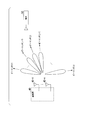
- FIG. 1 is a diagram showing an overall configuration of a wireless communication system 10 according to an embodiment of the present invention.
- the wireless communication system 10 includes an accommodation station 20, a base station 40, and a terminal 50.
- the accommodation station 20 and the base station 40 are connected by an optical fiber 30.
- the accommodation station 20 and the base station 40 perform optical fiber communication, and the base station 40 and the terminal 50 perform wireless communication.
- the accommodation station 20, the optical fiber 30, and the base station 40 constitute, for example, a RoF system.
- FIG. 2 is a diagram showing the basic principle of beamforming of the transmitting antenna according to the present embodiment.
- the accommodation station 20 includes a phase adjusting unit 21 and an optical combiner 22.
- the base station 40 includes an optical demultiplexer 41, n (n is an integer of 2 or more) O/E (optical/electrical) converters 42, and n antenna elements 43.
- 42 is referred to as an O/E converter 42-i.
- the wavelength lambda 11 phase adjusting unit 21 is phase adjusted, ..., wavelength-multiplexes the optical modulation signal of lambda 1n, and transmits to the base station 40 by one optical fiber 30. At this time, the distance information of the optical fiber 30 may not be known.
- optical modulation signals of wavelengths ⁇ 11 ,..., ⁇ 1n are transmitted through an optical fiber, different delay differences occur due to the influence of chromatic dispersion, and different phase rotations occur. Since the wavelengths ⁇ 11 ,..., ⁇ 1n are arranged at equal intervals with a sufficiently small wavelength interval, delay differences due to chromatic dispersion can also be made equal intervals. Furthermore, the amount of phase rotation of the optical modulation signals of the wavelengths ⁇ 11 ,..., ⁇ 1n as an RF signal is also equidistant.
- the modulated signal is output to the antenna element 43-i.
- the optical modulation signals of wavelengths ⁇ 11 ,..., ⁇ 1n are O/E converted by O/E converters 42-1,..., 42-n, respectively, and RF signals are output from antenna elements 43-1,..., 43-n. Is emitted as.
- FIG. 3 is a diagram showing a beam direction of a transmission RF signal emitted from the base station 40. It is assumed that the antenna elements 43-1,..., 43-n are arranged at equal intervals d. That is, the distance between the antenna element 43-i and the antenna element 43-(i+1) is d. Further, the transmission beam direction of each antenna element 43 is ⁇ , and the wavelength of the transmission RF signal is ⁇ RF1 . In this case, a transmission beam is formed in a direction that satisfies the following expression (1).
- ⁇ 1 is a constant whose specific value is unknown.
- Variables that define the transmit beam direction ⁇ is only the alpha 1, it is possible to change the transmission beam direction ⁇ by changing the value of alpha 1. Since the accommodation station 20 controls the value of ⁇ 1, the control of the base station 40 is basically not necessary for the control of the transmission beam direction. However, if the distance information of the optical fiber 30 is not known, the specific value of ⁇ 1 is not known, so the specific value of the transmission beam direction ⁇ is also unknown.
- the transmission beam direction formed by the base station 40 is unknown. Therefore, feedback of the terminal 50, which is a communication partner of the base station 40, is required to determine the transmission beam direction.
- the beam direction determining flow will be described in detail after the beam forming of the receiving antenna is described.
- FIG. 4 is a diagram showing the basic principle of beamforming of the receiving antenna in the wireless communication system 10 according to the present embodiment. In FIG. 4, only functional units related to reception are shown.
- the accommodation station 20 includes an optical demultiplexer 23 and a phase adjustment unit 24.
- the base station 40 includes n antenna elements 43-1,..., 43-n, n E/O (electrical/optical) converters 44, and an optical combiner 45.
- Equation (2) is established.
- the wavelength is multiplexed by the optical combiner 45 and transmitted to the accommodating station 20 through one optical fiber 30. At this time, the distance information of the optical fiber 30 may not be known.
- optical modulation signals of wavelengths ⁇ 21 ,..., ⁇ 2n are transmitted through an optical fiber, different delay differences occur due to the influence of chromatic dispersion, and different phase rotations occur. Since the wavelengths ⁇ 21 ,..., ⁇ 2n are arranged at equal intervals with a sufficiently small wavelength interval, the delay differences due to chromatic dispersion are also at equal intervals, and as the RF signal of the optical modulation signal of the wavelengths ⁇ 21 ,. The phase rotation amounts of are also equally spaced.
- the wavelength lambda 21, ..., lambda 2n optical modulation signal phase rotation amount beta 21 as RF signals, ..., respectively beta 2n is, ⁇ 21, ⁇ 21 - ⁇ 2 , ⁇ 21 -2 ⁇ 2, ..., ⁇ 21 ⁇ (n ⁇ 1) ⁇ 2 .
- Wavelength lambda 21 accommodating station 20 receives, ⁇ 22, ⁇ 23, ... , the phase of the RF signal of the modulated optical signal of lambda 2n is, ⁇ 21 + ⁇ 21, ⁇ 21 + ⁇ 21 + ⁇ 2 - ⁇ 2, ⁇ 21 + ⁇ 21 +2( ⁇ 2 ⁇ 2 ),..., ⁇ 21 + ⁇ 21 +(n ⁇ 1)( ⁇ 2 ⁇ 2 ).
- the phase adjustment unit 24 performs the phase adjustment of (i-1) ⁇ 2 as an RF signal on the optical modulation signal having the wavelength ⁇ 2i demultiplexed by the optical demultiplexer 23. Then, the phases of the optical modulation signals of the wavelengths ⁇ 21 , ⁇ 22 , ⁇ 23 ,..., ⁇ 2n as the RF signal are ⁇ 21 + ⁇ 21 , ⁇ 21 + ⁇ 21 + ⁇ 2 ⁇ 2 + ⁇ 2 , ⁇ 21 + ⁇ 21 +2. ( ⁇ 2 ⁇ 2 + ⁇ 2 ),..., ⁇ 21 + ⁇ 21 +(n ⁇ 1) ( ⁇ 2 ⁇ 2 + ⁇ 2 ).
- the accommodating station 20 may perform these phase adjustments not on the optical modulation signals of the wavelengths ⁇ 21 ,..., ⁇ 2n but on the electric signals after E/O conversion of these optical modulation signals.
- FIG. 5 is a diagram showing p (p is an integer of 2 or more) beacons B(1),..., B(p) transmitted from the base station 40.
- the accommodation station 20 generates p beacons B(1),..., B(p) as RF signals.
- the wavelength lambda 11 is phase adjusted by the phase adjusting unit 21, ..., and a wavelength-multiplexed optical modulation beacon B (j) of the lambda 1n, is transmitted by the optical fiber 30 to the base station 40.
- the optical demultiplexer 41 of the base station 40 demultiplexes the wavelength multiplexed optical signal transmitted through the optical fiber 30 into the optical modulation beacons B(j) having the wavelengths ⁇ 11 ,..., ⁇ 1n .
- the O/E converter 42-i converts the optical modulation beacon B(j) having the wavelength ⁇ 1i from the optical signal into the electric signal beacon B(j), and the antenna element 43-i converts the wavelength into the electric signal.
- the beacon B(j) It emits a light modulation beacon B(j) of ⁇ 1i .
- the beacon B(j) is radiated from the antenna elements 43-1,..., 43-n.
- the beacon B(j) is emitted in the direction ⁇ j that satisfies the following expression (3).
- beacons are provided in each of p different directions ⁇ 1 ,..., ⁇ p from the base station 40. B(1),..., B(p) can be transmitted.
- the beacon number information is an example of information that uniquely identifies the beacons B(1),..., B(p). Below, the beacon number information of beacon B (j) is set to j.
- the base station 40 uses the E/O converters 44-1,..., 44-n to convert the beacon number information fed back from the terminal 50 from an electric signal to an optical signal, and the optical combiner 45 directly combines the wavelengths with each other. It transmits to the accommodation station 20 via the fiber 30.
- the phase adjusting unit 24 of the accommodating station 20 obtains the reception power while adjusting the phase of the beacon number information received q times by using different values ⁇ 21 , .., ⁇ 2q as the value of ⁇ 2. ..
- the accommodating station 20 also determines the value of ⁇ 1 based on the received beacon number information, and determines the beam direction of the transmitting antenna. That is, central office 20, when the beacon ID information is j, to determine the value of alpha 1 to alpha 1j.
- FIG. 6 is a diagram showing a flow of beam direction determination in the wireless communication system 10.
- FIG. 6 shows the above operation in each of the accommodation station 20, the base station 40, and the terminal 50 on the same time axis.
- the accommodating station 20 generates optical modulation beacons B(1),..., B(p) whose phases have been adjusted by using ⁇ 11 ,..., ⁇ 1p respectively for ⁇ 1 and transmits them to the base station 40 (step S11). ..
- the base station 40 O/E-converts the received light-modulated beacons B(1),..., B(p) into an RF signal (step S12), and the beacon B(1),..., Converted into the RF signal.
- B(p) is transmitted at different timings (step S13).
- the terminal 50 transmits beacon number information specifying the selected beacon B(j) q times to the base station 40 (step S15).
- the base station 40 E/O-converts the received q pieces of beacon number information (step S16) and transmits them to the accommodation station 20 (step S17).
- the accommodation station 20 determines the reception beam direction (step S18). In addition, the accommodating station 20 determines the value of ⁇ 1 for ⁇ 1j used when transmitting the beacon B(j) indicated by the received beacon number information j. Thereby, the accommodation station 20 determines the transmission beam direction (step S19).
- the base station 40 only O/E-converts and E/O-converts the signals received from the accommodation station 20 and the terminal 50, and basically does not require any phase adjustment control.
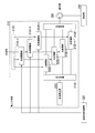
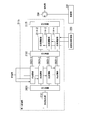
- FIG. 7 is a block diagram showing the configuration of the accommodation station 20, and only the functional blocks related to the present embodiment are extracted and shown.
- the accommodation station 20 includes a transmitter 210, a transmission phase controller 220, a receiver 230, a reception phase controller 240, and an optical circulator 250.
- the transmitter 210 generates a transmission light modulation signal having wavelengths ⁇ 11 ,..., ⁇ 1n .
- the transmitter 210 performs phase adjustment on the optical modulation signal obtained by modulating the light of each wavelength with the RF signal in order to adjust the phase of the transmission optical modulation signal.
- the transmission unit 210 the first transmission unit 211 shown in FIG. 8 described later can be used.
- the transmission unit 210 performs phase adjustment on the branched RF signal for use in modulation of light of each wavelength in order to adjust the phase of the transmission light modulation signal, and the phase-adjusted RF signal causes each of the wavelengths of each wavelength to be adjusted. Modulates light.
- the second transmission unit 212 shown in FIG. 9 described later can be used.
- the transmission phase control unit 220 instructs the transmission unit 210 about the magnitude of phase adjustment.
- the receiving unit 230 performs phase adjustment on the received optical modulation signals of wavelengths ⁇ 21 ,..., ⁇ 2n to obtain demodulated signals.
- the receiving section 230 performs phase adjustment on each of the demultiplexed optical modulation signals in order to adjust the phase of the received optical modulation signal.
- the receiving section 230 the first receiving section 231 shown in FIG. 10 described later can be used.
- the receiving unit 230 performs phase adjustment on the RF signal obtained by O/E converting each demultiplexed optical modulation signal in order to adjust the phase of the received optical modulation signal.
- the second receiving section 232 shown in FIG. 11 described later can be used.
- the reception phase control unit 240 instructs the reception unit 230 on the magnitude of the phase adjustment.
- the optical circulator 250 inputs the transmission light modulation signal output from the transmission unit 210 and outputs it to the optical fiber 30, and inputs the reception light modulation signal transmitted through the optical fiber 30 and outputs it to the reception unit 230.
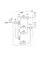
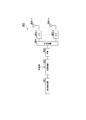
- FIG. 8 is a block diagram showing the configuration of the first transmission unit 211.
- the first transmitter 211 includes a multi-wavelength light source 2111, an optical modulator 2112, an optical demultiplexer 2113, phase adjusters 2114-2,..., 2114-n, and an optical combiner 2115.
- the multi-wavelength light source 2111 outputs light of wavelengths ⁇ 11 ,..., ⁇ 1n .
- the light modulator 2112 modulates the lights of the wavelengths ⁇ 11 ,..., ⁇ 1n output from the multi-wavelength light source 2111 by RF signals.
- the optical demultiplexer 2113 branches the optical modulation signals having the wavelengths ⁇ 11 ,..., ⁇ 1n .
- the phase adjusters 2114-2,..., 2114-n correspond to the phase adjuster 21 of FIG.
- the light combiner 2115 corresponds to the light combiner 22 in FIG.
- the optical combiner 2115 combines the optical modulation signal of ⁇ 11 output by the optical demultiplexer 2113 and the optical modulation signals of ⁇ 12 ,..., ⁇ 1n output by the phase adjusting units 2114-2,..., 2114-n, respectively. They are combined and output to the optical circulator 250.
- the optical circulator 250 outputs the combined optical modulation signal to the optical fiber 30.
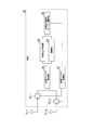
- FIG. 9 is a block diagram showing the configuration of the second transmission unit 212.
- the second transmission unit 212 includes a multi-wavelength light source 2121, an optical demultiplexer 2122, a branching unit 2123, phase adjustment units 2124-2,..., 2124-n, and optical modulation units 2125-1,..., 2125-. n and an optical combiner 2126.
- the multi-wavelength light source 2121 outputs light of wavelengths ⁇ 11 ,..., ⁇ 1n .
- the optical demultiplexer 2122 branches the optical modulation signals having the wavelengths ⁇ 11 ,..., ⁇ 1n .
- the branching unit 2123 branches the RF signal into n signals, and outputs the RF signals to the optical modulator 2125-1 and the phase adjusters 2124-2,..., 2124-n.
- the phase adjusters 2124-2,..., 2124-n correspond to the phase adjuster 21 of FIG.
- the optical modulator 2125-1 modulates the light of wavelength ⁇ 11 demultiplexed by the optical demultiplexer 2122 with an RF signal and outputs it to the optical combiner 2126.
- the light combiner 2126 corresponds to the light combiner 22 in FIG.
- the optical combiner 2126 combines the optical modulation signals of ⁇ 11 ,..., ⁇ 1n output from the optical modulators 2125-1,..., 2125-n, and outputs the combined signals to the optical circulator 250.
- the optical circulator 250 outputs the combined optical modulation signal to the optical fiber 30.
- FIG. 10 is a block diagram showing the configuration of the first reception unit 231.
- the first receiver 231 includes an optical demultiplexer 2311, phase adjusters 2312-2,..., 2312-n, an optical combiner 2313, an O/E converter 2314, a received power calculator 2315, and a demodulator. 2316.
- the optical demultiplexer 2311 receives the received optical modulation signal output from the base station 40 from the optical circulator 250, and branches it into optical modulation signals of wavelengths ⁇ 22 ,..., ⁇ 2n .
- the phase adjusting units 2312-2,..., 2312-n correspond to the phase adjusting unit 24 in FIG.
- the optical combiner 2313 outputs the optical modulation signal of the wavelength ⁇ 21 output from the optical demultiplexer 2311 and the optical modulation signals of the wavelengths ⁇ 22 ,..., ⁇ 2n output by the phase adjusting units 2312-2,..., 2312-n, respectively. And are combined and output to the O/E converter 2314.
- the O/E converter 2314 outputs the optical modulation signal combined by the optical combiner 2313 into an electric signal, and outputs the electric signal to the reception power calculation unit 2315 and the demodulation unit 2316.
- the reception power calculator 2315 calculates the reception power of the electric signal input from the O/E converter 2314, and outputs the calculation result to the reception phase controller 240.
- the demodulation unit 2316 demodulates the reception signal converted into the electric signal. When demodulation section 2316 obtains the beacon number information transmitted by terminal 50 by demodulation, demodulation section 2316 outputs the obtained beacon number information to transmission phase control section 220.
- FIG. 11 is a block diagram showing the configuration of the second receiving unit 232.
- the second receiving unit 232 includes an optical demultiplexer 2321, O/E converters 2322-1,..., 2322-n, phase adjusting units 2323-2,..., 2323-n, and a received power calculating unit 2324. , Demodulation section 2325.
- the optical demultiplexer 2321 receives the received optical modulation signal output from the base station 40 from the optical circulator 250 and branches it into optical modulation signals of wavelengths ⁇ 22 ,..., ⁇ 2n .
- the reception power calculation unit 2324 calculates reception power using the electric signal output by the O/E converter 2322-1 and the electric signals output by the phase adjustment units 2323-2,..., 2323-n, The calculation result is output to the reception phase control unit 240.
- the demodulation unit 2325 uses the electric signal output from the O/E converter 2322-1 and the electric signals output from each of the phase adjustment units 2323-2,..., 2323-n to transmit the signal transmitted from the terminal 50. Demodulate. When the demodulation unit 2325 obtains the beacon number information transmitted by the terminal 50 by demodulation, the demodulation unit 2325 outputs the obtained beacon number information to the transmission phase control unit 220.
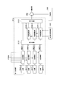
- FIG. 12 is a block diagram showing the configuration of the base station 40, and only the functional blocks related to this embodiment are extracted and shown.
- the base station 40 includes an optical demultiplexer 41, O/E converters 42-1,..., 42-n, antenna elements 43-1,..., 43-n, an E/O converter 44-1 and , 44-n, an optical combiner 45, an optical circulator 46, and electric circulators 47-1,..., 47-n.
- the optical combiner 45 outputs a received optical modulation signal obtained by combining the optical modulation signals of the wavelengths ⁇ 21 ,..., ⁇ 2n output from the E/O converters 44-1,..., 44-n, respectively.
- the optical circulator 46 inputs the transmission optical modulation signal transmitted through the optical fiber 30 and outputs it to the optical demultiplexer 41. Further, the optical circulator 46 inputs the received optical modulation signal combined by the optical combiner 45 and outputs it to the optical fiber 30.
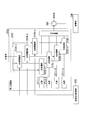
- FIG. 13 is a block diagram showing the configuration of the terminal 50, and only the functional blocks related to the present embodiment are extracted and shown.
- the terminal 50 includes antenna elements 51-1,..., 51-m (m is an integer of 1 or more), electric circulators 52-1,..., 52-m, a reception antenna control unit 53, and a reception power calculation unit 54.
- the antenna elements 51-1,..., 51-m output RF signals received wirelessly to the reception antenna control unit 53. Further, the antenna elements 51-1,..., 51-m radiate the RF signal output by the transmission antenna control unit 57.
- the reception antenna control unit 53 has a function of controlling the beam forming of the reception antenna of the terminal 50 and the like.
- the reception power calculation unit 54 calculates the reception power of the received beacon and outputs the calculation result to the maximum reception power beacon selection unit 56.
- the demodulation unit 55 demodulates the received signal.
- the demodulation unit 55 outputs beacon number information obtained from the information included in the beacon to the maximum received power beacon selection unit 56.
- the maximum received power beacon selection unit 56 acquires the beacon number information of the beacon with the maximum received power based on the received power calculated by the received power calculation unit 54, and outputs it to the transmission antenna control unit 57.
- the transmission antenna control unit 57 controls the RF signal in which the beacon number information is set to be transmitted p times from the antenna elements 51-1,..., 51-m. Further, the transmission antenna control unit 57 has a function of controlling the beam forming of the transmission antenna of the terminal 50.
- the first transmitting unit 211 shown in FIG. 8 and the first receiving unit 231 shown in FIG. 10 are used as the transmitting unit 210 and the receiving unit 230 of the accommodation station 20.
- the accommodating station 20 adjusts the phase of the optical modulation signal of each wavelength in order to adjust the phase of the transmission optical modulation signal and the reception optical modulation signal.
- the multi-wavelength light source 2111 of the accommodation station 20 generates optical signals of n different wavelengths ⁇ 11 ,..., ⁇ 1n .
- Optical signals of wavelengths ⁇ 11 ,..., ⁇ 1n are input to one optical modulator 2112.
- the optical modulator 2112 modulates the optical signal of the wavelengths ⁇ 11 ,..., ⁇ 1n input from the multi-wavelength light source 2111 using the input RF signal, and the optical modulation signal of the wavelengths ⁇ 11 ,..., ⁇ 1n. Is output.
- a signal obtained by modulating an optical signal with an RF signal becomes a DSB (double side band) signal.
- this DSB signal is transmitted through an optical fiber, it is affected by chromatic dispersion, a delay difference occurs between the lower sideband and the upper sideband, and fading occurs. Therefore, the length of the optical fiber that can be transmitted is limited. The higher the frequency of the RF signal, the wider the spacing between the sidebands, and the more pronounced the effect of fading.
- the optical modulation unit 2112 may have a function of performing the fading countermeasure due to the wavelength dispersion, such as converting the optical modulation signal into an SSB (single side band) signal or a two-tone signal. ..
- the optical demultiplexer 2113 fixedly branches the optical modulation signals having the wavelengths ⁇ 11 ,..., ⁇ 1n .
- the optical modulation signals of the wavelength ⁇ 11 are sent to the optical combiner 2115 as they are, and the optical modulation signals of the wavelengths ⁇ 12 ,..., ⁇ 1n are sent to the phase adjusting units 2114-2,..., 2114-n, respectively.
- control of the optical demultiplexer 2113 is not necessary.
- the transmission phase controller 220 inputs the value of ⁇ 1 to the n ⁇ 1 phase adjusters 2114-2,..., 2114-n.
- the amount of phase adjustment as an RF signal for the optical modulation signals of wavelengths ⁇ 11 , ⁇ 12 , ⁇ 13 ,..., ⁇ 1n is 0, ⁇ 1 , 2 ⁇ 1 ,..., (n-1) ⁇ 1 , respectively
- the optical combiner 2115 combines the optical modulation signal of the wavelength ⁇ 11 and the phase-adjusted optical modulation signal of the wavelengths ⁇ 12 ,..., ⁇ 1n .
- the combined optical modulation signal is sent to the base station 40 via the optical circulator 250 and the optical fiber 30. At this time, the distance information of the optical fiber 30 may not be known.
- optical modulation signals of wavelengths ⁇ 11 ,..., ⁇ 1n are transmitted through an optical fiber, different delay differences occur due to the influence of chromatic dispersion, and different phase rotations occur. Since the wavelengths ⁇ 11 ,..., ⁇ 1n are arranged at equal intervals with a sufficiently small wavelength interval, the delay differences due to chromatic dispersion can also be made equal intervals, and the optical modulation signals of the wavelengths ⁇ 11 ,. The amount of phase rotation as an RF signal is also equidistant.
- the wavelength lambda 11, ..., the phase rotation amount beta 11 as an RF signal of the optical modulation signal of lambda 1n, ..., respectively ⁇ 1n, ⁇ 11, ⁇ 11 - ⁇ 1, ⁇ 11 -2 ⁇ 1, ..., ⁇ 11 - (n-1) ⁇ 1 next, ⁇ 1i ⁇ 11 - ( i-1) can be [Delta] [beta] 1 and expression. Since the wavelengths ⁇ 11 ,..., ⁇ 1n are fixed, the amount of phase rotation ⁇ 11 ,..., ⁇ 1n as an RF signal is a constant. However, if the distance information of the optical fiber 30 is not known, the values of the phase rotation amounts ⁇ 11 ,..., ⁇ 1n as RF signals cannot be specifically obtained.
- optical modulation signals of wavelengths ⁇ 11 ,..., ⁇ 1n transmitted from the accommodation station 20 to the base station 40 are fixedly branched by the optical demultiplexer 41 via the optical circulator 46, and the antenna elements 43-1 are respectively provided. ,..., 43-n. At this time, since the optical branch is fixed, control of the optical demultiplexer 41 is not necessary.
- the wavelength of the transmission RF signal is ⁇ RF1
- the transmission beam direction ⁇ is defined as shown in FIG.
- a transmission beam is formed in a direction that satisfies Expression (1).
- the wavelength ⁇ RF1 of the transmission RF signal and the antenna element spacing d are known constants. Since the wavelengths ⁇ 11 ,..., ⁇ 1n are fixed, ⁇ 1 is also a constant, but if the distance information of the optical fiber 30 is unknown, the value of the phase rotation amount ⁇ 11 ,. Cannot be specifically obtained, and also a specific value of ⁇ 1 cannot be obtained. Therefore, only ⁇ 1 defines the transmission beam direction ⁇ . This means that a transmission beam can be formed in a certain direction ⁇ by changing ⁇ 1 , but the specific direction is unknown. However, since only the accommodation station 20 controls ⁇ 1 , basically no control of the base station 40 for forming the transmission beam is necessary.
- the transmission beam direction ⁇ formed by the base station 40 is unknown. Therefore, feedback of the terminal 50, which is a communication partner of the base station 40, is required to determine the transmission beam direction.
- the transmission beam direction determination flow will be described in detail after the beam forming of the receiving antenna is described.
- the signal from the terminal 50 arrives from the direction ⁇ as shown in FIG.
- the phase of the RF signal received by the antenna element 43-i is ⁇ 2i
- the above equation (2) holds when the wavelength of the received RF signal is ⁇ RF2
- ⁇ 2i ⁇ 21 +(i ⁇ 1) It can be expressed as ⁇ 2 . That is, the E/O converter 44-i corresponding to the antenna element 43-i modulates the optical signal of wavelength ⁇ 2i with the received RF signal of phase ⁇ 2i and outputs the optical modulation signal of wavelength ⁇ 2i .
- the optical combiner 45 combines the optical modulation signals of the wavelengths ⁇ 21 ,..., ⁇ 2n .
- the combined optical modulation signal is sent to the accommodation station 20 via the optical circulator 46 and the optical fiber 30. At this time, the distance information of the optical fiber 30 may not be known.
- optical modulation signals of wavelengths ⁇ 21 ,..., ⁇ 2n are transmitted through an optical fiber, different delay differences occur due to the influence of chromatic dispersion, and different phase rotations occur. Since the wavelengths ⁇ 21 ,..., ⁇ 2n are arranged at equal intervals with a sufficiently small wavelength interval, the delay differences due to chromatic dispersion can be made equal intervals, and the optical modulation signals of the wavelengths ⁇ 21 ,. The amount of phase rotation as an RF signal is also equidistant.
- Wavelength lambda 21 accommodating station 20 receives, ⁇ 22, ⁇ 23, ... , the phase of the RF signal of the modulated optical signal of lambda 2n is, ⁇ 21 + ⁇ 21, ⁇ 21 + ⁇ 21 + ⁇ 2 - ⁇ 2, ⁇ 21 + ⁇ 21 +2( ⁇ 2 ⁇ 2 ),..., ⁇ 21 + ⁇ 21 +(n ⁇ 1)( ⁇ 2 ⁇ 2 ).
- the optical modulation signals of wavelengths ⁇ 21 ,..., ⁇ 2n transmitted from the base station 40 through the optical fiber are fixedly branched by the optical demultiplexer 2311 of the first receiving unit 231 via the optical circulator 250 of the accommodation station 20. ..
- the optical modulation signal of the wavelength ⁇ 21 is sent to the optical combiner 2313 as it is, and the optical modulation signals of the wavelengths ⁇ 22 ,..., ⁇ 2n are respectively sent to the phase adjusting units 2312-2,.
- control of the optical demultiplexer 2311 is not necessary.
- the reception phase control unit 240 inputs the value of ⁇ 2 to the n ⁇ 1 phase adjustment units 2312-2,..., 2312-n.
- the amount of phase adjustment as an RF signal for the optical modulation signals of wavelengths ⁇ 21 , ⁇ 22 , ⁇ 23 ,..., ⁇ 2n is 0, ⁇ 2 , 2 ⁇ 2 ,..., (n-1) ⁇ 2 , respectively.
- the phases of the optical modulation signals of wavelengths ⁇ 21 , ⁇ 22 , ⁇ 23 ,..., ⁇ 2n as RF signals are ⁇ 21 + ⁇ 21 , ⁇ 21 + ⁇ 21 + ⁇ 2 ⁇ 2 + ⁇ 2 , ⁇ 21 + ⁇ 21 +2 ( ⁇ 2 ⁇ 2 + ⁇ 2 ),..., ⁇ 21 + ⁇ 21 +(n ⁇ 1) ( ⁇ 2 ⁇ 2 + ⁇ 2 ).
- ⁇ 2 ⁇ 2 - ⁇ 2
- wavelength lambda 21, ... the phase of the RF signal of the modulated optical signal of lambda 2n is in phase with ⁇ 21 + ⁇ 21, the beam of the receiving antenna in the direction ⁇ It is formed.
- the variable defining the reception beam direction ⁇ is only the alpha 2, it is possible to change the reception beam direction ⁇ by changing the alpha 2 values. Since the accommodation station 20 controls ⁇ 2 , the control of the base station 40 is basically not necessary for controlling the reception beam direction.
- the beam direction determination flow of the reception antenna/transmission antenna is the same as that in FIG. 6 described above.
- the accommodating station 20 generates p beacons B(1),..., B(p) as RF signals, and inputs them to the optical modulator 2112 in order.
- the 1n light modulation beacon B(j) is output.
- the optical demultiplexer 2113 branches the optical modulation beacon B(j) having the wavelengths ⁇ 11 ,..., ⁇ 1n .
- the optical modulation beacon B(j) with the wavelength ⁇ 11 is output to the optical combiner 2115 as it is.
- Phase adjusting unit 2114-2, ..., respectively 2114-n, as ⁇ 1 ⁇ 1j under the control of the transmission phase control unit 220, the wavelength lambda 12, ..., with respect to lambda 1n of the optical modulation beacon B (j) Adjust the phase. Therefore, the transmission phase control unit 220 causes the phase adjusting units 2114-2,..., 2114-n to set ⁇ 1 values corresponding to the p optical modulation beacons B(1),..., B(p), respectively.
- the different values ⁇ 11 ,..., ⁇ 1p are designated.
- the optical combiner 2115 combines the phase-adjusted optical modulation beacons B(j) of the wavelengths ⁇ 11 ,..., ⁇ 1n .
- the combined optical modulation beacon B(j) is transmitted through an optical fiber, is O/E converted in the base station 40, and is emitted from the antenna elements 43-1,..., 43-n as a beacon B(j). ..
- the beacon B(j) is radiated in the direction ⁇ j that satisfies the above equation (3).
- the wireless communication system 10 performs the above-described operation on the p beacons B(1),..., B(p), so that as shown in FIG. 5, p different directions ⁇ 1 from the base station 40, , ⁇ p can be transmitted to beacons B(1),..., B(p), respectively (steps S11 to S13 in FIG. 6).
- the antenna elements 51-1,..., 51-m of the terminal 50 receive p beacons B(1),..., B(p) from the base station 40.
- the reception antenna control unit 53 outputs the p beacons B(1),..., B(p) received by the antenna elements 51-1,..., 51-m to the reception power calculation unit 54 and the demodulation unit 55. ..
- the reception power calculation unit 54 calculates the reception power of each of the p received beacons B(1),..., B(p), and outputs the result.
- the demodulation unit 55 demodulates each of the received p beacons B(1),..., B(p) and outputs a beacon number.
- the maximum reception power beacon selection unit 56 selects the beacon number having the maximum reception power based on the reception power and beacon number of the beacon input from the reception power calculation unit 54 and the demodulation unit 55, and the beacon number information thereof. Is output (step S14 in FIG. 6).
- the transmission antenna control unit 57 controls so that the beacon number information output by the maximum reception power beacon selection unit 56 is transmitted from the antenna elements 51-1,..., 51-m to the base station 40.
- the terminal 50 transmits this beacon number information q times (step S15 in FIG. 6).
- Step S16 The optical combiner 45 combines the optical modulation beacon number information of the wavelengths ⁇ 21 ,..., ⁇ 2n obtained by this E/O conversion, and transmits it to the accommodation station 20. Since the base station 40 transmits the beacon number information q times from the terminal 50, the base station 40 transmits the light modulation beacon number information q times to the accommodation station 20 at different timings (step S17 in FIG. 6 ).
- the optical demultiplexer 2311 of the accommodation station 20 branches the optical modulation beacon number information transmitted from the base station 40 into the optical modulation beacon number information of the wavelengths ⁇ 21 ,..., ⁇ 2n .
- Light modulation beacon number information of a wavelength lambda 21 is directly sent to a combiner 2313, a wavelength lambda 22, ..., lambda 2n optical modulation beacon ID information each phase adjusting unit 2312-2, ..., the phase adjustment in the 2312-n Done.
- the phase adjusting units 2312-2,..., 2312-n under the control of the reception phase control unit 240, have different ⁇ 2 values ⁇ 21 , ⁇ 2 for the optical modulation beacon number information received q times.
- the reception phase control unit 240 sequentially changes the ⁇ 2 value to ⁇ 21 ,..., ⁇ 2q each time the light modulation beacon number information is received, and instructs the phase adjustment units 2312-2,..., 2312-n. ..
- the O/E converter 2314 obtains beacon number information by O/E converting the combined light modulation beacon number information.
- the O/E converter 2314 outputs the beacon number information to the reception power calculation unit 2315 and the demodulation unit 2316.
- the reception power calculation unit 2315 receives q pieces of beacon number information for which different phase adjustments have been performed, calculates the reception power thereof, and notifies the reception phase control unit 240.
- the reception phase control unit 240 determines the value of ⁇ 2 when the reception power becomes maximum based on the notified reception power.
- the central office 20 a q-number of beacon number information received while scanning the value of alpha 2, is determined by selecting the values of the received power becomes maximum alpha 2. Thereby, the beam direction of the receiving antenna is determined (step S18 in FIG. 6).
- the reception phase control unit 240 controls the first reception unit 231 to use the determined value of ⁇ 2 when receiving a signal from the terminal 50.
- Demodulation section 2316 demodulates the received beacon number information and outputs it to transmission phase control section 220.
- the transmission phase controller 220 determines the value of ⁇ 1 based on the beacon number information. As a result, the beam direction of the transmitting antenna is determined (step S19 in FIG. 6).
- the transmission phase controller 220 controls the first transmitter 211 to use the determined value of ⁇ 1 when transmitting a signal to the terminal 50.
- the base station 40 only needs to perform O/E conversion and E/O conversion on the signals received from the accommodation station 20 and the terminal 50, and does not need control for controlling the beam direction.
- the second transmitting unit 212 shown in FIG. 9 and the second receiving unit 232 shown in FIG. 11 are used as the transmitting unit 210 and the receiving unit 230 of the accommodation station 20.
- the accommodating station 20 adjusts the phase of the RF signal in order to adjust the phase of the transmission light modulation signal and the reception light modulation signal.
- the multi-wavelength light source 2121 of the accommodation station 20 generates optical signals of n different wavelengths ⁇ 11 ,..., ⁇ 1n .
- the optical demultiplexer 2122 branches the optical signals of the wavelengths ⁇ 11 ,..., ⁇ 1n and inputs them into the optical modulators 2125-1,..., 2125-n, respectively.
- the transmission phase controller 220 inputs the value of ⁇ 1 to the n ⁇ 1 phase adjusters 2124-2,..., 2124-n.
- the branching unit 2123 branches the RF signal into n signals, and outputs the RF signals to the optical modulator 2125-1 and the phase adjusters 2124-2,..., 2124-n.
- the optical modulator 2125-1 modulates the optical signal of wavelength ⁇ 11 with the RF signal and outputs the optical modulation signal of wavelength ⁇ 11 .
- the optical modulators 2125-1,..., 2125-n may have a function of taking measures against fading due to wavelength dispersion.
- the optical combiner 2115 combines the optical modulation signals having the wavelengths ⁇ 11 ,..., ⁇ 1n .
- the combined optical modulation signal is sent to the base station 40 via the optical circulator 250 and the optical fiber 30. At this time, the distance information of the optical fiber 30 may not be known.
- the optical modulation signals having the wavelengths ⁇ 11 ,..., ⁇ 1n are transmitted through the optical fiber, different delay differences occur due to the influence of chromatic dispersion, and different phase rotations occur. Since the wavelengths ⁇ 11 ,..., ⁇ 1n are arranged at equal intervals with a sufficiently small wavelength interval, the delay differences due to chromatic dispersion can also be made equal intervals, and the optical modulation signals of the wavelengths ⁇ 11 ,. The amount of phase rotation as an RF signal is also equidistant.
- the wavelength lambda 11, ..., the phase rotation amount beta 11 as an RF signal of the optical modulation signal of lambda 1n, ..., respectively ⁇ 1n, ⁇ 11, ⁇ 11 - ⁇ 1, ⁇ 11 -2 ⁇ 1, ..., ⁇ 11 - (n-1) ⁇ 1 next, ⁇ 1i ⁇ 11 - ( i-1) can be [Delta] [beta] 1 and expression. Since the wavelengths ⁇ 11 ,..., ⁇ 1n are fixed, the amount of phase rotation ⁇ 11 ,..., ⁇ 1n as an RF signal is a constant. However, if the distance information of the optical fiber is not known, the values of the phase rotation amounts ⁇ 11 ,..., ⁇ 1n as RF signals cannot be specifically obtained.
- the operations of the base station 40 and the terminal 50 are similar to those of the operation example 1. That is, the optical modulation signals of wavelengths ⁇ 11 ,..., ⁇ 1n transmitted from the accommodation station 20 to the base station 40 are fixedly branched by the optical demultiplexer 41 via the optical circulator 46. Since the optical branch is fixed, it is not necessary to control the optical demultiplexer 41. , 42-n respectively convert the optical modulation signals of wavelengths ⁇ 11 ,..., ⁇ 1n branched by the optical demultiplexer 41 into RF signals.
- a phase rotation of ⁇ 1 is applied.
- the phase difference between adjacent antenna elements is constant at ⁇ 1 ⁇ 1 .
- the wavelength of the transmission RF signal is ⁇ RF1
- the transmission beam direction ⁇ is defined as shown in FIG.
- a transmission beam is formed in a direction that satisfies Expression (1).
- the wavelength ⁇ RF1 of the transmission RF signal and the antenna element spacing d are known constants.
- Wavelength lambda 11, ..., since lambda 1n is fixed, [Delta] [beta] 1 is also a constant, if the distance information of the optical fiber 30 is not known, the phase rotation amount beta 11 as RF signals, ..., the beta 1n
- the value cannot be specifically determined, and ⁇ 1 its specific value cannot be determined. Therefore, only ⁇ 1 defines the transmission beam direction ⁇ . This means that it is possible to form the transmit beam in the direction ⁇ , which is a change of ⁇ 1 , but the specific direction is unknown.
- base station control for forming a transmission beam is not necessary at all.
- the transmission beam direction ⁇ formed by the base station 40 is not known. Therefore, feedback of the terminal 50, which is a communication partner of the base station 40, is required to determine the transmission beam direction.
- the transmission beam direction determination flow will be described in detail after the beam forming of the receiving antenna is described.
- the signal from the terminal 50 arrives at the base station 40 from the direction ⁇ as shown in FIG.
- the phase of the RF signal received by the antenna element 43-i is ⁇ 2i
- the E/O converter 44-i corresponding to the antenna element 43-i modulates the optical signal of wavelength ⁇ 2i with the received RF signal of phase ⁇ 2i and outputs the optical modulation signal of wavelength ⁇ 2i .
- the optical combiner 45 combines the optical modulation signals of the wavelengths ⁇ 21 ,..., ⁇ 2n .
- the combined optical modulation signal is sent to the accommodation station 20 via the optical circulator 46 and the optical fiber 30. At this time, the distance information of the optical fiber 30 may not be known.
- the wavelength lambda 21, ..., lambda when the optical fiber transmits an optical modulation signal of 2n different delay difference occurs due to the influence of chromatic dispersion, it undergoes a different phase rotation. Since the wavelengths ⁇ 21 ,..., ⁇ 2n are arranged at equal intervals with a sufficiently small wavelength interval, the delay differences due to chromatic dispersion can be made equal intervals, and the optical modulation signals of the wavelengths ⁇ 21 ,. The amount of phase rotation as an RF signal is also equidistant.
- the phases of the optical modulation signals of the wavelengths ⁇ 21 , ⁇ 22 , ⁇ 23 ,..., ⁇ 2n received by the accommodation station 20 as the RF signal are ⁇ 21 + ⁇ 21 , ⁇ 21 + ⁇ 21. + ⁇ 2 ⁇ 2 , ⁇ 21 + ⁇ 21 +2( ⁇ 2 ⁇ 2 ),..., ⁇ 21 + ⁇ 21 +(n ⁇ 1)( ⁇ 2 ⁇ 2 ).
- the optical modulation signals of wavelengths ⁇ 21 ,..., ⁇ 2n transmitted from the base station 40 through the optical fiber are fixedly branched by the optical demultiplexer 2321 of the second receiver 232 via the optical circulator 250 of the accommodation station 20. ..
- the O/E converters 2322-1,..., 2322-n respectively perform O/E conversion of the optical modulation signals of the wavelengths ⁇ 21 ,..., ⁇ 2n to convert the received signals (1),..., The received signal (n). obtain.
- the received signal (2),..., The received signal (n) are input to the phase adjusting units 2323-2,.
- the reception phase control unit 240 inputs the value of ⁇ 2 to the n ⁇ 1 phase adjustment units 2323-2,..., 2323-n.
- the phases of the reception signal (1), the reception signal (2), the reception signal (3),..., The reception signal (n) as RF signals are ⁇ 21 + ⁇ 21 and ⁇ 21 + ⁇ , respectively.
- ⁇ 2 ⁇ 2 ⁇ 2
- the phases of the received signal (1), the received signal (2), the received signal (3),..., The received signal (n) as RF signals are ⁇ 21 + ⁇ .
- the beams are in phase and a beam of the receiving antenna is formed in the direction ⁇ .
- the variable defining the reception beam direction ⁇ is only the alpha 2, it is possible to change the reception beam direction ⁇ by changing the alpha 2 values. Since the accommodation station 20 controls ⁇ 2 , the control of the base station 40 is basically not necessary for controlling the reception beam direction.
- the beam direction determination flow of the reception antenna/transmission antenna is the same as that in FIG. 6 described above.
- the accommodating station 20 generates p beacons B(1),..., B(p) as RF signals, and the branching unit 2123 causes the optical modulating unit 2125-1 and the phase adjusting units 2124-2,..., 2124-n. Enter in order.
- the transmission phase control unit 220 differs from the phase adjustment units 2124-2,..., 2124-n as the value of ⁇ 1 corresponding to each of the p beacons B(1),..., B(p).
- the values ⁇ 11 ,..., ⁇ 1p are designated.
- the optical modulator 2125-1 modulates the optical signal of wavelength ⁇ 1 using the beacon B(j) and outputs the optical modulation beacon B(j) of wavelength ⁇ 11 .
- the optical modulation beacon B(j) is output.
- the optical combiner 2126 combines the phase-adjusted optical modulation beacons B(j) of the wavelengths ⁇ 11 ,..., ⁇ 1n .
- the combined optical modulation beacon B(j) is transmitted through an optical fiber, is O/E converted in the base station 40, and is emitted from the antenna elements 43-1,..., 43-n as a beacon B(j). ..
- the beacon B(j) is radiated in the direction ⁇ j that satisfies the above equation (3).
- the wireless communication system 10 performs the above operation for the p beacons B(1),..., B(p), so that the base station 40 differs from the base station 40 as shown in FIG.
- the beacons B(1),..., B(p) can be transmitted in p directions ⁇ 1 ,..., ⁇ p , respectively (steps S11 to S13 in FIG. 6).
- the terminal 50 operates similarly to the operation example 1. That is, the reception antenna control unit 53 of the terminal 50 demodulates the p beacons B(1),..., B(p) received by the antenna elements 51-1,..., 51-m to the reception power calculation unit 54. It is output to the unit 55.
- the reception power calculation unit 54 calculates the reception power of each of the p received beacons B(1),..., B(p), and outputs the result.
- the demodulation unit 55 demodulates each of the received p beacons B(1),..., B(p) and outputs a beacon number.
- the maximum reception power beacon selection unit 56 selects the beacon number having the maximum reception power based on the reception power and beacon number of the beacon input from the reception power calculation unit 54 and the demodulation unit 55, and the beacon number information thereof.
- the transmission antenna control unit 57 controls so that the beacon number information output by the maximum reception power beacon selection unit 56 is transmitted from the antenna elements 51-1,..., 51-m to the base station 40.
- the terminal 50 transmits this beacon number information q times (step S15 in FIG. 6).
- the base station 40 performs E/O conversion on the beacon number information received from the terminal 50, and transmits the optical modulation beacon number information of the wavelengths ⁇ 21 ,..., ⁇ 2n to the accommodation station 20 (FIG. 6 step S16). Since the base station 40 transmits the beacon number information q times from the terminal 50, the base station 40 transmits the optical modulation beacon number information q times to the accommodation station 20 (step S17 in FIG. 6 ).
- the optical demultiplexer 2321 of the accommodation station 20 branches the optical modulation beacon number information transmitted from the base station 40 into the optical modulation beacon number information of the wavelengths ⁇ 21 ,..., ⁇ 2n . , 2322-n O/E convert the optical modulation beacon number information of the wavelengths ⁇ 21 ,..., ⁇ 2n , and receive beacon number information (1),..., (n). To get The received beacon number information (2),..., (n) is output to the phase adjusting units 2323-2,..., 2323-n, respectively.
- the phase adjustment units 2323-2,..., 2323-n perform phase adjustment on the received beacon number information (2),..., (n), respectively.
- the phase adjustment units 2323-2,..., 2323-n under the control of the reception phase control unit 240, have different ⁇ 2 values ⁇ 21 ,...
- ⁇ 2q adjusts the phase. Therefore, the reception phase control unit 240 sequentially changes the ⁇ 2 value to ⁇ 21 ,..., ⁇ 2q each time the light modulation beacon number information is received, and instructs the phase adjustment units 2323-2,... ..
- the received beacon number information (1) output by the O/E converter 2322-1 and the received beacon number information (2),... (N) is combined and output to the reception power calculation unit 2324 and the demodulation unit 2325.
- the reception power calculation unit 2324 receives q pieces of beacon number information for which different phase adjustments have been performed, calculates the reception power thereof, and notifies the reception phase control unit 240.
- the reception phase control unit 240 determines the value of ⁇ 2 when the reception power becomes maximum based on the notified reception power.
- the central office 20 a q-number of beacon number information received while scanning the value of alpha 2, is determined by selecting the values of the received power becomes maximum alpha 2.
- the beam direction of the receiving antenna is determined (step S18 in FIG. 6).
- the reception phase control unit 240 controls the second reception unit 232 to use the determined value of ⁇ 2 when receiving a signal from the terminal 50.
- the demodulation unit 2325 demodulates the received beacon number information and outputs it to the transmission phase control unit 220.
- the transmission phase controller 220 determines the value of ⁇ 1 based on the beacon number information. As a result, the beam direction of the transmitting antenna is determined (step S19 in FIG. 6).
- the transmission phase controller 220 controls the second transmitter 212 to use the determined value of ⁇ 1 when transmitting a signal to the terminal 50.
- the base station 40 only needs to perform O/E conversion and E/O conversion on the signals received from the accommodation station 20 and the terminal 50, and does not need control for controlling the beam direction.
- the first transmitting unit and the second receiving unit are used (Operation example 3)
- the first transmitter 211 shown in FIG. 8 and the second receiver 232 shown in FIG. 11 are used as the transmitter 210 and the receiver 230 of the accommodation station 20.
- the accommodating station 20 performs phase adjustment on the optical modulation signal in order to adjust the phase of the transmission light modulation signal, and performs phase adjustment on the RF signal in order to adjust the phase of the reception light modulation signal. That is, in the beam forming of the transmitting antenna, the wireless communication system 10 performs the same operation as in the operation example 1, and in the beam forming of the receiving antenna, the wireless communication system 10 performs the same operation as in the operation example 2.
- the second transmitting unit 212 shown in FIG. 9 and the first receiving unit 231 shown in FIG. 10 are used as the transmitting unit 210 and the receiving unit 230 of the accommodation station 20.
- the accommodating station 20 performs phase adjustment on the RF signal in order to adjust the phase of the transmission light modulation signal, and performs phase adjustment on the light modulation signal in order to adjust the phase of the reception light modulation signal. That is, in the beamforming of the transmitting antenna, the wireless communication system 10 performs the same operation as in the operation example 2, and in the beamforming of the receiving antenna, the wireless communication system 10 performs the same operation as in the operation example 1.
- FIG. 14 is a diagram showing the configuration of the first transmission unit 211a.
- the first transmitting unit 211a shown in FIG. 14 differs from the first transmitting unit 211 shown in FIG. 8 in that instead of the multi-wavelength light source 2111, n light sources 2611-1,... Is the point to be equipped with.
- the light combiner 2612 combines the lights of the wavelengths ⁇ 11 ,..., ⁇ 1n output from the light sources 2611-1,..., 2611-n and outputs the combined light to the light modulator 2112.
- FIG. 15 is a diagram showing the configuration of the first transmission unit 211b.
- the first transmitting unit 211b shown in FIG. 15 is different from the first transmitting unit 211 shown in FIG. 8 in that it replaces the optical modulator 2112 with an optical demultiplexer 2621 and optical modulators 2622-1,..., 2622. -N is provided.
- FIG. 16 is a diagram showing the configuration of the first transmission unit 211c.
- the first transmitting unit 211c shown in FIG. 16 is different from the first transmitting unit 211b shown in FIG. 15 in that the light sources 2611-1,... The point is to prepare.
- FIG. 17 is a diagram showing the configuration of the first transmission unit 211d.
- the same parts as those of the first transmitter 211 shown in FIG. The difference between the first transmission unit 211d shown in FIG. 17 and the first transmission unit 211 shown in FIG. 8 is that instead of the multi-wavelength light source 2111, the optical modulation unit 2112 and the optical demultiplexer 2113, n direct light modulation units are used. .., 2631-n.
- the optical combiner 2115 combines the optical modulation signal of ⁇ 11 output from the optical direct modulation unit 2631-1 and the optical modulation signals of ⁇ 12 to ⁇ 1n output from each of the phase adjusting units 2114-2,..., 2114-n. They are combined and output to the optical circulator 250.
- each of the second transmitters 212a and 212b which is a modification of the second transmitter 212 used as the transmitter 210 of the accommodation station 20, will be described with reference to FIGS. 18 and 19 below.
- FIG. 18 is a diagram showing the configuration of the second transmission unit 212a.
- the second transmitting section 212a shown in FIG. 18 is different from the second transmitting section 212 shown in FIG. 9 in that it replaces the multi-wavelength light source 2121 and the optical demultiplexer 2122 with n light sources 2711-1,. -N is provided.
- the light modulators 2125-i receive light of wavelengths ⁇ 11 ,..., ⁇ 1n from the light source 2711-i.
- FIG. 19 is a diagram showing the configuration of the second transmission unit 212b.
- the second transmitting section 212b shown in FIG. 19 is different from the second transmitting section 212 shown in FIG. 9 in that it is replaced with a multi-wavelength light source 2121, an optical demultiplexer 2122, and optical modulating sections 2125-1,..., 2125-n. , 2721-n.
- the optical direct modulator 2721-1 outputs an optical modulation signal obtained by modulating the light of wavelength ⁇ 1i with the RF signal to the optical combiner 2126.
- the optical combiner 2126 combines the optical modulation signals of ⁇ 11 ,..., ⁇ 1n output from the optical direct modulators 2721-1,..., 2721-n, and outputs the combined signals to the optical circulator 250.
- the chromatic dispersion of the optical fiber between the accommodating station and the base station is distributed to each of the n antenna elements arranged at equal intervals in the base station.
- the n wavelengths set at equal intervals within a range that can be regarded as constant are fixedly allocated.
- the accommodating station adjusts the phase of the optical signal of each wavelength or each modulated signal for modulating the optical signal of each wavelength so that the phase shift amounts in the RF signal are evenly spaced, thereby transmitting and receiving beam directions. To control.
- the accommodating station transmits the beacon signal from the base station multiple times while changing the transmission phase shift interval ⁇ 1 , and the terminal transmits the information of the beacon signal having the maximum received power multiple times.
- the base station receives the information of the beacon signal from the terminal, and the accommodating station changes the reception phase shift interval ⁇ 2 for the information of each received beacon signal to maximize the reception power. Determine the phase shift interval ⁇ 2 .
- the accommodation station determines the transmission phase shift interval ⁇ 1 based on the information of the beacon signal received from the terminal. According to the present embodiment, even if the information on the distance between the accommodation station and the base station is unknown, a wavelength forming efficiency is high and a beamforming type RoF system that does not require base station control is realized at low cost. can do.
- the wireless communication system includes the accommodating station apparatus, the base station apparatus connected to the accommodating station apparatus by the optical transmission line, and having n (n is an integer of 2 or more) antenna elements.
- a terminal that wirelessly communicates with the base station device is the accommodation station 20
- the base station device is the base station 40
- the terminal is the terminal 50
- the optical transmission line is the optical fiber 30.
- the accommodating station device has a transmission unit, a transmission phase control unit, a reception unit, a reception phase control unit, a transmission phase adjustment amount determination unit, and a reception phase adjustment amount determination unit.
- the transmitting unit performs phase adjustment by performing a first phase adjustment amount phase adjustment corresponding to each of the n first wavelengths on the optical modulation transmission signal obtained by modulating each of the n different first wavelength lights by the transmission signal.
- a combined optical modulation transmission signal obtained by combining the optical modulation transmission signals of the n first wavelengths is output to the optical transmission line.
- the transmission phase control unit controls the transmission unit to perform phase adjustment of a different first phase adjustment amount for each p beacon signals. Control.
- the receiver demultiplexes the composite optical modulation reception signal transmitted through the optical transmission line into n different optical modulation reception signals of the second wavelength, and the phase of the second phase adjustment amount corresponding to each of the n second wavelengths. Convert to adjusted electrical signal.
- the reception phase control unit is q (q is an integer of 2 or more) combined light indicating identification information (for example, beacon number information) of the beacon signal selected based on the reception power at the terminal among the p beacon signals.
- the receiving unit is controlled so as to perform the phase adjustment of the different second phase adjustment amount for each of q combined optical modulation reception signals.
- the transmission phase adjustment amount determination unit controls the transmission unit to perform the phase adjustment of the first phase adjustment amount used for the beacon signal of the identification information indicated by the combined light modulation reception signal.
- the reception phase adjustment amount determination unit adjusts the phase of the second phase adjustment amount used for the combined optical modulation reception signal selected based on the reception power of each of the electric signals converted from the q combined optical modulation reception signals. Control the receiver to do so.
- the transmission phase adjustment amount determination unit is the transmission phase control unit 220
- the reception phase adjustment amount determination unit is the reception phase control unit 240.
- the base station device includes a base station optical demultiplexing unit, a photoelectric conversion unit, an electro-optical conversion unit, and a base station optical combining unit.
- the base station optical demultiplexing unit is the optical demultiplexer 41
- the photoelectric conversion units are O/E converters 42-1 to 42-n
- the electro-optical conversion unit is the E/O converter 44-1. 44-n
- the base station light combiner is the light combiner 45.
- the base station optical demultiplexing unit demultiplexes the combined optical modulation transmission signal transmitted through the optical transmission path into n different first wavelength optical modulation transmission signals.
- the opto-electric converter converts the optical modulation transmission signal of each of the n first wavelengths into an electrical signal and wirelessly radiates it from the antenna element corresponding to each of the n first wavelengths.
- the electro-optical conversion unit modulates n different optical signals of the second wavelength corresponding to each of the n antenna elements by a radio signal received by each of the n antenna elements from the terminal to generate an optical modulation reception signal. To do.
- the base station optical combining unit outputs a combined optical modulation reception signal obtained by combining the n optical modulation reception signals of the second wavelengths generated by the electro-optical conversion unit, to the optical transmission line.
- the terminal includes a wireless reception unit, a wireless transmission unit, and a beacon selection unit.
- the wireless reception unit is the antenna elements 51-1 to 51-m and the reception antenna control unit 53
- the wireless transmission unit is the transmission antenna control unit 57 and the antenna elements 51-1 to 51-m
- the beacon selection unit is The received power maximum beacon selection unit 56.
- the wireless reception unit receives a wireless signal from the base station device.
- the wireless transmission unit transmits a wireless signal to the base station device.
- the beacon selection unit outputs q wireless signals indicating identification information of the beacon signals selected based on the reception power of each of the p beacon signals from the wireless transmission unit. Send.
- the n antenna elements may be arranged at intervals d.
- the n first wavelengths may be the wavelengths ⁇ 11 ,..., ⁇ 1n of the first wavelength interval ⁇ 1 included in the range where the chromatic dispersion in the optical transmission line can be regarded as constant.
- the n second wavelengths may be wavelengths ⁇ 21 ,..., ⁇ 2n having a second wavelength interval ⁇ 2 included in a range where the chromatic dispersion in the optical transmission line can be regarded as constant.
- the n first phase adjustment amounts are the phase adjustment amounts of the wireless signal having the first phase interval ⁇ 1
- the n second phase adjustment amounts are the wireless signal phases of the second phase interval ⁇ 2 . It may be a phase adjustment amount.
- the transmitter may have an optical modulator, a phase adjuster, and an optical combiner.
- the light modulator modulates n different wavelengths of light of the first wavelength with a transmission signal to generate a light modulation transmission signal.
- the phase adjustment unit performs the phase adjustment of the first phase adjustment amount according to each of the first wavelengths on the n number of the first-wavelength optical modulation transmission signals generated by the optical modulation unit.
- the optical combiner combines the n optical modulation transmission signals of the first wavelengths adjusted by the phase adjuster to generate a combined optical modulation transmission signal and outputs the combined optical modulation transmission signal to the optical transmission line.
- the transmitting unit may include a branching unit, a phase adjusting unit, a light modulating unit, and a light combining unit.
- the branching unit branches the transmission signal into n transmission signals respectively corresponding to n different first wavelengths.
- the phase adjustment unit performs the phase adjustment of the first phase adjustment amount according to the corresponding first wavelength for each of the n transmission signals branched by the branching unit.
- the optical modulator modulates each of the n different lights of the first wavelength by the transmission signal having the phase adjustment of the first phase adjustment amount according to the first wavelength to generate the optical modulation transmission signal.
- the optical combining unit combines the n optical modulation transmission signals of the first wavelengths generated by the optical modulation unit to generate a combined optical modulation transmission signal, and outputs the combined optical modulation transmission signal to the optical transmission path.
- the receiving unit may include a demultiplexing unit, a phase adjusting unit, a combining unit, and a converting unit.
- the demultiplexing unit demultiplexes the composite optical modulation reception signal into n different optical modulation reception signals of the second wavelength.
- the phase adjustment unit performs a phase adjustment of a second phase adjustment amount according to the second wavelength on each of the n optical modulation reception signals of the second wavelength that are demultiplexed by the demultiplexing unit.
- the synthesizing unit synthesizes the n number of the optical modulation reception signals of the second wavelengths whose phases have been adjusted by the phase adjusting unit.
- the conversion unit converts the optical modulation reception signal combined by the combining unit into an electric signal.
- the receiving unit may have a demultiplexing unit, a converting unit, and a phase adjusting unit.
- the demultiplexing unit demultiplexes the composite optical modulation reception signal into n different optical modulation reception signals of the second wavelength.
- the conversion unit converts each of the n light-modulated reception signals of the second wavelengths demultiplexed by the demultiplexing unit into an electric signal.
- the phase adjustment unit performs the phase adjustment of the second phase adjustment amount according to the second wavelength on each of the n electrical signals converted by the conversion unit.
- Wireless communication system 20 Housing station 21... Phase adjusting unit 22... Optical combiner 23... Optical demultiplexer 24... Phase adjusting unit 30... Optical fiber 40... Base station 41... Optical demultiplexers 42-1 to 42-n ...O/E converters 43-1 to 43-n... Antenna elements 44-1 to 44-n... E/O converter 45... Optical combiner 46... Optical circulators 47-1 to 47-n... Electric circulator 50... Terminal 51-1 to 51-m... Antenna elements 52-1 to 52-m... Electric circulator 53... Reception antenna control unit 54... Reception power calculation unit 55... Demodulation unit 56... Maximum reception power beacon selection unit 57... Transmission antenna control unit 210...
Landscapes
- Engineering & Computer Science (AREA)
- Computer Networks & Wireless Communication (AREA)
- Signal Processing (AREA)
- Physics & Mathematics (AREA)
- Electromagnetism (AREA)
- Optical Communication System (AREA)
- Variable-Direction Aerials And Aerial Arrays (AREA)
Abstract
基地局のn個のアンテナ素子の各々に対して、収容局-基地局間の光ファイバの波長分散が一定と見なせる範囲で所定間隔に設定されたn個の波長を割り当てておく。収容局は、各波長の光信号又は各波長の光信号を変調する各変調信号に対して、RF信号における移相量が所定間隔になるように位相調整を行う。収容局は、送信移相間隔α1を変化させつつビーコン信号を複数回送信し、端末は、受信電力に基づき選択したビーコン信号のビーコン番号情報を複数回送信する。収容局は、各ビーコン番号情報に対して受信移相間隔α2を変化させて受信電力が最大となる受信移相間隔α2を決定するとともに、端末から受信したビーコン番号情報に基づいて送信移相間隔α1を決定する。
Description
本発明は、無線通信システム、収容局装置及び無線通信方法に関する。
無線通信サービスにおいて、高速伝送が可能な周波数帯としてミリ波帯が注目されている。しかし、ミリ波帯は伝搬損失が大きいため、長距離伝送が困難であるという問題がある。
この問題の解決策の1つとして、RoF(Radio over Fiber)システムが知られている。RoFシステムでは、収容局(親局)が、伝送したいRF(Radio Frequency:無線周波数)信号により光キャリアを強度変調し、その変調信号を光ファイバで伝送する。基地局(子局)は、光ファイバを介して受信した光信号をRF信号に戻し、そのRF信号をアンテナから電波として放射する。このようなRoFシステムを利用することにより、ミリ波帯RF信号の長距離伝送が可能となる。
しかしながら、ミリ波帯にRoFシステムを適用したとしても、今度は基地局のカバーエリア拡大が課題となる。その解決策の1つがアレーアンテナによるビームフォーミングである。アレーアンテナによるビームフォーミングでは、アレーアンテナの各アンテナ素子に入射するRF信号の位相を制御し、各アンテナ素子から放射される電波を互いに干渉させる。これにより、全体として電波の放射方向を制御する。
RoFシステムにおけるビームフォーミングとして、光ファイバ伝送時の波長分散によって各波長の光信号間に遅延差が生じることを利用して、光キャリアの波長を制御することでアンテナ素子に入射するRF信号の位相を制御する技術が知られている(例えば、特許文献1参照)。
図20は、特許文献1の技術を適用したRoFシステム900のブロック図である。収容局910の多波長可変光源911は、複数の光信号を出力する。これら光信号間の波長間隔は、任意に変更可能である。光変調器912は、伝送するRF信号により各波長の光信号を変調する。これにより、光変調器912は、複数の光変調信号を出力する。各光変調信号は光ファイバ920内を伝送する。その際に、各光変調信号には、波長分散の影響により、波長毎に異なる遅延差が生じる。基地局930の光分波器931は、光ファイバ920内を伝送した複数の光変調信号を波長毎に分岐する。複数のO/E(光/電気)変換器932-1、…、932-nはそれぞれ、分岐された各波長の光変調信号を電気信号に変換する。アンテナ素子933-1、…、933-nは、変換後の電気信号をRF信号として放射する。この際、光ファイバ920内伝送時の波長分散による遅延差のためRF信号にも位相差が生じ、指向性を形成することができる。
また、RoFシステムに限らず、光信号を用いてアレーアンテナのビームフォーミングを行う手法がある。その一つとして、波長の制御を行わず、各アンテナ素子に固定波長を割り振っておき、各波長の光信号に対して、波長分散や経路差を利用して遅延差を生じさせる技術が知られている(例えば、非特許文献1参照)。
図21は、非特許文献1の技術を適用した無線システム905の図である。多波長光源951は、複数の異なる波長の光信号を出力する。光変調器952は、伝送するRF信号により各波長の光信号を変調する。これにより、光変調器952は、複数の光変調信号を出力する。各光変調信号は、PDM(programmable dispersion matrix)953に送られる。
図22は、PDM953の構成を示すブロック図である。PDM953は、n+1個の2×2光スイッチ961-1、…、961-(n+1)と、分散値がそれぞれD0、2D0、…、2n-1D0のn個の分散要素962-1、962-2、…、962-nとから構成される。分散要素962-1、…、962-nは、分散ファイバやグレーティングファイバなどにより構成される。PDM953は、2×2光スイッチ961-1、…、961-(n+1)を切り替えることで、全体としての分散値を調整する。PDM953に入力された各光変調信号には、PDM953により調整された分散値に従った異なる遅延差が生じる。
図21に示す無線システム905の光分波器954は、PDM953から出力された複数の光変調信号を波長毎に分岐する。各波長は、各アンテナ素子956-1、…、956-nにあらかじめ対応しているため、光分岐は固定的である。複数のO/E(光/電気)変換器955-1、…、955-nはそれぞれ、分岐された各波長の光変調信号を電気信号に変換する。アンテナ素子956-1、…、956-nは、変換後の電気信号をRF信号として放射する。この際、PDM953の分散による遅延差のためRF信号にも位相差が生じ、指向性を形成することができる。
Dennis T. K. Tong,Ming C. Wu,"A Novel Multiwavelength Optically Controlled Phased Array Antenna with a Programmable Dispersion Matrix",IEEE Photonics Technology Letters,1996年6月,VOL.8,NO.6,p.812-814
上述のように、特許文献1の技術は、波長を可変とし、分散を固定として変調光信号に遅延差を生じさせる。このとき、指向性を形成する方向やファイバ長、RF信号の周波数によっては、光変調信号間の波長間隔を大きく調整する必要がある。そのため、利用する波長帯が広くなってしまい、波長利用効率の低下が考えられる。特に、WDM(Wavelength Division Multiplex)-PON(Passive Optical Network)では、各基地局に異なる波長を使用しなければならない。このような状況で、特許文献1の技術を適用すると、WDM-PONにさらにビームフォーミングのための波長帯をあらかじめ設定しておかなければならなくなり、利用する波長帯は大幅に拡大してしまう。
また、特許文献1の技術では、指向性形成のために波長を調整する。従って、基地局のアンテナ素子に送る波長も調整する必要がある。そのため、基地局の光分波器は、指向性形成の度に、基地局のアンテナ素子に送る波長を変更する必要があり、指向性を動的に変更する際にはさらに光分波器の分岐も動的に変更する必要がある。これは、基地局の光分波器の制御が必要であることを意味する。
RoFシステムを適用する利点の一つは、RF信号の長距離伝送以外に、収容局に機能を集約することで基地局を簡易化できることである。しかし、特許文献1の技術では、基地局の光分波器の制御が必要となり、基地局の簡易化に限界がある。
さらに、特許文献1の技術は、各光変調信号間の遅延差調整のための波長調整に、光ファイバの距離情報を必要とする。一般に、収容局から基地局までの光ファイバの距離情報は、分からないか、分かっていたとしても正確な長さまでは分からない状況であると考えられる。特に、光ファイバがPON(Passive Optical Network)構成になっている場合はファイバ長の測定が非常に困難である。特許文献1では光ファイバの正確な距離情報が必要になるため、その適用範囲は非常に限定されてしまうと考えられる。
一方、非特許文献1の技術は、波長を固定とし、分散を可変として変調光信号に遅延差を生じさせる。このとき、波長が固定であるため、波長利用効率は特許文献1よりも良い。また、光分岐は固定的であるため、光分波器を制御する必要がない。しかし、分散を調整するためのPDMの設計・製作には、高い精度が必要になると考えられる。従って、装置の大型化・高コスト化の恐れがある。
また、非特許文献1には、RoFへの適用に関する言及はない。そのため、非特許文献1にRoFを適用して長距離光ファイバ伝送する場合には、PDMによる分散調整以外に、光ファイバ伝送時の波長分散の影響も考慮しなければならない。さらに、特許文献1及び非特許文献1ともに、送信アンテナのビームフォーミングのみ言及しており、受信アンテナのビームフォーミングについては言及されていない。
上記事情に鑑み、本発明は、波長利用効率の悪化や高コスト化をおさえ、かつ、基地局制御及び光ファイバの距離情報を不要としながらRoFシステムの送受信アンテナのビームフォーミングを行うことができる無線通信システム、収容局装置及び無線通信方法を提供することを目的としている。
本発明の一態様は、収容局装置と、前記収容局装置と光伝送路により接続され、n個(nは2以上の整数)のアンテナ素子を有する基地局装置と、前記基地局装置と無線通信する端末とを有する無線通信システムであって、前記収容局装置は、異なるn個の第一波長の光それぞれを送信信号により変調した光変調送信信号に、n個の前記第一波長それぞれに応じた第一位相調整量の位相調整を行い、位相調整されたn個の前記第一波長それぞれの前記光変調送信信号を合成した合成光変調送信信号を前記光伝送路に出力する送信部と、前記送信信号としてp個(pは2以上の整数)のビーコン信号を送信する場合に、p個の前記ビーコン信号ごとに異なる前記第一位相調整量の位相調整を行うよう前記送信部を制御する送信位相制御部と、前記光伝送路を伝送した合成光変調受信信号を異なるn個の第二波長の光変調受信信号に分波し、n個の前記第二波長それぞれに応じた第二位相調整量の位相調整を行った電気信号に変換する受信部と、p個の前記ビーコン信号のうち前記端末における受信電力に基づいて選択された前記ビーコン信号の識別情報を示すq個(qは2以上の整数)の合成光変調受信信号を前記光伝送路から入力した場合に、q個の前記合成光変調受信信号ごとに、異なる前記第二位相調整量の位相調整を行うよう前記受信部を制御する受信位相制御部と、前記合成光変調受信信号が示す前記識別情報の前記ビーコン信号に対して用いた前記第一位相調整量の位相調整を行うよう前記送信部を制御する送信位相調整量決定部と、q個の前記合成光変調受信信号から変換された前記電気信号それぞれの受信電力に基づいて選択した前記合成光変調受信信号に対して用いた前記第二位相調整量の位相調整を行うよう前記受信部を制御する受信位相調整量決定部と、を備え、前記基地局装置は、前記光伝送路を伝送した前記合成光変調送信信号を異なるn個の前記第一波長の光変調送信信号に分波する基地局光分波部と、n個の前記第一波長それぞれの前記光変調送信信号を電気信号に変換し、n個の前記第一波長それぞれに対応した前記アンテナ素子から無線により放射する光電気変換部と、n個の前記アンテナ素子それぞれが前記端末から受信した無線信号により、n個の前記アンテナ素子それぞれに対応した異なるn個の前記第二波長の光信号を変調して光変調受信信号を生成する電気光変換部と、前記電気光変換部が生成したn個の前記第二波長の前記光変調受信信号を合成した前記合成光変調受信信号を前記光伝送路に出力する基地局光合成部と、を備え、前記端末は、前記基地局装置から無線信号を受信する無線受信部と、前記基地局装置へ無線信号を送信する無線送信部と、前記無線受信部がp個の前記ビーコン信号を受信した場合、p個の前記ビーコン信号それぞれの受信電力に基づいて選択した前記ビーコン信号の前記識別情報を示すq個の無線信号を前記無線送信部から送信するビーコン選択部と、を備える、無線通信システムである。
本発明の一態様は、上述の無線通信システムであって、n個の前記アンテナ素子は、所定間隔で配列され、n個の前記第一波長は、前記光伝送路における波長分散が一定と見なせる範囲に含まれる第一波長間隔の波長であり、n個の前記第二波長は、前記光伝送路における波長分散が一定と見なせる範囲に含まれる第二波長間隔の波長であり、n個の前記第一位相調整量は、無線信号としての位相が第一位相間隔の位相調整量であり、n個の前記第二位相調整量は、無線信号としての位相が第二位相間隔の位相調整量である。
本発明の一態様は、上述の無線通信システムであって、前記送信部は、異なるn個の前記第一波長の光を前記送信信号により変調して光変調送信信号を生成する光変調部と、前記光変調部により生成されたn個の前記第一波長の前記光変調送信信号に、前記第一波長それぞれに応じた前記第一位相調整量の位相調整を行う位相調整部と、前記位相調整部により位相調整されたn個の前記第一波長それぞれの前記光変調送信信号を合成して前記合成光変調送信信号を生成し、前記光伝送路に出力する光合成部とを備える。
本発明の一態様は、上述の無線通信システムであって、前記送信部は、前記送信信号を、異なるn個の前記第一波長それぞれに対応したn個の送信信号に分岐する分岐部と、前記分岐部により分岐されたn個の前記送信信号のそれぞれに、対応する前記第一波長に応じた前記第一位相調整量の位相調整を行う位相調整部と、異なるn個の前記第一波長の光それぞれを、前記第一波長に応じた前記第一位相調整量の位相調整が行われた前記送信信号により変調して光変調送信信号を生成する光変調部と、前記光変調部により生成されたn個の前記第一波長それぞれの前記光変調送信信号を合成して前記合成光変調送信信号を生成し、前記光伝送路に出力する光合成部とを備える。
本発明の一態様は、上述の無線通信システムであって、前記受信部は、前記合成光変調受信信号を異なるn個の前記第二波長の光変調受信信号に分波する分波部と、前記分波部により分波されたn個の前記第二波長の前記光変調受信信号それぞれに、前記第二波長に応じた前記第二位相調整量の位相調整を行う位相調整部と、前記位相調整部により位相調整されたn個の前記第二波長の前記光変調受信信号を合成する合成部と、前記合成部により合成された前記光変調受信信号を電気信号に変換する変換部とを備える。
本発明の一態様は、上述の無線通信システムであって、前記受信部は、前記合成光変調受信信号を異なるn個の前記第二波長の光変調受信信号に分波する分波部と、前記分波部により分波されたn個の前記第二波長の前記光変調受信信号それぞれを電気信号に変換する変換部と、前記変換部により変換されたn個の前記電気信号それぞれに、前記第二波長に応じた前記第二位相調整量の位相調整を行う位相調整部とを備える。
本発明の一態様は、n個(nは2以上の整数)のアンテナ素子により端末と無線通信する基地局装置と光伝送路により接続される収容局装置であって、n個の前記アンテナ素子それぞれに対応した異なるn個の第一波長の光それぞれを送信信号により変調した光変調送信信号に、n個の前記第一波長それぞれに応じた第一位相調整量の位相調整を行い、位相調整されたn個の前記第一波長それぞれの前記光変調送信信号を合成した合成光変調送信信号を前記光伝送路に出力する送信部と、前記送信信号としてp個(pは2以上の整数)のビーコン信号を送信する場合に、p個の前記ビーコン信号ごとに異なる前記第一位相調整量の位相調整を行うよう前記送信部を制御する送信位相制御部と、前記光伝送路を伝送した合成光変調受信信号を、n個の前記アンテナ素子それぞれに対応した異なるn個の第二波長の光変調受信信号に分波し、n個の前記第二波長それぞれに応じた第二位相調整量の位相調整を行った電気信号に変換する受信部と、p個の前記ビーコン信号のうち前記端末における受信電力に基づいて選択された前記ビーコン信号の識別情報を示すq個(qは2以上の整数)の合成光変調受信信号を前記光伝送路から入力した場合に、q個の前記合成光変調受信信号ごとに、異なる前記第二位相調整量の位相調整を行うよう前記受信部を制御する受信位相制御部と、前記合成光変調受信信号が示す前記識別情報の前記ビーコン信号に対して用いた前記第一位相調整量の位相調整を行うよう前記送信部を制御する送信位相調整量決定部と、q個の前記合成光変調受信信号から変換された前記電気信号それぞれの受信電力に基づいて選択した前記合成光変調受信信号に対して用いた前記第二位相調整量の位相調整を行うよう前記受信部を制御する受信位相調整量決定部と、を備える収容局装置である。
本発明の一態様は、収容局装置と、前記収容局装置と光伝送路により接続され、n個(nは2以上の整数)のアンテナ素子を有する基地局装置と、前記基地局装置と無線通信する端末とを有する無線通信システムにおける無線通信方法であって、前記収容局装置が、異なるn個の第一波長の光それぞれを送信信号により変調した光変調送信信号に、n個の前記第一波長それぞれに応じた第一位相調整量の位相調整を行い、位相調整されたn個の前記第一波長それぞれの前記光変調送信信号を合成した合成光変調送信信号を前記光伝送路に出力する送信ステップと、前記送信ステップにおいて前記送信信号としてp個(pは2以上の整数)のビーコン信号を送信する場合に、p個の前記ビーコン信号ごとに異なる前記第一位相調整量の位相調整を行うよう制御する送信位相制御ステップと、前記光伝送路を伝送した合成光変調受信信号を異なるn個の第二波長の光変調受信信号に分波し、n個の前記第二波長それぞれに応じた第二位相調整量の位相調整を行った電気信号に変換する受信ステップと、p個の前記ビーコン信号のうち前記端末における受信電力に基づいて選択された前記ビーコン信号の識別情報を示すq個(qは2以上の整数)の合成光変調受信信号を前記光伝送路から入力した場合に、前記受信ステップにおいて、q個の前記合成光変調受信信号ごとに、異なる前記第二位相調整量の位相調整を行うよう制御する受信位相制御ステップと、前記送信ステップにおいて、前記合成光変調受信信号が示す前記識別情報の前記ビーコン信号に対して用いた前記第一位相調整量の位相調整を行うよう制御する送信位相調整量決定部と、前記受信ステップにおいて、q個の前記合成光変調受信信号から変換された前記電気信号それぞれの受信電力に基づいて選択した前記合成光変調受信信号に対して用いた前記第二位相調整量の位相調整を行うよう制御する受信位相調整量決定ステップと、前記基地局装置が、前記光伝送路を伝送した前記合成光変調送信信号を異なるn個の前記第一波長の光変調送信信号に分波する光分波ステップと、n個の前記第一波長それぞれの前記光変調送信信号を電気信号に変換し、n個の前記第一波長それぞれに対応した前記アンテナ素子から無線により放射する光電気変換ステップと、n個の前記アンテナ素子それぞれが前記端末から受信した無線信号により、n個の前記アンテナ素子それぞれに対応した異なるn個の前記第二波長の光信号を変調して光変調受信信号を生成する電気光変換ステップと、前記電気光変換ステップにおいて生成したn個の前記第二波長の前記光変調受信信号を合成した前記合成光変調受信信号を前記光伝送路に出力する光合成ステップと、前記端末が、前記基地局装置から無線信号を受信する無線受信ステップと、前記基地局装置へ無線信号を送信する無線送信ステップと、前記無線受信ステップにおいてp個の前記ビーコン信号を受信した場合、p個の前記ビーコン信号それぞれの受信電力に基づいて選択した前記ビーコン信号の前記識別情報を示すq個の無線信号を前記無線送信ステップにより送信するビーコン選択ステップと、を有する無線通信方法である。
本発明により、波長利用効率の悪化や高コスト化をおさえつつ、基地局制御及び光ファイバの距離情報を不要としながらRoFシステムの送受信アンテナのビームフォーミングを行うことが可能となる。
以下、図面を参照しながら本発明の実施形態を詳細に説明する。
[1.全体構成]
図1は、本発明の実施形態による無線通信システム10の全体構成を示す図である。無線通信システム10は、収容局20、基地局40及び端末50を有する。収容局20及び基地局40は、光ファイバ30により接続される。収容局20と基地局40とは光ファイバ通信を行い、基地局40と端末50とは無線通信を行う。収容局20、光ファイバ30及び基地局40は、例えば、RoFシステムを構成する。
図1は、本発明の実施形態による無線通信システム10の全体構成を示す図である。無線通信システム10は、収容局20、基地局40及び端末50を有する。収容局20及び基地局40は、光ファイバ30により接続される。収容局20と基地局40とは光ファイバ通信を行い、基地局40と端末50とは無線通信を行う。収容局20、光ファイバ30及び基地局40は、例えば、RoFシステムを構成する。
[2.基本原理]
本実施形態の無線通信システム10に用いられる基本原理を、送信アンテナのビームフォーミング原理、受信アンテナのビームフォーミング原理、ビーム方向決定フローの順に説明する。
本実施形態の無線通信システム10に用いられる基本原理を、送信アンテナのビームフォーミング原理、受信アンテナのビームフォーミング原理、ビーム方向決定フローの順に説明する。
[2.1 送信アンテナのビームフォーミング原理]
図2は、本実施形態による送信アンテナのビームフォーミングの基本原理を示す図である。図2では、送信に関係する機能部のみを示している。収容局20は、位相調整部21と、光合成器22とを有する。基地局40は、光分波器41と、n個(nは2以上の整数)のO/E(光/電気)変換器42と、n個のアンテナ素子43とを備える。以下では、n個のアンテナ素子43をそれぞれ、アンテナ素子43-1,…,43-nと記載し、アンテナ素子43-i(i=1,…,n)と接続されるO/E変換器42をO/E変換器42-iと記載する。
図2は、本実施形態による送信アンテナのビームフォーミングの基本原理を示す図である。図2では、送信に関係する機能部のみを示している。収容局20は、位相調整部21と、光合成器22とを有する。基地局40は、光分波器41と、n個(nは2以上の整数)のO/E(光/電気)変換器42と、n個のアンテナ素子43とを備える。以下では、n個のアンテナ素子43をそれぞれ、アンテナ素子43-1,…,43-nと記載し、アンテナ素子43-i(i=1,…,n)と接続されるO/E変換器42をO/E変換器42-iと記載する。
基地局40のn個のアンテナ素子43-1,…,43-nに対して、それぞれ相異なる波長λ11,…,λ1nを固定的に対応させる。これにより、特許文献1のような基地局の光分波器の制御を不要とすることができる。
波長λ11,…,λ1nは、十分に小さい波長間隔で等間隔に配置されているものとする。つまり、十分に小さい波長間隔Δλ1について、λ1i=λ11+(i-1)Δλ1(i=1,…,n)が成立しているものとする。波長間隔が十分に小さいため、各波長λ11,…,λ1nについて分散値が等しいとみなすことができる。さらに、波長間隔が等間隔であるので、波長λ11,…,λ1nの光信号が同一距離だけ光ファイバを伝送したとき、波長分散による遅延差も等間隔にすることができる。
収容局20は、波長λ11,…,λ1nの光を同一のRF信号により変調した光変調信号を光ファイバ伝送する前に、RF信号としての位相がそれぞれ0,α1,2α1,…,(n-1)α1と等間隔になるように位相調整を行う。つまり、収容局20の位相調整部21は、波長λ1i(i=1,…,n)の光変調信号に対して、RF信号として(i-1)α1の位相調整を行う。
収容局20の光合成器22は、位相調整部21が位相調整した波長λ11,…,λ1nの光変調信号を波長多重し、1本の光ファイバ30により基地局40まで伝送する。このとき、光ファイバ30の距離情報は分からなくてもよい。
波長λ11,…,λ1nの光変調信号を光ファイバ伝送すると、波長分散の影響を受けてそれぞれ異なる遅延差が生じ、異なる位相回転を受ける。波長λ11,…,λ1nは十分に小さい波長間隔で等間隔に配置されているため、波長分散による遅延差も等間隔にすることができる。さらには、波長λ11,…,λ1nの光変調信号のRF信号としての位相回転量も等間隔となる。つまり、波長λ11,…,λ1nの光変調信号のRF信号としての位相回転量β11,…,β1nはそれぞれ、β11,β11-Δβ1,β11-2Δβ1,…,β11-(n-1)Δβ1となる。位相回転量β1i(i=1,…,n)は、β1i=β11-(i-1)Δβ1と表現できる。波長λ11,…,λ1nは固定されているため、RF信号としての位相回転量β11,…,β1nは定数となる。しかし、光ファイバ30の距離情報が分からない場合は、RF信号としての位相回転量β11,…,β1nの値を具体的に求めることはできない。
基地局40の光分波器41は、光ファイバ30を伝送した波長λ11,…,λ1nの光変調信号を固定的に分岐し、波長λ1i(i=1,…,n)の光変調信号をアンテナ素子43-iに向けて出力する。波長λ11,…,λ1nの光変調信号はそれぞれ、O/E変換器42-1,…,42-nによりO/E変換され、アンテナ素子43-1,…,43-nからRF信号として放射される。波長λ1i(i=1,…,n)の光変調信号には、収容局20においてRF信号として(i-1)α1の位相調整が行われており、さらに、光ファイバ30の伝送中にRF信号としてβ1i=β11-(i-1)Δβ1の位相回転がかかっている。従って、波長λ1i(i=1,…,n)の位相φ1iは、φ1i=(i-1)α1+β1i=β11+(i-1)(α1-Δβ1)となり、この位相のRF信号がアンテナ素子43-iから放射される。
隣接するアンテナ素子43-iから放射される送信RF信号とアンテナ素子43-(i+1)から放射される送信RF信号の位相差は、φ1(i+1)-φ1i=α1-Δβ1となり、iの値によらず一定の値となる。
図3は、基地局40から放射する送信RF信号のビーム方向を示す図である。アンテナ素子43-1,…,43-nが等間隔dで配列されているとする。すなわち、アンテナ素子43-iとアンテナ素子43-(i+1)との間隔はdである。また、各アンテナ素子43の送信ビーム方向をθ、送信RF信号の波長をλRF1とする。この場合、以下の式(1)を満たす方向に送信ビームが形成される。

先に述べた通り、光ファイバ30の距離情報が分からない場合は、RF信号としての位相回転量β11,…,β1nの値を具体的に求めることはできない。そのため、Δβ1は具体的な値が分からない定数である。
送信ビーム方向θを規定する変数はα1のみとなり、α1の値を変化させることで送信ビーム方向θを変化させることができる。α1の値を制御するのは収容局20であるため、送信ビーム方向制御に基地局40の制御は基本的には一切必要ない。ただし、光ファイバ30の距離情報が分からない場合は、Δβ1の具体的な値は分からないため、その送信ビーム方向θの具体的な値も分からない。
光ファイバ30の距離情報が分からない場合は、基地局40が形成した送信ビーム方向は分からない。従って、その送信ビーム方向の決定には、基地局40の通信相手である端末50のフィードバックが必要となる。そのビーム方向決定フローについては、受信アンテナのビームフォーミングについて述べた後、詳しく述べる。
[2.2 受信アンテナのビームフォーミング原理]
図4は、本実施形態による無線通信システム10における受信アンテナのビームフォーミングの基本原理を示す図である。図4では、受信に関係する機能部のみを示してある。
収容局20は、光分波器23と、位相調整部24とを有する。基地局40は、n個のアンテナ素子43-1,…,43-nと、n個のE/O(電気/光)変換器44と、光合成器45とを備える。アンテナ素子43-i(i=1,…,n)と接続されるE/O変換器44をE/O変換器44-iと記載する。
図4は、本実施形態による無線通信システム10における受信アンテナのビームフォーミングの基本原理を示す図である。図4では、受信に関係する機能部のみを示してある。
収容局20は、光分波器23と、位相調整部24とを有する。基地局40は、n個のアンテナ素子43-1,…,43-nと、n個のE/O(電気/光)変換器44と、光合成器45とを備える。アンテナ素子43-i(i=1,…,n)と接続されるE/O変換器44をE/O変換器44-iと記載する。
基地局40のn個のアンテナ素子43-1,…,43-nに対して、それぞれ相異なる波長λ21,…,λ2nを固定的に対応させる。波長λ21,…,λ2nは、十分に小さい波長間隔で等間隔に配置されているものとする。つまり、十分に小さい波長間隔Δλ2について、λ2i=λ21+(i-1)Δλ2(i=1,…,n)が成立しているものとする。波長間隔は十分に小さいため、各波長λ21,…,λ2nについて分散値が等しいとみなすことができる。さらに、波長間隔が等間隔であるので、波長λ21,…,λ2nの光信号が同一距離だけ光ファイバを伝送したとき、波長分散による遅延差も等間隔にすることができる。
基地局40において、端末50からの信号が図3に示すような方向θから到来したとする。アンテナ素子43-i(i=1,…,n)が受信したRF信号の位相をφ2iとし、受信RF信号の波長をλRF2とした場合に、i=1,…,n-1について以下の式(2)が成立する。
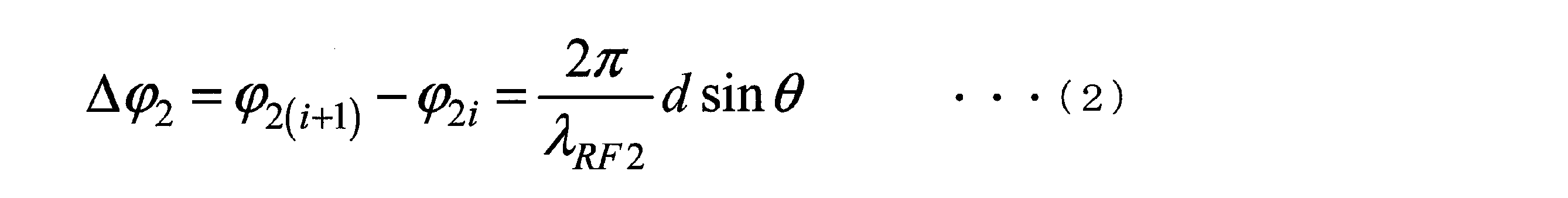
従って、φ2i=φ21+(i-1)Δφ2(i=1,…,n)となる。基地局40のE/O変換器44-i(i=1,…,n)は、アンテナ素子43-iが受信した位相φ2iの受信RF信号を用いて波長λ2iの光信号を変調し、光合成器45により波長多重して1本の光ファイバ30で収容局20まで伝送する。このとき、光ファイバ30の距離情報は分からなくてもよい。
波長λ21,…,λ2nの光変調信号を光ファイバ伝送すると、波長分散の影響を受けてそれぞれ異なる遅延差を生じ、異なる位相回転を受ける。波長λ21,…,λ2nは十分に小さい波長間隔で等間隔に配置されているため、波長分散による遅延差も等間隔となり、波長λ21,…,λ2nの光変調信号のRF信号としての位相回転量も等間隔となる。つまり、波長λ21,…,λ2nの光変調信号のRF信号としての位相回転量β21,…,β2nはそれぞれ、β21,β21-Δβ2,β21-2Δβ2,…,β21-(n-1)Δβ2となる。位相回転量β2iは、β2i=β21-(i-1)Δβ2(i=1,…,n)と表現できる。波長λ21,…,λ2nは固定されているため、RF信号としての位相回転量β21,…,β2nは定数となる。しかし、光ファイバ30の距離情報が分からない場合は、RF信号としての位相回転量β21,…,β2nの値を具体的に求めることはできない。
収容局20が受信した波長λ21,λ22,λ23,…,λ2nの光変調信号のRF信号としての位相は、φ21+β21,φ21+β21+Δφ2-Δβ2,φ21+β21+2(Δφ2-Δβ2),…,φ21+β21+(n-1)(Δφ2-Δβ2)となる。
これらの波長λ21,…,λ2nの光変調信号に対し、収容局20は、RF信号としてそれぞれ0,α2,2α2,…,(n-1)α2と等間隔になるように位相調整を行う。つまり、位相調整部24は、光分波器23が分波した波長λ2iの光変調信号に対して、RF信号として(i-1)α2の位相調整を行う。すると、波長λ21,λ22,λ23,…,λ2nの光変調信号のRF信号としての位相は、φ21+β21,φ21+β21+Δφ2-Δβ2+α2,φ21+β21+2(Δφ2-Δβ2+α2),…,φ21+β21+(n-1)(Δφ2-Δβ2+α2)となる。このとき、α2=Δβ2-Δφ2とすれば、波長λ21,…,λ2nの光変調信号のRF信号としての位相はφ21+β21で同相となり、方向θに受信アンテナのビームが形成される。収容局20は、これらの位相調整を波長λ21,…,λ2nの光変調信号に対してではなく、これら光変調信号をE/O変換した後の電気信号に対して行ってもよい。
これらの波長λ21,…,λ2nの光変調信号に対し、収容局20は、RF信号としてそれぞれ0,α2,2α2,…,(n-1)α2と等間隔になるように位相調整を行う。つまり、位相調整部24は、光分波器23が分波した波長λ2iの光変調信号に対して、RF信号として(i-1)α2の位相調整を行う。すると、波長λ21,λ22,λ23,…,λ2nの光変調信号のRF信号としての位相は、φ21+β21,φ21+β21+Δφ2-Δβ2+α2,φ21+β21+2(Δφ2-Δβ2+α2),…,φ21+β21+(n-1)(Δφ2-Δβ2+α2)となる。このとき、α2=Δβ2-Δφ2とすれば、波長λ21,…,λ2nの光変調信号のRF信号としての位相はφ21+β21で同相となり、方向θに受信アンテナのビームが形成される。収容局20は、これらの位相調整を波長λ21,…,λ2nの光変調信号に対してではなく、これら光変調信号をE/O変換した後の電気信号に対して行ってもよい。
先に述べた通り、光ファイバ30の距離情報が分からない場合は、RF信号としての位相回転量β21,…,β2nの値を具体的に求めることはできない。そのため、Δβ2は具体的な値の分からない定数となり、受信ビーム方向をθとするα2=Δβ2-Δφ2の値は具体的に求めることはできない。そこで、α2の値を走査し、受信電力最大となるα2=Δβ2-Δφ2の値を求める。α2の値を制御するのは収容局20であるため、受信ビーム方向制御に基地局40の制御は基本的には一切必要ない。
[2.3 送信アンテナ/受信アンテナのビーム方向決定フロー]
図5は、基地局40から送信されるp個(pは2以上の整数)のビーコンB(1),…,B(p)を示す図である。収容局20は、RF信号としてp個のビーコンB(1),…,B(p)を生成する。収容局20は、ビーコンB(j)(j=1,…,p)により変調した波長λ11,…,λ1nの光変調ビーコンB(j)を生成する。光変調ビーコンB(1),…,B(p)を光ファイバ伝送する前に、収容局20の位相調整部21は、それぞれα1の値として相異なる値α11,…,α1pを用いて位相調整を行う。つまり、収容局20の位相調整部21は、ビーコンB(j)(j=1,…,p)により変調した波長λ1i(i=1,…,n)の光変調ビーコンB(j)に対して、(i-1)α1jの位相調整を行う。
図5は、基地局40から送信されるp個(pは2以上の整数)のビーコンB(1),…,B(p)を示す図である。収容局20は、RF信号としてp個のビーコンB(1),…,B(p)を生成する。収容局20は、ビーコンB(j)(j=1,…,p)により変調した波長λ11,…,λ1nの光変調ビーコンB(j)を生成する。光変調ビーコンB(1),…,B(p)を光ファイバ伝送する前に、収容局20の位相調整部21は、それぞれα1の値として相異なる値α11,…,α1pを用いて位相調整を行う。つまり、収容局20の位相調整部21は、ビーコンB(j)(j=1,…,p)により変調した波長λ1i(i=1,…,n)の光変調ビーコンB(j)に対して、(i-1)α1jの位相調整を行う。
収容局20の光合成器22は、位相調整部21により位相調整された波長λ11,…,λ1nの光変調ビーコンB(j)を波長多重し、光ファイバ30により基地局40まで伝送する。基地局40の光分波器41は、光ファイバ30を伝送した波長多重光信号を、波長λ11,…,λ1nの光変調ビーコンB(j)に分波する。O/E変換器42-iは、波長λ1iの光変調ビーコンB(j)を光信号から電気信号のビーコンB(j)に変換し、アンテナ素子43-iは電気信号に変換された波長λ1iの光変調ビーコンB(j)を放射する。これにより、アンテナ素子43-1,…,43-nからビーコンB(j)が放射される。このとき、ビーコンB(j)は、以下の式(3)を満たす方向θjに放射される。
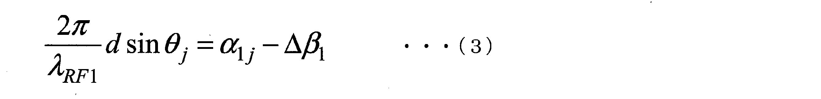
以上をp個のビーコンB(1),…,B(p)について行うことで、図5に示すように、基地局40から相異なるp通りの方向θ1,…,θpそれぞれに、ビーコンB(1),…,B(p)を送信することができる。
端末50は、基地局40から放射されたp個のビーコンB(1),…,B(p)を受信し、その中で受信電力が最大となったビーコンB(j)(j=1,…,p)を選択し、そのビーコン番号情報を基地局40にフィードバックする。このとき、端末50はビーコン番号情報をq回(qは2以上の整数)送信する。ビーコン番号情報は、ビーコンB(1),…,B(p)を一意に識別する情報の例である。以下では、ビーコンB(j)のビーコン番号情報をjとする。
基地局40は、端末50からフィードバックされたビーコン番号情報をE/O変換器44-1、…、44-nにより電気信号から光信号に変換し、そのまま光合成器45により波長合成したのち、光ファイバ30を介して収容局20に送信する。
収容局20の位相調整部24は、q回受信するビーコン番号情報それぞれに対して、α2の値として相異なる値α21,…,α2qを用いて位相調整を行いながら、受信電力を求める。収容局20は、α21,…,α2qの中で受信電力が最大となったときのα2k(k=1,…,q)を選択してα2の値とすることにより、受信アンテナのビーム方向を決定する。また、収容局20は、受信したビーコン番号情報を基にα1の値を決定し、送信アンテナのビーム方向を決定する。すなわち、収容局20は、ビーコン番号情報がjである場合、α1の値をα1jに決定する。
図6は、無線通信システム10におけるビーム方向決定のフローを示す図である。図6は、収容局20、基地局40及び端末50それぞれにおける上記の動作を、同一時間軸上で示している。収容局20は、α11,…,α1pそれぞれをα1に用いて位相調整した光変調ビーコンB(1),…,B(p)を生成し、基地局40に送信する(ステップS11)。基地局40は、受信した光変調ビーコンB(1),…,B(p)をO/E変換してRF信号とし(ステップS12)、RF信号に変換されたビーコンB(1),…,B(p)それぞれを異なるタイミングで送信する(ステップS13)。
端末50は、ビーコンB(1),…,B(p)を受信し、その中で受信電力が最大となったビーコンB(j)(j=1,…,p)を選択する(ステップS14)。端末50は、選択したビーコンB(j)を特定するビーコン番号情報をq回、基地局40に送信する(ステップS15)。基地局40は、受信したq個のビーコン番号情報をE/O変換し(ステップS16)、収容局20に送信する(ステップS17)。収容局20は、q個のビーコン番号情報を、α21,…,α2qのようにα2の値を走査しながら受信し、受信電力が最大となるα2k(k=1,…,q)の値を選択してα2の値として決定する。これにより、収容局20は、受信ビーム方向を決定する(ステップS18)。また、収容局20は、受信したビーコン番号情報jが示すビーコンB(j)を送信したときに用いたα1jにα1の値を決定する。これにより、収容局20は、送信ビーム方向を決定する(ステップS19)。
なお、基地局40は、収容局20および端末50から受信した信号をO/E変換およびE/O変換するのみで、基本的には一切の位相調整の制御を必要としない。
[3. 装置構成]
本実施形態の無線通信システム10に用いられる各装置の構成について説明する。
本実施形態の無線通信システム10に用いられる各装置の構成について説明する。
[3.1 収容局の構成]
図7は、収容局20の構成を示すブロック図であり、本実施形態と関係する機能ブロックのみを抽出して示してある。収容局20は、送信部210と、送信位相制御部220と、受信部230と、受信位相制御部240と、光サーキュレータ250とを備える。
図7は、収容局20の構成を示すブロック図であり、本実施形態と関係する機能ブロックのみを抽出して示してある。収容局20は、送信部210と、送信位相制御部220と、受信部230と、受信位相制御部240と、光サーキュレータ250とを備える。
送信部210は、波長λ11,…,λ1nの送信光変調信号を生成する。送信部210は、送信光変調信号の位相調整のために、各波長の光をRF信号により変調した光変調信号に対して位相調整を行う。この場合、送信部210として、後述する図8に示す第一送信部211を用いることができる。あるいは、送信部210は、送信光変調信号の位相調整のために、各波長の光の変調に用いるために分岐したRF信号に対して位相調整を行い、位相調整されたRF信号により各波長の光を変調する。この場合、送信部210として、後述する図9に示す第二送信部212を用いることができる。送信位相制御部220は、送信部210に対して位相調整の大きさを指示する。
受信部230は、波長λ21,…,λ2nの受信光変調信号に対して位相調整を行い、復調信号を得る。受信部230は、受信光変調信号の位相調整のために、分波した光変調信号それぞれに対して位相調整を行う。この場合、受信部230として、後述する図10に示す第一受信部231を用いることができる。あるいは、受信部230は、受信光変調信号の位相調整のために、分波した各光変調信号をO/E変換して得られたRF信号に対して位相調整を行う。この場合、受信部230として、後述する図11に示す第二受信部232を用いることができる。受信位相制御部240は、受信部230に対して位相調整の大きさを指示する。
光サーキュレータ250は、送信部210が出力した送信光変調信号を入力して光ファイバ30に出力し、光ファイバ30を伝送した受信光変調信号を入力して受信部230に出力する。
図8は、第一送信部211の構成を示すブロック図である。第一送信部211は、多波長光源2111と、光変調部2112と、光分波器2113と、位相調整部2114-2,…,2114-nと、光合成器2115とを備える。多波長光源2111は、波長λ11,…,λ1nの光を出力する。光変調部2112は、多波長光源2111が出力した波長λ11,…,λ1nの光をそれぞれRF信号により変調する。光分波器2113は、波長λ11,…,λ1nの光変調信号を分岐する。位相調整部2114-2,…,2114-nは、図2の位相調整部21に相当する。位相調整部2114-i(i=2,…,n)は、送信位相制御部220の制御に従って、波長λ1iの光変調信号に対して位相調整を行った後、光合成器2115に出力する。光合成器2115は、図2の光合成器22に相当する。光合成器2115は、光分波器2113が出力したλ11の光変調信号と、位相調整部2114-2,…,2114-nそれぞれが出力したλ12,…,λ1nの光変調信号とを合成し、光サーキュレータ250に出力する。光サーキュレータ250は、合成された光変調信号を光ファイバ30に出力する。
図9は、第二送信部212の構成を示すブロック図である。第二送信部212は、多波長光源2121と、光分波器2122と、分岐部2123と、位相調整部2124-2,…,2124-nと、光変調部2125-1,…,2125-nと、光合成器2126とを備える。多波長光源2121は、波長λ11,…,λ1nの光を出力する。光分波器2122は、波長λ11,…,λ1nの光変調信号を分岐する。分岐部2123は、RF信号をn個に分岐して、光変調部2125-1及び位相調整部2124-2,…,2124-nに出力する。位相調整部2124-2,…,2124-nは、図2の位相調整部21に相当する。位相調整部2124-i(i=2,…,n)は、送信位相制御部220の制御に従ってRF信号に対して位相調整を行った後、光変調部2125-iに出力する。光変調部2125-1は、光分波器2122が分波した波長λ11の光をRF信号により変調し、光合成器2126に出力する。光変調部2125-i(i=2,…,n)は、光分波器2122が分波した波長λ1iの光を、位相調整部2124-iが位相を調整したRF信号により変調し、光合成器2126に出力する。光合成器2126は、図2の光合成器22に相当する。光合成器2126は、光変調部2125-1,…,2125-nそれぞれが出力したλ11,…,λ1nの光変調信号を合成し、光サーキュレータ250に出力する。光サーキュレータ250は、合成された光変調信号を光ファイバ30に出力する。
図10は、第一受信部231の構成を示すブロック図である。第一受信部231は、光分波器2311と、位相調整部2312-2,…,2312-nと、光合成器2313と、O/E変換器2314と、受信電力計算部2315と、復調部2316とを備える。光分波器2311は、基地局40が出力した受信光変調信号を光サーキュレータ250から受信し、波長λ22,…,λ2nの光変調信号に分岐する。位相調整部2312-2,…,2312-nは、図4の位相調整部24に相当する。位相調整部2312-i(i=2,…,n)は、受信位相制御部240の制御に従って、波長λ2iの光変調信号に対して位相調整を行った後、光合成器2313に出力する。光合成器2313は、光分波器2311が出力した波長λ21の光変調信号と、位相調整部2312-2,…,2312-nそれぞれが出力した波長λ22,…,λ2nの光変調信号とを合成し、O/E変換器2314に出力する。O/E変換器2314は、光合成器2313が合成した光変調信号を電気信号に出力し、受信電力計算部2315及び復調部2316に出力する。受信電力計算部2315は、O/E変換器2314から入力した電気信号の受信電力を計算し、計算結果を受信位相制御部240に出力する。復調部2316は、電気信号に変換された受信信号を復調する。復調部2316は、復調により、端末50が送信したビーコン番号情報を得ると、得られたビーコン番号情報を送信位相制御部220に出力する。
図11は、第二受信部232の構成を示すブロック図である。第二受信部232は、光分波器2321と、O/E変換器2322-1,…,2322-nと、位相調整部2323-2,…,2323-nと、受信電力計算部2324と、復調部2325とを備える。
光分波器2321は、基地局40が出力した受信光変調信号を光サーキュレータ250から受信し、波長λ22,…,λ2nの光変調信号に分岐する。O/E変換器2322-i(i=1,…,n)は、光分波器2321が分波した波長λ2iの光変調信号を電気信号に変換する。位相調整部2323-i(i=2,…,n)は、受信位相制御部240の制御に従って、O/E変換器2322-iが出力した電気信号に対して位相調整を行う。受信電力計算部2324は、O/E変換器2322-1が出力した電気信号と、位相調整部2323-2,…,2323-nそれぞれが出力した電気信号とを用いて受信電力を計算し、計算結果を受信位相制御部240に出力する。復調部2325は、O/E変換器2322-1が出力した電気信号と、位相調整部2323-2,…,2323-nそれぞれが出力した電気信号とを用いて、端末50から送信された信号を復調する。復調部2325は、復調により、端末50が送信したビーコン番号情報を得ると、得られたビーコン番号情報を送信位相制御部220に出力する。
光分波器2321は、基地局40が出力した受信光変調信号を光サーキュレータ250から受信し、波長λ22,…,λ2nの光変調信号に分岐する。O/E変換器2322-i(i=1,…,n)は、光分波器2321が分波した波長λ2iの光変調信号を電気信号に変換する。位相調整部2323-i(i=2,…,n)は、受信位相制御部240の制御に従って、O/E変換器2322-iが出力した電気信号に対して位相調整を行う。受信電力計算部2324は、O/E変換器2322-1が出力した電気信号と、位相調整部2323-2,…,2323-nそれぞれが出力した電気信号とを用いて受信電力を計算し、計算結果を受信位相制御部240に出力する。復調部2325は、O/E変換器2322-1が出力した電気信号と、位相調整部2323-2,…,2323-nそれぞれが出力した電気信号とを用いて、端末50から送信された信号を復調する。復調部2325は、復調により、端末50が送信したビーコン番号情報を得ると、得られたビーコン番号情報を送信位相制御部220に出力する。
[3.2 基地局の構成]
図12は、基地局40の構成を示すブロック図であり、本実施形態と関係する機能ブロックのみを抽出して示してある。基地局40は、光分波器41と、O/E変換器42-1,…,42-nと、アンテナ素子43-1,…,43-nと、E/O変換器44-1,…,44-nと、光合成器45と、光サーキュレータ46と、電気サーキュレータ47-1,…,47-nとを有する。
図12は、基地局40の構成を示すブロック図であり、本実施形態と関係する機能ブロックのみを抽出して示してある。基地局40は、光分波器41と、O/E変換器42-1,…,42-nと、アンテナ素子43-1,…,43-nと、E/O変換器44-1,…,44-nと、光合成器45と、光サーキュレータ46と、電気サーキュレータ47-1,…,47-nとを有する。
光分波器41は、光ファイバ30を伝送した波長λ11,…,λ1nの光変調信号を分岐し、波長λ1i(i=1,…,n)の光変調信号をO/E変換器42-iに出力する。
O/E変換器42-i(i=1,…,n)は、波長λ1iの光変調信号をRF信号に変換し、アンテナ素子43-iに出力する。アンテナ素子43-i(i=1,…,n)は、O/E変換器42-iが出力したRF信号を放射する。また、アンテナ素子43-i(i=1,…,n)は、無線により受信したRF信号をE/O変換器44-iに出力する。E/O変換器44-i(i=1,…,n)は、アンテナ素子43-iが受信したRF信号を用いて波長λ2iの光を変調することにより、RF信号を光信号に変換し、光合成器45に出力する。光合成器45は、E/O変換器44-1,…,44-nそれぞれから出力された波長λ21,…,λ2nの光変調信号を合成した受信光変調信号を出力する。
O/E変換器42-i(i=1,…,n)は、波長λ1iの光変調信号をRF信号に変換し、アンテナ素子43-iに出力する。アンテナ素子43-i(i=1,…,n)は、O/E変換器42-iが出力したRF信号を放射する。また、アンテナ素子43-i(i=1,…,n)は、無線により受信したRF信号をE/O変換器44-iに出力する。E/O変換器44-i(i=1,…,n)は、アンテナ素子43-iが受信したRF信号を用いて波長λ2iの光を変調することにより、RF信号を光信号に変換し、光合成器45に出力する。光合成器45は、E/O変換器44-1,…,44-nそれぞれから出力された波長λ21,…,λ2nの光変調信号を合成した受信光変調信号を出力する。
光サーキュレータ46は、光ファイバ30を伝送した送信光変調信号を入力して光分波器41に出力する。また、光サーキュレータ46は、光合成器45が合成した受信光変調信号を入力して光ファイバ30に出力する。電気サーキュレータ47-i(i=1,…,n)は、O/E変換器42-iが出力したRF信号を入力し、アンテナ素子43-iに出力する。また、電気サーキュレータ47-i(i=1,…,n)は、アンテナ素子43-iが受信したRF信号を入力し、E/O変換器44-iに出力する。
[3.3 端末の構成]
図13は、端末50の構成を示すブロック図であり、本実施形態と関係する機能ブロックのみを抽出して示してある。端末50は、アンテナ素子51-1,…,51-m(mは1以上の整数)と、電気サーキュレータ52-1,…,52-mと、受信アンテナ制御部53と、受信電力計算部54と、復調部55と、受信電力最大ビーコン選択部56と、送信アンテナ制御部57とを備える。
図13は、端末50の構成を示すブロック図であり、本実施形態と関係する機能ブロックのみを抽出して示してある。端末50は、アンテナ素子51-1,…,51-m(mは1以上の整数)と、電気サーキュレータ52-1,…,52-mと、受信アンテナ制御部53と、受信電力計算部54と、復調部55と、受信電力最大ビーコン選択部56と、送信アンテナ制御部57とを備える。
アンテナ素子51-1,…,51-mは、無線により受信したRF信号を受信アンテナ制御部53に出力する。また、アンテナ素子51-1,…,51-mは、送信アンテナ制御部57が出力したRF信号を放射する。電気サーキュレータ52-i(i=1,…,m)は、アンテナ素子51-iが受信したRF信号を入力して受信アンテナ制御部53に出力し、送信アンテナ制御部57が出力したRF信号を入力してアンテナ素子51-iに出力する。受信アンテナ制御部53は、端末50の受信アンテナのビームフォーミングを制御する機能などを有する。受信電力計算部54は、受信したビーコンの受信電力を計算し、計算結果を受信電力最大ビーコン選択部56に出力する。復調部55は、受信信号を復調する。復調部55は、ビーコンを復調した場合、そのビーコンに含まれる情報から得られるビーコン番号情報を受信電力最大ビーコン選択部56に出力する。受信電力最大ビーコン選択部56は、受信電力計算部54が計算した受信電力に基づいて、受信電力が最大のビーコンのビーコン番号情報を取得し、送信アンテナ制御部57に出力する。送信アンテナ制御部57は、ビーコン番号情報を設定したRF信号をp回、アンテナ素子51-1,…,51-mから送信するよう制御する。また、送信アンテナ制御部57は、端末50の送信アンテナのビームフォーミングを制御する機能などを有する。
[4.無線通信システムの動作]
続いて、無線通信システム10の動作について説明する。
続いて、無線通信システム10の動作について説明する。
[4.1 第一送信部及び第一受信部を用いた場合(動作例1)]
動作例1では、収容局20の送信部210、受信部230として、図8に示す第一送信部211、図10に示す第一受信部231を用いる。収容局20は、送信光変調信号および受信光変調信号の位相調整のために、各波長の光変調信号に対して位相調整を行う。
動作例1では、収容局20の送信部210、受信部230として、図8に示す第一送信部211、図10に示す第一受信部231を用いる。収容局20は、送信光変調信号および受信光変調信号の位相調整のために、各波長の光変調信号に対して位相調整を行う。
[4.1.1 送信アンテナのビームフォーミング]
収容局20の多波長光源2111は、n個の相異なる波長λ11,…,λ1nの光信号を生成する。ここで、波長λ11,…,λ1nは、十分に小さい波長間隔で等間隔に配置されているものとする。つまり、十分に小さい波長間隔Δλ1について、λ1i=λ11+(i-1)Δλ1が成立しているものとする。波長λ11,…,λ1nの光信号は、1つの光変調部2112に入力される。光変調部2112は、入力されるRF信号を用いて、多波長光源2111から入力された波長λ11,…,λ1nの光信号を変調し、波長λ11,…,λ1nの光変調信号を出力する。
収容局20の多波長光源2111は、n個の相異なる波長λ11,…,λ1nの光信号を生成する。ここで、波長λ11,…,λ1nは、十分に小さい波長間隔で等間隔に配置されているものとする。つまり、十分に小さい波長間隔Δλ1について、λ1i=λ11+(i-1)Δλ1が成立しているものとする。波長λ11,…,λ1nの光信号は、1つの光変調部2112に入力される。光変調部2112は、入力されるRF信号を用いて、多波長光源2111から入力された波長λ11,…,λ1nの光信号を変調し、波長λ11,…,λ1nの光変調信号を出力する。
一般に、光信号をRF信号で変調した信号はDSB(double side band)信号となる。
このDSB信号を光ファイバ伝送すると、波長分散の影響を受け、下側波帯と上側波帯との間に遅延差が生じ、フェージングが発生する。そのため、伝送可能な光ファイバ長が制限されてしまう。RF信号の周波数が高くなるほど、側波帯間の間隔が広くなるため、フェージングの影響が顕著になる。この波長分散によるフェージングを回避するため、光変調部2112は、光変調信号をSSB(single side band)信号や2トーン信号にするなど、波長分散によるフェージング対策を行う機能を有していてもよい。
このDSB信号を光ファイバ伝送すると、波長分散の影響を受け、下側波帯と上側波帯との間に遅延差が生じ、フェージングが発生する。そのため、伝送可能な光ファイバ長が制限されてしまう。RF信号の周波数が高くなるほど、側波帯間の間隔が広くなるため、フェージングの影響が顕著になる。この波長分散によるフェージングを回避するため、光変調部2112は、光変調信号をSSB(single side band)信号や2トーン信号にするなど、波長分散によるフェージング対策を行う機能を有していてもよい。
光分波器2113は、波長λ11,…,λ1nの光変調信号を固定的に分岐する。波長λ11の光変調信号はそのまま光合成器2115に送られ、波長λ12,…,λ1nの光変調信号はそれぞれ位相調整部2114-2,…,2114-nに送られる。このとき、光分岐は固定的なため、光分波器2113の制御は必要ない。
送信位相制御部220は、n-1個の位相調整部2114-2,…,2114-nに対してα1の値を入力する。波長λ11,λ12,λ13,…,λ1nの光変調信号へのRF信号としての位相調整量は、それぞれ0,α1,2α1,…,(n-1)α1であり、α1間隔である。すなわち、波長λ1i(i=1,…,n)の光変調信号に対して、RF信号として(i-1)α1の位相調整が行われるものとみなすことができる。波長λ13,…,λ1nの光変調信号の位相調整量は、波長λ12の光変調信号の位相調整量α1が決定されれば自動的に決定される。つまり、位相調整部2114-i(i=2,…,n)は、入力された波長λ1iの光変調信号に対して、RF信号として(i-1)α1の位相調整を行い、光合成器2115に出力する。
光合成器2115は、波長λ11の光変調信号と、位相調整された波長λ12,…,λ1nの光変調信号を合成する。合成された光変調信号は、光サーキュレータ250及び光ファイバ30を経て、基地局40に送られる。このとき、光ファイバ30の距離情報は分からなくてもよい。
波長λ11,…,λ1nの光変調信号を光ファイバ伝送すると、波長分散の影響を受けてそれぞれ異なる遅延差が生じ、異なる位相回転を受ける。波長λ11,…,λ1nは十分に小さい波長間隔で等間隔に配置されているため、波長分散による遅延差も等間隔にすることができ、波長λ11,…,λ1nの光変調信号のRF信号としての位相回転量も等間隔となる。つまり、波長λ11,…,λ1nの光変調信号のRF信号としての位相回転量β11,…,β1nはそれぞれ、β11,β11-Δβ1,β11-2Δβ1,…,β11-(n-1)Δβ1となり、β1i=β11-(i-1)Δβ1と表現できる。波長λ11,…,λ1nは固定されているため、RF信号としての位相回転量β11,…,β1nは定数となる。しかし、光ファイバ30の距離情報が分からない場合は、RF信号としての位相回転量β11,…,β1nの値を具体的に求めることはできない。
収容局20から基地局40に光ファイバ伝送された波長λ11,…,λ1nの光変調信号は、光サーキュレータ46を経て光分波器41で固定的に分岐され、それぞれアンテナ素子43-1,…,43-nに向けて送られる。このとき、光分岐は固定的なため、光分波器41の制御は必要ない。
O/E変換器42-1,…,42-nはそれぞれ、O/E変換により波長λ11,…,λ1nの光変調信号をRF信号に変換する。波長λ1iの光変調信号は、収容局20においてRF信号として(i-1)α1の位相調整が行われており、光ファイバ伝送中にRF信号としてβ1i=β11-(i-1)Δβ1の位相回転がかかっている。その位相φ1iは、φ1i=(i-1)α1+β1i=β11+(i-1)(α1-Δβ1)となり、この位相のRF信号がアンテナ素子43-iから放射される。
隣接するアンテナ素子43-iとアンテナ素子43-(i+1)から放射される送信RF信号の位相差は、φ1(i+1)-φ1i=α1-Δβ1となり、隣接するアンテナ素子間の位相差がα1-Δβ1で一定となっている。アンテナ素子43-1,…,43-nが等間隔dで配列されているものとすると、送信RF信号の波長をλRF1とし、図3のように送信ビーム方向θを定義すれば、上記の式(1)を満たす方向に送信ビームが形成される。
送信RF信号の波長λRF1、アンテナ素子間隔dは既知の定数である。波長λ11,…,λ1nは固定的であるためΔβ1も定数となるが、光ファイバ30の距離情報が分からない場合は、RF信号としての位相回転量β11,…,β1nの値を具体的に求めることはできず、Δβ1の具体的な値を求めることもできない。よって、送信ビーム方向θを規定するのはα1のみとなる。これは、α1を変化させることで、ある方向θに送信ビームを形成することができるが、その具体的な方向は分からないことを意味する。ただし、α1を制御するのは収容局20のみであるため、送信ビーム形成のための基地局40の制御は基本的には一切必要ない。
上記のように、光ファイバ30の距離情報が分からない場合は、基地局40が形成した送信ビーム方向θは分からない。従って、その送信ビーム方向の決定には、基地局40の通信相手である端末50のフィードバックが必要となる。その送信ビーム方向決定フローについては、受信アンテナのビームフォーミングについて述べた後、詳しく述べる。
[4.1.2 受信アンテナのビームフォーミング]
基地局40のn個のアンテナ素子43-1,…,43-nが端末50からのRF信号を受信すると、受信RF信号は電気サーキュレータ47-1,…,47-nを経て、E/O変換器44-1,…,44-nに送られる。アンテナ素子43-1,…,43-nに対応するE/O変換器44-1,…,44-nは、それぞれ受信RF信号により波長λ21,…,λ2nの光信号を変調し、波長λ21,…,λ2nの光変調信号を出力する。ここで、波長λ21,…,λ2nは、十分に小さい波長間隔で等間隔に配置されているものとする。つまり、十分に小さい波長間隔Δλ2について、λ2i=λ21+(i-1)Δλ2が成立しているものとする。
基地局40のn個のアンテナ素子43-1,…,43-nが端末50からのRF信号を受信すると、受信RF信号は電気サーキュレータ47-1,…,47-nを経て、E/O変換器44-1,…,44-nに送られる。アンテナ素子43-1,…,43-nに対応するE/O変換器44-1,…,44-nは、それぞれ受信RF信号により波長λ21,…,λ2nの光信号を変調し、波長λ21,…,λ2nの光変調信号を出力する。ここで、波長λ21,…,λ2nは、十分に小さい波長間隔で等間隔に配置されているものとする。つまり、十分に小さい波長間隔Δλ2について、λ2i=λ21+(i-1)Δλ2が成立しているものとする。
基地局40において、端末50からの信号が図3のような方向θから到来したとする。
アンテナ素子43-iで受信したRF信号の位相をφ2iとすると、受信RF信号の波長をλRF2とした場合に、上記の式(2)が成立し、φ2i=φ21+(i―1)Δφ2と表せる。つまり、アンテナ素子43-iに対応するE/O変換器44-iは、位相φ2iの受信RF信号で波長λ2iの光信号を変調して波長λ2iの光変調信号を出力する。
光合成器45は、波長λ21,…,λ2nの光変調信号を合成する。合成された光変調信号は、光サーキュレータ46及び光ファイバ30を経て収容局20に送られる。このとき、光ファイバ30の距離情報は分からなくてもよい。
アンテナ素子43-iで受信したRF信号の位相をφ2iとすると、受信RF信号の波長をλRF2とした場合に、上記の式(2)が成立し、φ2i=φ21+(i―1)Δφ2と表せる。つまり、アンテナ素子43-iに対応するE/O変換器44-iは、位相φ2iの受信RF信号で波長λ2iの光信号を変調して波長λ2iの光変調信号を出力する。
光合成器45は、波長λ21,…,λ2nの光変調信号を合成する。合成された光変調信号は、光サーキュレータ46及び光ファイバ30を経て収容局20に送られる。このとき、光ファイバ30の距離情報は分からなくてもよい。
波長λ21,…,λ2nの光変調信号を光ファイバ伝送すると、波長分散の影響を受けてそれぞれ異なる遅延差が生じ、異なる位相回転を受ける。波長λ21,…,λ2nは十分に小さい波長間隔で等間隔に配置されているため、波長分散による遅延差も等間隔にすることができ、波長λ21,…,λ2nの光変調信号のRF信号としての位相回転量も等間隔となる。つまり、波長λ21,…,λ2nの光変調信号のRF信号としての位相回転量β21,…,β2nはそれぞれ、β21,β21-Δβ2,β21-2Δβ2,…,β21-(n-1)Δβ2となり、β2i=β21-(i-1)Δβ2と表現できる。波長λ21,…,λ2nは固定されているため、RF信号としての位相回転量β21,…,β2nは定数となる。しかし、光ファイバ30の距離情報が分からない場合は、RF信号としての位相回転量β21,…,β2nの値を具体的に求めることはできない。
収容局20が受信した波長λ21,λ22,λ23,…,λ2nの光変調信号のRF信号としての位相は、φ21+β21,φ21+β21+Δφ2-Δβ2,φ21+β21+2(Δφ2-Δβ2),…,φ21+β21+(n-1)(Δφ2-Δβ2)となる。
基地局40から光ファイバ伝送された波長λ21,…,λ2nの光変調信号は、収容局20の光サーキュレータ250を経て第一受信部231の光分波器2311で固定的に分岐される。波長λ21の光変調信号はそのまま光合成器2313に送られ、波長λ22,…,λ2nの光変調信号はそれぞれ、位相調整部2312-2,…,2312-nに送られる。このとき、光分岐は固定的なため、光分波器2311の制御は必要ない。
受信位相制御部240は、n-1個の位相調整部2312-2,…,2312-nに対して、α2の値を入力する。波長λ21,λ22,λ23,…,λ2nの光変調信号へのRF信号としての位相調整量は、それぞれ0,α2,2α2,…,(n-1)α2であるためα2間隔となる。すなわち、波長λ2i(i=1,…,n)の光変調信号に対してRF信号として(i-1)α2の位相調整が行われるものとみなすことができる。波長λ23,…,λ2nの光変調信号の位相調整量は、波長λ22の光変調信号の位相調整量α2が決定されれば自動的に決定される。つまり、位相調整部2312-i(i=2,…,n)は、入力される波長λ2iの光変調信号に対して、RF信号として(i-1)α2の位相調整を行う。
以上の位相調整を行うと、波長λ21,λ22,λ23,…,λ2nの光変調信号のRF信号としての位相はそれぞれ、φ21+β21,φ21+β21+Δφ2-Δβ2+α2,φ21+β21+2(Δφ2-Δβ2+α2),…,φ21+β21+(n-1)(Δφ2-Δβ2+α2)となる。このとき、α2=Δβ2-Δφ2とすれば、波長λ21,…,λ2nの光変調信号のRF信号としての位相はφ21+β21で同相となり、方向θに受信アンテナのビームが形成される。先に述べた通り、光ファイバ30の距離情報が分からない場合は、RF信号としての位相回転量β21,…,β2nの値を具体的に求めることはできない。そのため、Δβ2は具体的な値の分からない定数となり、受信ビーム方向をθとするα2=Δβ2-Δφ2の値は具体的に求めることはできない。よって、α2の値を走査し、受信電力最大となるα2=Δβ2-Δφ2の値を求めることが必要となる。
ここで、受信ビーム方向θを規定する変数はα2のみとなり、α2の値を変化させることで受信ビーム方向θを変化させることができる。α2を制御するのは収容局20であるため、受信ビーム方向制御に基地局40の制御は基本的には一切必要ない。
[4.1.3 受信アンテナ/送信アンテナのビーム方向決定フロー]
受信アンテナ/送信アンテナのビーム方向決定フローは、上述した図6と同様である。
収容局20は、RF信号としてp個のビーコンB(1),…,B(p)を生成し、光変調部2112に順番に入力する。光変調部2112は、ビーコンB(j)(j=1,…,p)により多波長光源2111が出力した波長λ11,…,λ1nの光信号を変調し、波長λ11,…,λ1nの光変調ビーコンB(j)を出力する。
受信アンテナ/送信アンテナのビーム方向決定フローは、上述した図6と同様である。
収容局20は、RF信号としてp個のビーコンB(1),…,B(p)を生成し、光変調部2112に順番に入力する。光変調部2112は、ビーコンB(j)(j=1,…,p)により多波長光源2111が出力した波長λ11,…,λ1nの光信号を変調し、波長λ11,…,λ1nの光変調ビーコンB(j)を出力する。
光分波器2113は、波長λ11,…,λ1nの光変調ビーコンB(j)を分岐する。
波長λ11の光変調ビーコンB(j)はそのまま光合成器2115に出力される。位相調整部2114-2,…,2114-nはそれぞれ、送信位相制御部220からの制御に従ってα1=α1jとして、波長λ12,…,λ1nの光変調ビーコンB(j)に対して位相調整を行う。そのため、送信位相制御部220は、位相調整部2114-2,…,2114-nに、p個の光変調ビーコンB(1),…,B(p)のそれぞれに対応するα1の値として相異なる値α11,…,α1pを指示する。
波長λ11の光変調ビーコンB(j)はそのまま光合成器2115に出力される。位相調整部2114-2,…,2114-nはそれぞれ、送信位相制御部220からの制御に従ってα1=α1jとして、波長λ12,…,λ1nの光変調ビーコンB(j)に対して位相調整を行う。そのため、送信位相制御部220は、位相調整部2114-2,…,2114-nに、p個の光変調ビーコンB(1),…,B(p)のそれぞれに対応するα1の値として相異なる値α11,…,α1pを指示する。
光合成器2115は、それぞれ位相調整された波長λ11,…,λ1nの光変調ビーコンB(j)を合成する。合成された光変調ビーコンB(j)は、光ファイバ伝送された後、基地局40においてO/E変換され、ビーコンB(j)としてアンテナ素子43-1,…,43-nから放射される。このとき、ビーコンB(j)は、上述した式(3)を満たす方向θjに放射される。
無線通信システム10は、以上の動作をp個のビーコンB(1),…,B(p)について行うことで、図5に示すように、基地局40から相異なるp通りの方向θ1,…,θpにそれぞれビーコンB(1),…,B(p)を送信することができる(図6のステップS11~ステップS13)。
端末50のアンテナ素子51-1,…,51-mは、基地局40からp個のビーコンB(1),…,B(p)を受信する。受信アンテナ制御部53は、アンテナ素子51-1,…,51-mが受信したp個のビーコンB(1),…,B(p)を、受信電力計算部54と復調部55に出力する。受信電力計算部54は、受信したp個のビーコンB(1),…,B(p)それぞれの受信電力を計算し、その結果を出力する。復調部55は、受信したp個のビーコンB(1),…,B(p)それぞれを復調してビーコン番号を出力する。
受信電力最大ビーコン選択部56は、受信電力計算部54および復調部55よりそれぞれ入力されるビーコンの受信電力とビーコン番号に基づき、受信電力が最大となったビーコン番号を選択してそのビーコン番号情報を出力する(図6のステップS14)。送信アンテナ制御部57は、受信電力最大ビーコン選択部56が出力したビーコン番号情報を、アンテナ素子51-1,…,51-mから基地局40に送信するよう制御する。端末50は、このビーコン番号情報をq回送信する(図6のステップS15)。
基地局40のE/O変換器44-1,…,44-nは、アンテナ素子43-1,…,43-nが端末50から受信したビーコン番号情報をE/O変換する(図6のステップS16)。光合成器45は、このE/O変換により得られた波長λ21,…,λ2nの光変調ビーコン番号情報を合成し、収容局20に送信する。基地局40は、端末50からビーコン番号情報をq回送信するため、収容局20に対して光変調ビーコン番号情報を異なるタイミングでq回送信する(図6のステップS17)。
収容局20の光分波器2311は、基地局40から送信された光変調ビーコン番号情報を、波長λ21,…,λ2nの光変調ビーコン番号情報に分岐する。波長λ21の光変調ビーコン番号情報はそのまま光合成器2313に送られ、波長λ22,…,λ2nの光変調ビーコン番号情報はそれぞれ位相調整部2312-2,…,2312-nにおいて位相調整が行われる。このとき、位相調整部2312-2,…,2312-nは、受信位相制御部240からの制御に従って、q回受信される光変調ビーコン番号情報に対し、それぞれ相異なるα2の値α21,…,α2qで位相調整を行う。そのため、受信位相制御部240は、光変調ビーコン番号情報の受信の度にα2値をα21,…,α2qと順に変更して位相調整部2312-2,…,2312-nに指示する。
光合成器2313は、波長λ21の光変調ビーコン番号情報と、位相調整部2312-2,…,2312-nそれぞれが位相調整を行った波長λ22,…,λ2nの光変調ビーコン番号情報を合成し、O/E変換器2314に出力する。O/E変換器2314は、合成された光変調ビーコン番号情報をO/E変換することにより、ビーコン番号情報を得る。O/E変換器2314は、ビーコン番号情報を、受信電力計算部2315及び復調部2316に出力する。
受信電力計算部2315は、それぞれ異なる位相調整が行われたq個のビーコン番号情報を受信し、その受信電力を計算して受信位相制御部240に通知する。受信位相制御部240は、通知された受信電力に基づき、受信電力が最大となったときのα2の値を決定する。このように、収容局20は、q個のビーコン番号情報をα2の値を走査しながら受信し、受信電力最大となるα2の値を選択して決定する。これにより、受信アンテナのビーム方向が決定される(図6のステップS18)。受信位相制御部240は、決定したα2の値を端末50からの信号受信時に用いるよう第一受信部231を制御する。
復調部2316は、受信したビーコン番号情報を復調し、送信位相制御部220に出力する。送信位相制御部220は、そのビーコン番号情報に基づいてα1の値を決定する。
これにより、送信アンテナのビーム方向が決定される(図6のステップS19)。送信位相制御部220は、決定したα1の値を端末50への信号送信時に用いるよう第一送信部211を制御する。
これにより、送信アンテナのビーム方向が決定される(図6のステップS19)。送信位相制御部220は、決定したα1の値を端末50への信号送信時に用いるよう第一送信部211を制御する。
よって、基地局40は、収容局20および端末50から受信した信号をO/E変換およびE/O変換すればよく、ビーム方向の制御についての制御を必要としない。
[4.2 第二送信部及び第二受信部を用いた場合(動作例2)]
動作例2では、収容局20の送信部210、受信部230として、図9に示す第二送信部212、図11に示す第二受信部232を用いる。収容局20は、送信光変調信号および受信光変調信号の位相調整のために、RF信号に対して位相調整を行う。
動作例2では、収容局20の送信部210、受信部230として、図9に示す第二送信部212、図11に示す第二受信部232を用いる。収容局20は、送信光変調信号および受信光変調信号の位相調整のために、RF信号に対して位相調整を行う。
[4.2.1 送信アンテナのビームフォーミング]
収容局20の多波長光源2121は、n個の相異なる波長λ11,…,λ1nの光信号を生成する。ここで、波長λ11,…,λ1nは、十分に小さい波長間隔で等間隔に配置されているものとする。つまり、十分に小さい波長間隔Δλ1について、λ1i=λ11+(i-1)Δλ1が成立しているものとする。光分波器2122は、波長λ11,…,λ1nの光信号を分岐し、それぞれ光変調部2125-1,…,2125-nに入力する。
収容局20の多波長光源2121は、n個の相異なる波長λ11,…,λ1nの光信号を生成する。ここで、波長λ11,…,λ1nは、十分に小さい波長間隔で等間隔に配置されているものとする。つまり、十分に小さい波長間隔Δλ1について、λ1i=λ11+(i-1)Δλ1が成立しているものとする。光分波器2122は、波長λ11,…,λ1nの光信号を分岐し、それぞれ光変調部2125-1,…,2125-nに入力する。
送信位相制御部220は、n-1個の位相調整部2124-2,…,2124-nに対して、α1の値を入力する。分岐部2123は、RF信号をn個に分岐して、光変調部2125-1及び位相調整部2124-2,…,2124-nに出力する。位相調整部2124-i(i=2,…,n)は、分岐部2123から入力されるRF信号に対し、(i-1)α1の位相調整を行い、RF信号(i)を出力する。
光変調部2125-1はRF信号により波長λ11の光信号を変調し、波長λ11の光変調信号を出力する。光変調部2125-i(i=2,…,n)は、RF信号(i)により波長λ1iの光信号を変調し、波長λ1iの光変調信号を出力する。動作例1と同様に、光変調部2125-1,…,2125-nは、波長分散によるフェージング対策を行う機能を有していてもよい。
光合成器2115は、波長λ11,…,λ1nの光変調信号を合成する。合成された光変調信号は、光サーキュレータ250及び光ファイバ30を経て、基地局40に送られる。このとき、光ファイバ30の距離情報は分からなくてもよい。
動作例1と同様に、波長λ11,…,λ1nの光変調信号を光ファイバ伝送すると、波長分散の影響を受けてそれぞれ異なる遅延差が生じ、異なる位相回転を受ける。波長λ11,…,λ1nは十分に小さい波長間隔で等間隔に配置されているため、波長分散による遅延差も等間隔にすることができ、波長λ11,…,λ1nの光変調信号のRF信号としての位相回転量も等間隔となる。つまり、波長λ11,…,λ1nの光変調信号のRF信号としての位相回転量β11,…,β1nはそれぞれ、β11,β11-Δβ1,β11-2Δβ1,…,β11-(n-1)Δβ1となり、β1i=β11-(i-1)Δβ1と表現できる。波長λ11,…,λ1nは固定されているため、RF信号としての位相回転量β11,…,β1nは定数となる。しかし、光ファイバの距離情報が分からない場合は、RF信号としての位相回転量β11,…,β1nの値を具体的に求めることはできない。
基地局40及び端末50の動作は、動作例1と同様である。すなわち、収容局20から基地局40に光ファイバ伝送された波長λ11,…,λ1nの光変調信号は、光サーキュレータ46を経て光分波器41で固定的に分岐される。光分岐は固定的なため、光分波器41の制御は必要ない。O/E変換器42-1,…,42-nはそれぞれ、光分波器41が分岐した波長λ11,…,λ1nの光変調信号をRF信号に変換する。波長λ1iの光変調信号は、収容局20においてRF信号として(i-1)α1の位相調整が行われており、光ファイバ伝送中にRF信号としてβ1i=β11-(i-1)Δβ1の位相回転がかかっている。その位相φ1iは、φ1i=(i-1)α1+β1i=β11+(i-1)(α1-Δβ1)となり、この位相のRF信号がアンテナ素子43-iから放射される。
動作例1と同様に、隣接するアンテナ素子43-iとアンテナ素子43-(i+1)から放射される送信RF信号の位相差は、φ1(i+1)-φ1i=α1-Δβ1となり、隣接するアンテナ素子間の位相差がα1-Δβ1で一定となっている。アンテナ素子43-1,…,43-nが等間隔dで配列されているものとすると、送信RF信号の波長をλRF1とし、図3のように送信ビーム方向θを定義すれば、上記の式(1)を満たす方向に送信ビームが形成される。
動作例1と同様に、送信RF信号の波長λRF1、アンテナ素子間隔dは既知の定数である。波長λ11,…,λ1nは固定的であるため、Δβ1も定数となるが、光ファイバ30の距離情報が分からない場合は、RF信号としての位相回転量β11,…,β1nの値を具体的に求めることはできず、Δβ1その具体的な値を求めることはできない。よって、送信ビーム方向θを規定するのはα1のみとなる。これは、α1を変化させることである方向θに送信ビームを形成することができるが、その具体的な方向は分からないことを意味する。ただし、α1を制御するのは収容局20のみであるため、送信ビーム形成のための基地局制御は一切必要ない。
動作例1と同様に、光ファイバの距離情報が分からない場合は、基地局40が形成した送信ビーム方向θが分からない。従って、その送信ビーム方向の決定には、基地局40の通信相手である端末50のフィードバックが必要となる。その送信ビーム方向決定フローについては、受信アンテナのビームフォーミングについて述べた後、詳しく述べる。
[4.2.2 受信アンテナのビームフォーミング]
基地局40のn個のアンテナ素子43-1,…,43-nが端末50からのRF信号を受信した場合の動作は、動作例1と同様である。すなわち、受信RF信号は電気サーキュレータ47-1,…,47-nを経て、E/O変換器44-1,…,44-nに送られる。E/O変換器44-1,…,44-nは、それぞれ受信RF信号で波長λ21,…,λ2nの光信号を変調し、波長λ21,…,λ2nの光変調信号を出力する。ここで、波長λ21,…,λ2nは、十分に小さい波長間隔で等間隔に配置されているものとする。つまり、十分に小さい波長間隔Δλ2について、λ2i=λ21+(i-1)Δλ2が成立しているものとする。
基地局40のn個のアンテナ素子43-1,…,43-nが端末50からのRF信号を受信した場合の動作は、動作例1と同様である。すなわち、受信RF信号は電気サーキュレータ47-1,…,47-nを経て、E/O変換器44-1,…,44-nに送られる。E/O変換器44-1,…,44-nは、それぞれ受信RF信号で波長λ21,…,λ2nの光信号を変調し、波長λ21,…,λ2nの光変調信号を出力する。ここで、波長λ21,…,λ2nは、十分に小さい波長間隔で等間隔に配置されているものとする。つまり、十分に小さい波長間隔Δλ2について、λ2i=λ21+(i-1)Δλ2が成立しているものとする。
動作例1と同様に、基地局40において、端末50からの信号が図3のような方向θから到来したとする。アンテナ素子43-iで受信したRF信号の位相をφ2iとした場合に、上記の式(2)が成立し、φ2i=φ21+(i―1)Δφ2と表せる。アンテナ素子43-iに対応するE/O変換器44-iは、位相φ2iの受信RF信号で波長λ2iの光信号を変調して波長λ2iの光変調信号を出力する。光合成器45は、波長λ21,…,λ2nの光変調信号を合成する。合成された光変調信号は、光サーキュレータ46及び光ファイバ30を経て収容局20に送られる。このとき、光ファイバ30の距離情報は分からなくてもよい。
動作例1と同様に、波長λ21,…,λ2nの光変調信号を光ファイバ伝送すると、波長分散の影響を受けてそれぞれ異なる遅延差が生じ、異なる位相回転を受ける。波長λ21,…,λ2nは十分に小さい波長間隔で等間隔に配置されているため、波長分散による遅延差も等間隔にすることができ、波長λ21,…,λ2nの光変調信号のRF信号としての位相回転量も等間隔となる。つまり、波長λ21,…,λ2nの光変調信号のRF信号としての位相回転量β21,…,β2nはそれぞれ、β21,β21-Δβ2,β21-2Δβ2,…,β21-(n-1)Δβ2となり、β2i=β21-(i-1)Δβ2と表現できる。波長λ21,…,λ2nは固定されているため、RF信号としての位相回転量β21,…,β2nは定数となる。しかし、光ファイバ30の距離情報が分からない場合は、RF信号としての位相回転量β21,…,β2nの値を具体的に求めることはできない。また、動作例1と同様に、収容局20が受信した波長λ21,λ22,λ23,…,λ2nの光変調信号のRF信号としての位相は、φ21+β21,φ21+β21+Δφ2-Δβ2,φ21+β21+2(Δφ2-Δβ2),…,φ21+β21+(n-1)(Δφ2-Δβ2)となる。
基地局40から光ファイバ伝送された波長λ21,…,λ2nの光変調信号は、収容局20の光サーキュレータ250を経て第二受信部232の光分波器2321で固定的に分岐される。O/E変換器2322-1,…,2322-nはそれぞれ、波長λ21,…,λ2nの光変調信号をO/E変換し、受信信号(1),…,受信信号(n)を得る。O/E変換器2322-i(i=1,…,n)は、O/E変換により得られた受信信号(i)を出力する。受信信号(2),…,受信信号(n)はそれぞれ、位相調整部2323-2,…,2323-nに入力される。
受信位相制御部240は、n-1個の位相調整部2323-2,…,2323-nに対して、α2の値を入力する。受信信号(1),受信信号(2),受信信号(3),…,受信信号(n)へのRF信号としての位相調整量はそれぞれ、0,α2,2α2,…,(n-1)α2であるためα2間隔となる。すなわち、受信信号(i)(i=1,…,n)に対してRF信号として(i-1)α2の位相調整が行われるものとみなすことができる。
受信信号(3),…,受信信号(n)の位相調整量は、受信信号(2)の位相調整量α2が決定されれば自動的に決定される。つまり、位相調整部2323-i(i=2,…,n)は、受信信号(i)に対して、RF信号として(i-1)α2の位相調整を行う。
受信信号(3),…,受信信号(n)の位相調整量は、受信信号(2)の位相調整量α2が決定されれば自動的に決定される。つまり、位相調整部2323-i(i=2,…,n)は、受信信号(i)に対して、RF信号として(i-1)α2の位相調整を行う。
以上の位相調整を行うと、受信信号(1),受信信号(2),受信信号(3),…,受信信号(n)のRF信号としての位相はそれぞれ、φ21+β21,φ21+β21+Δφ2-Δβ2+α2,φ21+β21+2(Δφ2-Δβ2+α2),…,φ21+β21+(n-1)(Δφ2-Δβ2+α2)となる。このとき、α2=Δβ2-Δφ2とすれば、受信信号(1),受信信号(2),受信信号(3),…,受信信号(n)のRF信号としての位相はφ21+β21で同相となり、方向θに受信アンテナのビームが形成される。先に述べた通り、光ファイバ30の距離情報が分からない場合は、RF信号としての位相回転量β21,…,β2nの値を具体的に求めることはできない。そのため、Δβ2は具体的な値の分からない定数となり、受信ビーム方向をθとするα2=Δβ2-Δφ2の値は具体的に求めることはできない。よって、α2の値を走査し、受信電力最大となるα2=Δβ2-Δφ2の値を求めることが必要となる。
ここで、動作例1と同様に、受信ビーム方向θを規定する変数はα2のみとなり、α2の値を変化させることで受信ビーム方向θを変化させることができる。α2を制御するのは収容局20であるため、受信ビーム方向制御に基地局40の制御は基本的には一切必要ない。
[4.2.3 受信アンテナ/送信アンテナのビーム方向決定フロー]
受信アンテナ/送信アンテナのビーム方向決定フローは、上述した図6と同様である。
収容局20は、RF信号としてp個のビーコンB(1),…,B(p)を生成し、分岐部2123は光変調部2125-1及び位相調整部2124-2,…,2124-nに順番に入力する。位相調整部2124-i(i=2,…,n)は、送信位相制御部220からの制御に従って、ビーコンB(j)(j=1,…,p)に対してα1=α1jとして位相調整を行う。そのため、送信位相制御部220は、位相調整部2124-2,…,2124-nに、p個のビーコンB(1),…,B(p)のそれぞれに対応するα1の値として相異なる値α11,…,α1pを指示する。
光変調部2125-1は、ビーコンB(j)を用いて波長λ1の光信号を変調し、波長λ11の光変調ビーコンB(j)を出力する。光変調部2125-i(i=2,…,n)は、位相調整部2124-iにより位相が変調されたビーコンB(j)を用いて波長λ1iの光信号を変調し、波長λ1iの光変調ビーコンB(j)を出力する。
光合成器2126は、それぞれ位相調整された波長λ11,…,λ1nの光変調ビーコンB(j)を合成する。合成された光変調ビーコンB(j)は、光ファイバ伝送された後、基地局40においてO/E変換され、ビーコンB(j)としてアンテナ素子43-1,…,43-nから放射される。このとき、ビーコンB(j)は、上述した式(3)を満たす方向θjに放射される。
動作例1と同様に、無線通信システム10は、以上の動作をp個のビーコンB(1),…,B(p)について行うことで、図5に示すように、基地局40から相異なるp通りの方向θ1,…,θpにそれぞれビーコンB(1),…,B(p)を送信することができる(図6のステップS11~ステップS13)。
端末50は、動作例1と同様に動作する。すなわち、端末50の受信アンテナ制御部53は、アンテナ素子51-1,…,51-mが受信したp個のビーコンB(1),…,B(p)を、受信電力計算部54と復調部55に出力する。受信電力計算部54は、受信したp個のビーコンB(1),…,B(p)それぞれの受信電力を計算し、その結果を出力する。復調部55は、受信したp個のビーコンB(1),…,B(p)それぞれを復調してビーコン番号を出力する。受信電力最大ビーコン選択部56は、受信電力計算部54および復調部55よりそれぞれ入力されるビーコンの受信電力とビーコン番号に基づき、受信電力が最大となったビーコン番号を選択してそのビーコン番号情報を出力する(図6のステップS14)。送信アンテナ制御部57は、受信電力最大ビーコン選択部56が出力したビーコン番号情報を、アンテナ素子51-1,…,51-mから基地局40に送信するよう制御する。端末50はこのビーコン番号情報をq回送信する(図6のステップS15)。
動作例1と同様に、基地局40は、端末50から受信したビーコン番号情報をE/O変換し、波長λ21,…,λ2nの光変調ビーコン番号情報を収容局20に送信する(図6のステップS16)。基地局40は、端末50からビーコン番号情報をq回送信するため、収容局20に対して光変調ビーコン番号情報をq回送信する(図6のステップS17)。
収容局20の光分波器2321は、基地局40から送信された光変調ビーコン番号情報を、波長λ21,…,λ2nの光変調ビーコン番号情報に分岐する。O/E変換器2322-1,…,2322-nは、波長λ21,…,λ2nの光変調ビーコン番号情報をO/E変換し、受信ビーコン番号情報(1),…,(n)を得る。受信ビーコン番号情報(2),…,(n)は、それぞれ位相調整部2323-2,…,2323-nに出力される。
位相調整部2323-2,…,2323-nはそれぞれ、受信ビーコン番号情報(2),…,(n)に位相調整を行う。このとき、位相調整部2323-2,…,2323-nは、受信位相制御部240からの制御に従って、q回受信される受信ビーコン番号情報に対し、それぞれ相異なるα2の値α21,…,α2qで位相調整を行う。そのため、受信位相制御部240は、光変調ビーコン番号情報の受信の度にα2値をα21,…,α2qと順に変更して位相調整部2323-2,…,2323-nに指示する。
O/E変換器2322-1が出力した受信ビーコン番号情報(1)と、位相調整部2323-2,…,2323-nそれぞれにより位相調整が行われた受信ビーコン番号情報(2),…,(n)は、合成されて受信電力計算部2324及び復調部2325に出力される。
動作例1と同様に、受信電力計算部2324は、それぞれ異なる位相調整が行われたq個のビーコン番号情報を受信し、その受信電力を計算して受信位相制御部240に通知する。受信位相制御部240は、通知された受信電力に基づき、受信電力が最大となったときのα2の値を決定する。このように、収容局20は、q個のビーコン番号情報をα2の値を走査しながら受信し、受信電力最大となるα2の値を選択して決定する。これにより、受信アンテナのビーム方向が決定される(図6のステップS18)。受信位相制御部240は、決定したα2の値を端末50からの信号受信時に用いるよう第二受信部232を制御する。
動作例1と同様に、復調部2325は、受信したビーコン番号情報を復調し、送信位相制御部220に出力する。送信位相制御部220は、そのビーコン番号情報に基づいてα1の値を決定する。これにより、送信アンテナのビーム方向が決定される(図6のステップS19)。送信位相制御部220は、決定したα1の値を端末50への信号送信時に用いるよう第二送信部212を制御する。
よって、基地局40は、収容局20および端末50から受信した信号をO/E変換およびE/O変換すればよく、ビーム方向の制御についての制御を必要としない。
[4.3 第一送信部及び第二受信部を用いた場合(動作例3)]
動作例3では、収容局20の送信部210、受信部230として、図8に示す第一送信部211、図11に示す第二受信部232を用いる。収容局20は、送信光変調信号の位相調整のため、光変調信号に対して位相調整を行い、受信光変調信号の位相調整のため、RF信号に対して位相調整を行う。すなわち、送信アンテナのビームフォーミングにおいて、無線通信システム10は、動作例1と同様の動作を行い、受信アンテナのビームフォーミングにおいて、無線通信システム10は、動作例2と同様の動作を行う。
動作例3では、収容局20の送信部210、受信部230として、図8に示す第一送信部211、図11に示す第二受信部232を用いる。収容局20は、送信光変調信号の位相調整のため、光変調信号に対して位相調整を行い、受信光変調信号の位相調整のため、RF信号に対して位相調整を行う。すなわち、送信アンテナのビームフォーミングにおいて、無線通信システム10は、動作例1と同様の動作を行い、受信アンテナのビームフォーミングにおいて、無線通信システム10は、動作例2と同様の動作を行う。
[4.4 第二送信部及び第一受信部を用いた場合(動作例4)]
動作例4では、収容局20の送信部210、受信部230として、図9に示す第二送信部212、図10に示す第一受信部231を用いる。収容局20は、送信光変調信号の位相調整のため、RF信号に対して位相調整を行い、受信光変調信号の位相調整のため、光変調信号に対して位相調整を行う。すなわち、送信アンテナのビームフォーミングにおいて、無線通信システム10は、動作例2と同様の動作を行い、受信アンテナのビームフォーミングにおいて、無線通信システム10は、動作例1と同様の動作を行う。
動作例4では、収容局20の送信部210、受信部230として、図9に示す第二送信部212、図10に示す第一受信部231を用いる。収容局20は、送信光変調信号の位相調整のため、RF信号に対して位相調整を行い、受信光変調信号の位相調整のため、光変調信号に対して位相調整を行う。すなわち、送信アンテナのビームフォーミングにおいて、無線通信システム10は、動作例2と同様の動作を行い、受信アンテナのビームフォーミングにおいて、無線通信システム10は、動作例1と同様の動作を行う。
[5. 送信部及び受信部の変形例]
[5.1 第一送信部の変形例]
収容局20の送信部210として用いられる第一送信部211の変形例である第一送信部211a、211b、211c、211dそれぞれの構成を、図14、図15、図16、図17を用いて説明する。
[5.1 第一送信部の変形例]
収容局20の送信部210として用いられる第一送信部211の変形例である第一送信部211a、211b、211c、211dそれぞれの構成を、図14、図15、図16、図17を用いて説明する。
図14は、第一送信部211aの構成を示す図である。同図において、図8に示す第一送信部211と同一の部分には同一の符号を付し、その説明を省略する。図14に示す第一送信部211aが、図8に示す第一送信部211と異なる点は、多波長光源2111に代えて、n個の光源2611-1,…,2611-n及び光合成器2612を備える点である。光源2611-i(i=1,…,n)は、波長λ1iの光を出力する。光合成器2612は、光源2611-1,…,2611-nのそれぞれが出力した波長λ11,…,λ1nの光を合成して、光変調部2112に出力する。
図15は、第一送信部211bの構成を示す図である。同図において、図8に示す第一送信部211と同一の部分には同一の符号を付し、その説明を省略する。図15に示す第一送信部211bが、図8に示す第一送信部211と異なる点は、光変調部2112に代えて、光分波器2621と、光変調部2622-1,…,2622-nを備える点である。光分波器2621は、多波長光源2111が出力した波長λ11,…,λ1nの光を分波し、波長λ1i(i=1,…,n)の光を光変調部2622-iに出力する。光変調部2622-i(i=1,…,n)は、波長λ1iの光をRF信号により変調し、光分波器2113に出力する。
図16は、第一送信部211cの構成を示す図である。同図において、図14に示す第一送信部211a及び図15に示す第一送信部211bと同一の部分には同一の符号を付し、その説明を省略する。図16に示す第一送信部211cが、図15に示す第一送信部211bと異なる点は、多波長光源2111及び光分波器2621に代えて、光源2611-1,…,2611-nを備える点である。光源2611-i(i=1,…,n)は、波長λ1iの光を出力する。光変調部2622-i(i=1,…,n)は、光源2611-iが出力した波長λ1iの光をRF信号により変調し、光分波器2113に出力する。
図17は、第一送信部211dの構成を示す図である。同図において、図8に示す第一送信部211と同一の部分には同一の符号を付し、その説明を省略する。図17に示す第一送信部211dが、図8に示す第一送信部211と異なる点は、多波長光源2111、光変調部2112及び光分波器2113に代えて、n個の光直接変調部2631-1,…,2631-nを備える点である。光直接変調部2631-i(i=1,…,n)は、波長λ1iの光をRF信号により変調した光変調信号を出力する。位相調整部2124-i(i=2,…,n)は、送信位相制御部220の制御に従って、光直接変調部2631-iが出力した波長λ1iの光変調信号に対して位相調整を行った後、光合成器2115に出力する。光合成器2115は、光直接変調部2631-1が出力したλ11の光変調信号と、位相調整部2114-2,…,2114-nそれぞれが出力したλ12~λ1nの光変調信号とを合成し、光サーキュレータ250に出力する。
[5.2 第二送信部の変形例]
収容局20の送信部210として用いられる第二送信部212の変形例である第二送信部212a、212bそれぞれの構成を、以下の図18、図19を用いて説明する。
収容局20の送信部210として用いられる第二送信部212の変形例である第二送信部212a、212bそれぞれの構成を、以下の図18、図19を用いて説明する。
図18は、第二送信部212aの構成を示す図である。同図において、図9に示す第二送信部212と同一の部分には同一の符号を付し、その説明を省略する。図18に示す第二送信部212aが、図9に示す第二送信部212と異なる点は、多波長光源2121及び光分波器2122に代えて、n個の光源2711-1,…,2711-nを備える点である。光源2711-i(i=1,…,n)は、波長λ1iの光を出力する。光変調部2125-i(i=1,…,n)は、光源2711-iから波長λ11,…,λ1nの光を入力する。
図19は、第二送信部212bの構成を示す図である。同図において、図9に示す第二送信部212と同一の部分には同一の符号を付し、その説明を省略する。図19に示す第二送信部212bが、図9に示す第二送信部212と異なる点は、多波長光源2121、光分波器2122及び光変調部2125-1,…,2125-nに代えて、光直接変調部2721-1,…,2721-nを備える点である。光直接変調部2721-1は、波長λ1iの光をRF信号により変調した光変調信号を光合成器2126に出力する。光直接変調部2721-i(i=2,…,n)は、波長λ1iの光を位相調整部2124-iが位相を調整したRF信号により変調した光変調信号を、光合成器2126に出力する。光合成器2126は、光直接変調部2721-1,…,2721-nそれぞれが出力したλ11,…,λ1nの光変調信号を合成し、光サーキュレータ250に出力する。
[6. その他]
以上説明した実施形態によれば、ビームフォーミングを行うRoFシステムにおいて、基地局の等間隔に配列されたn個のアンテナ素子の各々に対して、収容局-基地局間の光ファイバの波長分散が一定と見なせる範囲で等間隔に設定されたn個の波長を固定的に割り当てておく。収容局は、各波長の光信号もしくは各波長の光信号を変調する各変調信号に対して、RF信号における移相量が等間隔になるように位相調整を行うことで、送信および受信ビーム方向を制御する。送信ビーム方向の制御では、収容局が、送信移相間隔α1を変化させつつ、基地局からビーコン信号を複数回送信し、端末は、受信電力が最大であるビーコン信号の情報を複数回送信する。受信ビーム方向の制御では、基地局が端末からのビーコン信号の情報を受信し、収容局が、受信した各ビーコン信号の情報に対する受信移相間隔α2を変化させて受信電力が最大となる受信移相間隔α2を決定する。さらに、収容局は、端末から受信したビーコン信号の情報に基づいて送信移相間隔α1を決定する。本実施形態によれば、収容局と基地局との間の光ファイバの距離情報が不明であっても、波長利用効率が良く、基地局制御が不要なビームフォーミング型RoFシステムを低コストで実現することができる。
以上説明した実施形態によれば、ビームフォーミングを行うRoFシステムにおいて、基地局の等間隔に配列されたn個のアンテナ素子の各々に対して、収容局-基地局間の光ファイバの波長分散が一定と見なせる範囲で等間隔に設定されたn個の波長を固定的に割り当てておく。収容局は、各波長の光信号もしくは各波長の光信号を変調する各変調信号に対して、RF信号における移相量が等間隔になるように位相調整を行うことで、送信および受信ビーム方向を制御する。送信ビーム方向の制御では、収容局が、送信移相間隔α1を変化させつつ、基地局からビーコン信号を複数回送信し、端末は、受信電力が最大であるビーコン信号の情報を複数回送信する。受信ビーム方向の制御では、基地局が端末からのビーコン信号の情報を受信し、収容局が、受信した各ビーコン信号の情報に対する受信移相間隔α2を変化させて受信電力が最大となる受信移相間隔α2を決定する。さらに、収容局は、端末から受信したビーコン信号の情報に基づいて送信移相間隔α1を決定する。本実施形態によれば、収容局と基地局との間の光ファイバの距離情報が不明であっても、波長利用効率が良く、基地局制御が不要なビームフォーミング型RoFシステムを低コストで実現することができる。
以上説明した実施形態によれば、無線通信システムは、収容局装置と、前記収容局装置と光伝送路により接続され、n個(nは2以上の整数)のアンテナ素子を有する基地局装置と、前記基地局装置と無線通信する端末とを有する。例えば、収容局装置は収容局20であり、基地局装置は基地局40であり、端末は端末50であり、光伝送路は光ファイバ30である。
収容局装置は、送信部と、送信位相制御部と、受信部と、受信位相制御部と、送信位相調整量決定部と、受信位相調整量決定部とを有する。送信部は、異なるn個の第一波長の光それぞれを送信信号により変調した光変調送信信号に、n個の第一波長それぞれに応じた第一位相調整量の位相調整を行い、位相調整されたn個の第一波長それぞれの光変調送信信号を合成した合成光変調送信信号を光伝送路に出力する。送信位相制御部は、送信信号としてp個(pは2以上の整数)のビーコン信号を送信する場合に、p個のビーコン信号ごとに異なる第一位相調整量の位相調整を行うよう送信部を制御する。受信部は、光伝送路を伝送した合成光変調受信信号を異なるn個の第二波長の光変調受信信号に分波し、n個の第二波長それぞれに応じた第二位相調整量の位相調整を行った電気信号に変換する。受信位相制御部は、p個のビーコン信号のうち端末における受信電力に基づいて選択されたビーコン信号の識別情報(例えば、ビーコン番号情報)を示すq個(qは2以上の整数)の合成光変調受信信号を光伝送路から入力した場合に、q個の合成光変調受信信号ごとに、異なる第二位相調整量の位相調整を行うよう受信部を制御する。送信位相調整量決定部は、合成光変調受信信号が示す識別情報のビーコン信号に対して用いた第一位相調整量の位相調整を行うよう送信部を制御する。受信位相調整量決定部は、q個の合成光変調受信信号から変換された電気信号それぞれの受信電力に基づいて選択した合成光変調受信信号に対して用いた第二位相調整量の位相調整を行うよう受信部を制御する。例えば、送信位相調整量決定部は送信位相制御部220であり、受信位相調整量決定部は受信位相制御部240である。
基地局装置は、基地局光分波部と、光電気変換部と、電気光変換部と、基地局光合成部とを備える。例えば、基地局光分波部は光分波器41であり、光電気変換部はO/E変換器42-1~42-nであり、電気光変換部はE/O変換器44-1~44-nであり、基地局光合成部は光合成器45である。基地局光分波部は、光伝送路を伝送した合成光変調送信信号を異なるn個の第一波長の光変調送信信号に分波する。光電気変換部は、n個の第一波長それぞれの光変調送信信号を電気信号に変換し、n個の第一波長それぞれに対応したアンテナ素子から無線により放射する。電気光変換部は、n個のアンテナ素子それぞれが端末から受信した無線信号により、n個のアンテナ素子それぞれに対応した異なるn個の第二波長の光信号を変調して光変調受信信号を生成する。基地局光合成部は、電気光変換部が生成したn個の第二波長の光変調受信信号を合成した合成光変調受信信号を光伝送路に出力する。
端末は、無線受信部と、無線送信部と、ビーコン選択部とを備える。例えば、無線受信部はアンテナ素子51-1~51-m及び受信アンテナ制御部53であり、無線送信部は送信アンテナ制御部57及びアンテナ素子51-1~51-mであり、ビーコン選択部は受信電力最大ビーコン選択部56である。無線受信部は、基地局装置から無線信号を受信する。無線送信部は、基地局装置へ無線信号を送信する。ビーコン選択部は、無線受信部がp個のビーコン信号を受信した場合、p個のビーコン信号それぞれの受信電力に基づいて選択したビーコン信号の識別情報を示すq個の無線信号を無線送信部から送信する。
n個のアンテナ素子は、間隔dで配列されてもよい。n個の第一波長を、光伝送路における波長分散が一定と見なせる範囲に含まれる第一波長間隔Δλ1の波長λ11,…,λ1nとしてもよい。また、n個の第二波長を、光伝送路における波長分散が一定と見なせる範囲に含まれる第二波長間隔Δλ2の波長λ21,…,λ2nとしてもよい。n個の第一位相調整量を、無線信号としての位相が第一位相間隔α1の位相調整量、n個の第二位相調整量を、無線信号としての位相が第二位相間隔α2の位相調整量としてもよい。
送信部は、光変調部と、位相調整部と、光合成部とを有してもよい。光変調部は、異なるn個の第一波長の光を送信信号により変調して光変調送信信号を生成する。位相調整部は、光変調部により生成されたn個の第一波長の光変調送信信号に、第一波長それぞれに応じた第一位相調整量の位相調整を行う。光合成部は、位相調整部により位相調整されたn個の第一波長それぞれの光変調送信信号を合成して合成光変調送信信号を生成し、光伝送路に出力する。
送信部は、分岐部と、位相調整部と、光変調部と、光合成部とを有してもよい。分岐部は、送信信号を、異なるn個の第一波長それぞれに対応したn個の送信信号に分岐する。
位相調整部は、分岐部により分岐されたn個の送信信号のそれぞれに、対応する第一波長に応じた第一位相調整量の位相調整を行う。光変調部は、異なるn個の第一波長の光それぞれを、第一波長に応じた第一位相調整量の位相調整が行われた送信信号により変調して光変調送信信号を生成する。光合成部は、光変調部により生成されたn個の第一波長それぞれの光変調送信信号を合成して合成光変調送信信号を生成し、光伝送路に出力する。
位相調整部は、分岐部により分岐されたn個の送信信号のそれぞれに、対応する第一波長に応じた第一位相調整量の位相調整を行う。光変調部は、異なるn個の第一波長の光それぞれを、第一波長に応じた第一位相調整量の位相調整が行われた送信信号により変調して光変調送信信号を生成する。光合成部は、光変調部により生成されたn個の第一波長それぞれの光変調送信信号を合成して合成光変調送信信号を生成し、光伝送路に出力する。
受信部は、分波部と、位相調整部と、合成部と、変換部とを有してもよい。分波部は、合成光変調受信信号を異なるn個の第二波長の光変調受信信号に分波する。位相調整部は、分波部により分波されたn個の第二波長の光変調受信信号それぞれに、第二波長に応じた第二位相調整量の位相調整を行う。合成部は、位相調整部により位相調整されたn個の第二波長の光変調受信信号を合成する。変換部は、合成部により合成された光変調受信信号を電気信号に変換する。
受信部は、分波部と、変換部と、位相調整部を有してもよい。分波部は、合成光変調受信信号を異なるn個の第二波長の光変調受信信号に分波する。変換部は、分波部により分波されたn個の第二波長の光変調受信信号それぞれを電気信号に変換する。位相調整部は、変換部により変換されたn個の電気信号それぞれに、第二波長に応じた第二位相調整量の位相調整を行う。
以上、この発明の実施形態について図面を参照して詳述してきたが、具体的な構成はこの実施形態に限られるものではなく、この発明の要旨を逸脱しない範囲の設計等も含まれる。
10…無線通信システム
20…収容局
21…位相調整部
22…光合成器
23…光分波器
24…位相調整部
30…光ファイバ
40…基地局
41…光分波器
42-1~42-n…O/E変換器
43-1~43-n…アンテナ素子
44-1~44-n…E/O変換器
45…光合成器
46…光サーキュレータ
47-1~47-n…電気サーキュレータ
50…端末
51-1~51-m…アンテナ素子
52-1~52-m…電気サーキュレータ
53…受信アンテナ制御部
54…受信電力計算部
55…復調部
56…受信電力最大ビーコン選択部
57…送信アンテナ制御部
210…送信部
211、211a、211b、211c、211d…第一送信部
212、212a、212b…第二送信部
220…送信位相制御部
230…受信部
231…第一受信部
232…第二受信部
240…受信位相制御部
250…光サーキュレータ
2111…多波長光源
2112…光変調部
2113…光分波器
2114-2~2114-n…位相調整部
2115…光合成器
2121…多波長光源
2122…光分波器
2123…分岐部
2124-2~2124-n…位相調整部
2125-1~2125-n…光変調部
2126…光合成器
2311…光分波器
2312-2~2312-n…位相調整部
2313…光合成器
2314…O/E変換器
2315…受信電力計算部
2316…復調部
2321…光分波器
2322-1~2322-n…O/E変換器
2323-2~2323-n…位相調整部
2324…受信電力計算部
2325…復調部
2611-1~2611-n…光源
2612…光合成器
2621…光分波器
2622-1~2622-n…光変調部
2631-1~2631-n…光直接変調部
2711-1~2711-n…光源
2721-1~2721-n…光直接変調部
Claims (8)
- 収容局装置と、前記収容局装置と光伝送路により接続され、n個(nは2以上の整数)のアンテナ素子を有する基地局装置と、前記基地局装置と無線通信する端末とを有する無線通信システムであって、
前記収容局装置は、
異なるn個の第一波長の光それぞれを送信信号により変調した光変調送信信号に、n個の前記第一波長それぞれに応じた第一位相調整量の位相調整を行い、位相調整されたn個の前記第一波長それぞれの前記光変調送信信号を合成した合成光変調送信信号を前記光伝送路に出力する送信部と、
前記送信信号としてp個(pは2以上の整数)のビーコン信号を送信する場合に、p個の前記ビーコン信号ごとに異なる前記第一位相調整量の位相調整を行うよう前記送信部を制御する送信位相制御部と、
前記光伝送路を伝送した合成光変調受信信号を異なるn個の第二波長の光変調受信信号に分波し、n個の前記第二波長それぞれに応じた第二位相調整量の位相調整を行った電気信号に変換する受信部と、
p個の前記ビーコン信号のうち前記端末における受信電力に基づいて選択された前記ビーコン信号の識別情報を示すq個(qは2以上の整数)の合成光変調受信信号を前記光伝送路から入力した場合に、q個の前記合成光変調受信信号ごとに、異なる前記第二位相調整量の位相調整を行うよう前記受信部を制御する受信位相制御部と、
前記合成光変調受信信号が示す前記識別情報の前記ビーコン信号に対して用いた前記第一位相調整量の位相調整を行うよう前記送信部を制御する送信位相調整量決定部と、
q個の前記合成光変調受信信号から変換された前記電気信号それぞれの受信電力に基づいて選択した前記合成光変調受信信号に対して用いた前記第二位相調整量の位相調整を行うよう前記受信部を制御する受信位相調整量決定部と、
を備え、
前記基地局装置は、
前記光伝送路を伝送した前記合成光変調送信信号を異なるn個の前記第一波長の光変調送信信号に分波する基地局光分波部と、
n個の前記第一波長それぞれの前記光変調送信信号を電気信号に変換し、n個の前記第一波長それぞれに対応した前記アンテナ素子から無線により放射する光電気変換部と、
n個の前記アンテナ素子それぞれが前記端末から受信した無線信号により、n個の前記アンテナ素子それぞれに対応した異なるn個の前記第二波長の光信号を変調して光変調受信信号を生成する電気光変換部と、
前記電気光変換部が生成したn個の前記第二波長の前記光変調受信信号を合成した前記合成光変調受信信号を前記光伝送路に出力する基地局光合成部と、
を備え、
前記端末は、
前記基地局装置から無線信号を受信する無線受信部と、
前記基地局装置へ無線信号を送信する無線送信部と、
前記無線受信部がp個の前記ビーコン信号を受信した場合、p個の前記ビーコン信号それぞれの受信電力に基づいて選択した前記ビーコン信号の前記識別情報を示すq個の無線信号を前記無線送信部から送信するビーコン選択部と、
を備える、
無線通信システム。 - n個の前記アンテナ素子は、所定間隔で配列され、
n個の前記第一波長は、前記光伝送路における波長分散が一定と見なせる範囲に含まれる第一波長間隔の波長であり、
n個の前記第二波長は、前記光伝送路における波長分散が一定と見なせる範囲に含まれる第二波長間隔の波長であり、
n個の前記第一位相調整量は、無線信号としての位相が第一位相間隔の位相調整量であり、
n個の前記第二位相調整量は、無線信号としての位相が第二位相間隔の位相調整量である、
請求項1に記載の無線通信システム。 - 前記送信部は、
異なるn個の前記第一波長の光を前記送信信号により変調して光変調送信信号を生成する光変調部と、
前記光変調部により生成されたn個の前記第一波長の前記光変調送信信号に、前記第一波長それぞれに応じた前記第一位相調整量の位相調整を行う位相調整部と、
前記位相調整部により位相調整されたn個の前記第一波長それぞれの前記光変調送信信号を合成して前記合成光変調送信信号を生成し、前記光伝送路に出力する光合成部とを備える、
請求項1又は請求項2に記載の無線通信システム。 - 前記送信部は、
前記送信信号を、異なるn個の前記第一波長それぞれに対応したn個の送信信号に分岐する分岐部と、
前記分岐部により分岐されたn個の前記送信信号のそれぞれに、対応する前記第一波長に応じた前記第一位相調整量の位相調整を行う位相調整部と、
異なるn個の前記第一波長の光それぞれを、前記第一波長に応じた前記第一位相調整量の位相調整が行われた前記送信信号により変調して光変調送信信号を生成する光変調部と、
前記光変調部により生成されたn個の前記第一波長それぞれの前記光変調送信信号を合成して前記合成光変調送信信号を生成し、前記光伝送路に出力する光合成部とを備える、
請求項1又は請求項2に記載の無線通信システム。 - 前記受信部は、
前記合成光変調受信信号を異なるn個の前記第二波長の光変調受信信号に分波する分波部と、
前記分波部により分波されたn個の前記第二波長の前記光変調受信信号それぞれに、前記第二波長に応じた前記第二位相調整量の位相調整を行う位相調整部と、
前記位相調整部により位相調整されたn個の前記第二波長の前記光変調受信信号を合成する合成部と、
前記合成部により合成された前記光変調受信信号を電気信号に変換する変換部とを備える、
請求項1又は請求項2に記載の無線通信システム。 - 前記受信部は、
前記合成光変調受信信号を異なるn個の前記第二波長の光変調受信信号に分波する分波部と、
前記分波部により分波されたn個の前記第二波長の前記光変調受信信号それぞれを電気信号に変換する変換部と、
前記変換部により変換されたn個の前記電気信号それぞれに、前記第二波長に応じた前記第二位相調整量の位相調整を行う位相調整部とを備える、
請求項1又は請求項2に記載の無線通信システム。 - n個(nは2以上の整数)のアンテナ素子により端末と無線通信する基地局装置と光伝送路により接続される収容局装置であって、
n個の前記アンテナ素子それぞれに対応した異なるn個の第一波長の光それぞれを送信信号により変調した光変調送信信号に、n個の前記第一波長それぞれに応じた第一位相調整量の位相調整を行い、位相調整されたn個の前記第一波長それぞれの前記光変調送信信号を合成した合成光変調送信信号を前記光伝送路に出力する送信部と、
前記送信信号としてp個(pは2以上の整数)のビーコン信号を送信する場合に、p個の前記ビーコン信号ごとに異なる前記第一位相調整量の位相調整を行うよう前記送信部を制御する送信位相制御部と、
前記光伝送路を伝送した合成光変調受信信号を、n個の前記アンテナ素子それぞれに対応した異なるn個の第二波長の光変調受信信号に分波し、n個の前記第二波長それぞれに応じた第二位相調整量の位相調整を行った電気信号に変換する受信部と、
p個の前記ビーコン信号のうち前記端末における受信電力に基づいて選択された前記ビーコン信号の識別情報を示すq個(qは2以上の整数)の合成光変調受信信号を前記光伝送路から入力した場合に、q個の前記合成光変調受信信号ごとに、異なる前記第二位相調整量の位相調整を行うよう前記受信部を制御する受信位相制御部と、
前記合成光変調受信信号が示す前記識別情報の前記ビーコン信号に対して用いた前記第一位相調整量の位相調整を行うよう前記送信部を制御する送信位相調整量決定部と、
q個の前記合成光変調受信信号から変換された前記電気信号それぞれの受信電力に基づいて選択した前記合成光変調受信信号に対して用いた前記第二位相調整量の位相調整を行うよう前記受信部を制御する受信位相調整量決定部と、
を備える収容局装置。 - 収容局装置と、前記収容局装置と光伝送路により接続され、n個(nは2以上の整数)のアンテナ素子を有する基地局装置と、前記基地局装置と無線通信する端末とを有する無線通信システムにおける無線通信方法であって、
前記収容局装置が、
異なるn個の第一波長の光それぞれを送信信号により変調した光変調送信信号に、n個の前記第一波長それぞれに応じた第一位相調整量の位相調整を行い、位相調整されたn個の前記第一波長それぞれの前記光変調送信信号を合成した合成光変調送信信号を前記光伝送路に出力する送信ステップと、
前記送信ステップにおいて前記送信信号としてp個(pは2以上の整数)のビーコン信号を送信する場合に、p個の前記ビーコン信号ごとに異なる前記第一位相調整量の位相調整を行うよう制御する送信位相制御ステップと、
前記光伝送路を伝送した合成光変調受信信号を異なるn個の第二波長の光変調受信信号に分波し、n個の前記第二波長それぞれに応じた第二位相調整量の位相調整を行った電気信号に変換する受信ステップと、
p個の前記ビーコン信号のうち前記端末における受信電力に基づいて選択された前記ビーコン信号の識別情報を示すq個(qは2以上の整数)の合成光変調受信信号を前記光伝送路から入力した場合に、前記受信ステップにおいて、q個の前記合成光変調受信信号ごとに、異なる前記第二位相調整量の位相調整を行うよう制御する受信位相制御ステップと、
前記送信ステップにおいて、前記合成光変調受信信号が示す前記識別情報の前記ビーコン信号に対して用いた前記第一位相調整量の位相調整を行うよう制御する送信位相調整量決定部と、
前記受信ステップにおいて、q個の前記合成光変調受信信号から変換された前記電気信号それぞれの受信電力に基づいて選択した前記合成光変調受信信号に対して用いた前記第二位相調整量の位相調整を行うよう制御する受信位相調整量決定ステップと、
前記基地局装置が、
前記光伝送路を伝送した前記合成光変調送信信号を異なるn個の前記第一波長の光変調送信信号に分波する光分波ステップと、
n個の前記第一波長それぞれの前記光変調送信信号を電気信号に変換し、n個の前記第一波長それぞれに対応した前記アンテナ素子から無線により放射する光電気変換ステップと、
n個の前記アンテナ素子それぞれが前記端末から受信した無線信号により、n個の前記アンテナ素子それぞれに対応した異なるn個の前記第二波長の光信号を変調して光変調受信信号を生成する電気光変換ステップと、
前記電気光変換ステップにおいて生成したn個の前記第二波長の前記光変調受信信号を合成した前記合成光変調受信信号を前記光伝送路に出力する光合成ステップと、
前記端末が、
前記基地局装置から無線信号を受信する無線受信ステップと、
前記基地局装置へ無線信号を送信する無線送信ステップと、
前記無線受信ステップにおいてp個の前記ビーコン信号を受信した場合、p個の前記ビーコン信号それぞれの受信電力に基づいて選択した前記ビーコン信号の前記識別情報を示すq個の無線信号を前記無線送信ステップにより送信するビーコン選択ステップと、
を有する無線通信方法。
Priority Applications (2)
| Application Number | Priority Date | Filing Date | Title |
|---|---|---|---|
| EP20744618.8A EP3893414B1 (en) | 2019-01-23 | 2020-01-16 | Wireless communication system, accommodation station device, and wireless communication method |
| US17/422,330 US11374657B2 (en) | 2019-01-23 | 2020-01-16 | Wireless communication system, accommodation station apparatus and wireless communication method |
Applications Claiming Priority (2)
| Application Number | Priority Date | Filing Date | Title |
|---|---|---|---|
| JP2019-009434 | 2019-01-23 | ||
| JP2019009434A JP7111971B2 (ja) | 2019-01-23 | 2019-01-23 | 無線通信システム、収容局装置及び無線通信方法 |
Publications (1)
| Publication Number | Publication Date |
|---|---|
| WO2020153222A1 true WO2020153222A1 (ja) | 2020-07-30 |
Family
ID=71736055
Family Applications (1)
| Application Number | Title | Priority Date | Filing Date |
|---|---|---|---|
| PCT/JP2020/001249 Ceased WO2020153222A1 (ja) | 2019-01-23 | 2020-01-16 | 無線通信システム、収容局装置及び無線通信方法 |
Country Status (4)
| Country | Link |
|---|---|
| US (1) | US11374657B2 (ja) |
| EP (1) | EP3893414B1 (ja) |
| JP (1) | JP7111971B2 (ja) |
| WO (1) | WO2020153222A1 (ja) |
Cited By (4)
| Publication number | Priority date | Publication date | Assignee | Title |
|---|---|---|---|---|
| CN113376747A (zh) * | 2021-06-18 | 2021-09-10 | 南京航空航天大学 | 可编程光延时矩阵及光控多波束形成装置 |
| EP4152645A1 (en) * | 2021-09-21 | 2023-03-22 | Apple Inc. | Communication devices and methods for direct detection and photonics receiver |
| EP4362527A4 (en) * | 2021-06-23 | 2025-05-07 | Nippon Telegraph And Telephone Corporation | Wireless communication method |
| WO2026023018A1 (ja) * | 2024-07-25 | 2026-01-29 | Ntt株式会社 | 光信号出力装置及び送信指向性制御装置 |
Families Citing this family (5)
| Publication number | Priority date | Publication date | Assignee | Title |
|---|---|---|---|---|
| JP7227536B2 (ja) * | 2019-06-26 | 2023-02-22 | 日本電信電話株式会社 | 無線通信システム、収容局装置及び無線通信方法 |
| JP7502680B2 (ja) * | 2020-08-31 | 2024-06-19 | 日本電信電話株式会社 | 無線通信方法、基地局装置、及び無線通信システム |
| JP7557150B2 (ja) | 2021-02-12 | 2024-09-27 | 日本電信電話株式会社 | 無線通信システム及び無線通信方法 |
| US20220397596A1 (en) * | 2021-06-15 | 2022-12-15 | Nucrypt, LLC | System and method for multiplexing and demultiplexing rf signals using a plurality of rf-to-optical antennas |
| EP4510470A4 (en) | 2022-04-14 | 2026-02-18 | Ntt Inc | WIRELESS COMMUNICATION METHOD, BASE STATION DEVICE AND WIRELESS COMMUNICATION SYSTEM |
Citations (3)
| Publication number | Priority date | Publication date | Assignee | Title |
|---|---|---|---|---|
| JP4246724B2 (ja) | 2005-08-31 | 2009-04-02 | 日本電信電話株式会社 | ビームフォーミング型rofシステム |
| JP2015177533A (ja) * | 2014-03-18 | 2015-10-05 | Kddi株式会社 | アンテナ光制御装置、アンテナ光制御システム、アンテナ光制御方法およびプログラム |
| JP2016225817A (ja) * | 2015-05-29 | 2016-12-28 | 三菱電機株式会社 | 光マイクロ波伝送装置 |
Family Cites Families (9)
| Publication number | Priority date | Publication date | Assignee | Title |
|---|---|---|---|---|
| US7085497B2 (en) * | 2002-04-03 | 2006-08-01 | Lockheed Martin Corporation | Vehicular communication system |
| US20050084032A1 (en) * | 2003-08-04 | 2005-04-21 | Lowell Rosen | Wideband holographic communications apparatus and methods |
| GB201006907D0 (en) * | 2010-04-26 | 2010-06-09 | Cambridge Entpr Ltd | RFID TAG interrogation systems |
| JP2013146039A (ja) * | 2011-12-13 | 2013-07-25 | Kddi Corp | Rf信号光伝送システム |
| EP3373391B1 (en) * | 2015-11-04 | 2019-05-29 | Fujikura Ltd. | Phased array antenna |
| EP3382797B1 (en) * | 2015-11-25 | 2020-08-26 | Fujikura Ltd. | Phased array antenna |
| US10362493B2 (en) * | 2015-12-17 | 2019-07-23 | Legba, Inc. | High-bandwidth beamforming LTE Base Station |
| US10326532B2 (en) * | 2016-08-05 | 2019-06-18 | Nxgen Partners Ip, Llc | System and method providing network optimization for broadband networks |
| CN107332618B (zh) * | 2017-06-27 | 2019-07-12 | 电子科技大学 | 一种5G-RoF中心基站控制波束赋形的接入通信系统 |
-
2019
- 2019-01-23 JP JP2019009434A patent/JP7111971B2/ja active Active
-
2020
- 2020-01-16 EP EP20744618.8A patent/EP3893414B1/en active Active
- 2020-01-16 WO PCT/JP2020/001249 patent/WO2020153222A1/ja not_active Ceased
- 2020-01-16 US US17/422,330 patent/US11374657B2/en active Active
Patent Citations (3)
| Publication number | Priority date | Publication date | Assignee | Title |
|---|---|---|---|---|
| JP4246724B2 (ja) | 2005-08-31 | 2009-04-02 | 日本電信電話株式会社 | ビームフォーミング型rofシステム |
| JP2015177533A (ja) * | 2014-03-18 | 2015-10-05 | Kddi株式会社 | アンテナ光制御装置、アンテナ光制御システム、アンテナ光制御方法およびプログラム |
| JP2016225817A (ja) * | 2015-05-29 | 2016-12-28 | 三菱電機株式会社 | 光マイクロ波伝送装置 |
Non-Patent Citations (6)
| Title |
|---|
| DENNIS TK TONGMING C. WU: "A Novel Multiwavelength Optically Controlled Phased Array Antenna with a Programmable Dispersion Matrix", IEEE PHOTONICS TECHNOLOGY LETTERS, vol. 8, no. 6, June 1996 (1996-06-01), pages 812 - 814 |
| HUANG, HUAN ET AL.: "Optical True Time Delay Pools Based Centralized Beamforming Control for Wireless Base Stations Phased-Array Antennas", JOURNAL OF LIGHTWAVE TECHNOLOGY, vol. 36, no. 17, 19 June 2018 (2018-06-19), pages 3693 - 3699, XP011686886, DOI: 10.1109/JLT.2018.2849001 * |
| MASAYUKI OISHI, HIROMI MATSUNO, KOSA NISHIMURA, SHIGEYUKI AKIBA: "B-10-80 Experimental study of antenna beam control by RoF using fiber wavelength dispersion", PROCEEDINGS OF THE IEICE COMMUNICATION SOCIETY CONFERENCE 2012; SEPTEMBER 11-14, 2012, vol. 2, 28 August 2012 (2012-08-28) - 14 September 2012 (2012-09-14), JP , pages 262, XP009528622, ISSN: 1349-1415 * |
| MASAYUKI OISHI; YOSHIHIRO NISHIKAWA; SIGEYUKI AKIBA; JIRO HIROKAWA; MAKOTO ANDO: "B-10-78: 2-Dimensional Beam Steering of 2x3 Array-Antenna by Millimeter-Wave Band Radio over Fiber", PROCEEDINGS OF THE IEICE COMMUNICATION SOCIETY CONFERENCE; SEPTEMBER 17-20, 2013, vol. 2, 3 September 2013 (2013-09-03) - 20 September 2013 (2013-09-20), JP , pages 292, XP009528620, ISSN: 1349-1415 * |
| See also references of EP3893414A4 |
| YOSHIHIRO NISHIKAWA; MASAYUKI OISHI; SHIGEYUKI AKIBA; JIRO HIROKAWA; MAKOTO ANDO: "Antenna Beam Steering in Millimeter-Wave Band by Radio over Fiber using Multi-Core Fiber", THE 2013 IEICE SOCIETY CONFERENCE; COMMUNICATION LECTURE PROCEEDINGS 2, 3 September 2013 (2013-09-03), pages 293, XP009528618 * |
Cited By (7)
| Publication number | Priority date | Publication date | Assignee | Title |
|---|---|---|---|---|
| CN113376747A (zh) * | 2021-06-18 | 2021-09-10 | 南京航空航天大学 | 可编程光延时矩阵及光控多波束形成装置 |
| EP4362527A4 (en) * | 2021-06-23 | 2025-05-07 | Nippon Telegraph And Telephone Corporation | Wireless communication method |
| EP4152645A1 (en) * | 2021-09-21 | 2023-03-22 | Apple Inc. | Communication devices and methods for direct detection and photonics receiver |
| KR20230042559A (ko) * | 2021-09-21 | 2023-03-28 | 애플 인크. | 직접 검출 및 포토닉스 수신기에 대한 통신 디바이스 및 방법 |
| US11848703B2 (en) | 2021-09-21 | 2023-12-19 | Apple Inc. | Communication devices and methods for direct detection and photonics receiver |
| KR102762852B1 (ko) * | 2021-09-21 | 2025-02-05 | 애플 인크. | 직접 검출 및 포토닉스 수신기에 대한 통신 디바이스 및 방법 |
| WO2026023018A1 (ja) * | 2024-07-25 | 2026-01-29 | Ntt株式会社 | 光信号出力装置及び送信指向性制御装置 |
Also Published As
| Publication number | Publication date |
|---|---|
| EP3893414B1 (en) | 2023-08-02 |
| US11374657B2 (en) | 2022-06-28 |
| EP3893414A4 (en) | 2022-10-12 |
| JP7111971B2 (ja) | 2022-08-03 |
| EP3893414A1 (en) | 2021-10-13 |
| US20220109505A1 (en) | 2022-04-07 |
| JP2020120252A (ja) | 2020-08-06 |
Similar Documents
| Publication | Publication Date | Title |
|---|---|---|
| JP7111971B2 (ja) | 無線通信システム、収容局装置及び無線通信方法 | |
| US11405124B2 (en) | Wireless communication system, parent station apparatus and wireless communication method | |
| EP2180614B1 (en) | Optical line terminal, passive optical network and radio frequency signal transmission method | |
| JP7328578B2 (ja) | 無線送信システム、無線受信システム、基地局装置、及び無線通信システム、並びに無線送信方法、及び無線受信方法 | |
| JP5983325B2 (ja) | Rf信号光伝送システム | |
| US11564020B1 (en) | Ultra-wideband wireless photonic integrated antenna system | |
| WO2018153321A1 (zh) | 一种波束赋形bf权值赋值的方法和装置 | |
| US11936429B2 (en) | Wireless transmitting system, wireless receiving system, base station apparatus, wireless communication system, wireless transmitting method, and wireless receiving method | |
| US20240275491A1 (en) | Wireless communication method and wireless communication system | |
| JP7227536B2 (ja) | 無線通信システム、収容局装置及び無線通信方法 | |
| JP6487064B2 (ja) | フェイズドアレイアンテナ | |
| WO2022162789A1 (ja) | 無線通信方法及び無線通信装置 | |
| JP4810366B2 (ja) | 波長変換型波長分割多重伝送装置 | |
| JP2023012257A (ja) | 無線通信方法 | |
| US20240259098A1 (en) | Wireless communication method and wireless communication system | |
| JP4933357B2 (ja) | 光ファイバ無線アクセスシステム | |
| US20240267122A1 (en) | Wireless communication method | |
| JP6513046B2 (ja) | 無線送信装置 | |
| US12160268B2 (en) | Communication system, communication method, accommodation station device and base station device | |
| CN117595933A (zh) | 一种宽带多波束光控相控阵发射系统 |
Legal Events
| Date | Code | Title | Description |
|---|---|---|---|
| 121 | Ep: the epo has been informed by wipo that ep was designated in this application |
Ref document number: 20744618 Country of ref document: EP Kind code of ref document: A1 |
|
| ENP | Entry into the national phase |
Ref document number: 2020744618 Country of ref document: EP Effective date: 20210709 |
|
| NENP | Non-entry into the national phase |
Ref country code: DE |