WO2020155636A1 - 主动转动惯量驱动控制系统 - Google Patents
主动转动惯量驱动控制系统 Download PDFInfo
- Publication number
- WO2020155636A1 WO2020155636A1 PCT/CN2019/105646 CN2019105646W WO2020155636A1 WO 2020155636 A1 WO2020155636 A1 WO 2020155636A1 CN 2019105646 W CN2019105646 W CN 2019105646W WO 2020155636 A1 WO2020155636 A1 WO 2020155636A1
- Authority
- WO
- WIPO (PCT)
- Prior art keywords
- inertia
- moment
- control system
- housing
- control
- Prior art date
- Legal status (The legal status is an assumption and is not a legal conclusion. Google has not performed a legal analysis and makes no representation as to the accuracy of the status listed.)
- Ceased
Links
Images




Classifications
-
- E—FIXED CONSTRUCTIONS
- E04—BUILDING
- E04H—BUILDINGS OR LIKE STRUCTURES FOR PARTICULAR PURPOSES; SWIMMING OR SPLASH BATHS OR POOLS; MASTS; FENCING; TENTS OR CANOPIES, IN GENERAL
- E04H9/00—Buildings, groups of buildings or shelters adapted to withstand or provide protection against abnormal external influences, e.g. war-like action, earthquake or extreme climate
- E04H9/02—Buildings, groups of buildings or shelters adapted to withstand or provide protection against abnormal external influences, e.g. war-like action, earthquake or extreme climate withstanding earthquake or sinking of ground
- E04H9/021—Bearing, supporting or connecting constructions specially adapted for such buildings
- E04H9/0215—Bearing, supporting or connecting constructions specially adapted for such buildings involving active or passive dynamic mass damping systems
-
- E—FIXED CONSTRUCTIONS
- E04—BUILDING
- E04H—BUILDINGS OR LIKE STRUCTURES FOR PARTICULAR PURPOSES; SWIMMING OR SPLASH BATHS OR POOLS; MASTS; FENCING; TENTS OR CANOPIES, IN GENERAL
- E04H9/00—Buildings, groups of buildings or shelters adapted to withstand or provide protection against abnormal external influences, e.g. war-like action, earthquake or extreme climate
- E04H9/02—Buildings, groups of buildings or shelters adapted to withstand or provide protection against abnormal external influences, e.g. war-like action, earthquake or extreme climate withstanding earthquake or sinking of ground
- E04H9/021—Bearing, supporting or connecting constructions specially adapted for such buildings
-
- E—FIXED CONSTRUCTIONS
- E04—BUILDING
- E04H—BUILDINGS OR LIKE STRUCTURES FOR PARTICULAR PURPOSES; SWIMMING OR SPLASH BATHS OR POOLS; MASTS; FENCING; TENTS OR CANOPIES, IN GENERAL
- E04H9/00—Buildings, groups of buildings or shelters adapted to withstand or provide protection against abnormal external influences, e.g. war-like action, earthquake or extreme climate
- E04H9/02—Buildings, groups of buildings or shelters adapted to withstand or provide protection against abnormal external influences, e.g. war-like action, earthquake or extreme climate withstanding earthquake or sinking of ground
- E04H9/021—Bearing, supporting or connecting constructions specially adapted for such buildings
- E04H9/023—Bearing, supporting or connecting constructions specially adapted for such buildings and comprising rolling elements, e.g. balls, pins
-
- F—MECHANICAL ENGINEERING; LIGHTING; HEATING; WEAPONS; BLASTING
- F16—ENGINEERING ELEMENTS AND UNITS; GENERAL MEASURES FOR PRODUCING AND MAINTAINING EFFECTIVE FUNCTIONING OF MACHINES OR INSTALLATIONS; THERMAL INSULATION IN GENERAL
- F16F—SPRINGS; SHOCK-ABSORBERS; MEANS FOR DAMPING VIBRATION
- F16F7/00—Vibration-dampers; Shock-absorbers
- F16F7/10—Vibration-dampers; Shock-absorbers using inertia effect
- F16F7/1005—Vibration-dampers; Shock-absorbers using inertia effect characterised by active control of the mass
-
- F—MECHANICAL ENGINEERING; LIGHTING; HEATING; WEAPONS; BLASTING
- F16—ENGINEERING ELEMENTS AND UNITS; GENERAL MEASURES FOR PRODUCING AND MAINTAINING EFFECTIVE FUNCTIONING OF MACHINES OR INSTALLATIONS; THERMAL INSULATION IN GENERAL
- F16F—SPRINGS; SHOCK-ABSORBERS; MEANS FOR DAMPING VIBRATION
- F16F15/00—Suppression of vibrations in systems; Means or arrangements for avoiding or reducing out-of-balance forces, e.g. due to motion
- F16F15/002—Suppression of vibrations in systems; Means or arrangements for avoiding or reducing out-of-balance forces, e.g. due to motion characterised by the control method or circuitry
-
- F—MECHANICAL ENGINEERING; LIGHTING; HEATING; WEAPONS; BLASTING
- F16—ENGINEERING ELEMENTS AND UNITS; GENERAL MEASURES FOR PRODUCING AND MAINTAINING EFFECTIVE FUNCTIONING OF MACHINES OR INSTALLATIONS; THERMAL INSULATION IN GENERAL
- F16F—SPRINGS; SHOCK-ABSORBERS; MEANS FOR DAMPING VIBRATION
- F16F2232/00—Nature of movement
- F16F2232/02—Rotary
Definitions
- the invention relates to the field of vibration suppression in a system, and in particular to an active moment of inertia drive control system.
- the structure will vibrate under the action of these dynamic loads, which will generally cause Fatigue and reliability problems can cause structural damage and failure in severe cases, causing casualties and property losses.
- dynamic loads such as earthquakes
- the structure will collapse and be damaged and cannot be used anymore, or even if the structure has not collapsed, the internal equipment, decoration, and installation system cannot be used after being damaged. , And even cause secondary disasters, which caused huge safety threats and economic property losses to users.
- vibration control technology has been rapidly developed in recent years. Not only in the field of civil engineering, vibration control technology is also a hot spot in the fields of aerospace, automotive, machinery, marine engineering, and military engineering.
- vibration control technology is also a hot spot in the fields of aerospace, automotive, machinery, marine engineering, and military engineering.
- vibration control technology is also a hot spot in the fields of aerospace, automotive, machinery, marine engineering, and military engineering.
- proper installation of vibration control devices in the structure can effectively reduce the dynamic response of the structure, reduce structural damage or fatigue damage, so as to meet people's needs for structural safety and comfort, and achieve safety, economy, and safety. Reasonable balance of reliability.
- a large number of studies have shown that the application of vibration control technology in civil engineering has significant effects and important significance. It can not only prevent or reduce structural damage, improve the disaster prevention performance of the structure, ensure the safety of people’s lives and properties, but also extend the life of the structure. Reduce the maintenance cost of the structure, and greatly meet people's requirements for the comfort of the structure under extreme conditions.
- the structure vibration control technology of civil engineering is mainly divided into the following four aspects: active control, passive control, semi-active control and hybrid control.
- active control passive control
- passive control technology has been relatively mature.
- the devices used for passively tuned energy absorption mainly include tuned mass dampers and tuned liquid dampers, etc., which have been applied in many civil engineering structures.
- the principle of TMD control is to make the sub-structure resonate with the main structure by adjusting the frequency of the sub-structure, that is, the damper, and the main structure, that is, the controlled structure, and dissipate the vibration energy of the main structure through the internal damping mechanism of the sub-structure, thereby reducing the main structure Dynamic response to achieve the purpose of vibration control.
- the movement form of the structure has complex and diverse characteristics, usually composed of a combination of translation and torsion swing.
- the TMD system when used to control the swing of the suspension quality system, it is found that when the suspension direction of the structure is consistent with the direction of the swing motion, the TMD system can play an effective control role regardless of the initial offset or the simple harmonic load excitation input;
- the TMD system is used for the shimmy control of the structure in another direction, that is, when the suspension direction of the structure and its shimmy movement direction are perpendicular to each other, no matter how to adjust the system parameters (such as structure pendulum length, control system position, etc.), the TMD system will not work.
- the application of existing structural vibration control devices/systems in the field of civil engineering plays an indispensable role, and is of great significance for protecting the lives and property of structural users.
- the existing structural vibration control devices/systems mainly exhibit the following deficiencies: First, the translational TMD control device can only control the translational motion of the structure and is invalid for the control of the swing vibration; second, the translational AMD control Although the device can control the swing vibration, the control efficiency is extremely low and cannot meet the requirements of use; third, the passive moment of inertia tuned damper is effective for the control of the swing vibration movement, but it requires complex frequency modulation for the structure itself. Complicated structures have low control efficiency, poor effect, low robustness, low controllability, and small application range.
- the present invention was produced under this background.
- the main purpose of the present invention is to provide an active moment of inertia drive control system to solve the ineffectiveness of the prior art translational TMD on the control of the swing vibration; the translational AMD has low control efficiency and poor effect; passively tuned moment of inertia damper Control the problems of low robustness, complex frequency modulation technology, and small application range.
- An active moment of inertia drive control system which includes an output carrier, a drive assembly and a moment of inertia disk;
- the output carrier includes a partition plate and a shell, the partition plate is fixed on the inner wall of the shell, and the shell is connected to the controlled structure;
- One end of the drive assembly is fixed on the housing, and the other end is fixed on the partition.
- the end of the drive assembly is connected with the output shaft, the output shaft extends out of the housing, and the other end of the output shaft is connected with the moment of inertia disk;
- the moment of inertia disc is a disc or ring with a certain mass.
- the drive assembly includes a driver, a transmission and an encoder, the output end of the driver is connected with the transmission, the transmission is externally connected with an output shaft, the driver, the transmission and the encoder are coaxially connected, and the driver and the transmission have the same contour.
- the driver is a stepper motor or a servo motor.
- the drive assembly is fixed on the housing and the partition through a flange bracket.
- the output shaft is connected with the moment of inertia disk through a flange.
- the moment of inertia disk is parallel to the rotating surface of the controlled structure, and the drive assembly is connected perpendicularly to the moment of inertia disk.
- sensors are installed on the controlled structure to collect state data of the controlled structure.
- the transmission is a reducer.
- controller which is connected to the encoder, sensor and driver circuit, receives signals from the encoder and sensor, and transmits control signals to the driver to control the driving direction and speed of the inertia disk by the driver.
- the present invention breaks the traditional passive control structure vibration method, adopts active control technology, and can actively control the rotation state of the moment of inertia disk according to the real-time status information of the controlled structure, and then realize the difference through the output torque of the controlled structure The control effect.
- the system uses a drive assembly to achieve the output of control force, without the need for a complicated frequency modulation design process, and at the same time get rid of the problem of inability to achieve control due to technical limitations of frequency modulation, and has a wider application range;
- Figure 1 is a schematic diagram of the overall structure of the present invention.
- Figure 2 is a schematic diagram of the composition of the drive assembly
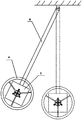
- Figure 3 is a front view of the connection of the present invention applied to a simple pendulum model
- Figure 4 is a side view of the connection used in the single pendulum model of the present invention.
- Figure 5 is a schematic diagram of the state of use of the present invention in the inverted pendulum
- the above drawings include the following reference signs: 1. Housing; 2. Partition; 3. Drive assembly; 31. Encoder; 32. Drive; 33. Transmission; 4. Moment of inertia disc; 5. Output shaft ; 6. Controlled structure; 7. Flange bracket; 8. Flange plate.
- the active moment of inertia drive control system of the present invention includes an output carrier, a drive assembly 3 and a moment of inertia disk 4;
- the output carrier includes a partition plate 2 and a housing 1.
- the partition plate is fixed on the inner wall of the housing, and the housing is connected to the controlled structure 6; the controlled structure is equipped with a sensor, the sensor is a photoelectric shaft angle encoder, angular acceleration
- the sensor or gyroscope is used to collect the state data of the controlled structure. The sensor needs to ensure that it can collect the swing angle and the swing angular acceleration data of the system's gyration vibration.
- the sensor to detect the state of the controlled structure can be a photoelectric encoder, which is arranged at the hanging point to collect the pendulum structure's swing angle and pendulum angular acceleration data.
- One end of the drive assembly is fixed on the housing, and the other end is fixed on the partition.
- the end of the drive assembly is connected to the output shaft 5, which extends out of the housing and is connected to the moment of inertia disk;
- the drive assembly includes a driver 32 and a transmission 33 and encoder 31, what the present invention requires is not a high speed output but a force output, so the transmission adopts a reducer to reduce the speed to meet the force output.
- the output end of the driver is connected with the transmission, the transmission is externally connected with the output shaft, the driver, the transmission and the encoder are coaxially connected, and the driver and the transmission have the same contour;
- the driver is a stepper motor or a servo motor, and the drive assembly passes through a flange bracket 7 Fixed on the shell and the partition, the output shaft is connected with the moment of inertia disk through the flange plate 8.
- the moment of inertia disc is a disc or ring with a certain mass; the material is usually a metal material or other materials with higher density.
- the moment of inertia disc is parallel to the rotating surface of the controlled structure, and the drive assembly is connected perpendicularly to the moment of inertia disc.
- the present invention also includes a controller.
- the controller is connected to the encoder, sensor and driver circuit on the driver, receives signals from the encoder connected to the driver and the sensor connected to the controlled structure, and transmits control signals to the driver to control the driver pair
- the driving direction and rotation speed, control and transmission of the rotational inertia disc are in the prior art, which involves simple signal transmission and processing functions, and will not be repeated here.
- the force of the system is generated by the rotation of the rotational inertia disk driven by the drive assembly.
- the main partition is transmitted to the shell and acts on the controlled structure.
- the force passes through the drive assembly.
- the components are transferred to the shell and then act on the controlled structure.
- the invention can also be connected to the inverted pendulum to control the swing of the inverted pendulum.
- the sensor collects the oscillating motion state of the controlled structure, that is, the oscillating angle and the oscillating angular acceleration data, and transmits the structure state data to the controller.
- the controller determines whether active control is required. When the structure rotates and the oscillating motion data exceeds the previous setting When the threshold is set, the controller controls the drive to move, and the drive assembly starts to move.
- the drive can control the rotation of the moment of inertia disk according to the real-time measured structure motion state, and the reaction force generated by the rotation of the moment of inertia disk acts on the shell. Furthermore, it is transmitted to the controlled structure connected with the casing to restrain the swing of the controlled structure.
- An encoder is installed coaxially at the end of the drive, which collects the rotation of the drive in real time and feeds it back to the controller to realize the closed-loop control device of the controller, the controlled structure and the drive.
- the drive can be changed in real time
- the rotation of the controlled moment of inertia disc adjusts the control torque acting on the controlled structure, adjusts the size of the drive energy output, controls the vibration of the structure, and ensures higher control efficiency.
- the basic principle of the present invention comes from the basic concept of mechanics: force and force couple cannot be equivalent to each other. In some cases, the motion characteristics of the controlled object determine that the form of rotational motion must be controlled by torque. Therefore, traditional control devices that use force or linear motion will fail.
- the present invention proposes a suitable structure or system for rotation or torsion or rotation. Active control device for swing motion control.
- the application of the present invention is not limited to the shimmy (single pendulum) motion control of the suspension structure under the action of gravity; the flutter control and buffeting control of the long-span suspension bridge under the action of wind load; the wind and seismic vibration control of the civil engineering structure, the vehicle Pitch motion control under the excitation of road irregularities, roll, pitch and yaw motion control of ship or offshore platform structure under the combined excitation of wind, wave and current, and fixed-axis rotation motion control of rigid bodies around space axes.
Landscapes
- Engineering & Computer Science (AREA)
- Architecture (AREA)
- Business, Economics & Management (AREA)
- Emergency Management (AREA)
- Environmental & Geological Engineering (AREA)
- Civil Engineering (AREA)
- Structural Engineering (AREA)
- General Engineering & Computer Science (AREA)
- Mechanical Engineering (AREA)
- Vibration Prevention Devices (AREA)
- Buildings Adapted To Withstand Abnormal External Influences (AREA)
- Building Environments (AREA)
Abstract
Description
Claims (9)
- 一种主动转动惯量驱动控制系统,其特征在于,包括出力载体、驱动总成(3)以及转动惯量盘(4);出力载体包括隔板(2)以及壳体(1),隔板(2)固定在壳体(1)内壁上,壳体(1)连接在被控结构(6)上;驱动总成(3)一端固定在壳体(1)上,另一端固定在隔板(2)上,驱动总成(3)端部连接出力轴(5),出力轴(5)另一端伸出到壳体(1)外,与转动惯量盘(4)连接;转动惯量盘(4)为一定质量的圆盘或者圆环。
- 根据权利要求1所述的主动转动惯量驱动控制系统,其特征在于,驱动总成(3)包括驱动器(32)、变速器(33)以及编码器(31),驱动器(32)输出端与和变速器(33)连接,变速器(33)外连出力轴(5),驱动器(32)、变速器(33)以及编码器(31)同轴连接,驱动器(32)与变速器(33)外形轮廓相同。
- 根据权利要求2所述的主动转动惯量驱动控制系统,其特征在于,所述驱动器(32)为步进电机或者伺服电机。
- 根据权利要求1所述的主动转动惯量驱动控制系统,其特征在于,驱动总成(3)通过法兰支架(7)固定在壳体(1)和隔板(2)上。
- 根据权利要求1所述的主动转动惯量驱动控制系统,其特征在于,出力轴(5)通过法兰盘(8)与转动惯量盘(4)连接。
- 根据权利要求1所述的主动转动惯量驱动控制系统,其特征在于,所述转动惯量盘(4)平行于被控结构(6)旋转面,驱动总成(3)与转动惯量盘(4)垂直连接。
- 根据权利要求2所述的主动转动惯量驱动控制系统,其特征在于,被控结构(6)上安装有传感器,用于采集被控结构(6)的状态数据。
- 根据权利要求2所述的主动转动惯量驱动控制系统,其特征在于,变速器(33)为减速器。
- 根据权利要求7所述的主动转动惯量驱动控制系统,其特征在于,还包括控制器,控制器与编码器(31)、传感器以及驱动器(32)线路连接,接收编码器(31)以及传感器的信号,并传递控制信号给驱动器(32),控制驱动器(32)对转动惯量盘(4)的驱动方向以及转速。
Priority Applications (5)
| Application Number | Priority Date | Filing Date | Title |
|---|---|---|---|
| KR1020207023884A KR102259052B1 (ko) | 2019-02-01 | 2019-09-12 | 액티브 관성 모멘트 구동 제어 시스템 |
| EP19909621.5A EP3730713B1 (en) | 2019-02-01 | 2019-09-12 | Active rotational inertia drive control system |
| JP2020541745A JP6899492B2 (ja) | 2019-02-01 | 2019-09-12 | 能動回転慣性量駆動制御システム |
| CA3091739A CA3091739C (en) | 2019-02-01 | 2019-09-12 | Active rotary inertia driver system |
| US16/985,179 US10962076B2 (en) | 2019-02-01 | 2020-08-04 | Active rotary inertia driver system |
Applications Claiming Priority (2)
| Application Number | Priority Date | Filing Date | Title |
|---|---|---|---|
| CN201910103396.5 | 2019-02-01 | ||
| CN201910103396.5A CN109610673B (zh) | 2019-02-01 | 2019-02-01 | 主动转动惯量驱动控制系统 |
Related Child Applications (1)
| Application Number | Title | Priority Date | Filing Date |
|---|---|---|---|
| US16/985,179 Continuation US10962076B2 (en) | 2019-02-01 | 2020-08-04 | Active rotary inertia driver system |
Publications (1)
| Publication Number | Publication Date |
|---|---|
| WO2020155636A1 true WO2020155636A1 (zh) | 2020-08-06 |
Family
ID=66019492
Family Applications (1)
| Application Number | Title | Priority Date | Filing Date |
|---|---|---|---|
| PCT/CN2019/105646 Ceased WO2020155636A1 (zh) | 2019-02-01 | 2019-09-12 | 主动转动惯量驱动控制系统 |
Country Status (8)
| Country | Link |
|---|---|
| US (1) | US10962076B2 (zh) |
| EP (1) | EP3730713B1 (zh) |
| JP (1) | JP6899492B2 (zh) |
| KR (1) | KR102259052B1 (zh) |
| CN (1) | CN109610673B (zh) |
| AU (1) | AU2019101723A4 (zh) |
| CA (1) | CA3091739C (zh) |
| WO (1) | WO2020155636A1 (zh) |
Cited By (1)
| Publication number | Priority date | Publication date | Assignee | Title |
|---|---|---|---|---|
| CN113530339A (zh) * | 2020-10-26 | 2021-10-22 | 长江师范学院 | 一种用于建筑减震墙体施工的现浇装配结构 |
Families Citing this family (8)
| Publication number | Priority date | Publication date | Assignee | Title |
|---|---|---|---|---|
| CN109610673B (zh) * | 2019-02-01 | 2023-11-24 | 青岛理工大学 | 主动转动惯量驱动控制系统 |
| CN110761432B (zh) * | 2019-10-31 | 2021-04-20 | 青岛理工大学 | 转动惯量产生力矩控制方法 |
| CN110778641B (zh) * | 2019-10-31 | 2021-06-22 | 青岛理工大学 | 高速列车动态行为主动控制系统 |
| CN110641501B (zh) * | 2019-10-31 | 2021-08-13 | 青岛理工大学 | 高速列车侧滚、点头、摇头动态行为的力矩控制方法 |
| TWI766449B (zh) * | 2020-11-25 | 2022-06-01 | 國立臺灣科技大學 | 主動慣質阻尼器 |
| US12270449B2 (en) * | 2022-03-03 | 2025-04-08 | Ge Infrastructure Technology Llc | Automatically tunable mass damper |
| CN115233540B (zh) * | 2022-08-15 | 2024-09-24 | 沈阳工业大学 | 抑制桥梁多模态耦合振动的主被动混合控制系统 |
| CN116661312B (zh) * | 2023-05-26 | 2026-04-17 | 华中科技大学 | 一种主动和被动相结合的三级微振隔振系统及方法 |
Citations (5)
| Publication number | Priority date | Publication date | Assignee | Title |
|---|---|---|---|---|
| US5964327A (en) * | 1996-10-14 | 1999-10-12 | Hawse Company Limited | Active control apparatus and method for vibration reduction |
| CN102825613A (zh) * | 2012-09-17 | 2012-12-19 | 北京航空航天大学 | 一种基于可控局部自由度的主动减振方法与装置 |
| CN107022955A (zh) * | 2017-02-27 | 2017-08-08 | 华北水利水电大学 | 表观质量旋转式电磁阻尼器斜拉索减振装置及设计方法 |
| CN109610673A (zh) * | 2019-02-01 | 2019-04-12 | 青岛理工大学 | 主动转动惯量驱动控制系统 |
| CN209509216U (zh) * | 2019-02-01 | 2019-10-18 | 青岛理工大学 | 主动转动惯量驱动控制系统 |
Family Cites Families (19)
| Publication number | Priority date | Publication date | Assignee | Title |
|---|---|---|---|---|
| US3548972A (en) * | 1969-03-18 | 1970-12-22 | Kaman Aerospace Corp | Vibration absorber with rotating mass |
| JP2668990B2 (ja) * | 1988-10-06 | 1997-10-27 | 石川島播磨重工業株式会社 | 構造物制振装置 |
| JPH05240294A (ja) * | 1992-02-25 | 1993-09-17 | Ishikawajima Harima Heavy Ind Co Ltd | 動吸振機 |
| US5542220A (en) * | 1993-11-30 | 1996-08-06 | Mitsubishi Jukogyo Kabushiki Kaisha | Hydrostatic anti-vibration system and adjusting method therefor |
| JP2000088045A (ja) * | 1998-09-16 | 2000-03-28 | Honda Motor Co Ltd | ダイナミックダンパ装置 |
| CN100582410C (zh) * | 2007-01-22 | 2010-01-20 | 哈尔滨工业大学 | 结构振动控制的新型混合质量驱动变阻尼控制装置 |
| US8672107B2 (en) * | 2010-03-11 | 2014-03-18 | The United States Of America As Represented By The Administrator Of The National Aeronautics And Space Administration | Compact vibration damper |
| CN101812879B (zh) * | 2010-03-26 | 2012-07-25 | 北京工业大学 | 控制建筑结构三维平动及水平扭转的调谐质量阻尼器及其制作方法 |
| CN202265916U (zh) * | 2011-09-07 | 2012-06-06 | 江苏金风风电设备制造有限公司 | 调谐质量阻尼器减振控制装置 |
| DE102012222191A1 (de) * | 2012-12-04 | 2014-06-05 | Wobben Properties Gmbh | Schwingungsbegrenzungs-Modul sowie Vorrichtung, Bausegment für eine Baueinrichtung und Windenergieanlage mit einem Schwingungsbegrenzungs-Modul |
| CN102995787B (zh) * | 2012-12-26 | 2015-07-08 | 清华大学 | 滚动质量调谐阻尼器 |
| CN103277454B (zh) * | 2013-05-09 | 2016-05-18 | 张春巍 | 调谐转动惯量阻尼减振装置 |
| US9624998B2 (en) * | 2014-07-30 | 2017-04-18 | Tenneco Automotive Operating Company Inc. | Electromagnetic flywheel damper and method therefor |
| DK3341627T3 (da) * | 2015-08-28 | 2020-01-06 | Fm Energie Gmbh & Co Kg | Svingningsdæmper med roterende masse |
| CN105926796B (zh) * | 2016-06-21 | 2017-10-27 | 山东大学 | 压电阻尼智能调谐减振控制装置 |
| US10914357B2 (en) * | 2017-02-15 | 2021-02-09 | Amir Khajepour | Multi-axis reaction system and method for vibration control of mechanical systems |
| CN108964342B (zh) * | 2018-06-22 | 2020-07-14 | 河海大学 | 一种可在线连续控制惯容量的半主动惯容 |
| CN109084882B (zh) * | 2018-09-30 | 2023-09-26 | 华南理工大学 | 旋转圆盘振动检测控制装置及方法 |
| CN109654162B (zh) * | 2019-02-01 | 2024-04-12 | 青岛理工大学 | 主动复合变阻尼转动控制装置 |
-
2019
- 2019-02-01 CN CN201910103396.5A patent/CN109610673B/zh not_active Expired - Fee Related
- 2019-09-12 AU AU2019101723A patent/AU2019101723A4/en not_active Ceased
- 2019-09-12 WO PCT/CN2019/105646 patent/WO2020155636A1/zh not_active Ceased
- 2019-09-12 JP JP2020541745A patent/JP6899492B2/ja not_active Expired - Fee Related
- 2019-09-12 KR KR1020207023884A patent/KR102259052B1/ko not_active Expired - Fee Related
- 2019-09-12 CA CA3091739A patent/CA3091739C/en active Active
- 2019-09-12 EP EP19909621.5A patent/EP3730713B1/en not_active Not-in-force
-
2020
- 2020-08-04 US US16/985,179 patent/US10962076B2/en active Active
Patent Citations (5)
| Publication number | Priority date | Publication date | Assignee | Title |
|---|---|---|---|---|
| US5964327A (en) * | 1996-10-14 | 1999-10-12 | Hawse Company Limited | Active control apparatus and method for vibration reduction |
| CN102825613A (zh) * | 2012-09-17 | 2012-12-19 | 北京航空航天大学 | 一种基于可控局部自由度的主动减振方法与装置 |
| CN107022955A (zh) * | 2017-02-27 | 2017-08-08 | 华北水利水电大学 | 表观质量旋转式电磁阻尼器斜拉索减振装置及设计方法 |
| CN109610673A (zh) * | 2019-02-01 | 2019-04-12 | 青岛理工大学 | 主动转动惯量驱动控制系统 |
| CN209509216U (zh) * | 2019-02-01 | 2019-10-18 | 青岛理工大学 | 主动转动惯量驱动控制系统 |
Non-Patent Citations (1)
| Title |
|---|
| See also references of EP3730713A4 * |
Cited By (1)
| Publication number | Priority date | Publication date | Assignee | Title |
|---|---|---|---|---|
| CN113530339A (zh) * | 2020-10-26 | 2021-10-22 | 长江师范学院 | 一种用于建筑减震墙体施工的现浇装配结构 |
Also Published As
| Publication number | Publication date |
|---|---|
| US10962076B2 (en) | 2021-03-30 |
| CA3091739C (en) | 2023-01-10 |
| CN109610673A (zh) | 2019-04-12 |
| AU2019101723A4 (en) | 2020-04-02 |
| KR20200103116A (ko) | 2020-09-01 |
| CA3091739A1 (en) | 2020-08-06 |
| EP3730713A1 (en) | 2020-10-28 |
| JP2021509701A (ja) | 2021-04-01 |
| EP3730713A4 (en) | 2021-10-27 |
| US20200362932A1 (en) | 2020-11-19 |
| EP3730713B1 (en) | 2022-05-04 |
| KR102259052B1 (ko) | 2021-05-31 |
| CN109610673B (zh) | 2023-11-24 |
| JP6899492B2 (ja) | 2021-07-07 |
Similar Documents
| Publication | Publication Date | Title |
|---|---|---|
| WO2020155636A1 (zh) | 主动转动惯量驱动控制系统 | |
| AU2019101722A4 (en) | Hybrid control system for suppressing flutter vibration of bridge structure | |
| CN109610672B (zh) | 悬吊式复合调谐转动惯量驱动控制系统 | |
| US10889982B2 (en) | Translation-rotation hybrid vibration control system for buildings | |
| CN209509214U (zh) | 带阻尼液箱的转动惯量主动控制装置 | |
| AU2019101724A4 (en) | Active hybrid rotational control system with variable damping functions | |
| WO2020155643A1 (zh) | 自供能式主被动复合转动惯量驱动控制系统 | |
| WO2020155644A1 (zh) | 自适应机械驱动调节转动惯量式控制系统 | |
| CN110761432B (zh) | 转动惯量产生力矩控制方法 | |
| CN209508798U (zh) | 复合式桥梁扭转振动控制系统 | |
| CN209509216U (zh) | 主动转动惯量驱动控制系统 | |
| CN109667357B (zh) | 带阻尼液箱的转动惯量主动控制装置 | |
| CN209509217U (zh) | 平转复合式建筑振动控制系统 | |
| WO2020155640A1 (zh) | 电磁变阻尼旋转控制系统 | |
| CN108412069B (zh) | 超长周期tmd控制系统 | |
| WO2020155639A1 (zh) | 自走式全方向转动惯量驱动控制系统 | |
| CN209509219U (zh) | 悬吊式复合调谐转动惯量驱动控制系统 | |
| CN209511004U (zh) | 主动复合变阻尼转动控制装置 | |
| CN209568566U (zh) | 自走式全方向转动惯量驱动控制系统 | |
| CN209511005U (zh) | 自供能式主被动复合转动惯量驱动控制系统 | |
| CN115875578A (zh) | 一种中央斗屏减震平台 |
Legal Events
| Date | Code | Title | Description |
|---|---|---|---|
| ENP | Entry into the national phase |
Ref document number: 2020541745 Country of ref document: JP Kind code of ref document: A |
|
| ENP | Entry into the national phase |
Ref document number: 2019909621 Country of ref document: EP Effective date: 20200721 |
|
| ENP | Entry into the national phase |
Ref document number: 20207023884 Country of ref document: KR Kind code of ref document: A Ref document number: 3091739 Country of ref document: CA |
|
| 121 | Ep: the epo has been informed by wipo that ep was designated in this application |
Ref document number: 19909621 Country of ref document: EP Kind code of ref document: A1 |
|
| NENP | Non-entry into the national phase |
Ref country code: DE |