WO2020156455A1 - 车灯照明模组、车灯及车辆 - Google Patents
车灯照明模组、车灯及车辆 Download PDFInfo
- Publication number
- WO2020156455A1 WO2020156455A1 PCT/CN2020/073848 CN2020073848W WO2020156455A1 WO 2020156455 A1 WO2020156455 A1 WO 2020156455A1 CN 2020073848 W CN2020073848 W CN 2020073848W WO 2020156455 A1 WO2020156455 A1 WO 2020156455A1
- Authority
- WO
- WIPO (PCT)
- Prior art keywords
- light
- optical element
- low
- primary optical
- vehicle lamp
- Prior art date
- Legal status (The legal status is an assumption and is not a legal conclusion. Google has not performed a legal analysis and makes no representation as to the accuracy of the status listed.)
- Ceased
Links
Images


Classifications
-
- F—MECHANICAL ENGINEERING; LIGHTING; HEATING; WEAPONS; BLASTING
- F21—LIGHTING
- F21S—NON-PORTABLE LIGHTING DEVICES; SYSTEMS THEREOF; VEHICLE LIGHTING DEVICES SPECIALLY ADAPTED FOR VEHICLE EXTERIORS
- F21S41/00—Illuminating devices specially adapted for vehicle exteriors, e.g. headlamps
- F21S41/10—Illuminating devices specially adapted for vehicle exteriors, e.g. headlamps characterised by the light source
- F21S41/14—Illuminating devices specially adapted for vehicle exteriors, e.g. headlamps characterised by the light source characterised by the type of light source
- F21S41/141—Light emitting diodes [LED]
- F21S41/143—Light emitting diodes [LED] the main emission direction of the LED being parallel to the optical axis of the illuminating device
-
- F—MECHANICAL ENGINEERING; LIGHTING; HEATING; WEAPONS; BLASTING
- F21—LIGHTING
- F21S—NON-PORTABLE LIGHTING DEVICES; SYSTEMS THEREOF; VEHICLE LIGHTING DEVICES SPECIALLY ADAPTED FOR VEHICLE EXTERIORS
- F21S41/00—Illuminating devices specially adapted for vehicle exteriors, e.g. headlamps
- F21S41/10—Illuminating devices specially adapted for vehicle exteriors, e.g. headlamps characterised by the light source
- F21S41/14—Illuminating devices specially adapted for vehicle exteriors, e.g. headlamps characterised by the light source characterised by the type of light source
- F21S41/141—Light emitting diodes [LED]
- F21S41/147—Light emitting diodes [LED] the main emission direction of the LED being angled to the optical axis of the illuminating device
-
- F—MECHANICAL ENGINEERING; LIGHTING; HEATING; WEAPONS; BLASTING
- F21—LIGHTING
- F21S—NON-PORTABLE LIGHTING DEVICES; SYSTEMS THEREOF; VEHICLE LIGHTING DEVICES SPECIALLY ADAPTED FOR VEHICLE EXTERIORS
- F21S41/00—Illuminating devices specially adapted for vehicle exteriors, e.g. headlamps
- F21S41/10—Illuminating devices specially adapted for vehicle exteriors, e.g. headlamps characterised by the light source
- F21S41/14—Illuminating devices specially adapted for vehicle exteriors, e.g. headlamps characterised by the light source characterised by the type of light source
- F21S41/141—Light emitting diodes [LED]
- F21S41/151—Light emitting diodes [LED] arranged in one or more lines
-
- F—MECHANICAL ENGINEERING; LIGHTING; HEATING; WEAPONS; BLASTING
- F21—LIGHTING
- F21S—NON-PORTABLE LIGHTING DEVICES; SYSTEMS THEREOF; VEHICLE LIGHTING DEVICES SPECIALLY ADAPTED FOR VEHICLE EXTERIORS
- F21S41/00—Illuminating devices specially adapted for vehicle exteriors, e.g. headlamps
- F21S41/20—Illuminating devices specially adapted for vehicle exteriors, e.g. headlamps characterised by refractors, transparent cover plates, light guides or filters
- F21S41/24—Light guides
-
- F—MECHANICAL ENGINEERING; LIGHTING; HEATING; WEAPONS; BLASTING
- F21—LIGHTING
- F21S—NON-PORTABLE LIGHTING DEVICES; SYSTEMS THEREOF; VEHICLE LIGHTING DEVICES SPECIALLY ADAPTED FOR VEHICLE EXTERIORS
- F21S41/00—Illuminating devices specially adapted for vehicle exteriors, e.g. headlamps
- F21S41/20—Illuminating devices specially adapted for vehicle exteriors, e.g. headlamps characterised by refractors, transparent cover plates, light guides or filters
- F21S41/25—Projection lenses
- F21S41/255—Lenses with a front view of circular or truncated circular outline
-
- F—MECHANICAL ENGINEERING; LIGHTING; HEATING; WEAPONS; BLASTING
- F21—LIGHTING
- F21S—NON-PORTABLE LIGHTING DEVICES; SYSTEMS THEREOF; VEHICLE LIGHTING DEVICES SPECIALLY ADAPTED FOR VEHICLE EXTERIORS
- F21S41/00—Illuminating devices specially adapted for vehicle exteriors, e.g. headlamps
- F21S41/20—Illuminating devices specially adapted for vehicle exteriors, e.g. headlamps characterised by refractors, transparent cover plates, light guides or filters
- F21S41/25—Projection lenses
- F21S41/275—Lens surfaces, e.g. coatings or surface structures
-
- F—MECHANICAL ENGINEERING; LIGHTING; HEATING; WEAPONS; BLASTING
- F21—LIGHTING
- F21S—NON-PORTABLE LIGHTING DEVICES; SYSTEMS THEREOF; VEHICLE LIGHTING DEVICES SPECIALLY ADAPTED FOR VEHICLE EXTERIORS
- F21S41/00—Illuminating devices specially adapted for vehicle exteriors, e.g. headlamps
- F21S41/20—Illuminating devices specially adapted for vehicle exteriors, e.g. headlamps characterised by refractors, transparent cover plates, light guides or filters
- F21S41/29—Attachment thereof
-
- F—MECHANICAL ENGINEERING; LIGHTING; HEATING; WEAPONS; BLASTING
- F21—LIGHTING
- F21S—NON-PORTABLE LIGHTING DEVICES; SYSTEMS THEREOF; VEHICLE LIGHTING DEVICES SPECIALLY ADAPTED FOR VEHICLE EXTERIORS
- F21S41/00—Illuminating devices specially adapted for vehicle exteriors, e.g. headlamps
- F21S41/30—Illuminating devices specially adapted for vehicle exteriors, e.g. headlamps characterised by reflectors
- F21S41/32—Optical layout thereof
- F21S41/322—Optical layout thereof the reflector using total internal reflection
-
- F—MECHANICAL ENGINEERING; LIGHTING; HEATING; WEAPONS; BLASTING
- F21—LIGHTING
- F21S—NON-PORTABLE LIGHTING DEVICES; SYSTEMS THEREOF; VEHICLE LIGHTING DEVICES SPECIALLY ADAPTED FOR VEHICLE EXTERIORS
- F21S41/00—Illuminating devices specially adapted for vehicle exteriors, e.g. headlamps
- F21S41/40—Illuminating devices specially adapted for vehicle exteriors, e.g. headlamps characterised by screens, non-reflecting members, light-shielding members or fixed shades
- F21S41/43—Illuminating devices specially adapted for vehicle exteriors, e.g. headlamps characterised by screens, non-reflecting members, light-shielding members or fixed shades characterised by the shape thereof
-
- F—MECHANICAL ENGINEERING; LIGHTING; HEATING; WEAPONS; BLASTING
- F21—LIGHTING
- F21S—NON-PORTABLE LIGHTING DEVICES; SYSTEMS THEREOF; VEHICLE LIGHTING DEVICES SPECIALLY ADAPTED FOR VEHICLE EXTERIORS
- F21S41/00—Illuminating devices specially adapted for vehicle exteriors, e.g. headlamps
- F21S41/60—Illuminating devices specially adapted for vehicle exteriors, e.g. headlamps characterised by a variable light distribution
- F21S41/65—Illuminating devices specially adapted for vehicle exteriors, e.g. headlamps characterised by a variable light distribution by acting on light sources
- F21S41/663—Illuminating devices specially adapted for vehicle exteriors, e.g. headlamps characterised by a variable light distribution by acting on light sources by switching light sources
-
- F—MECHANICAL ENGINEERING; LIGHTING; HEATING; WEAPONS; BLASTING
- F21—LIGHTING
- F21S—NON-PORTABLE LIGHTING DEVICES; SYSTEMS THEREOF; VEHICLE LIGHTING DEVICES SPECIALLY ADAPTED FOR VEHICLE EXTERIORS
- F21S45/00—Arrangements within vehicle lighting devices specially adapted for vehicle exteriors, for purposes other than emission or distribution of light
- F21S45/40—Cooling of lighting devices
- F21S45/47—Passive cooling, e.g. using fins, thermal conductive elements or openings
-
- F—MECHANICAL ENGINEERING; LIGHTING; HEATING; WEAPONS; BLASTING
- F21—LIGHTING
- F21V—FUNCTIONAL FEATURES OR DETAILS OF LIGHTING DEVICES OR SYSTEMS THEREOF; STRUCTURAL COMBINATIONS OF LIGHTING DEVICES WITH OTHER ARTICLES, NOT OTHERWISE PROVIDED FOR
- F21V17/00—Fastening of component parts of lighting devices, e.g. shades, globes, refractors, reflectors, filters, screens, grids or protective cages
- F21V17/10—Fastening of component parts of lighting devices, e.g. shades, globes, refractors, reflectors, filters, screens, grids or protective cages characterised by specific fastening means or way of fastening
-
- F—MECHANICAL ENGINEERING; LIGHTING; HEATING; WEAPONS; BLASTING
- F21—LIGHTING
- F21V—FUNCTIONAL FEATURES OR DETAILS OF LIGHTING DEVICES OR SYSTEMS THEREOF; STRUCTURAL COMBINATIONS OF LIGHTING DEVICES WITH OTHER ARTICLES, NOT OTHERWISE PROVIDED FOR
- F21V29/00—Protecting lighting devices from thermal damage; Cooling or heating arrangements specially adapted for lighting devices or systems
- F21V29/50—Cooling arrangements
- F21V29/502—Cooling arrangements characterised by the adaptation for cooling of specific components
- F21V29/504—Cooling arrangements characterised by the adaptation for cooling of specific components of refractors
-
- F—MECHANICAL ENGINEERING; LIGHTING; HEATING; WEAPONS; BLASTING
- F21—LIGHTING
- F21S—NON-PORTABLE LIGHTING DEVICES; SYSTEMS THEREOF; VEHICLE LIGHTING DEVICES SPECIALLY ADAPTED FOR VEHICLE EXTERIORS
- F21S41/00—Illuminating devices specially adapted for vehicle exteriors, e.g. headlamps
- F21S41/20—Illuminating devices specially adapted for vehicle exteriors, e.g. headlamps characterised by refractors, transparent cover plates, light guides or filters
- F21S41/285—Refractors, transparent cover plates, light guides or filters not provided in groups F21S41/24 - F21S41/2805
-
- F—MECHANICAL ENGINEERING; LIGHTING; HEATING; WEAPONS; BLASTING
- F21—LIGHTING
- F21W—INDEXING SCHEME ASSOCIATED WITH SUBCLASSES F21K, F21L, F21S and F21V, RELATING TO USES OR APPLICATIONS OF LIGHTING DEVICES OR SYSTEMS
- F21W2102/00—Exterior vehicle lighting devices for illuminating purposes
- F21W2102/10—Arrangement or contour of the emitted light
- F21W2102/13—Arrangement or contour of the emitted light for high-beam region or low-beam region
-
- F—MECHANICAL ENGINEERING; LIGHTING; HEATING; WEAPONS; BLASTING
- F21—LIGHTING
- F21W—INDEXING SCHEME ASSOCIATED WITH SUBCLASSES F21K, F21L, F21S and F21V, RELATING TO USES OR APPLICATIONS OF LIGHTING DEVICES OR SYSTEMS
- F21W2102/00—Exterior vehicle lighting devices for illuminating purposes
- F21W2102/10—Arrangement or contour of the emitted light
- F21W2102/17—Arrangement or contour of the emitted light for regions other than high beam or low beam
- F21W2102/18—Arrangement or contour of the emitted light for regions other than high beam or low beam for overhead signs
Definitions
- the invention relates to a vehicle lamp lighting device, in particular to a vehicle lamp lighting module, and in addition, to a vehicle lamp and a vehicle.
- High-beam light is a commonly used lighting tool in the process of driving. It is generally necessary to use high-beam when driving in open or low-light places such as high-speed or suburban areas. However, when there is a vehicle on the opposite side and need to meet, you need to switch to Low beam headlights, and low beam headlights are generally used when driving on urban roads to prevent the high beam headlights from affecting the sight of drivers of on-going vehicles and pedestrians on the road and causing safety hazards.
- automobile headlights mostly use light-emitting modules that integrate far and near beams, which are mainly arranged by superimposing the low-beam condenser and the high-beam condenser. Since as many as dozens of light sources are integrated together, the light shapes between them must be independent Can’t interfere with each other.
- the low-beam condenser or the high-beam condenser needs to be very delicate and compact. A small tolerance can have a great impact on the result of the light shape. It requires high tolerances for optical components and requires high assembly accuracy. Very high.
- the technical problem to be solved by the present invention is to provide a vehicle lamp lighting module, which has more precise light shape control, accurate assembly and high light energy utilization rate.
- the technical problem to be solved by the present invention is to provide a vehicle lamp which has a high light energy utilization rate, a compact structure and stable optical performance.
- the technical problem to be solved by the present invention is to provide a vehicle which has a high utilization rate of light energy, a compact structure and stable optical performance.
- the first aspect of the present invention provides a vehicle lamp lighting module, including a light source, a low beam primary optical element, a high beam primary optical element and a secondary optical element, the low beam primary optical element is arranged as It can guide light to exit through the low-beam primary optical element and the secondary optical element in order to form a low-beam light shape.
- the high-beam primary optical element includes a plurality of collimating units, and the end faces of the light emitting ends of the collimating units are mutually Connected or integrally formed as a high-beam light-emitting surface, and the light-incoming end of each collimating unit corresponds to the light source in a one-to-one correspondence, so that light can be emitted through the high-beam primary optical element and the secondary optical element in sequence Form a high beam light shape.
- the low-beam primary optical element includes a low-beam entrance surface, a low-beam light guide portion, and a low-beam exit surface, and the low-beam light guide portion is arranged to be able to guide the light emission received by the low-beam entrance surface.
- a reflecting portion is formed on the lower surface of the low-beam light-emitting surface, and the low-beam light-incident surface is provided with a plurality of light-concentrating structures arranged one-to-one corresponding to the light source.
- the low-beam primary optical element is formed with a low-beam cutoff portion for forming a low-beam cutoff line.
- the low-beam primary optical element includes a first light channel and a second light channel, and there is an obliquely arranged reflective surface between the first light channel and the second light channel, so that light can pass from the first light channel to the second light channel.
- a light channel is reflected into the second light channel and emitted from the low-beam light exit surface at the front end of the second light channel.
- a plurality of light-incident surfaces of the first light channel are arranged in sequence.
- the light condensing structure is arranged in one-to-one correspondence with the light source, and the second light channel is provided with a low-beam cutoff portion for forming a low-beam cutoff line.
- the low-beam primary optical element includes a plurality of light-concentrating structures and reflecting parts, each of the light-concentrating structures is arranged in sequence along the rear edge of the reflecting part, and is arranged in a one-to-one correspondence with the light source.
- the front end of the portion is formed with a low-beam cutoff portion for forming a low-beam cutoff line, and the reflection portion has a plate-shaped structure.
- the distance between the front end of the reflecting part and the upper boundary of the front end of the high beam primary optical element is not more than 2 mm.
- the low beam exit surface is a concave curved surface adapted to the focal plane of the secondary optical element.
- the size of the light-concentrating structure located in the middle area is larger than the size of the other light-concentrating structures located in the two side areas.
- the lower edge of the low beam exit surface of the low beam primary optical element is connected to the edge of the high beam exit surface of the high beam primary optical element, and the low beam primary optical element is connected to the high beam primary optical element
- a wedge-shaped gap is formed with the gap gradually increasing from front to back.
- the condensing structure is a condensing cup structure with a cavity, and a curved surface convex toward the light source is provided in the cavity, or the light incident part of the concentrating structure is a flat surface, a convex curved surface, or an inner surface.
- Condenser cup structure with concave surface is a condensing cup structure with a cavity, and a curved surface convex toward the light source is provided in the cavity, or the light incident part of the concentrating structure is a flat surface, a convex curved surface, or an inner surface.
- each collimating unit is connected to each other or integrally formed with a high-beam cutoff portion for forming a high-beam cutoff line.
- the collimating unit includes the light entrance end, the light passing part, and the light exit end, and the light passing part of the collimating unit located in the middle part of the high-beam primary optical element is connected up and down with There are two light-incident ends, and the two light-incident ends are arranged to enable light to enter the corresponding light-passing portion.
- the high-beam primary optical element is connected to the heat sink through a limiting structure.
- the adjacent collimating units form an angle that gradually decreases from the back to the front gap, and the adjacent collimating units are connected by connecting ribs.
- the limiting structure includes a pressing plate and a support frame, and the support frame is provided with a limiting member that can be inserted into the gap between the corresponding adjacent collimating units, and the pressing plate and the support frame pass through the connecting structure.
- the high beam primary optical element is defined between the two.
- both the pressing plate and the support frame are provided with protrusions that conflict with the surface of the high beam primary optical element.
- the left and right ends of the support frame are respectively provided with limiting protrusions for limiting the left and right movement of the high beam primary optical element.
- the connecting ribs between the adjacent collimating units are clamped between the two limiting members.
- the limiting member is a truncated cone structure or a truncated pyramid structure with an upper cross-sectional area smaller than a lower cross-sectional area, and is adapted to the cross-sectional shape of the gap between the corresponding adjacent collimating units.
- connection structure includes a first buckle connected at both ends of the pressure plate and a bayonet on the support frame that cooperates with the first buckle.
- each collimating unit abuts against the positioning surface of the front of the support frame
- the lower surface of each collimating unit abuts against the positioning surface of the rear of the support frame
- the front of the pressure plate The positioning surface abuts against the upper surface of the front of each collimating unit, and the positioning surface at the rear of the pressing plate abuts against the upper surface of the rear of each collimating unit, so as to limit the vertical direction of the high beam primary optical element Degrees of freedom.
- connection structure includes a positioning hole formed on one of the pressure plate and the support frame, a positioning pin formed on the other, and a through hole for threaded connection on both.
- the light output ends of the collimating units are connected to each other or the lower end of the integrally formed structure is extended with flanged protrusions, and the flanged protrusions are buckled with the mounting grooves on the support frame.
- the low-beam primary optical element also includes a plurality of collimating units, and the light incident end of each collimating unit corresponds to the light source in a one-to-one correspondence.
- the light-emitting ends of the units are connected to each other or integrally formed as a low-beam light-emitting surface, and the light-emitting ends of each of the collimating units of the high-beam primary optical element are connected with each other or are integrally formed as a high-beam light-emitting surface, and heat dissipation is achieved through a limiting structure
- the limit structure includes a mounting bracket, an upper limit member and a lower limit member.
- the upper side of the mounting bracket is sequentially installed with the low-beam primary optical element and the upper and lower sides of the low-beam primary optical element from bottom to top.
- the upper limit member for limiting the direction, the lower side of the mounting bracket sequentially installs the high beam primary optical element and the lower limit member for limiting the upper and lower direction of the high beam primary optical element, the installation Both the upper and lower sides of the bracket are formed with a horizontal limiting structure for limiting the horizontal direction of the low beam primary optical element and the high beam primary optical element.
- the bottom of the upper limit member is provided with a plurality of upper limit bosses that form partial contact with the low-beam primary optical element
- the top of the lower limit member is provided with a plurality of upper-limit bosses that locally contact the high-beam primary optical element.
- the upper limit part and the lower limit part are bolted to the mounting bracket respectively, and the low beam primary optical element and the high beam primary optical element are both provided with second buckles, so Both upper and lower sides of the mounting bracket are provided with a clamping structure that cooperates with the second buckle.
- each of the horizontal limiting structures includes two rows of limiting posts, each of the limiting posts is inserted into the gap between the corresponding adjacent collimating units, and the adjacent collimating units The connecting ribs between are located between adjacent two of the two rows of limit posts.
- the high beam exit surface of the high beam primary optical element is a concave curved surface adapted to the focal plane of the secondary optical element or a curved surface gradually curved to the rear side from top to bottom.
- the included angle is 0°-5°.
- the light entrance end of the collimating unit is a condenser cup structure with a cavity, and the cavity is provided with a curved surface convex toward the light source, or a flat surface, a convex curved surface, or a concave curved surface.
- Condenser cup structure is a condenser cup structure with a cavity, and the cavity is provided with a curved surface convex toward the light source, or a flat surface, a convex curved surface, or a concave curved surface.
- the low beam primary optical element and the high beam primary optical element are transparent optical elements.
- the minimum distance between the focal point of the low beam primary optical element and the high beam primary optical element and the secondary optical element is ⁇ 2 mm.
- the light-emitting surface of the secondary optical element is provided or integrally formed with a grid structure.
- the single grid unit in the grid-like structure is a convex curved surface, a concave curved surface or a flat surface.
- the shape of a single grid unit in the grid-like structure is a rectangle, a square, a triangle, or a polygon.
- the light incident surface of the secondary optical element is provided with a low beam III region forming structure for forming a III region light shape.
- the low beam III region forming structure includes a plurality of longitudinal strip-shaped protrusions extending along the up-down direction of the secondary optical element; or the low beam III region forming structure includes A plurality of horizontal strip-shaped protrusions extending in the left-right direction of the element; or the formation structure of the low beam III region includes a plurality of block-shaped protrusions formed by connecting convex surfaces.
- each of the longitudinal strip-shaped protrusions is arranged obliquely from top to bottom toward the light emitting direction.
- the outer edge of the cross section of each of the longitudinal strip-shaped protrusions is a convex curve in which the central area is higher than the areas on both sides, and the outer edge of the longitudinal cross-section of each of the horizontal strip-shaped protrusions is the central area higher than the two sides.
- the convex curve of the area is a convex curve in which the central area is higher than the areas on both sides, and the outer edge of the longitudinal cross-section of each of the horizontal strip-shaped protrusions is the central area higher than the two sides.
- each longitudinal strip-shaped protrusion is equal, and the width of each horizontal strip-shaped protrusion is equal.
- the central area of each of the block-shaped protrusions is higher than the surrounding area.
- the light incident surface of the secondary optical element is a flat surface or a convex curved surface.
- the upper and middle areas of the light incident surface of the secondary optical element are planes along the up and down direction, and the lower area is a plane inclined from top to bottom to the light emission direction, and the low beam III zone forming structure is located The lower area.
- the low beam III region forming structure includes a section of convex structure connected by a plurality of longitudinal strip-shaped protrusions arranged on the light incident surface of the secondary optical element, or the near beam
- the light III region forming structure includes a plurality of the longitudinal strip-shaped protrusions sequentially arranged from the left edge to the right edge of the light incident surface of the secondary optical element.
- the width of the transverse cross section of the convex structure gradually decreases from the middle to the two sides.
- a vehicle lamp comprising the vehicle lamp lighting module described in the above technical solution, a radiator and a lens mounting bracket, the secondary optical element is a lens, and the secondary optical element passes through the lens
- the mounting bracket is connected with the radiator, and the vehicle lamp lighting module is mounted on the radiator and located in the cavity enclosed by the radiator and the lens mounting bracket.
- a third aspect of the present invention provides a vehicle including the vehicle lamp described in the above technical solution.
- the present invention can realize the integrated design of far and near beams by arranging the low beam primary optical element and the high beam primary optical element at the same time.
- the light propagates inside the low beam primary optical element and the high beam primary optical element, and the light energy
- the utilization efficiency is high; moreover, the design of combining multiple collimating units to form the primary optical element of the high beam makes the light shape corresponding to each light source independent and does not interfere with each other, so as to control the light shape more accurately and realize the prevention High beam dazzling function.
- the low-beam region III formation structure is usually arranged below the low-beam primary optical element. Since the front ends of the low-beam primary optical element and the high-beam primary optical element are connected up and down, the formation of the low-beam region III The light of the structure cannot reach the secondary optical element and is projected to the low-beam zone III light-shaped area.
- the present invention creatively arranges the low-beam zone III formation structure on the secondary optical element, so that the low-beam zone III light shape will not be affected. The influence of the positional relationship between the low beam primary optical element and the high beam primary optical element.
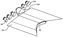
- FIG. 1 is one of the three-dimensional schematic diagrams of the vehicle lamp lighting module in the first specific embodiment of the present invention
- FIG 2 is the second three-dimensional structural diagram of the vehicle lamp lighting module in the first specific embodiment of the present invention.
- FIG. 3 is a schematic diagram of the rear view structure of the vehicle lamp lighting module in the first specific embodiment of the present invention.
- FIG. 4 is a schematic cross-sectional view of the optical element of the vehicle lamp lighting module in the first specific embodiment of the present invention
- FIG. 5 is a schematic side view of the structure of the vehicle lamp lighting module in the first embodiment of the present invention.
- Figure 6 is a cross-sectional view along line A-A in Figure 5;
- Figure 7 is a cross-sectional view along line B-B in Figure 5;
- FIG. 8 is a schematic structural diagram of a grid structure on a secondary optical element in a specific embodiment of the present invention and a partial enlarged view of part C;
- FIG. 9 is a schematic diagram of the structure of the formation structure of the low beam III region on the secondary optical element in a specific embodiment of the present invention and a partial enlarged view of part D;
- FIG. 10 is one of the structural schematic diagrams of a low beam primary optical element in a specific embodiment of the present invention.
- FIG. 11 is the second structural diagram of a low-beam primary optical element in a specific embodiment of the present invention.
- FIG. 12 is one of the structural schematic diagrams of a high beam primary optical element in a specific embodiment of the present invention.
- Fig. 13 is the second structural diagram of a high beam primary optical element in a specific embodiment of the present invention.
- Fig. 14 is the third structural diagram of a high beam primary optical element in a specific embodiment of the present invention.
- FIG. 15 is one of the structural schematic diagrams of the installation mode of the high beam primary optical element in a specific embodiment of the present invention.
- Figure 16 is a cross-sectional view of a high-beam primary optical element installation method in a specific embodiment of the present invention.
- 17 is one of the three-dimensional assembly exploded views of the primary optical element of the high beam in a specific embodiment of the present invention.
- 19 is the second structural schematic diagram of a high beam primary optical element installation mode in a specific embodiment of the present invention.
- 20 is the third structural schematic diagram of the installation method of the high beam primary optical element in a specific embodiment of the present invention.
- Fig. 21 is a fourth structural diagram of a high beam primary optical element installation method in a specific embodiment of the present invention.
- Fig. 22 is a fifth structural schematic diagram of a high beam primary optical element installation method in a specific embodiment of the present invention.
- FIG. 23 is a sixth structural diagram of the installation mode of the high beam primary optical element in a specific embodiment of the present invention, in which the pressing plate is not shown;
- 24 is the seventh structural diagram of the installation mode of the high beam primary optical element in a specific embodiment of the present invention.
- 25 is a schematic diagram of the structure of a vehicle lamp in a specific embodiment of the present invention.
- Figure 26 is a longitudinal sectional view of a vehicle lamp in an embodiment of the present invention.
- 27 is an exploded view of the three-dimensional assembly of the primary optical element of the high beam in the second specific embodiment of the present invention.
- 29 is one of the structural schematic diagrams of the installation mode of the low-beam primary optical element and the high-beam primary optical element in the third specific embodiment of the present invention.
- FIG. 30 is the second structural schematic diagram of the installation mode of the low-beam primary optical element and the high-beam primary optical element in the third embodiment of the present invention.
- FIG. 31 is one of the structural schematic diagrams of the vehicle lamp lighting module in the fourth specific embodiment of the present invention.
- 35 is the third structural diagram of the vehicle lamp lighting module in the fifth specific embodiment of the present invention.
- 36 is a schematic diagram of the structure of a vehicle lamp lighting module in a sixth specific embodiment of the present invention.
- Fig. 37 is a longitudinal sectional view of a vehicle lamp lighting module in a sixth embodiment of the present invention.
- FIG. 38 is a schematic structural diagram of a high beam primary optical element installation method in a seventh specific embodiment of the present invention.
- 39 is a three-dimensional assembly exploded view of the primary optical element of the high beam in the seventh embodiment of the present invention.
- FIG. 40 is one of the structural schematic diagrams of a secondary optical element in a specific embodiment of the present invention.
- 41 is the second structural diagram of a secondary optical element in a specific embodiment of the present invention.
- Figure 42 is a partial enlarged view of part E in Figure 41;
- FIG. 43 is the third structural diagram of a secondary optical element in a specific embodiment of the present invention.
- Fig. 44 is a fourth structural diagram of a secondary optical element in a specific embodiment of the present invention.
- FIG. 45 is a fifth structural diagram of a secondary optical element in a specific embodiment of the present invention and a partial enlarged view of part F;
- FIG. 46 is a partial enlarged view of part G and sixth structural diagram of a secondary optical element in a specific embodiment of the present invention.
- Fig. 47 is a seventh structural diagram of a secondary optical element in a specific embodiment of the present invention.
- Figure 48 is a cross-sectional view along the line H-H in Figure 47 and a partial enlarged view of part I;
- FIG. 49 is a partial enlarged view of part 8 and J of a schematic structural diagram of a secondary optical element in a specific embodiment of the present invention.
- FIG. 50 is a ninth structural diagram of a secondary optical element in a specific embodiment of the present invention.
- Figure 51 is a cross-sectional view along line K-K in Figure 50 and a partial enlarged view of part L;
- Fig. 52 is a tenth structural diagram of a secondary optical element in a specific embodiment of the present invention.
- Figure 53 is a cross-sectional view along the line M-M in Figure 52 and a partial enlarged view of part N;
- Fig. 54 is a light profile diagram of the formation structure of the low beam III zone not provided
- FIG. 55 is a light profile diagram of a structure forming a low beam III region in a specific embodiment of the present invention.
- first and second are only used for descriptive purposes, and cannot be understood as indicating or implying relative importance or implicitly indicating the number of technical features indicated. Therefore, the terms “first”, The “second” feature may explicitly or implicitly include one or more of the features.
- connection should be understood in a broad sense, for example, it can be a fixed connection or a detachable connection.
- the connection or the integral connection can be a direct connection or an indirect connection through an intermediary, and it can be a communication between two elements or an interaction relationship between two elements.
- connection or the integral connection can be a direct connection or an indirect connection through an intermediary, and it can be a communication between two elements or an interaction relationship between two elements.
- front and rear refer to the front and rear directions along the vehicle lighting direction.
- the secondary optical element 3 is located in the front, and the low-beam primary optical element 1 is located relatively In the rear
- left and right refer to the left and right directions of the vehicle lighting module along the vehicle lighting direction
- up and down refer to the up and down directions of the vehicle lighting module along the vehicle lighting direction.
- the vehicle of the present invention The front, rear, left, and right, up and down directions of the lamp lighting module are roughly the same as the front, back, left, and right, up and down directions of the vehicle; the terminology is based on the orientation or positional relationship shown in the drawings, rather than indicating or implying that the device or component must have a specific orientation and Therefore, it cannot be understood as a limitation of the present invention; moreover, when the vehicle lamp lighting module is installed in the vehicle, it can be installed in various orientations such as horizontal and vertical directions. For the vehicle lamp of the present invention The terminology of the orientation of the lighting module should be understood in conjunction with the actual installation state.
- the vehicle lamp lighting module of the basic embodiment of the present invention includes a light source, a low beam primary optical element 1, a high beam primary optical element 2 and a secondary optical element 3.
- the element 1 is arranged to be able to guide light to exit through the low-beam primary optical element 1 and the secondary optical element 3 to form a low-beam light shape.
- the high-beam primary optical element 2 includes a plurality of collimating units 21. The end faces of the light-emitting ends of the collimating units 21 are connected to each other or integrally formed as a high-beam light-emitting surface 22, and the light-incident ends of each collimating unit 21 correspond to the light source one by one, so that light can pass through the remote light sequentially.
- the light primary optical element 2 and the secondary optical element 3 emit a high beam shape.
- the secondary optical element 3 is usually a lens, such as a plano-convex lens and a double-convex lens.
- the low-beam primary optical element 1 and the high-beam primary optical element 2 can be combined to form a low-beam light shape and a high-beam light shape respectively to realize the integration of far and near beams. Function; light propagates in the low beam primary optical element 1 and the high beam primary optical element 2 to collect the light emitted by the light source.
- a multi-channel condensing element is formed, which can correspond to an independent lighting area, and realizes the anti-glare function by opening and closing the light source, which can control the light shape more accurately , To better meet the design requirements.
- the present invention can realize the low-beam function through various specific low-beam primary optical elements 1.
- the low-beam primary optical element 1 may include a low-beam entrance surface 12, The low-beam light guide portion 13 and the low-beam exit surface 11 form a single-channel condensing element.
- a plurality of condensing structures 14 may be installed on the low-beam entrance surface 12, and the condensing structures 14 are arranged in rows.
- the light source It is arranged in one-to-one correspondence with each light-concentrating structure 14 so as to collect the light emitted by the light source through the light-concentrating structure 14, so that the light enters the low-beam light guide portion 13 through the low-beam entrance surface 12 and then exits from the low-beam exit surface 11.
- the low-beam cutoff portion 15 provided on the low-beam primary optical element 1, it passes through the secondary optical element 3 again to form a low-beam shape to the road surface.
- the lower surface of the low-beam light guide portion 13 may be a reflective portion 19.
- the light condensing structure 14 can collect the light beam emitted by the light source and collimate it into the low-beam light guide portion 13 , A part of the light entering the low-beam light guide portion 13 directly hits the low-beam light-emitting surface 11, and the other part hits the reflection portion 19.
- the reflection portion 19 can reflect these rays and reuse them, and spread forward to form effective light, thereby Ensure the efficiency of light energy utilization.
- the light sources are multiple and dispersedly arranged.
- the reason for the multiple and dispersed light sources is that the light source as the heat source is arranged in this way to greatly improve the thermal performance and the heat dissipation performance of the module.
- the low-beam primary optical element 1 includes a first light channel 16 and a second light channel 17, and the first light channel 16 and the second light channel 17 are arranged obliquely.
- the reflective surface 18 makes the low-beam primary optical element 1 bendable.
- the function of the reflective surface 18 is to totally reflect the light of the first light channel 16 so that the light can be efficiently used and continue to perform in the second light channel 17.
- the first light channel 16 is connected to the light-concentrating structure 14 at one end, and the reflective surface 18 and the second light channel 17 are connected at the other end.
- the back end of the second light channel 17 is connected to the reflective surface 18, and the front end is provided with a low-beam exit surface 11 to enable The light is reflected from the first light channel 16 into the second light channel 17 and is emitted from the low beam exit surface 11 at the front end of the second light channel 17.
- the low beam on the first light channel 16 A plurality of light-concentrating structures 14 arranged one-to-one corresponding to the light sources are installed on the light incident surface 12, and the second light channel 17 is provided with a low-beam cutoff portion 15 for forming a low-beam cutoff line.
- first light channel 16 does not limit the upper and lower relations, because the low beam primary optical element 1 with a bent shape can be bent upwards or downwards, both of which can achieve corresponding technical effects . It should be noted that those skilled in the art can also set the low-beam primary optical element 1 to have only one second light channel 17 arranged back and forth, instead of bending it to set the first light channel 16.
- the low beam function can be realized, but the disadvantage of this is that the size of the front and rear direction of the vehicle lamp lighting module cannot be further reduced; that is to say, the above technical solution sets the low beam primary optical element 1 in a bent shape, so that The size of the vehicle lamp lighting module in the front and rear direction is further reduced, which can be more compact; as a preferred solution, as shown in FIGS. 31 and 32, the first light channel 16 extends from bottom to top, and the second light channel 17 extends from back to front; the first light channel 16 and the second light channel 17 both have a certain length of light channel, which can make the light converge in a smaller angle range and spread more forward, so that the light can get more Make good use of.
- the low beam exit surface 11 can be a curved surface with a radius of 100mm.
- the reason why it is set as a curved surface is that the light forming image with the curved surface is more clear. Specifically, this is because the light is not at the focal point of the lens. Converging into a point, if it is a point and it coincides with the focal point of the lens, its imaging is the clearest. Because it is necessary to form a light shape with a certain shape, the light is concentrated near the focal point of the lens and has a certain spread. When the light beam emitted by the light primary optical element 1 has an arc shape, the image after being refracted by the lens is the clearest. Therefore, the low beam exit surface 11 is provided with a curved surface, so that the light beam also has an arc shape when exiting from the low beam primary optical element 1 Convergence for better imaging.
- the low-beam primary optical element 1 includes a plurality of light-concentrating structures 14 and reflecting parts 19, each of the light-concentrating structures 14 is arranged in sequence along the rear edge of the reflecting part 19, and One-to-one correspondence with the light source.
- the light source is set at a position where the low-beam beam generated can pass through the corresponding condensing structure 14.
- the number of light sources can be set according to the requirements of different optical performances, sharing a low-beam primary optical element 1, which can save R&D and manufacturing costs;
- the reflector 19 is a plate-like structure, the front end of the reflector 19 is not more than 1mm thick, the reflector 19 can be made of plastic or metal, and its surface is aluminum-plated to further improve the reflectivity and condense light
- the structure 14 can collect the light beam emitted by the light source and collimate it and then emit it. At this time, part of the light beam will be shot on the reflecting part 19, and the reflecting part 19 can reflect these light rays and reuse them, and spread forward to form effective light.
- the low-beam primary optical element 1 is arranged in the form of combining the light concentrating structure 14 and the reflecting part 19, which occupies a smaller space compared to using a mirror alone; wherein, the reflecting part 19 runs along each The light emitting direction of the light collecting structure 14 is set below the light emitting direction, the front end of the reflecting part 19 is connected to the low beam exit surface 11 and a low beam cut-off portion 15 for forming a low beam shape cut-off line is formed.
- the arc-shaped curved surface is an inwardly concave curved surface that is compatible with the focal plane of the secondary optical element 3.
- the plane refers to the plane orthogonal to the optical axis of the secondary optical element 3.
- the focal plane of the secondary optical element 3 is actually a curved rearward concave, which makes the low beam exit surface 11
- the first-grade optical element 3 has a concave curved surface with the same or approximately the same focal plane.
- a condensing cup structure with a cavity can usually be used, and the cavity is provided with a curved convexity facing the light source.
- the curvature of the side wall of the cavity and the curvature of the curved convexity in the cavity can be adjusted.
- the light-incident part of the light-concentrating structure 14 can also be used as a plane and convex surface Or the condensing cup structure with concave curved surface; better collection of light.
- the low-beam exit surface 11 may be a concave curved surface adapted to the focal plane of the secondary optical element 3.
- the so-called focal plane refers to a plane orthogonal to the optical axis of the secondary optical element 3.
- the focal plane of the secondary optical element 3 is actually a curved surface that is concave backwards, which makes the low beam exit surface 11 closer to the focal plane, and the light emitted through this part is formed by the secondary optical element 3. Therefore, in order to form a clear light shape, the low beam exit surface 11 needs to be designed to be the same or substantially the same as the focal plane of the secondary optical element 3 as a concave curved surface.
- the high-beam exit surface 22 of the high-beam primary optical element 2 that is, the high-beam exit surface 22 can also be a concave curved surface adapted to the focal plane of the secondary optical element 3.
- the upper boundary of the front end of the high-beam primary optical element 2 is in contact with the front end of the reflecting part 19, so that a better close connection and smooth transition of the low beam and high beam light shapes can be achieved; a certain amount can also be set between the two
- the distance between the upper boundary of the front end of the high beam primary optical element 2 and the front end of the reflective part 19 is less than or equal to 2 mm, so as to avoid uneven transition between the low beam shape and the high beam shape.
- the light sources corresponding to the low-beam primary optical element 1 and the high-beam primary optical element 2 can be scattered and arranged in a row, which can make the heat sources more dispersed, facilitate the heat dissipation between the light sources, and improve the heat dissipation performance of the car lamp lighting module , To increase the service life of the car lamp lighting module.
- the middle position of the low beam shape generally requires higher illumination intensity than the side position, and the multi-chip in the middle can make the low beam shape better meet this requirement.
- the size of the light-concentrating structure 14 located in the middle area is larger than the size of the other light-concentrating structures 14 located in the two side areas, so that the light-concentrating structure 14 in the middle area corresponds to the multi-chip light source to better satisfy the illumination intensity of the middle area. High demands.
- the lower edge of the low-beam exit surface 11 of the low-beam primary optical element 1 is connected to the upper edge of the high-beam exit surface 22 of the high-beam primary optical element 2, and the low-beam primary optical element 1 and the high-beam primary optical element 2
- a wedge-shaped gap gradually increasing from front to back is formed between the front and back gaps; in this way, the low beam shape and the high beam shape can be closely connected, smoothly and uniformly transitioned.
- the light-emitting end surfaces of the collimating units 21 that make up it are connected to each other or integrally formed on the high-beam light-emitting surface 22, which is provided with a high-beam cutoff portion 23 for forming a high-beam cut-off line, as shown in FIG. 2.
- the low beam cut-off part 15 is connected with the high beam cut-off part 23, so that the low beam shape and the high beam shape are closely connected, smoothly and evenly transitioned.
- the collimating unit 21 includes a light entrance end, a light passage part, and a light exit end; further, referring to FIG. 13, the light passage part of the collimation unit 21 located in the middle part of the high-beam primary optical element 2 runs along the up and down direction. Two light incident ends are connected.
- the multi-chip light source design corresponding to the light collecting structure 14 in the middle area can achieve the same function, that is, the light can inject more light into the corresponding light through the two light incident ends.
- the illumination intensity of the central area of the high beam shape is higher than that of other areas.
- the present invention can install the low-beam primary optical element 1 and the high-beam primary optical element 2 on the radiator 6 through various specific mounting structures.
- the light source is mostly in the form of light-emitting chips, such as LED chips
- the low-beam primary A circuit board is usually arranged between the optical element 1 and the high-beam primary optical element 2 and the radiator 6; the following mainly describes the positioning structure that realizes the high-beam primary optical element 2 mounted on the radiator 6. It can be understood that through With a simple transformation, the low beam primary optical element 1 can also be installed on the radiator 6 by using the limiting structure.
- adjacent collimating units 21 form an angle with a gradually decreasing gap from back to front.
- adjacent collimating units 21 are connected by connecting ribs 211; if the single included angle is too large, considering the cumulative effect, the angle of the collimating unit 21 at the extreme edge will be large, which will affect the light extraction efficiency. Therefore, the angle between adjacent collimating units 21 is preferably 0°-5°.
- the limiting structure includes a pressing plate 41 and a support frame 42.
- the support frame 42 is provided with a limit that can be inserted into the gap between the corresponding adjacent collimating units 21.
- the positioning member 421, the high beam primary optical element 2 is confinedly arranged between the pressing plate 41 and the support frame 42; further, each connecting rib 211 corresponds to two limiting members 421, so that the connecting ribs 211 are engaged with the corresponding two Between the stoppers 421, the degree of freedom of the high-beam primary optical element 2 in the front and rear directions is effectively restricted; as shown in Figures 15 and 18, the pressing plate 41 and the support frame 42 are both provided with a surface that conflicts with the surface of the high-beam primary optical element 2.
- the protrusion 43; the protrusion 43 makes the pressing plate 41 and the support frame 42 partly contact the surface of the primary optical element 2 of the high beam.
- the two ends of the pressing plate 41 are respectively provided with first buckles 44, the first buckles 44 can be buckled with the bayonet 45 on the support frame 42 to be able to position the position of the high beam primary optical element 2; refer to FIG.
- Limiting protrusions 422 can also be provided at the left and right ends of the support frame 42 to limit the left and right movement of the high beam primary optical element 2; as shown in Figures 16 and 20, the light output ends of the collimating units 21 are connected to each other or integrated
- the lower end of the formed structure is extended with a flanged protrusion 24, and the flanged protrusion 24 is buckled with the mounting groove 425 on the support frame 42 to be able to further position the high beam primary optical element 2.
- the front and rear ends of the support frame 42 are respectively provided with a support frame front positioning surface 423 and a support frame rear positioning surface 424, a support frame front positioning surface 423 and The rear positioning surface 424 of the support frame is set on the same plane.
- the front and rear of the pressure plate 41 are respectively provided with a front positioning surface 411 and a rear positioning surface 412 of the pressure plate.
- the front positioning surface 411 of the pressure plate and the rear positioning surface 412 of the pressure plate are provided on the same plane.
- each collimating unit 21 On the plane, the lower front of each collimating unit 21 abuts against the front positioning surface 423 of the support frame, the lower rear of each collimating unit 21 abuts against the rear positioning surface 424 of the support frame, and the front positioning surface 411 of the pressure plate is against The upper surface of the front of each collimating unit 21 abuts, and the positioning surface 412 at the rear of the pressing plate abuts the upper surface of the rear of each collimating unit 21 to limit the degree of freedom of the high beam primary optical element 2 in the vertical direction.
- the two ends of the pressing plate 41 are respectively provided with first buckles 44, the first buckles 44 can be buckled with the bayonet 45 on the support frame 42 to be able to limit the vertical position of the high beam primary optical element 2
- the limiting member 421 can also be set to a truncated cone structure or a truncated pyramid structure with an upper cross-sectional area smaller than a lower cross-sectional area, which is compatible with the cross-sectional shape of the gap between the corresponding adjacent collimating units 21.
- the upper and lower structure of the limiting member 421 can make the gap between the two limiting members 421 larger and smaller, which is conducive to the installation of the connecting ribs 211, and is not easy to be displaced during daily use, ensuring the primary beam The stability of the optical performance of the optical element 2.
- the high-beam primary optical element 2 serves as a concentrator, and the left-right direction of the high-beam primary optical element 2 is limited by inserting each limiting member 421 into the gap between the corresponding adjacent collimating units 21, At the same time, the connecting ribs 211 are arranged between the two rows of limiters 421 to limit the front and rear directions of the high-beam primary optical element 2, and the positioning is accurate, which effectively ensures the light entrance end of each collimating unit 21 of the high-beam primary optical element 2 The relative position between the light source and the positional relationship between the collimating units 21, so that it is not easy to cause excessive loss of light efficiency due to inaccurate positioning and distortion of the light pattern caused by the deformation of the primary optical element 2 of the high beam.
- the traditional front and back press-in installation of the condenser is changed to the up-and-down press-in installation, which effectively reduces the installation stroke and is more in line with the structural characteristics of the condenser, making the installation of the condenser convenient.
- the limiting structure includes a pressing plate 41 and a support frame 42.
- the support frame 42 is provided with a groove structure for mounting the high-beam primary optical element 2, and the high-beam primary optical element 2 is located on the support frame.
- 42 and the pressing plate 41 the light entrance end of each collimator unit 21 corresponds to the LED light source one by one.
- the front and rear edges of the pressing plate 41 each extend with a folded edge, and the two folded edges can be connected to the front and rear ends of the high beam primary optical element 2 respectively.
- each stopper 421 is connected to the corresponding adjacent collimating unit 21.
- the gap between them can be used to limit the relative position of the collimating units 21, ensuring that the relative positional relationship between the collimating units 21 is always consistent, and will not be easily deformed due to vibration or extrusion.
- a mounting groove 425 is provided at the front end of the groove structure, and the mounting groove 425 can be buckled and connected with the flanged protrusion 24 to locate the installation position of the high-beam primary optical element 2 on the support frame 42 so that the high-beam primary optical element 2 will not deviate due to vibration, because the high beam primary optical element 2 guides light, part of the light will also exit from the flange protrusion 24, and the support frame 42 can also effectively prevent the light from exiting from the flange protrusion 24;
- the high-beam exit surface 22 of the high-beam primary optical element 2 can be designed as a curved surface that gradually curves to the back from top to bottom. Within a certain curvature range, the greater the curvature, the more concentrated the light, so that more light will be refracted. To the secondary optical element 3, it has a higher light energy utilization rate.
- connection structure includes The positioning holes on one of the pressure plate 41 and the support frame 42 and the positioning pins formed on the other also include through holes for threaded connection on both the pressure plate 41 and the support frame 42.
- the pressing plate 41 is fixed on the support frame 42.
- the primary optical elements play a great role in the quality of the lighting effect of the car lights, and the positioning and installation reliability of the primary optical elements have a great influence on the accuracy of the car light shape and the lighting effect of the car lights; at the same time, Any component set on the primary optical element will affect the primary light distribution of the light. Too many mounting structures and positioning structures will have more or less impact on the light distribution effect of the primary optical element; for this reason, the pass limit
- the arrangement of the bit structure can reduce the number of mounting structures and positioning structures on the low beam primary optical element 1 and the high beam primary optical element 2.
- the low-beam primary optical element 1 may also be composed of a plurality of collimating units 21.
- the light incident end of each collimating unit 21 corresponds to the light source one by one, and the adjacent collimating unit 21 form an angle that gradually decreases from the back to the front gap, and adjacent collimating units 21 are connected by connecting ribs 211;
- the light output ends of the collimating units 21 of the low-beam primary optical element 1 are connected to each other or integrated It is formed as the low-beam light-emitting surface 11, and the light-emitting ends of the collimating units 21 of the high-beam primary optical element 2 are connected to each other or integrally formed as the high-beam light-emitting surface 22, and are connected to the radiator 6 through a limiting structure.
- the limiting structure includes The mounting bracket 51, the upper limit member 52 and the lower limit member 53, the upper side of the mounting bracket 51 is sequentially installed with the low beam primary optical element 1 and the upper limit position limiting the upper and lower directions of the low beam primary optical element 1 from bottom to top. 52, the lower side of the mounting bracket 51 sequentially installs the high-beam primary optical element 2 and the lower limiter 53 that limits the upper and lower directions of the high-beam primary optical element 2 from top to bottom.
- the upper and lower sides of the mounting bracket 53 are both A horizontal limiting structure for limiting the horizontal direction of the low beam primary optical element 1 and the high beam primary optical element 2 is formed.
- Two rows of light spots can be formed by arranging the low-beam primary optical element 1 and the high-beam primary optical element 2.
- a row of light spots formed by the low-beam primary optical element 1 is used for low-beam follow-up steering, and the high-beam primary optical element 2 forms one
- the row of light spots is used for anti-dazzling high beam.
- the light incident end of each collimating unit 21 in the low beam primary optical element 1 and the high beam primary optical element 2 corresponds to a light source, and the light incident ends of adjacent collimating units 21 are connected by connecting ribs 211; each The light emitted by the light source enters each collimating unit 21 through the light entrance end of the corresponding collimating unit 21, and is emitted from the light exit surface.
- the low-beam primary optical element 1 and The high beam primary optical element 2 plays a role of converging the light emitted by each light source.
- the overall shape of a single collimating unit 21 is similar to a rectangular columnar structure, in which the light-emitting ends of the collimating units 21 are connected to each other to form a light-emitting surface, and the light-incoming ends need to be separated from each other to prevent light channeling, and to ensure the light shape of each collimating unit 21 Independence, therefore, there is an included angle between the collimating units 21. If the single included angle is too large, considering the cumulative effect, the angle of the collimating unit 21 at the extreme edge will be very large, which will affect the light extraction efficiency. Therefore, adjacent collimation
- the included angle between the units 21 is preferably 0°-5°.
- the bottom of the upper limit member 52 is provided with a plurality of upper limit bosses 521 that make partial contact with the low-beam primary optical element 1
- the top of the lower limit member 53 is provided with a plurality of lower limit bosses that make partial contact with the high-beam primary optical element 2 531.
- the upper limit piece 52 and the lower limit piece 53 are respectively bolted to the mounting bracket 51; because the locally positioned parts require high machining accuracy at the positioning place, the processing requirements for the non-positioned part can be reduced, so local contact replaces the overall contact. It can save processing costs.
- both the low beam primary optical element 1 and the high beam primary optical element 2 A second buckle 54 is provided. Both the upper and lower sides of the mounting bracket 51 are provided with a clamping structure that cooperates with the second buckle 54.
- the clamping structure is a groove or a step.
- the second buckles 54 are respectively provided on both sides of the light exit end of the low-beam primary optical element 1, and respectively provided on both sides of the light exit end of the high-beam primary optical element 2.
- the low beam primary optical element 1 and the high beam primary optical element 2 are connected by the second buckle 54
- the light output end of the low-beam primary optical element 1 and the high-beam primary optical element 2 are effectively positioned on the light-exit end and the light-exit end to effectively ensure that the low-beam primary optical element 1 and the high-beam primary optical element The accuracy of component 2 installation.
- the low-beam primary optical element 1 and the high-beam primary optical element 2 can be a kind of condenser, and the horizontal limit structure includes two rows of limit posts 55, and each limit post 55 is inserted into a corresponding adjacent one. In the gap between the light incident ends of the collimating units 21, and the connecting ribs 211 between the adjacent collimating units 21 are located between the adjacent two of the two rows of the limiting posts 55.
- the low-beam primary optical element 1 is pressed in from above the mounting bracket 51, so that the gap between the light incident ends of the adjacent collimating units 21 of the low-beam primary optical element 1 and the respective limits on the upper side of the mounting bracket 51
- the column 55 corresponds, and each limit post 55 is inserted into the gap between the light incident ends of the corresponding adjacent collimating unit 21, and the connecting rib 211 is located between the two rows of limit posts 55;
- the optical element 2 is pressed in from below the mounting bracket 51.
- the gap between the light incident ends of the adjacent collimating units 21 of the high-beam primary optical element 2 corresponds to the limit posts 55 on the lower side of the mounting bracket 51.
- Each limit post 55 is inserted into the gap between the light incident ends of the corresponding adjacent collimating units 21, and the connecting rib 211 is located between the two rows of limit posts 55.
- the connecting ribs 211 are arranged between the two rows of limit posts 55 to limit the front and rear directions of the low-beam primary optical element 1 and the high-beam primary optical element 2, and the positioning is accurate, which effectively ensures the low-beam primary optical element 1 and the high-beam primary optical element.
- the relative position between the light entrance end of each collimating unit 21 of the optical element 2 and the light source and the positional relationship between the collimating units 21 are not easy to cause excessive light efficiency loss and low beam primary due to inaccurate positioning.
- Optical element 1 and high-beam primary optical element 2 are deformed and the light shape is distorted.
- the traditional concentrator is press-fitted in front and back into up and down, which effectively reduces the installation stroke and is more in line with the structure of the concentrator.
- Features make the installation of the condenser easy.
- the light entrance end of the collimating unit 21 is also a kind of light concentrating device, and a condensing cup structure with a cavity can be used.
- the cavity is provided with a curved surface convex toward the light source.
- the curvature of the side wall of the cavity can be adjusted and
- the convex curvature of the curved surface in the cavity controls the exit path of the light, which effectively adjusts the energy distribution of the output light shape, with multiple adjustable structures, convenient adjustment and more precise light shape control; or, the light entrance end of the collimating unit 21 It is a flat, convex or concave condensing cup structure to better collect light.
- the low beam primary optical element 1 and the high beam primary optical element 2 may be transparent optical elements, for example, made of transparent optical elements such as transparent PC polycarbonate, PMMA material organic glass, silica gel, or glass.
- the front ends of the low-beam primary optical element 1 and the high-beam primary optical element 2 are in contact with each other and are arranged at the focal point of the lens of the secondary optical element 3 to obtain a clear image.
- the front end of the light exit surface is set not to coincide with the focal point of the lens, so that the light shape is slightly blurred and the light shape cohesion is improved; preferably, the low beam primary optical element 1 and the high beam primary optical element 2 and the secondary optical element 3
- the minimum distance of the focus is less than or equal to 2mm.
- a grid structure may be provided or integrally formed on the light exit surface of the secondary optical element 3 to facilitate dimming.
- the light-emitting surface of the secondary optical element 3 is processed with a grid structure, the grid size is about 2*1mm, and the light diffusion direction can be controlled by adjusting the grid size.
- the larger the area of a single grid the more the light will diffuse.
- a suitable grid area can be selected for processing according to actual needs to improve the uniformity of the emitted light shape and weaken the dispersion.
- the combination of the primary optical element and the secondary optical element 3 processed with a grid-like structure on the light exit surface not only makes the emergent light more refracted to the secondary optical element 3, it has a higher light energy utilization rate, and the emergent light passes through
- the mesh of the light-emitting surface of the primary optical element and the secondary optical element 3 better improves the uniformity of the emitted light shape and weakens the dispersion.
- the single grid unit in the grid-like structure is a convex surface, an inner concave surface or a plane; further, when the single grid unit in the grid-like structure is a plane, its shape can be rectangular, square, or triangular. , Polygons or other irregular contour shapes.
- the grid-like structure can be a grid-like structure that is divided horizontally and vertically, or it can be a grid-like structure that is divided diagonally.
- the grid-like structure of the present invention is not limited to these two types, and can be based on the actual light shape. It depends on the need. Obviously, the grid structure can expand the illumination angle and improve the uniformity of the light shape.
- the existing high-beam integrated module usually has the low-beam III zone forming structure 100 arranged under the low-beam primary optical element 1. Since the front ends of the low-beam primary optical element 1 and the high-beam primary optical element 2 are connected up and down, so The light of the light III zone forming structure 100 cannot reach the secondary optical element 3 and is projected to the light-shaped area of the low beam III zone; in view of this technical defect; referring to Figures 1, 3 and 9, the present invention creatively forms the low beam III zone
- the structure 100 is disposed on the light incident surface of the secondary optical element 3, and the secondary optical element 3 is generally a lens.
- the secondary optical element 3 of the present invention is provided with or integrally formed with a low beam III region forming structure 100, as shown in FIGS. 45 and 46, the low beam III region forming structure 100 can enter light therefrom.
- the low beam III zone forming structure 100 includes a plurality of protrusions for diffusing light and protruding from the light incident surface of the secondary optical element 3, and is mainly used to form the light shape of the low beam III zone.
- the light shape of the low beam III zone is continuous and uniform and its illuminance meets the legal requirements.
- the upper and middle areas 31 of the light incident surface of the secondary optical element 3 are planes in the vertical direction, and the lower area 32 of the light incident surface of the secondary optical element 3 is inclined from top to bottom to the light exit direction.
- the low-beam III zone forming structure 100 is provided with or integrally formed with the low-beam III zone forming structure 100 in the lower area 32 of the light incident surface.
- the low-beam III zone forming structure 100 includes a plurality of Raised.
- the multiple protrusions in the lower area 32 of the light incident surface of the present invention are used to diffuse light to ensure that the light shape of the III zone of the low beam light shape is continuous and uniform and its illuminance meets the requirements of regulations.
- the upper and middle areas 31 of the light incident surface of the secondary optical element 3 of the present invention are planes arranged along the up and down direction, and the lower area 32 of the light incident surface is inclined from top to bottom to the light outgoing direction.
- This structure can make the incident light
- the light of the light III region forming structure 100 can be refracted by the light exit surface of the secondary optical element 3 to the III region of the low beam shape, that is, refracted above the cut-off line.
- the low beam III zone forming structure 100 is arranged in the lower area 32 of the light incident surface of the secondary optical element 3, so that light can enter the secondary optical element 3 through the low beam III zone forming structure 100, and then pass through the secondary optical element. After the light-emitting surface of 3 is refracted, the light-shaped part of zone III of the low beam shape is formed.
- the low beam III region forming structure 100 includes a plurality of longitudinal strip-shaped protrusions 101 extending along the vertical direction of the secondary optical element 3.
- each longitudinal strip-shaped protrusion 100 is a convex curve whose central area is higher than the areas on both sides.
- each longitudinal strip protrusion 101 is equal.
- each longitudinal strip-shaped protrusion 101 is higher than the two side areas, and the width of each longitudinal strip-shaped protrusion 100 is equal, and the longitudinal strip-shaped protrusions 101 are convenient for directing light to the left and right. The direction diverges.
- the low beam III region forming structure 100 includes a plurality of horizontal strip-shaped protrusions 102 extending along the left-right direction of the secondary optical element 3.
- each horizontal strip-shaped protrusion 102 is a convex curve whose central area is higher than the areas on both sides.
- the widths of the horizontal strip-shaped protrusions 102 are equal.
- each horizontal strip-shaped protrusion 102 is higher than the two side areas, and the widths of the horizontal strip-shaped protrusions 102 are equal, and the horizontal strip-shaped protrusions 102 are convenient to direct light upward and downward. Diverge.
- the low beam III region forming structure 100 includes a plurality of block-shaped protrusions 103 connected by convex curved surfaces.
- each block-shaped protrusion 103 is higher than the surrounding area, and the block-shaped protrusion 103 facilitates the divergence of light to the surroundings.
- the protrusions of the low beam III region forming structure 100 are longitudinal strip protrusions 101, transverse strip protrusions 102, and block protrusions 103.
- the longitudinal strip protrusions 101 can make The light passing through the longitudinal strip-shaped protrusion 101 diverges in the left and right directions, the horizontal strip-shaped protrusion 102 can make the light passing through the horizontal strip-shaped protrusion 102 diverge upward and downward, and the block-shaped protrusion 103 can make it pass through the block-shaped protrusion.
- the light from 103 diverges around.
- the protrusions of the low beam III region forming structure 100 of the present invention are not limited to these three forms, and other shapes can also be adopted, and the specific shape needs to be changed according to the needs of the light shape.
- the low beam III region forming structure 100 includes a plurality of longitudinal strip-shaped protrusions 101 arranged in sequence from the left edge to the right edge of the light incident surface, each The longitudinal strip-shaped protrusions 101 are connected to form a strip-shaped structure, and the longitudinal section line of the light incident surface of each longitudinal strip-shaped protrusion 101 is inclined from top to bottom to the light exit direction.
- the low beam III region forming structure 100 includes a section of protrusion structure connected by a plurality of longitudinal strip protrusions 101 arranged on the light incident surface, and the transverse section of the protrusion structure
- the width of ⁇ gradually decreases from the middle to the two sides, and the longitudinal section line of the light incident surface of each longitudinal strip protrusion 101 is inclined from top to bottom to the light exit direction.
- the low beam III region forming structure 100 shown in FIGS. 41 to 44 is a convex structure covering the lower region 12 of the light incident surface of the secondary optical element 3; it can be seen from FIGS. 45 and 48 that the low beam III
- the zone forming structure 100 may also be a plurality of longitudinal strip protrusions 101 arranged in sequence from the left edge to the right edge of the light incident surface. These longitudinal strip protrusions 101 are connected to form a strip structure, in order to satisfy the requirements of the low beam III zone.
- the light distribution requirements of the light shape as shown in Figure 48, the longitudinal section line of the light incident surface of the longitudinal strip-shaped protrusion 13a is inclined from top to bottom to the light exit direction; and it can be seen from Figure 49 and Figure 52 that
- the light III zone forming structure 100 may also be a section of convex structure connected by a plurality of longitudinal strip-shaped protrusions 101 arranged on the light incident surface.
- the position and form of this section of the convex structure can be based on the actual low beam III zone.
- the light shape needs to be designed.
- the protrusion structure shown in FIG. 49 is located in the middle of the upper part of the light incident surface, and the length of the multiple longitudinal strip protrusions 101 gradually decreases from the middle to the sides. As shown in FIG.
- the longitudinal section line of the light incident surface of the longitudinal strip-shaped protrusion 101 is inclined from top to bottom to the light exit direction to meet the light distribution requirements of the light shape of the low beam III zone.
- the protrusions in FIGS. 45, 46, and 49 may also adopt transverse strip protrusions 13b or block protrusions 13c, or other structural forms.
- the low beam III region forming structure 100 is formed on the lower part of the light incident surface, wherein the light incident surface is a plane in the vertical direction; as shown in FIG. 46, the low beam III region forming structure 100 is formed on the light incident surface. On the upper part, the light incident surface is also a vertical plane. The position change of the low beam III zone formation structure 100 on the light incident surface does not affect the formation of the light shape of the low beam III zone.
- the low beam III The zone forming structure 100 can be arranged at any position on the light incident surface, as long as the low beam III zone forming structure 100 is used in various structural forms that meet the light distribution requirements of the low beam III zone, so that light can pass through the low beam III zone to form the structure 100 It is injected into the secondary optical element 3, and then refracted by the light exit surface of the secondary optical element 3 to form the light-shaped part of the region III of the low beam shape.
- the light-emitting surface of the secondary optical element 3 is a convex curved surface.
- the light incident surface of the secondary optical element 3 is a flat surface or a convex curved surface.
- the secondary optical element 3 of the present invention is a double convex lens; if the light-emitting surface is convex curved and the light-incident surface is flat, the secondary optical element 3 of the present invention
- the optical element 3 is a plano-convex lens. It should be noted here that whether the secondary optical element 3 of the present invention is a plano-convex lens or a double-convex lens, and the specific low beam III zone formation structure 100 does not necessarily correspond to each other, that is, the plano-convex lens and the double-convex lens can be either The low beam III region forming structure 100 is used in combination.
- the present invention also provides a vehicle lamp with a light propagation path formed in the vehicle lamp, comprising a vehicle lamp lighting module, a radiator 6 and a lens mounting bracket 7, and the vehicle lamp lighting module is any one of the above technical solutions
- vehicle lamp lighting module wherein the secondary optical element 3 is a lens, and the secondary optical element 3 is connected to the radiator 6 through the lens mounting bracket 7, the vehicle lamp lighting module is installed on the radiator 6, and the The vehicle lighting module is located in a cavity enclosed by the radiator 6 and the lens mounting bracket 7.
- the light source can be an LED chip.
- the LED light source has gradually replaced the traditional light source.
- the LED light source is not only energy-saving and environmentally friendly, but also has a long service life, high brightness, stable performance, and high luminous purity.
- the LED chip is mounted on the circuit board.
- the low-beam primary optical element 1 and the high-beam primary optical element 2 can be provided with positioning holes, threaded holes, positioning pins and other connection structures.
- positioning can also be provided on the circuit board and the heat sink 6 Pins, threaded holes, and positioning holes are used to position and connect the low beam primary optical element 1 and the high beam primary optical element 2, the circuit board, and the radiator 6 in sequence through positioning pins, bolts, etc.;
- the low-beam primary optical element 1 and the high-beam primary optical element 2 are generally transparent optical elements, such as those made of transparent materials such as glass, silicone or plastic, and the low-beam primary optical element 1 and the high-beam primary optical element 2 are primary optical elements.
- the light emitted by the light source can be used for primary light distribution (such as focusing, collimation, etc.). Therefore, the primary optical elements play a great role in the lighting effect of the car lights.
- the positioning and installation reliability of the primary optical elements are important for the car. The accuracy of the light shape and the lighting effect of the car light have a great influence; at the same time, any component set on the primary optical element will affect the primary light distribution of the light. Too many installation structures and positioning structures will affect the distribution of the primary optical element.
- the light effect has a more or less impact. Therefore, the low-beam primary optical element 1 and the high-beam primary optical element 2 can be positioned and connected to each other through the circuit board and the radiator 6 through the circuit board and the radiator 6 in order to obtain better Good lighting effect.
- the light source of the present invention can be an LED light source, and it is not limited to an LED light source.
- the use of a laser light source or other similar light sources falls within the protection scope of the present invention.
- the light sources are multiple and scattered, so that the heat sources are dispersed and the heat dissipation performance is improved.
- FIG. 54 is a light pattern diagram of the low beam III region forming structure 100 without being provided
- FIG. 55 is a light pattern diagram of the low beam III region forming structure 100 being provided.
- the light emitted by the light source is converged and collimated by the low-beam primary optical element 1 and then enters the secondary optical element 3 provided with the low-beam III region forming structure 100 of the present invention, and then the light After the light-emitting surface of the optical element 3 is refracted, it forms the light shape of the low beam III zone.
- the light shape of the present invention is the light shape projected by the vehicle lamp lighting module onto the light distribution screen, and the light distribution screen is a vertical screen set 25m in front of the vehicle.
- the part of the light shape selected in the box in Figure 55 is the light shape of the low beam III area located above the cut-off line.
- the low beam III zone forming structure 100 of the present invention is arranged on the light incident surface of the secondary optical element 3, and has a more compact structure, is less likely to interfere with other parts, and does not increase the manufacturing cost.
- the present invention also provides a vehicle, which includes the vehicle lamp according to any one of the above technical solutions.
- the present invention cleverly arranges the low beam III zone formation structure 100 on the secondary optical element 3, and the lower boundary of the front end of the low beam primary optical element 1 is the same as the upper boundary of the front end of the high beam primary optical element 2.
- the light can be smoothly projected to the low-beam zone III light shape area to form the low-beam zone III light shape.
- the low-beam zone III forming structure 100 is not easy to interfere with other parts, and the optical performance is more stable;
- the lower boundary of the front end of the optical element 1 and the upper boundary of the front end of the high-beam primary optical element 2 are connected so that an air layer is formed between the two, so that the light is better totally reflected in the light channel;
- the structural design of the high beam primary optical element 2 does not require shading plates, solenoid valves and other parts, and occupies a small space volume, which is convenient for the miniaturization of the lamp lighting module and the lamp, and the structure is relatively simplified, which is convenient for the structural design of the vehicle;
- Both the low-beam primary optical element 1 and the high-beam primary optical element 2 can be composed of a collimating unit 21 to form a multi-channel condensing element, which facilitates precise control of the light shape and enhances the lighting effect.
- the light emitted by the light source is at a certain level
- the upper beams will not be mixed and can form their own independent light shapes, so that when a light source is turned off, a clear light-shaped shielding area can be formed to realize the low beam follow-up steering function or the high beam dazzling function; the low beam III zone forms a structure 100 has a variety of structural forms, simple structure, convenient processing, and can meet various design requirements.
Landscapes
- Engineering & Computer Science (AREA)
- General Engineering & Computer Science (AREA)
- Physics & Mathematics (AREA)
- Microelectronics & Electronic Packaging (AREA)
- Optics & Photonics (AREA)
- Non-Portable Lighting Devices Or Systems Thereof (AREA)
- Planar Illumination Modules (AREA)
Abstract
Description
Claims (45)
- 一种车灯照明模组,包括光源、近光初级光学元件(1)、远光初级光学元件(2)和次级光学元件(3),其特征在于,所述近光初级光学元件(1)被布置成能够引导光线依次经由该近光初级光学元件(1)与所述次级光学元件(3)出射形成近光光形,所述远光初级光学元件(2)包括多个准直单元(21),各所述准直单元(21)的出光端的端面相互连接为或一体形成为远光出光面(22),各所述准直单元(21)的入光端与所述光源一一对应,以能够使光线依次经由所述远光初级光学元件(2)与所述次级光学元件(3)出射形成远光光形。
- 根据权利要求1所述的车灯照明模组,其特征在于,所述近光初级光学元件(1)包括近光入光面(12)、近光导光部(13)和近光出光面(11),所述近光导光部(13)被布置为能够引导所述近光入光面(12)接受的光射向所述近光出光面(11),且该近光导光部(13)的下表面形成有反射部(19),所述近光入光面(12)上安装有多个依次排布的与所述光源一一对应设置的聚光结构(14),且该近光初级光学元件(1)上形成有用于形成近光光形截止线的近光截止部(15)。
- 根据权利要求1所述的车灯照明模组,其特征在于,所述近光初级光学元件(1)包括第一光通道(16)和第二光通道(17),所述第一光通道(16)与第二光通道(17)之间具有倾斜布置的反射面(18),以能够使光从所述第一光通道(16)内被反射到所述第二光通道(17)内且由该第二光通道(17)前端的近光出光面(11)出射,所述第一光通道(16)上的近光入光面(12)上安装有多个依次排布的与所述光源一一对应设置的聚光结构(14),所述第二光通道(17)上设有用于形成近光光形截止线的近光截止部(15)。
- 根据权利要求1所述的车灯照明模组,其特征在于,所述近光初级光学元件包括多个聚光结构(14)和反射部(19),各所述聚光结构(14)沿所述反射部(19)后端边缘依次布置,且与所述光源一一对应设置,所述反射部(19)的前端形成有用于形成近光光形截止线的近光截止部(15),所述反射部(19)为板状结构。
- 根据权利要求4所述的车灯照明模组,其特征在于,所述反射部(19)的前端与所述远光初级光学元件(2)的前端的上边界的间隔不大于2mm。
- 根据权利要求2或3所述的车灯照明模组,其特征在于,所述近光出光面(11)为与所述次级光学元件(3)的焦平面相适应的内凹曲面。
- 根据权利要求2至5中任一项所述的车灯照明模组,其特征在于,位于中间区域的所述聚光结构(14)的尺寸大于位于两侧区域的其它所述聚光结构(14)的尺寸。
- 根据权利要求2或3所述的车灯照明模组,其特征在于,所述近光初级光学元件(1)的近光出光面(11)下边缘与所述远光初级光学元件(2)的远光出光面(22)上边缘衔接,且所述近光初级光学元件(1)与所述远光初级光学元件(2)之间形成由前到后间隙逐渐增大的楔形间隙。
- 根据权利要求2至4中任一项所述的车灯照明模组,其特征在于,所述聚光结构(14)为具有凹腔的聚光杯结构,所述凹腔内设有朝向光源的曲面凸起,或者所述聚光结构(14)的入光部为平面、外凸曲面或内凹曲面的聚光杯结构。
- 根据权利要求1所述的车灯照明模组,其特征在于,各所述准直单元(21)的出光端相互连接或一体形成的结构上设有用于形成远光光形截止线的远光截止部(23)。
- 根据权利要求1所述的车灯照明模组,其特征在于,所述准直单元(21)包括所述入光端、通光部和所述出光端,位于所述远光初级光学元件(2)中间部分的所述准直单元(21)的通光部沿上下方向连接有两个所述入光端,且该两个所述入光端被布置成能够使光线射入对应的所述通光部内。
- 根据权利要求1所述的车灯照明模组,其特征在于,所述远光初级光学元件(2)通过限位结构与散热器(6)连接。
- 根据权利要求12所述的车灯照明模组,其特征在于,相邻所述准直单元(21)之间形成由后至前间隙逐渐减小的夹角,且相邻所述准直单元(21)之间通过连接筋(211)相连。
- 根据权利要求13所述的车灯照明模组,其特征在于,所述限位结构包括压板(41)和支撑架(42),所述支撑架(42)上设置有能够插入对应的相邻所述准直单元之间间隙的限位件(421),且所述压板(41)和支撑架(42)通过连接结构限定所述远光初级光学元件(2)于两者之间。
- 根据权利要求14所述的车灯照明模组,其特征在于,所述压板(41)和支撑架(42)上均设有与所述远光初级光学元件(2)表面抵触的凸起(43)。
- 根据权利要求14所述的车灯照明模组,其特征在于,所述支撑架(42)左右两端分别设有用于限制所述远光初级光学元件(2)左右移动的限位凸起(422)。
- 根据权利要求14所述的车灯照明模组,其特征在于,相邻所述准直单元(21)之间的连接筋(211)卡合于两个所述限位件(421)之间。
- 根据权利要求17所述的车灯照明模组,其特征在于,所述限位件(421)为上部截面积小于下部截面积的圆台结构或棱台结构,且与相对应的相邻所述准直单元(21)之间间隙的横截面形状相适应。
- 根据权利要求14所述的车灯照明模组,其特征在于,所述连接结构包括压板(41)两端连接的第一卡扣(44)和与所述第一卡扣(44)配合的所述支撑架(42)上的卡口(45)。
- 根据权利要求19所述的车灯照明模组,其特征在于,所述支撑架(42)前后端分别设有共面的支撑架前部定位面(423)和支撑架后部定位面(424),所述压板(41)前后部分别设有共面的压板前部定位面(411)和压板后部定位面(412),各所述准直单元(21)的前部下面与所述支撑架前部定位面(423)贴靠,各所述准直单元(21)的后部下面与所述支撑架后部定位面(424)贴靠,所述压板前部定位面(411)与各所述准直单元(21)的前部上面贴靠,所述压板后部定位面(412)与各所述准直单元(21)的后部上面贴靠,以能够限制所述远光初级光学元件(2)上下方向的自由度。
- 根据权利要求14所述的车灯照明模组,其特征在于,所述连接结构包括形成在所述压板(41)和支撑架(42)一者上的定位孔以及形成在另一者上的定位销和两者上的用于螺纹连接的通孔。
- 根据权利要求14所述的车灯照明模组,其特征在于,各所述准直单元(21)的出光端相互连接或一体形成的结构下端延伸形成有翻边凸起(24),所述翻边凸起(24)与所述支撑架(42)上的安装槽(425)扣合。
- 根据权利要求1所述的车灯照明模组,其特征在于,所述近光初级光学元件(1)也包括多个准直单元(21),各所述准直单元(21)的入光端与所述光源一一对应,所述近光初级光学元件(1)的各所述准直单元(21)的出光端相互连接或一体形成为近光出光面(11),所述远光初级光学元件(2)的各所述准直单元(21)的出光端相互连接或一体形成为远光出光面(22),且通过限位结构与散热器(6)连接,所述限位结构包括安装支架(51)、上限位件(52)和下限位件(53),所述安装支架(51)上侧由下到上依次安装有所述近光初级光学元件(1)和对该近光初级光学元件(1)的上下方向进行限位的上限位件(52),所述安装支架(51)下侧由上到下依次安装所述远光初级光学元件(2)和对该远光初级光学元件(2)的上下方向进行限位的下限位件(53),所述安装支架(53)的上、下侧均形成有用于对所述近光初级光学元件(1)和所述远光初级光学元件(2)的水平方向进行限位的水平限位结构。
- 根据权利要求23所述的车灯照明模组,其特征在于,所述上限位件(52)底部设有多个与所述近光 初级光学元件(1)形成局部接触的上限位凸台(521),所述下限位件(53)顶部设有多个与所述远光初级光学元件(2)形成局部接触的下限位凸台(531),所述上限位件(52)和下限位件(53)分别与所述安装支架(51)螺栓连接,所述近光初级光学元件(1)和所述远光初级光学元件(2)上均设有第二卡扣(54),所述安装支架(51)的上、下侧均设有与所述第二卡扣(54)相配合的卡接结构。
- 根据权利要求23所述的车灯照明模组,其特征在于,所述水平限位结构均包括两排限位柱(55),各所述限位柱(55)插接在对应的相邻所述准直单元(21)之间的间隙内,且相邻所述准直单元(21)之间的连接筋(211)位于两排所述限位柱(55)中相邻两个之间。
- 根据权利要求1至25中任一项所述的车灯照明模组,其特征在于,所述远光初级光学元件(2)的远光出光面(22)为与所述次级光学元件(3)的焦平面相适应的内凹曲面或为从上到下逐渐向后侧弯曲的曲面。
- 根据权利要求14至22中任一项所述的车灯照明模组,其特征在于,所述夹角为0°~5°。
- 根据权利要求1至25中任一项所述的车灯照明模组,其特征在于,所述准直单元(21)的入光端为具有凹腔的聚光杯结构,所述凹腔内设有朝向所述光源的曲面凸起,或者为平面、外凸曲面或内凹曲面的聚光杯结构。
- 根据权利要求1至25中任一项所述的车灯照明模组,其特征在于,所述近光初级光学元件(1)和所述远光初级光学元件(2)为透明光学元件。
- 根据权利要求1至25中任一项所述的车灯照明模组,其特征在于,所述近光初级光学元件(1)和所述远光初级光学元件(2)与所述次级光学元件(3)的焦点的最小距离≤2mm。
- 根据权利要求1所述的车灯照明模组,其特征在于,所述次级光学元件(3)的出光面上设有或一体形成有网格结构。
- 根据权利要求31所述的车灯照明模组,其特征在于,所述网格状结构中的单个网格单元为外凸曲面、内凹曲面或平面。
- 根据权利要求31所述的车灯照明模组,其特征在于,所述网格状结构中的单个网格单元的形状为长方形、正方形、三角形或多边形。
- 根据权利要求1所述的车灯照明模组,其特征在于,所述次级光学元件(3)的入光面设有用于形成Ⅲ区光形的近光Ⅲ区形成结构(100)。
- 根据权利要求34所述的车灯照明模组,其特征在于,所述近光III区形成结构(100)包括沿着所述次级光学元件(3)的上下方向延伸的多个纵向条状凸起(101);或者所述近光III区形成结构(100)包括沿着所述次级光学元件(3)的左右方向延伸的多个横向条状凸起(102);或者所述近光III区形成结构(100)包括由外凸曲面连接成型的多个块状凸起(103)。
- 根据权利要求35所述的车灯照明模组,其特征在于,各所述纵向条状凸起(101)的入光面的纵向截线由上至下向出光方向倾斜设置。
- 根据权利要求35所述的车灯照明模组,其特征在于,各所述纵向条状凸起(101)的横截面外沿为中心区域高于两侧区域的外凸曲线,各所述横向条状凸起(102)的纵向截面外沿为中心区域高于两侧区域的外凸曲线。
- 根据权利要求35所述的车灯照明模组,其特征在于,各所述纵向条状凸起(101)的宽度相等,各所述横向条状凸起(102)的宽度相等。
- 根据权利要求35所述的车灯照明模组,其特征在于,各所述块状凸起(103)的中心区域高于四周区域。
- 根据权利要求34至39中任一项所述的车灯照明模组,其特征在于,所述次级光学元件(3)的入光面为平面或外凸曲面。
- 根据权利要求34至39中任一项所述的车灯照明模组,其特征在于,所述次级光学元件(3)的入光面上部和中部区域(31)为沿上下方向的平面,且其下部区域(32)为由上至下向出光方向倾斜的平面,所述近光III区形成结构(100)位于所述下部区域(32)。
- 根据权利要求35所述的车灯照明模组,其特征在于,所述近光III区形成结构(100)包括设置在所述次级光学元件(3)的入光面上的由多个所述纵向条状凸起(101)相连而成的一段凸起结构,或者所述近光III区形成结构(100)包括从所述次级光学元件(3)的入光面的左侧边缘至右侧边缘依次排列的多个所述纵向条状凸起(101)。
- 根据权利要求42所述的车灯照明模组,其特征在于,所述凸起结构的横向截面的宽度由中间向两侧逐渐减小。
- 一种车灯,其特征在于,包括根据权利要求1至43中任一项所述的车灯照明模组、散热器(6)和透镜安装支架(7),所述次级光学元件(3)为透镜,且该次级光学元件(3)通过所述透镜安装支架(7)与所述散热器(6)连接,所述车灯照明模组安装于所述散热器(6)上,且位于所述散热器(6)与所述透镜安装支架(7)围成的空腔内。
- 一种车辆,其特征在于,包括根据权利要求44所述的车灯。
Priority Applications (4)
| Application Number | Priority Date | Filing Date | Title |
|---|---|---|---|
| JP2021540426A JP7244654B2 (ja) | 2019-01-29 | 2020-01-22 | 車両ランプ照明モジュール、車両ランプ及び車両 |
| KR1020217021282A KR102611832B1 (ko) | 2019-01-29 | 2020-01-22 | 차량용 램프 조명 모듈, 차량용 램프 및 차량 |
| EP20749063.2A EP3885643B1 (en) | 2019-01-29 | 2020-01-22 | Vehicle lamp illumination module, vehicle lamp and vehicle |
| US17/422,704 US11629831B2 (en) | 2019-01-29 | 2020-01-22 | Vehicle lamp illumination module, vehicle lamp and vehicle |
Applications Claiming Priority (14)
| Application Number | Priority Date | Filing Date | Title |
|---|---|---|---|
| CN201910083832.7A CN109611780A (zh) | 2019-01-29 | 2019-01-29 | 机动车远光照明模组及车灯 |
| CN201910083832.7 | 2019-01-29 | ||
| CN201910164892.1A CN109681838A (zh) | 2019-03-05 | 2019-03-05 | 一种光学模组的初级光学单元及车灯 |
| CN201910164892.1 | 2019-03-05 | ||
| CN201910300171.9 | 2019-04-15 | ||
| CN201910300171.9A CN109973921A (zh) | 2019-04-15 | 2019-04-15 | 车灯模组 |
| CN201920738614.8U CN210107257U (zh) | 2019-05-21 | 2019-05-21 | 照明模组、车灯及车辆 |
| CN201920738614.8 | 2019-05-21 | ||
| CN201910428378.4 | 2019-05-22 | ||
| CN201910428378.4A CN110094687A (zh) | 2019-05-22 | 2019-05-22 | 车辆前照灯初级光学元件的安装结构、车灯和汽车 |
| CN201921096137.6 | 2019-07-11 | ||
| CN201921096137 | 2019-07-11 | ||
| CN201910927121.3A CN111486403A (zh) | 2019-07-11 | 2019-09-27 | 一种形成近光ⅲ区光形的透镜、车辆照明装置及汽车 |
| CN201910927121.3 | 2019-09-27 |
Publications (1)
| Publication Number | Publication Date |
|---|---|
| WO2020156455A1 true WO2020156455A1 (zh) | 2020-08-06 |
Family
ID=71840259
Family Applications (1)
| Application Number | Title | Priority Date | Filing Date |
|---|---|---|---|
| PCT/CN2020/073848 Ceased WO2020156455A1 (zh) | 2019-01-29 | 2020-01-22 | 车灯照明模组、车灯及车辆 |
Country Status (5)
| Country | Link |
|---|---|
| US (1) | US11629831B2 (zh) |
| EP (1) | EP3885643B1 (zh) |
| JP (1) | JP7244654B2 (zh) |
| KR (1) | KR102611832B1 (zh) |
| WO (1) | WO2020156455A1 (zh) |
Cited By (6)
| Publication number | Priority date | Publication date | Assignee | Title |
|---|---|---|---|---|
| CN110094687A (zh) * | 2019-05-22 | 2019-08-06 | 华域视觉科技(上海)有限公司 | 车辆前照灯初级光学元件的安装结构、车灯和汽车 |
| CN113757617A (zh) * | 2021-03-09 | 2021-12-07 | 华域视觉科技(上海)有限公司 | 一种初级光学元件、车灯照明模组、车灯和车辆 |
| CN115013779A (zh) * | 2022-04-18 | 2022-09-06 | 常州星宇车灯股份有限公司 | 柔化双光梯度的椭球灯光模组 |
| WO2023274595A1 (de) * | 2021-06-29 | 2023-01-05 | Psa Automobiles Sa | Scheinwerfermodul eines fahrzeugscheinwerfers, fahrzeugscheinwerfer und den fahrzeugscheinwerfer aufweisendes fahrzeug |
| CN116972352A (zh) * | 2022-04-22 | 2023-10-31 | 常州星宇车灯股份有限公司 | 车灯聚光器以及使用该车灯聚光器的车灯模组 |
| CN118463068A (zh) * | 2024-07-12 | 2024-08-09 | 浙江嘉利(丽水)工业股份有限公司 | 一种用于新能源汽车灯上的光导总成 |
Families Citing this family (12)
| Publication number | Priority date | Publication date | Assignee | Title |
|---|---|---|---|---|
| US11365858B2 (en) * | 2018-10-25 | 2022-06-21 | Hasco Vision Technology Co., Ltd. | Lighting module, vehicle lamp and vehicle |
| DE102020107075A1 (de) * | 2020-03-15 | 2021-09-16 | Docter Optics Se | Scheinwerferlinse für einen Fahrzeugscheinwerfer |
| WO2021244735A1 (en) * | 2020-06-03 | 2021-12-09 | HELLA GmbH & Co. KGaA | Headlamp for a motor vehicle |
| DE112021003257T5 (de) * | 2020-06-16 | 2023-05-04 | Idemitsu Kosan Co., Ltd. | Innenbereichkomponente für Fahrzeuglampe |
| CN115707902A (zh) * | 2021-08-20 | 2023-02-21 | 华域视觉科技(上海)有限公司 | Adb远近光一体车灯照明模组及车灯 |
| DE102022101792A1 (de) | 2022-01-26 | 2023-07-27 | HELLA GmbH & Co. KGaA | Scheinwerfer für ein Kraftfahrzeug |
| JP2023124689A (ja) * | 2022-02-25 | 2023-09-06 | 市光工業株式会社 | 車両用レンズ、車両用ランプユニット、車両用前照灯 |
| JP7749496B2 (ja) * | 2022-03-14 | 2025-10-06 | スタンレー電気株式会社 | 車両用灯具 |
| US12344159B2 (en) | 2022-03-23 | 2025-07-01 | Docter Optics Se | Vehicle headlight |
| CN115289429A (zh) * | 2022-08-11 | 2022-11-04 | 佛山市易拜莱制造有限公司 | 一种基于全反射的车灯透镜及车灯装置 |
| US12449106B2 (en) | 2022-09-23 | 2025-10-21 | Autosystems, A Division Of Magna Exteriors Inc. | Vehicle headlight assembly and system with hybrid matrix low beam |
| DE102023112788A1 (de) * | 2023-05-15 | 2024-11-21 | Marelli Automotive Lighting Reutlingen (Germany) GmbH | Vorsatzoptikbaugruppe für ein Lichtmodul eines Kraftfahrzeugscheinwerfers und Kraftfahrzeugscheinwerfer mit einer solchen Vorsatzoptikbaugruppe |
Citations (7)
| Publication number | Priority date | Publication date | Assignee | Title |
|---|---|---|---|---|
| CN106016132A (zh) * | 2015-03-25 | 2016-10-12 | 黑拉许克联合股份有限公司 | 用于车辆的照明装置 |
| CN106439672A (zh) * | 2016-08-17 | 2017-02-22 | 上海小糸车灯有限公司 | 一种led光源车灯模组 |
| CN107664290A (zh) * | 2017-09-14 | 2018-02-06 | 上海小糸车灯有限公司 | 一种聚光器及其车用光学系统 |
| JP2018098011A (ja) * | 2016-12-12 | 2018-06-21 | 株式会社小糸製作所 | 車両用前照灯 |
| CN207962511U (zh) * | 2018-04-13 | 2018-10-12 | 华域视觉科技(上海)有限公司 | 光学模组及车灯 |
| CN109268774A (zh) * | 2018-10-25 | 2019-01-25 | 华域视觉科技(上海)有限公司 | 一种双排矩阵式照明模组及其辅助照明方法 |
| CN109681838A (zh) * | 2019-03-05 | 2019-04-26 | 华域视觉科技(上海)有限公司 | 一种光学模组的初级光学单元及车灯 |
Family Cites Families (18)
| Publication number | Priority date | Publication date | Assignee | Title |
|---|---|---|---|---|
| AT8253U1 (de) * | 2005-03-14 | 2006-04-15 | Zizala Lichtsysteme Gmbh | Linse für einen fahrzeugscheinwerfer |
| KR100860609B1 (ko) * | 2007-07-20 | 2008-09-26 | 에스엘 주식회사 | 램프 어셈블리 |
| DE102007049835A1 (de) * | 2007-10-18 | 2009-04-23 | Docter Optics Gmbh | Verfahren zum Herstellen einer Scheinwerferlinse für einen Kraftfahrzeugscheinwerfer |
| WO2011117795A1 (en) * | 2010-03-23 | 2011-09-29 | Koninklijke Philips Electronics N.V. | Integral lighting assembly |
| DE102011077636A1 (de) * | 2011-04-27 | 2011-11-03 | Automotive Lighting Reutlingen Gmbh | Lichtmodul eines Kraftfahrzeugs zur Erzeugung einer Spotverteilung einer Fernlicht-Lichtverteilung und Kraftfahrzeugscheinwerfer mit einem solchen Modul |
| DE102012107426A1 (de) * | 2012-08-14 | 2014-02-20 | Hella Kgaa Hueck & Co. | Scheinwerfer für Fahrzeuge |
| EP2985522B1 (en) * | 2013-04-02 | 2021-03-24 | Ichikoh Industries, Ltd. | Vehicle lamp |
| JP6232225B2 (ja) * | 2013-08-09 | 2017-11-15 | 株式会社小糸製作所 | 車両用灯具 |
| JP2015076375A (ja) * | 2013-10-11 | 2015-04-20 | 株式会社小糸製作所 | 車両用前照灯 |
| DE102014118745B4 (de) * | 2014-12-16 | 2022-03-17 | HELLA GmbH & Co. KGaA | Scheinwerfer für Fahrzeuge |
| JP2016212962A (ja) * | 2015-04-30 | 2016-12-15 | 日亜化学工業株式会社 | 照明装置 |
| FR3056688B1 (fr) * | 2016-09-26 | 2018-11-02 | Valeo Vision | Module d'eclairage bi-fonction en materiau transparent |
| JP6941927B2 (ja) * | 2016-09-28 | 2021-09-29 | マクセルフロンティア株式会社 | 車両用前照灯装置 |
| JP6637187B2 (ja) * | 2016-09-30 | 2020-01-29 | 武漢通暢汽車電子照明有限公司 | ロービームのヘッドライトモジュールに用いられる集光器 |
| CN110121615A (zh) * | 2017-02-14 | 2019-08-13 | 亿光电子工业股份有限公司 | 导光元件、导光装置和照明模组 |
| EP3847056A4 (en) * | 2018-09-05 | 2021-10-27 | Flex-N-gate Advanced Product Development, LLC | ADJUSTABLE VEHICLE HEADLIGHT |
| CN109973921A (zh) * | 2019-04-15 | 2019-07-05 | 华域视觉科技(上海)有限公司 | 车灯模组 |
| KR20210110365A (ko) * | 2019-02-25 | 2021-09-07 | 하스코 비전 테크놀로지 컴퍼니 리미티드 | 하이빔과 로우빔이 통합된 차량용 램프 조명 장치, 차량용 램프 및 차량 |
-
2020
- 2020-01-22 JP JP2021540426A patent/JP7244654B2/ja active Active
- 2020-01-22 KR KR1020217021282A patent/KR102611832B1/ko active Active
- 2020-01-22 WO PCT/CN2020/073848 patent/WO2020156455A1/zh not_active Ceased
- 2020-01-22 EP EP20749063.2A patent/EP3885643B1/en active Active
- 2020-01-22 US US17/422,704 patent/US11629831B2/en active Active
Patent Citations (7)
| Publication number | Priority date | Publication date | Assignee | Title |
|---|---|---|---|---|
| CN106016132A (zh) * | 2015-03-25 | 2016-10-12 | 黑拉许克联合股份有限公司 | 用于车辆的照明装置 |
| CN106439672A (zh) * | 2016-08-17 | 2017-02-22 | 上海小糸车灯有限公司 | 一种led光源车灯模组 |
| JP2018098011A (ja) * | 2016-12-12 | 2018-06-21 | 株式会社小糸製作所 | 車両用前照灯 |
| CN107664290A (zh) * | 2017-09-14 | 2018-02-06 | 上海小糸车灯有限公司 | 一种聚光器及其车用光学系统 |
| CN207962511U (zh) * | 2018-04-13 | 2018-10-12 | 华域视觉科技(上海)有限公司 | 光学模组及车灯 |
| CN109268774A (zh) * | 2018-10-25 | 2019-01-25 | 华域视觉科技(上海)有限公司 | 一种双排矩阵式照明模组及其辅助照明方法 |
| CN109681838A (zh) * | 2019-03-05 | 2019-04-26 | 华域视觉科技(上海)有限公司 | 一种光学模组的初级光学单元及车灯 |
Non-Patent Citations (1)
| Title |
|---|
| See also references of EP3885643A4 * |
Cited By (6)
| Publication number | Priority date | Publication date | Assignee | Title |
|---|---|---|---|---|
| CN110094687A (zh) * | 2019-05-22 | 2019-08-06 | 华域视觉科技(上海)有限公司 | 车辆前照灯初级光学元件的安装结构、车灯和汽车 |
| CN113757617A (zh) * | 2021-03-09 | 2021-12-07 | 华域视觉科技(上海)有限公司 | 一种初级光学元件、车灯照明模组、车灯和车辆 |
| WO2023274595A1 (de) * | 2021-06-29 | 2023-01-05 | Psa Automobiles Sa | Scheinwerfermodul eines fahrzeugscheinwerfers, fahrzeugscheinwerfer und den fahrzeugscheinwerfer aufweisendes fahrzeug |
| CN115013779A (zh) * | 2022-04-18 | 2022-09-06 | 常州星宇车灯股份有限公司 | 柔化双光梯度的椭球灯光模组 |
| CN116972352A (zh) * | 2022-04-22 | 2023-10-31 | 常州星宇车灯股份有限公司 | 车灯聚光器以及使用该车灯聚光器的车灯模组 |
| CN118463068A (zh) * | 2024-07-12 | 2024-08-09 | 浙江嘉利(丽水)工业股份有限公司 | 一种用于新能源汽车灯上的光导总成 |
Also Published As
| Publication number | Publication date |
|---|---|
| EP3885643C0 (en) | 2024-08-21 |
| EP3885643B1 (en) | 2024-08-21 |
| US20220065416A1 (en) | 2022-03-03 |
| US11629831B2 (en) | 2023-04-18 |
| EP3885643A4 (en) | 2021-12-15 |
| KR20210101273A (ko) | 2021-08-18 |
| EP3885643A1 (en) | 2021-09-29 |
| JP2022517606A (ja) | 2022-03-09 |
| JP7244654B2 (ja) | 2023-03-22 |
| KR102611832B1 (ko) | 2023-12-07 |
Similar Documents
| Publication | Publication Date | Title |
|---|---|---|
| WO2020156455A1 (zh) | 车灯照明模组、车灯及车辆 | |
| KR102703973B1 (ko) | 하이빔과 로우빔이 통합된 차량용 램프 조명 장치, 차량용 램프 및 차량 | |
| US12013092B2 (en) | Automotive lamp optical element and automotive headlamp | |
| CN113227645B (zh) | 光学元件、光学模块和车辆 | |
| CN109027943B (zh) | 车辆用前照灯以及利用其的车辆 | |
| US11644170B2 (en) | Lamp for vehicle | |
| JP2022533587A (ja) | 車両ランプの光学素子、車両ランプモジュール、車両ヘッドランプ、及び車両 | |
| US12405480B2 (en) | Lens unit, optical lens, illumination module, vehicle light, and vehicle | |
| CN101023296A (zh) | 具有非对称准直器的led准直器元件 | |
| KR102843780B1 (ko) | 차량용 램프 | |
| KR20150072623A (ko) | 차량용 램프 | |
| CN210319819U (zh) | 一种车灯模组、车灯及车辆 | |
| WO2022134456A1 (zh) | Adb车灯模组、车灯及车辆 | |
| CN110953545B (zh) | 车灯iii区照明结构、车灯聚光器、汽车照明模组和汽车 | |
| WO2021103755A1 (zh) | 车灯模组、车辆前照灯及车辆 | |
| CN215372307U (zh) | 照明模组、照明装置及车辆 | |
| CN213542362U (zh) | 车灯光学组件、车灯模组和车辆 | |
| JP7300554B2 (ja) | マイクロ車両ライトモジュール及び反射構造 | |
| EP4123218B1 (en) | Multi-pixel high beam system, vehicle lamp, and vehicle | |
| CN220817515U (zh) | 一种超窄式近光结构、系统及车辆 | |
| CN212929877U (zh) | 一种汽车照明装置 | |
| CN221171900U (zh) | 远近光一体车灯光学元件、车灯模组和车辆 | |
| CN120907105A (zh) | 一种车用复合光学系统及远光模组 |
Legal Events
| Date | Code | Title | Description |
|---|---|---|---|
| 121 | Ep: the epo has been informed by wipo that ep was designated in this application |
Ref document number: 20749063 Country of ref document: EP Kind code of ref document: A1 |
|
| ENP | Entry into the national phase |
Ref document number: 2020749063 Country of ref document: EP Effective date: 20210624 |
|
| ENP | Entry into the national phase |
Ref document number: 20217021282 Country of ref document: KR Kind code of ref document: A |
|
| ENP | Entry into the national phase |
Ref document number: 2021540426 Country of ref document: JP Kind code of ref document: A |
|
| NENP | Non-entry into the national phase |
Ref country code: DE |