WO2020157819A1 - 圧延装置の制御装置及び圧延設備並びに圧延装置の運転方法 - Google Patents
圧延装置の制御装置及び圧延設備並びに圧延装置の運転方法 Download PDFInfo
- Publication number
- WO2020157819A1 WO2020157819A1 PCT/JP2019/002884 JP2019002884W WO2020157819A1 WO 2020157819 A1 WO2020157819 A1 WO 2020157819A1 JP 2019002884 W JP2019002884 W JP 2019002884W WO 2020157819 A1 WO2020157819 A1 WO 2020157819A1
- Authority
- WO
- WIPO (PCT)
- Prior art keywords
- metal plate
- rolling
- tension
- speed
- roll
- Prior art date
- Legal status (The legal status is an assumption and is not a legal conclusion. Google has not performed a legal analysis and makes no representation as to the accuracy of the status listed.)
- Ceased
Links
Images





Classifications
-
- B—PERFORMING OPERATIONS; TRANSPORTING
- B21—MECHANICAL METAL-WORKING WITHOUT ESSENTIALLY REMOVING MATERIAL; PUNCHING METAL
- B21B—ROLLING OF METAL
- B21B37/00—Control devices or methods specially adapted for metal-rolling mills or the work produced thereby
- B21B37/48—Tension control; Compression control
- B21B37/52—Tension control; Compression control by drive motor control
- B21B37/54—Tension control; Compression control by drive motor control including coiler drive control, e.g. reversing mills
-
- B—PERFORMING OPERATIONS; TRANSPORTING
- B21—MECHANICAL METAL-WORKING WITHOUT ESSENTIALLY REMOVING MATERIAL; PUNCHING METAL
- B21B—ROLLING OF METAL
- B21B1/00—Metal-rolling methods or mills for making semi-finished products of solid or profiled cross-section; Sequence of operations in milling trains; Layout of rolling-mill plant, e.g. grouping of stands; Succession of passes or of sectional pass alternations
- B21B1/22—Metal-rolling methods or mills for making semi-finished products of solid or profiled cross-section; Sequence of operations in milling trains; Layout of rolling-mill plant, e.g. grouping of stands; Succession of passes or of sectional pass alternations for rolling plates, strips, bands or sheets of indefinite length
- B21B1/30—Metal-rolling methods or mills for making semi-finished products of solid or profiled cross-section; Sequence of operations in milling trains; Layout of rolling-mill plant, e.g. grouping of stands; Succession of passes or of sectional pass alternations for rolling plates, strips, bands or sheets of indefinite length in a non-continuous process
- B21B1/32—Metal-rolling methods or mills for making semi-finished products of solid or profiled cross-section; Sequence of operations in milling trains; Layout of rolling-mill plant, e.g. grouping of stands; Succession of passes or of sectional pass alternations for rolling plates, strips, bands or sheets of indefinite length in a non-continuous process in reversing single stand mills, e.g. with intermediate storage reels for accumulating work
-
- B—PERFORMING OPERATIONS; TRANSPORTING
- B21—MECHANICAL METAL-WORKING WITHOUT ESSENTIALLY REMOVING MATERIAL; PUNCHING METAL
- B21B—ROLLING OF METAL
- B21B37/00—Control devices or methods specially adapted for metal-rolling mills or the work produced thereby
- B21B37/48—Tension control; Compression control
-
- B—PERFORMING OPERATIONS; TRANSPORTING
- B21—MECHANICAL METAL-WORKING WITHOUT ESSENTIALLY REMOVING MATERIAL; PUNCHING METAL
- B21C—MANUFACTURE OF METAL SHEETS, WIRE, RODS, TUBES, PROFILES OR LIKE SEMI-MANUFACTURED PRODUCTS OTHERWISE THAN BY ROLLING; AUXILIARY OPERATIONS USED IN CONNECTION WITH METAL-WORKING WITHOUT ESSENTIALLY REMOVING MATERIAL
- B21C47/00—Winding-up, coiling or winding-off metal wire, metal band or other flexible metal material characterised by features relevant to metal processing only
-
- B—PERFORMING OPERATIONS; TRANSPORTING
- B21—MECHANICAL METAL-WORKING WITHOUT ESSENTIALLY REMOVING MATERIAL; PUNCHING METAL
- B21B—ROLLING OF METAL
- B21B15/00—Arrangements for performing additional metal-working operations specially combined with or arranged in, or specially adapted for use in connection with, metal-rolling mills
- B21B2015/0057—Coiling the rolled product
-
- B—PERFORMING OPERATIONS; TRANSPORTING
- B21—MECHANICAL METAL-WORKING WITHOUT ESSENTIALLY REMOVING MATERIAL; PUNCHING METAL
- B21B—ROLLING OF METAL
- B21B15/00—Arrangements for performing additional metal-working operations specially combined with or arranged in, or specially adapted for use in connection with, metal-rolling mills
- B21B2015/0064—Uncoiling the rolled product
-
- B—PERFORMING OPERATIONS; TRANSPORTING
- B21—MECHANICAL METAL-WORKING WITHOUT ESSENTIALLY REMOVING MATERIAL; PUNCHING METAL
- B21B—ROLLING OF METAL
- B21B2265/00—Forming parameters
- B21B2265/02—Tension
- B21B2265/04—Front or inlet tension
-
- B—PERFORMING OPERATIONS; TRANSPORTING
- B21—MECHANICAL METAL-WORKING WITHOUT ESSENTIALLY REMOVING MATERIAL; PUNCHING METAL
- B21B—ROLLING OF METAL
- B21B2265/00—Forming parameters
- B21B2265/02—Tension
- B21B2265/08—Back or outlet tension
-
- B—PERFORMING OPERATIONS; TRANSPORTING
- B21—MECHANICAL METAL-WORKING WITHOUT ESSENTIALLY REMOVING MATERIAL; PUNCHING METAL
- B21B—ROLLING OF METAL
- B21B2265/00—Forming parameters
- B21B2265/20—Slip
-
- B—PERFORMING OPERATIONS; TRANSPORTING
- B21—MECHANICAL METAL-WORKING WITHOUT ESSENTIALLY REMOVING MATERIAL; PUNCHING METAL
- B21B—ROLLING OF METAL
- B21B2273/00—Path parameters
- B21B2273/12—End of product
-
- B—PERFORMING OPERATIONS; TRANSPORTING
- B21—MECHANICAL METAL-WORKING WITHOUT ESSENTIALLY REMOVING MATERIAL; PUNCHING METAL
- B21B—ROLLING OF METAL
- B21B2275/00—Mill drive parameters
- B21B2275/02—Speed
- B21B2275/04—Roll speed
-
- B—PERFORMING OPERATIONS; TRANSPORTING
- B21—MECHANICAL METAL-WORKING WITHOUT ESSENTIALLY REMOVING MATERIAL; PUNCHING METAL
- B21B—ROLLING OF METAL
- B21B2275/00—Mill drive parameters
- B21B2275/02—Speed
- B21B2275/06—Product speed
Definitions
- the present disclosure relates to a rolling mill control device, a rolling mill, and a rolling mill operation method.
- a rolling device reverse mill
- the unwinding device and the winding device which are usually provided on both sides of the rolling roll in the traveling direction of the metal plate, use the metal plate.
- the rolling roll In the state of being wound, the rolling roll is rolled and rotated, and rolling is performed while applying tension to the metal plate by the unwinding device and the winding device.
- Patent Document 1 a leader piece (lead material) is joined to the tip of a metal plate by welding, and the leader piece is wound by a winding device, thereby giving an output side tension to the metal plate through the leader piece. While starting rolling is described. By starting the rolling in the state where the leader pieces are joined in this way, rolling is performed from a position closer to the front end of the metal plate, and the yield is improved.
- At least one embodiment of the present invention has a simple configuration, and an object of the present invention is to provide a rolling mill control apparatus and rolling mill capable of improving the yield of metal sheets, and a rolling mill operating method. To do.
- the control device for a rolling mill is A pair of rolling rolls provided so as to sandwich the metal plate, and an unwinding device for unwinding the metal plate on the entrance side of the rolling roll in the traveling direction of the metal plate, and the metal plate
- a rolling mill control device, rolling facility, and rolling mill operating method capable of improving the yield of metal sheets with a simple configuration.
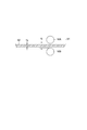
- FIG. 6 is a flowchart showing a process performed by the control device according to the embodiment. It is a schematic diagram which shows the state of the rolling roll and the metal plate at the time of rolling start. It is a schematic diagram which shows the state of the rolling roll and the metal plate at the time of rolling start. It is a schematic diagram which shows the state of the rolling roll and the metal plate at the time of rolling start. It is a figure which shows the roll speed Vm of a rolling roll at the time of a rolling start, and the time change of the entrance side tension Te applied to a metal plate. It is a flow chart which shows a part of processing by a control device concerning one embodiment. It is a flow chart which shows a part of processing by a control device concerning one embodiment.
- FIG. 1 is a schematic configuration diagram of rolling equipment including a control device according to an embodiment.
- the rolling installation 1 includes a rolling mill 2 and a control device 30 for controlling the rolling mill 2.
- the rolling apparatus 2 shown in FIG. 1 is a rolling apparatus (reverse mill) that reciprocates and rolls the metal plate 50 passed between the pair of rolling rolls 16A and 16B.
- the rolling apparatus 2 includes a rolling mill 10 including a pair of rolling rolls (work rolls) 16A and 16B provided so as to sandwich a metal plate 50, which is a rolling material, and rolling rolls 16A and 16B in the traveling direction of the metal plate 50.
- the pair of rolling rolls 16A, 16B includes the unwinding device 4 provided on the entrance side and the winding device 14 provided on the exit side of the rolling rolls 16A, 16B in the traveling direction of the metal plate 50. It is configured to be rolled by.
- the rolling mill 10 includes, in addition to the pair of rolling rolls (work rolls) 16A and 16B, the pair of intermediate rolls 18A and 18B provided on the opposite side of the metal plate 50 with the pair of rolling rolls 16A and 16B sandwiched therebetween. It includes a pair of backup rolls 20A and 20B. The intermediate rolls 18A, 18B and the backup rolls 20A, 20B are configured to support the rolling rolls 16A, 16B. Further, the rolling mill 10 includes a rolling-down device 22 for applying a load to the pair of rolling rolls 16A and 16B to roll down the metal plate 50 sandwiched between the outer pair of rolling rolls 16A and 16B.
- the reduction device 22 may include a hydraulic cylinder.
- a motor 11 is connected to the rolling rolls 16A and 16B via a spindle (not shown) or the like, and the rolling rolls 16A and 16B are rotationally driven by the motor 11.
- a frictional force is generated between the rolling rolls 16A and 16B and the metal plate 50. Due to this frictional force, the metal plate 50 is sent to the exit side of the rolling rolls 16A and 16B.
- the unwinding device 4 is configured to unwind the metal plate 50 toward the rolling mill 10.
- the winding device 14 is configured to wind the metal plate 50 from the rolling mill 10.
- the unwinding device 4 and the winding device 14 are driven by motors 5 and 15, respectively.
- the unwinding device 4 is configured to apply an entrance tension to the metal plate 50 when the metal plate 50 is rolled. Further, the winding device 14 is configured to apply an outlet tension to the metal plate 50 when the metal plate 50 is rolled. That is, by appropriately driving the unwinding device 4 and the winding device 14 by the motors 5 and 15, the entrance side tension and the exit side tension are applied to the metal plate 50. By appropriately applying the entrance side tension and the exit side tension to the metal plate 50, it is possible to suppress the meandering of the metal plate 50 during rolling.
- the winding device 14 When the rolling is stopped just before the tail end of the metal plate 50 unwound from the unwinding device 4 and the rolling is completed with the metal plate 50 being rolled down by the rolling rolls 16A and 16B, then the winding device 14 The metal plate 50 is unwound toward the rolling mill 10 and the metal plate 50 is rolled by the unwinding device 4, while the metal plate 50 is rolled in the direction opposite to the preceding direction. That is, the role of the unwinding device 4 and the role of the winding device 14 are switched depending on the traveling direction of the metal plate 50.
- the rolling device 2 includes an entrance side pinch roll 6 and a side guide 8 for guiding the metal plate 50 introduced from the unwinding device 4 to the rolling mill 10, and a metal plate 50 sent from the rolling mill 10 to the winding device 14. And a delivery pinch roll 12 for guiding the.
- the rolling mill 2 is provided with various measuring instruments.
- speed sensors 32 and 36 for measuring the speeds of the motors 5 and 11, respectively, a tension sensor 34 for measuring the entrance tension acting on the metal plate 50, a rolling roll 16A, A rolling position sensor 37 for detecting the rolling position of 16B, a plate end position detector 38 for measuring the position of the widthwise end of the metal plate 50 on the exit side of the rolling rolls 16A, 16B, and A speed sensor 40 and the like for measuring the speed of the metal plate 50 on the exit side of the rolling rolls 16A and 16B are provided. Signals indicating the measurement results obtained by these measuring instruments are sent to the control device 30.
- the tension sensor 34 for measuring the entrance tension an ammeter for measuring the current of the motor 5 that drives the unwinding device 4 is provided, and the entrance tension is calculated based on the measurement result of the ammeter. You may do so.
- the control device 30 receives signals indicating measurement results from the above-described various measuring instruments, and based on these measurement results, the motor 11 for driving the rolling rolls 16A and 16B and the motor for driving the unwinding device 4. 5 and/or the operation of the reduction device 22 and the like may be controlled.
- the control device 30 may include a CPU, a memory (RAM), an auxiliary storage unit, an interface, and the like.
- the control device 30 is adapted to receive signals from the various measuring instruments described above via an interface.
- the CPU is arranged to process the signals thus received.
- the CPU is configured to process the program loaded in the memory.
- the processing content of the control device 30 may be implemented as a program executed by the CPU and stored in the auxiliary storage unit. When the programs are executed, these programs are expanded in the memory. The CPU reads the program from the memory and executes the instructions included in the program.
- the control of the rolling device 2 described below is a control when starting the rolling of the metal plate 50 wound by the unwinding device 4. In addition, you may make it operate the rolling mill 2 by manually performing a part or all of the process by the control apparatus 30 demonstrated below.
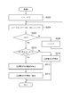
- FIG. 2 is a flowchart showing processing by the control device 30 according to the embodiment.
- 3 to 5 are schematic diagrams showing the states of the rolling rolls 16A and 16B and the metal plate 50 when the rolling of the metal plate 50 is started under the control of the control device 30, respectively.
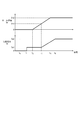
- FIG. 6 shows the time variation of the speed (peripheral speed) Vm of the rolling rolls 16A and 16B and the inlet side tension Te applied to the metal plate 50 when the rolling of the metal plate 50 is started under the control of the controller 30.
- FIG. 1 is a flowchart showing processing by the control device 30 according to the embodiment.
- 3 to 5 are schematic diagrams showing the states of the rolling rolls 16A and 16B and the metal plate 50 when the rolling of the metal plate 50 is started under the control of the control device 30, respectively.
- FIG. 6 shows the time variation of the speed (peripheral speed) Vm of the rolling rolls 16A and 16B and the inlet side tension Te applied to the metal plate 50 when the rolling of the metal plate 50 is started under the control of
- the control device 30 first sets a pair of rolling rolls 16A and 16B so that the gap (roll gap) is larger than the thickness of the metal plate 50.
- the positions of the rolling rolls 16A and 16B are adjusted (step S102).
- the reduction device 22 may be operated to adjust the positions of the pair of rolling rolls 16A and 16B.
- the tip portion 51 (see FIG. 3) of the metal plate 50 is passed between the pair of rolling rolls 16A and 16B while maintaining the gap between the rolls larger than the plate thickness (step S104).
- FIG. 3 is a schematic diagram showing the state of the rolling rolls 16A and 16B and the metal plate 50 when step S104 is completed.
- the tip portion 51 of the metal plate 50 is in a state in which the gap d0 between the pair of rolling rolls 16A and 16B is larger than the plate thickness H0 of the metal plate 50 before rolling. Is passed between the rolling rolls 16A and 16B.
- the front end portion 51 of the metal plate 50 is located on the exit side of the rolling rolls 16A and 16B and does not reach the winding device 14. Therefore, the output side tension Td acting on the metal plate 50 is zero. Further, at this time point, since the entrance side tension Te is not applied to the metal plate 50, the entrance side tension Te is also zero.
- step S106 the reduction device 22 is operated based on the measurement result of the reduction position sensor 37 so that the roll gap has a value suitable for rolling.
- FIG. 4 is a schematic diagram showing a state of the rolling rolls 16A and 16B and the metal plate 50 when step S108 is completed. As shown in FIG. 4, the inter-roll gap d1 at the time of completion of step S108 is smaller than the plate thickness H0 of the metal plate 50 before rolling.
- step S108 the inlet side tension Te applied to the metal plate 50 by the unwinding device 4 is made larger than zero (step S108, time t1 in FIG. 6), and the pair of rolling rolls 16A and 16B is started to rotate to start rolling. (Step S110, time t2 in FIG. 6). In addition, in steps S108 and S110, the outlet tension Td is maintained at zero.
- step S108 the entry-side tension Te acting on the metal plate 50 is made larger than zero by appropriately adjusting the current value of the motor 5 for driving the unwinding device 4.
- the entrance-side tension Te is set to a constant value Te1 which is larger than zero, and keeps a constant value until the entrance-side tension Te starts increasing at step S114 (time t3 in FIG. 6) described later. May be maintained.
- step S109 rotation of the rolling rolls 16A and 16B is started by appropriately adjusting the current value of the motor 11 for driving the rolling rolls 16A and 16B.
- step S110 the metal plate 50 advances in the direction of the arrow shown in FIG.
- FIG. 5 is a schematic diagram showing the state of the rolling rolls 16A and 16B and the metal plate 50 when the rolling is started in step S110. As shown in FIG. 5, a portion of the metal plate 50 that has been rolled down to the exit side of the rolling rolls 16A and 16B by being rolled by the rolling rolls 16A and 16B has a plate thickness H1 thinner than the plate thickness H0 before rolling. doing.
- the exit tension Td applied to the metal plate 50 is zero.
- the metal plate 50 is rolled down by the pair of rolling rolls 16A and 16B, and the rolling of the metal rolls 50 is started by starting the rotation of the rolling rolls 16A and 16B while giving the entrance tension Te larger than zero to the metal plate 50.
- the rolling can be appropriately performed while suppressing the meandering of the metal plate 50, even though the exit side tension Td is zero. Therefore, for example, rolling can be started from a portion near the tip of the metal plate 50 without using a lead material or the like as described in Patent Document 1, and the yield of the metal plate 50 is improved with a simple configuration. be able to.
- step S110 After the rolling of the rolling rolls 16A and 16B is started in step S110 to start rolling, the speed (rolling speed Vm) of the rolling rolls 16A and 16B is increased (step S112, time t2 to t4 in FIG. 6). Then, after the time t2, the entrance tension Te applied to the metal plate 50 is increased (step S114, time t3 in FIG. 6), and the entrance tension Te is adjusted so that the entrance tension Te does not exceed the specified range ( Step S116, times t3 to t5 in FIG. 6). In step S112, the speed (roll speed Vm) of the rolling rolls 16A and 16B is increased by appropriately adjusting the current value of the motor 11 for driving the rolling rolls 16A and 16B. In steps S114 and S116, the entrance-side tension Te acting on the metal plate 50 is increased within the specified range by appropriately adjusting the current value of the motor 5 for driving the unwinding device 4.
- the entrance side tension Te As described above, by applying the entrance side tension Te to the metal plate 50, it is possible to perform rolling while suppressing the meandering of the metal plate 50 even when the exit side tension Td is zero. If the entrance side tension Te of 50 is excessively large, the metal plate 50 may not advance to the exit side of the rolling rolls 16A and 16B easily (that is, slip may easily occur), and appropriate rolling may not be possible. .. In this respect, as described above, by increasing the inlet side tension Te applied to the metal plate 50 (step S114) and adjusting it within an appropriate range so that slip does not occur (step S116), the outlet side is tensionless. During rolling in this state, meandering of the metal plate 50 can be suppressed more effectively, and rolling can be performed more appropriately.
- the entry-side tension Te is increased while the roll speed Vm is low, the relative speed of the metal plate 50 with respect to the roll speed Vm will be decreased, and therefore the metal plate 50 will not move to the rolling rolls 16A and 16B. In some cases, the phenomenon of not advancing to the exit side may easily occur.
- the step By increasing the entrance tension Te in S114 to S116, the entrance tension Te can be stably increased.
- Step S116 of adjusting the entrance side tension Te so as not to exceed the specified range is repeatedly executed until the tip of the metal plate 50 reaches the winding device 14 (No in step S118).
- the output side tension Td becomes larger than zero (Yes in step S118; that is, when the metal plate 50 starts to be wound by the winding device 14)
- the flow shown in FIG. 2 (when the output side is in a tensionless state) Flow control for appropriately performing rolling) is stopped, and normal control is performed when the outlet tension Td is larger than zero.
- step S116 the entry side tension Te is adjusted so as not to exceed the specified range.
- step S116 the entrance tension Te is adjusted so that the exit speed Vd of the metal plate 50 is equal to or higher than the roll speed (rotation speed) Vm of the rolling rolls 16A and 16B.
- the control device 30 sets the entrance tension Te within an appropriate range based on the exit speed Vd measured by the speed sensor 40 and the roll speed Vm calculated from the speed of the motor 11 measured by the speed sensor 36.
- the current value of the motor 5 is appropriately adjusted so that
- the exit side speed Vd of the metal plate 50 being less than the rotational speed Vm of the rolling rolls 16A and 16B means that the metal plate 50 has not advanced to the rolling rolls 16A and 16B on the exit side of the rolling rolls 16A and 16B. (That is, the metal plate 50 has started to slip or is likely to slip with respect to the rolling rolls 16A and 16B), and in this case, appropriate rolling may not be possible.
- the inlet side tension Te applied to the metal plate 50 is adjusted so that the outlet speed Vd of the metal plate 50 becomes equal to or higher than the roll speed (rotational speed) Vm of the rolling rolls 16A and 16B.
- the rotation speed Vm of the rolling rolls 16A and 16B is measured a prescribed number of times for each prescribed period, and the exit speed Vd of the metal plate 50 is set to the roll of the rolling rolls 16A and 16B by using the measurement results of all or a part of the prescribed number of times.
- the entry side tension Te applied to the metal plate 50 may be adjusted so as to be equal to or higher than the speed (rotation speed) Vm.
- step S116 the exit speed Vd of the metal plate 50 that is measured a plurality of times for each specified period is acquired, and the entrance tension Te is set based on the measurement results of the exit speed Vd over a plurality of times. Adjust.
- the exit speed Vd of the metal plate 50 can be an index as to whether or not the metal plate 50 slips on the rolling rolls 16A and 16B.
- the outgoing speed Vd of the metal plate 50 is measured a plurality of times for each specified period, it is possible to grasp the change in the outgoing speed Vd with time. Therefore, by adjusting the entrance side tension Te applied to the metal plate 50 based on the measurement result of the exit side speed Vd for a plurality of times, the slip of the metal plate 50 with respect to the rolling rolls 16A and 16B in the tension-free state on the exit side. It is possible to perform rolling appropriately while appropriately suppressing.
- the entrance side tension Te is increased. Stop.
- the fact that the metal plate 50 has not advanced to the exit side of the rolling rolls 16A and 16B means that the metal plate 50 may have started to slip with respect to the rolling rolls 16A and 16B or may slip in the near future (of slippage). Signs).
- the increase of the entrance side tension Te is stopped, so that the exit side is untensioned. In this state, it is possible to perform rolling appropriately while more reliably suppressing the slip of the metal plate 50 on the rolling rolls 16A and 16B.
- the advance of the metal plate 50 is measured a specified number of times for each specified period, and it is detected that the metal plate 50 is not advanced to the exit side of the rolling rolls 16A and 16B in the measurement result of all or a part of the specified number of times. You may do it.
- the fact that the metal plate 50 has not advanced to the exit side of the rolling rolls 16A and 16B may be detected, for example, by monitoring the metal plate 50 near the rolling rolls 16A and 16B using a camera.
- the fact that the metal plate 50 has not advanced to the exit side of the rolling rolls 16A, 16B may be detected using, for example, the exit speed Vd measured a specified number of times for each specified period.
- the step S116 acquires the exit speed Vd measured a specified number of times for a specified period, and the exit speed Vd i measured at the i-th time and the (i-1)th time.
- the difference with the delivery speed Vd (i-1) is all negative, it is considered that the metal plate 50 has not advanced to the delivery side of the rolling rolls 16A and 16B, and the increase of the entry side tension Te is stopped. It may be.
- FIG. 7 is a flowchart of step S116 according to this embodiment.
- step S116 acquires the exit speed Vd measured a specified number of times for each specified period, and measures the exit speed Vd i measured at the i-th time and the (i-1)th time.
- the integrated value of the difference between the calculated output speed Vd (i-1) is less than the specified value, it is considered that the metal plate 50 has not advanced to the output side of the rolling rolls 16A, 16B, and the input tension Te of The increase may be stopped.
- FIG. 8 is a flowchart of step S116 according to this embodiment.
- Vd (i-1)) (the exit side speed vd i that is measured in the i-th, (i-1) is calculated integral value of the difference between the time the measured output side speed Vd (i-1)) It Then, it is determined whether or not ⁇ Vi is smaller than the specified value C (where C is a negative number) (step S230).
- step S230 When ⁇ Vi is equal to or more than the above-mentioned specified value C (No in step S230), the exit speed Vd does not tend to decrease, and it is determined that slip is unlikely to occur, and therefore the entrance tension Te is increased. Continue (step S236). On the other hand, when ⁇ Vi is less than the specified value C (Yes in step S230), the exit speed Vd tends to decrease, and it is determined that slippage of the metal plate 50 is likely to occur. The increase of the side tension Te is stopped (step S232). When the increase of the entrance side tension Te is stopped in this way, the entrance side tension Te is decreased by a specified amount (step S234).
- the exit-side speed Vd i that is measured in the i-th, the difference between the (i-1) th to the measured exit side speed Vd (i-1), or, the delivery side speed measured in time th and Vd i, (i-1) th based on the integrated value of the difference between the measured output side speed Vd (i-1), the can know the possibility of slip occurring in the near future, the possibility Since the increase of the entrance side tension Te is stopped when the value is high, the rolling is appropriately performed while the slippage of the metal plate 50 with respect to the rolling rolls 16A and 16B is more surely suppressed in the state where the exit side has no tension. be able to.
- control relating to the adjustment of the entrance tension Te is performed by using the exit speed Vd measured a specified number of times for each specified period, but another embodiment.
- control relating to the adjustment of the entrance side tension Te may be performed by using the exit side speed Vd measured for each specified period during the specified length of time.
- the exit speed Vd of the metal plate 50 and the roll speed Vm that is the peripheral speed of the rolling rolls 16A and 16B are acquired, and the difference (Vd) between the exit speed Vd of the metal plate 50 and the roll speed Vm is acquired. -Vm) based on the input side tension Te.
- the difference (Vd ⁇ Vm) between the exit speed Vd of the metal plate 50 and the roll speed Vm can be an index as to whether or not slippage of the metal plate 50 with respect to the rolling rolls 16A and 16B occurs.
- the inlet side tension Te applied to the metal plate 50 on the basis of the difference (Vd ⁇ Vm) between the outlet side velocity Vd of the metal plate 50 and the roll velocity Vm, the outlet side is eliminated. In the state of tension, it is possible to appropriately perform rolling while appropriately suppressing the slip of the metal plate 50 on the rolling rolls 16A and 16B.
- the entrance side tension Te is decreased by a specified amount. It may be configured as follows. For example, in the flowcharts shown in FIGS. 7 and 8, after the increase of the entrance side tension Te is stopped in steps S212 and S232, the entrance side tension Te is decreased by a specified amount (steps S214 and S234). In this way, by stopping the increase of the entrance side tension Te in order to suppress the slip and then decreasing the entrance side tension Te by a specified amount, the rolling roll of the metal plate 50 is in a tensionless state on the exit side. Appropriate rolling can be performed while further reliably suppressing slipping on 16A and 16B.
- the control device for a rolling mill is A pair of rolling rolls provided so as to sandwich the metal plate, and an unwinding device for unwinding the metal plate on the entrance side of the rolling roll in the traveling direction of the metal plate, and the metal plate
- the metal plate is rolled down by the pair of rolling rolls with the output side tension applied to the metal plate being zero. Since the rolling of the rolling roll is started by applying the entrance tension larger than zero to the metal plate to start the rolling of the metal plate, the meandering of the metal plate is achieved even if the exit tension is zero.
- the rolling can be appropriately performed while suppressing the above. Therefore, the rolling can be started from a portion close to the tip of the metal plate without using a lead material or the like, and the yield of the metal plate can be improved with a simple configuration.
- the control device is After the rotation of the rolling roll is started, the entrance tension applied to the metal plate is zero, and the entrance tension is increased within a specified range.
- the inlet side tension applied to the metal plate is zero, and the inlet side tension is increased within the specified range.
- meandering of the metal plate can be suppressed more effectively, and rolling can be performed more appropriately.
- the control device is The entrance tension is adjusted so that the exit speed Vd of the metal plate is equal to or higher than the rotation speed Vm of the rolling roll.
- the exit speed Vd of the metal plate being less than the rotation speed Vm of the rolling roll means that the metal plate is not advanced with respect to the rolling roll on the exit side of the rolling roll (that is, the metal plate is relative to the rolling roll). (Meaning that slip has started or is about to slip), in which case proper rolling may not be possible.
- the inlet tension applied to the metal plate is adjusted so that the outlet speed Vd of the metal plate becomes equal to or higher than the rotation speed Vm of the rolling roll. In the state of no tension, it is possible to perform more appropriate rolling while appropriately suppressing slip (slip) of the metal plate with respect to the rolling roll.
- the control device is The output side velocity Vd of the metal plate measured a plurality of times for each prescribed period is acquired, and the inlet side tension is adjusted based on the measurement results of the output side velocity Vd over the plurality of times.
- the exit speed Vd of the metal plate can be an index of whether or not slippage of the metal plate with respect to the rolling roll occurs.
- the outgoing speed Vd of the metal plate is measured a plurality of times for each prescribed period, it is possible to grasp the change over time of the outgoing speed Vd. .. Therefore, by adjusting the inlet side tension applied to the metal plate based on the measurement result of the outlet side speed Vd over a plurality of times, while appropriately suppressing the slip of the metal plate with respect to the rolling roll in the state where the outlet side is in a tension-free state, Appropriate rolling can be performed.
- the control device is When the exit side tension applied to the metal plate is zero and it is detected that the metal plate has not advanced to the exit side of the rolling roll, the increase of the entrance side tension is stopped.
- the fact that the metal plate has not advanced to the exit side of the rolling roll indicates that the metal plate has begun to slip with respect to the rolling roll or may slip in the near future (a sign of slip).
- the increase of the entrance side tension is stopped, so that the exit side is in the state of no tension.
- the rolling can be appropriately performed while more reliably suppressing the slip of the metal plate with respect to the rolling roll.
- the control device is The exit speed Vd measured a specified number of times for each specified period is acquired, and the exit speed Vd i measured for the i-th time and the exit speed Vd (i-1) measured for the (i-1)th time. When the difference between and is all negative, it is configured to stop the increase of the entrance side tension.
- the control device is The exit speed Vd measured a specified number of times for each specified period is acquired, and the exit speed Vd i measured for the i-th time and the exit speed Vd (i-1) measured for the (i-1)th time.
- the increase of the inlet tension is stopped.
- the integral value of the difference between the (i-1) th to the measured exit side speed Vd (i-1) defined If the value is less than the value, that is, if the exit speed Vd is gradually decreased while the exit speed Vd is measured a specified number of times in a specified period, and slip is likely to occur in the near future, Since the increase of the tension is stopped, it is possible to perform the rolling properly while more reliably suppressing the slip of the metal plate with respect to the rolling roll in the state where the exit side is tensionless.
- the control device is After stopping the increase of the inlet tension, the inlet tension is reduced by a specified amount.
- the entrance side tension is decreased by the specified amount, so that the exit side is in the state of no tension and the metal plate Appropriate rolling can be performed while further reliably suppressing slip on the rolling rolls.
- the control device is The exit speed Vd of the metal plate and the roll speed Vm, which is the peripheral speed of the rolling roll, are obtained, and the input speed is calculated based on the difference (Vd ⁇ Vm) between the exit speed Vd of the metal plate and the roll speed Vm. Configured to adjust lateral tension.
- the difference (Vd-Vm) between the exit speed Vd of the metal plate and the roll speed Vm can be an index as to whether or not slippage of the metal plate with respect to the rolling roll occurs.
- the output side is adjusted by adjusting the input side tension applied to the metal plate based on the difference (Vd ⁇ Vm) between the output speed Vd of the metal plate and the roll speed Vm. In the state of no tension, it is possible to appropriately perform rolling while appropriately suppressing the slip of the metal plate on the rolling roll.
- the rolling equipment according to at least one embodiment of the present invention is A pair of rolling rolls provided so as to sandwich the metal plate, and an unwinding device for unwinding the metal plate on the entrance side of the rolling roll in the traveling direction of the metal plate, and the metal plate A rolling device configured to roll by a pair of rolling rolls,
- the control device according to any one of (1) to (9) above.
- the metal plate is rolled down by the pair of rolling rolls in a state where the output side tension applied to the metal plate is zero. Since the rolling of the rolling roll is started by applying the entrance tension larger than zero to the metal plate to start the rolling of the metal plate, the meandering of the metal plate is achieved even if the exit tension is zero.
- the rolling can be appropriately performed while suppressing the above. Therefore, the rolling can be started from a position close to the tip of the metal plate without using a lead material or the like, and the yield of the metal plate can be improved with a simple configuration.
- a method for operating a rolling mill is An unwinding device for applying an entrance side tension to the metal plate, and a pair of rolling rolls provided so as to sandwich the metal plate on the exit side of the unwinding device in the traveling direction of the metal plate, and A method for operating a rolling device configured to roll a metal plate by the pair of rolling rolls, A gap between the pair of rolling rolls, a plate passing step of passing the tip of the metal plate between the pair of rolling rolls in a state of being larger than the plate thickness of the metal plate, After the passing step, in a state where the output side tension applied to the metal plate is zero, a reduction step of reducing the metal plate by the pair of rolling rolls, After the rolling-down step, in a state where the tension on the outgoing side applied to the metal plate is zero, a tension applying step for making the incoming tension applied to the metallic plate by the unwinding device larger than zero, After the tension applying step, in a state where the exit side tension applied to the metal plate is zero, a
- the metal plate is rolled down by the pair of rolling rolls in a state where the output side tension applied to the metal plate is zero. Since the rolling of the rolling roll is started by applying the entrance tension larger than zero to the metal plate to start the rolling of the metal plate, the meandering of the metal plate is achieved even if the exit tension is zero.
- the rolling can be appropriately performed while suppressing the above. Therefore, the rolling can be started from a portion close to the tip of the metal plate without using a lead material or the like, and the yield of the metal plate can be improved with a simple configuration.
- the inlet tension is increased within a specified range with the outlet tension applied to the metal plate being zero.
- the inlet side tension applied to the metal plate is zero, and the inlet side tension is increased within the specified range.
- meandering of the metal plate can be suppressed more effectively, and rolling can be performed more appropriately.
- the entrance tension is adjusted so that the exit speed Vd of the metal plate is equal to or higher than the rotation speed Vm of the rolling roll.
- the exit side speed Vd of the metal plate being less than the rotation speed Vm of the rolling roll means that the metal plate is not advanced with respect to the rolling roll on the exit side of the rolling roll. There are things you can't do.
- the entrance side tension applied to the metal plate is adjusted so that the exit side speed Vd of the metal plate becomes equal to or higher than the rotation speed Vm of the rolling roll. In the state of no tension, it is possible to perform more appropriate rolling while appropriately suppressing slip (slip) of the metal plate with respect to the rolling roll.
- the exit speed Vd of the metal plate can be an index of whether or not slippage of the metal plate with respect to the rolling roll occurs.
- the output speed Vd of the metal plate is measured a plurality of times for each prescribed period, it is possible to grasp the change in the output speed Vd with time. .. Therefore, by adjusting the inlet side tension applied to the metal plate based on the measurement result of the outlet side speed Vd over a plurality of times, while appropriately suppressing the slip of the metal plate with respect to the rolling roll in the state where the outlet side is in a tension-free state, Appropriate rolling can be performed.
- the fact that the metal plate has not advanced to the exit side of the rolling roll indicates that the metal plate has begun to slip with respect to the rolling roll or may slip in the near future (a sign of slip).
- the increase of the entrance side tension is stopped, so that the exit side is in a tensionless state.
- the rolling can be appropriately performed while more reliably suppressing the slip of the metal plate with respect to the rolling roll.
- the exit-side speed Vd i that is measured in the i-th, the integral value of the difference between the (i-1) th to the measured exit side speed Vd (i-1) defined If the value is less than the value, that is, if the exit speed Vd is gradually decreased while the exit speed Vd is measured a specified number of times in a specified period, and slip is likely to occur in the near future, Since the increase of the tension is stopped, it is possible to perform the rolling properly while more reliably suppressing the slip of the metal plate with respect to the rolling roll in the state where the exit side is tensionless.
- the inlet tension is reduced by a specified amount.
- the increase of the entrance side tension is stopped in order to suppress the slip, and then the entrance side tension is reduced by a specified amount.
- Appropriate rolling can be performed while further reliably suppressing slip on the rolling rolls.
- expressions representing shapes such as a quadrangle and a cylinder are not limited to shapes such as a quadrangle and a cylinder in a geometrically strict sense, and are within a range in which the same effect can be obtained. A shape including an uneven portion and a chamfered portion is also shown. Further, in this specification, the expressions “comprising”, “including”, or “having” one element are not exclusive expressions excluding the existence of other elements.
Landscapes
- Engineering & Computer Science (AREA)
- Mechanical Engineering (AREA)
- Control Of Metal Rolling (AREA)
- Winding, Rewinding, Material Storage Devices (AREA)
Abstract
圧延装置の制御装置は、金属板を挟むように設けられる一対の圧延ロールと、前記金属板の進行方向にて前記圧延ロールの入側において前記金属板を巻き出すための巻き出し装置と、を含み、前記金属板を前記一対の圧延ロールにより圧延するように構成された圧延装置を制御するための制御装置であって、前記一対の圧延ロール間のギャップが前記金属板の板厚よりも大きい状態で前記金属板の先端部を前記一対の圧延ロールの間に通した後、前記金属板に加える出側張力がゼロの状態で、前記一対の圧延ロールにより前記金属板を圧下し、前記巻き出し装置により前記金属板に与える入側張力をゼロより大きくし、前記一対の圧延ロールの回転を開始させるように構成される。
Description
本開示は、圧延装置の制御装置及び圧延設備並びに圧延装置の運転方法に関する。
一対の圧延ロール間に通された金属板を往復させて圧延させる圧延装置(リバースミル)では、通常、金属板の進行方向において圧延ロールの両側に設けられる巻き出し装置及び巻き取り装置に金属板が巻き付いた状態で、圧延ロールを圧下及び回転させるとともに、巻き出し装置及び巻き取り装置により金属板に張力を与えながら圧延を行う。このような圧延装置では、圧延の開始時に金属板の先端部を巻き取り装置に巻き付けた状態とする必要がある。このため、金属板のうち、圧延開始時に圧延ロールよりも巻き取り装置側にある部分については圧延することができず、この部分を製品にすることができない。
そこで、金属板の歩留まりを改善するための構成が提案されている。例えば、特許文献1では、金属板の先端にリーダー片(リード材料)を溶接により接合し、このリーダー片を巻き取り装置で巻き取ることで、リーダー片を介して金属板に出側張力を与えながら圧延を開始することが記載されている。このようにリーダー片を接合した状態で圧延を開始することにより、金属板のより先端側の位置から圧延を行い、歩留まりを改善することが図られている。
しかしながら、特許文献1のようにリード材料を用いる場合、圧延する金属板毎に毎回接合作業を行う必要があり、手間やコストがかかり、また、接合用の装置も必要となる。
そこで、より簡素な構成で、歩留まりを改善することが望まれる。
そこで、より簡素な構成で、歩留まりを改善することが望まれる。
上述の事情に鑑みて、本発明の少なくとも一実施形態は、簡素な構成で、金属板の歩留まりを改善可能な圧延装置の制御装置及び圧延設備並びに圧延装置の運転方法を提供することを目的とする。
(1)本発明の少なくとも一実施形態に係る圧延装置の制御装置は、
金属板を挟むように設けられる一対の圧延ロールと、前記金属板の進行方向にて前記圧延ロールの入側において前記金属板を巻き出すための巻き出し装置と、を含み、前記金属板を前記一対の圧延ロールにより圧延するように構成された圧延装置を制御するための制御装置であって、
前記一対の圧延ロール間のギャップが前記金属板の板厚よりも大きい状態で前記金属板の先端部を前記一対の圧延ロールの間に通した後、前記金属板に加える出側張力がゼロの状態で、前記一対の圧延ロールにより前記金属板を圧下し、前記巻き出し装置により前記金属板に与える入側張力をゼロより大きくし、前記一対の圧延ロールの回転を開始させるように構成される。
金属板を挟むように設けられる一対の圧延ロールと、前記金属板の進行方向にて前記圧延ロールの入側において前記金属板を巻き出すための巻き出し装置と、を含み、前記金属板を前記一対の圧延ロールにより圧延するように構成された圧延装置を制御するための制御装置であって、
前記一対の圧延ロール間のギャップが前記金属板の板厚よりも大きい状態で前記金属板の先端部を前記一対の圧延ロールの間に通した後、前記金属板に加える出側張力がゼロの状態で、前記一対の圧延ロールにより前記金属板を圧下し、前記巻き出し装置により前記金属板に与える入側張力をゼロより大きくし、前記一対の圧延ロールの回転を開始させるように構成される。
本発明の少なくとも一実施形態によれば、簡素な構成で、金属板の歩留まりを改善可能な圧延装置の制御装置及び圧延設備並びに圧延装置の運転方法が提供される。
以下、添付図面を参照して本発明の幾つかの実施形態について説明する。ただし、実施形態として記載されている又は図面に示されている構成部品の寸法、材質、形状、その相対的配置等は、本発明の範囲をこれに限定する趣旨ではなく、単なる説明例にすぎない。
まず、幾つかの実施形態に係る圧延装置を含む圧延設備の全体構成について説明する。
図1は、一実施形態に係る制御装置を備えた圧延設備の概略構成図である。図1に示すように、圧延設備1は、圧延装置2と、圧延装置2を制御するための制御装置30と、を備えている。
図1は、一実施形態に係る制御装置を備えた圧延設備の概略構成図である。図1に示すように、圧延設備1は、圧延装置2と、圧延装置2を制御するための制御装置30と、を備えている。
図1に示す圧延装置2は、一対の圧延ロール16A,16B間に通された金属板50を往復させて圧延させる圧延装置(リバースミル)である。圧延装置2は、圧延材料である金属板50を挟むように設けられる一対の圧延ロール(ワークロール)16A,16Bを含む圧延機10と、金属板50の進行方向にて圧延ロール16A,16Bの入側に設けられる巻き出し装置4と、金属板50の進行方向にて圧延ロール16A,16Bの出側に設けられる巻き取り装置14と、を含み、金属板50を一対の圧延ロール16A,16Bにより圧延するように構成されている。
圧延機10は、一対の圧延ロール(ワークロール)16A,16Bに加え、一対の圧延ロール16A,16Bをそれぞれ挟んで金属板50とは、それぞれ反対側に設けられる一対の中間ロール18A,18B及び一対のバックアップロール20A,20Bと、を含む。中間ロール18A,18B及びバックアップロール20A,20Bは、圧延ロール16A,16Bを支持するように構成されている。また、圧延機10は、一対の圧延ロール16A,16Bに荷重を加えて外一対の圧延ロール16A,16Bに挟まれる金属板50を圧下するための圧下装置22を備えている。圧下装置22は、油圧シリンダを含んでいてもよい。
圧延ロール16A,16Bには、不図示のスピンドル等を介してモータ11が接続されており、圧延ロール16A,16Bは、モータ11によって回転駆動されるようになっている。金属板50の圧延時には、圧下装置22で金属板50を圧下しながらモータ11により圧延ロール16A,16Bを回転させることで、圧延ロール16A,16Bと金属板50との間に摩擦力が生じ、この摩擦力によって金属板50が圧延ロール16A,16Bの出側へと送られるようになっている。
巻き出し装置4は、圧延機10に向けて金属板50を巻き出すように構成されている。巻き取り装置14は、圧延機10からの金属板50を巻き取るように構成されている。巻き出し装置4及び巻き取り装置14は、それぞれモータ5、15により駆動されるようになっている。
巻き出し装置4は、金属板50の圧延時に、金属板50に入側張力を与えるように構成されている。また、巻き取り装置14は、金属板50の圧延時に、金属板50に出側張力を与えるように構成されている。すなわち、モータ5,15によって巻き出し装置4及び巻き取り装置14を適切に駆動することにより、金属板50に入側張力及び出側張力を与えるようになっている。金属板50に適切に入側張力及び出側張力を与えることにより、圧延時における金属板50の蛇行を抑制することができる。
なお、巻き出し装置4から巻き出される金属板50の尾端直前で圧延を止め、金属板50が圧延ロール16A,16Bに圧下された状態で圧延が完了したら、その次に、巻き取り装置14から金属板50を圧延機10に向けて巻き出すとともに、巻き出し装置4で金属板50を巻き取りながら、先ほどとは逆の進行方向に金属板50を進行させて圧延を行う。すなわち、金属板50の進行方向に応じて、巻き出し装置4の役割と及び巻き取り装置14の役割とが入れ替わるようになっている。
圧延装置2は、巻き出し装置4から圧延機10に導入される金属板50をガイドするための入側ピンチロール6及びサイドガイド8と、圧延機10から巻き取り装置14に送られる金属板50をガイドするための出側ピンチロール12と、をさらに含む。
また、圧延装置2には、各種計測器が設けられている。図1に示す圧延装置2には、モータ5,11の速度をそれぞれ計測するための速度センサ32,36、金属板50に作用する入側張力を計測するための張力センサ34、圧延ロール16A,16Bの圧下位置を検出するための圧下位置センサ37、圧延ロール16A,16Bの出側における金属板50の板の幅方向の端部の位置を計測するための板端位置検出器38、及び、圧延ロール16A,16Bの出側における金属板50の速度を計測するための速度センサ40等が設けられている。これらの計測器による計測結果を示す信号は、制御装置30に送られるようになっている。なお、入側張力を計測するための張力センサ34に代えて、巻き出し装置4を駆動するモータ5の電流を計測する電流計を設け、該電流計の計測結果に基づいて入側張力を算出するようにしてもよい。
制御装置30は、上述の各種計測器から計測結果を示す信号を受け取り、これらの計測結果に基づいて、圧延ロール16A,16Bを駆動するためのモータ11、巻き出し装置4を駆動するためのモータ5、及び/又は圧下装置22等の動作を制御するようになっていてもよい。
制御装置30は、CPU、メモリ(RAM)、補助記憶部及びインターフェース等を含んでいてもよい。制御装置30は、インターフェースを介して、上述の各種計測器からの信号を受け取るようになっている。CPUは、このようにして受け取った信号を処理するように構成される。また、CPUは、メモリに展開されるプログラムを処理するように構成される。
制御装置30での処理内容は、CPUにより実行されるプログラムとして実装され、補助記憶部に記憶されていてもよい。プログラム実行時には、これらのプログラムはメモリに展開される。CPUは、メモリからプログラムを読み出し、プログラムに含まれる命令を実行するようになっている。
次に、上述した制御装置30による圧延装置2の制御について説明する。以下に説明する圧延装置2の制御は、巻き出し装置4に巻かれた金属板50の圧延を開始するときの制御である。なお、以下に説明する制御装置30による処理の一部又は全部をマニュアルで行うことにより圧延装置2を運転するようにしてもよい。
図2は、一実施形態に係る制御装置30による処理を示すフローチャートである。図3~図5は、それぞれ、制御装置30による制御のもとで金属板50の圧延を開始するときの、圧延ロール16A,16B及び金属板50の状態を示す模式図である。図6は、制御装置30による制御のもとで金属板50の圧延を開始するときの、圧延ロール16A,16Bの速度(周速度)Vmと、金属板50に加わる入側張力Teの時間変化を示す図である。
一実施形態では、図2に示すように、制御装置30はまず、一対の圧延ロール16A,16B間のギャップ(ロール間ギャップ)が金属板50の板厚よりも大きい状態となるように一対の圧延ロール16A,16Bの位置を調節する(ステップS102)。この際、必要に応じて圧下装置22を作動させて一対の圧延ロール16A,16Bの位置を調節してもよい。そして、ロール間ギャップが板厚よりも大きい状態を維持したまま、金属板50の先端部51(図3参照)を一対の圧延ロール16A,16Bの間に通す(ステップS104)。
図3は、ステップS104が完了したときの圧延ロール16A,16B及び金属板50の状態を示す模式図である。図3に示すように、ステップS104の完了時点では、一対の圧延ロール16A,16B間のギャップd0が、圧延前の金属板50の板厚H0よりも大きい状態で、金属板50の先端部51が圧延ロール16A,16Bの間を通されている。また、金属板50その先端部51は、圧延ロール16A,16Bの出側に位置しており、巻き取り装置14には達していない。このため、金属板50に作用する出側張力Tdはゼロである。また、この時点では、入側張力Teを金属板50に作用させていないため、入側張力Teもゼロである。
次に、金属板50に加える出側張力Tdがゼロの状態で、一対の圧延ロール16A,16Bにより金属板50を圧下する(ステップS106、図6における時刻t0)。ステップS106では、ロール間ギャップが圧延に適した値となるように、圧下位置センサ37による計測結果に基づいて圧下装置22を作動させる。図4は、ステップS108が完了したときの圧延ロール16A,16B及び金属板50の状態を示す模式図である。図4に示すように、ステップS108の完了時点におけるロール間ギャップd1は、圧延前の金属板50の板厚H0よりも小さい。
そして、巻き出し装置4により金属板50に与える入側張力Teをゼロより大きくし(ステップS108、図6における時刻t1)、一対の圧延ロール16A,16Bの回転を開始させることにより、圧延を開始する(ステップS110、図6における時刻t2)。なお、ステップS108及びS110において、出側張力Tdはゼロで維持されている。
ステップS108では、巻き出し装置4を駆動するためのモータ5の電流値を適切に調節することにより、金属板50に作用する入側張力Teをゼロよりも大きくする。ここで、図6に示すように、入側張力Teは、ゼロよりも大きい規定値Te1とし、後述のステップS114(図6の時刻t3)で入側張力Teを増加し始めるまで、一定値に維持してもよい。
ステップS109では、圧延ロール16A,16Bを駆動するためのモータ11の電流値を適切に調節することにより、圧延ロール16A,16Bの回転を開始させる。なお、ステップS110で圧延を開始すると、金属板50は、図4に示す矢印の方向に向かって進行する。
図5は、ステップS110で圧延を開始したときの圧延ロール16A,16B及び金属板50の状態を示す模式図である。図5に示すように、金属板50のうち、圧延ロール16A、16Bで圧下されて圧延ロール16A,16Bの出側に進行した部分は、圧延前の板厚H0よりも薄い板厚H1を有している。
ここまで説明したように、上述の実施形態によれば、金属板50の先端部51を一対の圧延ロール16A,16Bの間に通した後、金属板50に加える出側張力Tdがゼロの状態で、一対の圧延ロール16A,16Bで金属板50を圧下し、ゼロより大きい入側張力Teを該金属板50に与えながら圧延ロール16A,16Bの回転を開始させて金属板50の圧延を開始するようにしたので、出側張力Tdがゼロであるにもかかわらず、金属板50の蛇行を抑制しながら適切に圧延を行うことができる。よって、例えば特許文献1に記載されるようなリード材料等を用いなくても金属板50の先端に近い部分から圧延を開始することができ、簡素な構成で、金属板50の歩留まりを改善することができる。
図2のフローの続きを説明する。
ステップS110で圧延ロール16A,16Bの回転を開始して圧延を開始した後、圧延ロール16A,16Bの速度(ロール速度Vm)を増加させる(ステップS112,図6の時刻t2~t4)。そして、時刻t2以降に金属板50に加える入側張力Teを増加させ(ステップS114,図6の時刻t3)、入側張力Teが規定範囲を超えないように、入側張力Teを調節する(ステップS116、図6の時刻t3~t5)。
ステップS112では、圧延ロール16A,16Bを駆動するためのモータ11の電流値を適切に調節することにより、圧延ロール16A,16Bの速度(ロール速度Vm)を増加させる。ステップS114,S116では、巻き出し装置4を駆動するためのモータ5の電流値を適切に調節することにより、金属板50に作用する入側張力Teを規定範囲内で増加させる。
ステップS110で圧延ロール16A,16Bの回転を開始して圧延を開始した後、圧延ロール16A,16Bの速度(ロール速度Vm)を増加させる(ステップS112,図6の時刻t2~t4)。そして、時刻t2以降に金属板50に加える入側張力Teを増加させ(ステップS114,図6の時刻t3)、入側張力Teが規定範囲を超えないように、入側張力Teを調節する(ステップS116、図6の時刻t3~t5)。
ステップS112では、圧延ロール16A,16Bを駆動するためのモータ11の電流値を適切に調節することにより、圧延ロール16A,16Bの速度(ロール速度Vm)を増加させる。ステップS114,S116では、巻き出し装置4を駆動するためのモータ5の電流値を適切に調節することにより、金属板50に作用する入側張力Teを規定範囲内で増加させる。
上述したように、入側張力Teを金属板50に与えることで、出側張力Tdがゼロの状態でも金属板50の蛇行を抑制しながら圧延を行うことが可能となるが、一方、金属板50の入側張力Teが過大であると、金属板50が圧延ロール16A,16Bの出側に前進しない事象が生じやすくなり(すなわちスリップが生じやすくなり)、適切な圧延ができなくなる場合がある。
この点、上述のように、金属板50に加える入側張力Teを増加させる(ステップS114)とともに、スリップが生じないような適切な範囲内で調節する(ステップS116)ことにより、出側が無張力の状態での圧延時に、金属板50の蛇行をより効果的に抑制し、より適切に圧延を行うことができる。
この点、上述のように、金属板50に加える入側張力Teを増加させる(ステップS114)とともに、スリップが生じないような適切な範囲内で調節する(ステップS116)ことにより、出側が無張力の状態での圧延時に、金属板50の蛇行をより効果的に抑制し、より適切に圧延を行うことができる。
また、仮に、ロール速度Vmが低い状態で入側張力Teを増加させると、ロール速度Vmに対する金属板50の相対的な速度を低下させることになるため、金属板50が圧延ロール16A,16Bの出側に前進しない事象が生じやすくなる場合がある。この点、上述したように、ステップS112でロール速度Vmをある程度増加させてから(例えば、目標のロール速度Vm2(図6参照)の40%以上60%以下のロール速度Vm1まで増加したら、)ステップS114~S116で入側張力Teを増加させることで、入側張力Teを安定的に増加させることができる。
規定範囲を超えないように入側張力Teを調節するステップS116は、金属板50の先端が巻き取り装置14に到着するまで繰り返し実行される(ステップS118のNo)。一方、出側張力Tdがゼロよりも大きくなったら(ステップS118のYes;すなわち、金属板50が巻き取り装置14に巻き取られ始めたら)、図2に示すフロー(出側が無張力の状態で圧延を適切に行うためのフロー)での制御を止め、出側張力Tdがゼロよりも大きい場合の、通常の制御を行う。
次に、上述のステップS116での処理についてより具体的に説明する。上述したように、ステップS116では、規定範囲を超えないように入側張力Teを調節する。
幾つかの実施形態では、ステップS116では、金属板50の出側速度Vdが圧延ロール16A,16Bのロール速度(回転速度)Vm以上となるように、入側張力Teを調節する。この場合、制御装置30は、速度センサ40により計測される出側速度Vd、速度センサ36により計測されるモータ11の速度から算出したロール速度Vmに基づいて、入側張力Teを適切な範囲内にするように、モータ5の電流値を適切に調節する。
金属板50の出側速度Vdが圧延ロール16A,16Bの回転速度Vm未満であることは、圧延ロール16A,16Bの出側において金属板50が圧延ロール16A,16Bに対して前進していないこと(すなわち、金属板50が圧延ロール16A,16Bに対してスリップし始めていること又はスリップしそうであること)を意味し、この場合、適切に圧延を行うことができないことがある。この点、上述の実施形態では、金属板50の出側速度Vdが圧延ロール16A,16Bのロール速度(回転速度)Vm以上となるように、金属板50に加える入側張力Teを調節するようにしたので、出側が無張力の状態で、金属板50の圧延ロール16A,16Bに対するスリップ(すべり)を適切に抑制しながら、より適切に圧延を行うことができる。
更に、圧延ロール16A,16Bの回転速度Vmを規定期間毎に規定回数計測し、規定回数の全部又は一部の計測結果を用いて金属板50の出側速度Vdが圧延ロール16A,16Bのロール速度(回転速度)Vm以上となるように、金属板50に加える入側張力Teを調節するようにしてもよい。
更に、圧延ロール16A,16Bの回転速度Vmを規定期間毎に規定回数計測し、規定回数の全部又は一部の計測結果を用いて金属板50の出側速度Vdが圧延ロール16A,16Bのロール速度(回転速度)Vm以上となるように、金属板50に加える入側張力Teを調節するようにしてもよい。
幾つかの実施形態では、ステップS116では、規定期間毎に複数回計測された金属板50の出側速度Vdを取得し、出側速度Vdの複数回にわたる計測結果に基づいて入側張力Teを調節する。
金属板50の出側速度Vdは、金属板50の圧延ロール16A,16Bに対するすべりが起きるか否かの指標となり得る。この点、上述の実施形態では、金属板50の出側速度Vdを、規定期間毎に複数回計測するようにしたので、出側速度Vdの時間に伴う変化を把握することができる。よって、出側速度Vdの複数回にわたる計測結果に基づいて金属板50に加える入側張力Teを調節することで、出側が無張力の状態で、金属板50の圧延ロール16A,16Bに対するスリップを適切に抑制しながら、適切に圧延を行うことができる。
幾つかの実施形態では、金属板50に加える出側張力Tdがゼロの状態で、金属板50が圧延ロール16A,16Bの出側へ前進していないことを検出したら入側張力Teの増加を停止する。
金属板50が圧延ロール16A,16Bの出側へ前進していないことは、金属板50が圧延ロール16A,16Bに対してスリップし始めているか、近い将来にスリップする可能性があること(スリップの予兆)を示す。この点、上述の実施形態によれば、金属板50が圧延ロール16A,16Bの出側へ前進していないことを検出したら入側張力Teの増加を停止するようにしたので、出側が無張力の状態で、金属板50の圧延ロール16A,16Bに対するスリップをより確実に抑制しながら、適切に圧延を行うことができる。
更に、金属板50の前進を規定期間毎に規定回数計測し、規定回数の全部又は一部の計測結果において、金属板50が圧延ロール16A,16Bの出側へ前進していないことを検出するようにしてもよい。
更に、金属板50の前進を規定期間毎に規定回数計測し、規定回数の全部又は一部の計測結果において、金属板50が圧延ロール16A,16Bの出側へ前進していないことを検出するようにしてもよい。
金属板50が圧延ロール16A,16Bの出側へ前進していないことは、例えば、圧延ロール16A,16B近傍における金属板50をカメラを用いて監視することによって検出するようにしてもよい。
あるいは、金属板50が圧延ロール16A,16Bの出側へ前進していないことは、例えば、規定期間毎に規定回数計測された出側速度Vdを用いて検出するようにしてもよい。
一実施形態では、ステップS116は、規定期間毎に規定回数計測された前記出側速度Vdを取得し、i回目に計測された出側速度Vdiと、(i-1)回目に計測された出側速度Vd(i-1)との差が全て負の場合に、金属板50が圧延ロール16A,16Bの出側へ前進していないとみなし、入側張力Teの増加を停止するようになっていてもよい。
図7は、この実施形態に係るステップS116のフローチャートである。
図7に示すフローチャートのステップS202~ステップS208では、規定期間ΔTごとに規定回数(i=1,2,3)の各々について計測された出側速度Vdiに基づいて、αi=(Vdi-Vd(i-1))/ΔTが計算される(すなわち、i回目に計測された出側速度Vdiと、(i-1)回目に計測された出側速度Vd(i-1)との差が計算される)。そして、i=1,2,3のすべてについて、αi<0であるか否か(すなわち(Vdi-Vd(i-1))<0であるか否か)が判定される(ステップS210)。
図7に示すフローチャートのステップS202~ステップS208では、規定期間ΔTごとに規定回数(i=1,2,3)の各々について計測された出側速度Vdiに基づいて、αi=(Vdi-Vd(i-1))/ΔTが計算される(すなわち、i回目に計測された出側速度Vdiと、(i-1)回目に計測された出側速度Vd(i-1)との差が計算される)。そして、i=1,2,3のすべてについて、αi<0であるか否か(すなわち(Vdi-Vd(i-1))<0であるか否か)が判定される(ステップS210)。
i=1,2,3のすべてについて、αi<0でない場合(すなわち、少なくとも1つのαiがゼロ以上である場合)には(ステップS210のNo)、出側速度Vdが減少する一方ではなく、増加するときもあるため、スリップが生じる可能性は低いと判断されるため、入側張力Teの増加を続行する(ステップS216)。一方、i=1,2,3のすべてについて、αi<0である場合には(ステップS210のYes)、出側速度Vdが徐々に低下しており、金属板50のスリップが生じる可能性が高いと判断されるため、入側張力Teの増加を停止する(ステップS212)。また、このように入側張力Teの増加を停止した場合、入側張力Teを規定量減少させる(ステップS214)。
また、一実施形態では、ステップS116は、規定期間毎に規定回数計測された前記出側速度Vdを取得し、i回目に計測された出側速度Vdiと、(i-1)回目に計測された出側速度Vd(i-1)との差の積分値が規定値未満の場合に、金属板50が圧延ロール16A,16Bの出側へ前進していないとみなし、入側張力Teの増加を停止するようになっていてもよい。
図8は、この実施形態に係るステップS116のフローチャートである。
図8に示すフローチャートのステップS222~ステップS228では、規定期間ΔTごとに規定回数(i=1,2,3)の各々について計測された出側速度Vdiに基づいて、ΣΔVi=Σ(Vdi-Vd(i-1))(i回目に計測された出側速度Vdiと、(i-1)回目に計測された出側速度Vd(i-1)との差の積分値)が計算される。そして、ΣΔViが規定値C(ただし、Cは負の数)よりも小さいか否かを判定する(ステップS230)。
図8に示すフローチャートのステップS222~ステップS228では、規定期間ΔTごとに規定回数(i=1,2,3)の各々について計測された出側速度Vdiに基づいて、ΣΔVi=Σ(Vdi-Vd(i-1))(i回目に計測された出側速度Vdiと、(i-1)回目に計測された出側速度Vd(i-1)との差の積分値)が計算される。そして、ΣΔViが規定値C(ただし、Cは負の数)よりも小さいか否かを判定する(ステップS230)。
ΣΔViが上述の規定値C以上である場合には(ステップS230のNo)、出側速度Vdが減少傾向ではなく、スリップが生じる可能性は低いと判断されるため、入側張力Teの増加を続行する(ステップS236)。一方、ΣΔViが上述の規定値C未満である場合には(ステップS230のYes)、出側速度Vdが減少傾向であり、金属板50のスリップが生じる可能性が高いと判断されるため、入側張力Teの増加を停止する(ステップS232)。また、このように入側張力Teの増加を停止した場合、入側張力Teを規定量減少させる(ステップS234)。
このように、i回目に計測された出側速度Vdiと、(i-1)回目に計測された出側速度Vd(i-1)との差、又は、回目に計測された出側速度Vdiと、(i-1)回目に計測された出側速度Vd(i-1)との差の積分値に基づいて、近い将来にスリップが生じる可能性を知ることができ、当該可能性が高い場合に入側張力Teの増加を停止するようにしたので、出側が無張力の状態で、金属板50の圧延ロール16A,16Bに対するスリップをより確実に抑制しながら、適切に圧延を行うことができる。
なお、図7及び図8に示す実施形態では、規定期間毎に規定回数計測した出側速度Vdを用いて、入側張力Teの調節に係る制御を行うようになっているが、他の実施形態では、規定長さの時間の間、規定期間毎に計測した出側速度Vdを用いて、入側張力Teの調節に係る制御を行うようになっていてもよい。
幾つかの実施形態では、金属板50の出側速度Vd及び圧延ロール16A,16Bの周速であるロール速度Vmを取得し、金属板50の出側速度Vdとロール速度Vmとの差(Vd-Vm)に基づいて入側張力Teを調節するように構成される。
金属板50の出側速度Vdとロール速度Vmとの差(Vd-Vm)は、金属板50の圧延ロール16A,16Bに対するすべりが起きるか否かの指標となり得る。この点、上述の実施形態では、金属板50の出側速度Vdとロール速度Vmとの差(Vd-Vm)に基づいて金属板50に加える入側張力Teを調節することで、出側が無張力の状態で、金属板50の圧延ロール16A,16Bに対するスリップを適切に抑制しながら、適切に圧延を行うことができる。
幾つかの実施形態では、入側張力Teの増加を停止した後(例えば図2のステップS116、あるいは、図7及び図8のステップS212、S232の後)、入側張力Teを規定量減少させるように構成されていてもよい。
例えば、図7及び図8に示すフローチャートでは、ステップS212、S232にて入側張力Teの増加を停止した後、入側張力Teを規定量減少させるようになっている(ステップS214、S234)。
このように、スリップを抑制するために入側張力Teの増加を停止した後、入側張力Teを規定量減少させるようにすることにより、出側が無張力の状態で、金属板50の圧延ロール16A,16Bに対するスリップをさらに確実に抑制しながら、適切に圧延を行うことができる。
例えば、図7及び図8に示すフローチャートでは、ステップS212、S232にて入側張力Teの増加を停止した後、入側張力Teを規定量減少させるようになっている(ステップS214、S234)。
このように、スリップを抑制するために入側張力Teの増加を停止した後、入側張力Teを規定量減少させるようにすることにより、出側が無張力の状態で、金属板50の圧延ロール16A,16Bに対するスリップをさらに確実に抑制しながら、適切に圧延を行うことができる。
以下、幾つかの実施形態に係る圧延装置の制御装置及び圧延設備並びに圧延装置の運転方法について概要を記載する。
(1)本発明の少なくとも一実施形態に係る圧延装置の制御装置は、
金属板を挟むように設けられる一対の圧延ロールと、前記金属板の進行方向にて前記圧延ロールの入側において前記金属板を巻き出すための巻き出し装置と、を含み、前記金属板を前記一対の圧延ロールにより圧延するように構成された圧延装置を制御するための制御装置であって、
前記一対の圧延ロール間のギャップが前記金属板の板厚よりも大きい状態で前記金属板の先端部を前記一対の圧延ロールの間に通した後、前記金属板に加える出側張力がゼロの状態で、前記一対の圧延ロールにより前記金属板を圧下し、前記巻き出し装置により前記金属板に与える入側張力をゼロより大きくし、前記一対の圧延ロールの回転を開始させるように構成される。
金属板を挟むように設けられる一対の圧延ロールと、前記金属板の進行方向にて前記圧延ロールの入側において前記金属板を巻き出すための巻き出し装置と、を含み、前記金属板を前記一対の圧延ロールにより圧延するように構成された圧延装置を制御するための制御装置であって、
前記一対の圧延ロール間のギャップが前記金属板の板厚よりも大きい状態で前記金属板の先端部を前記一対の圧延ロールの間に通した後、前記金属板に加える出側張力がゼロの状態で、前記一対の圧延ロールにより前記金属板を圧下し、前記巻き出し装置により前記金属板に与える入側張力をゼロより大きくし、前記一対の圧延ロールの回転を開始させるように構成される。
上記(1)の構成によれば、金属板の先端部を一対の圧延ロールの間に通した後、金属板に加える出側張力がゼロの状態で、一対の圧延ロールで金属板を圧下し、ゼロより大きい入側張力を該金属板に与えながら圧延ロールの回転を開始させて金属板の圧延を開始するようにしたので、出側張力がゼロであるにもかかわらず、金属板の蛇行を抑制しながら適切に圧延を行うことができる。よって、リード材料等を用いなくても金属板の先端に近い部分から圧延を開始することができ、簡素な構成で、金属板の歩留まりを改善することができる。
(2)幾つかの実施形態では、上記(1)の構成において、
前記制御装置は、
前記圧延ロールの回転を開始後、前記金属板に加える出側張力がゼロの状態で、前記入側張力を規定範囲内で増加させるように構成される。
前記制御装置は、
前記圧延ロールの回転を開始後、前記金属板に加える出側張力がゼロの状態で、前記入側張力を規定範囲内で増加させるように構成される。
上記(2)の構成によれば、圧延ロールの回転を開始後、金属板に加える出側張力がゼロの状態で、入側張力を規定範囲内で増加させるようにしたので、出側が無張力の状態での圧延時に、金属板の蛇行をより効果的に抑制し、より適切に圧延を行うことができる。
(3)幾つかの実施形態では、上記(2)の構成において、
前記制御装置は、
前記金属板の出側速度Vdが前記圧延ロールの回転速度Vm以上となるように、前記入側張力を調節するように構成される。
前記制御装置は、
前記金属板の出側速度Vdが前記圧延ロールの回転速度Vm以上となるように、前記入側張力を調節するように構成される。
金属板の出側速度Vdが圧延ロールの回転速度Vm未満であることは、圧延ロールの出側において金属板が圧延ロールに対して前進していないこと(すなわち、金属板が圧延ロールに対してスリップし始めていること又はスリップしそうであること)を意味し、この場合、適切に圧延を行うことができないことがある。この点、上記(3)の構成によれば、金属板の出側速度Vdが圧延ロールの回転速度Vm以上となるように、金属板に加える入側張力を調節するようにしたので、出側が無張力の状態で、金属板の圧延ロールに対するスリップ(すべり)を適切に抑制しながら、より適切に圧延を行うことができる。
(4)幾つかの実施形態では、上記(2)又は(3)の構成において、
前記制御装置は、
規定期間毎に複数回計測された前記金属板の出側速度Vdを取得し、前記出側速度Vdの前記複数回にわたる計測結果に基づいて前記入側張力を調節するように構成される。
前記制御装置は、
規定期間毎に複数回計測された前記金属板の出側速度Vdを取得し、前記出側速度Vdの前記複数回にわたる計測結果に基づいて前記入側張力を調節するように構成される。
金属板の出側速度Vdは、金属板の圧延ロールに対するすべりが起きるか否かの指標となり得る。この点、上記(4)の構成によれば、金属板の出側速度Vdを、規定期間毎に複数回計測するようにしたので、出側速度Vdの時間に伴う変化を把握することができる。よって、出側速度Vdの複数回にわたる計測結果に基づいて金属板に加える入側張力を調節することで、出側が無張力の状態で、金属板の圧延ロールに対するスリップを適切に抑制しながら、適切に圧延を行うことができる。
(5)幾つかの実施形態では、上記(2)乃至(4)の構成において、
前記制御装置は、
前記金属板に加える出側張力がゼロの状態で、前記金属板が前記圧延ロールの出側へ前進していないことを検出したら前記入側張力の増加を停止するように構成される。
前記制御装置は、
前記金属板に加える出側張力がゼロの状態で、前記金属板が前記圧延ロールの出側へ前進していないことを検出したら前記入側張力の増加を停止するように構成される。
金属板が圧延ロールの出側へ前進していないことは、金属板が圧延ロールに対してスリップし始めているか、近い将来にスリップする可能性があること(スリップの予兆)を示す。この点、上記(5)の構成によれば、金属板が圧延ロールの出側へ前進していないことを検出したら入側張力の増加を停止するようにしたので、出側が無張力の状態で、金属板の圧延ロールに対するスリップをより確実に抑制しながら、適切に圧延を行うことができる。
(6)幾つかの実施形態では、上記(4)又は(5)の構成において、
前記制御装置は、
規定期間毎に規定回数計測された前記出側速度Vdを取得し、i回目に計測された出側速度Vdiと、(i-1)回目に計測された出側速度Vd(i-1)との差が全て負の場合に、前記入側張力の増加を停止するように構成される。
前記制御装置は、
規定期間毎に規定回数計測された前記出側速度Vdを取得し、i回目に計測された出側速度Vdiと、(i-1)回目に計測された出側速度Vd(i-1)との差が全て負の場合に、前記入側張力の増加を停止するように構成される。
上記(6)の構成によれば、i回目に計測された出側速度Vdiと、(i-1)回目に計測された出側速度Vd(i-1)との差が全て負の場合、すなわち、出側速度Vdを規定期間毎に規定回数計測している間に出側速度Vdが徐々に減少しており、近い将来にスリップが生じる可能性が高い場合に入側張力の増加を停止するようにしたので、出側が無張力の状態で、金属板の圧延ロールに対するスリップをより確実に抑制しながら、適切に圧延を行うことができる。
(7)幾つかの実施形態では、上記(4)又は(5)の構成において、
前記制御装置は、
規定期間毎に規定回数計測された前記出側速度Vdを取得し、i回目に計測された出側速度Vdiと、(i-1)回目に計測された出側速度Vd(i-1)との差の積分値が規定値未満の場合に、前記入側張力の増加を停止するように構成される。
前記制御装置は、
規定期間毎に規定回数計測された前記出側速度Vdを取得し、i回目に計測された出側速度Vdiと、(i-1)回目に計測された出側速度Vd(i-1)との差の積分値が規定値未満の場合に、前記入側張力の増加を停止するように構成される。
上記(7)の構成によれば、i回目に計測された出側速度Vdiと、(i-1)回目に計測された出側速度Vd(i-1)との差の積分値が規定値未満の場合、すなわち、出側速度Vdを規定期間毎に規定回数計測している間、出側速度Vdが徐々に減少しており、近い将来にスリップが生じる可能性が高い場合に入側張力の増加を停止するようにしたので、出側が無張力の状態で、金属板の圧延ロールに対するスリップをより確実に抑制しながら、適切に圧延を行うことができる。
(8)幾つかの実施形態では、上記(5)乃至(7)のいずれかの構成において、
前記制御装置は、
前記入側張力の増加を停止した後、前記入側張力を規定量減少させるように構成される。
前記制御装置は、
前記入側張力の増加を停止した後、前記入側張力を規定量減少させるように構成される。
上記(8)の構成によれば、スリップを抑制するために入側張力の増加を停止した後、入側張力を規定量減少させるようにしたので、出側が無張力の状態で、金属板の圧延ロールに対するスリップをさらに確実に抑制しながら、適切に圧延を行うことができる。
(9)幾つかの実施形態では、上記(2)乃至(5)の何れかの構成において、
前記制御装置は、
前記金属板の出側速度Vd及び前記圧延ロールの周速であるロール速度Vmを取得し、前記金属板の出側速度Vdと前記ロール速度Vmとの差(Vd-Vm)に基づいて前記入側張力を調節するように構成される。
前記制御装置は、
前記金属板の出側速度Vd及び前記圧延ロールの周速であるロール速度Vmを取得し、前記金属板の出側速度Vdと前記ロール速度Vmとの差(Vd-Vm)に基づいて前記入側張力を調節するように構成される。
金属板の出側速度Vdとロール速度Vmとの差(Vd-Vm)は、金属板の圧延ロールに対するすべりが起きるか否かの指標となり得る。この点、上記(9)の構成によれば、金属板の出側速度Vdとロール速度Vmとの差(Vd-Vm)に基づいて金属板に加える入側張力を調節することで、出側が無張力の状態で、金属板の圧延ロールに対するスリップを適切に抑制しながら、適切に圧延を行うことができる。
(10)本発明の少なくとも一実施形態に係る圧延設備は、
金属板を挟むように設けられる一対の圧延ロールと、前記金属板の進行方向にて前記圧延ロールの入側において前記金属板を巻き出すための巻き出し装置と、を含み、前記金属板を前記一対の圧延ロールにより圧延するように構成された圧延装置と、
上記(1)乃至(9)の何れかに記載の制御装置と、を備える。
金属板を挟むように設けられる一対の圧延ロールと、前記金属板の進行方向にて前記圧延ロールの入側において前記金属板を巻き出すための巻き出し装置と、を含み、前記金属板を前記一対の圧延ロールにより圧延するように構成された圧延装置と、
上記(1)乃至(9)の何れかに記載の制御装置と、を備える。
上記(10)の構成によれば、金属板の先端部を一対の圧延ロールの間に通した後、金属板に加える出側張力がゼロの状態で、一対の圧延ロールで金属板を圧下し、ゼロより大きい入側張力を該金属板に与えながら圧延ロールの回転を開始させて金属板の圧延を開始するようにしたので、出側張力がゼロであるにもかかわらず、金属板の蛇行を抑制しながら適切に圧延を行うことができる。よって、リード材料等を用いなくても金属板の先端に近い位置から圧延を開始することができ、簡素な構成で、金属板の歩留まりを改善することができる。
(11)本発明の少なくとも一実施形態に係る圧延装置の運転方法は、
金属板に入側張力を与えるための巻き出し装置と、前記金属板の進行方向にて前記巻き出し装置の出側において前記金属板を挟むように設けられる一対の圧延ロールと、を含み、前記金属板を前記一対の圧延ロールにより圧延するように構成された圧延装置を運転するための運転方法であって、
前記一対の圧延ロール間のギャップが前記金属板の板厚よりも大きい状態で前記金属板の先端部を前記一対の圧延ロールの間に通す通板ステップと、
前記通板ステップの後、前記金属板に加える出側張力がゼロの状態で、前記一対の圧延ロールにより前記金属板を圧下する圧下ステップと、
前記圧下ステップの後、前記金属板に加える出側張力がゼロの状態で、前記巻き出し装置により前記金属板に与える入側張力をゼロより大きくする張力付与ステップと、
前記張力付与ステップの後、前記金属板に加える出側張力がゼロの状態で、前記一対の圧延ロールの回転を開始させる圧延開始ステップと、
を備える。
金属板に入側張力を与えるための巻き出し装置と、前記金属板の進行方向にて前記巻き出し装置の出側において前記金属板を挟むように設けられる一対の圧延ロールと、を含み、前記金属板を前記一対の圧延ロールにより圧延するように構成された圧延装置を運転するための運転方法であって、
前記一対の圧延ロール間のギャップが前記金属板の板厚よりも大きい状態で前記金属板の先端部を前記一対の圧延ロールの間に通す通板ステップと、
前記通板ステップの後、前記金属板に加える出側張力がゼロの状態で、前記一対の圧延ロールにより前記金属板を圧下する圧下ステップと、
前記圧下ステップの後、前記金属板に加える出側張力がゼロの状態で、前記巻き出し装置により前記金属板に与える入側張力をゼロより大きくする張力付与ステップと、
前記張力付与ステップの後、前記金属板に加える出側張力がゼロの状態で、前記一対の圧延ロールの回転を開始させる圧延開始ステップと、
を備える。
上記(11)の方法によれば、金属板の先端部を一対の圧延ロールの間に通した後、金属板に加える出側張力がゼロの状態で、一対の圧延ロールで金属板を圧下し、ゼロより大きい入側張力を該金属板に与えながら圧延ロールの回転を開始させて金属板の圧延を開始するようにしたので、出側張力がゼロであるにもかかわらず、金属板の蛇行を抑制しながら適切に圧延を行うことができる。よって、リード材料等を用いなくても金属板の先端に近い部分から圧延を開始することができ、簡素な構成で、金属板の歩留まりを改善することができる。
(12)幾つかの実施形態では、上記(11)の方法において、
前記圧延開始ステップの後、前記金属板に加える出側張力がゼロの状態で、前記入側張力を規定範囲内で増加させる。
前記圧延開始ステップの後、前記金属板に加える出側張力がゼロの状態で、前記入側張力を規定範囲内で増加させる。
上記(12)の方法によれば、圧延ロールの回転を開始後、金属板に加える出側張力がゼロの状態で、入側張力を規定範囲内で増加させるようにしたので、出側が無張力の状態での圧延時に、金属板の蛇行をより効果的に抑制し、より適切に圧延を行うことができる。
(13)幾つかの実施形態では、上記(12)の方法において、
前記金属板の出側速度Vdが前記圧延ロールの回転速度Vm以上となるように、前記入側張力を調節する。
前記金属板の出側速度Vdが前記圧延ロールの回転速度Vm以上となるように、前記入側張力を調節する。
金属板の出側速度Vdが圧延ロールの回転速度Vm未満であることは、圧延ロールの出側において金属板が圧延ロールに対して前進していないことを意味し、この場合、適切に圧延を行うことができないことがある。この点、上記(13)の方法によれば、金属板の出側速度Vdが圧延ロールの回転速度Vm以上となるように、金属板に加える入側張力を調節するようにしたので、出側が無張力の状態で、金属板の圧延ロールに対するスリップ(すべり)を適切に抑制しながら、より適切に圧延を行うことができる。
(14)幾つかの実施形態では、上記(12)又は(13)の方法において、
規定期間毎に複数回計測された前記金属板の出側速度Vdを取得し、前記出側速度Vdの前記複数回にわたる計測結果に基づいて前記入側張力を調節する。
規定期間毎に複数回計測された前記金属板の出側速度Vdを取得し、前記出側速度Vdの前記複数回にわたる計測結果に基づいて前記入側張力を調節する。
金属板の出側速度Vdは、金属板の圧延ロールに対するすべりが起きるか否かの指標となり得る。この点、上記(14)の方法によれば、金属板の出側速度Vdを、規定期間毎に複数回計測するようにしたので、出側速度Vdの時間に伴う変化を把握することができる。よって、出側速度Vdの複数回にわたる計測結果に基づいて金属板に加える入側張力を調節することで、出側が無張力の状態で、金属板の圧延ロールに対するスリップを適切に抑制しながら、適切に圧延を行うことができる。
(15)幾つかの実施形態では、上記(12)乃至(14)の何れかの方法において、
前記金属板に加える出側張力がゼロの状態で、前記金属板が前記圧延ロールの出側へ前進していないことを検出したら前記入側張力の増加を停止する。
前記金属板に加える出側張力がゼロの状態で、前記金属板が前記圧延ロールの出側へ前進していないことを検出したら前記入側張力の増加を停止する。
金属板が圧延ロールの出側へ前進していないことは、金属板が圧延ロールに対してスリップし始めているか、近い将来にスリップする可能性があること(スリップの予兆)を示す。この点、上記(15)の方法によれば、金属板が圧延ロールの出側へ前進していないことを検出したら入側張力の増加を停止するようにしたので、出側が無張力の状態で、金属板の圧延ロールに対するスリップをより確実に抑制しながら、適切に圧延を行うことができる。
(16)幾つかの実施形態では、上記(14)又は(15)の方法において、
規定期間毎に規定回数計測された前記出側速度Vdを取得し、i回目に計測された出側速度Vdiと、(i-1)回目に計測された出側速度Vd(i-1)との差が全て負の場合に、前記入側張力の増加を停止する。
規定期間毎に規定回数計測された前記出側速度Vdを取得し、i回目に計測された出側速度Vdiと、(i-1)回目に計測された出側速度Vd(i-1)との差が全て負の場合に、前記入側張力の増加を停止する。
上記(16)の方法によれば、i回目に計測された出側速度Vdiと、(i-1)回目に計測された出側速度Vd(i-1)との差が全て負の場合、すなわち、出側速度Vdを規定期間毎に規定回数計測している間に出側速度Vdが徐々に減少しており、近い将来にスリップが生じる可能性が高い場合に入側張力の増加を停止するようにしたので、出側が無張力の状態で、金属板の圧延ロールに対するスリップをより確実に抑制しながら、適切に圧延を行うことができる。
(17)幾つかの実施形態では、上記(14)又は(15)の方法において、
規定期間毎に規定回数計測された前記出側速度Vdを取得し、i回目に計測された出側速度Vdiと、(i-1)回目に計測された出側速度Vd(i-1)との差の積分値が規定値未満の場合に、前記入側張力の増加を停止する。
規定期間毎に規定回数計測された前記出側速度Vdを取得し、i回目に計測された出側速度Vdiと、(i-1)回目に計測された出側速度Vd(i-1)との差の積分値が規定値未満の場合に、前記入側張力の増加を停止する。
上記(17)の方法によれば、i回目に計測された出側速度Vdiと、(i-1)回目に計測された出側速度Vd(i-1)との差の積分値が規定値未満の場合、すなわち、出側速度Vdを規定期間毎に規定回数計測している間、出側速度Vdが徐々に減少しており、近い将来にスリップが生じる可能性が高い場合に入側張力の増加を停止するようにしたので、出側が無張力の状態で、金属板の圧延ロールに対するスリップをより確実に抑制しながら、適切に圧延を行うことができる。
(18)幾つかの実施形態では、上記(15)乃至(17)の何れかの方法において、
前記入側張力の増加を停止した後、前記入側張力を規定量減少させる。
前記入側張力の増加を停止した後、前記入側張力を規定量減少させる。
上記(18)の方法によれば、スリップを抑制するために入側張力の増加を停止した後、入側張力を規定量減少させるようにしたので、出側が無張力の状態で、金属板の圧延ロールに対するスリップをさらに確実に抑制しながら、適切に圧延を行うことができる。
以上、本発明の実施形態について説明したが、本発明は上述した実施形態に限定されることはなく、上述した実施形態に変形を加えた形態や、これらの形態を適宜組み合わせた形態も含む。
本明細書において、「ある方向に」、「ある方向に沿って」、「平行」、「直交」、「中心」、「同心」或いは「同軸」等の相対的或いは絶対的な配置を表す表現は、厳密にそのような配置を表すのみならず、公差、若しくは、同じ機能が得られる程度の角度や距離をもって相対的に変位している状態も表すものとする。
例えば、「同一」、「等しい」及び「均質」等の物事が等しい状態であることを表す表現は、厳密に等しい状態を表すのみならず、公差、若しくは、同じ機能が得られる程度の差が存在している状態も表すものとする。
また、本明細書において、四角形状や円筒形状等の形状を表す表現は、幾何学的に厳密な意味での四角形状や円筒形状等の形状を表すのみならず、同じ効果が得られる範囲で、凹凸部や面取り部等を含む形状も表すものとする。
また、本明細書において、一の構成要素を「備える」、「含む」、又は、「有する」という表現は、他の構成要素の存在を除外する排他的な表現ではない。
例えば、「同一」、「等しい」及び「均質」等の物事が等しい状態であることを表す表現は、厳密に等しい状態を表すのみならず、公差、若しくは、同じ機能が得られる程度の差が存在している状態も表すものとする。
また、本明細書において、四角形状や円筒形状等の形状を表す表現は、幾何学的に厳密な意味での四角形状や円筒形状等の形状を表すのみならず、同じ効果が得られる範囲で、凹凸部や面取り部等を含む形状も表すものとする。
また、本明細書において、一の構成要素を「備える」、「含む」、又は、「有する」という表現は、他の構成要素の存在を除外する排他的な表現ではない。
1 圧延設備
2 圧延装置
4 巻き出し装置
5 モータ
6 入側ピンチロール
8 サイドガイド
10 圧延機
11 モータ
12 出側ピンチロール
14 巻き取り装置
15 モータ
16A 圧延ロール
16B 圧延ロール
18A 中間ロール
18B 中間ロール
20A バックアップロール
20B バックアップロール
22 圧下装置
30 制御装置
32 速度センサ
34 張力センサ
36 速度センサ
37 圧下位置センサ
38 板端位置検出器
40 速度センサ
50 金属板
51 先端部
2 圧延装置
4 巻き出し装置
5 モータ
6 入側ピンチロール
8 サイドガイド
10 圧延機
11 モータ
12 出側ピンチロール
14 巻き取り装置
15 モータ
16A 圧延ロール
16B 圧延ロール
18A 中間ロール
18B 中間ロール
20A バックアップロール
20B バックアップロール
22 圧下装置
30 制御装置
32 速度センサ
34 張力センサ
36 速度センサ
37 圧下位置センサ
38 板端位置検出器
40 速度センサ
50 金属板
51 先端部
Claims (15)
- 金属板を挟むように設けられる一対の圧延ロールと、前記金属板の進行方向にて前記圧延ロールの入側において前記金属板を巻き出すための巻き出し装置と、を含み、前記金属板を前記一対の圧延ロールにより圧延するように構成された圧延装置を制御するための制御装置であって、
前記一対の圧延ロール間のギャップが前記金属板の板厚よりも大きい状態で前記金属板の先端部を前記一対の圧延ロールの間に通した後、前記金属板に加える出側張力がゼロの状態で、前記一対の圧延ロールにより前記金属板を圧下し、前記巻き出し装置により前記金属板に与える入側張力をゼロより大きくし、前記一対の圧延ロールの回転を開始させるように構成された
圧延装置の制御装置。 - 前記圧延ロールの回転を開始後、前記金属板に加える出側張力がゼロの状態で、前記入側張力を規定範囲内で増加させるように構成された
請求項1に記載の圧延装置の制御装置。 - 前記金属板の出側速度Vdが前記圧延ロールの回転速度Vm以上となるように、前記入側張力を調節するように構成された
請求項2に記載の圧延装置の制御装置。 - 規定期間毎に複数回計測された前記金属板の出側速度Vdを取得し、前記出側速度Vdの前記複数回にわたる計測結果に基づいて前記入側張力を調節するように構成された
請求項2又は3に記載の圧延装置の制御装置。 - 前記金属板に加える出側張力がゼロの状態で、前記金属板が前記圧延ロールの出側へ前進していないことを検出したら前記入側張力の増加を停止するように構成された
請求項2乃至4の何れか一項に記載の圧延装置の制御装置。 - 規定期間毎に規定回数計測された前記出側速度Vdを取得し、i回目に計測された出側速度Vdiと、(i-1)回目に計測された出側速度Vd(i-1)との差が全て負の場合に、前記入側張力の増加を停止するように構成された
請求項4又は5に記載の圧延装置の制御装置。 - 規定期間毎に規定回数計測された前記出側速度Vdを取得し、i回目に計測された出側速度Vdiと、(i-1)回目に計測された出側速度Vd(i-1)との差の積分値が規定値未満の場合に、前記入側張力の増加を停止するように構成された
請求項4又は5に記載の圧延装置の制御装置。 - 前記入側張力の増加を停止した後、前記入側張力を規定量減少させるように構成された
請求項5乃至7の何れか一項に記載の圧延装置の制御装置。 - 前記金属板の出側速度Vd及び前記圧延ロールの周速であるロール速度Vmを取得し、前記金属板の出側速度Vdと前記ロール速度Vmとの差(Vd-Vm)に基づいて前記入側張力を調節するように構成された
請求項2乃至5の何れか一項に記載の圧延装置の制御装置。 - 金属板を挟むように設けられる一対の圧延ロールと、前記金属板の進行方向にて前記圧延ロールの入側において前記金属板を巻き出すための巻き出し装置と、を含み、前記金属板を前記一対の圧延ロールにより圧延するように構成された圧延装置と、
請求項1乃至9の何れか一項に記載の制御装置と、
を備える圧延設備。 - 金属板に入側張力を与えるための巻き出し装置と、前記金属板の進行方向にて前記巻き出し装置の出側において前記金属板を挟むように設けられる一対の圧延ロールと、を含み、前記金属板を前記一対の圧延ロールにより圧延するように構成された圧延装置を運転するための運転方法であって、
前記一対の圧延ロール間のギャップが前記金属板の板厚よりも大きい状態で前記金属板の先端部を前記一対の圧延ロールの間に通す通板ステップと、
前記通板ステップの後、前記金属板に加える出側張力がゼロの状態で、前記一対の圧延ロールにより前記金属板を圧下する圧下ステップと、
前記圧下ステップの後、前記金属板に加える出側張力がゼロの状態で、前記巻き出し装置により前記金属板に与える入側張力をゼロより大きくする張力付与ステップと、
前記張力付与ステップの後、前記金属板に加える出側張力がゼロの状態で、前記一対の圧延ロールの回転を開始させる圧延開始ステップと、
を備える圧延装置の運転方法。 - 前記圧延開始ステップの後、前記金属板に加える出側張力がゼロの状態で、前記入側張力を規定範囲内で増加させる
請求項11に記載の圧延装置の運転方法。 - 前記金属板の出側速度Vdが前記圧延ロールの回転速度Vm以上となるように、前記入側張力を調節する
請求項12に記載の圧延装置の運転方法。 - 規定期間毎に複数回計測された前記金属板の出側速度Vdを取得し、前記出側速度Vdの前記複数回にわたる計測結果に基づいて前記入側張力を調節する
請求項12又は13に記載の圧延装置の運転方法。 - 前記金属板に加える出側張力がゼロの状態で、前記金属板が前記圧延ロールの出側へ前進していないことを検出したら前記入側張力の増加を停止する
請求項12乃至14の何れか一項に記載の圧延装置の運転方法。
Priority Applications (4)
| Application Number | Priority Date | Filing Date | Title |
|---|---|---|---|
| JP2020568908A JP7119130B2 (ja) | 2019-01-29 | 2019-01-29 | 圧延装置の制御装置及び圧延設備並びに圧延装置の運転方法 |
| EP19739502.3A EP3715002B2 (en) | 2019-01-29 | 2019-01-29 | Rolling equipment and method for operating rolling device |
| PCT/JP2019/002884 WO2020157819A1 (ja) | 2019-01-29 | 2019-01-29 | 圧延装置の制御装置及び圧延設備並びに圧延装置の運転方法 |
| CN201980040533.3A CN112334243B (zh) | 2019-01-29 | 2019-01-29 | 轧制装置的控制装置、轧制设备以及轧制装置的运转方法 |
Applications Claiming Priority (1)
| Application Number | Priority Date | Filing Date | Title |
|---|---|---|---|
| PCT/JP2019/002884 WO2020157819A1 (ja) | 2019-01-29 | 2019-01-29 | 圧延装置の制御装置及び圧延設備並びに圧延装置の運転方法 |
Publications (1)
| Publication Number | Publication Date |
|---|---|
| WO2020157819A1 true WO2020157819A1 (ja) | 2020-08-06 |
Family
ID=71842431
Family Applications (1)
| Application Number | Title | Priority Date | Filing Date |
|---|---|---|---|
| PCT/JP2019/002884 Ceased WO2020157819A1 (ja) | 2019-01-29 | 2019-01-29 | 圧延装置の制御装置及び圧延設備並びに圧延装置の運転方法 |
Country Status (4)
| Country | Link |
|---|---|
| EP (1) | EP3715002B2 (ja) |
| JP (1) | JP7119130B2 (ja) |
| CN (1) | CN112334243B (ja) |
| WO (1) | WO2020157819A1 (ja) |
Cited By (1)
| Publication number | Priority date | Publication date | Assignee | Title |
|---|---|---|---|---|
| CN112570468A (zh) * | 2020-10-27 | 2021-03-30 | 邯郸钢铁集团有限责任公司 | 一种热轧生产线卷取机夹送辊避免钢卷错层的控制方法 |
Families Citing this family (4)
| Publication number | Priority date | Publication date | Assignee | Title |
|---|---|---|---|---|
| EP4257256A4 (en) * | 2020-12-07 | 2024-05-22 | JFE Steel Corporation | COLD ROLLING METHOD AND PRODUCTION METHOD FOR COLD ROLLED STEEL SHEET |
| EP4374984B1 (en) * | 2021-09-24 | 2025-08-13 | Primetals Technologies Japan, Ltd. | Control device for rolling apparatus, rolling facility, and control method for rolling apparatus |
| WO2025224989A1 (ja) * | 2024-04-26 | 2025-10-30 | Primetals Technologies Japan株式会社 | 圧延装置用の制御装置、圧延設備及び圧延装置の運転方法 |
| WO2025224991A1 (ja) * | 2024-04-26 | 2025-10-30 | Primetals Technologies Japan株式会社 | 圧延装置用の制御装置、圧延設備及び圧延装置の運転方法 |
Citations (3)
| Publication number | Priority date | Publication date | Assignee | Title |
|---|---|---|---|---|
| JPS5122657A (en) * | 1974-08-21 | 1976-02-23 | Hitachi Ltd | Kagyakuatsuenkino jidogensokusochi |
| JP2000280014A (ja) * | 1999-03-30 | 2000-10-10 | Hitachi Ltd | 圧延方法及び圧延設備 |
| JP4508949B2 (ja) | 2005-06-03 | 2010-07-21 | スチールプランテック株式会社 | 圧延方法および圧延設備 |
Family Cites Families (11)
| Publication number | Priority date | Publication date | Assignee | Title |
|---|---|---|---|---|
| DE19504711C1 (de) * | 1995-02-14 | 1996-11-14 | Sundwiger Eisen Maschinen | Verfahren und Vorrichtung zum Auswalzen der Enden eines aufgewickelten Bandes in einem Reversierwalzwerk |
| DE29623757U1 (de) * | 1995-02-14 | 1999-08-26 | Sundwig GmbH, 58675 Hemer | Vorrichtung zum Auswalzen der Enden eines aufgewickelten Bandes in einem Reversierwalzwerk |
| DE19815032A1 (de) * | 1998-04-03 | 1999-10-07 | Schloemann Siemag Ag | Walzverfahren für ein Metallband |
| US6003354A (en) * | 1998-12-22 | 1999-12-21 | Danieli United, A Division Of Danieli Corporation | Extrusion rolling method and apparatus |
| RU2156667C1 (ru) | 1999-09-09 | 2000-09-27 | Открытое акционерное общество "Уральский завод тяжелого машиностроения" | Система автоматического регулирования толщины полосы на реверсивном стане холодной прокатки |
| CN102764770B (zh) * | 2009-04-10 | 2015-07-15 | 株式会社日立制作所 | 轧制装置、轧制装置的控制方法及轧制设备 |
| JP5738089B2 (ja) * | 2011-06-23 | 2015-06-17 | 株式会社神戸製鋼所 | 短尺材の圧延装置及び短尺材の圧延方法 |
| CN104148383B (zh) * | 2014-06-28 | 2016-01-13 | 济钢集团有限公司 | 双机架冷轧机闭辊缝穿带轧制方法 |
| CN104785532B (zh) | 2015-04-01 | 2016-10-05 | 山东钢铁股份有限公司 | 一种穿带控制方法及装置 |
| CN106475423B (zh) * | 2015-08-28 | 2019-05-24 | 宝山钢铁股份有限公司 | 一种冷轧取向硅钢薄板的微张力穿带控制方法 |
| CN107052049A (zh) * | 2017-06-13 | 2017-08-18 | 浙江协和陶瓷有限公司 | 冷轧带钢加工工艺 |
-
2019
- 2019-01-29 CN CN201980040533.3A patent/CN112334243B/zh active Active
- 2019-01-29 WO PCT/JP2019/002884 patent/WO2020157819A1/ja not_active Ceased
- 2019-01-29 JP JP2020568908A patent/JP7119130B2/ja active Active
- 2019-01-29 EP EP19739502.3A patent/EP3715002B2/en active Active
Patent Citations (3)
| Publication number | Priority date | Publication date | Assignee | Title |
|---|---|---|---|---|
| JPS5122657A (en) * | 1974-08-21 | 1976-02-23 | Hitachi Ltd | Kagyakuatsuenkino jidogensokusochi |
| JP2000280014A (ja) * | 1999-03-30 | 2000-10-10 | Hitachi Ltd | 圧延方法及び圧延設備 |
| JP4508949B2 (ja) | 2005-06-03 | 2010-07-21 | スチールプランテック株式会社 | 圧延方法および圧延設備 |
Cited By (1)
| Publication number | Priority date | Publication date | Assignee | Title |
|---|---|---|---|---|
| CN112570468A (zh) * | 2020-10-27 | 2021-03-30 | 邯郸钢铁集团有限责任公司 | 一种热轧生产线卷取机夹送辊避免钢卷错层的控制方法 |
Also Published As
| Publication number | Publication date |
|---|---|
| EP3715002B2 (en) | 2024-10-30 |
| EP3715002B1 (en) | 2022-06-15 |
| EP3715002A1 (en) | 2020-09-30 |
| CN112334243B (zh) | 2022-09-13 |
| EP3715002A4 (en) | 2020-09-30 |
| JPWO2020157819A1 (ja) | 2021-10-07 |
| JP7119130B2 (ja) | 2022-08-16 |
| CN112334243A (zh) | 2021-02-05 |
Similar Documents
| Publication | Publication Date | Title |
|---|---|---|
| JP7119130B2 (ja) | 圧延装置の制御装置及び圧延設備並びに圧延装置の運転方法 | |
| JP7116260B2 (ja) | 圧延装置の運転方法並びに圧延装置の制御装置及び圧延設備 | |
| KR101593812B1 (ko) | 압연 제어 장치, 압연 제어 방법 및 기록 매체 | |
| CN105598180A (zh) | 轧制控制装置和轧制控制方法 | |
| JP6986114B1 (ja) | 巻取設備及び巻取設備の運転方法 | |
| JP5780118B2 (ja) | 熱間圧延鋼帯の巻取制御方法および巻取制御装置 | |
| JP6028496B2 (ja) | 巻取装置及び鋼板尾端停止位置の制御方法 | |
| US6874723B2 (en) | Control method for winding | |
| JP7150994B2 (ja) | 圧延装置の制御装置及び圧延設備並びに圧延装置の運転方法 | |
| JP7076328B2 (ja) | 搬送装置の制御方法及び搬送装置 | |
| CN120826285A (zh) | 轧制装置用的控制装置、控制单元、轧制设备、轧制装置的控制方法以及金属带的轧制方法 | |
| JP6008142B2 (ja) | 熱延鋼板の巻取り制御方法および巻取り制御装置 | |
| JP7020445B2 (ja) | 巻取装置の尾端停止位置制御方法、尾端停止位置制御装置及び巻取装置 | |
| JPH0494357A (ja) | 巻出・巻取装置の駆動並びに張力制御方法及びその装置 | |
| JP2003326313A (ja) | 圧延鋼帯の高精度巻取方法 | |
| WO2025224991A1 (ja) | 圧延装置用の制御装置、圧延設備及び圧延装置の運転方法 | |
| WO2025224989A1 (ja) | 圧延装置用の制御装置、圧延設備及び圧延装置の運転方法 | |
| JP6828625B2 (ja) | ストリップの蛇行防止方法及びストリップの蛇行防止装置 | |
| JP3458499B2 (ja) | ホットストリップミルにおける接合点破断の検出及び処置方法 | |
| JPH07116724A (ja) | 鋼板の蛇行調節方法及びその装置 | |
| WO2025181911A1 (ja) | 巻取装置用の制御装置、巻取設備、圧延設備及び巻取装置の運転方法 | |
| JP2006247717A (ja) | ブライドルロールの張力制御方法及び装置 | |
| JPS59225814A (ja) | 圧延機巻取機の張力制御方法 | |
| JPS58128222A (ja) | 圧延材の巻取方法 | |
| JPS5868422A (ja) | 圧延材の巻取り方法 |
Legal Events
| Date | Code | Title | Description |
|---|---|---|---|
| ENP | Entry into the national phase |
Ref document number: 2019739502 Country of ref document: EP Effective date: 20190723 |
|
| ENP | Entry into the national phase |
Ref document number: 2020568908 Country of ref document: JP Kind code of ref document: A |
|
| NENP | Non-entry into the national phase |
Ref country code: DE |