WO2020158048A1 - イオン交換樹脂の前処理装置およびイオン交換樹脂の前処理方法 - Google Patents
イオン交換樹脂の前処理装置およびイオン交換樹脂の前処理方法 Download PDFInfo
- Publication number
- WO2020158048A1 WO2020158048A1 PCT/JP2019/038122 JP2019038122W WO2020158048A1 WO 2020158048 A1 WO2020158048 A1 WO 2020158048A1 JP 2019038122 W JP2019038122 W JP 2019038122W WO 2020158048 A1 WO2020158048 A1 WO 2020158048A1
- Authority
- WO
- WIPO (PCT)
- Prior art keywords
- exchange resin
- ion exchange
- aqueous solvent
- ion
- solution tank
- Prior art date
- Legal status (The legal status is an assumption and is not a legal conclusion. Google has not performed a legal analysis and makes no representation as to the accuracy of the status listed.)
- Ceased
Links
Images


Classifications
-
- B—PERFORMING OPERATIONS; TRANSPORTING
- B01—PHYSICAL OR CHEMICAL PROCESSES OR APPARATUS IN GENERAL
- B01J—CHEMICAL OR PHYSICAL PROCESSES, e.g. CATALYSIS OR COLLOID CHEMISTRY; THEIR RELEVANT APPARATUS
- B01J47/00—Ion-exchange processes in general; Apparatus therefor
-
- B—PERFORMING OPERATIONS; TRANSPORTING
- B01—PHYSICAL OR CHEMICAL PROCESSES OR APPARATUS IN GENERAL
- B01J—CHEMICAL OR PHYSICAL PROCESSES, e.g. CATALYSIS OR COLLOID CHEMISTRY; THEIR RELEVANT APPARATUS
- B01J47/00—Ion-exchange processes in general; Apparatus therefor
- B01J47/02—Column or bed processes
- B01J47/022—Column or bed processes characterised by the construction of the column or container
-
- B—PERFORMING OPERATIONS; TRANSPORTING
- B01—PHYSICAL OR CHEMICAL PROCESSES OR APPARATUS IN GENERAL
- B01J—CHEMICAL OR PHYSICAL PROCESSES, e.g. CATALYSIS OR COLLOID CHEMISTRY; THEIR RELEVANT APPARATUS
- B01J49/00—Regeneration or reactivation of ion-exchangers; Apparatus therefor
- B01J49/60—Cleaning or rinsing ion-exchange beds
-
- B—PERFORMING OPERATIONS; TRANSPORTING
- B01—PHYSICAL OR CHEMICAL PROCESSES OR APPARATUS IN GENERAL
- B01J—CHEMICAL OR PHYSICAL PROCESSES, e.g. CATALYSIS OR COLLOID CHEMISTRY; THEIR RELEVANT APPARATUS
- B01J20/00—Solid sorbent compositions or filter aid compositions; Sorbents for chromatography; Processes for preparing, regenerating or reactivating thereof
- B01J20/02—Solid sorbent compositions or filter aid compositions; Sorbents for chromatography; Processes for preparing, regenerating or reactivating thereof comprising inorganic material
- B01J20/10—Solid sorbent compositions or filter aid compositions; Sorbents for chromatography; Processes for preparing, regenerating or reactivating thereof comprising inorganic material comprising silica or silicate
- B01J20/16—Alumino-silicates
- B01J20/18—Synthetic zeolitic molecular sieves
-
- B—PERFORMING OPERATIONS; TRANSPORTING
- B01—PHYSICAL OR CHEMICAL PROCESSES OR APPARATUS IN GENERAL
- B01J—CHEMICAL OR PHYSICAL PROCESSES, e.g. CATALYSIS OR COLLOID CHEMISTRY; THEIR RELEVANT APPARATUS
- B01J39/00—Cation exchange; Use of material as cation exchangers; Treatment of material for improving the cation exchange properties
- B01J39/04—Processes using organic exchangers
- B01J39/07—Processes using organic exchangers in the weakly acidic form
-
- B—PERFORMING OPERATIONS; TRANSPORTING
- B01—PHYSICAL OR CHEMICAL PROCESSES OR APPARATUS IN GENERAL
- B01J—CHEMICAL OR PHYSICAL PROCESSES, e.g. CATALYSIS OR COLLOID CHEMISTRY; THEIR RELEVANT APPARATUS
- B01J41/00—Anion exchange; Use of material as anion exchangers; Treatment of material for improving the anion exchange properties
- B01J41/04—Processes using organic exchangers
- B01J41/07—Processes using organic exchangers in the weakly basic form
-
- B—PERFORMING OPERATIONS; TRANSPORTING
- B01—PHYSICAL OR CHEMICAL PROCESSES OR APPARATUS IN GENERAL
- B01J—CHEMICAL OR PHYSICAL PROCESSES, e.g. CATALYSIS OR COLLOID CHEMISTRY; THEIR RELEVANT APPARATUS
- B01J41/00—Anion exchange; Use of material as anion exchangers; Treatment of material for improving the anion exchange properties
- B01J41/08—Use of material as anion exchangers; Treatment of material for improving the anion exchange properties
- B01J41/12—Macromolecular compounds
- B01J41/14—Macromolecular compounds obtained by reactions only involving unsaturated carbon-to-carbon bonds
-
- H—ELECTRICITY
- H01—ELECTRIC ELEMENTS
- H01M—PROCESSES OR MEANS, e.g. BATTERIES, FOR THE DIRECT CONVERSION OF CHEMICAL ENERGY INTO ELECTRICAL ENERGY
- H01M10/00—Secondary cells; Manufacture thereof
- H01M10/05—Accumulators with non-aqueous electrolyte
- H01M10/052—Li-accumulators
-
- H—ELECTRICITY
- H01—ELECTRIC ELEMENTS
- H01M—PROCESSES OR MEANS, e.g. BATTERIES, FOR THE DIRECT CONVERSION OF CHEMICAL ENERGY INTO ELECTRICAL ENERGY
- H01M10/00—Secondary cells; Manufacture thereof
- H01M10/05—Accumulators with non-aqueous electrolyte
- H01M10/052—Li-accumulators
- H01M10/0525—Rocking-chair batteries, i.e. batteries with lithium insertion or intercalation in both electrodes; Lithium-ion batteries
-
- H—ELECTRICITY
- H01—ELECTRIC ELEMENTS
- H01M—PROCESSES OR MEANS, e.g. BATTERIES, FOR THE DIRECT CONVERSION OF CHEMICAL ENERGY INTO ELECTRICAL ENERGY
- H01M10/00—Secondary cells; Manufacture thereof
- H01M10/05—Accumulators with non-aqueous electrolyte
- H01M10/056—Accumulators with non-aqueous electrolyte characterised by the materials used as electrolytes, e.g. mixed inorganic/organic electrolytes
- H01M10/0564—Accumulators with non-aqueous electrolyte characterised by the materials used as electrolytes, e.g. mixed inorganic/organic electrolytes the electrolyte being constituted of organic materials only
- H01M10/0566—Liquid materials
- H01M10/0569—Liquid materials characterised by the solvents
-
- Y—GENERAL TAGGING OF NEW TECHNOLOGICAL DEVELOPMENTS; GENERAL TAGGING OF CROSS-SECTIONAL TECHNOLOGIES SPANNING OVER SEVERAL SECTIONS OF THE IPC; TECHNICAL SUBJECTS COVERED BY FORMER USPC CROSS-REFERENCE ART COLLECTIONS [XRACs] AND DIGESTS
- Y02—TECHNOLOGIES OR APPLICATIONS FOR MITIGATION OR ADAPTATION AGAINST CLIMATE CHANGE
- Y02E—REDUCTION OF GREENHOUSE GAS [GHG] EMISSIONS, RELATED TO ENERGY GENERATION, TRANSMISSION OR DISTRIBUTION
- Y02E60/00—Enabling technologies; Technologies with a potential or indirect contribution to GHG emissions mitigation
- Y02E60/10—Energy storage using batteries
Definitions
- the present invention relates to an ion exchange resin pretreatment apparatus and an ion exchange resin pretreatment method.
- an electrolytic solution for a lithium ion battery is manufactured by dissolving an electrolyte such as a fluorine-based lithium salt in a non-aqueous solvent.
- acid mainly hydrogen fluoride
- a purification method to remove it with an ion exchange resin is being investigated.
- water since water also becomes an impurity at the same time, the water content of the ion exchange resin A pretreatment for reducing the water content of the ion exchange resin is necessary so as not to elute the water in the electrolytic solution.
- Patent Document 1 Japanese Patent Publication No. 2000-505042.
- an object of the present invention is to provide an ion exchange resin pretreatment device and an ion exchange resin pretreatment method capable of easily and economically reducing the water content.
- a stock solution tank for storing a non-aqueous solvent, an ion-exchange resin container containing an ion-exchange resin and a water content for removing water in the non-aqueous solvent.
- a circulation liquid supply pipe having at least a removing device and passing a non-aqueous solvent from the stock solution tank in the order of the ion exchange resin container and the water removing device, and then returning the passed non-aqueous solvent to the stock solution tank.
- the present invention is (1) With at least a stock solution tank for storing a non-aqueous solvent, an ion-exchange resin container containing an ion-exchange resin, and a water removing device for removing water in the non-aqueous solvent, From the stock solution tank, after passing the non-aqueous solvent in the order of the ion exchange resin container and the water removing device, from the circulating solution sending pipe for returning the passed non-aqueous solvent to the stock solution tank, and the stock solution tank, After passing a nonaqueous solvent through the water removing device and the ion-exchange resin container in this order, at least one liquid feeding pipe selected from a circulating liquid feeding pipe for returning the passed nonaqueous solvent to the stock solution tank is provided.
- Pretreatment equipment of the characteristic ion exchange resin (2) The ion-exchange resin pretreatment device according to (1), wherein the water removal device is a water adsorption device, (3) The pretreatment device for an ion exchange resin according to (2), wherein the water adsorption device contains zeolite as a water adsorption material, (4) The circulating liquid sending pipe is arranged so that the non-aqueous solvent flowing in the circulating liquid sending pipe passes through the zeolite contained in the water adsorption device in an upward flow.
- a pretreatment device for the ion exchange resin described in (5) The pretreatment device for an ion exchange resin according to any one of the above (1) to (4), which further has a filtering device on the downstream side of the water removing device.
- a pretreatment device for an ion exchange resin having at least a stock solution tank storing a non-aqueous solvent, an ion exchange resin container containing an ion exchange resin, and a water removing device for removing water in the non-aqueous solvent, After passing the non-aqueous solvent from the stock solution tank in the order of the ion-exchange resin container and the water removing device, the solution is returned to the stock solution tank and the water is removed from the stock solution tank. After the non-aqueous solvent is passed through the apparatus and the ion-exchange resin container in this order, one or more liquids selected from the liquids returned to the stock solution tank are fed while circulating the non-aqueous solvent.
- a method for pretreatment of an ion exchange resin characterized in that Is provided.
- an ion exchange resin pretreatment device and an ion exchange resin pretreatment method capable of easily and economically reducing the water content.
- the pretreatment device for an ion exchange resin has at least a stock solution tank for storing a non-aqueous solvent, an ion exchange resin container containing an ion exchange resin, and a water removing device for removing water in the non-aqueous solvent, From the stock solution tank, after passing through the non-aqueous solvent in the order of the ion exchange resin container and the water removing device, from the circulating solution sending pipe and the stock solution tank for returning the passed non-aqueous solvent to the stock solution tank, After passing a nonaqueous solvent through the water removing device and the ion-exchange resin container in this order, at least one liquid feeding pipe selected from a circulating liquid feeding pipe for returning the passed nonaqueous solvent to the stock solution tank is provided. It is a feature.
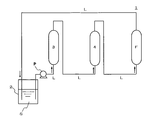
- FIG. 1 shows a configuration example of a pretreatment device for an ion exchange resin according to the present invention.
- a pretreatment apparatus 1 for an ion exchange resin comprises a stock solution tank 2 for storing a non-aqueous solvent, an ion exchange resin container containing an ion exchange resin. 3 and at least a water removing device 4 for removing water in the non-aqueous solvent.
- the ion exchange resin pretreatment apparatus has a circulating liquid delivery pipe for returning the non-aqueous solvent sent from the stock solution tank to the stock solution tank.
- the ion exchange resin pretreatment apparatus 1 As shown in FIG. 1( a ), the ion exchange resin pretreatment apparatus 1 according to the present invention, after passing a nonaqueous solvent from the stock solution tank 2 in this order to the ion exchange resin container 3 and the water removal apparatus 4, A circulating liquid feed pipe L for returning the passed non-aqueous solvent to the stock solution tank 2, or, as illustrated in FIG. 1B, a non-aqueous solvent in the order from the stock solution tank 2 to the water removing device 4 and the ion exchange resin container 3. It has at least one liquid sending pipe selected from a circulating liquid sending pipe L for returning the passed non-aqueous solvent to the stock solution tank 2 after passing the liquid.
- the ion-exchange resin pretreatment apparatus 1 As shown in FIG. 1( c ), the ion-exchange resin pretreatment apparatus 1 according to the present invention, after passing a non-aqueous solvent through a stock solution tank 2 in the order of an ion-exchange resin container 3 and a water removing apparatus 4, Having a circulating liquid feed pipe L1 for returning the passed non-aqueous solvent to the stock solution tank 2, after passing the non-aqueous solvent from the stock solution tank 2 in this order to the water removing device 4 and the ion exchange resin container 3, It may have a circulating liquid sending pipe L2 for returning the above-mentioned non-aqueous solvent to the stock solution tank 2.
- a circulating liquid sending pipe L2 for returning the above-mentioned non-aqueous solvent to the stock solution tank 2.
- the non-aqueous solvent may be an organic non-aqueous solvent.
- the non-aqueous solvent is preferably the same as the non-aqueous solvent in which the ion exchange resin is circulated after pretreatment by the pretreatment device for the ion exchange resin according to the present invention.
- Organic non-aqueous solvents include methanol, ethanol, n-propyl alcohol, isopropyl alcohol (IPA), tert-butyl alcohol, ethylene glycol, diethylene glycol, glycerin, N-methyl-2-pyrrolidone (NMP), dimethyl sulfoxide (DMSO).
- the ion-exchange resin pretreatment apparatus has an ion-exchange resin container containing an ion-exchange resin through which a non-aqueous solvent is passed.
- the ion exchange resin is not particularly limited, but an organic polymer-based ion exchange resin having an organic polymer as a matrix is preferable, and examples of the organic polymer as a matrix include a styrene resin or an acrylic resin. ..
- the styrene-based resin means a resin containing 50% by mass or more of a structural unit derived from styrene or a styrene derivative, which is obtained by homopolymerizing or copolymerizing styrene or a styrene derivative.
- styrene derivative examples include ⁇ -methylstyrene, vinyltoluene, chlorostyrene, ethylstyrene, i-propylstyrene, dimethylstyrene and bromostyrene.
- the styrene-based resin may be a copolymer with another copolymerizable vinyl monomer, as long as it contains styrene or a styrene derivative as a main component or a copolymer.
- examples thereof include divinylbenzene such as o-divinylbenzene, m-divinylbenzene and p-divinylbenzene, alkylene glycol di(meth)acrylate such as ethylene glycol di(meth)acrylate and polyethylene glycol di(meth)acrylate.
- divinylbenzene such as o-divinylbenzene, m-divinylbenzene and p-divinylbenzene
- alkylene glycol di(meth)acrylate such as ethylene glycol di(meth)acrylate and polyethylene glycol di(meth)acrylate.
- ethylene glycol di(meth)acrylate polyethylene glycol di(meth)acrylate having an ethylene polymerization number of 4 to 16 and divinylbenzene are more preferable, and divinylbenzene and ethylene glycol di(meth)acrylate are preferable.
- Acrylate is more preferred, and divinylbenzene is even more preferred.
- an acrylic resin is derived from methacrylic acid, a structural unit derived from acrylic acid, which is obtained by homopolymerizing or copolymerizing one or more selected from acrylic acid, methacrylic acid, acrylic acid ester and methacrylic acid ester. It means a resin containing 50% by mass or more of a structural unit selected from a structural unit, a structural unit derived from acrylate ester and a structural unit derived from methacrylic acid ester.
- acrylic resin more specifically, a homopolymer of acrylic acid, a homopolymer of methacrylic acid, a homopolymer of acrylic acid ester, a homopolymer of methacrylic acid ester, acrylic acid and other monomers (for example, , Acrylic acid ester, methacrylic acid, methacrylic acid ester, copolymer with ⁇ -olefin (eg ethylene, divinylbenzene etc.), methacrylic acid and other monomers (eg acrylic acid, acrylic acid ester, methacrylic acid ester) , Copolymers with ⁇ -olefins (eg ethylene, divinylbenzene etc.), acrylic acid esters and other monomers (eg acrylic acid, methacrylic acid, methacrylic acid esters) ⁇ -olefins (eg ethylene, divinylbenzene etc.) ) Etc.), a copolymer of methacrylic acid ester with another monomer (eg acrylic acid, acrylic acid
- an acrylic acid alkyl ester is preferable, a linear alkyl ester of acrylic acid or a branched alkyl ester is more preferable, and a linear alkyl ester of acrylic acid is further preferable.
- an acrylate alkyl ester in which the alkyl group contained in the alkyl ester moiety has 1 to 4 carbon atoms is more preferred, methyl acrylate and ethyl acrylate are more preferred, and methyl acrylate is particularly preferred.
- a methacrylic acid alkyl ester is preferable, a methacrylic acid linear alkyl ester or a branched alkyl ester is more preferable, and a methacrylic acid linear alkyl ester is further preferable.
- a methacrylic acid alkyl ester in which the alkyl group contained in the alkyl ester moiety has 1 to 4 carbon atoms is more preferable, methyl methacrylate and ethyl methacrylate are more preferable, and methyl methacrylate is particularly preferable.
- the above-mentioned ion exchange resin may include one or more selected from a cation exchange resin having a cation exchange group, an anion exchange resin having an anion exchange group, and a chelate resin.
- the cation exchange resin examples include strong acidic resins having a sulfo group as a cation exchange group and weak acidic resins having a carboxy group as a cation exchange group.
- the anion exchange resin examples include strong basic ones having a quaternary ammonium group as an anion exchange group and weak basic ones having an amino group as an anion exchange group.
- a weakly basic ion-exchange resin is preferable as the ion-exchange resin contained in the ion-exchange resin container for passing the non-aqueous solvent.
- the weakly basic ion-exchange group constituting the weakly basic ion-exchange resin is preferably a primary to tertiary amino group, and more preferably a tertiary amino group such as dimethylamino group.
- R 1 group and R 2 group are hydrocarbon groups having 1 to 3 carbon atoms and may be the same or different from each other, and * is a bond with a base or a bonding group for bonding to a base. The part is shown.
- the R 1 group and the R 2 group are hydrocarbon groups having 1 to 3 carbon atoms.
- the R 1 group or R 2 group one or more selected from an alkyl group and an alkenyl group can be mentioned, and an alkyl group is preferable.
- Specific examples of the R 1 group or R 2 group include one or more selected from a methyl group, an ethyl group, a propyl group, and a propylene group, and a methyl group is preferable.
- the R 1 group and the R 2 group may be the same or different from each other.
- Examples of the weakly basic anion exchange group represented by the above general formula (I) include a dimethylamino group, a diethylamino group, a dipropylamino group and the like, and a dimethylamino group is preferable.
- * represents a binding site between the weakly basic anion exchange group represented by the above general formula (I) and the base or the bonding group for binding to the base.
- the weakly basic anion-exchange group represented by the general formula (I) is appropriately bonded to a substrate made of a styrene-based resin via an R 3 group which is a bonding group, as shown in the following general formula (II). It is preferably bound.
- the R 1 group and the R 2 group are hydrocarbon groups having 1 to 3 carbon atoms and may be the same or different, and the R 3 group is a hydrocarbon group having 1 to 3 carbon atoms. , * Indicates the binding site with the substrate.
- the R 1 group and the R 2 group include the same ones as described above.
- the R 3 group is a hydrocarbon group having 1 to 3 carbon atoms, and as the R 3 group, one or more selected from an alkylene group and an alkenylene group can be exemplified, and an alkylene group is preferable.
- Specific examples of the R 3 group include one or more selected from a methylene group (—CH 2 —), an ethylene group (—CH 2 CH 2 —), a propylene group (—CH 2 CH 2 CH 2 —), and the like. And a methylene group is preferred.
- the weakly basic anion exchange group represented by the above general formula (I) can be introduced into the styrene resin by introducing it into styrene or a styrene derivative as a substituent.
- Such anion exchange resin may be a commercially available product, and examples thereof include one or more selected from DIAION WA30 manufactured by Mitsubishi Chemical Corporation, ORLITE DS-6 manufactured by Organo Corporation, and the like.
- the ion exchange resin contained in the ion exchange resin container may have a gel type structure, a macroreticular type (MR type) structure, or a macroporous type ( It may have a (MP type) structure or a porous type structure.
- MR type macroreticular type
- MP type macroporous type
- the size of the ion exchange resin contained in the above ion exchange resin container is not particularly limited, but its harmonic mean diameter is preferably 300 to 1000 ⁇ m, more preferably 400 to 800 ⁇ m, and more preferably 500 to 700 ⁇ m. More preferred are:
- the ion exchange resin contained in the ion exchange resin container preferably has a total ion exchange capacity in the wet state of 0.1 to 3.0 (eq/LR), It is more preferably from 2.5 to 2.5 (eq/LR), even more preferably from 1.0 to 2.0 (eq/LR).
- the accommodation form of the ion exchange resin accommodated in the ion exchange resin container is not particularly limited as long as the nonaqueous solvent and the ion exchange resin can contact each other.
- the ion exchange resin container may be a column or tank filled with an ion exchange resin capable of passing a non-aqueous solvent.
- the ion exchange resin container may be equipped with a pump for passing a non-aqueous solvent.
- the liquid-passing speed (liquid space velocity) of passing the non-aqueous solvent through the ion-exchange resin in the ion-exchange resin container is such that water in the ion-exchange resin is removed and reduced. It may be appropriately selected from the possible speeds.
- the ion-exchange resin pretreatment device is a circulating liquid-feeding device such that the non-aqueous solvent flowing in the circulating liquid-feeding pipe flows in an upward flow with respect to the ion-exchange resin contained in the ion-exchange resin container.
- the tubes are preferably arranged.
- the ion exchange resin pretreatment apparatus 1 is supplied from a stock solution tank 2 that stores a non-aqueous solvent, and the circulating non-aqueous solvent S is ion-exchanged. It is preferable that the circulating liquid feeding pipe L is arranged so as to pass the ion exchange resin housed in the resin container 3 in an upward flow.
- the circulation liquid-feeding pipe L is arranged so that the non-aqueous solvent flowing in the circulation liquid-feeding pipe passes through the ion-exchange resin contained in the ion-exchange resin container in an upward flow.
- the air bubbles in the ion exchange resin are removed. It can be removed by circulating while degassing. Therefore, even when air bubbles or the like are mixed in the ion exchange resin housed in the ion exchange resin container, while maintaining good contact between the non-aqueous solvent and the ion exchange resin, Water can be removed and reduced.
- the ion exchange resin pretreatment apparatus has a water removing apparatus for removing water in the non-aqueous solvent.
- the water removal device examples include a water adsorption device, a membrane separation device, and a gas-liquid separation device, and the water adsorption device is preferable.
- the water adsorption device preferably contains zeolite as a water adsorption material.
- the zeolite accommodated in the water adsorption device is not particularly limited as long as it can adsorb the water in the non-aqueous solvent, and one or more selected from crystalline zeolites can be mentioned.
- the crystalline zeolite include one or more crystalline zeolites selected from A type, Y type, X type, chabazite, ferrierite, ZSM-5, clinoptilolite and the like.
- the crystalline zeolite has a Si/Al molar ratio of 1 to 5 constituting the crystalline zeolite.
- Si/Al molar ratio is within the above range, it is structurally stable, has an appropriate cation content, and can suitably adsorb and remove water.
- the above crystalline zeolite may or may not have the cations exchanged with lithium ions, calcium ions, or the like.
- the crystalline zeolite preferably has a pore diameter of 3 ⁇ to 10 ⁇ , more preferably 3 ⁇ to 6 ⁇ , and even more preferably 3 ⁇ to 5 ⁇ .
- the pore size means a theoretical value estimated from the crystal structure and the cation species retained.
- the crystalline zeolite is preferably spherical or columnar, and preferably has a diameter of 0.5 to 5 mm.
- the nonaqueous solvent can be suitably impregnated without lowering the handling property.
- the accommodation form of zeolite contained in the water adsorption device is not particularly limited as long as the nonaqueous solvent and the zeolite can come into contact with each other.
- the water adsorption device may be a column or tank filled with zeolite capable of passing a non-aqueous solvent.
- the water adsorption device may be provided with a pump for passing a non-aqueous solvent.
- the liquid-passing speed (liquid space velocity) for passing the non-aqueous solvent through the zeolite may be appropriately selected from the speed at which water in the ion-exchange resin can be removed.
- the ion-exchange resin pretreatment device according to the present invention is arranged such that the non-aqueous solvent flowing in the circulating liquid-feeding pipe flows upward in the zeolite stored in the water adsorption device. Is preferably provided.
- the ion-exchange resin pretreatment apparatus 1 with respect to the zeolite accommodated in the water removal apparatus 4, the non-water flowing through the circulation liquid feeding pipe L. It is preferable that the circulation liquid-feeding pipe L is arranged so that the solvent flows in an upward flow.
- the circulation liquid transfer pipe L is arranged so that the non-aqueous solvent flowing in the circulation liquid transfer pipe flows upwardly with respect to the zeolite accommodated in the water adsorption device. Even when bubbles and the like are mixed in the zeolite contained in the device, the non-aqueous solvent is circulated while degassing the bubbles in the zeolite when the non-aqueous solvent flows upward in the water adsorption device. Can be removed. Therefore, even when bubbles or the like are mixed in the zeolite contained in the water adsorption device, the treatment can be performed while maintaining the contact property between the non-aqueous solvent and the zeolite suitable.
- the circulating liquid feeding pipe L is made of non-water in the order from the stock solution tank 2 to the ion exchange resin container 3 and the water removing apparatus 4.
- the passed non-aqueous solvent S is returned to the stock solution tank 2 so that the non-aqueous solvent S can be continuously circulated (FIG. 2) or the stock solution tank 2
- the passed nonaqueous solvent is returned to the stock solution tank so that the nonaqueous solvent S can be continuously circulated. It is located (Fig. 3).
- the circulation liquid delivery pipe is arranged so that the non-aqueous solvent in the stock solution tank can be circulated in the ion exchange resin container and the water removal apparatus.
- the ion exchange resin can be pretreated while repeating the elution of the water remaining in the ion exchange resin with the non-aqueous solvent and the adsorption removal of the water eluted in the non-aqueous solvent with the water removing device. Therefore, in the ion-exchange resin pretreatment apparatus according to the present invention, the amount of water contained in the ion-exchange resin can be simply and economically increased simply by circulating a small amount of the non-aqueous solvent in the flow path of the circulating liquid feeding pipe. It can be reduced.
- the pretreatment device for the ion exchange resin according to the present invention may further have a filtration device at the subsequent stage (downstream side) of the water removal device.
- the amount of the non-aqueous solvent used for the ion-exchange resin pretreatment is 1 to 30 times the volume of the ion-exchange resin unit volume in the ion-exchange resin container.
- the volume is preferably 1 to 20 times, more preferably 1 to 10 times.
- the circulation amount of the non-aqueous solvent flowing in the circulation liquid feeding pipe may be appropriately selected from the circulation amount that reduces the adsorbed water content of the ion-exchange resin to a desired degree.
- the non-aqueous solvent to be treated is preferably treated with SV (flow rate/ion exchange resin volume ratio) of 1 to 100 hr -1 , more preferably SV2.
- the treatment can be performed by passing the solution at ⁇ 50 hr ⁇ 1 , and more preferably at SV 5 to 20 hr ⁇ 1 .
- an ion exchange resin pretreatment device capable of easily and economically reducing the water content.
- the pretreatment method of an ion exchange resin according to the present invention is an ion exchange having at least a stock solution tank for storing a non-aqueous solvent, an ion exchange resin container containing an ion exchange resin, and a water removing device for removing water in the non-aqueous solvent.
- a solution transfer for returning the passed non-aqueous solvent to the stock solution tank, and From the stock solution tank, after passing a non-aqueous solvent in the order of the water removal device and the ion exchange resin container, one or more liquids selected from the liquids returned to the stock solution tank. It is characterized in that it is carried out while circulating a non-aqueous solvent.
- the pretreatment method for an ion exchange resin according to the present invention substantially relates to a method for pretreating an ion exchange resin using the pretreatment apparatus for an ion exchange resin according to the present invention, and details of the treatment method. Is common to the above description of the usage pattern of the pretreatment apparatus for an ion exchange resin according to the present invention.
- the water content (mass ppm) in the organic non-aqueous solvent before the treatment and the water content (mass ppm) in the organic non-aqueous solvent after the treatment were values measured by the Karl Fischer method.
- Means The amount of Al (mass ppb) in the organic non-aqueous solvent means a value measured by inductively coupled plasma mass spectrometry (ICP-MS), and the amount of Al in the organic non-aqueous solvent is measured by a water removing device. It corresponds to the amount of zeolite that has flowed out.
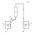
- Example 1 Pretreatment of the ion exchange resin in the ion exchange resin container 3 was performed using the ion exchange resin pretreatment apparatus 1 shown in FIG. That is, as shown in FIG. 2, an organic non-aqueous solvent S (water content less than 10 mass ppm) prepared by mixing ethylene carbonate and dimethyl carbonate stored in the stock solution tank 2 in a volume ratio of 1:1 was used as a weak base.
- an organic non-aqueous solvent S water content less than 10 mass ppm
- a cationic anion exchange resin MR type anion exchange resin having a styrene resin as a base material and a dimethylamino group as a weakly basic anion exchange group.
- the liquid was passed from the bottom to the top in an upward flow at a liquid flow rate of 5 (L/L-zeolite)/h
- the discharged organic non-aqueous solvent was returned to the stock solution tank 2.
- the above treatment was continued for 10 hours and the organic non-aqueous solvent was circulated in the pretreatment apparatus 1
- the water content in the organic non-aqueous solvent flowing out from the ion exchange resin container 3 was measured to be 10 mass ppm. Was less than.
- the amount of Al in the organic non-aqueous solvent collected from the stock solution tank 2 was measured, it was 16 mass ppb.
- the volume of the organic non-aqueous solvent S used was 10 times the unit volume of the ion exchange resin.
- Example 2 In Example 1, except that water was added to the organic non-aqueous solvent before the treatment by the pretreatment apparatus 1 for the ion exchange resin, and the organic non-aqueous solvent S having a water content of 20 mass ppm was used, the same as in Example 1. Was pretreated with an ion exchange resin. The water content in the organic non-aqueous solvent flowing out from the ion exchange resin container 3 was measured and found to be less than 10 mass ppm. The volume of the organic non-aqueous solvent S used was 10 times the unit volume of the ion exchange resin.
- Example 3 The ion exchange resin in the ion exchange resin container 3 was pretreated by using the ion exchange resin pretreatment apparatus 1 shown in FIG. That is, as shown in FIG. 4, an organic non-aqueous solvent S (water content less than 10 mass ppm) prepared by mixing ethylene carbonate and dimethyl carbonate stored in the stock solution tank 2 in a volume ratio of 1:1 was used as a weak base. Pump P from the bottom to the top of an ion exchange resin container 3 containing a cationic anion exchange resin (MR type anion exchange resin having a styrene resin as a base material and a dimethylamino group as a weakly basic anion exchange group).
- MR type anion exchange resin having a styrene resin as a base material and a dimethylamino group as a weakly basic anion exchange group.
- the liquid was passed in an upward flow at a filtration rate of 0.53 ml/(h ⁇ cm 2 ), and the organic non-aqueous solvent that flowed out was returned to the stock solution tank 2.
- the water content in the organic non-aqueous solvent flowing out from the ion exchange resin container 3 was measured to be 10 mass ppm. Was less than.
- the amount of Al in the organic non-aqueous solvent collected from the stock solution tank 2 was measured, it was 3 mass ppb.
- the volume of the organic non-aqueous solvent S used was 10 times the unit volume of the ion exchange resin.
- Comparative example 2 In Comparative Example 1, the pretreatment of the ion exchange resin was performed in the same manner as in Comparative Example 1 except that the organic non-aqueous solvent S having a volume 100 times the unit volume of the ion exchange resin was used. The water content in the organic non-aqueous solvent flowing out from the ion exchange resin container 3 was measured and found to be less than 10 mass ppm.
- Comparative example 3 In Comparative Example 2, the same as Comparative Example 2 except that water was added to the organic non-aqueous solvent before the treatment by the ion-exchange resin pretreatment device 11 and the organic non-aqueous solvent S having a moisture content of 20 mass ppm was used. Then, the ion exchange resin was pretreated. The water content in the organic non-aqueous solvent flowing out of the ion exchange resin container 3 was measured and found to be 20 mass ppm. The volume of the organic non-aqueous solvent S used was 100 times the unit volume of the ion exchange resin.
- Table 1 shows the results of the above examples and comparative examples.
- Example 3 in the pretreatment apparatus 1 for the ion exchange resin, the organic non-aqueous solvent S was passed from the stock solution tank 2 in the order of the ion exchange resin container 3 and the water removal apparatus 4. After that, the passed non-aqueous solvent is returned to the undiluted solution tank 2 and is circulated, so that the water content of the ion exchange resin contained in the ion exchange resin container 3 is highly reduced in a simple and economical manner. You know you will get.
- Example 3 since the filtering apparatus F is further provided on the downstream side of the water removing apparatus, compared with the pretreatment apparatus 1 of Example 1 which does not have the filtering apparatus F, the organic non-aqueous solvent is used. It can be seen that the amount of Al is reduced and the mixture of zeolite particles into the ion exchange resin container can be suppressed.
- the pretreatment device 11 for the ion exchange resin does not have the circulating liquid delivery pipe L for returning the treatment liquid to the water removal device 4 or the stock solution tank 2, and the organic non-aqueous solvent is not used. Since it is not used by being circulated, it is understood that the water content of the ion exchange resin cannot be sufficiently reduced even if the same amount of the non-aqueous solvent is used.
- the pretreatment device 11 for the ion-exchange resin does not have the circulating liquid delivery pipe L for returning the treatment liquid to the water removal device 4 or the stock solution tank 2, and the organic nonaqueous solvent is not used. Since it is not circulated and used, in order to reduce the water content of the organic non-aqueous solvent flowing out from the ion exchange resin to a level equivalent to that in Example 1, 10 times the amount of organic solvent compared to Example 1 was used. It can be seen that a non-aqueous solvent is needed.
- the pretreatment device 11 for the ion exchange resin does not have the circulating liquid feed pipe L for returning the treatment liquid to the water removal device 4 or the stock solution tank 2, and the organic non-aqueous solvent is not used.
- the amount of water in the organic non-aqueous solvent before treatment is as high as 20 mass ppm, it is not used in a circulating manner, so that 10 times the amount of the organic non-aqueous solvent is used as compared with Example 1. Also, it is understood that the water content of the ion exchange resin cannot be sufficiently reduced.
- an ion exchange resin pretreatment device and an ion exchange resin pretreatment method capable of easily and economically reducing the water content.
- Ion exchange resin pretreatment device 1
- Stock solution tank 3
- Ion exchange resin container 4
- Moisture removal device 5 Storage tank
Landscapes
- Chemical & Material Sciences (AREA)
- Chemical Kinetics & Catalysis (AREA)
- Organic Chemistry (AREA)
- General Chemical & Material Sciences (AREA)
- Engineering & Computer Science (AREA)
- Manufacturing & Machinery (AREA)
- Electrochemistry (AREA)
- Inorganic Chemistry (AREA)
- Physics & Mathematics (AREA)
- Condensed Matter Physics & Semiconductors (AREA)
- General Physics & Mathematics (AREA)
- Analytical Chemistry (AREA)
- Treatment Of Water By Ion Exchange (AREA)
- Treatment Of Liquids With Adsorbents In General (AREA)
- Secondary Cells (AREA)
- Processes Of Treating Macromolecular Substances (AREA)
Abstract
簡便かつ経済的に含有水分量を低減可能なイオン交換樹脂の前処理装置を提供する。 非水溶媒を貯蔵する原液タンク、イオン交換樹脂を収容したイオン交換樹脂容器および非水溶媒中の水分を除去する水分除去装置を少なくとも有するとともに、前記原液タンクから、前記イオン交換樹脂容器および前記水分除去装置の順に非水溶媒を通液した後、通液した非水溶媒を前記原液タンクに返送する循環送液管並びに前記原液タンクから、前記水分除去装置および前記イオン交換樹脂容器の順に非水溶媒を通液した後、通液した非水溶媒を前記原液タンクに返送する循環送液管から選ばれる少なくとも一つの送液管を有することを特徴とするイオン交換樹脂の前処理装置である。
Description
本発明は、イオン交換樹脂の前処理装置およびイオン交換樹脂の前処理方法に関するものである。
近年、半導体製造工程やリチウムイオン電池の電解液等として、不純物が高度に除去され、精製された非水溶媒が用いられるようになっている。
非水溶媒の精製方法としては、不純物を蒸留除去する蒸留法が知られているが、設備費用負担が大きく、蒸留処理に多大なエネルギーを要するばかりか、高度な精製を行い難い等の技術課題が存在していた。
そこで、近年では、イオン交換樹脂やイオン交換フィルターを用いたイオン交換法により非水溶媒を精製する方法が提案されるようになっている。イオン交換法によれば、設備費用負担が小さく、省エネルギーで、不純物を高度に精製除去し得るとされている。
例えば、リチウムイオン電池の電解液は、フッ素系のリチウム塩等の電解質を非水溶媒に溶解して製造される。
電解液では、酸(主にフッ化水素)が不純物となるために、これをイオン交換樹脂で除去する精製方法が検討されているが、同時に水分も不純物となるため、イオン交換樹脂の含有水分を電解液中へ溶出させないように、イオン交換樹脂の含有水分を低減する前処理が必要になる。
上記イオン交換樹脂の含有水分を低減する方法としては、イオン交換樹脂を減圧乾燥する方法や、減圧乾燥に加えてイオン交換樹脂に非水溶媒を通液して除去する方法が知られている(例えば、特許文献1(特表2000-505042号公報)参照)。
電解液では、酸(主にフッ化水素)が不純物となるために、これをイオン交換樹脂で除去する精製方法が検討されているが、同時に水分も不純物となるため、イオン交換樹脂の含有水分を電解液中へ溶出させないように、イオン交換樹脂の含有水分を低減する前処理が必要になる。
上記イオン交換樹脂の含有水分を低減する方法としては、イオン交換樹脂を減圧乾燥する方法や、減圧乾燥に加えてイオン交換樹脂に非水溶媒を通液して除去する方法が知られている(例えば、特許文献1(特表2000-505042号公報)参照)。
しかしながら、本発明者等が検討したところ、減圧乾燥ではイオン交換樹脂の含有水分を十分に低減することができず、減圧乾燥に加えて非水溶媒を通液する方法でも、イオン交換樹脂に対して数十倍~数百倍量もの多量の非水溶媒が必要になることが判明した。
このような状況下、本発明は、簡便かつ経済的に含有水分量を低減可能なイオン交換樹脂の前処理装置およびイオン交換樹脂の前処理方法を提供することを目的とするものである。
本発明者等は、上記目的を達成するために鋭意研究を重ねた結果、非水溶媒を貯蔵する原液タンク、イオン交換樹脂を収容したイオン交換樹脂容器および非水溶媒中の水分を除去する水分除去装置を少なくとも有するとともに、前記原液タンクから、前記イオン交換樹脂容器および前記水分除去装置の順に非水溶媒を通液した後、通液した非水溶媒を前記原液タンクに返送する循環送液管並びに前記原液タンクから、前記水分除去装置および前記イオン交換樹脂容器の順に非水溶媒を通液した後、通液した非水溶媒を前記原液タンクに返送する循環送液管から選ばれる少なくとも一つの送液管を有するイオン交換樹脂の前処理装置により、上記技術課題を解決し得ることを見出し、本知見に基づいて本発明を完成するに至った。
すなわち、本発明は、
(1)非水溶媒を貯蔵する原液タンク、イオン交換樹脂を収容したイオン交換樹脂容器および非水溶媒中の水分を除去する水分除去装置を少なくとも有するとともに、
前記原液タンクから、前記イオン交換樹脂容器および前記水分除去装置の順に非水溶媒を通液した後、通液した非水溶媒を前記原液タンクに返送する循環送液管並びに
前記原液タンクから、前記水分除去装置および前記イオン交換樹脂容器の順に非水溶媒を通液した後、通液した非水溶媒を前記原液タンクに返送する循環送液管から選ばれる少なくとも一つの送液管を有する
ことを特徴とするイオン交換樹脂の前処理装置、
(2)前記水分除去装置が水分吸着装置である上記(1)に記載のイオン交換樹脂の前処理装置、
(3)前記水分吸着装置が水分吸着材としてゼオライトを収容したものである上記(2)に記載のイオン交換樹脂の前処理装置、
(4)前記水分吸着装置に収容されたゼオライトに対し、前記循環送液管内を流通する非水溶媒が上向流で通液するように前記循環送液管が配置されている上記(3)に記載のイオン交換樹脂の前処理装置、
(5)前記水分除去装置の下流側にさらに濾過装置を有する上記(1)~(4)のいずれかに記載のイオン交換樹脂の前処理装置、
(6)前記イオン交換樹脂が陰イオン交換樹脂である上記(1)~(5)のいずれかに記載のイオン交換樹脂の前処理装置、
(7)前記イオン交換樹脂が弱塩基性陰イオン交換樹脂である上記(1)~(6)のいずれかに記載のイオン交換樹脂の前処理装置、
(8)非水溶媒を貯蔵する原液タンク、イオン交換樹脂を収容したイオン交換樹脂容器および非水溶媒中の水分を除去する水分除去装置を少なくとも有するイオン交換樹脂の前処理装置に対し、
前記原液タンクから、前記イオン交換樹脂容器および前記水分除去装置の順に非水溶媒を通液した後、通液した非水溶媒を前記原液タンクに返送する送液並びに
前記原液タンクから、前記水分除去装置および前記イオン交換樹脂容器の順に非水溶媒を通液した後、通液した非水溶媒を前記原液タンクに返送する送液から選ばれる一種以上の送液を非水溶媒を循環しながら行う
ことを特徴とするイオン交換樹脂の前処理方法、
を提供するものである。
本発明によれば、簡便かつ経済的に含有水分量を低減可能なイオン交換樹脂の前処理装置およびイオン交換樹脂の前処理方法を提供することができる。
本発明に係るイオン交換樹脂の前処理装置は、非水溶媒を貯蔵する原液タンク、イオン交換樹脂を収容したイオン交換樹脂容器および非水溶媒中の水分を除去する水分除去装置を少なくとも有するとともに、前記原液タンクから、前記イオン交換樹脂容器および前記水分除去装置の順に非水溶媒を通液した後、通液した非水溶媒を前記原液タンクに返送する循環送液管並びに前記原液タンクから、前記水分除去装置および前記イオン交換樹脂容器の順に非水溶媒を通液した後、通液した非水溶媒を前記原液タンクに返送する循環送液管から選ばれる少なくとも一つの送液管を有することを特徴とするものである。
以下、本発明に係るイオン交換樹脂の前処理装置について、適宜、図面を例示しつつ説明するものとする。
図1は、本発明に係るイオン交換樹脂の前処理装置の構成例を示すものである。
図1(a)~図1(c)に示すように、本発明に係るイオン交換樹脂の前処理装置1は、非水溶媒を貯蔵する原液タンク2、イオン交換樹脂を収容したイオン交換樹脂容器3および非水溶媒中の水分を除去する水分除去装置4を少なくとも有している。
本発明に係るイオン交換樹脂の前処理装置は、原液タンクから送出した非水溶媒を原液タンクに返送する循環送液管を有している。
本発明に係るイオン交換樹脂の前処理装置1は、図1(a)に例示するように、原液タンク2からイオン交換樹脂容器3および水分除去装置4の順に非水溶媒を通液した後、通液した非水溶媒を原液タンク2に返送する循環送液管Lか、図1(b)に例示するように、原液タンク2から水分除去装置4およびイオン交換樹脂容器3の順に非水溶媒を通液した後、通液した非水溶媒を原液タンク2に返送する循環送液管Lから選ばれる少なくとも一つの送液管を有している。
本発明に係るイオン交換樹脂の前処理装置1は、図1(c)に例示するように、原液タンク2からイオン交換樹脂容器3および水分除去装置4の順に非水溶媒を通液した後、通液した非水溶媒を原液タンク2に返送する循環送液管L1を有するとともに、原液タンク2から、水分除去装置4およびイオン交換樹脂容器3の順に非水溶媒を通液した後、通液した非水溶媒を原液タンク2に返送する循環送液管L2を有するものであってもよい。
図1(c)に例示する態様においては、非水溶媒の通液時に、循環送液管L1または循環送液管L2に設けられたいずれか一方の送液管のバルブを閉じることにより、他方の送液管内を通液させることになる。
図1(c)に例示する態様においては、非水溶媒の通液時に、循環送液管L1または循環送液管L2に設けられたいずれか一方の送液管のバルブを閉じることにより、他方の送液管内を通液させることになる。
本発明に係るイオン交換樹脂の前処理装置において、非水溶媒としては有機非水溶媒を挙げることができる。
非水溶媒としては、本発明に係るイオン交換樹脂の前処理装置による前処理後にイオン交換樹脂を流通させる非水溶媒と同一のものであることが好ましい。
有機非水溶媒としては、メタノール、エタノール、n-プロピルアルコール、イソプロピルアルコール(IPA)、tert-ブチルアルコール、エチレングリコール、ジエチレングリコール、グリセリン、N-メチル-2-ピロリドン(NMP)、ジメチルスルホキシド(DMSO)、プロピレングリコールモノメチルエーテル(PGME)、プロピレングリコールモノメチルエーテルアセテート(PGMEA)、ブチルカルビトール(BDG)、モノエタノールアミン(MEA)、乳酸メチル、乳酸エチル、酢酸エチル、酢酸ブチル、酢酸イソアミル、アセトン、メチルエチルケトン(MEK)、メチルイソブチルケトン(MIBK)、トルエン、キシレン、シクロヘキサン、エチレンカーボネート、プロピレンカーボネート、ジメチルカーボネート、ジエチルカーボネート、メチルエチルカーボネート、γ-ブチロラクトン、スルホラン、1,2-ジメトキシエタン、1,2-ジエトキシエタン、1,2-ジブトキシエタン、エトキシメトキシエタン等から選ばれる一種以上を挙げることができる。
本発明に係るイオン交換樹脂の前処理装置は、非水溶媒を通液するイオン交換樹脂を収容したイオン交換樹脂容器を有している。
イオン交換樹脂としては、特に制限されないが、有機高分子を母体とする有機高分子系のイオン交換樹脂が好ましく、母体となる有機高分子としては、スチレン系樹脂またはアクリル系樹脂を挙げることができる。
本出願書類において、スチレン系樹脂とは、スチレン又はスチレン誘導体を単独または共重合した、スチレン又はスチレン誘導体に由来する構成単位を50質量%以上含む樹脂を意味する。
上記スチレン誘導体としては、α-メチルスチレン、ビニルトルエン、クロロスチレン、エチルスチレン、i-プロピルスチレン、ジメチルスチレン、ブロモスチレン等が挙げられる。
スチレン系樹脂としては、スチレンまたはスチレン誘導体の単独または共重合体を主成分とするものであれば、共重合可能な他のビニルモノマーとの共重合体であってもよく、このようなビニルモノマーとしては、例えば、o-ジビニルベンゼン、m-ジビニルベンゼン、p-ジビニルベンゼン等のジビニルベンゼン、エチレングリコールジ(メタ)アクリレート、ポリエチレングリコールジ(メタ)アクリレート等のアルキレングリコールジ(メタ)アクリレート等の多官能性モノマーや、(メタ)アクリロニトリル、メチル(メタ)アクリレート等から選ばれる一種以上を挙げることができる。
上記共重合可能な他のビニルモノマーとしては、エチレングリコールジ(メタ)アクリレート、エチレン重合数が4~16のポリエチレングリコールジ(メタ)アクリレート、ジビニルベンゼンがより好ましく、ジビニルベンゼン、エチレングリコールジ(メタ)アクリレートがより好ましく、ジビニルベンゼンがさらに好ましい。
本出願書類において、アクリル系樹脂とは、アクリル酸、メタクリル酸、アクリル酸エステルおよびメタクリル酸エステルから選ばれる一種以上を単独重合または共重合した、アクリル酸に由来する構成単位、メタクリル酸に由来する構成単位、アクリル酸エステルに由来する構成単位およびメタクリル酸エステルに由来する構成単位から選ばれる構成単位を50質量%以上含む樹脂を意味する。
上記アクリル系樹脂として、より具体的には、アクリル酸の単独重合体、メタクリル酸の単独重合体、アクリル酸エステルの単独重合体、メタクリル酸エステルの単独重合体、アクリル酸と他のモノマー(例えば、アクリル酸エステル、メタクリル酸、メタクリル酸エステル、α-オレフィン(例えばエチレン、ジビニルベンゼン等)等)との共重合体、メタクリル酸と他のモノマー(例えば、アクリル酸、アクリル酸エステル、メタクリル酸エステル、α-オレフィン(例えばエチレン、ジビニルベンゼン等)等)との共重合体、アクリル酸エステルと他のモノマー(例えば、アクリル酸、メタクリル酸、メタクリル酸エステル、α-オレフィン(例えばエチレン、ジビニルベンゼン等)等)との共重合体、メタクリル酸エステルと他のモノマー(例えば、アクリル酸、アクリル酸エステル、メタクリル酸、α-オレフィン(例えばエチレン、ジビニルベンゼン等))との共重合体から選ばれる一種以上を挙げることができ、これ等のうち、メタクリル酸・ジビニルベンゼン共重合体またはアクリル酸・ジビニルベンゼン共重合体が好ましい。
アクリル酸エステルとしては、アクリル酸アルキルエステルが好ましく、アクリル酸の直鎖アルキルエステル又は分岐鎖アルキルエステルがより好ましく、アクリル酸の直鎖アルキルエステルが更に好ましい。
アクリル酸エステルとしては、アルキルエステルの部位に含まれるアルキル基の炭素数が1~4であるアクリル酸アルキルエステルが更に好ましく、アクリル酸メチル、アクリル酸エチルが更に好ましく、アクリル酸メチルが特に好ましい。
アクリル酸エステルとしては、アルキルエステルの部位に含まれるアルキル基の炭素数が1~4であるアクリル酸アルキルエステルが更に好ましく、アクリル酸メチル、アクリル酸エチルが更に好ましく、アクリル酸メチルが特に好ましい。
メタクリル酸エステルとしては、メタクリル酸アルキルエステルが好ましく、メタクリル酸の直鎖アルキルエステル又は分岐鎖アルキルエステルがより好ましく、メタクリル酸の直鎖アルキルエステルが更に好ましい。
メタクリル酸エステルとしては、アルキルエステルの部位に含まれるアルキル基の炭素数が1~4であるメタクリル酸アルキルエステルがより好ましく、メタクリル酸メチル、メタクリル酸エチルが更に好ましく、メタクリル酸メチルが特に好ましい。
メタクリル酸エステルとしては、アルキルエステルの部位に含まれるアルキル基の炭素数が1~4であるメタクリル酸アルキルエステルがより好ましく、メタクリル酸メチル、メタクリル酸エチルが更に好ましく、メタクリル酸メチルが特に好ましい。
上記イオン交換樹脂としては、陽イオン交換基を有する陽イオン交換樹脂、陰イオン交換基を有する陰イオン交換樹脂およびキレート樹脂から選ばれる一種以上を挙げることができる。
上記陽イオン交換樹脂としては、陽イオン交換基としてスルホ基を有する強酸性のものや、陽イオン交換基としてカルボキシ基を有する弱酸性のものを挙げることができる。
上記陰イオン交換樹脂としては、陰イオン交換基として四級アンモニウム基を有する強塩基性のものや、陰イオン交換基としてアミノ基を有する弱塩基性のものを挙げることができる。
本発明に係るイオン交換樹脂の前処理装置において、イオン交換樹脂容器に収容する非水溶媒を通液するイオン交換樹脂としては、弱塩基性イオン交換樹脂が好ましい。
上記陰イオン交換樹脂としては、陰イオン交換基として四級アンモニウム基を有する強塩基性のものや、陰イオン交換基としてアミノ基を有する弱塩基性のものを挙げることができる。
本発明に係るイオン交換樹脂の前処理装置において、イオン交換樹脂容器に収容する非水溶媒を通液するイオン交換樹脂としては、弱塩基性イオン交換樹脂が好ましい。
弱塩基性イオン交換樹脂を構成する弱塩基性のイオン交換基としては、一級~三級のアミノ基であることが好ましく、ジメチルアミノ基等の三級アミノ基であることがより好ましい。
弱塩基性陰イオン交換基としては、下記一般式(I)

(ただし、R1基およびR2基は炭素数1~3の炭化水素基であって互いに同一であっても異なっていてもよく、*は基体または基体へ結合するための結合基との結合部位を示す。)
で表される三級アミノ基を挙げることができる。
で表される三級アミノ基を挙げることができる。
上記一般式(I)で表される弱塩基性陰イオン交換基において、R1基およびR2基は炭素数1~3の炭化水素基である。
R1基またはR2基としては、アルキル基およびアルケニル基から選ばれる一種以上を挙げることができ、アルキル基であることが好ましい。
R1基またはR2基として、具体的には、メチル基、エチル基、プロピル基およびプロピレン基から選ばれる一種以上を挙げることができ、メチル基であることが好ましい。
上記一般式(I)で表される弱塩基性陰イオン交換基において、R1基およびR2基は、互いに同一であっても異なっていてもよい。
R1基またはR2基としては、アルキル基およびアルケニル基から選ばれる一種以上を挙げることができ、アルキル基であることが好ましい。
R1基またはR2基として、具体的には、メチル基、エチル基、プロピル基およびプロピレン基から選ばれる一種以上を挙げることができ、メチル基であることが好ましい。
上記一般式(I)で表される弱塩基性陰イオン交換基において、R1基およびR2基は、互いに同一であっても異なっていてもよい。
上記一般式(I)で表される弱塩基性陰イオン交換基としては、ジメチルアミノ基、ジエチルアミノ基、ジプロピルアミノ基等を挙げることができ、ジメチルアミノ基であることが好ましい。
上記一般式(I)において、*は、上記一般式(I)で表される弱塩基性陰イオン交換基と、基体または基体へ結合するための結合基との結合部位を示す。
上記一般式(I)で表される弱塩基性陰イオン交換基は、スチレン系樹脂からなる基体に対し、下記一般式(II)に示すように、適宜結合基であるR3基を介して結合していることが好ましい。

(ただし、R1基およびR2基は炭素数1~3の炭化水素基であって互いに同一であっても異なっていてもよく、R3基は炭素数1~3の炭化水素基であり、*は基体との結合部位を示す。)
上記R1基およびR2基としては、上述したものと同様のものを挙げることができる。
上記R3基は炭素数1~3の炭化水素基であり、R3基としては、アルキレン基およびアルケニレン基から選ばれる一種以上を挙げることができ、アルキレン基であることが好ましい。
R3基として、具体的には、メチレン基 (-CH2-)、エチレン基(-CH2CH2-)、 プロピレン基(-CH2CH2CH2-)等から選ばれる一種以上を挙げることができ、メチレン基が好ましい。
上記R3基は炭素数1~3の炭化水素基であり、R3基としては、アルキレン基およびアルケニレン基から選ばれる一種以上を挙げることができ、アルキレン基であることが好ましい。
R3基として、具体的には、メチレン基 (-CH2-)、エチレン基(-CH2CH2-)、 プロピレン基(-CH2CH2CH2-)等から選ばれる一種以上を挙げることができ、メチレン基が好ましい。
上記一般式(I)で表される弱塩基性陰イオン交換基は、スチレン又はスチレン誘導体に置換基として導入することにより、スチレン系樹脂中に導入することができる。
このような陰イオン交換樹脂は、市販品であってもよく、例えば、三菱化学株式会社製ダイヤイオンWA30や、オルガノ株式会社製ORLITE DS-6等から選ばれる一種以上を挙げることができる。
上記イオン交換樹脂容器に収容されるイオン交換樹脂は、ゲル型構造を有するものであってもよいし、マクロレティキュラー型(MR型)構造を有するものであってもよいし、マクロポーラス型(MP型)構造を有するものであってもよいし、ポーラス型構造を有するものであってもよい。
上記イオン交換樹脂容器に収容されるイオン交換樹脂のサイズは特に制限されないが、その調和平均径が、300~1000μmであるものが好ましく、400~800μmであるものがより好ましく、500~700μmであるものがさらに好ましい。
また、上記イオン交換樹脂容器に収容されるイオン交換樹脂としては、その湿潤状態の総イオン交換容量が、0.1~3.0(eq/L-R)であるものが好ましく、0.5~2.5(eq/L-R)であるものがより好ましく、1.0~2.0(eq/L-R)であるものがさらに好ましい。
本発明に係るイオン交換樹脂の前処理装置において、イオン交換樹脂容器内に収容されるイオン交換樹脂の収容形態は、非水溶媒とイオン交換樹脂とが接触し得る形態であれば特に制限されない。
例えば、イオン交換樹脂容器が、非水溶媒を通液し得るイオン交換樹脂を充填したカラムまたは槽であってもよい。
また、イオン交換樹脂容器は、非水溶媒を通液するためのポンプを備えたものであってもよい。
例えば、イオン交換樹脂容器が、非水溶媒を通液し得るイオン交換樹脂を充填したカラムまたは槽であってもよい。
また、イオン交換樹脂容器は、非水溶媒を通液するためのポンプを備えたものであってもよい。
本発明に係るイオン交換樹脂の前処理装置において、非水溶媒をイオン交換樹脂容器内のイオン交換樹脂に通液する通液速度(液空間速度)は、イオン交換樹脂中の水分を除去、低減し得る速度から適宜選定すればよい。
本発明に係るイオン交換樹脂の前処理装置は、イオン交換樹脂容器に収容されたイオン交換樹脂に対し、循環送液管内を流通する非水溶媒が上向流で通液するように循環送液管が配置されていることが好ましい。
すなわち、図2や図3に例示するように、本発明に係るイオン交換樹脂の前処理装置1は、非水溶媒を貯蔵する原液タンク2から供給され、流通する非水溶媒Sが、イオン交換樹脂容器3に収容されたイオン交換樹脂に対し上向流で通液するように循環送液管Lが配置されていることが好ましい。
このように、イオン交換樹脂容器に収容されたイオン交換樹脂に対し、循環送液菅内を流通する非水溶媒が上向流で通液するように循環送液管Lが配置されていることにより、イオン交換樹脂容器内に収容されたイオン交換樹脂中に気泡等が混入した場合であっても、非水溶媒がイオン交換樹脂容器内を上向に流通する際にイオン交換樹脂中の気泡を脱泡しながら流通してこれを除去することができる。
このため、イオン交換樹脂容器内に収容されたイオン交換樹脂中に気泡等が混入した場合であっても、非水溶媒とイオン交換樹脂との接触性を好適に維持しながらイオン交換樹脂中の水分を除去、低減することができる。
このため、イオン交換樹脂容器内に収容されたイオン交換樹脂中に気泡等が混入した場合であっても、非水溶媒とイオン交換樹脂との接触性を好適に維持しながらイオン交換樹脂中の水分を除去、低減することができる。
本発明に係るイオン交換樹脂の前処理装置は、非水溶媒中の水分を除去する水分除去装置を有している。
水分除去装置としては、水分吸着装置、膜分離装置または気液分離装置を挙げることができ、水分吸着装置が好ましい。
水分除去装置が水分吸着装置である場合、水分吸着装置は、水分吸着材としてゼオライトを収容したものが好ましい。
水分吸着装置に収容するゼオライトとしては、非水溶媒中の水分を吸着し得るものであれば特に制限されず、結晶性ゼオライトから選ばれる一種以上を挙げることができる。
上記結晶性ゼオライトとしては、A型、Y型、X型、チャバサイト、フェリエライト、ZSM-5およびクリノプチロライト等から選ばれる一種以上の結晶性ゼオライトを挙げることができる。
水分除去装置が水分吸着装置である場合、水分吸着装置は、水分吸着材としてゼオライトを収容したものが好ましい。
水分吸着装置に収容するゼオライトとしては、非水溶媒中の水分を吸着し得るものであれば特に制限されず、結晶性ゼオライトから選ばれる一種以上を挙げることができる。
上記結晶性ゼオライトとしては、A型、Y型、X型、チャバサイト、フェリエライト、ZSM-5およびクリノプチロライト等から選ばれる一種以上の結晶性ゼオライトを挙げることができる。
さらに、上記結晶性ゼオライトは、結晶性ゼオライトを構成するSi/Alモル比が1~5であるものが好ましい。Si/Alモル比が上記範囲内にあることにより、構造上安定であるとともに、適度なカチオン含有率を有し好適に水分を吸着除去することができる。
上記結晶性ゼオライトは、カチオンがリチウムイオンやカルシウムイオン等で交換されたものであってもよいし、交換されていないものであってもよい。
上記結晶性ゼオライトは、その細孔径が3Å~10Åであるものが好ましく、3Å~6Åであるものがより好ましく、3Å~5Åであるものがさらに好ましい。
結晶性ゼオライトの細孔径が上記範囲内にあることにより、非水溶媒中の水分を好適に吸着除去することができる。
なお、本出願書類において、上記細孔径は、結晶構造と保持するカチオン種から推定される理論値を意味する。
結晶性ゼオライトの細孔径が上記範囲内にあることにより、非水溶媒中の水分を好適に吸着除去することができる。
なお、本出願書類において、上記細孔径は、結晶構造と保持するカチオン種から推定される理論値を意味する。
上記結晶性ゼオライトとしては、球状や円柱状のものが好ましく、直径が、0.5~5mmのものが好ましい。
結晶性ゼオライト直径が上記範囲内にあることにより、ハンドリング性を低下させることなく、非水溶媒を好適に含侵することができる。
結晶性ゼオライト直径が上記範囲内にあることにより、ハンドリング性を低下させることなく、非水溶媒を好適に含侵することができる。
本発明に係るイオン交換樹脂の前処理装置において、水分吸着装置内に収容されるゼオライトの収容形態は、非水溶媒とゼオライトとが接触し得る形態であれば特に制限されない。
例えば、水分吸着装置が、非水溶媒を通液し得るゼオライトを充填したカラムまたは槽であってもよい。
また、水分吸着装置は、非水溶媒を通液するためのポンプを備えたものであってもよい。
例えば、水分吸着装置が、非水溶媒を通液し得るゼオライトを充填したカラムまたは槽であってもよい。
また、水分吸着装置は、非水溶媒を通液するためのポンプを備えたものであってもよい。
本発明に係るイオン交換樹脂の前処理装置において、非水溶媒をゼオライトに通液する通液速度(液空間速度)は、イオン交換樹脂中の水分を除去し得る速度から適宜選定すればよい。
本発明に係るイオン交換樹脂の前処理装置は、水分吸着装置に収容されたゼオライトに対し、循環送液管内を流通する非水溶媒が上向流で通液するように循環送液管が配置されていることが好ましい。
すなわち、図2や図3に例示するように、本発明に係るイオン交換樹脂の前処理装置1は、水分除去装置4に収容されたゼオライトに対し、循環送液菅L内を流通する非水溶媒が上向流で通液するように循環送液管Lが配置されていることが好ましい。
このように、水分吸着装置に収容されたゼオライトに対し、循環送液菅内を流通する非水溶媒が上向流で通液するように循環送液管Lが配置されていることにより、水分吸着装置内に収容されたゼオライト中に気泡等が混入した場合であっても、非水溶媒が水分吸着装置内を上向に流通する際にゼオライト中の気泡を脱泡しながら流通してこれを除去することができる。
このため、水分吸着装置内に収容されたゼオライト中に気泡等が混入した場合であっても、非水溶媒とゼオライトとの接触性を好適に維持しながら処理することができる。
このため、水分吸着装置内に収容されたゼオライト中に気泡等が混入した場合であっても、非水溶媒とゼオライトとの接触性を好適に維持しながら処理することができる。
図2および図3に例示するように、本発明に係るイオン交換樹脂の前処理装置においては、循環送液管Lが、原液タンク2からイオン交換樹脂容器3および水分除去装置4の順に非水溶媒Sを通液した後、通液した非水溶媒Sを原液タンク2に返送し、非水溶媒Sを継続して循環し得るように配置されているか(図2)、または、原液タンク2から、水分除去装置4およびイオン交換樹脂容器3の順に非水溶媒を通液した後、通液した非水溶媒を前記原液タンクに返送し、非水溶媒Sを継続して循環し得るように配置されている(図3)。
本発明に係るイオン交換樹脂の前処理装置においては、循環送液管が、原液タンク内の非水溶媒を、イオン交換樹脂容器および水分除去装置内を循環し得るように配置されていることにより、イオン交換樹脂内に残留する水分の非水溶媒による溶出と、非水溶媒中に溶出した水分の水分除去装置による吸着除去を繰り返しつつ、イオン交換樹脂を前処理することができる。このため、本発明に係るイオン交換樹脂の前処理装置においては、循環送液管の流路に少量の非水溶媒を流通させることのみで、簡便かつ経済的にイオン交換樹脂中の含有水分を低減することができる。
本発明に係るイオン交換樹脂の前処理装置は、水分除去装置の後段(下流側)にさらに濾過装置を有するものであってもよい。
本発明に係るイオン交換樹脂の前処理装置において、イオン交換樹脂の前処理に使用する非水溶媒量は、イオン交換樹脂容器内のイオン交換樹脂単位体積あたり、1~30倍の体積であることが好ましく、1~20倍の体積であることがより好ましく、1~10倍の体積であることがさらに好ましい。
本発明に係るイオン交換樹脂の前処理装置において、上記循環送液管内を流通させる非水溶媒の循環量は、イオン交換樹脂の吸着水分が所望程度まで低減する循環量から適宜選定すればよい。
本発明に係るイオン交換樹脂の前処理装置においては、上記イオン交換樹脂の水分を所望程度まで除去処理した後、除去処理に使用した非水溶媒と同一の非水溶媒を用いる場合には、そのまま使用に供することができる。
イオン交換樹脂中の水分を除去するために使用した非水溶媒とは異なる溶媒を処理する場合は、例えば、被処理対象となる非水溶媒を通液して前処理に用いた非水溶媒の置換を行ってから使用に供することができる。
その上で、常法に従い逆洗・押出し操作等を行った後、被処理対象となる非水溶媒を、好ましくはSV(流量/イオン交換樹脂体積比)1~100hr-1、より好ましくはSV2~50hr-1、さらに好ましくはSV5~20hr-1で通液することにより処理することができる。
イオン交換樹脂中の水分を除去するために使用した非水溶媒とは異なる溶媒を処理する場合は、例えば、被処理対象となる非水溶媒を通液して前処理に用いた非水溶媒の置換を行ってから使用に供することができる。
その上で、常法に従い逆洗・押出し操作等を行った後、被処理対象となる非水溶媒を、好ましくはSV(流量/イオン交換樹脂体積比)1~100hr-1、より好ましくはSV2~50hr-1、さらに好ましくはSV5~20hr-1で通液することにより処理することができる。
本発明によれば、簡便かつ経済的に含有水分量を低減可能なイオン交換樹脂の前処理装置を提供することができる。
次に、本発明に係るイオン交換樹脂の前処理方法について説明する。
本発明に係るイオン交換樹脂の前処理方法は、非水溶媒を貯蔵する原液タンク、イオン交換樹脂を収容したイオン交換樹脂容器および非水溶媒中の水分を除去する水分除去装置を少なくとも有するイオン交換樹脂の前処理装置に対し、前記原液タンクから、前記イオン交換樹脂容器および前記水分除去装置の順に非水溶媒を通液した後、通液した非水溶媒を前記原液タンクに返送する送液並びに前記原液タンクから、前記水分除去装置および前記イオン交換樹脂容器の順に非水溶媒を通液した後、通液した非水溶媒を前記原液タンクに返送する送液から選ばれる一種以上の送液を非水溶媒を循環しながら行うことを特徴とするものである。
本発明に係るイオン交換樹脂の前処理方法は、非水溶媒を貯蔵する原液タンク、イオン交換樹脂を収容したイオン交換樹脂容器および非水溶媒中の水分を除去する水分除去装置を少なくとも有するイオン交換樹脂の前処理装置に対し、前記原液タンクから、前記イオン交換樹脂容器および前記水分除去装置の順に非水溶媒を通液した後、通液した非水溶媒を前記原液タンクに返送する送液並びに前記原液タンクから、前記水分除去装置および前記イオン交換樹脂容器の順に非水溶媒を通液した後、通液した非水溶媒を前記原液タンクに返送する送液から選ばれる一種以上の送液を非水溶媒を循環しながら行うことを特徴とするものである。
本発明に係るイオン交換樹脂の前処理方法は、実質的に、本発明に係るイオン交換樹脂の前処理装置を用いてイオン交換樹脂を前処理する方法に係るものであり、その処理方法の詳細は、上述した本発明に係るイオン交換樹脂の前処理装置の使用形態の説明と共通する。
本発明によれば、簡便かつ経済的に含有水分量を低減可能なイオン交換樹脂の前処理方法を提供することができる。
次に、実施例を挙げて本発明を更に具体的に説明するが、これは単に例示であって、本発明を制限するものではない。
以下の実施例および比較例において、処理前における有機非水溶媒中の水分量(質量ppm)および処理後における有機非水溶媒中の水分量(質量ppm)は、カール・フィッシャー法により測定した値を意味する。
また、有機非水溶媒中のAl量(質量ppb)は、誘導結合プラズマ質量分析法(ICP-MS)により測定した値を意味し、上記有機非水溶媒中のAl量は、水分除去装置から流出したゼオライト量に相当する。
また、有機非水溶媒中のAl量(質量ppb)は、誘導結合プラズマ質量分析法(ICP-MS)により測定した値を意味し、上記有機非水溶媒中のAl量は、水分除去装置から流出したゼオライト量に相当する。
(実施例1)
図2に示すイオン交換樹脂の前処理装置1を用いてイオン交換樹脂容器3中のイオン交換樹脂の前処理を行った。
すなわち、図2に示すように、原液タンク2に貯蔵したエチレンカーボネートおよびジメチルカーボネートを体積比で1:1の割合で混合した有機非水溶媒S(水分含有量10質量ppm未満)を、弱塩基性陰イオン交換樹脂(スチレン系樹脂を母体とし、弱塩基性の陰イオン交換基としてジメチルアミノ基を有するMR型陰イオン交換樹脂)を収容したイオン交換樹脂容器3の底部から頂部方向にポンプPを用いて10(L/L-樹脂)/hの通液速度で上向流で通液した後、流出した有機非水溶媒を結晶性A型ゼオライト(細孔径4Å)を収容した水分除去装置4において、その底部から頂部方向に5(L/L-ゼオライト)/hの通液速度で上向流で通液し、流出した有機非水溶媒を原液タンク2に返送した。上記処理を10時間に亘って継続し有機非水溶媒を前処理装置1内で循環処理した後、イオン交換樹脂容器3から流出した有機非水溶媒中の水分量を測定したところ、10質量ppm未満であった。また、原液タンク2から採取した有機非水溶媒中のAl量を測定したところ、16質量ppbであった。
なお、上記イオン交換樹脂単位体積に対して使用した有機非水溶媒Sの体積は10倍であった。
(実施例2)
実施例1において、イオン交換樹脂の前処理装置1による処理前の有機非水溶媒に水分を添加し、水分含有量20質量ppmの有機非水溶媒Sを用いた以外は、実施例1と同様にイオン交換樹脂の前処理を行った。イオン交換樹脂容器3から流出した有機非水溶媒中の水分量を測定したところ、10質量ppm未満であった。
なお、上記イオン交換樹脂単位体積に対して使用した有機非水溶媒Sの体積は10倍であった。
実施例1において、イオン交換樹脂の前処理装置1による処理前の有機非水溶媒に水分を添加し、水分含有量20質量ppmの有機非水溶媒Sを用いた以外は、実施例1と同様にイオン交換樹脂の前処理を行った。イオン交換樹脂容器3から流出した有機非水溶媒中の水分量を測定したところ、10質量ppm未満であった。
なお、上記イオン交換樹脂単位体積に対して使用した有機非水溶媒Sの体積は10倍であった。
(実施例3)
図4に示すイオン交換樹脂の前処理装置1を用いてイオン交換樹脂容器3中のイオン交換樹脂の前処理を行った。
すなわち、図4に示すように、原液タンク2に貯蔵したエチレンカーボネートおよびジメチルカーボネートを体積比で1:1の割合で混合した有機非水溶媒S(水分含有量10質量ppm未満)を、弱塩基性陰イオン交換樹脂(スチレン系樹脂を母体とし、弱塩基性の陰イオン交換基としてジメチルアミノ基を有するMR型陰イオン交換樹脂)を収容したイオン交換樹脂容器3の底部から頂部方向にポンプPを用いて10(L/L-樹脂)/hの通液速度で上向流で通液した後、流出した有機非水溶媒を結晶性A型ゼオライト(細孔径4Å)を収容した水分除去装置4において、その底部から頂部方向に5(L/L-ゼオライト)/hの通液速度で上向流で通液し、次いで流出した有機非水溶媒を孔径1μmのポリプロピレン製濾材を収容した濾過装置Fにおいて、0.53ml/(h・cm2)の濾過速度で上向流で通液し、流出した有機非水溶媒を原液タンク2に返送した。上記処理を10時間に亘って継続し有機非水溶媒を前処理装置1内で循環処理した後、イオン交換樹脂容器3から流出した有機非水溶媒中の水分量を測定したところ、10質量ppm未満であった。また、原液タンク2から採取した有機非水溶媒中のAl量を測定したところ、3質量ppbであった。
なお、上記イオン交換樹脂単位体積に対して使用した有機非水溶媒Sの体積は10倍であった。
(比較例1)
図5に示すイオン交換樹脂の前処理装置11を用いてイオン交換樹脂容器3中のイオン交換樹脂の前処理を行った。
すなわち、図5に示すように、原液タンク2に貯蔵したエチレンカーボネートおよびジメチルカーボネートを体積比で1:1の割合で混合した有機非水溶媒S(水分含有量10質量ppm未満)を、弱塩基性陰イオン交換樹脂(スチレン系樹脂を母体とし、弱塩基性の陰イオン交換基としてジメチルアミノ基を有するMR型陰イオン交換樹脂)を収容したイオン交換樹脂容器3の底部から頂部方向にポンプPを用いて10(L/L-樹脂)/hの通液速度で上向流で通液した後、流出した有機非水溶媒Wを貯留タンク5内に貯留した。
イオン交換樹脂容器3から流出した有機非水溶媒中の水分量を測定したところ、150質量ppmであった。
なお、上記イオン交換樹脂単位体積に対して使用した有機非水溶媒Sの体積は10倍であった。
(比較例2)
比較例1において、イオン交換樹脂の単位体積あたり100倍の体積の有機非水溶媒Sを使用した以外は、比較例1と同様にしてイオン交換樹脂の前処理を行った。イオン交換樹脂容器3から流出した有機非水溶媒中の水分量を測定したところ、10質量ppm未満であった。
比較例1において、イオン交換樹脂の単位体積あたり100倍の体積の有機非水溶媒Sを使用した以外は、比較例1と同様にしてイオン交換樹脂の前処理を行った。イオン交換樹脂容器3から流出した有機非水溶媒中の水分量を測定したところ、10質量ppm未満であった。
(比較例3)
比較例2において、イオン交換樹脂の前処理装置11による処理前の有機非水溶媒に水分を添加し、水分含有量20質量ppmの有機非水溶媒Sを用いた以外は、比較例2と同様にしてイオン交換樹脂の前処理を行った。イオン交換樹脂容器3から流出した有機非水溶媒中の水分量を測定したところ、20質量ppmであった。
なお、上記イオン交換樹脂単位体積に対して使用した有機非水溶媒Sの体積は100倍であった。
比較例2において、イオン交換樹脂の前処理装置11による処理前の有機非水溶媒に水分を添加し、水分含有量20質量ppmの有機非水溶媒Sを用いた以外は、比較例2と同様にしてイオン交換樹脂の前処理を行った。イオン交換樹脂容器3から流出した有機非水溶媒中の水分量を測定したところ、20質量ppmであった。
なお、上記イオン交換樹脂単位体積に対して使用した有機非水溶媒Sの体積は100倍であった。
上記実施例および比較例の結果を表1に示す。
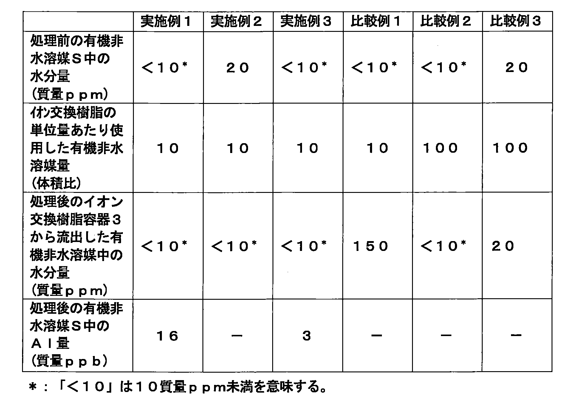
表1より、実施例1~実施例3においては、イオン交換樹脂の前処理装置1において、原液タンク2から、イオン交換樹脂容器3および水分除去装置4の順に有機非水溶媒Sを通液した後、通液した非水溶媒を原液タンク2に返送して循環処理していることから、簡便かつ経済的にイオン交換樹脂容器3内に収容したイオン交換樹脂の含有水分量を高度に低減し得ることが分かる。
また、実施例3においては、水分除去装置の下流側にさらに濾過装置Fを有することから、係る濾過装置Fを有さない実施例1の前処理装置1に比較して、有機非水溶媒中のAl量が低減され、イオン交換樹脂容器中へのゼオライト粒子の混入を抑制し得ることが分かる。
また、実施例3においては、水分除去装置の下流側にさらに濾過装置Fを有することから、係る濾過装置Fを有さない実施例1の前処理装置1に比較して、有機非水溶媒中のAl量が低減され、イオン交換樹脂容器中へのゼオライト粒子の混入を抑制し得ることが分かる。
一方、表1より、比較例1においては、イオン交換樹脂の前処理装置11が水分除去装置4や原液タンク2に処理液を返送する循環送液管Lを有さず、有機非水溶媒を循環して使用するものでないことから、同量の非水溶媒を使用してもイオン交換樹脂の含有水分を十分に低減し得ないことが分かる。
また、表1より、比較例2においては、イオン交換樹脂の前処理装置11が水分除去装置4や原液タンク2に処理液を返送する循環送液管Lを有さず、有機非水溶媒を循環して使用するものでないことから、イオン交換樹脂から流出した有機非水溶媒の水分量を実施例1と同等の水準まで低減するためには、実施例1と比較して10倍量の有機非水溶媒が必要になることが分かる。
さらに、表1より、比較例3においては、イオン交換樹脂の前処理装置11が水分除去装置4や原液タンク2に処理液を返送する循環送液管Lを有さず、有機非水溶媒を循環して使用するものでないことから、処理前の有機非水溶媒中の水分量が20質量ppmと多い場合には、実施例1と比較して10倍量の有機非水溶媒を使用してもイオン交換樹脂の含有水分を十分に低減し得ないことが分かる。
本発明によれば、簡便かつ経済的に含有水分量を低減可能なイオン交換樹脂の前処理装置およびイオン交換樹脂の前処理方法を提供することができる。
1 イオン交換樹脂の前処理装置
2 原液タンク
3 イオン交換樹脂容器
4 水分除去装置
5 貯留タンク
2 原液タンク
3 イオン交換樹脂容器
4 水分除去装置
5 貯留タンク
Claims (8)
- 非水溶媒を貯蔵する原液タンク、イオン交換樹脂を収容したイオン交換樹脂容器および非水溶媒中の水分を除去する水分除去装置を少なくとも有するとともに、
前記原液タンクから、前記イオン交換樹脂容器および前記水分除去装置の順に非水溶媒を通液した後、通液した非水溶媒を前記原液タンクに返送する循環送液管並びに
前記原液タンクから、前記水分除去装置および前記イオン交換樹脂容器の順に非水溶媒を通液した後、通液した非水溶媒を前記原液タンクに返送する循環送液管から選ばれる少なくとも一つの送液管を有する
ことを特徴とするイオン交換樹脂の前処理装置。 - 前記水分除去装置が水分吸着装置である請求項1に記載のイオン交換樹脂の前処理装置。
- 前記水分吸着装置が水分吸着材としてゼオライトを収容したものである請求項2に記載のイオン交換樹脂の前処理装置。
- 前記水分吸着装置に収容されたゼオライトに対し、前記循環送液管内を流通する非水溶媒が上向流で通液するように前記循環送液管が配置されている請求項3に記載のイオン交換樹脂の前処理装置。
- 前記水分除去装置の下流側にさらに濾過装置を有する請求項1~請求項4のいずれかに記載のイオン交換樹脂の前処理装置。
- 前記イオン交換樹脂が陰イオン交換樹脂である請求項1~請求項5のいずれかに記載のイオン交換樹脂の前処理装置。
- 前記イオン交換樹脂が弱塩基性陰イオン交換樹脂である請求項1~請求項6のいずれかに記載のイオン交換樹脂の前処理装置。
- 非水溶媒を貯蔵する原液タンク、イオン交換樹脂を収容したイオン交換樹脂容器および非水溶媒中の水分を除去する水分除去装置を少なくとも有するイオン交換樹脂の前処理装置に対し、
前記原液タンクから、前記イオン交換樹脂容器および前記水分除去装置の順に非水溶媒を通液した後、通液した非水溶媒を前記原液タンクに返送する送液並びに
前記原液タンクから、前記水分除去装置および前記イオン交換樹脂容器の順に非水溶媒を通液した後、通液した非水溶媒を前記原液タンクに返送する送液から選ばれる一種以上の送液を非水溶媒を循環しながら行う
ことを特徴とするイオン交換樹脂の前処理方法。
Priority Applications (4)
| Application Number | Priority Date | Filing Date | Title |
|---|---|---|---|
| US17/426,274 US12151234B2 (en) | 2019-01-30 | 2019-09-27 | Apparatus for pretreating ion exchange resin and method for pretreating ion exchange resin |
| CN201980064270.XA CN112789110A (zh) | 2019-01-30 | 2019-09-27 | 离子交换树脂的预处理装置和离子交换树脂的预处理方法 |
| KR1020217013315A KR102497501B1 (ko) | 2019-01-30 | 2019-09-27 | 이온교환수지의 전처리장치 및 이온교환수지의 전처리방법 |
| EP19913688.8A EP3919170A4 (en) | 2019-01-30 | 2019-09-27 | ION EXCHANGE RESIN PRETREATMENT DEVICE AND ION EXCHANGE RESIN PRETREATMENT METHOD |
Applications Claiming Priority (2)
| Application Number | Priority Date | Filing Date | Title |
|---|---|---|---|
| JP2019-013873 | 2019-01-30 | ||
| JP2019013873A JP7153580B2 (ja) | 2019-01-30 | 2019-01-30 | イオン交換樹脂の前処理装置およびイオン交換樹脂の前処理方法 |
Publications (1)
| Publication Number | Publication Date |
|---|---|
| WO2020158048A1 true WO2020158048A1 (ja) | 2020-08-06 |
Family
ID=71840532
Family Applications (1)
| Application Number | Title | Priority Date | Filing Date |
|---|---|---|---|
| PCT/JP2019/038122 Ceased WO2020158048A1 (ja) | 2019-01-30 | 2019-09-27 | イオン交換樹脂の前処理装置およびイオン交換樹脂の前処理方法 |
Country Status (6)
| Country | Link |
|---|---|
| US (1) | US12151234B2 (ja) |
| EP (1) | EP3919170A4 (ja) |
| JP (1) | JP7153580B2 (ja) |
| KR (1) | KR102497501B1 (ja) |
| CN (1) | CN112789110A (ja) |
| WO (1) | WO2020158048A1 (ja) |
Families Citing this family (6)
| Publication number | Priority date | Publication date | Assignee | Title |
|---|---|---|---|---|
| CN114502279A (zh) * | 2019-11-07 | 2022-05-13 | 奥加诺株式会社 | 非水电解液的制造装置和非水电解液的制造方法 |
| JP7379170B2 (ja) * | 2020-01-07 | 2023-11-14 | オルガノ株式会社 | 非水溶媒の精製方法及び非水溶媒の精製用のイオン交換樹脂の前処理方法 |
| KR20230163544A (ko) | 2021-03-31 | 2023-11-30 | 오르가노 코포레이션 | 비수액의 정제방법 및 정제장치, 그리고 이온교환수지의 제조방법 및 전처리장치 |
| JP7840222B2 (ja) * | 2022-07-11 | 2026-04-03 | オルガノ株式会社 | 液体精製装置の運転方法 |
| CN115286013B (zh) * | 2022-09-19 | 2023-03-31 | 安徽新宸新材料有限公司 | 一种六氟磷酸盐的制备方法 |
| JP2026020704A (ja) * | 2024-07-29 | 2026-02-10 | オルガノ株式会社 | イオン交換樹脂の前処理装置および前処理方法 |
Citations (4)
| Publication number | Priority date | Publication date | Assignee | Title |
|---|---|---|---|---|
| JPS5660648A (en) * | 1979-10-22 | 1981-05-25 | Mitsubishi Chem Ind Ltd | Dehydration of nonaqueous liquid using ion exchange resin |
| JPS61151241A (ja) * | 1984-12-25 | 1986-07-09 | Asahi Glass Co Ltd | イオン交換膜の前処理方法 |
| JPH06238271A (ja) * | 1992-10-07 | 1994-08-30 | Christ Ag | イオン交換樹脂のコンディショニング法 |
| JPH078810A (ja) * | 1993-06-28 | 1995-01-13 | Hisashi Nakai | イオン交換樹脂の特定元素除去方法 |
Family Cites Families (12)
| Publication number | Priority date | Publication date | Assignee | Title |
|---|---|---|---|---|
| US6001325A (en) | 1996-11-26 | 1999-12-14 | Fmc Corporation | Process for removing acids from lithium salt solutions |
| JPH11276801A (ja) * | 1998-03-27 | 1999-10-12 | Mitsubishi Chemical Engineering Corp | 混合液体精製方法及び混合液体精製装置 |
| WO2012115081A1 (ja) * | 2011-02-21 | 2012-08-30 | 東洋紡績株式会社 | 有機溶剤脱水装置 |
| JP5762861B2 (ja) | 2011-07-15 | 2015-08-12 | オルガノ株式会社 | アルコールの精製方法及び装置 |
| JP5762860B2 (ja) | 2011-07-15 | 2015-08-12 | オルガノ株式会社 | アルコールの精製方法及び装置 |
| JP5762863B2 (ja) * | 2011-07-15 | 2015-08-12 | オルガノ株式会社 | アルコールの精製方法及び装置 |
| CN109081773A (zh) | 2012-03-27 | 2018-12-25 | 株式会社可乐丽 | 3-烷氧基-3-甲基-1-丁醇的制造方法 |
| JP5930921B2 (ja) | 2012-09-13 | 2016-06-08 | オルガノ株式会社 | アルコールの精製方法及び装置 |
| JP5907326B1 (ja) * | 2014-08-12 | 2016-04-26 | 株式会社アイスティサイエンス | アミノ酸、有機酸及び糖質の分析前処理装置及び分析前処理方法 |
| CN105037156A (zh) * | 2015-07-13 | 2015-11-11 | 苏州晶瑞化学股份有限公司 | 一种超净高纯乙酸乙酯的生产方法 |
| ES2983636T3 (es) | 2015-12-28 | 2024-10-24 | Dow Global Technologies Llc | Proceso de purificación para disolvente orgánico hidrolizable |
| WO2018043697A1 (ja) * | 2016-09-02 | 2018-03-08 | 富士フイルム株式会社 | 有機溶剤の精製方法および有機溶剤の精製装置 |
-
2019
- 2019-01-30 JP JP2019013873A patent/JP7153580B2/ja active Active
- 2019-09-27 WO PCT/JP2019/038122 patent/WO2020158048A1/ja not_active Ceased
- 2019-09-27 US US17/426,274 patent/US12151234B2/en active Active
- 2019-09-27 CN CN201980064270.XA patent/CN112789110A/zh active Pending
- 2019-09-27 EP EP19913688.8A patent/EP3919170A4/en active Pending
- 2019-09-27 KR KR1020217013315A patent/KR102497501B1/ko active Active
Patent Citations (4)
| Publication number | Priority date | Publication date | Assignee | Title |
|---|---|---|---|---|
| JPS5660648A (en) * | 1979-10-22 | 1981-05-25 | Mitsubishi Chem Ind Ltd | Dehydration of nonaqueous liquid using ion exchange resin |
| JPS61151241A (ja) * | 1984-12-25 | 1986-07-09 | Asahi Glass Co Ltd | イオン交換膜の前処理方法 |
| JPH06238271A (ja) * | 1992-10-07 | 1994-08-30 | Christ Ag | イオン交換樹脂のコンディショニング法 |
| JPH078810A (ja) * | 1993-06-28 | 1995-01-13 | Hisashi Nakai | イオン交換樹脂の特定元素除去方法 |
Non-Patent Citations (1)
| Title |
|---|
| See also references of EP3919170A4 * |
Also Published As
| Publication number | Publication date |
|---|---|
| KR20210062080A (ko) | 2021-05-28 |
| US20220105505A1 (en) | 2022-04-07 |
| US12151234B2 (en) | 2024-11-26 |
| JP2020121261A (ja) | 2020-08-13 |
| JP7153580B2 (ja) | 2022-10-14 |
| CN112789110A (zh) | 2021-05-11 |
| KR102497501B1 (ko) | 2023-02-08 |
| EP3919170A1 (en) | 2021-12-08 |
| EP3919170A4 (en) | 2022-10-19 |
Similar Documents
| Publication | Publication Date | Title |
|---|---|---|
| JP7153580B2 (ja) | イオン交換樹脂の前処理装置およびイオン交換樹脂の前処理方法 | |
| KR102627185B1 (ko) | 비수전해액의 제조장치 및 비수전해액의 제조방법 | |
| US8864999B2 (en) | Methods for regenerating acidic ion-exchange resins and reusing regenerants in such methods | |
| JP2020195947A (ja) | イオン交換樹脂の前処理装置およびイオン交換樹脂の前処理方法 | |
| JP2020195946A (ja) | イオン交換樹脂の前処理装置およびイオン交換樹脂の前処理方法 | |
| US10610860B2 (en) | Method of purifying water | |
| KR20120094548A (ko) | 음이온 교환성 고분자로 코팅된 탄소전극 제조 방법 | |
| US20070238907A1 (en) | Method for removing sulfur compounds from an alcohol stream | |
| JP7602418B2 (ja) | 非水溶媒の精製方法および精製装置 | |
| JP2023137717A (ja) | 過酸化水素水精製用混合床イオン交換体の調製方法および過酸化水素水の精製方法 | |
| JP7585220B2 (ja) | 非水電解液の製造方法 | |
| JP7498530B1 (ja) | 有機溶媒の精製方法及び精製有機溶媒の製造方法、並びに有機溶媒の精製システム | |
| US10301197B2 (en) | Method of purifying water | |
| US10610859B2 (en) | Method of purifying water | |
| JP7259919B1 (ja) | 有機溶媒の不純物除去方法 | |
| WO2022209391A1 (ja) | 非水液の精製方法および精製装置、ならびにイオン交換樹脂の製造方法および前処理装置 | |
| WO2026028557A1 (ja) | イオン交換樹脂の前処理装置および前処理方法 |
Legal Events
| Date | Code | Title | Description |
|---|---|---|---|
| 121 | Ep: the epo has been informed by wipo that ep was designated in this application |
Ref document number: 19913688 Country of ref document: EP Kind code of ref document: A1 |
|
| ENP | Entry into the national phase |
Ref document number: 20217013315 Country of ref document: KR Kind code of ref document: A |
|
| NENP | Non-entry into the national phase |
Ref country code: DE |
|
| ENP | Entry into the national phase |
Ref document number: 2019913688 Country of ref document: EP Effective date: 20210830 |