WO2020158909A1 - 計数装置、学習器製造装置、計数方法、及び学習器製造方法 - Google Patents
計数装置、学習器製造装置、計数方法、及び学習器製造方法 Download PDFInfo
- Publication number
- WO2020158909A1 WO2020158909A1 PCT/JP2020/003594 JP2020003594W WO2020158909A1 WO 2020158909 A1 WO2020158909 A1 WO 2020158909A1 JP 2020003594 W JP2020003594 W JP 2020003594W WO 2020158909 A1 WO2020158909 A1 WO 2020158909A1
- Authority
- WO
- WIPO (PCT)
- Prior art keywords
- counting
- image
- training
- objects
- learning device
- Prior art date
- Legal status (The legal status is an assumption and is not a legal conclusion. Google has not performed a legal analysis and makes no representation as to the accuracy of the status listed.)
- Ceased
Links
Images















Classifications
-
- G—PHYSICS
- G06—COMPUTING OR CALCULATING; COUNTING
- G06N—COMPUTING ARRANGEMENTS BASED ON SPECIFIC COMPUTATIONAL MODELS
- G06N3/00—Computing arrangements based on biological models
- G06N3/02—Neural networks
- G06N3/08—Learning methods
- G06N3/084—Backpropagation, e.g. using gradient descent
-
- G—PHYSICS
- G06—COMPUTING OR CALCULATING; COUNTING
- G06F—ELECTRIC DIGITAL DATA PROCESSING
- G06F18/00—Pattern recognition
- G06F18/20—Analysing
- G06F18/21—Design or setup of recognition systems or techniques; Extraction of features in feature space; Blind source separation
- G06F18/214—Generating training patterns; Bootstrap methods, e.g. bagging or boosting
-
- G—PHYSICS
- G06—COMPUTING OR CALCULATING; COUNTING
- G06F—ELECTRIC DIGITAL DATA PROCESSING
- G06F18/00—Pattern recognition
- G06F18/20—Analysing
- G06F18/21—Design or setup of recognition systems or techniques; Extraction of features in feature space; Blind source separation
- G06F18/217—Validation; Performance evaluation; Active pattern learning techniques
-
- G—PHYSICS
- G06—COMPUTING OR CALCULATING; COUNTING
- G06M—COUNTING MECHANISMS; COUNTING OF OBJECTS NOT OTHERWISE PROVIDED FOR
- G06M11/00—Counting of objects distributed at random, e.g. on a surface
-
- G—PHYSICS
- G06—COMPUTING OR CALCULATING; COUNTING
- G06N—COMPUTING ARRANGEMENTS BASED ON SPECIFIC COMPUTATIONAL MODELS
- G06N20/00—Machine learning
-
- G—PHYSICS
- G06—COMPUTING OR CALCULATING; COUNTING
- G06N—COMPUTING ARRANGEMENTS BASED ON SPECIFIC COMPUTATIONAL MODELS
- G06N3/00—Computing arrangements based on biological models
- G06N3/02—Neural networks
- G06N3/04—Architecture, e.g. interconnection topology
- G06N3/045—Combinations of networks
-
- G—PHYSICS
- G06—COMPUTING OR CALCULATING; COUNTING
- G06N—COMPUTING ARRANGEMENTS BASED ON SPECIFIC COMPUTATIONAL MODELS
- G06N3/00—Computing arrangements based on biological models
- G06N3/02—Neural networks
- G06N3/04—Architecture, e.g. interconnection topology
- G06N3/0464—Convolutional networks [CNN, ConvNet]
-
- G—PHYSICS
- G06—COMPUTING OR CALCULATING; COUNTING
- G06N—COMPUTING ARRANGEMENTS BASED ON SPECIFIC COMPUTATIONAL MODELS
- G06N3/00—Computing arrangements based on biological models
- G06N3/02—Neural networks
- G06N3/08—Learning methods
- G06N3/09—Supervised learning
-
- G—PHYSICS
- G06—COMPUTING OR CALCULATING; COUNTING
- G06V—IMAGE OR VIDEO RECOGNITION OR UNDERSTANDING
- G06V10/00—Arrangements for image or video recognition or understanding
- G06V10/20—Image preprocessing
- G06V10/255—Detecting or recognising potential candidate objects based on visual cues, e.g. shapes
-
- G—PHYSICS
- G06—COMPUTING OR CALCULATING; COUNTING
- G06V—IMAGE OR VIDEO RECOGNITION OR UNDERSTANDING
- G06V10/00—Arrangements for image or video recognition or understanding
- G06V10/20—Image preprocessing
- G06V10/26—Segmentation of patterns in the image field; Cutting or merging of image elements to establish the pattern region, e.g. clustering-based techniques; Detection of occlusion
-
- G—PHYSICS
- G06—COMPUTING OR CALCULATING; COUNTING
- G06V—IMAGE OR VIDEO RECOGNITION OR UNDERSTANDING
- G06V10/00—Arrangements for image or video recognition or understanding
- G06V10/40—Extraction of image or video features
- G06V10/44—Local feature extraction by analysis of parts of the pattern, e.g. by detecting edges, contours, loops, corners, strokes or intersections; Connectivity analysis, e.g. of connected components
- G06V10/443—Local feature extraction by analysis of parts of the pattern, e.g. by detecting edges, contours, loops, corners, strokes or intersections; Connectivity analysis, e.g. of connected components by matching or filtering
- G06V10/449—Biologically inspired filters, e.g. difference of Gaussians [DoG] or Gabor filters
- G06V10/451—Biologically inspired filters, e.g. difference of Gaussians [DoG] or Gabor filters with interaction between the filter responses, e.g. cortical complex cells
- G06V10/454—Integrating the filters into a hierarchical structure, e.g. convolutional neural networks [CNN]
-
- G—PHYSICS
- G06—COMPUTING OR CALCULATING; COUNTING
- G06V—IMAGE OR VIDEO RECOGNITION OR UNDERSTANDING
- G06V10/00—Arrangements for image or video recognition or understanding
- G06V10/40—Extraction of image or video features
- G06V10/56—Extraction of image or video features relating to colour
-
- G—PHYSICS
- G06—COMPUTING OR CALCULATING; COUNTING
- G06V—IMAGE OR VIDEO RECOGNITION OR UNDERSTANDING
- G06V10/00—Arrangements for image or video recognition or understanding
- G06V10/70—Arrangements for image or video recognition or understanding using pattern recognition or machine learning
- G06V10/82—Arrangements for image or video recognition or understanding using pattern recognition or machine learning using neural networks
-
- G—PHYSICS
- G06—COMPUTING OR CALCULATING; COUNTING
- G06V—IMAGE OR VIDEO RECOGNITION OR UNDERSTANDING
- G06V20/00—Scenes; Scene-specific elements
- G06V20/60—Type of objects
- G06V20/66—Trinkets, e.g. shirt buttons or jewellery items
-
- G—PHYSICS
- G06—COMPUTING OR CALCULATING; COUNTING
- G06N—COMPUTING ARRANGEMENTS BASED ON SPECIFIC COMPUTATIONAL MODELS
- G06N3/00—Computing arrangements based on biological models
- G06N3/02—Neural networks
- G06N3/04—Architecture, e.g. interconnection topology
- G06N3/048—Activation functions
-
- G—PHYSICS
- G06—COMPUTING OR CALCULATING; COUNTING
- G06V—IMAGE OR VIDEO RECOGNITION OR UNDERSTANDING
- G06V2201/00—Indexing scheme relating to image or video recognition or understanding
- G06V2201/06—Recognition of objects for industrial automation
Definitions
- the present invention relates to a counting device or the like that counts the number of counting targets.
- Patent Document 1 there is a method of counting objects by performing matching processing using a shape model automatically generated using an imaging guide in a captured image of an aggregate of counting objects (for example, Patent Document 1). reference).
- the present invention has been made to solve the above problems, and an object of the present invention is to provide a counting device and the like that can improve counting accuracy.
- the counting device includes a training input image, which is an image in which a plurality of counting objects having the same shape are photographed, and teacher figures arranged at respective positions of the plurality of counting objects.
- a storage unit that stores a learning device that has been learned by using a plurality of sets of output images for training including, a captured image acquisition unit that acquires captured images of a plurality of counting objects, and the captured image is applied to the learning device.
- the output image acquisition unit that acquires the output image in which each counting object included in the captured image is converted into the counting object figure, and the number of counting objects using the plurality of counting object figures included in the output image
- a output unit for outputting the number of counting objects counted by the counting unit.
- the counting device further comprises, for each counting target figure included in the output image, a certainty factor acquiring section that acquires a certainty factor having a higher value as the attribute of the counting target figure is closer to the attribute of the teacher figure,
- the counting section may count the number of figures to be counted whose confidence factor exceeds a threshold value.
- the counting device there are a plurality of types regarding the size of the counting object, and the learning device is learned using the teacher figure having different attributes for each size of the counting object.
- the counting unit may count the number of counting objects of a size that has not been learned by using the attribute and the certainty factor of the counting object graphic included in the output image.
- the learning device manufacturing apparatus includes a training input image, which is an image in which a plurality of counting objects having the same shape are photographed, and a training including a teacher figure arranged at each position of the plurality of counting objects.
- a training image reception unit that receives a plurality of sets of training output images, a learning device manufacturing unit that manufactures a learning device by learning a plurality of sets of training input images and training output images, and outputs a learning device And a learning device output unit.
- the training image receiving unit may receive a training output image including a teacher figure having different attributes for each type of counting object.
- the training image receiving unit may receive a set of a training input image and a training output image for each type of counting object.
- the learning device is generated with a smaller number of pairs of training input images and training output images than when learning is performed using one training input image including a plurality of types of counting objects. You will be able to.
- the type of counting object may be a type relating to the size of the counting object.
- the teacher figure may be a figure without directionality.
- the teacher figure may be a directional figure in which the direction is set according to the direction of the counting object in the training input image.
- the learning device includes a training input image, which is an image in which a plurality of counting objects having the same shape are photographed, and a training output including a teacher figure arranged at each position of the plurality of counting objects.
- a learning device of a plurality of sets of learning results with an image, and when a captured image of a plurality of counting objects is applied, an output image in which each counting object included in the captured image is converted into a counting target figure is output. That's what you can get.
- the counting method includes a captured image acquisition step of acquiring captured images of a plurality of counting objects, and a captured image as a training input image that is an image of a plurality of counting objects of the same shape.
- a captured image acquisition step of acquiring captured images of a plurality of counting objects, and a captured image as a training input image that is an image of a plurality of counting objects of the same shape.
- the learning device manufacturing method includes a training input image which is an image in which a plurality of counting objects having the same shape are photographed, and a training including a teacher figure arranged at each position of the plurality of counting objects.
- Block diagram showing the configuration of a counting device according to an embodiment of the present invention Block diagram showing the configuration of the learning device manufacturing apparatus according to the embodiment Flowchart showing the operation of the counting apparatus according to the embodiment Flowchart showing the operation of the learning device manufacturing apparatus according to the embodiment
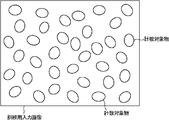
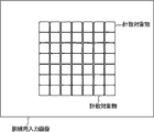
- the figure which shows an example of the training input image in the same embodiment The figure which shows an example of the training output image in the same embodiment.
- the figure which shows an example of the synthetic image for reference in the same embodiment. The figure which shows an example of the training input image in the same embodiment.
- the figure which shows an example of the synthetic image for reference in the same embodiment The figure which shows an example of the picked-up image in the same embodiment.
- the figure which shows an example of the output image in the same embodiment The figure which shows an example of the synthetic image for reference in the same embodiment.
- the figure which shows an example of the picked-up image in the same embodiment The figure which shows an example of the output image in the same embodiment.
- the figure which shows an example of the synthetic image for reference in the same embodiment. The figure which shows an example of the picked-up image in the same embodiment.
- the figure which shows an example of the output image in the same embodiment The figure which shows an example of the synthetic image for reference in the same embodiment.
- FIG 3 is a diagram for explaining an expansion layer in the neural network according to the same embodiment.
- the counting device uses the learning device learned using the training input image and the training output image to convert the counting target included in the captured image into a figure, thereby counting the counting target. To count the number of. Further, the learning device manufacturing apparatus according to the present embodiment manufactures a learning device used for counting objects to be counted by performing learning using a plurality of sets of a training input image and a training output image. Can be done.
- FIG. 1 is a block diagram showing the configuration of the counting device 1 according to this embodiment.
- the counting device 1 according to the present embodiment includes a storage unit 11, a captured image acquisition unit 12, an output image acquisition unit 13, a certainty factor acquisition unit 14, a counting unit 15, and an output unit 16.
- the counting device 1 may be, for example, a personal computer, a portable information processing terminal such as a smartphone, a tablet terminal, a PDA (Personal Digital Assistant), or the like, and is a dedicated device for performing counting processing. It may be a server or the like.
- the learning unit is stored in the storage unit 11.
- This learning device is a training input image that is an image of a plurality of counting objects of the same shape, and a training output image including a teacher figure arranged at each position of the counting objects. It was learned by using multiple sets.
- a set of the training input image and the training output image may be referred to as a training image.
- the learning device may be, for example, a learning result of a neural network (NN: Neural Network) or a learning result of a support vector machine (SVM: Support Vector Machine) or a support vector regression (SVR: Support Vector Regression). Alternatively, it may be the learning result of other machine learning.
- the neural network may be, for example, a convolutional neural network (CNN: Convolutional Neural Network), or may be another neural network (for example, a neural network including fully connected layers).
- a convolutional neural network is a neural network having one or more convolutional layers.
- the learning of the neural network may be considered to be deep learning.
- the number of layers of the neural network, the number of nodes in each layer, the type of each layer (eg, convolutional layer, fully connected layer, etc.) can be selected appropriately. Good. Note that the number of nodes in the input layer and the output layer is usually determined by the training input image and the training output image included in the training image. In the present embodiment, the case where the learning device is the learning result of CNN will be mainly described, and the other cases will be described later.
- the learning device even if the learning device is stored in the storage unit 11, for example, the learning device itself (for example, a function that outputs a value with respect to an input or a model of a learning result) is stored. It may well be that information such as parameters necessary for configuring the learning device is stored. Even in the latter case, the learning device can be configured by using the information such as the parameters, so that it can be considered that the learning device is substantially stored in the storage unit 11. In the present embodiment, the case where the learning device itself is stored in the storage unit 11 will be mainly described.
- the process of storing the learning device in the storage unit 11 does not matter.
- the learning device may be stored in the storage unit 11 via a recording medium, or the learning device transmitted via a communication line or the like may be stored in the storage unit 11.
- the storage in the storage unit 11 may be temporary storage such as RAM or long-term storage.
- the storage unit 11 can be realized by a predetermined recording medium (for example, a semiconductor memory, a magnetic disk, an optical disk, etc.).
- FIG. 2 is a block diagram showing the configuration of the learning device manufacturing apparatus 2 according to this embodiment.
- the learning device manufacturing apparatus 2 according to the present embodiment includes a training image receiving unit 21, a learning device manufacturing unit 22, and a learning device output unit 23.
- the learning device manufacturing apparatus 2 is usually an information processing apparatus that performs learning, but may be a general-purpose apparatus such as a portable information processing terminal or a dedicated apparatus that performs learning, for example. It may be a server or the like.
- the training image reception unit 21 includes a training input image, which is an image in which a plurality of counting objects having the same shape are photographed, and a training output image including a teacher figure arranged at each position of the plurality of counting objects. Accept multiple pairs of and.
- the plurality of counting objects have the same shape as described above.
- the same shape may be exactly the same shape or may be substantially the same shape.
- the plurality of counting objects may have the same size.
- the same size may be exactly the same size or may be substantially the same size.
- the counting object is a natural product such as a crop
- soybean, rice, plant seeds, etc. may be considered to have the same shape and size.
- the counting object is an artificial object such as a screw or a bolt
- the degree is smaller than the natural object, but strictly speaking, there is a slight difference in the shape and size of each counting object. It is possible to do it. Even in such a case, if they can be determined to have substantially the same shape and the same size, they may be considered to have the same shape and the same size. It should be noted that whether or not they have the same size is usually judged by the size according to the number of pixels. Further, it is preferable that the plurality of counting objects included in the training input image include variations in the shape and size of the counting object to be counted.
- the object to be counted when the object to be counted is a natural object, there may be a minute difference in shape or size, but various objects to be counted including such minute difference may be included. It is preferably included in the training input image. By doing so, a count that is not affected by such a difference can be realized.
- a case where a plurality of counting objects have the same shape and the same size will be mainly described.
- the teacher figure is a figure smaller than the counting object. By doing so, even when a part of the counting object overlaps, if the counting object does not entirely overlap, the counting object is converted into a counting object graphic as described later. Because it can be done. Further, it is preferable that the teacher figure is arranged at a position corresponding to the center of the counting object, but it is not always necessary. However, even when the teacher figure is arranged at a position other than the position corresponding to the center of the counting object, it is preferable that the teacher figure is arranged at a position corresponding to the predetermined position of the counting object. is there.
- the shape of the teacher figure does not matter, but for example, the teacher figure may be a figure without directionality.
- the non-directional figure is a figure that does not deform even when rotated on the image, and may be, for example, a ring shape or a disk shape.
- the teacher figure may be, for example, a figure having directionality.
- the teacher graphic having directionality may have, for example, a triangular shape, a quadrangular shape, a polygonal shape, a linear shape, or the like.
- a directional linear teacher pattern may be used.
- the teacher figure may be arranged such that the longitudinal direction of the linear counting object is the longitudinal direction of the taught figure. If the objects to be counted have a directional shape and are arranged in a certain direction, for example, a directional teacher figure may be used. In that case, for example, it is preferable that the orientation (angle) of the teacher figure is determined according to the shape of the counting object.
- the teaching pattern is arranged at a position corresponding to the center of the counting object so that the direction of each side of the square teaching pattern is aligned with each side of the counting object. May be done.
- Angled teacher figures may be arranged respectively.
- the training image receiving unit 21 may receive a training output image including a teacher figure having different attributes for each type of counting object.
- the type of counting object may be, for example, a type related to shape, a type related to size, a type related to color, or another type, or those types. It may be an arbitrary combination of two or more. Examples of counting objects having different shapes and sizes include soybean and rice. Further, the counting objects having different sizes include, for example, nuts having different sizes. Further, examples of counting objects having different colors include normal soybean and green soybean.
- the attribute of the teacher figure may be, for example, a color (for example, at least one of hue, saturation, and lightness), a shape, or another attribute. For example, when soybeans and rice are used as the objects to be counted, a red teacher pattern may be used for soybeans and a blue teacher pattern may be used for rice.
- the training image receiving unit 21 may receive a set of a training input image and a training output image for each type of counting object. That is, one set of training images includes a training input image including only one type of counting object and a training output image including only a teacher figure having an attribute corresponding to the counting object. May be.
- the training image reception unit 21 sets the training image input image and training output image for soybeans to a plurality of sets, and the training input image and training output image for rice. Multiple sets of information may be accepted.
- the teacher figure has attributes such as a predetermined shape and color.
- the shape and size of the teacher figure may be fixed.
- the color attribute (for example, lightness, hue, saturation) of the teacher figure may be determined in advance. In that case, for example, all the color attributes of each pixel forming the teacher figure may be the same.
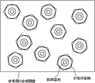
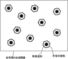
- FIG. 5A is a training input image of a counting object that is soybean
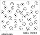
- FIG. 5B is a non-directional teacher figure (that is, a disk) arranged at each position of soybeans in the training input image of FIG. 5A. It is an output image for training including a shape teacher figure).
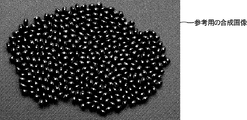
- FIG. 5C is a reference diagram in which the training input image of FIG. 5A and the training output image of FIG. 5B are combined. As shown in FIG. 5C, each teacher figure is arranged at the center position of the counting object.
- FIG. 6A is a training input image in which the ends of counting objects, which are a plurality of stacked dry noodles having a square cross section, are photographed
- FIG. 6B is a training input image of the training input image of FIG. 6A. It is an output image for training that includes teacher graphics having directionality, which are arranged at respective positions.
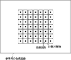
- each teacher figure is an object to be counted at the end of a bar-shaped dry noodle that is an object to be counted. Are arranged so that each side is aligned with the square shape.
- FIG. 6C is a reference diagram in which the training input image of FIG. 6A and the training output image of FIG. 6B are combined. As shown in FIG. 6C, each teacher figure is arranged at the center position of the counting object so that its orientation is aligned with that of the counting object.
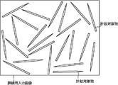
- FIG. 7A is a training input image of a counting object that is a toothpick
- FIG. 7B is a directional teacher figure (that is, a linear shape) arranged at each of the toothpick positions in the training input image of FIG. 7A. Is an output image for training including a teacher figure).
- FIG. 7C is a reference diagram in which the training input image of FIG. 7A and the training output image of FIG. 7B are combined. As shown in FIG. 7C, each teacher figure is arranged at the center position of the counting object so as to be in the same direction as the counting object.
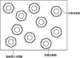
- FIG. 8A and 8B are input images for training of a counting object that is a nut.
- the nut of the training input image of FIG. 8A has a larger size than the nut of the training input image of FIG. 8B.
- the nut of FIG. 8A is referred to as a “large nut” and the nut of FIG. 8B is referred to as a “small nut”.
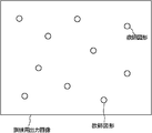
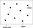
- FIG. 8C is an output image for training including teacher graphics having no directionality, which are respectively arranged at the positions of large nuts of the input image for training in FIG. 8A
- FIG. 8D is a small image of the input image for training in FIG. 8B.
- the teacher figure included in the training output image of FIG. 8C is a white figure
- the teacher figure included in the training output image of FIG. 8D is a black figure.
- teacher figures having different attributes that is, different lightness
- FIG. 8E is a reference diagram in which the training input image of FIG. 8A and the training output image of FIG. 8C are combined
- FIG. 8F is the training input image of FIG. 8B and the training output image of FIG. 8D. It is the reference figure which synthesize
- the teacher graphic is arranged at the position of the hole of the nut which is the counting object.
- arranging the teacher figure at the position of the counting object may mean that the teacher figure is arranged at a position overlapping with the counting object as shown in FIG. 5C and the like.
- the teacher figure may be arranged at a position that does not overlap the counting object.
- FIG. 5 to 8 show a set of training input images and training output images, respectively, a plurality of sets of training input images and training output images are normally used for learning. ..
- the counting object is soybean
- the training image or the like shown in FIG. 5 is used
- the counting object is dry noodles
- the training image or the like shown in FIG. 6 is used and the counting object is
- the object is a toothpick
- the training image or the like shown in FIG. 7 may be used
- the training image or the like shown in FIG. 8 may be used.
- the number of sets of training input images and training output images used for learning is large, but in order to prepare a larger number of training input images and training output images, more cost is required. Will be costly. Therefore, it is preferable to perform the learning by using a set of the training input image and the training output image that can perform appropriate counting. For example, in the case of the soybean shown in FIG. 5, about 300 to 500 grains of soybean may be used to prepare about 50 sets of training input images and training output images for learning.
- the training image reception unit 21 may receive information transmitted via a wired or wireless communication line, for example, and is read from a predetermined recording medium (eg, optical disk, magnetic disk, semiconductor memory, etc.). Information may be accepted.
- the training image reception unit 21 may or may not include a device (for example, a modem or a network card) for receiving the training image. Further, the training image accepting unit 21 may be realized by hardware, or may be realized by software such as a driver that drives a predetermined device.
- the learning device manufacturing unit 22 manufactures a learning device by learning a plurality of sets of a training input image and a training output image.
- This learning device is a training input image that is an image of a counting object, and a training output image that includes a plurality of teacher figures arranged at respective positions of the counting object included in the training input image.
- the figure to be counted is a figure corresponding to the teacher figure, and ideally has the same attributes (for example, shape, size, color, etc.) as the teacher figure.
- the training input image and the training output image may be divided and used during learning. For example, as an input, a divided image of a predetermined portion obtained by dividing a training input image is used, and as an output corresponding to the input, a divided output image for training is provided at a portion corresponding to a predetermined portion of the input. Divided images may be used. Note that when the images are divided, the divided images may or may not overlap (overlap). Details of this learning will be described later.
- the learning device output unit 23 outputs the learning device manufactured by the learning device manufacturing unit 22.
- the learning device output by the learning device output unit 23 is stored in the storage unit 11 of the counting device 1 illustrated in FIG. 1.
- this output may be, for example, transmission to a predetermined device via a communication line, storage in a recording medium, or delivery to another component.
- the learning device output unit 23 may or may not include a device (for example, a communication device) that outputs.
- the learner output unit 23 may be realized by hardware or may be realized by software such as a driver that drives those devices.
- This machine learning may be learning with a teacher, learning of a neural network, learning of support vector machines or support vector regression, or other machine learning.
- the case where the machine learning is learning of a neural network will be mainly described.
- the neural network that is a learning device is a neural network that performs image processing, and performs a predetermined calculation on each pixel value of the input image and outputs each pixel value of the output image.
- the neural network may have a plurality of convolutional layers (conv1 to conv4) in the subsequent stage of the input layer, for example, as shown in FIG. 14A.
- FIG. 14A shows the configuration of each layer from the input layer to the output layer (enlargement layer 4).
- this neural network may or may not have one or more pooling layers.
- the number of continuous convolutional layers included in the neural network does not matter.
- the neural network may have three or more consecutive convolutional layers, or may have five or more consecutive convolutional layers.
- padding may be appropriately performed in each layer of the neural network.
- the padding may be, for example, zero padding, extrapolation of the pixel values at the outermost periphery of the image, or padding with pixel values folded at each side of the image.
- FIG. 14A shows an example in which padding is performed, padding does not have to be performed.
- the stride in each layer is not limited, but for example, the stride in the convolutional layer is preferably a small value such as 1 or 2, and when the neural network has a pooling layer, the stride in the pooling layer is It is preferably 2 or more.
- a 4-channel input image is converted into a 1-channel output image.
- the four pixels 1 to 4 in the first row from the top of the channels 0 to 3 and the first column from the left constitute the 2 ⁇ 2 pixels 1 to 4 at the upper left end of the enlarged output image. Will be.
- the four pixels 5 to 8 in the first row from the top of channels 0 to 3 and the second column from the left allow the first to second rows from the top of the enlarged output image and the third to fourth columns from the left.
- Four pixels 5 to 8 will be formed. The same applies to other pixels.
- Pixel (x, y) of the output image (output map) of the expansion layer is the pixel (floor(mod(x, r)+r ⁇ mod(y, r))) channel of the input image (input map).
- x/r), floor(y/r) indicates the horizontal position of the output image
- y indicates the vertical position of the output image
- mod(a,b) is the remainder of a of b
- floor is the floor function.
- the input image is assumed to include r 2 pieces of channel from channel 0 to channel r 2 -1.
- r is usually an integer of 2 or more.
- the pixel at the upper left corner is (0, 0)
- the pixel is i pixel to the right and j pixel downward to (i, j).
- this enlargement layer obtains an output image of one channel, which is multiplied by r in the vertical and horizontal directions, using the input images of the r 2 channels, and the r ⁇ r block in the output image is , R 2 channels of the input image, r 2 pixels at positions corresponding to the block.
- the convolutional layer may or may not exist after the expansion layer. Further, in the neural network, it is preferable that the image of the output layer has the same size as the image of the input layer by one or more enlargement layers. Note that FIG. 14A shows the case where the image of the input layer is a 3-channel color image and the image of the output layer is a 1-channel grayscale image, but this is not necessary.
- the image of the input layer may be a 1-channel grayscale image, and the image of the output layer may be a 3-channel color image.
- the expansion layer may be other than the above.
- an unpooling layer or a deconvolution layer may be used as the layer of the neural network that outputs an image larger than the input image.
- FIG. 14A shows the case where the former stage has a plurality of convolutional layers and the latter stage has one or more expansion layers, but the neural network may have other configurations. ..
- a bias may or may not be used in each layer. Whether to use the bias may be determined independently for each layer.
- the bias may be, for example, a layer-by-layer bias or a filter-by-filter bias. In the former case, one bias is used in each layer, and in the latter case, one or more (the same number as the filters) bias is used in each layer.
- the bias is used in the convolutional layer, the result obtained by multiplying each pixel value by the filter parameter and adding the result to the bias is input to the activation function.
- the learning result of the neural network that is the learning device in the present embodiment
- the learning result of the neural network used in segmentation may be used. That is, the structure of the neural network may be a segmentation type, and the training image may be the one described in the present embodiment for learning.
- the activation function may be, for example, ReLU (normalized linear function), a sigmoid function, or another activation function.
- the loss function (error function) may be a mean square error.
- the number of epochs (the number of times the parameters are updated) is not particularly limited, but it is preferable to select the number of epochs that does not cause overfitting.
- a known method can be used as a learning method in machine learning, and a detailed description thereof will be omitted.
- the captured image acquisition unit 12 acquires captured images of a plurality of counting objects having the same shape.
- This captured image is usually an image of a collection of counting objects.
- the sizes of the plurality of counting objects included in the training input image are the same, the sizes of the plurality of counting objects in the captured image are the same as those of the counting objects included in the training input image. It is preferable that the size is the same as that of the object. Further, when the sizes of the plurality of counting objects included in the training input image are not the same, the sizes of the plurality of counting objects in the captured image are the same as those of the counting objects included in the training input image. It is preferable that the size is within the range.
- the optical system settings for example, focal length, etc.
- the captured image is captured such that the distance to the counting target is the same as when capturing the training input image.
- the training input image is a color image
- the captured image is also a color image
- the training input image is a grayscale image
- the captured image is also a grayscale image.
- the captured image is usually a still image, but the frame included in the moving image may be considered to be the captured image. Strictly speaking, what is included in the captured image and the training input image is the image of the counting object, but for simplicity, it is described that the captured image and the training input image include the counting object. I will decide.
- the captured image acquisition unit 12 may acquire the captured image with an optical device such as a camera, or may accept the captured image acquired with an optical device such as a camera.
- the reception may be reception of a captured image transmitted via a communication line, and a predetermined recording medium (for example, an optical disc, a magnetic disc, a semiconductor memory). It is also possible to read the photographed image from (for example).
- the captured image acquisition unit 12 may store the acquired captured images in a recording medium (not shown).
- the output image acquisition unit 13 applies the captured image acquired by the captured image acquisition unit 12 to the learning device stored in the storage unit 11 so that each counting object included in the captured image is a counting target graphic. Obtain the output image converted to. Specifically, the output image acquisition unit 13 can acquire the output image that is the output of the learning device by inputting each pixel value of the captured image acquired by the captured image acquisition unit 12 into the learning device. it can. When the storage unit 11 stores a function or model that is a learning device, the output image acquisition unit 13 acquires the output image by performing a calculation using the function or model of the captured image. May be.
- the figure to be counted is a figure corresponding to the object to be counted, and ideally has the same shape and color as the teacher figure, but may actually have a shape and color that deviate from the teacher figure.
- the learning device to which the captured image is applied is a teacher figure having different attributes for each type of counting object. It is preferable that it has been learned by using. For example, when the type of the counting object is the size of the counting object, the captured image is applied to the learning device that is learned by using the teacher figure having different attributes for each size of the counting object. Is preferred.
- the output image acquisition unit 13 may divide the captured image and input each divided image when inputting the captured image to the learning device.
- the divided image of the captured image may be used when obtaining the output image from the captured image.
- the output from the learning device is also a divided image. Therefore, the output image acquisition unit 13 may obtain one output image by combining the output divided images. .. In dividing or combining images, the divided images may or may not have overlap. Since a method of dividing an image and applying it to a learning device is known, detailed description thereof will be omitted.
- FIG. 10 to 13 are diagrams showing an example of a captured image, an output image, and a combined image for reference, which is a combination of both images.
- FIG. 10A is a captured image of a counting object that is soybean
- FIG. 10B is an output image obtained by applying the captured image of FIG. 10A to a learning device learned with a training image regarding soybean.
- FIG. 10C is a reference diagram in which the captured image of FIG. 10A and the output image of FIG. 10B are combined. As shown in FIG. 10C, it can be seen that the counting target graphic is located at the center of each counting target included in the captured image. Moreover, even if some of the counting objects overlap, an output including an appropriate counting object graphic can be obtained.
- FIG. 11A is a photographed image of an end portion of a counting object which is a plurality of stacked bar-shaped dry noodles
- FIG. 11B is an application of the photographed image of FIG.
- It is the output image obtained by 11C is a reference diagram in which the captured image of FIG. 11A and the output image of FIG. 11B are combined.
- the counting target graphic is located at the center of each counting target included in the captured image. Further, in this case, since learning is performed using the teacher graphic having directionality, each count target graphic included in the output image is also positioned so as to be aligned with the count target.
- FIG. 12A is a photographed image of a counting object that is a toothpick
- FIG. 12B is an output image obtained by applying the photographed image of FIG. 12A to a learning device learned by a training image regarding a toothpick
- 12C is a reference diagram in which the captured image of FIG. 12A and the output image of FIG. 12B are combined. As shown in FIG. 12C, it can be seen that the counting target graphic is located at the center of each counting target included in the captured image. Further, in this case, since learning is performed using the teacher graphic having directionality, each count target graphic included in the output image is also positioned in the same direction as the toothpick that is the count target. ..
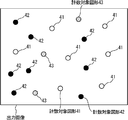
- FIG. 13A illustrates a counting object 31 that is a large nut, a counting object 32 that is a small nut, and a nut (hereinafter, referred to as “medium nut”) having a size between the large nut and the small nut.
- 13B is an output image obtained by applying the captured image of the counting object 33 to the learning device learned from the training image of the nut from the captured image of FIG. 13A.
- the output image in FIG. 13B includes a counting target graphic 41 corresponding to the large nut, a counting target graphic 42 corresponding to the small nut, and a counting target graphic 43 corresponding to the middle nut.
- FIG. 13C is a reference diagram in which the captured image of FIG. 13A and the output image of FIG. 13B are combined.
- the counting object graphic 41 is located at the center of each counting object 31 included in the captured image, and the counting object graphic 42 is located at the center of each counting object 32.
- the counting object graphic 43 is located at the center of each counting object 33.
- the certainty factor acquisition unit 14 has a higher value for each counting target figure included in the output image as the attribute of the counting target figure is closer to the attribute of the teacher figure, and the farther the attribute of the counting target figure is from the attribute of the teacher figure. Get the confidence that is low.
- the attribute may be a color or a shape as described above, or may be another attribute (for example, size or angle).
- the certainty factor is a value indicating the degree of certainty regarding the conversion from the counting target to the counting target graphic. When the ideal conversion is performed, the figure to be counted becomes the same as the teacher figure. For example, FIGS. 10 to 13 show the case where ideal conversion is performed.
- the counting object may be converted into a counting target figure different from the teacher figure, and thus the certainty factor of the counting target figure is acquired according to the difference between the counting target figure and the teacher figure. It will be. Therefore, it may be considered that the higher the certainty factor is, the more the ideal conversion from the counting object to the counting object graphic is performed.
- the figure to be counted included in the output image must be specified in order to obtain the certainty factor.
- the result of the counting unit 15 may be used for specifying the counting target graphic, or the certainty factor acquiring unit 14 may perform the specifying separately from the counting unit 15.
- the obtained value may be, for example, the non-certainty factor (for example, the reciprocal of the certainty factor). Even in that case, it is possible to know the certainty factor as a result by using the non-certainty factor.
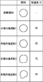
- the certainty factor may be acquired using, for example, (1) shape, (2) size, (3) color attribute, or (4). It may be acquired using an angle.
- the certainty factor of 95% may be acquired for the counting target graphic 1, and the certainty factors of 85%, 75%, and 65% may be acquired for the counting target graphics 2 to 4, respectively.
- the degree to which the shape of the counting target figure deviates from the shape of the teacher figure may be acquired, and the degree of the deviation may be converted into the certainty factor.
- the degree of deviation may be, for example, such that the contour shape of the counting target figure deviates from the contour shape of the teacher figure.
- the certainty factor acquisition unit 14 superimposes the counting target figure for which the certainty factor is to be acquired on the teacher figure so as to best fit it, and then, from each contour point forming the contour of the counting target figure, The distance to the contour of the figure may be acquired, and the degree of deviation may be acquired by adding the distances of the acquired contour points.
- the distance may be the closest distance from the contour point of the counting target graphic to the contour of the teacher graphic.
- the certainty factor may be obtained by substituting the value indicating the degree of deviation thus obtained into the decreasing function.
- the size may be, for example, the area.
- the certainty factor acquisition unit 14 acquires the area of the counting target graphic for which the certainty factor is to be acquired, and acquires the absolute value of the difference between the acquired area and the area of the teacher graphic held in advance. You may. Since the acquired absolute value becomes a value indicating the degree of deviation between the counting target figure for which the confidence factor is to be acquired and the teacher figure, the value indicating the degree of deviation is reduced in the same manner as (1) above.
- the certainty factor may be obtained by substituting it into a function.
- the size may be, for example, a radius or a diameter.
- the certainty factor acquisition unit 14 acquires the radius and diameter of the counting target graphic for which the certainty factor is to be acquired, and compares the acquired radius and diameter with the radius and diameter of the teacher graphic held in advance. By acquiring the absolute value of the difference, a value indicating the degree of deviation between the counting target graphic for which the confidence factor is to be acquired and the teacher graphic may be acquired. After that, the certainty factor may be acquired in the same manner as above.
- the color attribute in the teacher figure may be constant, for example.
- the brightness and hue of the teacher figure may be set to be constant.
- the certainty factor acquisition unit 14 acquires, for example, the color attribute of each pixel forming the counting target graphic for which the certainty factor is to be acquired, and determines the difference between the acquired color attribute and the color attribute of the teacher graphic. You may acquire an absolute value and add the acquired absolute value of the difference of the color attribute for every pixel. Since the addition result is a value indicating the degree of deviation of the color attribute between the counting target figure for which the confidence factor is to be acquired and the teacher figure, the value indicating the degree of deviation is set in the same manner as (1) above. , May be obtained by substituting into the decreasing function.
- the color attribute for example, one or more of lightness, hue, and saturation may be used.
- the certainty factor acquisition unit 14 acquires, for example, the color attribute of each pixel forming the counting target graphic for which the certainty factor is to be acquired, and calculates the difference between the average of the acquired color attributes and the color attribute of the teacher graphic. You may get the absolute value. In that case, the acquired value may be a value indicating the degree of deviation of the color attribute between the counting target graphic and the teacher graphic for which the certainty factor is to be acquired.
- the certainty factor acquisition unit 14 may, for example, acquire the color attribute of each pixel forming the counting target graphic for which the certainty factor is to be acquired, and calculate the variance of the acquired color attributes. Ideally (that is, in the teacher figure), the variance is 0. Therefore, the larger the variance is, the more the color attribute of the counting target figure deviates from the color attribute of the teacher figure. Therefore, the value of the variance becomes a value indicating the degree of deviation of the color attribute between the counting target figure for which the confidence factor is to be acquired and the teacher figure. Therefore, the degree of deviation is determined in the same manner as (1) above.
- the certainty factor may be obtained by substituting the indicated value into the decreasing function.
- the counting objects have a directional shape and are arranged in a certain direction. Shall be arranged along the direction of the counting object.
- the certainty factor acquisition unit 14 acquires, for example, the angle of the counting target graphic for which the certainty factor is to be acquired, and acquires the absolute value of the difference between the acquired angle and the angle of the teacher graphic. Good. Since the absolute value is a value indicating the degree of deviation of the angle between the counting target figure for which the confidence factor is to be acquired and the teacher figure, the value indicating the degree of deviation is calculated in the same manner as (1) above.
- the certainty factor may be obtained by substituting into the decreasing function.
- the angle of the teacher figure or the count target figure may be the angle of the side when the teacher figure or the count target figure is a square or a rectangle, for example.
- the certainty factor may be acquired by using information such as a table that associates the degree of deviation between the counting target graphic for which the certainty factor is acquired and the teacher pattern with the certainty factor.
- the confidence factor may be appropriately normalized so as to take a value in a predetermined range such as a range of 0 to 100% or a range of 0 to 1.
- the counting unit 15 counts the number of counting objects by using the plurality of counting figures included in the output image and the certainty factor. Specifically, the counting unit 15 may count the number of counting target graphics whose confidence factor exceeds the threshold value.
- the threshold is usually predetermined. Note that the threshold may be appropriately adjusted by the operator, for example, by comparing the captured image with the counting result.
- the counting unit 15 specifies a counting target figure by performing pattern matching or the like in the output image using the shape of the teacher figure held in advance, and counts the specified counting target figure using the certainty factor. You can go. It can be considered that the counting target graphic having a low certainty is a result of conversion of a non-counting target object. Therefore, as to the counting target graphic having a low certainty factor, it is possible to prevent the incorrect counting by not counting as described above, and as a result, it is possible to improve the counting accuracy. You can go. It can be considered that the counting target graphic having a low certainty factor, it is possible to prevent the incorrect counting by not counting as described above, and as a result
- the counting unit 15 may perform counting for each counting object graphic having a specific attribute in the output image. For example, in the training image, when a red teacher figure is used for soybeans and a blue teacher figure is used for rice, the counting unit 15 displays the counts related to the red count target figure in the output image. , And counting with respect to the blue count target graphic may be performed respectively. More specifically, the counting unit 15 specifies a counting target graphic having an attribute corresponding to a certain type of counting target in the output image, and identifies the specified counting target graphic and the certainty factor of the counting target graphic. May be used to perform counting for that type of counting object. By repeating such processing for each type of counting object, counting can be performed for all types of counting objects.
- the certainty factor acquisition unit 14 acquires, for example, the certainty factor regarding the counting target graphic having the attribute corresponding to a certain type of the counting target, and has the attribute corresponding to another type. For the figure to be counted, the certainty factor regarding its type may be acquired.
- the certainty factor acquisition unit 14 may obtain the certainty factors for all counting object figures included in the output image for each type of counting object. ..
- the certainty factor acquisition unit 14 sets the soybeans for all counting target figures included in the output image. It is also possible to obtain the certainty factor regarding the rice and the certainty factor regarding the rice. In the acquisition of the certainty factor, it is preferable that the difference between the attribute of the soybean teacher figure and the attribute of the rice teacher figure is reflected in the certainty factor.
- the certainty factor is preferably acquired using the hue of the figure to be counted. Then, the counting unit 15 counts soybeans using the certainty factor of soybeans for each counting target figure included in the output image, and counts rice for the certainty factor of rice for each counting target figure included in the output image. May be used. In this way, counting can be performed for each type of counting object.
- the counting unit 15 may also count the number of objects to be counted of a size that has not been learned by using the attributes and the certainty factors of the figures to be counted included in the output image. In this case, it is preferable that the objects to be counted that have not been learned have the same size. For example, as shown in FIG. 13A, an output image acquired by applying a captured image including a large nut and a small nut that have been learned and a medium nut that has not been learned to a learning device. 13B also includes the counting target graphic 43 corresponding to the middle nut, as shown in FIG. 13B.
- the certainty factor regarding the large nut and the certainty factor regarding the small nut are usually low, and neither the large nut nor the small nut is counted.
- the intermediate attribute between the attributes of the large nut teaching figure and the attributes of the small nut teaching figure is the virtual attribute of the medium nut. It may be set as an attribute of the teacher figure. Then, the certainty factor acquisition unit 14 may calculate the certainty factor for the middle nut for each count target graphic included in the output image by using the attribute of the virtual teacher figure of the middle nut.
- the counting unit 15 may count the middle nut as well as the large nut and the small nut using the certainty factor of the middle nut. For example, in the output image shown in FIG. 13B, if the certainty factor regarding the middle nuts of the three count target figures 43 exceeds the threshold value, the counting unit 15 acquires “3” as the number of middle nuts. .. In addition, the counting unit 15 may count, as the number of medium nuts, the number of counting target figures that are not determined to be large nuts or small nuts by using the certainty factor. Further, the counting unit 15 may count the number of counting target figures in which the certainty factor of the large nut falls within the predetermined range and the certainty factor of the small nut falls within the predetermined range as the number of the medium nuts.
- the output unit 16 outputs the number of counting objects counted by the counting unit 15. When counting is performed for each type of counting object, it is preferable that the number is output for each type.
- this output may be, for example, a display on a display device (for example, a liquid crystal display or an organic EL display), may be transmitted via a communication line to a predetermined device, may be printed by a printer, or may be output by a speaker. It may be audio output, may be stored in a recording medium, or may be delivered to another component.
- the output unit 16 may or may not include a device (for example, a display device or a printer) that outputs.
- the output unit 16 may be realized by hardware, or may be realized by software such as a driver that drives those devices.
- Step S101 The captured image acquisition unit 12 determines whether to acquire a captured image. If the captured image is to be acquired, the process proceeds to step S102. If not, the process of step S101 is repeated until it is determined that the captured image is to be acquired. Note that, for example, the captured image acquisition unit 12 may determine to acquire the captured image according to an instruction from the operator.
- Step S102 The captured image acquisition unit 12 acquires a captured image of the counting object.
- the acquired captured image may be stored in a recording medium (not shown).
- Step S103 The output image acquisition unit 13 acquires the output image corresponding to the captured image by applying the captured image acquired in Step S102 to the learning device stored in the storage unit 11.
- the acquired output image may be stored in a recording medium (not shown).
- the counting unit 15 identifies the counting target figure in the output image.
- the specification of the counting target graphic may be, for example, specification of a position or an area in the output image in which the counting target graphic is included.
- Step S105 The certainty factor acquisition unit 14 acquires the certainty factor for each figure to be counted specified in step S104.
- the certainty factor acquisition unit 14 determines, for example, for each of all the identified counting figures, the confidence figure for each teacher figure corresponding to the type of counting object. You may get the degree. That is, when there are two types of counting objects, two confidence factors may be acquired for one counting object graphic.
- the counting unit 15 acquires the number of counting objects, that is, the number of objects to be counted, using the counting target graphic specified in the output image and the certainty factor acquired by the certainty factor acquiring unit 14. .. If a plurality of types of counting objects are included in the captured image, the counting unit 15 may acquire the number of counting objects for each type.
- Step S107 The output unit 16 outputs the number of counting objects acquired by the counting unit 15. Then, the process returns to step S101.
- the certainty factor acquisition unit 14 acquires the certainty factor for each counting target graphic specified by the counting unit 15 has been described, but the certainty factor may not be so.
- the certainty factor acquisition unit 14 may also specify the counting target graphic in the output image.
- the order of processing in the flowchart of FIG. 3 is an example, and the order of each step may be changed as long as the same result can be obtained. Note that in the flowchart of FIG. 3, the processing is ended by powering off or interruption for aborting the processing.
- Step S201 The training image receiving unit 21 determines whether or not a plurality of sets of training input images and training output images have been received. Then, if a plurality of sets of the training input image and the training output image are received, the process proceeds to step S202. If not, the process of step S201 is repeated until they are received.
- Step S202 The learning device manufacturing unit 22 manufactures a learning device by machine learning using the training image received in step S201.
- Step S203 The learning device output unit 23 outputs the learning device manufactured in step S202. In this way, a series of processes for manufacturing the learning device is completed. Note that the order of processing in the flowchart of FIG. 4 is an example, and the order of each step may be changed as long as the same result can be obtained.
- the user prepares a training input image shown in FIG. 5A, in which soybean, which is a counting object, is photographed. Also, the user manually arranges a black disk shape, which is a teacher figure, near the center of the soybean included in the training input image by using image processing software or the like, as shown in FIG. 5C. .. Then, a training output image having a plurality of teacher figures arranged at the position of the counting object is generated as shown in FIG. 5B. By repeating such work, the user prepares a plurality of sets of training images. Then, the prepared plurality of sets of training images are input to the learning device manufacturing apparatus 2 to start learning.
- the training image acceptance unit 21 accepts a plurality of sets of training images (step S201), and the learning device manufacturing unit 22 manufactures a learning device using the plurality of sets of training images (step S202).
- the learning device manufactured in this way is accumulated in a recording medium (not shown) by the learning device output unit 23 (step S203).
- the learning device stored in the recording medium is stored in the storage unit 11 of the counting device 1.
- the operator of the counting device 1 operates the counting device 1 so that the captured images of a plurality of soybeans are acquired by the same optical system as that when the training input image is captured.
- the captured image acquisition unit 12 captures an image according to the operation, and acquires the captured image shown in FIG. 10A (steps S101 and S102).
- the output image acquisition unit 13 receives the captured image from the captured image acquisition unit 12, uses each pixel of the captured image as an input layer of the learning device stored in the storage unit 11, and performs calculation of each layer to output the output layer. Information, that is, an output image is acquired (step S103).
- the output image is assumed to be the one shown in FIG. 10B.
- the counting unit 15 uses a black circle, which is a teacher figure that is held in advance, as a pattern in the output image, and specifies a counting target figure similar to that (step S104). Note that the identification may be performed by identifying a figure having a similarity with the pattern equal to or more than a threshold.
- the certainty factor acquisition unit 14 acquires the certainty factor for each counting target graphic specified by the counting unit 15 (step S105). As a result, the certainty factor is acquired for each figure to be counted.
- the counting unit 15 counts the number of figures to be counted whose acquired certainty factor is larger than a predetermined threshold value. For example, when the N certainty factors are acquired by the certainty factor acquisition unit 14, by counting the number (M) of the certainty factors that exceed the threshold value among the N certainty factors, the certainty factors can be increased. It is possible to acquire the number (M) of counting target figures that exceed the threshold value. Note that N and M are integers of 0 or more, and N ⁇ M. In the case of FIG.
- step S106 it is assumed that there are 80 counting target graphics having a certainty factor exceeding the threshold value, and 80 of them are acquired by the counting unit 15 (step S106). Then, the output unit 16 outputs the number “80” of counting objects (step S107). In this way, the number of counting objects included in the captured image can be easily and accurately counted.
- FIG. 15A to 15F are actual images showing a training image used for learning by the learning device manufacturing apparatus 2 according to the present embodiment, and a captured image and an output image used for counting by the counting device 1.
- FIG. 15A is an input image for training in which azuki beans (red beans) which are the objects to be counted are photographed.
- FIG. 15B is a training output image including a white disk-shaped teacher figure arranged at the position of the counting object in FIG. 15A.
- FIG. 15C is a reference diagram in which the training input image of FIG. 15A and the training output image of FIG. 15B are combined. A plurality of sets of such training input images and training output images were prepared, and the learning device manufacturing apparatus 2 was made to perform machine learning to manufacture a learning device used for counting red beans.
- FIG. 15F is a reference diagram in which the captured image of FIG. 15D and the output image of FIG. 15E are combined.
- the count target figure included in the output image should be a white perfect circle, as in the teacher figure of FIG. 15B, but in reality, as shown in FIG.
- the figure to be counted has a shape other than a perfect circle.
- the certainty factor is acquired by using the measure or the like, and the number of figures to be counted, that is, the number of counting objects is counted using the certainty factor. In this way, the number of counting objects can be counted.
- the learning device is used to convert the counting object included in the captured image into the counting object graphic, and count the number of the counting object graphic after the conversion. By doing so, the number of counting objects can be counted with high accuracy. This is because by using an appropriate learning result, the counting object can be converted into the counting object graphic with high accuracy as shown in FIG. 15E and the like. Further, by counting the figure to be counted using the certainty factor acquired for each figure to be counted, it is possible to further improve the accuracy. Further, when learning is performed by using different teacher figures for each type of counting object, it is possible to count the number of counting objects for each type by using the attribute of the counting object figure. Become. Further, when the type is a type related to the size, it becomes possible to count the counting target object that has not been learned.
- the learning device manufacturing apparatus 2 it is possible to generate the learning device used for counting the counting object by using the plurality of training images. Further, when using a teacher figure having a different attribute for each type of counting object, only one type of counting object and one type of corresponding teacher are included in the set of the training input image and the training output image. By including only the figure and, the learner can be manufactured by learning less training images.
- the counting unit 15 may count the total number of counting target graphics included in the output image, that is, the number of counting target objects, without using the certainty factor.
- the counting device 1 may not include the certainty factor acquisition unit 14.
- the learning device may be, for example, the learning result of SVM or SVR.
- the case where the learning device is a learning result other than the neural network will be briefly described.
- the learning device is the learning result of SVM.
- the input may be the value of each pixel included in the area 81 shown in FIG. 16A, and the pixel value of the representative point (x mark) of the area 82 shown in FIG.
- the 16B may be the output.
- the learning device manufacturing unit 22 performs learning by setting the output to “1” when the pixel of the representative point is black and the output to “0” (or “ ⁇ 1”) when the pixel is white. May be. Note that the position of the area 81 in the training input image corresponds to the position of the area 82 in the training output image.
- the representative point of the area 82 may be, for example, the center point, or may be a point representing the other area 82. In FIG. 16B, the representative point is the center point.
- the output is usually binary, so the training output image in FIG. 16B may be a binary image.
- the learning device manufacturing unit 22 performs learning while shifting the positions of the regions 81 and 82 pixel by pixel. Therefore, a lot of learning can be performed by using one set of the training input image and the training output image. Further, the learning is performed using a plurality of sets of a training input image and a training output image.
- the areas 81 and 82 may be set to a size such that one counting object is included in the areas 81 and 82, for example.
- the captured image When the captured image is applied to the learning device, it is applied to each area similar to the area 81. For example, when a predetermined area is arranged at a certain position of the captured image and each pixel of the predetermined area is input to the learning device, 1 or 0 (or -1) is output. According to the output, the output image acquisition unit 13 sets the pixel of the representative point in the area corresponding to the predetermined area in the output image to black or white. By performing such processing while shifting the position of the predetermined area in the captured image pixel by pixel, an output image including the count target graphic can be obtained. The subsequent processing is the same as when the learning device that is the learning result of the neural network is used.
- the pixel value of the N1 ⁇ N2 area around a certain pixel (pixel at the representative point) in the training input image is input, and the pixel at that representative point is set as the pixel value.
- the pixel value of the N1 ⁇ N2 region in the captured image is input to the learning device, an output indicating white or black is acquired, and the pixel value corresponding to the representative point of the N1 ⁇ N2 region in the output image is set.
- the output image may be acquired by performing the setting of white or black according to the output while shifting the N1 ⁇ N2 region by one pixel.
- N1 and N2 are usually integers of 3 or more.
- the counting target may be, for example, a manufacturing target, a production target, a capture target, a transport target, or other counting target. May be
- the product to be manufactured may be, for example, a product or food.
- the product is not particularly limited, but may be, for example, a screw, a bolt, a rod, a home appliance, a stationery (for example, a clip, a rubber band, etc.), a toothpick, or an automobile part.
- the food is not particularly limited, but may be, for example, confectionery, sausage, bread, noodles, canned food, bottles, or packaged food products.
- the production target can be, for example, agricultural products, livestock products, or the like.
- the agricultural product is not particularly limited, but may be beans, rice, vegetables, fruits, or seeds, for example.
- the livestock product is not particularly limited, and may be sheep, goat, cow, chicken, egg, cheese or the like.
- the target to be captured may be, for example, marine products or wild birds and beasts.
- the marine product is not particularly limited, but may be, for example, fish, shrimp, crab, shellfish, or the like.
- the wild bird or beast is not particularly limited, but may be, for example, a bird to be hunted or a mammal to be hunted.
- the object to be transported is not particularly limited, but may be a box such as a cardboard box or a container, for example.
- counting objects are not particularly limited, but may be, for example, humans, automobiles, cells, bacteria, viruses, microorganisms, microbubbles, nanobubbles, powder, coins, birds, insects, or the like.
- the counting object is, for example, a cell, a bacterium, a virus, a microorganism, a micro bubble, a nano bubble, or a powder
- the captured image may be, for example, a microscope image captured using a microscope. .
- the microscope is not particularly limited, but may be, for example, an optical microscope, an electron microscope, an X-ray microscope, or the like.
- the counting device 1 and the learning device manufacturing device 2 may be stand-alone devices or server devices in a server/client system.
- the output unit, the acquisition unit, and the reception unit may output the information, acquire the information, or receive the information via the communication line.
- each process or each function may be realized by being centralized by a single device or a single system, or distributed by a plurality of devices or multiple systems. It may be realized by
- one of the constituent elements when information is exchanged between the respective constituent elements, for example, when two constituent elements for exchanging the information are physically different, one of the constituent elements is used. It may be performed by outputting the information and receiving the information by the other component, or when the two components that transfer the information are physically the same, one component The processing may be performed by shifting from the processing phase corresponding to the above to the processing phase corresponding to the other component.
- information related to processing executed by each component for example, information that each component has received, acquired, selected, generated, transmitted, or received.
- Information such as thresholds, mathematical expressions, addresses, etc. used by each component in processing may be held in a recording medium (not shown) temporarily or for a long period of time, even if not specified in the above description.
- the storage of information in the recording medium (not shown) may be performed by each component or the storage unit (not shown).
- the reading of information from the recording medium (not shown) may be performed by each component or the reading unit (not shown).
- the information used in each component or the like for example, the information such as the threshold value or the address used in the process of each component or various setting values may be changed by the user, Even if not explicitly stated in the description, the user may or may not be able to change the information as appropriate.
- the change is realized by, for example, a reception unit (not shown) that receives a change instruction from the user and a change unit (not shown) that changes the information according to the change instruction. May be.
- the reception of the change instruction by the reception unit (not shown) may be reception from an input device, reception of information transmitted via a communication line, or reception of information read from a predetermined recording medium. ..
- the two or more constituent elements included in the counting apparatus 1 may physically have a single device. , Or may have separate devices. The same applies to the learning device manufacturing apparatus 2.
- each component may be configured by dedicated hardware, or a component that can be implemented by software may be implemented by executing a program.
- each component can be realized by a program execution unit such as a CPU reading and executing a software program recorded in a recording medium such as a hard disk or a semiconductor memory.
- the program execution unit may execute the program while accessing the storage unit or the recording medium.
- the software that implements the counting device 1 in the above embodiment is the following program. That is, this program is a training input image that is an image of a plurality of counting objects of the same shape, and an output image for training that includes a teacher figure arranged at each position of the plurality of counting objects.
- a captured image acquisition unit that acquires captured images of a plurality of counting objects to the computer that can access a storage unit that stores a learning device that is learned by using a plurality of sets, the captured images to the learning device.
- the software that realizes the learning device manufacturing apparatus 2 in the above embodiment is the following program.
- this program is used for the computer to output a training input image, which is an image in which a plurality of counting objects of the same shape are photographed, and a training output including a teacher figure arranged at each position of the counting objects.
- a training image receiving step of receiving a plurality of sets of images, a learning device manufacturing step of manufacturing a learning device by learning a plurality of sets of a training input image and a training output image, and a learning device of outputting the learning device This is a program for executing the output step and.
- the functions realized by the program do not include the functions that can be realized only by hardware.
- a function that can be realized only by hardware such as a modem or an interface card in an acquisition unit that acquires information, a reception unit that receives information, and an output unit that outputs information is at least included in the functions realized by the program. Absent.
- this program may be executed by being downloaded from a server or the like, and the program recorded on a predetermined recording medium (for example, an optical disk such as a CD-ROM, a magnetic disk, or a semiconductor memory) may be read out. May be performed by. Further, this program may be used as a program that constitutes a program product.
- a predetermined recording medium for example, an optical disk such as a CD-ROM, a magnetic disk, or a semiconductor memory
- the computer that executes this program may be singular or plural. That is, centralized processing may be performed or distributed processing may be performed.
- FIG. 17 is a schematic diagram showing an example of the external appearance of a computer that executes the above program to realize the counting device 1 and the learning device manufacturing device 2 according to the above-described embodiment.
- the above embodiment can be realized by computer hardware and a computer program executed on the computer hardware.
- the computer system 900 includes a computer 901 including a CD-ROM drive 905, a keyboard 902, a mouse 903, and a monitor 904.
- FIG. 18 is a diagram showing the internal configuration of the computer system 900.
- a computer 901 is connected to an MPU (Micro Processing Unit) 911, a ROM 912 for storing a program such as a boot-up program, and an instruction of an application program in addition to a CD-ROM drive 905.
- MPU Micro Processing Unit
- ROM 912 for storing a program such as a boot-up program
- a RAM 913 that temporarily stores and provides a temporary storage space
- a hard disk 914 that stores application programs, system programs, and data
- a bus 915 that interconnects the MPU 911, ROM 912, and the like.
- the computer 901 may include a network card (not shown) that provides a connection to a LAN, WAN, or the like.
- a program that causes the computer system 900 to execute the functions of the counting device 1 and the learning device manufacturing device 2 according to the above-described embodiment is stored in the CD-ROM 921, inserted into the CD-ROM drive 905, and transferred to the hard disk 914. Good.
- the program may be transmitted to the computer 901 via a network (not shown) and stored in the hard disk 914.
- the program is loaded into the RAM 913 when it is executed.
- the program may be loaded directly from the CD-ROM 921 or the network. Further, the program may be read into the computer system 900 via another recording medium (for example, a DVD or the like) instead of the CD-ROM 921.
- the program does not necessarily include the operating system (OS) that causes the computer 901 to execute the functions of the counting device 1 and the learning device manufacturing apparatus 2 according to the above-described embodiments, or a third-party program.
- the program may include only a part of an instruction that calls an appropriate function or module in a controlled manner to obtain a desired result. How the computer system 900 operates is well known and will not be described in detail.
- the counting device and the like according to the present invention it is possible to obtain an effect that the counting object can be counted with high accuracy, and it is useful as a device for counting the counting object.
Landscapes
- Engineering & Computer Science (AREA)
- Theoretical Computer Science (AREA)
- Physics & Mathematics (AREA)
- General Physics & Mathematics (AREA)
- Evolutionary Computation (AREA)
- Artificial Intelligence (AREA)
- Multimedia (AREA)
- Data Mining & Analysis (AREA)
- Software Systems (AREA)
- Life Sciences & Earth Sciences (AREA)
- General Health & Medical Sciences (AREA)
- Health & Medical Sciences (AREA)
- General Engineering & Computer Science (AREA)
- Computing Systems (AREA)
- Computer Vision & Pattern Recognition (AREA)
- Biomedical Technology (AREA)
- Molecular Biology (AREA)
- Mathematical Physics (AREA)
- Computational Linguistics (AREA)
- Biophysics (AREA)
- Medical Informatics (AREA)
- Bioinformatics & Cheminformatics (AREA)
- Bioinformatics & Computational Biology (AREA)
- Evolutionary Biology (AREA)
- Databases & Information Systems (AREA)
- Biodiversity & Conservation Biology (AREA)
- Image Analysis (AREA)
- Image Processing (AREA)
Abstract
【課題】計数対象物を精度高く計数することができる計数装置を提供する。 【解決手段】計数装置1は、同じ形状の複数の計数対象物が撮影された画像である訓練用入力画像と、複数の計数対象物のそれぞれの位置に配置された教師図形を含む訓練用出力画像との組を複数用いて学習された学習器が記憶される記憶部11と、複数の計数対象物の撮影画像を取得する撮影画像取得部12と、撮影画像を学習器に適用することによって、撮影画像に含まれる各計数対象物が計数対象図形に変換された出力画像を取得する出力画像取得部13と、出力画像に含まれる複数の計数対象図形を用いて計数対象物の個数を計数する計数部15と、計数部15によって計数された計数対象物の個数を出力する出力部16とを備える。
Description
本発明は、計数対象の個数をカウントする計数装置等に関する。
従来、計数対象物の集合体の撮影画像において、撮影ガイドを用いて自動的に生成された形状モデルを用いたマッチング処理を行うことによって、計数対象を計数する方法がある(例えば、特許文献1参照)。
しかしながら、従来の計数方法においては、形状モデルを用いたマッチング処理を行うため、形状モデルが適切に生成されなかった場合には、計数の精度が低くなる可能性があるという問題があった。また、複数の計数対象物の形状に微小な違いがある場合には、計数の精度が低くなると考えられる。
本発明は、上記課題を解決するためになされたものであり、計数の精度を向上させることができる計数装置等を提供することを目的とする。
上記目的を達成するため、本発明による計数装置は、同じ形状の複数の計数対象物が撮影された画像である訓練用入力画像と、複数の計数対象物のそれぞれの位置に配置された教師図形を含む訓練用出力画像との組を複数用いて学習された学習器が記憶される記憶部と、複数の計数対象物の撮影画像を取得する撮影画像取得部と、撮影画像を学習器に適用することによって、撮影画像に含まれる各計数対象物が計数対象図形に変換された出力画像を取得する出力画像取得部と、出力画像に含まれる複数の計数対象図形を用いて計数対象物の個数を計数する計数部と、計数部によって計数された計数対象物の個数を出力する出力部と、を備えたものである。
このような構成により、学習器を用いて撮影画像に含まれる計数対象物を計数対象図形に変換することによって、計数対象物の個数を取得することができるようになる。また、計数対象物を計数対象図形に変換する際の精度が高いことにより、より高精度に計数対象物を計数することが可能となる。例えば、形状に微小な違いのある計数対象物の訓練用入力画像を用いて学習された学習器を用いることによって、形状に微小な違いのある計数対象物についても、適切に計数することができるようになる。
また、本発明による計数装置では、出力画像に含まれる計数対象図形ごとに、計数対象図形の属性が教師図形の属性に近いほど高い値となる確信度を取得する確信度取得部をさらに備え、計数部は、確信度が閾値を超える計数対象図形の個数を計数してもよい。
このような構成により、計数対象図形から取得される確信度を用いることによって、より精度の高い計数を行うことができるようになる。また、例えば、閾値を適切に調整することにより、複数の計数対象物の形状に微小な違いがあったとしても、適切な計数が行われるようにすることもできる。
また、本発明による計数装置では、計数対象物は、大きさに関する複数の種類が存在し、学習器は、計数対象物の大きさごとに異なる属性の教師図形を用いて学習されたものであり、計数部は、出力画像に含まれる計数対象図形の属性及び確信度を用いることによって、学習していない大きさの計数対象物についても個数を計数してもよい。
このような構成により、学習を行っていない計数対象物についても、個数を計数することができるようになる。
また、本発明による学習器製造装置は、同じ形状の複数の計数対象物が撮影された画像である訓練用入力画像と、複数の計数対象物のそれぞれの位置に配置された教師図形を含む訓練用出力画像との組を複数受け付ける訓練画像受付部と、訓練用入力画像と訓練用出力画像との複数の組を学習することによって学習器を製造する学習器製造部と、学習器を出力する学習器出力部と、を備えたものである。
このような構成により、計数対象物の計数に用いる学習器を製造することができるようになる。
また、本発明による学習器製造装置では、計数対象物は複数種類存在し、訓練画像受付部は、計数対象物の種類ごとに異なる属性の教師図形を含む訓練用出力画像を受け付けてもよい。
このような構成により、製造された学習器を用いることによって、複数種類の計数対象に関する計数を行うことができるようになる。
また、本発明による学習器製造装置では、訓練画像受付部は、計数対象物の種類ごとの訓練用入力画像と訓練用出力画像との組を受け付けてもよい。
このような構成により、複数種類の計数対象物を含む1個の訓練用入力画像を用いて学習を行う場合よりも、より少ない訓練用入力画像と訓練用出力画像との組で学習器を生成することができるようになる。
また、本発明による学習器製造装置では、計数対象物の種類は、計数対象物の大きさに関する種類であってもよい。
このような構成により、製造された学習器を用いることによって、複数の大きさごとに計数対象物の計数を行うことができるようになる。
また、本発明による学習器製造装置では、教師図形は、方向性のない図形であってもよい。
このような構成により、教師図形の向きを考慮しなくてよいため、訓練用出力画像の用意が簡単になると共に、少ない訓練用の画像を用いて効率よく学習を行うことができるようになる。
また、本発明による学習器製造装置では、教師図形は、訓練用入力画像における計数対象物の方向に応じて方向が設定された、方向性を有する図形であってもよい。
このような構成により、例えば、重力等の影響によって方向が揃う計数対象物について、より精度の高い計数を実現することができるようになる。例えば、計数装置において、計数対象図形が揃うと考えられる方向以外の角度の計数対象図形については計数しないようにすることによって、計数対象物の背景などに、計数対象図形と類似した形状の物体が含まれている場合であっても、そのような形状の物体の角度が計数対象図形の角度と異なっているときには、その物体を誤って計数しないようにすることができ、より精度の高い計数を実現することができるようになる。
また、本発明による学習器は、同じ形状の複数の計数対象物が撮影された画像である訓練用入力画像と、複数の計数対象物のそれぞれの位置に配置された教師図形を含む訓練用出力画像との複数の組の学習結果の学習器であって、複数の計数対象物の撮影画像が適用されると、撮影画像に含まれる各計数対象物が計数対象図形に変換された出力画像を取得することができる、ものである。
また、本発明による計数方法は、複数の計数対象物の撮影画像を取得する撮影画像取得ステップと、撮影画像を、同じ形状の複数の計数対象物が撮影された画像である訓練用入力画像と、複数の計数対象物のそれぞれの位置に配置された教師図形を含む訓練用出力画像との組を複数用いて学習された学習器に適用することによって、撮影画像に含まれる各計数対象物が計数対象図形に変換された出力画像を取得する出力画像取得ステップと、出力画像に含まれる複数の計数対象図形を用いて計数対象物の個数を計数する計数ステップと、計数ステップにおいて計数された計数対象物の個数を出力する出力ステップと、を備えたものである。
また、本発明による学習器製造方法は、同じ形状の複数の計数対象物が撮影された画像である訓練用入力画像と、複数の計数対象物のそれぞれの位置に配置された教師図形を含む訓練用出力画像との組を複数受け付ける訓練画像受付ステップと、訓練用入力画像と訓練用出力画像との複数の組を学習することによって学習器を製造する学習器製造ステップと、学習器を出力する学習器出力ステップと、を備えたものである。
本発明による計数装置等によれば、精度の高い計数を実現することができる。
以下、本発明による計数装置及び学習器製造装置について、実施の形態を用いて説明する。なお、以下の実施の形態において、同じ符号を付した構成要素及びステップは同一または相当するものであり、再度の説明を省略することがある。本実施の形態による計数装置は、訓練用入力画像と訓練用出力画像とを用いて学習された学習器を用いて、撮影画像に含まれる計数対象物を図形に変換することによって、計数対象物の個数をカウントするものである。また、本実施の形態による学習器製造装置は、訓練用入力画像と訓練用出力画像との複数の組を用いて学習を行うことにより、計数対象物の計数に用いられる学習器を製造することができるものである。
図1は、本実施の形態による計数装置1の構成を示すブロック図である。本実施の形態による計数装置1は、記憶部11と、撮影画像取得部12と、出力画像取得部13と、確信度取得部14と、計数部15と、出力部16とを備える。計数装置1は、例えば、パーソナルコンピュータであってもよく、スマートフォンやタブレット端末、PDA(Personal Digital Assistant)等などの携帯可能な情報処理端末であってもよく、計数処理を行う専用の装置であってもよく、サーバ等であってもよい。
記憶部11では、学習器が記憶される。この学習器は、同じ形状の複数の計数対象物が撮影された画像である訓練用入力画像と、その複数の計数対象物のそれぞれの位置に配置された教師図形を含む訓練用出力画像との組を複数用いて学習されたものである。訓練用入力画像と訓練用出力画像との組を訓練画像と呼ぶこともある。学習器は、例えば、ニューラルネットワーク(NN:Neural Network)の学習結果であってもよく、サポートベクターマシン(SVM:Support Vector Machine)やサポートベクター回帰(SVR:Support Vector Regression)の学習結果であってもよく、または、それ以外の機械学習の学習結果であってもよい。
ニューラルネットワークは、例えば、畳み込みニューラルネットワーク(CNN:Convolutional Neural Network)であってもよく、それ以外のニューラルネットワーク(例えば、全結合層から構成されるニューラルネットワーク等)であってもよい。畳み込みニューラルネットワークとは、1以上の畳み込み層を有するニューラルネットワークのことである。また、ニューラルネットワークが少なくとも1個の中間層(隠れ層)を有する場合には、そのニューラルネットワークの学習は、深層学習(ディープラーニング、Deep Learning)であると考えてもよい。また、機械学習にニューラルネットワークを用いる場合において、そのニューラルネットワークの層数、各層におけるノード数、各層の種類(例えば、畳み込み層、全結合層など)等については、適宜、選択したものを用いてもよい。なお、入力層と出力層のノード数は、通常、訓練画像に含まれる訓練用入力画像と訓練用出力画像とによって決まることになる。本実施の形態では、学習器がCNNの学習結果である場合について主に説明し、それ以外の場合については後述する。
なお、学習器が記憶部11で記憶されているとは、例えば、学習器そのもの(例えば、入力に対して値を出力する関数や学習結果のモデル等)が記憶されていることであってもよく、学習器を構成するために必要なパラメータ等の情報が記憶されていることであってもよい。後者の場合であっても、そのパラメータ等の情報を用いて学習器を構成できるため、実質的に学習器が記憶部11で記憶されていると考えることができるからである。本実施の形態では、学習器そのものが記憶部11で記憶されている場合について主に説明する。
記憶部11に学習器が記憶される過程は問わない。例えば、記録媒体を介して学習器が記憶部11で記憶されるようになってもよく、通信回線等を介して送信された学習器が記憶部11で記憶されるようになってもよい。記憶部11での記憶は、RAM等における一時的な記憶でもよく、または、長期的な記憶でもよい。記憶部11は、所定の記録媒体(例えば、半導体メモリや磁気ディスク、光ディスクなど)によって実現されうる。
ここで、学習器の生成について説明する。図2は、本実施の形態による学習器製造装置2の構成を示すブロック図である。本実施の形態による学習器製造装置2は、訓練画像受付部21と、学習器製造部22と、学習器出力部23とを備える。学習器製造装置2は、通常、学習を行う情報処理装置であるが、例えば、携帯可能な情報処理端末等の汎用の装置であってもよく、学習を行う専用の装置であってもよく、サーバ等であってもよい。
訓練画像受付部21は、同じ形状の複数の計数対象物が撮影された画像である訓練用入力画像と、その複数の計数対象物のそれぞれの位置に配置された教師図形を含む訓練用出力画像との組を複数受け付ける。
複数の計数対象物は、上記のように、同じ形状であることが好適である。なお、同じ形状とは、厳密に同じ形状であってもよく、実質的に同じ形状であってもよい。また、複数の計数対象物は、同じ大きさであってもよい。同じ大きさとは、厳密に同じ大きさであってもよく、実質的に同じ大きさであってもよい。例えば、計数対象物が、農作物などの自然物である場合には、厳密には各計数対象物の形状や大きさに微小な差が存在することもあり得るが、実質的に同じ形状、同じ大きさと判断できるのであれば、同じ形状、同じ大きさと考えてもよい。具体的には、大豆や米、植物の種などは、同じ形状及び大きさであると考えてもよい。また、例えば、計数対象物が、ネジやボルトなどの人工物である場合でも、自然物よりは程度は小さいと考えられるが、厳密には各計数対象物の形状や大きさに僅かな差が存在することもあり得る。そのような場合であっても、実質的に同じ形状、同じ大きさと判断できるのであれば、同じ形状、同じ大きさと考えてもよい。なお、同じ大きさかどうかは、通常、画素数に応じた大きさによって判断されることになる。また、訓練用入力画像に含まれる複数の計数対象物には、計数したい計数対象物の形状や大きさのバリエーションが含まれていることが好適である。例えば、上記のように、計数対象物が自然物である場合には、形状や大きさに微小な違いが含まれていることもあるが、そのような微小な違いを含む種々の計数対象物が訓練用入力画像に含まれていることが好適である。そのようにすることによって、そのような違いの影響を受けない計数を実現できるからである。なお、本実施の形態では,複数の計数対象物が同じ形状及び同じ大きさである場合について主に説明する。
教師図形は、通常、計数対象物よりも小さい図形であることが好適である。そのようにすることで、計数対象物の一部が重なっている場合であっても、計数対象物の全体が重なっているのでなければ、後述するように、計数対象物を計数対象図形に変換できうるからである。また、教師図形は、計数対象物の中心に相当する位置に配置されることが好適であるが、そうでなくてもよい。ただし、計数対象物の中心に相当する位置以外の位置に教師図形を配置する場合であっても、計数対象物のあらかじめ決められた位置に相当する位置に教師図形が配置されることが好適である。
教師図形の形状は問わないが、例えば、教師図形は、方向性のない図形であってもよい。方向性のない図形は、画像上において回転しても変形しない図形であり、例えば、円環形状、円盤形状等であってもよい。通常は、方向性のない教師図形が用いられることが好適である。一方、教師図形は、例えば、方向性を有する図形であってもよい。方向性を有する教師図形は、例えば、三角形状、四角形状、多角形状、線形状等であってもよい。教師図形が方向性を有する図形である場合には、訓練用出力画像に含まれる各教師図形は、訓練用入力画像における各計数対象物の方向に応じて方向が設定されてもよい。計数対象物が、例えば、爪楊枝や鉛筆などのように、撮影画像において線状である場合には、例えば、方向性のある線形状の教師図形が用いられてもよい。その場合には、例えば、線状の計数対象物の長手方向が、教示図形の長手方向となるように教師図形が配置されてもよい。また、計数対象物が、方向性のある形状であり、かつ、一定の方向に揃うようになっている場合には、例えば、方向性のある教師図形が用いられてもよい。その場合には、例えば、計数対象物の形状に応じて、教師図形の向き(角度)が決まることが好適である。例えば、計数対象物が正方形状である場合には、正方形状の教師図形の各辺の方向が計数対象物の各辺に揃うように、計数対象物の中心に相当する位置に教師図形が配置されてもよい。なお、上記のように、計数対象物は、一定の方向に揃うようになっているため、計数対象物ごとの角度の違いが十分小さいと考えられる場合には、その揃った方向に沿った同じ角度の教師図形がそれぞれ配置されてもよい。
複数種類の計数対象物について計数を行う場合には、訓練画像受付部21は、計数対象物の種類ごとに異なる属性の教師図形を含む訓練用出力画像を受け付けてもよい。計数対象物の種類は、例えば、形状に関する種類であってもよく、大きさに関する種類であってもよく、色に関する種類であってもよく、その他の種類であってもよく、または、それらの任意の2以上の組み合わせであってもよい。形状及び大きさの異なる計数対象物としては、例えば、大豆と米などがある。また、大きさの異なる計数対象物としては、例えば、大きさの異なるナットなどがある。また、色の異なる計数対象物としては、例えば、通常の大豆と青大豆などがある。教師図形の属性は、例えば、色(例えば、色相、彩度、明度の少なくとも1以上など)であってもよく、形状であってもよく、その他の属性であってもよい。例えば、計数対象物として、大豆と米がある場合には、大豆には赤色の教師図形が用いられ、米には青色の教師図形が用いられてもよい。
複数種類の計数対象物について計数を行う場合には、訓練画像受付部21は、計数対象物の種類ごとの訓練用入力画像と訓練用出力画像との組を受け付けてもよい。すなわち、1個の組の訓練画像には、1種類の計数対象物のみを含む訓練用入力画像と、その計数対象物に対応する属性の教師図形のみを含む訓練用出力画像とが含まれていてもよい。例えば、計数対象物として大豆と米がある場合には、訓練画像受付部21は、大豆に関する訓練用入力画像と訓練用出力画像との複数の組と、米に関する訓練用入力画像と訓練用出力情報との複数の組とを受け付けてもよい。このように、計数対象物の種類ごとの訓練用入力画像と訓練用出力画像との組を用いて学習を行う方が、複数種類の計数対象物の混ざった訓練用入力画像と訓練用出力情報との組を用いて学習を行うよりも、より少ない訓練画像によって適切な学習器を生成することができる。
また、後述する確信度を算出するためには、教師図形は、あらかじめ決められた形状や、色などの属性を有していることが好適である。例えば、教師図形の形状と大きさは決まっていてもよい。また、例えば、教師図形の色属性(例えば、明度や色相、彩度)はあらかじめ決められていてもよい。その場合に、例えば、教師図形を構成する各画素の色属性はすべて同じであってもよい。
図5~図8は、訓練画像の一例を示す図である。図5Aは、大豆である計数対象物の訓練用入力画像であり、図5Bは、図5Aの訓練用入力画像の大豆の位置にそれぞれ配置された、方向性のない教師図形(すなわち、円板形状の教師図形)を含む訓練用出力画像である。図5Cは、図5Aの訓練用入力画像と、図5Bの訓練用出力画像とを合成した参考図である。図5Cで示されるように、計数対象物の中心位置に、各教師図形が配置されている。
図6Aは、断面が正方形状である、積み重ねられた複数の乾麺である計数対象物の端部が撮影された訓練用入力画像であり、図6Bは、図6Aの訓練用入力画像の乾麺の位置にそれぞれ配置された、方向性を有する教師図形を含む訓練用出力画像である。なお、図6Bにおいては、方向性を有する教師図形(すなわち、正方形状の教師図形)が用いられているため、各教師図形は、計数対象物である棒状の乾麺の端部において、計数対象物の正方形状と各辺が揃う方向で配置されている。図6Cは、図6Aの訓練用入力画像と、図6Bの訓練用出力画像とを合成した参考図である。図6Cで示されるように、計数対象物の中心位置に、各教師図形が、計数対象物と向きが揃うように配置されている。
図7Aは、爪楊枝である計数対象物の訓練用入力画像であり、図7Bは、図7Aの訓練用入力画像の爪楊枝の位置にそれぞれ配置された、方向性を有する教師図形(すなわち、線状の教師図形)を含む訓練用出力画像である。図7Cは、図7Aの訓練用入力画像と、図7Bの訓練用出力画像とを合成した参考図である。図7Cで示されるように、計数対象物の中心位置に、計数対象物と同じ方向となるように、各教師図形が配置されている。
図8A,図8Bは、ナットである計数対象物の訓練用入力画像である。なお、図8Aの訓練用入力画像のナットの方が、図8Bの訓練用入力画像のナットよりもサイズが大きいものとする。ここでは、図8Aのナットを「大ナット」と呼び、図8Bのナットを「小ナット」と呼ぶことにする。図8Cは、図8Aの訓練用入力画像の大ナットの位置にそれぞれ配置された、方向性のない教師図形を含む訓練用出力画像であり、図8Dは、図8Bの訓練用入力画像の小ナットの位置にそれぞれ配置された、方向性のない教師図形を含む訓練用出力画像である。図8Cの訓練用出力画像に含まれる教師図形は、白色の図形であり、図8Dの訓練用出力画像に含まれる教師図形は、黒色の図形である。このように、サイズの異なる計数対象ごとに、異なる属性(すなわち、異なる明度)の教師図形が用いられることになる。図8Eは、図8Aの訓練用入力画像と、図8Cの訓練用出力画像とを合成した参考図であり、図8Fは、図8Bの訓練用入力画像と、図8Dの訓練用出力画像とを合成した参考図である。図8E,図8Fで示されるように、教師図形が、計数対象物であるナットの孔の位置に配置されている。このように、教師図形が計数対象物の位置に配置されるとは、図5C等で示されるように、教師図形が計数対象物と重なる位置に配置されることであってもよく、図8E等で示されるように、教師図形が計数対象物と重ならない位置に配置されることであってもよい。
なお、図5~図8では、一組の訓練用入力画像及び訓練用出力画像をそれぞれ示しているが、通常、複数組の訓練用入力画像及び訓練用出力画像が学習に用いられることになる。例えば、計数対象物が大豆である場合には、図5で示される訓練画像等が用いられ、計数対象物が乾麺である場合には、図6で示される訓練画像等が用いられ、計数対象物が爪楊枝である場合には、図7で示される訓練画像等が用いられ、計数対象物がナットである場合には、図8で示される訓練画像等が用いられてもよい。なお、訓練画像においては、計数対象物は重なっていないことが好適である。学習に用いる訓練用入力画像及び訓練用出力画像の組の数は多い方が好適であるが、より多くの組の訓練用入力画像及び訓練用出力画像を用意するためには、より多くのコストがかかることになる。したがって、適切な計数を行うことができる程度の訓練用入力画像及び訓練用出力画像の組を用いて学習を行うことが好適である。例えば、図5の大豆の場合であれば、300~500粒程度の大豆を用いて、訓練用入力画像及び訓練用出力画像の組を50組程度用意して学習を行ってもよい。
訓練画像受付部21は、例えば、有線または無線の通信回線を介して送信された情報を受信してもよく、所定の記録媒体(例えば、光ディスクや磁気ディスク、半導体メモリなど)から読み出された情報を受け付けてもよい。なお、訓練画像受付部21は、受け付けを行うためのデバイス(例えば、モデムやネットワークカードなど)を含んでもよく、または含まなくてもよい。また、訓練画像受付部21は、ハードウェアによって実現されてもよく、または所定のデバイスを駆動するドライバ等のソフトウェアによって実現されてもよい。
学習器製造部22は、訓練用入力画像と訓練用出力画像との複数の組を学習することによって学習器を製造する。この学習器は、計数対象物の撮影された画像である訓練用入力画像と、その訓練用入力画像に含まれる計数対象物のそれぞれの位置に配置された複数の教師図形を含む訓練用出力画像との複数の組の機械学習の結果である。したがって、例えば、この学習器に、複数の計数対象物の撮影画像が適用されると、その撮影画像に含まれる各計数対象物が計数対象図形に変換された出力図形を得ることができる。なお、計数対象図形は、教師図形に対応する図形であり、理想的には、教師図形と同じ属性(例えば、形状や大きさ、色等)を有することになる。なお、学習の際に、訓練用入力画像と、訓練用出力画像とを分割して用いてもよい。例えば、入力として、訓練用入力画像を分割した所定の箇所の分割画像が用いられ、また、その入力に対応する出力として、訓練用出力画像を分割した、入力の所定の箇所に対応する箇所の分割画像が用いられてもよい。なお、画像を分割する際に、分割画像に重複(重なり)があってもよく、またはなくてもよい。この学習の詳細については後述する。
学習器出力部23は、学習器製造部22によって製造された学習器を出力する。学習器出力部23によって出力された学習器が、図1で示される計数装置1の記憶部11で記憶されることになる。ここで、この出力は、例えば、所定の機器への通信回線を介した送信でもよく、記録媒体への蓄積でもよく、他の構成要素への引き渡しでもよい。なお、学習器出力部23は、出力を行うデバイス(例えば、通信デバイスなど)を含んでもよく、または含まなくてもよい。また、学習器出力部23は、ハードウェアによって実現されてもよく、または、それらのデバイスを駆動するドライバ等のソフトウェアによって実現されてもよい。
次に、学習器製造部22による機械学習について説明する。この機械学習は、教師ありの学習であり、ニューラルネットワークの学習であってもよく、サポートベクターマシンやサポートベクター回帰の学習であってもよく、または、それ以外の機械学習であってもよい。ここでは、機械学習がニューラルネットワークの学習である場合について主に説明する。
学習器であるニューラルネットワークは、画像処理を行うニューラルネットワークであり、入力画像の各画素値に対して所定の演算を行い、出力画像の各画素値を出力するものである。ニューラルネットワークは、例えば、図14Aで示されるように、入力層の後段に、複数の畳み込み層(conv1~conv4)を有していてもよい。図14Aは、入力層から出力層(拡大層4)までの各層の構成を示すものである。機械学習によって、複数の畳み込み層の各フィルタのパラメータ値が算出されることになる。なお、このニューラルネットワークは、1以上のプーリング層を有していてもよく、または、有していなくてもよい。また、ニューラルネットワークが有する連続した畳み込み層の層数は問わない。例えば、ニューラルネットワークは、連続した3層以上の畳み込み層を有してもよく、連続した5層以上の畳み込み層を有してもよい。
また、ニューラルネットワークの各層において、適宜、パディングが行われてもよい。そのパディングは、例えば、ゼロパディングであってもよく、画像の最外周の画素値を外挿するパディングであってもよく、画像の各辺で折り返した画素値とするパディングであってもよい。図14Aでは、パディングを行っている例について示しているが、パディングは行われなくてもよい。
また、各層におけるストライドは問わないが、例えば、畳み込み層におけるストライドは、1または2などの小さい値であることが好適であり、ニューラルネットワークがプーリング層を有する場合に、そのプーリング層のストライドは、2以上であることが好適である。
なお、2以上のストライドの畳み込み層では、画像が縮小されることになる。したがって、そのような畳み込み層を用いた場合には、ニューラルネットワークの後段側に画像を拡大させる拡大層が存在してもよい。拡大層では、例えば、W×W×(C・r2)の入力マップサイズの画像が、(r・W)×(r・W)×Cの出力マップサイズの画像で出力される層である。なお、マップサイズW×W×Kは、画像の縦横の画素数がW×Wであり、チャネル数がKであることを示している。図14Bは、r=2である場合の拡大層について説明するための図である。図14Bにおいて、例えば、4チャネルの入力画像が、1チャネルの出力画像に変換される。その際に、チャネル0~3の上から1行目、左から1列目の4個の画素1~4によって、拡大後の出力画像の左上端の2×2の画素1~4が構成されることになる。また、チャネル0~3の上から1行目、左から2列目の4個の画素5~8によって、拡大後の出力画像の上から1~2行目、左から3~4列目の4個の画素5~8が構成されることになる。他の画素についても同様である。
一般的に記載すると、拡大層によって、W×W×r2の入力画像(入力マップ)が、(r・W)×(r・W)×1の出力画像(出力マップ)に変換される場合には、拡大層の出力画像(出力マップ)の画素(x,y)は、入力画像(入力マップ)の「mod(x,r)+r・mod(y,r)」チャネルの画素(floor(x/r),floor(y/r))となる。なお、xは出力画像の横位置を示し、yは出力画像の縦位置を示し、mod(a,b)は、aのbによる剰余であり、floorは床関数である。また、入力画像には、チャネル0からチャネルr2-1までのr2個のチャネルが含まれているものとする。rは、通常、2以上の整数である。また、入力画像及び出力画像において、左上隅の画素を(0,0)とし、その画素を基準として右方向にi画素、下方向にj画素進んだ画素を(i,j)としている。入力画像のチャネル数が、C・r2である場合には、r2個のチャネルごとに上記の拡大を行うことによって、Cチャネルの拡大後の出力画像を得ることができる。このように、この拡大層は、r2個のチャネルの入力画像を用いて、縦横がそれぞれr倍された1個のチャネルの出力画像を得るものであり、出力画像におけるr×rのブロックが、r2個のチャネルの入力画像における、そのブロックに相当する位置のr2個の画素によって構成されるようにするものである。
図14Aで示されるように、ニューラルネットワークにおいて、拡大層の後段に畳み込み層が存在してもよく、または、そうでなくてもよい。また、ニューラルネットワークにおいて、1以上の拡大層によって、出力層の画像が入力層の画像と同じ大きさとなるようにすることが好適である。なお、図14Aでは、入力層の画像が3チャネルのカラー画像であり、出力層の画像が1チャネルのグレースケール画像である場合について示しているが、そうでなくてもよい。入力層の画像も1チャネルのグレースケール画像であってもよく、また、出力層の画像も3チャネルのカラー画像であってもよい。
なお、拡大層は、上記以外のものであってもよい。入力画像よりも大きい画像を出力するニューラルネットワークの層としては、例えば、アンプーリング層(unpooling layer)や逆畳み込み層(deconvolution layer)等を用いてもよい。また、図14Aでは、前段に複数の畳み込み層を有しており、後段に1以上の拡大層を有している場合について示しているが、ニューラルネットワークは、それ以外の構成であってもよい。
また、各層において、バイアスを用いてもよく、または、用いなくてもよい。バイアスを用いるかどうかは、層ごとに独立して決められてもよい。そのバイアスは、例えば、層ごとのバイアスであってもよく、または、フィルタごとのバイアスであってもよい。前者の場合には、各層において1個のバイアスが用いられることになり、後者の場合には、各層において1個以上(フィルタと同数)のバイアスが用いられることになる。畳み込み層でバイアスを用いる場合には、各画素値にフィルタのパラメータを掛けて足し合わせた結果にバイアスを加算したものが、活性化関数に入力されることになる。
本実施の形態における学習器であるニューラルネットワークの学習結果として、例えば、セグメンテーションで用いられるニューラルネットワークの学習結果を用いてもよい。すなわち、ニューラルネットワークの構造としては、セグメンテーションのものを用いて、訓練画像としては、本実施の形態で説明するものを用いて学習が行われてもよい。
ニューラルネットワークにおける各設定は、次のようであってもよい。活性化関数は、例えば、ReLU(正規化線形関数)であってもよく、シグモイド関数であってもよく、その他の活性化関数であってもよい。また、学習では、例えば、誤差逆伝搬法を用いてもよく、ミニバッチ法を用いてもよい。また、損失関数(誤差関数)は、平均二乗誤差であってもよい。また、epoch数(パラメータの更新回数)は特に問わないが、過剰適合とならないepoch数が選択されることが好適である。なお、機械学習における学習方法としては、公知の方法を用いることができ、その詳細な説明を省略する。
図1に戻り、撮影画像取得部12は、同じ形状の複数の計数対象物の撮影画像を取得する。この撮影画像は、通常、計数対象物の集合体の画像である。なお、訓練用入力画像に含まれる複数の計数対象物の大きさが同じである場合には、撮影画像において、複数の計数対象物の大きさが、訓練用入力画像に含まれる複数の計数対象物の大きさと同じになっていることが好適である。また、訓練用入力画像に含まれる複数の計数対象物の大きさが同じでない場合には、撮影画像において、複数の計数対象物の大きさが、訓練用入力画像に含まれる複数の計数対象物の大きさの範囲内となっていることが好適である。撮影画像における複数の計数対象物の大きさが、訓練用入力画像における複数の計数対象物の大きさと同じになるようにするためには、光学系の設定(例えば、焦点距離等)や画素数、計数対象物までの距離等が、訓練用入力画像を撮影する際と同じになるように、撮影画像の撮影が行われることが好適である。例えば、訓練用入力画像がカラー画像である場合には、撮影画像もカラー画像であることが好適であり、訓練用入力画像がグレースケール画像である場合には、撮影画像もグレースケール画像であることが好適である。撮影画像は、通常、静止画であるが、動画像に含まれるフレームが撮影画像であると考えてもよい。なお、撮影画像や訓練用入力画像に含まれるのは、厳密にいえば計数対象物の画像であるが、簡単のために、撮影画像や訓練用入力画像に計数対象物が含まれると記載することにする。
撮影画像取得部12は、例えば、カメラ等の光学機器によって撮影画像を取得してもよく、カメラ等の光学機器によって取得された撮影画像を受け付けてもよい。撮影画像取得部12が、撮影画像を受け付ける場合に、その受け付けは、通信回線を介して送信された撮影画像の受信であってもよく、所定の記録媒体(例えば、光ディスクや磁気ディスク、半導体メモリなど)からの撮影画像の読み出しであってもよい。撮影画像取得部12は、取得した撮影画像を図示しない記録媒体に蓄積してもよい。
出力画像取得部13は、撮影画像取得部12によって取得された撮影画像を、記憶部11で記憶されている学習器に適用することによって、その撮影画像に含まれる各計数対象物が計数対象図形に変換された出力画像を取得する。具体的には、出力画像取得部13は、撮影画像取得部12によって取得された撮影画像の各画素値を学習器に入力することによって、その学習器の出力である出力画像を取得することができる。記憶部11に学習器である関数やモデル等が記憶されている場合には,出力画像取得部13は、撮影画像について、その関数やモデル等を用いた演算を行うことによって出力画像を取得してもよい。計数対象図形は、計数対象物に対応する図形であり、理想的には、教師図形と同じ形状や色になるが、実際には、教師図形からずれた形状や色となることもある。
撮影画像に、複数種類の計数対象物が含まれており、その種類ごとの計数が行われる場合には、撮影画像の適用される学習器は、計数対象物の種類ごとに異なる属性の教師図形を用いて学習されたものであることが好適である。例えば、その計数対象物の種類が、計数対象物の大きさである場合には、計数対象物の大きさごとに異なる属性の教師図形を用いて学習された学習器に、撮影画像が適用されることが好適である。
なお、出力画像取得部13は、撮影画像を学習器に入力する際に、撮影画像を分割し、分割した各分割画像を入力してもよい。訓練用入力画像や訓練用出力画像の分割画像を用いて学習が行われた場合には、撮影画像から出力画像を得る際にも、撮影画像の分割画像が用いられてもよい。分割画像を入力する場合には、学習器からの出力も、分割画像となるため、出力画像取得部13は、出力された分割画像を結合することによって、1つの出力画像を取得してもよい。画像の分割や結合において、分割画像に重複(重なり)があってもよく、またはなくてもよい。なお、画像を分割して学習器に適用する方法は公知であるため、その詳細な説明を省略する。
図10~図13は、撮影画像、出力画像、及び両画像を合成した参考用の合成画像の一例を示す図である。図10Aは、大豆である計数対象物の撮影画像であり、図10Bは、図10Aの撮影画像を、大豆に関する訓練画像で学習された学習器に適用して得られた出力画像である。図10Cは、図10Aの撮影画像と、図10Bの出力画像とを合成した参考図である。図10Cで示されるように、撮影画像に含まれる各計数対象物の中心に、計数対象図形が位置することが分かる。また、計数対象物の一部が重なっていても、適切な計数対象図形を含む出力を得ることができる。
図11Aは、積み重ねられた複数の棒状の乾麺である計数対象物の端部の撮影画像であり、図11Bは、図11Aの撮影画像を、乾麺に関する訓練画像で学習された学習器に適用して得られた出力画像である。図11Cは、図11Aの撮影画像と、図11Bの出力画像とを合成した参考図である。図11Cで示されるように、撮影画像に含まれる各計数対象物の中心に、計数対象図形が位置することが分かる。また、この場合には、方向性を有する教師図形による学習が行われているため、出力画像に含まれる各計数対象図形も、計数対象物と向きが揃うように位置している。
図12Aは、爪楊枝である計数対象物の撮影画像であり、図12Bは、図12Aの撮影画像を、爪楊枝に関する訓練画像で学習された学習器に適用して得られた出力画像である。図12Cは、図12Aの撮影画像と、図12Bの出力画像とを合成した参考図である。図12Cで示されるように、撮影画像に含まれる各計数対象物の中心に、計数対象図形が位置することが分かる。また、この場合には、方向性を有する教師図形による学習が行われているため、出力画像に含まれる各計数対象図形も、計数対象物である爪楊枝と同じ方向となるように位置している。
図13Aは、大ナットである計数対象物31と、小ナットである計数対象物32と、大ナットと小ナットとの間のサイズであるナット(以下、「中ナット」とする。)である計数対象物33との撮影画像であり、図13Bは、図13Aの撮影画像を、ナットに関する訓練画像で学習された学習器に適用して得られた出力画像である。図13Bの出力画像には、大ナットに対応する計数対象図形41と、小ナットに対応する計数対象図形42と、中ナットに対応する計数対象図形43とが含まれている。ここで、計数対象図形41の属性は、大ナットに対応するものであり、計数対象図形42の属性は、小ナットに対応するものであるが、計数対象図形43の属性は、計数対象図形41の属性と、計数対象図形42の属性との中間付近になっているものとする。図13Cは、図13Aの撮影画像と、図13Bの出力画像とを合成した参考図である。図13Cで示されるように、撮影画像に含まれる各計数対象物31の中心に、計数対象図形41が位置しており、各計数対象物32の中心に、計数対象図形42が位置しており、各計数対象物33の中心に、計数対象図形43が位置している。
確信度取得部14は、出力画像に含まれる計数対象図形ごとに、その計数対象図形の属性が教師図形の属性に近いほど高い値となり、その計数対象図形の属性が教師図形の属性から遠いほど低い値となる確信度を取得する。その属性は、上記のように、色や形状であってもよく、その他の属性(例えば、大きさや角度など)であってもよい。この確信度は、計数対象物から計数対象図形への変換に関する確信の程度を示す値である。理想的な変換が行われた場合には、計数対象図形は、教師図形と同じになる。例えば、図10~図13では、理想的な変換が行われた場合について示している。しかし、実際には、計数対象物が、教師図形とは異なる計数対象図形に変換されることもあるため、計数対象図形と教師図形との違いに応じて、計数対象図形の確信度を取得することになる。したがって、確信度が高いほど、計数対象物から計数対象図形への理想的な変換が行われていると考えてもよい。
なお、確信度を取得するためには、出力画像に含まれる計数対象図形が特定されていることが必要である。その計数対象図形の特定は、例えば、計数部15によって行われた結果が用いられてもよく、または、確信度取得部14が計数部15による特定とは別に行ってもよい。
また、結果として、確信度を取得することができるのであれば、取得される値は、例えば、非確信度(例えば、確信度の逆数等)であってもよい。その場合でも、非確信度を用いて、結果として、確信度を知ることができるからである。
ここで、確信度の取得方法について、いくつかの例を用いて説明する。確信度は、例えば、(1)形状を用いて取得されてもよく、(2)大きさを用いて取得されてもよく、(3)色属性を用いて取得されてもよく、(4)角度を用いて取得されてもよい。
(1)形状を用いた確信度の取得
この場合には、教師図形の形状があらかじめ決められているものとする。そして、計数対象図形の形状が、教師図形の形状から異なるほど、低い値となり、教師図形の形状に近くなるほど、高い値となる確信度が取得される。例えば、図9で示されるように、教師図形が円盤形状であり、計数対象図形1~4が、円盤形状とは少し異なる形状であったとする。なお、計数対象図形1の形状は教師図形に近く、計数対象図形2から計数対象図形4になるほど、形状が教師図形から異なるものとする。すると、例えば、計数対象図形1については確信度95%が取得され、計数対象図形2~4については確信度85%,75%,65%がそれぞれ取得されてもよい。この場合には、計数対象図形の形状が、教師図形の形状からずれている程度が取得され、そのずれの程度が確信度に変換されてもよい。ずれの程度は、例えば、計数対象図形の輪郭形状が、教師図形の輪郭形状からずれている程度であってもよい。より具体的には、確信度取得部14は、確信度の取得対象となる計数対象図形を教師図形に最もフィッティングするように重ねた後に、計数対象図形の輪郭を構成する各輪郭点から、教師図形の輪郭までの距離をそれぞれ取得し、取得した輪郭点ごとの距離を加算することによってずれの程度を取得してもよい。その距離は、計数対象図形の輪郭点から教師図形の輪郭までの最も近い距離であってもよい。そのようにして取得されたずれの程度を示す値を、減少関数に代入することによって確信度を取得してもよい。
この場合には、教師図形の形状があらかじめ決められているものとする。そして、計数対象図形の形状が、教師図形の形状から異なるほど、低い値となり、教師図形の形状に近くなるほど、高い値となる確信度が取得される。例えば、図9で示されるように、教師図形が円盤形状であり、計数対象図形1~4が、円盤形状とは少し異なる形状であったとする。なお、計数対象図形1の形状は教師図形に近く、計数対象図形2から計数対象図形4になるほど、形状が教師図形から異なるものとする。すると、例えば、計数対象図形1については確信度95%が取得され、計数対象図形2~4については確信度85%,75%,65%がそれぞれ取得されてもよい。この場合には、計数対象図形の形状が、教師図形の形状からずれている程度が取得され、そのずれの程度が確信度に変換されてもよい。ずれの程度は、例えば、計数対象図形の輪郭形状が、教師図形の輪郭形状からずれている程度であってもよい。より具体的には、確信度取得部14は、確信度の取得対象となる計数対象図形を教師図形に最もフィッティングするように重ねた後に、計数対象図形の輪郭を構成する各輪郭点から、教師図形の輪郭までの距離をそれぞれ取得し、取得した輪郭点ごとの距離を加算することによってずれの程度を取得してもよい。その距離は、計数対象図形の輪郭点から教師図形の輪郭までの最も近い距離であってもよい。そのようにして取得されたずれの程度を示す値を、減少関数に代入することによって確信度を取得してもよい。
(2)大きさを用いた確信度の取得
この場合には、教師図形の大きさがあらかじめ決められているものとする。そして、計数対象図形の大きさが、教師図形の大きさから異なるほど、低い値となり、教師図形の大きさに近くなるほど、高い値となる確信度が取得される。
この場合には、教師図形の大きさがあらかじめ決められているものとする。そして、計数対象図形の大きさが、教師図形の大きさから異なるほど、低い値となり、教師図形の大きさに近くなるほど、高い値となる確信度が取得される。
大きさは、例えば、面積であってもよい。この場合には、確信度取得部14は、確信度の取得対象となる計数対象図形の面積を取得し、取得した面積と、あらかじめ保持されている教師図形の面積との差の絶対値を取得してもよい。取得した絶対値が、確信度の取得対象となる計数対象図形と教師図形とのずれの程度を示す値となるため、上記(1)と同様にして、そのずれの程度を示す値を、減少関数に代入することによって確信度を取得してもよい。
また、教師図形が円形状や円盤形状である場合には、大きさは、例えば、半径や直径であってもよい。その場合には、確信度取得部14は、確信度の取得対象となる計数対象図形の半径や直径を取得し、取得した半径や直径と、あらかじめ保持されている教師図形の半径や直径との差の絶対値を取得することによって、確信度の取得対象となる計数対象図形と教師図形とのずれの程度を示す値を取得してもよい。その後、上記と同様に、確信度を取得してもよい。
(3)色属性を用いた確信度の取得
この場合には、教師図形において色属性があらかじめ決められているものとする。その教師図形における色属性は、例えば、一定であってもよい。具体的には、教師図形の明度や色相等は、一定となるように設定されていてもよい。
この場合には、教師図形において色属性があらかじめ決められているものとする。その教師図形における色属性は、例えば、一定であってもよい。具体的には、教師図形の明度や色相等は、一定となるように設定されていてもよい。
この場合には、確信度取得部14は、例えば、確信度の取得対象となる計数対象図形を構成する各画素の色属性を取得し、取得した色属性と教師図形の色属性との差の絶対値を取得し、取得した画素ごとの色属性の差の絶対値を加算してもよい。その加算結果が、確信度の取得対象となる計数対象図形と教師図形との色属性のずれの程度を示す値となるため、上記(1)と同様にして、そのずれの程度を示す値を、減少関数に代入することによって確信度を取得してもよい。その色属性として、例えば、明度、色相、彩度のいずれか1以上が用いられてもよい。
また、確信度取得部14は、例えば、確信度の取得対象となる計数対象図形を構成する各画素の色属性を取得し、取得した色属性の平均と、教師図形の色属性との差の絶対値を取得してもよい。その場合には、その取得された値が、確信度の取得対象となる計数対象図形と教師図形との色属性のずれの程度を示す値となってもよい。
また、確信度取得部14は、例えば、確信度の取得対象となる計数対象図形を構成する各画素の色属性を取得し、取得した色属性の分散を算出してもよい。理想的には(すなわち、教師図形では)、分散は0になるため、分散が大きいほど、計数対象図形の色属性が教師図形の色属性からずれていることになる。したがって、その分散の値が、確信度の取得対象となる計数対象図形と教師図形との色属性のずれの程度を示す値となるため、上記(1)と同様にして、そのずれの程度を示す値を、減少関数に代入することによって確信度を取得してもよい。
(4)角度を用いた確信度の取得
この場合には、計数対象物は、方向性のある形状であり、かつ、一定の方向に揃うようになっており、また、方向性のある教師図形が計数対象物の方向に沿うように配置されるものとする。例えば、図11では、そのようになっている。この場合には、確信度取得部14は、例えば、確信度の取得対象となる計数対象図形の角度を取得し、取得した角度と、教師図形の角度との差の絶対値を取得してもよい。その絶対値が、確信度の取得対象となる計数対象図形と教師図形との角度のずれの程度を示す値となるため、上記(1)と同様にして、そのずれの程度を示す値を、減少関数に代入することによって、確信度を取得してもよい。教師図形や計数対象図形の角度とは、例えば、教師図形や計数対象図形が正方形や矩形である場合には、辺の角度であってもよい。
この場合には、計数対象物は、方向性のある形状であり、かつ、一定の方向に揃うようになっており、また、方向性のある教師図形が計数対象物の方向に沿うように配置されるものとする。例えば、図11では、そのようになっている。この場合には、確信度取得部14は、例えば、確信度の取得対象となる計数対象図形の角度を取得し、取得した角度と、教師図形の角度との差の絶対値を取得してもよい。その絶対値が、確信度の取得対象となる計数対象図形と教師図形との角度のずれの程度を示す値となるため、上記(1)と同様にして、そのずれの程度を示す値を、減少関数に代入することによって、確信度を取得してもよい。教師図形や計数対象図形の角度とは、例えば、教師図形や計数対象図形が正方形や矩形である場合には、辺の角度であってもよい。
なお、確信度の取得対象となる計数対象図形と教師図形とのずれの程度から確信度を取得する際に、減少関数を用いる場合について説明したが、そうでなくてもよい。例えば、確信度の取得対象となる計数対象図形と教師図形とのずれの程度と、確信度とを対応付けるテーブル等の情報を用いて確信度を取得してもよい。また、確信度が、0~100%の範囲、または0~1の範囲などのように、あらかじめ決められた範囲の値を取るように適宜、正規化が行われてもよい。
計数部15は、出力画像に含まれる複数の計数対象図形と、確信度とを用いて計数対象物の個数を計数する。具体的には、計数部15は、確信度が閾値を超える計数対象図形の個数を計数してもよい。その閾値は、通常、あらかじめ決められたものである。なお、その閾値は、例えば、操作者が、撮影画像と計数結果とを比較することによって、適宜、調整できてもよい。計数部15は、あらかじめ保持されている教師図形の形状を用いて、出力画像においてパターンマッチング等を行うことによって計数対象図形を特定し、その特定した計数対象図形について、確信度を用いた計数を行ってもよい。確信度の低い計数対象図形は、計数対象物ではないものが変換された結果であると考えることができる。したがって、確信度の低い計数対象図形については、上記のように、計数を行わないようにすることによって、誤った計数を行わないようにすることができ、結果として、計数の精度を向上させることができる。
また、複数種類の計数対象物について計数を行う場合に、計数部15は、出力画像において、特定の属性を有する計数対象図形ごとに、計数を行ってもよい。例えば、訓練画像において、大豆には赤色の教師図形が用いられ、米には青色の教師図形が用いられている場合には、計数部15は、出力画像において、赤色の計数対象図形に関する計数と、青色の計数対象図形に関する計数とをそれぞれ行ってもよい。より具体的には、計数部15は、出力画像において、計数対象物のある種類に対応する属性を有する計数対象図形を特定し、その特定した計数対象図形と、その計数対象図形の確信度とを用いて、その種類の計数対象物に関する計数を行ってもよい。そのような処理を、計数対象物の種類ごとに繰り返すことによって、すべての種類の計数対象物について計数を行うことができるようになる。この場合には、確信度取得部14は、例えば、計数対象物のある種類に対応する属性を有する計数対象図形については、その種類に関する確信度を取得し、別の種類に対応する属性を有する計数対象図形については、その種類に関する確信度を取得してもよい。
また、複数種類の計数対象物について計数が行われる場合に、確信度取得部14は、計数対象物の種類ごとに、出力画像に含まれるすべての計数対象図形について確信度を取得してもよい。例えば、出力画像に、大豆に対応する計数対象図形と、米に対応する計数対象図形とが含まれる場合には、確信度取得部14は、出力画像に含まれるすべての計数対象図形について、大豆に関する確信度の取得と、米に関する確信度の取得とを行ってもよい。その確信度の取得では、大豆の教師図形の属性と、米の教師図形の属性との違いが確信度に反映されるようになっていることが好適である。例えば、大豆の教師図形が赤色であり、米の教師図形が青色である場合には、確信度は、計数対象図形の色相を用いて取得されることが好適である。そして、計数部15は、大豆の計数を、出力画像に含まれる計数対象図形ごとの大豆の確信度を用いて行い、米の計数を、出力画像に含まれる計数対象図形ごとの米の確信度を用いて行ってもよい。このようにして、計数対象物の種類ごとの計数を行うこともできる。
また、計数部15は、出力画像に含まれる計数対象図形の属性及び確信度を用いることによって、学習していない大きさの計数対象物についても個数を計数してもよい。この場合に、学習していない大きさの計数対象物についても、大きさは揃っていることが好適である。例えば、図13Aで示されるように、学習が行われた大ナット及び小ナットとともに、学習が行われていない中ナットも含まれている撮影画像を学習器に適用することによって取得された出力画像には、図13Bで示されるように、中ナットに対応する計数対象図形43も含まれることになる。このような場合には、通常、計数対象図形43については、大ナットに関する確信度も、小ナットに関する確信度も低くなり、大ナットとしても小ナットとしても計数されないことになる。一方、撮影画像に中ナットが含まれていることが分かっている場合には、大ナットの教師図形の属性と、小ナットの教師図形の属性との中間の属性が、中ナットの仮想的な教師図形の属性として設定されてもよい。そして、確信度取得部14は、その中ナットの仮想的な教師図形の属性を用いて、中ナットに関する確信度を、出力画像に含まれる各計数対象図形について算出してもよい。その後、計数部15は、大ナットや小ナットと同様に、中ナットについても、中ナットの確信度を用いた計数を行ってもよい。例えば、図13Bで示される出力画像において、3個の計数対象図形43の中ナットに関する確信度が閾値を超えていたとすると、計数部15は、中ナットの個数として、「3個」を取得する。また、計数部15は、確信度を用いることによって、大ナットとも判断されず、小ナットとも判断されなかった計数対象図形の個数を、中ナットの個数として計数してもよい。また、計数部15は、大ナットの確信度が所定の範囲となり、小ナットの確信度が所定の範囲となる計数対象図形の個数を、中ナットの個数として計数してもよい。
出力部16は、計数部15によって計数された計数対象物の個数を出力する。なお、計数対象物の種類ごとに計数が行われた場合には、その種類ごとに個数が出力されることが好適である。ここで、この出力は、例えば、表示デバイス(例えば、液晶ディスプレイや有機ELディスプレイなど)への表示でもよく、所定の機器への通信回線を介した送信でもよく、プリンタによる印刷でもよく、スピーカによる音声出力でもよく、記録媒体への蓄積でもよく、他の構成要素への引き渡しでもよい。なお、出力部16は、出力を行うデバイス(例えば、表示デバイスやプリンタなど)を含んでもよく、または含まなくてもよい。また、出力部16は、ハードウェアによって実現されてもよく、または、それらのデバイスを駆動するドライバ等のソフトウェアによって実現されてもよい。
次に、計数装置1の動作について図3のフローチャートを用いて説明する。
(ステップS101)撮影画像取得部12は、撮影画像を取得するかどうか判断する。そして、撮影画像を取得する場合には、ステップS102に進み、そうでない場合には、撮影画像を取得すると判断するまで、ステップS101の処理を繰り返す。なお、例えば、撮影画像取得部12は、操作者からの指示に応じて撮影画像を取得すると判断してもよい。
(ステップS101)撮影画像取得部12は、撮影画像を取得するかどうか判断する。そして、撮影画像を取得する場合には、ステップS102に進み、そうでない場合には、撮影画像を取得すると判断するまで、ステップS101の処理を繰り返す。なお、例えば、撮影画像取得部12は、操作者からの指示に応じて撮影画像を取得すると判断してもよい。
(ステップS102)撮影画像取得部12は、計数対象物の撮影画像を取得する。取得した撮影画像は、図示しない記録媒体で記憶されてもよい。
(ステップS103)出力画像取得部13は、ステップS102で取得された撮影画像を、記憶部11で記憶されている学習器に適用することによって、撮影画像に対応する出力画像を取得する。取得した出力画像は、図示しない記録媒体で記憶されてもよい。
(ステップS104)計数部15は、出力画像において、計数対象図形を特定する。この計数対象図形の特定は、例えば、出力画像における、計数対象図形の含まれる位置や領域の特定であってもよい。
(ステップS105)確信度取得部14は、ステップS104で特定された各計数対象図形について、確信度を取得する。なお、複数種類の計数対象物について計数が行われる場合には、確信度取得部14は、例えば、特定されたすべての計数対象図形について、計数対象物の種類に応じた教師図形ごとに、確信度を取得してもよい。すなわち、2種類の計数対象物が存在する場合には、1個の計数対象図形について、2個の確信度が取得されてもよい。
(ステップS106)計数部15は、出力画像において特定した計数対象図形と、確信度取得部14によって取得された確信度とを用いて、計数対象図形の個数、すなわち計数対象物の個数を取得する。なお、複数種類の計数対象物が撮影画像に含まれる場合には、計数部15は、種類ごとに計数対象物の個数を取得してもよい。
(ステップS107)出力部16は、計数部15によって取得された計数対象物の個数を出力する。そして、ステップS101に戻る。
なお、図3のフローチャートにおいて、確信度取得部14が、計数部15によって特定された計数対象図形ごとに確信度を取得する場合について説明したが、そうでなくてもよい。確信度取得部14は、出力画像における計数対象図形の特定も行ってもよい。また、図3のフローチャートにおける処理の順序は一例であり、同様の結果を得られるのであれば、各ステップの順序を変更してもよい。なお、図3のフローチャートにおいて、電源オフや処理終了の割り込みにより処理は終了する。
次に、学習器製造装置2の動作について図4のフローチャートを用いて説明する。
(ステップS201)訓練画像受付部21は、訓練用入力画像と訓練用出力画像との複数の組を受け付けたかどうか判断する。そして、訓練用入力画像と訓練用出力画像との複数の組を受け付けた場合には、ステップS202に進み、そうでない場合には、それらを受け付けるまでステップS201の処理を繰り返す。
(ステップS201)訓練画像受付部21は、訓練用入力画像と訓練用出力画像との複数の組を受け付けたかどうか判断する。そして、訓練用入力画像と訓練用出力画像との複数の組を受け付けた場合には、ステップS202に進み、そうでない場合には、それらを受け付けるまでステップS201の処理を繰り返す。
(ステップS202)学習器製造部22は、ステップS201で受け付けられた訓練画像を用いて、機械学習によって学習器を製造する。
(ステップS203)学習器出力部23は、ステップS202で製造された学習器を出力する。このようにして、学習器を製造する一連の処理が終了する。
なお、図4のフローチャートにおける処理の順序は一例であり、同様の結果を得られるのであれば、各ステップの順序を変更してもよい。
なお、図4のフローチャートにおける処理の順序は一例であり、同様の結果を得られるのであれば、各ステップの順序を変更してもよい。
次に、本実施の形態によるシステムの動作について、具体例を用いて説明する。この具体例では、計数対象物が大豆である場合について説明する。
まず、ユーザは、図5Aで示される、計数対象物である大豆を撮影した訓練用入力画像を用意する。また、ユーザは、画像処理ソフトウェア等を用いることによって、図5Cで示されるように、その訓練用入力画像に含まれる大豆の中心付近に、教師図形である黒の円盤形状を手作業で配置する。そして、図5Bで示される、計数対象物の位置に配置された複数の教師図形を有する訓練用出力画像を生成する。このような作業を繰り返すことによって、ユーザは、複数組の訓練画像を用意する。そして、その用意した複数組の訓練画像を学習器製造装置2に入力し、学習を開始させる。すると、訓練画像受付部21によって、複数組の訓練画像が受け付けられ(ステップS201)、学習器製造部22によって、その複数組の訓練画像を用いた学習器の製造が行われる(ステップS202)。そのようにして製造された学習器は、学習器出力部23によって、図示しない記録媒体に蓄積される(ステップS203)。
その後、記録媒体に蓄積された学習器が、計数装置1の記憶部11に蓄積されたものとする。そして、計数装置1の操作者が、訓練用入力画像を撮影した場合と同様の光学系によって、複数の大豆の撮影画像が取得されるように、計数装置1を操作したとする。すると、その操作に応じて撮影画像取得部12が撮影を行い、図10Aで示される撮影画像を取得する(ステップS101,S102)。出力画像取得部13は、撮影画像取得部12から撮影画像を受け取り、その撮影画像の各画素を記憶部11で記憶されている学習器の入力層とし、各層の計算を行うことによって、出力層の情報、すなわち出力画像を取得する(ステップS103)。その出力画像は、図10Bで示されるものであったとする。すると、計数部15は、その出力画像において、あらかじめ保持されている教師図形である黒丸をパターンとして用いて、それに類似した計数対象図形を特定する(ステップS104)。なお、その特定は、パターンとの類似度が閾値以上となる図形を特定することによって行われてもよい。
次に、確信度取得部14は、計数部15によって特定された各計数対象図形について、確信度を取得する(ステップS105)。その結果、計数対象図形ごとに、確信度が取得されることになる。計数部15は、取得された確信度が、あらかじめ決められた閾値より大きい計数対象図形の個数を計数する。例えば、確信度取得部14によってN個の確信度が取得された場合には、そのN個の確信度のうち、閾値を超える確信度の個数(M個)をカウントすることによって、確信度が閾値を超える計数対象図形の個数(M個)を取得することができる。なお、N,Mは0以上の整数であり、N≧Mである。図10Bの場合には、閾値を超える確信度の計数対象図形が80個存在し、その80個が計数部15によって取得されたとする(ステップS106)。すると、出力部16は、計数対象物の個数「80個」を出力する(ステップS107)。このようにして、撮影画像に含まれる計数対象物の個数が容易に、また正確に計数されることになる。
図15A~図15Fは、本実施の形態による学習器製造装置2による学習に用いた訓練画像、並びに、計数装置1による計数に用いた撮影画像及び出力画像を示す実画像である。図15Aは、計数対象物である小豆(赤色の豆)を撮影した訓練用入力画像である。図15Bは、図15Aの計数対象物の位置に配置された白色の円盤形状である教師図形を含む訓練用出力画像である。図15Cは、図15Aの訓練用入力画像と、図15Bの訓練用出力画像とを合成した参考図である。そのような訓練用入力画像と訓練用出力画像との複数の組を用意して、学習器製造装置2に機械学習を行わせることによって、小豆を計数するために用いられる学習器を製造した。
次に、その学習器を計数装置1の記憶部11に蓄積した。また、図15Dで示される小豆の撮影画像を取得し、計数装置1に入力すると、図15Eで示される出力画像が得られた。図15Fは、図15Dの撮影画像と、図15Eの出力画像とを合成した参考図である。理想的には、出力画像に含まれる計数対象図形は、図15Bの教師図形と同様に、白色の真円になるはずであるが、実際には、図15Eで示されるように、一部の計数対象図形は、真円ではない形状になっている。その計状等を用いて確信度が取得され、その確信度を用いて、計数対象図形の個数、すなわち計数対象物の個数が計数される。このようにして、計数対象物の個数を計数することができる。
以上のように、本実施の形態による計数装置1によれば、学習器を用いて、撮影画像に含まれる計数対象物を計数対象図形に変換し、その変換後の計数対象図形の個数を計数することによって、計数対象物の個数を精度高く計数することができる。適切な学習結果を用いることによって、図15E等で示されるように、計数対象物を精度高く計数対象図形に変換することができるからである。また、計数対象図形ごとに取得された確信度を用いて、計数対象図形の計数を行うことによって、より精度を向上させることができるようになる。また、計数対象物の種類ごとに異なる教師図形を用いて学習が行われた場合には、計数対象図形の属性を用いることによって、種類ごとに計数対象物の個数を計数することもできるようになる。また、その種類が大きさに関する種類である場合には、学習を行っていない計数対象物についても、計数することができるようになる。
また、本実施の形態による学習器製造装置2によれば、複数の訓練画像を用いることによって、計数対象物の計数に用いられる学習器を生成することができる。また、計数対象物の種類ごとに異なる属性を有する教師図形を用いる場合に、訓練用入力画像と訓練用出力画像との組に、1種類の計数対象物のみと、それに対応する1種類の教師図形のみとが含まれるようにすることによって、より少ない訓練画像の学習によって学習器を製造することができるようになる。
なお、本実施の形態では、計数対象図形の計数に確信度も用いる場合について説明したが、そうでなくてもよい。この場合には、計数部15は、確信度を用いないで出力画像に含まれる計数対象図形のすべての個数、すなわち計数対象物の個数を計数してもよい。この場合には、計数装置1は、確信度取得部14を備えていなくてもよい。
また、上記実施の形態では、学習器がニューラルネットワークの学習結果である場合について主に説明したが、上記したように、学習器は、例えば、SVMやSVR等の学習結果であってもよい。そのように、学習器がニューラルネットワーク以外の学習結果である場合について簡単に説明する。ここでは、学習器が、SVMの学習結果である場合について説明する。その場合には、例えば、訓練用入力画像と、訓練用出力画像とを用いた学習において、図16A,図16Bで示されるように、所定の領域81,82を用いた学習が行われてもよい。その学習では、入力を、図16Aで示される領域81に含まれる各画素の値とし、図16Bで示される領域82の代表点(×印)の画素値を出力としてもよい。例えば、学習器製造部22は、代表点の画素が黒である場合には出力を「1」とし、白である場合には出力を「0」(または、「-1」)として学習を行ってもよい。なお、訓練用入力画像における領域81の位置が、訓練用出力画像における領域82の位置に相当するものとする。
領域82の代表点は、例えば、中心点であってもよく、その他の領域82を代表する点であってもよい。図16Bでは、代表点が中心点であるとしている。なお、SVMの学習を行う場合には、通常、出力は2値であるため、図16Bの訓練用出力画像は、2値の画像であってもよい。
また、学習器製造部22は、領域81,82の位置を1画素ずつずらしながら、学習を行う。したがって、1組の訓練用入力画像と訓練用出力画像とを用いて、多くの学習を行うことができる。また、その学習を、訓練用入力画像と訓練用出力画像との複数の組を用いて行うものとする。なお、領域81,82は、例えば、1個の計数対象物が領域81,82に含まれる程度の大きさに設定されてもよい。
撮影画像を学習器に適用する際にも、領域81と同様の領域ごとに適用を行うことになる。例えば、撮影画像のある位置に所定の領域を配置し、その所定の領域の各画素を学習器に入力すると、1または0(もしくは-1)が出力される。出力画像取得部13は、その出力に応じて、出力画像における、その所定の領域に相当する領域における代表点の画素を、黒または白に設定する。そのような処理を、撮影画像における所定の領域の位置を1画素ずつずらしながら行うことによって、計数対象図形を含む出力画像を得ることができる。その後の処理は、ニューラルネットワークの学習結果である学習器を用いた場合と同様である。
このように、SVMの学習を行う場合には、例えば、訓練用入力画像における、ある画素(代表点の画素)の周囲のN1×N2の領域の画素値を入力とし、その代表点の画素に相当する、訓練用出力画像の画素値を出力とする学習を行ってもよい。そして、撮影画像における、N1×N2の領域の画素値を学習器に入力して、白か黒を示す出力を取得し、出力画像における、N1×N2の領域の代表点に相当する画素値を、出力に応じて白か黒に設定することを、N1×N2の領域を1画素ずつずらしながら行うことによって出力画像を取得してもよい。N1、N2は、通常、3以上の整数である。
通常のSVMは、2値の教師図形しか扱えないため、多値の教師図形を扱う場合には、SVRや、多値分類のSVMを用いた学習を行うようにしてもよい。
また、上記実施の形態では、訓練用入力画像及び撮影画像において、同じ種類の計数対象物が同じ大きさとなるように撮影が行われる場合について主に説明したが、そうでなくてもよい。同じ種類の計数対象物が、いろいろな大きさとなるように撮影した訓練用入力画像を用いて学習を行うことによって、訓練用入力画像と撮影画像との撮影条件を同じにしなくても、計数対象物を計数することができるようになる。ただし、そのような学習を行った場合には、計数対象物の大きさごとに計数を行うことはできなくなる。
また、上記実施の形態において、種々の計数対象物について説明したが、計数対象物は、それらに限定されるものではなく、他の計数対象物であってもよいことは言うまでもない。計数対象物の一例は次のとおりである。計数対象物は、例えば、製造対象物であってもよく、生産対象物であってもよく、捕獲対象物であってもよく、搬送対象物であってもよく、または、その他の計数対象物であってもよい。
製造対象物としては、例えば、製品、または食品等を挙げることができる。製品は特に限定されないが、例えば、ネジ、ボルト、棒、家電製品、文房具(例えば、クリップ、輪ゴムなど)、爪楊枝、または自動車部品等であってもよい。食品は特に限定されないが、例えば、菓子、ソーセージ、パン、麺、缶詰、ボトル、または包装された食料品等であってもよい。
生産対象物としては、例えば、農産物、または畜産物等を挙げることができる。農産物は特に限定されないが、例えば、豆、米、野菜、果物、または種子等であってもよい。畜産物は特に限定されないが、羊、ヤギ、牛、鶏、卵、またはチーズ等であってもよい。
捕獲対象物としては、例えば、水産物、または野生の鳥獣等を挙げることができる。水産物は特に限定されないが、例えば、魚、エビ、カニ、または貝等であってもよい。野生の鳥獣は特に限定されないが、例えば、狩猟対象の鳥、または狩猟対象の哺乳類等であってもよい。
搬送対象物は特に限定されないが、例えば、段ボール箱などの箱、またはコンテナ等であってもよい。
その他の計数対象物は特に限定されないが、例えば、人、自動車、細胞、バクテリア、ウイルス、微生物、マイクロバブル、ナノバブル、粉体、硬貨、鳥、または昆虫等であってもよい。計数対象物が、例えば、細胞、バクテリア、ウイルス、微生物、マイクロバブル、ナノバブル、または粉体等である場合には、撮影画像は、例えば、顕微鏡を用いて撮影された顕微鏡画像であってもよい。顕微鏡は特に限定されないが、例えば、光学顕微鏡、電子顕微鏡、またはX線顕微鏡等であってもよい。
また、計数装置1、学習器製造装置2は、スタンドアロンの装置であってもよく、サーバ・クライアントシステムにおけるサーバ装置であってもよい。後者の場合には、出力部や取得部、受付部は、通信回線を介して情報を出力したり、情報を取得したり、情報を受け付けたりしてもよい。
また、上記実施の形態において、各処理または各機能は、単一の装置または単一のシステムによって集中処理されることによって実現されてもよく、または、複数の装置または複数のシステムによって分散処理されることによって実現されてもよい。
また、上記実施の形態において、各構成要素間で行われる情報の受け渡しは、例えば、その情報の受け渡しを行う2個の構成要素が物理的に異なるものである場合には、一方の構成要素による情報の出力と、他方の構成要素による情報の受け付けとによって行われてもよく、または、その情報の受け渡しを行う2個の構成要素が物理的に同じものである場合には、一方の構成要素に対応する処理のフェーズから、他方の構成要素に対応する処理のフェーズに移ることによって行われてもよい。
また、上記実施の形態において、各構成要素が実行する処理に関係する情報、例えば、各構成要素が受け付けたり、取得したり、選択したり、生成したり、送信したり、受信したりした情報や、各構成要素が処理で用いる閾値や数式、アドレス等の情報等は、上記説明で明記していなくても、図示しない記録媒体において、一時的に、または長期にわたって保持されていてもよい。また、その図示しない記録媒体への情報の蓄積を、各構成要素、または、図示しない蓄積部が行ってもよい。また、その図示しない記録媒体からの情報の読み出しを、各構成要素、または、図示しない読み出し部が行ってもよい。
また、上記実施の形態において、各構成要素等で用いられる情報、例えば、各構成要素が処理で用いる閾値やアドレス、各種の設定値等の情報がユーザによって変更されてもよい場合には、上記説明で明記していなくても、ユーザが適宜、それらの情報を変更できるようにしてもよく、または、そうでなくてもよい。それらの情報をユーザが変更可能な場合には、その変更は、例えば、ユーザからの変更指示を受け付ける図示しない受付部と、その変更指示に応じて情報を変更する図示しない変更部とによって実現されてもよい。その図示しない受付部による変更指示の受け付けは、例えば、入力デバイスからの受け付けでもよく、通信回線を介して送信された情報の受信でもよく、所定の記録媒体から読み出された情報の受け付けでもよい。
また、上記実施の形態において、計数装置1に含まれる2以上の構成要素が通信デバイスや入力デバイス等を有する場合に、2以上の構成要素が物理的に単一のデバイスを有してもよく、または、別々のデバイスを有してもよい。学習器製造装置2についても同様である。
また、上記実施の形態において、各構成要素は専用のハードウェアにより構成されてもよく、または、ソフトウェアにより実現可能な構成要素については、プログラムを実行することによって実現されてもよい。例えば、ハードディスクや半導体メモリ等の記録媒体に記録されたソフトウェア・プログラムをCPU等のプログラム実行部が読み出して実行することによって、各構成要素が実現され得る。その実行時に、プログラム実行部は、記憶部や記録媒体にアクセスしながらプログラムを実行してもよい。なお、上記実施の形態における計数装置1を実現するソフトウェアは、以下のようなプログラムである。つまり、このプログラムは、同じ形状の複数の計数対象物が撮影された画像である訓練用入力画像と、複数の計数対象物のそれぞれの位置に配置された教師図形を含む訓練用出力画像との組を複数用いて学習された学習器が記憶される記憶部にアクセス可能なコンピュータに、複数の計数対象物の撮影画像を取得する撮影画像取得部、撮影画像を学習器に適用することによって、撮影画像に含まれる各計数対象物が計数対象図形に変換された出力画像を取得する出力画像取得ステップと、出力画像に含まれる複数の計数対象図形を用いて計数対象物の個数を計数する計ステップと部、計数ステップによって計数された計数対象物の個数を出力する出力ステップと、を実行させるためのものである。
また、上記実施の形態における学習器製造装置2を実現するソフトウェアは、以下のようなプログラムである。つまり、このプログラムは、コンピュータに、同じ形状の複数の計数対象物が撮影された画像である訓練用入力画像と、複数の計数対象物のそれぞれの位置に配置された教師図形を含む訓練用出力画像との組を複数受け付ける訓練画像受付ステップと、訓練用入力画像と訓練用出力画像との複数の組を学習することによって学習器を製造する学習器製造ステップと、学習器を出力する学習器出力ステップと、を実行させるためのプログラムである。
なお、上記プログラムにおいて、上記プログラムが実現する機能には、ハードウェアでしか実現できない機能は含まれない。例えば、情報を取得する取得部や、情報を受け付ける受付部、情報を出力する出力部などにおけるモデムやインターフェースカードなどのハードウェアでしか実現できない機能は、上記プログラムが実現する機能には少なくとも含まれない。
また、このプログラムは、サーバなどからダウンロードされることによって実行されてもよく、所定の記録媒体(例えば、CD-ROMなどの光ディスクや磁気ディスク、半導体メモリなど)に記録されたプログラムが読み出されることによって実行されてもよい。また、このプログラムは、プログラムプロダクトを構成するプログラムとして用いられてもよい。
また、このプログラムを実行するコンピュータは、単数であってもよく、複数であってもよい。すなわち、集中処理を行ってもよく、または分散処理を行ってもよい。
図17は、上記プログラムを実行して、上記実施の形態による計数装置1、学習器製造装置2を実現するコンピュータの外観の一例を示す模式図である。上記実施の形態は、コンピュータハードウェア及びその上で実行されるコンピュータプログラムによって実現されうる。
図17において、コンピュータシステム900は、CD-ROMドライブ905を含むコンピュータ901と、キーボード902と、マウス903と、モニタ904とを備える。
図18は、コンピュータシステム900の内部構成を示す図である。図18において、コンピュータ901は、CD-ROMドライブ905に加えて、MPU(Micro Processing Unit)911と、ブートアッププログラム等のプログラムを記憶するためのROM912と、MPU911に接続され、アプリケーションプログラムの命令を一時的に記憶すると共に、一時記憶空間を提供するRAM913と、アプリケーションプログラム、システムプログラム、及びデータを記憶するハードディスク914と、MPU911、ROM912等を相互に接続するバス915とを備える。なお、コンピュータ901は、LANやWAN等への接続を提供する図示しないネットワークカードを含んでいてもよい。
コンピュータシステム900に、上記実施の形態による計数装置1、学習器製造装置2の機能を実行させるプログラムは、CD-ROM921に記憶されて、CD-ROMドライブ905に挿入され、ハードディスク914に転送されてもよい。これに代えて、そのプログラムは、図示しないネットワークを介してコンピュータ901に送信され、ハードディスク914に記憶されてもよい。プログラムは実行の際にRAM913にロードされる。なお、プログラムは、CD-ROM921、またはネットワークから直接、ロードされてもよい。また、CD-ROM921に代えて他の記録媒体(例えば、DVD等)を介して、プログラムがコンピュータシステム900に読み込まれてもよい。
プログラムは、コンピュータ901に、上記実施の形態による計数装置1、学習器製造装置2の機能を実行させるオペレーティングシステム(OS)、またはサードパーティプログラム等を必ずしも含んでいなくてもよい。プログラムは、制御された態様で適切な機能やモジュールを呼び出し、所望の結果が得られるようにする命令の部分のみを含んでいてもよい。コンピュータシステム900がどのように動作するのかについては周知であり、詳細な説明は省略する。
また、本発明は、以上の実施の形態に限定されることなく、種々の変更が可能であり、それらも本発明の範囲内に包含されるものであることは言うまでもない。
以上より、本発明による計数装置等によれば、計数対象物を精度高く計数することができるという効果が得られ、計数対象物を計数する装置等として有用である。
Claims (12)
- 同じ形状の複数の計数対象物が撮影された画像である訓練用入力画像と、前記複数の計数対象物のそれぞれの位置に配置された教師図形を含む訓練用出力画像との組を複数用いて学習された学習器が記憶される記憶部と、
複数の計数対象物の撮影画像を取得する撮影画像取得部と、
前記撮影画像を前記学習器に適用することによって、当該撮影画像に含まれる各計数対象物が計数対象図形に変換された出力画像を取得する出力画像取得部と、
前記出力画像に含まれる複数の計数対象図形を用いて計数対象物の個数を計数する計数部と、
前記計数部によって計数された計数対象物の個数を出力する出力部と、を備えた計数装置。 - 前記出力画像に含まれる計数対象図形ごとに、計数対象図形の属性が教師図形の属性に近いほど高い値となる確信度を取得する確信度取得部をさらに備え、
前記計数部は、確信度が閾値を超える計数対象図形の個数を計数する、請求項1記載の計数装置。 - 計数対象物は、大きさに関する複数の種類が存在し、
前記学習器は、計数対象物の大きさごとに異なる属性の教師図形を用いて学習されたものであり、
前記計数部は、前記出力画像に含まれる計数対象図形の属性及び確信度を用いることによって、学習していない大きさの計数対象物についても個数を計数する、請求項2記載の計数装置。 - 同じ形状の複数の計数対象物が撮影された画像である訓練用入力画像と、前記複数の計数対象物のそれぞれの位置に配置された教師図形を含む訓練用出力画像との組を複数受け付ける訓練画像受付部と、
前記訓練用入力画像と前記訓練用出力画像との複数の組を学習することによって学習器を製造する学習器製造部と、
前記学習器を出力する学習器出力部と、を備えた学習器製造装置。 - 計数対象物は複数種類存在し、
前記訓練画像受付部は、計数対象物の種類ごとに異なる属性の教師図形を含む訓練用出力画像を受け付ける、請求項4記載の学習器製造装置。 - 前記訓練画像受付部は、計数対象物の種類ごとの訓練用入力画像と訓練用出力画像との組を受け付ける、請求項5記載の学習器製造装置。
- 計数対象物の種類は、計数対象物の大きさに関する種類である、請求項5または請求項6記載の学習器製造装置。
- 同じ形状の複数の計数対象物が撮影された画像である訓練用入力画像と、前記複数の計数対象物のそれぞれの位置に配置された教師図形を含む訓練用出力画像との複数の組の学習結果の学習器であって、
複数の計数対象物の撮影画像が適用されると、当該撮影画像に含まれる各計数対象物が計数対象図形に変換された出力画像を取得することができる、学習器。 - 複数の計数対象物の撮影画像を取得する撮影画像取得ステップと、
前記撮影画像を、同じ形状の複数の計数対象物が撮影された画像である訓練用入力画像と、前記複数の計数対象物のそれぞれの位置に配置された教師図形を含む訓練用出力画像との組を複数用いて学習された学習器に適用することによって、当該撮影画像に含まれる各計数対象物が計数対象図形に変換された出力画像を取得する出力画像取得ステップと、
前記出力画像に含まれる複数の計数対象図形を用いて計数対象物の個数を計数する計数ステップと、
前記計数ステップにおいて計数された計数対象物の個数を出力する出力ステップと、を備えた計数方法。 - 同じ形状の複数の計数対象物が撮影された画像である訓練用入力画像と、前記複数の計数対象物のそれぞれの位置に配置された教師図形を含む訓練用出力画像との組を複数受け付ける訓練画像受付ステップと、
前記訓練用入力画像と前記訓練用出力画像との複数の組を学習することによって学習器を製造する学習器製造ステップと、
前記学習器を出力する学習器出力ステップと、を備えた学習器製造方法。 - 同じ形状の複数の計数対象物が撮影された画像である訓練用入力画像と、前記複数の計数対象物のそれぞれの位置に配置された教師図形を含む訓練用出力画像との組を複数用いて学習された学習器が記憶される記憶部にアクセス可能なコンピュータに、
複数の計数対象物の撮影画像を取得する撮影画像取得ステップと、
前記撮影画像を前記学習器に適用することによって、当該撮影画像に含まれる各計数対象物が計数対象図形に変換された出力画像を取得する出力画像取得ステップと、
前記出力画像に含まれる複数の計数対象図形を用いて計数対象物の個数を計数する計数ステップと、
前記計数ステップによって計数された計数対象物の個数を出力する出力ステップと、を実行させるためのプログラム。 - コンピュータに、
同じ形状の複数の計数対象物が撮影された画像である訓練用入力画像と、前記複数の計数対象物のそれぞれの位置に配置された教師図形を含む訓練用出力画像との組を複数受け付ける訓練画像受付ステップと、
前記訓練用入力画像と前記訓練用出力画像との複数の組を学習することによって学習器を製造する学習器製造ステップと、
前記学習器を出力する学習器出力ステップと、を実行させるためのプログラム。
Priority Applications (4)
| Application Number | Priority Date | Filing Date | Title |
|---|---|---|---|
| CN202080003017.6A CN112204613B (zh) | 2019-02-01 | 2020-01-31 | 计数装置、学习器制造装置、计数方法和学习器制造方法 |
| US17/252,858 US12067494B2 (en) | 2019-02-01 | 2020-01-31 | Counting apparatus, learning model producing apparatus, counting method, and learning model producing method |
| EP20749006.1A EP3920096A4 (en) | 2019-02-01 | 2020-01-31 | COUNTING DEVICE, LEARNING MAKING DEVICE, COUNTING METHOD AND LEARNING MAKING METHOD |
| US18/769,814 US20240362489A1 (en) | 2019-02-01 | 2024-07-11 | Counting apparatus, learning model producing apparatus, counting method, and learning model producing method |
Applications Claiming Priority (2)
| Application Number | Priority Date | Filing Date | Title |
|---|---|---|---|
| JP2019-017024 | 2019-02-01 | ||
| JP2019017024A JP6703679B1 (ja) | 2019-02-01 | 2019-02-01 | 計数装置、学習器製造装置、計数方法、学習器製造方法、及びプログラム |
Related Child Applications (2)
| Application Number | Title | Priority Date | Filing Date |
|---|---|---|---|
| US17/252,858 A-371-Of-International US12067494B2 (en) | 2019-02-01 | 2020-01-31 | Counting apparatus, learning model producing apparatus, counting method, and learning model producing method |
| US18/769,814 Continuation US20240362489A1 (en) | 2019-02-01 | 2024-07-11 | Counting apparatus, learning model producing apparatus, counting method, and learning model producing method |
Publications (1)
| Publication Number | Publication Date |
|---|---|
| WO2020158909A1 true WO2020158909A1 (ja) | 2020-08-06 |
Family
ID=70858067
Family Applications (1)
| Application Number | Title | Priority Date | Filing Date |
|---|---|---|---|
| PCT/JP2020/003594 Ceased WO2020158909A1 (ja) | 2019-02-01 | 2020-01-31 | 計数装置、学習器製造装置、計数方法、及び学習器製造方法 |
Country Status (5)
| Country | Link |
|---|---|
| US (2) | US12067494B2 (ja) |
| EP (1) | EP3920096A4 (ja) |
| JP (1) | JP6703679B1 (ja) |
| CN (1) | CN112204613B (ja) |
| WO (1) | WO2020158909A1 (ja) |
Families Citing this family (7)
| Publication number | Priority date | Publication date | Assignee | Title |
|---|---|---|---|---|
| JP7693325B2 (ja) * | 2021-02-12 | 2025-06-17 | キヤノン株式会社 | 情報処理装置、情報処理方法、及びプログラム |
| JP7481575B2 (ja) * | 2021-03-29 | 2024-05-10 | ヤマハ発動機株式会社 | 対象物員数検査用の学習モデル生成方法及びプログラム |
| KR102366364B1 (ko) * | 2021-08-25 | 2022-02-23 | 주식회사 포스로직 | 기하학적 패턴 매칭 방법 및 이러한 방법을 수행하는 장치 |
| CN114926435A (zh) * | 2022-05-20 | 2022-08-19 | 征图新视(江苏)科技股份有限公司 | 一种干果的视觉检测和计数方法 |
| CN115131291B (zh) * | 2022-05-24 | 2026-02-06 | 腾讯科技(深圳)有限公司 | 对象计数模型的训练方法、装置、设备以及存储介质 |
| CN115953344B (zh) * | 2023-03-08 | 2023-05-30 | 上海聚跃检测技术有限公司 | 图像处理方法、装置、电子设备及存储介质 |
| CN120832904A (zh) * | 2024-04-24 | 2025-10-24 | 杭州海康威视数字技术股份有限公司 | 一种物料计数、定位方法及装置 |
Citations (4)
| Publication number | Priority date | Publication date | Assignee | Title |
|---|---|---|---|---|
| JP2010198566A (ja) * | 2009-02-27 | 2010-09-09 | Nec Corp | 人数計測装置、方法及びプログラム |
| JP2011181015A (ja) * | 2010-03-03 | 2011-09-15 | Olympus Corp | 診断情報配信装置および病理診断システム |
| JP2018022395A (ja) | 2016-08-04 | 2018-02-08 | 株式会社Sayコンピュータ | 計数方法および計数装置 |
| WO2018116851A1 (ja) * | 2016-12-21 | 2018-06-28 | 株式会社ニコン | 情報処理装置、画像処理装置、顕微鏡、情報処理方法、及び情報処理プログラム |
Family Cites Families (24)
| Publication number | Priority date | Publication date | Assignee | Title |
|---|---|---|---|---|
| SE524587C2 (sv) | 2003-02-18 | 2004-08-31 | Delaval Holding Ab | Förfarande och anordning för att räkna somatiska celler eller små fettdroppar i mjölk |
| US20050251347A1 (en) * | 2004-05-05 | 2005-11-10 | Pietro Perona | Automatic visual recognition of biological particles |
| US20070189597A1 (en) * | 2005-08-23 | 2007-08-16 | Limer Daniel J | Machine vision counting system apparatus and method |
| JP2007065878A (ja) * | 2005-08-30 | 2007-03-15 | Central Res Inst Of Electric Power Ind | 水面または水中における移動体計数方法、計数装置および計数プログラム |
| US7991193B2 (en) * | 2007-07-30 | 2011-08-02 | International Business Machines Corporation | Automated learning for people counting systems |
| KR101872975B1 (ko) * | 2011-01-20 | 2018-07-02 | 삼성전자주식회사 | 서버 및 사용자 디바이스 간에 사용자의 개인 약품 정보 관리 서비스를 제공하는 방법, 그리고 사용자 개인 약품 정보 관리 서비스를 제공하는 서버 및 사용자 디바이스 |
| US8720790B2 (en) * | 2011-10-06 | 2014-05-13 | AI Cure Technologies, Inc. | Method and apparatus for fractal identification |
| WO2014156733A1 (ja) * | 2013-03-26 | 2014-10-02 | 株式会社日立国際電気 | 人数計数装置および人数計数方法 |
| US9940439B2 (en) * | 2013-11-29 | 2018-04-10 | Atabak Reza Royaee | Method and device for identification and/or sorting of medicines |
| CN103942570A (zh) * | 2014-04-29 | 2014-07-23 | 深圳大学 | 图像分类方法及系统 |
| US10110858B2 (en) * | 2015-02-06 | 2018-10-23 | Conduent Business Services, Llc | Computer-vision based process recognition of activity workflow of human performer |
| CN106407946B (zh) * | 2016-09-29 | 2020-03-03 | 北京市商汤科技开发有限公司 | 跨线计数方法和深度神经网络训练方法、装置和电子设备 |
| ES2956102T3 (es) * | 2016-10-28 | 2023-12-13 | Verily Life Sciences Llc | Modelos predictivos para clasificar visualmente insectos |
| CN106600577B (zh) * | 2016-11-10 | 2019-10-18 | 华南理工大学 | 一种基于深度反卷积神经网络的细胞计数方法 |
| KR101944604B1 (ko) * | 2017-01-19 | 2019-01-31 | 전창욱 | 다양한 단면 형상을 가진 객체의 생산 수량 검수 자동화를 위한 장치 및 방법 |
| US10521691B2 (en) * | 2017-03-31 | 2019-12-31 | Ebay Inc. | Saliency-based object counting and localization |
| CN107346424A (zh) * | 2017-06-30 | 2017-11-14 | 成都东谷利农农业科技有限公司 | 灯诱昆虫识别计数方法及系统 |
| JP2019076063A (ja) * | 2017-10-26 | 2019-05-23 | 株式会社スタージェン | 微細加工構造体を対象とした細胞数計数装置、細胞数計数システム及び細胞数計数方法 |
| CN108961208B (zh) * | 2018-05-21 | 2021-04-27 | 江苏康尚生物医疗科技有限公司 | 一种聚集白细胞分割计数系统及方法 |
| CN109166100A (zh) * | 2018-07-24 | 2019-01-08 | 中南大学 | 基于卷积神经网络的多任务学习细胞计数方法 |
| CN109242826B (zh) * | 2018-08-07 | 2022-02-22 | 高龑 | 基于目标检测的移动设备端签状物根数计数方法及系统 |
| CN108710875B (zh) * | 2018-09-11 | 2019-01-08 | 湖南鲲鹏智汇无人机技术有限公司 | 一种基于深度学习的航拍公路车辆计数方法及装置 |
| US11145397B1 (en) * | 2020-01-31 | 2021-10-12 | Express Scripts Strategie Development, Inc. | System and method for augmented reality detection of loose pharmacy items |
| KR102344338B1 (ko) * | 2020-08-19 | 2021-12-29 | 인핸드플러스 주식회사 | 약물 이행 모니터링 시스템 및 이를 이용하는 장치 |
-
2019
- 2019-02-01 JP JP2019017024A patent/JP6703679B1/ja active Active
-
2020
- 2020-01-31 US US17/252,858 patent/US12067494B2/en active Active
- 2020-01-31 CN CN202080003017.6A patent/CN112204613B/zh active Active
- 2020-01-31 WO PCT/JP2020/003594 patent/WO2020158909A1/ja not_active Ceased
- 2020-01-31 EP EP20749006.1A patent/EP3920096A4/en active Pending
-
2024
- 2024-07-11 US US18/769,814 patent/US20240362489A1/en active Pending
Patent Citations (4)
| Publication number | Priority date | Publication date | Assignee | Title |
|---|---|---|---|---|
| JP2010198566A (ja) * | 2009-02-27 | 2010-09-09 | Nec Corp | 人数計測装置、方法及びプログラム |
| JP2011181015A (ja) * | 2010-03-03 | 2011-09-15 | Olympus Corp | 診断情報配信装置および病理診断システム |
| JP2018022395A (ja) | 2016-08-04 | 2018-02-08 | 株式会社Sayコンピュータ | 計数方法および計数装置 |
| WO2018116851A1 (ja) * | 2016-12-21 | 2018-06-28 | 株式会社ニコン | 情報処理装置、画像処理装置、顕微鏡、情報処理方法、及び情報処理プログラム |
Non-Patent Citations (1)
| Title |
|---|
| See also references of EP3920096A4 |
Also Published As
| Publication number | Publication date |
|---|---|
| US20240362489A1 (en) | 2024-10-31 |
| US12067494B2 (en) | 2024-08-20 |
| CN112204613A (zh) | 2021-01-08 |
| EP3920096A1 (en) | 2021-12-08 |
| JP6703679B1 (ja) | 2020-06-03 |
| US20210216827A1 (en) | 2021-07-15 |
| CN112204613B (zh) | 2024-07-12 |
| JP2020126313A (ja) | 2020-08-20 |
| EP3920096A4 (en) | 2022-10-19 |
Similar Documents
| Publication | Publication Date | Title |
|---|---|---|
| WO2020158909A1 (ja) | 計数装置、学習器製造装置、計数方法、及び学習器製造方法 | |
| CN109445457B (zh) | 分布信息的确定方法、无人飞行器的控制方法及装置 | |
| CN111008561B (zh) | 一种牲畜的数量确定方法、终端及计算机存储介质 | |
| US10924729B2 (en) | Method and device for calibration | |
| Rizvi et al. | Revolutionizing agriculture: Machine and deep learning solutions for enhanced crop quality and weed control | |
| CN111178379B (zh) | 示教数据生成方法及生成装置、以及商品识别装置 | |
| Sunoj et al. | Sunflower floral dimension measurements using digital image processing | |
| JP2020080003A5 (ja) | ||
| Murata et al. | A study on growth stage classification of paddy rice by CNN using NDVI images | |
| US11995795B2 (en) | Image processing device and method for operating same | |
| Biswal et al. | DeepTrac: applying artificial intelligence in plant disease detection | |
| CN116597252A (zh) | 图片生成方法、装置、计算机设备和存储介质 | |
| CN113011220A (zh) | 穗数识别方法、装置、存储介质及处理器 | |
| Andvaag et al. | Counting canola: toward generalizable aerial plant detection models | |
| CN116721366B (zh) | 基于深度学习的玉米出苗率的评估方法、系统及设备 | |
| CN111860344A (zh) | 确定图像中目标对象数量的方法及装置 | |
| Hussaini et al. | Federated Learning for data-sovereign training of weed and crop detection machine learning models | |
| CN114693608B (zh) | 目标新陈度检测方法及系统 | |
| JP2024020000A (ja) | 生物の成長予測装置、方法およびプログラム並びに3次元画像生成表示システム | |
| JP2016133453A (ja) | 堆肥熟成度判定装置、堆肥熟成度判定システム、堆肥熟成度判定方法、および堆肥熟成度判定プログラム | |
| JP6931418B2 (ja) | 画像処理方法、画像処理装置、ユーザインタフェース装置、画像処理システム、サーバ、および画像処理プログラム | |
| CN110969674A (zh) | 一种生成绕线画的方法、装置、终端设备及可读存储介质 | |
| CN109923853A (zh) | 图像处理装置、图像处理方法以及程序 | |
| EP4162393A1 (en) | Automated artifact detection | |
| Zine El Abidine et al. | Automatic apple detection in orchards with computer vision and machine learning |
Legal Events
| Date | Code | Title | Description |
|---|---|---|---|
| 121 | Ep: the epo has been informed by wipo that ep was designated in this application |
Ref document number: 20749006 Country of ref document: EP Kind code of ref document: A1 |
|
| NENP | Non-entry into the national phase |
Ref country code: DE |
|
| ENP | Entry into the national phase |
Ref document number: 2020749006 Country of ref document: EP Effective date: 20210901 |