WO2020158945A1 - チタン合金積層成形体およびその製造方法 - Google Patents
チタン合金積層成形体およびその製造方法 Download PDFInfo
- Publication number
- WO2020158945A1 WO2020158945A1 PCT/JP2020/003792 JP2020003792W WO2020158945A1 WO 2020158945 A1 WO2020158945 A1 WO 2020158945A1 JP 2020003792 W JP2020003792 W JP 2020003792W WO 2020158945 A1 WO2020158945 A1 WO 2020158945A1
- Authority
- WO
- WIPO (PCT)
- Prior art keywords
- powder
- titanium alloy
- less
- laminated
- compact
- Prior art date
- Legal status (The legal status is an assumption and is not a legal conclusion. Google has not performed a legal analysis and makes no representation as to the accuracy of the status listed.)
- Ceased
Links
Images
Classifications
-
- B—PERFORMING OPERATIONS; TRANSPORTING
- B23—MACHINE TOOLS; METAL-WORKING NOT OTHERWISE PROVIDED FOR
- B23K—SOLDERING OR UNSOLDERING; WELDING; CLADDING OR PLATING BY SOLDERING OR WELDING; CUTTING BY APPLYING HEAT LOCALLY, e.g. FLAME CUTTING; WORKING BY LASER BEAM
- B23K15/00—Electron-beam welding or cutting
- B23K15/0006—Electron-beam welding or cutting specially adapted for particular articles or work
-
- C—CHEMISTRY; METALLURGY
- C22—METALLURGY; FERROUS OR NON-FERROUS ALLOYS; TREATMENT OF ALLOYS OR NON-FERROUS METALS
- C22C—ALLOYS
- C22C14/00—Alloys based on titanium
-
- B—PERFORMING OPERATIONS; TRANSPORTING
- B22—CASTING; POWDER METALLURGY
- B22F—WORKING METALLIC POWDER; MANUFACTURE OF ARTICLES FROM METALLIC POWDER; MAKING METALLIC POWDER; APPARATUS OR DEVICES SPECIALLY ADAPTED FOR METALLIC POWDER
- B22F10/00—Additive manufacturing of workpieces or articles from metallic powder
- B22F10/20—Direct sintering or melting
- B22F10/28—Powder bed fusion, e.g. selective laser melting [SLM] or electron beam melting [EBM]
-
- B—PERFORMING OPERATIONS; TRANSPORTING
- B22—CASTING; POWDER METALLURGY
- B22F—WORKING METALLIC POWDER; MANUFACTURE OF ARTICLES FROM METALLIC POWDER; MAKING METALLIC POWDER; APPARATUS OR DEVICES SPECIALLY ADAPTED FOR METALLIC POWDER
- B22F9/00—Making metallic powder or suspensions thereof
- B22F9/02—Making metallic powder or suspensions thereof using physical processes
- B22F9/06—Making metallic powder or suspensions thereof using physical processes starting from liquid material
- B22F9/08—Making metallic powder or suspensions thereof using physical processes starting from liquid material by casting, e.g. through sieves or in water, by atomising or spraying
- B22F9/10—Making metallic powder or suspensions thereof using physical processes starting from liquid material by casting, e.g. through sieves or in water, by atomising or spraying using centrifugal force
-
- B—PERFORMING OPERATIONS; TRANSPORTING
- B22—CASTING; POWDER METALLURGY
- B22F—WORKING METALLIC POWDER; MANUFACTURE OF ARTICLES FROM METALLIC POWDER; MAKING METALLIC POWDER; APPARATUS OR DEVICES SPECIALLY ADAPTED FOR METALLIC POWDER
- B22F9/00—Making metallic powder or suspensions thereof
- B22F9/02—Making metallic powder or suspensions thereof using physical processes
- B22F9/14—Making metallic powder or suspensions thereof using physical processes using electric discharge
-
- B—PERFORMING OPERATIONS; TRANSPORTING
- B23—MACHINE TOOLS; METAL-WORKING NOT OTHERWISE PROVIDED FOR
- B23K—SOLDERING OR UNSOLDERING; WELDING; CLADDING OR PLATING BY SOLDERING OR WELDING; CUTTING BY APPLYING HEAT LOCALLY, e.g. FLAME CUTTING; WORKING BY LASER BEAM
- B23K15/00—Electron-beam welding or cutting
- B23K15/002—Devices involving relative movement between electron beam and workpiece
-
- B—PERFORMING OPERATIONS; TRANSPORTING
- B23—MACHINE TOOLS; METAL-WORKING NOT OTHERWISE PROVIDED FOR
- B23K—SOLDERING OR UNSOLDERING; WELDING; CLADDING OR PLATING BY SOLDERING OR WELDING; CUTTING BY APPLYING HEAT LOCALLY, e.g. FLAME CUTTING; WORKING BY LASER BEAM
- B23K15/00—Electron-beam welding or cutting
- B23K15/0026—Auxiliary equipment
-
- B—PERFORMING OPERATIONS; TRANSPORTING
- B23—MACHINE TOOLS; METAL-WORKING NOT OTHERWISE PROVIDED FOR
- B23K—SOLDERING OR UNSOLDERING; WELDING; CLADDING OR PLATING BY SOLDERING OR WELDING; CUTTING BY APPLYING HEAT LOCALLY, e.g. FLAME CUTTING; WORKING BY LASER BEAM
- B23K15/00—Electron-beam welding or cutting
- B23K15/0046—Welding
- B23K15/0086—Welding welding for purposes other than joining, e.g. build-up welding
-
- B—PERFORMING OPERATIONS; TRANSPORTING
- B23—MACHINE TOOLS; METAL-WORKING NOT OTHERWISE PROVIDED FOR
- B23K—SOLDERING OR UNSOLDERING; WELDING; CLADDING OR PLATING BY SOLDERING OR WELDING; CUTTING BY APPLYING HEAT LOCALLY, e.g. FLAME CUTTING; WORKING BY LASER BEAM
- B23K15/00—Electron-beam welding or cutting
- B23K15/0046—Welding
- B23K15/0093—Welding characterised by the properties of the materials to be welded
-
- B—PERFORMING OPERATIONS; TRANSPORTING
- B23—MACHINE TOOLS; METAL-WORKING NOT OTHERWISE PROVIDED FOR
- B23K—SOLDERING OR UNSOLDERING; WELDING; CLADDING OR PLATING BY SOLDERING OR WELDING; CUTTING BY APPLYING HEAT LOCALLY, e.g. FLAME CUTTING; WORKING BY LASER BEAM
- B23K15/00—Electron-beam welding or cutting
- B23K15/06—Electron-beam welding or cutting within a vacuum chamber
-
- B—PERFORMING OPERATIONS; TRANSPORTING
- B23—MACHINE TOOLS; METAL-WORKING NOT OTHERWISE PROVIDED FOR
- B23K—SOLDERING OR UNSOLDERING; WELDING; CLADDING OR PLATING BY SOLDERING OR WELDING; CUTTING BY APPLYING HEAT LOCALLY, e.g. FLAME CUTTING; WORKING BY LASER BEAM
- B23K26/00—Working by laser beam, e.g. welding, cutting or boring
- B23K26/0006—Working by laser beam, e.g. welding, cutting or boring taking account of the properties of the material involved
-
- B—PERFORMING OPERATIONS; TRANSPORTING
- B23—MACHINE TOOLS; METAL-WORKING NOT OTHERWISE PROVIDED FOR
- B23K—SOLDERING OR UNSOLDERING; WELDING; CLADDING OR PLATING BY SOLDERING OR WELDING; CUTTING BY APPLYING HEAT LOCALLY, e.g. FLAME CUTTING; WORKING BY LASER BEAM
- B23K26/00—Working by laser beam, e.g. welding, cutting or boring
- B23K26/12—Working by laser beam, e.g. welding, cutting or boring in a special environment or atmosphere, e.g. in an enclosure
- B23K26/1224—Working by laser beam, e.g. welding, cutting or boring in a special environment or atmosphere, e.g. in an enclosure in vacuum
-
- B—PERFORMING OPERATIONS; TRANSPORTING
- B23—MACHINE TOOLS; METAL-WORKING NOT OTHERWISE PROVIDED FOR
- B23K—SOLDERING OR UNSOLDERING; WELDING; CLADDING OR PLATING BY SOLDERING OR WELDING; CUTTING BY APPLYING HEAT LOCALLY, e.g. FLAME CUTTING; WORKING BY LASER BEAM
- B23K26/00—Working by laser beam, e.g. welding, cutting or boring
- B23K26/12—Working by laser beam, e.g. welding, cutting or boring in a special environment or atmosphere, e.g. in an enclosure
- B23K26/127—Working by laser beam, e.g. welding, cutting or boring in a special environment or atmosphere, e.g. in an enclosure in an enclosure
-
- B—PERFORMING OPERATIONS; TRANSPORTING
- B23—MACHINE TOOLS; METAL-WORKING NOT OTHERWISE PROVIDED FOR
- B23K—SOLDERING OR UNSOLDERING; WELDING; CLADDING OR PLATING BY SOLDERING OR WELDING; CUTTING BY APPLYING HEAT LOCALLY, e.g. FLAME CUTTING; WORKING BY LASER BEAM
- B23K26/00—Working by laser beam, e.g. welding, cutting or boring
- B23K26/34—Laser welding for purposes other than joining
- B23K26/342—Build-up welding
-
- B—PERFORMING OPERATIONS; TRANSPORTING
- B33—ADDITIVE MANUFACTURING TECHNOLOGY
- B33Y—ADDITIVE MANUFACTURING, i.e. MANUFACTURING OF THREE-DIMENSIONAL [3D] OBJECTS BY ADDITIVE DEPOSITION, ADDITIVE AGGLOMERATION OR ADDITIVE LAYERING, e.g. BY 3D PRINTING, STEREOLITHOGRAPHY OR SELECTIVE LASER SINTERING
- B33Y30/00—Apparatus for additive manufacturing; Details thereof or accessories therefor
-
- B—PERFORMING OPERATIONS; TRANSPORTING
- B33—ADDITIVE MANUFACTURING TECHNOLOGY
- B33Y—ADDITIVE MANUFACTURING, i.e. MANUFACTURING OF THREE-DIMENSIONAL [3D] OBJECTS BY ADDITIVE DEPOSITION, ADDITIVE AGGLOMERATION OR ADDITIVE LAYERING, e.g. BY 3D PRINTING, STEREOLITHOGRAPHY OR SELECTIVE LASER SINTERING
- B33Y40/00—Auxiliary operations or equipment, e.g. for material handling
- B33Y40/10—Pre-treatment
-
- B—PERFORMING OPERATIONS; TRANSPORTING
- B33—ADDITIVE MANUFACTURING TECHNOLOGY
- B33Y—ADDITIVE MANUFACTURING, i.e. MANUFACTURING OF THREE-DIMENSIONAL [3D] OBJECTS BY ADDITIVE DEPOSITION, ADDITIVE AGGLOMERATION OR ADDITIVE LAYERING, e.g. BY 3D PRINTING, STEREOLITHOGRAPHY OR SELECTIVE LASER SINTERING
- B33Y70/00—Materials specially adapted for additive manufacturing
-
- B—PERFORMING OPERATIONS; TRANSPORTING
- B22—CASTING; POWDER METALLURGY
- B22F—WORKING METALLIC POWDER; MANUFACTURE OF ARTICLES FROM METALLIC POWDER; MAKING METALLIC POWDER; APPARATUS OR DEVICES SPECIALLY ADAPTED FOR METALLIC POWDER
- B22F2301/00—Metallic composition of the powder or its coating
- B22F2301/20—Refractory metals
- B22F2301/205—Titanium, zirconium or hafnium
-
- B—PERFORMING OPERATIONS; TRANSPORTING
- B22—CASTING; POWDER METALLURGY
- B22F—WORKING METALLIC POWDER; MANUFACTURE OF ARTICLES FROM METALLIC POWDER; MAKING METALLIC POWDER; APPARATUS OR DEVICES SPECIALLY ADAPTED FOR METALLIC POWDER
- B22F2304/00—Physical aspects of the powder
- B22F2304/10—Micron size particles, i.e. above 1 micrometer up to 500 micrometer
-
- B—PERFORMING OPERATIONS; TRANSPORTING
- B22—CASTING; POWDER METALLURGY
- B22F—WORKING METALLIC POWDER; MANUFACTURE OF ARTICLES FROM METALLIC POWDER; MAKING METALLIC POWDER; APPARATUS OR DEVICES SPECIALLY ADAPTED FOR METALLIC POWDER
- B22F2999/00—Aspects linked to processes or compositions used in powder metallurgy
-
- B—PERFORMING OPERATIONS; TRANSPORTING
- B23—MACHINE TOOLS; METAL-WORKING NOT OTHERWISE PROVIDED FOR
- B23K—SOLDERING OR UNSOLDERING; WELDING; CLADDING OR PLATING BY SOLDERING OR WELDING; CUTTING BY APPLYING HEAT LOCALLY, e.g. FLAME CUTTING; WORKING BY LASER BEAM
- B23K2103/00—Materials to be soldered, welded or cut
- B23K2103/08—Non-ferrous metals or alloys
- B23K2103/14—Titanium or alloys thereof
-
- Y—GENERAL TAGGING OF NEW TECHNOLOGICAL DEVELOPMENTS; GENERAL TAGGING OF CROSS-SECTIONAL TECHNOLOGIES SPANNING OVER SEVERAL SECTIONS OF THE IPC; TECHNICAL SUBJECTS COVERED BY FORMER USPC CROSS-REFERENCE ART COLLECTIONS [XRACs] AND DIGESTS
- Y02—TECHNOLOGIES OR APPLICATIONS FOR MITIGATION OR ADAPTATION AGAINST CLIMATE CHANGE
- Y02P—CLIMATE CHANGE MITIGATION TECHNOLOGIES IN THE PRODUCTION OR PROCESSING OF GOODS
- Y02P10/00—Technologies related to metal processing
- Y02P10/25—Process efficiency
Definitions
- the present invention relates to a titanium alloy laminated body having high fatigue strength and a method for producing the same.
- the present invention relates to a titanium alloy laminated compact which is a compact as formed by the metal lamination method and has fatigue strength without HIP treatment, and a method for producing the same.
- Titanium alloys have been widely used for aircraft parts and the like since they are lightweight and have high tensile strength.
- the titanium alloy is usually subjected to processing such as rolling after being cast.
- a manufacturing method that uses a metal powder as a raw material, lays it one by one, irradiates it with a laser or an electron beam, and heats, melts, and solidifies only a specific part to make a final shape product without using a mold. Recently, the metal laminating method has attracted attention.
- Titanium alloy is also an alloy suitable for such a metal laminating method, and a laminated compact obtained by the metal laminating method has a tensile strength equal to or higher than that of a compact obtained by casting or rolling without rolling. Indicates strength (see Non-Patent Document 1).
- the gas atomized powder the metal powder obtained by the gas atomization method
- the metal laminate is formed by irradiating with an electron beam
- the fatigue strength is often as low as 500 MPa or less due to the influence of defects inside the metal laminate.
- Such laminated mom materials (the as built) the by HIP treatment, the fatigue strength (10 7 times) is improved, (see Non-Patent Document 2) have been reported to increase to 600 MPa.
- the number of particles containing pores (cavities) is significantly smaller than that in the gas atomized powder, provided that the larger the powder particle size, the larger the volume ratio of pores (cavities).
- these phenomena are due to the fact that the droplets scattered at the time of powder production are more likely to be deformed in shape as the particle size is larger, and as a result, they are more likely to enclose the inert gas present in the environment at the time of powder production. ..
- the sintered body of metal powder having a particle size of 271 ⁇ m produced by the rotating electrode method was subjected to HIP treatment to obtain better fatigue characteristics than the forged material (endurance fatigue limit ratio: fatigue strength). It has been reported that ⁇ /tensile strength ⁇ B shows 0.63) (see Non-Patent Document 7).
- the metal laminated moldings using a gas atomized powder as the raw material powder disclosed in the above-mentioned non-patent document by an electron beam or a laser generally show excellent characteristics.
- the titanium alloy laminate disclosed in Non-Patent Document 1 exhibits equivalent or higher high tensile properties and high elongation as compared with a rolled or forged material obtained by a conventional manufacturing method.
- the tensile strength of the metal laminated body using the gas atomized powder as a raw material described in Non-Patent Document 2 and Non-Patent Document 3 comparing the as-laminated material with the HIP-treated material, the tensile strength, proof stress, and There is a big difference in growth. That is, the HIP-treated material has improved elongation but lower tensile strength and yield strength as compared with the as-laminated material. Further, since the HIP treatment is performed under high temperature and high pressure, there is a problem that the treatment cost of the laminated body is high, which increases the product cost.
- Non-Patent Document 7 shows higher fatigue strength than the forged material. Unless the powder itself is sintered, high fatigue strength cannot be obtained.
- the HIP process has a problem that the process cost is increased because high temperature and high pressure are applied and the product cost is increased.
- the present invention has been made from the above background. That is, since the metal laminated compact has a rapidly solidified structure, it exhibits a fine structure that cannot be obtained by the conventional method, and therefore the tensile strength shows a high value. However, when the gas atomized powder is laminated, since there are few pores in the metal laminated body, the fatigue characteristics which are susceptible to even a slight defect are low. As described above, it has been reported that HIP treatment is performed in order to improve such fatigue characteristics. However, since HIP treatment is costly, it is desired to obtain excellent fatigue characteristics without performing HIP treatment.
- the object of the present invention is to make maximum use of the characteristics of a laminated molded body having high tensile strength, and to provide a titanium alloy laminated molded body excellent in fatigue strength without HIP treatment and a method for producing the same.
- the object of the present invention is to have a laminated molded body using a gas atomized powder as a raw material, while having a tensile strength equal to or higher than that of a laminated molded body using a gas atomized powder as a raw material (as built).
- (EN) A titanium alloy (Ti-6Al-4V) laminated compact having a higher fatigue strength of 80% or more of the HIP treated material than that of the as-built, and its manufacturing method.
- the tensile strength equal to or higher than that of the as-built type of the laminated compact made from the gas atomized powder means that the typical tensile strength of the titanium alloy (Ti-6Al-4V) laminated compact is 900 MPa. It means 95% or more.
- the first aspect of the present invention relates to 5.50 to 6.75 wt% Al, 3.50 to 4.50 wt% V, 0.20 wt% or less O, A titanium alloy laminated compact containing 0.40 wt% or less of Fe, 0.015 wt% or less of H, 0.08 wt% or less of C, 0.05 wt% or less of N, and unavoidable impurities, Provided is a titanium alloy laminated compact having a pore content of 0.05/mm 2 or less and a tensile strength of 855 MPa or more.
- the tensile strength is equal to or higher than the as-molded (as built) of the laminated body using the gas atomized powder as a raw material, and the fatigue strength is equal to that of the gas atomized powder. It can be 80% or more of the fatigue strength of the HIP-treated material of the laminate as a raw material. Further, the fatigue strength after 10 7 times can be set to 500 MPa or more.
- a second aspect of the invention is 5.50 to 6.75 wt% Al, 3.50 to 4.50 wt% V, 0.20 wt% or less O, 0.40 wt% or less Fe.
- a method for producing a titanium alloy laminated body which comprises laminating and molding powders by a metal laminating method.
- the particle diameter of the titanium alloy powder can be 30 to 250 ⁇ m. Further, the alloy powder can be manufactured by using the rotating electrode method.
- a titanium alloy laminated body and a method for producing the same which maximizes the characteristics of the laminated body having high tensile strength and has excellent fatigue strength without HIP treatment.
- the as-molded laminate of the gas atomized powder as a raw material has a tensile strength equal to or higher than that of the as-molded, and is molded into a laminate of the gas atomized powder as a raw material.
- a titanium alloy laminated body and a method for producing the same which is higher than an as-built material and has a fatigue strength comparable to that of a HIP-treated material.
- the metal laminate molded body is a rapidly solidified structure, which shows a fine structure that cannot be obtained by the conventional method, while exhibiting high tensile strength, when pores are present in the metal laminate, Low fatigue characteristics.
- the following two are considered as the generation timing of pores in the laminated body.
- One of the pores is generated at the time of lamination, and a) pores caused by unmelted powder generated due to improper lamination conditions are considered. In this case, the pores are not only unmelted but also complicated and coarse.
- the pores of a) can be solved by optimizing the molding conditions during lamination. Since the pore b) is performed in a vacuum atmosphere, it can be solved by adopting an electron beam method that prevents gas entrapment.
- the other pore was generated before lamination molding, and pores already exist in the raw material powder obtained by the gas atomizing method.
- the gas wrapped in the droplets scattered at the stage of manufacturing the raw material powder is caught in the powder, and once caught, enters the laminated molded body regardless of the conditions of the laminated molding.
- metal powder obtained by the rotating electrode method may be used instead of the gas atomizing method.
- the rotating electrode method is a method in which a material metal is melted by plasma and blown off as droplets from the electrode surface by centrifugal force to obtain a metal powder. From the above, it is possible to reduce the pores in the laminated body by making the laminating conditions proper, laminating by the electron beam method, and using the raw material powder obtained by the rotating electrode method, or a combination thereof. You can do it.
- the titanium alloy laminated compact according to one embodiment of the present invention is obtained by laminating titanium alloy powder.
- a powder bed fusion bonding method can be used as a laminating method.
- the powder bed fusion bonding method is a method in which raw metal powders are laid one by one and irradiated with a laser, an electron beam, or the like to melt and solidify only a specific part to stack them.
- the obtained laminated molded article had 5.50 to 6.75 wt% Al, 3.50 to 4.50 wt% V, 0.20 wt% or less O, 0.40 wt% or less Fe, It has a composition containing 0.015 wt% or less H, 0.08 wt% or less C, 0.05 wt% or less N, and inevitable impurities.
- This titanium alloy laminated compact has a pore content of 0.05/mm 2 or less, preferably 0.03/mm 2 or less. Pore content is a factor that has a large effect on fatigue strength after metal lamination. When pores exceeding 0.05/mm 2 are present in the laminated molded body, the starting points of fracture increase and fatigue fracture easily progresses. Therefore, in order to increase the fatigue strength, the pore content of the laminated molded body needs to be 0.05/mm 2 or less.
- the titanium alloy laminated compact having the above alloy composition and the pore content of 0.05/mm 2 or less is a material in which the laminate having the tensile strength from the gas atomized powder as a raw material is formed. (As built) or more, and its fatigue strength is 80% or more of that of the HIP-treated material of the laminate using gas atomized powder as a raw material. Further, the titanium alloy laminated compact having the above alloy composition and having a pore content of 0.05/mm 2 or less has a fatigue strength of 500 MPa or more after 10 7 cycles.
- the method for manufacturing a titanium alloy laminated compact according to the second embodiment of the present invention comprises laminating titanium alloy powder by a metal lamination method.
- the titanium alloy powder used as a raw material is 5.50 to 6.75 wt% Al, 3.50 to 4.50 wt% V, 0.20 wt% or less O, 0.40 wt% or less Fe, It has a composition containing 0.015 wt% or less H, 0.08 wt% or less C, 0.05 wt% or less N, and unavoidable impurities.
- the proportion of the powder containing pores in the titanium alloy powder is 0.1% or less, preferably 0.05% or less.
- the proportion of pores in the titanium alloy powder has a great influence on the fatigue strength after metal lamination.
- the pores of the titanium alloy powder remain as they are in the laminated compact formed by laminating the titanium alloy powder. Therefore, if the volume content of pores in the titanium alloy powder exceeds 0.1, the pores in the laminated compact become the starting point of fatigue fracture. Therefore, in order to obtain a laminated compact with high fatigue strength, the proportion of the powder containing pores in the titanium alloy powder needs to be 0.1% or less.
- the particle size of the titanium alloy powder affects the existence of pores in the laminated compact.
- the particle size of the titanium alloy powder is preferably 30 to 250 ⁇ m, more preferably 40 to 150 ⁇ m.
- the particle size of the alloy powder is less than 30 ⁇ m, in the case of the electron beam laminating apparatus, the atmosphere in the apparatus is vacuum, so that the titanium alloy powder is sucked into the apparatus and causes a failure of the vacuum system of the apparatus.
- the particle size of the titanium alloy powder is preferably 30 ⁇ m or more, more preferably 40 ⁇ m or more.
- the thickness is preferably 250 ⁇ m or less, more preferably 150 ⁇ m or less.
- the particle diameter of the titanium alloy powder particles is preferably 250 ⁇ m or less, and more preferably 150 ⁇ m or less.
- the titanium alloy powder is preferably manufactured by the rotating electrode method. Titanium alloy powder produced by the rotating electrode method is used for the lamination molding method from the viewpoint of the small number of pores in the powder particles, the particle size, the sphericity, the small number of satellite spheres, and the small amount of oxides.
- the laminated compact obtained by using this titanium alloy powder exhibits high fatigue strength without HIP treatment.
- the environment inside the apparatus at the time of powder production by the rotating electrode method is an inert gas atmosphere, but in order to prevent air from entering the environment inside the apparatus, it is preferable to maintain it at about 1-2 atmospheres.
- the “centrifugal force rotating disk method” in which droplets are dropped onto a disk that rotates at high speed to generate spherical powder at the edge of the disk, or a rod-shaped raw material that rotates at low speed is melted by an induction coil arranged outside the disk. It is also possible to apply the "electromagnetic induction heating gas atomization method” in which argon gas is made to collide with a liquid to form a powder.
- the titanium alloy powder described above is formed by a metal laminating method.
- the metal laminating method includes an electron beam laminating method and a laser laminating method.
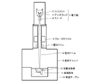
- the electron beam stacking method is performed by the following steps using the electron beam stacking apparatus shown in FIG. (1) One layer of metal powder having a constant thickness is spread. (2) A portion of the metal powder layer to be solidified is locally irradiated with an electron beam to heat the powder layer to instantaneously melt and solidify the powder. In this case, the electron beam is scanned based on the 3D data slice data. (3) The manufacturing table is lowered, and a metal powder layer is further spread.
- the electron beam stacking apparatus has the structure shown in FIG. 1, is composed of an electron gun 1, a focus coil 6, a deflection coil 7, and a vacuum chamber 9, and the inside of the apparatus is maintained in vacuum.
- the electron gun 1 includes a filament 2 that emits electrons, a grip cup 3 that pulls out the electrons, and an anode 4 that accelerates the electrons.
- electrons are extracted from the filament 2 heated to 2500° C. or more by the grip cup 3, accelerated through the anode 4 to half the speed of light, and radiated as an electron beam 8 on the metal powder 11 of one layer.
- the metal powder 11 is, for example, titanium powder having a particle size of 65 ⁇ m, and is housed in a manufacturing table arranged in the vacuum chamber 9.
- the electron beam 8 is focused on the metal powder 11 by the focus coil 6, and is scanned by the deflection coil 7 into a predetermined shape based on the 3D data/slice data.
- Metal laminating can also be performed by a laser laminating method using a laser laminating apparatus.
- the laser laminating method is to irradiate a metal powder with a laser laminating device, for example, a light emitting laser generated by a Yb laser device while controlling the irradiation position by a galvanometer mirror.
- the operation procedure is to irradiate the layered metal powder spread with a laser through a galvanometer mirror, melt and solidify only the irradiated part, and repeat this operation to stack to form a metal molded body with a predetermined shape. I will get it.
- Examples 1, 2, 4 A titanium alloy powder (Ti-6Al-4V) having a particle size (50% cumulative particle size and particle size range) shown in Table 1 below, which was manufactured by the rotating electrode method, was used, and a diameter of 10 mm and a height of 10 mm were obtained by an electron beam lamination method.
- a laminated molded body having a length of 100 mm was prepared, and a tensile test piece having a gauge length of 30 mm and a gauge diameter of 6 mm was cut out from the laminate.
- the manufacturing environment by the rotating electrode method was an argon atmosphere of 1.5 atm.
- a laminated compact having a diameter of 18 mm and a length of 160 mm was prepared by the electron beam lamination method, and a fatigue test piece having a gauge length of 15 mm and a gauge diameter of 6 mm was cut out from the laminated compact.
- Example 3 The titanium alloy powder (Ti-6Al-4V) having a particle size (50% cumulative particle size and particle size range) shown in Table 1 below, which was manufactured by the rotating electrode method, was used, and the laser method was used to perform Examples 1, 2 and A laminated molded body was prepared in the same manner as in 4, and tensile test pieces and fatigue test pieces were cut out from this laminated molded body in the same manner as in Examples 1, 2, and 4.
- Comparative Example 1 Using titanium alloy powder (Ti-6Al-4V) having a particle size (50% cumulative particle size and particle size range) shown in Table 1 below, which was produced by the gas atomization method, and electron beam lamination, Examples 1, 2 were used. A laminated molded body was prepared in the same manner as in No. 4, and tensile test pieces and fatigue test pieces were cut out from this laminated molded body in the same manner as in Examples 1, 2, and 4.
- Comparative example 2 Using titanium alloy powder (Ti-6Al-4V) having a particle size (50% cumulative particle size and particle size range) shown in Table 1 below, which was produced by the gas atomization method, and by electron beam lamination, Example 1, A laminated molded body was prepared in the same manner as 2 and 4, and the laminated molded body was subjected to HIP treatment. Tensile test pieces and fatigue test pieces were cut out from the HIP-treated laminated compact in the same manner as in Examples 1, 2, and 4.
- Comparative Example 3 The titanium alloy powder (Ti-6Al-4V) having a particle size (50% cumulative particle size and particle size range) shown in Table 1 below, which was manufactured by the rotating electrode method, was used, and the electron beam method was used to perform Examples 1 and 2 A laminated molded body was prepared in the same manner as in No. 4, and tensile test pieces and fatigue test pieces were cut out from this laminated molded body in the same manner as in Examples 1, 2, and 4.
- a raw material electrode rod is rotated in an inert atmosphere while being melted by a plasma arc and scattered to produce a spherical powder. Is the way.
- the composition of the titanium alloy powder (Ti-6Al-4V) produced by the rotating electrode method used in Examples 1 to 4 and Comparative Example 3 was 5.9 wt% Al, 4.1 wt% V, 0. Fe was 0.3% by weight, O was 0.10% by weight, N was 0.007% by weight, H was 0.007% by weight, and the balance was Ti.
- composition of the titanium alloy powder (Ti-6Al-4V) produced by the gas atomizing method used in Comparative Examples 1 and 2 was as follows: 6.1 wt% Al, 4.0 wt% V, 0.22 wt% % Fe, 0.075 wt% O, 0.004 wt% N, 0.004 wt% H, balance Ti.
- the electron beam stacking method performed in Examples 1, 2, and 4 and Comparative Examples 1 to 3 uses A2X manufactured by Arcam as an electron beam apparatus, a preheating temperature of 730° C., an output of 240 to 1260 W, and a scanning speed of 350 to 3800 mm.
- the stacking condition was /s.
- the laser laminating method carried out in Example 3 was carried out by using M2 manufactured by CONCEPT LASER Co., Ltd. as a laser device under the laminating conditions of no preheating, output of 400 W and scanning speed of 600 to 1300 mm/s.
- the HIP treatment of Comparative Example 2 was performed under the conditions of holding at 920° C. for 2 hours in an argon gas atmosphere of 100 MPa.
- the powder particle size distribution was measured by a laser diffractometer manufactured by Microtrac.
- the number of pores in the laminate was measured by observing the cross section of the laminate using a stereoscopic microscope (5-20 times). That is, the above-mentioned laminated molded body having a diameter of 18 mm and a length of 160 mm was cut at any three positions orthogonal to the length direction, and each cross section was observed while appropriately changing the magnification.
- the ratio of the powder containing pores in 1000 powders was determined by embedding the powder in a resin and observing with an optical microscope.
- a cylindrical frame is provided on the flat plate, the powder is dispersed in the cylindrical frame, and the resin is poured from above and solidified. Then, the resin in which the metal powder is embedded is polished, and its cross section is arbitrarily photographed with an optical microscope. From the obtained photograph or image data, the number of defective powders observed in 1,000 powders I asked.
- test piece (size: parallel portion 6 ⁇ 15 mm, total length 150 mm) was performed.
- the tensile test was carried out using Shimadzu Autograph AG-Xplus, and the tensile test piece cut out from the laminated round bar under the condition of strain rate of 1.5/(10000S) (size: parallel part width 2 mm x thickness 1 mm X length 10 mm).
- the fatigue strength at 10 7 times is as high as 550 MPa or more, and the tensile strength is high as 1000 MPa or more. ..
- the content of pores in the metal molded body is as low as 0.05/mm 2 or less because the titanium alloy powder used as the raw material was produced by the rotating electrode method. This is because the ratio of the powder containing P is as small as 0.1% or less.
- a laminate having a pore content of 0.05/mm 2 or less was obtained by any of the electron beam method (Examples 1, 2, 4) and the laser method (Example 3). There is.
- Comparative Example 1 the tensile strength is relatively high and 900 MPa, have high and 0.12 pieces / mm 2 pore content in the metallic shaped body, 10 7 times fatigue strength 400MPa and less.
- the high porosity content of 0.12 pieces/mm 2 in the metal compact is that the titanium alloy powder used is produced by the gas atomizing method, and the proportion of the powder containing pores is 0.18%. Because there are many.
- Comparative Example 3 was manufactured by the rotating electrode method, but the particle size was adjusted by classification in order to increase the powder particle size and clarify the effect. As a result, the ratio of the powder containing pores exceeded 0.1%, and as a result, the content of pores in the metal molded body increased to 0.12/mm 2 . To this end, 10 7 times fatigue strength did not reach to 500MPa.
- the titanium alloy powder used was produced by the gas atomizing method, and the proportion of the powder containing pores was as high as 0.18%, but the pore content in the metal compact was 0. It is as low as 02 pieces/mm 2, and therefore the fatigue strength after 10 7 cycles is as high as 600 MPa. This is because the metal molded body is subjected to HIP treatment. However, since the HIP treatment is applied, the tensile strength is 800 MPa, which is 100 MPa lower than that of Comparative Example 1 in which the HIP treatment is not applied.
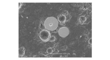
- FIG. 2 is a diagram showing pores in the gas atomized powder. From FIG. 2 it is observed that there are gas-containing pores in the powder.
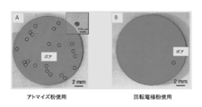
- FIG. 3 is a diagram showing pores of a laminated compact (A) using the titanium alloy powder obtained by the gas atomizing method and a laminated compact (B) using the titanium alloy powder obtained by the rotating electrode method. As shown in FIG. 3, in the laminated compact (A) using the titanium alloy powder obtained by the rotary electrode method, as an example, only one pore is observed. On the other hand, a large number of pores (22 in ⁇ 17.2 mm) are recognized in the laminated compact (B) using the titanium alloy powder obtained by the gas atomizing method. It is considered that the pores in this laminated body are the pores in the powder shown in FIG.
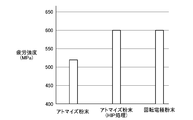
- FIG. 4 shows the fatigue strength (10 7 times) of the titanium alloy (Ti-6Al-4V). From Figure 4, rotating electrode powder molded laminate with (Examples 1-4, no HIP) is molded laminate using atomized powder (Comparative Example 1, HIP none) higher fatigue strength (10 7 times) the shows, it can be seen that shows the equivalent fatigue strength (10 7 times) and the laminate molded body using the atomized powder (Comparative example 2, there HIP).
Landscapes
- Engineering & Computer Science (AREA)
- Mechanical Engineering (AREA)
- Chemical & Material Sciences (AREA)
- Materials Engineering (AREA)
- Physics & Mathematics (AREA)
- Manufacturing & Machinery (AREA)
- Plasma & Fusion (AREA)
- Optics & Photonics (AREA)
- Metallurgy (AREA)
- Organic Chemistry (AREA)
- Powder Metallurgy (AREA)
- Manufacture Of Metal Powder And Suspensions Thereof (AREA)
Abstract
5.50~6.75重量%のAl、3.50 ~4.50重量%のV、0.20重量%以下のO、0.40重量%以下のFe、0.015重量%以下のH、0.08重量%以下のC、0.05重量%以下のN、及び不可避不純物を含むチタン合金積層成形体であって、ポア含有量が0.05個/mm2以下で、引張り強さが855MPa以上であることを特徴とするチタン合金積層成形体。
Description
本発明は、高い疲労強度を有するチタン合金積層成形体およびその製造方法に関するものである。特に、本発明は、金属積層法によって成形されたままの成形体であって、HIP処理を施すことなく疲労強度を有するチタン合金積層成形体およびその製造方法に関するものである。
チタン合金は、軽量でありながら高い引張強さを有することから、従来から航空機部品などに広く使用されている。この場合、チタン合金は、鋳造した後、圧延などの加工が施されるのが通常である。
一方、原料として金属粉末を用い、それを一層ずつ敷き詰め、レーザーあるいは電子ビームを照射して、特定の部位のみ加熱・溶解・凝固することで、型を用いることなく、最終形状の製品を作る製法として金属積層法が最近注目されている。
一方、原料として金属粉末を用い、それを一層ずつ敷き詰め、レーザーあるいは電子ビームを照射して、特定の部位のみ加熱・溶解・凝固することで、型を用いることなく、最終形状の製品を作る製法として金属積層法が最近注目されている。
チタン合金は、このような金属積層法に適した合金でもあり、金属積層法により得られた積層成形体は、圧延などすることなく、鋳造、圧延により得られた成形体と同等以上の高い引張強さを示す(非特許文献1参照)。
しかしながら、ガスアトマイズ法により得られた金属粉末(以下、ガスアトマイズ粉末と呼ぶ)を原料として用い、電子ビームを照射して金属積層体を成形した場合、処理を施さない積層のまま材(as built)について疲労試験をすると、金属積層体内部の欠陥の影響を受けて、多くの場合疲労強度が500MPa以下と低い。このような積層のまま材(as built)をHIP処理することで、疲労強度(107回)が改善され、600MPaまで向上することが報告されている(非特許文献2参照)。
しかしながら、ガスアトマイズ法により得られた金属粉末(以下、ガスアトマイズ粉末と呼ぶ)を原料として用い、電子ビームを照射して金属積層体を成形した場合、処理を施さない積層のまま材(as built)について疲労試験をすると、金属積層体内部の欠陥の影響を受けて、多くの場合疲労強度が500MPa以下と低い。このような積層のまま材(as built)をHIP処理することで、疲労強度(107回)が改善され、600MPaまで向上することが報告されている(非特許文献2参照)。
また、電子ビーム法及びレーザー法により積層成形された積層成形体の積層のまま材の疲労強度 (107回)は、それぞれ240MPa、300MPaと低いが、HIP処理することでいずれも580MPaまで向上することが報告されている(非特許文献3参照)。
更に、アルゴンガスを用いたガスアトマイズ法により得られた金属粉末においては、粉末粒子の粒径が大きいほどポア(空洞)体積率が高い粒子の割合が増加し、また、ポアの中にアルゴンガスが多く含まれることが知られている(非特許文献4、非特許文献5参照)。
更に、アルゴンガスを用いたガスアトマイズ法により得られた金属粉末においては、粉末粒子の粒径が大きいほどポア(空洞)体積率が高い粒子の割合が増加し、また、ポアの中にアルゴンガスが多く含まれることが知られている(非特許文献4、非特許文献5参照)。
更にまた、回転電極法により生成された金属粉末では、ガスアトマイズ粉末に比較してポア(空洞)を含む粒子は著しく少なくなること、ただし、粉末粒径が大きいほどポア(空洞)体積率が大きいことが知られている(例えば、非特許文献6参照)。
これらの現象は、粉末製造時に飛散した液滴は粒径が大きいほどその形が変形しやすく、そのために粉末製造時の環境に存在する不活性ガスを包み込む可能性が高いことによるものと考えられる。
これらの現象は、粉末製造時に飛散した液滴は粒径が大きいほどその形が変形しやすく、そのために粉末製造時の環境に存在する不活性ガスを包み込む可能性が高いことによるものと考えられる。
また、回転電極法(PREP法)を用いて製造された粒径271μmの金属粉末の焼結体をHIP処理して得たものが鍛造材よりも良好な疲労特性(耐久疲労限度比:疲労強度σ/引張強さσBが0.63)を示すことが報告されている(非特許文献7参照)。
上述した非特許文献に開示された原料粉末としてガスアトマイズ粉末を用いた電子ビームあるいはレーザーによる金属積層成形体は、一般的にはすぐれた特性を示す。
上述した非特許文献に開示された原料粉末としてガスアトマイズ粉末を用いた電子ビームあるいはレーザーによる金属積層成形体は、一般的にはすぐれた特性を示す。
例えば、非特許文献1に開示されたチタン合金の積層体は、従来製造法により得た圧延、鍛造材などに比較すれば、同等以上の高い引張特性及び高い伸びを示す。
また、非特許文献2及び非特許文献3に記載されたガスアトマイズ粉末を原料とした金属積層体の引張強さについて、積層のまま材とHIP処理材とを比較すると、引張強さ、耐力、及び伸びに関して大きな違いがある。即ち、HIP処理材は、積層のまま材に比較すると、伸びは向上しているが、引張強さ及び耐力が低い。また、HIP処理は、高温、高圧の下で行われるために、積層体の処理費用が高く、それによって製品コストが高くなるという問題がある。
また、非特許文献2及び非特許文献3に記載されたガスアトマイズ粉末を原料とした金属積層体の引張強さについて、積層のまま材とHIP処理材とを比較すると、引張強さ、耐力、及び伸びに関して大きな違いがある。即ち、HIP処理材は、積層のまま材に比較すると、伸びは向上しているが、引張強さ及び耐力が低い。また、HIP処理は、高温、高圧の下で行われるために、積層体の処理費用が高く、それによって製品コストが高くなるという問題がある。
更に、非特許文献7に記載された回転電極法により得た金属粉末の焼結体のHIP処理材は、鍛造材に比較しても高い疲労強度を示すことが報告されているが、HIP処理しない限り粉末そのものが焼結しないために高い疲労強度を得ることはできない。しかも、HIP処理は高温、高圧をかけるために処理費用がかかり、製品コストが高くなるという問題がある。
安達充ほか:軽金属,66(2016),360-367
Xiaoli Shui etc:Materials Science &Engineering A 680(2017),239-248
唐土庄太郎ほか:粉体および粉末冶金, 61(2014),250-254
R.Gering etc :Materials Science &Engineering A 252(1998),239-247
G.Chen etc :Powder Technology 330(2018)425-430
G,Chen etc: Powder Technology 333(2018)38-46
磯西和夫、時実正治:鉄と鋼,(1990),2108-2115
本発明は、以上のような背景からなされたものである。即ち、金属積層成形体は急冷凝固組織であるため、従来法では得られない微細組織を示すことから、引張強さは高い値を示す。しかし、ガスアトマイズ粉末を積層した場合、金属積層体中にポアがわずかではあるが存在するため、わずかな欠陥でも影響をうけやすい疲労特性が低い。上述したように、このような疲労特性を改善するため、HIP処理が行われることが報告されている。しかし、HIP処理はコストがかかるため、HIP処理を行わずに優れた疲労特性を得ることが望まれる。
以上のことから、本発明の目的は、引張強さが高いという積層成形体の特徴を最大限に生かしつつ、かつHIP処理を行うことなく疲労強度が優れたチタン合金積層成形体及びその製造方法を提供することにある。
より具体的には、本発明の目的は、ガスアトマイズ粉末を原料とする積層成形体の成形されたまま(as built)と同等以上の引張り強さを有するとともに、ガスアトマイズ粉末を原料とする積層成形体の成形されたまま(as built)よりも高く、HIP処理材の80%以上の疲労強度を示すチタン合金(Ti-6Al-4V)積層成形体及びその製造方法を提供することにある。
より具体的には、本発明の目的は、ガスアトマイズ粉末を原料とする積層成形体の成形されたまま(as built)と同等以上の引張り強さを有するとともに、ガスアトマイズ粉末を原料とする積層成形体の成形されたまま(as built)よりも高く、HIP処理材の80%以上の疲労強度を示すチタン合金(Ti-6Al-4V)積層成形体及びその製造方法を提供することにある。
なお、ガスアトマイズ粉末を原料とする積層成形体の成形されたまま(as built)と同等以上の引張り強さとは、チタン合金(Ti-6Al-4V)積層成形体の引張強さの代表値900MPaの95%以上であることを意味する。
以上の課題を解決するため、本発明の第1の態様は、5.50~6.75重量%のAl、3.50 ~4.50重量%のV、0.20重量%以下のO、0.40重量%以下のFe、0.015重量%以下のH、0.08重量%以下のC、0.05重量%以下のN、及び不可避不純物を含むチタン合金積層成形体であって、ポア含有量が0.05個/mm2以下で、引張り強さが855MPa以上であることを特徴とするチタン合金積層成形体を提供する。
上記本発明の第1の態様に係るチタン合金積層成形体において、引張強さがガスアトマイズ粉末を原料とする積層体の成形されたまま(as built)と同等以上であり、疲労強度がガスアトマイズ粉を原料とする積層体のHIP処理材の疲労強度の80%以上とすることができる。
また、107回の疲労強度を500MPa以上とすることができる。
また、107回の疲労強度を500MPa以上とすることができる。
本発明の第2の態様は、5.50~6.75重量%のAl、3.50 ~4.50重量%のV、0.20重量%以下のO、0.40重量%以下のFe、0.015重量%以下のH、0.08重量%以下のC、0.05重量%以下のN、及び不可避不純物を含み、ポアを含む粉末粒子の割合が0.1%以下のチタン合金粉末を金属積層法により積層成形することを特徴とするチタン合金積層成形体の製造方法を提供する。
上記本発明の第2の態様に係るチタン合金積層成形体の製造方法において、前記チタン合金粉末の粒径を30~250μmとすることができる。
また、合金粉末を、回転電極法を用いて製造されたものとすることができる。
上記本発明の第2の態様に係るチタン合金積層成形体の製造方法において、前記チタン合金粉末の粒径を30~250μmとすることができる。
また、合金粉末を、回転電極法を用いて製造されたものとすることができる。
本発明によれば、引張強さが高いという積層成形体の特徴を最大限に生かしつつ、かつHIP処理を行うことなく疲労強度が優れたチタン合金積層成形体及びその製造方法が提供される。
特に、本発明によれば、ガスアトマイズ粉末を原料とする積層成形体の成形されたまま材(as built)と同等以上の引張り強さを有するとともに、ガスアトマイズ粉末を原料とする積層成形体の成形されたまま材(as built)よりも高く、HIP処理材と遜色の無い疲労強度を示すチタン合金積層成形体及びその製造方法が提供される。
特に、本発明によれば、ガスアトマイズ粉末を原料とする積層成形体の成形されたまま材(as built)と同等以上の引張り強さを有するとともに、ガスアトマイズ粉末を原料とする積層成形体の成形されたまま材(as built)よりも高く、HIP処理材と遜色の無い疲労強度を示すチタン合金積層成形体及びその製造方法が提供される。
以下、本発明の実施形態について、詳細に説明する。
上述したように、金属積層成形体は急冷凝固組織であり、従来法では得られない微細組織を示すことから、高い引張強さを示す一方、金属積層体中にポアが存在する場合には、疲労特性が低い。
ここで、積層体中のポアの発生時期は、以下の二つが考えられる。
一つのポアの発生時期は積層時であり、a)積層条件が適正でないために発生する未溶融粉末に起因するポアが考えられる。この場合、単に1個の粒子の未溶融にとどまらず複雑、粗大なポアとなる。また、b)装置内環境中に不活性ガスを使用することをメインとするレーザー法の場合の巻き込みガスによるポアの可能性もある。a)のポアは、積層時の成形条件を適正にすることで解決することができる。b)のポアは、真空雰囲気で行われるためガス巻き込みが防止される電子ビーム法を採用することにより解決することができる。
上述したように、金属積層成形体は急冷凝固組織であり、従来法では得られない微細組織を示すことから、高い引張強さを示す一方、金属積層体中にポアが存在する場合には、疲労特性が低い。
ここで、積層体中のポアの発生時期は、以下の二つが考えられる。
一つのポアの発生時期は積層時であり、a)積層条件が適正でないために発生する未溶融粉末に起因するポアが考えられる。この場合、単に1個の粒子の未溶融にとどまらず複雑、粗大なポアとなる。また、b)装置内環境中に不活性ガスを使用することをメインとするレーザー法の場合の巻き込みガスによるポアの可能性もある。a)のポアは、積層時の成形条件を適正にすることで解決することができる。b)のポアは、真空雰囲気で行われるためガス巻き込みが防止される電子ビーム法を採用することにより解決することができる。
もう一つのポアの発生時期は積層成形する前であり、ガスアトマイズ法により得られた原料粉末の中にすでにポアが存在している。原料粉末の製造時の段階で飛散した液滴に包まれたガスが粉末内に巻き込まれ、一旦巻き込まれれば、積層成形の条件の有無に関係なく積層成形体中に入り込むのである。これを防止するには、ガスアトマイズ法によらず、回転電極法により得た金属粉末を用いればよい。
なお、回転電極法とは、材料金属をプラズマにより融解して、液滴として電極表面から遠心力により吹き飛ばし、金属粉末を得る方法である。
以上のことから、積層体中のポアは、積層条件を適正にすること、電子ビーム法により積層すること、及び回転電極法により得た原料粉末を用いること、のいずれか又はその組み合わせにより、低減することが出来る。
以上のことから、積層体中のポアは、積層条件を適正にすること、電子ビーム法により積層すること、及び回転電極法により得た原料粉末を用いること、のいずれか又はその組み合わせにより、低減することが出来る。
本発明の一実施形態に係るチタン合金積層成形体は、チタン合金粉末を積層することにより得られたものである。積層方法としては、粉末床溶融結合法を用いることが出来る。粉末床溶融結合法は、原料金属粉末を一層ずつ敷き詰め、これにレーザーや電子ビームなどを照射して、特定の部位のみを溶解・固化して積層する方法である。
得られた積層成形体は、5.50~6.75重量%のAl、3.50 ~4.50重量%のV、0.20重量%以下のO、0.40重量%以下のFe、0.015重量%以下のH、0.08重量%以下のC、0.05重量%以下のN、及び不可避不純物を含む組成を有する。
得られた積層成形体は、5.50~6.75重量%のAl、3.50 ~4.50重量%のV、0.20重量%以下のO、0.40重量%以下のFe、0.015重量%以下のH、0.08重量%以下のC、0.05重量%以下のN、及び不可避不純物を含む組成を有する。
このチタン合金積層成形体は、ポア含有量が0.05個/mm2以下、好ましくは0.03個/mm2以下である。ポア含有量は金属積層後の疲労強度に大きな影響を持つ因子である。0.05個/mm2を超えるポアが積層成形体中に存在すると、破壊の起点が多くなり、疲労破壊が進みやすくなる。このため、疲労強度を高くするために、積層成形体のポア含有量は0.05個/mm2以下である必要がある。
このように、上記合金組成を有し、ポア含有量が0.05個/mm2以下であるチタン合金積層成形体は、引張強さがガスアトマイズ粉を原料とする積層体の成形されたまま材(as built)と同等以上であり、また、その疲労強度はガスアトマイズ粉を原料とする積層体のHIP処理材のそれの80%以上である。
また、上記合金組成を有し、ポア含有量が0.05個/mm2以下であるチタン合金積層成形体は、107回の疲労強度が500MPa以上である。
また、上記合金組成を有し、ポア含有量が0.05個/mm2以下であるチタン合金積層成形体は、107回の疲労強度が500MPa以上である。
本発明の第2の実施形態に係るチタン合金積層成形体の製造方法は、チタン合金粉末を金属積層法により積層成形することからなる。原料として用いるチタン合金粉末は、5.50~6.75重量%のAl、3.50 ~4.50重量%のV、0.20重量%以下のO、0.40重量%以下のFe、0.015重量%以下のH、0.08重量%以下のC、0.05重量%以下のN、及び不可避不純物を含む組成を有する。
また、チタン合金粉末におけるポアを含む粉末の割合は0.1%以下、好ましくは0.05%以下である。
チタン合金粉末中のポアの割合は金属積層後の疲労強度に大きな影響を持つ因子である。チタン合金粉末のポアは、チタン合金粉末を積層してなる積層成形体中においてもそのまま存在することになる。従って、チタン合金粉末中のポアの体積含有率が0.1を超えると、積層成形体中のポアが疲労破壊の起点となる。このため、高い疲労強度の積層成形体を得るためには、チタン合金粉末中のポアを含む粉末の割合が0.1%以下である必要がある。
チタン合金粉末中のポアの割合は金属積層後の疲労強度に大きな影響を持つ因子である。チタン合金粉末のポアは、チタン合金粉末を積層してなる積層成形体中においてもそのまま存在することになる。従って、チタン合金粉末中のポアの体積含有率が0.1を超えると、積層成形体中のポアが疲労破壊の起点となる。このため、高い疲労強度の積層成形体を得るためには、チタン合金粉末中のポアを含む粉末の割合が0.1%以下である必要がある。
上述したように、チタン合金粉末の粒径は、積層成形体中のポアの存在に影響を与える。チタン合金粉末の粒径は、30~250μmであることが好ましく、より好ましくは40~150μmである。合金粉末粒子の粒径が30μm未満では、電子ビーム積層装置の場合、装置中の雰囲気が真空であるため、チタン合金粉末が装置内に吸引されて、装置の真空系の故障の原因となる。また、粉末の流動性も低下するため、チタン合金粉末の粒径は30μm以上であることが好ましく、より好ましくは40μm以上である。
一方、粉末製造時に粉末が大きいほど粉末に巻き込まれるポアが多くなる。このため、250μm以下であることが好ましく、より好ましくは150μm以下である。また、チタン合金粉末粒子の粒径が大きいほど、積層成形体の表面粗度が粗くなり、積層成形体のまま使用する製品においては、その粗さが引張強さ、疲労強さの値を低下させるので、その意味でもチタン合金粉末粒子の粒径は250μm以下が好ましく、より好ましくは150μm以下である。
チタン合金粉末は、回転電極法により製造されることが好ましい。回転電極法により製造されたチタン合金粉末は、粉末粒子内のポアの少なさ、粒径、真球度、サテライト球の発生の少なさ、酸化物の少なさの観点から、積層成形法に用いるのに適したものであり、このチタン合金粉末を用いて得られた積層成形体は、HIP処理なしで高い疲労強度を示す。なお、回転電極法による粉末製造時の装置内環境は、不活性ガス雰囲気であるが、装置内環境への空気の侵入を防ぐために、たとえば1-2気圧程度に保持することが好ましい。
なお、回転電極法以外の方法であっても、積層体中のポアが少ないものであれば本発明と同様の疲労特性を示す可能性はある。たとえば、高速回転する円盤状のディスクに液滴を落下させディスクの縁で球状粉末を生成する「遠心力回転円盤法」や、低速回転する棒状原料をその外側に配置された誘導コイルにより溶融させた液体にアルゴンガスを衝突させて粉末にする「電磁誘導加熱式ガスアトマイズ法」なども適用の可能性はある。
以上説明したチタン合金粉末は、金属積層法により成形されるが、金属積層法としては、電子ビーム積層方法とレーザー積層方法がある。
一般に、電子ビーム積層方法は、図1に示す電子ビーム積層装置を用いて、以下の工程により行われる。
(1)一定厚みの金属粉末層を一層敷きつめる。
(2)金属粉末層の固化予定箇所に局部的に電子ビームを照射して粉末層を加熱し、粉末を瞬間溶融するとともに瞬間固化する。この場合、電子ビームは、3Dデータ・スライスデータに基づき走査される。
(3)製造テーブルを降下させ、更に金属粉末層を敷きつめる。
(4)以上の工程を繰返し、金属を順次積層し、最終形状の積層成形体を得た後、未固化の粉末を取り除いて、積層成形体を得る。
チタン合金粉末を以上の工程に供することにより、所定の形状のチタン合金積層成形体を得ることができる。
一般に、電子ビーム積層方法は、図1に示す電子ビーム積層装置を用いて、以下の工程により行われる。
(1)一定厚みの金属粉末層を一層敷きつめる。
(2)金属粉末層の固化予定箇所に局部的に電子ビームを照射して粉末層を加熱し、粉末を瞬間溶融するとともに瞬間固化する。この場合、電子ビームは、3Dデータ・スライスデータに基づき走査される。
(3)製造テーブルを降下させ、更に金属粉末層を敷きつめる。
(4)以上の工程を繰返し、金属を順次積層し、最終形状の積層成形体を得た後、未固化の粉末を取り除いて、積層成形体を得る。
チタン合金粉末を以上の工程に供することにより、所定の形状のチタン合金積層成形体を得ることができる。
電子ビーム積層装置は、図1に示す構造を有し、電子銃1、フォーカスコイル6、偏向コイル7、及び真空チャンバ9により構成され、装置内は真空に維持されている。電子銃1は、電子を放出するフィラメント2、電子を引き出すグリップカップ3、及び電子を加速するアノード4を備えている。
電子銃1において、2500℃以上に加熱されたフィラメント2から電子がグリップカップ3により引き出され、アノード4を通して光速の半分のスピードに加速され、電子ビーム8として一層の金属粉末11に照射される。金属粉末11は、例えば粒径65μmのチタン粉末であり、真空チャンバ9内に配置された製造テーブルに収容されている。この際、電子ビーム8はフォーカスコイル6により金属粉末11に焦点が合わされ、偏向コイル7により3Dデータ・スライスデータに基づき所定の形状に走査される。
電子銃1において、2500℃以上に加熱されたフィラメント2から電子がグリップカップ3により引き出され、アノード4を通して光速の半分のスピードに加速され、電子ビーム8として一層の金属粉末11に照射される。金属粉末11は、例えば粒径65μmのチタン粉末であり、真空チャンバ9内に配置された製造テーブルに収容されている。この際、電子ビーム8はフォーカスコイル6により金属粉末11に焦点が合わされ、偏向コイル7により3Dデータ・スライスデータに基づき所定の形状に走査される。
電子ビーム8が層状の金属粉末11に照射されると、その運動エネルギーが熱に変換され、その熱によって金属粉末が加熱され、溶融され、その後急速凝固される。その上に更に層状の金属粉末11が敷きつめられ、同様の工程が繰り返されることにより、金属が積層され、所定の形状の最終製品が成形される。
金属積層は、レーザー積層装置を用いたレーザー積層方法によっても行うことが出来る。レーザー積層方法は、レーザー積層装置、例えばYbレーザー装置により生成された発光レーザーをガルバノメーターミラーにより照射位置を制御して金属粉末に照射するものである。その操作手順は、敷きつめた層状の金属粉末に、ガルバノメーターミラーを通してレーザーを照射し、照射部分のみを溶融し、固化し、この操作を繰り返して積層することにより、所定の形状の金属成形体を得るものである。
金属積層は、レーザー積層装置を用いたレーザー積層方法によっても行うことが出来る。レーザー積層方法は、レーザー積層装置、例えばYbレーザー装置により生成された発光レーザーをガルバノメーターミラーにより照射位置を制御して金属粉末に照射するものである。その操作手順は、敷きつめた層状の金属粉末に、ガルバノメーターミラーを通してレーザーを照射し、照射部分のみを溶融し、固化し、この操作を繰り返して積層することにより、所定の形状の金属成形体を得るものである。
以下、本発明の実施例を比較例と対比して説明する。
実施例1、2、4
回転電極法により製造された、下記表1に示す粒径(50%累積粒径及び粒径範囲)のチタン合金粉末(Ti-6Al-4V)を用い、電子ビーム積層法により、直径10mm、高さ100mmの積層成形体を作成し、この積層成形体から標点間距離30mm、標点直径6mmの引張試験片を切り出した。
なお、回転電極法による製造環境は1.5気圧のアルゴン雰囲気とした。
同様に、電子ビーム積層法により、直径18mm、長さ160mmの積層成形体を作成し、この積層成形体から標点間距離15mm、標点直径6mmの疲労試験片を切り出した。
実施例1、2、4
回転電極法により製造された、下記表1に示す粒径(50%累積粒径及び粒径範囲)のチタン合金粉末(Ti-6Al-4V)を用い、電子ビーム積層法により、直径10mm、高さ100mmの積層成形体を作成し、この積層成形体から標点間距離30mm、標点直径6mmの引張試験片を切り出した。
なお、回転電極法による製造環境は1.5気圧のアルゴン雰囲気とした。
同様に、電子ビーム積層法により、直径18mm、長さ160mmの積層成形体を作成し、この積層成形体から標点間距離15mm、標点直径6mmの疲労試験片を切り出した。
実施例3
回転電極法により製造された、下記表1に示す粒径(50%累積粒径及び粒径範囲)のチタン合金粉末(Ti-6Al-4V)を用い、レーザー法により、実施例1、2、4と同様にして積層成形体を作成し、この積層成形体から、実施例1、2、4と同様にして引張試験片及び疲労試験片を切り出した。
回転電極法により製造された、下記表1に示す粒径(50%累積粒径及び粒径範囲)のチタン合金粉末(Ti-6Al-4V)を用い、レーザー法により、実施例1、2、4と同様にして積層成形体を作成し、この積層成形体から、実施例1、2、4と同様にして引張試験片及び疲労試験片を切り出した。
比較例1
ガスアトマイズ法により製造された、下記表1に示す粒径(50%累積粒径及び粒径範囲)のチタン合金粉末(Ti-6Al-4V)を用い、電子ビーム積層法により、実施例1、2、4と同様にして積層成形体を作成し、この積層成形体から、実施例1、2、4と同様にして引張試験片及び疲労試験片を切り出した。
ガスアトマイズ法により製造された、下記表1に示す粒径(50%累積粒径及び粒径範囲)のチタン合金粉末(Ti-6Al-4V)を用い、電子ビーム積層法により、実施例1、2、4と同様にして積層成形体を作成し、この積層成形体から、実施例1、2、4と同様にして引張試験片及び疲労試験片を切り出した。
比較例2
ガスアトマイズ法により製造された、下記表1に示す粒径(50%累積粒径及び粒径範囲)のチタン合金粉末(Ti-6Al-4V)を用い、電子ビーム積層法によりにより、実施例1、2、4と同様にして積層成形体を作成し、この積層成形体をHIP処理した。HIP処理された積層成形体から、実施例1、2、4と同様にして引張試験片及び疲労試験片を切り出した。
ガスアトマイズ法により製造された、下記表1に示す粒径(50%累積粒径及び粒径範囲)のチタン合金粉末(Ti-6Al-4V)を用い、電子ビーム積層法によりにより、実施例1、2、4と同様にして積層成形体を作成し、この積層成形体をHIP処理した。HIP処理された積層成形体から、実施例1、2、4と同様にして引張試験片及び疲労試験片を切り出した。
比較例3
回転電極法により製造された、下記表1に示す粒径(50%累積粒径及び粒径範囲)のチタン合金粉末(Ti-6Al-4V)を用い、電子ビーム法により、実施例1、2、4と同様にして積層成形体を作成し、この積層成形体から、実施例1、2、4と同様にして引張試験片及び疲労試験片を切り出した。
回転電極法により製造された、下記表1に示す粒径(50%累積粒径及び粒径範囲)のチタン合金粉末(Ti-6Al-4V)を用い、電子ビーム法により、実施例1、2、4と同様にして積層成形体を作成し、この積層成形体から、実施例1、2、4と同様にして引張試験片及び疲労試験片を切り出した。
以上の実施例1-4及び比較例1-3の引張試験片及び疲労試験片について、引張試験及び疲労試験を行い、下記表1に示す結果を得た。
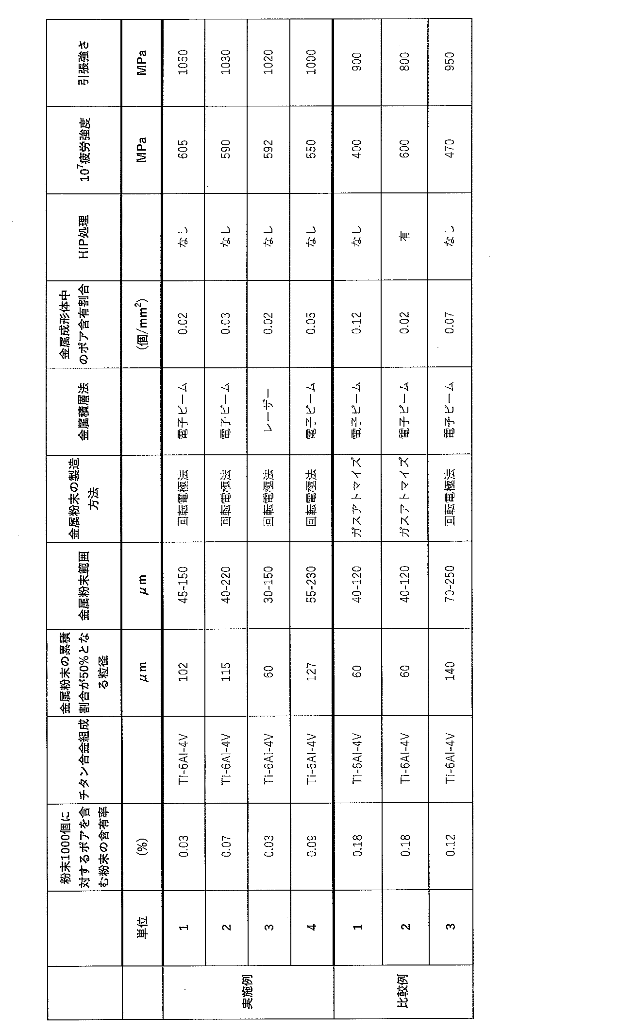
なお、実施例1~4及び比較例3で使用した粉末を生成する回転電極法は、不活性雰囲気で原料となる電極棒を回転させつつプラズマアークにて溶かし、飛散させて球形粉末を作成する方法である。
実施例1~4及び比較例3で使用した回転電極法により製造されたチタン合金粉末(Ti-6Al-4V)の組成は、5.9重量%のAl、4.1重量%のV、0.3重量%のFe、0.10重量%のO、0.007重量%のN、0.007重量%のH、残部Tiであった。
また、比較例1及び2で使用したガスアトマイズ法により製造されたチタン合金粉末(Ti-6Al-4V)の組成は、6.1重量%のAl、4.0重量%のV、0.22重量%のFe、0.075重量%のO、0.004重量%のN、0.004重量%のH、残部Tiであった。
実施例1~4及び比較例3で使用した回転電極法により製造されたチタン合金粉末(Ti-6Al-4V)の組成は、5.9重量%のAl、4.1重量%のV、0.3重量%のFe、0.10重量%のO、0.007重量%のN、0.007重量%のH、残部Tiであった。
また、比較例1及び2で使用したガスアトマイズ法により製造されたチタン合金粉末(Ti-6Al-4V)の組成は、6.1重量%のAl、4.0重量%のV、0.22重量%のFe、0.075重量%のO、0.004重量%のN、0.004重量%のH、残部Tiであった。
実施例1、2、4及び比較例1~3で行った電子ビーム積層法は、電子ビーム装置として、Arcam社製 A2Xを使用し、予熱温度730℃、出力240~1260W、スキャン速度350~3800mm/sの積層条件で行った。
実施例3で行ったレーザー積層法は、レーザー装置として、CONCEPT LASER社製 M2を使用し、予熱無し、出力400W、スキャン速度600~1300mm/sの積層条件で行った。
比較例2のHIP処理は、100MPaのアルゴンガス雰囲気で920℃×2時間保持の条件で行った。
実施例3で行ったレーザー積層法は、レーザー装置として、CONCEPT LASER社製 M2を使用し、予熱無し、出力400W、スキャン速度600~1300mm/sの積層条件で行った。
比較例2のHIP処理は、100MPaのアルゴンガス雰囲気で920℃×2時間保持の条件で行った。
粉末粒度分布測定は、マイクロトラック社のレーザー回折装置により行った。
積層体中のポアの数の測定は、実体顕微鏡(5-20倍)を用いて積層体断面を観察することにより行った。すなわち、上述した直径18mm、長さ160mmの積層成形体を、長さ方向と直交する任意の3つの位置で切断し、それぞれの断面を、倍率を適宜変えて観察した。観察面積は、半径9mm×半径9mm×3.14×3面=763mm2とした。
粉末1000個中のポア含む粉末の割合は、粉末を樹脂に埋め込み、光学顕微鏡にて観察することにより行った。すなわち、平板に筒状枠を設け、筒状枠の中に粉末を散布して、その上から樹脂を流し込み固める。そして、金属粉末が埋め込まれた樹脂を研磨し、その断面を任意に光学顕微鏡にて撮影し、得られた写真又は画像データから1000個相当の粉末の中で観察される欠陥のある粉末の数を求めた。
積層体中のポアの数の測定は、実体顕微鏡(5-20倍)を用いて積層体断面を観察することにより行った。すなわち、上述した直径18mm、長さ160mmの積層成形体を、長さ方向と直交する任意の3つの位置で切断し、それぞれの断面を、倍率を適宜変えて観察した。観察面積は、半径9mm×半径9mm×3.14×3面=763mm2とした。
粉末1000個中のポア含む粉末の割合は、粉末を樹脂に埋め込み、光学顕微鏡にて観察することにより行った。すなわち、平板に筒状枠を設け、筒状枠の中に粉末を散布して、その上から樹脂を流し込み固める。そして、金属粉末が埋め込まれた樹脂を研磨し、その断面を任意に光学顕微鏡にて撮影し、得られた写真又は画像データから1000個相当の粉末の中で観察される欠陥のある粉末の数を求めた。
疲労強度の試験は、油圧サーボ式疲労試験機(モデル8801)を使用し、試験時周波数が10Hz、応力比Rが0.1の一軸(引張/引張)条件で、積層丸棒から切り出した疲労試験片(サイズ: 平行部が6φ×15mm、全長150mm)に対して実施した。
引張試験は、島津製作所製 オートグラフAG-Xplusを使用し、歪み速度が1.5/(10000S)の条件で、積層丸棒から切り出した引張試験片(サイズ:平行部が幅2mm×厚み1mm×長さ10mm)に対して実施した。
上記表1に示す結果から、以下のことが明らかである。
実施例1-4では、金属成形体中のポア含有量が0.05個/mm2以下であるため、107回疲労強度がいずれも550MPa以上と高く、また引張強さが1000MPa以上と高い。
実施例1-4において、金属成形体中のポア含有量が0.05個/mm2以下と低いのは、原料として用いたチタン合金粉末が、回転電極法により製造されたものであり、ポアを含む粉末の割合が0.1%以下と少ないためである。この場合、電子ビーム法(実施例1、2、4)、レーザー法(実施例3)のいずれの積層法によっても、ポア含有量が0.05個/mm2以下の積層体が得られている。
実施例1-4では、金属成形体中のポア含有量が0.05個/mm2以下であるため、107回疲労強度がいずれも550MPa以上と高く、また引張強さが1000MPa以上と高い。
実施例1-4において、金属成形体中のポア含有量が0.05個/mm2以下と低いのは、原料として用いたチタン合金粉末が、回転電極法により製造されたものであり、ポアを含む粉末の割合が0.1%以下と少ないためである。この場合、電子ビーム法(実施例1、2、4)、レーザー法(実施例3)のいずれの積層法によっても、ポア含有量が0.05個/mm2以下の積層体が得られている。
これに対し、比較例1では、引張強さが900MPaと比較的高いが、金属成形体中のポア含有量が0.12個/mm2と高いため、107回疲労強度が400MPaと低い。金属成形体中のポア含有量が0.12個/mm2と高いのは、用いたチタン合金粉末が、ガスアトマイズ法により製造されたものであり、ポアを含む粉末の割合が0.18%と多いためである。
比較例3は、比較例1、2と異なり、回転電極法により製造されたものであるが、粉末粒径大きくしてその影響を明らかにするために分級により粒径調整を行った。その結果、ポアを含む粉末の割合が0.1%を超えることになり、その結果、金属成形体中のポア含有量が0.12個/mm2と高くなった。このために、107回疲労強度が500MPaに達しなかった。
なお、比較例2では、用いたチタン合金粉末が、ガスアトマイズ法により製造されたものであり、ポアを含む粉末の割合が0.18%と多いが、金属成形体中のポア含有量が0.02個/mm2と低く、そのため107回疲労強度が600MPaと高い。これは、金属成形体にHIP処理を施しているためである。ただし、HIP処理を施しているため、引張強さは800MPaであり、HIP処理を施さない比較例1よりも100MPa低下している。
図2は、ガスアトマイズ粉末中のポアを示す図である。図2から粉末の中にガスを含むポアが存在することが観察される。
図3は、ガスアトマイズ法により得たチタン合金粉末を用いた積層成形体(A)と回転電極法により得たチタン合金粉末を用いた積層成形体(B)のポアを示す図である。図3に示すように、回転電極法により得たチタン合金粉末を用いた積層成形体(A)には、一例ではあるが、1個しかポアは観察されない。これに対し、ガスアトマイズ法により得たチタン合金粉末を用いた積層成形体(B)には多数のポア(Φ17.2mm中に22個)が認められる。この積層体中のポアは、図2に示す粉末中のポアが巻き込まれたものと考えられる。
図3は、ガスアトマイズ法により得たチタン合金粉末を用いた積層成形体(A)と回転電極法により得たチタン合金粉末を用いた積層成形体(B)のポアを示す図である。図3に示すように、回転電極法により得たチタン合金粉末を用いた積層成形体(A)には、一例ではあるが、1個しかポアは観察されない。これに対し、ガスアトマイズ法により得たチタン合金粉末を用いた積層成形体(B)には多数のポア(Φ17.2mm中に22個)が認められる。この積層体中のポアは、図2に示す粉末中のポアが巻き込まれたものと考えられる。
図4にチタン合金(Ti-6Al-4V)の疲労強度(107回)を示す。図4から、回転電極粉末を用いた積層成形体(実施例1-4、HIPなし)が、アトマイズ粉末を用いた積層成形体(比較例1、HIPなし)より高い疲労強度(107回)を示しており、アトマイズ粉末を用いた積層成形体(比較例2、HIPあり)と同等の疲労強度(107回)を示していることがわかる。
Claims (5)
- 5.50~6.75重量%のAl、3.50 ~4.50重量%のV、0.20重量%以下のO、0.40重量%以下のFe、0.015重量%以下のH、0.08重量%以下のC、0.05重量%以下のN、及び不可避不純物を含むチタン合金積層成形体であって、ポア含有量が0.05個/mm2以下で、引張り強さが855MPa以上であることを特徴とするチタン合金積層成形体。
- 107回の疲労強度が500MPa以上であることを特徴とする請求項1に記載のチタン合金積層成形体。
- 5.50~6.75重量%のAl、3.50 ~4.50重量%のV、0.20重量%以下のO、0.40重量%以下のFe、0.015重量%以下のH、0.08重量%以下のC、0.05重量%以下のN、及び不可避不純物を含み、ポアを含む粉末の割合が0.1%以下のチタン合金粉末を金属積層法により積層成形することを特徴とするチタン合金積層成形体の製造方法。
- 前記チタン合金粉末の粒径が30~250μmであることを特徴とする請求項3に記載のチタン合金積層成形体の製造方法。
- 前記チタン合金粉末が回転電極法を用いて製造されたことを特徴とする請求項3又は4に記載のチタン合金積層成形体の製造方法。
Priority Applications (4)
| Application Number | Priority Date | Filing Date | Title |
|---|---|---|---|
| JP2020543132A JP6785491B1 (ja) | 2019-02-01 | 2020-01-31 | チタン合金積層成形体およびその製造方法 |
| EP20749460.0A EP3919206A4 (en) | 2019-02-01 | 2020-01-31 | TITANIUM ALLOY LAYERING COMPACT AND METHOD FOR ITS MANUFACTURE |
| US17/427,840 US12152289B2 (en) | 2019-02-01 | 2020-01-31 | Titanium alloy additive manufacturing product and method of manufacturing the same |
| US18/927,096 US20260110059A1 (en) | 2019-02-01 | 2024-10-25 | Titanium alloy additive manufacturing product and method of manufacturing the same |
Applications Claiming Priority (2)
| Application Number | Priority Date | Filing Date | Title |
|---|---|---|---|
| JP2019-017260 | 2019-02-01 | ||
| JP2019017260 | 2019-02-01 |
Related Child Applications (2)
| Application Number | Title | Priority Date | Filing Date |
|---|---|---|---|
| US17/427,840 A-371-Of-International US12152289B2 (en) | 2019-02-01 | 2020-01-31 | Titanium alloy additive manufacturing product and method of manufacturing the same |
| US18/927,096 Division US20260110059A1 (en) | 2019-02-01 | 2024-10-25 | Titanium alloy additive manufacturing product and method of manufacturing the same |
Publications (1)
| Publication Number | Publication Date |
|---|---|
| WO2020158945A1 true WO2020158945A1 (ja) | 2020-08-06 |
Family
ID=71842110
Family Applications (1)
| Application Number | Title | Priority Date | Filing Date |
|---|---|---|---|
| PCT/JP2020/003792 Ceased WO2020158945A1 (ja) | 2019-02-01 | 2020-01-31 | チタン合金積層成形体およびその製造方法 |
Country Status (4)
| Country | Link |
|---|---|
| US (2) | US12152289B2 (ja) |
| EP (1) | EP3919206A4 (ja) |
| JP (1) | JP6785491B1 (ja) |
| WO (1) | WO2020158945A1 (ja) |
Cited By (2)
| Publication number | Priority date | Publication date | Assignee | Title |
|---|---|---|---|---|
| WO2022024582A1 (ja) * | 2020-07-30 | 2022-02-03 | 日本積層造形株式会社 | チタン合金積層成形体並びにその製造方法及び原料 |
| CN119035778A (zh) * | 2024-11-04 | 2024-11-29 | 烟台大学 | 一种大尺寸钛合金增材制造装置及方法 |
Families Citing this family (2)
| Publication number | Priority date | Publication date | Assignee | Title |
|---|---|---|---|---|
| TW202403063A (zh) | 2021-05-19 | 2024-01-16 | 美商卡斯登製造公司 | β強化鈦合金及其製造方法 |
| CN116121589B (zh) * | 2022-12-02 | 2024-06-18 | 大连理工大学 | 一种增材制造用高温超高强钛合金、制备方法及其应用 |
Citations (4)
| Publication number | Priority date | Publication date | Assignee | Title |
|---|---|---|---|---|
| JPH10251778A (ja) * | 1997-03-11 | 1998-09-22 | Japan Atom Energy Res Inst | 強度・靭性に富む金属間化合物及びその製造方法 |
| JP2016053198A (ja) * | 2014-09-04 | 2016-04-14 | 株式会社コイワイ | 金属成形体および金属成形体用金属粉末 |
| JP2017048410A (ja) * | 2015-08-31 | 2017-03-09 | 高周波熱錬株式会社 | α+β型チタン合金の熱処理方法、及びその方法を用いて製造されたα+β型チタン合金製品 |
| WO2019124047A1 (ja) * | 2017-12-18 | 2019-06-27 | 日立金属株式会社 | 球状Ti系粉末およびその製造方法 |
Family Cites Families (3)
| Publication number | Priority date | Publication date | Assignee | Title |
|---|---|---|---|---|
| JP3362066B2 (ja) * | 1992-04-10 | 2003-01-07 | 本田技研工業株式会社 | 高密度粉末焼結チタン合金製内燃機関用バルブスプリングリテーナー及びその製造方法 |
| JPH1136029A (ja) * | 1997-05-21 | 1999-02-09 | Sumitomo Metal Ind Ltd | 高強度チタン合金鋳造品 |
| CN108380895A (zh) * | 2018-04-23 | 2018-08-10 | 安徽哈特三维科技有限公司 | 一种Ti-Al-V-Fe-O合金粉末的制备方法及应用 |
-
2020
- 2020-01-31 WO PCT/JP2020/003792 patent/WO2020158945A1/ja not_active Ceased
- 2020-01-31 JP JP2020543132A patent/JP6785491B1/ja active Active
- 2020-01-31 EP EP20749460.0A patent/EP3919206A4/en active Pending
- 2020-01-31 US US17/427,840 patent/US12152289B2/en active Active
-
2024
- 2024-10-25 US US18/927,096 patent/US20260110059A1/en active Pending
Patent Citations (4)
| Publication number | Priority date | Publication date | Assignee | Title |
|---|---|---|---|---|
| JPH10251778A (ja) * | 1997-03-11 | 1998-09-22 | Japan Atom Energy Res Inst | 強度・靭性に富む金属間化合物及びその製造方法 |
| JP2016053198A (ja) * | 2014-09-04 | 2016-04-14 | 株式会社コイワイ | 金属成形体および金属成形体用金属粉末 |
| JP2017048410A (ja) * | 2015-08-31 | 2017-03-09 | 高周波熱錬株式会社 | α+β型チタン合金の熱処理方法、及びその方法を用いて製造されたα+β型チタン合金製品 |
| WO2019124047A1 (ja) * | 2017-12-18 | 2019-06-27 | 日立金属株式会社 | 球状Ti系粉末およびその製造方法 |
Non-Patent Citations (7)
| Title |
|---|
| G. CHEN, POWDER TECHNOLOGY, vol. 333, 2018, pages 425 - 430 |
| KAZUO ISONISHIMASAHARU TOKIZANE, IRON AND STEEL, 1990, pages 2108 - 2115 |
| MITSURU ADACHI ET AL., LIGHT METALS, vol. 66, 2016, pages 360 - 367 |
| R. GERING, MATERIALS SCIENCE & ENGINEERING A, vol. 252, 1998, pages 239 - 247 |
| See also references of EP3919206A4 |
| SHOTARO MOROKOSHI ET AL., POWDER AND POWDER METALLURGY, vol. 61, 2014, pages 250 - 254 |
| XIAOLI SHUI, MATERIALS SCIENCE & ENGINEERING A, vol. 680, 2017, pages 239 - 248 |
Cited By (6)
| Publication number | Priority date | Publication date | Assignee | Title |
|---|---|---|---|---|
| WO2022024582A1 (ja) * | 2020-07-30 | 2022-02-03 | 日本積層造形株式会社 | チタン合金積層成形体並びにその製造方法及び原料 |
| JPWO2022024582A1 (ja) * | 2020-07-30 | 2022-02-03 | ||
| EP4190930A4 (en) * | 2020-07-30 | 2023-12-13 | JAMPT Corporation | TITANIUM ALLOY LAMINATE FORM ARTICLE AND PROCESS FOR MANUFACTURING AND RAW MATERIAL THEREOF |
| JP7822314B2 (ja) | 2020-07-30 | 2026-03-02 | 日本積層造形株式会社 | チタン合金積層成形体並びにその製造方法及び原料 |
| US12611714B2 (en) | 2020-07-30 | 2026-04-28 | Jampt Corporation | Titanium alloy laminate molded article, and manufacturing method and raw material for same |
| CN119035778A (zh) * | 2024-11-04 | 2024-11-29 | 烟台大学 | 一种大尺寸钛合金增材制造装置及方法 |
Also Published As
| Publication number | Publication date |
|---|---|
| US20220127698A1 (en) | 2022-04-28 |
| US12152289B2 (en) | 2024-11-26 |
| EP3919206A1 (en) | 2021-12-08 |
| JP6785491B1 (ja) | 2020-11-18 |
| US20260110059A1 (en) | 2026-04-23 |
| JPWO2020158945A1 (ja) | 2021-02-18 |
| EP3919206A4 (en) | 2022-10-19 |
Similar Documents
| Publication | Publication Date | Title |
|---|---|---|
| US20260110059A1 (en) | Titanium alloy additive manufacturing product and method of manufacturing the same | |
| CN107971489B (zh) | 铜合金粉末、层叠造型物的制造方法和层叠造型物 | |
| Svensson et al. | Titanium alloys manufactured with electron beam melting mechanical and chemical properties | |
| JP7314184B2 (ja) | アルミニウム合金からなる部品の製造方法 | |
| CN111699063B (zh) | 制造铝-铬合金零件的方法 | |
| KR102364152B1 (ko) | 금속 분말, 적층 조형물의 제조방법 및 적층 조형물 | |
| JP6803021B2 (ja) | 積層造形物の製造方法および積層造形物 | |
| TW202106893A (zh) | 球形鉭-鈦合金粉末,包含彼之產品及製備彼之方法 | |
| JP2016053198A (ja) | 金属成形体および金属成形体用金属粉末 | |
| WO2017098848A1 (ja) | ハイエントロピー合金部材、該合金部材の製造方法、および該合金部材を用いた製造物 | |
| KR20130063393A (ko) | 비정질 형성능을 가지는 결정질 합금, 그 제조방법, 스퍼터링용 합금타겟 및 그 제조방법 | |
| KR102239261B1 (ko) | 구리 합금 분말, 적층 조형물의 제조 방법 및 적층 조형물 | |
| KR101616499B1 (ko) | 3d 금속 조형품의 석출경화를 위한 열처리 방법 | |
| KR20180123221A (ko) | 알루미늄 및 몰리브덴을 갖는 알파-베타 티타늄 합금, 및 그로부터 제조된 제품 | |
| KR20180122026A (ko) | 티타늄, 알루미늄, 니오븀, 바나듐 및 몰리브덴의 bcc 재료, 및 그로부터 제조된 제품 | |
| KR20240014505A (ko) | 예열을 이용하여 적층 가공을 구현하는 알루미늄 합금부 제조 방법 | |
| WO2013058339A1 (ja) | 生体用Co-Cr-Mo合金 | |
| KR20170068065A (ko) | 석출 경화 제어가 가능한 3d 프린팅을 이용한 고강도 금속소재의 입체 조형방법 | |
| KR20170108927A (ko) | 석출 경화 제어가 가능한 3d 프린팅을 이용한 고강도 금속소재의 입체 조형방법 | |
| WO2018122937A1 (ja) | 金属積層造形物、金属積層造形用のアルミニウム系粉末およびその製造方法 | |
| CN120091879A (zh) | 金属am用铜合金粉末的制造方法 | |
| US12479025B2 (en) | Powder hot isostatic pressing cycle | |
| KR20160071619A (ko) | 철계 초내열 합금의 제조방법 | |
| JP2019014920A (ja) | 電子ビーム積層造形用Co基合金粉末 | |
| JP7822314B2 (ja) | チタン合金積層成形体並びにその製造方法及び原料 |
Legal Events
| Date | Code | Title | Description |
|---|---|---|---|
| ENP | Entry into the national phase |
Ref document number: 2020543132 Country of ref document: JP Kind code of ref document: A |
|
| 121 | Ep: the epo has been informed by wipo that ep was designated in this application |
Ref document number: 20749460 Country of ref document: EP Kind code of ref document: A1 |
|
| NENP | Non-entry into the national phase |
Ref country code: DE |
|
| ENP | Entry into the national phase |
Ref document number: 2020749460 Country of ref document: EP Effective date: 20210901 |