WO2020162179A1 - 光学システム - Google Patents
光学システム Download PDFInfo
- Publication number
- WO2020162179A1 WO2020162179A1 PCT/JP2020/002135 JP2020002135W WO2020162179A1 WO 2020162179 A1 WO2020162179 A1 WO 2020162179A1 JP 2020002135 W JP2020002135 W JP 2020002135W WO 2020162179 A1 WO2020162179 A1 WO 2020162179A1
- Authority
- WO
- WIPO (PCT)
- Prior art keywords
- optical system
- light
- polarization
- wavelength
- color
- Prior art date
- Legal status (The legal status is an assumption and is not a legal conclusion. Google has not performed a legal analysis and makes no representation as to the accuracy of the status listed.)
- Ceased
Links
Images
















Classifications
-
- H—ELECTRICITY
- H04—ELECTRIC COMMUNICATION TECHNIQUE
- H04N—PICTORIAL COMMUNICATION, e.g. TELEVISION
- H04N9/00—Details of colour television systems
- H04N9/12—Picture reproducers
- H04N9/31—Projection devices for colour picture display, e.g. using electronic spatial light modulators [ESLM]
- H04N9/3197—Projection devices for colour picture display, e.g. using electronic spatial light modulators [ESLM] using light modulating optical valves
-
- H—ELECTRICITY
- H04—ELECTRIC COMMUNICATION TECHNIQUE
- H04N—PICTORIAL COMMUNICATION, e.g. TELEVISION
- H04N9/00—Details of colour television systems
- H04N9/12—Picture reproducers
- H04N9/31—Projection devices for colour picture display, e.g. using electronic spatial light modulators [ESLM]
- H04N9/3141—Constructional details thereof
- H04N9/315—Modulator illumination systems
- H04N9/3167—Modulator illumination systems for polarizing the light beam
-
- G—PHYSICS
- G02—OPTICS
- G02B—OPTICAL ELEMENTS, SYSTEMS OR APPARATUS
- G02B27/00—Optical systems or apparatus not provided for by any of the groups G02B1/00 - G02B26/00, G02B30/00
- G02B27/28—Optical systems or apparatus not provided for by any of the groups G02B1/00 - G02B26/00, G02B30/00 for polarising
- G02B27/283—Optical systems or apparatus not provided for by any of the groups G02B1/00 - G02B26/00, G02B30/00 for polarising used for beam splitting or combining
-
- G—PHYSICS
- G02—OPTICS
- G02B—OPTICAL ELEMENTS, SYSTEMS OR APPARATUS
- G02B27/00—Optical systems or apparatus not provided for by any of the groups G02B1/00 - G02B26/00, G02B30/00
- G02B27/28—Optical systems or apparatus not provided for by any of the groups G02B1/00 - G02B26/00, G02B30/00 for polarising
- G02B27/286—Optical systems or apparatus not provided for by any of the groups G02B1/00 - G02B26/00, G02B30/00 for polarising for controlling or changing the state of polarisation, e.g. transforming one polarisation state into another
-
- G—PHYSICS
- G02—OPTICS
- G02B—OPTICAL ELEMENTS, SYSTEMS OR APPARATUS
- G02B5/00—Optical elements other than lenses
- G02B5/04—Prisms
-
- G—PHYSICS
- G02—OPTICS
- G02B—OPTICAL ELEMENTS, SYSTEMS OR APPARATUS
- G02B5/00—Optical elements other than lenses
- G02B5/30—Polarising elements
-
- G—PHYSICS
- G02—OPTICS
- G02B—OPTICAL ELEMENTS, SYSTEMS OR APPARATUS
- G02B5/00—Optical elements other than lenses
- G02B5/30—Polarising elements
- G02B5/3083—Birefringent or phase retarding elements
-
- G—PHYSICS
- G03—PHOTOGRAPHY; CINEMATOGRAPHY; ANALOGOUS TECHNIQUES USING WAVES OTHER THAN OPTICAL WAVES; ELECTROGRAPHY; HOLOGRAPHY
- G03B—APPARATUS OR ARRANGEMENTS FOR TAKING PHOTOGRAPHS OR FOR PROJECTING OR VIEWING THEM; APPARATUS OR ARRANGEMENTS EMPLOYING ANALOGOUS TECHNIQUES USING WAVES OTHER THAN OPTICAL WAVES; ACCESSORIES THEREFOR
- G03B21/00—Projectors or projection-type viewers; Accessories therefor
- G03B21/005—Projectors using an electronic spatial light modulator but not peculiar thereto
-
- G—PHYSICS
- G03—PHOTOGRAPHY; CINEMATOGRAPHY; ANALOGOUS TECHNIQUES USING WAVES OTHER THAN OPTICAL WAVES; ELECTROGRAPHY; HOLOGRAPHY
- G03B—APPARATUS OR ARRANGEMENTS FOR TAKING PHOTOGRAPHS OR FOR PROJECTING OR VIEWING THEM; APPARATUS OR ARRANGEMENTS EMPLOYING ANALOGOUS TECHNIQUES USING WAVES OTHER THAN OPTICAL WAVES; ACCESSORIES THEREFOR
- G03B21/00—Projectors or projection-type viewers; Accessories therefor
- G03B21/14—Details
-
- G—PHYSICS
- G03—PHOTOGRAPHY; CINEMATOGRAPHY; ANALOGOUS TECHNIQUES USING WAVES OTHER THAN OPTICAL WAVES; ELECTROGRAPHY; HOLOGRAPHY
- G03B—APPARATUS OR ARRANGEMENTS FOR TAKING PHOTOGRAPHS OR FOR PROJECTING OR VIEWING THEM; APPARATUS OR ARRANGEMENTS EMPLOYING ANALOGOUS TECHNIQUES USING WAVES OTHER THAN OPTICAL WAVES; ACCESSORIES THEREFOR
- G03B21/00—Projectors or projection-type viewers; Accessories therefor
- G03B21/14—Details
- G03B21/20—Lamp housings
- G03B21/2006—Lamp housings characterised by the light source
- G03B21/2033—LED or laser light sources
- G03B21/204—LED or laser light sources using secondary light emission, e.g. luminescence or fluorescence
-
- G—PHYSICS
- G03—PHOTOGRAPHY; CINEMATOGRAPHY; ANALOGOUS TECHNIQUES USING WAVES OTHER THAN OPTICAL WAVES; ELECTROGRAPHY; HOLOGRAPHY
- G03B—APPARATUS OR ARRANGEMENTS FOR TAKING PHOTOGRAPHS OR FOR PROJECTING OR VIEWING THEM; APPARATUS OR ARRANGEMENTS EMPLOYING ANALOGOUS TECHNIQUES USING WAVES OTHER THAN OPTICAL WAVES; ACCESSORIES THEREFOR
- G03B21/00—Projectors or projection-type viewers; Accessories therefor
- G03B21/14—Details
- G03B21/20—Lamp housings
- G03B21/2066—Reflectors in illumination beam
-
- G—PHYSICS
- G03—PHOTOGRAPHY; CINEMATOGRAPHY; ANALOGOUS TECHNIQUES USING WAVES OTHER THAN OPTICAL WAVES; ELECTROGRAPHY; HOLOGRAPHY
- G03B—APPARATUS OR ARRANGEMENTS FOR TAKING PHOTOGRAPHS OR FOR PROJECTING OR VIEWING THEM; APPARATUS OR ARRANGEMENTS EMPLOYING ANALOGOUS TECHNIQUES USING WAVES OTHER THAN OPTICAL WAVES; ACCESSORIES THEREFOR
- G03B21/00—Projectors or projection-type viewers; Accessories therefor
- G03B21/14—Details
- G03B21/20—Lamp housings
- G03B21/2073—Polarisers in the lamp house
-
- G—PHYSICS
- G03—PHOTOGRAPHY; CINEMATOGRAPHY; ANALOGOUS TECHNIQUES USING WAVES OTHER THAN OPTICAL WAVES; ELECTROGRAPHY; HOLOGRAPHY
- G03B—APPARATUS OR ARRANGEMENTS FOR TAKING PHOTOGRAPHS OR FOR PROJECTING OR VIEWING THEM; APPARATUS OR ARRANGEMENTS EMPLOYING ANALOGOUS TECHNIQUES USING WAVES OTHER THAN OPTICAL WAVES; ACCESSORIES THEREFOR
- G03B21/00—Projectors or projection-type viewers; Accessories therefor
- G03B21/14—Details
- G03B21/28—Reflectors in projection beam
-
- G—PHYSICS
- G03—PHOTOGRAPHY; CINEMATOGRAPHY; ANALOGOUS TECHNIQUES USING WAVES OTHER THAN OPTICAL WAVES; ELECTROGRAPHY; HOLOGRAPHY
- G03B—APPARATUS OR ARRANGEMENTS FOR TAKING PHOTOGRAPHS OR FOR PROJECTING OR VIEWING THEM; APPARATUS OR ARRANGEMENTS EMPLOYING ANALOGOUS TECHNIQUES USING WAVES OTHER THAN OPTICAL WAVES; ACCESSORIES THEREFOR
- G03B33/00—Colour photography, other than mere exposure or projection of a colour film
- G03B33/10—Simultaneous recording or projection
- G03B33/12—Simultaneous recording or projection using beam-splitting or beam-combining systems, e.g. dichroic mirrors
-
- H—ELECTRICITY
- H04—ELECTRIC COMMUNICATION TECHNIQUE
- H04N—PICTORIAL COMMUNICATION, e.g. TELEVISION
- H04N13/00—Stereoscopic video systems; Multi-view video systems; Details thereof
- H04N13/30—Image reproducers
- H04N13/324—Colour aspects
-
- H—ELECTRICITY
- H04—ELECTRIC COMMUNICATION TECHNIQUE
- H04N—PICTORIAL COMMUNICATION, e.g. TELEVISION
- H04N13/00—Stereoscopic video systems; Multi-view video systems; Details thereof
- H04N13/30—Image reproducers
- H04N13/332—Displays for viewing with the aid of special glasses or head-mounted displays [HMD]
- H04N13/337—Displays for viewing with the aid of special glasses or head-mounted displays [HMD] using polarisation multiplexing
-
- H—ELECTRICITY
- H04—ELECTRIC COMMUNICATION TECHNIQUE
- H04N—PICTORIAL COMMUNICATION, e.g. TELEVISION
- H04N13/00—Stereoscopic video systems; Multi-view video systems; Details thereof
- H04N13/30—Image reproducers
- H04N13/363—Image reproducers using image projection screens
-
- H—ELECTRICITY
- H04—ELECTRIC COMMUNICATION TECHNIQUE
- H04N—PICTORIAL COMMUNICATION, e.g. TELEVISION
- H04N9/00—Details of colour television systems
- H04N9/12—Picture reproducers
- H04N9/31—Projection devices for colour picture display, e.g. using electronic spatial light modulators [ESLM]
- H04N9/3102—Projection devices for colour picture display, e.g. using electronic spatial light modulators [ESLM] using two-dimensional electronic spatial light modulators
- H04N9/3105—Projection devices for colour picture display, e.g. using electronic spatial light modulators [ESLM] using two-dimensional electronic spatial light modulators for displaying all colours simultaneously, e.g. by using two or more electronic spatial light modulators
-
- H—ELECTRICITY
- H04—ELECTRIC COMMUNICATION TECHNIQUE
- H04N—PICTORIAL COMMUNICATION, e.g. TELEVISION
- H04N9/00—Details of colour television systems
- H04N9/12—Picture reproducers
- H04N9/31—Projection devices for colour picture display, e.g. using electronic spatial light modulators [ESLM]
- H04N9/3102—Projection devices for colour picture display, e.g. using electronic spatial light modulators [ESLM] using two-dimensional electronic spatial light modulators
- H04N9/3111—Projection devices for colour picture display, e.g. using electronic spatial light modulators [ESLM] using two-dimensional electronic spatial light modulators for displaying the colours sequentially, e.g. by using sequentially activated light sources
-
- H—ELECTRICITY
- H04—ELECTRIC COMMUNICATION TECHNIQUE
- H04N—PICTORIAL COMMUNICATION, e.g. TELEVISION
- H04N9/00—Details of colour television systems
- H04N9/12—Picture reproducers
- H04N9/31—Projection devices for colour picture display, e.g. using electronic spatial light modulators [ESLM]
- H04N9/3141—Constructional details thereof
- H04N9/315—Modulator illumination systems
- H04N9/3158—Modulator illumination systems for controlling the spectrum
Definitions
- the present disclosure relates to an optical system suitable for a projector or the like.
- Patent Document 1 proposes to extend the life of the light valve by using two light valves for blue light.
- An optical system has a first optical element that includes a plurality of divided areas, each of which has a polarization effect different from each other, and includes a first optical element at a first pupil position in an optical system.
- a first optical system in which elements are arranged to generate illumination light including a plurality of color lights having different wavelength bands, and a plurality of lights each modulating at least one of the plurality of color lights included in the illumination light.
- a second optical element having a bulb and a plurality of divided areas each having a different polarization action, and the second optical element is arranged at a second pupil position which is conjugate to the first pupil position; And a second optical system on which a plurality of color lights after being modulated by the light valve are incident.
- a first optical element including a plurality of divided regions having different polarization effects is arranged at a first pupil position. ..
- a second optical element including a plurality of divided areas each having a different polarization action is arranged at a second pupil position which is conjugate with the first pupil position.
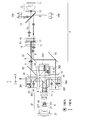
- FIG. 1 is a configuration diagram schematically showing an overall configuration example of an optical system according to a first embodiment of the present disclosure. It is a block diagram which shows schematically an example of the fluorescent substance wheel in the optical system which concerns on 1st Embodiment. It is explanatory drawing which shows an example of a structure and an effect
- the blue band light can be split into two light valves in the configuration example disclosed in Patent Document 1, the polarization of the light emitted from each light valve is orthogonal to each other. This means that the contrast cannot be increased by using a post-polarizer in the projection optical system to be used later, which is a problem in realizing high contrast.
- wavelength separation (color separation) using a dichroic mirror requires steep separation characteristics in the vicinity of the separation wavelength range, and is extremely difficult to manufacture.
- Patent Document 2 Japanese Patent Laid-Open No. 2001-324762
- a method of realizing high wavelength separation efficiency by utilizing the pupil distribution is also known.
- the single plate single light valve
- the filters of the respective colors since the single plate (single light valve) is driven field-sequentially through the filters of the respective colors, the light utilization efficiency as a whole becomes low even though the wavelength separation efficiency is good.
- the present disclosure presents a novel technique of optical separation and photosynthesis using pupil conjugation as a method of optical branching.
- the present technology can be used in various ways, but has the following merits.
- the efficiency can be greatly increased.
- the wavelength separation efficiency can be kept higher than that of the wavelength selection wavelength plate, the light utilization efficiency as a whole can be improved.
- the post-polarizer action can be selectively applied to the light emitted from each light valve, and the contrast can be increased.
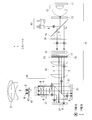
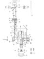
- FIG. 1 schematically shows an overall configuration example of an optical system according to a first embodiment of the present disclosure.
- the first embodiment a configuration example using two light valves is presented.
- the blue light is branched into two light valves to halve the blue light amount and prolong the life.
- the purpose is to increase the contrast.
- the optical system according to the first embodiment includes an illumination optical system 1 and a projection optical system 2. Further, the optical system according to the first embodiment includes a first light valve 31 and a second light valve 32, a PBS (polarized beam) on the optical path between the illumination optical system 1 and the projection optical system 2. Splitter 41).
- the illumination optical system 1 includes a blue light source 10, a phosphor wheel 11, a condenser lens 12, a QWP (1/4 wavelength plate) 13, a wavelength selective PBS 14, a notch filter 15, and a lens array 16. It has a PS converter 17, a first area division wavelength selective wavelength plate 51, and a relay lens 18.
- the projection optical system 2 has a plurality of lenses 21, a second area division wavelength selective wavelength plate 52, and a post polarizer 22.
- the direction orthogonal to the paper surface is S-polarized light for the PBS 41
- the direction orthogonal to the optical axis and parallel to the paper surface is P-polarized light for the PBS 41.
- the direction corresponding to the S-polarized light for the PBS 41 is appropriately referred to as the Z direction
- the direction corresponding to the P-polarized light for the PBS 41 is referred to as the Y direction.
- the illumination optical system 1 corresponds to a specific example of “first optical system” in the technique of the present disclosure.
- the projection optical system 2 corresponds to a specific but not limitative example of “second optical system” in the technology of the present disclosure.
- the first area division wavelength selective wave plate 51 corresponds to a specific but not limitative example of “first optical element” in the technology of the present disclosure.
- the second region division wavelength selective wavelength plate 52 corresponds to a specific but not limitative example of “second optical element” in the technology of the present disclosure.
- the illumination optical system 1 generates illumination light including a plurality of color lights having different wavelength bands.
- the illumination optical system 1 has a wavelength separation function of separating light in at least one wavelength band into a plurality of color lights.
- the illumination optical system 1 generates R, G, and B color lights as a plurality of color lights and emits them toward the PBS 41.
- the first area division wavelength selective wave plate 51 is arranged at the pupil position P1 of the illumination optical system 1.
- the first area-divided wavelength-selective wave plate 51 includes a plurality of divided areas each having a different polarization action.
- the plurality of divided areas in the first area-divided wavelength selective wavelength plate 51 are, for example, areas A and B shown in FIG. 3 described later.
- the PBS 41 makes each color light from the illumination optical system 1 incident on at least one of the first light valve 31 and the second light valve 32 according to the polarization direction.
- the PBS 41 makes the blue light enter the first light valve 31 and the second light valve 32, for example, by branching the blue light according to the difference in polarization.
- the PBS 41 also causes green light to enter one of the first light valve 31 and the second light valve 32 (first light valve 31), for example.
- the PBS 41 also causes red light to enter the other light valve (second light valve 32) of the first light valve 31 and the second light valve 32, for example. Further, the PBS 41 emits each color light modulated by the first light valve 31 and the second light valve 32 toward the projection optical system 2 according to the polarization direction.
- Each of the first light valve 31 and the second light valve 32 modulates at least one color light of the plurality of color lights according to, for example, an image signal.
- Each color light after being modulated by the first light valve 31 and the second light valve 32 enters the projection optical system 2 via the PBS 41.
- the projection optical system 2 projects the image generated by the first light valve 31 and the second light valve 32 onto a projection surface such as a screen (not shown).
- the second area division wavelength selective wavelength plate 52 is arranged at the pupil position P2 of the projection optical system 2.
- the second area-divided wavelength-selective wave plate 52 includes a plurality of divided areas each having a different polarization effect.
- the plurality of divided areas in the second area-divided wavelength selective wavelength plate 52 are, for example, A′ area and B′ area shown in FIG. 4 described later.
- the pupil position P1 of the illumination optical system 1 and the pupil position P2 of the projection optical system 2 are conjugate with each other.
- Each of the plurality of divided areas in the first area-divided wavelength selective wavelength plate 51 and each of the plurality of divided areas in the second area-divided wavelength selective wavelength plate 52 are conjugated with each other.
- the pupil position P1 of the illumination optical system 1 corresponds to a specific example of “first pupil position” in the technique of the present disclosure.
- the pupil position P2 of the projection optical system 2 corresponds to a specific but not limitative example of “second pupil position” in the technique of the present disclosure.
- the post-polarizer 22 is arranged on the emission optical path of the second area division wavelength selective wavelength plate 52.
- FIG. 2 schematically shows a configuration example of the phosphor wheel 11.
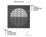
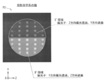
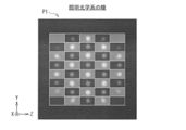
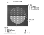
- FIG. 3 shows an example of the configuration and operation of the first area division wavelength selective wave plate 51.
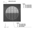
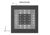
- FIG. 4 shows an example of the configuration and operation of the second area division wavelength selective wave plate 52.
- the blue light source 10 is, for example, a blue laser.
- the phosphor wheel 11 has a phosphor region 111 and a polarization maintaining diffusion plate region 112. By irradiating the phosphor region 111 with blue light as excitation light, yellow (Ye) light is obtained.
- the polarization maintaining diffusion plate region 112 has a reflecting function for blue light without a polarizing effect. For this reason, the phosphor wheel 11 emits time-averaged white light that is a temporal repetition of yellow, blue, yellow, blue,....
- the blue light emitted from the blue light source 10 is reflected by the wavelength-selective PBS 14, passes through the quarter-wave plate 13 to become circularly polarized light, and then enters the phosphor wheel 11 via the condenser lens 12. ..
- the light emitted from the phosphor wheel 11 passes through the quarter-wave plate 13 again to be converted into P-polarized light for the wavelength-selective PBS 14. Then, the light is emitted to the transmission side by the wavelength-selective PBS 14.
- the yellow light extracted from the phosphor wheel 11 is also reflected and then emitted to the transmission side by the wavelength selective PBS 14.
- the yellow light generated by the phosphor wheel 11 is in a non-polarized state, and the wavelength selective PBS 14 has a function of transmitting all the yellow light.
- the blue light and the yellow light emitted from the wavelength-selective PBS 14 pass through the notch filter 15 and the lens array 16 and then pass through the PS converter 17 so that the polarization state is one direction (for example, polarization in the Y direction (P-polarized light here). )).
- the first area-divided wavelength selective wavelength plate 51 having the characteristics as shown in FIG. 3 is arranged in the portion where the pupil (first pupil) of the illumination optical system 1 is formed.
- the first region-divided wavelength-selective wave plate 51 is, for example, a 1/2 wave plate arranged in an oblique 45 deg where the upper half (A region) acts only on green, and the lower half (B region) is green.
- the polarized light of blue light is in a mixed state of polarized light that does not rotate (polarized light in the Y direction (P polarized light)) and polarized light that rotates (polarized light in the Z direction (S polarized light)).
- each color light After passing through the first area-divided wavelength-selective wave plate 51, when the light flux of each color reaches the PBS 41 through the relay lens 18, each color light is selectively emitted in accordance with each polarization state of the first light valve 31 and the second light valve 31. It is led to the light valve 32.
- the red light is P-polarized light and reaches the second light valve 32
- the green light is S-polarized light and reaches the first light valve 31.
- the blue light is in a mixed state of P-polarized light and S-polarized light, and reaches the first light valve 31 and the second light valve 32 in half and half.
- the first light valve 31 and the second light valve 32 When a reflective liquid crystal is used for the first light valve 31 and the second light valve 32, when the white display is performed by each light valve, each polarization rotation occurs, and each incident polarization becomes an exit polarization in an orthogonal state. Changes. Therefore, the first light valve 31 emits red light and blue light as S-polarized light, and the second light valve 32 emits blue light and red light as P-polarized light. Therefore, when white display is performed, all the light passing through the PBS 41 is emitted to the projection optical system 2 side.
- the PBS 41 tends to have a slightly larger Rp (reflection P polarization component) than Ts (transmission S polarization component) due to the characteristics of the polarizing film. Therefore, the second light valve 32 side tends to have less contrast than the first light valve 31 side. This is because more P-polarized light generated by the second light valve 32 leaks to the projection optical system 2 side than S-polarized light generated by the first light valve 31 during black display.
- the contrast is increased, and only the first light valve 31 side is used.
- the contrast is greatly increased. It becomes a factor to lose.
- the post-polarizer 22 (after injection of the PBS 41 is used. It is necessary to align the direction of polarization with the analyzer (1) to improve the contrast.
- the post-polarizer 22 is arranged immediately after the PBS 41 without devising, the amount of light will be halved because the polarization states of blue light are orthogonal.
- the greatest feature of the optical system according to the first embodiment is to improve this by utilizing the conjugate action of the pupil.
- the second area division wavelength selective wavelength plate 52 is arranged at the pupil (second pupil) position P2 of the projection optical system 2 after the emission from the PBS 41. ..
- the dividing method at this time is shown in FIG.
- the pupil of the projection optical system 2 is conjugate with the pupil of the illumination optical system 1, and since it passes through the light valve reflection, the vertical inversion corresponds to each conjugate part in a region. Therefore, as shown in FIG. 4, the area conjugate to the area A of the first area-divided wavelength-selective wave plate 51 is the A′ area below the second area-divided wavelength-selective wave plate 52.
- the region conjugate to the B region of the first region-divided wavelength selective wavelength plate 51 is the B′ region above the second region-divided wavelength selective wavelength plate 52.
- Conjugation means that light that has passed through the area A of the first area-divided wavelength-selective wave plate 51 always passes through the area A′ of the second area-divided wavelength-selective wave plate 52 and has the first area-divided wavelength selectivity.
- Light that has passed through the B region of the wave plate 51 always passes through the B′ region of the second area-divided wavelength selective wave plate 52. Therefore, of the mixed blue light, the P-polarized light is selectively incident on the B'region and the S-polarized light is selectively incident on the A'region.
- the polarization of the blue light is not converted in the A'region, and the polarization of the blue light is rotated by 90 deg in the B'region.
- the polarized light of the red light does not rotate and the polarized light of the green light rotates by 90 deg in any of the regions, as a result, the polarized light of each color light after passing through the second area-divided wavelength selective wavelength plate 52 becomes S-polarized light. Will be unified.
- the contrast can be improved by arranging the post polarizer 22 so as to cut the P-polarized light after passing through the second area-divided wavelength-selective wave plate 52.
- an experimental result of white contrast of about 1000:1 at F/2.5 was obtained, and the amount of blue light was about half each. It was confirmed that the first light valve 31 and the second light valve 32 could be branched to exhibit the expected operation.
- the main purpose of this is to divide the blue light, which is the cause of shortening the life of the light valve, into two, thereby reducing the amount of incident light by half and significantly improving the life of the entire optical system. In this sense, it is desirable that the light split into two is 500 nm or less.
- Patent Document 3 Japanese Patent Laid-Open No. 2008-165058.
- a region-divided retardation plate is arranged in the vicinity of the pupil in the projection optical system, and light is split into two by polarized light in the projection optical system.
- the pupil position P1 of the illumination optical system 1 includes the first area division wavelength including the plurality of division areas having different polarization effects.
- the optical system according to the first embodiment it is possible to increase the contrast, and it is possible to prevent color unevenness on the projection surface by aligning the polarization of the final emitted light in the projection optical system 2 in one direction. Further, since the contrast can be increased for one PBS 41 while using two light valves, it is possible to reduce the size of the entire optical system as a result.
- the notch filter 15 is an essential component in the illumination optical system 1. The role of the notch filter 15 will be described with reference to FIGS.
- FIG. 5 shows an example of the fluorescence spectrum of the YAG phosphor used in the phosphor wheel 11 in the optical system according to the first embodiment.
- FIG. 6 shows wavelength selection characteristics of the B area of the first area-divided wavelength selective wavelength plate 51 and the B′ area of the second area-divided wavelength selective wavelength plate 52 in the optical system according to the first embodiment. Shows an example.
- FIG. 7 shows the wavelength selection characteristics of the A area of the first area-divided wavelength selective wavelength plate 51 and the A′ area of the second area-divided wavelength selective wavelength plate 52 in the optical system according to the first embodiment. Shows an example.
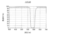
- FIG. 8 shows an example of the characteristics of the notch filter 15 in the optical system according to the first embodiment.
- the polarized light of each color is selectively rotated.
- a problem is the switching region between red and green of 575 nm to 610 nm.
- the conversion efficiency of this portion is not 100% for any polarized light, so that an unintended polarization component appears.
- An unintended polarized component becomes polarized light that cannot be blocked by the post-polarizer 22, which causes a sharp deterioration in contrast.
- the notch filter 15 having the characteristic shown in FIG.
- FIG. 9 shows an example of the fluorescence spectrum after the action of the notch filter 15. It can be seen that there is a considerable spectrum loss as compared with FIG. Further, also in the regions A and A′ shown in FIG. 7, switching between red and green occurs in the region of approximately 575 nm to 610 nm, and shielding of this part is important.
- FIG. 10 schematically shows an example of the overall configuration of the optical system according to the second embodiment.
- the optical system according to the first embodiment includes an illumination optical system 1A and a projection optical system 2A.
- the illumination optical system 1A is different from the configuration of the illumination optical system 1 (FIG. 1) in the first embodiment, in that it replaces the first area division wavelength selective wavelength plate 51 with the pupil position P1 of the illumination optical system 1A.
- the dichroic converter 61 is arranged in the position. Further, the illumination optical system 1A has a configuration in which the notch filter 15 is omitted and a 1/2 wavelength plate 19 is arranged after the wavelength selective PBS 14 in addition to the configuration of the illumination optical system 1 in the first embodiment. ing.
- the dichroic converter 61 includes a plurality of divided areas each having a different polarization effect. The wavelength distributions in each of the plurality of divided areas at the pupil position P1 of the illumination optical system 1A are different from each other.
- the plurality of divided areas in the dichroic converter 61 are, for example, area C and area D shown in FIG. 12, which will be described later.
- the post polarizer 22 is omitted from the configuration of the projection optical system 2 (FIG. 1) in the first embodiment, and instead of the second area division wavelength selective wavelength plate 52,
- the area dividing polarizer 62 is arranged at the pupil position P2 of the projection optical system 2A.
- the area division polarizer 62 includes a plurality of division areas each having a different polarization effect.
- the area division polarizer 62 has a function of transmitting lights having polarization directions different from each other in each of the plurality of division areas.
- the plurality of divided areas in the area-divided polarizer 62 are, for example, a C′ area and a D′ area shown in FIG. 13 described later.
- the area-divided polarizer 62 functions as an area-divided post-polarizer.
- the illumination optical system 1A corresponds to a specific but not limitative example of “first optical system” in the technology of the present disclosure.
- the projection optical system 2A corresponds to a specific but not limitative example of “second optical system” in the technology of the present disclosure.
- the dichroic converter 61 corresponds to a specific but not limitative example of “first optical element” in the technique of the present disclosure.
- the area division polarizer 62 corresponds to a specific but not limitative example of “second optical element” in the technology of the present disclosure.
- the half-wave plate 19 can convert the polarization state of blue light so that the polarization in the Y direction (P polarization) and the polarization in the Z direction (S polarization) are equal.
- the respective color lights entering the PS converter 17 have a polarization state in which the P polarization and the S polarization are in the same state.
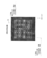
- FIG. 11 schematically shows a configuration example of the PS converter 17 and the dichroic converter 61 in the optical system according to the second embodiment.
- the PS converter 17 has a plurality of prism blocks on which a polarizing film 171 is formed.
- shield regions 173 are formed every other one of the plurality of prism blocks in the Y direction.
- a half-wave plate 172 is formed every other prism block in the Y direction.
- the shielding region 173 and the half-wave plate 172 are formed in the same prism block among a plurality of prism blocks.
- the dichroic converter 61 has a plurality of prism blocks.
- the plurality of prism blocks include a first prism block having a dichroic film 611 formed thereon and a second prism block having a total reflection film 614 formed thereon, and the first prism block and the second prism block. And are arranged alternately in the Y direction.
- a half-wave plate 612 is formed on the light exit surface along the X direction of the first prism block on which the dichroic film 611 is formed.
- a shielding region 613 is formed on the light incident surface along the X direction of the second prism block on which the total reflection film 614 is formed.
- the dichroic converter 61 is arranged adjacent to the PS converter 17.
- the PS converter 17 receives unpolarized light, of which the P-polarized component is transmitted and the S-polarized component is reflected. Since the prism block in the PS converter 17 is a polarizing prism, the S polarization component reflected by the polarizing film 171 of a certain prism block is further reflected by the polarizing film 171 of another prism block and passes through the 1 ⁇ 2 wavelength plate 172. By doing so, the P-polarized component is converted again. As a result, the PS converter 17 can convert polarized light.
- the PS converter 17 is arranged on the exit side of the lens array 16, and a shield region 173 is provided between the formed point images to realize the polarization conversion while suppressing the light amount loss. Further, the dichroic converter 61 exerts a color conversion function on the light passing through the PS converter 17. On the prism block forming the dichroic converter 61, dichroic films 611 and total reflection films 614 are alternately formed. On the side of the dichroic film 611, red light is reflected and 50% of blue light is reflected, green light is transmitted, and further 50% of blue light is transmitted. The total reflection film 614 has a function of reflecting all light.
- the light reflected from the dichroic film 611 and further reflected from the total reflection film 614 is converted into green-blue light and red-blue light by passing through the 1 ⁇ 2 wavelength plate 612 that rotates the polarization direction by 90 deg.
- the polarizations may be orthogonal to each other.
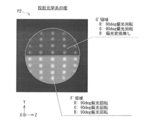
- FIG. 12 shows an example of the polarization state in the pupil of the illumination optical system 1A of the optical system according to the second embodiment.
- the divided C area and D area are staggered in the vertical direction.
- the C region corresponds to the region in which the half-wave plate 612 is formed in the dichroic converter 61 shown in FIG.
- the D region corresponds to a region in which the half-wave plate 612 is not formed in the dichroic converter 61 shown in FIG.
- the light passing through the C region is composed of red light having a light amount of 100% and blue light having a light amount of 50%, and the polarization direction is the Y direction (P polarized light).
- the light passing through the region D is composed of green light with a light amount of 100% and blue light with a light amount of 50%, and the polarization direction is the Z direction (S polarization).
- the light emitted from the region C reaches the second light valve 32 because the polarization direction is the Y direction.
- the light emitted from the region D reaches the first light valve 31 because the polarization direction is the Z direction.
- the lights converted into the orthogonal polarizations by the first light valve 31 and the second light valve 32 are subjected to the action of each divided area by the area dividing polarizer 62 in the pupil of the projection optical system 2A. ..
- FIG. 13 shows an example of the polarization state in the pupil of the projection optical system 2A of the optical system according to the second embodiment.
- the divided C'region and D'region are staggered in the vertical direction.
- the portion of the C′ area at the pupil position P2 of the projection optical system 2A is conjugate with the C area at the pupil position P1 of the illumination optical system 1A, and the conjugate of the D area at the pupil position P1 of the illumination optical system 1A is projected.
- This is a portion of the D'region at the pupil position P2 of the optical system 2A. Therefore, only the Y direction (P polarized light) reaches the C'region and only the Z direction (S polarized light) reaches the D'region.
- the area dividing polarizer 62 is provided so that the C′ region is given the polarizer effect of Y direction polarized light transmission and Z direction polarized light shielding, and the D′ region is given the Z direction polarized light transmission and Y direction polarized light shielding polarizer effect.
- the effect as each post polarizer can be given to the first light valve 31 and the second light valve 32, and the contrast can be increased.
- An advantage of the configuration of the optical system according to the second embodiment is that the notch filter 15 is not needed because the first area division wavelength selective wave plate 51 is not used.
- the post-polarizer 22 blocks in the red-green switching area. It can't function as a perfect post-polarizer because it produces polarized light in different directions, which is impossible.
- the conversion of reflection and transmission depending on the polarization direction is not perfect in the switching region between red and green, but the illumination optical system 1A In the pupil, the polarization direction generated depends on whether the light is guided to the C region or the D region.
- the light emitted from the C area is always guided to the C′ area of the pupil of the projection optical system 2A, and the light emitted from the D area is always guided to the D′ area of the pupil of the projection optical system 2A.
- the post-polarizer region-dividing polarizer 62
- the notch filter 15 is not necessary for increasing the contrast. In other words, it is an advantage that the incomplete conversion in the switching region between red and green is not pressed against the polarized light.
- FIG. 14 shows an example of a spectrum of light reaching the first and second light valves 31 and 32 in the optical system according to the second embodiment. It can be seen that the lights in the red and green switching regions are mixed and assigned to each light valve.
- the polarization of each light valve is unidirectional, and mixing of polarization does not occur in principle.
- the light amount loss caused by the notch filter 15 used in the optical system according to the first embodiment is eliminated, and the brightness is improved by about 30%, and the contrast and the panel light resistance are improved. Can be combined.
- the contrast of 1000:1 similar to that of the optical system according to the first embodiment is expected in principle.
- the first area-divided wavelength selective wavelength plate 51 is replaced by the dichroic converter 61, so that the first area-divided wavelength selective wavelength plate is replaced. It is possible to eliminate the conversion loss caused by 51 and maintain a high contrast while greatly increasing the brightness.
- FIG. 15 schematically shows an example of the overall configuration of the optical system according to the third embodiment.
- the configuration example of the optical system capable of improving the contrast while suppressing the light amount loss is shown.
- the PS converter 17 since the PS converter 17 has the shielding region 173, the dichroic converter which is in contact with the PS converter 17 is actually used.
- the loss of the angle component is likely to be large.
- the optical system according to the third embodiment includes an illumination optical system 1B and a projection optical system 2B.
- the illumination optical system 1B has a first lens array 16A and a second lens array 16B instead of the lens array 16 in addition to the configuration of the illumination optical system 1A (FIG. 10) in the second embodiment. doing. Further, the illumination optical system 1B has a first relay lens 18A and a second relay lens 18B instead of the relay lens lens 18 in the configuration of the illumination optical system 1A in the second embodiment. ing. Further, the illumination optical system 1B has a configuration in which the half-wave plate 19 is omitted from the configuration of the illumination optical system 1A in the second embodiment.
- the projection optical system 2B has the same configuration as the projection optical system 2A (FIG. 10) in the second embodiment.
- the illumination optical system 1B corresponds to a specific but not limitative example of “first optical system” in the technology of the present disclosure.
- the projection optical system 2B corresponds to a specific but not limitative example of “second optical system” in the technology of the present disclosure.
- the optical system according to the third embodiment is different from the optical system according to the second embodiment in that the PS converter 17 and the dichroic converter 61 are separated, and the second relay lens 18B and the second relay lens 18B are provided between them.
- the system is such that it is connected to the second lens array 16B.
- uniform illumination is once formed by the first lens array 16A, the PS converter 17, and the second relay lens 18B, and again, the second lens array 16B, the dichroic converter 61, and the first relay lens.
- 18A produces uniform illumination for the first light valve 31 and the second light valve 32.
- the subsequent configuration and operation are similar to those of the optical system according to the second embodiment, and the contrast can be increased by using pupil conjugation.
- the pitches of the PS converter 17 and the dichroic converter 61 can be matched, and as a result, the shielding area 173 of the PS converter 17 can be made smaller, so that the above-mentioned Etendue Since there are almost no problems, the light utilization efficiency can be greatly increased while suppressing the volume of the entire system.
- FIG. 16 shows an example of the pupil shape of the illumination optical system 1A or the projection optical system 2A of the optical system according to the second embodiment as a comparative example with respect to the optical system according to the third embodiment.
- FIG. 17 shows an example of the pupil shape of the illumination optical system 1B or the projection optical system 2B of the optical system according to the third embodiment.
- the pupil shape in the optical system according to the second embodiment is substantially circular.
- the image in front of the second lens array 16B formed by the first lens array 16A becomes a pupil shape. Therefore, it is almost square. This may adversely affect laser safety standards and the like. In order to solve this, it is more preferable to adopt the configuration of the optical system according to the fourth embodiment described later.
- the pupil distribution for blue light is the same as the pupil distribution for yellow light even when the polarization maintaining diffusion plate region 112 of the phosphor wheel 11 has a simple total reflection configuration. It also has the advantages of cost reduction and simplification of the manufacturing process.
- FIG. 18 schematically shows an example of the overall configuration of the optical system according to the fourth embodiment.
- the optical system according to the fourth embodiment includes an illumination optical system 1C and a projection optical system 2C.
- the illumination optical system 1C includes a first lens array 16A, a second lens array 16B, and a third lens array 16A instead of the lens array 16 in the configuration of the illumination optical system 1A (FIG. 10) in the second embodiment.
- Lens array 16C the illumination optical system 1C is different from the configuration of the illumination optical system 1A in the second embodiment, in place of the relay lens lens 18, a first relay lens 18A, a second relay lens 18B, and a third relay lens 18A. It has a relay lens 18C.
- the illumination optical system 1C has a configuration in which the half-wave plate 19 is omitted from the configuration of the illumination optical system 1A in the second embodiment.
- the projection optical system 2C has the same configuration as the projection optical system 2A (FIG. 10) in the second embodiment.
- the illumination optical system 1C corresponds to a specific but not limitative example of “first optical system” in the technology of the present disclosure.
- the projection optical system 2C corresponds to a specific but not limitative example of “second optical system” in the technology of the present disclosure.
- the optical system according to the fourth embodiment has a relay of the illumination optical system 1C as shown in FIG.
- the lens system has three stages.
- the first lens array 16A is a rectangular lens array
- the second lens array 16B is a hexagonal lens
- the third lens array 16C is a rectangular lens array.
- the first lens array 16A, the PS converter 17, and the third relay lens 18C have a polarization rectifying function.
- the second lens array 16B and the second relay lens 18B generate hexagonal illumination (this becomes a pupil later).
- the third lens array 16C, the dichroic converter 61, and the first relay lens 18A have a function of separating colors, a polarization conversion action for each light valve, and a function of producing uniform rectangular illumination for each light valve.
- the subsequent configuration and operation are similar to those of the second embodiment, and the contrast can be increased by using pupil conjugation.
- FIG. 19 shows an example of the pupil shape of the illumination optical system 1C or the projection optical system 2C of the optical system according to the fourth embodiment.
- the pupil shape can be made to have a configuration close to a hexagon, and the quadrangular shape which is a problem in the above-described third embodiment. You can avoid becoming an eye.
- the optical system according to the fourth embodiment may have a configuration in which the polarization maintaining/diffusing plate region 112 on the phosphor wheel 11 is simply reflected, similarly to the optical system according to the third embodiment. It is possible.
- FIG. 20 schematically shows an example of the overall configuration of the optical system according to the fifth embodiment.
- the optical system according to the fifth embodiment includes an illumination optical system 1D and a projection optical system 2D.
- the illumination optical system 1D is different from the configuration of the illumination optical system 1 (FIG. 1) in the first embodiment, in place of the first area division wavelength selective wavelength plate 51, and the pupil position P1 of the illumination optical system 1D.
- the area division wavelength plate 71 is arranged in the area. Further, the illumination optical system 1D has a configuration in which the notch filter 15 is omitted and a 1 ⁇ 2 wavelength plate 19 is disposed after the wavelength selective PBS 14 in addition to the configuration of the illumination optical system 1 in the first embodiment. ing.
- the area division wavelength plate 71 includes a plurality of division areas each having a different polarization effect. The plurality of divided areas in the area-divided wavelength plate 71 are, for example, a D area and an E area shown in FIG. 21 described later.
- the post polarizer 22 is omitted from the configuration of the projection optical system 2 (FIG. 1) in the first embodiment, and instead of the second area division wavelength selective wavelength plate 52,
- the area dividing polarizer 62 is arranged at the pupil position P2 of the projection optical system 2D.
- the area division polarizer 62 includes a plurality of division areas each having a different polarization effect.
- the area division polarizer 62 has a function of transmitting lights having polarization directions different from each other in each of the plurality of division areas.
- the plurality of divided areas in the area division polarizer 62 are, for example, a D′ area and an E′ area shown in FIG. 22, which will be described later.
- the area-divided polarizer 62 functions as an area-divided post-polarizer.
- the illumination optical system 1D corresponds to a specific but not limitative example of “first optical system” in the technology of the present disclosure.
- the projection optical system 2D corresponds to a specific but not limitative example of “second optical system” in the technology of the present disclosure.
- the area division wavelength plate 71 corresponds to a specific but not limitative example of “first optical element” in the technology of the present disclosure.
- the area division polarizer 62 corresponds to a specific but not limitative example of “second optical element” in the technology of the present disclosure.
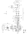
- the optical system according to the fifth embodiment can be configured as a 3D (three-dimensional) display device by further including polarization glasses 4 and a polarization maintaining screen 5. An image for the right eye and an image for the left eye are projected on the polarization maintaining screen 5 via the projection optical system 2D.
- the light incident on the PS converter 17 is polarized in the Y direction (P polarized light) and in the Z direction with respect to all colors by previously inserting the 1 ⁇ 2 wavelength plate 19. (S-polarized light) is equal.
- a broadband area-divided wavelength plate 71 having no wavelength selectivity is used, and For the three-dimensional display, the light is divided into all the red, green, and blue color lights.
- the area dividing polarizer 62 is arranged at the pupil position P2 of the projection optical system 2D to increase the contrast while maintaining the polarized light for the right eye and the polarized light for the left eye.
- the polarizing glasses 4 are orthogonal polarizer glasses, and the user can observe the image for the right eye and the image for the left eye projected on the polarization maintaining screen 5 as three-dimensional images by wearing the polarizing glasses 4. It will be possible.
- FIG. 21 shows an example of the polarization state in the pupil of the illumination optical system 1D of the optical system according to the fifth embodiment.
- the area division wavelength plate 71 is vertically divided into a D area and an E area.
- the polarizations of all the color lights are rotated by 90 deg, and in the E region, the polarizations of all the color lights are not rotated at all.
- all the light passing through the D region can reach the first light valve 31, and all the light passing through the E region can reach the second light valve 32.
- the right eye channel and the second light valve 32 can be used as the left eye channel.
- FIG. 22 shows an example of the polarization state in the pupil of the projection optical system 2D of the optical system according to the fifth embodiment.
- the area division polarizer 62 is vertically divided into an E′ area and a D′ area.
- the portion of the D'region at the pupil position P2 of the projection optical system 2D is conjugate with the D region at the pupil position P1 of the illumination optical system 1D, and the conjugate is at the E region of the pupil position P1 of the illumination optical system 1D at the pupil region P1. This is a portion of the E′ region at the pupil position P2 of the optical system 2D.
- the projection optical system 2D all the light from the first light valve 31 reaches the D'region, and the contrast is increased by the action of the polarizer that transmits only the polarized light in the Y direction (P polarized light).
- all the light from the second light valve 32 reaches the E′ region, and the contrast is increased by the action of the polarizer that transmits only the polarized light in the Z direction (S polarized light).
- the optical system according to the fifth embodiment is a two-plate optical system that is compact and can increase the contrast to a practical range, and can also perform polarized three-dimensional display. Therefore, the polarizing glasses 4 can be simplified and lightened, and the entire system can be realized. It is possible to assemble at low cost.
- optical system according to the fifth embodiment does not mean that the boundary between green and red is polarized differently, so the notch filter 15 is unnecessary.
- optical system of the fifth embodiment it is possible to increase the contrast even during three-dimensional display and reduce the amount of crosstalk between the left and right eyes.
- FIG. 23 schematically shows an example of the overall configuration of the optical system according to the sixth embodiment.
- the optical system according to the sixth embodiment includes an illumination optical system 1E and a projection optical system 2E. Further, the optical system according to the sixth embodiment includes two blue light valves 3B1 and 3B2 and one red light valve 3R1 on the optical path between the illumination optical system 1E and the projection optical system 2E. It is provided with one green light valve 3G1, PBSs 41, 42, 43 and a dichroic cube 44.
- the illumination optical system 1E includes a first blue light source 10A, a second blue light source 10B, a phosphor wheel 11, a condenser lens 12, a 1/4 wavelength plate 13, a wavelength selective PBS 14, and a lens array. 16, a PS converter 17, a first area division wavelength selective wavelength plate 51, and a relay lens 18. Further, the illumination optical system 1E has a first color plate 81, a second color plate 82, and a total reflection mirror 83.
- the projection optical system 2E has the same configuration as the projection optical system 2 (FIG. 1) in the first embodiment.
- the illumination optical system 1E corresponds to a specific but not limitative example of “first optical system” in the technology of the present disclosure.
- the projection optical system 2E corresponds to a specific but not limitative example of “second optical system” in the technology of the present disclosure.
- the first area division wavelength selective wave plate 51 corresponds to a specific but not limitative example of “first optical element” in the technology of the present disclosure.
- the second region division wavelength selective wavelength plate 52 corresponds to a specific but not limitative example of “second optical element” in the technology of the present disclosure.
- the PBS 41 corresponds to a specific example of “polarization separation element” in the technique of the present disclosure.
- the PBS 41 is provided on the optical path of the blue light emitted from the illumination optical system 1E, and branches the blue light according to the difference in polarization so that the blue light is incident on the blue light valve 3B1 and the blue light valve 3B2.
- the PBS 42 is provided on the optical path of the red light emitted from the illumination optical system 1E, and causes the red light to enter the red light valve 3R1.
- the PBS 43 is provided on the optical path of the green light emitted from the illumination optical system 1E, and causes the green light to enter the green light valve 3G1.
- the dichroic cube 44 synthesizes the respective color lights modulated by the respective light valves and emits them toward the projection optical system 2E.
- the optical system according to the sixth embodiment has a three-plate configuration of R, G, and B as a basic configuration, and two light valves (blue light valves 3B1 and 3B2) are arranged only for the B channel as a light resistance measure. doing.
- the polarization maintaining diffusion plate region 112 (FIG. 2) is not provided in the phosphor wheel 11, and the blue light from the first blue light source 10A emits fluorescence.
- the body region 111 is continuously irradiated.
- the yellow light is continuously emitted from the phosphor wheel 11 instead of being time-divided.
- Blue light is continuously emitted from the second blue light source 10B.
- the blue light from the second blue light source 10B is reflected by the wavelength selective PBS 14 and combined with the yellow light from the phosphor wheel 11.
- each light valve is dedicated to each color, and color time division is not performed.
- FIG. 24 shows an example of the polarization state in the pupil of the illumination optical system 1E of the optical system according to the sixth embodiment.
- the first area division wavelength selective wave plate 51 is vertically divided into an F area and a G area.
- the F region rotates the polarized light by 90 deg regardless of the R, G, and B colors, and in the G region, only the blue light is not polarization-converted, and the other colored light is rotated by 90 deg.
- the blue light entering the light valve is halved, and the service life of the system can be extended.
- the red light and the green light are branched by the first color plate 81 and the second color plate 82, and are respectively led to the red light valve 3R1 and the green light valve 3G1.
- the red light and the green light are incident on S-polarized light, and the emitted light is P-polarized light.
- the R, G, and B color lights emitted from the light valves are combined by the dichroic cube 44 and guided to the projection optical system 2E.
- the polarization directions at this time are Y-direction polarization (P-polarization) for red light and green light when incident on the projection optical system 2E, and Y-direction polarization (P-polarization) and Z-direction polarization (S-polarization) for blue light. And are mixed.
- FIG. 25 shows an example of the polarization state in the pupil of the projection optical system 2E of the optical system according to the sixth embodiment.
- the second area-divided wavelength selective wavelength plate 52 is vertically divided into a G′ area and an F′ area.
- the F region at the pupil position P1 of the illumination optical system 1E is conjugate to the F′ region at the pupil position P2 of the projection optical system 2E
- the G region at the pupil position P1 of the illumination optical system 1E is conjugated to the region. This is a part of the G'region at the pupil position P2 of the optical system 2E.
- In the pupil position P2 of the projection optical system 2E in the F'region which is conjugate with the F region, all color light is rotated by 90 deg polarization and converted into Z-direction polarization (S polarization).
- the red light and the green light are rotated by 90 deg, the blue light is not polarization-converted, and as a result, all the color light is converted to the Z-direction polarization (S-polarization).
- the contrast can be increased by finally rectifying this using the post polarizer 22 in the projection optical system 2E.
- the optical system according to the sixth embodiment has a feature that it can be extended in life while suppressing the number of light valves, and has a feature that it can be configured relatively inexpensively.
- the point of the optical system according to the sixth embodiment is that the contrast can be increased by the post-polarizer 22 while using two polarized lights orthogonal to each other with respect to a specific wavelength, and different configurations can be used. ..
- the switching region between green and red is not switched by the region-divided wavelength-selective wave plate, so the notch filter 15 is unnecessary.
- FIG. 26 schematically shows an example of the overall configuration of the optical system according to the seventh embodiment.
- the optical system according to the seventh embodiment includes an illumination optical system 1F and a projection optical system 2F.
- the optical system according to the seventh embodiment has two blue light valves 3B1 and 3B2 and two red light valves 3R1 on the optical path between the illumination optical system 1F and the projection optical system 2F. 3R2, two green light valves 3G1 and 3G2, PBSs 41, 42 and 43, and a dichroic cube 44.
- the illumination optical system 1F includes a first blue light source 10A, a second blue light source 10B, a phosphor wheel 11, a condenser lens 12, a 1/4 wavelength plate 13, a wavelength selective PBS 14, and a lens array. 16, a PS converter 17, a region division wavelength plate 71, and a relay lens 18. Further, the illumination optical system 1F has a first color plate 81, a second color plate 82, and a total reflection mirror 83.
- the projection optical system 2F has the same configuration as the projection optical system 2D (FIG. 20) in the fifth embodiment, and the area dividing polarizer 62 is arranged at the pupil position P2.
- the illumination optical system 1F corresponds to a specific but not limitative example of “first optical system” in the technology of the present disclosure.
- the projection optical system 2F corresponds to a specific but not limitative example of “second optical system” in the technology of the present disclosure.
- the first area division wavelength selective wave plate 51 corresponds to a specific but not limitative example of “first optical element” in the technology of the present disclosure.
- the area division polarizer 62 corresponds to a specific but not limitative example of “second optical element” in the technology of the present disclosure.
- the two blue light valves 3B1 and 3B2 correspond to a specific example of “first and second light valves” in the technology of the present disclosure.
- the two red light valves 3R1 and 3R2 correspond to a specific example of “third and fourth light valves” in the technique of the present disclosure.
- it corresponds to one specific example of the two green light valves 3G1 and 3G2 and the “fifth and sixth light valves” in the technique of the present disclosure.
- the PBS 41 is provided on the optical path of the blue light emitted from the illumination optical system 1F, and branches the blue light according to the polarization difference to make it enter the blue light valve 3B1 and the blue light valve 3B2.
- the PBS 42 is provided on the optical path of the red light emitted from the illumination optical system 1F, and branches the red light according to the difference in polarization so that the red light is incident on the red light valve 3R1 and the red light valve 3R2.
- the PBS 43 is provided on the optical path of the green light emitted from the illumination optical system 1F, and branches the green light according to the difference in polarization so that the green light is incident on the green light valve 3G1 and the green light valve 3G2.
- the dichroic cube 44 synthesizes the respective color lights modulated by the respective light valves and emits them toward the projection optical system 2F.
- the optical system according to the seventh embodiment has two light valves arranged for each color of R, G, and B. Further, in the optical system according to the seventh embodiment, the phosphor wheel 11 is not provided with the polarization maintaining/diffusing plate region 112 (FIG. 2) as in the optical system according to the sixth embodiment. Instead, the blue light from the first blue light source 10A is continuously applied to the phosphor region 111. As a result, the yellow light is continuously emitted from the phosphor wheel 11 instead of being time-divided. Blue light is continuously emitted from the second blue light source 10B. The blue light from the second blue light source 10B is reflected by the wavelength selective PBS 14 and combined with the yellow light from the phosphor wheel 11. In the optical system according to the seventh embodiment, like the optical system according to the sixth embodiment, each light valve is dedicated to each color, and color time division is not performed.
- the polarization state in the pupil of the illumination optical system 1F in the seventh embodiment is the same as that in the optical system according to the fifth embodiment, and at the pupil position P1 of the illumination optical system 1F, the area division wavelength plate 71 moves up and down. It is divided into a D area and an E area (FIG. 21). Thereby, for each color, two orthogonal polarization states are created at the position P1 of the illumination optical system 1F, and the two polarization states are made incident on the light valve of each color according to each polarization state.
- the polarization state in the pupil of the projection optical system 2F in the seventh embodiment is similar to that in the optical system according to the fifth embodiment, and at the pupil position P2 of the projection optical system 1F, the area division polarizer 62 moves up and down. Is divided into an E'region and a D'region (Fig. 22).
- the area dividing polarizer 62 is provided at the pupil position P2 of the projection optical system 2F and the conjugate action of the pupil is used. , Contrast is increased by utilizing the fact that only polarized light in one direction enters each region for each color.
- the six-element structure described above can realize three-dimensional display using polarized light as in the optical system according to the fifth embodiment.
- the notch filter 15 is not necessary because the switching region between green and red is not switched by the region division wavelength selective wave plate.
- FIG. 27 schematically shows a first division example of the area division wavelength plate 71 in the optical system according to the eighth embodiment.
- FIG. 28 schematically shows a second division example of the area division wavelength plate 71 in the optical system according to the eighth embodiment.
- FIG. 29 schematically shows a third division example of the area division wavelength plate 71 in the optical system according to the eighth embodiment.
- FIG. 30 schematically shows a fourth division example of the area division wavelength plate 71 in the optical system according to the eighth embodiment.
- the area division wavelength plate 71 is arranged at the pupil position P1 of the illumination optical systems 1D and 1F. In such a configuration using the area division wavelength plate 71, there is a considerable degree of freedom in the area division method.
- Some modified examples are shown in FIGS. 27 to 30, but the area dividing method is not limited to these.
- the area may be divided vertically into two.
- the center line divides the point image into two
- the element arrangement at the pupil position P1 of the illumination optical systems 1D and 1F and the element arrangement at the pupil position P2 of the projection optical systems 2D and 2F are mutually separated. It is assumed that the manufacturing tolerance of the positional relationship will become tight.
- the PBS 41 and the like are divided into the right and left, color shading may occur, and rather, the upper and lower divisions in which there is no polarity with respect to the PBS 41 and the like are preferable.
- the light flux in the central region of the pupil has a relatively shallow incident angle with respect to the light valve, which may be advantageous in designing the PBS 41 and the like.
- the method of division is completely within the scope of design, and can be freely designed depending on manufacturability, shading of the PBS 41 and the like, shading in the pupils of the projection optical systems 2D and 2F, or the degree of color unevenness due to projection polarization. ..
- the conjugate pupils in the projection optical systems 2D and 2F need to have operators corresponding to the respective parts.
- the first area division wavelength selective wavelength plate 51 and the PS converter 17 are arranged at the pupil position P1 of the illumination optical system 1 and in the vicinity thereof.
- the PS converter 17 has a good compatibility with the area-divided wavelength-selective wave plate, and both can be integrated.
- FIG. 31 schematically shows a configuration example of the first area division wavelength selective wavelength plate 51A integrated in the PS converter 17A.
- FIG. 32 schematically shows an example of the overall configuration of the optical system according to the ninth embodiment, which uses the first area division wavelength selective wavelength plate 51A.
- the optical system according to the ninth embodiment includes an illumination optical system 1G and a projection optical system 2G.
- the illumination optical system 1G is different from the configuration of the illumination optical system 1 (FIG. 1) in the first embodiment in that the pupil area P1 of the illumination optical system 1G is replaced with the first area-divided wavelength selective wavelength plate 51.
- the first area-divided wavelength-selective wave plate 51A integrated with the PS converter 17A is arranged.
- the illumination optical system 1G has a configuration in which a 1 ⁇ 2 wavelength plate 19 is arranged between the notch filter 15 and the wavelength selective PBS 14 in addition to the configuration of the illumination optical system 1 in the first embodiment.
- the first area division wavelength selective wavelength plate 51A includes a plurality of division areas each having a different polarization action.
- the projection optical system 2G has the same configuration as that of the projection optical system 2 (FIG. 1) in the first embodiment, and the second area division wavelength selective wavelength plate 52 is arranged at the pupil position P2 of the projection optical system 2G. It has been configured.
- the illumination optical system 1G corresponds to a specific but not limitative example of “first optical system” in the technology of the present disclosure.
- the projection optical system 2G corresponds to a specific but not limitative example of “second optical system” in the technology of the present disclosure.
- the first area division wavelength selective wavelength plate 51A corresponds to a specific but not limitative example of “first optical element” in the technology of the present disclosure.
- the second region division wavelength selective wavelength plate 52 corresponds to a specific but not limitative example of “second optical element” in the technology of the present disclosure.
- the PS converter 17A has a plurality of prism blocks on which a polarizing film 171 is formed. On the light-incident surface of the PS converter 17A along the X direction, shield regions 173 are formed every other one of the plurality of prism blocks in the Y direction.
- first wavelength selective wave plate 511 and the second wavelength selective wave plate 512 are alternately formed in the Y direction on the light exit surface along the X direction of the plurality of prism blocks.
- the shielding region 173 and the second wavelength-selective wave plate 512 are formed in the same prism block among the plurality of prism blocks.
- a wide band 1 ⁇ 2 wavelength plate 172 is arranged in every Y direction on the light emission side of a plurality of prism blocks to provide a function of aligning polarized light. ..
- the first wavelength-selective wave plate 511 and the second wavelength-selective wave plate 512 which have different functions, are alternately arranged on the light emission side of the plurality of prism blocks. It is arranged.
- the half-wave plate 172 can be omitted and the area division as shown in FIG. 28 can be realized.
- This method allows the first wavelength-selective wave plate 511 and the second wavelength-selective wave plate 512 to act on each color light before the size of the imaging point of the pupil increases. It also has the advantage that manufacturing tolerances can be relaxed and manufacturability can be improved. Further, the same area division as the first area division wavelength selective wavelength plate 51 in the optical system etc. according to the first embodiment can be realized. In this case, the first wavelength-selective wave plate 511 and the second wavelength-selective wave plate 512 are not alternately arranged, but a wide band 1/2 wave plate is arranged in one of the two divided regions. It may be configured to do so.
- the polarization of the incident light must be equal to the polarization of the Y direction (P polarization) and the polarization of the Z direction (S polarization) for any color. Therefore, as shown in FIG. 32, it is necessary to insert a 1 ⁇ 2 wavelength plate 19 before the incidence of the PS converter 17A to generate polarized light in a diagonal direction of 45 deg for blue light. Alternatively, a quarter-wave plate may be inserted before entering the PS converter 17A to create circularly polarized light for blue light.
- a Kester type dichroic prism instead of the dichroic converter 61 in the illumination optical system 1A in the optical system according to the second embodiment, a Kester type dichroic prism, a triangular prism array, a diffractive element, a diffractive lens, or a polarization dependent lens ( It is also conceivable to perform color separation using, for example, Pancharatnam phase lens, after polarization separation and color separation corresponding to polarization).
- the most important point of the technology of the present disclosure is that, in a certain wavelength band, light is split into two orthogonal polarization components, and then a polarization effect can be selectively applied in the projection optical system.
- a polarization effect can be selectively applied in the projection optical system.
- FIG. 33 schematically shows an example of the overall configuration of the optical system according to the tenth embodiment.
- the tenth embodiment shows a configuration example in which other colors are added in addition to R, G, and B to expand the color gamut.
- FIG. 33 shows an example in which yellow light is added as another color.
- the optical system according to the tenth embodiment includes an illumination optical system 1H and a projection optical system 2H. Further, the optical system according to the tenth embodiment has a blue light valve 3B1, a red light valve 3R1, and a green light valve 3G1 on the optical path between the illumination optical system 1H and the projection optical system 2H. And a yellow light valve 3Y1, PBSs 41, 42 and 43, and a dichroic cube 44.
- the illumination optical system 1H includes a first blue light source 10A, a second blue light source 10B, a phosphor wheel 11, a condenser lens 12, a quarter wave plate 13, a wavelength selective PBS 14, and 1/. It has a two-wave plate 19, a lens array 16, a PS converter 17, a dichroic converter 61, and a relay lens 18. Further, the illumination optical system 1H has a first color plate 81, a second color plate 82, and a total reflection mirror 83.
- the projection optical system 2H has the same configuration as the projection optical system 2D (FIG. 20) in the fifth embodiment, and the area dividing polarizer 62 is arranged at the pupil position P2.
- the illumination optical system 1H corresponds to a specific but not limitative example of “first optical system” in the technology of the present disclosure.
- the projection optical system 2H corresponds to a specific but not limitative example of “second optical system” in the technology of the present disclosure.
- the dichroic converter 61 corresponds to a specific but not limitative example of “first optical element” in the technique of the present disclosure.
- the area division polarizer 62 corresponds to a specific but not limitative example of “second optical element” in the technology of the present disclosure.
- the PBS 41 is provided on the optical path of the blue light emitted from the illumination optical system 1H, and makes the blue light enter the blue light valve 3B1.
- the PBS 42 is provided on the optical path of the red light emitted from the illumination optical system 1H, and makes the red light enter the red light valve 3R1.
- the PBS 43 is provided on the optical paths of the green light and the yellow light emitted from the illumination optical system 1F, and splits the green light and the yellow light according to the difference in polarization, so that the green light valve 3G1 and the yellow light valve, respectively. 3Y1 and incident.
- the dichroic cube 44 combines the respective color lights modulated by the respective light valves and emits them toward the projection optical system 2H.
- FIG. 34 schematically shows a configuration example of the PS converter 17 and the dichroic converter 61 in the optical system according to the tenth embodiment.
- the configuration of the PS converter 17 shown in FIG. 34 is the same as the configuration of the PS converter 17 shown in FIG.
- the configuration of the dichroic converter 61 shown in FIG. 34 is the same as the configuration of the dichroic converter 61 shown in FIG. 11 except that the characteristics of the dichroic film 611 are different.
- FIG. 35 shows an example of film characteristics of the dichroic converter 61 in the optical system according to the tenth embodiment.
- FIG. 36 shows an example of film characteristics of the second color plate 82 in the optical system according to the tenth embodiment.
- FIG. 37 shows an example of the final fluorescence spectrum in the illumination optical system 1H of the optical system according to the tenth embodiment.
- FIG. 38 shows an example of the color gamut of the optical system according to the tenth embodiment.
- the dichroic converter 61 is used to separate yellow light into polarized light different from green light and guide the yellow light to the yellow light valve 3Y1.
- the dichroic converter 61 has the structure shown in FIG. 34, and the dichroic film 611 has a separation characteristic as shown in FIG. Further, the second color plate 82 has a separation characteristic as shown in FIG.
- the final fluorescence spectrum in the illumination optical system 1H becomes as shown in FIG.
- the color gamut in this case is shown in FIG. It is shown that the color gamut is wider than the original RGB configuration.
- at the pupil position P2 of the projection optical system 2H as in the second embodiment (FIG.
- the area-divided polarizers 62 which are vertically divided into areas are arranged, and the area-divided polarizers generated by the dichroic converter 61 are arranged alternately. It is designed to give a staggered post-polarizer action to the polarized light of. Thereby, the contrast can be greatly improved.
- the blue light entering the lens array 16 needs to have both Y-direction polarization (P-polarization) and Z-direction polarization (S-polarization). This is achieved by passing the half-wave plate 19.
- a particularly advantageous point in the configuration of the optical system according to the tenth embodiment is that it is possible to increase the contrast while using both the light valve for the green light valve 3G1 and the light valve for the yellow light valve 3Y1 in one PBS 43. It is a point.
- placing two light valves per PBS results in a significant reduction in contrast.
- Patent Document 4 Japanese Patent Laid-Open No. 2006-343721
- a reduction in contrast cannot be avoided.
- the contrast can be restored, and there is room for 1000:1 or more. Being able to use both light valves in one PBS also contributes to making the entire system smaller.
- the light valve is a reflective liquid crystal (LCOS; Liquid Crystal On Silicon)
- LCOS Liquid Crystal On Silicon
- PBS liquid crystal
- a prism is further required, so that the overall system becomes very large.
- the dichroic converter 61 and the color plate may be configured to expand not only the yellow color but also the cyan color range in the optical system according to the tenth embodiment. In that case, it is considered preferable to mix cyan in the optical path of the blue light in FIG. 33 and arrange the fifth light valve. It is also possible to support multicolor projectors.
- the optical system according to the tenth embodiment it is possible to greatly expand the color gamut while mixing yellow and other colors while maintaining high contrast.
- FIG. 39 schematically shows a configuration example of the second area division wavelength selective wavelength plate 52 in the optical system according to the eleventh embodiment.
- the second region division wavelength selective wavelength plate 52 may be provided with the shielding region 53.
- the setting of the shielding area 53 is particularly effective when a burr or an effective area is restricted at the joint between the two divided areas. That is, when the action of the wave plate is different from the original in the vicinity of the junction, the contrast may be deteriorated when the unnecessary light passes through this region.
- the shielding region 53 unnecessary light does not pass through the vicinity of the bonding region in the first place, so that deterioration of contrast can be prevented.
- the shield region 53 hardly blocks the necessary light and shields only the unnecessary part, so that the decrease in the light amount is slight.
- the shielding area 53 may be provided also on the first area-divided wavelength-selective wave plate 51 on the side of the illumination optical system 1 in some cases. Further, the shielding region 53 may be provided also at the boundary of each divided region in the various region-divided wavelength plates 71 (FIGS. 27 to 30) shown in the eighth embodiment.
- FIG. 40 schematically shows a configuration example of the PS converter 17 and the dichroic prism array 91 in the optical system according to the twelfth embodiment.
- a dichroic prism array 91 as shown in FIG. 40 is arranged instead of the first area division wavelength selective wavelength plate 51. Good.
- FIG. 41 schematically shows a first overall configuration example of the optical system according to the twelfth embodiment using the dichroic prism array 91.
- the optical system shown in FIG. 41 includes an illumination optical system 1I and a projection optical system 2I.
- the illumination optical system 1I is different from the configuration of the illumination optical system 1 (FIG. 1) in the first embodiment in that the first area division wavelength selective wavelength plate 51 is replaced by the pupil position P1 of the illumination optical system 1I.
- the dichroic prism array 91 arranged adjacent to the PS converter 17 is arranged.
- the illumination optical system 1I has a configuration in which a 1 ⁇ 2 wavelength plate 19 is arranged between the notch filter 15 and the wavelength selective PBS 14 in addition to the configuration of the illumination optical system 1 in the first embodiment.
- the dichroic prism array 91 includes a plurality of divided areas each having a different polarization effect.
- the projection optical system 2I has the same configuration as that of the projection optical system 2 (FIG. 1) in the first embodiment, and the second area division wavelength selective wavelength plate 52 is arranged at the pupil position P2 of the projection optical system 2I. It has been configured.
- the illumination optical system 1I corresponds to a specific but not limitative example of “first optical system” in the technology of the present disclosure.
- the projection optical system 2I corresponds to a specific but not limitative example of “second optical system” in the technology of the present disclosure.
- the dichroic prism array 91 corresponds to a specific but not limitative example of “first optical element” in the technique of the present disclosure.
- the second region division wavelength selective wavelength plate 52 corresponds to a specific but not limitative example of “second optical element” in the technology of the present disclosure.
- the PS converter 17 shown in FIG. 40 has a plurality of prism blocks on which a polarizing film 171 is formed. On the light-incident surface of the PS converter 17 along the X direction, shield regions 173 are formed every other one of the plurality of prism blocks in the Y direction.
- the dichroic prism array 91 has a plurality of dichroic prisms.
- the plurality of dichroic prisms have a first dichroic prism on which a first dichroic film 911 is formed and a second dichroic prism on which a second dichroic film 913 is formed.
- the first dichroic film 911 is a film that reflects light in the green and blue regions.
- the second dichroic film 913 is a film that reflects light in the green region.
- a plurality of first dichroic prisms on which the first dichroic film 911 is formed are arranged, for example, in a substantially upper half region of the dichroic prism array 91.
- a wide band 1/2 wavelength plate 912 is formed every other one of the plurality of first dichroic prisms in the Y direction.
- the wideband half-wave plate 912 is formed at a position corresponding to the shield region 173 of the PS converter 17.
- a plurality of second dichroic prisms on which the second dichroic film 913 is formed are arranged, for example, in the region of the lower half of the dichroic prism array 91.
- a wide band 1/2 wavelength plate 912 is formed every other one of the plurality of second dichroic prisms in the Y direction.
- the wideband half-wave plate 912 is formed at a position corresponding to the shield region 173 of the PS converter 17.
- the central portion of the dichroic prism array 91 in the Y direction may be a shielding area.
- the polarization of green light becomes Z-direction polarization (S polarization) in the approximately lower half region. Further, for example, in the approximately upper half region, the polarized light of the green light and the polarized light of the blue light become the polarized light in the Z direction (S polarized light).
- S polarization Z-direction polarization
- the polarized light of the green light and the polarized light of the blue light become the polarized light in the Z direction (S polarized light).
- This is almost the same as the polarization splitting action by the first area-divided wavelength selective wavelength plate 51 shown in FIG. This makes it possible to provide the same operation as that of the optical system according to the first embodiment without using the wavelength selective wave plate.
- the advantage of using the wideband half-wave plate 912 is the polarization conversion efficiency.
- the wavelength-selective wave plate has a large number of laminated layers, and if the angular deviation in the paper surface is accumulated, the conversion efficiency is deteriorated, and unnecessary polarized light is generated by about 0.5 to 1%. Since this unnecessary polarized light deteriorates the black contrast, it is desirable to reduce it as much as possible. If the number of stacked broadband wavelength plates can be suppressed more than that of the wavelength selective wavelength plate, the conversion efficiency can be correspondingly increased and the contrast can be improved.
- the 1/2 wavelength plate 19 is inserted in front of the PS converter 17 to make the polarization direction for blue light uniform in the Z direction and the Y direction. Is desirable.
- FIG. 42 schematically shows a second overall configuration example of the optical system according to the twelfth embodiment, which uses the dichroic prism array 91.
- the optical system shown in FIG. 42 includes an illumination optical system 1J and a projection optical system 2J. ..
- the illumination optical system 1J is configured by omitting the notch filter 15 from the configuration of the illumination optical system 1I (FIG. 1) shown in FIG.
- the projection optical system 2J has the same configuration as the projection optical system 2A (FIG. 10) in the second embodiment, and the post polarizer 22 is omitted in the configuration of the projection optical system 2I shown in FIG. Instead of the second area division wavelength selective wavelength plate 52, an area division polarizer 62 is arranged at the pupil position P2 of the projection optical system 2J.
- the illumination optical system 1J corresponds to a specific example of “first optical system” in the technique of the present disclosure.
- the projection optical system 2J corresponds to a specific but not limitative example of “second optical system” in the technology of the present disclosure.
- the dichroic prism array 91 corresponds to a specific but not limitative example of “first optical element” in the technique of the present disclosure.
- the area division polarizer 62 corresponds to a specific but not limitative example of “second optical element” in the technology of the present disclosure.
- the state becomes similar to that of the optical system according to the second embodiment, and the notch filter 15 is omitted in the illumination optical system 1J. It is possible to increase the amount of light.
- FIG. 43 schematically shows an example of the overall configuration of the optical system according to the thirteenth embodiment.
- the optical system shown in FIG. 43 includes an illumination optical system 1 and a projection optical system 2K.
- the projection optical system 2K is different from the configuration of the projection optical system 2 (FIG. 1) in the first embodiment in that the quarter wavelength plate 23 arranged on the exit optical path after the pupil position P2 of the projection optical system 2K. Is further equipped.
- the illumination optical system 1 corresponds to a specific example of “first optical system” in the technique of the present disclosure.
- the projection optical system 2K corresponds to a specific but not limitative example of “second optical system” in the technology of the present disclosure.
- a quarter wavelength plate is provided behind the post polarizer 22 as in the optical system shown in FIG. 23 may be arranged. Further, in the optical system according to the first to twelfth embodiments, even when the area-division polarizer 62 corresponding to the post-polarizer 22 is arranged, the quarter-wave plate is provided behind the area-division polarizer 62. 23 may be arranged. With such a configuration, the light that has passed through the quarter-wave plate 23 is converted into circularly polarized light.
- the light reflected by any one of the projection optical system tries to return to the light valve side, it will pass through the 1 ⁇ 4 wavelength plate 23 doubly, and will be orthogonal to the polarizer such as the post polarizer 22. It can be converted into a polarized light having a desired polarization and can be blocked by a polarizer such as the post-polarizer 22. As a result, it is possible to prevent the ghost portion from returning when white is displayed on a black background, and it is possible to increase the ANSI contrast.
- the quarter-wave plate 23 when the quarter-wave plate 23 is arranged after the polarizer such as the post-polarizer 22, the projection light becomes circularly polarized light, so that the polarization dependence on the projection surface such as the screen is reduced and the color unevenness due to the projection polarization is reduced. It can also be reduced.
- the area division polarizers 62 are arranged orthogonally in the projection optical system such as the optical system according to the second embodiment, the polarization dependence of the screen is easily visible when the emission polarization state differs depending on the color light. It is desirable to place the quarter wave plate 23 behind the area dividing polarizer 62. At this time, the quarter-wave plate 23 may not be divided into regions. This is because there is no difference between right-handed circularly polarized light and left-handed circularly polarized light.
- the area division polarizer 62 is more preferably an absorption type.
- a polarization scrambler may be arranged behind a polarizer such as the post polarizer 22 in order to prevent color unevenness on the projection surface.
- the polarization scrambler is generally made of a thick quartz plate or a birefringent material, and uses the birefringence to impart a random polarization action to the emitted polarized light. As a result, it is possible to suppress color unevenness having polarization dependency on the projection surface.
- the light valve is a reflective liquid crystal such as LCOS
- the light valve may be a transmissive liquid crystal.
- a DMD Digital Micro Mirror
- the polarized light does not affect the contrast.
- FIG. 20 when a three-dimensional display device using polarized light is used as in the optical system according to the fifth embodiment (FIG. 20), the left and right sides of the three-dimensional display are reduced. It is possible to suppress polarization crosstalk.
- LuAG or the like may be used as the phosphor in the phosphor wheel 11 instead of YAG.
- the use of LuAG plays a role of reducing the light amount loss by shifting the entire spectrum to green.
- the LDs of the respective colors may be used as the light source, and the respective color lights from the LDs of the respective colors may be combined.
- a lamp may be used as a light source to have the same configuration. In this case, the field-sequential driving efficiency is poor, so that the configuration of four plates or six plates is more desirable.
- the focus is on increasing contrast, but the essential value of the technology of the present disclosure is that different effects can be given to light from different light valves. There is a point. Therefore, for example, in the optical system according to the first embodiment, the post-polarizer 22 is not arranged in the projection optical system 2, but the wavelength-divided plate is arranged in the projection optical system 2 so that the emitted polarized light is aligned with the linearly polarized light. Can be reduced.
- wavelength selective wave plates used in the optical system according to the first to twelfth embodiments.
- a laminated wave plate of polyolefin or polycarbonate may be used, or it may be sandwiched between polishing glasses to improve durability and flatness.
- the reflected wavefront accuracy required in the projection optical system is 3 Newton rings (wavelength 630 nm) or less, and reaches 1.5 in severe cases.
- a simple lamination of a polyolefin or a polycarbonate plate makes it difficult to cope with the accuracy of the reflected wavefront of 1.5, but it is also possible if it is sandwiched between polishing glasses to improve the flatness.
- the wavelength-selective wave plate can also be constructed by laminating quartz crystals, and the polycarbonate or polyolefin loses the light resistance particularly when the light amount becomes large, but a quartz laminated plate can be used without any problem.
- the present technology may have the following configurations.
- the first optical element including a plurality of divided regions having different polarization effects is arranged at the first pupil position, and the second optical system is provided.
- the second optical element including a plurality of divided areas each having a different polarization effect is arranged at the second pupil position which is conjugate to the first pupil position, so that the contrast is improved. It is possible to plan.
- the plurality of colored lights includes first to third colored lights, The first colored light enters the two light valves, The second colored light is incident on one of the two light valves, The optical system according to (5), wherein the third color light is incident on the other of the two light valves.
- the second optical system further includes a polarizer arranged on an outgoing optical path of the second optical element.
- the said 1st optical system is an optical system as described in any one of said (1) thru
- (11) The optical system according to any one of (1) to (10) above, wherein the wavelength distributions in the respective divided regions at the first pupil position are different from each other.
- (12) The optical system according to (11) above, wherein the second optical element is a region-division polarizer having a function of transmitting light having polarization directions different from each other in each of the plurality of division regions.
- (13) The optical system according to (11) or (12) above, in which color lights having different polarization directions are incident on the plurality of light valves.
- the plurality of colored lights includes blue light
- the plurality of light valves comprises four light valves
- the optical system according to (1) or (2) above wherein the blue light is incident on two light valves of the four light valves.
- the plurality of colored lights includes first to third colored lights,
- the plurality of light valves includes first to sixth light valves,
- the first color lights having different polarization directions are incident on the first and second light valves,
- the second color lights having different polarization directions are incident on the third and fourth light valves,
- the optical system according to (1) or (2) above wherein the third color lights having polarization directions different from each other are incident on the respective fifth and sixth light valves.
- the second optical system is a projection optical system that projects an image generated by the plurality of light valves onto a projection surface.
Landscapes
- Physics & Mathematics (AREA)
- General Physics & Mathematics (AREA)
- Engineering & Computer Science (AREA)
- Multimedia (AREA)
- Signal Processing (AREA)
- Optics & Photonics (AREA)
- Projection Apparatus (AREA)
- Polarising Elements (AREA)
- Video Image Reproduction Devices For Color Tv Systems (AREA)
- Testing, Inspecting, Measuring Of Stereoscopic Televisions And Televisions (AREA)
Abstract
Description
0.比較例
1.第1の実施の形態(図1~図4)
1.1 光学システムの構成および作用
1.2 効果
2.第2の実施の形態(図5~図14)
3.第3の実施の形態(図15~図17)
4.第4の実施の形態(図18~図19)
5.第5の実施の形態(図20~図22)
6.第6の実施の形態(図23~図25)
7.第7の実施の形態(図26)
8.第8の実施の形態(図27~図30)
9.第9の実施の形態(図31~図32)
10.第10の実施の形態(図33~図38)
11.第11の実施の形態(図39)
12.第12の実施の形態(図40~図42)
13.第13の実施の形態(図43)
14.その他の実施の形態
(比較例に係る光学システムの概要と課題)
プロジェクタ等に用いられる光学システムにおいて、複数のライトバルブを備える構成が知られている。このような光学システムにおいて、複数のライトバルブに対して照明光を分ける場合、波長または偏光のいずれかの作用を用いるのが一般的である。例えば特許文献1(特開2018-13655号公報)では、波長選択性波長板を用いて、2つのライトバルブに青帯域の光を分ける構成例が開示されている。これによってライトバルブの劣化に寄与しやすい青帯域光を半減させ、光学システム全体の長寿命化を図っている。
[1.1 光学システムの構成および作用]
(光学システムの概要)
図1は、本開示の第1の実施の形態に係る光学システムの全体構成例を概略的に示している。
図2は、蛍光体ホイール11の一構成例を概略的に示している。図3は、第1の領域分割波長選択性波長板51の構成および作用の一例を示している。図4は、第2の領域分割波長選択性波長板52の構成および作用の一例を示している。
以上説明したように、第1の実施の形態に係る光学システムによれば、照明光学系1の瞳位置P1に、それぞれが互いに異なる偏光作用を持つ複数の分割領域を含む第1の領域分割波長選択性波長板51を配置すると共に、第1の瞳位置に共役な投影光学系2の瞳位置P2に、それぞれが互いに異なる偏光作用を持つ複数の分割領域を含む第2の領域分割波長選択性波長板52を配置するようにしたので、コントラストの向上を図ることが可能となる。
次に、本開示の第2の実施の形態に係る光学システムについて説明する。なお、以下では、上記第1の実施の形態に係る光学システムの構成要素と略同じ部分については、同一符号を付し、適宜説明を省略する。
図10は、第2の実施の形態に係る光学システムの全体構成例を概略的に示している。
1/2波長板19は、入射した青色光のY方向の偏光(P偏光)をY=Zなる方向の偏光状態に変換する。これにより、1/2波長板19は、青色光の偏光状態を、Y方向の偏光(P偏光)とZ方向の偏光(S偏光)とが等しい状態となるように変換できる。これによってPSコンバータ17に入る各色光はP偏光とS偏光とが等しい状態となるような偏光状態となる。
次に、本開示の第3の実施の形態に係る光学システムについて説明する。なお、以下では、上記第1または第2の実施の形態に係る光学システムの構成要素と略同じ部分については、同一符号を付し、適宜説明を省略する。
次に、本開示の第4の実施の形態に係る光学システムについて説明する。なお、以下では、上記第1ないし第3のいずれかの実施の形態に係る光学システムの構成要素と略同じ部分については、同一符号を付し、適宜説明を省略する。
次に、本開示の第5の実施の形態に係る光学システムについて説明する。なお、以下では、上記第1ないし第4のいずれかの実施の形態に係る光学システムの構成要素と略同じ部分については、同一符号を付し、適宜説明を省略する。
次に、本開示の第6の実施の形態に係る光学システムについて説明する。なお、以下では、上記第1ないし第5のいずれかの実施の形態に係る光学システムの構成要素と略同じ部分については、同一符号を付し、適宜説明を省略する。
次に、本開示の第7の実施の形態に係る光学システムについて説明する。なお、以下では、上記第1ないし第6のいずれかの実施の形態に係る光学システムの構成要素と略同じ部分については、同一符号を付し、適宜説明を省略する。
次に、本開示の第8の実施の形態に係る光学システムについて説明する。なお、以下では、上記第1ないし第7のいずれかの実施の形態に係る光学システムの構成要素と略同じ部分については、同一符号を付し、適宜説明を省略する。
次に、本開示の第9の実施の形態に係る光学システムについて説明する。なお、以下では、上記第1ないし第8のいずれかの実施の形態に係る光学システムの構成要素と略同じ部分については、同一符号を付し、適宜説明を省略する。
次に、本開示の第10の実施の形態に係る光学システムについて説明する。なお、以下では、上記第1ないし第9のいずれかの実施の形態に係る光学システムの構成要素と略同じ部分については、同一符号を付し、適宜説明を省略する。
次に、本開示の第11の実施の形態に係る光学システムについて説明する。なお、以下では、上記第1ないし第10のいずれかの実施の形態に係る光学システムの構成要素と略同じ部分については、同一符号を付し、適宜説明を省略する。
次に、本開示の第12の実施の形態に係る光学システムについて説明する。なお、以下では、上記第1ないし第11のいずれかの実施の形態に係る光学システムの構成要素と略同じ部分については、同一符号を付し、適宜説明を省略する。
次に、本開示の第13の実施の形態に係る光学システムについて説明する。なお、以下では、上記第1ないし第12のいずれかの実施の形態に係る光学システムの構成要素と略同じ部分については、同一符号を付し、適宜説明を省略する。
図43は、第13の実施の形態に係る光学システムの全体構成例を概略的に示している。
上記第1ないし第12の実施の形態に係る光学システムにおいて、投影面での色ムラを防ぐため、ポスト偏光子22等の偏光子の後方に偏光スクランブラーを配置してもよい。偏光スクランブラーは、一般に厚みのある水晶板あるいは複屈折材料からなり、複屈折性を利用してランダムな偏光作用を射出偏光へと与える。これによって投影面での偏光依存性のある色ムラを抑えることができる。
上記第1ないし第12の実施の形態に係る光学システムでは、ライトバルブが例えばLCOS等の反射型液晶である場合を例にして説明したが、ライトバルブが例えば透過型液晶であってもよい。例えば、原理的にはDMD(Digital Micro Mirror)を用いることも可能である。その場合には、偏光はコントラストに効かなくなるが、第5の実施の形態に係る光学システム(図20)のように、偏光を利用した3次元表示装置の構成にする場合、3次元表示における左右偏光のクロストークを抑えることが可能となる。
また蛍光体ホイール11における蛍光体はYAGではなくLuAGなどを用いてもよい。特に、第1の実施の形態に係る光学システムなどのようにノッチフィルタ15による光量損失が多い場合、LuAGの使用は全体のスペクトルを緑寄りにして光量損失を少なくする役目を果たす。さらに、蛍光体ホイール11ではなく、光源に各色のLD等を用いて各色のLDからの各色光を合成するようにしてもよい。あるいはランプを光源としても同様の構成を取ることができる。この場合、フィールドシーケンシャルの駆動効率が悪いので、4板や6板の構成がより望ましい。
上記第1ないし第12の実施の形態に係る光学システムでは、コントラスト増大に主眼を置いたが、本開示の技術の本質的価値は異なるライトバルブからの光に対して異なる作用を与えることができる点にある。従って、例えば第1の実施の形態に係る光学システムにおいて、投影光学系2内にポスト偏光子22を配置せず、領域分割した波長板を配置することで射出偏光を直線偏光に揃えてスクリーン上の色ムラを低減することができる。
上記第1ないし第12の実施の形態に係る光学システムで用いられる波長選択性波長板は様々なものが考えられる。ポリオレフィンやポリカーボネートの積層波長板でもよいし、それらを研磨ガラスに挟んで耐久性や平面性を上げることも可能である。特に投影光学系内で必要とされる反射波面精度はニュートンリング3本(波長630nm)以下であり、厳しいものでは1.5本に達する。ポリオレフィンやポリカーボネート板の単純積層だと、1.5本の反射波面精度には対応が厳しくなるが、研磨ガラスに挟んで平面性を上げたものであれば対応することも可能である。さらに波長選択性波長板は水晶を積層することでも構成でき、特に光量が大きくなった場合にはポリカーボネートやポリオレフィンの耐光性が持たなくなるが、水晶積層板であれば問題なく対応できる。
本開示による技術は、上記各実施の形態の説明に限定されず種々の変形実施が可能である。
以下の構成の本技術によれば、第1の光学系において、第1の瞳位置に、それぞれが互いに異なる偏光作用を持つ複数の分割領域を含む第1の光学素子を配置し、第2の光学系において、第1の瞳位置に共役な第2の瞳位置に、それぞれが互いに異なる偏光作用を持つ複数の分割領域を含む第2の光学素子を配置するようにしたので、コントラストの向上を図ることが可能となる。
それぞれが互いに異なる偏光作用を持つ複数の分割領域を含む第1の光学素子を有し、光学系内の第1の瞳位置に前記第1の光学素子が配置され、互いに波長帯域の異なる複数の色光を含む照明光を生成する第1の光学系と、
それぞれが、前記照明光に含まれる前記複数の色光のうち少なくとも1つの色光を変調する複数のライトバルブと、
それぞれが互いに異なる偏光作用を持つ複数の分割領域を含む第2の光学素子を有し、前記第1の瞳位置に共役な第2の瞳位置に前記第2の光学素子が配置され、前記複数のライトバルブによって変調された後の前記複数の色光が入射する第2の光学系と
を備える
光学システム。
(2)
前記第1の光学素子における前記複数の分割領域のそれぞれと、前記第2の光学素子における前記複数の分割領域のそれぞれとが、互いに共役である
上記(1)に記載の光学システム。
(3)
前記複数の色光のうち少なくとも1つの色光が、前記複数のライトバルブのうち2つのライトバルブに入射する
上記(1)または(2)に記載の光学システム。
(4)
前記少なくとも1つの色光が、偏光の違いによって分岐されることによって、前記2つのライトバルブに入射する
上記(3)に記載の光学システム。
(5)
前記複数のライトバルブは前記2つのライトバルブで構成されている
上記(3)または(4)に記載の光学システム。
(6)
前記複数の色光は第1ないし第3の色光を含み、
前記第1の色光が前記2つのライトバルブに入射し、
前記第2の色光が前記2つのライトバルブのうちの一方に入射し、
前記第3の色光が前記2つのライトバルブのうちの他方に入射する
上記(5)に記載の光学システム。
(7)
前記少なくとも1つの色光の波長帯域は、500nmより短い
上記(3)ないし(6)のいずれか1つに記載の光学システム。
(8)
前記第2の光学系は、前記第2の光学素子の出射光路上に配置された偏光子、をさらに有する
上記(1)ないし(7)のいずれか1つに記載の光学システム。
(9)
前記第2の光学素子は、領域分割偏光子である
上記(1)ないし(7)のいずれか1つに記載の光学システム。
(10)
前記第1の光学系は、少なくとも1つの波長帯域の光を前記複数の色光に分離する波長分離作用を有する
上記(1)ないし(9)のいずれか1つに記載の光学システム。
(11)
前記第1の瞳位置における前記複数の分割領域のそれぞれにおける波長分布が互いに異なる
上記(1)ないし(10)のいずれか1つに記載の光学システム。
(12)
前記第2の光学素子は、前記複数の分割領域のそれぞれが互いに異なる偏光方向の光を透過する作用を有する領域分割偏光子である
上記(11)に記載の光学システム。
(13)
前記複数のライトバルブには、互いに異なる偏光方向の色光が入射する
上記(11)または(12)に記載の光学システム。
(14)
前記複数の色光は青色光を含み、
前記複数のライトバルブは4つのライトバルブで構成され、
前記4つのライトバルブのうち2つのライトバルブに前記青色光が入射する
上記(1)または(2)に記載の光学システム。
(15)
前記第1の光学系から射出された前記青色光の光路上に設けられ、前記青色光を前記2つのライトバルブに向けて分岐させる偏光分離素子、をさらに備える
上記(14)に記載の光学システム。
(16)
前記複数の色光は第1ないし第3の色光を含み、
前記複数のライトバルブは第1ないし第6のライトバルブで構成され、
前記第1および第2のライトバルブのそれぞれに、互いに異なる偏光方向の前記第1の色光が入射し、
前記第3および第4のライトバルブのそれぞれに、互いに異なる偏光方向の前記第2の色光が入射し、
前記第5および第6のライトバルブのそれぞれに、互いに異なる偏光方向の前記第3の色光が入射する
上記(1)または(2)に記載の光学システム。
(17)
前記第2の光学系における、前記第2の瞳位置以降の出射光路上に配置された1/4波長板、をさらに備える
上記(1)ないし(16)のいずれか1つに記載の光学システム。
(18)
前記第1の光学素子は、ダイクロイックプリズムアレイを含む
上記(1)ないし(17)のいずれか1つに記載の光学システム。
(19)
前記第2の光学系は、前記複数のライトバルブによって生成された画像を投影面に投影する投影光学系である
上記(1)ないし(18)のいずれか1つに記載の光学システム。
Claims (19)
- それぞれが互いに異なる偏光作用を持つ複数の分割領域を含む第1の光学素子を有し、光学系内の第1の瞳位置に前記第1の光学素子が配置され、互いに波長帯域の異なる複数の色光を含む照明光を生成する第1の光学系と、
それぞれが、前記照明光に含まれる前記複数の色光のうち少なくとも1つの色光を変調する複数のライトバルブと、
それぞれが互いに異なる偏光作用を持つ複数の分割領域を含む第2の光学素子を有し、前記第1の瞳位置に共役な第2の瞳位置に前記第2の光学素子が配置され、前記複数のライトバルブによって変調された後の前記複数の色光が入射する第2の光学系と
を備える
光学システム。 - 前記第1の光学素子における前記複数の分割領域のそれぞれと、前記第2の光学素子における前記複数の分割領域のそれぞれとが、互いに共役である
請求項1に記載の光学システム。 - 前記複数の色光のうち少なくとも1つの色光が、前記複数のライトバルブのうち2つのライトバルブに入射する
請求項1に記載の光学システム。 - 前記少なくとも1つの色光が、偏光の違いによって分岐されることによって、前記2つのライトバルブに入射する
請求項3に記載の光学システム。 - 前記複数のライトバルブは前記2つのライトバルブで構成されている
請求項3に記載の光学システム。 - 前記複数の色光は第1ないし第3の色光を含み、
前記第1の色光が前記2つのライトバルブに入射し、
前記第2の色光が前記2つのライトバルブのうちの一方に入射し、
前記第3の色光が前記2つのライトバルブのうちの他方に入射する
請求項5に記載の光学システム。 - 前記少なくとも1つの色光の波長帯域は、500nmより短い
請求項3に記載の光学システム。 - 前記第2の光学系は、前記第2の光学素子の出射光路上に配置された偏光子、をさらに有する
請求項1に記載の光学システム。 - 前記第2の光学素子は、領域分割偏光子である
請求項1に記載の光学システム。 - 前記第1の光学系は、少なくとも1つの波長帯域の光を前記複数の色光に分離する波長分離作用を有する
請求項1に記載の光学システム。 - 前記第1の瞳位置における前記複数の分割領域のそれぞれにおける波長分布が互いに異なる
請求項1に記載の光学システム。 - 前記第2の光学素子は、前記複数の分割領域のそれぞれが互いに異なる偏光方向の光を透過する作用を有する領域分割偏光子である
請求項11に記載の光学システム。 - 前記複数のライトバルブには、互いに異なる偏光方向の色光が入射する
請求項11に記載の光学システム。 - 前記複数の色光は青色光を含み、
前記複数のライトバルブは4つのライトバルブで構成され、
前記4つのライトバルブのうち2つのライトバルブに前記青色光が入射する
請求項1に記載の光学システム。 - 前記第1の光学系から射出された前記青色光の光路上に設けられ、前記青色光を前記2つのライトバルブに向けて分岐させる偏光分離素子、をさらに備える
請求項14に記載の光学システム。 - 前記複数の色光は第1ないし第3の色光を含み、
前記複数のライトバルブは第1ないし第6のライトバルブで構成され、
前記第1および第2のライトバルブのそれぞれに、互いに異なる偏光方向の前記第1の色光が入射し、
前記第3および第4のライトバルブのそれぞれに、互いに異なる偏光方向の前記第2の色光が入射し、
前記第5および第6のライトバルブのそれぞれに、互いに異なる偏光方向の前記第3の色光が入射する
請求項1に記載の光学システム。 - 前記第2の光学系における、前記第2の瞳位置以降の出射光路上に配置された1/4波長板、をさらに備える
請求項1に記載の光学システム。 - 前記第1の光学素子は、ダイクロイックプリズムアレイを含む
請求項1に記載の光学システム。 - 前記第2の光学系は、前記複数のライトバルブによって生成された画像を投影面に投影する投影光学系である
請求項1に記載の光学システム。
Priority Applications (5)
| Application Number | Priority Date | Filing Date | Title |
|---|---|---|---|
| US17/426,700 US11720012B2 (en) | 2019-02-07 | 2020-01-22 | Optical system |
| JP2020571087A JP7420085B2 (ja) | 2019-02-07 | 2020-01-22 | 光学システム |
| KR1020217024174A KR102740856B1 (ko) | 2019-02-07 | 2020-01-22 | 광학 시스템 |
| EP20751921.6A EP3923068A4 (en) | 2019-02-07 | 2020-01-22 | OPTICAL SYSTEM |
| CN202080011927.9A CN113366387B (zh) | 2019-02-07 | 2020-01-22 | 光学系统 |
Applications Claiming Priority (2)
| Application Number | Priority Date | Filing Date | Title |
|---|---|---|---|
| JP2019020864 | 2019-02-07 | ||
| JP2019-020864 | 2019-02-07 |
Publications (1)
| Publication Number | Publication Date |
|---|---|
| WO2020162179A1 true WO2020162179A1 (ja) | 2020-08-13 |
Family
ID=71947800
Family Applications (1)
| Application Number | Title | Priority Date | Filing Date |
|---|---|---|---|
| PCT/JP2020/002135 Ceased WO2020162179A1 (ja) | 2019-02-07 | 2020-01-22 | 光学システム |
Country Status (6)
| Country | Link |
|---|---|
| US (1) | US11720012B2 (ja) |
| EP (1) | EP3923068A4 (ja) |
| JP (1) | JP7420085B2 (ja) |
| KR (1) | KR102740856B1 (ja) |
| CN (1) | CN113366387B (ja) |
| WO (1) | WO2020162179A1 (ja) |
Cited By (1)
| Publication number | Priority date | Publication date | Assignee | Title |
|---|---|---|---|---|
| WO2022158261A1 (ja) * | 2021-01-20 | 2022-07-28 | ソニーグループ株式会社 | 光学モジュールおよびプロジェクタ |
Families Citing this family (5)
| Publication number | Priority date | Publication date | Assignee | Title |
|---|---|---|---|---|
| CN110312113B (zh) * | 2019-06-06 | 2021-09-24 | 北京一数科技有限公司 | 一种激光电视投影系统 |
| WO2021149499A1 (ja) * | 2020-01-22 | 2021-07-29 | ソニーグループ株式会社 | 光学システム |
| US12001131B2 (en) * | 2021-07-12 | 2024-06-04 | Panasonic Intellectual Property Management Co., Ltd. | Projection image display device |
| CN114114814A (zh) * | 2021-10-21 | 2022-03-01 | 成都派斯光学有限公司 | 一种适用于汽车的动态投影系统 |
| US20250044675A1 (en) * | 2023-08-02 | 2025-02-06 | Texas Instruments Incorporated | System and method for optical architecture |
Citations (14)
| Publication number | Priority date | Publication date | Assignee | Title |
|---|---|---|---|---|
| JPH11231260A (ja) * | 1998-02-16 | 1999-08-27 | Minolta Co Ltd | 像投影装置 |
| JPH11231261A (ja) * | 1998-02-16 | 1999-08-27 | Minolta Co Ltd | 像投影装置 |
| JP2001215461A (ja) * | 1999-11-15 | 2001-08-10 | Sharp Corp | 投射型ディスプレイシステム及び像をディスプレイするための方法 |
| JP2001290216A (ja) * | 2000-04-07 | 2001-10-19 | Nikon Corp | 光源装置および投射型表示装置 |
| JP2001324762A (ja) | 2000-05-17 | 2001-11-22 | Minolta Co Ltd | 単板式液晶プロジェクタの照明光学系 |
| US20040070736A1 (en) * | 2002-10-11 | 2004-04-15 | Eastman Kodak Company | Six color display apparatus having increased color gamut |
| JP2004309668A (ja) * | 2003-04-03 | 2004-11-04 | Sony Corp | 画像表示装置 |
| JP2006047421A (ja) * | 2004-07-30 | 2006-02-16 | Canon Inc | 表示光学系および画像投射装置 |
| JP2006343721A (ja) | 2005-03-31 | 2006-12-21 | Sony Deutsche Gmbh | 画像生成装置 |
| JP2008165058A (ja) | 2006-12-28 | 2008-07-17 | Ricoh Co Ltd | プロジェクタ |
| JP2012141574A (ja) * | 2010-12-14 | 2012-07-26 | Konica Minolta Advanced Layers Inc | 偏光変換リレー光学系及びそれを備えた画像投影装置 |
| JP2013057942A (ja) * | 2011-09-06 | 2013-03-28 | Asia Optical Co Ltd | 導光部品 |
| JP2018013655A (ja) | 2016-07-22 | 2018-01-25 | キヤノン株式会社 | 投射型表示装置 |
| JP2019020864A (ja) | 2017-07-12 | 2019-02-07 | 日立オートモティブシステムズ株式会社 | 演算装置 |
Family Cites Families (8)
| Publication number | Priority date | Publication date | Assignee | Title |
|---|---|---|---|---|
| JP3797756B2 (ja) * | 1997-07-18 | 2006-07-19 | コニカミノルタオプト株式会社 | 液晶プロジェクター |
| JP2001174755A (ja) * | 1999-12-13 | 2001-06-29 | Victor Co Of Japan Ltd | 色分解合成光学系と投射型表示装置 |
| JP4158757B2 (ja) * | 2003-12-24 | 2008-10-01 | セイコーエプソン株式会社 | 光学表示装置及び投射型表示装置 |
| US8451427B2 (en) * | 2007-09-14 | 2013-05-28 | Nikon Corporation | Illumination optical system, exposure apparatus, optical element and manufacturing method thereof, and device manufacturing method |
| JP2010020194A (ja) * | 2008-07-14 | 2010-01-28 | Olympus Corp | 光学系及びこれを備えた多板式投影装置 |
| JP2010204333A (ja) * | 2009-03-03 | 2010-09-16 | Seiko Epson Corp | プロジェクター |
| JP5263031B2 (ja) * | 2009-06-26 | 2013-08-14 | パナソニック株式会社 | 投写型表示装置 |
| US9442356B2 (en) | 2011-09-06 | 2016-09-13 | Asia Optical Co., Inc. | Light guide with region between light rod and lens |
-
2020
- 2020-01-22 EP EP20751921.6A patent/EP3923068A4/en not_active Withdrawn
- 2020-01-22 US US17/426,700 patent/US11720012B2/en active Active
- 2020-01-22 WO PCT/JP2020/002135 patent/WO2020162179A1/ja not_active Ceased
- 2020-01-22 KR KR1020217024174A patent/KR102740856B1/ko active Active
- 2020-01-22 CN CN202080011927.9A patent/CN113366387B/zh active Active
- 2020-01-22 JP JP2020571087A patent/JP7420085B2/ja active Active
Patent Citations (14)
| Publication number | Priority date | Publication date | Assignee | Title |
|---|---|---|---|---|
| JPH11231260A (ja) * | 1998-02-16 | 1999-08-27 | Minolta Co Ltd | 像投影装置 |
| JPH11231261A (ja) * | 1998-02-16 | 1999-08-27 | Minolta Co Ltd | 像投影装置 |
| JP2001215461A (ja) * | 1999-11-15 | 2001-08-10 | Sharp Corp | 投射型ディスプレイシステム及び像をディスプレイするための方法 |
| JP2001290216A (ja) * | 2000-04-07 | 2001-10-19 | Nikon Corp | 光源装置および投射型表示装置 |
| JP2001324762A (ja) | 2000-05-17 | 2001-11-22 | Minolta Co Ltd | 単板式液晶プロジェクタの照明光学系 |
| US20040070736A1 (en) * | 2002-10-11 | 2004-04-15 | Eastman Kodak Company | Six color display apparatus having increased color gamut |
| JP2004309668A (ja) * | 2003-04-03 | 2004-11-04 | Sony Corp | 画像表示装置 |
| JP2006047421A (ja) * | 2004-07-30 | 2006-02-16 | Canon Inc | 表示光学系および画像投射装置 |
| JP2006343721A (ja) | 2005-03-31 | 2006-12-21 | Sony Deutsche Gmbh | 画像生成装置 |
| JP2008165058A (ja) | 2006-12-28 | 2008-07-17 | Ricoh Co Ltd | プロジェクタ |
| JP2012141574A (ja) * | 2010-12-14 | 2012-07-26 | Konica Minolta Advanced Layers Inc | 偏光変換リレー光学系及びそれを備えた画像投影装置 |
| JP2013057942A (ja) * | 2011-09-06 | 2013-03-28 | Asia Optical Co Ltd | 導光部品 |
| JP2018013655A (ja) | 2016-07-22 | 2018-01-25 | キヤノン株式会社 | 投射型表示装置 |
| JP2019020864A (ja) | 2017-07-12 | 2019-02-07 | 日立オートモティブシステムズ株式会社 | 演算装置 |
Cited By (1)
| Publication number | Priority date | Publication date | Assignee | Title |
|---|---|---|---|---|
| WO2022158261A1 (ja) * | 2021-01-20 | 2022-07-28 | ソニーグループ株式会社 | 光学モジュールおよびプロジェクタ |
Also Published As
| Publication number | Publication date |
|---|---|
| KR102740856B1 (ko) | 2024-12-10 |
| EP3923068A1 (en) | 2021-12-15 |
| US11720012B2 (en) | 2023-08-08 |
| KR20210122785A (ko) | 2021-10-12 |
| JPWO2020162179A1 (ja) | 2021-12-09 |
| CN113366387A (zh) | 2021-09-07 |
| EP3923068A4 (en) | 2022-10-26 |
| CN113366387B (zh) | 2023-08-18 |
| JP7420085B2 (ja) | 2024-01-23 |
| US20220100074A1 (en) | 2022-03-31 |
Similar Documents
| Publication | Publication Date | Title |
|---|---|---|
| JP7420085B2 (ja) | 光学システム | |
| JP7108840B2 (ja) | 光源装置及び投写型立体表示装置 | |
| US8004761B2 (en) | Stereo projection optical system | |
| KR100556640B1 (ko) | 반사형 영상 투사 장치 및 이를 이용한 투사형 영상디스플레이 장치 및 이에 이용되는 광원 장치 | |
| JP2008268727A (ja) | 色分解合成光学系およびそれを用いた画像投影装置 | |
| WO2009042980A2 (en) | Stereoscopic image display employing solid state light sources | |
| JP2017072835A (ja) | 投写型画像表示装置 | |
| JP2007017536A (ja) | プロジェクタ装置 | |
| US20050157265A1 (en) | Projection display systems for light valves | |
| JP5386815B2 (ja) | 投射型表示装置および映像表示方法 | |
| WO2023058587A1 (ja) | 光源装置、及び投写型映像表示装置 | |
| US11906893B2 (en) | Optical system | |
| US20020089679A1 (en) | Color separating/synthesizing apparatus | |
| JP2004226767A (ja) | 光学ユニット及びそれを用いた表示システム並びに映像光出力方法 | |
| US7008064B2 (en) | Two panel optical engine for projection applications | |
| JP2003255271A (ja) | 色分離合成光学系及びそれを用いた投写型液晶表示装置 | |
| WO2019047499A1 (zh) | 激光成像系统、激光投影设备及激光投影系统 | |
| CN114930243B (zh) | 光学系统 | |
| JP2004061599A (ja) | プロジェクタ | |
| KR100411431B1 (ko) | 프로젝터 | |
| JP2009092714A (ja) | 偏光方向変換素子 | |
| WO2017018372A1 (ja) | 光源装置及び投影装置 | |
| JP2009063825A (ja) | 波長選択性偏光方向変換フィルタ、およびそれを備える多板式投影装置 | |
| JP2006507525A (ja) | 3パネル式色管理システムおよび方法 | |
| JP2003131231A (ja) | 液晶プロジェクタ装置 |
Legal Events
| Date | Code | Title | Description |
|---|---|---|---|
| 121 | Ep: the epo has been informed by wipo that ep was designated in this application |
Ref document number: 20751921 Country of ref document: EP Kind code of ref document: A1 |
|
| ENP | Entry into the national phase |
Ref document number: 2020571087 Country of ref document: JP Kind code of ref document: A |
|
| NENP | Non-entry into the national phase |
Ref country code: DE |
|
| ENP | Entry into the national phase |
Ref document number: 2020751921 Country of ref document: EP Effective date: 20210907 |
|
| WWW | Wipo information: withdrawn in national office |
Ref document number: 2020751921 Country of ref document: EP |