WO2020165651A1 - 音反射構造体 - Google Patents
音反射構造体 Download PDFInfo
- Publication number
- WO2020165651A1 WO2020165651A1 PCT/IB2020/000116 IB2020000116W WO2020165651A1 WO 2020165651 A1 WO2020165651 A1 WO 2020165651A1 IB 2020000116 W IB2020000116 W IB 2020000116W WO 2020165651 A1 WO2020165651 A1 WO 2020165651A1
- Authority
- WO
- WIPO (PCT)
- Prior art keywords
- sound
- sheet
- sound reflection
- substrate
- structure according
- Prior art date
- Legal status (The legal status is an assumption and is not a legal conclusion. Google has not performed a legal analysis and makes no representation as to the accuracy of the status listed.)
- Ceased
Links
Images







Classifications
-
- G—PHYSICS
- G10—MUSICAL INSTRUMENTS; ACOUSTICS
- G10K—SOUND-PRODUCING DEVICES; METHODS OR DEVICES FOR PROTECTING AGAINST, OR FOR DAMPING, NOISE OR OTHER ACOUSTIC WAVES IN GENERAL; ACOUSTICS NOT OTHERWISE PROVIDED FOR
- G10K11/00—Methods or devices for transmitting, conducting or directing sound in general; Methods or devices for protecting against, or for damping, noise or other acoustic waves in general
- G10K11/16—Methods or devices for protecting against, or for damping, noise or other acoustic waves in general
- G10K11/162—Selection of materials
- G10K11/168—Plural layers of different materials, e.g. sandwiches
-
- B—PERFORMING OPERATIONS; TRANSPORTING
- B32—LAYERED PRODUCTS
- B32B—LAYERED PRODUCTS, i.e. PRODUCTS BUILT-UP OF STRATA OF FLAT OR NON-FLAT, e.g. CELLULAR OR HONEYCOMB, FORM
- B32B15/00—Layered products comprising a layer of metal
- B32B15/18—Layered products comprising a layer of metal comprising iron or steel
-
- B—PERFORMING OPERATIONS; TRANSPORTING
- B32—LAYERED PRODUCTS
- B32B—LAYERED PRODUCTS, i.e. PRODUCTS BUILT-UP OF STRATA OF FLAT OR NON-FLAT, e.g. CELLULAR OR HONEYCOMB, FORM
- B32B15/00—Layered products comprising a layer of metal
- B32B15/04—Layered products comprising a layer of metal comprising metal as the main or only constituent of a layer, which is next to another layer of the same or of a different material
- B32B15/08—Layered products comprising a layer of metal comprising metal as the main or only constituent of a layer, which is next to another layer of the same or of a different material of synthetic resin
- B32B15/082—Layered products comprising a layer of metal comprising metal as the main or only constituent of a layer, which is next to another layer of the same or of a different material of synthetic resin comprising vinyl resins; comprising acrylic resins
-
- B—PERFORMING OPERATIONS; TRANSPORTING
- B32—LAYERED PRODUCTS
- B32B—LAYERED PRODUCTS, i.e. PRODUCTS BUILT-UP OF STRATA OF FLAT OR NON-FLAT, e.g. CELLULAR OR HONEYCOMB, FORM
- B32B25/00—Layered products comprising a layer of natural or synthetic rubber
- B32B25/04—Layered products comprising a layer of natural or synthetic rubber comprising rubber as the main or only constituent of a layer, which is next to another layer of the same or of a different material
- B32B25/08—Layered products comprising a layer of natural or synthetic rubber comprising rubber as the main or only constituent of a layer, which is next to another layer of the same or of a different material of synthetic resin
-
- B—PERFORMING OPERATIONS; TRANSPORTING
- B32—LAYERED PRODUCTS
- B32B—LAYERED PRODUCTS, i.e. PRODUCTS BUILT-UP OF STRATA OF FLAT OR NON-FLAT, e.g. CELLULAR OR HONEYCOMB, FORM
- B32B25/00—Layered products comprising a layer of natural or synthetic rubber
- B32B25/12—Layered products comprising a layer of natural or synthetic rubber comprising natural rubber
-
- B—PERFORMING OPERATIONS; TRANSPORTING
- B32—LAYERED PRODUCTS
- B32B—LAYERED PRODUCTS, i.e. PRODUCTS BUILT-UP OF STRATA OF FLAT OR NON-FLAT, e.g. CELLULAR OR HONEYCOMB, FORM
- B32B27/00—Layered products comprising a layer of synthetic resin
- B32B27/30—Layered products comprising a layer of synthetic resin comprising vinyl (co)polymers; comprising acrylic (co)polymers
- B32B27/304—Layered products comprising a layer of synthetic resin comprising vinyl (co)polymers; comprising acrylic (co)polymers comprising vinyl halide (co)polymers, e.g. PVC, PVDC, PVF, PVDF
-
- B—PERFORMING OPERATIONS; TRANSPORTING
- B32—LAYERED PRODUCTS
- B32B—LAYERED PRODUCTS, i.e. PRODUCTS BUILT-UP OF STRATA OF FLAT OR NON-FLAT, e.g. CELLULAR OR HONEYCOMB, FORM
- B32B3/00—Layered products comprising a layer with external or internal discontinuities or unevennesses, or a layer of non-planar shape; Layered products comprising a layer having particular features of form
- B32B3/10—Layered products comprising a layer with external or internal discontinuities or unevennesses, or a layer of non-planar shape; Layered products comprising a layer having particular features of form characterised by a discontinuous layer, i.e. formed of separate pieces of material
- B32B3/12—Layered products comprising a layer with external or internal discontinuities or unevennesses, or a layer of non-planar shape; Layered products comprising a layer having particular features of form characterised by a discontinuous layer, i.e. formed of separate pieces of material characterised by a layer of regularly- arranged cells, e.g. a honeycomb structure
-
- B—PERFORMING OPERATIONS; TRANSPORTING
- B32—LAYERED PRODUCTS
- B32B—LAYERED PRODUCTS, i.e. PRODUCTS BUILT-UP OF STRATA OF FLAT OR NON-FLAT, e.g. CELLULAR OR HONEYCOMB, FORM
- B32B3/00—Layered products comprising a layer with external or internal discontinuities or unevennesses, or a layer of non-planar shape; Layered products comprising a layer having particular features of form
- B32B3/26—Layered products comprising a layer with external or internal discontinuities or unevennesses, or a layer of non-planar shape; Layered products comprising a layer having particular features of form characterised by a particular shape of the outline of the cross-section of a continuous layer; characterised by a layer with cavities or internal voids ; characterised by an apertured layer
- B32B3/266—Layered products comprising a layer with external or internal discontinuities or unevennesses, or a layer of non-planar shape; Layered products comprising a layer having particular features of form characterised by a particular shape of the outline of the cross-section of a continuous layer; characterised by a layer with cavities or internal voids ; characterised by an apertured layer characterised by an apertured layer, the apertures going through the whole thickness of the layer, e.g. expanded metal, perforated layer, slit layer regular cells B32B3/12
-
- B—PERFORMING OPERATIONS; TRANSPORTING
- B32—LAYERED PRODUCTS
- B32B—LAYERED PRODUCTS, i.e. PRODUCTS BUILT-UP OF STRATA OF FLAT OR NON-FLAT, e.g. CELLULAR OR HONEYCOMB, FORM
- B32B2307/00—Properties of the layers or laminate
- B32B2307/10—Properties of the layers or laminate having particular acoustical properties
- B32B2307/102—Insulating
-
- B—PERFORMING OPERATIONS; TRANSPORTING
- B32—LAYERED PRODUCTS
- B32B—LAYERED PRODUCTS, i.e. PRODUCTS BUILT-UP OF STRATA OF FLAT OR NON-FLAT, e.g. CELLULAR OR HONEYCOMB, FORM
- B32B2307/00—Properties of the layers or laminate
- B32B2307/50—Properties of the layers or laminate having particular mechanical properties
- B32B2307/51—Elastic
-
- B—PERFORMING OPERATIONS; TRANSPORTING
- B32—LAYERED PRODUCTS
- B32B—LAYERED PRODUCTS, i.e. PRODUCTS BUILT-UP OF STRATA OF FLAT OR NON-FLAT, e.g. CELLULAR OR HONEYCOMB, FORM
- B32B2307/00—Properties of the layers or laminate
- B32B2307/50—Properties of the layers or laminate having particular mechanical properties
- B32B2307/54—Yield strength; Tensile strength
-
- B—PERFORMING OPERATIONS; TRANSPORTING
- B32—LAYERED PRODUCTS
- B32B—LAYERED PRODUCTS, i.e. PRODUCTS BUILT-UP OF STRATA OF FLAT OR NON-FLAT, e.g. CELLULAR OR HONEYCOMB, FORM
- B32B2307/00—Properties of the layers or laminate
- B32B2307/70—Other properties
- B32B2307/72—Density
-
- B—PERFORMING OPERATIONS; TRANSPORTING
- B32—LAYERED PRODUCTS
- B32B—LAYERED PRODUCTS, i.e. PRODUCTS BUILT-UP OF STRATA OF FLAT OR NON-FLAT, e.g. CELLULAR OR HONEYCOMB, FORM
- B32B2307/00—Properties of the layers or laminate
- B32B2307/70—Other properties
- B32B2307/732—Dimensional properties
-
- B—PERFORMING OPERATIONS; TRANSPORTING
- B32—LAYERED PRODUCTS
- B32B—LAYERED PRODUCTS, i.e. PRODUCTS BUILT-UP OF STRATA OF FLAT OR NON-FLAT, e.g. CELLULAR OR HONEYCOMB, FORM
- B32B2605/00—Vehicles
-
- B—PERFORMING OPERATIONS; TRANSPORTING
- B32—LAYERED PRODUCTS
- B32B—LAYERED PRODUCTS, i.e. PRODUCTS BUILT-UP OF STRATA OF FLAT OR NON-FLAT, e.g. CELLULAR OR HONEYCOMB, FORM
- B32B2605/00—Vehicles
- B32B2605/003—Interior finishings
-
- G—PHYSICS
- G10—MUSICAL INSTRUMENTS; ACOUSTICS
- G10K—SOUND-PRODUCING DEVICES; METHODS OR DEVICES FOR PROTECTING AGAINST, OR FOR DAMPING, NOISE OR OTHER ACOUSTIC WAVES IN GENERAL; ACOUSTICS NOT OTHERWISE PROVIDED FOR
- G10K11/00—Methods or devices for transmitting, conducting or directing sound in general; Methods or devices for protecting against, or for damping, noise or other acoustic waves in general
- G10K11/16—Methods or devices for protecting against, or for damping, noise or other acoustic waves in general
- G10K11/172—Methods or devices for protecting against, or for damping, noise or other acoustic waves in general using resonance effects
Definitions
- the present invention relates to a sound reflection structure.
- the vehicle exterior noise regulations introduced in the European Union (EU) in 2013 are finally stricter than the conventional regulation value by -3 dB (need to reduce the sound pressure energy to 1/2). ..
- Various soundproofing components such as the engine top cover on the upper surface of the engine have been used so far, but further improvement in performance is required. Further, from the viewpoint of reducing fuel consumption, it is preferable that the soundproofing measures can meet the demand for weight reduction.
- acoustic metamaterial is an artificial medium designed to exhibit acoustic properties that a substance existing in nature normally does not exhibit.
- development of an acoustic metamaterial showing a desired soundproofing effect has been earnestly made, and various proposals have been made.
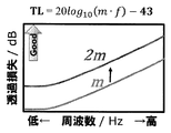
- the value of the transmission loss (TL; Transmission Loss) due to the single wall when a sound wave of a certain frequency is vertically incident on the single wall made of a homogeneous material is the frequency (f) and the surface density of the single wall. It is known that TL ⁇ 20 log 10 (m ⁇ f) ⁇ 43 [dB] is calculated using (m) (mass rule). That is, generally, the lighter the soundproof material is and the smaller the frequency of the sound wave is, the smaller the transmission loss (TL) is, and the soundproof performance is deteriorated.
- a concrete wall needs to have a size of 12 cm, and a urethane foam sound insulation material needs to have a size of more than 35 cm.
- Ni Sui et al. Applied Physics Letters 106, 171905 (2015) is an acoustic structure consisting of a lattice-shaped structure in which a latex rubber film is airtightly supported by a honeycomb made of an aramid fiber sheet having a plurality of cylindrical cells formed continuously. Metamaterials have been proposed.
- the lattice-shaped structure has a latex rubber membrane having a regular hexagonal shape (one side length is 3.65 mm) formed by a plurality of tubular cells. It is divided into compartments.
- the acoustic metamaterial as described above when applying the acoustic metamaterial as described above to a vehicle or the like, it is common to stack it on a substrate for disposing the acoustic metamaterial.
- the sound reflection performance may not be sufficiently exhibited particularly in the frequency range of 1500 to 2500 Hz depending on the application form when the acoustic metamaterial is used. ..
- the frequency range (audible range) of sounds that can be heard by a person is as wide as 20 to 20000 Hz, it is known from the theory of equal loudness curves that it is particularly sensitive to sounds around 1000 to 4000 Hz. ing. Therefore, it can be said that the improvement of the sound reflection performance in the frequency range of 1500 to 2500 Hz, which is included in the frequency range where human hearing is sensitive, occupies the most important position in the development of the sound reflection material.
- an object of the present invention is to provide a means capable of further improving the sound reflection performance in the frequency range of 1500 to 2500 Hz.
- the present inventors have conducted earnest studies in view of the above problems.
- the surface rigidity and the surface density of the sheet forming the partition are controlled so as to satisfy a predetermined relationship, and the acoustic metamaterial is arranged at a position separated from the substrate.
- the acoustic metamaterial does not have a performance (sound absorption performance) as a sound absorbing material, and may exhibit sound reflection performance by exclusively reflecting incident sound. It's known.
- a sound reflection structure including a substrate and a sound reflection material arranged on the substrate at a position separated from the substrate.
- the sound reflection material includes a sheet having elasticity and a support portion that supports the sheet and divides the sheet into partition portions.
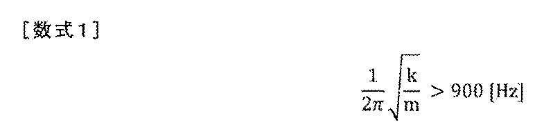
- the sound reflecting material is characterized in that the surface rigidity (k) and the surface density (m) of the sheet in the partition section satisfy the relationship of the following mathematical formula 1.
- the sound reflection performance (transmission loss) of the sound reflection material according to the present invention is determined by the sound reflection material consisting only of the lattice-shaped structure (supporting part) having the honeycomb structure, the sound reflection material consisting of only a single wall, and the sound consisting of an iron plate. It is a graph for explaining in comparison with a reflective material. It is a figure for demonstrating the sound reflection performance according to a rigidity law. A model formula assuming that both the mass law (FIG. 6) and the stiffness law (FIG. 8) are involved in the sound reflection performance of the sound reflection material according to the present invention is compared with the actual measurement value of the transmission loss. It is a graph shown.
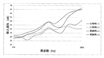
- FIG. 14 is a graph showing the results of Comparative Examples 1-1 and 1-2 and Examples 1-1 and 1-2. It is a graph which shows the result of having measured insertion loss about the sound reflection material produced in the section of the example mentioned below.
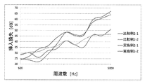
- FIG. 15 is a graph showing the results of Comparative Examples 2-1 to 2-2 and Examples 2-1 to 2-2. It is a graph which shows the result of having measured insertion loss about the sound reflection material produced in the section of the example mentioned below.
- FIG. 16 is a graph showing the results of Comparative Examples 3-1 to 3-2 and Example 3-1.
- FIG. 17 is a graph showing the results of Comparative Example 4-1 and Examples 4-1 to 4-4. It is a graph which shows the result of having measured insertion loss about the sound reflection material produced in the section of the example mentioned below.
- FIG. 18 is a graph showing the results of Examples 5-1 and 5-2.
- One embodiment of the present invention includes a substrate and a sound reflecting material arranged on the substrate, the sound reflecting material supports an elastic sheet, and partitions the sheet into partition parts. So that the surface rigidity (k) of the sheet and the surface density (m) of the sheet in the partition satisfy the relationship of the following mathematical formula 1, and the sheet is separated from the substrate. And a sound reflection structure in which the sound reflection material is arranged on the substrate.
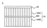
- FIG. 1 is a side view showing an appearance of a sound reflection structure according to an embodiment of the present invention.
- FIG. 2 is a perspective view showing the external appearance of the sound reflecting material that constitutes the sound reflecting structure according to the embodiment of the present invention.
- FIG. 3 is a top view of the sound reflecting material that constitutes the sound reflecting structure according to the embodiment of the present invention.
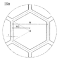
- FIG. 4 is an enlarged cross-sectional view for explaining the cross-sectional shape and the size of the support portion of the sound-reflecting material that constitutes the sound-reflecting structure according to the embodiment of the present invention.
- a sound reflection structure 1 includes a sound reflection material 10 and a substrate 20.
- a sound reflection material 10 according to an embodiment of the present invention is a lattice-shaped structure 100 (supporting portion) composed of tubular cells arranged continuously (regularly).
- a latex rubber sheet 200 made of latex rubber having elasticity.
- the latex rubber sheet 200 is airtightly joined to the lattice-shaped structure 100 so as to close one side of the openings on both sides of the lattice-shaped structure 100, and functions as a sheet-shaped base material.
- the latex rubber sheet 200 in this embodiment has a thickness of 0.25 mm (250 ⁇ m).
- the lattice structure 100 is made of polyvinyl chloride resin.
- the lattice structure 100 has a large number of cylindrical cells 110 formed continuously (regularly).
- the sound reflection material 10 is arranged on the substrate 20 so that the surface opposite to the side on which the sound reflection member 10 contacts the substrate 20.
- the sound reflection material 10 is arranged on the substrate 20 so that the latex rubber sheet 200 is separated from the substrate 20 (not in direct contact with it).
- “the sound reflecting material is arranged on the substrate” does not necessarily mean that the sound reflecting material is arranged vertically above the substrate.
- the sound reflecting material may be arranged in any direction with respect to the substrate as long as the sound reflecting material and the substrate are arranged so that the sheet constituting the sound reflecting material is separated from the substrate.
- the sound reflection material 10 may be arranged vertically below the substrate 20.
- the vibration of the sound reflecting material is less likely to be affected by the vibration of the substrate. Become.
- the sound reflecting material particularly, the elastic sheet constituting the sound reflecting material
- the sound reflection structure of the present embodiment by disposing the sound reflection material on the substrate so that the sheet is separated from the substrate, the sound reflection effect is remarkably improved as compared with the case without such a configuration.
- the mechanism is not completely clear.
- the vibrations of the sheet and the substrate forming the sound reflecting material are less likely to interfere with each other.
- the sound reflecting material in particular, the elastic sheet constituting the sound reflecting material
- the sound reflecting effect can be sufficiently exhibited.
- the soundproof effect by the closed hollow double layer is known, in the sound reflecting structure according to the present embodiment, there is not a closed space like the hollow double layer. Nevertheless, it was completely unexpected that the sound reflection structure according to the present embodiment exhibits a sound reflection performance by a sound reflection action which is superior to the soundproof effect by the hollow double layer. Further, the sound wave (reflected wave) reflected by the sound reflection structure according to the present embodiment cancels the incident wave by interfering with a part of the frequency range of the sound wave (incident wave) that is incident oppositely.
- the incident wave is muted synergistically.
- the presence of the reflected wave increases the elastic wave intensity of the atmosphere on the incident side (sound source side). Therefore, by installing an element (for example, a piezoelectric element) capable of converting elastic wave vibration into a potential on the sound source side, it is possible to convert the reflected sound wave into electric power and use it for energy regeneration.
- an element for example, a piezoelectric element
- the cross-sectional shape of the tubular cell 110 in a cross section (paper surface of FIG. 3) perpendicular to the extending direction of the lattice-shaped structure 100. Is a regular hexagon. That is, the lattice-shaped structure 100 has a so-called honeycomb structure.
- the lattice-shaped structure 100 according to the present embodiment supports the latex rubber sheet 200 as the sheet-shaped base material and divides the latex rubber sheet 200 into a plurality of (many in FIG. 2 and FIG. 3) partition portions. It is partitioned. Then, the plurality of partition portions form a regular array structure in which the plurality of partition portions having the same outer shape are regularly arrayed.
- the cell size of one cylindrical cell (110a shown in FIG. 4) constituting the honeycomb structure is 4 mm.
- the lattice-shaped structure 100 is configured by connecting a large number of cylindrical cells 110 having walls around them.
- the wall thickness of this tubular cell (distance t shown in FIG. 4) is 0.07 mm (70 ⁇ m).
- the height (distance h shown in FIG. 2) of the lattice-shaped structure (cylindrical cell) in the extending direction is 25 mm, and the lattice-shaped structure (cylindrical cell) is composed of a single structure having a uniform height.
- the sound reflection material having the structure shown in FIGS. 2 and 3 can realize excellent sound reflection performance with a very simple structure.
- the present inventors energetically studied the mechanism by which the sound reflecting material as in the above-described embodiment exhibits such excellent sound reflecting performance. As a result, the inventors have found out that a mechanism different from the soundproof material conventionally applied to vehicles and the like is involved, and completed the present invention. The finally discovered mechanism overturns the conventional wisdom regarding soundproofing materials applied to vehicles and the like.
- the mechanism by which the sound reflecting material according to the present embodiment exhibits excellent sound reflecting performance and the configuration of the present invention completed based on the mechanism clarified by the present inventors will be described step by step.
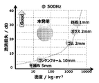
- FIG. 5 shows the sound reflection performance of the sound reflection material according to the present invention in comparison with the performance trend of the conventionally known sound insulation material.
- the conventionally known soundproof material has a performance trend that the soundproof performance (transmission loss) is improved as the density of the constituent material is increased.
- the performance trend of such a conventionally known soundproof material is known as “mass law”.
- the theoretical value (TL) of the transmission loss in the soundproofing material according to this mass rule is calculated according to the following mathematical formula 2 using the frequency (f) of the target sound wave and the surface density (m; mass per unit area) of the soundproofing material. To be done.
- the soundproof performance (transmission loss (TL)) can be improved, but on the other hand, in order to improve the soundproof performance, the surface density of the soundproof material must be increased. That was the common sense in the prior art based on the mass law (Fig. 6). In other words, it was believed that it was impossible to construct a soundproof material that exhibits high soundproof performance over a wide frequency range of 1500 to 2500 Hz from a lightweight material. On the other hand, the sound-reflecting material according to the present invention shows excellent sound-reflecting performance by being largely deviated from this performance trend (that is, showing relatively high sound-reflecting performance even at low density (light weight)). Yes (Fig. 7).
- the sound reflection performance is not exhibited at all by only the lattice-shaped structure (support portion) having the honeycomb structure. Also, in the case of a sound reflection material consisting of a single wall, sound reflection performance according to the mass law is achieved only with an elastic sheet (rubber film) (transmission loss increases in the high frequency range, but transmission loss decreases in the low frequency range). ) Is only demonstrated. Therefore, in order to exert the sound reflection performance in the low frequency range (particularly in the range of 1500 to 2500 Hz), it is necessary to use a material having a very high surface density (that is, heavy) such as an iron plate.
- the sound reflection material according to the present invention having the above-described configuration exhibits sound reflection performance in accordance with the mass law in the high frequency range, and the value of the transmission loss also decreases as the frequency decreases. ..
- the sound reflecting material according to the present invention is lightweight, it exhibits excellent sound reflecting performance even in the low frequency range (particularly in the range of 1500 to 2500 Hz) with a certain frequency (resonance frequency) as a boundary. You can
- the theoretical value (TL) of the transmission loss in the sound reflecting material that complies with the stiffness law is the frequency (f) of the target sound wave, the surface density (m; mass per unit area) of the sound reflecting material, and the surface rigidity of the sound reflecting material ( It is calculated according to the following Equation 3 using K).
- the surface rigidity (K) is approximate to a mass spring model in which one of the partition parts of the sheet partitioned by the support part (lattice-like structure) has a mass of mass m and vibrates in response to the incidence of sound waves. This is the spring constant at the time of performing, and the larger K is, the more difficult it is to deform with respect to the input.
- Equation 4 Equation 4
- the reason why not only the mass law but also the rigidity law is involved is not completely clear, but the partition portion of the elastic sheet is It is considered that the rigidity of the sheet is improved (that is, vibration is less likely to occur) due to the partitioning by the support portions (the lattice-shaped structure having the tubular cells). Therefore, the present inventors speculate that the mechanism can be well explained by the approximation by the above-mentioned mass spring model.
- the present inventors have further studied the elements necessary for designing the sound reflection characteristics of the sound reflection material.
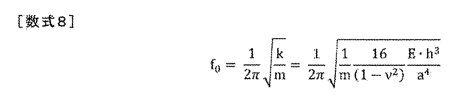
- the present inventors approximate each of the partition portions of the elastic sheet with a disk having a radius a having an equal area, and the surface rigidity (k;
- the value of surface rigidity in the case of following this approximation is represented by a small letter k), and the average deflection (w ave ) when the disk vibrates in the peripheral fixed/uniform load mode is used.
- this value of k is used in Expression 1.
- Equation 5 ⁇ is the Poisson's ratio of the sheet in the partition, E is the Young's modulus [Pa] of the sheet in the partition, and h is the film thickness [m] of the sheet in the partition.
- the radius a when the partition is approximated to a disk is the area equivalent circular radius [m] of the partition.
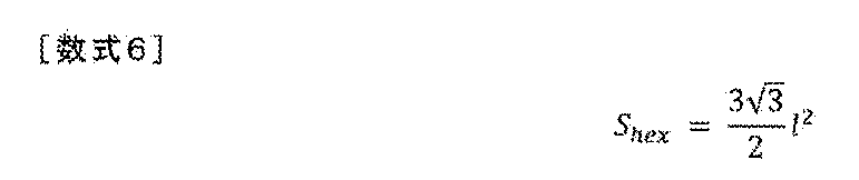
- the partition portion is a hexagon with one side having a length of l (ell)
- the area S hex of the partition portion (hexagon) is calculated as in Equation 6 below.
- sheet areal density (m) in the compartment can be expressed as in the following mathematical formula 9.
- ⁇ is the density of the sheet in the partition section [kg/m 3 ] and h is the thickness of the sheet in the partition section [m].
- the value of the resonance frequency (f 0 ) is the value of the density ( ⁇ ; mass per unit volume; kg/m 3 ) of the sheet in the partition and the value in the partition described above.
- the value of the film thickness [m] of the sheet it can be expressed as the following Expression 10. This means that the value of the resonance frequency (f 0 ) indicated by the sound reflecting material can be controlled by variously changing the size and shape of the partition, the material and the film thickness of the sheet in the partition.
- the problem to be solved by the present invention is to provide means capable of exhibiting even higher sound reflection performance in the frequency range of 1500 to 2500 Hz. Then, as shown in FIGS. 8 and 9, with the resonance frequency (f 0 ) as a boundary, as the frequency becomes smaller, the sound reflection performance (value of transmission loss) according to the rigidity law becomes more excellent. Therefore, the present inventors considered that the sound reflection performance for sounds in the frequency range of 2500 Hz or lower could be improved by setting the resonance frequency (f 0 ) to a value above a certain level.
- the size and shape of the partitioning portion By changing the material and film thickness of the sheet in the partition section, a large number of sound reflection materials having different resonance frequencies (f 0 ) were produced, and the sound reflection performance of each of them (particularly in the frequency range of 1500 to 2500 Hz) was evaluated.
- the sheet surface rigidity (k; calculated by the above formula 5) and the sheet surface density (m; calculated by the above formula 9) in the above-mentioned partition satisfy the relationship of the following formula 1, In particular, it was confirmed that excellent sound reflection performance can be exhibited even in a frequency range of 2500 Hz or less.
- Formula 1 below means that the resonance frequency (f 0 ) calculated based on the above-mentioned approximation is greater than 900 [Hz].
- the form of the value on the left side in Expression 1 is not particularly limited, and can be set as appropriate according to the frequency region in which the sound reflecting material is desired to exhibit sound reflecting performance.
- the resonance frequency shifts to the higher frequency side as the value on the left side of Expression 1 increases, and therefore the resonance frequency may be appropriately set in consideration of this.
- the value on the left side of Formula 1 is preferably 1400 Hz or higher, more preferably 2000 Hz or higher, even more preferably 3000 Hz or higher, even more preferably 4000 Hz or higher, and particularly preferably 5000 Hz or higher.
- the value on the left side in Expression 1 is, for example, 10000 Hz or higher, for example, 50000 Hz or higher, and for example, 100000 Hz or higher.
- the upper limit value of the value on the left side of Formula 1 is preferably 1,000,000 Hz or less, and more preferably 800,000 Hz or less. , And more preferably 600,000 Hz or less.
- the sheet having elasticity and the surface rigidity and the surface density of the sheet constituting the partition of the sound reflection material are controlled so as to satisfy a predetermined relationship.
- the sound reflection structure according to the present invention preferably has a maximum insertion loss curve for white noise in the frequency range of 1500 to 2500 [Hz]. Further, the maximum value of the insertion loss curve at this time is more preferably 45 [dB] or more, and further preferably 50 [dB] or more.
- Non-Patent Document 1 As a result of the cell size being too large, the surface rigidity of the elastic sheet becomes small, and the value of (k/m) 1/2 /2 ⁇ does not become 900 Hz or more. Therefore, it is considered that excellent sound reflection performance cannot be exhibited particularly in the frequency range of 2500 Hz or less.
- a resin structure including a core layer formed by arranging a plurality of cells in parallel and skin layers arranged on both surfaces of the core layer has been proposed for various applications, and the resin structure absorbs sound. It has also been attempted to provide sound and sound insulation.
- the conventional technique intended to give such a resin structure a sound absorbing property or a sound insulating property is based on the premise that the skin layer is provided with a communication hole for communicating the inside and outside of the cells constituting the core layer. There is. Even when the skin layer is provided with the communication holes as described above, the surface rigidity of the elastic sheet cannot be sufficiently secured.
- the value of (k/m) 1/2 /2 ⁇ does not exceed 900 Hz, so that excellent sound reflection performance cannot be exhibited particularly in the frequency range of 2500 Hz or less.
- the resin structure having the same structure as above there have been conventionally proposed techniques which are not premised on providing the above-mentioned communicating holes in the skin layer, but these techniques are not related to sound reflection or the like. .. Some of these technologies are intended to be applied to applications requiring rigidity of containers, shelves, pallets, panels, etc. for the purpose of improving mechanical strength such as bending rigidity and bending strength. .. Further, in another proposal using the same resin structure, the skin layer is required to contain an impact resistance improving material for lowering the elastic modulus of the skin layer.
- a metal member having a thickness of about 0.05 to several mm is arranged as a skin layer, and a material having high rigidity is also used for the skin layer. .. Therefore, in the related art relating to the resin structure in which the communication holes are not provided in the skin layer, the value of the surface rigidity in the present invention becomes too large, so that the value of (k/m) 1/2 /2 ⁇ cannot be measured. It is considered that the value becomes large (on the high frequency side).
- the constituent material of the elastic sheet (corresponding to the latex rubber sheet 200 shown in FIGS. 1 and 2) is not particularly limited, and various materials can be used as long as they are elastic materials.
- the term “having elasticity” means that the sheet is made of a material having a Young's modulus value in the range of 0.001 to 70 [GPa].
- the value of the Young's modulus of the resin can be measured according to JIS K7161-1 (2014).
- the Young's modulus of metal can be measured according to JIS Z2241 (2011).
- the Young's modulus of rubber can be measured according to JIS Z6251 (2010).
- chloroprene rubber CR
- SBR styrene/butadiene rubber
- EPDM ethylene/propylene/diene rubber
- a rubber material such as rubber (NBR) may be used as well.
- a resin material, a metal material, a paper material, or the like may be used as the elastic sheet.
- a material having a cushioning function such as an air cushion can also be used. All of these materials, including rubber materials, have high elasticity to the extent that the effects of the sound reflecting material according to the present embodiment can be exhibited.
- the resin material examples include polyethylene (for example, low-density polyethylene, high-density polyethylene, etc.), polyolefin resin such as polypropylene, polyvinyl chloride resin, acrylic resin, methacrylic resin, acrylonitrile-butadiene-styrene resin, vinyl acetate resin, ethylene-acetic acid. Examples include vinyl resins and styrene-butadiene resins.
- thermosetting resin silicone resin, urethane resin, melamine resin, thermosetting acrylic resin, urea resin, phenol resin, resorcin resin, alkylresorcin resin, epoxy resin, thermosetting polyester, etc. may be used.
- urethane resin prepolymers urethane resin prepolymers, urea resin prepolymers (initial condensation products), phenol resin prepolymers (initial condensation products), diallyl phthalate prepolymers, acrylic oligomers, polyvalent isocyanates, methacrylic ester monomers, which produce these resins, Prepolymers such as diallyl phthalate monomers, oligomers, resin precursors such as monomers may be used.
- the metal material include copper and aluminum.
- the constituent material of the elastic sheet is not limited to the above, and other materials may of course be used. A rubber material is preferable as the constituent material of the elastic sheet, and latex rubber or EPDM rubber is more preferable.
- these rubber materials are particularly preferable materials because they are lightweight, and particularly when considering application to vehicles, they greatly contribute to fuel efficiency reduction.
- polyolefin resin such as polypropylene is also preferable as a constituent material of the elastic sheet.
- the thickness of the elastic sheet is preferably 10 to 1000 ⁇ m, more preferably 100 to 500 ⁇ m from the viewpoint of the sound reflection effect of the sound reflection material.
- the support part supports the above-mentioned elastic sheet and partitions the sheet into partition parts (airtightly partitioned).
- FIGS. 1 to 3 are described as having a large number of compartments, even if there is only one compartment, it is within the scope of the present invention.
- the constituent material of the supporting portion is not particularly limited, and conventionally known thermoplastic resins or thermosetting resins can be used in addition to the polyvinyl chloride resin used in the above-described embodiment. Further, a metal material or another material may be used as a constituent material of the support portion. Each of these materials has physical properties suitable for holding an elastic sheet and partitioning it into compartments.
- thermoplastic resin in addition to polyvinyl chloride resin, polyethylene (for example, low-density polyethylene, high-density polyethylene, etc.), polyolefin resin such as polypropylene, acrylic resin, methacrylic resin, acrylonitrile-butadiene-styrene resin, vinyl acetate resin, Examples thereof include ethylene-vinyl acetate resin and styrene-butadiene resin.
- thermosetting resin urethane resin, melamine resin, thermosetting acrylic resin, urea resin, phenol resin, resorcin resin, alkylresorcin resin, epoxy resin, thermosetting polyester, etc. may be used.
- urethane resin prepolymers urethane resin prepolymers, urea resin prepolymers (initial condensation products), phenol resin prepolymers (initial condensation products), diallyl phthalate prepolymers, acrylic oligomers, polyvalent isocyanates, methacrylic ester monomers, which produce these resins, Prepolymers such as diallyl phthalate monomers, oligomers, resin precursors such as monomers may be used.
- a thermoplastic resin is preferably used from the viewpoint of easy molding, and a vinyl chloride resin and a polyolefin resin are particularly preferable because they are lightweight, excellent in durability and inexpensive.
- the support portion is preferably a lattice-shaped structure having a large number of continuously formed cylindrical cells.
- the support section partitions the elastic sheet into a plurality of partition sections.
- at least a part of the plurality of partition sections constitutes a regular array structure in which a plurality of partition sections having the same outer shape are regularly arrayed.
- At least one lattice-shaped structure (support portion) for one sheet may be divided into a plurality of members.
- the sound reflecting material according to the present embodiment has flexibility as a whole.
- the support portion is not divided into a plurality of members, it is a preferable embodiment that the sound reflection material has flexibility as a whole.
- the flexibility of the sound reflecting material as described above is preferable because it is possible to arrange the sound reflecting material in a manner to follow sound sources of various shapes.
- the outer shape of the partition part in the above-described regular array structure is not limited to the regular hexagon as shown in FIGS. 2 to 4, Other shapes may be used. If a large number of cylindrical cells are arranged by continuously forming regular polygons having the same cross-sectional shape, regular hexagons, regular squares (squares), and regular triangles can be adopted as the cross-sectional shape. .. By adopting these shapes, it is possible to provide a support that is easy to manufacture and exhibits excellent strength.
- the cross-section of the lattice-like structure is a pattern in which a plurality of regular polygons are regularly arranged, for example, by Archimedes' plane filling method (four regular triangles, one regular hexagon), ( 3 regular triangles, 2 regular squares (square) x 2 ways (1 regular triangle, 2 regular squares, 1 regular hexagon), (2 regular triangles, 2 regular hexagons), (One regular triangle, two regular dodecagons), (one regular square (square), one regular hexagon, one regular dodecagon), (one regular square (square), two regular octagons) Any combination can be configured so that the cross section of the lattice structure has the above pattern.
- the cross-sectional shape of the tubular cell is a regular hexagon (that is, the lattice-shaped structure has a honeycomb structure. Most preferably).
- the size of the tubular cells forming the lattice-like structure there is no particular limitation on the specific value as long as it satisfies the above-mentioned mathematical formula 1.
- the size of the tubular cell is 6. It is preferably 0 mm or less. By having such a size, excellent sound reflection performance can be exhibited.
- the size of the tubular cell is 5.9 mm or less, 5.8 mm or less, 5.7 mm or less, 5.6 mm or less, 5.5 mm or less, 5 0.4 mm or less, 5.3 mm or less, 5.2 mm or less, 5.1 mm or less, 5.0 mm or less, 4.9 mm or less, 4.8 mm or less, 4.7 mm or less, 4.6 mm or less, 4.5 mm or less, 4 It may be less than or equal to 4.4 mm, less than or equal to 4.3 mm, less than or equal to 4.2 mm, less than or equal to 4.1 mm, less than or equal to 4.0 mm, and the narrower the numerical value range, the more preferable.
- the size of the tubular cell there is no particular limitation on the lower limit of the size of the tubular cell, but if the size of the tubular cell is too small, the mass of the lattice-like structure (and by extension the sound reflecting material) increases, so it is 2.0 mm or more. It is preferable.
- the thickness of the wall of the tubular cell (distance t shown in FIG. 4) is preferably 10 to 150 ⁇ m, more preferably 30 to 100 ⁇ m.
- the lattice-like structure (supporting portion) is provided only on one side of the elastic sheet.
- the lattice-shaped structures (first lattice-shaped structure (first supporting portion) 100A and second lattice-shaped structure (second supporting portion) 100B) provided on both surfaces of the elastic sheet, respectively.
- the forms may be the same as or different from each other.
- a lattice-like structure (first lattice-like structure 100A (first support portion) and second lattice-like structure (second support portion) 100B) provided on both surfaces of the elastic sheet, respectively.
- the forms are preferably different from each other.
- the shape of the tubular cells of the lattice-shaped structure (the first lattice-shaped structure 100A (first support portion) and the second lattice-shaped structure (second support portion) 100B) is elastic. It is more preferable to arrange the respective lattice-like structures so that they are exactly overlapped on both sides of the sheet having. With such a configuration, there is an advantage that particularly excellent sound reflection performance can be exhibited.
- the first support portion and the second support portion may have substantially the same thickness.
- the thickness of one of the first support portion and the second support portion may be 19/20 to 20/19 times the thickness of the other.
- the thickness of each of the first support portion and the second support portion may be substantially different.
- the thickness of one of the first support and the second support can be more than 20/19 times the thickness of the other.
- the constituent material of the supporting portion is not particularly limited, the constituent materials of the first supporting portion and the second supporting portion may be the same as each other or different from each other. Good. By selecting the constituent materials of the first support portion and the second support portion in this manner, it is possible to precisely control the target frequency range exhibiting the sound reflection effect.
- the lattice-shaped structure (support portion) in the extending direction is larger, particularly excellent sound reflection performance tends to be exhibited over a wide range of low frequency range of 2000 Hz or less. From this point of view, it is preferable that the lattice-shaped structure (support portion) is a single structure having a uniform height. Further, in this case, the height of the lattice-shaped structure in the extending direction (distance h shown in FIG. 2) is preferably 5 mm or more, more preferably 6 mm or more, further preferably 13 mm or more, It is more preferably 19 mm or more, particularly preferably 22 mm or more, and most preferably 25 mm or more.
- the sound reflecting material according to this embodiment is preferably lightweight.
- the surface density of the whole of the sound reflective material according to the present embodiment is preferably less than 3.24kg / m 2, more preferably not more than 2.0 kg / m 2, more preferably 1.5kg /M 2 or less, particularly preferably 1.0 kg/m 2 or less.
- the sound reflection material according to the present embodiment does not have the performance (sound absorption performance) as the sound absorption material, and the sound reflection performance is obtained by exclusively reflecting the incident sound. It is also known to be exerting. This will be described in detail with reference to FIGS. 12 and 13 in the section of Examples described later.
- the sound-reflecting material according to the present embodiment can be suitably used for shielding noise from various sound sources by forming a sound-reflecting structure on a substrate.
- a metal plate iron plate, aluminum plate, etc.
- resin plate that is basically impermeable to air
- the thickness of the substrate is preferably 0.5 to 2.0 mm in the case of a metal plate, and 0.5 to 20 mm in the case of a resin plate.
- the sound-reflecting material according to the present embodiment and the sound-reflecting structure using the sound-reflecting material can be made extremely lightweight. Since the sound reflecting material and the sound reflecting structure according to the present embodiment can be reduced in weight as described above, it is preferable to be mounted on a vehicle and used. In particular, it is most preferably applied to a sound reflection application for noise generated from a portion (inherent sound source) that generates a large sound such as an engine, a transmission, and a drive system.
- the application site in the engine compartment, it can be applied to an engine head cover, an engine body cover, a hood insulator, a dash front insulator, an air box partition, an air intake air cleaner, a dust side duct, an under cover, and the like.
- It can be applied to trim, parcel panel, seat headrest, front seat seat back, rear seat seat back, etc.
- the trunk it can be applied to a trim of a trunk floor, a trunk board, a trim of a trunk side, a sound reflector in the trim, a drafter cover, and the like.
- the invention can be applied to the inside of a frame of a vehicle or between panels, for example, to trims of pillars and fenders.
- each member outside the vehicle for example, an under cover under the floor, a fender protector, a back door, a wheel cover, and an aerodynamic cover for a suspension. Therefore, as the substrate forming the sound reflection structure, the metal plate, the resin plate, or the like as the constituent material of the above-described various application portions can be used as it is.
- the supporting portion has an opening cross section on the side opposite to the elastic sheet, and the opening cross section of the supporting portion contacts the substrate.
- a sound reflection material is arranged on the substrate. Further, at this time, it is more preferable that the opening cross section of the supporting portion is arranged on the substrate in a state not being bonded to the substrate. With such a configuration, the sound reflection performance in the frequency range of 1500 to 2500 Hz can be further improved.
- the sound reflection structure according to this embodiment is arranged with respect to the sound source.
- the sound source is arranged in the extending direction of the tubular cells forming the lattice-shaped structure (support portion).
- the elastic sheet forming the sound reflecting material may be arranged so as to be located on the sound source side, or the opening of the cylindrical cell forming the sound reflecting material may be the sound source.
- the former arrangement form is more preferable from the viewpoint of more excellent sound reflection performance.
- the sound reflection structure was arranged so that the substrate (iron plate) was located on the side opposite to the microphone, and the evaluation was performed.
- the sound source generation conditions were as follows: Spectral level: White noise (100-8192Hz) F max : 8192 Hz Average value: 300 times addition average (measurement was performed 300 times while shifting the time little by little in one measurement, and the addition average was taken as the measurement value) Overlap: 75%.
- Production Example 2 A sound reflecting material of this Production Example was produced in the same manner as in Production Example 1 described above except that the thickness of the honeycomb structure (support) was set to 12.5 mm.
- Production Example 3 A sound reflecting material of this Production Example was produced in the same manner as in Production Example 1 described above except that the thickness of the honeycomb structure (support) was set to 6 mm.
- Production Example 5 This Production Example was performed in the same manner as Production Example 4 described above except that the thickness of the honeycomb structure (support) arranged on each surface of the elastic sheet (sheet made of latex rubber) was 6 mm. The sound reflection material was manufactured.
- Table 1 shows the specifications of the sound reflecting material produced in each of the above production examples.
- the normal incident sound absorption coefficient for the incident sound in the frequency range of 400 to 5000 Hz was measured in accordance with the "reverberation room sound absorption coefficient measurement method" defined in JIS A1409. .
- the sound transmission loss was measured by measuring the sound intensity of a similar incident sound with a method combining a reverberation room and an anechoic room.
- a sample (sound reflecting material) is set in the opening between the reverberation room and the anechoic room.
- an incident sound is generated from the speaker in the reverberation room, and the average sound pressure level in the reverberation room is measured as the power of the sound source side incident on the sample (sound reflecting material).
- the sound receiving side measures the divided measurement surface using an intensity probe set near the sample (sound reflector) in the anechoic chamber, and estimates the power transmitted from the sample.
- the sound transmission loss is calculated from the incident power and the transmission power thus obtained, and the area of the sample (sound reflecting material).
- the relationship between the sound transmission loss and each measured value is expressed by the following equation.
- TL SPL 0 ⁇ PWL i +10logS ⁇ 6
- TL is the sound transmission loss [dB]
- SPL 0 is the average sound pressure level [dB] in the reverberation room
- PWL i is the power level [dB] of the transmitted sound
- S is the sample (sound reflection).
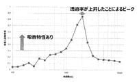
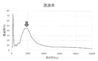
- the sound absorption measurement result is shown in FIG. 12, and the transmission measurement result is shown in FIG.
- the graph showing the measurement results of the sound absorption coefficient shown in FIG. 12 it is generally interpreted that the sound absorption performance is exhibited in the frequency range where the vertical axis (normal incident sound absorption coefficient) is 0.3 or more.
- the transmittance shown in FIG. 13 it is found that the transmittance is increased in the frequency range of 1000 to 3000 Hz where the peak occurs in FIG.
- the incident sound may be reflected, absorbed, disappeared, or transmitted.
- the sound reflecting material according to the present invention does not have the performance (sound absorbing performance) as the sound absorbing material, and exhibits the sound reflecting performance by exclusively reflecting the incident sound.
- Example 1-1 Other than disposing the sound reflecting material and the iron plate so that the sheet forming the sound reflecting material is located on the side opposite to the iron plate (that is, the opening cross section of the supporting portion forming the sound reflecting material is adjacent to the iron plate) In the same manner as in Comparative Example 1-2 described above, the sound reflection structure of this example was manufactured.
- Example 1-2 A sound reflecting structure of this example was manufactured in the same manner as in Example 1-1 described above except that the sound reflecting material manufactured in Manufacturing Example 4 was used. At this time, the sound reflecting material and the iron plate were arranged so that one opening cross section of the supporting portion constituting the sound reflecting material was adjacent to the iron plate.
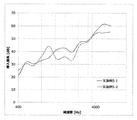
- FIG. 14 shows the insertion loss results obtained by evaluating the sound reflection performance of the above-mentioned examples and comparative examples.
- the sound-reflecting structure according to the present invention has elasticity even if the sound-reflecting structure including only the substrate (iron plate) or the sound-reflecting material having the same structure as the present invention is used. Compared to the sound reflection structure in which the sheet is in direct contact with the substrate (iron plate), it exhibits excellent sound reflection performance.
- Example 2-1 Other than disposing the sound reflecting material and the iron plate so that the sheet forming the sound reflecting material is located on the side opposite to the iron plate (that is, the opening cross section of the supporting portion forming the sound reflecting material is adjacent to the iron plate) In the same manner as in Comparative Example 2-2 described above, the sound reflection structure of this example was manufactured.
- Example 2-2 A sound reflecting structure of this example was manufactured in the same manner as in Example 1-1 described above except that the sound reflecting material manufactured in Manufacturing Example 5 was used. At this time, the sound reflecting material and the iron plate were arranged so that one opening cross section of the supporting portion constituting the sound reflecting material was adjacent to the iron plate.
- FIG. 15 shows the results of insertion loss obtained by evaluating the sound reflection performance of the above Examples and Comparative Examples.
- the sound-reflecting structure according to the present embodiment is a sound-reflecting structure including only the substrate (iron plate) even when the thickness of the support that constitutes the sound-reflecting material is different. Even when a sound reflecting material having the same structure as that of the present invention is used, it exhibits excellent sound reflecting performance as compared with a sound reflecting structure in which an elastic sheet is in direct contact with a substrate (iron plate).
- Example 3-1 Other than disposing the sound reflecting material and the iron plate so that the sheet forming the sound reflecting material is located on the side opposite to the iron plate (that is, the opening cross section of the supporting portion forming the sound reflecting material is adjacent to the iron plate) In the same manner as in Comparative Example 3-2 described above, the sound reflection structure of this example was manufactured.
- FIG. 16 shows the results of the insertion loss obtained by evaluating the sound reflection performance of the above-mentioned examples and comparative examples.
- the sound-reflecting structure according to the present embodiment is a sound-reflecting structure including only the substrate (iron plate) even when the thickness of the support that constitutes the sound-reflecting material is different. Even when a sound reflecting material having the same structure as that of the present invention is used, it exhibits excellent sound reflecting performance as compared with a sound reflecting structure in which an elastic sheet is in direct contact with a substrate (iron plate).
- Example 4-1 The sound-reflecting structure manufactured in Example 1-2 (the sound-reflecting material manufactured in Manufacturing Example 4 laminated on an iron plate) was directly used as the sound-reflecting structure of this example.
- Example 4-2 The sound-reflecting structure manufactured in Example 2-2 (the sound-reflecting material manufactured in Manufacturing Example 5 laminated on an iron plate) was directly used as the sound-reflecting structure of this example.
- Example 4-3 A sound reflecting structure of this example was manufactured in the same manner as in Example 4-1 described above, except that the sound reflecting material manufactured in Manufacturing Example 6 was used. At this time, among the supporting parts constituting the sound reflecting material, the sound reflecting material and the iron plate were arranged such that the opening cross section of the supporting part having a thickness of 12.5 mm was adjacent to the iron plate.
- Example 4-4 Among the supporting parts constituting the sound reflecting material, the sound reflecting material and the iron plate are arranged in such a manner that the opening cross section of the supporting part having a thickness of 6 mm is adjacent to the iron plate. Thus, the sound reflection structure of this example was manufactured.
- FIG. 17 shows the results of the insertion loss obtained by evaluating the sound reflection performance of the above Examples and Comparative Examples.
- the sound-reflecting structure according to the present embodiment is a case where the supporting portions of the sound-reflecting material constituting the sound-reflecting structure are arranged on both sides of the elastic sheet, respectively. Also shows excellent sound reflection performance as compared with the sound reflection structure composed of only the substrate (iron plate) and the sound reflection structure described in each of the comparative examples.
- Example 5-1 The sound-reflecting structure manufactured in Example 1-1 (the sound-reflecting material manufactured in Manufacturing Example 1 laminated with an iron plate) was directly used as the sound-reflecting structure of this example.
- Example 5-2 Adhesive is applied to the opening cross section of the supporting portion that constitutes the sound reflecting material, and the sound reflecting material and the iron plate are arranged so that the opening cross section coated with the adhesive is adjacent to the iron plate.
- a sound reflection structure of this example was produced in the same manner as in Example 5-1 described above except that and were bonded together with an adhesive.
- FIG. 18 shows the result of insertion loss obtained by evaluating the sound reflection performance of the above example.
- the sound reflection performance is further improved particularly in the frequency range of 1500 to 2500 Hz by disposing the sound reflection material on the substrate in a state where the opening cross section of the supporting portion is not adhered to the substrate. To do.
- 1 sound reflection structure 10 sound reflectors, 20 substrates, 100 grid-like structure (support), 100A 1st lattice-like structure (1st support part), 100B second lattice-shaped structure (second support portion), 110, 110a tubular cell, 200 latex rubber sheet (elastic sheet), h Height in the extending direction of the support (cylindrical cell), w Size of cylindrical cell (distance between parallel sides facing each other in regular hexagon of cross section), a Length of one side of a regular hexagon, which is the cross-sectional shape of the tubular cell, t Thickness of the inner wall (lattice wall) of the tubular cell.
Landscapes
- Physics & Mathematics (AREA)
- Engineering & Computer Science (AREA)
- Acoustics & Sound (AREA)
- Multimedia (AREA)
- Soundproofing, Sound Blocking, And Sound Damping (AREA)
- Building Environments (AREA)
- Vehicle Interior And Exterior Ornaments, Soundproofing, And Insulation (AREA)
Abstract
Description








弾性を有するシート(図1および図2に示すラテックスゴムシート200に相当)の構成材料について特に制限はなく、弾性を有する材料であれば種々の材料が用いられうる。本明細書において、シートが「弾性を有する」とは、ヤング率の値が0.001~70[GPa]の範囲内の値である材料から構成されていることを意味する。なお、ヤング率の値は、樹脂についてはJIS K7161−1(2014年)により測定されうる。また、金属のヤング率についてはJIS Z2241(2011年)により測定されうる。そして、ゴムのヤング率についてはJIS Z6251(2010年)により測定されうる。弾性を有するシートの構成材料としては、上述した実施形態において用いられているラテックスゴムのほか、クロロプレンゴム(CR)、スチレン・ブタジエンゴム(SBR)、エチレン・プロピレン・ジエンゴム(EPDM)、アクリロニトリル・ブタジエンゴム(NBR)などのゴム材料が同様に用いられうる。また、樹脂材料や金属材料、紙材料などが弾性を有するシートとして用いられてもよい。さらに、エアークッションなどの緩衝機能を有する材料もまた、用いられうる。これらの材料はいずれも、ゴム材料も含め、本形態に係る音反射材の効果を発現できる程度に高い弾性を有するものである。樹脂材料としては、ポリエチレン(例えば、低密度ポリエチレン、高密度ポリエチレンなど)、ポリプロピレン等のポリオレフィン樹脂、ポリ塩化ビニル樹脂、アクリル樹脂、メタクリル樹脂、アクリロニトリル−ブタジエン−スチレン樹脂、酢酸ビニル樹脂、エチレン−酢酸ビニル樹脂、スチレン−ブタジエン樹脂等が例示される。また、熱硬化性樹脂としては、シリコーン樹脂、ウレタン樹脂、メラミン樹脂、熱硬化型アクリル樹脂、尿素樹脂、フェノール樹脂、レゾルシン樹脂、アルキルレゾルシン樹脂、エポキシ樹脂、熱硬化型ポリエステル等が用いられうる。なお、これらの樹脂を生成するウレタン樹脂プレポリマー、尿素樹脂プレポリマー(初期縮合体)、フェノール樹脂プレポリマー(初期縮合体)、ジアリルフタレートプレポリマー、アクリルオリゴマー、多価イソシアナート、メタクリルエステルモノマー、ジアリルフタレートモノマー等のプレポリマー、オリゴマー、モノマー等の樹脂前駆体が用いられてもよい。金属材料としては、銅、アルミニウムなどが挙げられる。弾性を有するシートの構成材料は上記のものに限定されず、その他の材料が用いられてももちろんよい。なお、弾性を有するシートの構成材料としてはゴム材料が好ましく、なかでもラテックスゴムまたはEPDMゴムがより好ましい。これらのゴム材料を弾性を有するシートの構成材料として用いることで、本発明に係る音反射材による音反射効果が好適に発現しうる。また、これらのゴム材料は軽量であるという点で、特に車両用途への適用を考慮すると、低燃費化への寄与も大きいため、特に好ましい材料であると言える。さらに、低コスト化の観点からは、ポリプロピレン等のポリオレフィン樹脂もまた、弾性を有するシートの構成材料として好ましいものである。
支持部は、上述した弾性を有するシートを支持するとともに当該シートを(気密的に区画された)区画部に区画するものである。このような機能を発現可能な構成を有するものであれば、支持部の具体的な構成について特に制限はない。図1~図3は多数の区画部が存在するように記載されているが、区画部は1つのみであっても本発明の範囲内のものである。
後述する実施例および比較例で作製した音反射構造体について、各周波数の音波に対する音反射性能を測定した。具体的には、図11に示すような鉄壺からなる遮音ボックスの内部にスピーカー(音源)を配置し、遮音ボックスの開口部にサンプル(音反射構造体)を配置した。また、遮音ボックスの開口部におけるサンプル(音反射構造体)の周囲からの音漏れを防止するために、サンプル(音反射構造体)の周囲にゴムシートを配置した。そして、遮音ボックスの内部に設置したスピーカー(音源)から音を発生させて、サンプル(音反射構造体)を配置しない場合(コントロール)に対する挿入損失[単位:dB]を測定することにより、音反射性能を評価した。ある周波数における挿入損失の値が大きいほど、当該周波数の音波に対する音反射性能に優れることを意味する。なお、以下の実施例および比較例の欄において特記しない限り、基板(鉄板)がマイクとは反対の側に位置するように音反射構造体を配置して評価を行った。また、音源の発生条件は以下のとおりとした:
スペクトルレベル:ホワイトノイズ(100~8192Hz)
Fmax:8192Hz
平均値:300回の加算平均(1回の測定において時間を少しずつずらしながら300回の測定を行い、その加算平均を測定値とした)
オーバーラップ:75%。
[製造例1]
弾性を有するシート(ラテックスゴムからなるシート;膜厚0.25mm)と、ポリ塩化ビニル(PVC)からなるハニカム構造体(多数の正六角形断面を有するハニカム支持体)(支持体厚さ25mm)とを準備した。ここで、ハニカム構造体を構成する筒状セルのサイズ(ハニカム構造体の断面形状の正六角形における対向する平行な辺の距離;図4に示す距離W)を4mmとした。次いで、上記シートの一方の面に、上記ハニカム構造体の開口断面を気密的に接着して、図2に示す構造を有する音反射材を作製した。
ハニカム構造体(支持体)の厚さを12.5mmとしたこと以外は、上述した製造例1と同様にして、本製造例の音反射材を作製した。
ハニカム構造体(支持体)の厚さを6mmとしたこと以外は、上述した製造例1と同様にして、本製造例の音反射材を作製した。
厚さがともに12.5mmのPVC製ハニカム構造体(セルサイズ4mm)を、弾性を有するシート(ラテックスゴムからなるシート)の両面に配置(接着)したこと以外は、上述した製造例1と同様にして、本製造例の音反射材を作製した。
弾性を有するシート(ラテックスゴムからなるシート)の各面に配置されるハニカム構造体(支持体)の厚さをともに6mmとしたこと以外は、上述した製造例4と同様にして、本製造例の音反射材を作製した。
弾性を有するシート(ラテックスゴムからなるシート)の各面に配置されるハニカム構造体(支持体)について、一方の厚さを6mmとし、他方の厚さを12.5mmとしたこと以外は、上述した製造例4と同様にして、本製造例の音反射材を作製した。
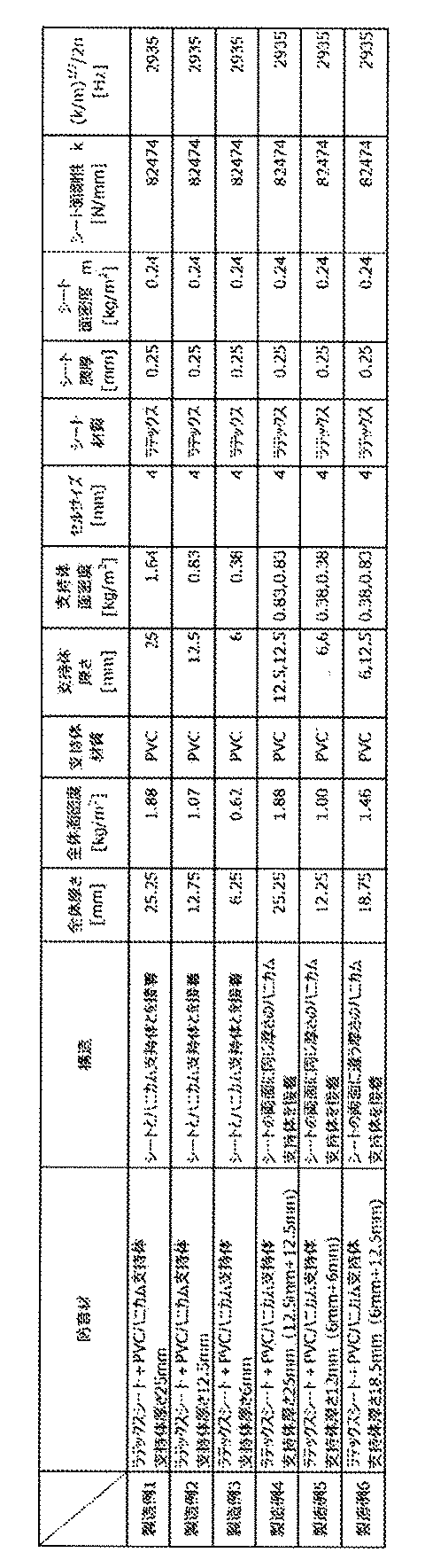
上記製造例1で作製した音反射材について、吸音特性の有無を評価した。
式中、TLは音響透過損失[dB]であり、SPL0は残響室内の平均音圧レベル[dB]であり、PWLiは透過音のパワーレベル[dB]であり、Sは試料(音反射材)の面積[m2]である。
[比較例1−1]
鉄板(厚さ1mm)を、そのまま本比較例の防音構造体とした。
上記製造例1で作製した音反射材を、鉄板(厚さ1mm)と積層して、本比較例の音反射構造体を作製した。この際、音反射材を構成するシートが鉄板に隣接するように音反射材および鉄板を配置した。
音反射材を構成するシートが鉄板とは反対側に位置するように(すなわち、音反射材を構成する支持部の開口断面が鉄板に隣接するように)音反射材および鉄板を配置したこと以外は、上述した比較例1−2と同様にして、本実施例の音反射構造体を作製した。
音反射材として、上記製造例4で作製したものを用いたこと以外は、上述した実施例1−1と同様にして、本実施例の音反射構造体を作製した。この際、音反射材を構成する支持部の一方の開口断面が鉄板に隣接するように音反射材および鉄板を配置した。
鉄板(厚さ1mm)を、そのまま本比較例の防音構造体とした。
上記製造例2で作製した音反射材を、鉄板(厚さ1mm)と積層して、本比較例の音反射構造体を作製した。この際、音反射材を構成するシートが鉄板に隣接するように音反射材および鉄板を配置した。
音反射材を構成するシートが鉄板とは反対側に位置するように(すなわち、音反射材を構成する支持部の開口断面が鉄板に隣接するように)音反射材および鉄板を配置したこと以外は、上述した比較例2−2と同様にして、本実施例の音反射構造体を作製した。
音反射材として、上記製造例5で作製したものを用いたこと以外は、上述した実施例1−1と同様にして、本実施例の音反射構造体を作製した。この際、音反射材を構成する支持部の一方の開口断面が鉄板に隣接するように音反射材および鉄板を配置した。
鉄板(厚さ1mm)を、そのまま本比較例の防音構造体とした。
上記製造例3で作製した音反射材を、鉄板(厚さ1mm)と積層して、本比較例の音反射構造体を作製した。この際、音反射材を構成するシートが鉄板に隣接するように音反射材および鉄板を配置した。
音反射材を構成するシートが鉄板とは反対側に位置するように(すなわち、音反射材を構成する支持部の開口断面が鉄板に隣接するように)音反射材および鉄板を配置したこと以外は、上述した比較例3−2と同様にして、本実施例の音反射構造体を作製した。
鉄板(厚さ1mm)を、そのまま本比較例の防音構造体とした。
実施例1−2で作製した音反射構造体(製造例4で作製した音反射材を鉄板と積層したもの)を、そのまま本実施例の音反射構造体とした。
実施例2−2で作製した音反射構造体(製造例5で作製した音反射材を鉄板と積層したもの)を、そのまま本実施例の音反射構造体とした。
音反射材として、上記製造例6で作製したものを用いたこと以外は、上述した実施例4−1と同様にして、本実施例の音反射構造体を作製した。この際、音反射材を構成する支持部のうち、厚さが12.5mmの支持部の開口断面が鉄板に隣接するように音反射材および鉄板を配置した。
音反射材を構成する支持部のうち、厚さが6mmの支持部の開口断面が鉄板に隣接するように音反射材および鉄板を配置したこと以外は、上述した実施例4−2と同様にして、本実施例の音反射構造体を作製した。
実施例1−1で作製した音反射構造体(製造例1で作製した音反射材を鉄板と積層したもの)を、そのまま本実施例の音反射構造体とした。
音反射材を構成する支持部の開口断面に接着剤を塗布し、接着剤を塗布された開口断面が鉄板に隣接するように音反射材および鉄板を配置して、支持部の開口断面と鉄板とを接着剤により接着させたこと以外は、上述した実施例5−1と同様にして、本実施例の音反射構造体を作製した。
10 音反射材、
20 基板、
100 格子状構造体(支持部)、
100A 第1の格子状構造体(第1の支持部)、
100B 第2の格子状構造体(第2の支持部)、
110、110a 筒状セル、
200 ラテックスゴムシート(弾性を有するシート)、
h 支持体(筒状セル)の延在方向の高さ、
w 筒状セルのサイズ(断面形状の正六角形における対向する平行な辺の距離)、
a 筒状セルの断面形状である正六角形の一辺の長さ、
t 筒状セルの内壁(格子壁)の厚さ。
Claims (13)
- 基板と、
前記基板上に配置された音反射材と、
を有し、
前記音反射材が、弾性を有するシートと、前記シートを支持するとともに前記シートを区画部に区画する支持部と、を備え、
前記区画部における前記シートの面剛性(k)および前記シートの面密度(m)が、下記数式1の関係を満足し、かつ、
前記シートが前記基板と離隔するように、前記音反射材が前記基板上に配置されている、音反射構造体:

- 前記面剛性(k)および前記面密度(m)が、(1/2π)*(k/m)1/2≧1400の関係を満足する、請求項1に記載の音反射構造体。
- ホワイトノイズに対する挿入損失曲線が1500~2500[Hz]の周波数域に極大値を有する、請求項1または2に記載の音反射構造体。
- 前記極大値が50[dB]以上である、請求項3に記載の音反射構造体。
- 前記支持部が前記シートとは反対の側に開口断面を有し、前記支持部の開口断面が前記基板に接するように、前記音反射材が前記基板上に配置されている、請求項1~4のいずれか1項に記載の音反射構造体。
- 前記開口断面が前記基板と接着されていない状態で前記基板上に配置されている、請求項5に記載の音反射構造体。
- 前記支持部は前記シートを複数の区画部に区画しており、前記複数の区画部の少なくとも一部は、同一の外郭形状を有する前記複数の区画部が規則的に配列されてなる規則配列構造を構成している、請求項1~6のいずれか1項に記載の音反射構造体。
- 前記支持部が、少なくとも1つの前記シートの一方の面に配置された第1の支持部と、前記シートの他方の面に配置された第2の支持部と、を有する、請求項1~7のいずれか1項に記載の音反射構造体。
- 前記支持部は、高さが均一な単一の構造体である、請求項8に記載の音反射構造体。
- 前記第1の支持部および前記第2の支持部の一方の厚さが、他方の厚さの19/20~20/19倍である、請求項9に記載の音反射構造体。
- 前記第1の支持部および前記第2の支持部の一方の厚さが、他方の厚さの20/19倍超である、請求項9に記載の音反射構造体。
- 前記シートの両面に配置されるそれぞれの前記支持部の構成材料が互いに同一である、請求項1~11のいずれか1項に記載の音反射構造体。
- 前記シートの両面に配置されるそれぞれの前記支持部の構成材料が互いに異なる、請求項1~11のいずれか1項に記載の音反射構造体。
Priority Applications (3)
| Application Number | Priority Date | Filing Date | Title |
|---|---|---|---|
| JP2020571922A JP7504807B2 (ja) | 2019-02-13 | 2020-02-12 | 音反射構造体 |
| CN202080014440.6A CN113424254B (zh) | 2019-02-13 | 2020-02-12 | 声音反射结构体 |
| EP20756699.3A EP3926622B1 (en) | 2019-02-13 | 2020-02-12 | SOUND REFLECTION STRUCTURE |
Applications Claiming Priority (2)
| Application Number | Priority Date | Filing Date | Title |
|---|---|---|---|
| PCT/IB2019/000171 WO2020165619A1 (ja) | 2019-02-13 | 2019-02-13 | 防音構造体 |
| IBPCT/IB2019/000171 | 2019-02-13 |
Publications (1)
| Publication Number | Publication Date |
|---|---|
| WO2020165651A1 true WO2020165651A1 (ja) | 2020-08-20 |
Family
ID=72044611
Family Applications (2)
| Application Number | Title | Priority Date | Filing Date |
|---|---|---|---|
| PCT/IB2019/000171 Ceased WO2020165619A1 (ja) | 2019-02-13 | 2019-02-13 | 防音構造体 |
| PCT/IB2020/000116 Ceased WO2020165651A1 (ja) | 2019-02-13 | 2020-02-12 | 音反射構造体 |
Family Applications Before (1)
| Application Number | Title | Priority Date | Filing Date |
|---|---|---|---|
| PCT/IB2019/000171 Ceased WO2020165619A1 (ja) | 2019-02-13 | 2019-02-13 | 防音構造体 |
Country Status (5)
| Country | Link |
|---|---|
| US (1) | US12039962B2 (ja) |
| EP (1) | EP3926622B1 (ja) |
| JP (2) | JP7504807B2 (ja) |
| CN (1) | CN113424254B (ja) |
| WO (2) | WO2020165619A1 (ja) |
Families Citing this family (5)
| Publication number | Priority date | Publication date | Assignee | Title |
|---|---|---|---|---|
| US12039962B2 (en) | 2019-02-13 | 2024-07-16 | Nissan Motor Co., Ltd. | Soundproofing structure |
| US12039963B2 (en) * | 2019-02-13 | 2024-07-16 | Nissan Motor Co., Ltd. | Soundproofing structure |
| US20220153069A1 (en) * | 2020-11-16 | 2022-05-19 | University Of North Texas | Metamaterial based tire for quiet cars |
| CN116312442A (zh) * | 2023-03-21 | 2023-06-23 | 中国飞机强度研究所 | 一种无附加质量块的薄膜型声学超材料结构 |
| FR3164050A1 (fr) * | 2024-06-26 | 2026-01-02 | Safran Nacelles | Panneau d’atténuation acoustique pour turbomachine d’aéronef |
Citations (2)
| Publication number | Priority date | Publication date | Assignee | Title |
|---|---|---|---|---|
| JP2013174849A (ja) * | 2012-01-23 | 2013-09-05 | Inoac Corp | 不燃性吸音パネル |
| WO2019022245A1 (ja) * | 2017-07-28 | 2019-01-31 | 日産自動車株式会社 | 防音材 |
Family Cites Families (29)
| Publication number | Priority date | Publication date | Assignee | Title |
|---|---|---|---|---|
| US3087574A (en) * | 1959-11-05 | 1963-04-30 | Bolt Beranek & Newman | High acoustic transmission loss panel and the like |
| AT254465B (de) * | 1963-12-09 | 1967-05-26 | Lothar Dr Ing Cremer | Absorptionsschalldämpfer für Gasleitungen, insbesondere Lüftungsleitungen |
| DE2314396B1 (de) * | 1973-03-22 | 1974-06-20 | Vasiljevic Costa Silard Dipl I | Vorrichtung zur Schalldaempfung unter Verwendung von Resonatoren |
| US4084366A (en) * | 1975-11-14 | 1978-04-18 | Haworth Mfg., Inc. | Sound absorbing panel |
| US4265955A (en) * | 1978-05-01 | 1981-05-05 | The Boeing Company | Honeycomb core with internal septum and method of making same |
| US4241806A (en) * | 1978-10-10 | 1980-12-30 | Metzger Arthur C | Noise attenuation panel |
| US4294329A (en) * | 1979-12-17 | 1981-10-13 | Rohr Industries, Inc. | Double layer attenuation panel with two layers of linear type material |
| US4734323A (en) * | 1986-04-22 | 1988-03-29 | Toyoda Gosei Co., Ltd. | Vibration damping soundproof sheets for use in vehicles |
| US5106668A (en) * | 1989-06-07 | 1992-04-21 | Hexcel Corporation | Multi-layer honeycomb structure |
| JP3065561B2 (ja) | 1996-05-10 | 2000-07-17 | 日東紡績株式会社 | 吸音材及び吸音パネル |
| US6298963B1 (en) * | 1999-02-25 | 2001-10-09 | The United States Of America As Represented By The Secretary Of The Navy | Tuned broadband vibrational dissipator |
| JP3537793B2 (ja) * | 2001-10-02 | 2004-06-14 | 本田技研工業株式会社 | 車両床部の遮音構造 |
| US6557799B1 (en) * | 2001-11-09 | 2003-05-06 | The Boeing Company | Acoustic treated thrust reverser bullnose fairing assembly |
| US20040005449A1 (en) | 2002-07-05 | 2004-01-08 | Kabushiki Kaisha Kobe Seiko Sho | Foamed resin laminate sound insulation board and method for manufacturing the same |
| JP2004042649A (ja) | 2002-07-05 | 2004-02-12 | Kobe Steel Ltd | 発泡樹脂積層防音板およびその製造方法 |
| JP3498085B1 (ja) * | 2003-03-26 | 2004-02-16 | 株式会社タケヒロ | 超軽量な防音材 |
| JP5597913B2 (ja) * | 2008-07-30 | 2014-10-01 | ヤマハ株式会社 | 吸音構造体 |
| JP2010085818A (ja) * | 2008-10-01 | 2010-04-15 | Inoac Corp | 吸音材 |
| JP2012073472A (ja) | 2010-09-29 | 2012-04-12 | Yamaha Corp | 吸音体 |
| FR2980902B1 (fr) * | 2011-10-04 | 2013-09-13 | Aircelle Sa | Panneau d'attenuation acoustique structural |
| JP5957622B2 (ja) * | 2014-01-28 | 2016-07-27 | 日本板硝子環境アメニティ株式会社 | 吸音パネル及び防音壁設備 |
| JP6466646B2 (ja) * | 2014-03-27 | 2019-02-06 | 株式会社クラレ | 吸音体およびそれを用いた吸音方法 |
| US9676148B2 (en) * | 2014-08-04 | 2017-06-13 | Spirit Aerosystems, Inc. | System and method for manufacturing and testing composite acoustic panels |
| WO2020054050A1 (ja) | 2018-09-14 | 2020-03-19 | MT-Tec合同会社 | 自動車用吸音材 |
| EP3904722A4 (en) * | 2018-12-25 | 2022-02-23 | MT-Tec LLC | DAMPING MATERIAL |
| US12039963B2 (en) * | 2019-02-13 | 2024-07-16 | Nissan Motor Co., Ltd. | Soundproofing structure |
| US12039962B2 (en) | 2019-02-13 | 2024-07-16 | Nissan Motor Co., Ltd. | Soundproofing structure |
| JP7414506B2 (ja) * | 2019-12-13 | 2024-01-16 | 日産自動車株式会社 | 防音構造体 |
| JP2021189212A (ja) * | 2020-05-26 | 2021-12-13 | 日産自動車株式会社 | 遮音システムおよび遮音方法 |
-
2019
- 2019-02-13 US US17/430,428 patent/US12039962B2/en active Active
- 2019-02-13 WO PCT/IB2019/000171 patent/WO2020165619A1/ja not_active Ceased
-
2020
- 2020-02-12 WO PCT/IB2020/000116 patent/WO2020165651A1/ja not_active Ceased
- 2020-02-12 EP EP20756699.3A patent/EP3926622B1/en active Active
- 2020-02-12 CN CN202080014440.6A patent/CN113424254B/zh active Active
- 2020-02-12 JP JP2020571922A patent/JP7504807B2/ja active Active
-
2023
- 2023-05-29 JP JP2023087536A patent/JP2023099852A/ja active Pending
Patent Citations (2)
| Publication number | Priority date | Publication date | Assignee | Title |
|---|---|---|---|---|
| JP2013174849A (ja) * | 2012-01-23 | 2013-09-05 | Inoac Corp | 不燃性吸音パネル |
| WO2019022245A1 (ja) * | 2017-07-28 | 2019-01-31 | 日産自動車株式会社 | 防音材 |
Non-Patent Citations (2)
| Title |
|---|
| NI SUI ET AL., APPLIED PHYSICS LETTERS, vol. 106, 2015, pages 171905 |
| See also references of EP3926622A4 |
Also Published As
| Publication number | Publication date |
|---|---|
| JPWO2020165651A1 (ja) | 2020-08-20 |
| CN113424254B (zh) | 2024-08-20 |
| EP3926622B1 (en) | 2025-12-31 |
| JP2023099852A (ja) | 2023-07-13 |
| JP7504807B2 (ja) | 2024-06-24 |
| WO2020165619A1 (ja) | 2020-08-20 |
| EP3926622A4 (en) | 2022-03-23 |
| CN113424254A (zh) | 2021-09-21 |
| US12039962B2 (en) | 2024-07-16 |
| EP3926622A1 (en) | 2021-12-22 |
| US20220189445A1 (en) | 2022-06-16 |
Similar Documents
| Publication | Publication Date | Title |
|---|---|---|
| JP7504807B2 (ja) | 音反射構造体 | |
| JP6879369B2 (ja) | 防音材 | |
| WO2015125872A1 (ja) | 車体パネル構造体 | |
| JP2021189212A (ja) | 遮音システムおよび遮音方法 | |
| EP4550308A1 (en) | Sound insulation structure and soundproof structure | |
| JP7230935B2 (ja) | 音反射構造体 | |
| JP2015074358A (ja) | 制振補強材 | |
| JP7414506B2 (ja) | 防音構造体 | |
| JP7757768B2 (ja) | 防音構造体 | |
| JP7496207B2 (ja) | 防音材の製造方法および防音構造体の製造方法 | |
| JP7797795B2 (ja) | 吸音構造、自動車用内装部品および自動車 | |
| JP7722055B2 (ja) | 吸音構造、自動車用内装部品および自動車 | |
| JP2026067346A (ja) | 遮音構造体および防音構造体 | |
| JP2025014637A (ja) | 防音構造体 | |
| JP2023020535A (ja) | 吸音構造体、自動車用内装部品および自動車 |
Legal Events
| Date | Code | Title | Description |
|---|---|---|---|
| 121 | Ep: the epo has been informed by wipo that ep was designated in this application |
Ref document number: 20756699 Country of ref document: EP Kind code of ref document: A1 |
|
| ENP | Entry into the national phase |
Ref document number: 2020571922 Country of ref document: JP Kind code of ref document: A |
|
| NENP | Non-entry into the national phase |
Ref country code: DE |
|
| ENP | Entry into the national phase |
Ref document number: 2020756699 Country of ref document: EP Effective date: 20210913 |
|
| WWG | Wipo information: grant in national office |
Ref document number: 2020756699 Country of ref document: EP |