WO2020166342A1 - 航空機用ガスタービンエンジンの冷却システム - Google Patents
航空機用ガスタービンエンジンの冷却システム Download PDFInfo
- Publication number
- WO2020166342A1 WO2020166342A1 PCT/JP2020/003293 JP2020003293W WO2020166342A1 WO 2020166342 A1 WO2020166342 A1 WO 2020166342A1 JP 2020003293 W JP2020003293 W JP 2020003293W WO 2020166342 A1 WO2020166342 A1 WO 2020166342A1
- Authority
- WO
- WIPO (PCT)
- Prior art keywords
- duct
- main duct
- cooling system
- housing
- core casing
- Prior art date
- Legal status (The legal status is an assumption and is not a legal conclusion. Google has not performed a legal analysis and makes no representation as to the accuracy of the status listed.)
- Ceased
Links
Images


Classifications
-
- F—MECHANICAL ENGINEERING; LIGHTING; HEATING; WEAPONS; BLASTING
- F02—COMBUSTION ENGINES; HOT-GAS OR COMBUSTION-PRODUCT ENGINE PLANTS
- F02C—GAS-TURBINE PLANTS; AIR INTAKES FOR JET-PROPULSION PLANTS; CONTROLLING FUEL SUPPLY IN AIR-BREATHING JET-PROPULSION PLANTS
- F02C7/00—Features, components parts, details or accessories, not provided for in, or of interest apart form groups F02C1/00 - F02C6/00; Air intakes for jet-propulsion plants
- F02C7/12—Cooling of plants
-
- F—MECHANICAL ENGINEERING; LIGHTING; HEATING; WEAPONS; BLASTING
- F02—COMBUSTION ENGINES; HOT-GAS OR COMBUSTION-PRODUCT ENGINE PLANTS
- F02K—JET-PROPULSION PLANTS
- F02K1/00—Plants characterised by the form or arrangement of the jet pipe or nozzle; Jet pipes or nozzles peculiar thereto
- F02K1/04—Mounting of an exhaust cone in the jet pipe
-
- B—PERFORMING OPERATIONS; TRANSPORTING
- B64—AIRCRAFT; AVIATION; COSMONAUTICS
- B64D—EQUIPMENT FOR FITTING IN OR TO AIRCRAFT; FLIGHT SUITS; PARACHUTES; ARRANGEMENT OR MOUNTING OF POWER PLANTS OR PROPULSION TRANSMISSIONS IN AIRCRAFT
- B64D33/00—Arrangement in aircraft of power plant parts or auxiliaries not otherwise provided for
- B64D33/08—Arrangement in aircraft of power plant parts or auxiliaries not otherwise provided for of power plant cooling systems
-
- F—MECHANICAL ENGINEERING; LIGHTING; HEATING; WEAPONS; BLASTING
- F01—MACHINES OR ENGINES IN GENERAL; ENGINE PLANTS IN GENERAL; STEAM ENGINES
- F01D—NON-POSITIVE DISPLACEMENT MACHINES OR ENGINES, e.g. STEAM TURBINES
- F01D15/00—Adaptations of machines or engines for special use; Combinations of engines with devices driven thereby
- F01D15/10—Adaptations for driving, or combinations with, electric generators
-
- F—MECHANICAL ENGINEERING; LIGHTING; HEATING; WEAPONS; BLASTING
- F01—MACHINES OR ENGINES IN GENERAL; ENGINE PLANTS IN GENERAL; STEAM ENGINES
- F01D—NON-POSITIVE DISPLACEMENT MACHINES OR ENGINES, e.g. STEAM TURBINES
- F01D9/00—Stators
- F01D9/06—Fluid supply conduits to nozzles or the like
- F01D9/065—Fluid supply or removal conduits traversing the working fluid flow, e.g. for lubrication-, cooling-, or sealing fluids
-
- F—MECHANICAL ENGINEERING; LIGHTING; HEATING; WEAPONS; BLASTING
- F02—COMBUSTION ENGINES; HOT-GAS OR COMBUSTION-PRODUCT ENGINE PLANTS
- F02C—GAS-TURBINE PLANTS; AIR INTAKES FOR JET-PROPULSION PLANTS; CONTROLLING FUEL SUPPLY IN AIR-BREATHING JET-PROPULSION PLANTS
- F02C6/00—Plural gas-turbine plants; Combinations of gas-turbine plants with other apparatus; Adaptations of gas-turbine plants for special use
- F02C6/04—Gas-turbine plants providing heated or pressurised working fluid for other apparatus, e.g. without mechanical power output
- F02C6/06—Gas-turbine plants providing heated or pressurised working fluid for other apparatus, e.g. without mechanical power output providing compressed gas
- F02C6/08—Gas-turbine plants providing heated or pressurised working fluid for other apparatus, e.g. without mechanical power output providing compressed gas the gas being bled from the gas-turbine compressor
-
- F—MECHANICAL ENGINEERING; LIGHTING; HEATING; WEAPONS; BLASTING
- F02—COMBUSTION ENGINES; HOT-GAS OR COMBUSTION-PRODUCT ENGINE PLANTS
- F02C—GAS-TURBINE PLANTS; AIR INTAKES FOR JET-PROPULSION PLANTS; CONTROLLING FUEL SUPPLY IN AIR-BREATHING JET-PROPULSION PLANTS
- F02C7/00—Features, components parts, details or accessories, not provided for in, or of interest apart form groups F02C1/00 - F02C6/00; Air intakes for jet-propulsion plants
- F02C7/12—Cooling of plants
- F02C7/16—Cooling of plants characterised by cooling medium
- F02C7/18—Cooling of plants characterised by cooling medium the medium being gaseous, e.g. air
-
- F—MECHANICAL ENGINEERING; LIGHTING; HEATING; WEAPONS; BLASTING
- F05—INDEXING SCHEMES RELATING TO ENGINES OR PUMPS IN VARIOUS SUBCLASSES OF CLASSES F01-F04
- F05D—INDEXING SCHEME FOR ASPECTS RELATING TO NON-POSITIVE-DISPLACEMENT MACHINES OR ENGINES, GAS-TURBINES OR JET-PROPULSION PLANTS
- F05D2220/00—Application
- F05D2220/30—Application in turbines
- F05D2220/32—Application in turbines in gas turbines
- F05D2220/323—Application in turbines in gas turbines for aircraft propulsion, e.g. jet engines
-
- F—MECHANICAL ENGINEERING; LIGHTING; HEATING; WEAPONS; BLASTING
- F05—INDEXING SCHEMES RELATING TO ENGINES OR PUMPS IN VARIOUS SUBCLASSES OF CLASSES F01-F04
- F05D—INDEXING SCHEME FOR ASPECTS RELATING TO NON-POSITIVE-DISPLACEMENT MACHINES OR ENGINES, GAS-TURBINES OR JET-PROPULSION PLANTS
- F05D2220/00—Application
- F05D2220/70—Application in combination with
- F05D2220/76—Application in combination with an electrical generator
-
- F—MECHANICAL ENGINEERING; LIGHTING; HEATING; WEAPONS; BLASTING
- F05—INDEXING SCHEMES RELATING TO ENGINES OR PUMPS IN VARIOUS SUBCLASSES OF CLASSES F01-F04
- F05D—INDEXING SCHEME FOR ASPECTS RELATING TO NON-POSITIVE-DISPLACEMENT MACHINES OR ENGINES, GAS-TURBINES OR JET-PROPULSION PLANTS
- F05D2260/00—Function
- F05D2260/20—Heat transfer, e.g. cooling
-
- H—ELECTRICITY
- H02—GENERATION; CONVERSION OR DISTRIBUTION OF ELECTRIC POWER
- H02K—DYNAMO-ELECTRIC MACHINES
- H02K7/00—Arrangements for handling mechanical energy structurally associated with dynamo-electric machines, e.g. structural association with mechanical driving motors or auxiliary dynamo-electric machines
- H02K7/18—Structural association of electric generators with mechanical driving motors, e.g. with turbines
- H02K7/1807—Rotary generators
- H02K7/1823—Rotary generators structurally associated with turbines or similar engines
-
- Y—GENERAL TAGGING OF NEW TECHNOLOGICAL DEVELOPMENTS; GENERAL TAGGING OF CROSS-SECTIONAL TECHNOLOGIES SPANNING OVER SEVERAL SECTIONS OF THE IPC; TECHNICAL SUBJECTS COVERED BY FORMER USPC CROSS-REFERENCE ART COLLECTIONS [XRACs] AND DIGESTS
- Y02—TECHNOLOGIES OR APPLICATIONS FOR MITIGATION OR ADAPTATION AGAINST CLIMATE CHANGE
- Y02T—CLIMATE CHANGE MITIGATION TECHNOLOGIES RELATED TO TRANSPORTATION
- Y02T50/00—Aeronautics or air transport
- Y02T50/60—Efficient propulsion technologies, e.g. for aircraft
Definitions
- the present disclosure relates to a cooling system for an aircraft gas turbine engine.
- the gas turbine engine for aircraft is equipped with a generator in addition to a propulsion mechanism such as a compressor and turbine.
- the generator supplies electric power to the electric system of the airframe.
- a general generator is installed in an accessory gearbox (AGB: Accessory-drive Gearbox) installed near the fan case.
- AGB Accessory-drive Gearbox
- the multi-shaft gas turbine engine has multiple stages of compressors and turbines.
- the low pressure compressor and the low pressure turbine are connected by a low pressure shaft
- the high pressure compressor and the high pressure turbine are connected by a high pressure shaft.
- the generator described above is connected to the high-voltage shaft via a gear box, a drive shaft, and the like. A part of the rotational energy of the high-pressure shaft is transmitted to the generator via this gear box or the like, and the generator is driven thereby.
- Patent Document 1 a power generation method using extraction force from a high-pressure shaft that has been common until now, but also a power generation method using extraction force from a low-pressure shaft has been proposed.
- the generator is installed behind the low-pressure turbine and is driven by spline coupling with the low-pressure shaft.
- Electric devices such as generators that generate heat during operation must be cooled constantly to prevent damage from the heat.
- the electric device When such an electric device is installed behind the low-pressure turbine, the electric device is located radially inward of the annular exhaust passage. That is, the electric device is surrounded by the hot exhaust gas flowing through the exhaust passage.
- An oil cooling system is most commonly used to cool such electrical equipment.
- the oil cooling system needs to be designed in advance according to the shape of the object to be cooled, and the structure tends to be complicated.
- an object of the present disclosure is to provide a cooling system capable of cooling an electric device installed behind a turbine with a simple configuration in an aircraft gas turbine engine.
- One aspect of the present disclosure is a cooling system for an aircraft gas turbine engine, including a core casing that houses a compressor, a combustion chamber, and a turbine, and a tail cone that forms at least a part of an exhaust flow path of the turbine together with the core casing.
- the gist is to provide at least one main duct.
- the cooling system may further include an electric wire connected to the electric device.
- the main duct is provided on a front side main duct connected to the outlet flow path of the compressor or the exhaust port of the blower, a rear side main duct connected to the housing, and a radial outside of the core casing, It may include a front main duct and a relay that connects and connects the rear main duct.
- the repeater may include a terminal board. The electric wire may be connected to the electric device from the terminal board through the rear main duct.
- the housing may have an exhaust port.
- the rear main duct may have a shield structure against heat from the combustion chamber and the turbine.
- the cooling system communicates the bypass flow passage at the rear of the fan with the internal space of the housing via a radially outer side of the core casing and a strut other than the strut through which the main duct passes among the struts.
- a sub-duct may be further provided.
- the sub-duct may branch at a position radially outward of the strut on which the sub-duct is laid, and may open toward the exhaust passage.
- the cooling system may further include an electric wire housed in the sub-duct and connected to the electric device.
- the sub-duct may include a front sub-duct connected to the bypass channel and a rear sub-duct extending from the front sub-duct to the housing.
- the rear auxiliary duct may have a shield structure against heat from the combustion chamber and the turbine.
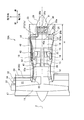
- FIG. 1 is a configuration diagram of an aircraft gas turbine engine (engine) according to a first embodiment of the present disclosure.
- FIG. 2 is a diagram for explaining the cooling system according to the first embodiment.
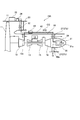
- FIG. 3 is a partial cross-sectional view showing the front main duct, the repeater, and the rear main duct according to the first embodiment.
- FIGS. 4A and 4B are views for explaining the front main duct and the rear main duct according to the first embodiment, and FIG. 4A is the IVA of the front main duct in FIG. -IVA sectional view, and FIG. 4(b) is an IVB-IVB sectional view of the rear main duct in FIG.
- FIG. 5 is an exploded perspective view of a strut according to each embodiment of the present disclosure.
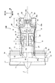
- FIG. 6 is a configuration diagram of an aircraft gas turbine engine (engine) according to a second embodiment of the present disclosure.
- FIG. 7 is a diagram for explaining the cooling system according to the second embodiment.
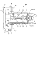
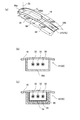
- 8(a) to 8(c) are views for explaining a sub-duct according to the second embodiment, FIG. 8(a) is a perspective view of the entire sub-duct, and FIG. 8(b) is a diagram.
- 8A is a VIIIA-VIIIA sectional view of the front auxiliary duct
- FIG. 8C is a VIIIB-VIIIB sectional view of the rear auxiliary duct in FIG. 8A.
- the gas turbine engine for aircraft equipped with the cooling system according to the present disclosure is, for example, a turbofan engine, a turbojet engine, a turboprop engine, a turboshaft engine, or the like.
- the gas turbine engine according to this embodiment is a multi-shaft gas turbine engine including a plurality of stages of compressors and turbines.
- a turbofan engine will be taken as an example of a multi-shaft gas turbine engine for aircraft. Further, for convenience of description, the turbofan engine is simply referred to as an engine.
- FIG. 1 is a configuration diagram of an engine 10A according to the present embodiment.
- FIG. 2 is a diagram for explaining the cooling system according to the present embodiment.
- the engine 10A is a biaxial turbofan engine.
- the engine 10A includes a fan 11, a low pressure compressor (compressor) 12, a high pressure compressor (compressor) 13, a combustion chamber 14, a high pressure turbine (turbine) 15, and a low pressure turbine (turbine) 16. Moreover, these are arranged on the central axis Z from the front toward the rear in the order of description.
- the hot section H of the engine 10A is located rearward of the combustion chamber 14. During operation of the engine 10A, the hot section H is heated by the combustion gas and radiant heat accompanying the combustion chamber 14.
- the engine 10A includes a fan casing 17 and a core casing 18 provided behind the fan casing 17.
- the fan casing 17 houses the fan 11.
- the core casing 18 houses the low pressure compressor 12, the high pressure compressor 13, the combustion chamber 14, the high pressure turbine 15, and the low pressure turbine 16. Further, the periphery of the core casing 18 is covered with a cover (core cowl) 19.
- An outlet guide vane 20 is provided behind the fan 11.
- the outlet guide vanes 20 connect the fan casing 17 and the core casing 18.
- the bypass flow passage 21 extends between a nacelle (not shown) that houses the engine 10A and the cover 19.
- a core channel 22 is formed inside the core casing 18.
- the gas in the core flow path 22 flows into the low pressure compressor 12 as a working fluid. In this way, the core casing 18 and the cover 19 partition the flow passage on the rear side of the fan 11 into the bypass flow passage 21 and the core flow passage 22.
- the basic configuration and operation of the engine 10A may be the same as the conventional one. That is, the fan 11 sucks gas (working fluid) and discharges it to the rear. Part of the gas that has passed through the fan 11 flows into the low-pressure compressor 12 via the core flow passage 22, and the rest is discharged rearward from the engine 10A via the bypass flow passage 21.
- the low-pressure compressor 12 compresses the gas flowing from the fan 11 and discharges it to the high-pressure compressor 13.
- the high-pressure compressor 13 further compresses the gas compressed by the low-pressure compressor 12, and supplies the gas to the combustion chamber 14.
- the combustion chamber 14 burns the mixed gas of the gas compressed by the high-pressure compressor 13 and the fuel and discharges it to the high-pressure turbine 15.
- the combustion gas rotates the high-pressure turbine 15 while expanding while passing through the high-pressure turbine 15. This rotational energy is transmitted to the high pressure compressor 13 via the high pressure shaft 25, and the high pressure compressor 13 rotates.
- the combustion gas that has passed through the high-pressure turbine 15 further expands while passing through the low-pressure turbine 16, and rotates the low-pressure turbine 16. This rotational energy is transmitted to the low pressure compressor 12 and the fan 11 via the low pressure shaft 24, and the low pressure compressor 12 and the fan 11 rotate.
- the combustion gas that has passed through the low-pressure turbine 16 is discharged to the outside of the engine 10A through the exhaust flow path 23.
- the low pressure compressor 12 and the low pressure turbine 16 are connected via a low pressure shaft 24, and the high pressure compressor 13 and the high pressure turbine 15 are connected via a high pressure shaft 25.
- the engine according to the present disclosure may be a three-shaft type engine that further includes a medium-pressure compressor (not shown) and a medium-pressure turbine (not shown).
- an exhaust frame 26 is attached to the rear part of the low-pressure turbine 16.
- the exhaust frame 26 is constituted by an inner case 26a and an outer case 26b arranged concentrically with respect to the central axis Z, and functions as a support for the low pressure turbine 16 and the tail cone 28.
- Struts 27 are provided radially between the inner case 26a and the outer case 26b with respect to the central axis Z, and connect the inner case 26a and the outer case 26b.
- the strut 27 maintains the space between the inner case 26a and the outer case 26b, and forms the exhaust flow path 23 between them.
- the outer case 26b is attached to the core casing 18, and the inner case 26a supports the tail cone 28. That is, the strut 27 connects the core casing 18 and the support body of the tail cone 28 (that is, the inner case 26a).
- a tail cone 28 is attached to the rear of the exhaust frame 26.
- the tail cone 28 is formed in a substantially conical shape, and forms at least a part of the exhaust passage 23 together with the core casing 18.
- the engine 10A includes a generator 30 as an example of an electric device that generates heat.
- the generator 30 is installed in the tail cone 28 and housed in the housing 31.
- the generator 30 generates electric power for the airframe and the engine 10A, for example.
- the generator 30 includes a rotor 30a and a stator 30b provided around the rotor 30a.
- the rotor 30a is a field (that is, a magnetic field generation source) that is rotated by the rotational energy of the low-voltage shaft 24.
- the stator 30b is an armature that generates electric power by the magnetic field of the rotor 30a.
- the rotor 30a includes a rotor core (not shown) and a plurality of magnets (not shown) held by the rotor core.
- the rotation energy of the low-pressure shaft 24 is transmitted to the rotor 30a.
- the rotor 30a is rotated by the transmission of this rotational energy.
- the stator 30b includes windings (not shown) and a stator core (not shown) that constitutes a magnetic circuit.
- the stator 30b is installed in the housing 31 while being exposed to the internal space of the housing 31.
- the output side of the generator 30 (that is, the stator 30b) is connected to the input side of the power converter 33 via the electric wire 32.
- the power converter 33 is installed, for example, on the outer periphery of the fan casing 17.
- the electric wire 32 is drawn out from the housing 31, and is connected to the power converter 33 via the main duct 40 (described later) and the outlet guide vane 20.
- the electric wire 32 is, for example, a rod-shaped metal member.
- the outer circumference of the electric wire 32 is covered with an insulating material.
- the portion located in the hot section H is covered with a heat-resistant insulating material such as polyimide resin or ceramics.
- the coating material for the other parts may be heat resistant.
- the engine 10A includes a main duct 40.
- the main duct 40 is a tubular member extending from the front to the rear of the engine 10A and constitutes a gas flow path.
- the main duct 40 is formed of a heat resistant alloy.
- a portion in front of the hot section H (for example, a front main duct 41 described later) is made of a flexible resin (for example, carbon fiber reinforced plastic (CFRP)), an elastic material such as an elastomer, or another non-metal material. It may be formed.
- CFRP carbon fiber reinforced plastic
- the main duct 40 connects the outlet passage 12a of the low-pressure compressor 12 and the internal space of the housing 31 via the radially outer side of the core casing 18 and at least one strut 27a of the struts 27.
- the main duct 40 extends from the outlet passage 12a to the housing 31 in the tail cone 28 via the space between the core casing 18 and the cover 19 and at least one strut 27a of the plurality of struts 27. It is stretched.
- the air pressure inside the outlet passage 12a is sufficiently higher than the air pressure inside the housing 31. Further, the temperature inside the outlet passage 12a is sufficiently lower than the temperature of the generator 30 during operation. Therefore, the cooling gas CG extracted from the outlet passage 12 a can flow into the housing 31 via the main duct 40 and cool the generator 30.
- the strut 27a may have a shielding structure 56 (see FIG. 5) described later. Since the strut 27a, which is a part of the main duct 40, has the shielding structure 56, it is possible to suppress the inflow of heat into the strut 27a and suppress the temperature rise of the cooling gas CG.
- the main duct 40 may be connected to the exhaust port of the blower 34 instead of being connected to the outlet flow path 12 a of the low pressure compressor 12. That is, the main duct 40 may connect the exhaust port of the blower 34 and the internal space of the housing 31.
- the blower 34 is, for example, an intake fan that cools the power converter 33 by air, and is installed on the outer periphery of the fan casing 17 together with the power converter 33. Therefore, when the main duct 40 is connected to the exhaust port of the blower 34, the main duct 40 extends inside the outlet guide vane 20.
- the temperature of the gas discharged from the blower 34 is also sufficiently lower than the temperature of the generator 30 during operation. Therefore, the generator 30 can be cooled by causing the gas discharged from the blower 34 to flow into the housing 31 through the main duct 40.
- the cooling gas CG from the main duct 40 flows into the housing 31.
- the cooling system of the present embodiment may have at least one of the discharge port 31a and the exhaust duct 40a.
- the outlet 31 a is formed on the wall surface of the housing 31.
- the exhaust duct 40 a extends from the housing 31 into the struts 27 (struts 27 b) other than the struts 27 (struts 27 a) provided with the main duct 40, and opens to the outer surface of the core casing 18.
- the hot section H is heated as the combustion chamber 14 burns.
- the above-mentioned electric wire 32 is laid near the hot section H. Therefore, the electric wire 32 is easily damaged by the heat from the hot section H.
- the main duct 40 may house at least a portion of the electric wire 32 located in the hot section H. As described above, a relatively low temperature gas flows through the main duct 40. The main duct 40 itself also shields heat. Therefore, the electric wire 32 can be protected from the heat of the hot section H.
- the main duct 40 may include a front main duct 41, a rear main duct 42, and a repeater 43.
- the upstream side of the front main duct 41 is connected to the outlet passage 12 a of the low pressure compressor 12 or the exhaust port of the blower 34.
- the rear main duct 42 is provided at least in the hot section H, and its downstream side is connected to the housing 31.
- the repeater 43 is provided outside the core casing 18 in the radial direction, and connects and connects the downstream side of the front main duct 41 and the upstream side of the rear main duct 42.
- the main duct 40 may be divided into a front duct and a rear duct with the repeater 43 interposed therebetween.
- FIG. 3 is a partial cross-sectional view showing the front main duct 41, the repeater 43, and the rear main duct 42 according to the present embodiment.
- 4(a) and 4(b) are views for explaining the front main duct 41 and the rear main duct 42
- FIG. 4(a) is an IVA-IVA sectional view of the front main duct 41 in FIG. 4(b) is a IVB-IVB sectional view of the rear main duct 42 in FIG.
- the repeater 43 includes a hollow box body 44, a terminal board 45 installed inside the box body 44, and a receptacle (e.g., an outer surface 44 a of the box body 44) attached to the box body 44.
- the box body 44 is configured to allow the gas to flow from the front main duct 41 to the rear main duct 42 and to suppress the leakage of the gas from other portions as much as possible.
- a plug (male connector) 49 of the front main duct 41 is connected to the receptacle 46.
- a plug (male connector) 50 of the rear main duct 42 is connected to the receptacle 47.
- Through holes are formed in the receptacles 46 and 47 to communicate between the corresponding ducts and the internal space of the box body 44, whereby the front main duct 41 via the relay 43 is rearwardly extended. The flow of the cooling gas CG to the side main duct 42 is allowed.
- An electric wire 32 connected to the generator 30 is housed in the rear main duct 42.
- the electric wire 32 is pulled out (that is, exposed) from the receptacle 47 into the relay 43, and is connected to the terminal board 45. That is, the electric wire 32 is connected to the generator 30 from the terminal board 45 through the rear main duct 42.
- a plug (male connector) 51 of the electric wire 32 is connected to the receptacle 48, and the electric wire 32 is connected to the terminal board 45.
- the output side of the generator 30 and the input side of the power converter 33 are electrically connected via the relay 43 (terminal board 45).
- the front main duct 41 has a tubular main body 52.
- the front main duct 41 is located in front of the hot section H and is not easily damaged by heat. Therefore, the main body portion 52 may be formed of a heat-resistant alloy similarly to the rear main duct 42, and has a flexible resin (for example, carbon fiber reinforced plastic (CFRP)), an elastic material such as an elastomer, or other material. It may be formed of a non-metallic material.
- CFRP carbon fiber reinforced plastic
- the rear main duct 42 has a tubular main body 53, a heat insulating material 54 provided inside the main body 53, and a sheath 55 provided inside the heat insulating material 54. ..
- the main body 53 and the sheath 55 are formed in a tubular shape, and are concentrically positioned with a space in which the heat insulating material 54 is provided therebetween. That is, the main body 53 and the sheath 55 form a double wall structure.
- the main body 53 and the sheath 55 are formed of a heat resistant material. Such a material is, for example, a heat resistant alloy.
- the heat insulating material 54 is provided between the inner surface of the main body 53 and the outer surface of the sheath 55.
- the heat insulating material 54 together with the sheath 55, prevents excessive heat transfer (radiation) to the electric wires 32. That is, the main duct 40 (rear side main duct 42) has the shielding structure 56 against the heat from the hot section H and protects the electric wire 32.
- the sheath 55 has a cavity 57 formed inside thereof.
- the cavity 57 accommodates the electric wire 32 and secures the flow of gas. That is, the cross-sectional area of the cavity 57 orthogonal to the longitudinal direction of the rear main duct 42 is set to a value larger than the cross-sectional area of the electric wire 32 and capable of ensuring the flow of gas.
- FIG. 5 is an exploded perspective view of the strut 27a that also serves as the main duct 40 (rear side main duct 42).
- Each of the struts 27, including the struts 27a, has a wing-shaped cross section and extends in the radial direction.
- the struts 27 are made of a heat-resistant alloy and have sufficient mechanical strength to stably connect the inner case 26a and the outer case 26b.
- the strut 27a functions as the main body portion 53 of the main duct 40 (rear side main duct 42) and houses the electric wire 32. Therefore, the heat insulating material 54 is provided inside the strut 27 a, and the sheath 55 is provided inside the heat insulating material 54.
- the portion of the sheath 55 provided inside the strut 27a has a flat cross section similar to that of the strut 27a. Accordingly, the electric wire 32 may also have a flat cross section (for example, a rectangular cross section).
- the portion of the electric wire 32 that is laid in the hot section H is housed in the main duct 40 (rear side main duct 42).
- the cooling gas CG flows toward the housing 31 in the main duct 40 (rear side main duct 42 ). Therefore, the portion of the electric wire 32 laid in the hot section H is shielded from the heat of the hot section H by the main duct 40 (rear side main duct 42) and cooled by the cooling gas CG. Thereby, the heat damage of the electric wire 32 can be prevented.
- the number of the electric wires 32 accommodated in the strut 27a is not limited to one, and may be plural.
- the number of main ducts 40 is not limited to one. That is, the cooling system according to the present embodiment includes at least one main duct 40.
- the number of electric wires 32 accommodated in each main duct 40 can be reduced. As a result, the size (for example, outer diameter) of the main duct 40 is reduced, and the degree of freedom of the laid portion is improved.
- the number of struts 27a may be increased according to the number.
- FIG. 6 is a configuration diagram of the engine 10B according to the second embodiment.
- FIG. 7 is a diagram for explaining the cooling system according to the second embodiment.
- 8A to 8C are views for explaining the sub-duct 60 according to the second embodiment.
- FIG. 8A is a perspective view of the sub-duct 60 as a whole, and
- FIG. 8A is a VIIIA-VIIIA sectional view of the front auxiliary duct 61 in FIG. 8A, and
- FIG. 8C is a VIIIB-VIIIB sectional view of the rear auxiliary duct 62 in FIG. 8A.
- the cooling system according to the second embodiment includes a sub duct (second duct) 60 in addition to the main duct (first duct) 40 described above. Further, in the second embodiment, the auxiliary duct 60 houses the electric wire 32 that connects the generator 30 and the power converter 33. Furthermore, the housing 31 does not have an exhaust port for the cooling gas CG that opens inside the tail cone 28. Since other configurations are similar to those of the first embodiment, the same reference numerals are given to the overlapping configurations, and the description thereof will be omitted.
- the auxiliary duct 60 also constitutes a gas flow path.
- the sub duct 60 is also made of a heat resistant alloy.
- a portion in front of the hot section H (for example, a front auxiliary duct 61 described later) has a flexible resin (for example, carbon fiber reinforced plastic (CFRP)), an elastic material such as an elastomer, or other non-metal material. May be formed by.
- CFRP carbon fiber reinforced plastic
- the auxiliary duct 60 is provided at the rear of the fan 11 via the radially outer side of the core casing 18 and the struts 27b other than the struts 27a of the struts 27 through which the main duct 40 passes.
- the bypass passage 21 and the inner space of the housing 31 are communicated with each other.
- the sub-duct 60 extends from the bypass passage 21 to the housing 31 via the radially outer side of the core casing 18 and the struts 27b.
- the auxiliary duct 60 has an intake port 60a.
- the intake port 60a is opened in front of the outlet guide vane 20, for example, on the outer peripheral surface of the core casing 18 facing the bypass passage 21.
- the sub duct 60 is branched at a position radially outward of the strut 27b on which the sub duct 60 is laid, and opens toward the exhaust passage 23 as an exhaust port 60b.
- the sub-duct 60 includes a channel member extending between the core casing 18 and the cover 19 from the front to the rear of the engine 10B.
- the channel member has a C-shaped cross section that opens toward the cover 19. The opening of the channel member toward the cover 19 is covered by the cover 19, so that the space inside the sub duct 60 is surrounded by the sub duct 60 and the cover 19.
- the electric wire 32 is drawn out from the housing 31, and is connected to the power converter 33 via the auxiliary duct 60 and the outlet guide vane 20.
- the part of the sub duct 60 from the strut 27b to the housing 31 has the same structure as the part of the main duct 40 from the strut 27a to the housing 31. Therefore, the strut 27b has the same configuration as the strut 27a (see FIG. 5).
- the cooling gas CG extracted from the outlet passage 12a of the low pressure compressor 12 flows into the housing 31 via the main duct 40 and cools the generator 30.
- the housing 31 does not have the exhaust port for the cooling gas CG that opens inside the tail cone 28. Instead, the sub-duct 60 is connected to the housing 31. Therefore, the cooling gas CG that has cooled the generator 30 flows into the sub duct 60, and is discharged from the exhaust port 60b via the struts 27b forming a part of the sub duct 60.
- the cooling gas CG flows from the housing 31 via the strut 27b to the exhaust port 60b.
- the circulation of the cooling gas CG also cools the portion of the electric wire 32 from the housing 31 to the strut 27b.
- the exhaust gas EG of the fan 11 flows into the intake port 60a and is exhausted from the exhaust port 60b.
- the electric wire 32 is also cooled by the circulation of the exhaust gas EG. That is, the entire electric wire 32 accommodated in the sub duct 60 is cooled by the cooling gas CG or the exhaust gas EG. As a result, it is possible to prevent heat damage to the electric wire 32 due to heat from the hot section H.
- the auxiliary duct 60 may include a front auxiliary duct 61 connected to the bypass passage 21 and a rear auxiliary duct 62 extending from the front auxiliary duct 61 to the housing 31.
- the rear auxiliary duct 62 is provided at least in the hot section H.
- the rear sub duct 62 may have the above-described shielding structure 56. That is, the heat insulating material 54 is provided on the inner surface of the rear auxiliary duct 62, and the sheath 55 is provided on the inner surface of the heat insulating material 54. Both the heat insulating material 54 and the sheath 55 have a cross section similar to that of the rear auxiliary duct 62, and prevent excessive heat transfer (radiation) to the electric wires 32.
- the front sub-duct 61 is provided at a portion where heat resistance is not required.
- the front auxiliary duct 61 may be formed of, for example, a flexible resin (for example, carbon fiber reinforced plastic (CFRP)), an elastic material such as an elastomer, or other non-metallic material. In this case, the weight is lighter than that of the rear auxiliary duct 62.
- CFRP carbon fiber reinforced plastic
- the number of electric wires 32 accommodated in the sub duct 60 is arbitrary. For example, as shown in FIGS. 8B and 8C, a plurality of electric wires 32 may be accommodated.
- the main duct 40 is connected to the outlet passage 12a of the low-pressure compressor 12 or the exhaust port of the blower 34.
- the auxiliary duct 60 may also be connected to the exhaust port of the blower 34.
- the main duct 40 is connected to the outlet passage 12 a of the low pressure compressor 12
- the auxiliary duct 60 may be connected to the exhaust port of the blower 34. That is, at least one of the main duct 40 (upstream of the front main duct 41) and the sub duct 60 (upstream of the front sub duct 61) may be connected to the exhaust port of the blower 34.
- the auxiliary duct 60 When the auxiliary duct 60 is connected to the exhaust port of the blower 34, the auxiliary duct 60 extends inside the outlet guide vane 20 and is connected to the exhaust port of the blower 34.
- the electric wire 32 described above is housed in the sub duct 60.
- a plurality of blowers 34 may be provided.
- the main duct 40 and the sub duct 60 may be individually connected to the exhaust ports of the corresponding blowers 34.
- the use of each blower 34 is not limited to cooling and may be, for example, ventilation or ventilation.
- the cooling system according to each embodiment adopts air cooling using a duct. Therefore, it is possible to cool the electric equipment installed behind the turbine with a simpler configuration than the oil cooling system.
- the cooling system described above does not exclude the oil cooling system. That is, the cooling system of this embodiment can be used together with the oil cooling system.
Landscapes
- Engineering & Computer Science (AREA)
- Chemical & Material Sciences (AREA)
- Combustion & Propulsion (AREA)
- Mechanical Engineering (AREA)
- General Engineering & Computer Science (AREA)
- Aviation & Aerospace Engineering (AREA)
- Physics & Mathematics (AREA)
- Fluid Mechanics (AREA)
- Motor Or Generator Cooling System (AREA)
- Structures Of Non-Positive Displacement Pumps (AREA)
Abstract
Description
前記ストラットのうちの少なくとも1つと前記コアケーシングの径方向外側とを経由して、前記コンプレッサの出口流路又は前記ガスタービンエンジンに設置されるブロアの排気口と前記ハウジングの内部空間とを連通する少なくとも1つの主ダクトと
を備えることを要旨とする。
本開示の第1実施形態について説明する。
図1は、本実施形態に係るエンジン10Aの構成図である。図2は、本実施形態に係る冷却システムを説明するための図である。図1に示すように、エンジン10Aは二軸式のターボファンエンジンである。エンジン10Aは、ファン11と、低圧コンプレッサ(コンプレッサ)12と、高圧コンプレッサ(コンプレッサ)13と、燃焼室14と、高圧タービン(タービン)15、低圧タービン(タービン)16とを備えている。また、これらは、記載順に、前方から後方に向けて中心軸Z上に配列している。エンジン10AのホットセクションHは燃焼室14から後方に位置する。エンジン10Aの稼働中、ホットセクションHは、燃焼室14に伴う燃焼ガスや輻射熱によって加熱される。
本開示の第2実施形態について説明する。
図6は、第2実施形態に係るエンジン10Bの構成図である。図7は、第2実施形態に係る冷却システムを説明するための図である。図8(a)~図8(c)は、第2実施形態に係る副ダクト60を説明するための図であり、図8(a)は副ダクト60全体の斜視図、図8(b)は図8(a)における前側副ダクト61のVIIIA-VIIIA断面図、図8(c)は図8(a)における後側副ダクト62のVIIIB-VIIIB断面図である。
Claims (6)
- 航空機用ガスタービンエンジンの冷却システムであって、
コンプレッサ、燃焼室及びタービンを収容するコアケーシングと、
前記コアケーシングと共に前記タービンの排気流路の少なくとも一部を形成するテールコーンと、
前記コアケーシングと前記テールコーンの支持体とを連結するストラットと、
前記テールコーン内に設置され、電気機器を収容するハウジングと、
前記ストラットのうちの少なくとも1つと前記コアケーシングの径方向外側とを経由して、前記コンプレッサの出口流路又は前記ガスタービンエンジンに設置されるブロアの排気口と前記ハウジングの内部空間とを連通させる少なくとも1つの主ダクトと
を備える冷却システム。 - 前記電気機器に接続する電線を更に備え、
前記主ダクトは、
前記コンプレッサの前記出口流路又は前記ブロアの前記排気口に接続する前側主ダクトと、
前記ハウジングに接続する後側主ダクトと、
前記コアケーシングの径方向外側に設けられ、前記前側主ダクト及び前記後側主ダクトを連通且つ連結する中継器と
を含み、
前記中継器は端子盤を備え、
前記電線は、前記端子盤から前記後側主ダクトを通じて前記電気機器に接続されている
請求項1に記載の冷却システム。 - 前記ハウジングは排気口を有する
請求項2に記載の冷却システム。 - 前記後側主ダクトは、前記燃焼室及び前記タービンからの熱に対する遮蔽構造を有する
請求項2または3に記載の冷却システム。 - 前記コアケーシングの径方向外側と前記ストラットのうち前記主ダクトが経由するストラット以外のストラットとを経由して、ファン後方のバイパス流路と前記ハウジングの前記内部空間とを連通させる副ダクト
を更に備え、
前記副ダクトは、当該副ダクトが敷設される前記ストラットよりも径方向外方の位置で分岐し、前記排気流路に向けて開口している
請求項1に記載の冷却システム。 - 前記副ダクトに収容され、前記電気機器に接続する電線を更に備え、
前記副ダクトは、
前記バイパス流路に接続する前側副ダクトと、
前記前側副ダクトから前記ハウジングまで延伸する後側副ダクトと、
を含み、
前記後側副ダクトは、前記燃焼室及び前記タービンからの熱に対する遮蔽構造を有する
請求項5に記載の冷却システム。
Priority Applications (4)
| Application Number | Priority Date | Filing Date | Title |
|---|---|---|---|
| JP2020572153A JP7143904B2 (ja) | 2019-02-13 | 2020-01-30 | 航空機用ガスタービンエンジンの冷却システム |
| EP20756038.4A EP3926157B1 (en) | 2019-02-13 | 2020-01-30 | Cooling system for aircraft gas turbine engine |
| CA3127554A CA3127554C (en) | 2019-02-13 | 2020-01-30 | Cooling system for aircraft gas turbine engine |
| US17/304,947 US11408344B2 (en) | 2019-02-13 | 2021-06-29 | Cooling system for aircraft gas turbine engine |
Applications Claiming Priority (2)
| Application Number | Priority Date | Filing Date | Title |
|---|---|---|---|
| JP2019-023511 | 2019-02-13 | ||
| JP2019023511 | 2019-02-13 |
Related Child Applications (1)
| Application Number | Title | Priority Date | Filing Date |
|---|---|---|---|
| US17/304,947 Continuation US11408344B2 (en) | 2019-02-13 | 2021-06-29 | Cooling system for aircraft gas turbine engine |
Publications (1)
| Publication Number | Publication Date |
|---|---|
| WO2020166342A1 true WO2020166342A1 (ja) | 2020-08-20 |
Family
ID=72044190
Family Applications (1)
| Application Number | Title | Priority Date | Filing Date |
|---|---|---|---|
| PCT/JP2020/003293 Ceased WO2020166342A1 (ja) | 2019-02-13 | 2020-01-30 | 航空機用ガスタービンエンジンの冷却システム |
Country Status (5)
| Country | Link |
|---|---|
| US (1) | US11408344B2 (ja) |
| EP (1) | EP3926157B1 (ja) |
| JP (1) | JP7143904B2 (ja) |
| CA (1) | CA3127554C (ja) |
| WO (1) | WO2020166342A1 (ja) |
Cited By (4)
| Publication number | Priority date | Publication date | Assignee | Title |
|---|---|---|---|---|
| CN114645739A (zh) * | 2020-12-18 | 2022-06-21 | 通用电气航空系统有限责任公司 | 涡轮发动机的电支柱 |
| CN115126603A (zh) * | 2021-03-24 | 2022-09-30 | 通用电气公司 | 具有热回收系统的燃气涡轮发动机 |
| FR3129427A1 (fr) * | 2021-11-22 | 2023-05-26 | Safran Aircraft Engines | Carter d’echappement comportant un bras creux traverse par un element conducteur de transmission de puissance |
| GB2600524B (en) * | 2020-10-27 | 2024-10-02 | Rtx Corp | Power cable cooling system in a gas turbine engine |
Families Citing this family (24)
| Publication number | Priority date | Publication date | Assignee | Title |
|---|---|---|---|---|
| FR3099912B1 (fr) * | 2019-08-18 | 2021-08-13 | Safran Nacelles | Entrée d’air d’une nacelle d’une turbomachine d’aéronef |
| US11719113B2 (en) | 2020-02-05 | 2023-08-08 | Raytheon Technologies Corporation | Cooling system for power cables in a gas turbine engine |
| FR3110939B1 (fr) * | 2020-05-27 | 2022-09-09 | Safran Trans Systems | Turbomachine equipee de machines electriques accouplees a une surface d’accouplement |
| US11585291B2 (en) * | 2020-09-11 | 2023-02-21 | Raytheon Technologies Corporation | Tail cone ejector for power cable cooling system in a gas turbine engine |
| US11795837B2 (en) * | 2021-01-26 | 2023-10-24 | General Electric Company | Embedded electric machine |
| US11821370B2 (en) * | 2021-11-18 | 2023-11-21 | Hamilton Sundstrand Corporation | Cooling system for tail cone mounted generator |
| EP4223986B1 (en) * | 2022-02-07 | 2026-04-08 | Rolls-Royce Deutschland Ltd & Co KG | Turbine generator system |
| US11927137B2 (en) | 2022-03-21 | 2024-03-12 | Ge Infrastructure Technology Llc | System and method for insulating components in an exhaust gas flow from a gas turbine |
| US20240060459A1 (en) * | 2022-08-19 | 2024-02-22 | Pratt & Whitney Canada Corp. | Exhaust assembly for purging a nacelle cavity of a propulsion system |
| US12366201B2 (en) | 2023-02-17 | 2025-07-22 | General Electric Company | Reverse flow gas turbine engine having electric machine |
| EP4417796B1 (en) * | 2023-02-17 | 2026-03-04 | General Electric Company | Reverse flow gas turbine engine having electric machine |
| US12319417B2 (en) | 2023-02-17 | 2025-06-03 | General Electric Company | Reverse flow gas turbine engine having electric machine |
| US12486797B2 (en) * | 2023-02-17 | 2025-12-02 | General Electric Company | Reverse flow gas turbine engine having electric machine |
| US12416262B2 (en) | 2023-02-17 | 2025-09-16 | General Electric Company | Reverse flow gas turbine engine having electric machine |
| US12188414B2 (en) * | 2023-02-17 | 2025-01-07 | General Electric Company | Reverse flow gas turbine engine having electric machine |
| US12510025B2 (en) | 2023-02-17 | 2025-12-30 | General Electric Company | Reverse flow gas turbine engine having electric machine |
| US12460576B2 (en) * | 2023-02-17 | 2025-11-04 | General Electric Company | Reverse flow gas turbine engine having electric machine |
| JP2024136507A (ja) * | 2023-03-24 | 2024-10-04 | 本田技研工業株式会社 | 電力システム及び移動体 |
| GB202307055D0 (en) * | 2023-05-12 | 2023-06-28 | Rolls Royce Plc | An accessory power module |
| US12359587B2 (en) * | 2023-09-12 | 2025-07-15 | Rolls-Royce North American Technologies, Inc. | Gas turbine engine power cable cooling |
| FR3154451B1 (fr) * | 2023-10-20 | 2025-09-12 | Safran Aircraft Engines | Circuit de ventilation pour turbomachine |
| US12264623B1 (en) * | 2024-01-18 | 2025-04-01 | Honeywell International Inc. | System for electric machine associated with gas turbine engine |
| US12595765B2 (en) * | 2024-02-02 | 2026-04-07 | Rtx Corporation | Bifurcation integrated electrical system for hybrid aircraft propulsion system |
| US12553384B2 (en) * | 2024-08-02 | 2026-02-17 | Rtx Corporation | High pressure cooling systems for hybrid and conventional engines |
Citations (9)
| Publication number | Priority date | Publication date | Assignee | Title |
|---|---|---|---|---|
| US5265408A (en) * | 1992-02-13 | 1993-11-30 | Allied-Signal Inc. | Exhaust eductor cooling system |
| JP2005507044A (ja) * | 2001-10-29 | 2005-03-10 | プラット アンド ホイットニー カナダ コーポレイション | 補助動力装置設備のための受動型冷却システム |
| JP2006153013A (ja) | 2004-11-25 | 2006-06-15 | Snecma | 後部発電機を有する2スプール型バイパスターボジェット、および空気流接続装置ならびにシステム |
| US20120227371A1 (en) * | 2011-03-09 | 2012-09-13 | General Electric Company | System for cooling and purging exhaust section of gas turbine engine |
| US20130133336A1 (en) * | 2011-11-28 | 2013-05-30 | Barry Barnett | Support for electric machine in a turbine engine |
| US20140079530A1 (en) * | 2012-09-14 | 2014-03-20 | Pratt & Whitney Canada Corp. | Air cooling design for tail-cone generator installation |
| US9092369B2 (en) * | 2012-10-31 | 2015-07-28 | International Business Machines Corporation | Tracking specific Java native interface invocations of system and library calls |
| US20180051702A1 (en) * | 2016-08-22 | 2018-02-22 | General Electric Company | Embedded electric machine |
| JP2018184162A (ja) * | 2017-04-21 | 2018-11-22 | ゼネラル・エレクトリック・カンパニイ | 航空機のための推進システム |
Family Cites Families (5)
| Publication number | Priority date | Publication date | Assignee | Title |
|---|---|---|---|---|
| US6092360A (en) * | 1998-07-01 | 2000-07-25 | The Boeing Company | Auxiliary power unit passive cooling system |
| FR2964481B1 (fr) * | 2010-09-08 | 2012-08-31 | Thales Sa | Dispositif ameliore pour la configuration d'un composant programmable, systeme integrant ce dispositif, et procede associe |
| FR3054858B1 (fr) * | 2016-08-03 | 2018-09-07 | Safran Aircraft Engines | Turbomachine comportant un dispositif d'entrainement d'un equipement dispose dans le cone d'echappement |
| US10801410B2 (en) * | 2018-04-12 | 2020-10-13 | Raytheon Technologies Corporation | Thermal management of tail cone mounted generator |
| US11162379B2 (en) * | 2019-03-15 | 2021-11-02 | Hamilton Sundstrand Corporation | Temperature control device for tail cone mounted generator |
-
2020
- 2020-01-30 JP JP2020572153A patent/JP7143904B2/ja active Active
- 2020-01-30 EP EP20756038.4A patent/EP3926157B1/en active Active
- 2020-01-30 WO PCT/JP2020/003293 patent/WO2020166342A1/ja not_active Ceased
- 2020-01-30 CA CA3127554A patent/CA3127554C/en active Active
-
2021
- 2021-06-29 US US17/304,947 patent/US11408344B2/en active Active
Patent Citations (9)
| Publication number | Priority date | Publication date | Assignee | Title |
|---|---|---|---|---|
| US5265408A (en) * | 1992-02-13 | 1993-11-30 | Allied-Signal Inc. | Exhaust eductor cooling system |
| JP2005507044A (ja) * | 2001-10-29 | 2005-03-10 | プラット アンド ホイットニー カナダ コーポレイション | 補助動力装置設備のための受動型冷却システム |
| JP2006153013A (ja) | 2004-11-25 | 2006-06-15 | Snecma | 後部発電機を有する2スプール型バイパスターボジェット、および空気流接続装置ならびにシステム |
| US20120227371A1 (en) * | 2011-03-09 | 2012-09-13 | General Electric Company | System for cooling and purging exhaust section of gas turbine engine |
| US20130133336A1 (en) * | 2011-11-28 | 2013-05-30 | Barry Barnett | Support for electric machine in a turbine engine |
| US20140079530A1 (en) * | 2012-09-14 | 2014-03-20 | Pratt & Whitney Canada Corp. | Air cooling design for tail-cone generator installation |
| US9092369B2 (en) * | 2012-10-31 | 2015-07-28 | International Business Machines Corporation | Tracking specific Java native interface invocations of system and library calls |
| US20180051702A1 (en) * | 2016-08-22 | 2018-02-22 | General Electric Company | Embedded electric machine |
| JP2018184162A (ja) * | 2017-04-21 | 2018-11-22 | ゼネラル・エレクトリック・カンパニイ | 航空機のための推進システム |
Non-Patent Citations (1)
| Title |
|---|
| See also references of EP3926157A4 |
Cited By (12)
| Publication number | Priority date | Publication date | Assignee | Title |
|---|---|---|---|---|
| GB2600524B (en) * | 2020-10-27 | 2024-10-02 | Rtx Corp | Power cable cooling system in a gas turbine engine |
| GB2630505A (en) * | 2020-10-27 | 2024-11-27 | Rtx Corp | Power cable cooling system in a gas turbine engine |
| GB2630505B (en) * | 2020-10-27 | 2025-06-11 | Rtx Corp | Power cable cooling system in a gas turbine engine |
| CN114645739A (zh) * | 2020-12-18 | 2022-06-21 | 通用电气航空系统有限责任公司 | 涡轮发动机的电支柱 |
| EP4015774A1 (en) * | 2020-12-18 | 2022-06-22 | GE Aviation Systems LLC | Electrical strut for a turbine engine |
| US11852024B2 (en) | 2020-12-18 | 2023-12-26 | Ge Aviation Systems Llc | Electrical strut for a turbine engine |
| EP4343121A3 (en) * | 2020-12-18 | 2024-04-17 | GE Aviation Systems LLC | Electrical strut for a turbine engine |
| CN114645739B (zh) * | 2020-12-18 | 2024-09-20 | 通用电气航空系统有限责任公司 | 涡轮发动机的电支柱 |
| CN115126603A (zh) * | 2021-03-24 | 2022-09-30 | 通用电气公司 | 具有热回收系统的燃气涡轮发动机 |
| CN115126603B (zh) * | 2021-03-24 | 2025-03-07 | 通用电气公司 | 具有热回收系统的燃气涡轮发动机 |
| US12510027B2 (en) | 2021-03-24 | 2025-12-30 | General Electric Company | Gas turbine engines with heat recovery systems |
| FR3129427A1 (fr) * | 2021-11-22 | 2023-05-26 | Safran Aircraft Engines | Carter d’echappement comportant un bras creux traverse par un element conducteur de transmission de puissance |
Also Published As
| Publication number | Publication date |
|---|---|
| JP7143904B2 (ja) | 2022-09-29 |
| EP3926157B1 (en) | 2024-05-15 |
| EP3926157A4 (en) | 2022-11-16 |
| US20210324799A1 (en) | 2021-10-21 |
| CA3127554A1 (en) | 2020-08-20 |
| EP3926157A1 (en) | 2021-12-22 |
| JPWO2020166342A1 (ja) | 2021-11-11 |
| CA3127554C (en) | 2023-07-18 |
| US11408344B2 (en) | 2022-08-09 |
Similar Documents
| Publication | Publication Date | Title |
|---|---|---|
| US11408344B2 (en) | Cooling system for aircraft gas turbine engine | |
| US11791691B2 (en) | Generator cooling system for turbo-fan engine | |
| US7855483B2 (en) | Turbomachine with integral generator/starter | |
| JP4463810B2 (ja) | 航空機用エンジン装置 | |
| EP3862542B1 (en) | Cooling system for power cables in a gas turbine engine | |
| US8857192B2 (en) | Accessory gearbox with a starter/generator | |
| US11637475B2 (en) | Terminal block for integrated tail cone and mounted generator | |
| CN114909218B (zh) | 包括嵌入式电机和相关联冷却系统的燃气涡轮发动机 | |
| US20250122812A1 (en) | Turbomachine comprising an outlet cone incorporating components cooled by circulation of a cooling flow | |
| CN108137165A (zh) | 具有组合发动机和冷却排气的发动机组件 | |
| US20160290236A1 (en) | Turbo-engine including two separate ventilation flows | |
| CN113167128B (zh) | 用于包括改进了附接的叶片的飞行器风扇的电气模块 | |
| CN114076030B (zh) | 用于发电机组件的连接结构 | |
| CN114909222B (zh) | 包括嵌入式电机和相关联冷却系统的燃气涡轮发动机 | |
| CN114915102B (zh) | 用于集成到推进发动机中的电机 | |
| CN114915101B (zh) | 用于集成到推进发动机中的电机 | |
| CN104350237A (zh) | 飞机发动机传动轴容器组件和组装所述组件的方法 | |
| CN114076034A (zh) | 包括嵌入式电机和相关冷却系统的燃气涡轮发动机 | |
| US11047251B2 (en) | Routing for electrical communication in gas turbine engines | |
| US10590787B2 (en) | Gas turbine engine | |
| US11591987B2 (en) | Turbomachine with electric machine comprising a rotor ring attached to the fan | |
| CN114865847A (zh) | 具有嵌入式电机的航空发动机的轴承腔结构和航空发动机 | |
| US20250293563A1 (en) | Electric machine with cooling features | |
| US11815015B2 (en) | Gas turbine system and moving body including the same | |
| CN118640096A (zh) | 一种集成嵌入电机的低压功率提取系统 |
Legal Events
| Date | Code | Title | Description |
|---|---|---|---|
| 121 | Ep: the epo has been informed by wipo that ep was designated in this application |
Ref document number: 20756038 Country of ref document: EP Kind code of ref document: A1 |
|
| ENP | Entry into the national phase |
Ref document number: 2020572153 Country of ref document: JP Kind code of ref document: A |
|
| ENP | Entry into the national phase |
Ref document number: 3127554 Country of ref document: CA |
|
| NENP | Non-entry into the national phase |
Ref country code: DE |
|
| ENP | Entry into the national phase |
Ref document number: 2020756038 Country of ref document: EP Effective date: 20210913 |