WO2020166637A1 - 燃料噴射管用鋼管およびそれを用いた燃料噴射管 - Google Patents
燃料噴射管用鋼管およびそれを用いた燃料噴射管 Download PDFInfo
- Publication number
- WO2020166637A1 WO2020166637A1 PCT/JP2020/005434 JP2020005434W WO2020166637A1 WO 2020166637 A1 WO2020166637 A1 WO 2020166637A1 JP 2020005434 W JP2020005434 W JP 2020005434W WO 2020166637 A1 WO2020166637 A1 WO 2020166637A1
- Authority
- WO
- WIPO (PCT)
- Prior art keywords
- steel pipe
- fuel injection
- less
- pipe
- steel
- Prior art date
- Legal status (The legal status is an assumption and is not a legal conclusion. Google has not performed a legal analysis and makes no representation as to the accuracy of the status listed.)
- Ceased
Links
Images
Classifications
-
- C—CHEMISTRY; METALLURGY
- C21—METALLURGY OF IRON
- C21D—MODIFYING THE PHYSICAL STRUCTURE OF FERROUS METALS; GENERAL DEVICES FOR HEAT TREATMENT OF FERROUS OR NON-FERROUS METALS OR ALLOYS; MAKING METAL MALLEABLE, e.g. BY DECARBURISATION OR TEMPERING
- C21D9/00—Heat treatment, e.g. annealing, hardening, quenching or tempering, adapted for particular articles; Furnaces therefor
- C21D9/08—Heat treatment, e.g. annealing, hardening, quenching or tempering, adapted for particular articles; Furnaces therefor for tubular bodies or pipes
- C21D9/085—Cooling or quenching
-
- C—CHEMISTRY; METALLURGY
- C21—METALLURGY OF IRON
- C21D—MODIFYING THE PHYSICAL STRUCTURE OF FERROUS METALS; GENERAL DEVICES FOR HEAT TREATMENT OF FERROUS OR NON-FERROUS METALS OR ALLOYS; MAKING METAL MALLEABLE, e.g. BY DECARBURISATION OR TEMPERING
- C21D9/00—Heat treatment, e.g. annealing, hardening, quenching or tempering, adapted for particular articles; Furnaces therefor
- C21D9/08—Heat treatment, e.g. annealing, hardening, quenching or tempering, adapted for particular articles; Furnaces therefor for tubular bodies or pipes
- C21D9/14—Heat treatment, e.g. annealing, hardening, quenching or tempering, adapted for particular articles; Furnaces therefor for tubular bodies or pipes wear-resistant or pressure-resistant pipes
-
- C—CHEMISTRY; METALLURGY
- C21—METALLURGY OF IRON
- C21D—MODIFYING THE PHYSICAL STRUCTURE OF FERROUS METALS; GENERAL DEVICES FOR HEAT TREATMENT OF FERROUS OR NON-FERROUS METALS OR ALLOYS; MAKING METAL MALLEABLE, e.g. BY DECARBURISATION OR TEMPERING
- C21D1/00—General methods or devices for heat treatment, e.g. annealing, hardening, quenching or tempering
- C21D1/18—Hardening; Quenching with or without subsequent tempering
-
- C—CHEMISTRY; METALLURGY
- C21—METALLURGY OF IRON
- C21D—MODIFYING THE PHYSICAL STRUCTURE OF FERROUS METALS; GENERAL DEVICES FOR HEAT TREATMENT OF FERROUS OR NON-FERROUS METALS OR ALLOYS; MAKING METAL MALLEABLE, e.g. BY DECARBURISATION OR TEMPERING
- C21D1/00—General methods or devices for heat treatment, e.g. annealing, hardening, quenching or tempering
- C21D1/18—Hardening; Quenching with or without subsequent tempering
- C21D1/19—Hardening; Quenching with or without subsequent tempering by interrupted quenching
-
- C—CHEMISTRY; METALLURGY
- C21—METALLURGY OF IRON
- C21D—MODIFYING THE PHYSICAL STRUCTURE OF FERROUS METALS; GENERAL DEVICES FOR HEAT TREATMENT OF FERROUS OR NON-FERROUS METALS OR ALLOYS; MAKING METAL MALLEABLE, e.g. BY DECARBURISATION OR TEMPERING
- C21D1/00—General methods or devices for heat treatment, e.g. annealing, hardening, quenching or tempering
- C21D1/18—Hardening; Quenching with or without subsequent tempering
- C21D1/19—Hardening; Quenching with or without subsequent tempering by interrupted quenching
- C21D1/22—Martempering
-
- C—CHEMISTRY; METALLURGY
- C21—METALLURGY OF IRON
- C21D—MODIFYING THE PHYSICAL STRUCTURE OF FERROUS METALS; GENERAL DEVICES FOR HEAT TREATMENT OF FERROUS OR NON-FERROUS METALS OR ALLOYS; MAKING METAL MALLEABLE, e.g. BY DECARBURISATION OR TEMPERING
- C21D1/00—General methods or devices for heat treatment, e.g. annealing, hardening, quenching or tempering
- C21D1/18—Hardening; Quenching with or without subsequent tempering
- C21D1/25—Hardening, combined with annealing between 300 degrees Celsius and 600 degrees Celsius, i.e. heat refining ("Vergüten")
-
- C—CHEMISTRY; METALLURGY
- C21—METALLURGY OF IRON
- C21D—MODIFYING THE PHYSICAL STRUCTURE OF FERROUS METALS; GENERAL DEVICES FOR HEAT TREATMENT OF FERROUS OR NON-FERROUS METALS OR ALLOYS; MAKING METAL MALLEABLE, e.g. BY DECARBURISATION OR TEMPERING
- C21D1/00—General methods or devices for heat treatment, e.g. annealing, hardening, quenching or tempering
- C21D1/34—Methods of heating
- C21D1/40—Direct resistance heating
-
- C—CHEMISTRY; METALLURGY
- C21—METALLURGY OF IRON
- C21D—MODIFYING THE PHYSICAL STRUCTURE OF FERROUS METALS; GENERAL DEVICES FOR HEAT TREATMENT OF FERROUS OR NON-FERROUS METALS OR ALLOYS; MAKING METAL MALLEABLE, e.g. BY DECARBURISATION OR TEMPERING
- C21D1/00—General methods or devices for heat treatment, e.g. annealing, hardening, quenching or tempering
- C21D1/34—Methods of heating
- C21D1/42—Induction heating
-
- C—CHEMISTRY; METALLURGY
- C21—METALLURGY OF IRON
- C21D—MODIFYING THE PHYSICAL STRUCTURE OF FERROUS METALS; GENERAL DEVICES FOR HEAT TREATMENT OF FERROUS OR NON-FERROUS METALS OR ALLOYS; MAKING METAL MALLEABLE, e.g. BY DECARBURISATION OR TEMPERING
- C21D6/00—Heat treatment of ferrous alloys
- C21D6/004—Heat treatment of ferrous alloys containing Cr and Ni
-
- C—CHEMISTRY; METALLURGY
- C21—METALLURGY OF IRON
- C21D—MODIFYING THE PHYSICAL STRUCTURE OF FERROUS METALS; GENERAL DEVICES FOR HEAT TREATMENT OF FERROUS OR NON-FERROUS METALS OR ALLOYS; MAKING METAL MALLEABLE, e.g. BY DECARBURISATION OR TEMPERING
- C21D6/00—Heat treatment of ferrous alloys
- C21D6/005—Heat treatment of ferrous alloys containing Mn
-
- C—CHEMISTRY; METALLURGY
- C21—METALLURGY OF IRON
- C21D—MODIFYING THE PHYSICAL STRUCTURE OF FERROUS METALS; GENERAL DEVICES FOR HEAT TREATMENT OF FERROUS OR NON-FERROUS METALS OR ALLOYS; MAKING METAL MALLEABLE, e.g. BY DECARBURISATION OR TEMPERING
- C21D6/00—Heat treatment of ferrous alloys
- C21D6/008—Heat treatment of ferrous alloys containing Si
-
- C—CHEMISTRY; METALLURGY
- C21—METALLURGY OF IRON
- C21D—MODIFYING THE PHYSICAL STRUCTURE OF FERROUS METALS; GENERAL DEVICES FOR HEAT TREATMENT OF FERROUS OR NON-FERROUS METALS OR ALLOYS; MAKING METAL MALLEABLE, e.g. BY DECARBURISATION OR TEMPERING
- C21D8/00—Modifying the physical properties of ferrous metals or ferrous alloys by deformation combined with, or followed by, heat treatment
- C21D8/10—Modifying the physical properties of ferrous metals or ferrous alloys by deformation combined with, or followed by, heat treatment during manufacturing of tubular bodies
-
- C—CHEMISTRY; METALLURGY
- C22—METALLURGY; FERROUS OR NON-FERROUS ALLOYS; TREATMENT OF ALLOYS OR NON-FERROUS METALS
- C22C—ALLOYS
- C22C38/00—Ferrous alloys, e.g. steel alloys
- C22C38/001—Ferrous alloys, e.g. steel alloys containing N
-
- C—CHEMISTRY; METALLURGY
- C22—METALLURGY; FERROUS OR NON-FERROUS ALLOYS; TREATMENT OF ALLOYS OR NON-FERROUS METALS
- C22C—ALLOYS
- C22C38/00—Ferrous alloys, e.g. steel alloys
- C22C38/002—Ferrous alloys, e.g. steel alloys containing In, Mg, or other elements not provided for in one single group C22C38/001 - C22C38/60
-
- C—CHEMISTRY; METALLURGY
- C22—METALLURGY; FERROUS OR NON-FERROUS ALLOYS; TREATMENT OF ALLOYS OR NON-FERROUS METALS
- C22C—ALLOYS
- C22C38/00—Ferrous alloys, e.g. steel alloys
- C22C38/02—Ferrous alloys, e.g. steel alloys containing silicon
-
- C—CHEMISTRY; METALLURGY
- C22—METALLURGY; FERROUS OR NON-FERROUS ALLOYS; TREATMENT OF ALLOYS OR NON-FERROUS METALS
- C22C—ALLOYS
- C22C38/00—Ferrous alloys, e.g. steel alloys
- C22C38/04—Ferrous alloys, e.g. steel alloys containing manganese
-
- C—CHEMISTRY; METALLURGY
- C22—METALLURGY; FERROUS OR NON-FERROUS ALLOYS; TREATMENT OF ALLOYS OR NON-FERROUS METALS
- C22C—ALLOYS
- C22C38/00—Ferrous alloys, e.g. steel alloys
- C22C38/06—Ferrous alloys, e.g. steel alloys containing aluminium
-
- C—CHEMISTRY; METALLURGY
- C22—METALLURGY; FERROUS OR NON-FERROUS ALLOYS; TREATMENT OF ALLOYS OR NON-FERROUS METALS
- C22C—ALLOYS
- C22C38/00—Ferrous alloys, e.g. steel alloys
- C22C38/08—Ferrous alloys, e.g. steel alloys containing nickel
-
- C—CHEMISTRY; METALLURGY
- C22—METALLURGY; FERROUS OR NON-FERROUS ALLOYS; TREATMENT OF ALLOYS OR NON-FERROUS METALS
- C22C—ALLOYS
- C22C38/00—Ferrous alloys, e.g. steel alloys
- C22C38/12—Ferrous alloys, e.g. steel alloys containing tungsten, tantalum, molybdenum, vanadium, or niobium
-
- C—CHEMISTRY; METALLURGY
- C22—METALLURGY; FERROUS OR NON-FERROUS ALLOYS; TREATMENT OF ALLOYS OR NON-FERROUS METALS
- C22C—ALLOYS
- C22C38/00—Ferrous alloys, e.g. steel alloys
- C22C38/14—Ferrous alloys, e.g. steel alloys containing titanium or zirconium
-
- C—CHEMISTRY; METALLURGY
- C22—METALLURGY; FERROUS OR NON-FERROUS ALLOYS; TREATMENT OF ALLOYS OR NON-FERROUS METALS
- C22C—ALLOYS
- C22C38/00—Ferrous alloys, e.g. steel alloys
- C22C38/16—Ferrous alloys, e.g. steel alloys containing copper
-
- C—CHEMISTRY; METALLURGY
- C22—METALLURGY; FERROUS OR NON-FERROUS ALLOYS; TREATMENT OF ALLOYS OR NON-FERROUS METALS
- C22C—ALLOYS
- C22C38/00—Ferrous alloys, e.g. steel alloys
- C22C38/18—Ferrous alloys, e.g. steel alloys containing chromium
- C22C38/22—Ferrous alloys, e.g. steel alloys containing chromium with molybdenum or tungsten
-
- C—CHEMISTRY; METALLURGY
- C22—METALLURGY; FERROUS OR NON-FERROUS ALLOYS; TREATMENT OF ALLOYS OR NON-FERROUS METALS
- C22C—ALLOYS
- C22C38/00—Ferrous alloys, e.g. steel alloys
- C22C38/18—Ferrous alloys, e.g. steel alloys containing chromium
- C22C38/24—Ferrous alloys, e.g. steel alloys containing chromium with vanadium
-
- C—CHEMISTRY; METALLURGY
- C22—METALLURGY; FERROUS OR NON-FERROUS ALLOYS; TREATMENT OF ALLOYS OR NON-FERROUS METALS
- C22C—ALLOYS
- C22C38/00—Ferrous alloys, e.g. steel alloys
- C22C38/18—Ferrous alloys, e.g. steel alloys containing chromium
- C22C38/26—Ferrous alloys, e.g. steel alloys containing chromium with niobium or tantalum
-
- C—CHEMISTRY; METALLURGY
- C22—METALLURGY; FERROUS OR NON-FERROUS ALLOYS; TREATMENT OF ALLOYS OR NON-FERROUS METALS
- C22C—ALLOYS
- C22C38/00—Ferrous alloys, e.g. steel alloys
- C22C38/18—Ferrous alloys, e.g. steel alloys containing chromium
- C22C38/28—Ferrous alloys, e.g. steel alloys containing chromium with titanium or zirconium
-
- C—CHEMISTRY; METALLURGY
- C22—METALLURGY; FERROUS OR NON-FERROUS ALLOYS; TREATMENT OF ALLOYS OR NON-FERROUS METALS
- C22C—ALLOYS
- C22C38/00—Ferrous alloys, e.g. steel alloys
- C22C38/18—Ferrous alloys, e.g. steel alloys containing chromium
- C22C38/40—Ferrous alloys, e.g. steel alloys containing chromium with nickel
- C22C38/42—Ferrous alloys, e.g. steel alloys containing chromium with nickel with copper
-
- C—CHEMISTRY; METALLURGY
- C22—METALLURGY; FERROUS OR NON-FERROUS ALLOYS; TREATMENT OF ALLOYS OR NON-FERROUS METALS
- C22C—ALLOYS
- C22C38/00—Ferrous alloys, e.g. steel alloys
- C22C38/18—Ferrous alloys, e.g. steel alloys containing chromium
- C22C38/40—Ferrous alloys, e.g. steel alloys containing chromium with nickel
- C22C38/44—Ferrous alloys, e.g. steel alloys containing chromium with nickel with molybdenum or tungsten
-
- C—CHEMISTRY; METALLURGY
- C22—METALLURGY; FERROUS OR NON-FERROUS ALLOYS; TREATMENT OF ALLOYS OR NON-FERROUS METALS
- C22C—ALLOYS
- C22C38/00—Ferrous alloys, e.g. steel alloys
- C22C38/18—Ferrous alloys, e.g. steel alloys containing chromium
- C22C38/40—Ferrous alloys, e.g. steel alloys containing chromium with nickel
- C22C38/46—Ferrous alloys, e.g. steel alloys containing chromium with nickel with vanadium
-
- C—CHEMISTRY; METALLURGY
- C22—METALLURGY; FERROUS OR NON-FERROUS ALLOYS; TREATMENT OF ALLOYS OR NON-FERROUS METALS
- C22C—ALLOYS
- C22C38/00—Ferrous alloys, e.g. steel alloys
- C22C38/18—Ferrous alloys, e.g. steel alloys containing chromium
- C22C38/40—Ferrous alloys, e.g. steel alloys containing chromium with nickel
- C22C38/48—Ferrous alloys, e.g. steel alloys containing chromium with nickel with niobium or tantalum
-
- C—CHEMISTRY; METALLURGY
- C22—METALLURGY; FERROUS OR NON-FERROUS ALLOYS; TREATMENT OF ALLOYS OR NON-FERROUS METALS
- C22C—ALLOYS
- C22C38/00—Ferrous alloys, e.g. steel alloys
- C22C38/18—Ferrous alloys, e.g. steel alloys containing chromium
- C22C38/40—Ferrous alloys, e.g. steel alloys containing chromium with nickel
- C22C38/50—Ferrous alloys, e.g. steel alloys containing chromium with nickel with titanium or zirconium
-
- F—MECHANICAL ENGINEERING; LIGHTING; HEATING; WEAPONS; BLASTING
- F02—COMBUSTION ENGINES; HOT-GAS OR COMBUSTION-PRODUCT ENGINE PLANTS
- F02M—SUPPLYING COMBUSTION ENGINES IN GENERAL WITH COMBUSTIBLE MIXTURES OR CONSTITUENTS THEREOF
- F02M55/00—Fuel-injection apparatus characterised by their fuel conduits or their venting means; Arrangements of conduits between fuel tank and pump F02M37/00
-
- F—MECHANICAL ENGINEERING; LIGHTING; HEATING; WEAPONS; BLASTING
- F16—ENGINEERING ELEMENTS AND UNITS; GENERAL MEASURES FOR PRODUCING AND MAINTAINING EFFECTIVE FUNCTIONING OF MACHINES OR INSTALLATIONS; THERMAL INSULATION IN GENERAL
- F16L—PIPES; JOINTS OR FITTINGS FOR PIPES; SUPPORTS FOR PIPES, CABLES OR PROTECTIVE TUBING; MEANS FOR THERMAL INSULATION IN GENERAL
- F16L9/00—Rigid pipes
- F16L9/02—Rigid pipes of metal
-
- B—PERFORMING OPERATIONS; TRANSPORTING
- B21—MECHANICAL METAL-WORKING WITHOUT ESSENTIALLY REMOVING MATERIAL; PUNCHING METAL
- B21B—ROLLING OF METAL
- B21B19/00—Tube-rolling by rollers arranged outside the work and having their axes not perpendicular to the axis of the work
- B21B19/02—Tube-rolling by rollers arranged outside the work and having their axes not perpendicular to the axis of the work the axes of the rollers being arranged essentially diagonally to the axis of the work, e.g. "cross" tube-rolling ; Diescher mills, Stiefel disc piercers or Stiefel rotary piercers
- B21B19/04—Rolling basic material of solid, i.e. non-hollow, structure; Piercing, e.g. rotary piercing mills
-
- B—PERFORMING OPERATIONS; TRANSPORTING
- B21—MECHANICAL METAL-WORKING WITHOUT ESSENTIALLY REMOVING MATERIAL; PUNCHING METAL
- B21B—ROLLING OF METAL
- B21B23/00—Tube-rolling not restricted to methods provided for in only one of groups B21B17/00, B21B19/00, B21B21/00, e.g. combined processes planetary tube rolling, auxiliary arrangements, e.g. lubricating, special tube blanks, continuous casting combined with tube rolling
-
- C—CHEMISTRY; METALLURGY
- C21—METALLURGY OF IRON
- C21D—MODIFYING THE PHYSICAL STRUCTURE OF FERROUS METALS; GENERAL DEVICES FOR HEAT TREATMENT OF FERROUS OR NON-FERROUS METALS OR ALLOYS; MAKING METAL MALLEABLE, e.g. BY DECARBURISATION OR TEMPERING
- C21D2211/00—Microstructure comprising significant phases
- C21D2211/002—Bainite
-
- C—CHEMISTRY; METALLURGY
- C21—METALLURGY OF IRON
- C21D—MODIFYING THE PHYSICAL STRUCTURE OF FERROUS METALS; GENERAL DEVICES FOR HEAT TREATMENT OF FERROUS OR NON-FERROUS METALS OR ALLOYS; MAKING METAL MALLEABLE, e.g. BY DECARBURISATION OR TEMPERING
- C21D2211/00—Microstructure comprising significant phases
- C21D2211/008—Martensite
-
- F—MECHANICAL ENGINEERING; LIGHTING; HEATING; WEAPONS; BLASTING
- F02—COMBUSTION ENGINES; HOT-GAS OR COMBUSTION-PRODUCT ENGINE PLANTS
- F02M—SUPPLYING COMBUSTION ENGINES IN GENERAL WITH COMBUSTIBLE MIXTURES OR CONSTITUENTS THEREOF
- F02M2200/00—Details of fuel-injection apparatus, not otherwise provided for
- F02M2200/90—Selection of particular materials
- F02M2200/9053—Metals
- F02M2200/9061—Special treatments for modifying the properties of metals used for fuel injection apparatus, e.g. modifying mechanical or electromagnetic properties
-
- Y—GENERAL TAGGING OF NEW TECHNOLOGICAL DEVELOPMENTS; GENERAL TAGGING OF CROSS-SECTIONAL TECHNOLOGIES SPANNING OVER SEVERAL SECTIONS OF THE IPC; TECHNICAL SUBJECTS COVERED BY FORMER USPC CROSS-REFERENCE ART COLLECTIONS [XRACs] AND DIGESTS
- Y02—TECHNOLOGIES OR APPLICATIONS FOR MITIGATION OR ADAPTATION AGAINST CLIMATE CHANGE
- Y02P—CLIMATE CHANGE MITIGATION TECHNOLOGIES IN THE PRODUCTION OR PROCESSING OF GOODS
- Y02P10/00—Technologies related to metal processing
- Y02P10/25—Process efficiency
Definitions
- the present invention relates to a steel pipe for a fuel injection pipe and a fuel injection pipe using the steel pipe.
- the diesel engine As an internal combustion engine that emits a small amount of CO 2 , there is a diesel engine used in automobiles and the like.
- the diesel engine has a problem that black smoke is generated while the amount of CO 2 emission is small. Black smoke occurs when oxygen is insufficient for the injected fuel.
- the fuel is partially thermally decomposed to cause a dehydrogenation reaction, a black smoke precursor is generated, and the precursor is again thermally decomposed and aggregates and coalesces into black smoke. It is feared that the black smoke thus generated will cause air pollution and adversely affect the human body.
- the amount of black smoke can be reduced by increasing the fuel injection pressure to the combustion chamber of the diesel engine.
- a steel pipe used for fuel injection is required to have high fatigue strength. The following techniques have been disclosed for such fuel injection pipes or steel pipes for fuel injection pipes.
- Patent Document 1 discloses a method of manufacturing a steel pipe used for fuel injection of a diesel engine, in which the inner surface of a hot-rolled seamless steel pipe material is ground and polished by shot blasting and then cold drawn. There is. If this manufacturing method is adopted, the depth of flaws (unevenness, balding, fine cracks, etc.) on the inner surface of the steel pipe can be set to 0.10 mm or less, and it is said that the strength of the steel pipe used for fuel injection can be enhanced.
- Patent Document 2 discloses a steel pipe for a fuel injection pipe having a maximum diameter of 20 ⁇ m or less of non-metallic inclusions existing at a depth of at least 20 ⁇ m from the inner surface of the steel pipe and a tensile strength of 500 MPa or more.
- Patent Document 3 discloses a steel pipe for a fuel injection pipe having a tensile strength of 900 N/mm 2 or more and a maximum diameter of non-metallic inclusions present at a depth of at least 20 ⁇ m from the inner surface of the steel pipe of 20 ⁇ m or less. Has been done.
- Patent Document 3 uses a steel material in which coarse inclusions of A type, B type, and C type are eliminated by reducing S, devising a casting method, reducing Ca, etc.
- the tensile strength of 900 MPa or more is achieved by quenching and tempering after adjusting the diameter to the target diameter by the method, and the limit internal pressure of 260 to 285 MPa is achieved in the examples.
- Patent Document 4 discloses a steel pipe for a fuel injection pipe having a tensile strength of 800 MPa or more, preferably 900 MPa or more and excellent in internal pressure fatigue resistance, and a fuel injection pipe using the same.
- the steel pipe used for fuel injection manufactured by the method disclosed in Patent Document 1 has high strength, but cannot obtain a fatigue life commensurate with the strength of the steel pipe material.
- the pressure applied to the inside of the steel pipe can naturally be increased.
- the internal pressure (hereinafter referred to as "limit internal pressure"), which is the limit at which fracture due to fatigue does not occur on the inner surface of the steel pipe when pressure is applied to the inside of the steel pipe, does not depend only on the strength of the steel pipe material. .. That is, even if the strength of the steel pipe material is increased, the limit internal pressure higher than expected cannot be obtained.
- the fatigue life of the steel pipe is shortened because the steel pipe is prone to fatigue due to use under high internal pressure.
- the steel pipes for fuel injection pipes disclosed in Patent Documents 2 and 3 have the features of long fatigue life and high reliability.
- the limit internal pressure of the steel pipe disclosed in Patent Document 2 is 255 MPa or less, and in Patent Document 3 it is 260 to 285 MPa.
- a higher internal pressure is required, and a fuel injection pipe having a tensile strength of 800 MPa or more and a limit internal pressure of more than 270 MPa, particularly preferably a tensile strength of 900 MPa or more and a limit internal pressure of Development of a fuel injection pipe of over 300 MPa is desired.
- the internal limit pressure generally tends to slightly increase depending on the tensile strength of the fuel injection pipe, various factors are considered to be involved, and particularly in a high-strength fuel injection pipe of 800 MPa or higher, it is stable and high. It is not always easy to secure the internal pressure limit.
- the steel pipe for a fuel injection pipe disclosed in Patent Document 4 has a tensile strength (TS) of 800 MPa or more, preferably 900 MPa or more, and has a high limit internal pressure characteristic, and thus is extremely reliable.
- TS tensile strength
- steel pipes for fuel injection pipes are required to have higher strength of 1100 MPa or more.
- the rotating bending fatigue test is performed in order to evaluate fatigue damage caused by vibration during traveling of a vehicle equipped with a fuel injection pipe.
- the number of times the load stress is applied is extremely large, and may reach 10 9 times. Therefore, the rotational bending fatigue strength, especially the fatigue strength in the ultra-high cycle region, is the second most important characteristic of the fuel injection pipe after the internal pressure limit.
- time strength refers to the limit stress at which fracture does not occur at a specific number of cycles
- fatigue strength is a general term for time strength at any number of cycles.
- the internal pressure fatigue in the present technology, since the repetition of internal pressure is less than the repetition due to vibration, the need for fatigue strength in the ultra-high cycle region is not high.
- the above-described rotary bending fatigue test can be a standard for determining whether or not the critical internal pressure changes in the ultrahigh cycle region. In order to secure higher reliability, it is required to improve the rotational bending fatigue strength in the ultra-high cycle region.
- An object of the present invention is to solve the above problems and to provide a steel pipe for a fuel injection pipe, which has high strength and high fatigue strength in an ultra-high cycle region, and a fuel injection pipe using the steel pipe.
- the present invention has been made in order to solve the above problems, and has as its gist the following steel pipe for fuel injection pipe and a fuel injection pipe using the same.
- a steel pipe for a fuel injection pipe The chemical composition of the steel pipe is% by mass, C: 0.17 to 0.27%, Si: 0.05 to 0.40%, Mn: 0.30 to 2.00%, P: 0.020% or less, S: 0.0100% or less, O: 0.0040% or less, Ca: 0.0010% or less, Al: 0.005-0.060%, N: 0.0020 to 0.0080%, Ti: 0.005 to 0.015%, Nb: 0.015 to 0.045%, Cr: 0 to 1.00%, Mo: 0-1.00%, Cu: 0 to 0.50%, Ni: 0 to 0.50%, V: 0 to 0.15%, Balance: Fe and impurities,
- the metal structure in the central portion of the wall thickness of the steel pipe includes tempered martensite, or tempered martensite and tempered bainite, and the total area ratio of tempered martensite and tempered bainite is 95% or more, The former austenite grain size number of tempered martensite, or tempered marten
- the chemical composition of the steel pipe is% by mass, Cr: 0.03 to 1.00%, Mo: 0.03 to 1.00%, Cu: 0.01 to 0.50%, Ni: 0.01 to 0.50%, and V: 0.02 to 0.15%, Containing one or more selected from, The steel pipe for a fuel injection pipe according to the above (1).
- the metal structure is substantially a tempered martensite single phase, or a multi-phase structure consisting of tempered martensite and tempered bainite, and by reducing their crystal grain size, the hardness Need to raise.
- the fatigue strength generally depends on the hardness, but in the ultra-high cycle region where the number of repetitions is about 10 9 times, it exists in the steel. It was found that the effect of coarse inclusions and hydrogen became apparent.
- C 0.17 to 0.27%
- C is an element that is effective in inexpensively increasing the strength of steel. In order to secure the desired tensile strength, it is necessary that the C content be 0.17% or more. However, if the C content exceeds 0.27%, workability is deteriorated. Therefore, the C content is 0.17 to 0.27%.
- the C content is preferably 0.20% or more.
- the C content is preferably 0.25% or less, more preferably 0.23% or less.
- Si 0.05 to 0.40%
- Si is an element that not only has a deoxidizing action, but also has a function of enhancing the hardenability of steel and improving the strength. In order to ensure these effects, the Si content needs to be 0.05% or more. However, if the Si content exceeds 0.40%, the toughness decreases. Therefore, the Si content is set to 0.05 to 0.40%.
- the Si content is preferably 0.15% or more, and preferably 0.35% or less.
- Mn 0.30 to 2.00%
- Mn is an element that not only has a deoxidizing effect, but is effective for enhancing the hardenability of steel and improving the strength and toughness. However, if the content is less than 0.30%, sufficient strength cannot be obtained, while if it exceeds 2.00%, MnS becomes coarse, and it expands during hot rolling, rather reducing toughness. .. Therefore, the Mn content is set to 0.30 to 2.00%.
- the Mn content is preferably 0.40% or more, more preferably 0.50% or more. Further, the Mn content is preferably 1.70% or less, and more preferably 1.50% or less.
- P 0.020% or less
- P is an element inevitably present in steel as an impurity. If its content exceeds 0.020%, not only the hot workability is deteriorated, but also the toughness is remarkably decreased due to the segregation of grain boundaries. Therefore, the P content needs to be 0.020% or less. The lower the P content is, the more desirable it is.
- the content of P is preferably 0.015% or less, and more preferably 0.012% or less. However, excessive lowering causes an increase in manufacturing cost, so the lower limit is preferably made 0.005%.
- S 0.0100% or less S, like P, is an element inevitably present in steel as an impurity. If the content exceeds 0.0100%, segregation occurs at the grain boundaries, and sulfide-based inclusions are likely to be generated, leading to a reduction in fatigue strength. Therefore, the S content needs to be 0.0100% or less. The lower the S content is, the more desirable it is.
- the content of S is preferably 0.0050% or less, and more preferably 0.0035% or less. However, excessive lowering causes an increase in manufacturing cost, so the lower limit is preferably made 0.0005%.
- O forms a coarse oxide and tends to cause a decrease in the limit internal pressure due to it. From such a viewpoint, the O content needs to be 0.0040% or less.
- the lower limit is preferably made 0.0005%.
- Ca 0.0010% or less
- Ca has an action of aggregating silicate-based inclusions (JIS G 0555 group C), and when the Ca content exceeds 0.0010%, it is limited due to the formation of coarse C-based inclusions. The internal pressure drops. Therefore, the Ca content is 0.0010% or less.
- the Ca content is preferably 0.0007% or less, more preferably 0.0003% or less.
- the Ca contamination of the equipment can be eliminated, so that the Ca content in the steel can be substantially 0%.
- Al 0.005-0.060%
- Al is an element effective in deoxidizing steel and is an element having an action of enhancing toughness and workability of steel. To obtain these effects, it is necessary to contain 0.005% or more of Al.
- the Al content is set to 0.005 to 0.060%.
- the Al content is preferably 0.008% or more, more preferably 0.010% or more.
- the Al content is preferably 0.050% or less, and more preferably 0.040% or less.
- Al content means content of acid-soluble Al (sol.Al).
- N 0.0020 to 0.0080%
- N is an element inevitably present in steel as an impurity.
- 0.0020% or more of N needs to remain for the purpose of preventing crystal grain coarsening due to the pinning effect of TiN.
- the N content is set to 0.0020 to 0.0080%.
- the N content is preferably 0.0025% or more, more preferably 0.0027% or more. Further, the N content is preferably 0.0065% or less, and more preferably 0.0050% or less.
- Ti 0.005 to 0.015%
- Ti is an element that contributes to the prevention of coarsening of crystal grains by finely precipitating in the form of TiN or the like. In order to obtain the effect, the Ti content needs to be 0.005% or more.
- faceted fracture surface is observed. This is a crack that was formed in the unit of crystal grains and formed by propagating in a shear type called mode II over several crystal grains around it.
- mode II a shear type
- mode I an opening type
- the growth of the faceted fracture surface depends on the former austenite grain size (hereinafter referred to as “old ⁇ grain size”), which is a dimensional unit of initial crack initiation, and is promoted when the old ⁇ grain size is large. .. This means that the fatigue strength of the matrix structure decreases if the old ⁇ grain size is coarse, even if the inclusion does not serve as the starting point.
- Ti—Al composite inclusions a thin film-like layer containing Ti as a main component Inclusions
- Ti—Al composite inclusions a thin film-like layer containing Ti as a main component Inclusions
- the Ti content is preferably 0.006% or more, more preferably 0.007% or more. Further, from the viewpoint of preventing the formation of Ti—Al composite inclusions, the Ti content is preferably 0.013% or less, and more preferably 0.012% or less.
- Nb 0.015 to 0.045%
- Nb is finely dispersed in the steel as a carbide or carbonitride and strongly pines the crystal grain boundary, thereby contributing to the refinement of the structure and improving the internal limit pressure. Further, the fine dispersion of Nb carbide or carbonitride improves the toughness of steel. For these purposes, it is necessary to contain 0.015% or more of Nb.
- the Nb content exceeds 0.045%, carbides and carbonitrides are coarsened, and the toughness is rather deteriorated. Therefore, the Nb content is set to 0.015 to 0.045%.
- the Nb content is preferably 0.018% or more, more preferably 0.020% or more. Further, the Nb content is preferably 0.040% or less, more preferably 0.035% or less.
- Cr 0-1.00% Cr is an element having an effect of improving hardenability and wear resistance, and thus may be contained if necessary. However, if the Cr content exceeds 1.00%, the toughness and cold workability deteriorate, so the Cr content in the case of being contained is 1.00% or less.
- the Cr content is preferably 0.80% or less. In order to obtain the above effect, the Cr content is preferably 0.03% or more, more preferably 0.05% or more, further preferably 0.20% or more, More preferably, it is 0.30% or more.
- Mo 0 to 1.00%
- Mo is an element that contributes to ensuring high strength because it improves hardenability and increases temper softening resistance. Therefore, Mo may be contained if necessary. However, even if the Mo content exceeds 1.00%, the effect is saturated and the alloy cost is increased. Therefore, if Mo is contained, the Mo content is 1.00% or less.
- the Mo content is preferably 0.45% or less. In order to obtain the above effect, the Mo content is preferably 0.03% or more, more preferably 0.08% or more.
- Cu 0 to 0.50%
- Cu is an element that has the effect of improving the strength and toughness by increasing the hardenability of steel. Therefore, Cu may be contained if necessary. However, even if the Cu content exceeds 0.50%, the effect is saturated and the alloy cost is increased. Therefore, the Cu content when contained is 0.50% or less.
- the Cu content is preferably 0.40% or less, more preferably 0.35% or less. In order to obtain the above effects, the Cu content is preferably 0.01% or more, more preferably 0.02% or more, and further preferably 0.05% or more.
- Ni 0 to 0.50%
- Ni is an element having the effect of improving the strength and toughness by increasing the hardenability of steel. Therefore, Ni may be contained if necessary. However, even if the Ni content exceeds 0.50%, the effect is saturated, and the alloy cost is increased. Therefore, the Ni content when contained is 0.50% or less.
- the Ni content is preferably 0.40% or less, more preferably 0.35% or less. In order to obtain the above effects, the Ni content is preferably 0.01% or more, more preferably 0.02% or more, and further preferably 0.05% or more.
- V 0 to 0.15%
- V is an element that precipitates as fine carbide (VC) during tempering, enhances temper softening resistance, enables high temperature tempering, and contributes to high strength and high toughness of steel. Therefore, V may be contained if necessary. However, if the V content exceeds 0.15%, the toughness is rather deteriorated, so that the V content in the case of being contained is 0.15% or less.
- the V content is preferably 0.12% or less, more preferably 0.10% or less.
- the V content is preferably 0.02% or more, and more preferably 0.04% or more.
- the balance is Fe and impurities.
- impurity is a component that is mixed by ores, raw materials such as scrap, and various factors of the manufacturing process when industrially manufacturing steel, and is allowed within a range that does not adversely affect the present invention. Means something.
- the metal structure in the central portion of the wall thickness of the steel pipe for fuel injection pipe according to the present invention is substantially a tempered martensite structure or a mixed structure of tempered martensite and tempered bainite.
- the metal structure includes tempered martensite, or tempered martensite and tempered bainite, and the total area ratio of tempered martensite and tempered bainite is 95% or more.
- the former austenite grain size number is set to 9.0 or more. This is because the fatigue strength of the structure decreases in a steel pipe having a grain size number of less than 9.0 and insufficient grain refinement, and thus the internal limit pressure decreases even if inclusions do not serve as the starting point.
- the prior austenite grain size number is preferably 10.0 or more.
- the granularity number is based on the regulations of ASTM E112.
- reducing the size of the coarsest inclusions can improve the fatigue strength in the high cycle region, thus preventing the formation of coarse inclusions and reducing the variation in the particle size of inclusions.
- the fatigue strength in the ultra-high cycle region can be improved by the combination of
- the size of the inclusions is controlled so as to satisfy the following conditions.
- 20 arbitrary visual fields with an area of 0.4 mm 2 are selected from a cross section perpendicular to the longitudinal direction of the steel pipe.
- inclusions are observed using an optical microscope in the 20 visual fields, and the area of the inclusions observed in each visual field is measured.
- the maximum value a max of a n and less 30.0, and the average value a av of a n is 40% or more of a max.
- the size of the inclusions present in the steel satisfying the above-mentioned requirements allows the hydrogen trapped in the inclusions to be efficiently reduced in the heat treatment such as tempering, Since the amount of coarse inclusions that can be the starting point of fatigue fracture is also reduced, it is presumed that the fatigue strength in the ultra-high cycle region is improved.
- the hardness of the steel pipe for fuel injection pipe according to the present invention at the central portion of the wall thickness is 350 to 460 HV1. If the hardness is less than 350 HV1, sufficient strength and internal pressure limit cannot be obtained. On the other hand, when the hardness exceeds 460 HV1, the fatigue strength is significantly reduced.
- HV1 means a "hardness symbol” when a Vickers hardness test is performed with a test force of 9.8 N (1 kgf) (see JIS Z 2244:2009).
- the hardness in the central part of the wall thickness is preferably 400 HV1 or more.
- the limit internal pressure is a minimum internal pressure of 18 MPa in an internal pressure fatigue test, and a cyclic internal pressure fluctuation that takes a sine wave with respect to time is given, and damage (leak) occurs even when the number of repetitions reaches 10 7 times. It means the maximum internal pressure (MPa) that does not occur. Specifically, on the SN diagram in which the vertical axis represents the maximum internal pressure and the horizontal axis represents the number of damage repetitions, the minimum value of the maximum internal pressure at which damage occurred and no damage occurred even after 10 7 times. The middle value of the maximum value is the limit internal pressure.
- the dimensions of the steel pipe for a fuel injection pipe according to the present invention are not particularly limited.
- the fuel injection pipe requires a certain amount of capacity in order to reduce internal pressure fluctuation during use. Therefore, the inner diameter of the steel pipe for fuel injection pipe according to the present invention is preferably 2.5 mm or more, and more preferably 3.0 mm or more.
- the wall thickness of the steel pipe is preferably 1.5 mm or more, and more preferably 2.0 mm or more.
- the outer diameter of the steel pipe is preferably 20 mm or less, and more preferably 10 mm or less.
- the larger the inner diameter of the steel pipe the larger the wall thickness correspondingly. If the inner diameter of the steel pipe is constant, the outer diameter of the steel pipe also increases as the wall thickness increases. That is, in order to withstand a high internal pressure, it is desirable that the larger the inner diameter of the steel pipe, the larger the outer diameter of the steel pipe.
- the outer diameter and the inner diameter of the steel pipe satisfy the following formula (i). D/d ⁇ 1.5 (i) However, in the formula (i), D is the outer diameter (mm) of the steel pipe for fuel injection pipe, and d is the inner diameter (mm).
- D/d which is the ratio of the outer diameter to the inner diameter of the steel pipe
- the upper limit of D/d is not particularly set, but if the value is too large, bending work becomes difficult. Therefore, it is preferably 3.0 or less, and more preferably 2.8 or less.
- Manufacturing method There is no particular limitation on the method for manufacturing a steel pipe for a fuel injection pipe according to the present invention, for example, when manufacturing from a seamless steel pipe, prepare a steel ingot with inclusions suppressed in advance by the following method, from the steel ingot It can be manufactured by manufacturing a blank tube by a method such as Mannesmann tube manufacturing, and after cold working to have a desired size and shape, heat treatment.
- the chemical composition as described above In order to suppress the formation of inclusions, it is preferable to adjust the chemical composition as described above and increase the cross-sectional area of the cast piece during casting. This is because large inclusions float up between the casting and the solidification. It is desirable that the cross-sectional area of the cast piece during casting is 200,000 mm 2 or more. Further, by reducing the casting speed, it is possible to levitate the light nonmetallic inclusions as slag and reduce the nonmetallic inclusions themselves in the steel. For example, continuous casting can be performed at a casting speed of 0.3 to 0.7 m/min.
- the casting temperature in order to promote the floating separation of inclusions, it is preferable to control the casting temperature by adopting a tundish heater or the like.
- the molten steel holding temperature in the tundish at this time is preferably 1540° C. or higher.
- a billet for pipe making for example, by a method such as slabbing.
- piercing rolling and drawing rolling are carried out by the Mannesmann-mandrel mill tube making method, and a predetermined hot tube making size is finished by constant diameter rolling using a stretch reducer or the like.
- the cold drawing process is repeated several times to obtain a predetermined cold finish size.
- stress relief annealing may be performed before or in the middle of the cold drawing to facilitate cold drawing. Further, it is also possible to use another pipe manufacturing method such as a plug mill pipe manufacturing method.
- the quenching treatment it is preferable to perform heating and quenching at a temperature of at least Ac 3 transformation point+30° C. or higher.
- the heating temperature is less than Ac 3 transformation point +30° C., austenitization becomes incomplete, and as a result, martensite formation due to quenching becomes insufficient and a desired tensile strength may not be obtained.
- the heating temperature is preferably 1150° C. or lower. This is because if the heating temperature exceeds 1150° C., the ⁇ grains are likely to become coarse.
- the heating temperature is more preferably 1000° C. or higher.
- the Ac 3 transformation point is calculated according to the following formula described in Non-Patent Document 2.
- Ac 3 (° C.) 912-230.5C+31.6Si-20.4Mn-39.8Cu-18.1Ni-14.8Cr+16.8Mo
- the element symbol in the above formula represents the content (mass %) of each element contained in the steel material, and when it is not contained, 0 is substituted.
- the heating method at the time of quenching is not particularly limited, but heating at high temperature for a long time will increase the scale generated on the surface of the steel pipe in the absence of a protective atmosphere, leading to deterioration in dimensional accuracy and surface quality. Further, when the heating rate becomes slow, it becomes difficult to reduce the old ⁇ particle size. Therefore, heating with a furnace such as a walking beam furnace is not preferable.
- the heating method If a high frequency induction heating method or a direct current heating method is adopted as the heating method, heating for a short time can be realized, and it is possible to minimize the scale generated on the surface of the steel pipe, which is preferable. Further, it is advantageous to increase the heating rate because it is easy to realize the refinement of the old ⁇ grains.
- the heating rate is preferably 25° C./s or more, more preferably 50° C./s or more, and further preferably 100° C./s or more.
- the heating atmosphere is preferably an atmosphere having a low oxygen potential or a non-oxidizing reducing atmosphere.
- the cooling rate in the temperature range of 500 to 800° C. is preferably 50° C./s or more, and more preferably 100° C./s or more, in order to obtain the desired strength in a stable and reliable manner. More preferably, it is more preferably 125° C./s or more.
- a quenching treatment such as water quenching.
- the tempering temperature is preferably 250 to 450°C, more preferably 300 to 420°C.
- the holding time at the tempering temperature is not particularly limited, but is usually about 10 to 120 min. After the tempering, the bend may be properly corrected with a straightener or the like.
- the steel pipe for a fuel injection pipe of the present invention can be made into a high-pressure fuel injection pipe by forming connection heads at both ends thereof, for example.
- Test No. In all cases other than 9, the casting speed during casting was 0.5 m/min and the cross-sectional area of the cast piece was 200,000 mm 2 or more in continuous casting. In addition, the test No. For steel materials other than 8 (Steel C), a tundish heater was used and the molten steel temperature was maintained at 1540°C or higher. Test No. For 8 (Steel C), no tundish heater was used.
- a billet for pipe production was manufactured from the above steel material, piercing-rolled and stretch-rolled by the Mannesmann-Mandrel pipe-making method, and hot-pipe-formed into a dimension of 34 mm in outer diameter and 4.5 mm in wall thickness by stretch reducer constant-diameter rolling. ..
- the tip of the blank pipe was narrowed and a lubricant was applied.
- a drawing process was performed using a die and a plug, softening annealing was performed as necessary, the pipe diameter was gradually reduced, and a steel pipe having an outer diameter of 8.0 mm and an inner diameter of 4.0 mm was finished.
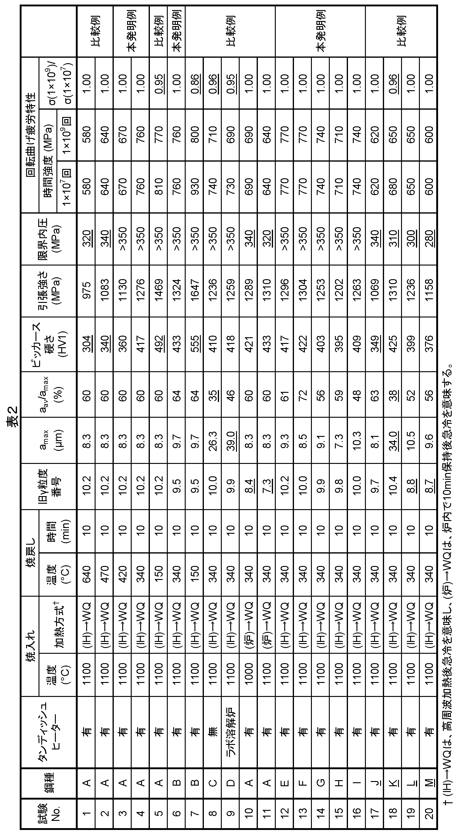
- quenching and tempering treatments were performed under the conditions shown in Table 2, and scale removal and smoothing treatments were performed on the outer and inner surfaces.
- the quenching treatment was performed according to the test No. In Nos. 1 to 9 and 12 to 20, high frequency heating was performed at a temperature rising rate of 100° C./s to 1100° C., and rapid cooling was performed at 50° C./s or more (holding time 5 s or less).
- Nos. 10 and 11 after holding at 1000° C. and 1100° C. for 10 min, respectively, water cooling was performed at 50° C./s or more.
- the tempering treatment was performed under the conditions of holding at 150 to 640° C. for 10 minutes and then allowing to cool. Specific tempering temperatures are also shown in Table 2.
- Non-Patent Document 1 a thin dumbbell-shaped small test piece as shown in Non-Patent Document 1 may be cut out and a tensile test may be performed.
- samples for microstructure observation were taken from each steel pipe, and the cross section perpendicular to the pipe axis direction was mechanically polished. After polishing with emery paper and buff, it was confirmed that the tempered martensite single phase or a mixed structure of tempered martensite and tempered bainite was substantially used by using a Nital etchant. That is, in all the structures, the total area ratio of tempered martensite and tempered bainite was 95% or more.
- test No. 1 Since the former austenite grain size number does not change by tempering, test No. 1 having the same steel type and quenching conditions was used. Test No. 1 to 5 The measured value of No. 4 is the test number. Test Nos. 6 and 7 were tested. The measured value of 6 was used as a representative value.
- the internal pressure fatigue test was carried out by the following procedure. First, each steel pipe was cut into a length of 200 mm, pipe end processing was performed, and an injection pipe test piece for internal pressure fatigue test was obtained. In the fatigue test, one end face of the sample is sealed, the working oil is sealed from the other end face as a pressure medium inside the sample, and the internal pressure of the sealed part takes a sine wave with respect to time in the range from the maximum internal pressure to the minimum 18 MPa. Thus, it is repeatedly changed. The frequency of the internal pressure fluctuation was 8 Hz. As a result of the internal pressure fatigue test, the maximum internal pressure at which breakage (leakage) did not occur even when the number of repetitions reached 10 7 was evaluated as the limit internal pressure.
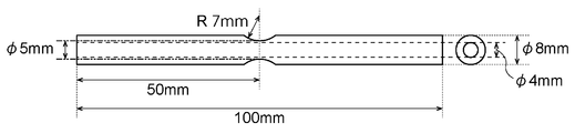
- a test piece having the shape shown in FIG. 1 was manufactured, and a rotary bending fatigue test was conducted in the following procedure. Specifically, a straight tube-shaped sample having a length of 100 mm was cut out, a notch of R7 mm was provided at the center, and the diameter of the notch bottom was 5 mm.
- the rotating bending fatigue test was performed using a cantilever rotating bending fatigue tester. That is, a fatigue test was carried out by a method in which one end of the sample was fixed to the rotating shaft of the motor and the weight was hung at the other end via a bearing.
- test stress was set by multiplying the nominal stress calculated from the weight by the stress concentration factor obtained by actual measurement with a strain gauge.
- the test frequency is 52 Hz. Fatigue tests were conducted with test stresses of several stages, and when fracture or no fracture occurred at 1 ⁇ 10 9 times, it was cut off there.
- the time strength for 1 ⁇ 10 7 times and 1 ⁇ 10 9 times was determined by the following procedure. That is, the lowest test stress (minimum rupture stress) among the data ruptured with a life shorter than the number of time strength repetitions, and the highest test stress (minimum rupture stress) among the data unbroken at the time strength repetition number ( The maximum unbroken stress) was determined. When the minimum breaking stress was lower than the maximum unbreaking stress, the stress of the average value of both was taken, and when the minimum breaking stress was higher than the maximum unbreaking stress, the minimum breaking stress was taken as the time strength. Then, a value obtained by dividing the time strength for 1 ⁇ 10 9 times by the time strength for 1 ⁇ 10 7 times was adopted as an index of the fatigue strength reduction in the ultra-high cycle region.
- test No. satisfying the requirements of the present invention It can be seen that 3, 4, 6 and 12 to 16 have high internal limit pressure and excellent fatigue properties.
- test No. 1, 2, 5, 7 to 11 and 17 to 20 are comparative examples which do not satisfy any of the requirements of the present invention.
- the test No. In Nos. 1 and 2 since the tempering temperature was high and the hardness was lowered, the limit internal pressure was also inferior.
- the test No. In Nos. 5 and 7 the tempering temperature was low, the hardness was excessive, and a large amount of hydrogen trapped in inclusions was present, resulting in deterioration of fatigue characteristics in the ultra-high cycle region.
- test No. In No. 8 the test temperature was not controlled by the tundish heater and the test No. 8 was used.
- No. 9 a laboratory melting furnace was used, and inclusions were not sufficiently removed. Therefore, a max or a av /a max was out of the range, that is, coarse inclusions were present, and hydrogen was trapped therein. As a result, the fatigue characteristics in the ultra-high cycle region deteriorate.
- test No. 17 since the C content was too low, the hardness was low and the internal limit pressure was also inferior.
- the steel pipe for a fuel injection pipe according to the present invention can be suitably used as a fuel injection pipe for automobiles in particular.
Landscapes
- Chemical & Material Sciences (AREA)
- Engineering & Computer Science (AREA)
- Mechanical Engineering (AREA)
- Organic Chemistry (AREA)
- Materials Engineering (AREA)
- Metallurgy (AREA)
- Thermal Sciences (AREA)
- Crystallography & Structural Chemistry (AREA)
- Physics & Mathematics (AREA)
- General Engineering & Computer Science (AREA)
- Manufacturing & Machinery (AREA)
- Combustion & Propulsion (AREA)
- Heat Treatment Of Articles (AREA)
- Fuel-Injection Apparatus (AREA)
- Heat Treatment Of Steel (AREA)
Abstract
Description
前記鋼管の化学組成が、質量%で、
C:0.17~0.27%、
Si:0.05~0.40%、
Mn:0.30~2.00%、
P:0.020%以下、
S:0.0100%以下、
O:0.0040%以下、
Ca:0.0010%以下、
Al:0.005~0.060%、
N:0.0020~0.0080%、
Ti:0.005~0.015%、
Nb:0.015~0.045%、
Cr:0~1.00%、
Mo:0~1.00%、
Cu:0~0.50%、
Ni:0~0.50%、
V:0~0.15%、
残部:Feおよび不純物であり、
前記鋼管の肉厚中央部における金属組織が、焼戻しマルテンサイト、または焼戻しマルテンサイトおよび焼戻しベイナイトを含み、かつ焼戻しマルテンサイトおよび焼戻しベイナイトの合計面積率が95%以上であり、
焼戻しマルテンサイト、または焼戻しマルテンサイトおよび焼戻しベイナイトの旧オーステナイト粒度番号が9.0以上であり、
前記鋼管の肉厚中央部における硬さが、350~460HV1であり、
前記鋼管の長手方向に垂直な断面から、面積が0.4mm2の任意の視野を20か所選択し、各視野において観察される介在物の面積の平方根の最大値をそれぞれan(n=1~20)とした際に、anの最大値amaxが30.0μm以下であり、かつanの平均値aavがamaxの40%以上である、
燃料噴射管用鋼管。
Cr:0.03~1.00%、
Mo:0.03~1.00%、
Cu:0.01~0.50%、
Ni:0.01~0.50%、および
V:0.02~0.15%、
から選択される1種以上を含有する、
上記(1)に記載の燃料噴射管用鋼管。
各元素の限定理由は下記のとおりである。なお、以下の説明において含有量についての「%」は、「質量%」を意味する。
Cは、安価に鋼の強度を高めるのに有効な元素である。所望の引張強さを確保するためにはC含有量を0.17%以上とすることが必要である。しかし、C含有量が0.27%を超えると、加工性の低下を招く。したがって、C含有量は0.17~0.27%とする。C含有量は0.20%以上であるのが好ましい。また、C含有量は0.25%以下であるのが好ましく、0.23%以下であるのがより好ましい。
Siは、脱酸作用を有するだけでなく、鋼の焼入れ性を高めて強度を向上させる作用を有する元素である。これらの効果を確実にするためには、Si含有量を0.05%以上とすることが必要である。しかし、Si含有量が0.40%を超えると、靭性の低下を招く。したがって、Si含有量は0.05~0.40%とする。Si含有量は0.15%以上であるのが好ましく、0.35%以下であるのが好ましい。
Mnは、脱酸作用を有するだけでなく、鋼の焼入れ性を高めて強度と靭性とを向上させるのに有効な元素である。しかし、その含有量が0.30%未満では十分な強度が得られず、一方、2.00%を超えるとMnSの粗大化が生じて、熱間圧延時に展伸し、かえって靭性が低下する。このため、Mn含有量は0.30~2.00%とする。Mn含有量は0.40%以上であるのが好ましく、0.50%以上であるのがより好ましい。また、Mn含有量は1.70%以下であるのが好ましく、1.50%以下であるのがより好ましい。
Pは、不純物として鋼中に不可避的に存在する元素である。その含有量が0.020%を超えると、熱間加工性の低下を招くだけでなく、粒界偏析により靭性を著しく低下させる。したがって、P含有量は、0.020%以下とする必要がある。なお、Pの含有量は、低ければ低いほど望ましく、0.015%以下とするのが好ましく、0.012%以下とするのがより好ましい。しかし、過度の低下は、製造コスト上昇を招くため、その下限は、0.005%とするのが好ましい。
Sは、Pと同様に不純物として鋼中に不可避的に存在する元素である。その含有量が0.0100%を超えると粒界に偏析するとともに、硫化物系の介在物を生成して疲労強度の低下を招きやすい。したがって、S含有量は、0.0100%以下とする必要がある。なお、Sの含有量は、低ければ低いほど望ましく、0.0050%以下とするのが好ましく、0.0035%以下とするのがより好ましい。しかし、過度の低下は、製造コスト上昇を招くため、その下限は、0.0005%とするのが好ましい。
Oは、粗大な酸化物を形成し、それに起因する限界内圧の低下を生じやすくする。このような観点からO含有量は0.0040%以下とする必要がある。なお、Oの含有量は、低ければ低いほど望ましく、0.0035%以下とするのが好ましく、0.0025%以下とするのがより好ましく、0.0015%以下とするのがさらに好ましい。しかし、過度の低下は、製造コスト上昇を招くため、その下限は、0.0005%とするのが好ましい。
Caは、シリケート系介在物(JIS G 0555のグループC)を凝集させる作用があり、Ca含有量が0.0010%を超えると粗大なC系介在物の生成により限界内圧が低下する。したがってCa含有量は0.0010%以下とする。Ca含有量は0.0007%以下とすることが好ましく、0.0003%以下とすることがより好ましい。なお、製鋼精錬に係る設備で長期にわたり全くCa処理を行わなければ、設備のCa汚染を解消することができるため、鋼中のCa含有量を実質的に0%とすることが可能である。
Alは、鋼の脱酸を行う上で有効な元素であり、また鋼の靭性および加工性を高める作用を有する元素である。これらの効果を得るには0.005%以上のAlを含有する必要がある。一方、Al含有量が0.060%を超えると、介在物が発生しやすくなり、特にTiを含有する鋼においては、Ti-Al複合介在物が生じるおそれが高くなる。したがって、Al含有量は0.005~0.060%とする。Al含有量は0.008%以上であるのが好ましく、0.010%以上であるのがより好ましい。また、Al含有量は0.050%以下であるのが好ましく、0.040%以下であるのがより好ましい。なお、本発明において、Al含有量は、酸可溶性Al(sol.Al)の含有量を意味する。
Nは、不純物として鋼中に不可避的に存在する元素である。しかしながら本発明では、TiNのピニング効果(pinning effect)による結晶粒粗大化防止を目的として、0.0020%以上のNを残存させる必要がある。一方、N含有量が0.0080%を超えると大型のTi-Al複合介在物が生じるおそれが高くなる。したがって、N含有量は0.0020~0.0080%とする。N含有量は0.0025%以上であるのが好ましく、0.0027%以上であるのがより好ましい。また、N含有量は0.0065%以下であるのが好ましく、0.0050%以下であるのがより好ましい。
Tiは、TiN等の形で微細に析出することで、結晶粒の粗大化防止に貢献する元素である。その効果を得るためには、Ti含有量を0.005%以上とする必要がある。
Nbは、鋼中で炭化物または炭窒化物として微細に分散し、結晶粒界を強くピン止めすることで、組織の微細化に寄与し、限界内圧を向上させる効果を有する。また、Nbの炭化物または炭窒化物の微細分散により、鋼の靭性が向上する。これらの目的のため、0.015%以上のNbを含有させる必要がある。一方、Nb含有量が0.045%を超えると、炭化物、炭窒化物が粗大化し、かえって靭性が低下する。したがって、Nbの含有量は0.015~0.045%とする。Nb含有量は0.018%以上であるのが好ましく、0.020%以上であるのがより好ましい。また、Nb含有量は0.040%以下であるのが好ましく、0.035%以下であるのがより好ましい。
Crは、焼入れ性および耐摩耗性を向上させる効果を有する元素であるので、必要に応じて含有させてもよい。しかし、Cr含有量が1.00%を超えると靭性および冷間加工性が低下するため、含有させる場合のCr含有量は1.00%以下とする。Cr含有量は0.80%以下であるのが好ましい。なお、上記の効果を得たい場合は、Cr含有量を0.03%以上とすることが好ましく、0.05%以上とすることがより好ましく、0.20%以上とすることがさらに好ましく、0.30%以上とすることがさらに好ましい。
Moは、焼入れ性を向上させ、焼戻し軟化抵抗を高めるため、高強度確保に寄与する元素である。そのため、必要に応じてMoを含有させてもよい。しかし、Mo含有量が1.00%を超えてもその効果は飽和する上に、合金コストが嵩む結果となる。したがって、含有させる場合のMo含有量は1.00%以下とする。Mo含有量は0.45%以下であるのが好ましい。なお、上記の効果を得たい場合は、Mo含有量を0.03%以上とすることが好ましく、0.08%以上とすることがより好ましい。
Cuは、鋼の焼入れ性を高めることで強度および靭性を向上させる効果を有する元素である。そのため、必要に応じてCuを含有させてもよい。しかし、Cu含有量が0.50%を超えてもその効果は飽和する上に、合金コストの上昇を招く結果となる。したがって、含有させる場合のCu含有量は0.50%以下とする。Cu含有量は0.40%以下とするのが好ましく、0.35%以下とするのがより好ましい。なお、上記の効果を得たい場合は、Cu含有量を0.01%以上とすることが好ましく、0.02%以上とすることがより好ましく、0.05%以上とすることがさらに好ましい。
Niは、鋼の焼入れ性を高めることで強度および靭性を向上させる効果を有する元素である。そのため、必要に応じてNiを含有させてもよい。しかし、Ni含有量が0.50%を超えてもその効果は飽和する上に、合金コストの上昇を招く結果となる。したがって、含有させる場合のNi含有量は0.50%以下とする。Ni含有量は0.40%以下とするのが好ましく、0.35%以下とするのがより好ましい。なお、上記の効果を得たい場合は、Ni含有量を0.01%以上とすることが好ましく、0.02%以上とすることがより好ましく、0.05%以上とすることがさらに好ましい。
Vは、焼戻し時に微細な炭化物(VC)として析出して、焼戻し軟化抵抗を高め、高温焼戻しを可能とし、鋼の高強度化および高靭性化に寄与する元素である。そのため、必要に応じてVを含有させてもよい。しかし、V含有量が0.15%を超えるとかえって靭性の低下を招くため含有させる場合のV含有量は0.15%以下とする。V含有量は0.12%以下とするのが好ましく、0.10%以下とするのがより好ましい。なお、上記の効果を得たい場合は、V含有量を0.02%以上とすることが好ましく、0.04%以上とすることがより好ましい。
本発明に係る燃料噴射管用鋼管の肉厚中央部における金属組織は、実質的に焼戻しマルテンサイト組織または焼戻しマルテンサイトと焼戻しベイナイトとの混合組織からなるものである。具体的には、上記金属組織は、焼戻しマルテンサイト、または焼戻しマルテンサイトおよび焼戻しベイナイトを含み、かつ焼戻しマルテンサイトおよび焼戻しベイナイトの合計面積率が95%以上である。
本発明に係る燃料噴射管用鋼管の肉厚中央部における硬さは、350~460HV1である。上記硬さが350HV1未満では、十分な強度および限界内圧を得ることができない。一方、上記硬さが460HV1を超えると、疲労強度が顕著に低下する。なお、「HV1」は、試験力を9.8N(1kgf)として、ビッカース硬さ試験を実施した場合の「硬さ記号」を意味する(JIS Z 2244:2009を参照)。
本発明に係る燃料噴射管用鋼管の寸法については特に制限は設けない。しかしながら、一般的に燃料噴射管は使用時における内部の圧力変動を少なくするために、ある程度の容量が必要となる。そのため、本発明に係る燃料噴射管用鋼管の内径は2.5mm以上であることが望ましく、3.0mm以上であることがより望ましい。また、燃料噴射管は高い内圧に耐える必要があるため、鋼管の肉厚は1.5mm以上であることが望ましく、2.0mm以上であることがより望ましい。一方、鋼管の外径が大きすぎる場合、曲げ加工等が困難になる。そのため、鋼管の外径は20mm以下であることが望ましく、10mm以下であることがより望ましい。
D/d≧1.5 ・・・(i)
但し、上記(i)式中のDは燃料噴射管用鋼管の外径(mm)、dは内径(mm)である。
本発明に係る燃料噴射管用鋼管の製造方法について特に制限はないが、例えば、継目無鋼管から製造する場合、以下の方法で予め介在物を抑制した鋼塊を準備し、その鋼塊からマンネスマン製管等の手法で素管を製造し、冷間加工により所望の寸法形状にした後、熱処理をすることによって、製造することができる。
Ac3(℃)=912-230.5C+31.6Si-20.4Mn-39.8Cu-18.1Ni-14.8Cr+16.8Mo
但し、上記式中の元素記号は、鋼材中に含まれる各元素の含有量(質量%)を表し、含有されない場合には0を代入するものとする。

Claims (3)
- 燃料噴射管用の鋼管であって、
前記鋼管の化学組成が、質量%で、
C:0.17~0.27%、
Si:0.05~0.40%、
Mn:0.30~2.00%、
P:0.020%以下、
S:0.0100%以下、
O:0.0040%以下、
Ca:0.0010%以下、
Al:0.005~0.060%、
N:0.0020~0.0080%、
Ti:0.005~0.015%、
Nb:0.015~0.045%、
Cr:0~1.00%、
Mo:0~1.00%、
Cu:0~0.50%、
Ni:0~0.50%、
V:0~0.15%、
残部:Feおよび不純物であり、
前記鋼管の肉厚中央部における金属組織が、焼戻しマルテンサイト、または焼戻しマルテンサイトおよび焼戻しベイナイトを含み、かつ焼戻しマルテンサイトおよび焼戻しベイナイトの合計面積率が95%以上であり、
焼戻しマルテンサイト、または焼戻しマルテンサイトおよび焼戻しベイナイトの旧オーステナイト粒度番号が9.0以上であり、
前記鋼管の肉厚中央部における硬さが、350~460HV1であり、
前記鋼管の長手方向に垂直な断面から、面積が0.4mm2の任意の視野を20か所選択し、各視野において観察される介在物の面積の平方根の最大値をそれぞれan(n=1~20)とした際に、anの最大値amaxが30.0μm以下であり、かつanの平均値aavがamaxの40%以上である、
燃料噴射管用鋼管。 - 前記鋼管の化学組成が、質量%で、
Cr:0.03~1.00%、
Mo:0.03~1.00%、
Cu:0.01~0.50%、
Ni:0.01~0.50%、および
V:0.02~0.15%、
から選択される1種以上を含有する、
請求項1に記載の燃料噴射管用鋼管。 - 請求項1または請求項2に記載の燃料噴射管用鋼管を用いた燃料噴射管。
Priority Applications (4)
| Application Number | Priority Date | Filing Date | Title |
|---|---|---|---|
| US17/427,864 US12460275B2 (en) | 2019-02-13 | 2020-02-13 | Steel pipe for fuel injection pipe, and fuel injection pipe using same |
| CN202080014397.3A CN113453812B (zh) | 2019-02-13 | 2020-02-13 | 燃料喷射管用钢管及使用其的燃料喷射管 |
| EP20756583.9A EP3925715A4 (en) | 2019-02-13 | 2020-02-13 | STEEL PIPE FOR A FUEL INJECTION PIPE AND FUEL INJECTION PIPE WITH IT |
| JP2020572291A JP7149352B2 (ja) | 2019-02-13 | 2020-02-13 | 燃料噴射管用鋼管およびそれを用いた燃料噴射管 |
Applications Claiming Priority (2)
| Application Number | Priority Date | Filing Date | Title |
|---|---|---|---|
| JP2019023252 | 2019-02-13 | ||
| JP2019-023252 | 2019-02-13 |
Publications (1)
| Publication Number | Publication Date |
|---|---|
| WO2020166637A1 true WO2020166637A1 (ja) | 2020-08-20 |
Family
ID=72045445
Family Applications (1)
| Application Number | Title | Priority Date | Filing Date |
|---|---|---|---|
| PCT/JP2020/005434 Ceased WO2020166637A1 (ja) | 2019-02-13 | 2020-02-13 | 燃料噴射管用鋼管およびそれを用いた燃料噴射管 |
Country Status (5)
| Country | Link |
|---|---|
| US (1) | US12460275B2 (ja) |
| EP (1) | EP3925715A4 (ja) |
| JP (1) | JP7149352B2 (ja) |
| CN (1) | CN113453812B (ja) |
| WO (1) | WO2020166637A1 (ja) |
Cited By (2)
| Publication number | Priority date | Publication date | Assignee | Title |
|---|---|---|---|---|
| WO2022209896A1 (ja) * | 2021-03-30 | 2022-10-06 | Jfeスチール株式会社 | 高圧水素用鋼管、高圧水素用容器および前記鋼管の製造方法 |
| RU2821402C2 (ru) * | 2021-03-30 | 2024-06-24 | ДжФЕ СТИЛ КОРПОРЕЙШН | Стальная труба для водорода высокого давления, сосуд для водорода высокого давления и способ изготовления стальной трубы |
Families Citing this family (2)
| Publication number | Priority date | Publication date | Assignee | Title |
|---|---|---|---|---|
| CN119923487A (zh) * | 2022-09-29 | 2025-05-02 | 杰富意钢铁株式会社 | 耐氢脆化特性优异的管线管用钢管、其制造方法、管线管用钢材及其制造方法 |
| CN117888034B (zh) * | 2024-03-15 | 2024-06-07 | 江苏永钢集团有限公司 | 2000MPa级含钒55SiCr弹簧钢热轧盘条及其生产工艺 |
Citations (9)
| Publication number | Priority date | Publication date | Assignee | Title |
|---|---|---|---|---|
| JPH0957329A (ja) | 1995-08-28 | 1997-03-04 | Nkk Corp | ディーゼルエンジン燃料噴射管用鋼管の製造方法 |
| WO2007119734A1 (ja) | 2006-04-13 | 2007-10-25 | Usui Kokusai Sangyo Kaisha, Ltd. | 燃料噴射管用鋼管 |
| WO2009008281A1 (ja) | 2007-07-10 | 2009-01-15 | Usui Kokusai Sangyo Kaisha, Ltd. | 燃料噴射管用鋼管およびその製造方法 |
| JP2010024503A (ja) * | 2008-07-22 | 2010-02-04 | Sumitomo Metal Ind Ltd | 高強度鋼製粗形品およびその製造方法 |
| JP2010106353A (ja) * | 2008-10-31 | 2010-05-13 | Usui Kokusai Sangyo Kaisha Ltd | 焼入性に優れた高強度鋼製加工品及びその製造方法、並びに高強度かつ耐衝撃特性及び耐内圧疲労特性に優れたディーゼルエンジン用燃料噴射管及びコモンレールの製造方法 |
| JP2011084813A (ja) * | 2009-09-15 | 2011-04-28 | Usui Kokusai Sangyo Kaisha Ltd | 切欠き疲労強度に優れた高強度鋼製加工品及びその製造方法 |
| WO2015129617A1 (ja) | 2014-02-25 | 2015-09-03 | 臼井国際産業株式会社 | 燃料噴射管用鋼管およびそれを用いた燃料噴射管 |
| WO2016038809A1 (ja) * | 2014-09-08 | 2016-03-17 | Jfeスチール株式会社 | 油井用高強度継目無鋼管およびその製造方法 |
| WO2016103538A1 (ja) * | 2014-12-24 | 2016-06-30 | Jfeスチール株式会社 | 油井用高強度継目無鋼管およびその製造方法 |
Family Cites Families (10)
| Publication number | Priority date | Publication date | Assignee | Title |
|---|---|---|---|---|
| US9340847B2 (en) * | 2012-04-10 | 2016-05-17 | Tenaris Connections Limited | Methods of manufacturing steel tubes for drilling rods with improved mechanical properties, and rods made by the same |
| CN105102657B (zh) * | 2013-03-29 | 2017-03-15 | 杰富意钢铁株式会社 | 钢材及氢用容器、以及它们的制造方法 |
| MX372913B (es) * | 2013-07-04 | 2020-04-27 | Nippon Steel Corp | Tubo sin costura para una tubería de conducción utilizada en ambientes ácidos. |
| JP5748032B1 (ja) * | 2013-07-25 | 2015-07-15 | 新日鐵住金株式会社 | ラインパイプ用鋼板及びラインパイプ |
| US10640856B2 (en) * | 2014-09-08 | 2020-05-05 | Jfe Steel Corporation | High-strength seamless steel pipe for oil country tubular goods and method of producing the same |
| MX2017016594A (es) * | 2015-06-17 | 2018-11-09 | Usui Co Ltd | Tuberia de acero para tuberia de inyeccion de combustible y metodo para su produccion. |
| US10487373B2 (en) * | 2015-07-27 | 2019-11-26 | Nippon Steel Corporation | Steel pipe for line pipe and method of manufacturing the same |
| AU2016393486B2 (en) * | 2016-02-16 | 2019-07-18 | Nippon Steel Corporation | Seamless steel pipe and method of manufacturing the same |
| CN106048412B (zh) * | 2016-06-29 | 2018-04-27 | 宝山钢铁股份有限公司 | 一种相变强化冷加工高强度钢、钢管及钢管的制造方法 |
| JP6648646B2 (ja) * | 2016-07-20 | 2020-02-14 | 日本製鉄株式会社 | 低合金鋼材、低合金鋼管および容器、ならびにその容器の製造方法 |
-
2020
- 2020-02-13 EP EP20756583.9A patent/EP3925715A4/en active Pending
- 2020-02-13 CN CN202080014397.3A patent/CN113453812B/zh active Active
- 2020-02-13 WO PCT/JP2020/005434 patent/WO2020166637A1/ja not_active Ceased
- 2020-02-13 US US17/427,864 patent/US12460275B2/en active Active
- 2020-02-13 JP JP2020572291A patent/JP7149352B2/ja active Active
Patent Citations (9)
| Publication number | Priority date | Publication date | Assignee | Title |
|---|---|---|---|---|
| JPH0957329A (ja) | 1995-08-28 | 1997-03-04 | Nkk Corp | ディーゼルエンジン燃料噴射管用鋼管の製造方法 |
| WO2007119734A1 (ja) | 2006-04-13 | 2007-10-25 | Usui Kokusai Sangyo Kaisha, Ltd. | 燃料噴射管用鋼管 |
| WO2009008281A1 (ja) | 2007-07-10 | 2009-01-15 | Usui Kokusai Sangyo Kaisha, Ltd. | 燃料噴射管用鋼管およびその製造方法 |
| JP2010024503A (ja) * | 2008-07-22 | 2010-02-04 | Sumitomo Metal Ind Ltd | 高強度鋼製粗形品およびその製造方法 |
| JP2010106353A (ja) * | 2008-10-31 | 2010-05-13 | Usui Kokusai Sangyo Kaisha Ltd | 焼入性に優れた高強度鋼製加工品及びその製造方法、並びに高強度かつ耐衝撃特性及び耐内圧疲労特性に優れたディーゼルエンジン用燃料噴射管及びコモンレールの製造方法 |
| JP2011084813A (ja) * | 2009-09-15 | 2011-04-28 | Usui Kokusai Sangyo Kaisha Ltd | 切欠き疲労強度に優れた高強度鋼製加工品及びその製造方法 |
| WO2015129617A1 (ja) | 2014-02-25 | 2015-09-03 | 臼井国際産業株式会社 | 燃料噴射管用鋼管およびそれを用いた燃料噴射管 |
| WO2016038809A1 (ja) * | 2014-09-08 | 2016-03-17 | Jfeスチール株式会社 | 油井用高強度継目無鋼管およびその製造方法 |
| WO2016103538A1 (ja) * | 2014-12-24 | 2016-06-30 | Jfeスチール株式会社 | 油井用高強度継目無鋼管およびその製造方法 |
Non-Patent Citations (3)
| Title |
|---|
| EISUKE NAKAYAMAMITSUO MIYAHARAKAZUO OKAMURAHIROKI FUJIMOTOKIYOYUKI FUKUI: "Prediction of Fatigue Strength of Spot-Welded Joints Based on Local Material Strength Properties Measured by Small Specimen", J. SOC, MAT. SCI., JAPAN, vol. 53, no. 10, October 2004 (2004-10-01), pages 1136 - 1142 |
| See also references of EP3925715A4 |
| TATSURO KUNITAKE, HEAT TREATMENT, vol. 41, 2001, pages 164 |
Cited By (4)
| Publication number | Priority date | Publication date | Assignee | Title |
|---|---|---|---|---|
| WO2022209896A1 (ja) * | 2021-03-30 | 2022-10-06 | Jfeスチール株式会社 | 高圧水素用鋼管、高圧水素用容器および前記鋼管の製造方法 |
| JP7226656B1 (ja) * | 2021-03-30 | 2023-02-21 | Jfeスチール株式会社 | 高圧水素用鋼管、高圧水素用容器および前記鋼管の製造方法 |
| RU2821402C2 (ru) * | 2021-03-30 | 2024-06-24 | ДжФЕ СТИЛ КОРПОРЕЙШН | Стальная труба для водорода высокого давления, сосуд для водорода высокого давления и способ изготовления стальной трубы |
| EP4296395A4 (en) * | 2021-03-30 | 2025-07-30 | Jfe Steel Corp | STEEL PIPE FOR HIGH-PRESSURE HYDROGEN, CONTAINER FOR HIGH-PRESSURE HYDROGEN, AND METHOD FOR MANUFACTURING SAID STEEL PIPE |
Also Published As
| Publication number | Publication date |
|---|---|
| US12460275B2 (en) | 2025-11-04 |
| EP3925715A4 (en) | 2023-06-14 |
| US20220112572A1 (en) | 2022-04-14 |
| JP7149352B2 (ja) | 2022-10-06 |
| CN113453812A (zh) | 2021-09-28 |
| EP3925715A1 (en) | 2021-12-22 |
| CN113453812B (zh) | 2023-06-16 |
| JPWO2020166637A1 (ja) | 2021-12-09 |
Similar Documents
| Publication | Publication Date | Title |
|---|---|---|
| CN104204263B (zh) | 冷锻性优异的钢线材或棒钢 | |
| JP6051335B2 (ja) | 燃料噴射管用鋼管およびそれを用いた燃料噴射管 | |
| JP6107437B2 (ja) | 耐硫化物応力腐食割れ性に優れた油井用低合金高強度継目無鋼管の製造方法 | |
| JP6530069B2 (ja) | 燃料噴射管用鋼管およびその製造方法 | |
| JP5761116B2 (ja) | 車輪用鋼 | |
| JP6172391B2 (ja) | 低合金油井用鋼管 | |
| WO2012067237A1 (ja) | 車輪用鋼 | |
| JP6631640B2 (ja) | 肌焼鋼、浸炭部品および肌焼鋼の製造方法 | |
| JP7149352B2 (ja) | 燃料噴射管用鋼管およびそれを用いた燃料噴射管 | |
| CN113423516B (zh) | 燃料喷射管用钢管及使用其的燃料喷射管 | |
| EP3330398B1 (en) | Steel pipe for line pipe and method for manufacturing same | |
| CN107429359A (zh) | 热轧棒线材、部件及热轧棒线材的制造方法 | |
| CN115335544A (zh) | 钢材及渗碳钢部件 | |
| HK1204018B (en) | Steel for vehicle wheel |
Legal Events
| Date | Code | Title | Description |
|---|---|---|---|
| 121 | Ep: the epo has been informed by wipo that ep was designated in this application |
Ref document number: 20756583 Country of ref document: EP Kind code of ref document: A1 |
|
| ENP | Entry into the national phase |
Ref document number: 2020572291 Country of ref document: JP Kind code of ref document: A |
|
| NENP | Non-entry into the national phase |
Ref country code: DE |
|
| ENP | Entry into the national phase |
Ref document number: 2020756583 Country of ref document: EP Effective date: 20210913 |
|
| WWG | Wipo information: grant in national office |
Ref document number: 17427864 Country of ref document: US |