WO2020170569A1 - 自動車用衝突エネルギー吸収部品 - Google Patents
自動車用衝突エネルギー吸収部品 Download PDFInfo
- Publication number
- WO2020170569A1 WO2020170569A1 PCT/JP2019/048694 JP2019048694W WO2020170569A1 WO 2020170569 A1 WO2020170569 A1 WO 2020170569A1 JP 2019048694 W JP2019048694 W JP 2019048694W WO 2020170569 A1 WO2020170569 A1 WO 2020170569A1
- Authority
- WO
- WIPO (PCT)
- Prior art keywords
- resin
- tubular member
- closed cross
- mpa
- collision energy
- Prior art date
- Legal status (The legal status is an assumption and is not a legal conclusion. Google has not performed a legal analysis and makes no representation as to the accuracy of the status listed.)
- Ceased
Links
Images
Classifications
-
- B—PERFORMING OPERATIONS; TRANSPORTING
- B60—VEHICLES IN GENERAL
- B60R—VEHICLES, VEHICLE FITTINGS, OR VEHICLE PARTS, NOT OTHERWISE PROVIDED FOR
- B60R19/00—Wheel guards; Radiator guards, e.g. grilles; Obstruction removers; Fittings damping bouncing force in collisions
- B60R19/02—Bumpers, i.e. impact receiving or absorbing members for protecting vehicles or fending off blows from other vehicles or objects
- B60R19/18—Bumpers, i.e. impact receiving or absorbing members for protecting vehicles or fending off blows from other vehicles or objects characterised by the cross-section; Means within the bumper to absorb impact
-
- B—PERFORMING OPERATIONS; TRANSPORTING
- B62—LAND VEHICLES FOR TRAVELLING OTHERWISE THAN ON RAILS
- B62D—MOTOR VEHICLES; TRAILERS
- B62D21/00—Understructures, i.e. chassis frame on which a vehicle body may be mounted
- B62D21/15—Understructures, i.e. chassis frame on which a vehicle body may be mounted having impact absorbing means, e.g. a frame designed to permanently or temporarily change shape or dimension upon impact with another body
-
- B—PERFORMING OPERATIONS; TRANSPORTING
- B62—LAND VEHICLES FOR TRAVELLING OTHERWISE THAN ON RAILS
- B62D—MOTOR VEHICLES; TRAILERS
- B62D21/00—Understructures, i.e. chassis frame on which a vehicle body may be mounted
- B62D21/15—Understructures, i.e. chassis frame on which a vehicle body may be mounted having impact absorbing means, e.g. a frame designed to permanently or temporarily change shape or dimension upon impact with another body
- B62D21/152—Front or rear frames
-
- B—PERFORMING OPERATIONS; TRANSPORTING
- B60—VEHICLES IN GENERAL
- B60R—VEHICLES, VEHICLE FITTINGS, OR VEHICLE PARTS, NOT OTHERWISE PROVIDED FOR
- B60R19/00—Wheel guards; Radiator guards, e.g. grilles; Obstruction removers; Fittings damping bouncing force in collisions
- B60R19/02—Bumpers, i.e. impact receiving or absorbing members for protecting vehicles or fending off blows from other vehicles or objects
- B60R19/24—Arrangements for mounting bumpers on vehicles
- B60R19/26—Arrangements for mounting bumpers on vehicles comprising yieldable mounting means
- B60R19/34—Arrangements for mounting bumpers on vehicles comprising yieldable mounting means destroyed upon impact, e.g. one-shot type
-
- B—PERFORMING OPERATIONS; TRANSPORTING
- B62—LAND VEHICLES FOR TRAVELLING OTHERWISE THAN ON RAILS
- B62D—MOTOR VEHICLES; TRAILERS
- B62D29/00—Superstructures, understructures, or sub-units thereof, characterised by the material thereof
- B62D29/001—Superstructures, understructures, or sub-units thereof, characterised by the material thereof characterised by combining metal and synthetic material
-
- B—PERFORMING OPERATIONS; TRANSPORTING
- B62—LAND VEHICLES FOR TRAVELLING OTHERWISE THAN ON RAILS
- B62D—MOTOR VEHICLES; TRAILERS
- B62D29/00—Superstructures, understructures, or sub-units thereof, characterised by the material thereof
- B62D29/001—Superstructures, understructures, or sub-units thereof, characterised by the material thereof characterised by combining metal and synthetic material
- B62D29/002—Superstructures, understructures, or sub-units thereof, characterised by the material thereof characterised by combining metal and synthetic material a foamable synthetic material or metal being added in situ
-
- B—PERFORMING OPERATIONS; TRANSPORTING
- B62—LAND VEHICLES FOR TRAVELLING OTHERWISE THAN ON RAILS
- B62D—MOTOR VEHICLES; TRAILERS
- B62D25/00—Superstructure or monocoque structure sub-units; Parts or details thereof not otherwise provided for
Definitions
- the present invention relates to a crashworthiness energy absorption part for automobile, and particularly, when a crashworthiness load is input from the front or rear of a vehicle body, axial crush deformation occurs in the longitudinal direction.
- the present invention relates to a collision energy absorbing component for an automobile, which absorbs collision energy.
- Patent Document 1 a top-portion direction of a hat-shaped cross section part such as a side sill, a floor member, and a pillar is aligned with a flange ( Bending strength of the automobile structural member with a minimum weight increase by filling the inside with a foam filler in the structure of the automobile with a structure in which a closed space is formed by overlapping ,
- the technology to improve the torsional rigidity and the rigidity and collision safety of the vehicle body has been disclosed.
- Patent Document 2 when a high-rigidity foam is filled into an internal space of a closed cross-section structure such as a pillar in which a hat cross-section component is opposed and a flange portion is aligned, the high-rigidity foam is filled and foamed.
- the foam is fixed by compressive counterforce to improve vibration isolation performance that suppresses transmission of vibration sound, and at the same time, strength, rigidity and impact energy absorption.
- Patent Document 1 and Patent Document 2 by filling a foam filler or foam inside the automobile parts, the strength of the automobile parts against bending deformation and the bending due to collision It is said that it is possible to improve the collision energy absorption of deformation and the rigidity against torsion deformation (torsional deformation), and it is possible to suppress the deformation of the automobile parts.
- bellows are generated when a collision load is input from the front or the rear of the vehicle and the shaft is crushed.
- the impact energy absorption performance is There was a problem that it was difficult to improve.
- An object of the present invention is to provide a collision energy absorbing component for an automobile capable of improving the collision energy absorbing effect.
- a vehicle collision energy absorbing component is provided in a front portion or a rear portion of a vehicle body, and axially collapses to absorb the collision energy when a collision load is input from the front or rear of the vehicle body. It is made of a steel sheet having a tensile strength of 590 MPa class (MPa-class) or more and 1180 MPa class or less, and a top plate part and a pair of vertical wall parts (side wall) that follow it. a tubular member having a portion) and a steel plate having a lower tensile strength than that of the tubular member. The tubular member is arranged inside the tubular member so as to straddle the top plate portion and both ends thereof.
- Part is joined to the inner surface of the pair of vertical wall parts, and a closed cross-section space forming wall member that forms a closed cross-section space with a part of the peripheral wall part of the tubular member; And a resin filled in the space, which comprises a rubber-modified epoxy resin and a curing agent, and has a tensile elongation at break.
- the adhesive strength (adhesive strength) of the tubular member and the wall member for forming the closed cross section is 12 MPa or more
- the compression nominal stress at 10% of compression nominal strain is 6 MPa or more. Is.
- a vehicle collision energy absorbing component is provided at a front portion or a rear portion of a vehicle body and axially collapses to absorb the collision energy when a collision load is input from the front or rear of the vehicle body.
- Which has a tensile strength of 590 MPa or more and 1180 MPa or less formed of a steel sheet, a tubular member having a top plate portion and a pair of vertical wall portions following the top plate portion, and a tensile strength higher than that of the tubular member.
- the tubular member It is formed of a low steel plate, is disposed so as to straddle the top plate portion inside the tubular member, and both ends are joined to the inner surfaces of the pair of vertical wall portions, and the peripheral wall portion of the tubular member is It has a closed cross-section space forming wall member that forms a closed cross-section space between itself and a part, and a resin filled in the closed cross-section space, the resin comprising a rubber-modified epoxy resin, and tensile rupture.
- the elongation is 80% or more
- the adhesive strength between the tubular member and the closed-section space forming wall member is 12 MPa or more
- the compression nominal stress at a compression nominal strain of 10% is 6 MPa or more.
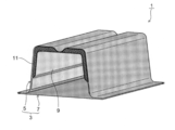
- FIG. 1 is an explanatory diagram illustrating a configuration of a vehicle collision energy absorbing component according to an embodiment of the present invention.
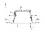
- FIG. 2 is a cross-sectional view of the collision energy absorbing component for automobiles according to the present embodiment.
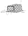
- FIG. 3 is a diagram illustrating a shaft crushing test method for a collision energy absorbing component for automobiles in an example.
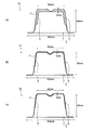
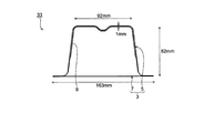
- FIG. 4 is a diagram showing the structure of a test specimen (test specimen) used in the axial crush test in Examples (invention example).
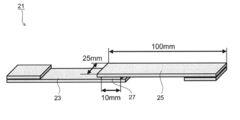
- FIG. 5 is a figure explaining the measuring method of adhesive strength in an Example.
- FIG. 6 is a diagram showing the structure of a test body used in the axial crush test in the examples (comparative example).
- FIG. 1 is an explanatory diagram illustrating a configuration of a vehicle collision energy absorbing component according to an embodiment of the present invention.
- FIG. 2 is a cross-sectional view of the collision energy absorbing component for automobiles according to the present embodiment.
- FIG. 3 is a diagram
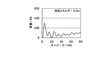
- FIG. 7 shows the measurement results of a collision load and a shaft crush deformation volume (stroke) when a shaft crush test was performed using a vehicle collision energy absorbing component according to a comparative example as a test body in the example. It is a figure.
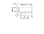
- FIG. 8 is a diagram showing measurement results of a collision load and a shaft crush deformation amount (stroke) when a shaft crush test is performed by using the automobile collision energy absorbing component according to the invention example as a test body in the example.
- FIGS. 1 and 2 A collision energy absorbing component for a vehicle according to an embodiment of the present invention will be described below with reference to FIGS. 1 and 2.
- elements having substantially the same functions and configurations are designated by the same reference numerals, and duplicate description will be omitted.
- a collision energy absorbing component 1 for an automobile has a tubular member 3 composed of outer parts 5 and inner parts 7, Between the outer part 5 which is provided in the front part or the rear part and absorbs the collision energy when a collision load is input from the front or the rear of the vehicle body and which is a part of the peripheral wall part of the tubular member 3. Further, a closed cross section space forming wall member 9 for forming a closed cross section space and a resin 11 filling the cross section of the closed cross section space are provided.
- the tubular member 3 has a top plate portion 5a and a pair of vertical wall portions 5b following the top wall portion 5a that absorb the collision energy by axially crushing, and as shown in FIG. 2, the top plate portion 5a and the vertical wall portion 5b.
- the flange portion 5c of the outer component 5 having a hat cross-sectional shape including the portion 5b and the flange portion 5c is joined to both end portions of the flat inner component 7 to form a tubular shape.
- Both the outer part 5 and the inner part 7 that form the tubular member 3 are made of steel plates having a tensile strength of 590 MPa class to 1180 MPa class.
- the types of steel sheets include cold rolled steel sheet, hot rolled steel sheet, zinc-based coating steel sheet, and zinc alloy coating steel sheet (zinc alloy). Examples include coating steel sheet) and aluminum alloy-based steel sheet (alluminum alloy coating steel sheet).
- the tubular member 3 is provided at the front and rear ends of the vehicle body skeleton and front side members that extend in the vehicle front-rear direction and form a part of the vehicle body skeleton at the left and right positions of the vehicle body front portion. It is used for an automobile part having a closed cross-section structure such as a crash box, and the automobile part is arranged on the vehicle body so that the axial direction (longitudinal direction) of the tubular member 3 coincides with the front-back direction of the vehicle body.
- the closed cross-section space forming wall member 9 is made of a steel plate having a lower tensile strength than the tubular member 3, and as shown in FIG. 2, the outer component 5 and the inner component 7 which are inside the tubular member 3 are formed.
- a closed cross-section space is formed between the top plate portion 5a and the vertical wall portion 5b of the outer component 5, which is a part of the peripheral wall portion of the strip-shaped member 3.
- the both ends of the closed cross-section space forming wall member 9 and the vertical wall portion 5b are joined by, for example, spot welding. Furthermore, the closed cross-section space formed between the closed cross-section space forming wall member 9 and the outer component 5 is a closed cross-section whose cross-sectional shape in the direction intersecting the axial direction of the tubular member 3 shown in FIG.
- the closed cross section means a space formed continuously along the axial direction of the tubular member 3.
- the resin 11 is filled in the closed cross section space formed between the closed cross section space forming wall member 9 and the outer component 5.
- the resin 11 includes a rubber-modified epoxy resin and a curing agent, and by performing a heat treatment at a predetermined temperature and time, the resin 11 has an adhesive capacity. It can be bonded to the outer component 5 and the closed cross-section space forming wall member 9. Furthermore, the resin 11 has a tensile elongation at break of 80% or more, an adhesive strength with the tubular member 3 and the closed cross-section space forming wall member 12 of 12 MPa or more, and a compression nominal stress at a compression nominal strain of 10% of 6 MPa or more. ). All of these physical properties are values after the heat treatment of the resin 11.
- the tensile elongation at break, adhesive strength, and nominal compressive stress may be values determined by the following methods.
- the reasons for defining the type and physical properties of the resin 11 in the automobile collision energy absorbing component 1 according to the present embodiment as described above are as follows. First, since the resin 11 contains a rubber-modified epoxy resin and a curing agent, when the collision load is input to the tubular member 3 and the shaft is collapsed and deformed into a bellows shape, the resin 11 is heated and cured by a heat treatment, By adhering the tubular member 3 and the closed cross-section space forming wall member 9 with an adhesive strength of 12 MPa or more, the resin 11 can be deformed following the deformation of the tubular member 3.
- the resin 11 separates from the tubular member 3 and the closed cross-section space forming wall member 9 in the axial crushing process of the tubular member 3, and the buckling resistance and deformation resistance are reduced. Can be prevented.
- the nominal compression stress at a nominal compression strain of 10% is 6 MPa or more, even if the tubular member 3 is deformed into a bellows shape during the axial crushing process, sufficient yield strength (yield strength) is maintained so that the resin 11 itself does not collapse and break. ) Can be included.
- the types and compositions of the rubber-modified epoxy resin and the curing agent, and further the temperature and time of the heat treatment may be adjusted appropriately so that the tensile elongation at break, the adhesive strength, and the nominal compression stress of the resin 11 fall within the above ranges. Good.
- polyamine (polyamine) (aliphatic polyamine, aromatic amine, aromatic polyamine, polyamidoamine), acid anhydride (acid) anhydride curing agent, phenol-based curing agent, thiol-based curing agent, latent curing agent dicyandiamide, imidazole compound, ketimine
- the resin 11 is removed from the tubular member 3 and the closed cross-section space forming wall member 9 in the process in which the collision load is input to the tubular member 3 and axially collapses.
- the buckling resistance can be improved without deviation, and further, the buckling can be repeatedly generated in the tubular member 3 in a bellows shape without lowering the deformation resistance of the tubular member 3, thus improving the absorption of collision energy. Can be made.
- the resin 11 was composed of a rubber-modified epoxy resin and a curing agent after being heat-treated. However, depending on the amount of curing agent filled in the closed cross section space formed between the closed cross section space forming wall member 9 and the outer part 5, heating at a predetermined temperature and time In some cases, the curing agent does not remain or is not detected in the resin 11 after processing.
- the resin 11 after heat treatment does not contain a curing agent or is not detected, and heat treatment is performed at a predetermined temperature and time.
- the resin 11 itself may be bonded to the outer component 5 and the closed cross-section space forming wall member 9 by performing the above.
- the physical properties thereof are such that the tensile elongation at break is 80% or more, adhesion with the tubular member 3 and the closed cross-section space forming wall member 9
- the strength is 12 MPa or more
- the compression nominal stress at a compression nominal strain of 10% is 6 MPa or more.
- the resin 11 containing the rubber-modified epoxy resin and containing no curing agent or not detected is within the range of the above physical properties, the resin 11 is tubular in the process of inputting a collision load into the tubular member 3 and axially crushing.
- the buckling resistance is improved without deviating from the member 3 and the closed cross-section space forming wall member 9, and furthermore, the buckling is repeatedly generated in the tubular member 3 in a bellows shape without lowering the deformation resistance of the tubular member 3. It is possible to improve the absorption of collision energy.
- the experiment is to perform a shaft crush test using the automobile collision energy absorbing component according to the present invention as a test body.
- the shaft crush test is performed at a test speed of 17.8 m/in the axial direction of the test body 31, as shown in FIG.
- Load-stroke indicating the relationship between the load and the amount of axial crush deformation (stroke) when the load is input in s and the length of the test body (axial length L 0 of the test body 31) is axially crush deformed from 200 mm to 120 mm by 80 mm
- the curve was measured and the deformed state was photographed with a high-speed camera. Further, the absorbed energy at a stroke of 0 to 80 mm was obtained from the measured load-stroke curve.
- FIG. 4 shows the structure and shape of the test body 31 as an example of the invention.
- the invention example is one in which a shaft crush test was performed using the automobile collision energy absorbing component 1 (FIGS. 1 and 2) according to the embodiment of the present invention described above as a test body 31.
- the test body 31 has a tubular member 3 in which the outer part 5 and the inner part 7 are joined by spot welding, and a closed cross-section space is formed between the outer part 5 and the closed cross-section space forming wall member 9, The resin 11 is filled in the entire area of the closed cross section space.
- the height of the gap between the outer part 5 and the wall member 9 for forming the closed cross-section space was set to 1 mm, 3 mm, and 8 mm (FIGS. 4A to 4C).
- a steel plate having a tensile strength of 590 MPa class to 1180 MPa class and a plate thickness of 1.2 mm or 1.4 mm was used, and for the inner part 7, a steel plate having a tensile strength of 590 MPa class and a plate thickness of 1.2 mm was used.
- a steel plate having a tensile strength of 270 MPa and a plate thickness of 0.5 mm was used for the closed cross-section space forming wall member 9.
- the resin 11 is a rubber-modified epoxy resin and a curing agent which are heat-treated at a predetermined heating temperature and a predetermined heating time.
- a predetermined heating temperature and a predetermined heating time within the scope of the present invention.
- the tensile elongation at break, the adhesive strength, and the compressive nominal stress were obtained by separately performing the following test methods.
- the adherend 23 and the adherend 25 are steel plates (SPCC) having a width of 25 mm, a thickness of 1.6 mm, and a length of 100 mm, and an adhesive portion (width of 25 mm, length of 10 mm).
- An uncured resin 27 was placed on the test piece 21, and the test piece 21 was heat-cured under the condition of holding at 180° C. for 20 minutes with the thickness adjusted to 0.15 mm.
- the test piece 21 was subjected to a tensile test at a pulling speed of 5 mm/min until the adherend 23 or the adherend 25 and the resin 27 were broken, and the load at the time of breaking was measured. Then, the value obtained by dividing the load at break by the area of the bonded portion (bonded area: width 25 mm x length 10 mm) was taken as the shear adhesive strength.
- ⁇ Compression nominal stress> The gap between the two steel plates was adjusted to 3 mm, uncured resin was placed between them, heat cured under the condition of 180°C x 20 minutes holding, the steel plates were peeled off, and a plate-shaped resin test piece with a thickness of 3 mm was prepared. .. Then, a test piece was obtained by cutting the flat resin test piece into a cylindrical shape having a diameter of 20 mm. Then, a circular surface having a diameter of 20 mm in the test piece was used as a compression surface, and the load when compressed to a nominal strain of 10% at a test speed of 2 mm/min, the value obtained by dividing the cross-sectional area of the initial test piece by the nominal stress And
- test body 33 (FIG. 6) having the same shape as the tubular member 3 and the closed cross-section space forming wall member 9 of the invention example and not filled with resin was used
- a shaft crush test was conducted in the same manner as in the invention example, except that the test piece 31 having the same shape as that of the example had a physical property of the resin 11 outside the range of the present invention as a comparative example.
- Table 1 shows the conditions of the structures of the test samples used as the invention examples and comparative examples, the type of resin, the tensile elongation at break, the adhesive strength, and the compression nominal stress at a compression nominal strain of 10%.
- Comparative Examples 1 to 4 use the test body 33 not filled with resin
- Comparative Examples 5 to 7 use epoxy or urethane as the type of the resin 11, and the tensile elongation at break, At least one of the adhesive strength and the compressive nominal stress is outside the scope of the present invention, and the test body 31 is used.
- FIG. 7 and 8 show the measurement results of the load-stroke curve when the axial crush test was performed using the test body 33 according to Comparative Example 1 and the test body 31 according to Invention Example 1, respectively.
- Show. 7 and 8 are load-stroke curves in which the horizontal axis represents the stroke (mm) that represents the amount of deformation in the axial direction of the test body from the start of the collision, and the vertical axis represents the load (kN) input to the test body.
- the absorbed energy shown in the graph is the amount of collision energy absorbed when the stroke is 0 to 80 mm.
- Comparative Example 1 shown in FIG. 7 is the result of the test body 33 (FIG. 6) not filled with the resin, and the load input to the test body 33 shows the maximum value (about 300 kN) immediately after the start of input, and thereafter.
- the value of the load fluctuated with the buckling of the peripheral wall portion of the tubular member 3.
- the absorbed energy at the end of the test when the stroke reached 80 mm was 6.5 kJ.
- the resin 11 is filled between the outer component 5 and the closed cross-section space forming wall member 9, and the tensile breaking elongation, adhesive strength and compression nominal stress thereof are within the scope of the present invention.
- the buckling strength increases in the axial crushing process, the deformation resistance increases without peeling the resin 11, and a bellows-like compression deformation occurs, improving the absorption of collision energy. I know what I did.
- the weight of the test body in Table 1 is the total weight of the outer part 5, the inner part 7, the closed cross-section space forming wall member 9 and the resin 11 in the test body 31 filled with the resin 11.
- the test body 33 not filled with resin it is the sum of the weights of the outer part 5, the inner part 7, and the closed cross-section space forming wall member 9.
- Invention Example 2 uses a test body 31 (FIG. 4(c)) in which the thickness of the resin 11 is 1 mm, which is smaller than that of Invention Example 1.
- the weight of the test body in Inventive Example 2 was 1.12 kg, which was lighter than that in Inventive Example 1.
- Inventive Example 3 uses a test body 31 (FIG. 4C) in which the steel plate used for the outer part 5 has a tensile strength of 1180 MPa and the resin 11 has a thickness of 1 mm.
- the weight of the test body in Inventive Example 3 was 1.13 kg, which was lighter than that in Inventive Example 1.
- Inventive Example 4 uses a test body 31 (FIG. 4B) in which the steel plate used for the outer part 5 has a tensile strength of 590 MPa and the resin 11 has a thickness of 3 mm.
- the weight of the test body in Inventive Example 4 was 1.19 kg, which was lighter than that in Inventive Example 1.
- Inventive Example 5 uses a test body 31 (FIG. 4A) in which the steel plate used for the outer part 5 has a tensile strength of 590 MPa and the resin 11 has a thickness of 8 mm.
- the absorbed energy in Inventive Example 5 was 13.1 kJ, which was a significant improvement over the absorbed energy of 6.5 kJ in Comparative Example 1.
- the absorbed energy in Example 5 is significantly large. Improved.
- Inventive Example 6 uses a test body 31 (FIG. 4C) in which the tensile strength of the steel sheet used for the outer part 5 is 1180 MPa and the thickness of the resin 11 is 1 mm.
- the weight of the test body in Inventive Example 6 was 1.12 kg, which was lighter than that in Inventive Example 1.
- Inventive Example 7 uses the test piece 31 (FIG. 4B) in which the steel plate used for the outer component 5 has a tensile strength of 590 MPa and the resin 11 has a thickness of 3 mm.
- the weight of the test piece in Inventive Example 7 was 1.19 kg, which was lighter than that in Inventive Example 1.
- Comparative Example 1 the test body 33 (FIG. 6) not filled with the resin was used, and the weight of the test body was 1.06 kg.
- the absorbed energy was 6.5 kJ, and the absorbed energy per unit weight was 6.1 kJ/kg, as shown in FIG.
- Comparative Example 2 was a test piece 33 having the same shape as that of Comparative Example 1, except that a steel plate having a plate thickness of 1.4 mm was used for the outer part 5, and the weight of the test piece was 1.17 kg.
- the absorbed energy in Comparative Example 2 was 7.0 kJ and the absorbed energy per unit weight was 6.0 kJ/kg. Although the absorbed energy was higher than that in Comparative Example 1, it did not reach that of Invention Examples 1 to 7.
- Comparative Example 3 a steel plate having a tensile strength of 980 MPa grade was used for the outer part 5 in the test piece 33 having the same shape as that of Comparative Example 1, and the weight of the test piece was 1.06 kg.
- the absorbed energy in Comparative Example 3 was 8.1 kJ, and the absorbed energy per unit weight was 7.6 kJ/kg, which were both higher than those in Comparative Example 1, but not as high as those of Inventive Examples 1 to 7.
- Comparative Example 4 a steel plate having a tensile strength of 1180 MPa was used for the outer part 5 of the test piece 33 having the same shape as that of Comparative Example 1, and the weight of the test piece was 1.07 kg.
- the absorbed energy in Comparative Example 4 was 8.5 kJ and the absorbed energy per unit weight was 7.9 kJ/kg, both of which were higher than those of Comparative Example 1, but were not as high as those of Inventive Examples 1 to 7.
- Comparative Example 5 Comparative Example 6 and Comparative Example 7 have the same shape as the test body 31 according to Inventive Example 2, but at least one of the type of resin or the tensile elongation at break, adhesive strength and compressive nominal stress of the resin.
- the absorbed energy and the absorbed energy per unit weight in Comparative Example 5, Comparative Example 6 and Comparative Example 7 did not reach those of Inventive Examples 1 to 7.
- the collision energy absorbing component for an automobile can improve the collision energy absorbing performance when the collision load is input in the axial direction and the shaft is crushed.
- ADVANTAGE OF THE INVENTION when a collision load is input from the front or rear of a vehicle body such as a front side member or a crash box and axially crushes in a bellows-like manner, the effect of absorbing collision energy can be improved.
- An energy absorbing component can be provided.
Landscapes
- Engineering & Computer Science (AREA)
- Mechanical Engineering (AREA)
- Chemical & Material Sciences (AREA)
- Combustion & Propulsion (AREA)
- Transportation (AREA)
- Architecture (AREA)
- Structural Engineering (AREA)
- Body Structure For Vehicles (AREA)
- Vibration Dampers (AREA)
Abstract
Description
筒状部材3は、軸圧壊して衝突エネルギーを吸収し、天板部5aとこれに続く一対の縦壁部5bを有するものであり、図2に示すように、天板部5aと縦壁部5bとフランジ部5cとからなるハット断面形状のアウタ部品5のフランジ部5cと、平板状のインナ部品7の両側端部とが接合して筒状に形成されたものである。
閉断面空間形成壁部材9は、筒状部材3よりも引張強度の低い鋼板から形成されてなり、図2に示すように、筒状部材3の内側であるアウタ部品5とインナ部品7との間に天板部5aを跨ぐように配設された略コ字断面形状(U-shaped cross section)の部材であり、その両端部がアウタ部品5の一対の縦壁部5bに接合され、筒状部材3の周壁部の一部であるアウタ部品5の天板部5a及び縦壁部5bとの間に閉断面空間を形成するものである。
樹脂11は、閉断面空間形成壁部材9とアウタ部品5との間に形成された閉断面空間に充填されたものである。
所定の間隙に調整した2枚の鋼板の間に未硬化の樹脂を入れ、所定の条件で加熱硬化させ、鋼板を剥がして平板状樹脂を作製し、該平板状樹脂を所定の形状に加工して試験片を作製する。次いで、所定の引張速度で樹脂が破断するまで引張試験を行い、樹脂破断時の標線間伸び量を測定する。そして、該測定した樹脂破断時の標線間伸び量を初期の標線間距離で除して百分率表示した値を引張破断伸びとする。
所定の間隙に調整した2枚の鋼板の間に未硬化の樹脂を入れ、所定の条件で加熱硬化させ、試験片を作製する。次いで、該試験片を所定の引張速度で引張試験を行い、鋼板と樹脂とが破断した時の荷重(load)を測定する。そして、該測定した破断時の荷重を鋼板と樹脂との接着面積で除した値(=せん断接着強度(shearing adhesive strength))を接着強度(adhesive strength)とする。
所定の間隙に調整した2枚の鋼板の間に未硬化の樹脂を入れ、所定の条件で加熱硬化させ、鋼板を剥がして平板状樹脂を作製する。次いで、該平板状樹脂を円柱状に切り出して試験片を作製する。そして、当該試験片における円形状面を圧縮面とし、所定の試験速度で公称歪10%まで圧縮した時の荷重について、初期の試験片の断面績で除した値を圧縮公称応力する。
2枚の鋼板の間隙を2mmに調整し、その間に未硬化の樹脂を入れ、180℃×20分保持の条件で加熱硬化させ、鋼板を剥がして厚さ2mmの平板状樹脂を作製した。続いて、当該平板状樹脂をダンベル形状(dumbbell shape)(JIS6号ダンベル)に加工して試験片を作製し、引張速度(tensile speed)2mm/minで樹脂が破断するまで引張試験(tensile test)を行い、樹脂破断時の標線間伸び量(elongation between marked lines)を測定した。そして、該測定した樹脂破断時の標線間伸び量を初期の標線間距離(=20mm)で除した値を百分率表示し、引張破断伸びとした。
図5に示すように、被着体23及び被着体25は、幅25mm、厚さ1.6mm、長さ100mmの鋼板(SPCC)とし、接着部(adhesive portion)(幅25mm、長さ10mm)に未硬化の樹脂27を設置し、厚み0.15mmに調整した状態で、180℃×20分保持の条件で加熱硬化したものを試験片21とした。次いで、試験片21を引張速度5mm/minで被着体(adherend)23又は被着体25と樹脂27とが破断するまでの引張試験を行い、破断時の荷重を測定した。そして、破断時の荷重を接着部の面積(接着面積:幅25mm×長さ10mm)で除した値をせん断接着強度とした。
2枚の鋼板の間隙を3mmに調整し、その間に未硬化の樹脂を入れ、180℃×20分保持の条件で加熱硬化させ、鋼板を剥がして厚さ3mmの平板状樹脂試験片を作製した。次いで、該平板状樹脂試験片から直径20mmの円柱状に切り出したものを試験片とした。そして、当該試験片における直径20mmの円形状面を圧縮面とし、試験速度2mm/minで公称歪10%まで圧縮した時の荷重について、初期の試験片の断面績で除した値を圧縮公称応力とした。

3 筒状部材
5 アウタ部品
5a 天板部
5b 縦壁部
5c フランジ部
7 インナ部品
9 閉断面空間形成壁部材
11 樹脂
21 試験片
23 被着体
25 被着体
27 樹脂
31 試験体
33 試験体
Claims (2)
- 車体の前部又は後部に設けられ、該車体の前方又は後方から衝突荷重が入力した際に軸圧壊して衝突エネルギーを吸収する自動車用衝突エネルギー吸収部品であって、
引張強度が590MPa級以上1180MPa級以下の鋼板から形成されてなり、天板部とこれに続く一対の縦壁部を有する筒状部材と、
該筒状部材よりも引張強度の低い鋼板から形成されてなり、前記筒状部材の内側に前記天板部を跨ぐように配設されて両端部が前記一対の縦壁部の内面に接合され、該筒状部材の周壁部の一部との間に閉断面空間を形成する閉断面空間形成壁部材と、
前記閉断面空間に充填された樹脂と、を有し、
該樹脂は、ゴム変性エポキシ樹脂と硬化剤とを含んでなり、
引張破断伸びが80%以上、前記筒状部材及び前記閉断面空間形成壁部材との接着強度が12MPa以上、圧縮公称歪10%における圧縮公称応力が6MPa以上である、自動車用衝突エネルギー吸収部品。 - 車体の前部又は後部に設けられ、該車体の前方又は後方から衝突荷重が入力した際に軸圧壊して衝突エネルギーを吸収する自動車用衝突エネルギー吸収部品であって、
引張強度が590MPa級以上1180MPa級以下の鋼板から形成されてなり、天板部とこれに続く一対の縦壁部を有する筒状部材と、
該筒状部材よりも引張強度の低い鋼板から形成されてなり、前記筒状部材の内側に前記天板部を跨ぐように配設されて両端部が前記一対の縦壁部の内面に接合され、該筒状部材の周壁部の一部との間に閉断面空間を形成する閉断面空間形成壁部材と、
前記閉断面空間に充填された樹脂と、を有し、
該樹脂は、ゴム変性エポキシ樹脂を含んでなり、
引張破断伸びが80%以上、前記筒状部材及び前記閉断面空間形成壁部材との接着強度が12MPa以上、圧縮公称歪10%における圧縮公称応力が6MPa以上である、自動車用衝突エネルギー吸収部品。
Priority Applications (5)
| Application Number | Priority Date | Filing Date | Title |
|---|---|---|---|
| KR1020217025348A KR102547461B1 (ko) | 2019-02-22 | 2019-12-12 | 자동차용 충돌 에너지 흡수 부품 |
| US17/429,101 US11975762B2 (en) | 2019-02-22 | 2019-12-12 | Crashworthiness energy absorption parts for automotive |
| CN201980091628.8A CN113423615B (zh) | 2019-02-22 | 2019-12-12 | 汽车用碰撞能量吸收部件 |
| MX2021010052A MX2021010052A (es) | 2019-02-22 | 2019-12-12 | Partes de absorcion de energia de resistencia a choques para automovil. |
| EP19916530.9A EP3929037B1 (en) | 2019-02-22 | 2019-12-12 | Collision energy absorption component for automobiles |
Applications Claiming Priority (4)
| Application Number | Priority Date | Filing Date | Title |
|---|---|---|---|
| JP2019030116 | 2019-02-22 | ||
| JP2019-030116 | 2019-02-22 | ||
| JP2019-190730 | 2019-10-18 | ||
| JP2019190730A JP7026088B2 (ja) | 2019-02-22 | 2019-10-18 | 自動車用衝突エネルギー吸収部品 |
Publications (1)
| Publication Number | Publication Date |
|---|---|
| WO2020170569A1 true WO2020170569A1 (ja) | 2020-08-27 |
Family
ID=72145072
Family Applications (1)
| Application Number | Title | Priority Date | Filing Date |
|---|---|---|---|
| PCT/JP2019/048694 Ceased WO2020170569A1 (ja) | 2019-02-22 | 2019-12-12 | 自動車用衝突エネルギー吸収部品 |
Country Status (4)
| Country | Link |
|---|---|
| US (1) | US11975762B2 (ja) |
| EP (1) | EP3929037B1 (ja) |
| MX (1) | MX2021010052A (ja) |
| WO (1) | WO2020170569A1 (ja) |
Cited By (1)
| Publication number | Priority date | Publication date | Assignee | Title |
|---|---|---|---|---|
| WO2021256035A1 (ja) * | 2020-06-17 | 2021-12-23 | Jfeスチール株式会社 | 自動車用衝突エネルギー吸収部品 |
Families Citing this family (3)
| Publication number | Priority date | Publication date | Assignee | Title |
|---|---|---|---|---|
| WO2019198729A1 (ja) * | 2018-04-09 | 2019-10-17 | 日本製鉄株式会社 | 自動車構造部材 |
| JP6950871B2 (ja) * | 2019-01-23 | 2021-10-13 | Jfeスチール株式会社 | 車体骨格部品 |
| CN116056956B (zh) * | 2020-07-31 | 2026-02-24 | 日本制铁株式会社 | 汽车车身构造部件 |
Citations (7)
| Publication number | Priority date | Publication date | Assignee | Title |
|---|---|---|---|---|
| WO1999010168A1 (fr) * | 1997-08-21 | 1999-03-04 | Toray Industries, Inc. | Element structural en metal leger/plastique renforce par fibres de carbone |
| JP2000318075A (ja) | 1999-05-12 | 2000-11-21 | Tokai Rubber Ind Ltd | 高剛性発泡体充填構造体 |
| WO2004108807A1 (ja) * | 2003-06-04 | 2004-12-16 | Sunstar Giken Kabushiki Kaisha | ペースト状加熱発泡充填材組成物および車体部材閉断面の充填遮音方法 |
| JP2006240134A (ja) | 2005-03-04 | 2006-09-14 | Nissan Motor Co Ltd | 自動車用構造部材及びその製造方法 |
| JP2011529817A (ja) * | 2008-07-29 | 2011-12-15 | ダウ グローバル テクノロジーズ エルエルシー | 自動車空孔部において強度を付与し、エネルギーを散逸させるための、強化された膨張可能なエポキシ樹脂 |
| JP2017159894A (ja) * | 2016-03-03 | 2017-09-14 | 新日鐵住金株式会社 | 車両用構造部材 |
| JP2018144529A (ja) * | 2017-03-02 | 2018-09-20 | Jfeスチール株式会社 | 自動車用衝突エネルギー吸収部品 |
Family Cites Families (12)
| Publication number | Priority date | Publication date | Assignee | Title |
|---|---|---|---|---|
| US5575526A (en) * | 1994-05-19 | 1996-11-19 | Novamax Technologies, Inc. | Composite laminate beam for radiator support |
| KR20010049950A (ko) * | 1999-08-05 | 2001-06-15 | 제임스 이. 미러 | 차체의 프레임구조 |
| JP3596365B2 (ja) | 1999-08-05 | 2004-12-02 | マツダ株式会社 | 車体のフレーム構造 |
| JP3596373B2 (ja) | 1999-09-20 | 2004-12-02 | マツダ株式会社 | 車体のフレーム構造 |
| US6893733B2 (en) * | 2000-07-07 | 2005-05-17 | Delphi Technologies, Inc. | Modified contoured crushable structural members and methods for making the same |
| KR100345692B1 (ko) * | 2000-09-20 | 2002-07-27 | 기아자동차주식회사 | 차량의 센터필러 |
| EP1541449A4 (en) * | 2002-06-28 | 2005-08-24 | Hayashi Sika Automotive Ltd | STRUCTURE OF BODY REINFORCING MATERIALS |
| DE102009054999A1 (de) * | 2009-12-18 | 2011-06-22 | Henkel AG & Co. KGaA, 40589 | Verbundbauteil |
| DE102016114068B3 (de) * | 2016-07-29 | 2017-08-10 | Benteler Automobiltechnik Gmbh | Längsträger aus Mehrlagenstahl |
| KR102375069B1 (ko) * | 2017-09-01 | 2022-03-17 | 닛폰세이테츠 가부시키가이샤 | 중공의 부재 |
| JP6933203B2 (ja) * | 2018-12-20 | 2021-09-08 | Jfeスチール株式会社 | 自動車用衝突エネルギー吸収部品、該自動車用衝突エネルギー吸収部品の製造方法 |
| JP6950871B2 (ja) | 2019-01-23 | 2021-10-13 | Jfeスチール株式会社 | 車体骨格部品 |
-
2019
- 2019-12-12 WO PCT/JP2019/048694 patent/WO2020170569A1/ja not_active Ceased
- 2019-12-12 EP EP19916530.9A patent/EP3929037B1/en active Active
- 2019-12-12 MX MX2021010052A patent/MX2021010052A/es unknown
- 2019-12-12 US US17/429,101 patent/US11975762B2/en active Active
Patent Citations (7)
| Publication number | Priority date | Publication date | Assignee | Title |
|---|---|---|---|---|
| WO1999010168A1 (fr) * | 1997-08-21 | 1999-03-04 | Toray Industries, Inc. | Element structural en metal leger/plastique renforce par fibres de carbone |
| JP2000318075A (ja) | 1999-05-12 | 2000-11-21 | Tokai Rubber Ind Ltd | 高剛性発泡体充填構造体 |
| WO2004108807A1 (ja) * | 2003-06-04 | 2004-12-16 | Sunstar Giken Kabushiki Kaisha | ペースト状加熱発泡充填材組成物および車体部材閉断面の充填遮音方法 |
| JP2006240134A (ja) | 2005-03-04 | 2006-09-14 | Nissan Motor Co Ltd | 自動車用構造部材及びその製造方法 |
| JP2011529817A (ja) * | 2008-07-29 | 2011-12-15 | ダウ グローバル テクノロジーズ エルエルシー | 自動車空孔部において強度を付与し、エネルギーを散逸させるための、強化された膨張可能なエポキシ樹脂 |
| JP2017159894A (ja) * | 2016-03-03 | 2017-09-14 | 新日鐵住金株式会社 | 車両用構造部材 |
| JP2018144529A (ja) * | 2017-03-02 | 2018-09-20 | Jfeスチール株式会社 | 自動車用衝突エネルギー吸収部品 |
Non-Patent Citations (1)
| Title |
|---|
| See also references of EP3929037A4 |
Cited By (2)
| Publication number | Priority date | Publication date | Assignee | Title |
|---|---|---|---|---|
| WO2021256035A1 (ja) * | 2020-06-17 | 2021-12-23 | Jfeスチール株式会社 | 自動車用衝突エネルギー吸収部品 |
| US12358563B2 (en) | 2020-06-17 | 2025-07-15 | Jfe Steel Corporation | Automotive crashworthiness energy absorptive part |
Also Published As
| Publication number | Publication date |
|---|---|
| US20220089223A1 (en) | 2022-03-24 |
| EP3929037B1 (en) | 2025-10-15 |
| EP3929037A1 (en) | 2021-12-29 |
| US11975762B2 (en) | 2024-05-07 |
| MX2021010052A (es) | 2021-09-21 |
| EP3929037A4 (en) | 2022-01-12 |
Similar Documents
| Publication | Publication Date | Title |
|---|---|---|
| EP3901007B1 (en) | Automotive crashworthiness energy absorption part and production method for same | |
| CN113365905B (zh) | 车身骨架部件 | |
| JP6631560B2 (ja) | 自動車用衝突エネルギー吸収部品 | |
| US9598035B2 (en) | Impact absorber | |
| RU2660483C2 (ru) | Сварная конструкция и способ ее производства | |
| JP2004148994A (ja) | 車両用衝撃吸収部材 | |
| EP3929037B1 (en) | Collision energy absorption component for automobiles | |
| US11097678B2 (en) | Automotive side rail crush can fastening assembly | |
| CN113874202A (zh) | 汽车用碰撞能量吸收部件及其制造方法 | |
| JP7026088B2 (ja) | 自動車用衝突エネルギー吸収部品 | |
| KR102771516B1 (ko) | 자동차용 충돌 에너지 흡수 부품 | |
| JP2019158028A (ja) | 自動車用衝突エネルギー吸収部品 | |
| JP7184064B2 (ja) | 自動車用構造部材、及びその製造方法 | |
| Muchhala et al. | Crashworthiness performance of foam filled composite tubular structures | |
| Ali et al. | Energy absorption characteristics of a carbon fiber composite automobile lower rail: a comparative study | |
| KR20260027368A (ko) | 자동차용 충돌 에너지 흡수 부품, 그 자동차용 충돌 에너지 흡수 부품의 제조 방법 |
Legal Events
| Date | Code | Title | Description |
|---|---|---|---|
| 121 | Ep: the epo has been informed by wipo that ep was designated in this application |
Ref document number: 19916530 Country of ref document: EP Kind code of ref document: A1 |
|
| ENP | Entry into the national phase |
Ref document number: 20217025348 Country of ref document: KR Kind code of ref document: A |
|
| NENP | Non-entry into the national phase |
Ref country code: DE |
|
| ENP | Entry into the national phase |
Ref document number: 2019916530 Country of ref document: EP Effective date: 20210922 |
|
| WWG | Wipo information: grant in national office |
Ref document number: MX/A/2021/010052 Country of ref document: MX |
|
| WWG | Wipo information: grant in national office |
Ref document number: 2019916530 Country of ref document: EP |