WO2020170696A1 - 施工管理システム - Google Patents
施工管理システム Download PDFInfo
- Publication number
- WO2020170696A1 WO2020170696A1 PCT/JP2020/002060 JP2020002060W WO2020170696A1 WO 2020170696 A1 WO2020170696 A1 WO 2020170696A1 JP 2020002060 W JP2020002060 W JP 2020002060W WO 2020170696 A1 WO2020170696 A1 WO 2020170696A1
- Authority
- WO
- WIPO (PCT)
- Prior art keywords
- work
- information
- machine
- transporter
- management system
- Prior art date
- Legal status (The legal status is an assumption and is not a legal conclusion. Google has not performed a legal analysis and makes no representation as to the accuracy of the status listed.)
- Ceased
Links
Images









Classifications
-
- E—FIXED CONSTRUCTIONS
- E02—HYDRAULIC ENGINEERING; FOUNDATIONS; SOIL SHIFTING
- E02F—DREDGING; SOIL-SHIFTING
- E02F9/00—Component parts of dredgers or soil-shifting machines, not restricted to one of the kinds covered by groups E02F3/00 - E02F7/00
- E02F9/20—Drives; Control devices
-
- G—PHYSICS
- G06—COMPUTING OR CALCULATING; COUNTING
- G06Q—INFORMATION AND COMMUNICATION TECHNOLOGY [ICT] SPECIALLY ADAPTED FOR ADMINISTRATIVE, COMMERCIAL, FINANCIAL, MANAGERIAL OR SUPERVISORY PURPOSES; SYSTEMS OR METHODS SPECIALLY ADAPTED FOR ADMINISTRATIVE, COMMERCIAL, FINANCIAL, MANAGERIAL OR SUPERVISORY PURPOSES, NOT OTHERWISE PROVIDED FOR
- G06Q10/00—Administration; Management
- G06Q10/06—Resources, workflows, human or project management; Enterprise or organisation planning; Enterprise or organisation modelling
- G06Q10/063—Operations research, analysis or management
- G06Q10/0639—Performance analysis of employees; Performance analysis of enterprise or organisation operations
-
- G—PHYSICS
- G06—COMPUTING OR CALCULATING; COUNTING
- G06Q—INFORMATION AND COMMUNICATION TECHNOLOGY [ICT] SPECIALLY ADAPTED FOR ADMINISTRATIVE, COMMERCIAL, FINANCIAL, MANAGERIAL OR SUPERVISORY PURPOSES; SYSTEMS OR METHODS SPECIALLY ADAPTED FOR ADMINISTRATIVE, COMMERCIAL, FINANCIAL, MANAGERIAL OR SUPERVISORY PURPOSES, NOT OTHERWISE PROVIDED FOR
- G06Q10/00—Administration; Management
- G06Q10/06—Resources, workflows, human or project management; Enterprise or organisation planning; Enterprise or organisation modelling
- G06Q10/063—Operations research, analysis or management
- G06Q10/0639—Performance analysis of employees; Performance analysis of enterprise or organisation operations
- G06Q10/06393—Score-carding, benchmarking or key performance indicator [KPI] analysis
-
- E—FIXED CONSTRUCTIONS
- E02—HYDRAULIC ENGINEERING; FOUNDATIONS; SOIL SHIFTING
- E02F—DREDGING; SOIL-SHIFTING
- E02F9/00—Component parts of dredgers or soil-shifting machines, not restricted to one of the kinds covered by groups E02F3/00 - E02F7/00
- E02F9/20—Drives; Control devices
- E02F9/2025—Particular purposes of control systems not otherwise provided for
- E02F9/2054—Fleet management
-
- E—FIXED CONSTRUCTIONS
- E02—HYDRAULIC ENGINEERING; FOUNDATIONS; SOIL SHIFTING
- E02F—DREDGING; SOIL-SHIFTING
- E02F9/00—Component parts of dredgers or soil-shifting machines, not restricted to one of the kinds covered by groups E02F3/00 - E02F7/00
- E02F9/26—Indicating devices
-
- E—FIXED CONSTRUCTIONS
- E02—HYDRAULIC ENGINEERING; FOUNDATIONS; SOIL SHIFTING
- E02F—DREDGING; SOIL-SHIFTING
- E02F9/00—Component parts of dredgers or soil-shifting machines, not restricted to one of the kinds covered by groups E02F3/00 - E02F7/00
- E02F9/26—Indicating devices
- E02F9/267—Diagnosing or detecting failure of vehicles
-
- G—PHYSICS
- G06—COMPUTING OR CALCULATING; COUNTING
- G06Q—INFORMATION AND COMMUNICATION TECHNOLOGY [ICT] SPECIALLY ADAPTED FOR ADMINISTRATIVE, COMMERCIAL, FINANCIAL, MANAGERIAL OR SUPERVISORY PURPOSES; SYSTEMS OR METHODS SPECIALLY ADAPTED FOR ADMINISTRATIVE, COMMERCIAL, FINANCIAL, MANAGERIAL OR SUPERVISORY PURPOSES, NOT OTHERWISE PROVIDED FOR
- G06Q10/00—Administration; Management
- G06Q10/06—Resources, workflows, human or project management; Enterprise or organisation planning; Enterprise or organisation modelling
-
- G—PHYSICS
- G06—COMPUTING OR CALCULATING; COUNTING
- G06Q—INFORMATION AND COMMUNICATION TECHNOLOGY [ICT] SPECIALLY ADAPTED FOR ADMINISTRATIVE, COMMERCIAL, FINANCIAL, MANAGERIAL OR SUPERVISORY PURPOSES; SYSTEMS OR METHODS SPECIALLY ADAPTED FOR ADMINISTRATIVE, COMMERCIAL, FINANCIAL, MANAGERIAL OR SUPERVISORY PURPOSES, NOT OTHERWISE PROVIDED FOR
- G06Q10/00—Administration; Management
- G06Q10/06—Resources, workflows, human or project management; Enterprise or organisation planning; Enterprise or organisation modelling
- G06Q10/063—Operations research, analysis or management
- G06Q10/0639—Performance analysis of employees; Performance analysis of enterprise or organisation operations
- G06Q10/06395—Quality analysis or management
-
- G—PHYSICS
- G06—COMPUTING OR CALCULATING; COUNTING
- G06Q—INFORMATION AND COMMUNICATION TECHNOLOGY [ICT] SPECIALLY ADAPTED FOR ADMINISTRATIVE, COMMERCIAL, FINANCIAL, MANAGERIAL OR SUPERVISORY PURPOSES; SYSTEMS OR METHODS SPECIALLY ADAPTED FOR ADMINISTRATIVE, COMMERCIAL, FINANCIAL, MANAGERIAL OR SUPERVISORY PURPOSES, NOT OTHERWISE PROVIDED FOR
- G06Q50/00—Information and communication technology [ICT] specially adapted for implementation of business processes of specific business sectors, e.g. utilities or tourism
- G06Q50/08—Construction
-
- G—PHYSICS
- G07—CHECKING-DEVICES
- G07C—TIME OR ATTENDANCE REGISTERS; REGISTERING OR INDICATING THE WORKING OF MACHINES; GENERATING RANDOM NUMBERS; VOTING OR LOTTERY APPARATUS; ARRANGEMENTS, SYSTEMS OR APPARATUS FOR CHECKING NOT PROVIDED FOR ELSEWHERE
- G07C3/00—Registering or indicating the condition or the working of machines or other apparatus, other than vehicles
- G07C3/08—Registering or indicating the production of the machine either with or without registering working or idle time
-
- G—PHYSICS
- G07—CHECKING-DEVICES
- G07C—TIME OR ATTENDANCE REGISTERS; REGISTERING OR INDICATING THE WORKING OF MACHINES; GENERATING RANDOM NUMBERS; VOTING OR LOTTERY APPARATUS; ARRANGEMENTS, SYSTEMS OR APPARATUS FOR CHECKING NOT PROVIDED FOR ELSEWHERE
- G07C5/00—Registering or indicating the working of vehicles
- G07C5/02—Registering or indicating driving, working, idle, or waiting time only
- G07C5/06—Registering or indicating driving, working, idle, or waiting time only in graphical form
Definitions
- the present invention relates to a construction management system that manages the work status of a transport machine, a work machine, and the like.
- the manager (supervisor) of the construction site can monitor the work status of the construction site. It is important to know. Then, the manager is required to change the work plan and improve the work efficiency according to the work situation.
- Patent Document 1 discloses that a target value is set for the hydraulic pressure and the engine speed, and a message prepared in advance is displayed when the target value deviates from the target value.
- the target value is set, the set target value of the machine operating state is compared with the actual frequency distribution, and a message prepared in advance is output according to the difference. Only. For this reason, although the individual work efficiency approaches the target value by detecting the operation of the work machine such as the hydraulic excavator, further improvement cannot be expected when the work efficiency reaches the target value. Further, since it is considered that the transporting machine at the civil engineering work site is different every day due to rental or the like, it is difficult to set the target value for all the machines, or it is very complicated if possible.
- the present invention has been made in view of such a situation, and provides a technique for improving work efficiency by specifying an element such as work or a transport machine that has relatively low efficiency regardless of a target value.
- the present invention is a server device that generates and outputs work management information that manages the work status of at least one transporter, and a storage device that stores a program for generating work management information.
- the controller includes a device and a controller that reads a program from the storage device and executes the program to generate work management information.
- the controller has a process of acquiring position information of at least one carrier and a controller of the carrier based on the position information.
- a server device executes a process of extracting a work element having a low work efficiency based on the first rule relating to the required time and a process of outputting the extracted work element having a low work efficiency.
- the present invention it is possible to easily grasp the work status of the work machine and the transport machine operating at the construction site, and to extract the elements having different work efficiency trends to improve the work.
- FIG. 3 is a diagram showing an example of an internal hardware configuration of a server device 6 in the construction management system 10.
- FIG. It is a figure which shows the example of a scene setting to which the technique by this embodiment can be applied.
- the information (a positional information, time information, machine identification information, operation information, etc.) which the network interface in a construction management system receives.
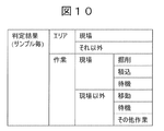
- FIG. 10 is a diagram showing a configuration example of areas and work determination results of the transporters 2-1 to 2-10 obtained by the work determination processing (see FIG. 9) of the transporters. It is a figure which shows the area of the conveyance machines 2-1 to 2-10, and the example of accumulation of the work determination result.
- FIG. 10 is a diagram showing a configuration example of areas and work determination results of the transporters 2-1 to 2-10 obtained by the work determination processing (see FIG. 9) of the transporters. It is a figure which shows the area of the conveyance machines 2-1 to 2-10, and the example of accumulation of the work determination result.
- FIG. 7 is a diagram showing an example of items of calculation processing results stored in a calculation/totalization result storage unit 606. It is an example of the extraction method of the conveyance machine with low work efficiency in the construction management system which concerns on this embodiment. It is a figure which shows the example of the method of transporter extraction with low work efficiency. It is a figure which shows the example of a movement route confirmation display which confirms the state of movement on a map. It is a flowchart for demonstrating the process which displays work management in the work terminal device 7 for the manager of the civil engineering construction site of this embodiment to confirm. It is a figure which shows the example which displays the conveyance machine in which the conveyance amount fell, and the work whose efficiency fell in the conveyance machine regarding a conveyance machine.
- embodiments of the present invention may be implemented by software operating on a general-purpose computer, dedicated hardware, or a combination of software and hardware, as described later.
- each piece of information of the present invention will be described in a “table” format, but these pieces of information do not necessarily have to be represented by a data structure of a table, and a data structure of a list, a DB, a queue, or the like and other than that. May be expressed as.
- FIG. 1 is a diagram showing an overall schematic configuration of a construction management system 10 according to the present embodiment.
- a construction management system 10 includes position information of a heavy machine 1 such as a hydraulic excavator at a civil engineering construction site (hereinafter, also simply referred to as “construction site” or “site”) and a transporter 2 such as a dump truck.
- Position information from -1 to 2-10 is a predetermined communication device (for example, a base station of a communication company) 4, and a server device 6 that collects and stores various data from the communication device 4 via the Internet 5 (network).
- a work terminal device 7 is provided for the manager of the civil construction site to confirm the processing result by the server device 6, for example.
- the portable terminal devices (or the heavy equipment 1 or the transport machines 2-1 to 2-10 installed in the heavy equipment 1 or the transport equipment (for example, dump truck) 2-1 to 2-10.
- GNSS Global Positioning Satellite System
- each mobile terminal device that receives the radio wave transmits the position information to the server device 6 via the base station of the communication company (may pass through the communication device 4), the line, or the Internet 5.
- the server device 6 performs various processes on the received data, and transmits necessary information to the work terminal device 7 for the manager of the civil construction site to confirm.
- the work terminal device 7 displays the processing result of the server device 6 on the screen in response to the instruction from the administrator.
- the heavy equipment 1 is a work machine capable of performing loading work on the transporters 2-1 to 2-10, and has a plurality of work functions such as excavation work other than loading work. It is a machine equipped.
- the mobile terminal device is a communication device such as a smartphone carried by a driver (operator) of the heavy machine 1 and the transport machines 2-1 to 2-10.
- the mobile terminal devices of the heavy equipment 1 and the transporters 2-1 to 2-10 may include not only a GPS sensor that measures position information but also other sensors that measure acceleration, angular velocity, geomagnetism, and the like.
- a terminal device for example, a built-in terminal device that can communicate with the communication device 4 or the server device 6 may be installed in the heavy equipment 1 or the transport machines 2-1 to 2-10.
- the work terminal device 7 for the administrator of the civil construction site to confirm is provided outside the civil construction site.
- the work terminal device 7 can bidirectionally communicate with the server device 6 via a communication line or a network. Therefore, the manager who operates the work terminal device 7 can access the server device 6 via the communication line, display the work status of the civil engineering construction site on the work terminal device 7, and confirm the contents.
- the work terminal device 7 is a general computer or a tablet that not only displays the work status of the civil engineering construction site but also can perform various calculations and work.
- the work terminal device 7 may be installed in a building installed inside a civil engineering construction site, or may be a mobile terminal device owned by an administrator.
- the portable terminal device possessed by the administrator also serves as the work terminal device 7, it is possible to grasp the work situation of the civil engineering construction site selected by the administrator even when the administrator is working in another place or the like. Will be possible.
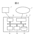
- FIG. 2 is a diagram showing an internal hardware configuration example of the server device 6 in the construction management system 10.
- the server device 6 has, for example, a calculation unit 6a, a first storage unit 6b, a second storage unit 6d, a network interface 6c, and an external network interface 6e as internal configurations.
- the work terminal device 7 is connected to the server device 6 via the external network interface 6e.
- the arithmetic unit 6a is composed of, for example, a central processing unit (CPU) that performs various arithmetic processes. That is, the arithmetic unit 6a functions as a control device that controls the server device 6 as a whole. For example, the arithmetic unit 6a performs arithmetic processing on various data input from the network interface 6c according to a program stored in the first storage unit 6b. The arithmetic unit 6a also controls the network interface 6c and also controls the communication of the server device 6 with respect to the communication line.
- CPU central processing unit
- the first storage unit 6b is a general main memory (main storage device) that temporarily stores programs and various data. Specifically, the first storage unit 6b temporarily stores the program executed by the calculation unit 6a, and further temporarily stores various data input to the server device 6 and calculation results by the calculation unit 6a. ..
- the first storage unit 6b is composed of a dynamic random access memory (DRAM: Dynamic Random Access Memory).
- DRAM Dynamic Random Access Memory
- the calculation result by the calculation unit 6a is, for example, a result of determining the positions of the heavy machine 1 and the transport machines 2-1 to 2-10, which will be described later, and a result regarding an area chart showing the position transitions of these in time series.
- the second storage unit 6d is a general storage (auxiliary storage device) that permanently stores various data. Specifically, the second storage unit 6d permanently stores the calculation result of the calculation unit 6a.
- the second storage unit 6d can be configured by a hard disk drive (HDD: hard disk drive) or a solid state drive (SSD: solid state drive).
- the external network interface 6e is connected to an ordinary computer (including a controller, a memory, an input device, an output device, etc.) or a work terminal device 7 composed of a tablet.
- the administrator of the server device 6 operates the input device of the work terminal device 7 (for example, a keyboard, a mouse, a touch panel, a mechanical switch, a pointing device, etc.) to use and maintain the server device 6.
- You can Further, the administrator can display the usage status, maintenance and inspection status, etc. on the display of the work terminal device 7 and browse the displayed output information.
- An output device such as a printer may be connected to the external network interface 6e.
- the calculation unit 6a of the server device 6 executes the display program for the work terminal device 7 at the work site, and the calculation result of the program via the communication line. Is transmitted to the work terminal device 7 and displayed on the display (display unit).
- the method of displaying the calculation result on the display (display unit) of the work terminal device 7 may be display by a method via a Web browser, or by execution of a program included in the work terminal device 7. May be Further, the work terminal device 7 may be, for example, a portable computer device such as a smartphone.
- FIG. 3 is a diagram showing a scene setting example to which the technique according to the present embodiment can be applied.
- the present embodiment is applied to, for example, work process management in a situation where a construction site, a work area, and a forward path/return path connecting them are used.
- the work area 110 indicates an excavation site (hereinafter referred to as a site), and the heavy equipment 1 excavates earth and sand, and the transport equipments 2-1 to 2-10 which are close to the heavy equipment 1 within a predetermined distance range. It is a place to load to.
- the work area 120 represents a soil dumping place, and is a place where the work machine discharges the soil loaded in the work area 110.
- the transporting machines 2-1 to 2-10 repeat the loading work in the work area 110 and the dumping work in the work area 120, and move between the work areas 110 and 120 a plurality of times. ..
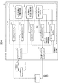
- FIG. 4 is a diagram showing functional blocks of the server device 6.
- the server device 6 easily grasps the work statuses of the heavy equipment 1 and the transporters 2-1 to 2-10 operating at the construction site 100 for the work of FIG. 3, and extracts elements having different performance tendencies. It has a function to improve work.
- the arithmetic unit 6a reads various processing programs from the first storage unit 6b, expands them on the internal memory of the arithmetic unit 6a, and executes the various processing programs. Then, the data of the processing result is stored in the second storage unit (storage) 6d.
- the manager of the civil engineering construction site via the work terminal device 7, area information, work information for each machine such as the heavy equipment 1 and the transport machines 2-1 to 2-10, and the transport machines 2-1 to 2- Orbit information for 10 is set.
- the area information represents a section in which latitude, longitude, etc. are designated on a map or in a tabular format.
- the work information indicates work that occurs in each area and other places in each machine type.
- the circulation information is defined by the administrator, for example. In the case of a transporter, for example, a series of operations for moving from the site to the dumping ground and returning to the site can be defined as one lap.
- the calculation unit 6a executes the setting processing program 601, and the generated data is stored in the area/work setting information storage unit 602 (storage 6d). Store.
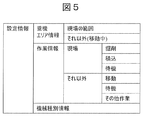
- FIG. 5 is a diagram showing a configuration example of heavy equipment setting information set for the heavy equipment 1.
- the heavy equipment setting information includes, for example, heavy equipment area information, work information, and machine type information.
- the heavy equipment area information is set, for example, as a work site such as excavation and loading, and other areas.
- the work information is information that identifies the type of work in each area, and for example, three types of excavation, loading, and standby are set for the site. In addition, in other areas, three types of work are set in addition to movement and waiting.
- specifications such as the model, bucket capacity, and rated output are set as the machine type information.
- a plurality of work types may be set for the area.
- FIG. 6 is a diagram showing a configuration example of transporter setting information set for the transporters 2-1 to 2-10.
- the carrier area information is set as, for example, the range of the site, the range of the dumping ground, and the others.
- the work information is information for identifying the type of work in each area, like the heavy equipment 1, and is for loading, waiting, and traveling at the site, and for dumping, waiting, and traveling at the dumping ground, other than that.
- the forward movement and the backward movement are set respectively.
- the outward movement means the movement from the site to the dumping ground
- the returning movement means the movement from the dumping ground to the ground.
- the machine type information is information including specifications such as model and maximum load capacity.
- the circulation information is setting information that defines one circulation of transportation by the transport machines 2-1 to 2-10. It is possible to set one lap from moving from the site to the dumping ground and returning to the site. According to the respective setting information, the calculation unit 6a determines the work area and work type of the heavy machine 1 and the transport machines 2-1 to 2-10. Hereinafter, each determination process will be described.
- the server device 6 receives the position information transmitted from the heavy equipment 1 or the transport machines 2-1 to 2-10 at the network interface 6c, and receives the received information from the second storage unit (storage unit). ) Store in 6d.
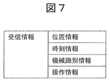
- the information received by the server device 6 includes position information, time information, machine identification information, operation information, and the like.
- the determination processing program 603 determines the area and the work (type) based on the received information and the information set by the administrator. In the case of the transport machines 2-1 to 2-10, the determination processing program 603 determines the circulation of the transport machines 2-1 to 2-10 according to the set circulation information (see FIG. 6).
- FIG. 8 is a flowchart (example) for explaining an example of heavy equipment work determination processing for determining the type of work performed by the heavy equipment 1.
- each step of FIG. 8 will be described by using the determination processing program 603 as the operation subject of the work determination processing, but as described above, the program is read and executed by the calculation unit 6a. Therefore, the determination processing program 603 may be replaced with the calculation unit (controller) 6a.
- Step 801 The determination processing program 603 determines from the position information of the heavy equipment 1 whether the heavy equipment 1 exists in the work area 110. If the heavy equipment 1 is present in the work area 110 (Yes in step 801), the process proceeds to step 802. If the heavy equipment 1 does not exist in the work area 110 (No in step 801), the process proceeds to step 807.
- Step 802 The determination processing program 603 determines whether the heavy equipment 1 is working. The determination as to whether or not work is being performed, for example, using information detected by a sensor installed in the heavy equipment 1 (for example, a sensor that detects the operation of the heavy equipment 1 or a sensor that detects actual movement such as hydraulic movement). May be performed, or an operation log or the like obtained separately may be used.
- a sensor installed in the heavy equipment 1 for example, a sensor that detects the operation of the heavy equipment 1 or a sensor that detects actual movement such as hydraulic movement. May be performed, or an operation log or the like obtained separately may be used.
- the process proceeds to step 803. If it is determined that the heavy equipment 1 is not working (No in step 802 ), the process proceeds to step 806.
- Step 803 The determination processing program 603 determines whether any of the transporters 2-1 to 2-10 is adjacent to the heavy equipment 1. Whether or not any of the transporters 2-1 to 2-10 is adjacent to the heavy equipment 1 is determined based on the position information of the heavy equipment 1 and the transporters 2-1 to 2-10, as well as beacon information that is separately obtained. It can be executed by using. When it is determined that the transport machines 2-1 to 2-10 are adjacent to the heavy equipment 1 (Yes in step 803), the process proceeds to step 804. When it is determined that the carrier machines 2-1 to 2-10 are not adjacent to the heavy equipment 1 (No in step 803), the process proceeds to step 805.
- Step 804 If any of the transporters 2-1 to 2-10 is adjacent to the heavy equipment 1, the determination processing program 603 determines that the heavy equipment 1 is carrying out the loading work at the site, and Set the area and work determination result to "loading on site".
- Step 805 When none of the transporters 2-1 to 2-10 is adjacent to the heavy equipment 1, the determination processing program 603 determines that the heavy equipment 1 is performing the excavation work on site, and the area of the heavy equipment 1 and The work judgment result is set to "site drilling".
- Step 806 When the heavy equipment 1 is not working, the determination processing program 603 determines that the heavy equipment 1 is in the standby state at the site, and sets the area of the heavy equipment 1 and the work determination result to “site standby”.
- Step 807 Similar to step 802, the determination processing program 603 determines whether or not the heavy equipment 1 is working even when the heavy equipment 1 exists outside the work area 110. If it is determined that the heavy equipment 1 is working (Yes in step 807), the process proceeds to step 809. When it is determined that the heavy equipment 1 is not working (No in step 807), the process proceeds to step 808.
- Step 808 When the heavy equipment 1 is not working, the determination processing program 603 determines whether or not the heavy equipment 1 is moving. The determination as to whether or not the heavy equipment 1 is moving can be made, for example, by calculating the speed from the temporal change in the position information of the heavy equipment 1, but another method may be used. If it is determined that the heavy equipment 1 is moving (Yes in step 808), the process proceeds to step 810. If it is determined that the heavy equipment 1 is not moving (No in step 808 ), the process proceeds to step 811.
- Step 809 When the heavy equipment 1 is working, the determination processing program 603 determines that the heavy equipment 1 is performing work outside the site, and sets the area of the heavy equipment 1 and the work determination result to “work other than on-site”.
- Step 811 When the heavy equipment 1 is not moving, the determination processing program 603 determines that the heavy equipment 1 is on standby except at the site. Set the area and work determination result to "standby outside the site".
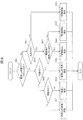
- FIG. 9 is a flowchart for explaining an example of a transporter work determination process for determining the type of work performed by the transporters 2-1 to 2-10.
- the determination processing program 603 as the operation subject of the work determination processing, but as described above, the program is read and executed by the calculation unit 6a. Therefore, the determination processing program 603 may be replaced with the calculation unit (controller) 6a.
- Step 901 The determination processing program 603 determines whether or not the transporters 2-1 to 2-10 are present in the work area 110 based on the position information of the transporters 2-1 to 2-10. When it is determined that the carriers 2-1 to 2-10 are present in the work area 110 (Yes in step 901), the process proceeds to step 902. When it is determined that the carrier machines 2-1 to 2-10 do not exist in the work area 110 (No in step 901), the process proceeds to step 908.
- Step 902 The determination processing program 603 determines whether or not the transporting machines 2-1 to 2-10 (transportation machine to be determined) are traveling. Whether or not the transport machines 2-1 to 2-10 are traveling can be determined, for example, by calculating the speed from the temporal change of the position information of the transport machines 2-1 to 2-10. Another method may be used. If it is determined that the transport machines 2-1 to 2-10 are traveling (Yes in step 902), the process proceeds to step 907. When it is determined that the transport machines 2-1 to 2-10 are not traveling (No in step 902), the process proceeds to step 903.
- Step 903 The determination processing program 603 determines whether or not there is a preceding transporter for the determination target transporter.
- the determination in step 903 is made, for example, sequentially (one by one) for each of the transporters 2-1 to 2-10 and whether another transporter is present in the work area 110 in advance. That is, the presence/absence of the preceding transporter is determined based on, for example, the presence/absence of another transporter in the work area 110 before the target transporter and staying there. If there is a preceding carrier (Yes in step 903), the process proceeds to step 906. If there is no preceding carrier (No in step 903), the process proceeds to step 904.
- Step 904 The determination processing program 603 determines whether or not the heavy equipment 1 is in the process of loading adjacent to the transporting machine to be determined. Whether or not the heavy machine is adjacent to the transport machine to be determined is similar to the processing of step 803, for example, in addition to the position information of the heavy machine 1 and the transport machines 2-1 to 2-10, the information of the separately acquired beacon. It can be executed by using. In addition, whether or not the determination target transporter is under loading operation is determined by, for example, a sensor installed in the heavy equipment 1 adjacent to the determination target transporter (for example, the operation of the heavy equipment 1 as in the process of step 802).
- step 904 If the adjacent heavy equipment 1 is under loading operation (Yes in step 904), the process proceeds to step 905. If the heavy equipment 1 is not in the loading operation (No in step 904 ), the process proceeds to step 906.
- Step 905 When the loading operation is being performed by the adjacent heavy equipment 1, the determination processing program 603 determines that the transportation machines 2-1 to 2-10 (transportation apparatuses to be determined) are in the loading operation at the site, and makes a determination. Set the area of the target transporter and the work determination result to "Site loading".
- Step 906 When the loading operation is not performed by the heavy equipment 1, the determination processing program 603 determines that the transport machines 2-1 to 2-10 (transportation machines to be determined) are on standby at the site, and the determination target Set the area of the transporter and the work judgment result to "Standby".
- Step 907 When the transport machines 2-1 to 2-10 (transportation vehicles to be determined) are running, the transport processing machines 2-1 to 2-10 (transportation vehicles to be determined) are running in the field. It is determined that there is, and the area of the transport machine to be determined and the work determination result are set to “on-site driving”.
- Step 908 When it is determined that the transport machines 2-1 to 2-10 do not exist in the work area 110, the determination processing program 603 uses the position information of each of the transport machines 2-1 to 2-10 to determine the transport machine 2-1. From 2 to 10, it is determined whether or not 2-10 (transportation machine to be determined) is in the work area 120. If it is determined that the transporters 2-1 to 2-10 (transportation device to be determined) are in the work area 120 (Yes in step 908), the process proceeds to step 909. When it is determined that the transport machines 2-1 to 2-10 (transportation machine to be determined) are not in the work area 120 (No in step 908), the process proceeds to step 915.
- Step 909 When the transport machines 2-1 to 2-10 are in the work area 120, the determination processing program 603 is running the transport machines 2-1 to 2-10 (transport vehicle to be determined) as in step 902. Or not. When it is determined that the transport machines 2-1 to 2-10 are traveling (Yes in step 909), the process proceeds to step 912. When it is determined that the transport machines 2-1 to 2-10 are not traveling (No in step 909), the process proceeds to step 910.
- Step 910 When the transport machines 2-1 to 2-10 are not traveling, the determination processing program 603 determines whether or not there is a transport machine preceding the transport machine to be determined, as in step 903. If there is a preceding carrier (Yes in step 910), the process proceeds to step 911. If there is no preceding carrier (No in step 910), the process proceeds to step 914.
- Step 911 The determination processing program 603 determines whether or not the determination target transporters 2-1 to 2-10 are in the earth discharging operation when there is a transporter preceding the determination target transporter. Whether or not the transporting machines 2-1 to 2-10 to be judged are in the process of discharging soil is determined by, for example, whether or not the raising/lowering operation of the loading platform (the loading platform for loading the sand) of the transporting system is detected (the transporting system concerned). It can be determined by a sensor provided in. When it is determined that the target transporting machines 2-1 to 2-10 are not performing the soil dumping work (No in step 911), the process proceeds to step 913. When it is determined that the determination target transporters 2-1 to 2-10 are performing the dumping work (Yes in step 911), the process proceeds to step 914.
- Step 912 When the transport machines 2-1 to 2-10 are running, the determination processing program 603 determines that the transport machines 2-1 to 2-10 (transport machines to be determined) are running on the dumping ground. , Set the area of the transporting machine to be determined and the work determination result to "Traveling at the disposal site (earth dumping site)".
- Step 913 The determination processing program 603 determines that the transporters 2-1 to 2-10 are not waiting for dumping work, and the transporters 2-1 to 2-10 (transportation device to be determined) are on standby at the dumping ground. Then, the area of the transporting machine to be judged and the work judgment result are set to "standby for the processing site (earth dump)".
- Step 914 When the transport machines 2-1 to 2-10 are in the work of dumping, the transport processing machines 2-1 to 2-10 (transport vehicle to be determined) are in the dumping process at the dumping ground. It is determined that there is, and the area of the transporting machine to be determined and the work determination result are set in the “processing site (earth dump) dumping”.
- Step 915 When the transport machines 2-1 to 2-10 are not in the work area 120, the determination processing program 603 determines that the transport machines 2 to 2-10 are based on the position information of the transport machines 2-1 to 2-10 (the transport machines to be determined). It is determined whether -1 to 2-10 (transportation machine to be determined) has not arrived at the dumping ground in the area 120. Whether or not it is before arriving at the dumping ground is determined based on a change in the position information of the transporting machine 201 to 2-10 (transportation machine to be determined) (whether it is approaching the dumping ground or moving away from it). It can be carried out. If it is determined that it has not arrived at the dumping ground (Yes in step 915 ), the process proceeds to step 916. When it is determined that it has not arrived at the dumping ground (the work area 120 has been left) (No in step 915), the process proceeds to step 917.
- Step 916 When the transport machines 2-1 to 2-10 have not arrived at the dumping ground before the transport machines 2-1 to 2-10 (transportation machine to be determined) arrive at the dumping ground, the determination processing program 603 It is determined that there is (approaching the dumping ground), and the area of the transporting machine to be determined and the work determination result are set to “moving (outward)”.
- Step 917 If the transport machines 2-1 to 2-10 have not arrived at the dumping ground before the transport machines 2-1 to 2-10 (the transport machine to be determined) arrive at the dumping ground, the determination processing program 603 It is determined that there is no (distance from the dumping ground), and the area of the transport machine to be determined and the work determination result are set to "move (return)".
- FIG. 10 is a diagram showing a configuration example of the area of the heavy equipment 1 and the work determination result obtained by the work determination processing (see FIG. 8) of the heavy equipment 1.
- the items included in the area of the heavy equipment 1 and the result of the work are obtained according to the information (items) set in the heavy equipment setting information (see FIG. 5).
- the area of the heavy equipment 1 and the work determination result are composed of information of a pair of the determined area and the determined work.
- the work determination process (see FIG. 8) of the heavy equipment 1 is executed, for example, at predetermined time intervals (for example, every 10 seconds), so that the determination result is created every time the work determination process is executed. In some cases, it may be determined that the heavy machine 1 is in the process of loading at a certain site at a certain determination timing, and that it is on standby at a place other than the site at another determination timing.
- FIG. 11 is a diagram showing a configuration example of areas and work determination results of the transporters 2-1 to 2-10 obtained by the work determination processing (see FIG. 9) of the transporters.
- the items included in the areas of the transporters 2-1 to 2-10 and the result of the work are obtained according to the information (items) set in the transporter setting information (see FIG. 6).
- the “round” in the determination result of FIG. 11 is counted according to the round information set in FIG.
- the area and work determination results of the transport machines 2-1 to 2-10 are composed of information on the pair of the determined area and the determined work.
- the work determination process of the transport machines 2-1 to 2-10 (see FIG. 9) is executed, for example, at predetermined time intervals (for example, every 10 seconds). Therefore, the determination result is returned each time the work determination process is executed. Will be created. In some cases, it may be determined that the transporting machine 2-1 is in the process of loading at the site at a certain determination timing, and that it is traveling in the dumping field at another determination timing. .. Further, such a determination result is stored for each of the transporters 2-1 to 2-10.
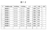
- FIG. 12 is a diagram showing an example of accumulation of areas and work determination results of the transport machines 2-1 to 2-10.
- the area and work determination results for the transporters 2-1 to 2-10 are received by the network interface 6c and stored in the received information/determination result storage unit 604.
- the area and work determination results are the area information and work information obtained by the determination process for the respective data (machine identification information, time information, position information) of the transport machines 2-1 to 2-10. And the lap information are added.
- only the transport machine 2-1 is described, but such information is accumulated for all the transport machines 2-1 to 2-10.
- the calculation/aggregation processing program 605 calculates the transport amount, the time per lap, and the like for each transport machine, work, and time zone, and the second storage unit (storage) 6d. It is stored in the calculation/totalization result storage unit 606.
- FIG. 13 is a diagram showing an example of items of calculation processing results stored in the calculation/totalization result storage unit 606.
- the calculation/aggregation result storage unit 606 stores the result of calculation of the transport amount/number of times by the transport machines 2-1 to 2-10 and time zones, the time per lap, and the time per work by the calculation/aggregation processing program 605. It In the present embodiment, as the transportation amount, the product of the loading amount and the number of laps is calculated for each transportation device, and the calculated value is added up for all the transportation devices.
- the extraction processing program 607 uses the calculation/totalization result stored in the calculation/totalization result storage unit 606 to extract a transporter, a time zone, a work, etc. having a lower work efficiency than other transporters.
- FIG. 14 is a diagram showing an example of a method for extracting a transporter with low work efficiency.
- FIG. 14 shows a histogram with respect to the number of transportation times of the transport machines 2-1 to 2-10.
- FIG. 14 an example is shown in which a transporter 2-3 having a single transport count that has a standard deviation twice (2 ⁇ ) or more smaller than the average value is extracted from the average value. Further, in the present embodiment, the deviation from the average value assuming the normal distribution is used for extracting the transporter with low work efficiency, but outliers can be applied by applying clustering or One Class SVM to the number of transports. It is also possible to use other anomaly extraction techniques, such as extracting
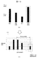
- FIG. 15 is a diagram showing an example of abnormality degree determination processing by the abnormality degree determination/extraction processing program 608.
- the abnormality degree determination/extraction processing program 608 executes processing for extracting a work type having particularly low work efficiency in the transport machine, time zone, work, etc. having low work efficiency extracted by the extraction processing program 607.
- a histogram of required time is created for each work type of all transporters (loading work, outward/return trip movement, earth discharging work, etc.), and the extraction processing program 607 is used.
- the return travel time which is a work with a large deviation from the average, is determined to be abnormal.
- a region 1501 shows a histogram of all transport machines created for loading work, forward movement, soil discharging work, and return movement.
- the abnormality degree determination/extraction processing program 608 determines the deviation from the average value of the transport machine extracted by the extraction processing program 607 based on this information (in FIG. 15B, an example of the return travel time is displayed). ..
- the deviation from the average is used as the abnormality degree, and as a result, it is determined that the return path has the highest abnormality degree and there is room for improvement.
- the histogram and the deviation from the average value are used for the abnormality determination assuming the normal distribution. However, for example, clustering or OneClass SVM is applied to the return time, and the outlier value is applied. It is also possible to use other abnormality extraction techniques, such as extracting
- FIG. 16 is a diagram showing a movement route confirmation display example for confirming the movement state on the map.
- a screen for confirming the return route on the map where the degree of abnormality of the transporter 2-3 is high is shown.
- each carrier 2-1 to 2-10 can be displayed on the map using the position data.
- the carrier 2-3 follows a route 1602 different from the route 1601 used by the other carriers 2-1, 2-2 and 2-4 to 2-10.
- a transporter with low work efficiency and its work type are specified as extraction of work efficiency reduction, but the present invention is not limited to this.
- FIG. 17 is a flow chart for explaining a process of displaying work management on the work terminal device 7 for the manager of the civil construction site of the present embodiment to confirm.
- each step of FIG. 8 will be described by using various processing programs as the operation subject of the work management process, but as described above, the programs are read and executed by the calculation unit 6a. Therefore, the various processing programs may be replaced with the calculation unit (controller) 6a.
- Step 1701 The network interface 6c acquires the position information of each from the communication device (communication company base station) 4 or the transporters 2-1 to 2-10. Then, the network interface 6c stores the acquired information in the reception information/judgment result storage unit 604 and transfers it to the judgment processing program 603.
- Step 1702 The judgment processing program 603 judges the area (for example, the site, the dumping ground, or the moving place) and the work type (for example, loading, waiting, traveling) of the transport machines 2-1 to 2-10 at the relevant time. Then, the determination result is displayed on the screen of the work terminal device 7. Then, the determination processing program 603 stores the determination result in the reception information/determination result storage unit 604.
- Step 1703 The calculation/aggregation processing program 605 reads the determination result of the area and work type of each of the transporters 2-1 to 2-10 from the reception information/determination result storage unit 604, and transports the transportation amount and the required time per round. Calculate (perform statistical processing) for each work and time zone of each of the machines 2-1 to 2-10. Then, the calculation/totalization processing program 605 stores the calculation result in the calculation/totalization result storage unit 606 and transfers it to the extraction processing program 607.
- Step 1704 The extraction processing program 607 reads out the calculation/totalization result from the calculation/totalization result storage unit 606, determines whether or not there is a transporter with low work efficiency for each transporter as compared with other transporters. Extract the information of the carrier. Then, the extraction processing program 607 stores the judgment and extraction results in the calculation/aggregation result storage unit 606 and transfers them to the abnormality degree judgment/extraction processing program 608, and transfers the low work efficiency transporter via the external network interface 6e. Is transmitted to the work terminal device 7. If there is a transporter whose work efficiency has decreased (Yes in step 1704), the process proceeds to step 1705. If there is no transporting machine whose work efficiency has decreased (No in step 1704), the process proceeds to step 1709. In addition, when a normal distribution is assumed from the data and a deviation from the average value is set, in the determination of step 1704, the state of “no low work efficiency transporter: No” may not appear.
- Step 1705 The abnormality degree determination/extraction processing program 608 determines whether or not there is a work type of which the efficiency is low with respect to the transporter whose work efficiency is reduced, and when there is, extracts information of the low efficiency work type. Specifically, the abnormality degree determination/extraction processing program 608 sets the required time for each work type of the transporting machine as shown in FIG. 15 (for example, loading work, outward/return trip movement, and earth discharging work). A histogram is created to determine whether there is an inefficient work type. If there is a work with low efficiency (Yes in step 1705), the process proceeds to step 1706.
- step 1705 If there is no work with low efficiency (for example, if the efficiency of all works is lower than that of other transporters: No in step 1705 ), the process proceeds to step 1708.
- the state of “no low-efficiency work type: No” may not appear in the determination in step 1705.
- Step 1706 The abnormality degree determination/extraction processing program 608 stores the determination result in the calculation/totalization result storage unit 606, extracts the low-efficiency work type via the external network interface 6e, and outputs the information to the work terminal device 7. Send.
- Step 1707 The work terminal device 7 (a controller (not shown) of the work terminal device) displays the information of the transporter with low work efficiency and the information of the work type with low efficiency of the transporter on the display screen of the work terminal device 7.
- Step 1708 The work terminal device 7 (a controller (not shown) of the work terminal device) displays the information of the transporter having low work efficiency on the display screen of the work terminal device 7.
- the work terminal device 7 displays the progress status of the work on the display screen of the work terminal device 7 (performs work progress display).
- the progress of the work is calculated, for example, by a manager or the like before the construction (initial stage of the construction) to measure the density of the soil at the construction site and calculate the mass (weight) per unit volume. Then, by summing the weight per unit volume, the transport capacity specifications of the transporters 2-1 to 2-10, and the number of transports of each transporter, the total transport amount (actual) can be calculated.
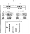
- FIG. 18 is a diagram showing an example of displaying, with respect to the transporters 2-1 to 2-10, a transporter with a reduced transport amount and a work with reduced efficiency in the transporter.
- the progress 1802 for the target total amount of transportation 1801 is shown as the progress of the transporters 2-1 to 2-10. Furthermore, the transport amount of each of the transporters 2-1 to 2-10 is shown. And the number of transportations and the time transition are displayed. Among them, the transporter 2-5 having low work efficiency extracted by the extraction processing program 607 is highlighted like a bar 1803. For example, when the manager of the civil engineering construction site selects the transporter 2-5 of the bar 1803, the degree of abnormality of each work of the bar 1803 is displayed as a histogram 1804. In the histogram 1804, the work with the highest degree of abnormality (returning movement in this embodiment) is displayed as a bar 1805.
- the abnormalities are ranked by, for example, the degree of deviation from the average value, and the work with the highest abnormalities, in the present embodiment, the return path is moved. It is displayed most emphasized.
- the operation unit 6a of the server device 6 automatically analyzes the elements such as the work and the transport machine having low work efficiency, and the analysis result concerned manages the construction site. Will be provided to the person. As a result, the manager of the construction site can more easily understand the work situation at the construction site and can improve the work efficiency of the entire construction site from the work content.
- the server device 6 acquires the position information of at least one transporter, and determines whether the transporter is performing a predetermined work or is moving based on the position information.
- a process for generating work type information for example, excavation, loading, waiting, movement, and other (separate) work
- a process for calculating the required time for each work type information of the transporter for example, excavation, loading, waiting, movement, and other (separate) work
- the first rule relating to the required time is compared with each other information (for example, "select the work that took the longest required time” or select the work that deviates from the average required time of all types of work by a predetermined time or more).
- the plurality of transport machines 2-1 to 2-10 and the working machine are managed by the construction management system.
- the server device 6 acquires the position information of each of the plurality of transport machines 2-1 to 2-10 and the position information of at least one work machine, and the position of the plurality of transport machines and work machines.
- a process of generating work type information for each predetermined time of the plurality of transport machines 2-1 to 2-10 and the work machine, and a second rule regarding the work amount for example, “work amount is the most A carrier with a low workload among multiple carriers based on "Select a small carrier” or "Select a carrier with a work volume of - ⁇ or -2 ⁇ ( ⁇ is a standard deviation) or less.
- the required time is compared for each work type information, and the first rule (for example, “selecting the work that took the longest time is Select a work that deviates from the average value of the required time for each type of work by more than a predetermined time.)), the process of extracting work elements with low work efficiency, information on the transporter with low work volume, and work efficiency And a process of outputting a low work element and.
- the first rule for example, “selecting the work that took the longest time is Select a work that deviates from the average value of the required time for each type of work by more than a predetermined time.
- the traveling/moving of the transporter (for example, moving from the site (site 1) to the treatment plant (soil dumping site: site 2)) or the transport of the transporter on site or within the treatment plant (site) is performed by each transport. It is detected by the temporal change of the aircraft position information. The moving speed of the carrier can also be calculated from the temporal change of the position information.
- the location of the transporter at the time when the work type information is generated (for example, whether it is at the site, at the processing site (earth dump), or when connecting the site and the soil dump) You can determine whether you are on a road (eg, road).
- the transport machine determines whether or not the transport machine is adjacent to the work machine at the timing of generating the work type information (whether the position of the transport machine and the position of the work machine are adjacent to each other). Good. When the transport machine is adjacent to the work machine, it may be determined that the transport machine and the work machine cooperate to perform the first work. In addition, at the timing of generating the work type information based on the motion detection information by the sensor (for example, a sensor (hydraulic pressure sensor, etc.) that detects the operation of the carrier of the transport machine), the transport machine determines whether the second operation is performed. It may be determined that a work (for example, a discharge work on a dumping ground) is being performed.
- the sensor for example, a sensor (hydraulic pressure sensor, etc.) that detects the operation of the carrier of the transport machine
- the position information of the judgment target transporter among the plurality of transporters and the temporal change of the position information there is another transporter preceding the judgment target transporter in the predetermined area.
- it may be determined whether or not the target transporter is waiting in a predetermined area for example, when it is not detected that the target transporter has entered the site or treatment site and performed work, If you have stopped for a certain period of time without traveling, determine that you are on standby).
- a work course in which a transporter patrols a site (earth dumping site) other than a site where a first work (for example, loading) and a second work (for example, earth dumping) are performed can be constituted by a plurality of places including the road and a road connecting the plurality of places.
- set a circling rule in advance in the work course (for example, it is possible to make one lap from entry into work, exit ⁇ outbound ⁇ dumping site admission to work ⁇ exit ⁇ return ⁇ arrival at site) May be.
- the server device 6 calculates the number of laps of the work course by the transporter based on the position information of the transporter and the lap rule, and uses the information of the number of laps as the information of the number of transports by the transporter with low work efficiency. You may make it output with a work element.
- the functions of this embodiment can also be realized by program code of software.
- a storage medium storing the program code is provided to the system or device, and the computer (or CPU or MPU) of the system or device reads the program code stored in the storage medium.
- the program code itself read from the storage medium realizes the functions of the above-described embodiments, and the program code itself and the storage medium storing the program code constitute the present invention.
- a storage medium for supplying such a program code for example, a flexible disk, a CD-ROM, a DVD-ROM, a hard disk, an optical disk, a magneto-optical disk, a CD-R, a magnetic tape, a non-volatile memory card, a ROM. Etc. are used.
- the OS operating system
- the CPU of the computer performs a part or all of the actual processing based on the instruction of the program code, and the processing.
- the functions of the above-described embodiments may be realized by.
- the program code is stored in a storage means such as a hard disk or a memory of a system or an apparatus or a storage medium such as a CD-RW or a CD-R.
- a storage means such as a hard disk or a memory of a system or an apparatus or a storage medium such as a CD-RW or a CD-R.
- the computer (or CPU or MPU) of the system or apparatus may read out and execute the program code stored in the storage means or the storage medium at the time of use.
- control lines and information lines are shown to be necessary for explanation, and not all control lines and information lines are shown on the product. All configurations may be connected to each other.
Landscapes
- Business, Economics & Management (AREA)
- Engineering & Computer Science (AREA)
- Human Resources & Organizations (AREA)
- Economics (AREA)
- Strategic Management (AREA)
- Entrepreneurship & Innovation (AREA)
- Physics & Mathematics (AREA)
- General Physics & Mathematics (AREA)
- Development Economics (AREA)
- Educational Administration (AREA)
- General Business, Economics & Management (AREA)
- Tourism & Hospitality (AREA)
- Marketing (AREA)
- Theoretical Computer Science (AREA)
- Quality & Reliability (AREA)
- Operations Research (AREA)
- Game Theory and Decision Science (AREA)
- General Engineering & Computer Science (AREA)
- Civil Engineering (AREA)
- Mining & Mineral Resources (AREA)
- Structural Engineering (AREA)
- Health & Medical Sciences (AREA)
- General Health & Medical Sciences (AREA)
- Primary Health Care (AREA)
- Management, Administration, Business Operations System, And Electronic Commerce (AREA)
- Operation Control Of Excavators (AREA)
- Component Parts Of Construction Machinery (AREA)
- Time Recorders, Dirve Recorders, Access Control (AREA)
Abstract
施工現場において稼働する複数の作業機械及び運搬機の作業状況を容易に把握できるとともに、目標値に拘わらずに相対的に作業効率が低い作業や運搬機械などの要素を特定し作業効率の改善を図ることができる施工管理システムを提供する。本発明は、少なくとも1つの運搬機の作業状況を管理する作業管理情報を生成し、出力するサーバ装置であって、作業管理情報を生成するためのプログラムを格納する記憶デバイスと、記憶デバイスからプログラムを読み込み、実行して作業管理情報を生成するコントローラと、を備え、コントローラは、少なくとも1つの運搬機の位置情報を取得する処理と、位置情報に基づいて運搬機が所定の作業を行っているか、あるいは移動中であるかを示す作業種別情報を生成する処理と、運搬機の作業種別情報毎の所要時間を算出する処理と、所要時間を作業種別情報毎に比較し、所要時間に関する第1のルールに基づいて作業効率の低い作業要素を抽出する処理と、抽出された作業効率の低い作業要素を出力する処理と、を実行する、サーバ装置を提供する(図18参照)。
Description
本発明は、運搬機や作業機械等の作業状況を管理する施工管理システムに関する。
ダンプ等の運搬機及び当該運搬機に対して積込作業を行う油圧ショベル等の作業機械によって作業を進める土木施工現場において、当該施工現場の管理者(監督者)が施工現場の作業状況等を把握することが重要となっている。そして、当該管理者には、作業状況に応じて作業計画の変更や、作業効率の改善等が求められることになる。
従来から行われている作業機械効率向上の方法として、作業機械の各パラメータの目標値を設定して、目標値との差分を示し効率を改善する方法がある。例えば、特許文献1は、油圧やエンジン回転数に対して目標値を設定し、目標値と乖離している場合に予め用意していたメッセージを表示することを開示している。
しかしながら、特許文献1に開示の技術では、あくまでも目標値を設定し、設定された機械運転状態の目標値と実際の頻度分布とを比較し、差分に応じて予め用意してあるメッセージを出力するのみである。このため、油圧ショベル等の作業機械の動作を検知して個々の作業効率が目標値に近づくものの、目標に達している状態ではそれ以上の改善は見込めない。また、土木作業現場における運搬機はレンタルなどにより日々異なることも考えられるため、全ての機械に目標値を設定することは困難であったり、可能であったとしても非常に煩雑であったりする。さらに、土木作業現場全体の作業管理においては、積込作業を行う作業機械単体のみならず、土木施工現場で生じる掘削土を運搬する運搬機の作業をはじめ複数の機械の状態を把握し、効率を改善させることが求められている。
本発明はこのような状況に鑑みてなされたものであり、目標値とは関係なく相対的に効率が低い作業や運搬機械などの要素を特定して作業効率の改善を図る技術を提供する。
上記課題を解決するため、本発明は、少なくとも1つの運搬機の作業状況を管理する作業管理情報を生成し、出力するサーバ装置であって、作業管理情報を生成するためのプログラムを格納する記憶デバイスと、記憶デバイスからプログラムを読み込み、実行して作業管理情報を生成するコントローラと、を備え、コントローラは、少なくとも1つの運搬機の位置情報を取得する処理と、位置情報に基づいて運搬機が所定の作業を行っているか、あるいは移動中であるかを示す作業種別情報を生成する処理と、運搬機の作業種別情報毎の所要時間を算出する処理と、所要時間を作業種別情報毎に比較し、所要時間に関する第1のルールに基づいて作業効率の低い作業要素を抽出する処理と、抽出された作業効率の低い作業要素を出力する処理と、を実行する、サーバ装置を提供する。
本発明に関連する更なる特徴は、本明細書の記述、添付図面から明らかになるものである。また、本発明の態様は、要素及び多様な要素の組み合わせ及び以降の詳細な記述と添付される請求の範囲の様態により達成され実現される。
本明細書の記述は典型的な例示に過ぎず、請求の範囲又は適用例を如何なる意味に於いても限定するものではないことを理解する必要がある。
本明細書の記述は典型的な例示に過ぎず、請求の範囲又は適用例を如何なる意味に於いても限定するものではないことを理解する必要がある。
本発明によれば、施工現場において稼働する作業機械及び運搬機の作業状況を容易に把握できるとともに、作業効率の傾向が異なる要素を抽出し、当該作業の改善を図ることができる。
本実施形態は、施工現場において稼働する複数の作業機械及び運搬機の作業状況を容易に把握できるとともに、目標値に拘わらずに相対的に作業効率が低い作業や運搬機械などの要素を特定し作業効率の改善を図ることができる施工管理システムについて開示する。
以下、添付図面を参照して本発明の実施形態について説明する。添付図面では、機能的に同じ要素は同じ番号で表示される場合もある。なお、添付図面は本発明の原理に則った具体的な実施形態と実装例を示しているが、これらは本開示の理解のためのものであり、決して本発明を限定的に解釈するために用いられるものではない。その要旨を変更しない範囲において任意に変更して実施することが可能である。また、本実施形態で用いる様々な数値などは、いずれも一例を示すものであり、必要に応じて様々に変更することが可能である。
本実施形態では、当業者が本発明を実施するのに十分詳細にその説明がなされているが、他の実装・形態も可能で、本発明の技術的思想の範囲と精神を逸脱することなく構成・構造の変更や多様な要素の置き換えが可能であることを理解する必要がある。
更に、本発明の実施形態は、後述されるように、汎用コンピュータ上で稼動するソフトウェアで実装しても良いし専用ハードウェア又はソフトウェアとハードウェアの組み合わせで実装しても良い。
なお、以後の説明では「テーブル」形式によって本発明の各情報について説明するが、これら情報は必ずしもテーブルによるデータ構造で表現されていなくても良く、リスト、DB、キュー等のデータ構造やそれ以外で表現されていても良い。
以下では「プログラム」を主語(動作主体)として本発明の実施形態における各処理について説明を行うが、プログラムはコントローラによって実行されることで定められた処理をメモリ及び通信ポート(通信制御装置)を用いながら行うため、コントローラを主語とした説明としてもよい。
<施工管理システムの全体構成>
図1は、本実施形態に係る施工管理システム10の全体概略構成を示す図である。
図1に示すように、施工管理システム10は、土木施工現場(以下、単に「施工現場」や「現場」とも称する)における油圧ショベル等の重機1の位置情報、及びダンプトラック等の運搬機2-1から2-10の位置情報を所定の通信装置(例えば、通信会社の基地局)4と、通信装置4からインターネット5(ネットワーク)を介して各種データを収集して蓄積するサーバ装置6と、土木施工現場の管理者が例えばサーバ装置6による処理結果を確認するための作業端末装置7と、を備えている。
図1は、本実施形態に係る施工管理システム10の全体概略構成を示す図である。
図1に示すように、施工管理システム10は、土木施工現場(以下、単に「施工現場」や「現場」とも称する)における油圧ショベル等の重機1の位置情報、及びダンプトラック等の運搬機2-1から2-10の位置情報を所定の通信装置(例えば、通信会社の基地局)4と、通信装置4からインターネット5(ネットワーク)を介して各種データを収集して蓄積するサーバ装置6と、土木施工現場の管理者が例えばサーバ装置6による処理結果を確認するための作業端末装置7と、を備えている。
具体的に、施工管理システム10において、重機1や運搬機(例えば、ダンプトラックなど)2-1から2-10に設置された携帯端末装置(あるいは重機1や運搬機2-1から2-10に設置された固定端末でもよい)は、全球測位衛星システム(GNSS:Global Navigation Satellite System)を構成する複数の測位衛星3からの電波(位置情報)を受信する。その後、当該電波受信した各携帯端末装置は、位置情報を通信会社の基地局(通信装置4を経由してもよい)、回線やインターネット5を介してサーバ装置6に送信する。サーバ装置6は、受信したデータに対して各種処理を施し、土木施工現場の管理者が確認するための作業端末装置7へ必要な情報を送信する。作業端末装置7は、管理者の指示に応答して、サーバ装置6による処理結果を画面に表示する。
ここで、重機1とは、運搬機2-1から2-10に対して積込作業を行うことができる作業機械であり、積込作業以外にも掘削作業をはじめとした複数の作業機能を備える機械である。また、携帯端末装置は、重機1および運搬機2-1から2-10の運転者(操縦者)が所持するスマートフォンなどの通信機器である。なお、重機1および運搬機2-1から2-10の携帯端末装置は、位置情報を測定するGPSセンサだけでなく、加速度や角速度、地磁気などを測定する他のセンサを有してもよい。また、携帯端末装置の代わりに、重機1や運搬機2-1から2-10に通信装置4やサーバ装置6と通信可能な端末装置(例えば、備え付けの端末装置)を設置してもよい。
図1に示すように、本実施形態に係る施工管理システム10において、土木施工現場の管理者が確認するための作業端末装置7は、土木施工現場の外部に設けられている。そして、作業端末装置7は、通信回線あるいはネットワークを介してサーバ装置6と双方向に通信可能となっている。このため、作業端末装置7を操作する当該管理者は、通信回線を介してサーバ装置6にアクセスし、土木施工現場の作業状態を作業端末装置7に表示させ、その内容を確認することができる。ここで、作業端末装置7は、土木施工現場の作業状態を単に表示させるだけでなく、各種の演算及び作業等を行える一般的なコンピュータ、またはタブレットである。
なお、作業端末装置7は、土木施工現場の内部に設置された建屋内に設置されてもよく、又は管理者が所持する携帯端末装置であってもよい。特に、管理者が所持する携帯端末装置が作業端末装置7を兼ねることにより、管理者が他の場所等で作業している場合でも、管理者が選択する土木施工現場の作業状況を把握することが可能になる。
<サーバ装置6の内部ハードウェア構成>
図2は、施工管理システム10におけるサーバ装置6の内部ハードウェア構成例を示す図である。
図2に示されるように、サーバ装置6は、内部構成として、例えば、演算部6aと、第1記憶部6bと、第2記憶部6dと、ネットワーク・インターフェイス6cと、外部ネットワーク・インターフェイス6eと、を備え、外部ネットワーク・インターフェイス6eを介して作業端末装置7がサーバ装置6と接続されている。
図2は、施工管理システム10におけるサーバ装置6の内部ハードウェア構成例を示す図である。
図2に示されるように、サーバ装置6は、内部構成として、例えば、演算部6aと、第1記憶部6bと、第2記憶部6dと、ネットワーク・インターフェイス6cと、外部ネットワーク・インターフェイス6eと、を備え、外部ネットワーク・インターフェイス6eを介して作業端末装置7がサーバ装置6と接続されている。
演算部6aは、例えば、各種の演算処理を行う中央処理装置(CPU:Central Processing Unit)から構成される。すなわち、演算部6aは、サーバ装置6を統括して制御する制御装置として機能する。例えば、演算部6aは、第1記憶部6bに格納されたプログラムに従い、ネットワーク・インターフェイス6cから入力された各種のデータに関する演算処理を行う。また、演算部6aは、ネットワーク・インターフェイス6cを制御し、通信回線に対するサーバ装置6の通信制御も行うことになる。
第1記憶部6bは、プログラム及び各種のデータを一時的に格納する一般的なメインメモリ(主記憶装置)である。具体的に、第1記憶部6bは、演算部6aが実行するプログラムを一時的に格納し、更にはサーバ装置6に入力された各種のデータ及び演算部6aによる演算結果を一時的に格納する。例えば、第1記憶部6bは、ダイナミック・ランダム・アクセス・メモリ(DRAM:Dynamic Random Access Memory)から構成される。なお、演算部6aによる演算結果とは、例えば、後述する重機1及び運搬機2-1から2-10の位置の判定結果、並びにこれらの位置推移を時系列で示すエリアチャートに関する結果である。
一方、第2記憶部6dは、各種のデータを永久的に記憶する一般的なストレージ(補助記憶装置)である。具体的に、第2記憶部6dは、演算部6aによる演算結果を永久的に格納する。例えば、第2記憶部6dは、ハードディスクドライブ(HDD:hard disk drive)またはソリッドステートドライブ(SSD:solid state drive)によって構成することができる。
また、外部ネットワーク・インターフェイス6eには、通常のコンピュータ(コントローラ、メモリ、入力装置、出力装置などを備える)、またはタブレットにより構成される作業端末装置7が接続されている。サーバ装置6の管理者は、作業端末装置7の入力装置(例えば、キーボード、マウス、タッチパネル、機械的スイッチ、ポインティングデバイスなどで構成される)を操作することにより、サーバ装置6の利用及び保守点検をすることができる。また、当該管理者は、作業端末装置7のディスプレイに利用状況及び保守点検状況等を表示させ、表示された出力情報を閲覧することができる。なお、外部ネットワーク・インターフェイス6eには、プリンター等の出力装置が接続されてもよい。
このような構成から、本実施形態に係る施工管理システム10においては、サーバ装置6の演算部6aが作業現場における作業端末装置7への表示プログラムを実行し、通信回線を介してプログラムの演算結果を作業端末装置7へ送信しそのディスプレイ(表示部)にて表示することになる。ここで、当該演算結果の作業端末装置7におけるディスプレイ(表示部)への表示方法は、Webブラウザを介した方式による表示であってもよく、又は作業端末装置7に備わったプログラムの実行によるものであってもよい。また、作業端末装置7は、例えば、スマートフォンのような携帯型のコンピュータ装置であってもよい。
<施工現場と作業エリアの概念図>
図3は、本実施形態による技術を適用することができる場面設定例を示す図である。本実施形態は、例えば、施工現場と、作業エリアと、それらを接続する往路・復路によって構成される状況での作業工程管理に適用される。
図3は、本実施形態による技術を適用することができる場面設定例を示す図である。本実施形態は、例えば、施工現場と、作業エリアと、それらを接続する往路・復路によって構成される状況での作業工程管理に適用される。
図3に示すように、本実施形態において、施工現場100には2つの作業エリア110および120が施工現場の管理者によって設定される。作業エリア110は、掘削現場(以下、現場と記す)を示しており、重機1が土砂の掘削を行い、重機1に対して所定の距離範囲内に近接した運搬機2-1から2-10へ積込を行う場所である。一方、作業エリア120は、土砂の放土場を示しており、運搬機が作業エリア110において積み込まれた土砂を放土する作業が行われる場所である。また、運搬機2-1から2-10は、作業エリア110における積込作業と作業エリア120における放土作業とを繰り返し、作業エリア110と作業エリア120との間を複数回移動することになる。
<サーバの機能ブロックおよび各種設定情報の内容>
図4は、サーバ装置6の機能ブロックを示す図である。サーバ装置6は、図3の作業に対して施工現場100において稼働する重機1及び運搬機2-1から2-10の作業状況を容易に把握し、パフォーマンスの傾向が異なる要素を抽出し、当該作業の改善を図る機能を備えている。
図4は、サーバ装置6の機能ブロックを示す図である。サーバ装置6は、図3の作業に対して施工現場100において稼働する重機1及び運搬機2-1から2-10の作業状況を容易に把握し、パフォーマンスの傾向が異なる要素を抽出し、当該作業の改善を図る機能を備えている。
図4において、演算部6aは、第1記憶部6bから各種処理プログラムを読み込み、演算部6aの内部メモリ上で展開し、当該各種処理プログラムを実行する。そして、処理結果のデータは、第2記憶部(ストレージ)6dに格納される。
まず、土木施工現場の管理者は、作業端末装置7を介してエリア情報と、重機1や運搬機2-1から2-10等の各機械に対する作業情報と、運搬機2-1から2-10に対する周回情報を設定する。ここで、エリア情報は、緯度、経度などを地図上もしくは表形式などで指定した区間を表している。作業情報は、各機械種別において各エリアおよびそれ以外の場所で発生する作業を示している。また、周回情報は、例えば、管理者によって定義される。運搬機の場合、例えば、現場から放土場へ移動し、現場へ戻る一連の作業を1周回として定義することができる。管理者がエリアに対する各機械種別、作業情報、および周回情報を設定すると、演算部6aは、設定処理プログラム601を実行し、生成されたデータをエリア/作業設定情報格納部602(ストレージ6d)に格納する。
図5は、重機1に対して設定される重機設定情報の構成例を示す図である。重機設定情報は、例えば、重機エリア情報と、作業情報と、機械種別情報を含んでいる。重機エリア情報は、例えば、掘削、積込などの作業現場と、それ以外のエリアとして設定される。また、作業情報は、各エリアでの作業の種類を特定する情報であり、例えば、現場に対しては、掘削、積込、待機の3種類が設定される。また、それ以外のエリアでは、移動、待機に加え、その他作業の3種類が設定される。また、機械種別情報は、重機1の個体を識別するための情報に加え、機種、バケット容量、定格出力などのスペックが設定される。なお、エリアに対する作業種類は、複数個設定されていてもよい。
図6は、運搬機2-1から2-10に対して設定される運搬機設定情報の構成例を示す図である。運搬機エリア情報は、例えば、現場の範囲と、放土場の範囲と、それ以外として設定される。また、作業情報は、重機1と同様に、各エリアでの作業の種類を特定する情報であり、現場では積込、待機、走行が、放土場では放土、待機、走行が、それ以外のエリアに対する作業として往路移動、復路移動がそれぞれ設定されている。ここで、往路移動とは現場から放土場への移動を、復路移動とは放土場から現場への移動を意味する。また、機械種別情報は、運搬機の個体を識別するための情報に加え、機種、最大積載量などのスペックを含む情報である。さらに、周回情報は、運搬機2-1から2-10による運搬の1周回を定義する設定情報である。現場から放土場へ移動し、現場へ戻るまでを1周回と設定することができる。これらの各設定情報にしたがい、演算部6aは、重機1や運搬機2-1から2-10が作業するエリアや作業種別を判定する。以下、各判定処理について記す。
図4に示す通り、サーバ装置6は、重機1や運搬機2-1から2-10などから発信された位置情報をネットワーク・インターフェイス6cにて受信し、受信した情報を第2記憶部(ストレージ)6dに格納する。サーバ装置6が受信する情報は、図7に示すように、位置情報、時刻情報、機械識別情報、操作情報などを含んでいる。判定処理プログラム603は、受信した情報と管理者が設定した情報とに基づいて、エリア、および作業(の種類)を判定する。また、判定処理プログラム603は、運搬機2-1から2-10の場合には、設定された周回情報(図6参照)に従って、運搬機2-1から2-10の周回を判定する。
<重機1の作業判定処理の内容>
図8は、重機1が行っている作業の種類を判定する重機作業判定処理例を説明するためのフローチャート(例)である。ここでは、作業判定処理の動作主体を判定処理プログラム603として図8の各ステップを説明するが、上述のように、プログラムは演算部6aによって読み込まれ実行される。このため、判定処理プログラム603と演算部(コントローラ)6aと読み替えてもよい。
図8は、重機1が行っている作業の種類を判定する重機作業判定処理例を説明するためのフローチャート(例)である。ここでは、作業判定処理の動作主体を判定処理プログラム603として図8の各ステップを説明するが、上述のように、プログラムは演算部6aによって読み込まれ実行される。このため、判定処理プログラム603と演算部(コントローラ)6aと読み替えてもよい。
(i)ステップ801
判定処理プログラム603は、重機1の位置情報から、重機1が作業エリア110内に存在するかどうかを判定する。重機1が作業エリア110内に存在する場合(ステップ801でYesの場合)は、処理はステップ802に移行する。重機1が作業エリア110内に存在しない場合(ステップ801でNoの場合)は、処理はステップ807に移行する。
判定処理プログラム603は、重機1の位置情報から、重機1が作業エリア110内に存在するかどうかを判定する。重機1が作業エリア110内に存在する場合(ステップ801でYesの場合)は、処理はステップ802に移行する。重機1が作業エリア110内に存在しない場合(ステップ801でNoの場合)は、処理はステップ807に移行する。
(ii)ステップ802
判定処理プログラム603は、重機1が作業中か否かを判定する。作業中か否かの判定は、例えば、重機1に設置されたセンサ(例えば、重機1の操縦を検知するセンサや油圧の動きなど実際の動きを検知するセンサ)が検知した情報を利用しても行ってもよいし、別途入手した操作ログなどを利用してもよい。重機1が作業中であると判定された場合(ステップ802でYesの場合)、処理はステップ803に移行する。重機1が作業中ではないと判定された場合(ステップ802でNoの場合)、処理はステップ806に移行する。
判定処理プログラム603は、重機1が作業中か否かを判定する。作業中か否かの判定は、例えば、重機1に設置されたセンサ(例えば、重機1の操縦を検知するセンサや油圧の動きなど実際の動きを検知するセンサ)が検知した情報を利用しても行ってもよいし、別途入手した操作ログなどを利用してもよい。重機1が作業中であると判定された場合(ステップ802でYesの場合)、処理はステップ803に移行する。重機1が作業中ではないと判定された場合(ステップ802でNoの場合)、処理はステップ806に移行する。
(iii)ステップ803
判定処理プログラム603は、運搬機2-1から2-10の何れかが重機1に隣接しているかどうかを判定する。運搬機2-1から2-10の何れかが重機1に隣接しているか否かの判定は、重機1および運搬機2-1から2-10の位置情報の他、別途入手したビーコンの情報などを利用して実行することができる。運搬機2-1から2-10が重機1に隣接していると判断された場合(ステップ803でYesの場合)、処理はステップ804に移行する。運搬機2-1から2-10が重機1に隣接していないと判断された場合(ステップ803でNoの場合)、処理はステップ805に移行する。
判定処理プログラム603は、運搬機2-1から2-10の何れかが重機1に隣接しているかどうかを判定する。運搬機2-1から2-10の何れかが重機1に隣接しているか否かの判定は、重機1および運搬機2-1から2-10の位置情報の他、別途入手したビーコンの情報などを利用して実行することができる。運搬機2-1から2-10が重機1に隣接していると判断された場合(ステップ803でYesの場合)、処理はステップ804に移行する。運搬機2-1から2-10が重機1に隣接していないと判断された場合(ステップ803でNoの場合)、処理はステップ805に移行する。
(iv)ステップ804
判定処理プログラム603は、運搬機2-1から2-10の何れかが重機1に隣接している場合には、重機1が現場で積込作業を実施中であると判定し、重機1のエリアおよび作業判定結果を「現場積込」に設定する。
判定処理プログラム603は、運搬機2-1から2-10の何れかが重機1に隣接している場合には、重機1が現場で積込作業を実施中であると判定し、重機1のエリアおよび作業判定結果を「現場積込」に設定する。
(v)ステップ805
判定処理プログラム603は、運搬機2-1から2-10の何れも重機1に隣接していない場合には、重機1が現場で掘削作業を実施中であると判定し、重機1のエリアおよび作業判定結果を「現場掘削」に設定する。
判定処理プログラム603は、運搬機2-1から2-10の何れも重機1に隣接していない場合には、重機1が現場で掘削作業を実施中であると判定し、重機1のエリアおよび作業判定結果を「現場掘削」に設定する。
(vi)ステップ806
判定処理プログラム603は、重機1が作業中でない場合には、重機1が現場で待機中の状態にあると判定し、重機1のエリアおよび作業判定結果を「現場待機」に設定する。
判定処理プログラム603は、重機1が作業中でない場合には、重機1が現場で待機中の状態にあると判定し、重機1のエリアおよび作業判定結果を「現場待機」に設定する。
(vii)ステップ807
判定処理プログラム603は、ステップ802と同様に、重機1が作業エリア110外に存在する場合においても、重機1が作業中か否かを判定する。重機1が作業中であると判定された場合(ステップ807でYesの場合)、処理はステップ809に移行する。重機1が作業中ではないと判定された場合(ステップ807でNoの場合)、処理はステップ808に移行する。
判定処理プログラム603は、ステップ802と同様に、重機1が作業エリア110外に存在する場合においても、重機1が作業中か否かを判定する。重機1が作業中であると判定された場合(ステップ807でYesの場合)、処理はステップ809に移行する。重機1が作業中ではないと判定された場合(ステップ807でNoの場合)、処理はステップ808に移行する。
(viii)ステップ808
判定処理プログラム603は、重機1が作業中ではない場合、重機1が移動中であるか否か判定する。重機1が移動中か否かの判定は、例えば、重機1の位置情報の時間的変化から速度を算出することにより行うことができるが、別の方法であってもよい。重機1が移動中であると判定された場合(ステップ808でYesの場合)、処理はステップ810に移行する。重機1が移動中ではないと判定された場合(ステップ808でNoの場合)、処理はステップ811に移行する。
判定処理プログラム603は、重機1が作業中ではない場合、重機1が移動中であるか否か判定する。重機1が移動中か否かの判定は、例えば、重機1の位置情報の時間的変化から速度を算出することにより行うことができるが、別の方法であってもよい。重機1が移動中であると判定された場合(ステップ808でYesの場合)、処理はステップ810に移行する。重機1が移動中ではないと判定された場合(ステップ808でNoの場合)、処理はステップ811に移行する。
(ix)ステップ809
判定処理プログラム603は、重機1が作業中の場合、重機1が現場以外で作業実施中であると判定し、重機1のエリアおよび作業判定結果を「現場以外作業」に設定する。
判定処理プログラム603は、重機1が作業中の場合、重機1が現場以外で作業実施中であると判定し、重機1のエリアおよび作業判定結果を「現場以外作業」に設定する。
(x)ステップ810
判定処理プログラム603は、重機1が移動中の場合、重機1が移動中であると判定し、エリアおよび作業判定結果を「移動」に設定する。
判定処理プログラム603は、重機1が移動中の場合、重機1が移動中であると判定し、エリアおよび作業判定結果を「移動」に設定する。
(xi)ステップ811
判定処理プログラム603は、重機1が移動中でない場合、重機1が現場以外で待機中であると判定する。エリアおよび作業判定結果を「現場以外待機」に設定する。
判定処理プログラム603は、重機1が移動中でない場合、重機1が現場以外で待機中であると判定する。エリアおよび作業判定結果を「現場以外待機」に設定する。
<運搬機の作業判定処理の内容>
図9は、運搬機2-1から2-10が行っている作業の種類を判定する運搬機作業判定処理例を説明するためのフローチャートである。ここでは、作業判定処理の動作主体を判定処理プログラム603として図9の各ステップを説明するが、上述のように、プログラムは演算部6aによって読み込まれ実行される。このため、判定処理プログラム603と演算部(コントローラ)6aと読み替えてもよい。
図9は、運搬機2-1から2-10が行っている作業の種類を判定する運搬機作業判定処理例を説明するためのフローチャートである。ここでは、作業判定処理の動作主体を判定処理プログラム603として図9の各ステップを説明するが、上述のように、プログラムは演算部6aによって読み込まれ実行される。このため、判定処理プログラム603と演算部(コントローラ)6aと読み替えてもよい。
(i)ステップ901
判定処理プログラム603は、運搬機2-1から2-10のそれぞれの位置情報から、運搬機2-1から2-10が作業エリア110内に存在するかどうかを判別する。運搬機2-1から2-10が作業エリア110内に存在すると判定された場合(ステップ901でYesの場合)、処理はステップ902に移行する。運搬機2-1から2-10が作業エリア110内に存在しないと判定された場合(ステップ901でNoの場合)、処理はステップ908に移行する。
判定処理プログラム603は、運搬機2-1から2-10のそれぞれの位置情報から、運搬機2-1から2-10が作業エリア110内に存在するかどうかを判別する。運搬機2-1から2-10が作業エリア110内に存在すると判定された場合(ステップ901でYesの場合)、処理はステップ902に移行する。運搬機2-1から2-10が作業エリア110内に存在しないと判定された場合(ステップ901でNoの場合)、処理はステップ908に移行する。
(ii)ステップ902
判定処理プログラム603は、運搬機2-1から2-10(判定対象の運搬機)が走行中か否かを判定する。運搬機2-1から2-10が走行中か否かの判定は、例えば、運搬機2-1から2-10の位置情報の時間的変化から速度を算出することにより行うことができるが、別の手法であってもよい。運搬機2-1から2-10が走行中であると判定された場合(ステップ902でYesの場合)、処理はステップ907に移行する。運搬機2-1から2-10が走行中ではないと判定された場合(ステップ902でNoの場合)、処理はステップ903に移行する。
判定処理プログラム603は、運搬機2-1から2-10(判定対象の運搬機)が走行中か否かを判定する。運搬機2-1から2-10が走行中か否かの判定は、例えば、運搬機2-1から2-10の位置情報の時間的変化から速度を算出することにより行うことができるが、別の手法であってもよい。運搬機2-1から2-10が走行中であると判定された場合(ステップ902でYesの場合)、処理はステップ907に移行する。運搬機2-1から2-10が走行中ではないと判定された場合(ステップ902でNoの場合)、処理はステップ903に移行する。
(iii)ステップ903
判定処理プログラム603は、判定対象の運搬機に先行する運搬機があるか否か判定する。ステップ903の判定は、例えば、運搬機2-1から2-10のそれぞれについて順次(1つずつ)、他の運搬機が先行して作業エリア110内に存在するか行われる。つまり、先行の運搬機の有無は、例えば、対象運搬機よりも先に作業エリア110に入り、滞在中の別の運搬機の有無に基づいて判定される。先行する運搬機が存在する場合(ステップ903でYesの場合)、処理はステップ906に移行する。先行する運搬機が存在しない場合(ステップ903でNoの場合)、処理はステップ904に移行する。
判定処理プログラム603は、判定対象の運搬機に先行する運搬機があるか否か判定する。ステップ903の判定は、例えば、運搬機2-1から2-10のそれぞれについて順次(1つずつ)、他の運搬機が先行して作業エリア110内に存在するか行われる。つまり、先行の運搬機の有無は、例えば、対象運搬機よりも先に作業エリア110に入り、滞在中の別の運搬機の有無に基づいて判定される。先行する運搬機が存在する場合(ステップ903でYesの場合)、処理はステップ906に移行する。先行する運搬機が存在しない場合(ステップ903でNoの場合)、処理はステップ904に移行する。
(iv)ステップ904
判定処理プログラム603は、判定対象の運搬機に隣接して重機1が積み込み作業中であるか否か判定する。判定対象の運搬機に重機が隣接しているか否かは、ステップ803の処理と同様に、例えば、重機1および運搬機2-1から2-10の位置情報の他、別途入手したビーコンの情報などを利用して実行することができる。また、判定対象の運搬機が積み込み作業中であるか否かは、ステップ802の処理と同様に、例えば、判定対象の運搬機に隣接した重機1に設置されたセンサ(例えば、重機1の操縦を検知するセンサや油圧の動きなど実際の動きを検知するセンサ)が検知した情報を利用しても行ってもよいし、別途入手した操作ログなどを利用してもよい。隣接した重機1が積込作業中である場合(ステップ904でYesの場合)、処理はステップ905に移行する。重機1が積込作業中ではない場合(ステップ904でNoの場合)、処理はステップ906に移行する。
判定処理プログラム603は、判定対象の運搬機に隣接して重機1が積み込み作業中であるか否か判定する。判定対象の運搬機に重機が隣接しているか否かは、ステップ803の処理と同様に、例えば、重機1および運搬機2-1から2-10の位置情報の他、別途入手したビーコンの情報などを利用して実行することができる。また、判定対象の運搬機が積み込み作業中であるか否かは、ステップ802の処理と同様に、例えば、判定対象の運搬機に隣接した重機1に設置されたセンサ(例えば、重機1の操縦を検知するセンサや油圧の動きなど実際の動きを検知するセンサ)が検知した情報を利用しても行ってもよいし、別途入手した操作ログなどを利用してもよい。隣接した重機1が積込作業中である場合(ステップ904でYesの場合)、処理はステップ905に移行する。重機1が積込作業中ではない場合(ステップ904でNoの場合)、処理はステップ906に移行する。
(v)ステップ905
判定処理プログラム603は、隣接した重機1により積込作業が行われている場合、運搬機2-1から2-10(判定対象の運搬機)が現場で積み込み作業中であると判定し、判定対象の運搬機のエリアおよび作業判定結果を「現場積込」に設定する。
判定処理プログラム603は、隣接した重機1により積込作業が行われている場合、運搬機2-1から2-10(判定対象の運搬機)が現場で積み込み作業中であると判定し、判定対象の運搬機のエリアおよび作業判定結果を「現場積込」に設定する。
(vi)ステップ906
判定処理プログラム603は、重機1により積込作業が行われていない場合には、運搬機2-1から2-10(判定対象の運搬機)が現場で待機中であると判定し、判定対象の運搬機のエリアおよび作業判定結果を「現場待機」に設定する。
判定処理プログラム603は、重機1により積込作業が行われていない場合には、運搬機2-1から2-10(判定対象の運搬機)が現場で待機中であると判定し、判定対象の運搬機のエリアおよび作業判定結果を「現場待機」に設定する。
(vii)ステップ907
判定処理プログラム603は、運搬機2-1から2-10(判定対象の運搬機)が走行中である場合、運搬機2-1から2-10(判定対象の運搬機)が現場走行中であると判定し、判定対象の運搬機のエリアおよび作業判定結果を「現場走行」に設定する。
判定処理プログラム603は、運搬機2-1から2-10(判定対象の運搬機)が走行中である場合、運搬機2-1から2-10(判定対象の運搬機)が現場走行中であると判定し、判定対象の運搬機のエリアおよび作業判定結果を「現場走行」に設定する。
(viii)ステップ908
判定処理プログラム603は、運搬機2-1から2-10が作業エリア110内に存在しないと判定された場合、運搬機2-1から2-10のそれぞれの位置情報から、運搬機2-1から2-10(判定対象の運搬機)が作業エリア120内にいるか否かの判定を行う。運搬機2-1から2-10(判定対象の運搬機)が作業エリア120内にいると判定された場合(ステップ908でYesの場合)、処理はステップ909に移行する。運搬機2-1から2-10(判定対象の運搬機)が作業エリア120内にいないと判定された場合(ステップ908でNoの場合)、処理はステップ915に移行する。
判定処理プログラム603は、運搬機2-1から2-10が作業エリア110内に存在しないと判定された場合、運搬機2-1から2-10のそれぞれの位置情報から、運搬機2-1から2-10(判定対象の運搬機)が作業エリア120内にいるか否かの判定を行う。運搬機2-1から2-10(判定対象の運搬機)が作業エリア120内にいると判定された場合(ステップ908でYesの場合)、処理はステップ909に移行する。運搬機2-1から2-10(判定対象の運搬機)が作業エリア120内にいないと判定された場合(ステップ908でNoの場合)、処理はステップ915に移行する。
(ix)ステップ909
判定処理プログラム603は、運搬機2-1から2-10が作業エリア120内にいる場合に、ステップ902と同様に、運搬機2-1から2-10(判定対象の運搬機)が走行中か否かを判定する。運搬機2-1から2-10が走行中であると判定された場合(ステップ909でYesの場合)、処理はステップ912に移行する。運搬機2-1から2-10が走行中ではないと判定された場合(ステップ909でNoの場合)、処理はステップ910に移行する。
判定処理プログラム603は、運搬機2-1から2-10が作業エリア120内にいる場合に、ステップ902と同様に、運搬機2-1から2-10(判定対象の運搬機)が走行中か否かを判定する。運搬機2-1から2-10が走行中であると判定された場合(ステップ909でYesの場合)、処理はステップ912に移行する。運搬機2-1から2-10が走行中ではないと判定された場合(ステップ909でNoの場合)、処理はステップ910に移行する。
(x)ステップ910
判定処理プログラム603は、運搬機2-1から2-10が走行中でない場合、ステップ903と同様に、判定対象の運搬機に先行する運搬機があるか否か判定する。先行する運搬機が存在する場合(ステップ910でYesの場合)、処理はステップ911に移行する。先行する運搬機が存在しない場合(ステップ910でNoの場合)、処理はステップ914に移行する。
判定処理プログラム603は、運搬機2-1から2-10が走行中でない場合、ステップ903と同様に、判定対象の運搬機に先行する運搬機があるか否か判定する。先行する運搬機が存在する場合(ステップ910でYesの場合)、処理はステップ911に移行する。先行する運搬機が存在しない場合(ステップ910でNoの場合)、処理はステップ914に移行する。
(xi)ステップ911
判定処理プログラム603は、判定対象の運搬機に先行する運搬機がある場合、判定対象の運搬機2-1から2-10が放土作業中であるか否か判定する。判定対象の運搬機2-1から2-10が放土作業中か否かは、例えば、運搬機の荷台(土砂を積載するための荷台)の上げ下ろし動作が検知されたか否か(当該運搬機に設けられたセンサによって検知)によって判断することができる。判定対象の運搬機2-1から2-10が放土作業中でないと判定された場合(ステップ911でNoの場合)、処理はステップ913に移行する。判定対象の運搬機2-1から2-10が放土作業中であると判定された場合(ステップ911でYesの場合)、処理はステップ914に移行する。
判定処理プログラム603は、判定対象の運搬機に先行する運搬機がある場合、判定対象の運搬機2-1から2-10が放土作業中であるか否か判定する。判定対象の運搬機2-1から2-10が放土作業中か否かは、例えば、運搬機の荷台(土砂を積載するための荷台)の上げ下ろし動作が検知されたか否か(当該運搬機に設けられたセンサによって検知)によって判断することができる。判定対象の運搬機2-1から2-10が放土作業中でないと判定された場合(ステップ911でNoの場合)、処理はステップ913に移行する。判定対象の運搬機2-1から2-10が放土作業中であると判定された場合(ステップ911でYesの場合)、処理はステップ914に移行する。
(xii)ステップ912
判定処理プログラム603は、運搬機2-1から2-10が走行中である場合、運搬機2-1から2-10(判定対象の運搬機)が放土場を走行中であると判定し、判定対象の運搬機のエリアおよび作業判定結果を「処理場(放土場)走行」に設定する。
判定処理プログラム603は、運搬機2-1から2-10が走行中である場合、運搬機2-1から2-10(判定対象の運搬機)が放土場を走行中であると判定し、判定対象の運搬機のエリアおよび作業判定結果を「処理場(放土場)走行」に設定する。
(xiii)ステップ913
判定処理プログラム603は、運搬機2-1から2-10が放土作業中でない場合、運搬機2-1から2-10(判定対象の運搬機)が放土場で待機中であると判定し、判定対象の運搬機のエリアおよび作業判定結果を「処理場(放土場)待機」に設定する。
判定処理プログラム603は、運搬機2-1から2-10が放土作業中でない場合、運搬機2-1から2-10(判定対象の運搬機)が放土場で待機中であると判定し、判定対象の運搬機のエリアおよび作業判定結果を「処理場(放土場)待機」に設定する。
(xiv)ステップ914
判定処理プログラム603は、運搬機2-1から2-10が放土作業中である場合、運搬機2-1から2-10(判定対象の運搬機)が放土場で放土処理中であると判定し、判定対象の運搬機のエリアおよび作業判定結果を「処理場(放土場)放土」に設定する。
判定処理プログラム603は、運搬機2-1から2-10が放土作業中である場合、運搬機2-1から2-10(判定対象の運搬機)が放土場で放土処理中であると判定し、判定対象の運搬機のエリアおよび作業判定結果を「処理場(放土場)放土」に設定する。
(xv)ステップ915
判定処理プログラム603は、運搬機2-1から2-10が作業エリア120内にいない場合、運搬機2-1から2-10の位置情報(判定対象の運搬機)に基づいて、運搬機2-1から2-10(判定対象の運搬機)がエリア120の放土場に到着前か否か判定する。放土場に到着前か否か判定は、運搬機201から2-10(判定対象の運搬機)の位置情報の変化(放土場に近づいているのか、あるいは遠ざかっているのか)に基づいて行うことができる。放土場に到着前であると判定された場合(ステップ915でYesの場合)、処理はステップ916に移行する。放土場に到着前ではない(作業エリア120を離れて行っている)と判定された場合(ステップ915でNoの場合)、処理はステップ917に移行する。
判定処理プログラム603は、運搬機2-1から2-10が作業エリア120内にいない場合、運搬機2-1から2-10の位置情報(判定対象の運搬機)に基づいて、運搬機2-1から2-10(判定対象の運搬機)がエリア120の放土場に到着前か否か判定する。放土場に到着前か否か判定は、運搬機201から2-10(判定対象の運搬機)の位置情報の変化(放土場に近づいているのか、あるいは遠ざかっているのか)に基づいて行うことができる。放土場に到着前であると判定された場合(ステップ915でYesの場合)、処理はステップ916に移行する。放土場に到着前ではない(作業エリア120を離れて行っている)と判定された場合(ステップ915でNoの場合)、処理はステップ917に移行する。
(xvi)ステップ916
判定処理プログラム603は、運搬機2-1から2-10が放土場に到着前の場合、運搬機2-1から2-10(判定対象の運搬機)が放土場に到着する前である(放土場に近づいている)と判定し、判定対象の運搬機のエリアおよび作業判定結果を「移動(往路)」に設定する。
判定処理プログラム603は、運搬機2-1から2-10が放土場に到着前の場合、運搬機2-1から2-10(判定対象の運搬機)が放土場に到着する前である(放土場に近づいている)と判定し、判定対象の運搬機のエリアおよび作業判定結果を「移動(往路)」に設定する。
(xvii)ステップ917
判定処理プログラム603は、運搬機2-1から2-10が放土場に到着前でない場合、運搬機2-1から2-10(判定対象の運搬機)が放土場に到着する前ではない(放土場から遠ざかっている)と判定し、判定対象の運搬機のエリアおよび作業判定結果を「移動(復路)」に設定する。
判定処理プログラム603は、運搬機2-1から2-10が放土場に到着前でない場合、運搬機2-1から2-10(判定対象の運搬機)が放土場に到着する前ではない(放土場から遠ざかっている)と判定し、判定対象の運搬機のエリアおよび作業判定結果を「移動(復路)」に設定する。
<重機のエリアおよび作業の判定結果(例)>
図10は、重機1の作業判定処理(図8参照)によって得られる、重機1のエリアおよび作業の判定結果の構成例を示す図である。重機1のエリアおよび作業の結果に含まれる項目は、重機設定情報(図5参照)で設定された情報(項目)に従って得られる。
図10は、重機1の作業判定処理(図8参照)によって得られる、重機1のエリアおよび作業の判定結果の構成例を示す図である。重機1のエリアおよび作業の結果に含まれる項目は、重機設定情報(図5参照)で設定された情報(項目)に従って得られる。
重機1のエリアおよび作業判定結果は、判定されたエリアと判定された作業の対の情報で構成される。重機1の作業判定処理(図8参照)は、例えば、所定時間間隔毎(例えば、10秒毎)に実行されるため、作業判定処理の実行の度に判定結果が作成されることになる。ある判定タイミングにおいては、当該重機1が、例えば、現場で積込作業中であると判断され、別の判定タイミングでは、現場以外で待機中であると判断されるという場合もある。
<運搬機のエリアおよび作業の判定結果(例)>
図11は、運搬機の作業判定処理(図9参照)によって得られる、運搬機2-1から2-10のエリアおよび作業の判定結果の構成例を示す図である。運搬機2-1から2-10のエリアおよび作業の結果に含まれる項目は、運搬機設定情報(図6参照)で設定された情報(項目)に従って得られる。図11の判定結果における「周回」は、図6で設定された周回情報に従いカウントされる。
図11は、運搬機の作業判定処理(図9参照)によって得られる、運搬機2-1から2-10のエリアおよび作業の判定結果の構成例を示す図である。運搬機2-1から2-10のエリアおよび作業の結果に含まれる項目は、運搬機設定情報(図6参照)で設定された情報(項目)に従って得られる。図11の判定結果における「周回」は、図6で設定された周回情報に従いカウントされる。
運搬機2-1から2-10のエリアおよび作業の判定結果は、判定されたエリアと判定された作業の対の情報で構成される。運搬機2-1から2-10の作業判定処理(図9参照)は、例えば、所定時間間隔毎(例えば、10秒毎)に実行されるため、作業判定処理の実行の度に判定結果が作成されることになる。ある判定タイミングにおいては、当該運搬機2-1が、例えば、現場で積込作業中であると判断され、別の判定タイミングでは、放土場を走行中であると判断されるという場合もある。また、このような判定結果が、運搬機2-1から2-10のそれぞれに対して蓄積される。
図12は、運搬機2-1から2-10のエリアおよび作業判定結果の累積例を示す図である。例えば、運搬機2-1から2-10に関する、エリアおよび作業の判定結果は、ネットワーク・インターフェイス6cによって受信され、受信情報/判定結果格納部604に格納される。
エリアおよび作業の判定結果は、運搬機2-1から2-10のそれぞれのデータ(機械識別情報、時刻情報、位置情報)に対して、判定処理によって得られたエリアの情報と、作業の情報と、周回情報とが追加される形式となっている。なお、図12の例では、運搬機2-1が現場で走行後に待機し、積込作業が行われた後放土場への移動を始めたことが判定結果より確認できる。図12の例では、運搬機2-1についてのみ記述されているが、このような情報が全ての運搬機2-1から2-10に関して累積される。
そして、エリアおよび作業を判定された結果は、演算/集計処理プログラム605によって運搬量や周回あたりの時間などが各々の運搬機や作業、時間帯毎に算出され、第2記憶部(ストレージ)6d内の演算/集計結果格納部606に格納される。
<演算結果の項目例>
図13は、演算/集計結果格納部606に格納される演算処理結果の項目例を示す図である。
演算集計処理プログラム605によって運搬機2-1から2-10や時間帯毎の運搬量/回数、周回あたりの時間、作業あたりの時間が演算された結果が演算/集計結果格納部606に格納される。なお、本実施形態では、運搬量は、運搬機ごとに、積載量と周回数の積を算出し、その算出値を全運搬機分合算したものを用いている。
図13は、演算/集計結果格納部606に格納される演算処理結果の項目例を示す図である。
演算集計処理プログラム605によって運搬機2-1から2-10や時間帯毎の運搬量/回数、周回あたりの時間、作業あたりの時間が演算された結果が演算/集計結果格納部606に格納される。なお、本実施形態では、運搬量は、運搬機ごとに、積載量と周回数の積を算出し、その算出値を全運搬機分合算したものを用いている。
<低作業効率抽出の概要>
抽出処理プログラム607は、演算/集計結果格納部606に格納された演算/集計結果を利用して、他の運搬機と比較して作業効率の低い運搬機、時間帯、作業などを抽出する。図14は、作業効率の低い運搬機抽出の方法の例を示す図である。図14は、運搬機2-1から2-10の運搬回数に対するヒストグラムを示している。
抽出処理プログラム607は、演算/集計結果格納部606に格納された演算/集計結果を利用して、他の運搬機と比較して作業効率の低い運搬機、時間帯、作業などを抽出する。図14は、作業効率の低い運搬機抽出の方法の例を示す図である。図14は、運搬機2-1から2-10の運搬回数に対するヒストグラムを示している。
本実施形態(図14)では、ヒストグラム中、平均値よりも標準偏差の2倍(2σ)以上少ない値となる運搬回数1回の運搬機2-3を抽出する例が示されている。また、本実施形態では作業効率の低い運搬機の抽出に正規分布を仮定した平均値からの乖離を使用しているが、運搬回数などに対してクラスタリングやOne Class SVMなどを適用して外れ値を抽出するなど、他の異常抽出技術を利用することも可能である。
<低作業効率の作業種別抽出(異常度判定)の概要>
図15は、異常度判定/抽出処理プログラム608による異常度判定処理の例を示す図である。
図15は、異常度判定/抽出処理プログラム608による異常度判定処理の例を示す図である。
異常度判定/抽出処理プログラム608は、抽出処理プログラム607によって抽出された作業効率の低い運搬機、時間帯、作業などにおいて、特に作業効率が低い作業種別を抽出する処理を実行する。本実施形態(図15(a)の例)では、全運搬機作業種別(積込作業、往路/復路の移動、放土作業など)毎に所要時間のヒストグラムを作成し、抽出処理プログラム607によって抽出された作業効率が低い運搬機2-3の所要時間において、平均からの乖離が大きい作業である復路移動時間を異常として判定する。
領域1501には、積込作業、往路の移動、放土作業、復路の移動について作成された全運搬機のヒストグラムが示されている。異常度判定/抽出処理プログラム608は、この情報に基づいて、抽出処理プログラム607によって抽出された運搬機の平均値からの乖離を判定する(図15(b)では復路移動時間の例を表示)。本実施形態では、異常度として平均からの乖離を利用し、その結果、復路の移動が最も異常度が高く、改善の余地があると判断する。図15の例では、正規分布を仮定して異常の判定にヒストグラムと平均値からの乖離を使用しているが、例えば復路の移動時間に対してクラスタリングやOne Class SVM などを適用し、外れ値を抽出するなど、他の異常抽出技術を利用することも可能である。
<運搬機の移動状態の例>
図16は、移動の状態を地図上で確認する移動ルート確認表示例を示す図である。図16の例では、運搬機2-3の異常度が高かった復路の移動ルートを地図上で確認する画面が示されている。
図16は、移動の状態を地図上で確認する移動ルート確認表示例を示す図である。図16の例では、運搬機2-3の異常度が高かった復路の移動ルートを地図上で確認する画面が示されている。
各運搬機2-1から2-10の復路の移動は、位置データを利用して地図上で表示できる。本実施形態では、運搬機2-3は、他の運搬機2-1、2-2、および2-4から2-10が利用しているルート1601とは異なるルート1602を辿っている。これにより、ルートの違いが作業効率変化の要因となっている可能性を容易に確認することができる。本実施形態では、作業効率低下の抽出として作業効率の低い運搬機とその作業種別を特定したが、これに限るものではない。
<作業管理の内容>
図17は、本実施形態の土木施工現場の管理者が確認するために作業端末装置7で作業管理を表示する処理を説明するためのフローチャートである。ここでは、作業管理処理の動作主体を各種処理プログラムとして図8の各ステップを説明するが、上述のように、プログラムは演算部6aによって読み込まれ実行される。このため、各種処理プログラムと演算部(コントローラ)6aと読み替えてもよい。
図17は、本実施形態の土木施工現場の管理者が確認するために作業端末装置7で作業管理を表示する処理を説明するためのフローチャートである。ここでは、作業管理処理の動作主体を各種処理プログラムとして図8の各ステップを説明するが、上述のように、プログラムは演算部6aによって読み込まれ実行される。このため、各種処理プログラムと演算部(コントローラ)6aと読み替えてもよい。
(i)ステップ1701
ネットワーク・インターフェイス6cは、通信装置(通信会社基地局)4、あるいは運搬機2-1から2-10から、それぞれの位置情報を時々刻々と取得する。そして、ネットワーク・インターフェイス6cは、取得した情報を受信情報/判定結果格納部604に格納するとともに、判定処理プログラム603に受け渡す。
ネットワーク・インターフェイス6cは、通信装置(通信会社基地局)4、あるいは運搬機2-1から2-10から、それぞれの位置情報を時々刻々と取得する。そして、ネットワーク・インターフェイス6cは、取得した情報を受信情報/判定結果格納部604に格納するとともに、判定処理プログラム603に受け渡す。
(ii)ステップ1702
判定処理プログラム603は、運搬機2-1から2-10の該当時刻におけるエリア(例えば、現場か放土場か、あるいは移動中か)および作業種別(例えば、積込、待機、走行)を判定し、作業端末装置7の画面上に判定結果を表示する。そして、判定処理プログラム603は、判定結果を受信情報/判定結果格納部604に格納する。
判定処理プログラム603は、運搬機2-1から2-10の該当時刻におけるエリア(例えば、現場か放土場か、あるいは移動中か)および作業種別(例えば、積込、待機、走行)を判定し、作業端末装置7の画面上に判定結果を表示する。そして、判定処理プログラム603は、判定結果を受信情報/判定結果格納部604に格納する。
(iii)ステップ1703
演算/集計処理プログラム605は、運搬機2-1から2-10のそれぞれのエリアおよび作業種別の判定結果を受信情報/判定結果格納部604から読み出し、運搬量や周回当りの所要時間などを運搬機2-1から2-10のそれぞれの作業および時間帯毎に算出(統計的処理を実行)する。そして、演算/集計処理プログラム605は、算出結果を演算/集計結果格納部606に格納するとともに、抽出処理プログラム607に受け渡す。
演算/集計処理プログラム605は、運搬機2-1から2-10のそれぞれのエリアおよび作業種別の判定結果を受信情報/判定結果格納部604から読み出し、運搬量や周回当りの所要時間などを運搬機2-1から2-10のそれぞれの作業および時間帯毎に算出(統計的処理を実行)する。そして、演算/集計処理プログラム605は、算出結果を演算/集計結果格納部606に格納するとともに、抽出処理プログラム607に受け渡す。
(iv)ステップ1704
抽出処理プログラム607は、演算/集計結果格納部606から演算/集計結果を読み出し、各運搬機について、他の運搬機と比較して作業効率の低い運搬機があるか判定し、ある場合にはその運搬機の情報を抽出する。そして、抽出処理プログラム607は、判定および抽出結果を演算/集計結果格納部606に格納するとともに、異常度判定/抽出処理プログラム608に受け渡し、外部ネットワーク・インターフェイス6eを介して、低作業効率運搬機の情報を作業端末装置7に送信する。作業効率が低下している運搬機がある場合(ステップ1704でYesの場合)、処理はステップ1705に移行する。作業効率が低下している運搬機がない場合(ステップ1704でNoの場合)、処理はステップ1709に移行する。なお、データから正規分布を仮定し、平均値からの乖離を設定する場合などはステップ1704の判定において、「低作業効率運搬機なし:No」の状態が出現しない場合もありうる。
抽出処理プログラム607は、演算/集計結果格納部606から演算/集計結果を読み出し、各運搬機について、他の運搬機と比較して作業効率の低い運搬機があるか判定し、ある場合にはその運搬機の情報を抽出する。そして、抽出処理プログラム607は、判定および抽出結果を演算/集計結果格納部606に格納するとともに、異常度判定/抽出処理プログラム608に受け渡し、外部ネットワーク・インターフェイス6eを介して、低作業効率運搬機の情報を作業端末装置7に送信する。作業効率が低下している運搬機がある場合(ステップ1704でYesの場合)、処理はステップ1705に移行する。作業効率が低下している運搬機がない場合(ステップ1704でNoの場合)、処理はステップ1709に移行する。なお、データから正規分布を仮定し、平均値からの乖離を設定する場合などはステップ1704の判定において、「低作業効率運搬機なし:No」の状態が出現しない場合もありうる。
(v)ステップ1705
異常度判定/抽出処理プログラム608は、作業効率が低下している運搬機について、効率が低くなっている作業種別があるか判定し、ある場合には低効率作業種別の情報を抽出する。具体的には、異常度判定/抽出処理プログラム608は、図15に示すような運搬機の全作業種別(例えば、積込作業、往路/復路の移動、放土作業など)毎に所要時間のヒストグラムを作成して、効率の低い作業種別の有無を判定する。効率が低い作業がある場合(ステップ1705でYesの場合)、処理はステップ1706に移行する。効率が低い作業がない場合(例えば、全ての作業の効率が他の運搬機と比べて低い場合:ステップ1705でNoの場合)、処理はステップ1708に移行する。なお、データから正規分布を仮定し、平均値からの乖離を設定する場合などはステップ1705の判定において、「低効率作業種別なし:No」の状態が出現しない場合もありうる。
異常度判定/抽出処理プログラム608は、作業効率が低下している運搬機について、効率が低くなっている作業種別があるか判定し、ある場合には低効率作業種別の情報を抽出する。具体的には、異常度判定/抽出処理プログラム608は、図15に示すような運搬機の全作業種別(例えば、積込作業、往路/復路の移動、放土作業など)毎に所要時間のヒストグラムを作成して、効率の低い作業種別の有無を判定する。効率が低い作業がある場合(ステップ1705でYesの場合)、処理はステップ1706に移行する。効率が低い作業がない場合(例えば、全ての作業の効率が他の運搬機と比べて低い場合:ステップ1705でNoの場合)、処理はステップ1708に移行する。なお、データから正規分布を仮定し、平均値からの乖離を設定する場合などはステップ1705の判定において、「低効率作業種別なし:No」の状態が出現しない場合もありうる。
(vi)ステップ1706
異常度判定/抽出処理プログラム608は、判定結果を演算/集計結果格納部606に格納するとともに、外部ネットワーク・インターフェイス6eを介して、低効率の作業種別抽出し、その情報を作業端末装置7に送信する。
異常度判定/抽出処理プログラム608は、判定結果を演算/集計結果格納部606に格納するとともに、外部ネットワーク・インターフェイス6eを介して、低効率の作業種別抽出し、その情報を作業端末装置7に送信する。
(vii)ステップ1707
作業端末装置7(のコントローラ(図示せず))は、作業効率の低い運搬機の情報と、当該運搬機の低効率の作業種別の情報を作業端末装置7の表示画面に表示する。
作業端末装置7(のコントローラ(図示せず))は、作業効率の低い運搬機の情報と、当該運搬機の低効率の作業種別の情報を作業端末装置7の表示画面に表示する。
(viii)ステップ1708
作業端末装置7(のコントローラ(図示せず))は、作業効率の低い運搬機の情報を作業端末装置7の表示画面に表示する。
作業端末装置7(のコントローラ(図示せず))は、作業効率の低い運搬機の情報を作業端末装置7の表示画面に表示する。
(ix)ステップ1709
作業端末装置7は、作業の進捗状況を作業端末装置7の表示画面に表示する(作業進捗表示を行う)。なお、作業の進捗は、例えば、施工前(施工初期段階)に管理者等が施工現場の土の密度を測定し、単位体積当たりの質量(重量)を算出する。そして、単位体積当たりの重量と運搬機2-1から2-10の運搬容量スペックと各運搬機の運搬回数とを積算することにより、総運搬量(実績)を算出することができるので、これを作業の進捗とすることができる。また、例えば、放土場に放土された土の量を計測し、当該計測値を作業の進捗としてサーバ装置6に入力するようにしてもよい。
作業端末装置7は、作業の進捗状況を作業端末装置7の表示画面に表示する(作業進捗表示を行う)。なお、作業の進捗は、例えば、施工前(施工初期段階)に管理者等が施工現場の土の密度を測定し、単位体積当たりの質量(重量)を算出する。そして、単位体積当たりの重量と運搬機2-1から2-10の運搬容量スペックと各運搬機の運搬回数とを積算することにより、総運搬量(実績)を算出することができるので、これを作業の進捗とすることができる。また、例えば、放土場に放土された土の量を計測し、当該計測値を作業の進捗としてサーバ装置6に入力するようにしてもよい。
<低作業効率運搬機および低効率作業の種別の表示例>
図18は、運搬機2-1から2-10に関して、運搬量の低下した運搬機と、その運搬機において効率が低下した作業を表示する例を示す図である。
図18は、運搬機2-1から2-10に関して、運搬量の低下した運搬機と、その運搬機において効率が低下した作業を表示する例を示す図である。
作業端末装置7の表示画面には、運搬機2-1から2-10の進捗として、目標総運搬量1801に対する実績1802が示され、さらに、運搬機2-1から2-10毎の運搬量と運搬回数、およびその時間推移が表示される。その中で、抽出処理プログラム607によって抽出された作業効率の低い運搬機2-5は、バー1803のように強調表示される。例えば、土木施工現場の管理者がバー1803の運搬機2-5を選択すると、バー1803の作業毎の異常度がヒストグラム1804のように表示される。ヒストグラム1804のうち、最も異常度が高い作業(本実施形態では復路移動)がバー1805として表示される。また、ヒストグラム1804の中で異常値を抽出した作業が複数ある場合は、例えば平均値からの乖離度などで異常度が順位づけされ、最も異常度が高い作業、本実施形態では復路の移動が最も強調されて表示される。
以上のように、本実施例に係る施工管理システムにおいては、作業効率が低い作業や運搬機械などの要素がサーバ装置6の演算部6aによって自動的に分析され、当該分析結果が施工現場の管理者に提供されることになる。これにより、施工現場の管理者は、施工現場における作業状況をより容易に把握するとともに、作業内容から施工現場全体の作業効率向上を図ることが可能になる。
<まとめ>
(i)本実施形態では、サーバ装置6は、少なくとも1つの運搬機の位置情報を取得する処理と、位置情報に基づいて運搬機が所定の作業を行っているか、あるいは移動中であるかを示す作業種別情報(例えば、掘削、積込、待機、移動、その他(別)作業など)を生成する処理と、運搬機の作業種別情報毎の所要時間を算出する処理と、所要時間を作業種別情報毎に比較し、所要時間に関する第1のルール(例えば、「一番所要時間が掛かった作業を選択するや「全種別の作業の所要時間の平均値から所定時間以上乖離した作業を選択する」など)に基づいて作業効率の低い作業要素を抽出する処理と、当該抽出された作業効率の低い作業要素を出力する処理(例えば、作業端末装置7の表示画面上に表示する)と、を実行する。このように、作業効率の低い作業要素の情報を抽出して出力(管理者に知らせる)ことにより、該当する運搬機の作業効率の改善を促すことができる。
(i)本実施形態では、サーバ装置6は、少なくとも1つの運搬機の位置情報を取得する処理と、位置情報に基づいて運搬機が所定の作業を行っているか、あるいは移動中であるかを示す作業種別情報(例えば、掘削、積込、待機、移動、その他(別)作業など)を生成する処理と、運搬機の作業種別情報毎の所要時間を算出する処理と、所要時間を作業種別情報毎に比較し、所要時間に関する第1のルール(例えば、「一番所要時間が掛かった作業を選択するや「全種別の作業の所要時間の平均値から所定時間以上乖離した作業を選択する」など)に基づいて作業効率の低い作業要素を抽出する処理と、当該抽出された作業効率の低い作業要素を出力する処理(例えば、作業端末装置7の表示画面上に表示する)と、を実行する。このように、作業効率の低い作業要素の情報を抽出して出力(管理者に知らせる)ことにより、該当する運搬機の作業効率の改善を促すことができる。
作業効率の低い作業要素は、目標作業量の情報と、作業の進捗を示す実績作業量の情報とともに出力される。これにより、効率の低い作業を改善することにより目標達成することが可能か否か判断することが可能となる。
(ii)本実施形態では、複数の運搬機2-1から2-10および作業機械(重機1)が施工管理システムによって管理されている。この場合、サーバ装置6は、複数の運搬機2-1から2-10のそれぞれの位置情報と、少なくとも1つの作業機械の位置情報とを取得する処理と、複数の運搬機と作業機械の位置情報に基づいて、複数の運搬機2-1から2-10および作業機械の、所定時間毎の作業種別情報を生成する処理と、作業量に関する第2のルール(例えば、「作業量が一番少ない運搬機を選択する」や「作業量が-σや-2σ(σは標準偏差)以下の運搬機を選択する」など)に基づいて、複数の運搬機の中で作業量が低い運搬機を抽出する処理と、抽出された作業量が低い運搬機に関し、所要時間を作業種別情報毎に比較し、第1のルール(例えば、「一番所要時間が掛かった作業を選択するや「全種別の作業の所要時間の平均値から所定時間以上乖離した作業を選択する」など)に基づいて作業効率の低い作業要素を抽出する処理と、作業量の低い運搬機の情報と、作業効率の低い作業要素とを出力する処理と、を実行する。つまり、作業量が所定条件よりも少ない(所定条件以下)の運搬機をまず抽出し、その運搬機の行った各作業種別の所要時間を比較することにより、当該運搬機においてどの作業がボトルネックとなっているか抽出される。このようにすることにより、管理者は改善点をピンポイントで把握することができるようになる。
なお、運搬機の走行・移動(例えば、現場(サイト1)から処理場(放土場:サイト2)への移動)や運搬機の現場や処理場(サイト)内での走行は、各運搬機の位置情報の時間的変化によって検出される。この位置情報の時間的変化によって運搬機の移動速度も算出することができる。また、当該位置情報に基づいて、作業種別情報を生成するタイミングにおける運搬機の存在場所(例えば、現場にいるのか、処理場(放土場)にいるのか、現場と放土場を連結する走行路(例えば、道路)にいるのか)を判定することができる。さらに、当該位置情報に基づいて、作業種別情報を生成するタイミングにおける運搬機の作業機械への隣接の有無(運搬機の位置と作業機械の位置とが隣接しているか)を判定するようにしてもよい。そして、運搬機が作業機械に隣接している場合には運搬機と作業機械とが協同して第1の作業を実行していると判定してもよい。また、運搬機に設けられたセンサ(例えば、運搬機の荷台操作を検知するセンサ(油圧センサなど))による動作検知情報に基づいて、作業種別情報を生成するタイミングにおいて、運搬機が第2の作業(例えば、放土場における放土作業)を実行していると判定してもよい。さらに、複数の運搬機のうち判定対象の運搬機の位置情報と当該位置情報の時間的変化とに基づいて、所定のエリアにおいて、当該判定対象の運搬機に先行する別の運搬機が存在し、当該判定対象の運搬機が所定のエリアで待機中であるか判定するようにしてもよい(例えば、対象の運搬機が、現場や処理場に入って作業を行ったことが検出されない場合や走行せずに一定時間停止していたような場合に、待機中と判断する)。
また、例えば、運搬機が巡回する作業コースを、第1の作業(例えば、積込)を実行する現場および第2の作業(例えば、放土)を実行する現場以外サイト(放土場)を含む複数の場所と当該複数の場所を連結する道路とによって構成することができる。この場合、作業コースにおける予め周回ルール(例えば、現場に入場から作業を経て退場→往路→放土場入場から作業を経て退場→復路→現場到着を1周回とすることができる)を定めるようにしてもよい。この場合、サーバ装置6は、運搬機の位置情報と周回ルールとに基づいて、運搬機による作業コースの周回数を算出し、周回数の情報を運搬機による運搬回数の情報として作業効率の低い作業要素とともに出力するようにしてもよい。
(iii)本実施形態の機能は、ソフトウェアのプログラムコードによっても実現できる。この場合、プログラムコードを記録した記憶媒体をシステム或は装置に提供し、そのシステム或は装置のコンピュータ(又はCPUやMPU)が記憶媒体に格納されたプログラムコードを読み出す。この場合、記憶媒体から読み出されたプログラムコード自体が前述した実施形態の機能を実現することになり、そのプログラムコード自体、及びそれを記憶した記憶媒体は本発明を構成することになる。このようなプログラムコードを供給するための記憶媒体としては、例えば、フレキシブルディスク、CD-ROM、DVD-ROM、ハードディスク、光ディスク、光磁気ディスク、CD-R、磁気テープ、不揮発性のメモリカード、ROMなどが用いられる。
また、プログラムコードの指示に基づき、コンピュータ上で稼動しているOS(オペレーティングシステム)などが実際の処理の一部又は全部を行い、その処理によって前述した実施の形態の機能が実現されるようにしてもよい。さらに、記憶媒体から読み出されたプログラムコードが、コンピュータ上のメモリに書きこまれた後、そのプログラムコードの指示に基づき、コンピュータのCPUなどが実際の処理の一部又は全部を行い、その処理によって前述した実施の形態の機能が実現されるようにしてもよい。
さらに、実施の形態の機能を実現するソフトウェアのプログラムコードを、ネットワークを介して配信することにより、それをシステム又は装置のハードディスクやメモリ等の記憶手段又はCD-RW、CD-R等の記憶媒体に格納し、使用時にそのシステム又は装置のコンピュータ(又はCPUやMPU)が当該記憶手段や当該記憶媒体に格納されたプログラムコードを読み出して実行するようにしてもよい。
ここで述べたプロセス及び技術は本質的に如何なる特定の装置に関連することはなく、コンポーネントの如何なる相応しい組み合わせによってでも実装できることを理解する必要がある。更に、汎用目的の多様なタイプのデバイスがここで記述した教授に従って使用可能である。ここで述べた方法のステップを実行するのに、専用の装置を構築するのが有益であることが判るかもしれない。また、実施形態に開示されている複数の構成要素の適宜な組み合わせにより、種々の発明を形成できる。例えば、実施形態に示される全構成要素から幾つかの構成要素を削除してもよい。さらに、異なる実施形態にわたる構成要素を適宜組み合わせてもよい。本発明は、具体例に関連して記述したが、これらは、すべての観点に於いて限定の為ではなく説明の為である。本分野にスキルのある者には、本発明を実施するのに相応しいハードウェア、ソフトウェア、及びファームウエアの多数の組み合わせがあることが解るであろう。例えば、記述したソフトウェアは、アセンブラ、C/C++、perl、Shell、PHP、Java(登録商標)等の広範囲のプログラム又はスクリプト言語で実装できる。
さらに、上述の実施形態において、制御線や情報線は説明上必要と考えられるものを示しており、製品上必ずしも全ての制御線や情報線を示しているとは限らない。全ての構成が相互に接続されていても良い。
加えて、本技術分野の通常の知識を有する者には、本発明のその他の実装がここに開示された本発明の明細書及び実施形態の考察から明らかになる。明細書と具体例は典型的なものに過ぎず、本発明の範囲と精神は後続する請求範囲で示される。
1 重機(作業機械)
2-1~2-10 運搬機
3 測位衛星
4 通信装置
5 インターネット
6 サーバ装置
6a コントローラ(演算部)
6b 記憶デバイス(第1記憶部)
6c ネットワーク・インターフェイス
6d 第2記憶部
6e 外部ネットワーク・インターフェイス
7 作業端末装置
100 施工現場
110 作業エリア(掘削現場)
120 作業エリア(処理場:放土場)
601 設定処理
602 エリア/作業設定情報格納部
603 判定処理プログラム
604 受信情報/判定結果格納部
605 演算/集計処理プログラム
606 演算/集計結果格納部
607 抽出処理プログラム
608 異常度判定/抽出処理プログラム
2-1~2-10 運搬機
3 測位衛星
4 通信装置
5 インターネット
6 サーバ装置
6a コントローラ(演算部)
6b 記憶デバイス(第1記憶部)
6c ネットワーク・インターフェイス
6d 第2記憶部
6e 外部ネットワーク・インターフェイス
7 作業端末装置
100 施工現場
110 作業エリア(掘削現場)
120 作業エリア(処理場:放土場)
601 設定処理
602 エリア/作業設定情報格納部
603 判定処理プログラム
604 受信情報/判定結果格納部
605 演算/集計処理プログラム
606 演算/集計結果格納部
607 抽出処理プログラム
608 異常度判定/抽出処理プログラム
Claims (9)
- 少なくとも1つの運搬機の作業状況を管理する作業管理情報を生成し、出力するサーバを有する施工管理システムにおいて、
前記サーバは、
前記作業管理情報を生成するためのプログラムを格納する記憶デバイスと、
前記記憶デバイスから前記プログラムを読み込み、実行して前記作業管理情報を生成するコントローラと、を備え、
前記コントローラは、
前記少なくとも1つの運搬機の位置情報を取得する処理と、
前記位置情報に基づいて前記運搬機が所定の作業を行っているか、あるいは移動中であるかを示す作業種別情報を生成する処理と、
前記運搬機の作業種別情報毎の所要時間を算出する処理と、
前記所要時間を作業種別情報毎に比較し、所要時間に関する第1のルールに基づいて作業効率の低い作業要素を抽出する処理と、
前記抽出された作業効率の低い作業要素を出力する処理と、
を実行することを特徴とする施工管理システム。 - 請求項1において、
前記コントローラは、前記作業効率の低い作業要素とともに、目標作業量の情報と、作業の進捗を示す実績作業量の情報とを出力することを特徴とする施工管理システム。 - 請求項1において、
前記コントローラは、
複数の運搬機のそれぞれの位置情報と、少なくとも1つの作業機械の位置情報とを取得する処理と、
前記複数の運搬機と前記作業機械の位置情報に基づいて、前記複数の運搬機および前記作業機械の、所定時間毎の前記作業種別情報を生成する処理と、
作業量に関する第2のルールに基づいて、前記複数の運搬機の中で作業量が低い運搬機を抽出する処理と、
前記抽出された作業量が低い運搬機に関し、前記所要時間を作業種別情報毎に比較し、前記第1のルールに基づいて作業効率の低い作業要素を抽出する処理と、
前記作業量の低い運搬機の情報と、前記作業効率の低い作業要素とを出力する処理と、を実行することを特徴とする施工管理システム。 - 請求項1において、
前記コントローラは、前記位置情報の時間的変化に基づいて、前記運搬機の移動の有無を判定することを特徴とする施工管理システム。 - 請求項4において、
前記コントローラは、前記位置情報に基づいて、前記作業種別情報を生成するタイミングにおける前記運搬機の存在場所を判定する処理を実行することを特徴とする施工管理システム。 - 請求項5において、
前記コントローラは、前記位置情報に基づいて、前記作業種別情報を生成するタイミングにおける前記運搬機の作業機械への隣接の有無を判定し、前記運搬機が前記作業機械に隣接している場合には前記運搬機と前記作業機械とが協同して第1の作業を実行していると判定する処理を実行することを特徴とする施工管理システム。 - 請求項6において、
前記コントローラは、前記運搬機に設けられたセンサによる動作検知情報に基づいて、前記作業種別情報を生成するタイミングにおいて、前記運搬機が第2の作業を実行していると判定することを特徴とする施工管理システム。 - 請求項3において、
前記コントローラは、前記複数の運搬機のうち判定対象の運搬機の前記位置情報と当該位置情報の時間的変化とに基づいて、所定のエリアにおいて、当該判定対象の運搬機に先行する別の運搬機が存在し、当該判定対象の運搬機が前記所定のエリアで待機中であるか判定することを特徴とする施工管理システム。 - 請求項1において、
第1の作業を実行する現場および第2の作業を実行する現場以外サイトを含む複数の場所と当該複数の場所を連結する道路とによって構成される作業コースに関し、予め周回ルールが定められており、
前記コントローラは、
前記運搬機の前記位置情報と前記周回ルールとに基づいて、前記運搬機による前記作業コースの周回数を算出する処理と、
前記周回数の情報を前記運搬機による運搬回数の情報として前記作業効率の低い作業要素とともに出力する処理と、
を実行することを特徴とする施工管理システム。
Priority Applications (4)
| Application Number | Priority Date | Filing Date | Title |
|---|---|---|---|
| CN202080005110.0A CN112703294B (zh) | 2019-02-22 | 2020-01-22 | 施工管理系统 |
| KR1020217006516A KR102524457B1 (ko) | 2019-02-22 | 2020-01-22 | 시공 관리 시스템 |
| US17/274,832 US11475388B2 (en) | 2019-02-22 | 2020-01-22 | Work management system |
| EP20759071.2A EP3929362A4 (en) | 2019-02-22 | 2020-01-22 | WORK MANAGEMENT SYSTEM |
Applications Claiming Priority (2)
| Application Number | Priority Date | Filing Date | Title |
|---|---|---|---|
| JP2019-030293 | 2019-02-22 | ||
| JP2019030293A JP7083315B2 (ja) | 2019-02-22 | 2019-02-22 | 施工管理システム |
Publications (1)
| Publication Number | Publication Date |
|---|---|
| WO2020170696A1 true WO2020170696A1 (ja) | 2020-08-27 |
Family
ID=72144219
Family Applications (1)
| Application Number | Title | Priority Date | Filing Date |
|---|---|---|---|
| PCT/JP2020/002060 Ceased WO2020170696A1 (ja) | 2019-02-22 | 2020-01-22 | 施工管理システム |
Country Status (6)
| Country | Link |
|---|---|
| US (1) | US11475388B2 (ja) |
| EP (1) | EP3929362A4 (ja) |
| JP (1) | JP7083315B2 (ja) |
| KR (1) | KR102524457B1 (ja) |
| CN (1) | CN112703294B (ja) |
| WO (1) | WO2020170696A1 (ja) |
Cited By (1)
| Publication number | Priority date | Publication date | Assignee | Title |
|---|---|---|---|---|
| EP4317600A4 (en) * | 2021-03-24 | 2025-02-26 | Hitachi Construction Machinery Co., Ltd. | WORKING MACHINE |
Families Citing this family (8)
| Publication number | Priority date | Publication date | Assignee | Title |
|---|---|---|---|---|
| US20220147933A1 (en) * | 2020-11-06 | 2022-05-12 | Moovila, Inc. | Systems and methods for characterizing work by working eqiupment based on proximity to a worker's computing device |
| JP7535836B2 (ja) * | 2021-03-05 | 2024-08-19 | 株式会社奥村組 | 盛土施工管理支援システム |
| US11609688B2 (en) * | 2021-05-25 | 2023-03-21 | Caterpillar Inc. | Systems and methods for managing on-site machines by spatial and contextual information |
| JP2023129089A (ja) * | 2022-03-04 | 2023-09-14 | 矢崎総業株式会社 | 荷役車両管理システム、サーバ、荷役車両管理方法、及びプログラム |
| WO2024075670A1 (ja) * | 2022-10-03 | 2024-04-11 | 日立建機株式会社 | 作業機械 |
| KR20250039170A (ko) | 2023-09-13 | 2025-03-20 | 주식회사 클로봇 | 복수의 작업기계들에 대해 작업을 배분하는 작업 운영 서버, 작업 운영 시스템 및 작업 운영 방법 |
| JP7765025B2 (ja) * | 2024-02-06 | 2025-11-06 | 一智科技(成都)有限公司 | 施工管理システム |
| JP7696098B1 (ja) | 2024-03-14 | 2025-06-20 | パナソニックIpマネジメント株式会社 | 作業分類装置、作業分類方法、及びプログラム |
Citations (5)
| Publication number | Priority date | Publication date | Assignee | Title |
|---|---|---|---|---|
| WO2001073225A1 (en) * | 2000-03-31 | 2001-10-04 | Hitachi Construction Machinery Co., Ltd. | Construction machine managing system |
| JP4173121B2 (ja) | 2003-09-02 | 2008-10-29 | 株式会社小松製作所 | 建設機械の運転システム |
| JP2013235485A (ja) * | 2012-05-10 | 2013-11-21 | Hitachi Constr Mach Co Ltd | 産業車両の管理システム |
| JP2014101701A (ja) * | 2012-11-20 | 2014-06-05 | Komatsu Ltd | 作業機械及び作業管理システム |
| WO2019017159A1 (ja) * | 2017-07-18 | 2019-01-24 | 株式会社小松製作所 | パラメータ特定装置、シミュレーション装置、およびパラメータ特定方法 |
Family Cites Families (28)
| Publication number | Priority date | Publication date | Assignee | Title |
|---|---|---|---|---|
| EP1571515A1 (en) * | 2004-03-04 | 2005-09-07 | Leica Geosystems AG | Method and apparatus for managing data relative to a worksite area |
| JP5006119B2 (ja) * | 2007-06-25 | 2012-08-22 | 株式会社キック | 積み出し作業管理システム |
| US20130035978A1 (en) * | 2008-12-01 | 2013-02-07 | Trimble Navigation Limited | Management of materials on a construction site |
| JP5469899B2 (ja) * | 2009-03-31 | 2014-04-16 | 株式会社トプコン | 自動追尾方法及び測量装置 |
| EP2353353A1 (en) * | 2010-02-05 | 2011-08-10 | Flander's Mechatronics Technology Centre v.z.w. | In use adaptation of schedule for multi-vehicle ground processing operations |
| US8655505B2 (en) * | 2011-02-18 | 2014-02-18 | Caterpillar Inc. | Worksite management system implementing remote machine reconfiguration |
| JP5596661B2 (ja) * | 2011-11-11 | 2014-09-24 | 株式会社小松製作所 | 鉱山機械の管理システム及び鉱山機械の管理システムの管理方法 |
| US9650762B2 (en) * | 2012-01-24 | 2017-05-16 | Harnischfeger Technologies, Inc. | System and method for monitoring mining machine efficiency |
| JP5695217B1 (ja) * | 2013-08-30 | 2015-04-01 | 株式会社小松製作所 | 鉱山機械の管理システム及び鉱山機械の管理システムの管理方法 |
| WO2016121010A1 (ja) * | 2015-01-28 | 2016-08-04 | 株式会社日立製作所 | 作業機械の操作システム |
| US9767523B2 (en) * | 2015-01-30 | 2017-09-19 | Komatsu Ltd. | Construction management system |
| US9563867B2 (en) * | 2015-04-13 | 2017-02-07 | Caterpillar Inc. | System for allocating and monitoring machines |
| WO2017056268A1 (ja) * | 2015-09-30 | 2017-04-06 | 株式会社小松製作所 | 作業車両 |
| JP6567940B2 (ja) * | 2015-10-05 | 2019-08-28 | 株式会社小松製作所 | 施工管理システム |
| GB2558251B (en) * | 2016-12-23 | 2019-12-04 | Caterpillar Sarl | A method of operating a work machine |
| JP6718399B2 (ja) * | 2017-02-21 | 2020-07-08 | 日立建機株式会社 | 作業機械 |
| US10119244B2 (en) * | 2017-03-10 | 2018-11-06 | Cnh Industrial America Llc | System and method for controlling a work machine |
| JP7006682B2 (ja) * | 2017-03-31 | 2022-01-24 | 日本電気株式会社 | 作業管理装置、作業管理方法およびプログラム |
| DE112018001316T5 (de) * | 2017-07-18 | 2019-12-05 | Komatsu Ltd. | Baustellenverwaltungsvorrichtung, Ausgabevorrichtung und Baustellenverwaltungsverfahren |
| US20210110488A1 (en) * | 2017-07-18 | 2021-04-15 | Komatsu Ltd. | Construction site management device, output device, and construction site management method |
| KR102514455B1 (ko) * | 2017-07-26 | 2023-03-28 | 엘에스엠트론 주식회사 | 농업용작업차량, 농업용작업차량의 상태 모니터링 시스템 및 모니터링 방법 |
| JP2019152631A (ja) * | 2018-03-06 | 2019-09-12 | 株式会社小松製作所 | 作業車両の状態検出システム、作業車両、及び作業車両の状態検出方法 |
| JP7175097B2 (ja) * | 2018-03-29 | 2022-11-18 | 株式会社小松製作所 | 作業機械の情報管理装置、情報管理方法及び情報管理システム |
| US10891566B2 (en) * | 2018-06-05 | 2021-01-12 | Caterpillar Inc. | Managing material delivery productivity |
| US10853748B2 (en) * | 2018-06-05 | 2020-12-01 | Caterpillar Inc. | Managing material handling productivity |
| US20200034766A1 (en) * | 2018-07-27 | 2020-01-30 | Gabriel Borges | System and method to increase productivity |
| US11015323B2 (en) * | 2019-02-07 | 2021-05-25 | Caterpillar Inc. | System and method for determining usage of work implement |
| US11378964B2 (en) * | 2019-10-28 | 2022-07-05 | Caterpillar Inc. | Systems and methods for autonomous movement of material |
-
2019
- 2019-02-22 JP JP2019030293A patent/JP7083315B2/ja active Active
-
2020
- 2020-01-22 EP EP20759071.2A patent/EP3929362A4/en active Pending
- 2020-01-22 US US17/274,832 patent/US11475388B2/en active Active
- 2020-01-22 CN CN202080005110.0A patent/CN112703294B/zh active Active
- 2020-01-22 WO PCT/JP2020/002060 patent/WO2020170696A1/ja not_active Ceased
- 2020-01-22 KR KR1020217006516A patent/KR102524457B1/ko active Active
Patent Citations (5)
| Publication number | Priority date | Publication date | Assignee | Title |
|---|---|---|---|---|
| WO2001073225A1 (en) * | 2000-03-31 | 2001-10-04 | Hitachi Construction Machinery Co., Ltd. | Construction machine managing system |
| JP4173121B2 (ja) | 2003-09-02 | 2008-10-29 | 株式会社小松製作所 | 建設機械の運転システム |
| JP2013235485A (ja) * | 2012-05-10 | 2013-11-21 | Hitachi Constr Mach Co Ltd | 産業車両の管理システム |
| JP2014101701A (ja) * | 2012-11-20 | 2014-06-05 | Komatsu Ltd | 作業機械及び作業管理システム |
| WO2019017159A1 (ja) * | 2017-07-18 | 2019-01-24 | 株式会社小松製作所 | パラメータ特定装置、シミュレーション装置、およびパラメータ特定方法 |
Non-Patent Citations (1)
| Title |
|---|
| See also references of EP3929362A4 |
Cited By (1)
| Publication number | Priority date | Publication date | Assignee | Title |
|---|---|---|---|---|
| EP4317600A4 (en) * | 2021-03-24 | 2025-02-26 | Hitachi Construction Machinery Co., Ltd. | WORKING MACHINE |
Also Published As
| Publication number | Publication date |
|---|---|
| JP7083315B2 (ja) | 2022-06-10 |
| EP3929362A4 (en) | 2022-12-28 |
| US11475388B2 (en) | 2022-10-18 |
| CN112703294B (zh) | 2022-09-27 |
| EP3929362A1 (en) | 2021-12-29 |
| KR102524457B1 (ko) | 2023-04-24 |
| CN112703294A (zh) | 2021-04-23 |
| US20220027829A1 (en) | 2022-01-27 |
| JP2020135599A (ja) | 2020-08-31 |
| KR20210040121A (ko) | 2021-04-12 |
Similar Documents
| Publication | Publication Date | Title |
|---|---|---|
| JP7083315B2 (ja) | 施工管理システム | |
| EP3217380B1 (en) | Map creation device | |
| US20160342915A1 (en) | Autonomous Fleet Size Management | |
| JP5052468B2 (ja) | 施工管理システム | |
| JP6426941B2 (ja) | 管制制御装置及び運搬車両の走行シミュレーション方法 | |
| JP5535176B2 (ja) | 鉱山機械の動態管理システム | |
| EP3062283A1 (en) | Dump truck operation management system | |
| CN111882474B (zh) | 一种用于自动驾驶车辆集群调度的fds功能设计方法 | |
| US20140122162A1 (en) | Efficiency System | |
| JP6814714B2 (ja) | 施工管理システム | |
| JP6764138B2 (ja) | 管理方法、管理装置、プログラム | |
| CN112613672A (zh) | 用于露天矿的车辆调度方法、装置、存储介质和电子设备 | |
| CN121258119A (zh) | 基于多目标优化的露天矿山运输实时智能调度方法及系统 | |
| KR20220167426A (ko) | Ai를 이용한 도심지 다공구 공사차량 배차 시스템 및 그 방법 | |
| JP2019175132A (ja) | 施工管理システム | |
| US20170185906A1 (en) | System and Method for Determining Machine Operational State | |
| JP6764893B2 (ja) | 施工管理システム | |
| CN116778086A (zh) | 一种基于5g的矿内掘进运输过程控制方法及系统 | |
| US20230251638A1 (en) | Management systems for evaluation and continuous improvement of workflows involving heavy-duty vehicles | |
| CN119624292A (zh) | 车辆管控方法、装置、存储介质及电子设备 |
Legal Events
| Date | Code | Title | Description |
|---|---|---|---|
| 121 | Ep: the epo has been informed by wipo that ep was designated in this application |
Ref document number: 20759071 Country of ref document: EP Kind code of ref document: A1 |
|
| NENP | Non-entry into the national phase |
Ref country code: DE |
|
| ENP | Entry into the national phase |
Ref document number: 2020759071 Country of ref document: EP Effective date: 20210922 |