WO2020170751A1 - 自動分析装置 - Google Patents
自動分析装置 Download PDFInfo
- Publication number
- WO2020170751A1 WO2020170751A1 PCT/JP2020/003384 JP2020003384W WO2020170751A1 WO 2020170751 A1 WO2020170751 A1 WO 2020170751A1 JP 2020003384 W JP2020003384 W JP 2020003384W WO 2020170751 A1 WO2020170751 A1 WO 2020170751A1
- Authority
- WO
- WIPO (PCT)
- Prior art keywords
- cleaning liquid
- vacuum
- cleaning
- probe
- tank
- Prior art date
- Legal status (The legal status is an assumption and is not a legal conclusion. Google has not performed a legal analysis and makes no representation as to the accuracy of the status listed.)
- Ceased
Links
Images








Classifications
-
- G—PHYSICS
- G01—MEASURING; TESTING
- G01N—INVESTIGATING OR ANALYSING MATERIALS BY DETERMINING THEIR CHEMICAL OR PHYSICAL PROPERTIES
- G01N35/00—Automatic analysis not limited to methods or materials provided for in any single one of groups G01N1/00 - G01N33/00; Handling materials therefor
- G01N35/10—Devices for transferring samples or any liquids to, in, or from, the analysis apparatus, e.g. suction devices, injection devices
- G01N35/1004—Cleaning sample transfer devices
-
- G—PHYSICS
- G01—MEASURING; TESTING
- G01N—INVESTIGATING OR ANALYSING MATERIALS BY DETERMINING THEIR CHEMICAL OR PHYSICAL PROPERTIES
- G01N35/00—Automatic analysis not limited to methods or materials provided for in any single one of groups G01N1/00 - G01N33/00; Handling materials therefor
- G01N35/10—Devices for transferring samples or any liquids to, in, or from, the analysis apparatus, e.g. suction devices, injection devices
- G01N35/1002—Reagent dispensers
Definitions
- the present invention relates to an automatic analyzer that analyzes the concentration of a predetermined component in a liquid sample such as blood or urine.
- Patent Document 1 Connect the vacuum pump to the vacuum tank, keep the vacuum tank in a negative pressure state, and use the vacuum pressure of the vacuum tank to suck the cleaning liquid (waste liquid) discharged when cleaning the reaction vessel.
- the technique to be performed is disclosed in Patent Document 1.
- Patent Document 1 discloses that in a reaction container cleaning mechanism that uses a large amount of cleaning liquid, the reaction liquid and the cleaning liquid are temporarily stored in a suction bottle, and the waste liquid stored in the suction bottle is discharged by opening a solenoid valve. Has been done.
- an automatic analyzer after a sample is aspirated and discharged with a sample probe, the inside and outside of the probe is washed with a washing liquid to prevent contamination between specimens (test samples).
- the tip of the sample probe When the sample is sucked, the tip of the sample probe is thrust into the sample container for suction, but the thrust depth of the sample probe may be sucked from a position several millimeters from the top surface of the sample. It may be sucked from near the bottom.
- the washing range of the sample probe is wide, the sample probe is lowered and raised while applying the washing solution to wash the entire sample probe. Therefore, the amount of the cleaning liquid that adheres to the outside of the probe after cleaning becomes larger than that in the former case where only the tip is cleaned. If the next sample is sucked while the washing liquid is still attached to the outside of the probe, the sample is diluted with the washing liquid, and therefore it is necessary to remove the washing liquid at high speed by vacuum suction.
- Patent Document 1 If the amount of waste liquid accompanying the washing of the sample probe is small, the configuration disclosed in Patent Document 1 may be used, but since the waste liquid accumulates in the vacuum tank, it is necessary to drain water regularly. Since it is necessary to evacuate the vacuum tank again after draining water, if a large amount of waste liquid is expected, connect the washing/drying tank and the vacuum tank via a vacuum bottle, and wash liquid by vacuum suction (waste liquid). It is desirable to keep as little as possible into the vacuum tank. However, the amount of waste liquid accompanying the washing of the sample probe is not so large as compared with the amount of waste liquid discharged from the reaction container washing mechanism, for example.
- An automatic analyzer is a cleaning tank having a cleaning liquid discharge port for discharging a cleaning liquid for cleaning a probe, a vacuum suction port into which a probe is inserted, a cleaning tank for storing the cleaning liquid, It has a vacuum tank, a vacuum pump for keeping the vacuum tank in a negative pressure state as compared with the atmospheric pressure, and a vacuum bottle arranged between the vacuum suction port and the vacuum tank, and the cleaning liquid flows into the vacuum bottle.
- the flow path has a first flow path connected to the vacuum suction port and a second flow path connected to the cleaning tank.
- the electromagnetic valve that discharges the cleaning solution accumulated in the vacuum bottle that receives the cleaning solution adhering to the probe can be maintained in a clean state, so a highly reliable automatic analyzer can be provided.
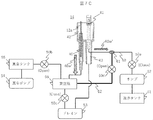
- FIG. 1 It is a figure which shows the whole structure of an automatic analyzer. It is a figure which shows the structure of a washing tank. It is a figure which shows the flow-path structure (1st comparative example) of a washing tank. It is a figure which shows the flow-path structure (2nd comparative example) of a washing tank. It is a figure which shows the flow-path structure (Example 1) of a washing tank. It is a figure which shows operation
- FIG. 1 It is a figure which shows another flow path structure (Example 1) of a washing tank. It is a figure which shows operation
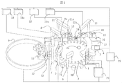
- Fig. 1 is a perspective view of the automatic analyzer.
- the automatic analyzer is an apparatus that dispenses a sample and a reagent into a plurality of reaction vessels 2 and causes them to react with each other, and measures the reacted liquid.
- the automatic analyzer includes a reaction disc 1, a reagent disc 9, a sample transport mechanism 17, a reagent dispensing mechanism 7, 8, a reagent syringe 18, 18a, a sample dispensing mechanism 11, 12, a sample syringe 19, 19a, and a cleaning mechanism. 3, a light source 4a, a spectrophotometer 4, stirring mechanisms 5, 6, a cleaning pump 20, cleaning tanks 13, 14, 30, 31, 32, 33, a vacuum suction port 40, and a controller 21.
- the reaction vessels 1 are arranged on the circumference of the reaction disk 1.
- a sample transport mechanism 17 for moving a rack 16 on which a sample container 15 is placed is installed near the reaction disk 1.
- a test sample (specimen) such as blood is stored in the sample container 15, placed on the rack 16 and transported by the sample transport mechanism 17.
- a sample dispensing mechanism 11 and a sample dispensing mechanism 12, which are rotatable and vertically movable, are installed between the reaction disk 1 and the sample transport mechanism 17.
- the sample dispensing mechanisms 11 and 12 are respectively provided with sample probes 11a and 12a to which sample syringes 19 and 19a are connected, and the sample probes 11a and 12a are arcs about the rotation axes of the sample dispensing mechanisms 11 and 12, respectively. While drawing, the sample is dispensed from the sample container 15 to the reaction container 2.
- a plurality of reagent bottles 10 can be placed on the circumference of the reagent disc 9.
- the reagent disk 9 is kept cold.
- reagent dispensing mechanisms 7 and 8 which are rotatable and vertically movable are installed.
- the reagent dispensing mechanisms 7 and 8 are provided with reagent probes 7a and 8a, respectively, to which reagent syringes 18 and 18a are connected, and the reagent probes 7a and 8a are circular arcs about the rotation axes of the reagent dispensing mechanisms 7 and 8, respectively.
- the reagent disk 9 is accessed to dispense the reagent from the reagent bottle 10 to the reaction container 2.
- a cleaning mechanism 3 for cleaning the measured reaction container stirring mechanisms 5, 6 for stirring the mixed liquid (reaction liquid) of the reagent and sample in the reaction container, and the mixed liquid in the reaction container.
- a light source 4a and a spectrophotometer 4 for irradiating the (reaction liquid) with light and measuring the absorbance thereof are arranged.
- a cleaning pump 20 is connected to the cleaning mechanism 3. Washing tanks 13, 14, 33, 32, 31, and 30 are installed on the operating ranges of the sample dispensing mechanisms 11 and 12, the reagent dispensing mechanisms 7 and 8, and the stirring mechanisms 5 and 6, respectively.
- Each mechanism of the automatic analyzer is connected to and controlled by the controller 21.
- the analysis processing of the inspection sample by the automatic analyzer is executed in the following order.
- the sample in the sample container 15 placed on the rack 16 transported to the vicinity of the reaction disc 1 by the sample transport mechanism 17 is transferred to the reaction container 2 on the reaction disc 1 by the sample probe 11 a of the sample dispensing mechanism 11.
- the reaction container 2 in which the sample used for the analysis is previously dispensed from the reagent bottle 10 on the reagent disk 9 by the reagent probe 7a of the reagent dispensing mechanism 7 or the reagent probe 8a of the reagent dispensing mechanism 8.
- the stirring mechanism 5 stirs the mixed liquid of the sample and the reagent in the reaction container 2.
- the light generated from the light source 4a is transmitted through the reaction container 2 containing the mixed solution, and the luminous intensity of the transmitted light is measured by the spectrophotometer 4.
- the luminous intensity measured by the spectrophotometer 4 is transmitted to the controller 21 via the A/D converter and the interface.
- the controller 21 performs, for example, a calculation for calculating the concentration of a predetermined component of an analysis item corresponding to the reagent and the like from the absorbance of the mixed liquid (reaction liquid).
- the obtained measurement result is displayed on a display unit (not shown) or the like.
- the sample probe 11a that sucks the sample in the sample container 15 is sucked from the upper part of the sample container 15, and the sample probe 12a is sucked from the vicinity of the bottom of the sample container 15.
- the sample probe 12a used for dispensing the sample needs to wash the sample probe extensively in the washing tank 14 in order to prevent contamination between the samples. Since a large amount of cleaning liquid has adhered to the sample probe 12a after performing a wide range of cleaning, the cleaning tank 14 is provided with a vacuum suction port 40, and the cleaning liquid adhering to the sample probe 12a is removed to clean the sample. Prevent it from being diluted with.
- FIG. 2 shows the structure of the cleaning tank 14. A sectional view, a top view and a side view are shown.
- a drainage pipe 43 and a vacuum suction port 40 are provided at the bottom of the tank 42.
- a cleaning liquid discharge port 41 is provided near the tank 42.
- the sample probe 12a is inserted into the tank 42 near the cleaning liquid discharge port 41, and the entire contaminated area outside the sample probe 12a is cleaned while moving the sample probe 12a up and down.
- the cleaning liquid used for cleaning is discharged from the drain pipe 43. After that, the sample probe 12a is moved to the vacuum suction port 40 and lowered and raised to remove the cleaning liquid attached to the sample probe 12a.
- the vacuum suction port 40 when viewed from above the tank 42, the vacuum suction port 40 is provided at a position different from the position where the cleaning liquid is discharged from the cleaning liquid discharge port 41, and the drain pipe 43 discharges the cleaning liquid from the cleaning liquid discharge port 41. It is provided at the position. As a result, the possibility that the inspection sample attached to the outside of the sample probe 12a will enter the vacuum suction port 40 is reduced.
- FIG. 3A shows the flow channel configuration of the cleaning tank 14 (first comparative example).
- the cleaning liquid is stored in the cleaning tank 51, and is supplied to the cleaning liquid discharge port 41 of the cleaning tank 14 by the pump 52.
- a first electromagnetic valve 50a is provided between the pump 52 and the cleaning liquid outlet 41.
- the drainage pipe 43 is connected to the drain 53.
- a vacuum pump 54 and a vacuum tank 55 are provided for vacuum suction, and a second solenoid valve 50b is provided between the vacuum tank 55 and the vacuum suction port 40.
- the cleaning liquid attached to the side surface of the sample probe 12a is directly collected in the vacuum tank 55, and therefore it is necessary to remove the cleaning liquid accumulated in the vacuum tank 55 after repeating the vacuum suction operation repeatedly.
- the second electromagnetic valve 50b since most of the second electromagnetic valve 50b sucks air from the vacuum suction port 40, there is a possibility that dust or the like in the atmosphere may be trapped in the valve portion of the second electromagnetic valve 50b.
- the sealing performance of the valve 50b deteriorates, and while the vacuum pump 54 is making the vacuum tank 55 negative pressure, the second solenoid valve 50b may leak and the vacuum performance may deteriorate.
- FIG. 3B shows another flow path configuration of the cleaning tank 14 (second comparative example).
- the difference from the flow channel configuration of FIG. 3A is that the vacuum bottle 56 is arranged so that the cleaning liquid attached to the side surface of the sample probe 12a does not directly accumulate in the vacuum tank 55.
- the third electromagnetic valve 50c provided between the vacuum bottle 56 and the drain 53 is opened to discharge the cleaning liquid to the drain 53.
- the cleaning liquid can be prevented from accumulating in the vacuum tank 55, but there is a risk that the third solenoid valve 50c will trap dust and the like, as with the second solenoid valve 50b in FIG. 3A. If the sealing performance of the third solenoid valve 50c deteriorates, problems such as a decrease in vacuum suction capacity and backflow of the cleaning liquid from the drain 53 to the vacuum bottle 56 may occur.
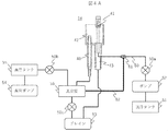
- FIG. 4A shows the flow path configuration of the cleaning tank 14 in the first embodiment.
- a branch 61 is provided in the flow path 60 that sends the cleaning liquid in the cleaning tank 51 to the cleaning liquid discharge port 41 by the pump 52, and the flow path 60 and the vacuum bottle 56 are connected by the bypass flow path 62.
- the vacuum bottle 56 is provided with two channels for the cleaning liquid to flow therein, and in addition to the channel connected to the vacuum suction port 40, it has a channel for allowing the cleaning liquid to flow from the cleaning tank.
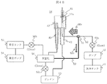
- FIG. 4B shows the operation of the flow channel configuration of the cleaning tank 14 when cleaning the outside of the sample probe 12a.
- the cleaning liquid is discharged from the cleaning liquid discharge port 41 toward the sample probe 12a inserted into the cleaning tank 14, while the vacuum suction operation is not performed.
- the first solenoid valve 50a is opened, the cleaning liquid is discharged from the cleaning liquid discharge port 41.
- the cleaning liquid extruded from the pump 52 into the bypass flow path 62 via the branch 61 flows into the vacuum bottle 56.
- arrows 60v and 62v schematically represent the amounts of the cleaning liquid flowing through the branched flow passage 60 and the bypass flow passage 62, respectively, by their widths.
- the second solenoid valve 50b and the third solenoid valve 50c are set to Close. However, since the vacuum suction port 40 is open to the atmosphere, the cleaning liquid can be easily sent to the vacuum bottle 56 from the bypass channel 62.
- the sample probe 12a In order to remove the cleaning liquid adhering to the side surface of the sample probe 12a, the sample probe 12a is moved to the vacuum suction port 40, the second electromagnetic valve 50b is opened, and then the sample probe 12a is lowered and raised to remove the cleaning liquid. I do.
- the vacuum bottle 56 when the outside of the sample probe 12a is cleaned, the cleaning liquid 60w accumulated from the cleaning liquid outlet 41 to the branch 61 and the cleaning liquid 62w accumulated in the bypass channel 62, and the sample probe 12a
- the cleaning liquid 40w attached to the side surface is drawn into the vacuum bottle 56 by the vacuum suction operation.
- the second solenoid valve 50b Since the diameter of the cleaning liquid discharge port 41 is sufficiently larger than the diameter of the vacuum suction port 40 and most of the vacuum suction port 40 is blocked by the sample probe 12a during vacuum suction, the second solenoid valve 50b is opened. By doing so, the cleaning liquids 60w and 62w can be easily drawn into the vacuum bottle 56.
- the cleaning liquid stored in the vacuum bottle 56 after the drying operation of the sample probe 12a is the sum of the cleaning liquids 62v, 60w, 62w, 40w.
- the cleaning liquid stored in the vacuum bottle 56 in the second comparative example (FIG. 3B) remains in the cleaning liquid 40w.
- the third electromagnetic valve 50c By setting the third electromagnetic valve 50c to Open, it is possible to wash off the valve seat of the third electromagnetic valve 50c with the cleaning liquid stored in the vacuum bottle 56 more than in the comparative example, and dust etc. It is possible to prevent the solenoid valve from malfunctioning.
- the only configuration newly added is the bypass flow passage 62 from the branch 61, which can be realized at low cost.
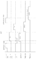
- the time chart of the above operation is shown in Fig. 5.
- This time chart shows the operation in one cycle regarding the cleaning tank 14 defined by the sequence.
- the cleaning liquid remains in the flow path due to the vacuum suction operation.
- the first solenoid valve 50a is opened before the cleaning start timing of the sample probe 12a by the predetermined time 70.
- the flow path is designed so that the cleaning liquid that can wash off the valve seat of the third solenoid valve 50c is stored in the vacuum bottle 56 during one cycle of cleaning and drying the sample probe shown in FIG.
- a restriction may be placed in the bypass flow passage, or the flow amount of the cleaning liquid may be adjustable by a variable throttle.
- the flow path length from the cleaning liquid discharge port 41 to the branch 61 is long, the cleaning liquid accumulated from the cleaning liquid discharge port 41 to the branch 61 while the second solenoid valve 50b is open. It is not necessary to pull everything into the vacuum bottle 56.
- the vacuum bottle 56 has a sufficient amount of cleaning liquid for cleaning the third electromagnetic valve 50c in total during one cycle.
- this operation also applies to the cleaning solution to the vacuum bottle every cycle during the standby cleaning operation or maintenance operation of the sample probe that does not aspirate the sample (specimen).
- the third electromagnetic valve 50c can be washed by storing the gas and discharging it to the drain.
- FIG. 6 shows an example of cleaning the vacuum bottle 56 and the third solenoid valve 50c by utilizing the internal cleaning operation of the sample probe 12a in the maintenance operation.
- FIG. 6 shows a time chart of such a maintenance operation.
- the detergent bottle is installed between the reaction disk 1 and the sample transport mechanism 17, and the sample probe 12a sucks the detergent from the detergent bottle.
- the sample probe 12a After moving to the vacuum suction port 40, the sample probe 12a performs a descending operation. In order to prevent the detergent from scattering around, the sample probe 12a starts discharging after the tip thereof enters the vacuum suction port 40.
- the internal washing time of the sample probe 12a is set to be longer than or equal to the time for removing the detergent in the sample probe 12a.
- the cleaning liquid from the cleaning liquid discharge port 41 to the branch 61 can be stored in the vacuum bottle 56 via the bypass flow passage 62. ..
- the third electromagnetic valve 50c it is possible to flush the valve seat of the third electromagnetic valve 50c by discharging the cleaning liquid accumulated in the vacuum bottle 56 to the drain 53.
- the use of detergent in the internal washing operation is optional, and the washing liquid discharged in the internal washing operation of the sample probe can be performed by performing the same operation in the internal washing operation during the analysis operation of the automatic analyzer. Can be used for the cleaning operation of the solenoid valve. By repeating the above operation, it is possible to keep the third solenoid valve 50c clean and prevent the solenoid valve from malfunctioning due to dust or the like.
- FIG. 7A shows another flow path configuration of the cleaning tank 14 in the first embodiment.
- the difference from the flow path configuration of FIG. 4A is that the fourth electromagnetic valve 50 d is arranged in the bypass flow path 62.
- FIG. 7B shows the operation of the flow path configuration of the cleaning tank 14 when cleaning the outside of the sample probe 12a. Since the first solenoid valve 50a is open, while the fourth solenoid valve 50d is Close, the cleaning liquid does not flow into the bypass passage 62. Accordingly, when the sample probe 12a is washed, the washing water 60v' supplied from the flow path 60 can be entirely used for washing the sample probe 12a without loss of the washing liquid.
- the sample probe 12a is moved to the vacuum suction port 40, the fourth solenoid valve 50d and the second solenoid valve 50b are opened in this order, and then the sample probe 12a is opened.
- the cleaning solution is removed by moving it up and down.
- the vacuum bottle 56 the cleaning liquid 60w′ accumulated from the cleaning liquid outlet 41 to the branch 61 when cleaning the outside of the sample probe 12a and the cleaning liquid 40w′ attached to the side surface of the sample probe 12a are vacuumed.
- the suction operation draws the vacuum bottle 56.
- the cleaning liquid stored in the vacuum bottle 56 after the drying operation of the sample probe 12a is the sum of the cleaning liquids 60w' and 40w', and the cleaning liquid in the case of the second comparative example (FIG. 3B) also in this flow path configuration. More cleaning liquid can be stored in the vacuum bottle 56 as compared with 40w'.
- the third electromagnetic valve 50c after opening the third electromagnetic valve 50c after the completion of the drying operation of the sample probe 12a, it becomes possible to wash off the valve seat of the third electromagnetic valve 50c with the cleaning liquid stored in the vacuum bottle 56, and the dust can be removed. It is possible to prevent the solenoid valve from malfunctioning due to such reasons.
- the cleaning liquid supplied from the cleaning tank 51 is discharged from the cleaning liquid discharge port 41 as it is, the external cleaning time can be further shortened.
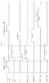
- FIG. 8 A time chart of the above operation is shown in Fig. 8. Except for the control relating to the fourth solenoid valve 50d, it is the same as the time chart of FIG. 5, and therefore redundant description will be omitted. Note that this operation is also applicable to the standby cleaning operation or the maintenance operation of the sample probe that does not suck the sample (sample), other than the cleaning and drying operations of the sample probe that has sucked the sample (sample). ..
- FIG. 9 shows an example of cleaning the vacuum bottle 56 and the third solenoid valve 50c by using the internal cleaning operation of the sample probe 12a in the maintenance operation. It is a time chart which performs the same maintenance operation as FIG. For this reason, except for the control relating to the fourth solenoid valve 50d, it is the same as the time chart of FIG. 6, and thus redundant description will be omitted.
- the fourth solenoid valve 50d is also open so that the cleaning liquid from the cleaning tank 51 can be stored in the vacuum bottle 56 via the bypass flow path 62. To be done.
- the period in which the fourth electromagnetic valve 50d is open is the period in which the first electromagnetic valve 50a is open. It is desirable to have a margin before and after.
- FIG. 10 shows the flow path configuration of the cleaning tank 14 in the second embodiment.
- the flow path configuration of the second embodiment is to provide a flow path 63 for supplying the cleaning liquid in the cleaning tank 51 to the vacuum bottle 56 by the pump 52.
- the first electromagnetic valve 50a is provided in the flow path 60 between the pump 52 and the cleaning liquid discharge port 41, and the pump 52
- a fifth electromagnetic valve 50e is provided in the flow path 63 between the vacuum bottle 56 and the vacuum bottle 56.
- the fifth solenoid valve 50e is controlled so that the cleaning liquid necessary for flushing the valve seat of the third solenoid valve 50c from the washing tank 51 during one cycle is accumulated in the vacuum bottle 56. You can In this flow path configuration, since all the cleaning liquid supplied from the pump 52 is supplied to the vacuum bottle 56, it becomes possible to supply the required amount of cleaning liquid to the vacuum bottle 56 in a short time.
- the time chart in the second embodiment is not particularly shown, the time period in which the fifth solenoid valve 50e is opened during one cycle is the time period in which the cleaning liquid is supplied from the cleaning tank 51 to the cleaning liquid discharge port 41, that is, the probe cleaning. Therefore, it is sufficient to avoid the time zone when the first solenoid valve 50a is open.
- the washing tank for the sample probe has been described as an example, but since it is a technique that can be applied to a configuration requiring a vacuum suction operation after washing the probe, it can also be applied to a washing tank for a reagent probe or the like. Is.
- the sample probe is moved down and up in the cleaning operation after the sample probe is moved to the cleaning liquid discharge port.
- the cleaning liquid attached to the side surface of the sample probe is removed at the vacuum suction position, the effect of the present embodiment is not limited by the cleaning operation of the sample probe.
- Vacuum suction port 41... Cleaning liquid discharge port, 42... Tank, 43... Drain pipe, 50a, 50b, 50c, 50d, 50e... Solenoid valve, 43... Drain pipe, 51... Wash tank, 52... Pump, 53... Drain, 54... Vacuum pump, 55... Vacuum tank, 56... Vacuum bottle, 60: Channel, 61: Branch, 62: Bypass channel, 60v, 60v', 62v, 40w, 40w', 60w, 62w, 62w': Cleaning liquid (flow rate) ), 70: predetermined time.
Landscapes
- Physics & Mathematics (AREA)
- Health & Medical Sciences (AREA)
- Life Sciences & Earth Sciences (AREA)
- Chemical & Material Sciences (AREA)
- Analytical Chemistry (AREA)
- Biochemistry (AREA)
- General Health & Medical Sciences (AREA)
- General Physics & Mathematics (AREA)
- Immunology (AREA)
- Pathology (AREA)
- Automatic Analysis And Handling Materials Therefor (AREA)
Abstract
Description
Claims (13)
- プローブを洗浄するための洗浄液を吐出する洗浄液吐出口と、前記プローブが挿入される真空吸引口とを有する洗浄槽と、
前記洗浄液を溜める洗浄タンクと、
真空タンクと、
前記真空タンクを大気圧と比較して負圧の状態とする真空ポンプと、
前記真空吸引口と前記真空タンクとの間に配置される真空瓶とを有し、
前記真空瓶に前記洗浄液が流入する流路として、前記真空吸引口に接続される第1の流路と前記洗浄タンクに接続される第2の流路とを有する自動分析装置。 - 請求項1において、
前記洗浄槽は、前記洗浄液吐出口から前記洗浄液が吐出される槽を有し、
前記槽の底部に前記真空吸引口が設けられ、前記槽の上から見て、前記真空吸引口は、前記洗浄液吐出口から前記洗浄液が吐出される位置とは異なる位置に設けられている自動分析装置。 - 請求項1において、
前記洗浄タンクに溜められた前記洗浄液を前記洗浄液吐出口に供給するポンプと、
前記ポンプと前記洗浄液吐出口との間に設けられる第1の電磁弁と、
前記真空タンクと前記真空瓶との間に設けられる第2の電磁弁と、
前記真空瓶とドレインとの間に設けられる第3の電磁弁とを有する自動分析装置。 - 請求項3において、
前記第2の流路は、前記第1の電磁弁と前記洗浄液吐出口との間の流路上の分岐と前記真空瓶とを接続するバイパス流路である自動分析装置。 - 請求項4において、
前記バイパス流路上に設けられる第4の電磁弁を有する自動分析装置。 - 請求項3において、
前記第2の流路は前記ポンプと前記真空瓶とを接続する流路であり、前記第2の流路上に第5の電磁弁が設けられる自動分析装置。 - 請求項4において、
コントローラを有し、
前記コントローラは、シーケンスで定められた前記プローブの洗浄開始タイミングに所定時間先立って前記第1の電磁弁を開く自動分析装置。 - 請求項7において、
前記コントローラは、前記第2の電磁弁を開いて前記真空吸引口に前記プローブを挿入し、前記プローブを上下させて前記プローブの外側に付着した前記洗浄液を除去する自動分析装置。 - 請求項8において、
前記コントローラは、前記プローブを前記真空吸引口から移動した後に、前記第3の電磁弁を開く自動分析装置。 - 請求項7において、
前記コントローラは、前記プローブを前記真空吸引口に移動させて、前記プローブの内側を洗浄する内洗動作を行わせる自動分析装置。 - 請求項10において、
前記コントローラは、前記プローブに洗剤を吸引させて内洗動作を行わせる自動分析装置。 - 請求項10において、
前記コントローラは、前記プローブの内洗動作中に、前記第1の電磁弁を開く自動分析装置。 - 請求項1において、
前記プローブはサンプルプローブである自動分析装置。
Priority Applications (4)
| Application Number | Priority Date | Filing Date | Title |
|---|---|---|---|
| US17/276,952 US12360132B2 (en) | 2019-02-18 | 2020-01-30 | Automatic analyzer |
| JP2021501787A JP6998492B2 (ja) | 2019-02-18 | 2020-01-30 | 自動分析装置 |
| CN202080005946.0A CN113039440B (zh) | 2019-02-18 | 2020-01-30 | 自动分析装置 |
| EP20758550.6A EP3929592B1 (en) | 2019-02-18 | 2020-01-30 | Automated analyzer |
Applications Claiming Priority (2)
| Application Number | Priority Date | Filing Date | Title |
|---|---|---|---|
| JP2019-026313 | 2019-02-18 | ||
| JP2019026313 | 2019-02-18 |
Publications (1)
| Publication Number | Publication Date |
|---|---|
| WO2020170751A1 true WO2020170751A1 (ja) | 2020-08-27 |
Family
ID=72144241
Family Applications (1)
| Application Number | Title | Priority Date | Filing Date |
|---|---|---|---|
| PCT/JP2020/003384 Ceased WO2020170751A1 (ja) | 2019-02-18 | 2020-01-30 | 自動分析装置 |
Country Status (5)
| Country | Link |
|---|---|
| US (1) | US12360132B2 (ja) |
| EP (1) | EP3929592B1 (ja) |
| JP (1) | JP6998492B2 (ja) |
| CN (1) | CN113039440B (ja) |
| WO (1) | WO2020170751A1 (ja) |
Cited By (2)
| Publication number | Priority date | Publication date | Assignee | Title |
|---|---|---|---|---|
| WO2024236901A1 (ja) * | 2023-05-15 | 2024-11-21 | 株式会社日立ハイテク | 自動分析装置 |
| US12226776B2 (en) | 2021-11-04 | 2025-02-18 | Instrumentation Laboratory Company | Preparing substances in a medical diagnostic system |
Citations (12)
| Publication number | Priority date | Publication date | Assignee | Title |
|---|---|---|---|---|
| JPS5357893U (ja) * | 1976-10-16 | 1978-05-17 | ||
| JPH0478558U (ja) * | 1990-11-21 | 1992-07-08 | ||
| JPH06167504A (ja) * | 1992-11-26 | 1994-06-14 | Shimadzu Corp | 生化学自動分析装置の洗浄装置 |
| JP2002340913A (ja) * | 2001-05-16 | 2002-11-27 | Hitachi Ltd | 自動分析装置 |
| JP2005257491A (ja) * | 2004-03-12 | 2005-09-22 | Hitachi High-Technologies Corp | 自動分析装置 |
| JP2005308506A (ja) | 2004-04-21 | 2005-11-04 | Hitachi High-Technologies Corp | 自動分析装置 |
| JP2008503721A (ja) * | 2004-06-17 | 2008-02-07 | アボット・ラボラトリーズ | プローブ洗浄カップおよび方法 |
| US20080099057A1 (en) * | 2006-10-27 | 2008-05-01 | Dade Behring Inc. | Method and Device for Cleaning a Liquid Aspiration and Dispense Probe |
| WO2014112591A1 (ja) * | 2013-01-21 | 2014-07-24 | 株式会社日立ハイテクノロジーズ | 自動分析装置 |
| WO2017145672A1 (ja) * | 2016-02-24 | 2017-08-31 | 株式会社日立ハイテクノロジーズ | 自動分析装置および洗浄方法 |
| WO2018155042A1 (ja) * | 2017-02-24 | 2018-08-30 | 株式会社日立ハイテクノロジーズ | 自動分析装置 |
| JP2018159682A (ja) * | 2017-03-24 | 2018-10-11 | 株式会社日立ハイテクノロジーズ | 自動分析装置 |
Family Cites Families (3)
| Publication number | Priority date | Publication date | Assignee | Title |
|---|---|---|---|---|
| CA2132270A1 (en) * | 1993-10-28 | 1995-04-29 | Erich Lerch | Automatic pipetting apparatus having a cleaning device |
| CN203299211U (zh) * | 2013-06-18 | 2013-11-20 | 东软安德医疗科技有限公司 | 一种全自动生化分析仪给排液系统 |
| CN105934676B (zh) * | 2014-01-27 | 2017-09-22 | 株式会社日立高新技术 | 自动分析装置 |
-
2020
- 2020-01-30 US US17/276,952 patent/US12360132B2/en active Active
- 2020-01-30 EP EP20758550.6A patent/EP3929592B1/en active Active
- 2020-01-30 JP JP2021501787A patent/JP6998492B2/ja active Active
- 2020-01-30 CN CN202080005946.0A patent/CN113039440B/zh active Active
- 2020-01-30 WO PCT/JP2020/003384 patent/WO2020170751A1/ja not_active Ceased
Patent Citations (12)
| Publication number | Priority date | Publication date | Assignee | Title |
|---|---|---|---|---|
| JPS5357893U (ja) * | 1976-10-16 | 1978-05-17 | ||
| JPH0478558U (ja) * | 1990-11-21 | 1992-07-08 | ||
| JPH06167504A (ja) * | 1992-11-26 | 1994-06-14 | Shimadzu Corp | 生化学自動分析装置の洗浄装置 |
| JP2002340913A (ja) * | 2001-05-16 | 2002-11-27 | Hitachi Ltd | 自動分析装置 |
| JP2005257491A (ja) * | 2004-03-12 | 2005-09-22 | Hitachi High-Technologies Corp | 自動分析装置 |
| JP2005308506A (ja) | 2004-04-21 | 2005-11-04 | Hitachi High-Technologies Corp | 自動分析装置 |
| JP2008503721A (ja) * | 2004-06-17 | 2008-02-07 | アボット・ラボラトリーズ | プローブ洗浄カップおよび方法 |
| US20080099057A1 (en) * | 2006-10-27 | 2008-05-01 | Dade Behring Inc. | Method and Device for Cleaning a Liquid Aspiration and Dispense Probe |
| WO2014112591A1 (ja) * | 2013-01-21 | 2014-07-24 | 株式会社日立ハイテクノロジーズ | 自動分析装置 |
| WO2017145672A1 (ja) * | 2016-02-24 | 2017-08-31 | 株式会社日立ハイテクノロジーズ | 自動分析装置および洗浄方法 |
| WO2018155042A1 (ja) * | 2017-02-24 | 2018-08-30 | 株式会社日立ハイテクノロジーズ | 自動分析装置 |
| JP2018159682A (ja) * | 2017-03-24 | 2018-10-11 | 株式会社日立ハイテクノロジーズ | 自動分析装置 |
Non-Patent Citations (1)
| Title |
|---|
| See also references of EP3929592A4 |
Cited By (2)
| Publication number | Priority date | Publication date | Assignee | Title |
|---|---|---|---|---|
| US12226776B2 (en) | 2021-11-04 | 2025-02-18 | Instrumentation Laboratory Company | Preparing substances in a medical diagnostic system |
| WO2024236901A1 (ja) * | 2023-05-15 | 2024-11-21 | 株式会社日立ハイテク | 自動分析装置 |
Also Published As
| Publication number | Publication date |
|---|---|
| JPWO2020170751A1 (ja) | 2021-10-07 |
| JP6998492B2 (ja) | 2022-01-18 |
| EP3929592B1 (en) | 2024-11-27 |
| CN113039440A (zh) | 2021-06-25 |
| CN113039440B (zh) | 2024-11-26 |
| EP3929592A1 (en) | 2021-12-29 |
| US12360132B2 (en) | 2025-07-15 |
| EP3929592A4 (en) | 2022-10-26 |
| US20220034926A1 (en) | 2022-02-03 |
Similar Documents
| Publication | Publication Date | Title |
|---|---|---|
| JP6647288B2 (ja) | 自動分析装置及び方法 | |
| US7621282B2 (en) | Probe washing cups and methods | |
| JP6466846B2 (ja) | ノズル洗浄方法及び自動分析装置 | |
| CN103348251B (zh) | 自动分析装置 | |
| JP6517565B2 (ja) | 分注ノズル洗浄方法および自動分析装置 | |
| CN111133317B (zh) | 自动分析装置以及自动分析装置的流路堵塞检测方法 | |
| JP2009042067A (ja) | 自動分析装置 | |
| JPWO2014112591A1 (ja) | 自動分析装置 | |
| WO2010098053A1 (ja) | 化学分析装置 | |
| JP2011106828A (ja) | 分注装置、自動分析装置及び分注方法 | |
| JP7110222B2 (ja) | 自動分析装置およびプローブの洗浄方法 | |
| WO2018155042A1 (ja) | 自動分析装置 | |
| WO2020170751A1 (ja) | 自動分析装置 | |
| US20220057422A1 (en) | Automated Analyzer | |
| JP4175916B2 (ja) | 自動分析装置 | |
| WO2022224521A1 (ja) | 自動分析装置とその制御方法 | |
| JP3717859B2 (ja) | 化学分析装置 | |
| WO2020230403A1 (ja) | 自動分析装置 | |
| JP2011095058A (ja) | 生化学分析装置及び分注処理方法 | |
| JP3282248B2 (ja) | 生化学自動分析装置の洗浄装置 | |
| JP2003294773A (ja) | 臨床検査自動分析装置、臨床検査自動分析装置の洗浄方法 | |
| JP3047365B2 (ja) | 生化学自動分析装置の洗浄装置 | |
| US12174210B2 (en) | Automated analyzer and cleaning method | |
| JP5372646B2 (ja) | 自動分析装置 | |
| JPH03230000A (ja) | 液体の減圧吸引装置 |
Legal Events
| Date | Code | Title | Description |
|---|---|---|---|
| 121 | Ep: the epo has been informed by wipo that ep was designated in this application |
Ref document number: 20758550 Country of ref document: EP Kind code of ref document: A1 |
|
| DPE1 | Request for preliminary examination filed after expiration of 19th month from priority date (pct application filed from 20040101) | ||
| ENP | Entry into the national phase |
Ref document number: 2021501787 Country of ref document: JP Kind code of ref document: A |
|
| NENP | Non-entry into the national phase |
Ref country code: DE |
|
| ENP | Entry into the national phase |
Ref document number: 2020758550 Country of ref document: EP Effective date: 20210920 |
|
| WWG | Wipo information: grant in national office |
Ref document number: 17276952 Country of ref document: US |