WO2020170760A1 - コイル接合体およびコイル接合体の製造方法 - Google Patents
コイル接合体およびコイル接合体の製造方法 Download PDFInfo
- Publication number
- WO2020170760A1 WO2020170760A1 PCT/JP2020/003626 JP2020003626W WO2020170760A1 WO 2020170760 A1 WO2020170760 A1 WO 2020170760A1 JP 2020003626 W JP2020003626 W JP 2020003626W WO 2020170760 A1 WO2020170760 A1 WO 2020170760A1
- Authority
- WO
- WIPO (PCT)
- Prior art keywords
- coil
- bus bar
- metal member
- manufacturing
- joint
- Prior art date
- Legal status (The legal status is an assumption and is not a legal conclusion. Google has not performed a legal analysis and makes no representation as to the accuracy of the status listed.)
- Ceased
Links
Images


Classifications
-
- H—ELECTRICITY
- H02—GENERATION; CONVERSION OR DISTRIBUTION OF ELECTRIC POWER
- H02K—DYNAMO-ELECTRIC MACHINES
- H02K15/00—Processes or apparatus specially adapted for manufacturing, assembling, maintaining or repairing of dynamo-electric machines
- H02K15/30—Manufacture of winding connections
- H02K15/33—Connecting winding sections; Forming leads; Connecting leads to terminals
- H02K15/35—Form-wound windings
-
- H—ELECTRICITY
- H01—ELECTRIC ELEMENTS
- H01F—MAGNETS; INDUCTANCES; TRANSFORMERS; SELECTION OF MATERIALS FOR THEIR MAGNETIC PROPERTIES
- H01F5/00—Coils
-
- H—ELECTRICITY
- H02—GENERATION; CONVERSION OR DISTRIBUTION OF ELECTRIC POWER
- H02K—DYNAMO-ELECTRIC MACHINES
- H02K15/00—Processes or apparatus specially adapted for manufacturing, assembling, maintaining or repairing of dynamo-electric machines
- H02K15/04—Processes or apparatus specially adapted for manufacturing, assembling, maintaining or repairing of dynamo-electric machines of windings prior to their mounting into the machines
- H02K15/0414—Processes or apparatus specially adapted for manufacturing, assembling, maintaining or repairing of dynamo-electric machines of windings prior to their mounting into the machines the windings consisting of separate elements, e.g. bars, segments or half coils
-
- H—ELECTRICITY
- H02—GENERATION; CONVERSION OR DISTRIBUTION OF ELECTRIC POWER
- H02K—DYNAMO-ELECTRIC MACHINES
- H02K3/00—Details of windings
- H02K3/02—Windings characterised by the conductor material
-
- H—ELECTRICITY
- H02—GENERATION; CONVERSION OR DISTRIBUTION OF ELECTRIC POWER
- H02K—DYNAMO-ELECTRIC MACHINES
- H02K3/00—Details of windings
- H02K3/04—Windings characterised by the conductor shape, form or construction, e.g. with bar conductors
-
- H—ELECTRICITY
- H02—GENERATION; CONVERSION OR DISTRIBUTION OF ELECTRIC POWER
- H02K—DYNAMO-ELECTRIC MACHINES
- H02K3/00—Details of windings
- H02K3/04—Windings characterised by the conductor shape, form or construction, e.g. with bar conductors
- H02K3/18—Windings for salient poles
-
- H—ELECTRICITY
- H02—GENERATION; CONVERSION OR DISTRIBUTION OF ELECTRIC POWER
- H02K—DYNAMO-ELECTRIC MACHINES
- H02K3/00—Details of windings
- H02K3/46—Fastening of windings on the stator or rotor structure
- H02K3/52—Fastening salient pole windings or connections thereto
- H02K3/521—Fastening salient pole windings or connections thereto applicable to stators only
- H02K3/522—Fastening salient pole windings or connections thereto applicable to stators only for generally annular cores with salient poles
-
- H—ELECTRICITY
- H01—ELECTRIC ELEMENTS
- H01F—MAGNETS; INDUCTANCES; TRANSFORMERS; SELECTION OF MATERIALS FOR THEIR MAGNETIC PROPERTIES
- H01F27/00—Details of transformers or inductances, in general
- H01F27/28—Coils; Windings; Conductive connections
- H01F27/2847—Sheets; Strips
-
- H—ELECTRICITY
- H02—GENERATION; CONVERSION OR DISTRIBUTION OF ELECTRIC POWER
- H02K—DYNAMO-ELECTRIC MACHINES
- H02K2203/00—Specific aspects not provided for in the other groups of this subclass relating to the windings
- H02K2203/09—Machines characterised by wiring elements other than wires, e.g. bus rings, for connecting the winding terminations
Definitions
- the present invention relates to a coil bonded body and a method for manufacturing the coil bonded body.
- stator stator
- stator stator
- slots slots
- a coil member for example, a copper wire
- the coil arranged annularly is configured so that both ends (starting end and end) of the winding are projected to one side (for example, above) in the axial direction of the stator core, and the both ends are directly Alternatively, it is connected via a connecting member to a wiring member such as a rod-shaped (arc-shaped) or annular bus bar extending in the circumferential direction of the stator core by welding or screwing (see, for example, Patent Documents 1 and 2).
- connection method by welding or screwing has a limit to the miniaturization of the completed stator because the structure of the joint becomes complicated. Further, a device for connecting the wiring member (bus bar) to the coil after the coil is attached to the stator core is required, which causes a problem that the manufacturing device of the stator becomes large and the connecting work becomes complicated.
- the present invention simplifies the configuration of the coil and the wiring member (bus bar) connecting portion, simplifies the number of components and the connecting process, suppresses an increase in resistance in the connecting portion, and improves the connection state.
- An object of the present invention is to provide a coil assembly and a method for manufacturing the same.
- the present invention includes a coil made of a first metal member to be wound, and a bus bar made of a second metal member connected to an end portion of the winding of the coil, and a joint portion between the end portion and the bus bar.
- a coil-bonded body characterized by being formed by pressure welding with end faces abutting each other.
- the present invention provides a step of preparing a coil made of a first metal member to be wound and a bus bar made of a second metal member, and abutting ends of the coil and end faces of the end of the bus bar. And press-contacting with each other to form a bonded portion.
- the structure of a coil and a wiring member (bus bar) connection part is simplified, a number of components and a connection process are simplified, an increase in resistance in a connection part is suppressed, and the connection state which can be made favorable is also provided. And the manufacturing method for the same can be provided.
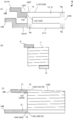
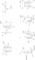
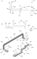
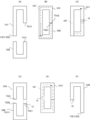
- FIG. 1 It is the schematic which shows the external appearance of the coil assembly of this embodiment, (A) front view, (B) side view, (C) side view. It is a figure explaining the coil of this embodiment, (A) front view of a coil, (B) front view of a coil piece, (C) sectional view of a coil piece, (D)-(G) front view of a coil piece. Is. It is a figure which shows the outline of the bus-bar of this embodiment, and is (A) front view, (B) side view, (C) perspective view, (D) perspective view. It is a figure which shows the outline of the bus-bar of this embodiment, and is a (A) front view, a (B) front view, and a (C) perspective view.
- FIG. 1 is a schematic external view of a coil assembly 10 of the present embodiment.
- FIG. 1A is a front view seen from the spiral axis direction
- FIG. 1B is the left direction in FIG. 1A.
- FIG. 3C is a side view seen from above
- FIG. 6C is a side view seen from below in FIG.
- FIG. 2 is a diagram showing an example of the coil 11 (spiral structure 50) and the flat conductor C (C0) of the coil 11 according to the present embodiment.
- FIG. 2A shows the coil 11 (spiral structure in a completed state). It is the front view which looked at the body 50) from the axial direction of the spiral structure, the same figure (B) is a front view of the flat conductor C, and the same figure (C) shows the XX sectional view of the same figure (B).
- FIGS. 7D to 7G are front views showing an example of the shape of the flat conductor C.
- FIG. 3 is a schematic diagram showing the bus bar 12.
- 1A to 1C are front views of the bus bar 12 corresponding to FIG. 1A, and
- FIG. 1D is a side view corresponding to FIG. 1C.
- the coil assembly 10 of the present embodiment includes a coil 11 made up of a first metal member 13 and a bus bar 12 made up of a second metal member 14 to be wound.
- the coil bonded body 10 of the present embodiment is one in which a bus bar (wiring member) 12 having an arbitrary shape is pressure-welded to a winding end 11E of the coil 11 (hereinafter, referred to as a coil end 11E).
- a bus bar wiring member
- the coil assembly 10 of the present embodiment will be referred to as a coil 10 with a bus bar.
- the coil 11 has a pair of coil end portions 11E (starting end portion 11ES and terminating end portion 11EE), and the bus bar 12 is connected to at least one of the coil end portions 11E.
- the coil 10 with a bus bar will be described by taking a configuration in which the bus bar 12 is connected to both of the coil end portions 11E (the start end portion 11ES and the end portion 11EE) of the coil 11.
- the shape of the bus bar 12 is arbitrary and is not limited to the illustrated shape. Further, in this example, the busbars 12 have the same configuration (shape), but the busbars 12 respectively connected to the starting end portion 11ES and the terminating end portion 11EE may have different shapes. Further, the bus bar 12 may be connected to any one of the coil end portions 11E (starting end portion 11ES or terminating end portion 11EE).
- the member of the coil 11 is a lightweight metal here, for example, aluminum (Al).
- the member (second metal member 14) of the bus bar 12 is a metal different from the first metal member 13 in this example, and is preferably a metal having high conductivity, for example, copper (Cu). ..
- the first metal member 13 and the second metal member 14 may be metal members of the same type (for example, copper).
- the coil 11 of the present embodiment is attached to a tooth portion of a stator core to form a stator (stator).
- all of the winding portions of the spiral structure of one coil 11 are one tooth portion. It is wound so that it can be attached to.
- the coil 11 is a so-called concentrated winding coil that is wound such that the axes of the spiraling portions of the spiral structure substantially match (the spiraling portions substantially overlap in the spiral axis direction of the coil 11 ).
- the coil 11 is a so-called edgewise coil formed by winding a flat conductor, and more specifically, a plurality of strip-shaped flat conductors (coil pieces) each having a linear portion are continuously connected.
- the spiral structure 50 is formed.
- the configuration of the coil 11 will be further described with reference to FIG.
- a plurality of strip-shaped flat conductors C are connected at their straight portions along the strip longitudinal direction (spiral advancing direction), and the flat conductors C in the spiral advancing direction are connected.
- the end faces are butted against each other and pressed (pressure contact, for example, cold pressure contact), and the spiral structure 50 is continuously formed so as to obtain a desired number of turns.
- a region for one round of the spiral structure 50 hereinafter, referred to as a region for one round CR
- the corners of the winding are substantially right angles
- the front view seen from the axial direction of the spiral structure 50 see FIG.
- both the outer peripheral side and the inner peripheral side are (substantially) rectangular.
- the flat conductor C forming the coil 11 is also referred to as a coil piece C in the following description.
- the flat conductor (coil piece) C of the present embodiment is, for example, a direction (a band short direction) intersecting (orthogonal) with a straight line portion in the band longitudinal direction BL (the traveling direction of the spiral structure).
- the cut surface (cross section along line XX) when cut into the BS) is a rectangular or rounded rectangular conductor as shown in FIG. That is, the coil piece C is a strip-shaped member that has two wide surfaces WS that face each other and two narrow surfaces WT that face each other, and is long in a predetermined direction.
- the end surface TS of the coil 11 is a coil end 11E (starting end 11ES and terminating end that is parallel to the cut surface when cut in a direction intersecting (orthogonal) with a straight line portion extending in the traveling direction (longitudinal direction of the band) of the spiral structure. Part 11EE).
- each flat conductor (coil piece) C is obtained by punching an aluminum plate (for example, a thickness of about 0.1 mm to 5 mm) into a desired shape. And has at least a straight portion STR. More specifically, the coil piece C has a straight portion and at least one direction changing portion TN.
- the direction changing portion TN is a portion bent so as to change the extending direction of the strip longitudinal direction. More specifically, the coil piece C includes a first straight line portion STR1 extending in the first direction along the strip longitudinal direction, a second straight line portion STR2 extending in the second direction, and a first straight line portion STR1. It has at least the direction changing part TN arranged between the second straight part STR2.
- the straight line portion STR (the first straight line portion STR1 and the second straight line portion STR2) is a portion that is continuous with the end surface TS and that has a straight line region that is longer than the pressure contact amount by pressing (pressing length).
- the coil piece C having the direction changing portion TN is bent in the same direction along the longitudinal direction of the strip (always rightward or leftward in plan view) so as to have a spiral shape when continuous. To do. Further, it is desirable that at least one (preferably all) of the direction changing portions TN is a non-curved (for example, substantially right angle) shape corner portion. In this example, the direction changing portion TN is a substantially square area, as shown by hatching in FIG. Further, the end surface TS of the coil piece C of the present embodiment is assumed to be located on the straight line portion of the coil piece C excluding the direction changing portion TN.
- the direction changing portion TN has one L-shape (FIG. (D)), the direction changing portion TN has two U-shapes (FIG. (E)), and direction change.
- the part TN has three C-shapes (FIG. (F)) and the direction changing part TN has four C-shapes (FIG. (G)).
- all the coil pieces C may have the same shape, or may have a combination of at least one of the shapes shown in (D) to (G) of FIG.
- a combination of a coil piece C having at least one of the shapes shown in (D) to (G) and a linear (I-shaped coil piece C having no direction changing portion TN) may be used.
- the direction changing portion TN may be four O-shaped coil pieces C.
- all the coil pieces C are U-shaped as shown in FIG. A case will be described as an example.
- a plurality of such flat conductors C are joined by pressure welding (for example, cold pressure welding) by abutting the end faces TS in the spiral traveling direction. That is, the coil 11 is joined to the spiral structure 50 (one-circle region CR) by the pressure contact with the linear portion STR except the direction changing portion TN (shown by dot hatching in FIG. (See (A)) is provided (the joining portion 15 is not included in the direction changing portion TN (corner portion)).
- pressure welding for example, cold pressure welding
- each coil end portion 11E has a coil straight portion 11ST.
- the coil straight line portion 11ST is a straight line region that is continuous with the end surface TS of the coil 11 and extends along the pressing direction P in the step of pressing (pressing contact), and the length of the straight line region is greater than the pressing length (pressing contact amount) CPL. Is also a long part.
- the pressing length CPL is a length shortened in the pressing process, which will be described later.
- the coil straight portion 11ST is also the straight portion STR of the unit coil piece C.
- the joint 15 is shown by a broken line for convenience of description, but in the case of cold pressure welding in particular, the joint 15 is a metal atomic bond, and therefore the joint 15 is difficult to recognize by visual inspection of its appearance (substantially visible). It is firmly joined together to the extent that it becomes impossible). As a result, the stability of the joint 15 is overwhelmingly improved as compared with a configuration in which a plurality of coil pieces C are connected in plane by an adhesive material (fixing material, brazing, etc.) or connected by welding or the like. You can
- the shape of the coil 11 in plan view (part (A) in the figure) (particularly the shape on the inner peripheral side) can be made substantially rectangular, for example, when the coil 11 is attached to the stator of the motor, the space factor of the coil 11 is increased. Can be increased. As a result, it is possible to reduce the resistance and increase the efficiency of the motor that employs the coil 11.
- the weight of the coil 11 made of aluminum can be reduced to 1/3 and the cost can be reduced to 1/3 as compared with a coil of the same shape made of copper, for example.
- FIGS. 4A and 4B are front views corresponding to FIG. 1A of the bus bar 12, and FIG. 4C is a perspective view.
- the bus bar 12 is a wiring member that connects the coil 11 and an external configuration of the coil 11 (for example, another wiring member (another bus bar), another component, a terminal, etc.). It has a first end 12A that is connected to the coil end 11E and a second end 12B that is connected to an external component, and is made of a metal member having good conductivity such as copper. The end face 12AS is exposed at the first end 12A and the end face 12BS is exposed at the second end 12B.
- the shape of the bus bar 12 is arbitrary according to the configuration of the lead-out side of the coil 11, but for example, as shown in FIG. 7A, the shape of the first end 12A on the side connected to the coil end 11E is the coil.
- the shape of the flat conductor may be the same as that of the end portion 11E, and the second end portion 12B may have a different shape such as a flat conductor that is thinner (thicker) than the first end portion 12A.
- one or a plurality of bent portions 12D may be included in the two-dimensional plane, and FIGS. ), one or a plurality of bent portions 12D may be included in the three-dimensional space, and the bent portion 12D in the two-dimensional space and the bent portion 12D in the three-dimensional space may be combined. It may be configured.
- the second end 12B may be provided with a terminal (or an engaging portion) 20 having another structure.
- a terminal or an engaging portion 20 having another structure.
- the bus bar 12 and the terminal 20 are the same metal member (for example, copper) is illustrated.
- the bus bar 12 and the terminal 20 may be different metal members.
- the bus bar 12 may be the same first metal member 13 (for example, aluminum) as the coil 11, and the terminal 20 may be a different metal member (for example, copper).
- the shape of the first end 12A may be a flat conductor shape equivalent to that of the coil end 11E, and the second end 12B may be a different shape such as a round wire. ..
- a curved portion 12E may be included.
- the structure may be bent (branched) in a plurality of directions so that a plurality of end portions 12B and 12X exist in addition to the first end portion 12A.
- the terminal 20 may be connected to at least one of the second end 12B and the other end 12X.
- these (at least one of FIG. 3 and FIG. 4 may be combined.
- the bus bar 12 is configured to include a bus bar wiring portion 12W connecting (between) the first end 12A and the second end 12B.
- the busbar wiring portion 12W includes at least the busbar straight portion 12ST.
- the bus bar linear portion 12ST of the present embodiment has a linear region which is continuous with the first end 12A and extends along the pressing direction P in the pressing (pressing) step, and the length of the linear region is pressed. It is a region longer than the length (pressure contact amount) CPL.
- the busbar wiring portion 12W may have another busbar straight portion 12ST' in addition to the busbar straight portion ST.
- the busbar wiring portion 12W has a shape including only the busbar straight portion 12ST (FIG. 4A), or a shape including the busbar straight portion 12ST and another busbar straight portion 12ST' and at least one direction changing portion TN (FIG. 3, FIG. 4(B), FIG. 4(C)), or at least any combination of the shapes shown in FIGS. 3 and 4.
- the direction changing portion TN is a portion that is bent (curved) so as to change the extending direction of the strip longitudinal direction (direction serving as the current path). More specifically, when the busbar wiring portion 12D has a bent shape (FIGS. 3, 4B, and 4C), the busbar wiring portion 12W has two straight lines extending in different directions in the current path. At least a part (for example, a busbar straight line portion 12ST extending in the first direction and another busbar straight line portion 12ST' extending in the second direction) and a direction changing portion TN arranged therebetween are provided. (There may also be a direction change section TN between two different other bus bar straight sections 12ST' and between them).
- the curved portion 12E shown in FIG. 4B is a part of the direction changing portion TN.
- the second end 12B and the other end 12X pass from the first end 12A through the direction changing part TN so as to have a substantially T shape in a side view. It has a branched structure and is pressed downward in the figure. Therefore, the first end portion 12A is provided with the bus bar straight portion 12ST, which is longer than the pressing amount CPL, along the pressing direction P.
- the coil end portion 11E and the first end portion 12A of the bus bar 12 are directly butted and joined. Specifically, as shown in FIG. 1(A), the end surface TS of the coil straight portion 11ST of the coil end portion 11E and the end surfaces 12AS of the bus bar straight portion 12ST of the first end portion 12A are butted against each other and pressed (for example, cold (Press contact) to form the joint portion 16.
- the end surface 12AS of the bus bar 12 is an end surface parallel to the cut surface when the first end portion 12A (bus bar straight portion 12ST) is cut in a direction intersecting (orthogonal to) the pressing direction P in the pressing step. is there.
- the joining portion 16 formed by press-contacting the coil end portion 11E and the first end portion 12A of the bus bar 12 has the straight portion 10ST in the coil 10 with bus bar after joining (the straight portion 10ST excluding the direction changing portion TN of the coil 10 with bus bar). ) Is formed.
- the joining portion 16 exists at a position not included in the direction changing portion TN (corner portion) in the coil 10 with the bus bar (FIG. 1(A)).
- the first end 12A of the bus bar 12 is configured such that the end surface 12AS has a shape (size) that matches the shape of the coil piece C of the coil end 11E, for example.
- the end surface 12AS of the first end portion 12A (busbar straight portion 12ST) is rectangular so as to substantially match the shape (the rectangular shape in this example) of the end surface TS of the coil straight portion 11ST of the coil end portion 11E.
- the shapes are the same (rectangular shapes that are substantially the same).
- the shape of (the end surface 12BS of) the second end portion 12B is arbitrarily selected according to the shape of the wiring or the like to be connected.
- the joint portion 16 is clearly indicated by a dotted line for convenience of description. However, in the case of cold pressure welding, the joint portion 16 has a position where the end surface TS of the coil end portion 11E and the end surface 12AS of the bus bar 12 are visually observed. They are securely joined together to the extent that they are difficult to recognize (substantially invisible).
- the coil 11 (first metal member 13) is, for example, aluminum and the bus bar 12 (second metal member 14) is, for example, copper as in the example of the present embodiment
- aluminum is likely to have an oxide film and is deformed. Since it is easy, joining by soldering (brazing) or general welding causes problems such as creep deformation and insufficient joining strength, especially when used in a large current region. Alternatively, even with welding, a special method or device is required to obtain a sufficient joint strength, and this cannot be easily performed. For this reason, conventionally, the joining of the both has often been performed by screwing or the like.
- the bus bar 12 and the coil 11 are directly pressure-contacted to each other, the bus bar 12 and the coil 11 are connected to each other by an adhesive material (fixing material, brazing, etc.), or by welding or screwing. It is possible to overwhelmly improve the stability of the portion 16 and obtain sufficient connection strength.
- the coil 11 and the bus bar 12 can be integrally (continuously and smoothly) connected to each other, the structure of the joint portion 16 can be prevented from becoming complicated as compared with the case where the both are joined by welding, bonding, screwing or the like. (The joint portion 16 can be made to have the minimum necessary configuration), and an increase in resistance at the joint portion 16 can be suppressed.
- the joint 21 between the aluminum bus bar 12 and the copper terminal 20 shown in FIGS. 3D and 4C and the like is similar to the joint 16 between the coil 11 and the bus bar 12 described in the present embodiment. It is composed of pressure welding (cold pressure welding). That is, the end surface of the second end portion 1B of the bus bar 12 and the end surface of the terminal 20 on the bus bar 12 side are butted (cold) and pressure-welded to each other.
- the coil 11 is made of, for example, a lightweight first metal member 13 (for example, aluminum), and the bus bar 12 has the second metal member 14 having good conductivity.
- the second metal member 14 having good conductivity.
- the cost can be reduced to 1/3 and the weight can be reduced to 1/3.
- the coil 11 and the bus bar 12 are made of different materials, sufficient joining strength can be obtained. Therefore, it can be used in a large current region, and when the coil is used in a motor or the like, it is lightweight and inexpensive, and further high efficiency can be achieved.
- the coil 11 and the bus bar 12 can be unitized, for example, in the manufacturing process of the stator (motor), if the coil 10 with the bus bar of the present embodiment is attached to the stator core, the connecting process of the coil and the bus bar becomes unnecessary.
- a device for connecting the coil to the stator a device for connecting the coil and the bus bar
- the stator manufacturing device can be downsized and the stator manufacturing process can be simplified.
- the same effect is obtained not only when the first metal member 13 and the second metal member 14 are different materials but also when the same material (for example, copper) is used.
- the coil 11 is coated with resin with the bus bar 12 exposed.
- FIG. 5 is a schematic front view of the coil piece C as viewed from the spiral axis direction of the coil 11.
- FIG. 6 is a view showing a connection state of the coil 11 and the bus bar 12, and
- FIGS. 6A to 6C are schematic front views of the coil piece C and the bus bar 12 viewed from the spiral axis direction of the coil 11.
- the same figure (D) is the same as the figure (A)
- the figure (E) is the figure (B)
- the figure (F) and the figure (G) are the same as the figure left direction. It is the side view seen from.
- FIG. 5 is a schematic front view of the coil piece C as viewed from the spiral axis direction of the coil 11.
- FIG. 6 is a view showing a connection state of the coil 11 and the bus bar 12
- FIGS. 6A to 6C are schematic front views of the coil piece C and the bus bar 12 viewed from the spiral axis direction of the coil 11.
- FIG. 7 is a schematic front view of the coil piece C and the bus bar 12 as seen from the spiral axis direction of the coil 11, and FIG. 8 is a diagram for explaining a connection state of the plurality of coil pieces C. It is the schematic which expanded the state where the coil piece C of was joined as a front view.
- a method of forming a coil 11 by sequentially pressing a plurality of U-shaped coil pieces as shown in FIG. 2E will be described.
- the coil piece before joining is referred to as a unit coil piece C
- the joined coil piece is referred to as a joining coil piece CC.
- the coil structure C also includes a spiral structure) to which the coil pieces C are to be continuously connected. That is, in the following description, the coil piece C includes a minimum unit coil piece (a coil piece before connection) having one or a plurality of direction changing portions TN in a linear or strip longitudinal direction, and a coil of the minimum unit. It includes a coil piece formed by connecting a plurality of pieces and forming a spiral structure having a length longer than the region CR for one turn of the coil 11 (spiral structure 50 to be completed).
- the minimum unit coil piece is referred to as a unit coil piece C0 (C01, C02, C03... C0N), and a plurality of unit coil pieces C0 are connected.
- the coiled body before the coil 11 (held structure 50 to be completed) is called a jointed coil piece CC (CC1, CC2..., CCN), and the spiraled structure 50 to be completed (completed state) It is called coil 11.
- the unit coil piece C01 including the coil end portion 11E starts end portion 11ES
- the unit coil piece C02 has a U shape in which the lengths of the two long side regions are symmetrical (the lower diagram of FIG.
- the two U-shaped unit coil pieces C01, C02 are virtual spirals in a state where the end faces TS12, TS21 on one side of the respective strip longitudinal directions (spiral advancing direction) are in contact with each other (state before pressure welding). It is possible to form a region for one round of the structure (hereinafter, a virtual one-round region CR') ((B) of the same figure).
- the unit coil pieces C01 and C02 are held by a joining device (pressure welding device) not shown, and one end surface TS12 of the unit coil piece C01 and one end surface TS21 of the unit coil piece C02 are butted against each other and pressed (cooled). Pressure welding) to form a bonded coil piece CC1.
- the joining device for example, presses the end surfaces TS12 and TS21 at the linear portions of the unit coil piece C01 and the unit coil piece C02 to shorten the length of the linear portion, thereby making one round of the joining coil piece CC1.
- the length of the divided region (region for one round of joining) is made to match the length of the region CR for one round of the coil 11 (FIG. 7C).
- the joint portion 15 When the unit coil pieces C01 and C02 are pressed against each other, the joint portion 15 is formed, and the joint portion 15 has a burr (not shown) protruding in a direction perpendicular to the wide surface WS of the coil piece C due to the extrusion. .. Therefore, after forming the joint portion 15, the burr is removed by cutting or cutting. As described above, the joint portion 15 is difficult to visually recognize (impossible) in reality, but is shown by a solid line for convenience of description (the same applies hereinafter).
- a unit coil piece C03 having the same shape as the unit coil piece C02 is prepared ((D) in the figure), and the other end surface TS22 of the joining coil piece CC1 (for example, the unit coil piece C02) and the unit coil piece C03.
- the one end surface TS31 is cold-pressed to form a joint coil piece CC2 ((E) in the same figure).
- the unit coil pieces C01 the joined unit coil pieces C and the joined coil pieces CC
- the burr of the joint portion 15 is removed after the pressure welding.
- the final unit coil piece C0N (the unit coil piece C0N including the coil end portion 11E (termination portion 11EE)) has a length of two long side regions as in the first unit coil piece C01. Has an asymmetric U shape.
- the joining device holds the starting end 11ES side of the coil 11 and the bus bar 12, and then, as shown in FIGS. 6(B) and 6(E). Then, similarly to the case of the pressure contact between the coil pieces C, the starting end portion 11ES (end surface TS11) and the end surface 12AS of the first end portion 12A of the bus bar 12 are butted against each other.
- the coil 11 coil end portion 11E
- the coil 11 is indicated by a white arrow in the pressing direction P (FIG. (A), FIG. (B), FIG. (D), and FIG. ) Has a coil linear portion 11ST whose length is longer than the pressing length (pressure contact amount) CPL.
- the busbar 12 has a busbar linear portion 12ST which is a linear region along the pressing direction P and whose length is longer than the pressing length (press contact amount) CPL. That is, the end surface TS11 of the coil linear portion 11ST of the coil end portion 11E (starting end portion 11ES) and the end surface 12AS of the bus bar linear portion 12ST of the first end portion 12A are brought into abutting contact with each other.
- the coil straight line portion 11ST and the bus bar straight line portion 12ST in a state where they are attached to each other are each a predetermined pressure contact amount (pressing length) CPL by a coil straight line.
- the portions 11ST and the busbar straight portions 12ST are pushed into each other along the extending direction of the straight line, and are (cold) pressed against each other.
- the length (length of the long side area) 11LS of the area joined to the bus bar 12 along the pushing direction P is the pushing direction after joining the bus bar 12 (in the completed state). It is set to be longer than the length along the P (the length of the long side region) 11LE by the pressure contact amount CPL. Similarly, the length 12LS of the bus bar 12 before joining along the pressing direction P is longer than the length 12LE of the coil bar 11 after joining (in the completed state) along the pressing direction P by the pressure contact amount CPL. It is set ((B) in the figure, (E) in the figure, (C) in the figure, and (F) in the figure).
- the bus bar linear portion 12ST of the bus bar 12 is set to have a linear region longer than the pressure contact amount CPL.
- the joint portion 16 between the coil 11 and the bus bar 12 is also formed in the straight portion 10ST (the area excluding the direction change portion TN (corner portion; shown by dot hatching in the figure)) of the coil 10 with bus bar. In other words, the joint portion 16 is not included in the direction changing portion TN (corner portion) of the coil 10 with the bus bar.
- a burr 60 that protrudes in a direction perpendicular to the wide surface WS of the coil piece C is formed in the joint portion 16 by extrusion. Therefore, after forming the joint portion 16, the burr 60 is removed by cutting, cutting or the like ((G) in the same figure). It should be noted that, as described above, the joint portion 16 is actually difficult to visually recognize (impossible), but is shown by a solid line for convenience of description (the same applies hereinafter).
- the joining device holds the end portion 11EE side of the coil 11 and the other bus bar 12 (FIG. 7A), and the end portion 11EE (end surface TSN2) and the bus bar 12 are connected to each other.
- the end faces 12AS of the one end 12A are butted against each other. More specifically, the end surface TSN2 of the coil straight portion 11ST of the coil end portion 11E (the end portion 11EE) and the end surfaces 12AS of the bus bar straight portion 12ST of the first end portion 12A are abutted against each other (the same figure (B)). ..
- the coil straight line portion 11ST and the bus bar straight line portion 12ST are respectively pressed by a predetermined pressure contact amount (pressing length) CPL in a state where they are attached to each other, and a pressing direction P (indicated by an outlined arrow). (Shown) and press (cold) together. Thereby, the joint portion 16 between the coil 11 and the bus bar 12 is formed, and the burr 60 of the joint portion 16 is removed after the pressure contact. In this manner, the busbar-equipped coil 10 in which the busbars 12 are connected to the starting end portion 11ES and the terminating end portion 11EE of the coil 11 is obtained (FIG. 8B).
- the length 11LS before connection of the long side region of the unit coil piece C0N which is the terminal end portion 11EE of the coil 11, which is connected to the busbar 12, the length 12LS before connection of the busbar 12, the pressing amount CPL, and the value after connection.
- the setting of the lengths 11LE and 12LE is the same as that on the side of the starting end 11ES of the coil 11 described in FIG.
- the unit coil piece C01 and the terminal end portion 11EE are the starting end portion 11ES.
- the bus bar 12 may be pressed against the unit coil pieces C0N in advance, and the coil 11 may be manufactured by the above-described method using the unit coil pieces C01 and C0N to which the bus bars 12 are connected. Specifically, first, the end surface 12AS of the bus bar straight portion 12ST of the first end portion 12A of the bus bar 12 and the end surface TS11 of the one coil straight portion 11ST of the first unit coil piece C01 are pressure-contacted to each other to form the joining coil piece CC1.
- the burr of the joint portion 16 is removed. Further, the end face 12AS in the bus bar linear portion 12ST of the first end 12A of the other bus bar 12 and the end face TSN2 in the one coil linear portion 11ST of the final unit coil piece C0N are pressure-contacted to form the joining coil piece CCN. After the press contact, burrs on the joint 16 are removed (FIG. 6C).
- one end surface TS21 of the next unit coil piece C02 is connected to the other end portion (the other end portion of the unit coil piece 01) TS12 of the joining coil piece CC1 and the burr of the joining portion 15 is removed after pressure welding. Thereafter, the unit coil pieces C may be sequentially connected (FIG. 6(D)), and finally the joining coil pieces CCN may be pressure-welded to remove burrs to form the bus bar-equipped coil 10 (FIG. 6(E)).
- the bus bar 12 may be connected to a finished shape that is previously processed (for example, bent) into a predetermined shape as shown in FIG. 3, or may be connected to the coil 11 and then formed into a predetermined shape. It may be processed into. Specifically, after the bus bar piece longer (larger) than the completed shape is pressed against the coil 11 (or the coil piece C), the bus bar piece is formed into a desired shape (planned as the completed shape) by cutting, punching, cutting or the like. It may be processed into.
- the coil 11 After pressing the coil 11 and the bus bar 12, the coil 11 is coated with resin with the bus bar 12 portion exposed.
- the coil 11 of the present embodiment has been described by exemplifying the edgewise coil in which a plurality of coil pieces C are pressed to each other to form a spiral structure, but the present invention is not limited to this, and the cross-sectional shape intersecting (orthogonal) in the longitudinal direction is substantially.
- a coil 11 in which a plurality of circular round wire-shaped coil pieces (conductors) C are prepared and the end faces of both ends in the longitudinal direction of the band are pressed to each other to form a spiral structure may be used.
- the coil 11 may be formed by winding a continuous long flat conductor or a round wire conductor with a desired number of turns, or a part of a plurality of flat conductors (round wire conductors) may be butt-pressed to each other.
- the coil 11 may be configured as described above, and a part of the coil 11 may be wound.
- the metal members of the coil 11 and the bus bar 12 may be metal members such as non-ferrous metal materials that can be cold-welded. ..
- the first metal member 13 and the second metal member 14 are metal members such as aluminum, aluminum alloy, copper-nickel alloy, brass, zinc, silver, silver alloy, nickel, gold, and other alloys, respectively. Or a member containing tin plating, silver plating, nickel plating.
- the coil 11 (first metal member 13) and the bus bar 12 (second metal member 14) may be the same kind (same) metal member.
- the coil 10 with a bus bar of the present embodiment may include a third metal member different from both the first metal member 13 and the second metal member 14, and in that case, the third metal member. May be pressed (cold) with the end face of its end portion butted against the end face of the coil 11 and/or the end face of the bus bar 12 (cold).
- the direction changing portion TN is not limited to a substantially square shape in plan view, and may have a curved shape with a predetermined curvature.
- the present invention can be applied to a stator and a motor.
Landscapes
- Engineering & Computer Science (AREA)
- Power Engineering (AREA)
- Manufacturing & Machinery (AREA)
- Manufacture Of Motors, Generators (AREA)
- Windings For Motors And Generators (AREA)
Abstract
Description
図1は、本実施形態のコイル接合体10の外観概略図であり、同図(A)が螺旋軸方向から見た正面図、同図(B)が同図(A)を図示の左方向から見た側面図、同図(C)が同図(A)を図示の下方向から見た側面図である。
図5から図8を参照して、本実施形態のバスバー付きコイル10の製造方法について説明する。図5はコイル11の螺旋軸方向から見たコイル片Cの正面概要図である。図6はコイル11とバスバー12の接続の状態を示す図であり、同図(A)~同図(C)がコイル11の螺旋軸方向から見たコイル片Cとバスバー12の正面概要図であり、同図(D)は同図(A)の、同図(E)は同図(B)の、同図(F)および同図(G)は同図(C)のそれぞれ図示左方向から見た側面図である。また、図7はコイル11の螺旋軸方向から見たコイル片Cおよびバスバー12の正面概要図であり、図8は、複数のコイル片Cの接続の状態を説明するための図であり、複数のコイル片Cが接合された状態を正面図として展開した概要図である。ここでは一例として図2(E)に示すようなU字形状の複数のコイル片を順次圧接してコイル11を形成する方法について説明する。なお、以下の説明において接合前のコイル片を単位コイル片Cといい、接合済みのコイル片を接合コイル片CCという。
10ST 直線部
11 コイル
11E コイル端部
11ST コイル直線部
12A 第1端部
12B 第2端部
12D 曲折部
12D バスバー配線部
12E 曲線部
12ST バスバー直線部
12W バスバー配線部
15 接合部
16 接合部
20 端子
21 接合部
50 螺旋構造体
60 バリ
Claims (12)
- 巻回される第一の金属部材からなるコイルと、
前記コイルの巻回の端部に接続する第二の金属部材からなるバスバーを備え、
前記端部と前記バスバーとの接合部は端面同士を突合せた圧接により構成される、
ことを特徴とするコイル接合体。 - 前記第一の金属部材と前記第二の金属部材は同種の金属部材である、
ことを特徴とする請求項1に記載のコイル接合体。 - 前記第一の金属部材と前記第二の金属部材は異種の金属部材である、
ことを特徴とする請求項1に記載のコイル接合体。 - 前記コイルは、帯状の複数の平導体を連続して接合することにより螺旋構造体を構成したものであり、
前記複数の平導体の接合部は、該複数の平導体の螺旋進行方向の端面同士を突合せた圧接により構成される、
ことを特徴とする請求項1乃至請求項3のいずれかに記載のコイル接合体。 - 前記コイルは、巻回の角部が略直角に構成されたエッジワイズコイルである、
ことを特徴とする請求項1乃至請求項4のいずれかに記載のコイル接合体。 - 前記コイルは樹脂で覆われる、
ことを特徴とする請求項1乃至請求項5のいずれかに記載のコイル接合体。 - 巻回される第一の金属部材からなるコイルと、第二の金属部材からなるバスバーを準備する工程と、
前記コイルの端部と前記バスバーの端部の端面同士を突合せて圧接し、接合部を形成する工程とを有する、
ことを特徴とするコイル接合体の製造方法。 - 前記第一の金属部材と前記第二の金属部材は同種の金属部材である、
ことを特徴とする請求項7に記載のコイル接合体の製造方法。 - 前記第一の金属部材と前記第二の金属部材は異種の金属部材である、
ことを特徴とする請求項7に記載のコイル接合体の製造方法。 - 連続させると螺旋構造体となり得る帯状の平導体を複数用意し、複数の前記平導体の螺旋進行方向の端面同士を突き合わせて圧接し、前記コイルを形成する工程を有する、
ことを特徴とする請求項7乃至請求項9のいずれかに記載のコイル接合体の製造方法。 - 前記コイルは、エッジワイズコイルであり、巻回の角部が略直角に形成される、
ことを特徴とする請求項7乃至請求項10のいずれかに記載のコイル接合体の製造方法。 - 前記コイルを樹脂で被覆する工程を有する、
ことを特徴とする請求項7乃至請求項11のいずれかに記載のコイル接合体の製造方法。
Priority Applications (3)
| Application Number | Priority Date | Filing Date | Title |
|---|---|---|---|
| US17/427,299 US12003149B2 (en) | 2019-02-19 | 2020-01-31 | Coil unit and method of manufacturing coil unit |
| CN202080007102.XA CN113196619B (zh) | 2019-02-19 | 2020-01-31 | 线圈接合体和线圈接合体的制造方法 |
| EP20759890.5A EP3930155A4 (en) | 2019-02-19 | 2020-01-31 | COIL CONNECTION AND METHOD OF MANUFACTURE FOR A COIL CONNECTION |
Applications Claiming Priority (2)
| Application Number | Priority Date | Filing Date | Title |
|---|---|---|---|
| JP2019-027556 | 2019-02-19 | ||
| JP2019027556A JP7376902B2 (ja) | 2019-02-19 | 2019-02-19 | コイル接合体およびコイル接合体の製造方法 |
Publications (1)
| Publication Number | Publication Date |
|---|---|
| WO2020170760A1 true WO2020170760A1 (ja) | 2020-08-27 |
Family
ID=72144256
Family Applications (1)
| Application Number | Title | Priority Date | Filing Date |
|---|---|---|---|
| PCT/JP2020/003626 Ceased WO2020170760A1 (ja) | 2019-02-19 | 2020-01-31 | コイル接合体およびコイル接合体の製造方法 |
Country Status (5)
| Country | Link |
|---|---|
| US (1) | US12003149B2 (ja) |
| EP (1) | EP3930155A4 (ja) |
| JP (3) | JP7376902B2 (ja) |
| CN (1) | CN113196619B (ja) |
| WO (1) | WO2020170760A1 (ja) |
Cited By (1)
| Publication number | Priority date | Publication date | Assignee | Title |
|---|---|---|---|---|
| WO2023195510A1 (ja) * | 2022-04-06 | 2023-10-12 | 株式会社アスター | 発電機及び風力発電装置 |
Families Citing this family (2)
| Publication number | Priority date | Publication date | Assignee | Title |
|---|---|---|---|---|
| JP7038407B2 (ja) * | 2018-02-08 | 2022-03-18 | 株式会社アスター | コイルユニット、ステータ部材、ステータ、モータおよびこれらの製造方法 |
| JP7265751B2 (ja) * | 2019-02-19 | 2023-04-27 | 株式会社アスター | バスバー接合体の製造方法 |
Citations (6)
| Publication number | Priority date | Publication date | Assignee | Title |
|---|---|---|---|---|
| JPS594698B2 (ja) | 1975-09-08 | 1984-01-31 | カブシキガイシヤ ケイアイピ− | デンシフクシヤキニオケル セイギヨシンゴウハツセイソウチ |
| JPS6240041A (ja) * | 1985-08-13 | 1987-02-21 | Toshiba Corp | 界磁コイルの製造方法 |
| JP2001320848A (ja) * | 2000-05-09 | 2001-11-16 | Asmo Co Ltd | 回転機器 |
| JP4661849B2 (ja) | 2007-09-27 | 2011-03-30 | トヨタ自動車株式会社 | 固定子構造 |
| WO2018135086A1 (ja) * | 2017-01-18 | 2018-07-26 | パナソニックIpマネジメント株式会社 | コイル成形体、その製造方法、モータ、及び、ステータの組立方法 |
| JP2019140759A (ja) * | 2018-02-08 | 2019-08-22 | 株式会社アスター | コイルユニット、ステータ部材、ステータ、モータおよびこれらの製造方法 |
Family Cites Families (26)
| Publication number | Priority date | Publication date | Assignee | Title |
|---|---|---|---|---|
| JP2002199644A (ja) | 2000-12-28 | 2002-07-12 | Aisin Aw Co Ltd | 3相モータ |
| JP2003079079A (ja) | 2001-09-03 | 2003-03-14 | Honda Motor Co Ltd | 回転電機の集配電リング |
| JP4835192B2 (ja) * | 2006-02-20 | 2011-12-14 | アイシン精機株式会社 | 車両用駆動装置 |
| JP4797728B2 (ja) | 2006-03-22 | 2011-10-19 | トヨタ自動車株式会社 | 回転電機の固定子、固定子に用いられる部品および回転電機の固定子の製造方法 |
| CN101802944B (zh) | 2007-08-09 | 2013-03-27 | Abb技术有限公司 | 用于变压器的线圈母线及其制造方法 |
| DE102008022170A1 (de) * | 2008-05-05 | 2009-11-12 | Brose Fahrzeugteile GmbH & Co. Kommanditgesellschaft, Würzburg | Spule für eine elektrische Maschine und Herstellungsverfahren für eine Spule |
| JP2010206890A (ja) * | 2009-03-02 | 2010-09-16 | Toyota Motor Corp | バスバー |
| JP5218772B2 (ja) | 2009-05-07 | 2013-06-26 | 住友電気工業株式会社 | リアクトル、リアクトル用コイル、及びコンバータ |
| KR101080768B1 (ko) | 2009-12-03 | 2011-11-07 | 기아자동차주식회사 | 하이브리드 차량용 구동모터의 집중권 코일 결합 구조물 |
| JP5035334B2 (ja) * | 2009-12-29 | 2012-09-26 | トヨタ自動車株式会社 | 固定子の製造方法 |
| KR101476022B1 (ko) * | 2010-05-26 | 2014-12-24 | 도요타지도샤가부시키가이샤 | 고정자 제조 방법 |
| JP5554383B2 (ja) * | 2012-09-11 | 2014-07-23 | 三菱電機株式会社 | 回転電機の固定子、及びその固定子の製造方法 |
| JP6075174B2 (ja) * | 2013-04-15 | 2017-02-08 | 日立金属株式会社 | モータ用接続部材及びモータ装置 |
| JP5635674B1 (ja) | 2013-12-18 | 2014-12-03 | 武延 本郷 | コイルおよびコイル製造装置 |
| CN105940581A (zh) | 2014-01-27 | 2016-09-14 | 三菱电机株式会社 | 冷压焊导线、电动机以及电动机的制造方法 |
| WO2015151202A1 (ja) | 2014-03-31 | 2015-10-08 | 三菱電機株式会社 | 電動機、送風機及び圧縮機 |
| CN107210660B (zh) * | 2015-02-12 | 2019-08-02 | 电装多利牡株式会社 | 内燃机用旋转电机及其定子 |
| JP2018002105A (ja) | 2016-07-08 | 2018-01-11 | Ntn株式会社 | 電動式直動アクチュエータ |
| JP6514151B2 (ja) * | 2016-07-19 | 2019-05-15 | ファナック株式会社 | 外部接続位置変換部を備えた三相acリアクトル及びその製造方法 |
| US10938263B2 (en) * | 2017-01-18 | 2021-03-02 | Panasonic Intellectual Property Management Co., Ltd. | Connection structure for coil and bus bar, and motor having same |
| JP2018148668A (ja) * | 2017-03-03 | 2018-09-20 | アイシン・エィ・ダブリュ株式会社 | 回転電機用の導体線接合方法及び回転電機用導体 |
| DE102017205970A1 (de) * | 2017-04-07 | 2018-10-11 | Zf Friedrichshafen Ag | Lösbare elektrische Verbindung einer Leistungselektronik mit einer E-Maschine |
| WO2018189979A1 (ja) * | 2017-04-13 | 2018-10-18 | パナソニックIpマネジメント株式会社 | コイル及びそれを用いたモータ |
| US11489387B2 (en) * | 2017-04-13 | 2022-11-01 | Panasonic Intellectual Property Management Co., Ltd. | Coil and motor using same |
| JP6851920B2 (ja) * | 2017-07-07 | 2021-03-31 | 株式会社ミツバ | ブラシレスモータ及び電動パワーステアリング装置 |
| JP6552067B2 (ja) | 2017-11-07 | 2019-07-31 | 株式会社アスター | コイル製造方法およびコイル製造装置 |
-
2019
- 2019-02-19 JP JP2019027556A patent/JP7376902B2/ja active Active
-
2020
- 2020-01-31 US US17/427,299 patent/US12003149B2/en active Active
- 2020-01-31 EP EP20759890.5A patent/EP3930155A4/en not_active Withdrawn
- 2020-01-31 WO PCT/JP2020/003626 patent/WO2020170760A1/ja not_active Ceased
- 2020-01-31 CN CN202080007102.XA patent/CN113196619B/zh active Active
-
2023
- 2023-10-20 JP JP2023180922A patent/JP7627971B2/ja active Active
-
2025
- 2025-01-21 JP JP2025008292A patent/JP2025061528A/ja active Pending
Patent Citations (6)
| Publication number | Priority date | Publication date | Assignee | Title |
|---|---|---|---|---|
| JPS594698B2 (ja) | 1975-09-08 | 1984-01-31 | カブシキガイシヤ ケイアイピ− | デンシフクシヤキニオケル セイギヨシンゴウハツセイソウチ |
| JPS6240041A (ja) * | 1985-08-13 | 1987-02-21 | Toshiba Corp | 界磁コイルの製造方法 |
| JP2001320848A (ja) * | 2000-05-09 | 2001-11-16 | Asmo Co Ltd | 回転機器 |
| JP4661849B2 (ja) | 2007-09-27 | 2011-03-30 | トヨタ自動車株式会社 | 固定子構造 |
| WO2018135086A1 (ja) * | 2017-01-18 | 2018-07-26 | パナソニックIpマネジメント株式会社 | コイル成形体、その製造方法、モータ、及び、ステータの組立方法 |
| JP2019140759A (ja) * | 2018-02-08 | 2019-08-22 | 株式会社アスター | コイルユニット、ステータ部材、ステータ、モータおよびこれらの製造方法 |
Cited By (2)
| Publication number | Priority date | Publication date | Assignee | Title |
|---|---|---|---|---|
| WO2023195510A1 (ja) * | 2022-04-06 | 2023-10-12 | 株式会社アスター | 発電機及び風力発電装置 |
| JP2023154311A (ja) * | 2022-04-06 | 2023-10-19 | 株式会社アスター | 発電機及び風力発電装置 |
Also Published As
| Publication number | Publication date |
|---|---|
| US12003149B2 (en) | 2024-06-04 |
| EP3930155A1 (en) | 2021-12-29 |
| JP7376902B2 (ja) | 2023-11-09 |
| CN113196619B (zh) | 2024-06-04 |
| CN113196619A (zh) | 2021-07-30 |
| US20220131449A1 (en) | 2022-04-28 |
| EP3930155A4 (en) | 2022-04-06 |
| JP2025061528A (ja) | 2025-04-10 |
| JP2020137254A (ja) | 2020-08-31 |
| JP7627971B2 (ja) | 2025-02-07 |
| JP2023174932A (ja) | 2023-12-08 |
Similar Documents
| Publication | Publication Date | Title |
|---|---|---|
| JP7627971B2 (ja) | コイル接合体およびコイル接合体の製造方法 | |
| JP7265751B2 (ja) | バスバー接合体の製造方法 | |
| JP6065122B2 (ja) | 巻線型電子部品及び巻線型電子部品の製造方法 | |
| JP2018148080A (ja) | コイル部品 | |
| JP7792145B2 (ja) | コイルユニット | |
| JP7430067B2 (ja) | コイルの製造方法 | |
| JP2015109718A (ja) | 回転電機のコイル | |
| JP7373827B2 (ja) | コイル接合体およびコイル接合体の製造方法 | |
| CN210167877U (zh) | 一种焊接式电机绕组端部连接结构 | |
| JP6028686B2 (ja) | 内燃機関用点火コイルのイグナイタ接合構造 | |
| JP2019161058A (ja) | 巻線部品 | |
| JP6923099B1 (ja) | 異種金属接合体およびその製造方法 | |
| JP2010049992A (ja) | 端子金具、端子金具への導線の接続方法、及び端子金具への導線の接続構造。 | |
| JP2001085234A (ja) | トロイダルコイル及びその製造方法 | |
| JP2007252091A (ja) | 整流子片 |
Legal Events
| Date | Code | Title | Description |
|---|---|---|---|
| 121 | Ep: the epo has been informed by wipo that ep was designated in this application |
Ref document number: 20759890 Country of ref document: EP Kind code of ref document: A1 |
|
| NENP | Non-entry into the national phase |
Ref country code: DE |
|
| ENP | Entry into the national phase |
Ref document number: 2020759890 Country of ref document: EP Effective date: 20210920 |
|
| WWG | Wipo information: grant in national office |
Ref document number: 202147039621 Country of ref document: IN |
|
| WWW | Wipo information: withdrawn in national office |
Ref document number: 2020759890 Country of ref document: EP |