WO2020170864A1 - 運転席用エアバッグ装置 - Google Patents
運転席用エアバッグ装置 Download PDFInfo
- Publication number
- WO2020170864A1 WO2020170864A1 PCT/JP2020/004892 JP2020004892W WO2020170864A1 WO 2020170864 A1 WO2020170864 A1 WO 2020170864A1 JP 2020004892 W JP2020004892 W JP 2020004892W WO 2020170864 A1 WO2020170864 A1 WO 2020170864A1
- Authority
- WO
- WIPO (PCT)
- Prior art keywords
- hub
- side panel
- cover
- occupant
- cushion
- Prior art date
- Legal status (The legal status is an assumption and is not a legal conclusion. Google has not performed a legal analysis and makes no representation as to the accuracy of the status listed.)
- Ceased
Links
Images


Classifications
-
- B—PERFORMING OPERATIONS; TRANSPORTING
- B60—VEHICLES IN GENERAL
- B60R—VEHICLES, VEHICLE FITTINGS, OR VEHICLE PARTS, NOT OTHERWISE PROVIDED FOR
- B60R21/00—Arrangements or fittings on vehicles for protecting or preventing injuries to occupants or pedestrians in case of accidents or other traffic risks
- B60R21/02—Occupant safety arrangements or fittings, e.g. crash pads
- B60R21/16—Inflatable occupant restraints or confinements designed to inflate upon impact or impending impact, e.g. air bags
- B60R21/20—Arrangements for storing inflatable members in their non-use or deflated condition; Arrangement or mounting of air bag modules or components
- B60R21/203—Arrangements for storing inflatable members in their non-use or deflated condition; Arrangement or mounting of air bag modules or components in steering wheels or steering columns
- B60R21/2035—Arrangements for storing inflatable members in their non-use or deflated condition; Arrangement or mounting of air bag modules or components in steering wheels or steering columns using modules containing inflator, bag and cover attachable to the steering wheel as a complete sub-unit
-
- B—PERFORMING OPERATIONS; TRANSPORTING
- B60—VEHICLES IN GENERAL
- B60R—VEHICLES, VEHICLE FITTINGS, OR VEHICLE PARTS, NOT OTHERWISE PROVIDED FOR
- B60R21/00—Arrangements or fittings on vehicles for protecting or preventing injuries to occupants or pedestrians in case of accidents or other traffic risks
- B60R21/02—Occupant safety arrangements or fittings, e.g. crash pads
- B60R21/16—Inflatable occupant restraints or confinements designed to inflate upon impact or impending impact, e.g. air bags
- B60R21/20—Arrangements for storing inflatable members in their non-use or deflated condition; Arrangement or mounting of air bag modules or components
- B60R21/215—Arrangements for storing inflatable members in their non-use or deflated condition; Arrangement or mounting of air bag modules or components characterised by the covers for the inflatable member
- B60R21/2165—Arrangements for storing inflatable members in their non-use or deflated condition; Arrangement or mounting of air bag modules or components characterised by the covers for the inflatable member characterised by a tear line for defining a deployment opening
- B60R21/21656—Steering wheel covers or similar cup-shaped covers
-
- B—PERFORMING OPERATIONS; TRANSPORTING
- B60—VEHICLES IN GENERAL
- B60R—VEHICLES, VEHICLE FITTINGS, OR VEHICLE PARTS, NOT OTHERWISE PROVIDED FOR
- B60R21/00—Arrangements or fittings on vehicles for protecting or preventing injuries to occupants or pedestrians in case of accidents or other traffic risks
- B60R21/02—Occupant safety arrangements or fittings, e.g. crash pads
- B60R21/16—Inflatable occupant restraints or confinements designed to inflate upon impact or impending impact, e.g. air bags
- B60R21/23—Inflatable members
- B60R21/231—Inflatable members characterised by their shape, construction or spatial configuration
-
- B—PERFORMING OPERATIONS; TRANSPORTING
- B60—VEHICLES IN GENERAL
- B60R—VEHICLES, VEHICLE FITTINGS, OR VEHICLE PARTS, NOT OTHERWISE PROVIDED FOR
- B60R21/00—Arrangements or fittings on vehicles for protecting or preventing injuries to occupants or pedestrians in case of accidents or other traffic risks
- B60R21/02—Occupant safety arrangements or fittings, e.g. crash pads
- B60R21/16—Inflatable occupant restraints or confinements designed to inflate upon impact or impending impact, e.g. air bags
- B60R21/23—Inflatable members
- B60R21/239—Inflatable members characterised by their venting means
-
- B—PERFORMING OPERATIONS; TRANSPORTING
- B60—VEHICLES IN GENERAL
- B60R—VEHICLES, VEHICLE FITTINGS, OR VEHICLE PARTS, NOT OTHERWISE PROVIDED FOR
- B60R21/00—Arrangements or fittings on vehicles for protecting or preventing injuries to occupants or pedestrians in case of accidents or other traffic risks
- B60R21/02—Occupant safety arrangements or fittings, e.g. crash pads
- B60R21/16—Inflatable occupant restraints or confinements designed to inflate upon impact or impending impact, e.g. air bags
- B60R21/20—Arrangements for storing inflatable members in their non-use or deflated condition; Arrangement or mounting of air bag modules or components
- B60R21/215—Arrangements for storing inflatable members in their non-use or deflated condition; Arrangement or mounting of air bag modules or components characterised by the covers for the inflatable member
- B60R2021/21537—Arrangements for storing inflatable members in their non-use or deflated condition; Arrangement or mounting of air bag modules or components characterised by the covers for the inflatable member characterised by hinges
-
- B—PERFORMING OPERATIONS; TRANSPORTING
- B60—VEHICLES IN GENERAL
- B60R—VEHICLES, VEHICLE FITTINGS, OR VEHICLE PARTS, NOT OTHERWISE PROVIDED FOR
- B60R21/00—Arrangements or fittings on vehicles for protecting or preventing injuries to occupants or pedestrians in case of accidents or other traffic risks
- B60R21/02—Occupant safety arrangements or fittings, e.g. crash pads
- B60R21/16—Inflatable occupant restraints or confinements designed to inflate upon impact or impending impact, e.g. air bags
- B60R21/20—Arrangements for storing inflatable members in their non-use or deflated condition; Arrangement or mounting of air bag modules or components
- B60R21/215—Arrangements for storing inflatable members in their non-use or deflated condition; Arrangement or mounting of air bag modules or components characterised by the covers for the inflatable member
- B60R2021/21543—Arrangements for storing inflatable members in their non-use or deflated condition; Arrangement or mounting of air bag modules or components characterised by the covers for the inflatable member with emblems
Definitions
- the present invention relates to a driver airbag device for restraining an occupant in an emergency.
- a driver's airbag device is installed as standard on the steering wheel of the vehicle.
- the airbag cushion of the driver's airbag device is housed mainly in the hub at the center of the steering wheel, and the resin cover and the like are cleaved by the inflation pressure to inflate and deploy in front of the occupant.
- the steering wheel is in a posture in which the upper side is inclined forward of the vehicle.
- Patent Document 1 by making the upper portion of the airbag 1 thick in the vehicle front-rear direction, the front surface 1f (occupant restraint surface) is vertical even when inflated and deployed from an inclined steering wheel.
- the new steering wheel does not need to be rotated significantly, unlike the conventional steering wheel that physically transmits the steering force via the steering shaft.
- the rim of the new steering wheel does not need to be annular because it does not require the operation of rotating it by 180 degrees or more while holding it with the left and right hands unlike the conventional rim. Therefore, the new steering wheel adopts a non-circular design, for example, the rim exists only on the left and right with respect to the center hub, and the top of the rim has a flat shape close to the hub. (Hereinafter, a steering wheel provided with a rim other than an annular shape is referred to as a "deformed steering wheel").
- the cover of the hub of the steering wheel is cleaved and inflated, but in order to implement it in combination with the above variant steering wheel, it is necessary to devise the structure of the cover when it is cleaved.
- a modified steering wheel often has no structure such as a rim above the hub.
- the cover is cleaved directly upward, there is a possibility that the cleaved part of the cover and the occupant may contact due to the absence of other structures in the periphery.
- the rear panel 7 has a larger diameter than the front panel 8, and it is possible to efficiently obtain the reaction force from the steering wheel 4.
- the modified steering wheel described above has a smaller size and a biased shape compared to the conventional circular steering wheel, and the contact range with the airbag cushion is reduced, so the deployment behavior and posture of the airbag cushion become unstable. There is a risk.
- an object of the present invention is to provide an airbag device for a driver's seat capable of fully restraining an occupant while considering safety when inflating and deploying.
- a typical configuration of a driver airbag apparatus includes a vehicle steering wheel, and an airbag module including an inflator and an airbag cushion and accommodated in the steering wheel.
- the steering wheel has a central hub and a rim gripped by an occupant, and the rim has a shape in which a part of the upper part of the hub is omitted, or an upper part of the hub.
- the hub has a shape closer to the hub side than the parts located on the left and right sides of the hub, and the hub covers the module housing for housing the airbag module and the inflation of the airbag cushion covering the module housing.
- a cover cleavable by pressure including a plurality of cover doors that open upon receiving the inflation pressure of the airbag cushion, the plurality of cover doors being viewed from the center of the hub in a state where the cover is ruptured. It is characterized in that it opens to the left and right diagonally upwards, respectively, and a space portion without a cover door is formed directly upwards when viewed from the center of the hub.
- the cover door can be used as a support surface of the airbag cushion by opening the cover door diagonally above and to the left and right of the hub with respect to the odd-shaped steering wheel.
- the cover door supports the front upper side of the airbag cushion, the airbag cushion can obtain the behavior toward the rear lower side and appropriately restrain the occupant.
- the cover door that opens diagonally upward and to the left and right it is possible to avoid contact with rims and switches existing on the left and right and below the hub.
- the two cover doors may divide the cover into left and right.
- the above-mentioned cover includes a groove portion that can be cleaved by the inflation pressure of the airbag cushion and that defines the shape of a plurality of cover doors, and the end points of the groove portions that are formed in the respective positions diagonally upward and leftward from the center of the hub.
- the above hinge is preferably provided in an area of an angle of 45° ⁇ 15° with respect to a horizontal line passing through the center of the hub as an origin. With the cover door opened by the hinge provided in the area of this angle, it is possible to efficiently avoid the occupant's head and structures such as grips.
- the lower range of the center of the hub may be carved deeper than the upper range of the center of the hub. According to this configuration, the groove portion tears faster on the lower side than on the upper side, so that the cover door can be caused to move diagonally upward and to the left and right.
- the lower range of the center of the hub in the above groove may be thinner than the upper range of the center of the hub. With this configuration as well, the groove portion ruptures faster on the lower side than on the upper side, so that the cover door can be caused to move diagonally upward and leftward.
- the above cover may have a shape in which the upper side is inclined toward the front of the vehicle as compared to the lower side. Even with this type of cover, the cover door opens diagonally above and to the left and right of the hub to support the front upper side of the airbag cushion using the cover door and inflate and deploy the airbag cushion rearward and downward. Can be made.
- a part of the inflator described above is inserted into the airbag cushion, and a predetermined gas exhaust port is formed in a part thereof, and the driver seat airbag device is further installed in the airbag cushion.
- the flow regulating cloth may be provided to cover a portion of the inflator, and the flow regulating cloth may have an opening below a portion of the inflator.
- the gas supplied from the inflator can flow downward from the opening, and the airbag cushion can be inflated from the lower side. Therefore, the airbag cushion can quickly enter between the variant steering wheel and the abdomen of the occupant.
- the posture of the airbag cushion is stabilized, so that the performance of restraining the occupant's head by the airbag cushion is also improved.
- the airbag cushion described above connects the steering side panel located on the steering wheel side, the occupant side panel located on the occupant side, the steering side panel edge and the occupant side panel edge, and the side portion of the airbag cushion. And a first vent hole provided in each of the left and right diagonally upper portions of the side panel with respect to the center of the hub for discharging gas. With the first vent holes provided obliquely above and to the left and right of the side panel, it becomes possible to discharge gas in the direction in which no occupant exists.
- the airbag cushion described above connects the steering side panel located on the steering wheel side, the occupant side panel located on the occupant side, the steering side panel edge and the occupant side panel edge, and the side portion of the airbag cushion. And a second vent hole provided in a portion of the steering side panel where the steering wheel and the cover door do not overlap to discharge gas. According to the second vent hole, it becomes possible to discharge the gas in the direction in which the occupant does not exist.
- the airbag cushion described above connects the steering side panel located on the steering wheel side, the occupant side panel located on the occupant side, the steering side panel edge and the occupant side panel edge, and the side portion of the airbag cushion. And a third vent hole for discharging gas in a state in which left and right diagonally upper portions with respect to the center of the hub of the boundary between the side panel and the steering side panel are opened.
- the third vent hole also makes it possible to discharge the gas in the direction in which the occupant does not exist.
- an airbag device for a driver's seat which is capable of fully restraining an occupant while considering safety when inflating and deploying.
- FIG. 3 is a diagram illustrating the cushion of FIG. 2B and an occupant seated on a seat. It is the figure which illustrated the variant steering wheel of Drawing 1 (a) from each direction. It is the figure which illustrated a mode when the cover of Drawing 4 (a) opened.
- FIG. 5 is a cross-sectional view taken along line BB of the variant steering wheel of FIG. It is the figure which illustrated the modification of the internal structure of the cushion of FIG. 2(a). It is the figure which illustrated each modification of the vent hole of FIG.2(c).
- FIG. 1 is a diagram illustrating an overview of a driver seat airbag apparatus 100 according to an embodiment of the present invention.
- FIG. 1A is a diagram illustrating a vehicle before operation of the driver-seat airbag device 100.
- the vehicle front-rear direction is indicated by arrows F (Forward) and B (Back)
- the vehicle width direction is indicated by arrows L (Left) and R (Right)
- the vehicle up-down direction is indicated by arrow U. Examples are (up) and D(down).
- the driver-seat airbag device 100 is implemented as a driver's seat (left seat 102 on the front row) in a left-hand drive vehicle.
- the seat 102 on the right side of the front row is assumed to be described. Therefore, for example, the vehicle width direction vehicle outer side (hereinafter, vehicle outer side) means the vehicle left side, and the vehicle width direction inner side (hereinafter, vehicle inner side) is the vehicle. Means right side.
- vehicle outer side means the vehicle left side
- vehicle width direction inner side hereinafter, vehicle inner side
- the direction of the front is described as “front” and the direction of the back side is described as “rear” when viewed from an occupant who is properly seated on the seat 102.
- the direction of the right hand of the occupant seated properly is described as “right”, and the direction of the left hand is described as “left”. Further, with respect to the center of the occupant's body at this time, the direction toward the head is “up” and the direction toward the legs is “down”.
- the airbag cushion of the driver airbag device (hereinafter, cushion 104 (see FIG. 1B)) is in a folded or rolled state, and in front of the seating position of the seat 102, a steering wheel (described later). It is housed inside the hub 108 at the center of the modified steering wheel 106).
- the hub 108 is configured to include a module housing portion 109 that houses the cushion 104 and an inflator 112 (see FIG. 4B) that supplies gas, a cover 110, and the like.
- the cushion 104 constitutes the airbag module 105 together with the inflator 112 and is accommodated in the module accommodating portion 109.
- the variant steering wheel 106 in which the cushion 104 is installed in the present embodiment is assumed to have a configuration in which the operation of the occupant is converted into an electric signal and transmitted to the wheel.
- the deformed steering wheel 106 has a rim 114 having a shape other than an annular shape, which is different from the conventional steering wheel having an annular rim.
- the rim 114 is a portion gripped by an occupant, and accepts an operation of rotating it around the central hub 108.
- an operation of rotating it at a large angle is unnecessary, so that the rim 114 is left and right. There is no need to change it with your hand. Therefore, the rim 114 has a shape that exists only on the left and right and below the hub 108, and has a shape in which the upper range of the hub 108 is partially omitted.
- the variant steering wheel 106 is an example of a shape in which a part of the upper side of the hub 108 is omitted.
- the portion located above the hub is closer to the hub side than the portions located to the left and right of the hub, or the rim (grip) is present only on the left and right of the hub. Things can also be included.
- FIG. 1B is a diagram illustrating a vehicle after the cushion 104 of the driver airbag device 100 is inflated and deployed.
- the cushion 104 starts expanding while cleaving the cover 110 by gas from the inflator 112 (see FIG. 2A), expands and expands like a bag in front of the seating position of the seat 102, and tries to move forward. Restrain the upper body and head of the occupant.
- the cushion 104 is circular when viewed from the seating position side, and is formed by stacking and sewing or adhering a plurality of panels constituting the surface thereof.
- FIG. 2 is a diagram illustrating the cushion 104 at the time of inflation and expansion of FIG. 1B from each direction.
- FIG. 2A illustrates the cushion 104 of FIG. 1B as viewed from slightly above the outside of the vehicle.
- a part of the panel forming the cushion 104 is cut out to expose the inflator 112 inside.
- the cushion 104 in the present embodiment has a shape close to a truncated cone in which the diameter is expanded from the modified steering wheel 106 side (see FIG. 1A) toward the occupant side (vehicle rear side). ing.
- FIG. 2B is a diagram illustrating the cushion 104 of FIG. 2A from the left side in the vehicle width direction.
- the cushion 104 is formed of a plurality of panels, and an occupant-side panel 120 located on the occupant side (also referred to as a front panel because it is located in front of the occupant) and a modified steering wheel 106 side (FIG. 1A).
- the steering side panel 122 (referred to as a rear panel because it is located behind the occupant when viewed from the occupant), and the occupant side panel 120 and the steering side panel 122 are connected to form a side portion of the cushion 104.
- a side panel 124 is a diagram illustrating the cushion 104 of FIG. 2A from the left side in the vehicle width direction.
- the cushion 104 is formed of a plurality of panels, and an occupant-side panel 120 located on the occupant side (also referred to as a front panel because it is located in front of the occupant) and a modified steering wheel 106 side (FIG. 1
- the occupant-side panel 120 is circular and functions as an occupant restraint surface that restrains the occupant when the cushion 104 is inflated and deployed.
- the steering side panel 122 has a circular shape and functions as a reaction force surface for obtaining a reaction force from the deformed steering wheel 106 (see FIG. 1A) when the cushion 104 (see FIG. 1B) is inflated and deployed.
- the side panel 124 is joined to the entire circumference of the edge of the steering side panel 122 and the entire circumference of the edge of the occupant side panel 120.
- a side panel 124 is interposed between the occupant side panel 120 and the steering side panel 122, and there is a portion where the steering side panel 122 and the occupant side panel 120 are directly sewn. Not not. Further, the cushion 104 does not have a portion where a total of three panels are overlapped and sewn at the same time. With these configurations, the cushion 104 can be efficiently sewn into a bag shape and manufactured.
- the steering side panel 122 Since the cushion 104 expands and deploys like a truncated cone that spreads to the occupant side, the steering side panel 122 has a smaller area than the occupant side panel 120. A part of the inflator 112 is inserted into the center of the steering side panel 122, and a stud bolt 118 provided in the inflator 112 penetrates and is fixed inside the hub 108.
- the inflator 112 is a device that supplies gas, and in the present embodiment, a disk type (disc type) type is adopted. A part of the inflator 112 having the gas discharge port 116 formed therein is inserted into the cushion 104 from the steering side panel 122, and the inflator 112 operates due to a shock detection signal sent from a sensor (not shown). Supply gas.
- the inflator 112 is provided with a plurality of stud bolts 118.
- the stud bolt 118 penetrates the steering side panel 122 of the cushion 104 and is fastened to the inside of the hub 108 of the modified steering wheel 106 (see FIG. 1A). By fastening the stud bolts 118, the cushion 104 is also fixed inside the hub 108.
- Inflators currently in widespread use are filled with a gas generant and burned to generate gas, or filled with compressed gas to supply gas without generating heat, or There is a hybrid type that uses both combustion gas and compressed gas. Any type of inflator 112 can be used.
- the expanded and expanded cushion 104 is shaped like a truncated cone, but is also slightly inclined overall. Specifically, a shape that is inclined so that the center P1 in the height direction of the occupant side panel 120 is located above the imaginary line L1 that extends horizontally from the center P2 in the height direction of the steering side panel 122. It has become. Further, when the cushion 104 is inflated and deployed, the occupant-side panel 120 is arranged so as to extend substantially vertically, but the steering-side panel 122 is inclined so that the upper portion of the steering-side panel 122 leans toward the vehicle front side (left side in FIG. 2B). It is arranged. As a result, the width W1 of the upper portion 104a of the airbag cushion 104 that is inflated and expanded in the vehicle front-rear direction is thicker than the width W2 of the lower portion 104b of the airbag cushion 104.
- FIG. 2C is a view exemplifying the cushion 104 of FIG. 2A from above.
- the cushion 104 has a shape of a truncated cone that is substantially symmetrical when viewed from above.
- the side panel 124 is provided with two first vent holes 126a and 126b for discharging gas.
- the vent holes 126a and 126b are provided on the upper left and right two positions of the side panel 124. With the vent holes 126a and 126b provided at this position, it is possible to discharge the gas in the direction in which no occupant exists when the cushion 104 is inflated and deployed.
- FIG. 3 is a diagram exemplifying the cushion 104 and the occupant 138 seated on the seat 102 in FIG. 2B.
- FIG. 3 illustrates the cushion 104 and the occupant 138 as viewed from the left side in the vehicle width direction.
- the inflated and expanded upper portion 104a of the cushion 104 is thicker in the vehicle front-rear direction than the lower portion 104b of the cushion 104.
- the expanded and expanded cushion 104 is installed in such a posture that the boundary L2 between the side panel 124 and the occupant side panel 120 extends upward when viewed from the vehicle width direction.
- the occupant 138 trying to move to the front of the vehicle comes into early contact with the upper portion 104a of the cushion 104.
- the upper portion 104a of the cushion 104 absorbs the load from the head 140 of the occupant 138 with its thickness.
- the width W2 of the lower portion 104b of the cushion 104 in the vehicle front-rear direction is slightly smaller than the width W1 of the upper portion 104a.
- the steering wheel is inclined toward the vehicle front side at an angle of about 20° to 25°, and the space between the steering wheel and the occupant 138 extends in the vehicle front-rear direction toward the lower abdomen 142 side. It is getting narrower.
- the width in the vehicle front-rear direction decreases toward the lower portion 104b, so that the lower portion 104b easily enters the narrow space between the variant steering wheel 106 and the abdomen 142.
- the posture of the cushion 104 does not easily collapse. Further, this also improves the restraint performance of the upper portion 104a of the cushion 104 with respect to the head 140 of the occupant 138. In particular, by stabilizing the posture of the cushion 104, it is possible to prevent the head 140 of the occupant 138 from moving forward or backward, which tends to cause a high injury value.
- the area of the occupant side panel 120 serving as the occupant restraining surface is large, and the area of the steering side panel 122 that receives the reaction force from the variant steering wheel 106 is small.
- the modified steering wheel 106 has a narrow contact range with the airbag cushion as compared with the conventional circular steering wheel.
- the steering side panel 122 can be set to have a size corresponding to the modified steering wheel 106 so as to omit a portion that does not contact the modified steering wheel 106. As a result, it is possible to reduce the amount of material used to form the steering side panel 122 and to suppress the gas capacity of the cushion 104, which contributes to cost reduction.
- the cushion 104 of the present embodiment can set the gas capacity within the range of 50 to 60 liters by adopting the steering side panel 122 having a small diameter. As a result, the amount of panels forming the cushion 104 is suppressed, so that the cushion 104 can be folded into a smaller accommodation form, and can be easily attached to the variant steering wheel 106 having a limited accommodation space. Become.
- the gas capacity is within the above range, a high-power inflator is not necessary, and it is possible to use an inflator 112 (see FIG. 2(a)) that is as small and inexpensive as possible.
- the inflator 112 having an output in the range of 200 kPa to 230 kPa can be adopted.
- An inflator with this output is small and inexpensive, and is useful in terms of weight reduction and cost reduction. Further, suppressing the gas volume of the cushion 104 shortens the time required to complete the expansion of the cushion 104, which leads to an improvement in occupant restraint performance.
- the upper end 120a of the occupant side panel 120 of the expanded and expanded cushion 104 is set to be located at a height within the range of ⁇ 100 mm of the center of gravity of the head of an adult male.
- the occupant 138 in FIG. 3 is assumed to be a dummy doll AM50 for testing (equivalent to a 50th percentile male with a height of 175 cm and a weight of 78 kg) that simulates a physique suitable for 50% of the average American adult male.
- the upper end 120a of the occupant side panel 120 of the cushion 104 is set so as to be located at a height within a range of ⁇ 100 mm of the center of gravity P3 of the head of the AM 50.
- the cushion 104 of the present embodiment makes it possible to bring the occupant-side panel 120 into contact with the head center of gravity P3 from the position, restrain the head 140 without excessive movement, and suppress the injury value.
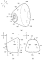
- FIG. 4 is a diagram illustrating the variant steering wheel 106 of FIG. 1A from each direction.
- FIG. 4A is an enlarged view of the variant steering wheel 106 of FIG.
- the cover 110 of the hub 108 is devised in order to consider the safety aspect when the cushion 104 (see FIG. 3) is inflated and deployed and to further improve the occupant restraint performance.
- the upper side of the hub 108 means the upper side of the straight line connecting 3 o'clock and 9 o'clock when the variant steering wheel 106 is regarded as a timepiece and the axis of the hand of the timepiece is at the center of the hub 108.
- the upper portion of the odd-shaped steering wheel 106 may be installed so as to be inclined toward the vehicle front side. Therefore, the vertical direction of variant steering wheel 106 is a direction connecting 12 o'clock and 6 o'clock when variant steering wheel 106 is regarded as a timepiece, and may not coincide with the actual vertical direction.
- the lateral direction of the odd-shaped steering wheel 106 is the direction of 3 o'clock or 9 o'clock when the odd-shaped steering wheel 106 is regarded as a timepiece.
- FIG. 4B is a cross-sectional view taken along the line AA of the hub 108 of the variant steering wheel 106 of FIG. 4A.
- the hub 108 includes a module housing portion 109 that houses the airbag module 105, and a cover 110 that covers the module housing portion 109.
- the cover 110 can be cleaved by the inflation pressure of the cushion 104. Therefore, a groove portion 160 that induces cleavage is carved on the surface of the cover 110 on the module housing portion 109 side.
- the cover 110 has a structure in which a plurality of cover doors 162a and 162b are formed when the cover 110 is torn, and the groove 160 defines the shape of the cover door 162a.
- the cover 110 has a configuration in which two cover doors 162a and 162b are formed.
- the cover doors 162a and 162b are formed by dividing the cover 110 into right and left parts such that the right cover door 162a includes the emblem 164.
- hinges 166a and 166b that connect the main body of the cover 110 and the cover doors 162a and 162b are formed on the cover 110 so that the cover door 162a does not scatter.
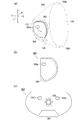
- FIG. 5 is a diagram exemplifying a state when the cover 110 of FIG. 4A is opened.
- FIG. 5 illustrates the vicinity of the hub 108 of the modified steering wheel 106 through the steering side panel 122 of the cushion 104.
- the two cover doors 162a and 162b are slanted in the left-right direction when viewed from the center P4 of the hub 108. Open towards each.
- the hinges 166a and 166b are formed as non-cleavable regions between the end points of the groove 160 at the respective positions diagonally upward and leftward from the center P4 of the hub 108.
- the hinges 166a and 166b have an area of an angle of 45° ⁇ 15° with respect to a horizontal line passing through the center P4 with respect to the center P4 of the hub 108, that is, an angle ⁇ 1 and an angle ⁇ 2 between 30° and 60°. Is provided in the area within the range.
- the hinges 166a and 166b having this configuration, when the variant steering wheel 106 is regarded as a timepiece, the left cover door 162a opens toward the range between 10 o'clock and 11 o'clock, and the right cover door 162b opens at 1 o'clock and 2 o'clock. Open towards the range between the letters.
- odd-shaped steering wheel 106 As represented by the odd-shaped steering wheel 106, many new steering wheels that have been developed in recent years are not circular as in the past. For example, there are various designs such that the rim exists only on the left and right sides of the hub, or the part of the rim above the hub approaches the hub side. When the cover door is opened in a direction directly above the hub 108, the odd-shaped steering wheel 106 having a shape other than the circular shape may not have a structure around the cover door that avoids contact between the cover door and an occupant.
- the rim is omitted or the rim becomes the hub in a range above the straight line connecting the 3 o'clock and 9 o'clock passing through the center of the hub 108.
- the design may be closer.
- the configuration in which the cover doors 162a and 162b are opened diagonally upward and leftward and rightward is realized. That is, the present embodiment does not include a cover door that opens in the directly upward direction (direction at 12:00) when viewed from the center P4 of the hub 108.
- the cover doors 162a and 162b are opened diagonally upward and to the left and right, when the upper half of the body of the occupant 138 (see FIG. 3) moves forward so as to fall forward in an emergency of the vehicle, as compared with the cover door opened directly above. It is possible to avoid contact with the occupant 138.
- the rim 114 does not exist on the upper side (12 o'clock side) of the hub 108 as compared with the conventional circular steering wheel, so that the occupant 138 (see FIG. 3) can easily lean forward in the vehicle. ..
- the head 140 of the occupant 138 may be located above the hub 108.
- the head of the occupant 138 is opened when the cover door is opened directly above. The possibility that the portion 140 and the cover door will come into contact with each other is further increased.
- the cover doors 162a and 162b open diagonally upward and to the left and right when the cover 110 is opened, and therefore, when viewed from the center P4 of the hub 108.
- a space S1 having no cover doors 162a and 162b is formed immediately above. That is, according to this embodiment, the cover doors 162a and 162b open to the left and right so as to form the space S1, so that the possibility of contact between the cover 110 and the head 140 can be reduced.
- cover doors 162a and 162b that open obliquely upward and to the left and right according to the present embodiment, it is possible to avoid contact with the rim 114 and switches existing on the left and right and below the hub 108. By reducing the chances that the cover doors 162a and 162b come into contact with a structure such as a rim, it is possible to prevent the cover doors 162a and 162b from falling off due to an impact, and it is possible to further enhance safety.
- the cover door 162a that opens diagonally upward and to the left and right with respect to the odd-shaped steering wheel 106 can be used as a support surface of the cushion 104.
- the cover 110 is configured to be split only by the groove 160 and move only by the hinges 166a and 166b, so that the cover doors 162a and 162b can have a predetermined rigidity.
- the cover doors 162a and 162b support the upper front side of the airbag cushion 104, so that the cushion 104 can cause the behavior toward the lower rear side.
- the cushion 104 is inflated and deployed toward the rear lower side, so that the cushion 104 is inserted between the variant steering wheel 106 and the abdomen 142 of the occupant 138, and the cushion 104 is expanded.
- the posture of the cushion 104 is less likely to be collapsed, and the restraint performance of the cushion 104 with respect to the head 140 of the occupant 138 can be improved. Further, if the behavior of the cushion 104 toward the lower rear side is lower than that of the behavior toward the upper rear side, the head 140 of the occupant 138 is less likely to come into contact with the head 140 from below. It is possible to prevent the movement of the head 140 that tends to increase the injury value. In particular, since the cushion 104 is likely to come into contact with the head 140 of the out-of-position occupant 138 from below, it is extremely effective to cause the cushion 104 to move backward and downward.
- the range E1 below the center P4 of the hub 108 in the groove may be deeper than the range E2 above the center P4 of the hub 108.
- the range E1 below the center P4 of the hub 108 in the groove is preferably thinner than the range E2 above the center P4 of the hub 108.
- the lower range E2 induces the cleavage earlier than the upper range E1 and the rate of the cleavage also becomes faster, and therefore the groove portions 160 are directed diagonally upward to the left and right toward the cover doors 162a and 162b. The movement can be efficiently generated.
- the vent holes 126a and 126b are provided on the left and right upper sides of the side panel 124.
- the vent holes 126a and 126b are preferably provided on the side panel 124 at positions diagonally above and to the left and right of the center P4 of the hub 108 (see FIG. 4A). With the vent holes 126a and 126b, it becomes possible to discharge the gas in the direction in which there is no occupant.
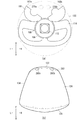
- FIG. 6 is a sectional view of the variant steering wheel 106 of FIG. 4A taken along the line BB.
- the cover 110 may have a shape in which the upper side is inclined toward the front of the vehicle as compared with the lower side.
- the cover 110 has a shape in which the occupant-side design surface is inclined at an angle ⁇ 3 toward the front of the vehicle with respect to the vertical line.
- the above-described cover doors 162a and 162b are connected to the hub 108.
- the cover door 162a can be utilized to support the upper front side of the cushion 104 and to inflate and deploy the cushion 104 toward the lower rear side by opening the cover door 162a diagonally upward.
- the driver-seat airbag device 100 capable of fully restraining the occupant 138 (see FIG. 3) while considering safety when inflating and deploying. You can
- FIG. 7 is a diagram illustrating a modified example of the internal structure of the cushion 104 of FIG. 2( a ).
- FIG. 7A exemplifies the internal structure of the cushion 104 of FIG. 2A through each panel.
- the cushion 104 is provided with a straightening cloth 360 as a new internal structure.
- the straightening cloth 360 is a member that guides the gas of the inflator 112 (see FIG. 2A) in a specific direction, and covers the portion of the inserted inflator 112 having the gas discharge port 116 inside. In the state, it is connected to the steering side panel 122.
- the straightening cloth 360 has an opening 364 for discharging gas below the inflator 112, and also has small-diameter exhaust ports 366a, 366b (see FIG. 7C) for discharging gas also on the side.
- FIG. 7B is a diagram illustrating the flow regulating cloth 360 of FIG. 7A from the side.
- the straightening cloth 360 is formed into a bag shape by sewing, and the lower edge is opened to form an opening 364.
- FIG. 7C illustrates a state in which the straightening cloth 360 of FIG. 7B is unsewn and spread on a plane.
- the rectifying cloth 360 is provided with an insertion port 368 in the center thereof through which a part of the inflator 112 (see FIG. 2A) is inserted, and the stud bolt 118 of the inflator 112 together with the steering side panel 122 and the hub 108 (FIG. 1). (See (a)).
- the exhaust ports 366a and 366b are provided at two positions on the left and right, and supply gas to the vicinity of the center of the cushion 104.
- the opening 364 is formed to have a larger diameter than the exhaust ports 366a and 366b, and has a larger gas passage amount than the exhaust ports 366a and 366b.
- the gas supplied from the inflator 112 is preferentially supplied to the lower portion 104b of the cushion 104 (FIG. 7A) through the opening 364 by the above-described straightening cloth 360.
- the cushion 104 preferentially expands and deploys from the lower portion 104b side.
- the cushion 104 allows the lower portion 104b to be early inserted between the variant steering wheel 106 (see FIG. 4) and the abdomen 142 of the occupant 138 so as to be sandwiched between the variant steering wheel 106 and the abdomen 142. It will be possible.
- FIG. 8 is a diagram illustrating each modified example of the vent hole in FIG. 2(c).
- FIG. 8A illustrates a first modification example (second vent holes 270a and 270b) of the vent hole of FIG. 2C.
- the vent holes 270a and 270b are provided in the steering side panel 122.
- the vent holes 270a and 270b are provided in the steering side panel 122 at positions where the odd-shaped steering wheel 106 and the cover door 162 do not overlap.
- the vent holes 270a and 270b also allow the gas to be discharged in the direction in which the occupant does not exist.
- FIG. 8B illustrates a second modification example (third vent holes 280a and 280b) of the vent holes 126a and 126b of FIG. 2C.
- the vent holes 280a and 280b are formed by opening a part of a boundary 282 between the side panel 124 and the steering side panel 122.
- the boundary between the side panel 124 and the steering side panel 122 is located on the front side of the vehicle, and the body of the occupant 138 (see FIG. 3) is not located around the boundary, especially on the upper side. Therefore, by opening a part of the upper side of the boundary 282 between the side panel 124 and the steering side panel 122 to form the vent holes 280a and 280b, it becomes possible to discharge the gas in the direction in which the occupant 138 does not exist.
- the above-described first vent holes 126a and 126b, the second vent holes 270a and 270b, and the third vent holes 280a and 280b can be simultaneously implemented for one airbag cushion.
- the airbag cushion can appropriately implement each of these vent holes depending on the positional relationship with the occupant and the arrangement of surrounding structures.
- the present invention can be applied to a driver airbag device that restrains an occupant in an emergency.
Landscapes
- Engineering & Computer Science (AREA)
- Mechanical Engineering (AREA)
- Air Bags (AREA)
Abstract
Description
以下、上述した各構成洋装の変形例について説明する。図7および図8では、既に説明した構成要素と同じものについては、同じ符号を付することによって説明を省略する。また、以下の説明では、既に説明した構成要素と同じ名称のものについては、例え異なる符号を付していても、特に明記しない場合は同じ機能を有するものとする。
Claims (11)
- 車両のステアリングホイールと、インフレータおよびエアバッグクッションを含み該ステアリングホイールに収容されるエアバッグモジュールとを備えた運転席用エアバッグ装置であって、
前記ステアリングホイールは、
中央のハブと、
前記乗員が把持するリムとを有し、
前記リムは、前記ハブの上方の範囲が一部省略された形状、または該ハブの上方に位置する部位が該ハブの左右に位置する部位に比べて該ハブ側に近づいた形状になっていて、
前記ハブは、
前記エアバッグモジュールを収容するモジュール収容部と、
前記モジュール収容部を覆い前記エアバッグクッションの膨張圧で開裂可能なカバーとを有し、
前記カバーは、前記エアバッグクッションの膨張圧を受けると開く複数のカバードアを含み、
前記カバーが開裂した状態において、前記複数のカバードアは前記ハブの中央から見て左右斜め上方向それぞれに向かって開いていて、該ハブの中央から見て直上方向には、該複数のカバードアの無い空間部が形成されていることを特徴とする運転席用エアバッグ装置。 - 前記複数のカバードアは少なくとも2枚あり、該2枚のカバードアは前記カバーを左右に二分していることを特徴とする請求項1に記載の運転席用エアバッグ装置。
- 前記カバーは、
前記エアバッグクッションの膨張圧によって開裂可能で前記複数のカバードアの形状を規定する溝部と、
前記ハブの中央から左右斜め上方向に離れたそれぞれの箇所に形成される前記溝部の端点同士の間の開裂しないヒンジと、を有することを特徴とする請求項1または2に記載の運転席用エアバッグ装置。 - 前記ヒンジは、前記ハブの中央を原点として当該中央を通る水平線に対して45°±15°の角度の領域に設けられていることを特徴とする請求項3に記載の運転席用エアバッグ装置。
- 前記溝部のうち前記ハブの中央の下側の範囲は、該ハブの中央の上側の範囲よりも深く彫られていることを特徴とする請求項3または4に記載の運転席用エアバッグ装置。
- 前記溝部のうち前記ハブの中央の下側の範囲は、該ハブの中央の上側の範囲よりも薄肉であることを特徴とする請求項3または4に記載の運転席用エアバッグ装置。
- 前記カバーは、上側が下側に比べて車両前方に傾いた形状になっていることを特徴とする請求項1から6のいずれか1項に記載の運転席用エアバッグ装置。
- 前記インフレータの一部は、前記エアバッグクッション内に挿入されていて、該一部には所定のガス排出口が形成されていて、
当該運転席用エアバッグ装置はさらに、前記エアバッグクッション内に設置されていて前記インフレータの一部を覆う整流布を備え、
前記整流布は、前記インフレータの一部の下方に開口部を有していることを特徴とする請求項1から7のいずれか1項に記載の運転席用エアバッグ装置。 - 前記エアバッグクッションは、
前記ステアリングホイール側に位置するステアリング側パネルと、
前記乗員側に位置する乗員側パネルと、
前記ステアリング側パネルの縁と前記乗員側パネルの縁とをつないでいて該エアバッグクッションの側部を構成するサイドパネルと、
前記サイドパネルのうち前記ハブの中央に対する左右斜め上方それぞれの箇所に設けられてガスを排出する第1のベントホールとを含むことを特徴とする請求項1から8のいずれか1項に記載の運転席用エアバッグ装置。 - 前記エアバッグクッションは、
前記ステアリングホイール側に位置するステアリング側パネルと、
前記乗員側に位置する乗員側パネルと、
前記ステアリング側パネルの縁と前記乗員側パネルの縁とをつないでいて該エアバッグクッションの側部を構成するサイドパネルと、
前記ステアリング側パネルのうち前記ステアリングホイールおよび前記複数のカバードアの重ならない箇所に設けられてガスを排出する第2のベントホールとを含むことを特徴とする請求項1から8のいずれか1項に記載の運転席用エアバッグ装置。 - 前記エアバッグクッションは、
前記ステアリングホイール側に位置するステアリング側パネルと、
前記乗員側に位置する乗員側パネルと、
前記ステアリング側パネルの縁と前記乗員側パネルの縁とをつないでいて該エアバッグクッションの側部を構成するサイドパネルと、
前記サイドパネルと前記ステアリング側パネルとの境界のうち前記ハブの中央に対する左右斜め上方それぞれの箇所を開放した状態になっていてガスを排出する第3のベントホールを含むことを特徴とする請求項1から8のいずれか1項に記載の運転席用エアバッグ装置。
Priority Applications (5)
| Application Number | Priority Date | Filing Date | Title |
|---|---|---|---|
| CN202080010142.XA CN113329916B (zh) | 2019-02-19 | 2020-02-07 | 驾驶座用安全气囊装置 |
| JP2021501864A JP7142141B2 (ja) | 2019-02-19 | 2020-02-07 | 運転席用エアバッグ装置 |
| EP20758563.9A EP3929039B1 (en) | 2019-02-19 | 2020-02-07 | Airbag device for driver's seat |
| US17/310,632 US12024111B2 (en) | 2019-02-19 | 2020-02-07 | Airbag device for driver's seat |
| KR1020217029391A KR102585272B1 (ko) | 2019-02-19 | 2020-02-07 | 운전석용 에어백 장치 |
Applications Claiming Priority (2)
| Application Number | Priority Date | Filing Date | Title |
|---|---|---|---|
| JP2019-027905 | 2019-02-19 | ||
| JP2019027905 | 2019-02-19 |
Publications (1)
| Publication Number | Publication Date |
|---|---|
| WO2020170864A1 true WO2020170864A1 (ja) | 2020-08-27 |
Family
ID=72143661
Family Applications (1)
| Application Number | Title | Priority Date | Filing Date |
|---|---|---|---|
| PCT/JP2020/004892 Ceased WO2020170864A1 (ja) | 2019-02-19 | 2020-02-07 | 運転席用エアバッグ装置 |
Country Status (6)
| Country | Link |
|---|---|
| US (1) | US12024111B2 (ja) |
| EP (1) | EP3929039B1 (ja) |
| JP (1) | JP7142141B2 (ja) |
| KR (1) | KR102585272B1 (ja) |
| CN (1) | CN113329916B (ja) |
| WO (1) | WO2020170864A1 (ja) |
Cited By (1)
| Publication number | Priority date | Publication date | Assignee | Title |
|---|---|---|---|---|
| JPWO2022118550A1 (ja) * | 2020-12-03 | 2022-06-09 |
Families Citing this family (4)
| Publication number | Priority date | Publication date | Assignee | Title |
|---|---|---|---|---|
| EP3988400B1 (en) * | 2019-06-18 | 2025-11-26 | Autoliv Development AB | Driver's seat airbag device |
| DE202019103552U1 (de) * | 2019-06-27 | 2020-10-08 | ZF Automotive Safety Germany GmbH | Fahrergassackmodul sowie Lenkvorrichtung mit einem solchen Fahrergassackmodul |
| WO2021111746A1 (ja) * | 2019-12-05 | 2021-06-10 | オートリブ ディベロップメント エービー | エアバッグ装置 |
| DE102020102866A1 (de) * | 2020-02-05 | 2021-08-05 | Zf Automotive Germany Gmbh | Fahrzeuginsassen-Rückhaltesystem mit Frontgassack und Seitengassack |
Citations (10)
| Publication number | Priority date | Publication date | Assignee | Title |
|---|---|---|---|---|
| JPH06312641A (ja) * | 1993-04-30 | 1994-11-08 | Tokai Rika Co Ltd | エアバッグ用カバー |
| US5730460A (en) * | 1996-11-22 | 1998-03-24 | General Motors Corporation | Air bag cover |
| JP2000038107A (ja) * | 1998-07-22 | 2000-02-08 | Nippon Plast Co Ltd | 自動車用ステアリングホイール |
| JP2006076381A (ja) * | 2004-09-08 | 2006-03-23 | Mazda Motor Corp | エアバッグ装置を備えたステアリングホイール |
| JP2007076619A (ja) * | 2005-09-16 | 2007-03-29 | Toyota Motor Corp | 運転席用エアバッグ装置 |
| JP3991739B2 (ja) | 2002-03-26 | 2007-10-17 | タカタ株式会社 | エアバッグ、エアバッグ装置及びステアリング |
| JP2008105521A (ja) * | 2006-10-25 | 2008-05-08 | Toyota Motor Corp | ステアリング操作装置 |
| JP2008173994A (ja) * | 2007-01-16 | 2008-07-31 | Toyota Motor Corp | 車両のエアバック装置 |
| JP2012071687A (ja) * | 2010-09-29 | 2012-04-12 | Fuji Heavy Ind Ltd | 車両用表示装置 |
| JP2019006306A (ja) * | 2017-06-27 | 2019-01-17 | Joyson Safety Systems Japan株式会社 | ステアリング装置 |
Family Cites Families (11)
| Publication number | Priority date | Publication date | Assignee | Title |
|---|---|---|---|---|
| JP4129758B2 (ja) * | 1998-08-10 | 2008-08-06 | 俊毅 内田 | エアバッグ装置 |
| KR100510359B1 (ko) * | 2003-03-10 | 2005-08-24 | 현대모비스 주식회사 | 자동차용 운전석 에어백 |
| US7445238B2 (en) * | 2005-05-06 | 2008-11-04 | Tk Holdings Inc. | Occupant protection apparatus |
| JP2008037141A (ja) * | 2006-08-01 | 2008-02-21 | Takata Corp | エアバッグカバー、インストルメントパネル、エアバッグ装置 |
| JP4241799B2 (ja) * | 2006-10-16 | 2009-03-18 | トヨタ自動車株式会社 | 車両用ステアリング装置 |
| DE102007013469B4 (de) * | 2007-03-21 | 2012-05-31 | Autoliv Development Ab | Abdeckelement für ein Gassackmodul |
| JP5962602B2 (ja) * | 2013-07-03 | 2016-08-03 | トヨタ自動車株式会社 | 前席エアバッグシステム |
| DE102013011579A1 (de) * | 2013-07-11 | 2015-01-15 | Audi Ag | Fahrzeuglenkrad mit einer Airbageinheit |
| US9505369B2 (en) * | 2014-09-12 | 2016-11-29 | Toyoda Gosei Co., Ltd. | Side airbag apparatus |
| JP2018020737A (ja) * | 2016-08-05 | 2018-02-08 | タカタ株式会社 | 運転席用エアバッグ、運転席用エアバッグ装置及びステアリングホイール |
| US10144383B2 (en) * | 2016-09-29 | 2018-12-04 | Steering Solutions Ip Holding Corporation | Steering wheel with video screen and airbag |
-
2020
- 2020-02-07 US US17/310,632 patent/US12024111B2/en active Active
- 2020-02-07 CN CN202080010142.XA patent/CN113329916B/zh active Active
- 2020-02-07 JP JP2021501864A patent/JP7142141B2/ja active Active
- 2020-02-07 KR KR1020217029391A patent/KR102585272B1/ko active Active
- 2020-02-07 EP EP20758563.9A patent/EP3929039B1/en active Active
- 2020-02-07 WO PCT/JP2020/004892 patent/WO2020170864A1/ja not_active Ceased
Patent Citations (10)
| Publication number | Priority date | Publication date | Assignee | Title |
|---|---|---|---|---|
| JPH06312641A (ja) * | 1993-04-30 | 1994-11-08 | Tokai Rika Co Ltd | エアバッグ用カバー |
| US5730460A (en) * | 1996-11-22 | 1998-03-24 | General Motors Corporation | Air bag cover |
| JP2000038107A (ja) * | 1998-07-22 | 2000-02-08 | Nippon Plast Co Ltd | 自動車用ステアリングホイール |
| JP3991739B2 (ja) | 2002-03-26 | 2007-10-17 | タカタ株式会社 | エアバッグ、エアバッグ装置及びステアリング |
| JP2006076381A (ja) * | 2004-09-08 | 2006-03-23 | Mazda Motor Corp | エアバッグ装置を備えたステアリングホイール |
| JP2007076619A (ja) * | 2005-09-16 | 2007-03-29 | Toyota Motor Corp | 運転席用エアバッグ装置 |
| JP2008105521A (ja) * | 2006-10-25 | 2008-05-08 | Toyota Motor Corp | ステアリング操作装置 |
| JP2008173994A (ja) * | 2007-01-16 | 2008-07-31 | Toyota Motor Corp | 車両のエアバック装置 |
| JP2012071687A (ja) * | 2010-09-29 | 2012-04-12 | Fuji Heavy Ind Ltd | 車両用表示装置 |
| JP2019006306A (ja) * | 2017-06-27 | 2019-01-17 | Joyson Safety Systems Japan株式会社 | ステアリング装置 |
Non-Patent Citations (1)
| Title |
|---|
| See also references of EP3929039A4 |
Cited By (4)
| Publication number | Priority date | Publication date | Assignee | Title |
|---|---|---|---|---|
| JPWO2022118550A1 (ja) * | 2020-12-03 | 2022-06-09 | ||
| WO2022118550A1 (ja) * | 2020-12-03 | 2022-06-09 | オートリブ ディベロップメント エービー | エアバッグ装置 |
| JP7514951B2 (ja) | 2020-12-03 | 2024-07-11 | オートリブ ディベロップメント エービー | エアバッグ装置 |
| US12202424B2 (en) | 2020-12-03 | 2025-01-21 | Autoliv Development Ab | Airbag device |
Also Published As
| Publication number | Publication date |
|---|---|
| JP7142141B2 (ja) | 2022-09-26 |
| US12024111B2 (en) | 2024-07-02 |
| KR102585272B1 (ko) | 2023-10-05 |
| JPWO2020170864A1 (ja) | 2021-10-14 |
| CN113329916B (zh) | 2023-08-15 |
| KR20210125080A (ko) | 2021-10-15 |
| EP3929039A4 (en) | 2022-12-14 |
| EP3929039B1 (en) | 2025-01-15 |
| US20220144201A1 (en) | 2022-05-12 |
| CN113329916A (zh) | 2021-08-31 |
| EP3929039A1 (en) | 2021-12-29 |
Similar Documents
| Publication | Publication Date | Title |
|---|---|---|
| JP7142141B2 (ja) | 運転席用エアバッグ装置 | |
| JP7148647B2 (ja) | 運転席エアバッグ | |
| JP7316364B2 (ja) | 運転席用エアバッグ装置 | |
| JP7449930B2 (ja) | サイドエアバッグ装置及び、サイドエアバッグ装置の製造方法 | |
| JPWO2016013279A1 (ja) | サイドエアバッグ装置 | |
| JP2018024285A (ja) | エアバッグ装置 | |
| JP2019085047A (ja) | 後席サイドエアバッグ装置 | |
| WO2018211894A1 (ja) | サイドエアバッグ装置 | |
| JP7212160B2 (ja) | 運転席用エアバッグ装置 | |
| JP2008509042A (ja) | 側面エアバッグ装置 | |
| JP2008509042A5 (ja) | ||
| JP7508638B2 (ja) | 運転席用エアバッグ装置 | |
| JP3991720B2 (ja) | 乗員保護装置 | |
| JP7808704B2 (ja) | 乗員保護装置 | |
| WO2023145244A1 (ja) | 運転席用エアバッグ装置 | |
| JP6762240B2 (ja) | エアバッグ | |
| JP7412582B2 (ja) | 運転席用エアバッグ装置 | |
| KR20040025166A (ko) | 헤드레스트의 에어백시스템 | |
| WO2024116628A1 (ja) | 運転席用エアバッグ | |
| KR100305926B1 (ko) | 자동차의 사이드 에어백 쿠션 | |
| WO2025225489A1 (ja) | 車両用エアバッグ装置 | |
| CN118574753A (zh) | 驾驶座用安全气囊装置 |
Legal Events
| Date | Code | Title | Description |
|---|---|---|---|
| 121 | Ep: the epo has been informed by wipo that ep was designated in this application |
Ref document number: 20758563 Country of ref document: EP Kind code of ref document: A1 |
|
| ENP | Entry into the national phase |
Ref document number: 2021501864 Country of ref document: JP Kind code of ref document: A |
|
| NENP | Non-entry into the national phase |
Ref country code: DE |
|
| ENP | Entry into the national phase |
Ref document number: 20217029391 Country of ref document: KR Kind code of ref document: A |
|
| ENP | Entry into the national phase |
Ref document number: 2020758563 Country of ref document: EP Effective date: 20210920 |