WO2020171112A1 - アルカリ二次電池 - Google Patents
アルカリ二次電池 Download PDFInfo
- Publication number
- WO2020171112A1 WO2020171112A1 PCT/JP2020/006462 JP2020006462W WO2020171112A1 WO 2020171112 A1 WO2020171112 A1 WO 2020171112A1 JP 2020006462 W JP2020006462 W JP 2020006462W WO 2020171112 A1 WO2020171112 A1 WO 2020171112A1
- Authority
- WO
- WIPO (PCT)
- Prior art keywords
- positive electrode
- oxygen
- electrode lead
- secondary battery
- lid plate
- Prior art date
- Legal status (The legal status is an assumption and is not a legal conclusion. Google has not performed a legal analysis and makes no representation as to the accuracy of the status listed.)
- Ceased
Links
Images


Classifications
-
- H—ELECTRICITY
- H01—ELECTRIC ELEMENTS
- H01M—PROCESSES OR MEANS, e.g. BATTERIES, FOR THE DIRECT CONVERSION OF CHEMICAL ENERGY INTO ELECTRICAL ENERGY
- H01M10/00—Secondary cells; Manufacture thereof
- H01M10/24—Alkaline accumulators
- H01M10/28—Construction or manufacture
-
- H—ELECTRICITY
- H01—ELECTRIC ELEMENTS
- H01M—PROCESSES OR MEANS, e.g. BATTERIES, FOR THE DIRECT CONVERSION OF CHEMICAL ENERGY INTO ELECTRICAL ENERGY
- H01M4/00—Electrodes
- H01M4/02—Electrodes composed of, or comprising, active material
- H01M4/24—Electrodes for alkaline accumulators
- H01M4/242—Hydrogen storage electrodes
-
- H—ELECTRICITY
- H01—ELECTRIC ELEMENTS
- H01M—PROCESSES OR MEANS, e.g. BATTERIES, FOR THE DIRECT CONVERSION OF CHEMICAL ENERGY INTO ELECTRICAL ENERGY
- H01M50/00—Constructional details or processes of manufacture of the non-active parts of electrochemical cells other than fuel cells, e.g. hybrid cells
- H01M50/10—Primary casings; Jackets or wrappings
- H01M50/102—Primary casings; Jackets or wrappings characterised by their shape or physical structure
- H01M50/107—Primary casings; Jackets or wrappings characterised by their shape or physical structure having curved cross-section, e.g. round or elliptic
-
- H—ELECTRICITY
- H01—ELECTRIC ELEMENTS
- H01M—PROCESSES OR MEANS, e.g. BATTERIES, FOR THE DIRECT CONVERSION OF CHEMICAL ENERGY INTO ELECTRICAL ENERGY
- H01M50/00—Constructional details or processes of manufacture of the non-active parts of electrochemical cells other than fuel cells, e.g. hybrid cells
- H01M50/10—Primary casings; Jackets or wrappings
- H01M50/147—Lids or covers
-
- H—ELECTRICITY
- H01—ELECTRIC ELEMENTS
- H01M—PROCESSES OR MEANS, e.g. BATTERIES, FOR THE DIRECT CONVERSION OF CHEMICAL ENERGY INTO ELECTRICAL ENERGY
- H01M50/00—Constructional details or processes of manufacture of the non-active parts of electrochemical cells other than fuel cells, e.g. hybrid cells
- H01M50/10—Primary casings; Jackets or wrappings
- H01M50/183—Sealing members
-
- H—ELECTRICITY
- H01—ELECTRIC ELEMENTS
- H01M—PROCESSES OR MEANS, e.g. BATTERIES, FOR THE DIRECT CONVERSION OF CHEMICAL ENERGY INTO ELECTRICAL ENERGY
- H01M50/00—Constructional details or processes of manufacture of the non-active parts of electrochemical cells other than fuel cells, e.g. hybrid cells
- H01M50/50—Current conducting connections for cells or batteries
- H01M50/531—Electrode connections inside a battery casing
- H01M50/533—Electrode connections inside a battery casing characterised by the shape of the leads or tabs
-
- H—ELECTRICITY
- H01—ELECTRIC ELEMENTS
- H01M—PROCESSES OR MEANS, e.g. BATTERIES, FOR THE DIRECT CONVERSION OF CHEMICAL ENERGY INTO ELECTRICAL ENERGY
- H01M50/00—Constructional details or processes of manufacture of the non-active parts of electrochemical cells other than fuel cells, e.g. hybrid cells
- H01M50/50—Current conducting connections for cells or batteries
- H01M50/531—Electrode connections inside a battery casing
- H01M50/534—Electrode connections inside a battery casing characterised by the material of the leads or tabs
-
- H—ELECTRICITY
- H01—ELECTRIC ELEMENTS
- H01M—PROCESSES OR MEANS, e.g. BATTERIES, FOR THE DIRECT CONVERSION OF CHEMICAL ENERGY INTO ELECTRICAL ENERGY
- H01M2300/00—Electrolytes
- H01M2300/0002—Aqueous electrolytes
- H01M2300/0014—Alkaline electrolytes
-
- Y—GENERAL TAGGING OF NEW TECHNOLOGICAL DEVELOPMENTS; GENERAL TAGGING OF CROSS-SECTIONAL TECHNOLOGIES SPANNING OVER SEVERAL SECTIONS OF THE IPC; TECHNICAL SUBJECTS COVERED BY FORMER USPC CROSS-REFERENCE ART COLLECTIONS [XRACs] AND DIGESTS
- Y02—TECHNOLOGIES OR APPLICATIONS FOR MITIGATION OR ADAPTATION AGAINST CLIMATE CHANGE
- Y02E—REDUCTION OF GREENHOUSE GAS [GHG] EMISSIONS, RELATED TO ENERGY GENERATION, TRANSMISSION OR DISTRIBUTION
- Y02E60/00—Enabling technologies; Technologies with a potential or indirect contribution to GHG emissions mitigation
- Y02E60/10—Energy storage using batteries
-
- Y—GENERAL TAGGING OF NEW TECHNOLOGICAL DEVELOPMENTS; GENERAL TAGGING OF CROSS-SECTIONAL TECHNOLOGIES SPANNING OVER SEVERAL SECTIONS OF THE IPC; TECHNICAL SUBJECTS COVERED BY FORMER USPC CROSS-REFERENCE ART COLLECTIONS [XRACs] AND DIGESTS
- Y02—TECHNOLOGIES OR APPLICATIONS FOR MITIGATION OR ADAPTATION AGAINST CLIMATE CHANGE
- Y02P—CLIMATE CHANGE MITIGATION TECHNOLOGIES IN THE PRODUCTION OR PROCESSING OF GOODS
- Y02P70/00—Climate change mitigation technologies in the production process for final industrial or consumer products
- Y02P70/50—Manufacturing or production processes characterised by the final manufactured product
Definitions
- the above-mentioned sealing body is a lid plate fitted into the opening of the outer can, and a lid plate having a vent hole in the center, and a valve body arranged so as to close the vent hole,
- the positive electrode cap which accommodates this valve body and is welded to the cover plate is provided.
- This positive electrode cap has a tubular body portion, a top wall that closes one end of the body portion, and a flange that is provided on the peripheral edge of the opening on the side opposite to the top wall, and also functions as a positive electrode terminal. ing.
- a gas vent hole is provided on the side surface of the body portion.
- the ambient temperature may rise and oxygen gas may easily be generated from the positive electrode. If the amount of oxygen gas generated from the positive electrode exceeds the amount of oxygen gas absorbed by the negative electrode, the outer can of the nickel-hydrogen secondary battery may burst. In order to avoid such a situation, the nickel-hydrogen secondary battery is provided with the above-mentioned safety valve.
- Patent Document 1 discloses a method of adding a noble metal catalyst such as platinum to the negative electrode to accelerate the reduction of oxygen gas
- Patent Document 2 provides a hydrogen-absorbing alloy negative electrode with a water-repellent layer to form oxygen gas. There is disclosed a technique for accelerating the absorption on the negative electrode.
- nickel-hydrogen secondary batteries are expanding more and more recently, and they are used, for example, as a backup power source for the purpose of measures against power failure in an emergency.
- the backup power supply is equipped in case of sudden and short interruption of power supply such as power failure, so the continuous charging method that always charges is adopted. In the case of continuous charging, overcharging tends to occur because the battery will continue to be charged even when it reaches full charge. Since oxygen gas is generated from the positive electrode when overcharged as described above, oxygen gas is generated from the positive electrode most of the time in applications that employ continuous charging.
- the reaction heat or Joule heat is generated by the battery reaction and the temperature rises, so the internal hydrogen storage alloy is exposed to high temperatures.
- the hydrogen storage alloy deteriorates when exposed to high temperatures.
- the period of exposure to high temperature is long, the deterioration of the hydrogen storage alloy progresses more than in the normal usage mode.
- the negative electrode can sufficiently absorb the oxygen gas.
- the ability of the hydrogen storage alloy itself to absorb the oxygen gas decreases, so that the measures for promoting the absorption of the oxygen gas as in Patent Documents 1 and 2 are taken. Even if it is applied, the absorption of oxygen gas becomes difficult to proceed. Therefore, oxygen gas increases in the battery as the period of continuous charging increases. Then, the constituent members in the battery are more exposed to the oxygen gas.
- the metallic parts including the lid plate and positive electrode lead, are made of iron-based materials plated with nickel. According to a normal charging method, the degree of exposure to oxygen gas is small, and thus the lid plate and the positive electrode lead can withstand oxidation sufficiently. However, in the case of continuous charging, since the degree of exposure to oxygen gas increases as described above, the lid plate and the positive electrode lead are oxidized and rust occurs. Particularly, the welded portion between the lid plate and the positive electrode lead and its periphery may have a thin nickel plating layer due to the influence of welding, and are easily rusted. Thus, if the welded portion between the lid plate and the positive electrode lead is rusted, the internal resistance value of the battery rises, and the battery may be unable to discharge.
- the present invention has been made based on the above circumstances, and an object thereof is to suppress the occurrence of rust in the metal parts inside the battery and the leakage of the alkaline electrolyte even when performing continuous charging. It is to provide an alkaline secondary battery that can be.
- an electrode group including a positive electrode and a negative electrode facing each other through a separator, and an outer can having an opening at the upper end, wherein the electrode group is an electrolytic solution.
- an outer can that is housed together with the lid, and a lid that is fitted into the opening of the outer can, and a sealing body that includes a positive electrode terminal that is electrically connected to an outer surface of the lid located outside the outer can.
- a positive electrode lead having one end electrically connected to an inner surface of the lid plate located inside the outer can and the other end electrically connected to the positive electrode; and the positive electrode.
- a coating layer that covers at least a range in which the one end of the lead and the inner surface of the lid plate overlap with each other, and a coating layer that suppresses permeation of oxygen, and the thickness of the thinnest portion in the coating layer.
- An alkaline secondary battery having a size of 3 ⁇ m or more is provided.
- the coating layer covers the entire surface of the positive electrode lead except for the surface where the positive electrode lead is in contact with another member.
- the coating layer is a range of the inner surface of the lid plate excluding a surface where the lid plate is in contact with another member, and the entire positive electrode lead has the positive electrode lead as another member. It is preferable to cover the area excluding the contacting surface.
- the alkaline secondary battery according to the present invention is an outer can having an electrode group including a positive electrode and a negative electrode facing each other through a separator, and an opening at an upper end, and the electrode group is accommodated together with an electrolytic solution.
- a coating layer that covers at least a range where the end portion and the inner surface of the lid plate overlap, and a coating layer that suppresses oxygen permeation, and the thinnest portion of the coating layer has a thickness of 3 ⁇ m or more. Is. This makes it possible to suppress oxidation of metal parts such as the lid plate and the positive electrode lead even if the exterior can is filled with oxygen gas due to continuous charging. Therefore, according to the present invention, it is possible to provide an alkaline secondary battery capable of suppressing the generation of rust on the metal components inside the battery and suppressing the leakage of the alkaline electrolyte even when continuously charged. ..
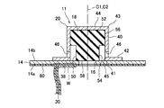
- FIG. 1 is a perspective view showing a cylindrical nickel-hydrogen secondary battery according to an embodiment of the present invention partially broken away. It is sectional drawing which expanded and showed the part of the sealing body of the nickel-hydrogen secondary battery which concerns on embodiment of this invention. It is sectional drawing which showed roughly the shape of the oxygen block layer which concerns on embodiment of this invention.
- the electrode group 22 is formed of a strip-shaped positive electrode 24, a negative electrode 26, and a separator 28, respectively. Specifically, the electrode group 22 is formed by spirally winding a positive electrode 24 and a negative electrode 26 that are stacked with a separator 28 interposed therebetween. The outermost periphery of the electrode group 22 is formed by a part of the negative electrode 26 (outermost periphery) and is in contact with the inner peripheral wall of the outer can 10. That is, the negative electrode 26 and the outer can 10 are electrically connected to each other.
- alkaline electrolyte (not shown) is injected into the outer can 10.
- This alkaline electrolyte advances the charge/discharge reaction between the positive electrode 24 and the negative electrode 26.
- this alkaline electrolyte one used in a general nickel-hydrogen secondary battery is used.
- the positive electrode additive is appropriately selected as necessary to improve the characteristics of the positive electrode.
- Examples of the main positive electrode additive include yttrium oxide and zinc oxide.
- the positive electrode 24 can be manufactured as follows, for example. First, a positive electrode mixture slurry containing a positive electrode active material powder, which is an aggregate of positive electrode active material particles, a conductive material, a positive electrode additive, water, and a binder is prepared. The obtained positive electrode mixture slurry is filled in, for example, nickel foam and dried. After drying, the foamed nickel filled with nickel hydroxide particles and the like is rolled and then cut. As a result, the positive electrode 24 holding the positive electrode mixture is manufactured.
- a positive electrode active material powder which is an aggregate of positive electrode active material particles, a conductive material, a positive electrode additive, water, and a binder is prepared.
- the obtained positive electrode mixture slurry is filled in, for example, nickel foam and dried. After drying, the foamed nickel filled with nickel hydroxide particles and the like is rolled and then cut. As a result, the positive electrode 24 holding the positive electrode mixture is manufactured.
- the negative electrode mixture contains particles of a hydrogen storage alloy, a negative electrode additive, a conductive material and a binder.
- the hydrogen storage alloy is an alloy capable of storing and releasing hydrogen, which is a negative electrode active material.
- the kind of the hydrogen storage alloy is not particularly limited, but a rare earth-Mg-Ni system hydrogen storage alloy containing a rare earth element, Mg and Ni is preferably used.
- the above-mentioned binder functions to bind the particles of the hydrogen storage alloy, the negative electrode additive and the conductive material to each other and at the same time bind the negative electrode mixture to the negative electrode core.
- a hydrophilic or hydrophobic polymer can be used as the binder, and carbon black, graphite, nickel powder or the like can be used as the conductive material.
- the negative electrode additive is appropriately selected as necessary to improve the characteristics of the negative electrode.
- the negative electrode 26 can be manufactured, for example, as follows. First, a hydrogen storage alloy powder, a conductive material, a binder, and water are prepared, and these are kneaded to prepare a negative electrode mixture paste. In addition, you may add a negative electrode additive further as needed. The obtained negative electrode mixture paste is applied to the negative electrode core body and dried. After drying, the negative electrode core to which the hydrogen storage alloy particles and the like are attached is rolled to increase the packing density of the hydrogen storage alloy, and then cut into a predetermined shape, whereby the negative electrode 26 is manufactured.
- the positive electrode 24 and the negative electrode 26 manufactured as described above are spirally wound with the separator 28 interposed, and thus the electrode group 22 is formed.
- the cover plate 14 is a disk-shaped member having conductivity, which is manufactured by processing a plate material made of nickel-plated steel, and is an inner surface 14a located inside the battery 2 and an opposite side to the inner surface 14a.
- the outer surface 14 b is located outside the battery 2.
- a central through hole 16 is provided in the center of the cover plate 14 as a ventilation hole penetrating from the inner surface 14a to the outer surface 14b.
- the central through hole 16 is normally closed by a valve body 18 described later.
- a lid plate 14 and a ring-shaped insulating packing 12 surrounding the lid plate 14 are arranged in the opening of the outer can 10, and the lid plate 14 and the insulating packing 12 are formed by caulking an opening edge 37 of the outer can 10. It is fixed to the opening edge 37 of the outer can 10.
- valve element 18 a valve element used in a general nickel-hydrogen secondary battery is used.
- a columnar or stepped columnar valve body made of a rubber material is used.
- the valve body 18 made of a rubber material is elastically deformable and is housed in the positive electrode cap 20 in a compressed state to some extent.
- the head portion 52 of the valve body 18 abuts on the inner surface of the top wall 44 of the positive electrode cap 20, and the valve body 18 is entirely pressed toward the lid plate 14.
- the base end surface 58 of the main body 54 of the valve body 18 covers the central through hole 16 and hermetically closes it. That is, the valve body 18 closes the central through hole 16 with a predetermined pressure.
- the oxygen blocking layer 60 as a coating layer for suppressing the permeation of oxygen is provided at predetermined positions on the inner surface 14a of the lid plate 14 and the surface of the positive electrode lead 30.
- the oxygen block layer 60 is formed of a material that can prevent the permeation of oxygen.
- a sealing agent used for maintaining airtightness is preferable. Further, since this sealing agent may come into contact with the alkaline electrolyte, it is more preferable that the sealing agent does not deteriorate in an alkaline atmosphere.
- a sealant include blown asphalt. This blown asphalt is used by dissolving it in an organic solvent (for example, toluene) to form a paste.
- the same effect can be obtained by using a rubber material.
- preferable rubber-based materials include rubber-based materials having alkali resistance, and specific examples thereof include ethylene propylene diene rubber.
- a material containing an additive such as chlorine or sulfur may promote the generation of rust in the metal material, so that a material containing chlorine or sulfur as an additive should be avoided.
- the material for forming the oxygen block layer 60 is not limited to the above-mentioned sealing agent, and is not particularly limited as long as it is an alkali-resistant material capable of coating the metal portion.
- the range in which the oxygen block layer 60 is formed is preferably a range that can cover a portion that is easily oxidized by oxygen gas.
- the portions of the cover plate 14 and the positive electrode lead 30 that are likely to be oxidized are the portions where the nickel plating layer is degenerated, thinned, or peeled off. Such a portion is mostly generated by the influence of welding work. That is, the welded portion W where the cover plate 14 and the positive electrode lead 30 are overlapped with each other is likely to be a portion where the nickel plating layer is denatured, thinned, or peeled off. Therefore, the oxygen block layer 60 is formed at least in the range where the positive electrode lead 30 overlaps the cover plate 14 and covers the welded portion W that is welded.
- the central through hole 16 is provided in the cover plate 14, but it is preferable to provide the oxygen blocking layer 60 also on the inner peripheral surface of the central through hole 16.
- the oxygen blocking layer 60 By providing the oxygen blocking layer 60 on the inner peripheral surface of the central through hole 16, it is possible to suppress the generation of rust with the inner peripheral surface of the central through hole 16 as a base point, which is more preferable.
- the thickness of the oxygen block layer 60 is less than 3 ⁇ m, it is not possible to sufficiently prevent the permeation of oxygen, and it is not possible to suppress the generation of rust.
- the thickness of the oxygen block layer 60 is set to 9 ⁇ m or more. This is because it is possible to more reliably prevent the permeation of oxygen and suppress the generation of rust.
- a thicker oxygen blocking layer 60 is preferable because it can block the permeation of oxygen.
- the thickness of the oxygen block layer 60 is preferably 9 ⁇ m or more and 80 ⁇ m or less, and more preferably 9 ⁇ m or more and 16 ⁇ m or less.
- Example 1 Production of nickel-hydrogen secondary battery (Example 1) (1) Manufacturing of Sealing Body First, a valve body 18 made of ethylene propylene diene rubber, which is generally used for nickel-hydrogen secondary batteries, was prepared. As shown in FIG. 2, the valve body 18 includes a cylindrical head portion 52 and a main body portion 54 having a diameter smaller than that of the head portion 52. The central axis C1 of the head portion 52 and the central axis C2 of the main body portion 54 coincide with each other. That is, the head portion 52 and the main body portion 54 are coaxial with each other. Therefore, the valve body 18 has a stepped cylindrical shape as a whole.
- the positive electrode cap 20 includes a cylindrical body portion 40, an annular flange 42 provided at the periphery of the opening 45 of the base end 41 of the body portion 40, and a base end 41.
- a gas vent hole 46 that opens to the side is formed in the lower portion of the body portion 40.
- the radius of the flange 42 was 4.9 mm.
- the inner surface 14a of the lid plate 14 of the sealing body 11 and the one end 38 of the positive electrode lead 30 were overlapped and welded.
- the positive electrode 24 and the positive electrode terminal (positive electrode cap 20) were electrically connected via the cover plate 14 and the positive electrode lead 30.
- the sealing agent is applied to a region of the inner surface 14a of the lid plate 14 excluding the surface where the lid plate 14 and the one end 38 of the positive electrode lead 30 are in contact with each other.
- the sealant was applied to a region excluding the surface where the one end portion 38 of 30 and the cover plate 14 are in contact with each other and the surface where the positive electrode lead 30 and the positive electrode 24 are in contact with each other to form the oxygen block layer 60. That is, the oxygen block layer 60 is formed over substantially the entire surface of the positive electrode lead 30 and the entire inner surface 14 a of the cover plate 14 including the range that covers the welded portion W where the cover plate 14 and the one end 38 of the positive electrode lead 30 are overlapped. Formed.
- a paste prepared by dissolving blown asphalt in toluene was used as the sealant.
- Example 2 The sealing agent is applied only to the entire surface of the positive electrode lead 30 except the surface where the one end 38 of the positive electrode lead 30 is in contact with the lid plate 14 and the surface where the positive electrode lead 30 is in contact with the positive electrode 24.
- a hydrogen secondary battery was manufactured. That is, in the second embodiment, the oxygen blocking layer 60 is formed only on the surface of the positive electrode lead 30 that is not in contact with other members. As a result of observing the unevenness of the oxygen block layer 60, no unevenness was observed.
- Example 3 The sealant is applied only to the range covering the welded portion W where the cover plate 14 and the one end 38 of the positive electrode lead 30 are overlapped to form the oxygen block layer 60, and the thickness of the oxygen block layer 60 is A nickel-hydrogen secondary battery in a usable state was manufactured in the same manner as in Example 1 except that the sealant was applied so as to have a thickness of 5 ⁇ m. As a result of observing the unevenness of the oxygen block layer 60, no unevenness was observed.
- Example 4 A usable nickel-hydrogen secondary battery was manufactured in the same manner as in Example 1 except that the sealant was applied so that the oxygen block layer 60 had a thickness of 9 ⁇ m. As a result of observing the unevenness of the oxygen block layer 60, no unevenness was observed.
- Example 5 The sealing agent is applied only to the entire surface of the positive electrode lead 30 except for the surface where the one end 38 of the positive electrode lead 30 is in contact with the lid plate 14 and the surface where the positive electrode lead 30 is in contact with the positive electrode 24.
- a hydrogen secondary battery was manufactured. That is, in Example 5, the oxygen blocking layer 60 is formed only on the surface of the positive electrode lead 30 that is not in contact with other members. As a result of observing the unevenness of the oxygen block layer 60, no unevenness was observed.
- Example 6 The sealant is applied only to the range covering the welded portion W where the cover plate 14 and the one end 38 of the positive electrode lead 30 are overlapped to form the oxygen block layer 60, and the thickness of the oxygen block layer 60 is A nickel-hydrogen secondary battery in a usable state was manufactured in the same manner as in Example 1 except that the sealing agent was applied so as to have a thickness of 9 ⁇ m. As a result of observing the unevenness of the oxygen block layer 60, no unevenness was observed.
- Example 7 A usable nickel-hydrogen secondary battery was manufactured in the same manner as in Example 1 except that the sealant was applied so that the oxygen block layer 60 had a thickness of 16 ⁇ m. As a result of observing the unevenness of the oxygen block layer 60, no unevenness was observed.
- Example 8 The sealing agent is applied only to the entire surface of the positive electrode lead 30 except the surface where the one end 38 of the positive electrode lead 30 is in contact with the lid plate 14 and the surface where the positive electrode lead 30 is in contact with the positive electrode 24.
- a hydrogen secondary battery was manufactured. That is, in Example 8, the oxygen blocking layer 60 is formed only on the surface of the entire surface of the positive electrode lead 30 that is not in contact with other members. As a result of observing the unevenness of the oxygen block layer 60, no unevenness was observed.
- Example 9 The sealant is applied only to the range covering the welded portion W where the cover plate 14 and the one end 38 of the positive electrode lead 30 are overlapped to form the oxygen block layer 60, and the thickness of the oxygen block layer 60 is A nickel-hydrogen secondary battery in a usable state was manufactured in the same manner as in Example 1 except that the sealing agent was applied to have a thickness of 16 ⁇ m. As a result of observing the unevenness of the oxygen block layer 60, no unevenness was observed.
- Example 10 A usable nickel-hydrogen secondary battery was manufactured in the same manner as in Example 1 except that the sealant was applied so that the oxygen blocking layer 60 had a thickness of 80 ⁇ m. As a result of observing the unevenness of the oxygen block layer 60, no unevenness was observed.
- Example 11 The sealing agent is applied only to the entire surface of the positive electrode lead 30 except for the surface where the one end 38 of the positive electrode lead 30 is in contact with the lid plate 14 and the surface where the positive electrode lead 30 is in contact with the positive electrode 24.
- a hydrogen secondary battery was manufactured. That is, in Example 11, the oxygen block layer 60 is formed only on the surface of the entire surface of the positive electrode lead 30 that is not in contact with other members. As a result of observing the unevenness of the oxygen block layer 60, no unevenness was observed.
- Example 12 The sealant is applied only to the range covering the welded portion W where the cover plate 14 and the one end 38 of the positive electrode lead 30 are overlapped to form the oxygen block layer 60, and the thickness of the oxygen block layer 60 is A nickel-hydrogen secondary battery in a usable state was manufactured in the same manner as in Example 1 except that the sealing agent was applied so as to have a thickness of 80 ⁇ m. As a result of observing the unevenness of the oxygen block layer 60, no unevenness was observed.
- Example 13 A nickel-hydrogen secondary battery in a usable state was manufactured in the same manner as in Example 1 except that the sealing agent was applied using a roller so that the oxygen blocking layer 60 had a thickness of 3 ⁇ m. As a result of observing the unevenness of the oxygen block layer 60, no unevenness was observed.
- Example 1 A usable nickel-hydrogen secondary battery was manufactured in the same manner as in Example 1 except that the sealing agent was not applied to the lid plate 14 and the positive electrode lead 3 and the oxygen blocking layer 60 was not formed.
- Example 2 A nickel-hydrogen secondary battery in a usable state was manufactured in the same manner as in Example 1 except that the sealant was applied so that the oxygen blocking layer 60 had a thickness of 3 ⁇ m. As a result of observing the unevenness of the oxygen block layer 60, the unevenness was recognized.
- the percentage of the surface area of the portion where rust was generated was calculated with respect to the total surface area of the inner surface 14a of the cover plate 14 and the entire surface of the positive electrode lead 30 that was not in contact with other members.
- the results are shown in Table 1 as the rust generation rate.
- the rust occurrence rate is 100%, it indicates that rust is entirely generated on the inner surface 14a of the lid plate 14 and the entire surface of the positive electrode lead 30, and the lower the rust occurrence rate is, the less rust is generated.
- the generation ratio is 0%, it means that rust is not generated.
- the oxygen blocking layer 60 was uneven, and an extremely thin portion was generated. The thickness of this thin portion is considered to be less than 3 ⁇ m. Therefore, even if the oxygen blocking layer 60 is applied to have a thickness of 3 ⁇ m, if an extremely thin portion of less than 3 ⁇ m occurs due to uneven coating of the sealant, corrosion of the metal portion due to oxygen gas can be suppressed. It can be seen that rusting occurs because it cannot be done. Therefore, it is understood that the thickness of the thinnest portion of the oxygen block layer 60 should be 3 ⁇ m or more.
- the rust generation rate was suppressed to 80% or less. It can be seen that the generation of rust can be suppressed more than that.
- a portion where the oxygen block layer 60 is formed is a first pattern which is a welded portion of the positive electrode lead and the lid plate, a second pattern which is only the positive electrode lead, and a third pattern which is the entire positive electrode lead and the inner surface of the lid plate.
- the first pattern has the highest rust generation rate
- the second pattern has a medium level
- the third pattern has the lowest rate. From this, it can be said that the portion where the oxygen block layer 60 is formed is preferably the third pattern because the third pattern can most suppress the generation of rust.
- Example 1 in which the thickness of the oxygen block layer 60 was 5 ⁇ m, the rust generation ratio was 50. %Met.
- Example 4 in which the thickness of the oxygen block layer 60 is 9 ⁇ m, Example 7 in which the thickness of the oxygen block layer 60 is 16 ⁇ m, and Example 10 in which the thickness of the oxygen block layer 60 is 80 ⁇ m are In all cases, the rust generation rate was 0%, no rust was generated, and the inner surface 14a of the cover plate 14 and the positive electrode lead 30 maintained the metallic luster, and were in an almost initial state.
- the inner surface 14a of the lid plate 14 and the positive electrode lead 30 are reliably protected by the oxygen blocking layer 60 and are not corroded by oxygen gas even if oxygen gas is generated due to continuous charging. It is conceivable that. As described above, since the inner surface 14a of the cover plate and the positive electrode lead 30 can maintain the initial state, it is apparent that the leakage due to the increase of the internal resistance value and the corrosion can be avoided. From this, it is more preferable to adopt the third pattern in which the portion where the oxygen blocking layer 60 is formed is the entire positive electrode lead and the inner surface of the lid plate, and the thickness of the oxygen blocking layer 60 is 9 ⁇ m or more. I can say.
- the oxygen blocking layer 60 is formed to have a uniform thickness of 3 ⁇ m as in Example 13, it can be said that the occurrence of rust is suppressed more than that of Comparative Example 2 having unevenness. From this, it can be said that the thickness of the thinnest portion of the oxygen block layer 60 should be 3 ⁇ m or more.
- the nickel-hydrogen secondary battery according to the present invention is less susceptible to the influence of oxygen gas and can suppress the generation of rust even in a situation where an overcharged state such as continuous charging is likely. Therefore, according to the present invention, it is possible to supply a high-quality battery capable of suppressing the problems associated with the occurrence of rust, for example, suppressing the increase of the internal resistance value and the leakage of the alkaline electrolyte. ..
- the present invention is not limited to the above-described embodiments and examples, and various modifications can be made.
- the type of battery is not limited to a nickel-hydrogen secondary battery, and nickel-cadmium It may be a secondary battery or the like.
- the shape of the battery is not limited to the cylindrical shape, and may be a rectangular shape.
- a first aspect of the present invention is an electrode group including a positive electrode and a negative electrode facing each other via a separator, and an outer can having an opening at an upper end, the electrode group containing the electrode group together with an electrolytic solution.
- a positive electrode lead that is electrically connected to an inner surface of the lid plate that is located inside the outer can, and the other end portion is electrically connected to the positive electrode; and the one end of the positive electrode lead.
- a coating layer that covers at least a range in which the cover portion and the inner surface of the lid plate overlap, and a coating layer that suppresses oxygen permeation, and the thickness of the thinnest portion of the coating layer is 3 ⁇ m or more. It is an alkaline secondary battery.
- the cover plate and the positive electrode lead are protected by the coating layer, and oxidation due to oxygen gas is suppressed. It is possible to prevent the occurrence of malfunctions.
- the coating layer covers a range of the entire surface of the positive electrode lead excluding a surface where the positive electrode lead is in contact with another member. It is an alkaline secondary battery that covers.
- the portion of the surface of the positive electrode lead that may be exposed to oxygen gas is entirely covered with the coating layer, it is possible to more reliably suppress the generation of rust. For example, even if a pinhole is generated in the nickel plating of the positive electrode lead, the generation of rust can be suppressed.
- a third aspect of the present invention is the above-described first aspect of the present invention, wherein the coating layer is a range excluding a surface of the inner surface of the lid plate where the lid plate is in contact with another member. And an alkaline secondary battery which covers the entire area of the positive electrode lead except the surface in which the positive electrode lead is in contact with another member.
- portions of the surfaces of the lid plate and the positive electrode lead that may be exposed to oxygen gas are entirely covered with the coating layer, so that the occurrence of rust can be suppressed more reliably. You can For example, even if pinholes are formed in the nickel plating on the lid plate or the positive electrode lead, the generation of rust can be suppressed.
- a fourth aspect of the present invention is the alkaline secondary battery according to any one of the first to third aspects of the present invention, in which the coating layer contains blown asphalt.
- the blown asphalt hardly permeates oxygen and also has alkali resistance, stable generation of rust on the lid plate and the positive electrode lead in the alkaline secondary battery. Can be suppressed.
- Nickel-hydrogen secondary battery 10
- Outer can 12
- Insulating packing 11
- Sealing body 14
- Lid plate 16
- Valve body 20
- Positive electrode cap positive electrode terminal
- positive electrode 26
- negative electrode 28
- separator 42
- flange 60
- oxygen block layer coating layer
Landscapes
- Chemical & Material Sciences (AREA)
- Chemical Kinetics & Catalysis (AREA)
- Electrochemistry (AREA)
- General Chemical & Material Sciences (AREA)
- Engineering & Computer Science (AREA)
- Manufacturing & Machinery (AREA)
- Secondary Cells (AREA)
- Connection Of Batteries Or Terminals (AREA)
- Sealing Battery Cases Or Jackets (AREA)
Abstract
Description
正極合剤は、正極活物質粒子、導電材、正極添加剤及び結着剤を含む。この結着剤は、正極活物質粒子、導電材及び正極添加剤を結着させると同時に正極合剤を正極基材に結着させる働きをする。ここで、結着剤としては、例えば、カルボキシメチルセルロースなどを用いることができる。
導電材としては、例えば、コバルト酸化物(CoO)、コバルト水酸化物(Co(OH)2)等のコバルト化合物及びコバルト(Co)から選択された1種又は2種以上を用いることができる。
まず、正極活物質粒子の集合体である正極活物質粉末、導電材、正極添加剤、水及び結着剤を含む正極合剤スラリーを調製する。得られた正極合剤スラリーは、例えば発泡ニッケルに充填され、乾燥させられる。乾燥後、水酸化ニッケル粒子等が充填された発泡ニッケルは、ロール圧延されてから裁断される。これにより、正極合剤を保持した正極24が製造される。
負極26は、帯状をなす導電性の負極芯体を有し、この負極芯体に負極合剤が保持されている。
まず、水素吸蔵合金粉末と、導電材と、結着剤と、水とを準備し、これらを混練して負極合剤ペーストを調製する。なお、必要に応じて負極添加剤を更に添加しても構わない。得られた負極合剤ペーストは負極芯体に塗着され、乾燥させられる。乾燥後、水素吸蔵合金粒子等が付着した負極芯体はロール圧延を施されて水素吸蔵合金の充填密度を高められた後、所定形状に裁断され、これにより負極26が製造される。
1.ニッケル水素二次電池の製造
(実施例1)
(1)封口体の製造
まず、ニッケル水素二次電池に一般的に用いられている、エチレンプロピレンジエンゴム製の弁体18を準備した。この弁体18は、図2に示すように、円柱状の頭部52と、頭部52よりも縮径された本体部54とを含んでいる。頭部52の中心軸線C1と、本体部54の中心軸線C2とは一致している。つまり、頭部52と本体部54とは同軸上にある。このため、弁体18は、全体として段付きの円柱形状をなしている。
一般的なAAサイズのニッケル水素二次電池に用いられる正極24及び負極26を準備した。これら正極24及び負極26の間にポリプロピレン繊維製不織布により形成されたセパレータ28を挟み、正極24及び負極26の重合わせ体を形成した。そして、この重合わせ体を渦巻状に巻回し、電極群22を製造した。
上記した手順を繰り返し、電池2を3個製造した。
得られた電池2に対し、温度25℃の環境下にて、0.1Cの電流で16時間の充電を行った後に、0.2Cの電流で電池電圧が0.5Vになるまで放電させる充放電作業を2回繰り返し、初期活性化処理を行った。このようにして、電池2を使用可能状態とした。
正極リード30の全面のうち、正極リード30の一方端部38と蓋板14とが接触している面及び正極リード30と正極24とが接触している面を除いた範囲にのみシール剤を塗布し、酸素ブロック層60を形成したこと、及び、酸素ブロック層60の厚さが5μmとなるようにシール剤を塗布したことを除いて、実施例1と同様にして、使用可能状態のニッケル水素二次電池を製造した。つまり、実施例2では、正極リード30の全面のうち他の部材と接触していない面にのみ酸素ブロック層60が形成されている。
なお、酸素ブロック層60のムラを観察した結果、ムラは認められなかった。
蓋板14と正極リード30の一方端部38とが重ね合わされた溶接部Wを覆う範囲にのみシール剤を塗布し、酸素ブロック層60を形成したこと、及び、酸素ブロック層60の厚さが5μmとなるようにシール剤を塗布したことを除いて、実施例1と同様にして、使用可能状態のニッケル水素二次電池を製造した。
なお、酸素ブロック層60のムラを観察した結果、ムラは認められなかった。
酸素ブロック層60の厚さが9μmとなるようにシール剤を塗布したことを除いて、実施例1と同様にして、使用可能状態のニッケル水素二次電池を製造した。なお、酸素ブロック層60のムラを観察した結果、ムラは認められなかった。
正極リード30の全面のうち、正極リード30の一方端部38と蓋板14とが接触している面及び正極リード30と正極24とが接触している面を除いた範囲にのみシール剤を塗布し、酸素ブロック層60を形成したこと、及び、酸素ブロック層60の厚さが9μmとなるようにシール剤を塗布したことを除いて、実施例1と同様にして、使用可能状態のニッケル水素二次電池を製造した。つまり、実施例5では、正極リード30の全面のうち他の部材と接触していない面にのみ酸素ブロック層60が形成されている。
なお、酸素ブロック層60のムラを観察した結果、ムラは認められなかった。
蓋板14と正極リード30の一方端部38とが重ね合わされた溶接部Wを覆う範囲にのみシール剤を塗布し、酸素ブロック層60を形成したこと、及び、酸素ブロック層60の厚さが9μmとなるようにシール剤を塗布したことを除いて、実施例1と同様にして、使用可能状態のニッケル水素二次電池を製造した。
なお、酸素ブロック層60のムラを観察した結果、ムラは認められなかった。
酸素ブロック層60の厚さが16μmとなるようにシール剤を塗布したことを除いて、実施例1と同様にして、使用可能状態のニッケル水素二次電池を製造した。なお、酸素ブロック層60のムラを観察した結果、ムラは認められなかった。
正極リード30の全面のうち、正極リード30の一方端部38と蓋板14とが接触している面及び正極リード30と正極24とが接触している面を除いた範囲にのみシール剤を塗布し、酸素ブロック層60を形成したこと、及び、酸素ブロック層60の厚さが16μmとなるようにシール剤を塗布したことを除いて、実施例1と同様にして、使用可能状態のニッケル水素二次電池を製造した。つまり、実施例8では、正極リード30の全面のうち他の部材と接触していない面にのみ酸素ブロック層60が形成されている。
なお、酸素ブロック層60のムラを観察した結果、ムラは認められなかった。
蓋板14と正極リード30の一方端部38とが重ね合わされた溶接部Wを覆う範囲にのみシール剤を塗布し、酸素ブロック層60を形成したこと、及び、酸素ブロック層60の厚さが16μmとなるようにシール剤を塗布したことを除いて、実施例1と同様にして、使用可能状態のニッケル水素二次電池を製造した。
なお、酸素ブロック層60のムラを観察した結果、ムラは認められなかった。
酸素ブロック層60の厚さが80μmとなるようにシール剤を塗布したことを除いて、実施例1と同様にして、使用可能状態のニッケル水素二次電池を製造した。なお、酸素ブロック層60のムラを観察した結果、ムラは認められなかった。
正極リード30の全面のうち、正極リード30の一方端部38と蓋板14とが接触している面及び正極リード30と正極24とが接触している面を除いた範囲にのみシール剤を塗布し、酸素ブロック層60を形成したこと、及び、酸素ブロック層60の厚さが80μmとなるようにシール剤を塗布したことを除いて、実施例1と同様にして、使用可能状態のニッケル水素二次電池を製造した。つまり、実施例11では、正極リード30の全面のうち他の部材と接触していない面にのみ酸素ブロック層60が形成されている。
なお、酸素ブロック層60のムラを観察した結果、ムラは認められなかった。
蓋板14と正極リード30の一方端部38とが重ね合わされた溶接部Wを覆う範囲にのみシール剤を塗布し、酸素ブロック層60を形成したこと、及び、酸素ブロック層60の厚さが80μmとなるようにシール剤を塗布したことを除いて、実施例1と同様にして、使用可能状態のニッケル水素二次電池を製造した。
なお、酸素ブロック層60のムラを観察した結果、ムラは認められなかった。
酸素ブロック層60の厚さが3μmとなるようにシール剤を、ローラを用いて塗布したことを除いて、実施例1と同様にして、使用可能状態のニッケル水素二次電池を製造した。なお、酸素ブロック層60のムラを観察した結果、ムラは認められなかった。
蓋板14及び正極リード3にシール剤を塗布せず、酸素ブロック層60を形成しなかったことを除いて、実施例1と同様にして、使用可能状態のニッケル水素二次電池を製造した。
酸素ブロック層60の厚さが3μmとなるようにシール剤を塗布したことを除いて、実施例1と同様にして、使用可能状態のニッケル水素二次電池を製造した。なお、酸素ブロック層60のムラを観察した結果、ムラが認められた。
(1)連続充電試験
実施例1~13及び比較例1、2の電池について、70℃の環境下にて、0.1Cの充電電流を流し、連続充電を行った。連続充電継続中において、1ヶ月毎に電池の放電容量を測定した。そして、測定した放電容量が初期の放電容量の60%を下回った時点で電池の寿命に達したものとし、そこで連続充電を終了させた。その後、電池を25℃の室温まで冷却した。
次に、連続充電試験が終了した電池を解体し、内部から蓋板14と正極リード30の接合体を取り出した。そして、かかる接合体について錆の発生状態を目視観察した。錆の有無を確認し、製造した3個の電池のうち錆が発生していた電池の個数を数え、1個でも錆が発生した電池が存在した場合は「有」とし、錆が発生した電池が存在していなかった場合は「無」として、その結果を表1に示した。なお、酸素ブロック層60を有する実施例1~13及び比較例2については、酸素ブロック層60を剥がした後の状態を観察した。

表1より、シール剤を塗布せず、酸素ブロック層を形成していない比較例1の電池では、錆が生じており、その錆は蓋板14の内面14a及び正極リード30の全体にわたっている。これは、連続充電により過充電状態となり、酸素ガスが発生し、その酸素ガスにより金属部分が腐食され錆が発生したものと考えられる。
本発明の第1の態様は、セパレータを介して対向している正極及び負極を含んでいる電極群と、上端に開口を有する外装缶であって、前記電極群を電解液とともに収容している外装缶と、前記外装缶の開口に嵌め合わされている蓋板及び前記蓋板における前記外装缶の外側に位置する外面に電気的に接続されている正極端子を含む封口体と、一方端部が、前記蓋板における前記外装缶の内側に位置する内面と電気的に接続されており、他方端部が、前記正極と電気的に接続されている、正極リードと、前記正極リードの前記一方端部と前記蓋板の前記内面とが重なる範囲を少なくとも覆う被覆層であって、酸素の透過を抑制する被覆層と、を備えており、前記被覆層における最薄部の厚さが3μm以上である、アルカリ二次電池である。
10 外装缶
12 絶縁パッキン
11 封口体
14 蓋板
18 弁体
20 正極キャップ(正極端子)
24 正極
26 負極
28 セパレータ
42 フランジ
60 酸素ブロック層(被覆層)
Claims (4)
- セパレータを介して対向している正極及び負極を含んでいる電極群と、
上端に開口を有する外装缶であって、前記電極群を電解液とともに収容している外装缶と、
前記外装缶の開口に嵌め合わされている蓋板及び前記蓋板における前記外装缶の外側に位置する外面に電気的に接続されている正極端子を含む封口体と、
一方端部が、前記蓋板における前記外装缶の内側に位置する内面と電気的に接続されており、他方端部が、前記正極と電気的に接続されている、正極リードと、
前記正極リードの前記一方端部と前記蓋板の前記内面とが重なる範囲を少なくとも覆う被覆層であって、酸素の透過を抑制する被覆層と、
を備えており、
前記被覆層における最薄部の厚さが3μm以上である、アルカリ二次電池。 - 前記被覆層は、前記正極リードの全面のうち前記正極リードが他の部材と接触している面を除いた範囲を覆っている、請求項1に記載のアルカリ二次電池。
- 前記被覆層は、前記蓋板の前記内面のうち前記蓋板が他の部材と接触している面を除いた範囲、及び、前記正極リードの全面のうち前記正極リードが他の部材と接触している面を除いた範囲を覆っている、請求項1に記載のアルカリ二次電池。
- 前記被覆層は、ブロンアスファルトを含む、請求項1~3の何れかに記載のアルカリ二次電池。
Priority Applications (4)
| Application Number | Priority Date | Filing Date | Title |
|---|---|---|---|
| CN202080014737.2A CN113454828B (zh) | 2019-02-22 | 2020-02-19 | 碱性充电电池 |
| MYPI2021004582A MY205481A (en) | 2019-02-22 | 2020-02-19 | Alkaline secondary battery |
| US17/310,729 US12401067B2 (en) | 2019-02-22 | 2020-02-19 | Alkaline secondary battery |
| EP20758448.3A EP3930072B1 (en) | 2019-02-22 | 2020-02-19 | Alkaline secondary battery |
Applications Claiming Priority (2)
| Application Number | Priority Date | Filing Date | Title |
|---|---|---|---|
| JP2019-030802 | 2019-02-22 | ||
| JP2019030802A JP7197251B2 (ja) | 2019-02-22 | 2019-02-22 | アルカリ二次電池 |
Publications (1)
| Publication Number | Publication Date |
|---|---|
| WO2020171112A1 true WO2020171112A1 (ja) | 2020-08-27 |
Family
ID=72144016
Family Applications (1)
| Application Number | Title | Priority Date | Filing Date |
|---|---|---|---|
| PCT/JP2020/006462 Ceased WO2020171112A1 (ja) | 2019-02-22 | 2020-02-19 | アルカリ二次電池 |
Country Status (6)
| Country | Link |
|---|---|
| US (1) | US12401067B2 (ja) |
| EP (1) | EP3930072B1 (ja) |
| JP (1) | JP7197251B2 (ja) |
| CN (1) | CN113454828B (ja) |
| MY (1) | MY205481A (ja) |
| WO (1) | WO2020171112A1 (ja) |
Cited By (1)
| Publication number | Priority date | Publication date | Assignee | Title |
|---|---|---|---|---|
| JPWO2022158164A1 (ja) * | 2021-01-19 | 2022-07-28 |
Citations (6)
| Publication number | Priority date | Publication date | Assignee | Title |
|---|---|---|---|---|
| JPS60100382A (ja) | 1983-11-07 | 1985-06-04 | Matsushita Electric Ind Co Ltd | 密閉形ニツケル−水素蓄電池 |
| JPS61118963A (ja) | 1984-11-13 | 1986-06-06 | Sharp Corp | 金属酸化物―水素系アルカリ二次電池 |
| JP2004281226A (ja) * | 2003-03-14 | 2004-10-07 | Yuasa Corp | 密閉型蓄電池 |
| JP2012054098A (ja) * | 2010-09-01 | 2012-03-15 | Fdk Twicell Co Ltd | アルカリ蓄電池 |
| JP2014035991A (ja) * | 2012-08-10 | 2014-02-24 | Fdk Twicell Co Ltd | アルカリ蓄電池 |
| WO2018116574A1 (ja) * | 2016-12-19 | 2018-06-28 | パナソニックIpマネジメント株式会社 | アルカリ蓄電池 |
Family Cites Families (6)
| Publication number | Priority date | Publication date | Assignee | Title |
|---|---|---|---|---|
| JP4359100B2 (ja) * | 2003-08-04 | 2009-11-04 | 三洋電機株式会社 | 円筒型アルカリ蓄電池 |
| WO2005119830A1 (ja) * | 2004-06-01 | 2005-12-15 | Matsushita Electric Industrial Co., Ltd. | アルカリ電池の外装体用薄膜およびそれを用いた薄型空気電池 |
| JP2005353308A (ja) * | 2004-06-08 | 2005-12-22 | Matsushita Electric Ind Co Ltd | アルカリ乾電池およびその製造方法 |
| CN104737357B (zh) * | 2012-11-28 | 2017-04-19 | 松下知识产权经营株式会社 | 镍氢蓄电池以及电池组 |
| JP6876426B2 (ja) * | 2016-12-21 | 2021-05-26 | Fdk株式会社 | アルカリ二次電池 |
| JP6947541B2 (ja) * | 2017-06-09 | 2021-10-13 | Fdk株式会社 | アルカリ二次電池用の非焼結式正極及びこの非焼結式正極を備えたアルカリ二次電池 |
-
2019
- 2019-02-22 JP JP2019030802A patent/JP7197251B2/ja active Active
-
2020
- 2020-02-19 WO PCT/JP2020/006462 patent/WO2020171112A1/ja not_active Ceased
- 2020-02-19 US US17/310,729 patent/US12401067B2/en active Active
- 2020-02-19 CN CN202080014737.2A patent/CN113454828B/zh active Active
- 2020-02-19 MY MYPI2021004582A patent/MY205481A/en unknown
- 2020-02-19 EP EP20758448.3A patent/EP3930072B1/en active Active
Patent Citations (6)
| Publication number | Priority date | Publication date | Assignee | Title |
|---|---|---|---|---|
| JPS60100382A (ja) | 1983-11-07 | 1985-06-04 | Matsushita Electric Ind Co Ltd | 密閉形ニツケル−水素蓄電池 |
| JPS61118963A (ja) | 1984-11-13 | 1986-06-06 | Sharp Corp | 金属酸化物―水素系アルカリ二次電池 |
| JP2004281226A (ja) * | 2003-03-14 | 2004-10-07 | Yuasa Corp | 密閉型蓄電池 |
| JP2012054098A (ja) * | 2010-09-01 | 2012-03-15 | Fdk Twicell Co Ltd | アルカリ蓄電池 |
| JP2014035991A (ja) * | 2012-08-10 | 2014-02-24 | Fdk Twicell Co Ltd | アルカリ蓄電池 |
| WO2018116574A1 (ja) * | 2016-12-19 | 2018-06-28 | パナソニックIpマネジメント株式会社 | アルカリ蓄電池 |
Non-Patent Citations (1)
| Title |
|---|
| See also references of EP3930072A4 |
Cited By (2)
| Publication number | Priority date | Publication date | Assignee | Title |
|---|---|---|---|---|
| JPWO2022158164A1 (ja) * | 2021-01-19 | 2022-07-28 | ||
| WO2022158164A1 (ja) * | 2021-01-19 | 2022-07-28 | Fdk株式会社 | 円筒形蓄電池用の封口体、及び、当該封口体を用いた円筒形蓄電池 |
Also Published As
| Publication number | Publication date |
|---|---|
| JP7197251B2 (ja) | 2022-12-27 |
| EP3930072A1 (en) | 2021-12-29 |
| CN113454828B (zh) | 2024-05-14 |
| EP3930072A4 (en) | 2024-07-31 |
| CN113454828A (zh) | 2021-09-28 |
| MY205481A (en) | 2024-10-23 |
| US20220123374A1 (en) | 2022-04-21 |
| JP2020136179A (ja) | 2020-08-31 |
| EP3930072B1 (en) | 2025-12-17 |
| US12401067B2 (en) | 2025-08-26 |
Similar Documents
| Publication | Publication Date | Title |
|---|---|---|
| KR101536031B1 (ko) | 네거티브 캔을 포함하는 원통형 니켈-아연 전지 | |
| WO2017168963A1 (ja) | ニッケル水素蓄電池 | |
| WO2017090219A1 (ja) | 円筒形電池 | |
| JP7488008B2 (ja) | アルカリ蓄電池 | |
| US11038238B2 (en) | Alkaline secondary battery | |
| CN1960050B (zh) | 圆筒型碱性蓄电池 | |
| JP2009231207A (ja) | 円筒形電池 | |
| US12401067B2 (en) | Alkaline secondary battery | |
| JP2021068492A (ja) | 非水電解質二次電池 | |
| JP6151106B2 (ja) | ニッケル水素蓄電池 | |
| JP2008186658A (ja) | ニッケル水素二次電池 | |
| JP2022124195A (ja) | アルカリ蓄電池 | |
| JP2013012349A (ja) | アルカリ蓄電池 | |
| JP7791117B2 (ja) | 円筒型アルカリ蓄電池 | |
| JP2016149300A (ja) | アルカリ二次電池 | |
| JP7093199B2 (ja) | 封口体及び電池 | |
| JP2015220118A (ja) | アルカリ二次電池 | |
| CN115084455B (zh) | 碱性充电电池用电极和碱性充电电池 | |
| JP2021089851A (ja) | アルカリ蓄電池 | |
| JP2006019083A (ja) | 円筒型アルカリ蓄電池 | |
| JP2016012441A (ja) | アルカリ二次電池 |
Legal Events
| Date | Code | Title | Description |
|---|---|---|---|
| 121 | Ep: the epo has been informed by wipo that ep was designated in this application |
Ref document number: 20758448 Country of ref document: EP Kind code of ref document: A1 |
|
| NENP | Non-entry into the national phase |
Ref country code: DE |
|
| ENP | Entry into the national phase |
Ref document number: 2020758448 Country of ref document: EP Effective date: 20210922 |
|
| WWG | Wipo information: grant in national office |
Ref document number: 17310729 Country of ref document: US |
|
| WWG | Wipo information: grant in national office |
Ref document number: 2020758448 Country of ref document: EP |