WO2020174858A1 - Procédé de production de dioxyde de carbone et dispositif de production de dioxyde de carbone - Google Patents
Procédé de production de dioxyde de carbone et dispositif de production de dioxyde de carbone Download PDFInfo
- Publication number
- WO2020174858A1 WO2020174858A1 PCT/JP2019/050646 JP2019050646W WO2020174858A1 WO 2020174858 A1 WO2020174858 A1 WO 2020174858A1 JP 2019050646 W JP2019050646 W JP 2019050646W WO 2020174858 A1 WO2020174858 A1 WO 2020174858A1
- Authority
- WO
- WIPO (PCT)
- Prior art keywords
- carbon dioxide
- adsorption tower
- adsorbent
- gas
- tower
- Prior art date
- Legal status (The legal status is an assumption and is not a legal conclusion. Google has not performed a legal analysis and makes no representation as to the accuracy of the status listed.)
- Ceased
Links
Images



Classifications
-
- B—PERFORMING OPERATIONS; TRANSPORTING
- B01—PHYSICAL OR CHEMICAL PROCESSES OR APPARATUS IN GENERAL
- B01D—SEPARATION
- B01D53/00—Separation of gases or vapours; Recovering vapours of volatile solvents from gases; Chemical or biological purification of waste gases, e.g. engine exhaust gases, smoke, fumes, flue gases, aerosols
- B01D53/02—Separation of gases or vapours; Recovering vapours of volatile solvents from gases; Chemical or biological purification of waste gases, e.g. engine exhaust gases, smoke, fumes, flue gases, aerosols by adsorption, e.g. preparative gas chromatography
- B01D53/04—Separation of gases or vapours; Recovering vapours of volatile solvents from gases; Chemical or biological purification of waste gases, e.g. engine exhaust gases, smoke, fumes, flue gases, aerosols by adsorption, e.g. preparative gas chromatography with stationary adsorbents
-
- C—CHEMISTRY; METALLURGY
- C01—INORGANIC CHEMISTRY
- C01B—NON-METALLIC ELEMENTS; COMPOUNDS THEREOF; METALLOIDS OR COMPOUNDS THEREOF NOT COVERED BY SUBCLASS C01C
- C01B32/00—Carbon; Compounds thereof
- C01B32/50—Carbon dioxide
-
- Y—GENERAL TAGGING OF NEW TECHNOLOGICAL DEVELOPMENTS; GENERAL TAGGING OF CROSS-SECTIONAL TECHNOLOGIES SPANNING OVER SEVERAL SECTIONS OF THE IPC; TECHNICAL SUBJECTS COVERED BY FORMER USPC CROSS-REFERENCE ART COLLECTIONS [XRACs] AND DIGESTS
- Y02—TECHNOLOGIES OR APPLICATIONS FOR MITIGATION OR ADAPTATION AGAINST CLIMATE CHANGE
- Y02C—CAPTURE, STORAGE, SEQUESTRATION OR DISPOSAL OF GREENHOUSE GASES [GHG]
- Y02C20/00—Capture or disposal of greenhouse gases
- Y02C20/40—Capture or disposal of greenhouse gases of CO2
-
- Y—GENERAL TAGGING OF NEW TECHNOLOGICAL DEVELOPMENTS; GENERAL TAGGING OF CROSS-SECTIONAL TECHNOLOGIES SPANNING OVER SEVERAL SECTIONS OF THE IPC; TECHNICAL SUBJECTS COVERED BY FORMER USPC CROSS-REFERENCE ART COLLECTIONS [XRACs] AND DIGESTS
- Y02—TECHNOLOGIES OR APPLICATIONS FOR MITIGATION OR ADAPTATION AGAINST CLIMATE CHANGE
- Y02P—CLIMATE CHANGE MITIGATION TECHNOLOGIES IN THE PRODUCTION OR PROCESSING OF GOODS
- Y02P20/00—Technologies relating to chemical industry
- Y02P20/141—Feedstock
-
- Y—GENERAL TAGGING OF NEW TECHNOLOGICAL DEVELOPMENTS; GENERAL TAGGING OF CROSS-SECTIONAL TECHNOLOGIES SPANNING OVER SEVERAL SECTIONS OF THE IPC; TECHNICAL SUBJECTS COVERED BY FORMER USPC CROSS-REFERENCE ART COLLECTIONS [XRACs] AND DIGESTS
- Y02—TECHNOLOGIES OR APPLICATIONS FOR MITIGATION OR ADAPTATION AGAINST CLIMATE CHANGE
- Y02P—CLIMATE CHANGE MITIGATION TECHNOLOGIES IN THE PRODUCTION OR PROCESSING OF GOODS
- Y02P20/00—Technologies relating to chemical industry
- Y02P20/151—Reduction of greenhouse gas [GHG] emissions, e.g. CO2
Definitions
- the present disclosure relates to a carbon dioxide production apparatus and a carbon dioxide production method.
- ⁇ A technology for recovering carbon dioxide from the exhaust gas emitted from combustion equipment such as boilers.
- a chemical absorption method using an amine aqueous solution or the like is used.
- an amine aqueous solution and a mixed gas are brought into contact with each other in an absorption tower to absorb carbon dioxide in the amine aqueous solution.
- the aqueous amine solution that has absorbed this carbon dioxide is heated in a regeneration tower to release carbon dioxide, and carbon dioxide and the aqueous amine solution are separated. In this way, the carbon dioxide-containing gas containing carbon dioxide at a high concentration is recovered while the amine aqueous solution is circulated and used.
- Patent Document 1 proposes that a reduction treatment device containing a reduction catalyst and an adsorption treatment device containing activated carbon are provided on the downstream side of a regeneration tower to reduce impurities in a carbon dioxide-containing gas. ..
- the adsorbent When reducing impurities using adsorbents such as reducing catalysts and activated carbon, it is necessary to replace them regularly.
- the adsorbent has a property of adsorbing water and the like, and therefore, in order to exhibit the original performance, it is necessary to perform the work of reducing the water content by filling the adsorption tower and then drying. During this operation, the adsorption tower cannot be used to reduce impurities and high purity carbon dioxide cannot be produced. Therefore, it is required to shorten the working time required for drying.
- the present disclosure provides a carbon dioxide production method capable of reducing the production loss of high-purity carbon dioxide.
- the present disclosure provides a carbon dioxide production device capable of reducing production loss of high-purity carbon dioxide.
- a method for producing carbon dioxide according to one aspect of the present disclosure is a method for producing carbon dioxide using a plurality of adsorption towers containing an adsorbent that adsorbs impurities of a raw material gas containing carbon dioxide, wherein at least one adsorption While continuing the production of carbon dioxide using the tower, the adsorbent filled in an adsorption tower different from the adsorption tower is dried using a part of the purified gas obtained by reducing impurities from the raw material gas. It has a drying step.
- purified gas is used to dry the adsorbent packed in the adsorption tower. Since carbon dioxide production can be performed in parallel using at least one adsorption tower even during the drying step, it is not necessary to stop the carbon dioxide production. Therefore, the production loss of high-purity carbon dioxide can be reduced.
- the purified gas may be heated and then supplied to an adsorption tower filled with an adsorbent.
- the adsorbent By supplying the heated purified gas to the adsorption tower, the adsorbent can be dried quickly. Therefore, the drying process can be shortened.
- the plurality of adsorption towers in the above manufacturing method may have a first adsorption tower and a second adsorption tower connected so that the raw material gas sequentially flows.
- the above-mentioned manufacturing method includes a step of taking out the used adsorbent of the first adsorption tower in which the introduction of the raw material gas is stopped while continuing the production of carbon dioxide in the second adsorption tower, and an unused adsorbent A drying step of supplying a part of the carbon dioxide derived from the second adsorption tower as a part of the purified gas to the packed first adsorption tower to dry the unused adsorbent, and after drying the unused adsorbent And an operation starting step of obtaining carbon dioxide from the first adsorption tower.
- the dew point of the purified gas under atmospheric pressure may be maintained at -20°C or lower.
- the condensation and solidification of water and the corrosion of each device due to water and carbon dioxide can be suppressed, and the production of carbon dioxide can be further facilitated.
- the above manufacturing method may include a dehumidifying step of reducing the water content of the raw material gas.
- the purified gas may be passed from the lower part of the adsorption tower toward the upper part.
- the specific gravity of steam is smaller than that of purified gas. Therefore, the stagnation of water vapor is reduced by circulating in such a direction, and the vaporized water can be smoothly discharged from the adsorption tower.
- a carbon dioxide production apparatus is a carbon dioxide production apparatus including a plurality of adsorption towers containing an adsorbent that adsorbs impurities of a raw material gas containing carbon dioxide, and at least one adsorption While continuing the production of carbon dioxide using the tower, a part of the purified gas obtained by reducing impurities from the raw material gas is supplied to an adsorption tower different from the adsorption tower, and the adsorption gas is filled in another adsorption tower. And a supply unit for drying the adsorbent.
- the adsorbent is dried by supplying the purified gas obtained by reducing impurities from the raw material gas to the adsorption tower filled with the adsorbent. Since carbon dioxide production can be performed in parallel while the adsorbent is being dried, it is not necessary to stop carbon dioxide production. Therefore, the production loss of high-purity carbon dioxide can be reduced.
- the above-mentioned supply part may have a heating part for heating the purified gas supplied to another adsorption tower.
- a heating part for heating the purified gas supplied to another adsorption tower.
- the above manufacturing apparatus may be provided with a dehumidifying unit that reduces the moisture content of the raw material gas. As a result, the condensation and solidification of water and the corrosion of each device due to water and carbon dioxide can be suppressed, and the production of carbon dioxide can be further facilitated.
- the above-mentioned supply unit may be connected to the lower side of the adsorption tower than the discharge unit for discharging the purified gas used for drying the adsorbent from the adsorption tower.
- the specific gravity of steam is smaller than that of purified gas. Therefore, by connecting the supply unit and the discharge unit in such a positional relationship, the stagnation of water vapor is reduced, and the vaporized water can be smoothly discharged from the adsorption tower.
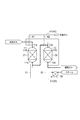
- FIG. 1 is a diagram for explaining some steps in an example of a carbon dioxide production method.
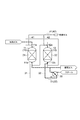
- FIG. 2 is a diagram for explaining some steps in an example of the carbon dioxide production method.
- FIG. 3 is a diagram for explaining some steps in an example of the carbon dioxide production method.
- FIG. 4 is a diagram for explaining some steps in an example of the carbon dioxide production method.
- FIG. 5 is a figure for demonstrating some process in an example of the manufacturing method of carbon dioxide.
- FIG. 6 is a diagram for explaining some steps in an example of the carbon dioxide production method.
- FIG. 7 is a schematic view showing another example of the carbon dioxide producing apparatus.
- a method for producing carbon dioxide is a method for producing carbon dioxide that uses a plurality of adsorption towers containing an adsorbent that adsorbs impurities in a source gas containing carbon dioxide, and reduces impurities from the source gas. Then, there is a refining step for obtaining a purified gas in which carbon dioxide has a higher purity than the raw material gas. Then, at a predetermined timing, in parallel with this purification step, there is a drying step of filling at least one adsorption tower with an unused adsorbent and then drying the adsorbent using a part of the purified gas.
- the number of adsorption towers may be two, or three or more.
- the purification step can be continuously performed during the drying step by using an adsorption tower different from the adsorption tower performing the drying step. Therefore, carbon dioxide satisfying the product specification can be continuously produced by using the other part of the purified gas even during the drying process.
- the “unused adsorbent” in the present disclosure refers to an adsorbent that has not been used in the purification process.
- the raw material gas containing carbon dioxide is not particularly limited, and examples thereof include combustion gas such as boiler.
- the raw material gas may contain impurities in addition to carbon dioxide. Examples of impurities include water, oxygen, nitrogen, sulfur oxides, nitrogen oxides, carbon monoxide, hydrogen sulfide and hydrocarbons.
- the concentration of carbon dioxide in the raw material gas may be, for example, 95% by volume or more, and may be 98% by volume or more.
- adsorbents include commercially available activated carbon and zeolite. In terms of cost, the adsorbent may include activated carbon.
- the purification step and the drying step are performed in parallel. In the drying step, the adsorbent is dried using the purified gas obtained in the refining step.
- a purified gas in which impurities are reduced is used in an adsorption tower different from the adsorption tower packed with the adsorbent to be dried.
- the purified gas is a gas in which the concentration of impurities is lower than that of the raw material gas, and may be carbon dioxide produced in this embodiment.
- Purified gas for drying the adsorbent may be supplied from the lower part of the adsorption tower containing the adsorbent.
- the dry gas containing water desorbed from the adsorbent may be discharged from the upper part of the adsorption tower.
- the purified gas flows from the lower part to the upper part of the adsorption tower. With such a flow direction, vaporized water is smoothly discharged to the outside of the adsorption tower.
- the temperature of the purified gas used for drying may be 110°C or higher, or 120°C or higher, from the viewpoint of quickly drying the adsorbent.
- the temperature of the purified gas used for drying may be 200° C. or lower, 160° C. or lower, or 140° C. or lower from the viewpoint of preventing ignition of activated carbon and energy efficiency.
- the pressure of the purified gas used for drying may be, for example, atmospheric pressure to 1 MPa.
- the space velocity of the purified gas in the drying step may be 10 to 50 h ⁇ 1 .
- the time of the drying step may be, for example, 24-48 hours.
- the judgment of the end of the drying step can be made, for example, on the basis of the temperature or the dew point of the dry gas derived from the adsorption tower that has dried the adsorbent.
- the drying step may be terminated when the temperature of the drying gas reaches, for example, 100° C. or higher. In a modification, the drying process may be terminated when the temperature of the drying gas reaches 110°C or higher or 120°C or higher.
- the adsorption tower may be subsequently subjected to a purification step of reducing impurities contained in the raw material gas to obtain a purified gas.
- the purification step may be performed using a plurality of adsorption towers.
- the dew point of the purified gas under atmospheric pressure may be maintained at, for example, ⁇ 20° C. or lower.
- the dew point of the purified gas under atmospheric pressure may be maintained at -30°C or lower, or -40°C or lower.
- the purified gas obtained by the purification process can be the carbon dioxide produced in this embodiment.
- the purity of carbon dioxide produced in the present embodiment may be, for example, 99.5% by volume or more, and may be 99.9% by volume or more. However, the purity is not limited, and it is sufficient if the purity of carbon dioxide is higher than that of the raw material gas. Therefore, it may contain impurities.
- the “volume %” in the present disclosure is the volume ratio in the standard state (0° C., 1 atm).
- Liquefaction process of liquefying carbon dioxide obtained in the purification process may be performed. That is, in the production method of this embodiment, gaseous carbon dioxide or liquid carbon dioxide may be produced. By sufficiently lowering the dew point of the purified gas, it is possible to sufficiently suppress the solidification of water even if the liquefaction process is performed.
- the unused adsorbent contained in the adsorption tower is dried using an inert gas other than carbon dioxide, such as nitrogen gas or argon gas
- an inert gas other than carbon dioxide such as nitrogen gas or argon gas
- the purified gas is used for drying the unused adsorbent in the drying step. Therefore, the consumption of the inert gas can be reduced.
- An apparatus for producing carbon dioxide includes a plurality of adsorption towers containing an adsorbent that adsorbs impurities in a raw material gas containing carbon dioxide, and continues production of carbon dioxide using at least one adsorption tower.
- the above description of the manufacturing method can be applied to the carbon dioxide manufacturing apparatus of this embodiment.
- the supply unit may supply a part of carbon dioxide derived from the adsorption tower to the other adsorption tower as a purified gas.
- the supply unit includes, for example, a pipe for circulating the purified gas and a heating unit for heating the purified gas. By providing the heating unit, the unused adsorbent can be dried more quickly.
- the heating unit may be, for example, a heat exchanger using steam or hot oil as a heat source.
- the discharge unit includes, for example, a pipe through which a dry gas obtained by drying the adsorbent is passed.
- the supply part may be connected to the lower part of the adsorption tower, and the discharge part may be connected to the upper part of the adsorption tower. As a result, the adsorbent is dried by the purified gas (dry gas) rising in the adsorption tower, and the water content of the adsorbent can be smoothly reduced.
- the carbon dioxide production device may be equipped with a dehumidifying unit upstream of the plurality of adsorption towers.
- the dehumidifying section has a function of reducing the water content contained in the raw material gas. By providing the dehumidifying portion, it is possible to suppress condensation and solidification of water and corrosion of each device due to water and carbon dioxide, and to further facilitate the production of carbon dioxide.
- the carbon dioxide production device may be equipped with a post-treatment unit for liquefying or solidifying carbon dioxide on the downstream side of the adsorption tower.
- the post-treatment unit has a function of adjusting the temperature and pressure of carbon dioxide, and includes, for example, a compressor and a cooler.
- FIG. 1, FIG. 2, FIG. 3, FIG. 4, FIG. 5 and FIG. 6 are views for explaining some steps of the carbon dioxide production method.
- a carbon dioxide producing apparatus having a first adsorption tower 11 and a second adsorption tower 12 which are connected as the plurality of adsorption towers 10 so that the raw material gas sequentially flows is used.
- the raw material gas sequentially flows through the first adsorption tower 11 and the second adsorption tower 12, and purified gas is obtained (dotted line flow in FIG. 1).
- Adsorbents 21 and 22 are housed in the first adsorption tower 11 and the second adsorption tower 12, respectively. Impurities other than carbon dioxide contained in the raw material gas are adsorbed by the adsorbents 21 and 22.
- the purified gas is led out from a pipe connected to the bottom portion 12b of the second adsorption tower 12. In this way, the purification process is performed.
- This purified gas may be carbon dioxide gas as it is, or may be cooled by a cooling unit to be liquid carbon dioxide. Further, it may be dried ice after that.
- the obtained carbon dioxide may be introduced and stored in, for example, a tank.
- the introduction of the raw material gas into the first adsorption tower 11 is stopped and the raw material gas is introduced into the second adsorption tower 12.
- the use contained in the first adsorption tower 11 Remove the used adsorbent (stopping step). After taking out, the unused adsorbent is stored in the first adsorption tower 11.
- Such exchange of activated carbon may be performed periodically or when the concentration of impurities in the purified gas discharged from the first adsorption tower 11 increases.
- a part of the purified gas (carbon dioxide) derived from the bottom portion 12b of the second adsorption tower 12 is introduced into the heating unit 30 and heated.
- the heat source may be steam as shown in the figure, or may be hot oil.
- the purified gas heated to a predetermined temperature range in the heating unit 30 flows through the pipe 31 and is supplied into the first adsorption tower 11 from the bottom portion 11b of the first adsorption tower 11.
- the heating unit 30 and the pipe 31 constitute a purified gas supply unit.
- the purified gas supplied from the supply unit to the first adsorption tower 11 comes into contact with the unused adsorbent while rising in the first adsorption tower 11, and reduces the water content of the unused adsorbent.
- This purified gas (dry gas) containing water flows through the pipe 41 (exhaust part) connected to the top part 11a of the first adsorption tower 11, and is exhausted into the atmosphere, for example (dotted line flow in FIG. 3).
- the purified gas derived from the bottom portion 12b of the second adsorption tower 12 can be continuously produced as carbon dioxide (broken line flow in FIG. 3).
- the production of purified gas is started in the first adsorption tower 11 (operation start process).
- the end of the drying may be determined by, for example, the temperature or the dew point of the dry gas that is discharged from the top 11a of the first adsorption tower 11.
- the temperature of the dry gas reaches 100° C. or higher
- the supply of the heated purified gas from the bottom portion 11b of the first adsorption tower 11 may be stopped.
- the temperature of the dry gas reaches 110° C. or higher, or 120° C. or higher, the supply of the heated purified gas from the bottom portion 11b of the first adsorption tower 11 may be stopped.
- the purified gas derived from the bottom portion 12b of the second adsorption tower 12 is introduced from the top portion 11a of the first adsorption tower 11 (FIG. 4).
- the unused adsorbent 21 contained in the first adsorption tower 11 starts adsorbing impurities.
- the purified gas obtained from the bottom portion 11b of the first adsorption tower 11 can be obtained as carbon dioxide.
- FIG. 4 shows the purification process after the operation start process of the first adsorption tower 11.
- the raw material gas flows through the second adsorption tower 12 and the first adsorption tower 11 in this order to obtain a refined gas (dotted line in FIG. 4).
- the timing for starting the operation starting step of the first adsorption tower 11 is not particularly limited after the drying step of the first adsorption tower 11, and the first adsorption tower 11 may be suspended for a while after the drying step.
- the adsorption capacity of the adsorbent 22 of the second adsorption tower 12 on the upstream side gradually decreases.
- the impurity concentration of the purified gas derived from the second adsorption tower 12 rises, the adsorbent 22 of the second adsorption tower 12 is replaced by the following procedure.
- the introduction of the raw material gas into the second adsorption tower 12 is stopped, and the raw material gas is introduced into the first adsorption tower 11. While the introduction of the raw material gas into the first adsorption tower 11 and the derivation of the purified gas from the first adsorption tower 11 (production of carbon dioxide) are continued (broken line flow in FIG. 5), they are accommodated in the second adsorption tower 12. Remove the used adsorbent that had been used (stop process). After taking out, the unused adsorbent is stored in the second adsorption tower 12.
- a part of the purified gas (carbon dioxide) derived from the bottom portion 11 b of the first adsorption tower 11 is introduced into the heating unit 30.
- the purified gas heated to a predetermined temperature or higher in the heating unit 30 flows through the pipe 32 and is supplied into the second adsorption tower 12 from the bottom portion 12b of the second adsorption tower 12.
- the heating unit 30 and the pipe 32 constitute a supply unit for the purified gas.
- the purified gas supplied from the supply unit to the second adsorption tower 12 contacts the unused adsorbent while rising in the second adsorption tower 12, and reduces the moisture content of the unused adsorbent.
- the purified gas containing water (dry gas) flows through the pipe 42 (exhaust part) connected to the top portion 12a of the second adsorption tower 12 and is exhausted into the atmosphere, for example (dotted line in FIG. 6). Even during this drying step, the purified gas derived from the bottom portion 11b of the first adsorption tower 11 can be continuously produced as carbon dioxide (broken line flow in FIG. 6).
- the production of purified gas is started in the second adsorption tower 12 (operation start process).
- the completion of the drying may be determined, for example, by the temperature or the dew point of the dry gas that is discharged from the top portion 12a of the second adsorption tower 12.
- the supply of the heated purified gas from the bottom portion 12b of the second adsorption tower 12 is stopped.
- the purified gas derived from the bottom 11 b of the first adsorption tower 11 is introduced from the top 12 a of the second adsorption tower 12.
- the purified gas obtained from the bottom 12b of the second adsorption tower 12 can be used as carbon dioxide.
- FIG. 7 is a schematic diagram showing another example of a carbon dioxide production apparatus.
- the manufacturing apparatus in FIG. 7 is an apparatus for manufacturing carbon dioxide from exhaust gas from a boiler or the like.
- This manufacturing apparatus includes a desulfurization tower 50, an absorption tower 60, a regeneration tower 80, a compressor 90, a dehumidifying section 95, and an adsorption tower 10.
- the exhaust gas is introduced into the desulfurization tower 50.
- the desulfurization tower 50 removes, for example, sulfur oxides contained in exhaust gas. For example, an alkaline aqueous solution is supplied to the desulfurization tower 50.
- the exhaust gas and the alkaline aqueous solution are in gas-liquid contact with each other, and the sulfur oxide is absorbed in the alkaline aqueous solution.
- the alkaline aqueous solution include calcium carbonate aqueous solution, sodium hydroxide aqueous solution, magnesium hydroxide aqueous solution, and ammonia water.
- the exhaust gas that has passed through the desulfurization tower 50 is supplied to the absorption tower 60.
- carbon dioxide is recovered from the exhaust gas by the chemical absorption method.
- the absorption tower 60 makes the absorption liquid absorb the carbon dioxide contained in the exhaust gas by bringing the exhaust gas generated in the boiler and the like into contact with the absorption liquid that absorbs the carbon dioxide.
- the absorption liquid is supplied to the absorption tower 60 from a flow path 84 connected to the upper part thereof.
- the absorbing liquid is a liquid that absorbs carbon dioxide and is, for example, an amine aqueous solution.
- the amine aqueous solution include aqueous solutions of MEA (monoethanolamine), EAE (ethylaminoethanol), IPAE (isopropaaminoethanol), TMDAH (tetramethyldiaminohexane), and the like.
- the raw material gas rises as the absorbing liquid falls.
- the absorption liquid and the source gas come into countercurrent contact, and the carbon dioxide contained in the source gas is absorbed by the absorption liquid.
- the amount of carbon dioxide absorbed by the absorbing liquid depends on the temperature. Therefore, by controlling the temperature in the absorption tower 60, the absorption amount of carbon dioxide by the absorption liquid can be adjusted.
- the absorbing liquid descends while making gas-liquid contact with the exhaust gas, and absorbs carbon dioxide contained in the exhaust gas (absorption process).
- the gas from which the carbon dioxide has been reduced or removed (off-gas) is discharged from the top of the absorption tower 60 and introduced into the cleaning tower 65. Water is supplied to the cleaning tower 65 through a flow path (not shown).
- the cleaning tower 65 the trace components contained in the gas are removed by bringing the gas and water into contact with each other.
- the gas cleaned by the cleaning tower 65 may be released to the atmosphere, or may be used for various purposes depending on the contained components.
- the temperature in the absorption tower 60 can be set, for example, according to the type of absorbing liquid, and is, for example, 30 to 40°C.
- the pressure in the absorption tower 60 is, for example, 0 to 1.0 MPa.
- the absorption liquid (rich liquid) that has absorbed carbon dioxide in the absorption tower 60 is stored in the tower bottom of the absorption tower 60, and is discharged from the absorption tower 60 at 30 to 40° C. by the flow path 62 connected to the tower bottom. It The absorption liquid discharged from the absorption tower 60 is introduced into the heat exchanger 70 via a pump. Here, heat is exchanged with the absorbing liquid (lean liquid) discharged from the regeneration tower 80 through the flow path 83 and heated to, for example, 80 to 90°C. The absorption liquid heated by the heat exchanger 70 flows through the flow path 64 and is introduced into the regeneration tower 80. The flow path 64 is connected to the upper part of the regeneration tower 80.
- the absorbing liquid flowing down in the regeneration tower 80 stays on a tray (not shown) provided at or near the tower bottom in the regeneration tower 80.
- a reboiler 81 that heats the absorption liquid accumulated at or near the bottom of the regeneration tower 80 is provided outside the regeneration tower 80.
- the absorption liquid accumulated on the tray is introduced into the reboiler 81, exchanges heat with a heat medium (for example, steam), and is heated to, for example, 80 to 130° C.
- the absorption liquid heated by the reboiler 81 returns to the inside of the regeneration tower 80.
- a flow path 83 for discharging the absorption liquid (lean liquid) with reduced carbon dioxide from the regeneration tower 80 is connected.
- the absorbing liquid (lean liquid) flows through the flow path 83, is introduced into the heat exchanger 70, and is cooled by heat exchange with the absorbing liquid (rich liquid) from the absorption tower 60.
- the absorbing liquid (lean liquid) cooled in the heat exchanger 70 flows through the flow path 84 and is introduced into the cooler 82, where it is cooled to, for example, 30 to 40° C.
- the absorption liquid (lean liquid) is supplied to the upper part of the absorption tower 60. In this way, the absorption liquid is used while circulating between the absorption tower 60 and the regeneration tower 80.
- the gas containing carbon dioxide and impurities separated from the absorption liquid rises in the regeneration tower 80 and is discharged from the top of the regeneration tower 80 as a raw material gas for the adsorption tower 10.
- the raw material gas is discharged from the top of the regeneration tower 80 at a temperature of 85 to 95° C., introduced into a heat exchanger, and cooled to 30 to 50° C. by heat exchange with water, for example.
- the condensate produced by cooling is used as a reflux in the regeneration tower 80.
- the raw material gas cooled by the heat exchanger is introduced into the compressor 90 and is pressurized to, for example, 0.8 to 1 MPa.
- the source gas whose pressure has been increased by the compressor 90 is introduced into the dehumidifying section 95.
- the dehumidifying section 95 has a dehumidifying material such as activated alumina or zeolite.
- the raw material gas dehumidified in the dehumidifying section 95 is introduced into the adsorption tower 10 containing the adsorbent.
- the adsorption tower 10 may have a configuration including two adsorption towers as shown in FIGS. 1 to 6 or may have another configuration.
- the carbon dioxide production apparatus as shown in FIG. 7 can smoothly increase the production amount of high-purity carbon dioxide from the exhaust gas containing carbon dioxide.
- a catalyst tower containing a reduction catalyst may be provided on the upstream side of the adsorption tower 10.
- the raw material gas is brought into contact with the reduction catalyst in a hydrogen atmosphere, whereby impurities contained in the raw material gas are reduced, and the purity of carbon dioxide can be further improved.
- a known deoxidizing catalyst can be used as the reducing catalyst used in the catalyst tower.
- a catalyst in which a noble metal is supported on a carrier can be used.
- carriers include aluminum oxide and magnesium oxide.
- noble metals include platinum, palladium, rhodium, ruthenium and alloys thereof.
- the above-mentioned one kind may be used alone, or two or more kinds may be combined. Since the carbon dioxide produced by the above-mentioned production apparatus or production method has a reduced odor, it can be suitably used for beverages or foods.
- Example 1 The used activated carbon was replaced in the carbon dioxide producing apparatus in the operating state shown in FIG.
- the exchange was performed as shown in FIG. That is, the introduction of the raw material gas into the first adsorption tower 11 was stopped, and the raw material gas was introduced into the second adsorption tower 12. While continuing the production of carbon dioxide in the second adsorption tower 12, the used activated carbon contained in the first adsorption tower 11 was taken out. After taking out, unused activated carbon was stored in the first adsorption tower 11.
- the unused activated carbon was dried as shown in Fig. 3. That is, a part (about 20% by volume of the total amount) of carbon dioxide derived from the bottom portion 12b of the second adsorption tower 12 was introduced into the heating unit 30 as purified gas and heated. Steam was used as the heat source. The purified gas heated to 120 to 130° C. by the heating unit 30 was supplied into the first adsorption tower 11 from the bottom 11b of the first adsorption tower 11. From the time when the step (flow) shown in FIG. 3 was started, the temperature and the dew point of the lower part and the upper part of the first adsorption tower 11 were monitored.
- Adsorption tower 11... 1st adsorption tower, 11a, 12a... Top part, 11b, 12b... Bottom part, 12... 2nd adsorption tower 21,22... Adsorbent, 30... Heating part, 31, 32, 41, 42 ... Piping, 50... Desulfurization tower, 60... Absorption tower, 62, 64, 83, 84... Flow path, 65... Washing tower, 70... Heat exchanger, 80... Regeneration tower, 81... Reboiler, 82... Cooler, 90... Compressor, 95... Dehumidifying section.
Landscapes
- Chemical & Material Sciences (AREA)
- Chemical Kinetics & Catalysis (AREA)
- Organic Chemistry (AREA)
- Engineering & Computer Science (AREA)
- Analytical Chemistry (AREA)
- General Chemical & Material Sciences (AREA)
- Oil, Petroleum & Natural Gas (AREA)
- Inorganic Chemistry (AREA)
- Carbon And Carbon Compounds (AREA)
- Separation Of Gases By Adsorption (AREA)
Abstract
L'invention porte sur un procédé de production de dioxyde de carbone qui utilise une pluralité de tours d'adsorption qui accueillent un adsorbant qui adsorbe les impuretés dans une charge gazeuse contenant du dioxyde de carbone. Ledit procédé de production de dioxyde de carbone comporte une étape de séchage dans laquelle, alors que le dioxyde de carbone est produit en continu en utilisant au moins une tour d'adsorption, une partie d'un gaz raffiné obtenu par réduction des impuretés du gaz d'alimentation est utilisée pour sécher l'adsorbant qui a été chargé dans une tour d'adsorption différente de la ou des tours d'adsorption.
Applications Claiming Priority (2)
| Application Number | Priority Date | Filing Date | Title |
|---|---|---|---|
| JP2019-036382 | 2019-02-28 | ||
| JP2019036382A JP6855525B2 (ja) | 2019-02-28 | 2019-02-28 | 二酸化炭素の製造方法 |
Publications (1)
| Publication Number | Publication Date |
|---|---|
| WO2020174858A1 true WO2020174858A1 (fr) | 2020-09-03 |
Family
ID=72239317
Family Applications (1)
| Application Number | Title | Priority Date | Filing Date |
|---|---|---|---|
| PCT/JP2019/050646 Ceased WO2020174858A1 (fr) | 2019-02-28 | 2019-12-24 | Procédé de production de dioxyde de carbone et dispositif de production de dioxyde de carbone |
Country Status (2)
| Country | Link |
|---|---|
| JP (1) | JP6855525B2 (fr) |
| WO (1) | WO2020174858A1 (fr) |
Families Citing this family (2)
| Publication number | Priority date | Publication date | Assignee | Title |
|---|---|---|---|---|
| TWI843179B (zh) * | 2022-08-12 | 2024-05-21 | 細胞製氣科技股份有限公司 | 二氧化碳純化系統 |
| KR102784491B1 (ko) * | 2022-10-20 | 2025-03-19 | 황철용 | 이산화탄소 포집 시스템 및 이를 이용한 이산화탄소 포집 방법 |
Citations (5)
| Publication number | Priority date | Publication date | Assignee | Title |
|---|---|---|---|---|
| JPH1059705A (ja) * | 1996-08-14 | 1998-03-03 | Agency Of Ind Science & Technol | 炭酸ガスの分離・回収方法 |
| JP2000225183A (ja) * | 1999-02-09 | 2000-08-15 | Iwatani Internatl Corp | ガス精製系での再生用ガスの回収方法 |
| CN201684526U (zh) * | 2009-11-27 | 2010-12-29 | 胜利油田胜利勘察设计研究院有限公司 | Co2气体干燥装置 |
| JP2017170379A (ja) * | 2016-03-25 | 2017-09-28 | 株式会社Ihi | 二酸化炭素の回収方法及び回収装置 |
| CN207566890U (zh) * | 2017-12-05 | 2018-07-03 | 天津永利食用添加剂有限公司 | 保证脱水效率的食品添加剂液体二氧化碳生产线 |
-
2019
- 2019-02-28 JP JP2019036382A patent/JP6855525B2/ja active Active
- 2019-12-24 WO PCT/JP2019/050646 patent/WO2020174858A1/fr not_active Ceased
Patent Citations (5)
| Publication number | Priority date | Publication date | Assignee | Title |
|---|---|---|---|---|
| JPH1059705A (ja) * | 1996-08-14 | 1998-03-03 | Agency Of Ind Science & Technol | 炭酸ガスの分離・回収方法 |
| JP2000225183A (ja) * | 1999-02-09 | 2000-08-15 | Iwatani Internatl Corp | ガス精製系での再生用ガスの回収方法 |
| CN201684526U (zh) * | 2009-11-27 | 2010-12-29 | 胜利油田胜利勘察设计研究院有限公司 | Co2气体干燥装置 |
| JP2017170379A (ja) * | 2016-03-25 | 2017-09-28 | 株式会社Ihi | 二酸化炭素の回収方法及び回収装置 |
| CN207566890U (zh) * | 2017-12-05 | 2018-07-03 | 天津永利食用添加剂有限公司 | 保证脱水效率的食品添加剂液体二氧化碳生产线 |
Also Published As
| Publication number | Publication date |
|---|---|
| JP6855525B2 (ja) | 2021-04-07 |
| JP2020138889A (ja) | 2020-09-03 |
Similar Documents
| Publication | Publication Date | Title |
|---|---|---|
| US10960343B2 (en) | Methods and systems for performing chemical separations | |
| RU2509720C2 (ru) | Способ получения водорода с полным улавливанием co2 и рециклом непрореагировавшего метана | |
| JP5906074B2 (ja) | 水素製造システム | |
| CN102410703A (zh) | 改进的食品级液体二氧化碳产品的生产方法及蒸馏提纯塔 | |
| JP5743215B2 (ja) | ヘリウムガスの精製方法および精製装置 | |
| CN102602899B (zh) | 氦气的纯化方法及纯化装置 | |
| JP5729765B2 (ja) | ヘリウムガスの精製方法および精製装置 | |
| JP6576288B2 (ja) | 二酸化炭素ガスの回収装置、及び、二酸化炭素ガスの製造方法 | |
| JP6855525B2 (ja) | 二酸化炭素の製造方法 | |
| JP5683390B2 (ja) | ヘリウムガスの精製方法および精製装置 | |
| JP5748272B2 (ja) | ヘリウムガスの精製方法および精製装置 | |
| JP5791113B2 (ja) | アルゴンガスの精製方法および精製装置 | |
| JP5745434B2 (ja) | アルゴンガスの精製方法および精製装置 | |
| JP2010209296A (ja) | 原料ガス中の有機硫黄化合物の除去方法及びそれに使用する触媒 | |
| CN102639437A (zh) | 在处理合成气的方法中在co2产物料流中维持降低的co | |
| JP5403685B2 (ja) | アルゴンガスの精製方法および精製装置 | |
| JP2018515327A (ja) | ガス流から二酸化炭素を分離するための装置及び方法 | |
| US20120144860A1 (en) | Process for removing harmful substances from liquid carbon dioxide and apparatus for the performance thereof | |
| JP4382770B2 (ja) | 二酸化炭素の精製方法 | |
| JP6800622B2 (ja) | 精製ガスの製造方法および精製ガスの製造装置 | |
| JP2005177716A (ja) | 水素psa精製装置から排出されるオフガスの処理方法 | |
| JP5761751B2 (ja) | アルゴンガスの精製方法および精製装置 | |
| JP7650767B2 (ja) | 二酸化炭素回収装置及び二酸化炭素回収方法 | |
| JP2010174191A (ja) | 天然ガス処理における酸素消費量の低減方法 | |
| CN117511617A (zh) | 一种天然气净化工艺 |
Legal Events
| Date | Code | Title | Description |
|---|---|---|---|
| 121 | Ep: the epo has been informed by wipo that ep was designated in this application |
Ref document number: 19917270 Country of ref document: EP Kind code of ref document: A1 |
|
| NENP | Non-entry into the national phase |
Ref country code: DE |
|
| 122 | Ep: pct application non-entry in european phase |
Ref document number: 19917270 Country of ref document: EP Kind code of ref document: A1 |