WO2020178933A1 - シミュレーションシステム - Google Patents
シミュレーションシステム Download PDFInfo
- Publication number
- WO2020178933A1 WO2020178933A1 PCT/JP2019/008310 JP2019008310W WO2020178933A1 WO 2020178933 A1 WO2020178933 A1 WO 2020178933A1 JP 2019008310 W JP2019008310 W JP 2019008310W WO 2020178933 A1 WO2020178933 A1 WO 2020178933A1
- Authority
- WO
- WIPO (PCT)
- Prior art keywords
- connection
- module data
- module
- data
- simulation
- Prior art date
- Legal status (The legal status is an assumption and is not a legal conclusion. Google has not performed a legal analysis and makes no representation as to the accuracy of the status listed.)
- Ceased
Links
Images


Classifications
-
- B—PERFORMING OPERATIONS; TRANSPORTING
- B25—HAND TOOLS; PORTABLE POWER-DRIVEN TOOLS; MANIPULATORS
- B25J—MANIPULATORS; CHAMBERS PROVIDED WITH MANIPULATION DEVICES
- B25J9/00—Program-controlled manipulators
- B25J9/16—Program controls
- B25J9/1602—Program controls characterised by the control system, structure, architecture
- B25J9/1605—Simulation of manipulator lay-out, design, modelling of manipulator
-
- G—PHYSICS
- G05—CONTROLLING; REGULATING
- G05B—CONTROL OR REGULATING SYSTEMS IN GENERAL; FUNCTIONAL ELEMENTS OF SUCH SYSTEMS; MONITORING OR TESTING ARRANGEMENTS FOR SUCH SYSTEMS OR ELEMENTS
- G05B17/00—Systems involving the use of models or simulators of said systems
- G05B17/02—Systems involving the use of models or simulators of said systems electric
-
- G—PHYSICS
- G05—CONTROLLING; REGULATING
- G05B—CONTROL OR REGULATING SYSTEMS IN GENERAL; FUNCTIONAL ELEMENTS OF SUCH SYSTEMS; MONITORING OR TESTING ARRANGEMENTS FOR SUCH SYSTEMS OR ELEMENTS
- G05B2219/00—Program-control systems
- G05B2219/30—Nc systems
- G05B2219/34—Director, elements to supervisory
- G05B2219/34459—Plausibility check on connection of module, control unit to machine
-
- G—PHYSICS
- G05—CONTROLLING; REGULATING
- G05B—CONTROL OR REGULATING SYSTEMS IN GENERAL; FUNCTIONAL ELEMENTS OF SUCH SYSTEMS; MONITORING OR TESTING ARRANGEMENTS FOR SUCH SYSTEMS OR ELEMENTS
- G05B2219/00—Program-control systems
- G05B2219/30—Nc systems
- G05B2219/40—Robotics, robotics mapping to robotics vision
- G05B2219/40324—Simulation, modeling of muscle, musculoskeletal dynamical system
Definitions
- This specification discloses a simulation system.
- Patent Document 1 describes a system in which a tool is connected to a tool holder of an arm by plug and play to build a simulation model and perform the simulation.
- connection is made by plug and play, but no specific connection information or connection method is mentioned. Since there are various types of modules such as tool holders and tools that are attached to and detached from the robot, and their connection configurations are diversified, there are cases in which module data cannot be connected to each other. On the other hand, if the user of the simulation system or the like determines whether or not to connect them, it may take time or make a mistake in the determination.
- the main purpose of the present disclosure is to appropriately confirm whether or not the module data can be connected to each other and to perform the simulation promptly.
- the present disclosure has adopted the following means in order to achieve the main purpose described above.
- the simulation system of the present disclosure is A simulation system for executing a simulation using a model constructed by module data of each of a plurality of modules, A storage unit that stores connection relationship information that defines a relationship between the module data that can be connected to each other. When a plurality of the module data is selected, a confirmation unit that confirms whether or not the module data can be connected to each other based on the connection relationship information, The main point is to provide.
- connection relationship information that defines the relationship of the module data that can be connected to each other is stored, and when a plurality of module data is selected, whether or not the module data can be connected is determined based on the connection relationship information. Check. As a result, it is possible to appropriately confirm whether the module data can be connected to each other without causing the user of the simulation system to judge whether the connection is possible. Therefore, the model can be appropriately constructed from the module data and the simulation can be performed quickly.
- Explanatory drawing which shows the outline of marketplace MP.
- the block diagram which shows the outline of a structure of the work system 60.
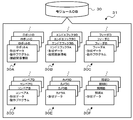
- Explanatory drawing which shows an example of module DB30.
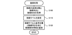
- the flowchart which shows an example of a registration process.
- Explanatory drawing which shows an example of connection relationship information.
- the flowchart which shows an example of a connection process at the time of model construction.
- Explanatory drawing which shows an example of a mode that module data is automatically connected.
- the flowchart which shows an example of the connection display process at the time of model construction.
- Explanatory drawing which shows the modification of the mode which connects module data automatically.
- FIG. 1 is a configuration diagram showing an outline of the configuration of a facility introduction support system 10 of the present embodiment
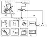
- FIG. 2 is an explanatory diagram showing an outline of a marketplace MP
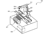
- FIG. 3 shows an outline of a configuration of a work system 60.
- the facility introduction support system 10 includes a management server 20 that manages a marketplace MP for customers to purchase various facilities and devices (hereinafter, modules) provided by a vendor. ..
- a management server 20 is connected to a vendor terminal 40 and a customer terminal 50 via a network 12.
- FIG. 1 one vendor terminal 40 and one customer terminal 50 are shown, but a plurality of vendor terminals 40 and customer terminals 50 are actually connected.
- the management server 20 includes a control unit 21, a simulation unit 22, a storage unit 23, and a communication unit 26.
- the control unit 21 has a CPU, a ROM, a RAM, etc., and controls the entire server such as management of the marketplace MP.
- the simulation unit 22 constructs a model MD (digital twin, see FIG. 2) such as a work system 60 (see FIG. 3) in which modules that can be purchased at the marketplace MP are combined in a virtual space, and the model MD is created in the virtual space. Run a simulation using.
- the simulation unit 22 also connects the modules to each other when constructing the model MD.
- the storage unit 23 includes an HDD and stores various application programs and various databases (DB).
- the communication unit 26 is connected to the network 12 or the like and communicates with the vendor terminal 40 or the customer terminal 50.
- Various instructions from the administrator are input to the management server 20 from the input unit 28 such as a keyboard and a mouse. Further, the management server 20 displays various information on the display unit 29 such as a display.
- the management server 20 is not limited to one including the simulation unit 22 and the storage unit 23 (various DBs), and the simulation unit may be configured as another device capable of communicating with the management server 20 or stores various DBs.
- the data server may be configured as another device capable of communicating with the management server 20.
- the vendor terminal 40 is connected to the control unit 41 having a CPU, a ROM, a RAM, a storage unit 43 such as an HDD for storing various application programs and various data, and is connected to the network 12 and communicates with the management server 20 and the like. And a communication unit 46.
- Various instructions from the vendor are input to the vendor terminal 40 from the input unit 48 such as a keyboard and a mouse. Further, the vendor terminal 40 displays various information such as a registration screen for registering the module data of the module to be provided in the marketplace MP on the display unit 49 such as a display.
- the customer terminal 50 includes a control unit 51, a storage unit 53, and a communication unit 56.
- the communication unit 56 may communicate with the control device 68 of the work system 60, which will be described later, via the network 12 or the like.
- Various instructions and the like by the customer are input to the customer terminal 50 from the input unit 58 such as a keyboard and a mouse. Further, the customer terminal 50 displays various information such as the top screen (purchase screen) of the marketplace MP, the simulation model MD, and the simulation execution result on the display unit 59 such as a display.
- the work system 60 can be configured as a system in which a robot 61 performs a predetermined work, and in the example of FIG. 3, in addition to the robot 61, a substrate transfer device 66 and a feeder 67 are provided.
- An example of the predetermined work is, for example, a mounting work in which the robot 61 picks up a work such as a mechanical component or an electronic component and mounts it on the substrate S.
- the robot 61 includes a vertical articulated robot arm 62 and a control device 68 that controls the entire system including the operation of the robot arm 62.
- an end effector 63 as a work tool is detachably attached to the tip end link of the robot arm 62, and a camera 64 for picking up an image and an illumination 65 such as a ring light arranged coaxially with the camera 64 are attached.
- the end effector 63 may be an electromagnetic chuck, a mechanical chuck, a suction nozzle, or the like.
- the substrate transfer device 66 transfers the substrate S by a pair of belt conveyors.
- the feeder 67 is configured as a tape feeder that feeds out a tape containing a plurality of works at predetermined intervals. Note that the feeder 67 is not limited to a tape feeder, and may be a tray feeder or the like that supplies a tray on which a plurality of works are arranged.
- the control device 68 is composed of a CPU, a ROM, an HDD, a RAM, and the like, and stores, in addition to the operation program of the robot 61, a system program that manages the entire work system 60.
- the operation program of the board transfer device 66 is stored in the PLC (Programmable Logic Controller) of the board transfer device 66
- the operation program of the feeder 67 is stored in the PLC of the feeder 67.
- the robot 61 robot arm 62
- the end effector 63, the camera 64, the lighting 65, the substrate transfer device 66, and the feeder 67 that form the work system 60 are called modules.
- the storage unit 23 of the management server 20 stores a module DB (database) 30, a vendor DB 37, and a customer DB 39 shown in FIG.
- the vendor DB 37 has registered therein the names of the vendors who have been certified and registered, vendor IDs unique to each vendor, contact information such as email addresses and addresses, and information on the types of modules provided by the vendors.
- the customer DB 39 is registered with the name of the customer for whom authentication registration has been made, the customer ID unique to each customer, contact information such as an e-mail address and address, and the purchase history of the customer.
- the module DB 30 registers module data and the like registered by the vendor from the vendor terminal 40 via the registration screen, and a plurality of module data 31 are registered for each module type. For example, as shown in FIG. 4, the plurality of module data 31 are classified and registered into robot data 30A, end effector data 30B, feeder data 30C, conveyor data 30D, camera data 30E, and illumination data 30F. Module data of the robot arm 62 (robot A) and module data of other various robots B to D are registered in the robot data 30A.
- the various robots may be of a horizontal articulated type or a parallel link type other than the vertical articulated type.
- Each of these module data includes shape data such as three-dimensional CAD data of robots A to D, an operation program, connection relationship information that defines a connection relationship with other modules, specifications, and the like.
- the end effector data 30B includes shape data and connections of the end effector 63 (end effector A) that can be attached to and detached from (connected to) the robot A (end effector A) and other types of end effectors B to D that can be attached to and detached from the robots A to D.
- Module data including related information and specifications are registered.
- the feeder data 30C module data including shape data of the feeder 67 (feeder A) and other types of feeders B to D, an operation program, and the like is registered.
- module data including shape data, operation programs, specifications, etc. of the conveyor A as the board transfer device 66 and other types of conveyors are registered.
- Module data including shape data and specifications of the camera 64 (camera A) and other types of cameras B to D are registered in the camera data 30E.
- Module data including shape data and specifications of the illumination 65 (illumination A) and other types of illuminations B to D is registered in the illumination data 30F.
- the module DB 30 is also registered with module data including shape data and physical property data of a typical work to be worked.
- the work module data may be registered by a vendor or an administrator who receives a request from a customer, and is used in a simulation using the model MD.
- a module selection screen (not shown) for displaying a list of applicable types of module data is displayed. To be done.
- each module data 31 of the robots A to D is displayed in a list, and the customer can select and purchase a required module from the list.
- the module data displayed as a list is registered in the module DB 30.
- a tool selection screen (not shown) for displaying a list of various tools in a selectable manner is displayed. Customers can select and purchase the necessary tools from among them.
- an analysis tool that collects and analyzes information such as the work status of each module and the frequency of occurrence of abnormalities
- a proposal tool that proposes improvement plans such as module changes based on the analysis results
- an efficient module Examples include layout tools that perform layout.
- the customer can select the module icon or the tool icon without clicking the purchase button to browse the contents of the listed modules or tools. Further, when the customer logs in to My Page, the customer can check the purchase history of the module, the content and change history of the module to be introduced, the contact information from the management server 20 and the vendor, and the like.
- FIG. 5 is a flowchart showing an example of the registration process
- FIG. 6 is an explanatory diagram showing an example of the connection relation information.
- the registration process is executed by the control unit 21 of the management server 20 when a connectable module such as a robot or an end effector is registered through the registration screen displayed on the display unit 49 of the vendor terminal 40. It When registering a module connectable to another module, the vendor inputs the following various information necessary for connection.
- the control unit 21 of the management server 20 first acquires each information of the reference position of the module connection, the connection direction, and the connection shape (S100), and sets the connection label (label information) indicating the connection shape. (S110).
- the reference position, connection direction, and connection shape information acquired by the vendor are acquired.
- the information on the connection shape for example, information on whether the shape of the connecting convex portion provided on the end effector is cylindrical or conical, or the outer diameter or the tip of the base end of the convex portion Information on the size of the convex portion such as the outer diameter and the convex height is acquired. Similar information is obtained for the connection recess.
- the connection relation information including the set connection label and each information acquired in S100 is registered in the module data (S120), and the registration process is ended.
- connection label “1- ⁇ ” indicating the connection shape A, the connection reference position Pa, and the connection orientation information are registered in the connection relation information in the module data of the robot A.
- the connection shape indicates the shape of the tip link (connection surface) in the robot arm 62 of the robot A, and, for example, the shape, size, position, etc. of the concave portion into which the cylindrical or conical convex portion provided in the end effector is fitted. This is the information to be shown.
- the reference position Pa is a reference position when connecting another module such as an end effector, such as a connection center position of the tip link.
- connection direction indicates the direction of the tip link when connected to another module in the XYZ coordinate system having the reference position Pa as the origin.
- the connection label "2- ⁇ ", the connection reference position Pb, and the connection orientation information are registered in the connection relationship information.
- the connection relationship information is also registered in the end effector connected to the robot. For example, in the connection relation information in the module data of the end effector A, the connection label “1- ⁇ 1” indicating that it corresponds to the connection shape A, the connection reference position pa1, and the connection orientation information are registered. ..
- connection label "2- ⁇ 1" indicates a connectable relationship
- connection label "2- ⁇ ” and the connection label "2- ⁇ 1” indicate a connectable relationship. .. That is, in the connection label of the present embodiment, the leading numbers indicate the corresponding connection relationships, and ⁇ and ⁇ indicate the robot and the end effector, respectively. If there are a plurality of end effectors connectable to the same robot, the numbers after ⁇ are set in order from the value 1.
- FIG. 6B shows a state in which the connection relation information of the end effector E is newly added from the state of FIG. 6A.
- the connection label “1- ⁇ 2” is set by the control unit 21, and the connection label, the connection reference position Pe, and the connection orientation are set. Information is registered in the connection relation information.
- the connection relationship information of new module data can be additionally stored.
- FIG. 6B illustrates the case where the end effector E connectable to the robot A is added, the present invention is not limited to this, and a combination of a new robot and an end effector connectable thereto may be additionally stored. Is also possible.
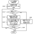
- FIG. 7 is a flowchart showing an example of connection processing at the time of model construction.
- This model construction connection process is a process performed on module data including connection relationship information when the simulation unit 22 constructs a model MD using, for example, a plurality of module data selected by the customer.
- the simulation unit 22 executes this processing when a plurality of robots, end effectors, or the like are selected as modules.
- the simulation unit 22 first acquires module data including connection relationship information (S200), and determines whether there is module data with a matching connection label (S210).
- the simulation unit 22 determines that there is module data in which the connection labels match when the first number of the connection label included in the module data of the robot and the connection label included in the module data of the end effector are the same.
- the simulation unit 22 respectively acquires the information on the connection reference position and the connection orientation of the matching module data (S220). Next, the simulation unit 22 automatically connects the module data to each other by matching the reference positions with each other and aligning the connection directions (S230).
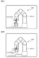
- FIG. 8 is an explanatory diagram showing an example of how module data is automatically connected.
- the robot A and the end effector A are simplified and shown.
- the reference position Pa (X0, Y0, Z0) of the tip link in the robot arm 62 and the connection direction of the XYZ coordinate system whose origin is the reference position Pa are determined.
- the Y coordinate is a direction perpendicular to the paper surface and is not shown.
- the reference position pa1 x0, y0, z0
- connection direction of the xyz coordinate system whose origin is the reference position pa1 are defined.
- the y-coordinate is a direction perpendicular to the plane of the drawing and is not shown.
- the simulation unit 22 matches the reference position Pa of the robot A with the reference position pa1 of the end effector A, and each axis (X axis, x axis, Y axis) of the XYZ coordinate system of the robot A and the xyz coordinate system of the end effector A.
- the end effector A is automatically connected to the robot A by aligning the directions so that the axes and the y-axis and the Z-axis and the z-axis coincide with each other (see FIG. 8B).
- the Y axis and the y axis are assumed to coincide with each other in the direction perpendicular to the paper surface.
- the simulation unit 22 automatically connects the end effector to the robot on the digital twin, the simulation user does not need to connect.
- the simulation unit 22 determines whether or not there is other unconnected module data (S240), and if it determines that there is unconnected module data, returns to S210. Further, when the simulation unit 22 determines in S210 that there is module data whose connection labels do not match, the simulation unit 22 requests the control unit 21 to reselect the module because connection is not possible (S250), and ends the connection process at the time of model construction. .. For example, when the robot A having the connection label “1- ⁇ ” and the end effector B having the connection label “2- ⁇ 1” are selected, the simulation unit 22 determines that the connection is impossible and requests reselection. .. When the simulation unit 22 determines in S240 that there is no unconnected module data, the simulation unit 22 ends the model-building connection process.
- the facility introduction support system 10 of the present embodiment corresponds to a simulation system
- the storage unit 23 of the management server 20 corresponds to a storage unit
- the simulation unit 22 of the management server 20 that executes S210 of the model construction connection process of FIG. Corresponds to the confirmation section.
- the simulation unit 22 that executes S230 of the connection process during model construction corresponds to the connection unit.
- the equipment introduction support system 10 described above stores the connection relation information including the connection label defining the connection relation of the module data in the storage unit 23, and when a plurality of module data is selected, the module is based on the connection label. Check whether data can be connected to each other. For this reason, it is possible to easily confirm whether or not the module data can be connected without allowing the user to determine whether or not the connection is possible. Therefore, it is possible to appropriately construct the model MD from the module data and quickly perform the simulation.
- the equipment introduction support system 10 includes the reference position and the connection direction information in the connection relation information, and automatically connects the module data confirmed to be connectable by matching the reference position and aligning the connection direction. This can save the user the trouble of connecting the module data to each other, so that the simulation can be performed more quickly.
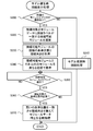
- FIG. 9 is a flowchart showing an example of the connection display process at the time of model construction
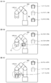
- FIG. 10 is an explanatory diagram showing a modified example of a state in which module data are automatically connected.
- the simulation unit 22 (display control unit) first determines whether or not there is a plurality of module data of the same type that can be connected to other module data as the module data for building the model MD. A determination is made (S300). In S300, the simulation unit 22 makes an affirmative determination when a plurality of module data of end effectors connectable to the robot are selected. When the simulation unit 22 determines in S300 that there are not a plurality of module data of the same type, the model-building connection process of FIG. 7 is executed (S310), and this process ends.
- the simulation unit 22 determines in S300 that there are a plurality of module data of the same type, the connectable module whose connection label matches the module data to be connected is selected (S320). Next, the simulation unit 22 acquires the reference position and connection direction of the connection from the module data of the connectable module (S330), and displays the connectable module and the other modules in different display modes on the display unit 29, for example. Yes (S340).
- the simulation unit 22 displays the end effectors A and E that are connectable modules and the other end effectors B in different display modes.
- the end effectors A and E are indicated by a solid line and the end effector B is indicated by a dotted line.
- the simulation unit 22 waits for the connectable module to be dragged (S350). Note that module data other than connectable modules, such as the end effector B, may not be dragged.
- the simulation unit 22 determines that the connectable module is being dragged (see FIG. 10B), the position is in a predetermined vicinity range centered on the reference position of the module data to be connected (illustrated by a dotted line in FIG. 10B). ) Is determined (S360), and if it is determined that it is not in the vicinity range, the process returns to S350. Then, when the simulation unit 22 determines in S360 that the connectable module is within the predetermined vicinity range, the module data of the connectable module and the module data of the connection target are matched with each other in the reference position, and the connection directions are aligned. Then, automatic connection is made (S370, see FIG. 10C), and this processing ends. The process of S370 is performed similarly to S230.
- the module data that is connectable to the module data to be connected such as the robot is displayed so that the user can recognize it, so that the user can easily select the connectable module data.
- the connectable modules and the other modules among the already selected module data are displayed in different display modes, but the present invention is not limited to this.
- the module data is displayed on the module selection screen, it can be displayed in a form that the user can recognize, such as displaying a list of connectable modules. For example, if the user selects the robot A, it is assumed that the end effector module selection screen displays a list of the end effectors A and E that can be connected to the robot A, and does not display the end effector B that cannot be connected. Good.
- the robot 61 robot arm 62
- the end effector 63 connected to the robot 61 are described as examples, but the present invention is not limited to this.
- it may be applied to the robot arm 62 and the camera 64 or the illumination 65 attached to the robot arm 62, or may be applied to the feeder 67 and the base to which the feeder 67 is connected. It may be applied to connection between fluid connectors such as air.
- connection relationship information defines the relationship between the connection shape and the corresponding shape, but the connection relationship information is not limited to this and any information that defines the connection relationship may be used.
- the connection relationship may be determined using a standard such as JIS-B8436 or a connection standard uniquely determined by the vendor.
- the connectable relationship is not limited to one-to-one, and may be one-to-many as shown in FIG. 6B or may be a plurality-to-many relationship.
- the list of connection-related information in FIG. 6 may be displayed to a vendor or a customer.
- the working system 60 including a plurality of modules including the robot 61 is illustrated in the above-described embodiment, the working system is not limited to this, and the working system may be a system including a plurality of modules and includes the robot 61. It may be omitted.
- the equipment introduction support system 10 is exemplified as the simulation system, the present invention is not limited to this, and any system that performs simulation using the model MD constructed by the module data may be used.
- the simulation system of the present disclosure may be configured as follows.
- the storage unit includes, in the connection relation information, information on a reference position and a connection direction when connecting the module data on the model, and the connection is confirmed by the confirmation unit.
- the module data may be provided with a connection unit that automatically connects on the model by matching the reference positions and aligning the connection directions. This can save the user the trouble of connecting the module data to each other, so that the simulation can be performed more quickly.
- a display unit that displays the module data so that the user can perform a selection operation, and the module data that is confirmed as connectable by the confirmation unit are displayed so that the user can recognize the module data.
- a display control unit that controls the display unit may be included. In this way, the user can easily select the connectable module data.
- the storage unit may be capable of additionally storing the connection relationship information of the new module data by a user operation. By doing so, it becomes possible to add the connection relation information to the storage section at any time, and it is possible to appropriately confirm whether or not the connection is possible even if the number of module data increases.
- the present disclosure can be used in the simulation system manufacturing industry and the like.
- 10 facility introduction support system 12 network, 20 management server, 21, 41, 51 control unit, 22 simulation unit, 23, 43, 53 storage unit, 26, 46, 56 communication unit, 28, 48, 58 input unit, 29 , 49, 59 display, 30 module DB, 30A robot data, 30B end effector data, 30C feeder data, 30D conveyor data, 30E camera data, 30F lighting data, 31 module data, 37 vendor DB, 39 customer DB, 40 vendor Terminals, 50 customer terminals, 60 work systems, 61 robots, 62 robot arms, 63 end effectors, 64 cameras, 65 lighting, 66 board transfer devices, 67 feeders, 68 control devices, MD models, MP marketplaces, S boards.
Landscapes
- Engineering & Computer Science (AREA)
- Automation & Control Theory (AREA)
- Robotics (AREA)
- Mechanical Engineering (AREA)
- General Factory Administration (AREA)
- Manipulator (AREA)
Abstract
複数のモジュールの各々のモジュールデータで構築されたモデルを用いてシミュレーションを実行するシミュレーションシステムは、互いに接続可能なモジュールデータの関係を定めた接続関係情報を記憶する記憶部と、複数のモジュールデータが選択された場合に、接続関係情報に基づいてモジュールデータ同士の接続可否を確認する確認部と、を備えるものである。
Description
本明細書は、シミュレーションシステムを開示する。
従来、エンドエフェクタなどのツールをアームに着脱可能なロボットを含むロボットシステムが提案されている。例えば、特許文献1には、アームのツールホルダにツールをプラグアンドプレイで接続することでシミュレーションのモデルを構築して、シミュレーションを行うシステムが記載されている。
上述したシステムでは、プラグアンドプレイで接続するものの、具体的な接続情報や接続手法については言及されていない。ロボットが備えるツールホルダや着脱されるツールなどのモジュールは、様々な種類があり、その接続構成も多様化していることから、モジュールデータ同士を接続できない場合が生じることがある。一方で、それらの接続の可否を、シミュレーションシステムの利用者などに判断させると、判断に時間を要したり判断ミスをすることがある。
本開示は、モジュールデータ同士の接続の可否を適切に確認してシミュレーションを速やかに行うことを主目的とする。
本開示は、上述の主目的を達成するために以下の手段を採った。
本開示のシミュレーションシステムは、
複数のモジュールの各々のモジュールデータで構築されたモデルを用いてシミュレーションを実行するシミュレーションシステムであって、
互いに接続可能な前記モジュールデータの関係を定めた接続関係情報を記憶する記憶部と、
複数の前記モジュールデータが選択された場合に、前記接続関係情報に基づいて前記モジュールデータ同士の接続可否を確認する確認部と、
を備えることを要旨とする。
複数のモジュールの各々のモジュールデータで構築されたモデルを用いてシミュレーションを実行するシミュレーションシステムであって、
互いに接続可能な前記モジュールデータの関係を定めた接続関係情報を記憶する記憶部と、
複数の前記モジュールデータが選択された場合に、前記接続関係情報に基づいて前記モジュールデータ同士の接続可否を確認する確認部と、
を備えることを要旨とする。
本開示のシミュレーションシステムでは、互いに接続可能な前記モジュールデータの関係を定めた接続関係情報を記憶し、複数のモジュールデータが選択された場合に、接続関係情報に基づいてモジュールデータ同士の接続可否を確認する。これにより、シミュレーションシステムの利用者に接続可否を判断させることなく、モジュールデータ同士の接続可否を適切に確認することができる。このため、モジュールデータからモデルを適切に構築してシミュレーションを速やかに行うことができる。
次に、本開示を実施するための形態について図面を参照しながら説明する。
図1は本実施形態の設備導入支援システム10の構成の概略を示す構成図であり、図2はマーケットプレイスMPの概略を示す説明図であり、図3は作業システム60の構成の概略を示す構成図である。図1,図2に示すように、設備導入支援システム10は、ベンダにより提供される各種の設備や機器(以下、モジュール)をカスタマが購入するためのマーケットプレイスMPを管理する管理サーバ20を備える。この設備導入支援システム10では、管理サーバ20がネットワーク12を介してベンダ端末40やカスタマ端末50に接続されている。なお、図1では、ベンダ端末40やカスタマ端末50をそれぞれ1つずつ示すが、実際には複数接続されている。
管理サーバ20は、制御部21と、シミュレーション部22と、記憶部23と、通信部26とを備える。制御部21は、CPUやROM、RAMなどを有し、マーケットプレイスMPの管理などのサーバ全体の制御を行う。シミュレーション部22は、マーケットプレイスMPで購入可能なモジュールを組み合わせた作業システム60(図3参照)などのモデルMD(デジタルツイン,図2参照)を仮想空間上に構築し、仮想空間上でモデルMDを用いたシミュレーションを実行する。シミュレーション部22は、モデルMDを構築する際のモジュール同士の接続なども行う。記憶部23は、HDDなどで構成され、各種アプリケーションプログラムや各種データベース(DB)などを記憶する。通信部26は、ネットワーク12などに接続され、ベンダ端末40やカスタマ端末50などと通信を行う。管理サーバ20には、キーボードやマウスなどの入力部28から管理者による各種指示などが入力される。また、管理サーバ20は、ディスプレイなどの表示部29に各種情報を表示する。なお、管理サーバ20がシミュレーション部22や記憶部23(各種DB)を備えるものに限られず、シミュレーション部が管理サーバ20と通信可能な他の装置として構成されてもよいし、各種DBを記憶するデータサーバが管理サーバ20と通信可能な他の装置として構成されてもよい。
ベンダ端末40は、CPUやROM、RAMなどを有する制御部41と、各種アプリケーションプログラムや各種データなどを記憶するHDDなどの記憶部43と、ネットワーク12などに接続され管理サーバ20などと通信を行う通信部46とを備える。ベンダ端末40は、キーボードやマウスなどの入力部48からベンダによる各種指示などが入力される。また、ベンダ端末40は、ディスプレイなどの表示部49に、提供対象のモジュールのモジュールデータをマーケットプレイスMPに登録するための登録用画面などの各種情報を表示する。
カスタマ端末50は、ベンダ端末40と同様に、制御部51と、記憶部53と、通信部56とを備える。なお、通信部56は、ネットワーク12などを介して、後述する作業システム60の制御装置68と通信を行うものとしてもよい。カスタマ端末50は、キーボードやマウスなどの入力部58からカスタマによる各種指示などが入力される。また、カスタマ端末50は、ディスプレイなどの表示部59に、マーケットプレイスMPのトップ画面(購入用画面)やシミュレーションのモデルMD、シミュレーションの実行結果などの各種情報を表示する。
ここで、マーケットプレイスMPで購入可能なモジュールを組み合わせた作業システム60の一例について説明する。例えば、作業システム60は、ロボット61により所定作業を行うシステムとして構成することができ、図3の例では、ロボット61以外に、基板搬送装置66と、フィーダ67とを備える。所定作業の一例としては、例えば機械部品や電子部品などのワークをロボット61がピックアップして基板Sに実装する実装作業などが挙げられる。ロボット61は、垂直多関節型のロボットアーム62と、ロボットアーム62の作動を含むシステム全体を制御する制御装置68とを備える。また、ロボットアーム62の先端リンクには、作業ツールとしてのエンドエフェクタ63が着脱可能に取り付けられる他、画像を撮像するカメラ64と、カメラ64と同軸に配置されたリングライトなどの照明65とが取り付けられている。なお、エンドエフェクタ63としては、電磁チャックやメカニカルチャック、吸着ノズルなどが挙げられる。基板搬送装置66は、一対のベルトコンベアにより基板Sを搬送する。フィーダ67は、複数のワークが所定間隔で収容されたテープを送り出すテープフィーダとして構成されている。なお、フィーダ67は、テープフィーダに限られず、複数のワークが配置されたトレイを供給するトレイフィーダなどであってもよい。制御装置68は、CPUやROM、HDD、RAMなどで構成されており、ロボット61の動作プログラム以外に、作業システム60の全体を管理するシステムプログラムなどを記憶している。また、図示は省略するが、基板搬送装置66の動作プログラムは基板搬送装置66のPLC(Programmable Logic Controller)が記憶しており、フィーダ67の動作プログラムは、フィーダ67のPLCが記憶している。このような作業システム60を構成するロボット61(ロボットアーム62)やエンドエフェクタ63、カメラ64、照明65、基板搬送装置66、フィーダ67を、それぞれモジュールという。
管理サーバ20の記憶部23には、図4に示すモジュールDB(データベース)30と、ベンダDB37と、カスタマDB39とが記憶されている。ベンダDB37は、図示は省略するが、認証登録がなされたベンダの名称や各ベンダに固有のベンダID、メールアドレスや住所などの連絡先、ベンダが提供するモジュールの種類の情報などが登録されている。また、カスタマDB39は、図示は省略するが、認証登録がなされたカスタマの名称や各カスタマに固有のカスタマID、メールアドレスや住所などの連絡先、カスタマの購入履歴などが登録されている。
モジュールDB30は、ベンダがベンダ端末40から登録用画面を介して登録したモジュールデータなどを登録するものであり、モジュールの種類別に複数のモジュールデータ31が登録されている。複数のモジュールデータ31は、例えば、図4に示すようにロボットデータ30Aとエンドエフェクタデータ30Bとフィーダデータ30Cとコンベアデータ30Dとカメラデータ30Eと照明データ30Fとに区分けして登録されている。ロボットデータ30Aには、ロボットアーム62(ロボットA)のモジュールデータや他の各種ロボットB~Dなどのモジュールデータが登録されている。各種ロボットは、垂直多関節型以外の水平多関節型やパラレルリンク型などとしてもよい。これらのモジュールデータには、それぞれロボットA~Dの3次元CADデータなどの形状データや動作プログラム、他のモジュールとの接続関係を定めた接続関係情報、仕様などが含まれている。同様に、エンドエフェクタデータ30Bには、ロボットAに着脱(接続)可能なエンドエフェクタ63(エンドエフェクタA)やロボットA~Dに着脱可能な他の種類のエンドエフェクタB~Dの形状データ、接続関係情報、仕様などを含むモジュールデータが登録されている。また、フィーダデータ30Cには、フィーダ67(フィーダA)や他の種類のフィーダB~Dの形状データや動作プログラムなどを含むモジュールデータが登録されている。コンベアデータ30Dには、基板搬送装置66としてのコンベアAや他の種類のコンベアの形状データや動作プログラム、仕様などを含むモジュールデータが登録されている。カメラデータ30Eには、カメラ64(カメラA)や他の種類のカメラB~Dの形状データや仕様などを含むモジュールデータが登録されている。照明データ30Fには、照明65(照明A)や他の種類の照明B~Dの形状データや仕様などを含むモジュールデータが登録されている。また、図示は省略するが、モジュールDB30には、作業対象の代表的なワークの形状データや物性データなどを含むモジュールデータなども登録されている。ワークのモジュールデータは、ベンダが登録してもよいし、カスタマから依頼を受けた管理者が登録してもよく、モデルMDを用いたシミュレーションで用いられる。
カスタマ端末50などに表示されるマーケットプレイスMPのトップ画面では、これらのモジュールの購入要求や閲覧、各種ツールの購入要求や閲覧、カスタマのマイページへのログインなどが可能となっている。図2に示すように、トップ画面では、例えばロボットやエンドエフェクタ、フィーダ、コンベア、カメラ(ここでは照明を含む)などのモジュールの種類別のアイコンやツールのアイコン、購入ボタン、マイページへのログインボタンなどが表示されている。カスタマが入力部57を用いた操作入力により購入ボタンを操作(クリック)してから所望のモジュールのアイコンを選択すると、該当する種類のモジュールデータを選択可能に一覧表示する図示しないモジュール選択画面が表示される。例えば、カスタマがロボットのアイコンを選択すると、ロボットA~Dの各モジュールデータ31が一覧表示され、カスタマはその中から必要なモジュールを選択して購入することができる。なお、一覧表示されるモジュールデータは、モジュールDB30に登録されているものである。また、カスタマが購入ボタンを操作してからツールのアイコンを選択すると、各種ツールを選択可能に一覧表示する図示しないツール選択画面が表示される。カスタマはその中から必要なツールを選択して購入することができる。なお、各種ツールとしては、各モジュールの作業状況や異常発生の頻度などの情報を収集して分析する分析ツール、分析結果からモジュールの変更などの改善案を提案する提案ツール、モジュールの効率的なレイアウトを行うレイアウトツールなどが挙げられる。なお、カスタマは購入ボタンをクリックすることなくモジュールのアイコンやツールのアイコンを選択して、一覧表示されたモジュールやツールの内容を閲覧することが可能である。また、カスタマがマイページにログインすると、モジュールの購入履歴や導入予定のモジュールの内容および変更履歴、管理サーバ20やベンダからの連絡事項などを確認することができる。
次に、こうして構成された設備導入支援システム10の処理、特にマーケットプレイスMPに購入対象のモジュールを登録する際の処理や各モジュールからモデルMDを構築する際の処理を説明する。図5は登録処理の一例を示すフローチャートであり、図6は接続関係情報の一例を示す説明図である。登録処理は、ベンダ端末40の表示部49に表示された登録用画面を介してロボットやエンドエフェクタなどの接続可能なモジュールの登録が行われた際に、管理サーバ20の制御部21により実行される。なお、ベンダは、他のモジュールと接続可能なモジュールを登録する際に、接続に必要な下記の各種情報を入力する。
この処理では、管理サーバ20の制御部21は、まず、モジュールの接続の基準位置と接続向きと接続形状の各情報を取得し(S100)、接続形状を示す接続ラベル(ラベル情報)を設定する(S110)。なお、基準位置と接続向きと接続形状の各情報は、ベンダにより入力されたものが取得される。また、接続形状の情報としては、例えばエンドエフェクタに設けられた接続用の凸部の形状が円柱状や円錐状などのいずれであるかの情報や、凸部の基端の外径や先端の外径、凸高さなどの凸部のサイズの情報などが取得される。なお、接続用の凹部についても同様の情報が取得される。そして、設定した接続ラベルとS100で取得した各情報を含む接続関係情報をモジュールデータ内に登録して(S120)、登録処理を終了する。
例えば、図6Aに示す接続関係情報では、ロボットAのモジュールデータ内の接続関係情報に、接続形状Aを示す接続ラベル「1-α」と、接続の基準位置Paと、接続向きの情報が登録されている。接続形状は、ロボットAのロボットアーム62における先端リンク(接続面)の形状を示し、例えばエンドエフェクタに設けられた円柱状や円錐状などの凸部が嵌め込まれる凹部の形状やサイズ、位置などを示す情報である。基準位置Paは、先端リンクの接続中心位置など、エンドエフェクタなどの他のモジュールを接続する際の基準となる位置である。接続向きは、基準位置Paを原点とするXYZ座標系において、他のモジュールと接続される際の先端リンクの向きを示すものである。同様に、他のロボットBのモジュールデータにも、接続ラベル「2-α」と、接続の基準位置Pbと、接続向きの情報が接続関係情報に含めて登録されている。一方、ロボットに接続されるエンドエフェクタにも接続関係情報が登録される。例えば、エンドエフェクタAのモジュールデータ内の接続関係情報には、接続形状Aに対応することを示す接続ラベル「1-β1」と、接続の基準位置pa1と、接続向きの情報が登録されている。同様に、他のエンドエフェクタBのモジュールデータにも、接続ラベル「2-β1」と、接続の基準位置pb1と、接続向きの情報が接続関係情報に含めて登録されている。なお、接続ラベル「1-α」と接続ラベル「1-β1」とがそれぞれ接続可能な関係を示し、接続ラベル「2-α」と接続ラベル「2-β1」とが接続可能な関係を示す。即ち、本実施形態の接続ラベルは、先頭の数字が対応する接続関係を示し、α,βはそれぞれロボット,エンドエフェクタを示す。また、同じロボットに接続可能なエンドエフェクタが複数存在する場合には、βの後の数字が値1から順に設定されることになる。
また、図6Bは、図6Aの状態から、エンドエフェクタEの接続関係情報が新たに追加された状態を示す。ここで、エンドエフェクタEは、接続形状Aに対応するものであるため、制御部21により接続ラベル「1-β2」が設定されると共に、接続ラベルと、接続の基準位置Peと、接続向きの情報が接続関係情報に登録される。このように、本実施形態では、新たなモジュールデータの接続関係情報を追加で記憶可能となっている。なお、図6Bでは、ロボットAに接続可能なエンドエフェクタEが追加される場合を例示したが、これに限られず、新たなロボットと、それに接続可能なエンドエフェクタとの組合せを追加で記憶することも可能である。
図7はモデル構築時接続処理の一例を示すフローチャートである。このモデル構築時接続処理は、例えばカスタマにより選択された複数のモジュールデータを用いて、シミュレーション部22がモデルMDを構築する際に、接続関係情報を含むモジュールデータに対して行われる処理である。シミュレーション部22は、モジュールとして例えばロボットやエンドエフェクタなどが複数選択された場合に、この処理を実行する。シミュレーション部22は、まず、接続関係情報を含むモジュールデータを取得し(S200)、接続ラベルが一致するモジュールデータがあるか否かを判定する(S210)。シミュレーション部22は、ロボットのモジュールデータに含まれる接続ラベルとエンドエフェクタのモジュールデータに含まれる接続ラベルとの先頭の数字が同じ場合に接続ラベルが一致するモジュールデータがあると判定する。そして、シミュレーション部22は、一致する各モジュールデータの接続の基準位置と接続向きの情報をそれぞれ取得する(S220)。次に、シミュレーション部22は、互いの基準位置を一致させると共に接続向きを揃えてモジュールデータ同士を自動接続する(S230)。
図8はモジュールデータを自動接続する様子の一例を示す説明図である。図8では、ロボットAやエンドエフェクタAを簡略化して示す。ロボットAは、ロボットアーム62における先端リンクの基準位置Pa(X0,Y0,Z0)と、その基準位置Paを原点とするXYZ座標系の接続向きとが定められている。なお、Y座標は、紙面に垂直な方向であり図示は省略する。一方、エンドエフェクタAは、接続の基準位置pa1(x0,y0,z0)と、その基準位置pa1を原点とするxyz座標系の接続向きとが定められている。なお、y座標は、紙面に垂直な方向であり図示は省略する。シミュレーション部22は、ロボットAの基準位置PaとエンドエフェクタAの基準位置pa1とを一致させると共に、ロボットAのXYZ座標系とエンドエフェクタAのxyz座標系の各軸(X軸とx軸、Y軸とy軸、Z軸とz軸)がそれぞれ一致するように向きを揃えて、ロボットAにエンドエフェクタAを自動接続する(図8B参照)。なお、Y軸とy軸は図示は省略するが、いずれも紙面に垂直な方向で一致しているものとする。このように、シミュレーション部22は、デジタルツイン上でロボットにエンドエフェクタを自動接続するから、シミュレーションの利用者が接続する必要がないものとなる。
シミュレーション部22は、こうしてモジュールデータを自動接続すると、未接続の他のモジュールデータがあるか否かを判定し(S240)、未接続のモジュールデータがあると判定すると、S210に戻る。また、シミュレーション部22は、S210で接続ラベルが一致しないモジュールデータがあると判定すると、接続不可のためモジュールの再選択を制御部21に要求して(S250)、モデル構築時接続処理を終了する。例えば、接続ラベルが「1-α」のロボットAと、接続ラベルが「2-β1」のエンドエフェクタBとが選択されていた場合、シミュレーション部22は接続不可と判断して再選択を要求する。そして、シミュレーション部22は、S240で未接続のモジュールデータがないと判定すると、モデル構築時接続処理を終了する。
ここで、本実施形態の構成要素と本開示の構成要素との対応関係を明らかにする。本実施形態の設備導入支援システム10がシミュレーションシステムに相当し、管理サーバ20の記憶部23が記憶部に相当し、図7のモデル構築時接続処理のS210を実行する管理サーバ20のシミュレーション部22が確認部に相当する。また、モデル構築時接続処理のS230を実行するシミュレーション部22が接続部に相当する。
以上説明した設備導入支援システム10は、モジュールデータの接続関係を定めた接続ラベルを含む接続関係情報を記憶部23に記憶し、複数のモジュールデータが選択された場合に、接続ラベルに基づいてモジュールデータ同士の接続可否を確認する。このため、利用者に接続可否を判断させることなく、モジュールデータ同士の接続可否を容易に確認することができるから、モジュールデータからモデルMDを適切に構築してシミュレーションを速やかに行うことができる。
また、設備導入支援システム10は、接続関係情報に基準位置と接続向きの情報を含み、接続可能と確認されたモジュールデータ同士を基準位置を一致させると共に接続向きを揃えて自動接続する。こうすれば、利用者がモジュールデータ同士を接続する手間を省くことができるから、シミュレーションをより速やかに行うことができる。
なお、本開示は上述した実施形態に何ら限定されることはなく、本開示の技術的範囲に属する限り種々の態様で実施し得ることはいうまでもない。
例えば、上述した実施形態では、接続ラベルに基づいてモジュールデータ同士の接続可否を確認して自動接続するものとしたが、これに限られず、シミュレーションのモデルMDの構築画面(デジタルツイン)上においてモジュールデータを接続可否に応じて異なる表示態様で表示してもよい。図9はモデル構築時接続表示処理の一例を示すフローチャートであり、図10はモジュールデータを自動接続する様子の変形例を示す説明図である。
図9のモデル構築時接続表示処理では、シミュレーション部22(表示制御部)は、まず、モデルMDを構築するモジュールデータとして他のモジュールデータと接続可能な同種のモジュールデータが複数あるか否かを判定する(S300)。S300では、ロボットと接続可能なエンドエフェクタのモジュールデータが複数選択されている場合などに、シミュレーション部22が肯定的な判定を行う。S300で、シミュレーション部22が同種のモジュールデータが複数ないと判定すると、図7のモデル構築時接続処理を実行して(S310)、本処理を終了する。一方、S300で、シミュレーション部22が同種のモジュールデータが複数あると判定すると、接続対象のモジュールデータに接続ラベルが一致する接続可能モジュールを選定する(S320)。次に、シミュレーション部22は、接続可能モジュールのモジュールデータから接続の基準位置と接続向きとを取得し(S330)、例えば表示部29に接続可能モジュールとそれ以外のモジュールとを異なる表示態様で表示する(S340)。
図10Aに示すように、ロボットAと、複数のエンドエフェクタA,B,Eとが選択されている場合、接続対象のロボットAのモジュールデータに接続ラベルが一致する接続可能モジュールは、エンドエフェクタA,Eとなる(図6B参照)。このため、シミュレーション部22は、接続可能モジュールであるエンドエフェクタA,Eと、それ以外のエンドエフェクタBとを異なる表示態様で表示する。図10では、エンドエフェクタA,Eを実線で点灯表示し、エンドエフェクタBを点線で消灯表示している。そして、シミュレーション部22は、接続可能モジュールがドラッグ操作されるのを待つ(S350)。なお、エンドエフェクタBなど接続可能モジュール以外のモジュールデータは、ドラッグ操作が不能とすればよい。シミュレーション部22は、接続可能モジュールがドラッグ操作されていると判定すると(図10B参照)、その位置が接続対象となるモジュールデータの基準位置を中心とする所定の近傍範囲(図10Bに点線で図示)にあるか否かを判定し(S360)、近傍範囲にないと判定するとS350に戻る。そして、シミュレーション部22は、S360で接続可能モジュールが所定の近傍範囲にあると判定すると、その接続可能モジュールのモジュールデータと接続対象のモジュールデータとを、互いの基準位置を一致させ接続向きを揃えて自動接続して(S370,図10C参照)、本処理を終了する。なお、S370の処理は、S230と同様に行われる。
このように、変形例では、ロボットなどの接続対象のモジュールデータに接続可能とされたモジュールデータを利用者が認識可能に表示するから、利用者は、接続可能なモジュールデータを容易に選択することができる。なお、この変形例では、既に選択されたモジュールデータのうち接続可能モジュールとそれ以外のモジュールとを異なる表示態様で表示するものとしたが、これに限られるものではない。モジュール選択画面にモジュールデータが表示される際に、接続可能モジュールを一覧表示するなど利用者が認識可能な態様で表示するものであればよい。例えば、利用者がロボットAを選択した場合、エンドエフェクタのモジュール選択画面ではロボットAに接続可能なエンドエフェクタA,Eなどを一覧表示し、接続不能なエンドエフェクタBなどを表示しないものとすればよい。
上述した実施形態では、ロボット61(ロボットアーム62)と、それに接続されるエンドエフェクタ63とを例示して説明したが、これに限られるものではない。例えば、ロボットアーム62と、それに取り付けられるカメラ64や照明65とに適用してもよいし、フィーダ67と、フィーダ67が接続されるベースとに適用してもよいし、電気コネクタ同士の接続やエアなどの流体コネクタ同士の接続に適用してもよい。
上述した実施形態では、接続関係情報に接続形状とその対応形状との関係が定められるものとしたが、これに限られず、接続関係を定めた情報であればよい。例えば、JIS-B8436のような規格や、ベンダが独自に定めた接続の規格などを用いて接続関係を定めるものとしてもよい。また、接続可能な関係として1対1に限られず、図6Bのように1対複数としてもよいし、複数対複数のような関係を定めてもよい。また、図6の接続関係情報の一覧をベンダやカスタマに表示するものなどとしてもよい。
上述した実施形態では、ロボット61を含む複数のモジュールで構成された作業システム60を例示したが、これに限られず、作業システムは、複数のモジュールで構成されたシステムであればよくロボット61を含まないものとしてもよい。また、シミュレーションシステムとして設備導入支援システム10を例示したが、これに限られず、モジュールデータで構築されたモデルMDを用いてシミュレーションを行うシステムであればよい。
ここで、本開示のシミュレーションシステムは、以下のように構成してもよい。例えば、本開示のシミュレーションシステムにおいて、前記記憶部は、前記接続関係情報に、前記モデル上で前記モジュールデータを接続する際の基準位置と接続向きの情報を含み、前記確認部により接続可能と確認された前記モジュールデータ同士を、前記基準位置を一致させると共に前記接続向きを揃えて前記モデル上で自動接続する接続部を備えるものとしてもよい。こうすれば、利用者がモジュールデータ同士を接続する手間を省くことができるから、シミュレーションをより速やかに行うことができる。
本開示のシミュレーションシステムにおいて、利用者の選択操作が可能に前記モジュールデータを表示する表示部と、前記確認部により接続可能と確認された前記モジュールデータを利用者が認識可能に表示するように、前記表示部を制御する表示制御部と、を備えるものとしてもよい。こうすれば、利用者は、接続可能なモジュールデータ同士を容易に選択することができる。
本開示のシミュレーションシステムにおいて、前記記憶部は、利用者の操作により新たな前記モジュールデータの前記接続関係情報を追加で記憶可能であるものとしてもよい。こうすれば、記憶部に接続関係情報を随時追加することが可能となり、モジュールデータの数が増えても接続可否を適切に確認することができる。
本開示は、シミュレーションシステムの製造産業などに利用可能である。
10 設備導入支援システム、12 ネットワーク、20 管理サーバ、21,41,51 制御部、22 シミュレーション部、23,43,53 記憶部、26,46,56 通信部、28,48,58 入力部、29,49,59 表示部、30 モジュールDB、30A ロボットデータ、30B エンドエフェクタデータ、30C フィーダデータ、30D コンベアデータ、30E カメラデータ、30F 照明データ、31 モジュールデータ、37 ベンダDB、39 カスタマDB、40 ベンダ端末、50 カスタマ端末、60 作業システム、61 ロボット、62 ロボットアーム、63 エンドエフェクタ、64 カメラ、65 照明、66 基板搬送装置、67 フィーダ、68 制御装置、MD モデル、MP マーケットプレイス、S 基板。
Claims (4)
- 複数のモジュールの各々のモジュールデータで構築されたモデルを用いてシミュレーションを実行するシミュレーションシステムであって、
互いに接続可能な前記モジュールデータの関係を定めた接続関係情報を記憶する記憶部と、
複数の前記モジュールデータが選択された場合に、前記接続関係情報に基づいて前記モジュールデータ同士の接続可否を確認する確認部と、
を備えるシミュレーションシステム。 - 請求項1に記載のシミュレーションシステムであって、
前記記憶部は、前記接続関係情報に、前記モデル上で前記モジュールデータを接続する際の基準位置と接続向きの情報を含み、
前記確認部により接続可能と確認された前記モジュールデータ同士を、前記基準位置を一致させると共に前記接続向きを揃えて前記モデル上で自動接続する接続部
を備えるシミュレーションシステム。 - 請求項1または2に記載のシミュレーションシステムであって、
利用者の選択操作が可能に前記モジュールデータを表示する表示部と、
前記確認部により接続可能と確認された前記モジュールデータを利用者が認識可能に表示するように、前記表示部を制御する表示制御部と、
を備えるシミュレーションシステム。 - 請求項1ないし3のいずれか1項に記載のシミュレーションシステムであって、
前記記憶部は、利用者の操作により新たな前記モジュールデータの前記接続関係情報を追加で記憶可能である
シミュレーションシステム。
Priority Applications (3)
| Application Number | Priority Date | Filing Date | Title |
|---|---|---|---|
| EP19918125.6A EP3936953A4 (en) | 2019-03-04 | 2019-03-04 | SIMULATION SYSTEM |
| PCT/JP2019/008310 WO2020178933A1 (ja) | 2019-03-04 | 2019-03-04 | シミュレーションシステム |
| JP2021503281A JP7299967B2 (ja) | 2019-03-04 | 2019-03-04 | シミュレーションシステム |
Applications Claiming Priority (1)
| Application Number | Priority Date | Filing Date | Title |
|---|---|---|---|
| PCT/JP2019/008310 WO2020178933A1 (ja) | 2019-03-04 | 2019-03-04 | シミュレーションシステム |
Publications (1)
| Publication Number | Publication Date |
|---|---|
| WO2020178933A1 true WO2020178933A1 (ja) | 2020-09-10 |
Family
ID=72338249
Family Applications (1)
| Application Number | Title | Priority Date | Filing Date |
|---|---|---|---|
| PCT/JP2019/008310 Ceased WO2020178933A1 (ja) | 2019-03-04 | 2019-03-04 | シミュレーションシステム |
Country Status (3)
| Country | Link |
|---|---|
| EP (1) | EP3936953A4 (ja) |
| JP (1) | JP7299967B2 (ja) |
| WO (1) | WO2020178933A1 (ja) |
Cited By (3)
| Publication number | Priority date | Publication date | Assignee | Title |
|---|---|---|---|---|
| JP2022092608A (ja) * | 2020-12-10 | 2022-06-22 | 株式会社日立製作所 | 複数のセンサを含む複数のシステムを管理する方法、プログラム及び装置 |
| WO2022172508A1 (ja) * | 2021-02-10 | 2022-08-18 | 株式会社日立製作所 | ライン設計装置及びライン設計方法 |
| CN114952817A (zh) * | 2021-02-20 | 2022-08-30 | 武汉联影智融医疗科技有限公司 | 腹腔镜手术机器人仿真系统及其控制方法 |
Citations (6)
| Publication number | Priority date | Publication date | Assignee | Title |
|---|---|---|---|---|
| JPH11345258A (ja) * | 1998-06-02 | 1999-12-14 | Mitsubishi Electric Corp | 3次元レイアウト設計支援装置 |
| JP2001060215A (ja) * | 1999-08-23 | 2001-03-06 | Daiwa House Ind Co Ltd | オブジェクト指向を用いた設計方法及びオブジェクト指向を用いた設計装置並びに設計プログラムを記録した記録媒体 |
| JP2002334118A (ja) * | 2001-05-08 | 2002-11-22 | A I Soft Inc | 三次元画像表示システム及びモデルデータ構築方法 |
| JP2005316698A (ja) * | 2004-04-28 | 2005-11-10 | Hitachi Software Eng Co Ltd | 部品管理サーバ及び部品情報読取装置 |
| JP2007535989A (ja) | 2004-05-04 | 2007-12-13 | インテュイティブ サージカル, インコーポレイテッド | ロボット手術用のツールメモリベースのソフトウェアの更新 |
| US20160048293A1 (en) * | 2014-08-15 | 2016-02-18 | Dassault Systemes | Navigation through the hierarchical structure of a three-dimensional modeled assembly of parts |
Family Cites Families (3)
| Publication number | Priority date | Publication date | Assignee | Title |
|---|---|---|---|---|
| JPH052894U (ja) * | 1991-04-26 | 1993-01-19 | 三菱電機株式会社 | 宇宙用視覚情報処理装置 |
| JP5558585B2 (ja) * | 2010-11-17 | 2014-07-23 | 三菱電機株式会社 | ワーク取り出し装置 |
| JP6571616B2 (ja) | 2016-09-05 | 2019-09-04 | ファナック株式会社 | ロボットシミュレーション装置 |
-
2019
- 2019-03-04 JP JP2021503281A patent/JP7299967B2/ja active Active
- 2019-03-04 EP EP19918125.6A patent/EP3936953A4/en active Pending
- 2019-03-04 WO PCT/JP2019/008310 patent/WO2020178933A1/ja not_active Ceased
Patent Citations (6)
| Publication number | Priority date | Publication date | Assignee | Title |
|---|---|---|---|---|
| JPH11345258A (ja) * | 1998-06-02 | 1999-12-14 | Mitsubishi Electric Corp | 3次元レイアウト設計支援装置 |
| JP2001060215A (ja) * | 1999-08-23 | 2001-03-06 | Daiwa House Ind Co Ltd | オブジェクト指向を用いた設計方法及びオブジェクト指向を用いた設計装置並びに設計プログラムを記録した記録媒体 |
| JP2002334118A (ja) * | 2001-05-08 | 2002-11-22 | A I Soft Inc | 三次元画像表示システム及びモデルデータ構築方法 |
| JP2005316698A (ja) * | 2004-04-28 | 2005-11-10 | Hitachi Software Eng Co Ltd | 部品管理サーバ及び部品情報読取装置 |
| JP2007535989A (ja) | 2004-05-04 | 2007-12-13 | インテュイティブ サージカル, インコーポレイテッド | ロボット手術用のツールメモリベースのソフトウェアの更新 |
| US20160048293A1 (en) * | 2014-08-15 | 2016-02-18 | Dassault Systemes | Navigation through the hierarchical structure of a three-dimensional modeled assembly of parts |
Non-Patent Citations (1)
| Title |
|---|
| See also references of EP3936953A4 |
Cited By (6)
| Publication number | Priority date | Publication date | Assignee | Title |
|---|---|---|---|---|
| JP2022092608A (ja) * | 2020-12-10 | 2022-06-22 | 株式会社日立製作所 | 複数のセンサを含む複数のシステムを管理する方法、プログラム及び装置 |
| JP7216794B2 (ja) | 2020-12-10 | 2023-02-01 | 株式会社日立製作所 | 複数のセンサを含む複数のシステムを管理する方法、プログラム及び装置 |
| WO2022172508A1 (ja) * | 2021-02-10 | 2022-08-18 | 株式会社日立製作所 | ライン設計装置及びライン設計方法 |
| JP7442470B2 (ja) | 2021-02-10 | 2024-03-04 | 株式会社日立製作所 | ライン設計装置及びライン設計方法 |
| US12535805B2 (en) | 2021-02-10 | 2026-01-27 | Hitachi, Ltd. | Line designing device and line designing method |
| CN114952817A (zh) * | 2021-02-20 | 2022-08-30 | 武汉联影智融医疗科技有限公司 | 腹腔镜手术机器人仿真系统及其控制方法 |
Also Published As
| Publication number | Publication date |
|---|---|
| JP7299967B2 (ja) | 2023-06-28 |
| EP3936953A1 (en) | 2022-01-12 |
| JPWO2020178933A1 (ja) | 2021-11-25 |
| EP3936953A4 (en) | 2022-03-23 |
Similar Documents
| Publication | Publication Date | Title |
|---|---|---|
| CN105766076B (zh) | 对电路基板作业系统的数据更新方法及对电路基板作业系统 | |
| JP7299967B2 (ja) | シミュレーションシステム | |
| CN104339355B (zh) | 机器人系统、机器人管理计算机和机器人系统的管理方法 | |
| CN104339353B (zh) | 机器人系统 | |
| CN104641308A (zh) | 生产系统及用于该生产系统的程序切换方法 | |
| WO2022097268A1 (ja) | 工具搬送システム、工具搬送システムの制御方法、および、工具搬送システムの制御プログラム | |
| JP2016091512A (ja) | 接続関係検出システム、情報処理装置、及び接続関係検出方法 | |
| JP7238093B2 (ja) | 設備導入支援システム | |
| JP7217337B2 (ja) | 設備導入支援システム | |
| JP7312835B2 (ja) | シミュレーションシステム | |
| JP7266100B2 (ja) | マーケットシステム | |
| JP7634627B2 (ja) | 情報提供装置 | |
| TWI800107B (zh) | 可轉換工作站及其訊息傳遞方法 | |
| JP7397203B2 (ja) | 設計支援装置および設計支援システム | |
| JP2022132506A (ja) | シミュレーション方法、シミュレーションシステムおよびモジュールデータのデータ構造 | |
| WO2023053443A1 (ja) | 分析支援装置及び分析支援システム | |
| JP7249401B2 (ja) | 作業システムの設定装置 | |
| US11607811B2 (en) | Information providing device, information providing method and program | |
| JP7383001B2 (ja) | モジュール管理システム | |
| JP7636518B2 (ja) | マッチングシステム | |
| CN116149265A (zh) | 可转换工作站及其信息传递方法 | |
| CN116029008A (zh) | 一种文件生成方法、装置、终端设备及存储介质 | |
| CN113867288A (zh) | 一种即插即用手机线快速设计及换线方法 | |
| CN114402568A (zh) | 网络系统、信息处理装置以及信息处理方法 |
Legal Events
| Date | Code | Title | Description |
|---|---|---|---|
| ENP | Entry into the national phase |
Ref document number: 2021503281 Country of ref document: JP Kind code of ref document: A |
|
| NENP | Non-entry into the national phase |
Ref country code: DE |
|
| ENP | Entry into the national phase |
Ref document number: 2019918125 Country of ref document: EP Effective date: 20211004 |