WO2020179140A1 - 三次元積層装置及びファイバーの取替方法 - Google Patents
三次元積層装置及びファイバーの取替方法 Download PDFInfo
- Publication number
- WO2020179140A1 WO2020179140A1 PCT/JP2019/045148 JP2019045148W WO2020179140A1 WO 2020179140 A1 WO2020179140 A1 WO 2020179140A1 JP 2019045148 W JP2019045148 W JP 2019045148W WO 2020179140 A1 WO2020179140 A1 WO 2020179140A1
- Authority
- WO
- WIPO (PCT)
- Prior art keywords
- head
- state
- fiber
- plate portion
- light beam
- Prior art date
- Legal status (The legal status is an assumption and is not a legal conclusion. Google has not performed a legal analysis and makes no representation as to the accuracy of the status listed.)
- Ceased
Links
Images


Classifications
-
- B—PERFORMING OPERATIONS; TRANSPORTING
- B22—CASTING; POWDER METALLURGY
- B22F—WORKING METALLIC POWDER; MANUFACTURE OF ARTICLES FROM METALLIC POWDER; MAKING METALLIC POWDER; APPARATUS OR DEVICES SPECIALLY ADAPTED FOR METALLIC POWDER
- B22F12/00—Apparatus or devices specially adapted for additive manufacturing; Auxiliary means for additive manufacturing; Combinations of additive manufacturing apparatus or devices with other processing apparatus or devices
- B22F12/22—Driving means
- B22F12/226—Driving means for rotary motion
-
- B—PERFORMING OPERATIONS; TRANSPORTING
- B23—MACHINE TOOLS; METAL-WORKING NOT OTHERWISE PROVIDED FOR
- B23K—SOLDERING OR UNSOLDERING; WELDING; CLADDING OR PLATING BY SOLDERING OR WELDING; CUTTING BY APPLYING HEAT LOCALLY, e.g. FLAME CUTTING; WORKING BY LASER BEAM
- B23K26/00—Working by laser beam, e.g. welding, cutting or boring
- B23K26/08—Devices involving relative movement between laser beam and workpiece
- B23K26/083—Devices involving movement of the workpiece in at least one axial direction
- B23K26/0853—Devices involving movement of the workpiece in at least two axial directions, e.g. in a plane
-
- B—PERFORMING OPERATIONS; TRANSPORTING
- B22—CASTING; POWDER METALLURGY
- B22F—WORKING METALLIC POWDER; MANUFACTURE OF ARTICLES FROM METALLIC POWDER; MAKING METALLIC POWDER; APPARATUS OR DEVICES SPECIALLY ADAPTED FOR METALLIC POWDER
- B22F10/00—Additive manufacturing of workpieces or articles from metallic powder
- B22F10/20—Direct sintering or melting
- B22F10/25—Direct deposition of metal particles, e.g. direct metal deposition [DMD] or laser engineered net shaping [LENS]
-
- B—PERFORMING OPERATIONS; TRANSPORTING
- B22—CASTING; POWDER METALLURGY
- B22F—WORKING METALLIC POWDER; MANUFACTURE OF ARTICLES FROM METALLIC POWDER; MAKING METALLIC POWDER; APPARATUS OR DEVICES SPECIALLY ADAPTED FOR METALLIC POWDER
- B22F12/00—Apparatus or devices specially adapted for additive manufacturing; Auxiliary means for additive manufacturing; Combinations of additive manufacturing apparatus or devices with other processing apparatus or devices
- B22F12/40—Radiation means
-
- B—PERFORMING OPERATIONS; TRANSPORTING
- B23—MACHINE TOOLS; METAL-WORKING NOT OTHERWISE PROVIDED FOR
- B23K—SOLDERING OR UNSOLDERING; WELDING; CLADDING OR PLATING BY SOLDERING OR WELDING; CUTTING BY APPLYING HEAT LOCALLY, e.g. FLAME CUTTING; WORKING BY LASER BEAM
- B23K26/00—Working by laser beam, e.g. welding, cutting or boring
- B23K26/0006—Working by laser beam, e.g. welding, cutting or boring taking account of the properties of the material involved
-
- B—PERFORMING OPERATIONS; TRANSPORTING
- B23—MACHINE TOOLS; METAL-WORKING NOT OTHERWISE PROVIDED FOR
- B23K—SOLDERING OR UNSOLDERING; WELDING; CLADDING OR PLATING BY SOLDERING OR WELDING; CUTTING BY APPLYING HEAT LOCALLY, e.g. FLAME CUTTING; WORKING BY LASER BEAM
- B23K26/00—Working by laser beam, e.g. welding, cutting or boring
- B23K26/08—Devices involving relative movement between laser beam and workpiece
- B23K26/0823—Devices involving rotation of the workpiece
-
- B—PERFORMING OPERATIONS; TRANSPORTING
- B23—MACHINE TOOLS; METAL-WORKING NOT OTHERWISE PROVIDED FOR
- B23K—SOLDERING OR UNSOLDERING; WELDING; CLADDING OR PLATING BY SOLDERING OR WELDING; CUTTING BY APPLYING HEAT LOCALLY, e.g. FLAME CUTTING; WORKING BY LASER BEAM
- B23K26/00—Working by laser beam, e.g. welding, cutting or boring
- B23K26/08—Devices involving relative movement between laser beam and workpiece
- B23K26/0869—Devices involving movement of the laser head in at least one axial direction
-
- B—PERFORMING OPERATIONS; TRANSPORTING
- B23—MACHINE TOOLS; METAL-WORKING NOT OTHERWISE PROVIDED FOR
- B23K—SOLDERING OR UNSOLDERING; WELDING; CLADDING OR PLATING BY SOLDERING OR WELDING; CUTTING BY APPLYING HEAT LOCALLY, e.g. FLAME CUTTING; WORKING BY LASER BEAM
- B23K26/00—Working by laser beam, e.g. welding, cutting or boring
- B23K26/14—Working by laser beam, e.g. welding, cutting or boring using a fluid stream, e.g. a jet of gas, in conjunction with the laser beam; Nozzles therefor
- B23K26/1462—Nozzles; Features related to nozzles
- B23K26/1464—Supply to, or discharge from, nozzles of media, e.g. gas, powder, wire
- B23K26/1476—Features inside the nozzle for feeding the fluid stream through the nozzle
-
- B—PERFORMING OPERATIONS; TRANSPORTING
- B23—MACHINE TOOLS; METAL-WORKING NOT OTHERWISE PROVIDED FOR
- B23K—SOLDERING OR UNSOLDERING; WELDING; CLADDING OR PLATING BY SOLDERING OR WELDING; CUTTING BY APPLYING HEAT LOCALLY, e.g. FLAME CUTTING; WORKING BY LASER BEAM
- B23K26/00—Working by laser beam, e.g. welding, cutting or boring
- B23K26/34—Laser welding for purposes other than joining
- B23K26/342—Build-up welding
-
- B—PERFORMING OPERATIONS; TRANSPORTING
- B33—ADDITIVE MANUFACTURING TECHNOLOGY
- B33Y—ADDITIVE MANUFACTURING, i.e. MANUFACTURING OF THREE-DIMENSIONAL [3D] OBJECTS BY ADDITIVE DEPOSITION, ADDITIVE AGGLOMERATION OR ADDITIVE LAYERING, e.g. BY 3D PRINTING, STEREOLITHOGRAPHY OR SELECTIVE LASER SINTERING
- B33Y30/00—Apparatus for additive manufacturing; Details thereof or accessories therefor
-
- B—PERFORMING OPERATIONS; TRANSPORTING
- B33—ADDITIVE MANUFACTURING TECHNOLOGY
- B33Y—ADDITIVE MANUFACTURING, i.e. MANUFACTURING OF THREE-DIMENSIONAL [3D] OBJECTS BY ADDITIVE DEPOSITION, ADDITIVE AGGLOMERATION OR ADDITIVE LAYERING, e.g. BY 3D PRINTING, STEREOLITHOGRAPHY OR SELECTIVE LASER SINTERING
- B33Y40/00—Auxiliary operations or equipment, e.g. for material handling
-
- B—PERFORMING OPERATIONS; TRANSPORTING
- B33—ADDITIVE MANUFACTURING TECHNOLOGY
- B33Y—ADDITIVE MANUFACTURING, i.e. MANUFACTURING OF THREE-DIMENSIONAL [3D] OBJECTS BY ADDITIVE DEPOSITION, ADDITIVE AGGLOMERATION OR ADDITIVE LAYERING, e.g. BY 3D PRINTING, STEREOLITHOGRAPHY OR SELECTIVE LASER SINTERING
- B33Y99/00—Subject matter not provided for in other groups of this subclass
-
- B—PERFORMING OPERATIONS; TRANSPORTING
- B22—CASTING; POWDER METALLURGY
- B22F—WORKING METALLIC POWDER; MANUFACTURE OF ARTICLES FROM METALLIC POWDER; MAKING METALLIC POWDER; APPARATUS OR DEVICES SPECIALLY ADAPTED FOR METALLIC POWDER
- B22F2999/00—Aspects linked to processes or compositions used in powder metallurgy
-
- Y—GENERAL TAGGING OF NEW TECHNOLOGICAL DEVELOPMENTS; GENERAL TAGGING OF CROSS-SECTIONAL TECHNOLOGIES SPANNING OVER SEVERAL SECTIONS OF THE IPC; TECHNICAL SUBJECTS COVERED BY FORMER USPC CROSS-REFERENCE ART COLLECTIONS [XRACs] AND DIGESTS
- Y02—TECHNOLOGIES OR APPLICATIONS FOR MITIGATION OR ADAPTATION AGAINST CLIMATE CHANGE
- Y02P—CLIMATE CHANGE MITIGATION TECHNOLOGIES IN THE PRODUCTION OR PROCESSING OF GOODS
- Y02P10/00—Technologies related to metal processing
- Y02P10/25—Process efficiency
Definitions
- the present invention relates to a three-dimensional laminating device and a fiber replacement method.
- Patent Document 1 describes a deposition-type three-dimensional stacking apparatus that manufactures a three-dimensional laminated body by injecting powder while irradiating a light beam from a stacking head.
- a fiber for guiding a light beam is generally connected to the laminated head.
- the fiber connected to the laminated head is removed from the laminated head during maintenance.
- foreign matter such as dust may be mixed into the laminating head from the place where the fiber was connected.
- the laminated head, the fiber, the light source connected to the laminated head, and the like may be damaged due to the light beam irradiating the foreign matter. Therefore, in the laminated head, it is required to set the position where the fiber is connected so as to suppress the invasion of foreign matter.
- the position where the fibers are connected that is, the relationship between the incident position of the light beam and the exit position of the light beam, it is necessary to increase the number of optical components in the stacking head, and the device size increases. There is also a risk that it will end up. Therefore, there is a demand for a three-dimensional laminating device that suppresses the mixing of foreign matter during maintenance while suppressing the increase in the size of the device.
- An object of the present invention is to solve the above-mentioned problems, and to provide a three-dimensional laminating device and a fiber replacement method that suppress the mixing of foreign substances during maintenance while suppressing an increase in the size of the device. To do.
- the three-dimensional stacking apparatus includes a powder injection port for injecting powder, a light beam irradiation port for irradiating a light beam, and a fiber for guiding the light beam.
- a laminating head provided with a fiber connection port connected to the head, a head moving part for moving the laminating head in a vertical direction, and a base on which the powder is jetted from the laminating head to irradiate the light beam.
- the laminated head is provided with a rotating mechanism that rotates the laminated head around a rotating shaft that is connected and intersects in the vertical direction.
- the rotating mechanism rotates the laminated head so that the fiber connection port is on the upper side in the vertical direction. And a second state in which the fiber connection port is opened in a direction intersecting the upper side in the vertical direction.
- This three-dimensional laminating apparatus suppresses an increase in the size of the apparatus by switching to the second state and then removing the fiber to prevent foreign matter from entering and also to switch to the first state.
- the maximum rotation angle of the rotation mechanism is larger than the angle formed by the central axis of the laminate head with respect to the vertical direction at the time of molding the laminate. According to this three-dimensional laminating device, the direction of the fiber connection port can be brought closer to the horizontal direction to suppress the entry of foreign matter.
- the fiber connection port is preferably opened in a direction that intersects the vertical direction by 85 degrees or more and 95 degrees or less.
- the direction of the fiber connection port can be brought closer to the horizontal direction to suppress the entry of foreign matter.
- the fiber connection port is preferably provided on the surface of the laminated head opposite to the surface on which the light beam irradiation port is provided.
- the light beam irradiation port and the powder ejection port are provided on the opposite surfaces, so that the optical path of the light beam can be simplified and an increase in the size of the device can be suppressed.
- the rotation mechanism is fixed to the first plate portion whose surface intersects a plane orthogonal to the vertical direction and to the first plate portion in a state where the surface is in contact with the surface of the first plate portion. And a second plate portion rotatably connected to each other, and it is preferable that the second plate portion is rotated with respect to the first plate portion to switch between the first state and the second state. ..
- This three-dimensional laminating apparatus can appropriately switch between the first state and the second state by including the first plate portion and the second plate portion as the rotating mechanism.
- the rotation mechanism includes a rotation shaft portion that serves as a rotation axis of the second plate portion with respect to the first plate portion, a positioning portion that positions the second plate portion in the second state, and the second plate portion. It is preferable to have a fixing portion for fixing in the second state.
- the second plate portion can be rotated around the rotating shaft portion, and the second plate portion can be fixed to the second state by the fixing portion in a state of being positioned by the positioning portion. You can switch.
- This three-dimensional laminating apparatus can appropriately switch between the first state and the second state even when there is a cover portion, and can prevent foreign matter from entering.
- the fibers can be appropriately held by sandwiching the fibers between the pulley portions.
- the fiber replacement method guides a powder injection port for injecting powder, a light beam irradiation port for irradiating a light beam, and the light beam.
- a laminated head provided with a fiber connection port to which fibers are connected, a head moving portion for moving the laminated head along a vertical direction, and a group in which the powder is ejected from the laminated head to irradiate the light beam.
- Tertiary having a base part and a base moving part that moves the base part along a first direction orthogonal to the vertical direction and a vertical direction and a second direction orthogonal to the first direction.
- a method of replacing a fiber from an original laminating apparatus wherein the fiber is attached to the fiber connection port, and the fiber connection port intersects in the vertical direction from a first state in which the fiber connection port faces an upper side in the vertical direction.
- FIG. 1 is a schematic diagram of the three-dimensional laminating apparatus of this embodiment.
- FIG. 2 is a schematic diagram of the three-dimensional laminating apparatus of this embodiment.
- FIG. 3 is a schematic view of the laminated head according to the present embodiment.
- FIG. 4 is a schematic diagram of the first plate portion.
- FIG. 5 is a schematic diagram of the second plate portion.
- FIG. 6 is a schematic view of the rotation mechanism according to the present embodiment.
- FIG. 7 is a schematic view of the rotation mechanism according to the present embodiment.
- FIG. 8 is a flowchart illustrating the flow of the fiber replacement method.
- FIG. 9 is a schematic view showing another example of the rotation mechanism according to the present embodiment.
- FIG. 10 is a schematic view showing another example of the rotation mechanism according to the present embodiment.
- 1 and 2 are schematic views of the three-dimensional stacking apparatus of this embodiment.
- one direction in the horizontal plane is the direction X
- the direction orthogonal to the direction X in the horizontal plane is the direction Y
- the directions orthogonal to each of the directions X and the direction Y, that is, the vertical direction is the direction Z.
- one of the directions along the direction Y is referred to as a direction Y1
- the other direction among the directions along the direction Y that is, a direction opposite to the direction Y1 is referred to as a direction Y2.
- the direction Y2 side of the three-dimensional stacking device 1 is the front side of the three-dimensional stacking device 1
- the direction Y1 side of the three-dimensional stacking device 1 is the back side of the three-dimensional stacking device 1.
- the front side of the three-dimensional laminating apparatus 1 is, for example, a side on which an operator operates the three-dimensional laminating apparatus 1 to form a laminated body.
- one of the directions along the direction Z is referred to as a direction Z1
- the other direction among the directions along the direction Z, that is, a direction opposite to the direction Z1 is referred to as a direction Z2.
- FIG. 1 is a schematic diagram of the three-dimensional laminating apparatus 1 according to the present embodiment as seen from a direction Y
- FIG. 2 is a schematic diagram of the three-dimensional laminating apparatus 1 as seen from a direction X.
- the base portion 10 As shown in FIG. 1, in the three-dimensional stacking apparatus 1, the base portion 10, the base base moving portion 12, the base base portion 14, the base portion 16, and the stacking head 18 are contained in the three-dimensional stacking chamber R.
- the rotation mechanism 20 the head moving unit 22, the fiber 24, the pipe 26, the pulley unit 28, the base unit 30, the cover unit 32, the light source unit 33, the powder supply unit 34, and the control unit 36.
- the three-dimensional laminating apparatus 1 is an apparatus for forming a three-dimensional laminated body on the base portion 14.
- the base portion 100 is a member that serves as a base on which the laminate is formed.
- the base portion 14 of the present embodiment is a plate-shaped member.
- the base 14 is not limited to this.
- the base portion 14 may be a member that is a base of the laminated body as a separate body from the laminated body, or a member that is combined with the laminated body and becomes a part of the laminated body.
- the base portion 10 is a base that supports the base moving portion 12, the base portion 14, and the like.
- the base moving portion 12 is provided on the base portion 10 and supports the base portion 14.
- the base moving unit 12 is a mechanism for moving the base portion 14 under the control of the control unit 36.
- the base moving portion 12 has a first moving portion 12A, a second moving portion 12B, and a rotating portion 12C.
- the first moving unit 12A is a mechanism that moves the base unit 14 in the first direction along the horizontal direction (perpendicular to the vertical direction). In the present embodiment, the first moving portion 12A moves the base portion 14 along the direction Y.
- the second moving portion 12B, the rotating portion 12C, and the base portion 14 are arranged on the first moving portion 12A, and the first moving portion 12A includes the second moving portion 12B.
- the rotating portion 12C and the base portion 14 are moved along the direction Y.
- the second moving unit 12B is a mechanism that moves the base unit 14 in a second direction along the horizontal direction (which is orthogonal to the vertical direction), and the second direction is a direction orthogonal to the first direction.
- the second moving portion 12B moves the base portion 14 along the direction X.
- the rotating portion 12C and the base portion 14 are arranged on the second moving portion 12B, and the second moving portion 12B moves the rotating portion 12C and the base portion 14 along the direction X.
- the first moving portion 12A and the second moving portion 12B are sliders that move the base portion 14 placed on the upper portion, but a mechanism other than the sliders may be used.
- the rotating portion 12C is a rotating table on which the base portion 14 is arranged.
- the rotating portion 12C rotates the base portion 14 arranged at the upper portion by rotating about at least one rotation axis.
- the rotation unit 12C rotates the base unit 14 with three rotation axes orthogonal to each other as rotation centers.
- the base moving unit 12 moves the base unit 14 along the directions X and Y by the first moving unit 12A and the second moving unit 12B. Further, the base moving unit 12 causes the rotating unit 12C to rotate the base unit 14 about three rotation axes. That is, the base moving unit 12 is a five-axis moving mechanism that moves the base unit 14 along two axes and rotates about three rotation axes. However, the base moving unit 12 is not limited to the five-axis moving mechanism, and may be, for example, a two-axis moving mechanism that moves the base unit 14 along the direction X and the direction Y.
- the pedestal 16 is a pedestal provided in the three-dimensional laminating chamber R, and in the present embodiment, the head moving unit 22 is provided.
- the stacking head 18 is provided on the direction Z1 side of the base portion 14, that is, on the upper side of the base portion 14 in the vertical direction.
- the laminating head 18 irradiates the light beam L from the light beam irradiation port 42B toward the base portion 14 and ejects the powder P from the powder ejection port 44B toward the base portion 14 to form the base portion.
- a laminate is formed on 14. That is, the three-dimensional laminating apparatus 1 according to this embodiment is a deposition type three-dimensional laminating apparatus including the laminating head 18.
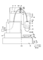
- FIG. 3 is a schematic diagram of the stacking head according to this embodiment.
- the laminated head 18 has an inner tube 42 and an outer tube 44.
- the outer tube 44 is a tubular member, and its diameter decreases toward the tip, that is, the direction Z2.
- the inner tube 42 is also a tubular member, and its diameter decreases toward the tip, that is, the direction Z2. Since the inner pipe 42 is inserted inside the outer pipe 44, the inner pipe 42 and the outer pipe 44 form a double pipe.
- the space on the inner peripheral surface side of the inner tube 42 serves as a beam path 42A through which the light beam L passes.
- the space between the outer peripheral surface of the inner tube 42 and the inner peripheral surface of the outer tube 44 serves as a powder passage 44A through which the powder P passes. That is, the powder flow path 44A is a flow path having a shape that surrounds the beam path 42A. In the present embodiment, the powder flow path 44A is concentrically arranged on the outer circumference of the beam path 42A.
- the laminated head 18 has a light beam irradiation port 42B open at the end 40A on the direction Z2 side.
- the laminating head 18 is provided with the fiber connection port 48 at the end 40B on the direction Z1 side, that is, the end opposite to the end 40A.
- the fiber connection port 48 is an opening provided in the end portion 40B.
- the light beam irradiation port 42B and the fiber connection port 48 communicate with each other via the beam path 42A. That is, the light beam irradiation port 42B is an opening on the beam path 42A side in the direction Z2, and the fiber connection port 48 is an opening on the beam path 42A in the direction Z1 side.
- the laminated head 18 is provided with an optical element 46 at a position between the light beam irradiation port 42B and the fiber connection port 48 of the beam path 42A.
- the optical element 46 includes, for example, a collimator lens that collimates the light beam L and a condenser lens that condenses the collimated light beam L.
- the configuration of the optical element 46 is not limited to this, and is arbitrary.
- the fiber 24 is connected to the fiber connection port 48.
- the fiber 24 is a fiber that is connected to the light source unit 33 that serves as the light source of the light beam L, and the end 24A is connected to the fiber connection port 48.
- the fiber 24 receives the light beam L from the light source unit 33, guides the incident light beam L to the end portion 24A, and emits the light beam L from the end portion 24A into the beam path 42A of the stacking head 18.
- the light beam L emitted into the beam path 42A travels in the beam path 42A in the direction Z2, passes through the optical element 46, and is emitted from the light beam irradiation port 42B to the outside of the stacking head 18.
- the light beam L emitted from the light beam irradiation port 42B advances in the direction Z2 and is irradiated toward the base portion 14.
- the powder injection port 44B is opened at the end 40A on the Z2 side.
- the powder injection port 44B opens so as to surround the light beam irradiation port 42B.
- the laminated head 18 is provided with a pipe connection port 49 at the end 40B on the direction Z1 side.
- the pipe connection port 49 is an opening provided in the end portion 40B.
- the powder injection port 44B and the pipe connection port 49 communicate with each other via the powder flow path 44A. That is, the powder injection port 44B is an opening on the direction Z2 side of the powder flow path 44A, and the pipe connection port 49 is an opening on the direction Z1 side of the powder flow path 44A.
- the pipe 26 is connected to the pipe connection port 49.
- the pipe 26 is a pipe connected to the powder supply unit 34, which is a tank in which the powder P is stored, and the end portion 26A is connected to the pipe connection port 49.
- the pipe 26 guides the powder P from the powder supply unit 34 to the end portion 26A, and supplies the powder P from the end portion 26A into the powder flow path 44A of the stacking head 18.
- the powder P supplied into the powder flow path 44A flows in the powder flow path 44A in the direction Z2 and is jetted from the powder jet port 44B to the outside of the laminating head 18.
- the powder P injected from the powder injection port 44B advances in the direction Z2 and is injected toward the base portion 14.
- the light beam L is irradiated toward the base portion 14 with a predetermined spot diameter.
- the light beam L is applied to the base material A on the base portion 14 so that the spot diameter, that is, the convergence position of the light beam overlaps.
- the base material A may be a laminate that is being laminated in the three-dimensional laminating apparatus 1 or may be a member that is a base material of the laminate.
- the base material A is melted by the light beam L to form a molten pool A1 in which the base material A is melted.
- the powder P is injected toward the base portion 14 with a predetermined convergence diameter.
- the powder P is injected toward the melting pool A1, that is, so that the convergence position overlaps with the melting pool A1.
- the powder P injected from the powder injection port 44B is melted in the melting pool A1. Then, since the base portion 14 moves with respect to the stacking head 18, the position where the light beam L is irradiated changes. Therefore, the part where the molten pool A1 was formed by being irradiated with the light beam L is cooled and solidified by being not irradiated with the light beam L to form the bead A2. By laminating the beads A2 in a three-dimensional manner, a laminated body is formed.
- the light beam L in this embodiment is a laser beam, but it is not limited to a laser beam and may be, for example, an electron beam.
- the powder P in the present embodiment is a metal powder, but if it is a powder, it is not limited to the metal powder.
- the fiber 24 for transmitting the light beam L and the tube 26 for supplying the powder P are connected to the laminating head 18, but other tubes are connected to the laminating head 18. It may be connected.
- a pipe that supplies gas to the stacking head 18 or a pipe that supplies cooling water to the stacking head 18 may be connected to the stacking head 18.
- These tubes are also preferably connected to the end 40B of the laminating head 18.
- the gas supplied by the tube connected to the stacking head 18 covers the gas for supplying the powder P to the powder flow path 44A and the periphery of the part to which the powder P and the light beam L are supplied. An inert gas supplied in this manner is included.
- the rotating mechanism 20 is a mechanism that is connected to the stacking head 18 and rotates the stacking head 18 about a rotation axis that intersects the direction Z.
- the rotation mechanism 20 is attached to the base portion 16 via the head moving portion 22, it may be attached to the base portion 16 without passing through the head moving portion 22, or it may not be attached to the base portion 16. Good. That is, the mounting position of the rotating mechanism 20 is arbitrary.
- the rotating mechanism 20 has a first plate portion 50, a second plate portion 52, and a connecting portion 54.
- the first plate portion 50 is a plate-shaped member.
- the back surface 50B of the first plate portion 50 which is the surface opposite to the front surface 50A, is attached to the base portion 16 via the head moving portion 22.
- the surface 52A of the second plate portion 52 is rotatably attached to the surface 50A of the first plate portion 50.
- the connecting portion 54 is a member that connects the second plate portion 52 and the laminated head 18.
- connection portion 54 connects, for example, the back surface 52B, which is the surface opposite to the surface 52A of the second plate portion 52, and the side surface of the stacking head 18 (here, the surface on the direction X side).
- the connecting portion 54 connects the second plate portion 52 and the laminated head 18 so that their relative positions are fixed to each other. That is, the position of the stacking head 18 is fixed with respect to the second plate portion 52.
- the detailed structure of the rotating mechanism 20 will be described later.
- the head moving portion 22 moves the laminated head 18 along the direction Z.
- the head moving unit 22 is attached to the base unit 16.
- the head moving unit 22 moves the rotation mechanism 20 and the laminated head 18 connected to the rotation mechanism 20 along the direction Z.
- the head moving unit 22 is a slider that moves the rotating mechanism 20 and the laminated head 18, but may be a mechanism other than the slider.
- the head moving portion 22 is not limited to being mounted on the base portion 16, and the mounting position is arbitrary.
- the pulley portion 28 is provided on the direction Z1 side of the stacking head 18 and movably sandwiches the fiber 24.
- the pulley portion 28 has a pulley 28A and a pulley 28B.
- the pulley 28A and the pulley 28B are shaft-shaped members.
- the pulley 28A extends along the direction X from the base 16 toward the side where the stacking head 18 is provided, and rotates about the axis along the direction X.
- the pulley 28B is provided on the direction Z2 side of the pulley 28A.
- the pulley 28B extends along the direction X from the base 16 toward the side where the stacking head 18 is provided, and rotates about an axis along the direction X.
- the pulley 28A and the pulley 28B are provided in the slide portion 28C, and move in the slide portion 28C along the direction Z.
- the pulley 28A and the pulley 28B are connected to the rotation mechanism 20, and move along the direction Z integrally with the rotation mechanism 20 and the stacking head 18.
- a fiber 24 is provided between the pulley 28A and the pulley 28B.
- the intermediate portion 24C between the end portion 24A connected to the fiber connection port 48 of the laminating head 18 and the end portion 24B connected to the light source portion 33 has a pulley. It is located between 28A and 28B pulley. That is, the fiber 24 is sandwiched between the pulley 28A and the pulley 28B in the intermediate portion 24C. Since the pulley 28A and the pulley 28B rotate, the fiber 24 is movable with respect to the pulley 28A and the pulley 28B.
- the pipe 26 is also movably sandwiched by the pulley portion 28 like the fiber 24.
- the fiber 24 and the tube 26 are sandwiched by the pulley unit 28 so as not to contact each other via a partition unit 28A1 provided on the pulley 28A.
- the pipe, like the fiber 24 be movably held by the pulley portion 28.
- the pulley portion 28 has a structure in which the fiber 24 and the pipe 26 can be removed. As shown in FIG. 1, the pulley 28A rotates in the direction Y around the portion 28A2 on the base 16 side. As a result, the pulley 28A opens as shown by the broken line in FIG. 1 to form a space in which the fiber 24 and the pipe 26 can be attached and detached.
- the base portion 30 is a base on which the cover portion 32 is provided on the upper surface.
- the cover portion 32 is a cover that covers the fiber 24.
- the cover portion 32 is arranged on the direction Y1 side of the stacking head 18, that is, on the back side of the three-dimensional stacking device 1 with respect to the stacking head 18.
- the surface 32A of the cover portion 32 is arranged so as to face the stacking head 18 in the direction Y. It can be said that the surface 32A of the cover portion 32 is provided between the fiber 24 and the laminated head 18 in the direction Y.
- the cover portion 32 has an opening on the Z1 side of the laminating head 18, and the fiber 24 is inserted into the cover portion 32 from the opening on the Z1 side, that is, on the Y1 side of the surface 32A.
- the cover portion 32 covers the tube 26 in addition to the fiber 24.
- the tube is preferably covered with the cover portion 32, similarly to the fiber 24.
- the cover part 32 suppresses the heat due to the light beam L or the like at the time of stacking from being transmitted to the fiber 24.
- the cover portion 32 is configured to be removable from the three-dimensional laminating device 1.
- the control unit 36 shown in FIG. 1 is a control device for controlling the three-dimensional laminating apparatus 1, here a numerical control device.
- the control unit 36 controls the base moving unit 12 to move the base unit 14, controls the head moving unit 22 to move the laminated head 18 along the direction Z, and causes the light beam L by the laminated head 18 to move. Irradiation is controlled to control the injection of powder P by the stacking head 18.
- the rotation mechanism 20 is, for example, a mechanism that rotates by human power, and is not a mechanism that automatically rotates under the control of the control unit 36. However, the rotation mechanism 20 may be rotated under the control of the control unit 36.
- FIG. 4 is a schematic view of the first plate portion.
- the first plate portion 50 of the rotating mechanism 20 has a front surface 50A and a back surface 50B along the direction Z.
- the surface of the first plate portion 50 is wider on the direction Y2 side than on the direction Y1 side, but such a shape is an example.
- the first plate portion 50 is provided with a rotary bearing portion 60, openings 62 and 64, and a protrusion 66.
- the rotary bearing portion 60 constitutes the rotary shaft portion 20a of the rotary mechanism 20 together with the shaft portion 70 of the second plate portion 52 described later.
- the rotary bearing portion 60 has an opening 60A and a bearing portion 60B.
- the opening 60A is a hole that opens to the surface 50A.
- the opening 60A is provided so that the central axis is orthogonal to the surface 50A, and here, the central axis is along the direction X.
- the bearing portion 60B is a bearing that is inserted into the opening portion 60A.
- the bearing portion 60B is, for example, a rolling bearing, a sliding bearing, or the like.
- the openings 62 and 64 are holes penetrating from the front surface 50A to the back surface 50B.
- the protrusion 66 is a protrusion that protrudes from the surface 50A.
- the protruding portion 66 constitutes a positioning portion 20c1 of the rotating mechanism 20 together with a cutout portion 76 of the second plate portion 52 which will be described later.
- the positions where the rotary bearing portion 60, the openings 62 and 64, and the protrusion 66 are provided are not limited to the example of FIG.
- FIG. 5 is a schematic view of the second plate portion.
- FIG. 5 shows the second plate portion 52 in the orientation of the first state.
- the front surface 52A and the back surface 52B are along the direction Z.
- the second plate portion 52 is provided with a shaft portion 70, openings 72 and 74, and a cutout portion 76.
- the shaft portion 70 is a shaft-shaped member protruding from the surface 52A along the direction X.
- the openings 72 and 74 are holes penetrating from the front surface 52A to the back surface 52B.
- the notch portion 76 is a notch provided on the side surface of the second plate portion 52.
- the second plate portion 52 may have a grip portion 78 on the side surface.
- the grip portion 78 is a member for the operator to grip. The operator can rotate the second plate portion 52 by gripping the grip portion 78 and applying a moment in the rotation direction to the second plate portion 52.
- the surface 50A of the first plate portion 50 and the surface 52A of the second plate portion 52 are along the direction Z, but are not limited to being along the direction Z.
- the surface 50A of the first plate portion 50 and the surface 52A of the second plate portion 52 need not be orthogonal to the direction Z.
- the surface 50A of the first plate portion 50 and the surface 52A of the second plate portion 52 may intersect with each other with respect to a plane orthogonal to the direction Z.
- the second plate portion 52 is rotatably connected to the first plate portion 50. More specifically, as shown in FIG. 1, the second plate portion 52 is connected to the first plate portion 50 such that the surface 52A contacts the surface 50A of the first plate portion 50. Then, the second plate portion 52 is connected to the laminating head 18 on the back surface 50B opposite to the surface 50A with which the first plate portion 50 contacts.
- the configuration in which the second plate portion 52 is connected to the first plate portion 50 will be described.
- FIG. 6 and 7 are schematic views of the rotation mechanism according to the present embodiment.
- FIG. 6 shows the first state
- FIG. 7 shows the second state.
- the first state is a state in which the fiber connection port 48 of the laminating head 18 attached to the second plate portion 52 faces the direction Z1 side and opens. Further, in the first state, the direction from the center of the laminating head 18 toward the fiber connection port 48 may be said to be along the direction Z1.
- the central axis of the fiber connection port 48 is the central axis AX2
- the first state is a state in which the fiber connection port 48 is open toward the direction Z1 side and the central axis AX2 is along the direction Z1. You can say that. Further, the first state can be said to be a state in which the light beam irradiation port 42B and the powder injection port 44B of the stacking head 18 are opened facing the direction Z2.
- the first plate portion 50 and the second plate portion 52 are connected so that the rotary bearing portion 60 of the first plate portion 50 and the shaft portion 70 of the second plate portion 52 overlap each other. More specifically, the surface 52A of the second plate portion 52 is in contact with the surface 50A of the first plate portion 50, and the shaft portion 70 provided on the surface 52A is inserted into the rotary bearing portion 60.
- the shaft portion 70 is rotatable in a state of being inserted into the rotary bearing portion 60. That is, since the shaft portion 70 serves as the rotation shaft of the second plate portion 52, it can be said that the rotation bearing portion 60 and the shaft portion 70 form the rotation shaft portion 20a.
- the rotary shaft portion 20a in the present embodiment is a mechanism in which the shaft portion 70 rotates in the rotary bearing portion 60, but as long as it is a rotatable mechanism, it is limited to such a structure of the shaft and the bearing. I can't.
- the opening 62 of the first plate portion 50 and the opening 72 of the second plate portion 52 overlap each other when viewed from the direction X.
- a member such as a bolt is inserted into the opening 62 and the opening 72 so that the first plate 50 and the second plate 52 are overlapped with each other. Fix with.
- the first plate portion 50 and the second plate portion 52 are fixed in a state in which the opening 62 and the opening 72 are overlapped, that is, in the first state.
- the opening 62 and the opening 72 serve as the fixing portion 20b1 that fixes the first plate 50 and the second plate 52 in the first state.
- the fixing portion 20b1 fixed in the first state is not limited to the opening 62 and the opening 72, and may have another configuration.
- the notch 76 of the second plate 52 and the protrusion 66 of the first plate 50 are overlapped with each other in a state where the protrusion 66 is located in the notch 76. It is provided at such a position.
- the cutout portion 76 and the projection portion 66 are provided at positions where the projection portion 66 is located in the cutout portion 76 and is in the first state. Therefore, for example, when changing from the second state to the first state, the second plate portion 52 is rotated until the protruding portion 66 is located in the cutout portion 76, and in that state the opening portion 62 and the opening portion 62 are opened. By inserting a bolt into the 72, the first plate portion 50 and the second plate portion 52 are fixed in the first state.
- the notch portion 76 and the protrusion portion 66 serve as the positioning portion 20c1 that defines the first plate portion 50 and the second plate portion 52 in the position of the first state.
- the positioning portion 20c1 that defines the position in the first state is not limited to the cutout portion 76 and the protruding portion 66, and may have another configuration.
- the second state is a state in which the fiber connection port 48 of the laminating head 18 attached to the second plate portion 52 is opened in a direction intersecting the direction Z1. Further, the second state may be said to be a state in which the direction from the center of the laminating head 18 toward the fiber connection port 48 intersects the direction Z1. Moreover, it may be said that the second state is a state in which the central axis AX2 is along the direction intersecting the direction Z1.
- the angle formed by the virtual axis AX and the central axis AX2 along the direction Z1 is referred to as an angle ⁇ .
- the angle ⁇ is preferably 85 degrees or more and 95 degrees or less.
- the angle ⁇ is 90 degrees, that is, the central axis AX2 is along the horizontal direction orthogonal to the direction Z1.
- the light beam irradiation port 42B and the powder injection port 44B of the stacking head 18 are also opened in a direction intersecting the direction Z1 side.
- the maximum rotation angle of the rotation mechanism 20 is larger than the angle formed by the central axis AX2 of the stacking head 18 with respect to the vertical direction at the time of molding the laminated body A.
- the second state is a state after the second plate portion 52 has rotated about the rotary shaft portion 20a (the shaft portion 70 and the rotary bearing portion 60) from the first state.
- the opening 64 of the first plate portion 50 and the opening 74 of the second plate portion 52 overlap each other when viewed from the direction X.
- a member such as a bolt is inserted into the opening 64 and the opening 74, and the first plate portion 50 and the second plate portion 52 are superposed on the opening 64 and the opening 74. Fix with. As a result, the first plate portion 50 and the second plate portion 52 are fixed in a state in which the opening 64 and the opening 74 are overlapped, that is, in the second state. As described above, the opening 64 and the opening 74 are fixed portions 20b2 for fixing the first plate portion 50 and the second plate portion 52 in the second state.
- the fixing portion 20b2 fixed in the second state is not limited to the opening 64 and the opening 74, and may have another configuration.
- the side surface 52C of the second plate portion 52 and the protruding portion 66 of the first plate portion 50 are positioned such that the opening portion 64 and the opening portion 74 overlap with each other while the side surface 52C and the protruding portion 66 are in contact with each other.
- the side surface 52C and the protrusion 66 are provided at positions such that the side surface 52C and the protrusion 66 are in the second state when they are in contact with each other. Therefore, for example, when changing from the first state to the second state, the second plate portion 52 is rotated until the side surface 52C and the protrusion portion 66 come into contact with each other, and in that state, the opening 64 and the opening 74 are formed.
- the first plate portion 50 and the second plate portion 52 are fixed in the second state by inserting a bolt into the.
- the side surface 52C and the protrusion 66 serve as the positioning portion 20c2 that defines the first plate portion 50 and the second plate portion 52 at the position in the second state.
- the positioning portion 20c2 defined at the position of the second state is not limited to the side surface 52C and the protrusion 66, and may have a different configuration.
- the rotation mechanism 20 is in the above state in the first state and the second state.
- the second plate portion 52 is rotated around the rotation shaft AX1 which is the central axis of the rotation shaft portion 20a. Since the position of the stacking head 18 is fixed with respect to the second plate portion 52, the stacking head 18 rotates integrally with the second plate portion 52, and the first state and the second state are switched.
- the bolts are removed from the opening 62 and the opening 72 to release the fixing in the first state, and then the second plate portion 52 is moved. , Rotate around the rotation axis AX1 (counterclockwise in the examples of FIGS. 6 and 7).
- the bolts are fixed in the second state.
- the bolts are removed from the opening 64 and the opening 74 to release the fixing in the second state, and then the second plate portion 52 Is rotated around the rotation axis AX1 (clockwise in the examples of FIGS. 6 and 7).
- the bolts are fixed in the first state.
- the three-dimensional laminating apparatus 1 removes the fiber 24 conducting the light beam L from the laminating head 18 at the time of maintenance or the like.
- the fiber connection port 48 of the stacking head 18 is exposed, and foreign matter such as dust may enter the stacking head 18 through the fiber connection port 48.
- the fiber connection port 48 is open toward the direction Z1 side, that is, toward the upper side in the vertical direction, the possibility that foreign matter may enter due to gravity or the like increases. Therefore, it is preferable that the fiber connection port 48 be opened in a direction intersecting from the vertically upper side, for example, in the horizontal direction orthogonal to the vertical direction.
- the laminated body is laminated in a state where the light beam irradiation port 42B and the powder ejection port 44B are opened facing the direction Z2 side, that is, the lower side in the vertical direction. Therefore, in the three-dimensional stacking device 1, it is preferable that the fiber connection port 48 intersects the upper part in the vertical direction and the light beam irradiation port 42B faces the lower part in the vertical direction.
- the light beam irradiation port 42B is arranged on the bottom surface (the surface on the lower side in the vertical direction) of the stacking head 18, and the fiber connection port 48 is arranged on the side surface (the surface on the horizontal direction side) of the stacking head 18. It is also possible to do it. However, in this case, in order to guide the light beam L incident from the fiber connection port 48 on the side surface to the light beam irradiation port 42B on the bottom surface, it is necessary to take measures such as bending the optical path of the light beam L. There may be a need to increase the number. In this case, the device size becomes large.
- the light beam irradiation port 42B is provided on the side surface, that is, the light beam L or the powder P is laterally supplied, for example, and then the lamination conditions are devised so that the lamination is appropriately performed. ..
- the fiber connection port 48 is provided on the side surface opposite to the light beam irradiation port 42B.
- the laminated head 18 since the laminated head 18 becomes long in the horizontal direction, the laminated head 18 may interfere with the cover portion 32 horizontally adjacent to the laminated head 18.
- the rotation mechanism 20 is used to direct the fiber connection port 48 upward in the vertical direction and the fiber connection port 48 in the direction intersecting the vertical direction.
- the second state can be switched. Therefore, at the time of maintenance, by switching to the second state and then removing the fiber 24, the light beam irradiation port 42B can be opened in a direction intersecting from above in the vertical direction, and contamination of foreign matter can be suppressed. Further, for example, by designing the light beam irradiation port 42B so as to face downward in the vertical direction in the first state, it is possible to appropriately perform stacking in the first state and suppress an increase in device size. ..
- the three-dimensional laminating apparatus 1 by switching between the first state and the second state, it is possible to suppress the mixture of foreign matters and suppress an increase in the size of the apparatus. .. Further, the cover portion 32 suppresses the transfer of heat during lamination to the fibers 24 and the like.
- the three-dimensional laminating apparatus 1 can prevent the laminating head 18 from interfering with the cover portion 32 at the time of laminating by setting the first state when laminating the cover portion 32. Further, in the second state, since the laminating head 18 is in the horizontal direction and may interfere with the cover portion 32, the cover portion 32 can be removed because the temperature does not rise during maintenance in the second state. That is, by removing the cover portion 32 before the second state, the interference of the cover portion 32 can be prevented.
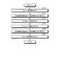
- FIG. 8 is a flowchart illustrating the flow of the fiber replacement method.
- FIG. 8 shows a flow of replacing the fiber 24 from the state in which the fiber 24 is connected to the laminated head 18 in the first state.
- the cover portion 32 is removed from the three-dimensional stacking device 1 in a state where the driving of the stacking head 18 (supply of powder P and light beam L) is stopped (step S10). ).
- the second plate portion 52 is switched to the second state (step S12; first rotation step).
- the laminated head 18 is in a state of opening in the direction in which the fiber connection port 48 intersects the downward direction in the vertical direction. It is preferable to remove the fiber 24 (and the pipe 26) from the pulley portion 28 before rotating the second plate portion 52. However, the second plate is left with the fiber 24 (and the pipe 26) attached to the pulley portion 28. The part 52 may be rotated.
- the fiber 24 is removed from the fiber connection port 48 of the laminated head 18 (step S14; removal step), maintenance and the like are completed, and the fiber 24 is held in the second state until it is reattached.
- the fiber 24 is attached to the fiber connection port 48 of the laminating head 18 in the second state (step S16; attachment step).
- the fiber 24 to be attached may be different from the removed fiber 24, or may be the same. For example, when changing the shape of the beam, the fiber is changed to another fiber.
- the second plate portion 52 is rotated with respect to the first plate portion 50 to switch from the second state to the first state (step S18; second rotation step), and the cover portion 32 is attached again. (Step S20), the present process ends. It should be noted that the attachment and detachment of the cover portion 32 is not essential.
- the three-dimensional laminating device 1 has a laminating head 18 and a rotating mechanism 20.
- the laminating head 18 is provided with a powder ejection port 44B for ejecting the powder P, a light beam irradiation port 42B for irradiating the light beam L, and a fiber connection port 48 to which the fiber 24 for guiding the light beam L is connected.
- the rotating mechanism 20 is connected to the stacking head 18 and rotates the stacking head 18 about a rotation axis AX1 intersecting the vertical direction.
- the rotating mechanism 20 rotates the stacking head 18 to open the fiber connection port 48 in the first direction in which the fiber connection port 48 faces the direction Z1 (vertical direction upper side) and the fiber connection port 48 moves in the direction Z1 (vertical direction upper direction).
- the second state which opens in the direction of intersection with respect to the side, is switched.
- the three-dimensional stacking device 1 has a first state in which the fiber connection port 48 is directed upward in the vertical direction and a second state in which the fiber connection port 48 is directed in the vertical direction by the rotation mechanism 20. You can switch between and. Therefore, by removing the fiber 24 after switching to the second state, it is possible to switch to the first state while suppressing the mixture of foreign matter, and thus it is possible to prevent the device size from increasing.
- the fiber connection port 48 is opened in a direction intersecting with the direction Z (vertical direction) by 85 degrees or more and 95 degrees or less.
- the orientation of the fiber connection port 48 can be made closer to the horizontal direction, and the mixture of foreign matter can be suppressed.
- the fiber connection port 48 by not pointing the fiber connection port 48 downward in the vertical direction, it is possible to prevent the fiber 24 from facing upward in the vertical direction when the fiber 24 is attached, and to prevent foreign matter from entering the fiber 24 side. You can
- the three-dimensional laminating apparatus 1 includes a head moving unit 22 that moves the laminating head 18 along the direction Z, a base unit 14 onto which the powder P is ejected from the laminating head 18 and the light beam L is irradiated, and a base. It is preferable to have the platform moving unit 12.
- the base moving unit 12 moves the base unit 14 along a first direction orthogonal to the vertical direction and a second direction orthogonal to the vertical direction and the first direction.
- the three-dimensional stacking device 1 has a configuration in which the stacking head 18 moves along one axis along the direction Z.
- the laminating head 18 may be configured to move along multiple axes, or may be configured to rotate about a predetermined rotation axis (for example, three rotation axes).
- the rotating shaft AX1 of the rotating mechanism 20 is preferably a rotating shaft different from the rotating shaft about which the stacking head 18 rotates (the rotating directions may be the same). That is, it is preferable that the rotating shaft AX1 of the rotating mechanism 20 is a rotating shaft different from the rotating shaft used when laminating is performed by the laminating head 18, and further, the rotating mechanism 20 is laminated by the laminating head 18. It is preferable that the mechanism is different from the rotation mechanism used when performing the above.
- the rotation mechanism (rotation shaft) used when laminating with the stacking head 18 is shared with the rotation mechanism 20 (rotation shaft AX1), the rotation mechanism (rotation) used when laminating with the stacking head 18 is used. It is necessary to realize a rotation angle with respect to the shaft) so as to preferably suppress foreign matter contamination. In this case, the rotation mechanism used for laminating needs to realize a large rotation angle of, for example, 85 degrees or more and 95 degrees or less with respect to the vertical direction. However, when the rotating mechanism used for stacking has such a large rotation angle, the stacking head structure may be complicated and lengthened, and the stacking accuracy may be affected.
- the fiber connection port 48 is provided on the surface (end 40B) opposite to the surface (end 40A) where the powder injection port 44B and the light beam irradiation port 42B are provided in the laminated head 18.
- the fiber connection port 48 is arranged on the side surface (the surface on the horizontal direction side) of the stacking head 18, the light beam L incident from the fiber connection port 48 on the side surface is guided to the light beam irradiation port 42B on the bottom surface.
- the optical path becomes complicated, such as bending the optical path of the beam L, and the size of the device may increase.
- the fiber connection port 48 on the opposite surface of the light beam irradiation port 42B and the powder injection port 44B, it is possible to simplify the optical path of the light beam L and prevent the device size from increasing. it can.
- the rotation mechanism 20 includes a first plate portion 50 and a second plate portion 52.
- the first plate portion 50 intersects a plane whose surface 50A is orthogonal to the vertical direction.
- the second plate portion 52 is fixed to the laminating head 18, and is rotatably connected to the first plate portion 50 with the surface 52A in contact with the surface 50A of the first plate portion 50.
- the rotation mechanism 20 switches between the first state and the second state by rotating the second plate portion 52 with respect to the first plate portion 50.
- the three-dimensional laminating apparatus 1 includes the first plate portion 50 and the second plate portion 52 as the rotating mechanism 20, so that the first state and the second state can be appropriately switched. Furthermore, by bringing the surfaces of the first plate portion 50 and the second plate portion 52 into contact with each other, the misalignment of the stacking head 18 can be suitably suppressed.
- the rotation mechanism 20 includes a rotation shaft portion 20a that serves as a rotation shaft of the second plate portion 52 with respect to the first plate portion 50, a positioning portion 20c2 that positions the second plate portion 52 in the second state, and a second plate portion. And a fixing portion 20b2 that fixes 52 in the second state.
- the second plate portion 52 can be rotated about the rotary shaft portion 20a, and can be fixed in the second state by the fixing portion 20b2 while being positioned by the positioning portion 20c2. It is possible to switch appropriately between the two states.
- the three-dimensional laminating device 1 further has a removable cover portion 32 that covers the fiber 24.
- the cover portion 32 suppresses the transfer of heat during lamination to the fibers 24 and the like.
- the cover portion 32 does not interfere with the laminated head 18 in the first state, but interferes with the laminated head 18 in the second state.
- the cover portion 32 does not interfere with the laminating head 18 in the first state in which lamination is performed, and the cover portion 32 can be removed in the second state in which the cover portion 32 is unnecessary. Even when there is 32, it is possible to appropriately switch between the first state and the second state to suppress the mixing of foreign matter.
- the cover portion 32 may not interfere with the laminated head 18 even in the second state.
- the three-dimensional laminating device 1 is provided on the direction Z1 side of the laminating head 18, and further has a pulley portion 28 that movably sandwiches the fiber 24.
- the three-dimensional laminating apparatus 1 can appropriately hold the fiber 24 by sandwiching the fiber 24 with the pulley portion 28.
- the method for replacing the fiber 24 is configured such that the laminated head 18 is rotated from the first state to the second state by rotating the laminated head 18 about the rotation axis AX1 intersecting the vertical direction.
- One rotation step a removal step of removing the fiber 24 from the fiber connection port 48 of the lamination head 18 in the second state, and a fiber 24 or a fiber connection port 48 of the lamination head 18 from which the fiber 24 has been removed by the removal step.
- this replacement method it is possible to switch to the second state and then to remove the fiber 24, thereby suppressing foreign matter from entering and switching to the first state, thereby suppressing an increase in the device size. be able to.
- the rotation mechanism 20 has a configuration in which the second plate portion 52 rotates about the rotation shaft portion 20a with respect to the first plate portion 50
- the configuration of the rotation mechanism 20 is not limited to this.
- I can't. 9 and 10 are schematic views showing another example of the rotation mechanism according to the present embodiment.
- the first plate portion 50 of the rotation mechanism 20 has a groove portion 60a.
- the groove portion 60a is a groove provided on the surface 50A of the first plate portion 50, and has an arc shape with the rotation axis AX1 as the center.
- the shaft portion 70a of the second plate portion 52 is movably inserted into the groove portion 60a. In the first state of FIG.
- the shaft portion 70a is located on one end side of the groove portion 60a. Then, by moving the shaft portion 70a along the groove portion 60a, the second plate portion 52 rotates about the rotation axis AX1 as a center axis, and the shaft portion 70a is positioned on the other end side of the groove portion 60a. It becomes a state. In this way, the rotation mechanism 20 may provide the groove portion 60a to rotate the second plate portion 52.
- the rotating mechanism 20 does not have to have the configuration including the first plate portion 50 and the second plate portion 52 as long as it rotates the stacking head 18 to switch between the first state and the second state.
- the rotation mechanism 20 may be a mechanism that includes a shaft and a coupling and that rotates the stacking head 18 using a motor as a drive source.
- the rotation mechanism 20 may include a crank mechanism and a cylinder, and by driving the cylinder, It may be a mechanism for rotating the laminating head 18.
- the drive source of the cylinder in this case is arbitrary, and may be, for example, air, electric, or manual.
- the rotation mechanism 20 may be a mechanism for rotating the laminated head 18 by a circular rail.
- a key may be provided as the positioning portion, or a part of the outer circumference may be a flat surface and the other part may be a circumferential shape.
- the rotation mechanism 20 may be a mechanism for rotating the laminated head 18 by a planetary gear. Further, a gear may be used as the speed reducer, and a mechanism for reducing the force required for rotation may be added.
- the embodiments of the present invention have been described above, the embodiments are not limited by the contents of the embodiments. Further, the components described above include those that can be easily assumed by those skilled in the art, those that are substantially the same, and those within the so-called equivalent range. Furthermore, the components described above can be combined appropriately. Furthermore, various omissions, replacements, or changes of the constituent elements can be made without departing from the scope of the above-described embodiment.
Landscapes
- Engineering & Computer Science (AREA)
- Physics & Mathematics (AREA)
- Optics & Photonics (AREA)
- Mechanical Engineering (AREA)
- Manufacturing & Machinery (AREA)
- Materials Engineering (AREA)
- Chemical & Material Sciences (AREA)
- Plasma & Fusion (AREA)
- Health & Medical Sciences (AREA)
- General Health & Medical Sciences (AREA)
- Toxicology (AREA)
- Laser Beam Processing (AREA)
- Powder Metallurgy (AREA)
Abstract
三次元積層装置(1)は、粉末噴射口(44B)、光ビーム照射口(42B)、及び、ファイバー(24)が接続されるファイバー接続口(48)が設けられる積層ヘッド(18)と、積層ヘッド(18)を鉛直方向に沿って移動させるヘッド移動部(22)と、積層ヘッド(18)から粉末Pが噴射されて光ビーム(L)が照射される基台部(14)と、基台部(14)を第1方向と第2方向とに沿って移動させる基台移動部(12)と、積層ヘッド(18)に接続され、鉛直方向に交差する回転軸を中心として積層ヘッド(18)を回転させる回転機構(20)と、を備える。回転機構(20)は、積層ヘッド(18)を回転させることで、ファイバー接続口(48)が、鉛直方向上方側を向いて開口する第1状態と、ファイバー接続口(48)が、鉛直方向上方側に対して交差する方向を向いて開口する第2状態と、を切り替える。
Description
本発明は、三次元積層装置及びファイバーの取替方法に関する。
近年、金属粉末などの粉末を原料として三次元積層体を成形する積層体成形方法が実用化されている。例えば特許文献1には、積層ヘッドから光ビームを照射しつつ粉末を噴射することで三次元積層体を製造する、デポジション方式の三次元積層装置が記載されている。特許文献1のようなデポジション方式においては、一般的に、光ビームを導くためのファイバーが積層ヘッドに接続されている。
積層ヘッドに接続されるファイバーは、メンテナンス時などにおいては、積層ヘッドから取り外される。しかし、取り外された際に、ファイバーと接続されていた箇所から積層ヘッド内に、ほこりなどの異物が混入するおそれがある。異物が混入すると、光ビームが異物に照射されるなどの原因により、積層ヘッド、ファイバー、積層ヘッドに接続される光源などが破損する可能性がある。従って、積層ヘッドにおいては、異物の侵入を抑制するように、ファイバーが接続される位置を設定することが求められる。さらに、ファイバーが接続される位置、すなわち光ビームの入射位置と、光ビームの出射位置との関係によっては、積層ヘッド内の光学部品の数を多くする必要が生じて、装置サイズが大きくなってしまうおそれもある。従って、装置サイズが大きくなることを抑制しつつ、メンテナンス時に異物の混入を抑制する三次元積層装置が求められている。
本発明は、上述した課題を解決するものであり、装置サイズが大きくなることを抑制しつつ、メンテナンス時に異物の混入を抑制する三次元積層装置及びファイバーの取替方法を提供することを目的とする。
上述した課題を解決し、目的を達成するために、本開示に係る三次元積層装置は、粉末を噴射する粉末噴射口、光ビームを照射する光ビーム照射口、及び、前記光ビームを導くファイバーが接続されるファイバー接続口が設けられる積層ヘッドと、前記積層ヘッドを鉛直方向に沿って移動させるヘッド移動部と、前記積層ヘッドから、前記粉末が噴射されて前記光ビームが照射される基台部と、前記基台部を、前記鉛直方向に直交する第1方向と、前記鉛直方向及び前記第1方向に直交する第2方向とに沿って移動させる基台移動部と、前記積層ヘッドに接続され、鉛直方向に交差する回転軸を中心として前記積層ヘッドを回転させる回転機構と、を備え、前記回転機構は、前記積層ヘッドを回転させることで、前記ファイバー接続口が、鉛直方向上方側を向いて開口する第1状態と、前記ファイバー接続口が、鉛直方向上方側に対して交差する方向を向いて開口する第2状態と、を切り替える。
この三次元積層装置は、第2状態に切り替えてからファイバーを取り外すことにより、異物の混入を抑制しつつ、第1状態にも切り替え可能とすることで、装置サイズが大きくなることを抑制することができる。
前記回転機構の最大回転角度は、前記積層体の成形時において前記積層ヘッドの中心軸が鉛直方向に対してなす角度よりも大きいことが好ましい。この三次元積層装置によると、ファイバー接続口の向きを水平方向に近づけて、異物の混入を抑制できる。
前記ファイバー接続口は、前記第2状態において、鉛直方向に対して、85度以上95度以下交差する方向に向いて開口することが好ましい。この三次元積層装置は、ファイバー接続口の向きを水平方向に近づけて、異物の混入を抑制できる。
前記ファイバー接続口は、前記積層ヘッドにおいて前記光ビーム照射口が設けられる面と反対側の面に設けられることが好ましい。この三次元積層装置は、光ビーム照射口と粉末噴射口とを反対の面に設けることで、光ビームの光路を簡易にすることができ、装置サイズが大きくなることを抑制できる。
前記回転機構は、表面が鉛直方向に直交する平面に交差する第1板部と、前記積層ヘッドに固定され、前記第1板部の表面に表面が接触した状態で前記第1板部に対して回転可能に接続される第2板部と、を備え、前記第2板部が前記第1板部に対して回転することで、前記第1状態と前記第2状態とを切り替えることが好ましい。この三次元積層装置は、回転機構として第1板部と第2板部とを備えることで、第1状態と第2状態とを適切に切り替えることができる。
前記回転機構は、前記第2板部の前記第1板部に対する回転軸となる回転軸部と、前記第2板部を前記第2状態で位置決めする位置決め部と、前記第2板部を前記第2状態で固定する固定部と、を有することが好ましい。この三次元積層装置は、回転軸部を中心に第2板部を回転させて、位置決め部で位置決めした状態で、固定部で第2状態に固定することができるため、第2状態に適切に切り替えることができる。
前記ファイバーを覆う取り外し可能なカバー部をさらに有し、前記カバー部は、前記第1状態において前記積層ヘッドに干渉せず、前記第2状態において前記積層ヘッドに干渉してもよい。この三次元積層装置は、カバー部がある場合にも、第1状態と第2状態とを適切に切り替えて、異物の混入を抑制することができる。
前記積層ヘッドよりも鉛直方向上方に設けられ、前記ファイバーを移動可能に挟持する滑車部をさらに有することが好ましい。この三次元積層装置は、滑車部でファイバーを挟持することで、ファイバーを適切に保持することができる。
上述した課題を解決し、目的を達成するために、本開示に係るファイバーの取替方法は、粉末を噴射する粉末噴射口、光ビームを照射する光ビーム照射口、及び、前記光ビームを導くファイバーが接続されるファイバー接続口が設けられる積層ヘッドと、前記積層ヘッドを鉛直方向に沿って移動させるヘッド移動部と、前記積層ヘッドから、前記粉末が噴射されて前記光ビームが照射される基台部と、前記基台部を、前記鉛直方向に直交する第1方向と、前記鉛直方向及び前記第1方向に直交する第2方向とに沿って移動させる基台移動部と、を有する三次元積層装置から、前記ファイバーを取り替えるファイバーの取替方法であって、前記ファイバー接続口に前記ファイバーが取付けられ、前記ファイバー接続口が鉛直方向上方側を向く第1状態から、鉛直方向に交差する回転軸を中心として前記積層ヘッドを回転させることで、前記積層ヘッドを、前記ファイバー接続口が鉛直方向上方側に対して交差する方向を向く第2状態に切り替える第1回転ステップと、前記第2状態となった前記積層ヘッドの前記ファイバー接続口から、前記ファイバーを取り外す取外しステップと、前記取外しステップによって前記ファイバーが取り外された前記積層ヘッドの前記ファイバー接続口に、前記ファイバー又は別のファイバーを取り付ける取付けステップと、前記取付けステップによって前記ファイバーが取り付けられた積層ヘッドを回転させて、第2状態から第1状態に切り替える第2回転ステップと、を有する。この取替方法によると、第2状態に切り替えてからファイバーを取り外すことにより、異物の混入を抑制しつつ、第1状態にも切り替え可能とすることで、装置サイズが大きくなることを抑制することができる。
本発明によれば、装置サイズが大きくなることを抑制しつつ、メンテナンス時に異物の混入を抑制することができる。
以下に添付図面を参照して、本発明の好適な実施形態を詳細に説明する。なお、この実施形態により本発明が限定されるものではなく、また、実施形態が複数ある場合には、各実施形態を組み合わせて構成するものも含むものである。
図1及び図2は、本実施形態の三次元積層装置の模式図である。ここで、本実施形態では、水平面内の一方向を方向X、水平面内において方向Xと直交する方向を方向Y、方向X及び方向Yのそれぞれと直交する方向、すなわち鉛直方向を、方向Zとする。また、方向Yに沿う方向のうち一方の方向を、方向Y1とし、方向Yに沿う方向のうち他方の方向、すなわち方向Y1の反対方向を、方向Y2とする。本実施形態においては、三次元積層装置1の方向Y2側が、三次元積層装置1の正面側であり、三次元積層装置1の方向Y1側が、三次元積層装置1の背面側である。三次元積層装置1の正面側とは、例えば、作業者が積層体を成形するために三次元積層装置1を操作する側である。また、方向Zに沿う方向のうち一方の方向を、方向Z1とし、方向Zに沿う方向のうち他方の方向、すなわち方向Z1の反対方向を、方向Z2とする。本実施形態では、方向Z1が鉛直方向上方に向かう方向であり、方向Z2が鉛直方向下方に向かう方向である。図1は、本実施形態に係る三次元積層装置1を方向Yから見た模式図であり、図2は、三次元積層装置1を方向Xから見た模式図である。
図1に示すように、三次元積層装置1は、三次元積層室R内に、台部10と、基台移動部12と、基台部14と、台部16と、積層ヘッド18と、回転機構20と、ヘッド移動部22と、ファイバー24と、管26と、滑車部28と、台部30と、カバー部32と、光源部33と、粉末供給部34と、制御部36とを備える。
三次元積層装置1は、基台部14に、三次元形状物である積層体を成形する装置である。基台部100は、積層体が成形される土台となる部材である。本実施形態の基台部14は、板状の部材である。なお、基台部14は、これに限定されない。基台部14は、積層体とは別体として積層体の土台となる部材であってもよいし、積層体と結合されて積層体の一部となる部材であってもよい。
台部10は、基台移動部12や基台部14などを支持する台である。基台移動部12は、台部10上に設けられ、基台部14を支持する。基台移動部12は、制御部36の制御により、基台部14を移動させる機構である。基台移動部12は、第1移動部12Aと、第2移動部12Bと、回転部12Cとを有する。第1移動部12Aは、水平方向に沿った(鉛直方向に直交する)第1方向に基台部14を移動させる機構である。本実施形態では、第1移動部12Aは、基台部14を方向Yに沿って移動させる。さらに言えば、本実施形態においては、第1移動部12A上に、第2移動部12B、回転部12C、及び基台部14が配置され、第1移動部12Aは、第2移動部12B、回転部12C、及び基台部14を、方向Yに沿って移動させる。
第2移動部12Bは、水平方向に沿った(鉛直方向に直交する)第2方向に基台部14を移動させる機構であり、第2方向は、第1方向に直交する方向である。本実施形態では、第2移動部12Bは、基台部14を方向Xに沿って移動させる。さらに言えば、本実施形態においては、第2移動部12B上に、回転部12C及び基台部14が配置され、第2移動部12Bは、回転部12C及び基台部14を方向Xに沿って移動させる。なお、本実施形態では、第1移動部12Aと第2移動部12Bは、上部に載せた基台部14を移動させるスライダであるが、スライダ以外の機構であってもよい。
回転部12Cは、基台部14が配置される回転テーブルである。回転部12Cは、少なくとも1つの回転軸を中心として回転することで、上部に配置されている基台部14を回転させる。本実施形態では、回転部12Cは、互いに直交する3つの回転軸を回転中心として基台部14を回転させる。
このように、基台移動部12は、第1移動部12Aと第2移動部12Bとにより、基台部14を方向X及び方向Yに沿って移動させる。さらに、基台移動部12は、回転部12Cにより、基台部14を3つの回転軸を回転中心として回転させる。すなわち、基台移動部12は、基台部14を、2つの軸に沿って移動させ3つの回転軸を中心に回転させる、5軸の移動機構である。ただし、基台移動部12は、5軸の移動機構に限られず、例えば、基台部14を方向X及び方向Yに沿って移動させる2軸の移動機構であってもよい。
台部16は、三次元積層室R内に設けられる台座であり、本実施形態ではヘッド移動部22が設けられている。
積層ヘッド18は、基台部14の方向Z1側、すなわち基台部14の鉛直方向上方側に設けられる。積層ヘッド18は、光ビーム照射口42Bから、基台部14に向けて光ビームLを照射し、粉末噴射口44Bから、基台部14に向けて粉末Pを噴射することで、基台部14上で積層体を形成する。すなわち、本実施形態に係る三次元積層装置1は、積層ヘッド18を備えるデポジション方式の三次元積層装置である。
図3は、本実施形態に係る積層ヘッドの模式図である。図3に示すように、積層ヘッド18は、内管42と外管44とを有する。外管44は、管状の部材であり、先端、すなわち方向Z2に向かって径が小さくなっている。内管42も、管状の部材であり、先端、すなわち方向Z2に向かって径が小さくなっている。内管42は、外管44の内部に挿入されているため、内管42と外管44とで、二重管を構成している。積層ヘッド18は、内管42の内周面側の空間が、光ビームLが通過するビーム経路42Aとなる。また、積層ヘッド18は、内管42の外周面と外管44の内周面との間の空間が、粉末Pが通過する粉末流路44Aとなる。すなわち、粉末流路44Aは、ビーム経路42Aの周囲を囲う形状の流路となる。本実施形態では、粉末流路44Aは、ビーム経路42Aの外周に同心円状に配置される。
積層ヘッド18は、方向Z2側の端部40Aに、光ビーム照射口42Bが開口している。また、積層ヘッド18は、方向Z1側の端部40B、すなわち端部40Aとは反対側の端部に、ファイバー接続口48が設けられる。ファイバー接続口48は、端部40Bに設けられた開口である。光ビーム照射口42Bとファイバー接続口48とは、ビーム経路42Aを介して連通している。すなわち、光ビーム照射口42Bは、ビーム経路42Aの方向Z2側の開口であり、ファイバー接続口48は、ビーム経路42Aの方向Z1側の開口である。また、積層ヘッド18は、ビーム経路42Aの光ビーム照射口42Bとファイバー接続口48との間の位置に、光学素子46が設けられる。光学素子46は、例えば、光ビームLをコリメートするコリメートレンズと、コリメートした光ビームLを集光する集光レンズと、を備える。ただし、光学素子46の構成はこれに限られず任意である。
ファイバー接続口48には、ファイバー24が接続される。ファイバー24は、光ビームLの光源となる光源部33に接続されるファイバーであり、端部24Aがファイバー接続口48に接続される。ファイバー24は、光源部33からの光ビームLが入射され、入射した光ビームLを端部24Aまで導き、端部24Aから積層ヘッド18のビーム経路42A内に光ビームLを出射する。ビーム経路42A内に出射された光ビームLは、ビーム経路42A内を方向Z2に向けて進行し、光学素子46を通って、光ビーム照射口42Bから積層ヘッド18の外部に出射される。光ビーム照射口42Bから出射された光ビームLは、方向Z2に向けて進み、基台部14に向けて照射される。
また、積層ヘッド18は、方向Z2側の端部40Aに、粉末噴射口44Bが開口している。粉末噴射口44Bは、光ビーム照射口42Bを囲うように開口する。また、積層ヘッド18は、方向Z1側の端部40Bに、管接続口49が設けられる。管接続口49は、端部40Bに設けられた開口である。粉末噴射口44Bと管接続口49とは、粉末流路44Aを介して連通している。すなわち、粉末噴射口44Bは、粉末流路44Aの方向Z2側の開口であり、管接続口49は、粉末流路44Aの方向Z1側の開口である。
管接続口49には、管26が接続される。管26は、粉末Pが貯留されるタンクである粉末供給部34に接続される管であり、端部26Aが管接続口49に接続される。管26は、粉末供給部34からの粉末Pを端部26Aまで導き、端部26Aから積層ヘッド18の粉末流路44A内に粉末Pを供給する。粉末流路44A内に供給された粉末Pは、粉末流路44A内を方向Z2に向けて流れ、粉末噴射口44Bから積層ヘッド18の外部に噴射される。粉末噴射口44Bから噴射された粉末Pは、方向Z2に向けて進み、基台部14に向けて噴射される。
ここで、光ビームLは、所定のスポット径をもって基台部14に向かって照射される。図3の例では、光ビームLは、基台部14上の基材Aに、スポット径、すなわち光ビームの収束位置が重なるように、照射される。基材Aは、三次元積層装置1に積層されている最中の積層体であってもよいし、積層体の母材となる部材であってもよい。基材Aは、光ビームLによって溶融され、基材Aが溶融した溶融プールA1を形成する。また、粉末Pは、所定の収束径をもって、基台部14に向かって噴射される。粉末Pは、溶融プールA1に向けて、すなわち収束位置が溶融プールA1と重なるように噴射される。従って、粉末噴射口44Bから噴射された粉末Pは、溶融プールA1内で溶融される。そして、基台部14は、積層ヘッド18に対して移動するため、光ビームLが照射される位置が変化する。従って、光ビームLが照射されて溶融プールA1を形成していた箇所は、光ビームLが照射されなくなることで冷却されて固化して、ビードA2を形成する。このビードA2を三次元状に積層することで、積層体が成形される。
なお、本実施形態における光ビームLは、レーザ光であるが、レーザ光に限られず、例えば電子ビームなどであってもよい。また、本実施形態における粉末Pは、金属粉末であるが、粉末であれば、金属粉末に限られない。
なお、図1及び図3の例では、光ビームLを伝送するファイバー24と、粉末Pを供給する管26とが、積層ヘッド18に接続されているが、それ以外の管が積層ヘッド18に接続されていてもよい。例えば、積層ヘッド18に気体を供給する管や、積層ヘッド18に冷却水を供給する管などが、積層ヘッド18に接続されていてもよい。これらの管も、積層ヘッド18の端部40Bに接続されることが好ましい。なお、積層ヘッド18に接続される管により供給される気体としては、粉末流路44Aに供給されて粉末Pを流すためのガスや、粉末P及び光ビームLが供給される箇所の外周を覆うように供給される不活性ガスなどが挙げられる。
図1に戻り、回転機構20は、積層ヘッド18に接続され、方向Zに交差する回転軸を中心として積層ヘッド18を回転させる機構である。回転機構20は、ヘッド移動部22を介して台部16に取付けられているが、ヘッド移動部22を介さずに台部16に取付けられてもよいし、台部16に取付けられていなくてもよい。すなわち、回転機構20の取付け位置は、任意である。
図1に示すように、回転機構20は、第1板部50と、第2板部52と、接続部54とを有する。第1板部50は、板状の部材である。本実施形態においては、第1板部50は、表面50Aの反対側の面である背面50Bが、ヘッド移動部22を介して台部16に取付けられている。第2板部52は、表面52Aが、第1板部50の表面50Aに回転可能に取り付けられている。接続部54は、第2板部52と積層ヘッド18とを接続する部材である。接続部54は、例えば、第2板部52の表面52Aの反対側の面である背面52Bと、積層ヘッド18の側面(ここでは方向X側の面)とを接続する。接続部54は、第2板部52と積層ヘッド18とを、互いの相対位置が固定されるように接続する。すなわち、積層ヘッド18は、第2板部52に対して位置が固定されている。回転機構20の詳細な構造は、後述する。
ヘッド移動部22は、積層ヘッド18を方向Zに沿って移動させる。本実施形態では、ヘッド移動部22は、台部16に取付けられている。ヘッド移動部22は、回転機構20と、回転機構20に接続される積層ヘッド18とを、方向Zに沿って移動させる。本実施形態では、ヘッド移動部22は、回転機構20と積層ヘッド18とを移動させるスライダであるが、スライダ以外の機構であってもよい。また、ヘッド移動部22は、台部16に取付けられることに限られず、取付け位置は任意である。
図1及び図2に示すように、滑車部28は、積層ヘッド18よりも方向Z1側に設けられ、ファイバー24を移動可能に挟持する。滑車部28は、滑車28Aと滑車28Bとを有する。滑車28Aと滑車28Bとは、軸状の部材である。滑車28Aは、台部16から、積層ヘッド18が設けられる側に向けて方向Xに沿って延在し、方向Xに沿った軸を中心に回転する。滑車28Bは、滑車28Aよりも方向Z2側に設けられる。滑車28Bは、台部16から、積層ヘッド18が設けられる側に向けて方向Xに沿って延在し、方向Xに沿った軸を中心に回転する。また、図2に示すように、滑車28Aと滑車28Bとは、スライド部28C内に設けられており、スライド部28C内を、方向Zに沿って移動する。滑車28Aと滑車28Bとは、回転機構20に接続されており、回転機構20及び積層ヘッド18と一体で、方向Zに沿って移動する。
滑車28Aと滑車28Bとの間には、ファイバー24が設けられる。図2に示すように、ファイバー24は、積層ヘッド18のファイバー接続口48に接続される端部24Aと、光源部33に接続される端部24Bとの間の箇所の中間部24Cが、滑車28Aと滑車28Bとの間に位置している。すなわち、ファイバー24は、中間部24Cにおいて、滑車28Aと滑車28Bとに挟持されている。滑車28Aと滑車28Bとは回転するため、ファイバー24は、滑車28Aと滑車28Bと対して移動可能である。
図1に示すように、管26も、ファイバー24と同様に、滑車部28に移動可能に挟持されている。ファイバー24と管26とは、滑車28Aに設けられた仕切り部28A1を介して、互いに接触しないように滑車部28に挟持されている。なお、積層ヘッド18にファイバー24及び管26以外の管が接続されている場合、その管も、ファイバー24と同様に、滑車部28に移動可能に挟持されることが好ましい。
なお、滑車部28は、ファイバー24と管26とを取り外し可能な構成となっている。図1に示すように、滑車28Aは、台部16側の箇所28A2を中心として、方向Y回りに回転する。これにより、滑車28Aは、図1の破線に示すように開き、ファイバー24と管26との取付け及び取外しが可能なスペースを形成する。
図1及び図2に示すように、台部30は、上面にカバー部32が設けられる台である。カバー部32は、ファイバー24を覆うカバーである。図2に示すように、カバー部32は、積層ヘッド18の方向Y1側、すなわち、積層ヘッド18よりも三次元積層装置1の背面側に、配置される。カバー部32の面32Aは、方向Yにおいて、積層ヘッド18と対向するよう配置されている。カバー部32の面32Aは、方向Yにおいて、ファイバー24と積層ヘッド18との間に設けられているといえる。カバー部32は、積層ヘッド18の方向Z1側が開口しており、方向Z1側の開口から、カバー部32内に、すなわち面32Aより方向Y1側に、ファイバー24が挿入される。なお、カバー部32は、ファイバー24に加え、管26も覆っている。また、積層ヘッド18にファイバー24及び管26以外の管が接続されている場合、その管も、ファイバー24と同様に、カバー部32に覆われることが好ましい。
カバー部32は、このようにファイバー24を覆うことで、積層時の光ビームLなどによる熱が、ファイバー24に伝わることを抑制している。なお、カバー部32は、三次元積層装置1から取り外し可能に構成されている。
図1に示す制御部36は、三次元積層装置1を制御する制御装置、ここでは数値制御装置である。制御部36は、基台移動部12を制御して基台部14を移動させ、ヘッド移動部22を制御して積層ヘッド18を方向Zに沿って移動させ、積層ヘッド18による光ビームLの照射を制御して、積層ヘッド18による粉末Pの噴射を制御する。なお、本実施形態においては、回転機構20は、例えば人力によって回転する機構であり、制御部36の制御により自動で回転する機構ではない。ただし、回転機構20は、制御部36の制御により回転するものであってもよい。
次に、回転機構20について詳細に説明する。回転機構20は、積層ヘッド18を回転させることで、積層ヘッド18を、第1状態と第2状態とに切り替える。第1状態と第2状態については、後述する。最初に、第1板部50及び第2板部52の構成について説明する。図4は、第1板部の模式図である。図1及び図4に示すように、回転機構20の第1板部50は、表面50A及び背面50Bが、方向Zに沿っている。図4の例では、第1板部50は、方向Y1側よりも方向Y2側の方が、表面が広い形状となっているが、そのような形状は一例である。
図4に示すように、第1板部50は、回転軸受部60と、開口部62、64と、突起部66とが設けられる。回転軸受部60は、後述の第2板部52の軸部70と共に、回転機構20の回転軸部20aを構成する。回転軸受部60は、開口部60Aと軸受部60Bとを有する。開口部60Aは、表面50Aに開口する穴である。開口部60Aは、中心軸が表面50Aに直交するように、ここでは中心軸が方向Xに沿うように、設けられている。軸受部60Bは、開口部60Aに挿入される軸受けである。軸受部60Bは、例えば、転がり軸受けや、滑り軸受けなどである。
開口部62、64は、表面50Aから背面50Bまで貫通する穴である。開口部62、64は、後述の第2板部52の開口部72、74と共に、回転機構20の固定部20b1、20b2を構成する。突起部66は、表面50Aから突出する突起である。突起部66は、後述の第2板部52の切欠き部76と共に、回転機構20の位置決め部20c1を構成する。なお、回転軸受部60と開口部62、64と突起部66とが設けられる位置は、図4の例に限られない。
図5は、第2板部の模式図である。図5は、第1状態の向きにおける第2板部52を示している。図5に示すように、第2板部52は、表面52A及び背面52Bが、方向Zに沿っている。第2板部52は、軸部70と、開口部72、74と、切欠き部76とが設けられる。軸部70は、表面52Aから方向Xに沿って突出する軸状の部材である。開口部72、74は、表面52Aから背面52Bまで貫通する穴である。切欠き部76は、第2板部52の側面に設けられる切欠きである。また、第2板部52は、側面に把持部78を有してもよい。把持部78は、作業者が把持するための部材である。作業者は、把持部78を把持して第2板部52に回転方向のモーメントを加えることで、第2板部52を回転させることができる。
なお、以上説明したように、第1板部50の表面50Aと第2板部52の表面52Aとは、方向Zに沿っているが、方向Zに沿っていることに限られない。例えば、第1板部50の表面50Aと第2板部52の表面52Aとは、方向Zに対して直交していなければよい。言い換えれば、第1板部50の表面50Aと第2板部52の表面52Aとは、方向Zに直交する平面に対して交差していればよい。
第2板部52は、第1板部50に対して回転可能に接続される。より詳しくは、図1に示すように、第2板部52は、表面52Aが、第1板部50の表面50Aに接触するように第1板部50に接続される。そして、第2板部52は、第1板部50が接触する表面50Aと反対側の背面50Bにおいて、積層ヘッド18と接続される。以下、第2板部52が第1板部50に接続された構成について説明する。
図6及び図7は、本実施形態に係る回転機構の模式図である。図6は第1状態を示しており、図7は第2状態を示している。図6に示すように、第1状態は、第2板部52に取付けられた積層ヘッド18のファイバー接続口48が、方向Z1側を向いて開口する状態である。また、第1状態は、積層ヘッド18の中心からファイバー接続口48に向かう方向が、方向Z1に沿っていると言ってもよい。また、ファイバー接続口48の中心軸を中心軸AX2とすると、第1状態は、ファイバー接続口48が方向Z1側を向いて開口し、かつ、中心軸AX2が方向Z1に沿っている状態であると言ってもよい。また、第1状態は、積層ヘッド18の光ビーム照射口42B及び粉末噴射口44Bが、方向Z2側を向いて開口する状態であるともいえる。
図6に示すように、第1板部50と第2板部52とは、第1板部50の回転軸受部60と第2板部52の軸部70とが重なるように接続される。より詳しくは、第2板部52の表面52Aが、第1板部50の表面50Aに接触し、表面52Aに設けられた軸部70が、回転軸受部60内に挿入されている。軸部70は、回転軸受部60に挿入された状態で、回転可能となっている。すなわち、軸部70は、第2板部52の回転軸となるため、回転軸受部60と軸部70とで、回転軸部20aを構成しているということができる。このように、本実施形態における回転軸部20aは、軸部70が回転軸受部60内で回転する機構であるが、回転可能な機構であれば、このような軸と軸受けとの構造に限られない。
また、第1状態においては、第1板部50の開口部62と、第2板部52の開口部72とが、方向Xから見て、重畳する。本実施形態においては、開口部62と開口部72とにボルトなどの部材を挿入して、第1板部50と第2板部52とを、開口部62と開口部72とが重畳した状態で固定する。これにより、第1板部50と第2板部52とは、開口部62と開口部72とが重畳した状態、すなわち第1状態で固定される。このように、開口部62と開口部72とは、第1板部50と第2板部52とを第1状態で固定する固定部20b1になっている。ただし、第1状態で固定する固定部20b1は、開口部62と開口部72とに限られず、別の構成であってもよい。
また、第2板部52の切欠き部76と第1板部50の突起部66とは、切欠き部76内に突起部66が位置した状態で開口部62と開口部72とが重畳するような位置に、設けられている。言い換えれば、切欠き部76と突起部66とは、切欠き部76内に突起部66が位置した状態で第1状態となるような位置に、設けられている。従って、例えば第2状態から第1状態に変化させる場合は、切欠き部76内に突起部66が位置する状態まで、第2板部52を回転させて、その状態で開口部62と開口部72とにボルトを挿入することで、第1板部50と第2板部52とが、第1状態で固定される。このように、切欠き部76と突起部66とは、第1板部50と第2板部52とを、第1状態の位置に規定する位置決め部20c1となっている。ただし、第1状態の位置に規定する位置決め部20c1は、切欠き部76と突起部66とに限られず、別の構成であってもよい。
次に、第2状態について説明する。図7に示すように、第2状態は、第2板部52に取付けられた積層ヘッド18のファイバー接続口48が、方向Z1に対して交差する方向を向いて開口する状態である。また、第2状態は、積層ヘッド18の中心からファイバー接続口48に向かう方向が、方向Z1に交差している状態と言ってもよい。また、第2状態は、中心軸AX2が方向Z1に対して交差する方向に沿っている状態であると言ってもよい。ここで、方向Z1に沿った仮想的な軸AXと中心軸AX2とがなす角度を、角度θとする。この場合、第2状態において、角度θは、85度以上95度以下であることが好ましい。さらに、第2状態においては、角度θが90度、すなわち中心軸AX2が方向Z1に対して直交する水平方向に沿っていることがより好ましい。なお、第2状態においては、積層ヘッド18の光ビーム照射口42B及び粉末噴射口44Bも、方向Z1側に対して交差する方向を向いて開口する状態となっている。さらに言えば、回転機構20の最大回転角度は、積層体Aの成形時において積層ヘッド18の中心軸AX2が鉛直方向に対してなす角度よりも、大きい。
図7に示すように、第2状態においては、第2板部52の表面52Aが第1板部50の表面50Aに接触し、表面52Aに設けられた軸部70が回転軸受部60内に挿入された状態で、第2板部52の位置が第1状態から変化している。すなわち、第2状態は、第2板部52が、第1状態から、回転軸部20a(軸部70及び回転軸受部60)を中心として回転した後の状態となっている。第2状態においては、第1板部50の開口部64と、第2板部52の開口部74とが、方向Xから見て、重畳する。本実施形態においては、開口部64と開口部74とにボルトなどの部材を挿入して、第1板部50と第2板部52とを、開口部64と開口部74とが重畳した状態で固定する。これにより、第1板部50と第2板部52とは、開口部64と開口部74とが重畳した状態、すなわち第2状態で固定される。このように、開口部64と開口部74とは、第1板部50と第2板部52とを第2状態で固定する固定部20b2になっている。ただし、第2状態で固定する固定部20b2は、開口部64と開口部74とに限られず、別の構成であってもよい。
また、第2板部52の側面52Cと第1板部50の突起部66とは、側面52Cと突起部66とが接触した状態で開口部64と開口部74とが重畳するような位置に、設けられている。言い換えれば、側面52Cと突起部66とは、側面52Cと突起部66とが接触した状態で第2状態となるような位置に、設けられている。従って、例えば第1状態から第2状態に変化させる場合は、側面52Cと突起部66とが接触する状態まで、第2板部52を回転させて、その状態で開口部64と開口部74とにボルトを挿入することで、第1板部50と第2板部52とが、第2状態で固定される。このように、側面52Cと突起部66とは、第1板部50と第2板部52とを、第2状態の位置に規定する位置決め部20c2となっている。ただし、第2状態の位置に規定する位置決め部20c2は、側面52Cと突起部66とに限られず、別の構成であってもよい。
回転機構20は、第1状態と第2状態とにおいて、以上のような状態となっている。第1状態と第2状態とを切り替える場合、第2板部52を、回転軸部20aの中心軸である回転軸AX1を回転中心として回転させる。積層ヘッド18は、第2板部52に対して位置が固定されているため、第2板部52と一体で回転して、第1状態と第2状態とが切り替えられる。第1状態から第2状態に切り替える場合、図6の第1状態において、例えば開口部62と開口部72とからボルトを外して第1状態での固定を解除した後、第2板部52を、回転軸AX1を回転中心として(図6及び図7の例では反時計回りに)回転させる。そして、例えば図7に示した状態で開口部64と開口部74とにボルトを挿入することで、第2状態に固定する。第2状態から第1状態に切り替える場合は、図7の第2状態において、例えば開口部64と開口部74とからボルトを外して第2状態での固定を解除した後、第2板部52を、回転軸AX1を回転中心として(図6及び図7の例では時計回りに)回転させる。そして、例えば図6に示した状態で開口部62と開口部72とにボルトを挿入することで、第1状態に固定する。
ここで、三次元積層装置1は、メンテナンスなどの際に、光ビームLを導通するファイバー24を、積層ヘッド18から取り外す。ファイバー24が取り外されると、積層ヘッド18は、ファイバー接続口48が露出した状態となるため、ほこりなどの異物が、ファイバー接続口48から積層ヘッド18内に侵入するおそれがある。ファイバー接続口48が方向Z1側、すなわち鉛直方向上方側に向けて開口している場合、重力などによって異物の侵入する可能性が高くなる。従って、ファイバー接続口48は、鉛直方向上方側から交差した方向、例えば鉛直方向に直交する水平方向に向けて開口することが好ましい。一方、三次元積層装置1は、光ビーム照射口42B及び粉末噴射口44Bが、方向Z2側、すなわち鉛直方向下方側を向いて開口した状態で、積層体の積層を行うことが好ましい。従って、三次元積層装置1は、ファイバー接続口48が鉛直方向上方に対して交差し、光ビーム照射口42Bが鉛直方向下方に向くことが好ましいといえる。これを満たすために、例えば、積層ヘッド18の底面(鉛直方向下方側の面)に光ビーム照射口42Bを配置し、積層ヘッド18の側面(水平方向側の面)にファイバー接続口48を配置することも考えられる。しかし、この場合、側面のファイバー接続口48から入射された光ビームLを底面の光ビーム照射口42Bに導くために、光ビームLの光路を曲げるなどの措置が必要となり、内部の光学部品の数を増やす必要性が生じるおそれがある。この場合、装置サイズが大きくなってしまう。
また、光ビーム照射口42Bを側面に設けた上で、すなわち例えば横向きに光ビームLや粉末Pを供給させる構成とした上で、積層条件を工夫して積層を適切に行わせることも考えられる。この場合は、例えば、光ビーム照射口42Bとは反対側の側面にファイバー接続口48を設ける設計となる。しかし、この場合、積層ヘッド18が水平方向に長くなるため、積層ヘッド18が、積層ヘッド18に水平方向で隣り合うカバー部32に干渉するおそれもある。
それに対し、本実施形態に係る三次元積層装置1は、回転機構20により、ファイバー接続口48を鉛直方向上方に向けた第1状態と、ファイバー接続口48を鉛直方向に交差する方向に向けた第2状態とを切り替えることができる。従って、メンテナンス時には、第2状態に切り替えてからファイバー24を取り外すことで、光ビーム照射口42Bを鉛直方向上方から交差した向きに開口させて、異物の混入を抑制することができる。また、例えば第1状態において光ビーム照射口42Bを鉛直方向下方に向くように設計することで、第1状態において積層を適切に行いつつ、装置サイズが大きくなることを抑制することも可能となる。このように、本実施形態に係る三次元積層装置1によると、第1状態と第2状態とを切り替えることで、異物の混入を抑制しつつ、装置サイズが大きくなることを抑制することができる。また、カバー部32は、積層時の熱がファイバー24などに伝わることを抑制するものである。三次元積層装置1は、カバー部32を設けることが必要な積層を行う際に、第1状態とすることで、積層時に積層ヘッド18がカバー部32に干渉することを防止することができる。また、第2状態においては、積層ヘッド18が横向きとなるため、カバー部32に干渉するおそれがあるが、第2状態とするメンテナンス時には高温とならないため、カバー部32を取り外すことができる。すなわち、第2状態にする前にカバー部32を取り外すことで、カバー部32の干渉も防止することができる。
次に、ファイバー24の取替方法のフローを、フローチャートに基づき説明する。図8は、ファイバーの取替方法のフローを説明するフローチャートである。図8は、第1状態であってファイバー24が積層ヘッド18に接続された状態から、ファイバー24を取り替えるフローを示している。図8に示すように、ファイバー24を取り替える際には、積層ヘッド18の駆動(粉末P及び光ビームLの供給)を停止した状態で、カバー部32を三次元積層装置1から取り外す(ステップS10)。そして、第2板部52を第1板部50に対して回転させることで、第1状態から第2状態に切り替える(ステップS12;第1回転ステップ)。第2状態においては、積層ヘッド18は、ファイバー接続口48が鉛直方向下方に対して交差する方向に向けて開口した状態となる。なお、第2板部52を回転させる前に、ファイバー24(及び管26)を、滑車部28から取り外すことが好ましいが、ファイバー24(及び管26)を滑車部28に取付けたまま第2板部52を回転させてもよい。
第2状態に切り替えたら、積層ヘッド18のファイバー接続口48から、ファイバー24を取り外し(ステップS14;取外しステップ)、メンテナンスなどが終了して、ファイバー24を再度取付けるまで、第2状態のままに保持する。そして、ファイバー24を再度取付ける場合は、第2状態のまま、積層ヘッド18のファイバー接続口48にファイバー24を取り付ける(ステップS16;取付けステップ)。なお、取り付けるファイバー24は、取り外したファイバー24と別のものであってもよいし、同じものであってもよい。例えば、ビームの形状を変更する際に、別のファイバーに交換する。ファイバー24を取り付けたら、第2板部52を第1板部50に対して回転させることで、第2状態から第1状態に切り替え(ステップS18;第2回転ステップ)、カバー部32を再度取付けて(ステップS20)、本処理を終了する。なお、カバー部32の取付け及び取外しは必須ではない。
以上説明したように、本実施形態に係る三次元積層装置1は、積層ヘッド18と、回転機構20とを有する。積層ヘッド18は、粉末Pを噴射する粉末噴射口44Bと、光ビームLを照射する光ビーム照射口42Bと、光ビームLを導くファイバー24が接続されるファイバー接続口48が設けられる。回転機構20は、積層ヘッド18に接続され、鉛直方向に交差する回転軸AX1を中心として積層ヘッド18を回転させる。回転機構20は、積層ヘッド18を回転させることで、ファイバー接続口48が、方向Z1(鉛直方向上方側)を向いて開口する第1状態と、ファイバー接続口48が、方向Z1(鉛直方向上方側)に対して交差する方向を向いて開口する第2状態と、を切り替える。
本実施形態に係る三次元積層装置1は、回転機構20により、ファイバー接続口48を鉛直方向上方に向けた第1状態と、ファイバー接続口48を鉛直方向に交差する方向に向けた第2状態とを切り替えることができる。従って、第2状態に切り替えてからファイバー24を取り外すことにより、異物の混入を抑制しつつ、第1状態にも切り替え可能とすることで、装置サイズが大きくなることを抑制することができる。
また、ファイバー接続口48は、第2状態において、方向Z(鉛直方向)に対して、85度以上95度以下交差する方向に向いて開口する。ファイバー接続口48を方向Zに対してこのような角度で傾斜させることで、ファイバー接続口48の向きを水平方向に近づけて、異物の混入を抑制できる。さらに、ファイバー接続口48を鉛直方向下方に向けないことで、ファイバー24の取付けの際に、ファイバー24が鉛直方向上方に向くことを抑制して、ファイバー24側への異物の混入も抑制することができる。
また、三次元積層装置1は、積層ヘッド18を方向Zに沿って移動させるヘッド移動部22と、積層ヘッド18から粉末Pが噴射されて光ビームLが照射される基台部14と、基台移動部12とを有することが好ましい。基台移動部12は、基台部14を鉛直方向に直交する第1方向と、鉛直方向及び第1方向に直交する第2方向とに沿って移動させる。この三次元積層装置1は、積層ヘッド18が方向Zに沿った一軸に沿って移動する構成である。
ただし、三次元積層装置1は、積層ヘッド18が多軸に沿って移動する構成であってよいし、所定の回転軸(例えば3つの回転軸)を中心として回転する構成であってもよい。この場合においては、回転機構20の回転軸AX1は、積層ヘッド18が回転する回転軸とは別の回転軸であることが好ましい(回転方向は同じであってもよい)。すなわち、回転機構20の回転軸AX1は、積層ヘッド18で積層を行う際に用いられる回転軸とは別の回転軸であることが好ましく、さらに言えば、回転機構20は、積層ヘッド18で積層を行う際に用いられる回転機構とは、別の機構であることが好ましい。例えば、積層ヘッド18で積層を行う際に用いられる回転機構(回転軸)を、回転機構20(回転軸AX1)と共通にした場合、積層ヘッド18で積層を行う際に用いられる回転機構(回転軸)に対し、異物混入を好適に抑制するような回転角度を実現させる必要が生じる。この場合、積層を行う際に用いられる回転機構が、鉛直方向に対し、例えば85度以上95度以下の大きな回転角度を実現する必要が生じる。しかし、積層を行う際に用いられる回転機構にこのような大きな回転角度を持たせた場合、積層ヘッド構造の複雑化や長大化を招きかねず、積層精度に影響を及ぼすおそれが生じる。それに対し、積層を行う際に用いられる回転機構(回転軸)と、回転機構20(回転軸AX1)とを別にすることで、積層を行う際に用いられる回転機構の回転角度を大きくする必要がなくなり、回転機構20によって異物混入を抑えつつ、積層ヘッド構造を複雑化、長大化させることなく、積層精度の低下も抑制することができる。
また、ファイバー接続口48は、積層ヘッド18において、粉末噴射口44B及び光ビーム照射口42Bが設けられる面(端部40A)と反対側の面(端部40B)に設けられる。例えば、積層ヘッド18の側面(水平方向側の面)にファイバー接続口48を配置すると、側面のファイバー接続口48から入射された光ビームLを底面の光ビーム照射口42Bに導くために、光ビームLの光路を曲げるなどの、光路が複雑となり、装置サイズが大きくなるおそれがある。それに対し、ファイバー接続口48を、光ビーム照射口42Bと粉末噴射口44Bとを反対の面に設けることで、光ビームLの光路を簡易にすることができ、装置サイズが大きくなることを抑制できる。
また、回転機構20は、第1板部50と第2板部52とを備える。第1板部50は、表面50Aが鉛直方向に直交する平面に交差する。第2板部52は、積層ヘッド18に固定され、第1板部50の表面50Aに表面52Aが接触した状態で、第1板部50に対して回転可能に接続される。回転機構20は、第2板部52が第1板部50に対して回転することで、第1状態と第2状態とを切り替える。この三次元積層装置1は、回転機構20として第1板部50と第2板部52とを備えることで、第1状態と第2状態とを適切に切り替えることができる。さらに、第1板部50と第2板部52との表面同士を接触させることで、積層ヘッド18の軸ずれを好適に抑制することができる。
また、回転機構20は、第2板部52の第1板部50に対する回転軸となる回転軸部20aと、第2板部52を第2状態で位置決めする位置決め部20c2と、第2板部52を第2状態で固定する固定部20b2と、を有する。この三次元積層装置1は、回転軸部20aを中心に第2板部52を回転させて、位置決め部20c2で位置決めした状態で、固定部20b2で第2状態に固定することができるため、第2状態に適切に切り替えることができる。
また、三次元積層装置1は、ファイバー24を覆う取り外し可能なカバー部32をさらに有する。カバー部32は、積層時の熱がファイバー24などに伝わることを抑制するものである。カバー部32は、第1状態において積層ヘッド18に干渉せず、第2状態において積層ヘッド18に干渉する。三次元積層装置1は、積層を行う第1状態ではカバー部32が積層ヘッド18と干渉せず、カバー部32が不要となる第2状態においてはカバー部32を取り外すことができるため、カバー部32がある場合にも、第1状態と第2状態とを適切に切り替えて、異物の混入を抑制することができる。なお、カバー部32は、第2状態においても積層ヘッド18に干渉しないものであってもよい。
また、三次元積層装置1は、積層ヘッド18よりも方向Z1側に設けられ、ファイバー24を移動可能に挟持する滑車部28をさらに有する。三次元積層装置1は、滑車部28でファイバー24を挟持することで、ファイバー24を適切に保持することができる。
また、本実施形態に係るファイバー24の取替方法は、第1状態から、鉛直方向に交差する回転軸AX1を中心として積層ヘッド18を回転させることで、積層ヘッド18を第2状態に切り替える第1回転ステップと、第2状態となった積層ヘッド18のファイバー接続口48からファイバー24を取り外す取外しステップと、取外しステップによってファイバー24が取り外された積層ヘッド18のファイバー接続口48に、ファイバー24又は別のファイバーを取り付ける取付けステップと、取付けステップによってファイバー24が取り付けられた積層ヘッド18を回転させて、第2状態から第1状態に切り替える第2回転ステップと、を有する。この取替方法によると、第2状態に切り替えてからファイバー24を取り外すことにより、異物の混入を抑制しつつ、第1状態にも切り替え可能とすることで、装置サイズが大きくなることを抑制することができる。
なお、本実施形態に係る回転機構20は、第2板部52が回転軸部20aを中心に第1板部50に対して回転する構成であったが、回転機構20の構成はこれに限られない。図9及び図10は、本実施形態に係る回転機構の別の例を示す模式図である。図9及び図10の例においては、回転機構20の第1板部50が、溝部60aを有している。溝部60aは、第1板部50の表面50Aに設けられる溝であり、回転軸AX1を中心とした円弧状となっている。また、図9及び図10の例では、第2板部52の軸部70aは、溝部60a内に移動可能に挿入される。図9の第1状態では、軸部70aは、溝部60aの一方の端部側に位置している。そして、軸部70aを溝部60aに沿って移動させることで、第2板部52が回転軸AX1を中心軸として回転して、軸部70aが溝部60aの他方の端部側に位置する第2状態となる。このように、回転機構20は、溝部60aを設けて第2板部52を回転させてもよい。
また、回転機構20は、積層ヘッド18を回転させて第1状態と第2状態とを切り替えるものであれば、第1板部50及び第2板部52を有する構成でなくてもよい。例えば、回転機構20は、シャフト及びカップリングを備え、モータを駆動源として積層ヘッド18を回転させる機構であってもよいし、クランク機構とシリンダとを備え、シリンダを駆動させることでクランク機構により積層ヘッド18を回転させる機構であってもよい。この場合のシリンダの駆動源は任意であり、例えば、エア、電動、手動などであってよい。また、回転機構20は、円形レールにより積層ヘッド18を回転させる機構であってもよい。また、位置決め部として、キーを設けてもよいし、外周の一部を平面とし、他の一部を円周状としてもよい。また、回転機構20は、遊星歯車により積層ヘッド18を回転させる機構であってもよい。また、減速機として歯車を用い、回転に要する力を小さくする機構を加えてもよい。
以上、本発明の実施形態を説明したが、この実施形態の内容により実施形態が限定されるものではない。また、前述した構成要素には、当業者が容易に想定できるもの、実質的に同一のもの、いわゆる均等の範囲のものが含まれる。さらに、前述した構成要素は適宜組み合わせることが可能である。さらに、前述した実施形態の要旨を逸脱しない範囲で構成要素の種々の省略、置換又は変更を行うことができる。
1 三次元積層装置
12 基台移動部
14 基台部
18 積層ヘッド
20 回転機構
22 ヘッド移動部
24 ファイバー
42B 光ビーム照射口
44B 粉末噴射口
48 ファイバー接続口
50 第1板部
52 第2板部
12 基台移動部
14 基台部
18 積層ヘッド
20 回転機構
22 ヘッド移動部
24 ファイバー
42B 光ビーム照射口
44B 粉末噴射口
48 ファイバー接続口
50 第1板部
52 第2板部
Claims (9)
- 粉末を噴射する粉末噴射口、光ビームを照射する光ビーム照射口、及び、前記光ビームを導くファイバーが接続されるファイバー接続口が設けられる積層ヘッドと、
前記積層ヘッドを鉛直方向に沿って移動させるヘッド移動部と、
前記積層ヘッドから、前記粉末が噴射されて前記光ビームが照射される基台部と、
前記基台部を、前記鉛直方向に直交する第1方向と、前記鉛直方向及び前記第1方向に直交する第2方向とに沿って移動させる基台移動部と、
前記積層ヘッドに接続され、鉛直方向に交差する回転軸を中心として前記積層ヘッドを回転させる回転機構と、
を備え、
前記回転機構は、前記積層ヘッドを回転させることで、
前記ファイバー接続口が、鉛直方向上方側を向いて開口する第1状態と、
前記ファイバー接続口が、鉛直方向上方側に対して交差する方向を向いて開口する第2状態と、を切り替える、
三次元積層装置。 - 前記回転機構の最大回転角度は、前記積層体の成形時において前記積層ヘッドの中心軸が鉛直方向に対してなす角度よりも大きい、請求項1に記載の三次元積層装置。
- 前記ファイバー接続口は、前記第2状態において、鉛直方向に対して、85度以上95度以下交差する方向に向いて開口する、請求項1又は請求項2に記載の三次元積層装置。
- 前記ファイバー接続口は、前記積層ヘッドにおいて前記光ビーム照射口が設けられる面と反対側の面に設けられる、請求項1から請求項3のいずれか1項に記載の三次元積層装置。
- 前記回転機構は、
表面が鉛直方向に直交する平面に交差する第1板部と、
前記積層ヘッドに固定され、前記第1板部の表面に表面が接触した状態で前記第1板部に対して回転可能に接続される第2板部と、
を備え、
前記第2板部が前記第1板部に対して回転することで、前記第1状態と前記第2状態とを切り替える、請求項1から請求項4のいずれか1項に記載の三次元積層装置。 - 前記回転機構は、前記第2板部の前記第1板部に対する回転軸となる回転軸部と、前記第2板部を前記第2状態で位置決めする位置決め部と、前記第2板部を前記第2状態で固定する固定部と、を有する、請求項5に記載の三次元積層装置。
- 前記ファイバーを覆う取り外し可能なカバー部をさらに有し、前記カバー部は、前記第1状態において前記積層ヘッドに干渉せず、前記第2状態において前記積層ヘッドに干渉する、請求項1から請求項6のいずれか1項に記載の三次元積層装置。
- 前記積層ヘッドよりも鉛直方向上方に設けられ、前記ファイバーを移動可能に挟持する滑車部をさらに有する、請求項1から請求項7のいずれか1項に記載の三次元積層装置。
- 粉末を噴射する粉末噴射口、光ビームを照射する光ビーム照射口、及び、前記光ビームを導くファイバーが接続されるファイバー接続口が設けられる積層ヘッドと、前記積層ヘッドを鉛直方向に沿って移動させるヘッド移動部と、前記積層ヘッドから、前記粉末が噴射されて前記光ビームが照射される基台部と、前記基台部を、前記鉛直方向に直交する第1方向と、前記鉛直方向及び前記第1方向に直交する第2方向とに沿って移動させる基台移動部と、を有する三次元積層装置から、前記ファイバーを取り替えるファイバーの取替方法であって、
前記ファイバー接続口に前記ファイバーが取付けられ、前記ファイバー接続口が鉛直方向上方側を向く第1状態から、鉛直方向に交差する回転軸を中心として前記積層ヘッドを回転させることで、前記積層ヘッドを、前記ファイバー接続口が鉛直方向上方側に対して交差する方向を向く第2状態に切り替える第1回転ステップと、
前記第2状態となった前記積層ヘッドの前記ファイバー接続口から、前記ファイバーを取り外す取外しステップと、
前記取外しステップによって前記ファイバーが取り外された前記積層ヘッドの前記ファイバー接続口に、前記ファイバー又は別のファイバーを取り付ける取付けステップと、
前記取付けステップによって前記ファイバーが取り付けられた積層ヘッドを回転させて、第2状態から第1状態に切り替える第2回転ステップと、
を有する、
ファイバーの取替方法。
Priority Applications (2)
| Application Number | Priority Date | Filing Date | Title |
|---|---|---|---|
| EP19917784.1A EP3881963A4 (en) | 2019-03-05 | 2019-11-18 | DEVICE FOR THREE-DIMENSIONAL STACKING AND FIBER REPLACEMENT PROCESS |
| US17/417,586 US20220111445A1 (en) | 2019-03-05 | 2019-11-18 | Three-dimensional deposition device and method for replacing fiber |
Applications Claiming Priority (2)
| Application Number | Priority Date | Filing Date | Title |
|---|---|---|---|
| JP2019039898A JP7246973B2 (ja) | 2019-03-05 | 2019-03-05 | 三次元積層装置及びファイバーの取替方法 |
| JP2019-039898 | 2019-03-05 |
Publications (1)
| Publication Number | Publication Date |
|---|---|
| WO2020179140A1 true WO2020179140A1 (ja) | 2020-09-10 |
Family
ID=72337811
Family Applications (1)
| Application Number | Title | Priority Date | Filing Date |
|---|---|---|---|
| PCT/JP2019/045148 Ceased WO2020179140A1 (ja) | 2019-03-05 | 2019-11-18 | 三次元積層装置及びファイバーの取替方法 |
Country Status (5)
| Country | Link |
|---|---|
| US (1) | US20220111445A1 (ja) |
| EP (1) | EP3881963A4 (ja) |
| JP (1) | JP7246973B2 (ja) |
| TW (1) | TWI731489B (ja) |
| WO (1) | WO2020179140A1 (ja) |
Families Citing this family (1)
| Publication number | Priority date | Publication date | Assignee | Title |
|---|---|---|---|---|
| CN117305810B (zh) * | 2023-09-07 | 2025-09-16 | 深圳市原速光电科技有限公司 | 原子层沉积设备 |
Citations (4)
| Publication number | Priority date | Publication date | Assignee | Title |
|---|---|---|---|---|
| JP2010284699A (ja) * | 2009-06-12 | 2010-12-24 | Ihi Corp | 大型部材用溶接装置 |
| WO2014002236A1 (ja) * | 2012-06-28 | 2014-01-03 | 三菱電機株式会社 | ファイバレーザ加工機 |
| JP2015196264A (ja) | 2014-03-31 | 2015-11-09 | 三菱重工業株式会社 | 三次元積層装置及び三次元積層方法 |
| JP2018171657A (ja) * | 2017-03-31 | 2018-11-08 | 日本精工株式会社 | レーザ溶接装置、レーザ加工装置、レーザ溶接方法、軸受の製造方法、機械の製造方法、車両の製造方法、軸受、機械、及び車両 |
Family Cites Families (7)
| Publication number | Priority date | Publication date | Assignee | Title |
|---|---|---|---|---|
| US4665529A (en) * | 1986-05-19 | 1987-05-12 | Spectra-Physics, Inc. | Laser diode pumped solid state laser with miniaturized quick disconnect laser head |
| US6811744B2 (en) * | 1999-07-07 | 2004-11-02 | Optomec Design Company | Forming structures from CAD solid models |
| KR101743571B1 (ko) * | 2015-11-18 | 2017-06-20 | 제주대학교 산학협력단 | 회전형 멀티 헤드를 구비한 3d 프린터 |
| EP3475022B1 (de) * | 2016-06-24 | 2020-08-05 | Trumpf Werkzeugmaschinen GmbH + Co. KG | Bearbeitungseinheit zur bearbeitung eines werkstücks unter verwendung eines thermischen bearbeitungsstrahls, mit einer kopplungseinrichtung |
| US10661342B2 (en) * | 2016-09-29 | 2020-05-26 | Nlight, Inc. | Additive manufacturing systems and methods for the same |
| WO2018158439A1 (en) * | 2017-03-02 | 2018-09-07 | Bond High Performance 3D Technology B.V. | Three-dimensional modeling system and method |
| EP3626369B1 (en) * | 2017-05-16 | 2023-04-19 | Toshiba Kikai Kabushiki Kaisha | Additive manufacturing device |
-
2019
- 2019-03-05 JP JP2019039898A patent/JP7246973B2/ja active Active
- 2019-11-18 US US17/417,586 patent/US20220111445A1/en not_active Abandoned
- 2019-11-18 WO PCT/JP2019/045148 patent/WO2020179140A1/ja not_active Ceased
- 2019-11-18 EP EP19917784.1A patent/EP3881963A4/en not_active Withdrawn
- 2019-11-28 TW TW108143382A patent/TWI731489B/zh not_active IP Right Cessation
Patent Citations (4)
| Publication number | Priority date | Publication date | Assignee | Title |
|---|---|---|---|---|
| JP2010284699A (ja) * | 2009-06-12 | 2010-12-24 | Ihi Corp | 大型部材用溶接装置 |
| WO2014002236A1 (ja) * | 2012-06-28 | 2014-01-03 | 三菱電機株式会社 | ファイバレーザ加工機 |
| JP2015196264A (ja) | 2014-03-31 | 2015-11-09 | 三菱重工業株式会社 | 三次元積層装置及び三次元積層方法 |
| JP2018171657A (ja) * | 2017-03-31 | 2018-11-08 | 日本精工株式会社 | レーザ溶接装置、レーザ加工装置、レーザ溶接方法、軸受の製造方法、機械の製造方法、車両の製造方法、軸受、機械、及び車両 |
Non-Patent Citations (1)
| Title |
|---|
| See also references of EP3881963A4 |
Also Published As
| Publication number | Publication date |
|---|---|
| US20220111445A1 (en) | 2022-04-14 |
| JP7246973B2 (ja) | 2023-03-28 |
| EP3881963A1 (en) | 2021-09-22 |
| TW202033340A (zh) | 2020-09-16 |
| EP3881963A4 (en) | 2022-01-19 |
| TWI731489B (zh) | 2021-06-21 |
| JP2020142270A (ja) | 2020-09-10 |
Similar Documents
| Publication | Publication Date | Title |
|---|---|---|
| JP5940712B1 (ja) | 加工機械 | |
| CN107735209B (zh) | 加工机械 | |
| JP5937713B1 (ja) | 加工機械 | |
| WO2016152475A1 (ja) | 加工機械 | |
| JP6529610B2 (ja) | 付加加工用ヘッドおよび加工機械 | |
| JP5654780B2 (ja) | レーザ切断・レーザ溶接両用ノズル、それを用いたレーザ加工機、およびレーザ切断・レーザ溶接両用ノズルを用いた板突き合わせ溶接方法 | |
| US20180318926A1 (en) | Additive manufacturing apparatus | |
| KR20200052312A (ko) | 시준 광학계를 자동으로 변경하기 위한 디바이스를 가지는 광학 모듈 | |
| WO2018211594A1 (ja) | 付加加工用ヘッドおよび加工機械 | |
| JP2023527987A (ja) | 積層製造のためのモジュール構成 | |
| JP6563622B1 (ja) | 工具保管装置、工作機械及び複合加工機械 | |
| WO2016135906A1 (ja) | 光加工ヘッド、光加工装置および光加工方法 | |
| JP2021041479A (ja) | 加工機及び加工方法 | |
| WO2020179140A1 (ja) | 三次元積層装置及びファイバーの取替方法 | |
| US7169100B2 (en) | Tool change magazine for laser beam machine | |
| US20140059823A1 (en) | Tool-changing carrier and tool system | |
| WO2020246504A1 (ja) | レーザ溶接装置及びそれを用いたレーザ溶接方法 | |
| JP2016030285A (ja) | レーザ金属肉盛装置 | |
| KR102627252B1 (ko) | 용접용 지그 장치, 및 부품의 제조 방법 | |
| CN113382820A (zh) | 三维层叠方法及三维形状物 | |
| JP2000126888A (ja) | レーザ加工装置 | |
| JPH0671468A (ja) | レーザ加工機 | |
| JP5462749B2 (ja) | シールドガス雰囲気の広域展開装置 | |
| US11919032B2 (en) | Film forming apparatus and method for manufacturing part having film containing silicon | |
| JP2025052864A (ja) | レーザ加工用トーチ |
Legal Events
| Date | Code | Title | Description |
|---|---|---|---|
| 121 | Ep: the epo has been informed by wipo that ep was designated in this application |
Ref document number: 19917784 Country of ref document: EP Kind code of ref document: A1 |
|
| ENP | Entry into the national phase |
Ref document number: 2019917784 Country of ref document: EP Effective date: 20210617 |
|
| NENP | Non-entry into the national phase |
Ref country code: DE |