WO2020179154A1 - 積層造形用Ni基耐食合金粉末、この粉末を用いた積層造形品の製造方法 - Google Patents
積層造形用Ni基耐食合金粉末、この粉末を用いた積層造形品の製造方法 Download PDFInfo
- Publication number
- WO2020179154A1 WO2020179154A1 PCT/JP2019/046502 JP2019046502W WO2020179154A1 WO 2020179154 A1 WO2020179154 A1 WO 2020179154A1 JP 2019046502 W JP2019046502 W JP 2019046502W WO 2020179154 A1 WO2020179154 A1 WO 2020179154A1
- Authority
- WO
- WIPO (PCT)
- Prior art keywords
- powder
- less
- additive manufacturing
- alloy powder
- resistant alloy
- Prior art date
- Legal status (The legal status is an assumption and is not a legal conclusion. Google has not performed a legal analysis and makes no representation as to the accuracy of the status listed.)
- Ceased
Links
Images

Classifications
-
- C—CHEMISTRY; METALLURGY
- C22—METALLURGY; FERROUS OR NON-FERROUS ALLOYS; TREATMENT OF ALLOYS OR NON-FERROUS METALS
- C22C—ALLOYS
- C22C19/00—Alloys based on nickel or cobalt
- C22C19/03—Alloys based on nickel or cobalt based on nickel
- C22C19/05—Alloys based on nickel or cobalt based on nickel with chromium
- C22C19/051—Alloys based on nickel or cobalt based on nickel with chromium and Mo or W
- C22C19/055—Alloys based on nickel or cobalt based on nickel with chromium and Mo or W with the maximum Cr content being at least 20% but less than 30%
-
- B—PERFORMING OPERATIONS; TRANSPORTING
- B22—CASTING; POWDER METALLURGY
- B22F—WORKING METALLIC POWDER; MANUFACTURE OF ARTICLES FROM METALLIC POWDER; MAKING METALLIC POWDER; APPARATUS OR DEVICES SPECIALLY ADAPTED FOR METALLIC POWDER
- B22F1/00—Metallic powder; Treatment of metallic powder, e.g. to facilitate working or to improve properties
- B22F1/05—Metallic powder characterised by the size or surface area of the particles
- B22F1/052—Metallic powder characterised by the size or surface area of the particles characterised by a mixture of particles of different sizes or by the particle size distribution
-
- B—PERFORMING OPERATIONS; TRANSPORTING
- B33—ADDITIVE MANUFACTURING TECHNOLOGY
- B33Y—ADDITIVE MANUFACTURING, i.e. MANUFACTURING OF THREE-DIMENSIONAL [3D] OBJECTS BY ADDITIVE DEPOSITION, ADDITIVE AGGLOMERATION OR ADDITIVE LAYERING, e.g. BY 3D PRINTING, STEREOLITHOGRAPHY OR SELECTIVE LASER SINTERING
- B33Y70/00—Materials specially adapted for additive manufacturing
-
- B—PERFORMING OPERATIONS; TRANSPORTING
- B33—ADDITIVE MANUFACTURING TECHNOLOGY
- B33Y—ADDITIVE MANUFACTURING, i.e. MANUFACTURING OF THREE-DIMENSIONAL [3D] OBJECTS BY ADDITIVE DEPOSITION, ADDITIVE AGGLOMERATION OR ADDITIVE LAYERING, e.g. BY 3D PRINTING, STEREOLITHOGRAPHY OR SELECTIVE LASER SINTERING
- B33Y80/00—Products made by additive manufacturing
-
- C—CHEMISTRY; METALLURGY
- C22—METALLURGY; FERROUS OR NON-FERROUS ALLOYS; TREATMENT OF ALLOYS OR NON-FERROUS METALS
- C22C—ALLOYS
- C22C19/00—Alloys based on nickel or cobalt
- C22C19/03—Alloys based on nickel or cobalt based on nickel
- C22C19/05—Alloys based on nickel or cobalt based on nickel with chromium
- C22C19/051—Alloys based on nickel or cobalt based on nickel with chromium and Mo or W
- C22C19/056—Alloys based on nickel or cobalt based on nickel with chromium and Mo or W with the maximum Cr content being at least 10% but less than 20%
-
- B—PERFORMING OPERATIONS; TRANSPORTING
- B22—CASTING; POWDER METALLURGY
- B22F—WORKING METALLIC POWDER; MANUFACTURE OF ARTICLES FROM METALLIC POWDER; MAKING METALLIC POWDER; APPARATUS OR DEVICES SPECIALLY ADAPTED FOR METALLIC POWDER
- B22F10/00—Additive manufacturing of workpieces or articles from metallic powder
- B22F10/20—Direct sintering or melting
- B22F10/28—Powder bed fusion, e.g. selective laser melting [SLM] or electron beam melting [EBM]
-
- B—PERFORMING OPERATIONS; TRANSPORTING
- B22—CASTING; POWDER METALLURGY
- B22F—WORKING METALLIC POWDER; MANUFACTURE OF ARTICLES FROM METALLIC POWDER; MAKING METALLIC POWDER; APPARATUS OR DEVICES SPECIALLY ADAPTED FOR METALLIC POWDER
- B22F2301/00—Metallic composition of the powder or its coating
- B22F2301/15—Nickel or cobalt
-
- B—PERFORMING OPERATIONS; TRANSPORTING
- B33—ADDITIVE MANUFACTURING TECHNOLOGY
- B33Y—ADDITIVE MANUFACTURING, i.e. MANUFACTURING OF THREE-DIMENSIONAL [3D] OBJECTS BY ADDITIVE DEPOSITION, ADDITIVE AGGLOMERATION OR ADDITIVE LAYERING, e.g. BY 3D PRINTING, STEREOLITHOGRAPHY OR SELECTIVE LASER SINTERING
- B33Y10/00—Processes of additive manufacturing
-
- Y—GENERAL TAGGING OF NEW TECHNOLOGICAL DEVELOPMENTS; GENERAL TAGGING OF CROSS-SECTIONAL TECHNOLOGIES SPANNING OVER SEVERAL SECTIONS OF THE IPC; TECHNICAL SUBJECTS COVERED BY FORMER USPC CROSS-REFERENCE ART COLLECTIONS [XRACs] AND DIGESTS
- Y02—TECHNOLOGIES OR APPLICATIONS FOR MITIGATION OR ADAPTATION AGAINST CLIMATE CHANGE
- Y02P—CLIMATE CHANGE MITIGATION TECHNOLOGIES IN THE PRODUCTION OR PROCESSING OF GOODS
- Y02P10/00—Technologies related to metal processing
- Y02P10/25—Process efficiency
Definitions
- the present invention handles, for example, members used in a corrosive environment such as a wet corrosive environment, and a halogen-based gas having a strong corrosive property such as HCl, Cl 2 , HF, F 2 , NF 3 , ClF 3 and HBr.
- the present invention relates to a Ni-based corrosion resistant alloy powder for additive manufacturing, which is necessary for additive manufacturing of a member in a semiconductor manufacturing apparatus, which is in direct contact with these gases, and a manufacturing method of an additive manufacturing product using this powder. Is.
- halogen-based gases such as HCl, Cl 2 , HF, F 2 , NF 3 , ClF 3 and HBr, which bring about a particularly harsh corrosive environment, are used in the semiconductor manufacturing process.
- a highly purified product is used.
- semiconductors become finer and higher in definition such as 3D, the allowable size of particles due to corrosion of metal members by corrosive gas becomes smaller, and the demand for corrosion resistance of metal materials that make up equipment members and piping members is required. It's getting tougher. Therefore, the material is upgraded from the conventional SUS316L to a so-called Ni-based corrosion resistant alloy having the highest Ni content and containing Cr or Mo in an amount of about 15% by mass or more, which is more excellent in corrosion resistance.
- mass% (hereinafter,% means mass%), Ni: 50% or more, Cr :14.5 to 16.5%, Mo: 15.0 to 17.0%, W: 3.0 to 4.5%, Fe: 4.0 to 7.0%, low carbon, low silicon Ni-based alloy or Ni: 50% or more, Cr: 20.0 to 22.5%, Mo: 12.5 to 14.5%, W: 2.5 to 3.5%, Fe: 2.0 It has been proposed to use a Ni-based alloy consisting of ⁇ 6.0%, low carbon, low silicon.
- Base alloy Ni: 58% or more, Cr: 20 to 23%, Fe: 5.0% or less, Mo: 8.0 to 10.0%, Nb (+ Ta): 3.15 to 4.15%, low Ni-based alloy consisting of carbon and low silicon
- UNS N06022 Hastelloy C22 ( Equivalent to (registered trademark)) Ni-based alloy (Ni: 50% or more, Cr: 20 to 22.5%, Mo: 12.5-14.5%, W: 2.5 to 3.5%, Fe: 2.0 to 6.0%, Ni-based alloys such as low carbon and low silicon) have been proposed.
- N07718 and the like are It is a unique number registered in this alloy.
- Patent Document 2 manufactures a valve attached to a cylinder for storing and transporting a halogen compound gas having strong corrosive properties such as HCl, HF, and HBr, and a halogen gas such as chlorine, fluorine, and bromine.
- a halogen compound gas having strong corrosive properties such as HCl, HF, and HBr
- a halogen gas such as chlorine, fluorine, and bromine.
- Cr 14.5 to 24%
- Mo 12 to 23%
- Fe 0.01 to 6%
- Mg 0.001 to 0.05%
- N 0.001 to 0. 04%
- Mn 0.05 to 0.5%
- Si 0.01 to 0.1%
- Al 0.01 to 0.5%
- Ti 0.001 to 0.5%
- Cu 0.
- a Ni-based corrosion-resistant alloy having a composition adjusted to less than 0.01% and excellent in corrosion resistance and die forgeability has been proposed. By performing die forging on this Ni-based corrosion-resistant alloy, there is no cracking due to die forging, and by performing minimal final finishing machining, a cylinder for filling halogen gas and halogen compound gas with excellent dimensional accuracy can be obtained. It is stated that a valve can be made.
- the Ni-based alloy in the above-mentioned conventional technology is formed into a member having a predetermined shape by machining or welding the material of the forged product or the rolled plate, but the member is formed by machining or welding. It is difficult to give a complicated shape with high accuracy.
- the technology of additive manufacturing called 3D printer has progressed, and it is possible to add complex shapes that are difficult or impossible to shape by machining of base materials such as plates, rods and pipes. Is becoming. When manufacturing a relatively small product that requires high precision, metal powder is also used as a raw material to be applied to the additional manufacturing.
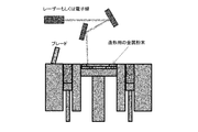
- the additive manufacturing method of laminating a metal layer using a metal powder includes a step of forming a metal powder layer and a metal powder in the area by irradiating a predetermined region of the metal powder layer with a laser or an electron beam.
- the method of alternately repeating the steps of melting and solidifying the powder (powder bed fusion bonding method, PBF: Powder Bed Fusion) and the metal powder continuously injected at the front position in the direction of moving the laser or electron beam.
- PBF Powder Bed Fusion
- the method of irradiating a powder with a laser or an electron beam to melt and solidify is the mainstream.
- DED Directed Energy Deposition
- a selective laser melting method SLM: Selective Laser Melting
- EBM Electron Beam Melting
- the laser for example, a fiber laser or the like can be used.
- Ni-base super heat-resistant alloy (nominal composition is Ni-19) known as UNS N07718 (corresponding to Inconel 718 (registered trademark)) as shown in Patent Document 3 is used.
- Ni-based super heat-resistant alloy powder having a composition corresponding to %Cr-3%Mo-5%(Nb+Ta)-0.9%Ti-0.5%Al-19%Fe) has already been applied, and mainly , It is used for the manufacture of complex shaped members for aircraft that require heat resistance.
- halogen-based gas used as a process gas in semiconductor manufacturing technology ultra-highly purified gas is used, but as the wiring width of semiconductor chips becomes finer, the control of contamination is expected to be severely demanded. Became.
- chemical plants, pharmaceutical equipment, etc. are generally in a severe corrosive environment, although not to the extent of halogen-based gases, and the fluids used often contain chlorine ions, and corrosion resistance to high concentration chlorine ions is desired. ing.
- the design of the members / parts constituting these has become more complicated, and in particular, not only the shape on the outer surface side but also the shape on the inner surface side in direct contact with the gas has been required. Therefore, in die forging and machining, there are demands that exceed the manufacturable range.
- additional manufacturing is being applied in the field of super heat-resistant alloys for the production of members having complicated shapes, a method for producing a corrosion-resistant alloy that can withstand a harsh corrosion environment by the above-mentioned additional manufacturing, and a method thereof No powder suitable for achieving high quality was provided.
- Ni-based corrosion-resistant alloy powder suitable for laminated molding which has excellent corrosion resistance and is capable of imparting a complicated shape with few defects, and a member for a semiconductor manufacturing apparatus using this Ni-based corrosion-resistant alloy powder.
- Ni-based corrosion-resistant alloy powder suitable for laminated molding, which has excellent corrosion resistance and is capable of imparting a complicated shape with few defects, and a member for a semiconductor manufacturing apparatus using this Ni-based corrosion-resistant alloy powder.
- an object of the present invention is to provide a Ni-based corrosion-resistant alloy for additive manufacturing that is excellent in corrosion resistance in a severe corrosive environment (for example, a wet environment containing chlorine or a semiconductor process gas environment) and that is suitable for reducing the defect rate during additive manufacturing. It is an object of the present invention to provide a powder and a method for manufacturing a layered product using this powder.
- a severe corrosive environment for example, a wet environment containing chlorine or a semiconductor process gas environment
- the Ni-based corrosion resistant alloy powder for additive manufacturing of the present invention is, in mass%, Cr: 14.5 to 24.5%, Mo: 12.0 to 23.0%, Fe: 0.01 to 7.00%, Co: 0.001 to 2.500%, Mg: 0.010% or less, N: 0.040% or less, Mn: 0.001 to 0.50%, Si: 0.001 to 0.200%, Al : More than 0 to 0.50%, Ti: 0.001 to 0.500%, Cu: 0.250% or less, V: 0.001 to 0.300%, B: 0.0001 to 0.0050%, Zr: 0.0001 to 0.0200%, O: 0.0010 to 0.0300%, the balance is composed of Ni and unavoidable impurities, and C, S and P contained as the unavoidable impurities are C: Lamination consisting of Ni-based alloy powder having a composition of less than 0.05%, S: less than 0.01%, and P: less than 0.01%, and the repose angle of the Ni-based alloy powder
- Ni-based corrosion resistant alloy powder for modeling It is a Ni-based corrosion resistant alloy powder for modeling.
- This Ni-based corrosion-resistant alloy powder for laminated molding corresponds to an integration frequency of 10% by volume of the powder in an integration distribution curve showing the relationship between the particle size and the volume integration from the small particle size side, which is obtained by the laser diffraction method.
- the particle size d10 is 7 ⁇ m or more and 35 ⁇ m or less
- the particle size d50 corresponding to the integrated frequency of 50% by volume of the powder is 10 ⁇ m or more and 60 ⁇ m or less
- the particle size d90 corresponding to the integrated frequency of 90% by volume of the powder is 20 ⁇ m or more and 98 ⁇ m or less. It is preferable to have.
- the Ni-based corrosion-resistant alloy powder for laminated molding preferably has a uniformity represented by (d90-d10) / d50 of 1.5 or less.
- the component composition may further contain at least one of Ta: 2.5% or less and W: 5.0% or less, if necessary. Ta: more than 1.0 to 2.5%, W: 2.0 to 5.0%.
- the present invention is a method for manufacturing a metal additive-molded product, which performs additive manufacturing using the above Ni-based corrosion-resistant alloy powder for additive manufacturing as a raw material powder. It is preferable that the layered product is a member for a semiconductor manufacturing apparatus. Further, it is preferable that the layered manufacturing at this time is a powder bed fusion bonding method.
- the Ni-based corrosion-resistant alloy powder for laminated molding of the present invention is suitable for suppressing defects, has excellent laying property during laminated molding, and is excellent in laminated molding. Furthermore, a layered product manufactured by additive manufacturing (for example, a semiconductor manufacturing apparatus member/part (hereinafter, simply referred to as “semiconductor manufacturing apparatus member”) and the like has excellent corrosion resistance at least in a wet environment, and further has a Cl content. It exhibits excellent corrosion resistance even in the environment of semiconductor process gases such as 2 , HBr, and NF 3 . Further, when a member for semiconductor manufacturing equipment is manufactured by additive manufacturing using this Ni-based corrosion resistant alloy powder for additive manufacturing, a member for semiconductor manufacturing equipment made of additive manufactured products with few defects and high corrosion resistance is manufactured. Therefore, the degree of freedom in designing the members for the semiconductor manufacturing apparatus is remarkably increased, so that the sophistication of the semiconductor manufacturing apparatus can be realized, and the excellent effect is industrially brought.
- a layered product manufactured by additive manufacturing for example, a semiconductor manufacturing apparatus member/part (
- the schematic of the additive manufacturing apparatus known as a powder bed fusion-bonding method (Powder Bed Fusion method) is shown.
- the schematic diagram of the additive manufacturing apparatus known as a directional energy deposition method (Directed energy deposition method) is shown.
- Ni-based corrosion resistant alloy powder for additive manufacturing hereinafter, also simply referred to as Ni-based corrosion resistant alloy powder
- particle size distribution and the powder particle size will be described. To do.
- Cr 14.5% to 24.5% (% is% by mass, the same applies hereinafter)] Cr is effective in improving corrosion resistance in a corrosive environment.
- a laminated model when used as a member for a semiconductor manufacturing device, it has an effect of improving corrosion resistance against halogen-based gases such as HCl, Cl 2 , HF, F 2 , NF 3 , ClF 3 and HBr. ..
- halogen-based gases such as HCl, Cl 2 , HF, F 2 , NF 3 , ClF 3 and HBr. ..
- the semiconductor manufacturing apparatus member is exposed to the outside air when it is opened, moisture originating from the atmosphere is adsorbed on the metal surface, the adsorbed moisture and the halogen-based process gas are hydrated, and electrochemical corrosion occurs.
- Cr exhibits its corrosion resistance particularly in a region where the concentration is relatively low. In that case, it is necessary to contain Cr in an amount of 14.5% or more, but if it is contained in an amount of more than 24.5%, in combination with Mo, it becomes difficult to maintain a single phase because phase stability is deteriorated during additive manufacturing. It forms a coarse ⁇ phase and causes deterioration of corrosion resistance. Therefore, the content is set to 14.5% to 24.5%.
- the upper limit of Cr is preferably 22.5%, more preferably 20.5%.
- the lower limit of Cr content is preferably 15.0%, and more preferably 18.0%.
- the upper limit value and the lower limit value of the Cr amount can be arbitrarily combined. Although not described below, the upper limit value and the lower limit value can be arbitrarily combined with each element described below.
- Mo 12.0% to 23.0%
- Mo is effective in improving corrosion resistance in a corrosive environment. That is, it has the effect of improving the corrosion resistance against halogen-based gases such as HCl, Cl 2 , HF, F 2 , NF 3 , ClF 3 and HBr.
- halogen-based gases such as HCl, Cl 2 , HF, F 2 , NF 3 , ClF 3 and HBr.
- the content of Mo exceeds 23.0%, Mo is inferior in oxidizability at a high temperature. Therefore, when a powder is produced by a gas atomizing method or the like, The oxide film formed on the surface of each powder becomes thick. It is not preferable because defects due to the oxide become apparent in the layered product manufactured using the powder. Therefore, the content is set to 12.0% to 23.0%.
- the upper limit of Mo content is preferably 20.5%, and more preferably 19.5%. Further, the lower limit of Mo is preferably 14.0%, and more preferably 16.0%.
- Fe and Co have higher melting points than Ni and have the effect of increasing the melt viscosity.
- the powder can be produced, for example, by blowing a molten metal in a spray form in an atmospheric gas to quench it.
- Fe and Co it is possible to easily control the particle size when manufacturing the powder, and to suppress the generation of fine powder (particle size less than 5 ⁇ m) that is difficult to perform additive manufacturing. In that case, it is necessary to contain Fe in an amount of 0.01% or more. However, if the content of Fe exceeds 7.00%, corrosion resistance deteriorates with respect to the hydrated acid. It was set to 7.00%.
- the upper limit of Fe is preferably 5.50%, more preferably 1.00%.
- the lower limit of Fe is preferably 0.05%, more preferably 0.10%.
- Co is required to be contained in an amount of 0.001% or more. However, when it is contained in an amount of more than 2.500%, defects caused by shrinkage cavities at a micro level during solidification of powder during additive manufacturing are generated. It is not preferable because it becomes apparent. Therefore, the Co content is set to 0.001 to 2.500%.
- the upper limit of Co is preferably 1.000%, more preferably 0.500%.
- the lower limit of Co content is preferably 0.005%, more preferably 0.010%.
- N 0.040% or less, Mg: 0.010% or less, Mn: 0.001% to 0.50%
- Mn 0.001% to 0.50%
- the coexistence of N, Mn and Mg has the effect of suppressing microsegregation.
- individual powders are instantly melted by a laser, while being solidified by relatively rapid cooling. At this time, there is a concern that micro-segregation may occur.
- microsegregation occurs, a dilute region of an element exhibiting corrosion resistance such as Cr and Mo is formed, and the corrosion resistance is governed by this dilute region. Therefore, microsegregation should be suppressed as much as possible.
- N, Mn and Mg have the effect of stabilizing the Ni—fcc phase, which is the parent phase, and promoting the solution of Cr and Mo, and as a result, suppress the occurrence of microsegregation during quenching and solidification.
- the content of N is even a very small amount, it has the effect of suppressing microsegregation during laminated molding, but if it is contained in excess of 0.040%, nitrides are formed and defects increase in the laminated model.
- the content was set to 0.040% or less because it causes the problem.
- the upper limit of N is preferably 0.030%, more preferably 0.020%. Further, the lower limit when N is contained is more than 0, preferably 0.001%, more preferably 0.003%, and further preferably 0.005%.
- the Mg content is contained in a very small amount, it has the effect of suppressing microsegregation during laminated molding, but if it is contained in excess of 0.010%, microsegregation is promoted. Since the corrosion resistance of the layered product tends to deteriorate, its content is set to 0.010% or less.
- the preferable upper limit of Mg is 0.0050%, more preferably 0.0030%, and further preferably 0.0020%.
- the lower limit when Mg is contained is more than 0, preferably 0.0001%, more preferably 0.0003%, and even more preferably 0.0005%.
- Mn content is less than 0.001%, there is no effect of suppressing microsegregation during laminated molding, and if it exceeds 0.50%, microsegregation is promoted on the contrary. Since the corrosion resistance of the laminated modeled product to the process gas tends to deteriorate, the content thereof was set to 0.001% to 0.50%.
- the upper limit of Mn is preferably 0.40%, more preferably 0.35%.
- the lower limit of Mn is preferably 0.005%, more preferably 0.006%, and even more preferably 0.007%. It has been confirmed that the effects of these three elements are not equivalent to each other, and that there is no effect of suppressing microsegregation when the three elements are not contained in a predetermined range at the same time.
- Si 0.001% to 0.200%, Al: more than 0 to 0.50%, Ti: 0.001% to 0.500%
- Si, Al, and Ti have the effect of increasing the cleanliness of the alloy when added as deoxidizers.
- the powder-to-powder joining is smoothed during the additive manufacturing, and as a result, defects in the additive manufactured product are suppressed.
- the effect of Si is exhibited when it is contained in an amount of 0.001% or more, but when it is contained in excess of 0.200%, segregation occurs in the grain boundaries and the corrosion resistance tends to deteriorate. Therefore, the Si content is set to 0. It was set to 0.001% to 0.200%.
- a preferable upper limit of Si is 0.100%, and more preferably 0.010%.
- the lower limit of Si content is preferably 0.002%, and more preferably 0.005%.
- the Al content was set to more than 0 to 0.50%.
- the preferable upper limit of Al is 0.40%, and more preferably 0.30%.
- the lower limit of Al is preferably more than 0, preferably 0.001%, more preferably 0.003%, and even more preferably 0.005%.
- the Ti content was set to 0.001% to 0.500%.
- the upper limit of Ti is preferably 0.200%, more preferably 0.100%. Further, the lower limit of Ti is preferably 0.003%, and more preferably 0.005%.
- Cu has the effect of improving corrosion resistance in a reducing wet corrosion environment such as hydrochloric acid and hydrofluoric acid. Therefore, it is effective against the electrochemical corrosion formed by the process gas and the moisture adsorbed on the metal surface. The effect is exhibited by containing even a very small amount of Cu, but if it is contained in excess of 0.250%, the oxide on the surface of the produced powder reveals defects in the laminated model product, so the content of Cu is increased. It was set to 0.250% or less.
- the upper limit of Cu is preferably 0.100%, more preferably 0.010%. Further, the lower limit when Cu is contained is more than 0, preferably 0.001%, more preferably 0.002%, and further preferably 0.005%.
- V has the effect of suppressing the generation of powder having a coarse diameter when the powder is sprayed from the molten metal.
- a powder having an excessively large diameter is not preferable because defects become apparent due to the large gaps between the particles during laminated molding. Therefore, it is removed when the powder is classified, but its yield (powder yield) decreases, which poses a problem in industrial production.
- V is not added in an amount of 0.001% or more, the effect of suppressing coarse powder cannot be obtained.
- V is added in an amount of more than 0.300%, pulverization proceeds conversely, and this also results in a required particle size yield. This is not preferable because it reduces the (powder yield). Therefore, the V content was set to 0.001% to 0.300%.
- the upper limit of V is preferably 0.200%, more preferably 0.100%. Further, the lower limit of V is preferably 0.003%, and more preferably 0.005%.
- B and Zr each become a nucleus in the solidification process and are effective in preventing shrinkage cavities.
- B and Zr each become a nucleus in the solidification process and are effective in preventing shrinkage cavities.
- the process of melting and solidifying individual powders is repeated, but if shrinkage cavities occur in the solidifying process, these defects become the source of particles, so a member for semiconductor manufacturing equipment It becomes unsuitable as a layered product used as a component or a part.
- B is contained in an amount of 0.0001% or more, shrinkage cavities are prevented, but when it is contained in an amount of more than 0.0050%, segregation occurs in grain boundaries and corrosion resistance deteriorates.
- the upper limit of B is preferably 0.0040%, more preferably 0.0030%.
- the lower limit of B is preferably 0.0002%, more preferably 0.0005%.
- the content of Zr is set to 0.0001% to 0.0200%.
- the preferable upper limit of Zr is 0.0100%, more preferably 0.0080%, and further preferably 0.0060%.
- the lower limit of Zr is preferably 0.0005%, more preferably 0.0008%.
- O is mainly instantly bound to Cr in the high temperature state immediately after solidification in the molten metal spraying process during powder production, and forms an extremely thin and strong oxide film on the powder surface, thereby suppressing further oxidation progress. Is effective. As a result, the amount of powder-derived oxide that is mixed as a foreign substance in the laminated modeled product is suppressed to an extremely low level. The effect is exhibited by containing 0.0010% or more of O, but if it is contained in excess of 0.0300%, the oxide on the surface of the powder will reveal defects in the laminated model product. Content was 0.0010% to 0.0300%.
- the preferable upper limit of O is 0.0200%, and more preferably 0.0100%.
- the lower limit of O is preferably 0.0020%, more preferably 0.0050%.
- Ta has the effect of improving the corrosion resistance of reducing acids and oxidizing acids and the corrosion resistance against pitting corrosion and crevice corrosion, and is therefore added as necessary. If added, 2.5% or less is preferable. It should be noted that if the content exceeds 1.0%, the effect of significantly improving the corrosion resistance is exhibited, but if the content exceeds 2.5%, the amount of oxide formed on the powder surface during powder production increases. Therefore, the defects of the laminate become apparent, so that the preferable content is more than 1.0% to 2.5%.
- the preferable upper limit of Ta is 2.3%, and more preferably 2.2%.
- the lower limit of Ta is preferably 1.1%, and more preferably 1.2%.
- W has the effect of improving the corrosion resistance to reducing acids, and at the same time, the viscosity of the molten metal is increased by increasing the melting point, and the particle size can be easily controlled when producing a powder. At the same time, it is possible to suppress the generation of fine powder (particle size less than 5 ⁇ m), which tends to be difficult for additive manufacturing, and therefore, it is added as necessary.
- 5.0% or less is preferable. To obtain that effect, addition of 2.0% or more is preferable.
- the preferable content is 2.0% to 5.0%.
- the preferable upper limit of W is 4.9%, and more preferably 4.5%.
- the lower limit of W is preferably 2.2%, and more preferably 2.5%.
- the component composition of the Ni-based corrosion resistant alloy powder for additive manufacturing of the present invention can be determined by the following measurement method. As described in Examples below, the additive manufacturing powder after classification was dissolved in an appropriate aqueous solution, and the aqueous solution was subjected to high frequency inductively coupled plasma (ICP) analysis to measure the content of a predetermined component. .. A carbon-sulfur analyzer was used for C and S, and an oxygen-nitrogen analyzer was used for N and O, and gas analysis was performed by a combustion method to determine the content thereof.
- ICP inductively coupled plasma
- the Ni-based corrosion resistant alloy powder of the present invention is used for the above-mentioned additive manufacturing (additive manufacturing).
- additive manufacturing additive manufacturing
- metal powder is spread on a stage floor to form a flat and uniform metal powder layer having a thickness of about 20 to 100 ⁇ m. Need to be repeated.
- the surface properties and defects are influenced by the powder properties of the metal powder. Therefore, it is required that the metal powder is supplied without delay, and when squeegeeed, the metal powder efficiently flows and can be spread to have a flat and uniform thickness. That is, good fluidity and good spreadability are required.
- the powder properties, flowability, and spreadability of the Ni-based corrosion resistant alloy powder will be described.
- the fluidity of the Ni-based corrosion resistant alloy powder is evaluated by the angle of repose according to JIS R 9301-2-2. When the angle of repose exceeds 48 degrees, the fluidity is poor and the spreadability is poor.
- the angle of repose needs to be 48 degrees or less, preferably 40 degrees or less.
- the lower limit is not particularly limited, but may be 20 degrees or more, for example.
- the particle size distribution of the Ni-based corrosion resistant alloy powder of the present invention is obtained by a laser diffraction method using a laser diffraction type particle size distribution measuring device.
- the particle size d10 corresponding to the integrated frequency of 10% by volume
- the particle size d50 corresponding to the integrated frequency of 50% by volume
- d10 is 7 ⁇ m or more and 35 ⁇ m or less.
- the lower limit of d10 is preferably 10 ⁇ m.
- the upper limit of d10 is preferably 25 ⁇ m.
- d50 is 10 ⁇ m or more and 60 ⁇ m or less.
- the lower limit of d50 is preferably 20 ⁇ m.
- the upper limit of d50 is preferably 40 ⁇ m.
- d90 is 20 ⁇ m or more and 98 ⁇ m or less.
- the lower limit of d90 is preferably 40 ⁇ m.
- the upper limit of d90 is preferably 80 ⁇ m. If the particles are too small, the powder layer may be worn or biased, resulting in poor coatability.
- the particles are too large, there is a concern that they may remain unmelted due to insufficient laser power, which may affect defects and surface roughness.
- the powder layer can be repeatedly spread to a flat and uniform thickness. Therefore, good spreadability can be obtained.
- the Ni-based alloy powder having the above particle size distribution is suitable for SLM.
- the numerical value represented by (d90-d10) / d50 is defined as uniformity.
- the uniformity of the Ni-based corrosion resistant alloy powder is 1.5 or less, the spreadability becomes good, preferably 1.2 or less, more preferably 1.1 or less.
- the lower limit can be reduced in uniformity by classification or the like, for example, 0.8 or more is preferable, and 0.9 or more is more preferable because the yield of powder and productivity are lowered. It can be said that the smaller the numerical value of the homogeneity represented by the above formula, the narrower the width of the particle size distribution, the smaller the variation, and the more uniform the median diameter.
- the Ni-based corrosion-resistant alloy powder of the present invention has good fluidity and excellent spreadability by providing the above-mentioned angle of repose range and / or the above-mentioned particle size distribution and uniformity. As a result, the defect rate at the time of laminated molding can be reduced, and a laminated model product in which defects are suppressed can be obtained.
- Additive modeling is a modeling method in which melting and solidification of individual powders are repeated to give shape, but if the particle size of the Ni-based corrosion-resistant alloy powder is less than 5 ⁇ m, the volume required for one melting and solidification is large. Since it is difficult to obtain, it is difficult to obtain a sound additive manufacturing product. The small amount of powder having a particle diameter of less than 5 ⁇ m improves the powder yield and contributes to the reduction of the defect rate. On the other hand, if the particle size of the Ni-based corrosion-resistant alloy powder exceeds 100 ⁇ m, the volume required for one melt-solidification is too large, and it is difficult to obtain a sound laminated modeled product.
- the small amount of powder having a particle diameter of more than 100 ⁇ m suppresses laser power shortage and contributes to a reduction in defect rate.
- the particle size distribution range of the Ni-based corrosion resistant alloy powder is more preferably in the range of 20 ⁇ m or more and 80 ⁇ m or less.
- the gas atomization method, the water atomization method, the jet atomization method, etc. can be used for the production of the Ni-based corrosion resistant alloy powder.
- the Ni-based corrosion-resistant alloy powder preferably has a spherical particle shape, and more preferably is produced by a gas atomizing method.
- the Ni-based corrosion resistant alloy powder for additive manufacturing of the present invention can be suitably used for a powder bed method (SLM) using a laser.
- SLM powder bed method
- the Ni-based corrosion resistant alloy powder for additive manufacturing of the present invention is supplied to the additive manufacturing apparatus shown in FIG. 1 and squeegeeed to form a powder layer having a thickness of 20 to 100 ⁇ m, preferably 30 to 60 ⁇ m, and the powder is spread.
- the high energy of which the laser output is adjusted to, for example, 400 W or less is applied to the above region to selectively melt bond the alloy powder.
- the scanning speed at this time may be adjusted to, for example, 7000 mm / s or less.
- the additive manufacturing using the Ni-based corrosion resistant alloy powder for additive manufacturing according to the present invention there are extremely few defects, and a valve member for a cylinder for filling a halogen gas and a halogen compound gas, which has excellent corrosion resistance under a wet environment or a semiconductor process gas environment. It is possible to obtain members for semiconductor manufacturing equipment such as a gas contact member in a mass flow meter, a gas block member, and a gas joint.
- the laminated modeling device not only the one shown in FIG. 1 but also the laminated modeling device of the directed energy deposition method shown in FIG. 2 is used according to the shape and the like of the laminated modeled product. You can also do it.
- the model and the like of the laminated modeling apparatus are not particularly limited.
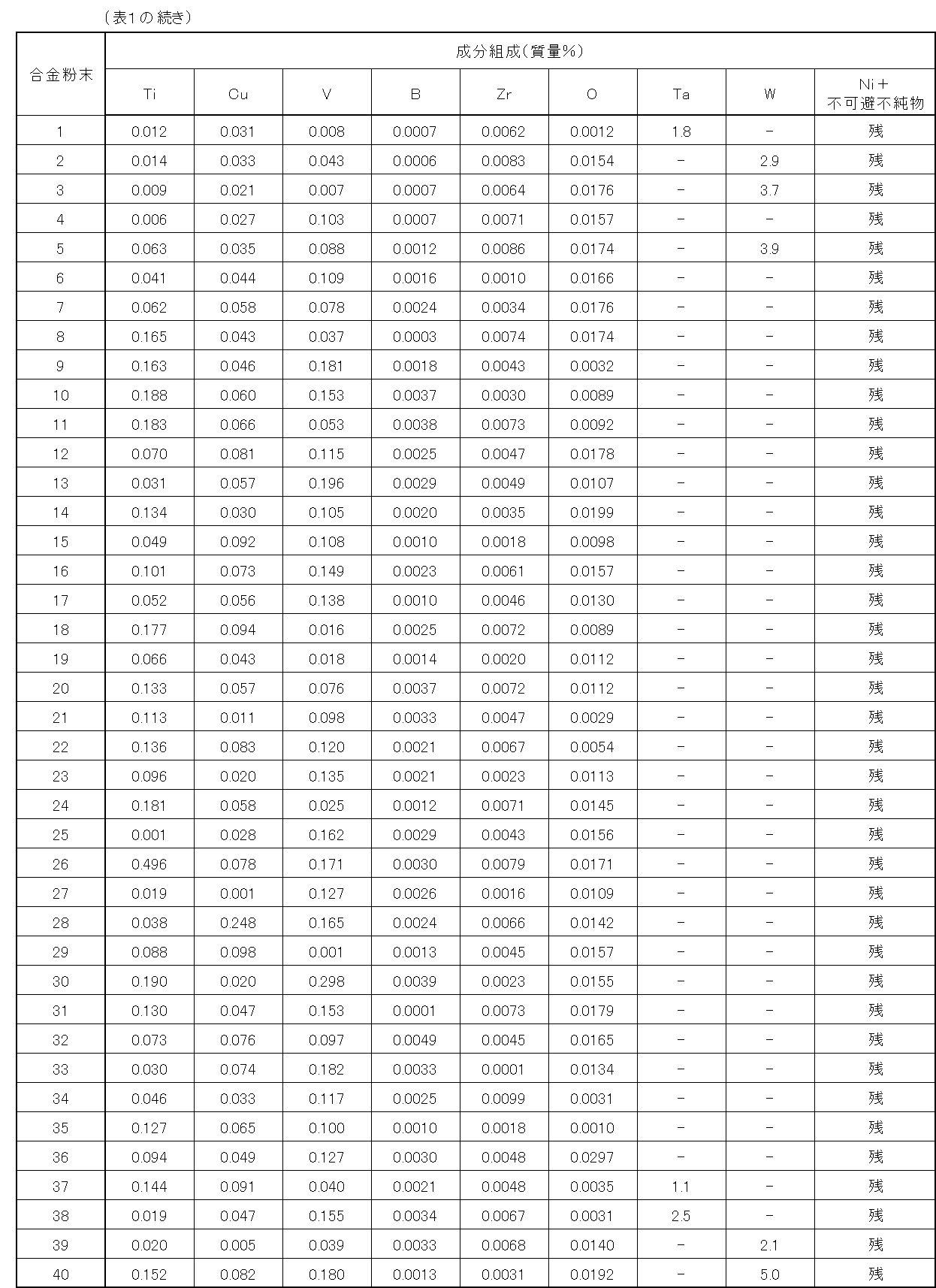
- Example 1 For additive manufacturing, prepare melting materials, melt using a high-frequency vacuum melting furnace, prepare about 10 kg of each mother alloy, and use the gas atomizing method in an argon atmosphere to have the component composition shown in Tables 1 to 4. An elementary powder for obtaining a Ni-based corrosion-resistant alloy powder was produced. Regarding C, S, and P corresponding to unavoidable impurities, C was less than 0.05% and S and P were less than 0.01%. The respective elementary powders obtained in the above gas atomized state were classified into powders having a particle size of 20 to 80 ⁇ m for additive manufacturing and other powders using a plurality of sieves.
- laminating modeling is performed by a powder bed method (SLM) using a laser, and the corrosion resistance (wet environment and semiconductor process gas) of the Ni-based corrosion-resistant alloy powder is confirmed.
- SLM powder bed method
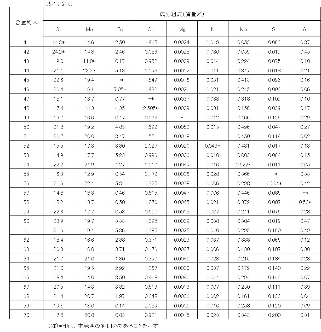
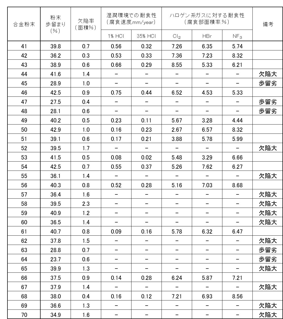
- No. 41 to No. 48, No. 52, No. 54 to No. 60, No. 62 to No. 67, and No. 69 to No. 70 marked with * are in the present invention. This is an example outside the range of the composition.
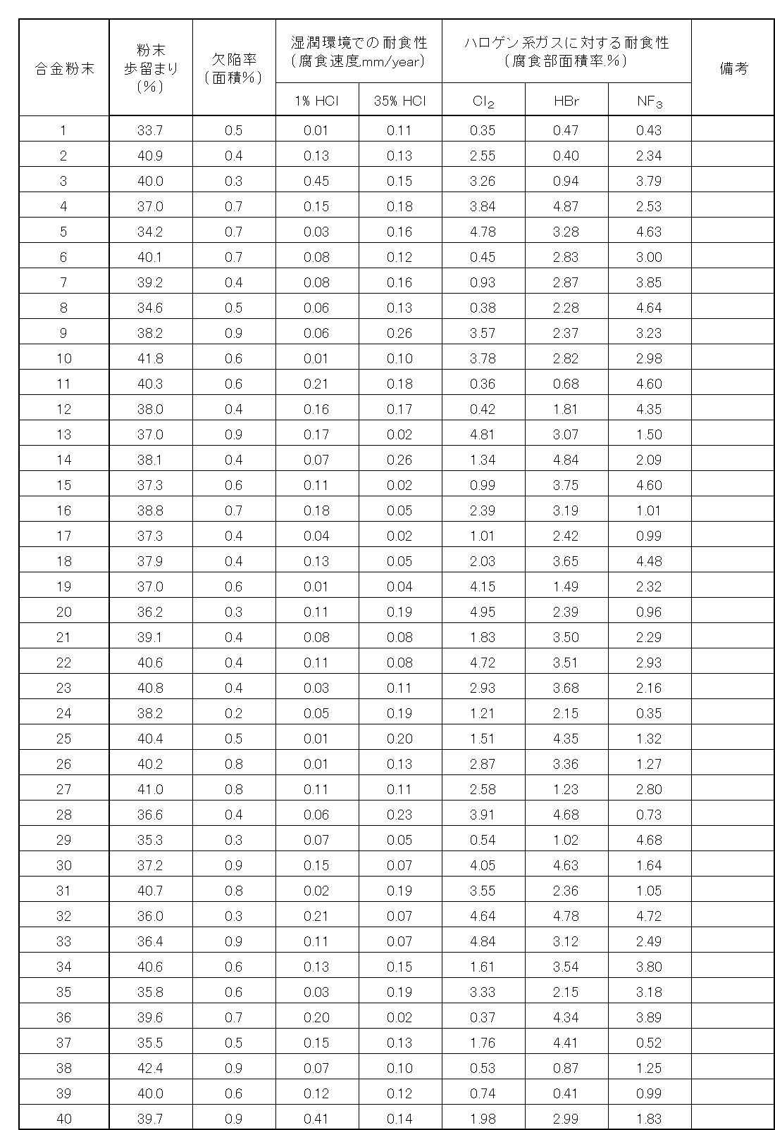
- the powder yield (%) is calculated by (mass of powder having a particle size of 20 to 80 ⁇ m) ⁇ 100/(of the powder as gas atomized). It was calculated as the value of (mass). Tables 5 and 6 show the powder yield (%) values.
- the particle size distribution was measured before classification, but for the powder having excellent yield, the ratio of the powder of less than 5 ⁇ m was 10% or less, and the ratio of the powder of 5 ⁇ m or more was high by adjusting the composition.
- a plate material (30 ⁇ 30 ⁇ 5 mm) as an evaluation laminated model product using Ni-based corrosion-resistant alloy powders 1 to 70 by a powder bed method (SLM) laminated modeling device using a laser shown in FIG. was prepared for each of the 10 powders.
- SLM powder bed method
- a cross section of a plate material (30 ⁇ 30 ⁇ 5 mm) as an additive manufacturing product for evaluation is cut, embedded in a resin, polished to #1500 with water-resistant emery paper, and further polished with a diamond paste having a particle size of 1 ⁇ m to give a mirror-finished surface. And said.
- the mirror-finished surface is observed with an optical microscope, and defects (holes and cavities of 1 ⁇ m square or more) within the area of 1 mm ⁇ 1 mm are identified by an image analyzer (digital microscope VHX6000: made by KEYENCE), and the area is determined.
- the ratio was determined as the defect rate (area %).
- the resolution was 1024x1280pixel, and binarization processing was performed by image analysis software, and a black portion of 8pixel or more was regarded as a defect.
- Tables 5 and 6 show the values of the defect rate (area%).
- the Ni-based corrosion resistant alloy powder for additive manufacturing having the composition according to the present invention has a manufacturing yield, and the defect rate of the additive manufacturing product manufactured using the powder, It was confirmed that both the corrosion resistance (wet environment or semiconductor process gas) was superior to the Ni-based corrosion resistant alloy powder for additive manufacturing outside the present invention and the additive manufacturing product manufactured by using the powder. Further, it was confirmed that by adopting a more preferable composition, high corrosion resistance is exhibited even under the corrosive environment of the semiconductor process gas.
- Example 2 Samples with different particle size distributions were prepared for the No. 1 alloy powder from the Ni-based corrosion resistant alloy powder for additive manufacturing having the above-mentioned composition, and a laser diffraction particle size distribution measuring device (SALD-2300: SHIMADZU) was used. D10, d50, and d90 were measured using, respectively. Further, the uniformity represented by (d90-d10) / d50 was determined. The angle of repose of these samples was measured according to JIS R 9301-2-2. Specifically, an angle of repose measuring device (ASK-01) was used to supply the sample to the saucer and measure the angle of the formed mountain.
- SALD-2300: SHIMADZU laser diffraction particle size distribution measuring device
- Ni-based corrosion-resistant alloy powders were supplied onto the bed and squeezed to form a powder layer having a thickness of 40 to 60 ⁇ m, and the spreadability was evaluated. Visually, if the powder is spread to a uniform thickness, it is considered to be good, and if the powder layer is frayed or biased, it is considered to be poor. NG ". Table 7 shows the results.
- Ni-based corrosion-resistant alloy powder of the present invention as a raw material powder for laminated molding, a laminated molded product having excellent corrosion resistance and extremely few defects can be obtained.
- a member for a semiconductor manufacturing device made of a laminated model but it has a complicated shape not only in a member for a semiconductor manufacturing device but also in a wide range of fields such as a chemical plant, a pharmaceutical manufacturing facility, an oil, and a gas field. It is expected to be applied as a corrosion-resistant metal powder for laminated molding of the members.
Landscapes
- Chemical & Material Sciences (AREA)
- Engineering & Computer Science (AREA)
- Materials Engineering (AREA)
- Manufacturing & Machinery (AREA)
- Mechanical Engineering (AREA)
- Metallurgy (AREA)
- Organic Chemistry (AREA)
- Powder Metallurgy (AREA)
- Laminated Bodies (AREA)
Abstract
Description
なお、前記Ni合金の合金種別を表す「UNS」は、ASEHS-1086とASTMDS-566に規定された「Unified Numbering System」のことであり、前記N06625,N10276,N06022,(後記する)N07718等はこれに登録された合金固有の番号である。
しかし、近年、3Dプリンタと呼ばれる付加製造(Additive Manufacturing)の技術が進歩し、板や棒、パイプのような素形材の機械加工では、形状付与が困難あるいは不可能な複雑形状の付与が可能になってきている。
そして、精度の必要な比較的小型品の製作に際しては、付加製造に適用する原料として、金属粉末も採用されている。
上述のように、超耐熱合金の分野では複雑形状の部材の作製のために付加製造が適用されつつあるものの、過酷な腐食環境下に耐える耐食合金を上述の付加製造で製造する方法、およびそれを高品質で実現するために好適な粉末は提供されていなかった。すなわち、耐食性に優れ、且つ、欠陥が少なく複雑形状の付与が可能となる積層造形に適したNi基耐食合金粉末が強く求められると共に、このNi基耐食合金粉末を用いた半導体製造装置用部材などの積層造形品の開発が強く要望されている。
この積層造形用Ni基耐食合金粉末は、レーザ回折法によって求められる、粒子径と小粒子径側からの体積積算との関係を示す積算分布曲線において、前記粉末の積算頻度10体積%に対応する粒子径d10が7μm以上35μm以下、前記粉末の積算頻度50体積%に対応する粒子径d50が10μm以上60μm以下、前記粉末の積算頻度90体積%に対応する粒子径d90が20μm以上98μm以下、であることが好ましい。
この積層造形用Ni基耐食合金粉末は(d90-d10)/d50で表される均一度が1.5以下であることが良い。
また、前記成分組成には必要に応じて、Ta:2.5%以下、W:5.0%以下の少なくとも一方をさらに含有しても良い。好ましくはTa:1.0超~2.5%、W:2.0~5.0%である。
また、この積層造形用Ni基耐食合金粉末を用いた積層造形により半導体製造装置用部材を製作した場合には、欠陥が少なく、かつ、高耐食性の積層造形品からなる半導体製造装置用部材を製作し得るため、半導体製造装置用部材のデザインの自由度が格段に増し、半導体製造装置の高度化を実現できるようになり、産業上、優れた効果がもたらされる。
Crは、腐食環境における耐食性向上に効果がある。例えば、積層造形品が半導体製造装置用部材として用いられたとすると、HCl,Cl2,HF,F2,NF3,ClF3およびHBrなどのハロゲン系ガスに対して、耐食性を向上させる効果がある。特に、半導体製造装置部材が、開放時に一旦外気に触れた際に、金属表面に大気起源の水分が吸着し、吸着した水分とハロゲン系プロセスガスが水和し、電気化学的腐食が発生する。水和した酸に対して、Crは特に比較的濃度が希薄な領域でその耐食性を発揮する。その場合、Crは14.5%以上含有することが必要であるが、24.5%を超えて含有するとMoとの組み合わせにおいて、積層造形時に相安定性を損ない単一相維持が困難となり、粗大なμ相を形成してしまい耐食性劣化をもたらす。そのため、その含有量を14.5%~24.5%とした。
好ましいCrの上限は、22.5%であり、さらに好ましくは20.5%である。また、好ましいCrの下限は、15.0%であり、さらに好ましくは18.0%である。
上記Cr量の上限値と下限値は任意に組み合わせることができる。また、以下では記載を省略するが、以下に記載する夫々の元素においても上限値と下限値は任意に組み合わせることができる。
Moは、Crと同様に、腐食環境における耐食性向上に効果がある。即ち、HCl,Cl2,HF,F2,NF3,ClF3およびHBrなどのハロゲン系ガスに対して、耐食性を向上させる効果がある。特に、半導体製造装置部材が、開放時に一旦外気に触れた際に、金属表面に大気起源の水分が吸着し、吸着した水分とハロゲン系プロセスガスが水和し、電気化学的腐食が発生する。水和した酸に対して、Moは特に中~高濃度領域でその耐食性を発揮する。その場合、Moは12.0%以上含有することが必要であるが、23.0%を超えて含有すると、Moは高温における酸化性が劣るため、ガスアトマイズ法等によって粉末を製造する際に、個々の粉末表面に形成される酸化膜が厚くなる。その粉末を用いて製造された積層造形品には酸化物起因の欠陥が顕在化してくるため好ましくない。そのため、その含有量を12.0%~23.0%とした。
好ましいMoの上限は、20.5%であり、さらに好ましくは19.5%である。また、好ましいMoの下限は、14.0%であり、さらに好ましくは16.0%である。
FeおよびCoは、Niよりも融点が高く、溶湯粘度を高める効果がある。粉末の製造は、例えば、雰囲気ガス中、溶湯を噴霧状に吹いて急冷させることで得られる。FeおよびCoを添加することにより、粉末を製造する際に、粒径制御が容易になるとともに、積層造形が困難となりやすい微粉(粒径5μm未満)の生成を抑制できる。その場合、Feは0.01%以上含有することが必要であるが、7.00%を超えて含有すると水和した酸に対して耐食性劣化をもたらすので、その含有量を0.01%~7.00%とした。
好ましいFeの上限は、5.50%であり、さらに好ましくは1.00%である。また、好ましいFeの下限は、0.05%であり、さらに好ましくは0.10%である。
同様に、Coは0.001%以上含有することが必要であるが、2.500%を超えて含有すると、積層造形時における粉末の凝固の際のミクロレベルでの引け巣に起因した欠陥が顕在化してくるので好ましくない。そのため、Coの含有量を0.001~2.500%とした。
好ましいCoの上限は、1.000%であり、さらに好ましくは0.500%である。また、好ましいCoの下限は、0.005%であり、さらに好ましくは0.010%である。
N、MnおよびMgを共存させることにより、ミクロ偏析を抑制する効果がある。積層造形する際、個々の粉末はレーザにより瞬間的に溶湯となり、一方、比較的急冷で凝固することにより造形される。この時に、ミクロ偏析が生じる懸念がある。ミクロ偏析が生じることにより、Cr,Mo等の耐食性を発揮する元素の希薄領域が形成され、この希薄領域に耐食性が支配されるので、ミクロ偏析はできるだけ抑制されなければならない。N、MnおよびMgは母相であるNi-fcc相を安定化させ、CrおよびMoの固溶化を促進する効果があるため、結果として、急冷凝固時のミクロ偏析の発生を抑制する。
しかし、Nの含有量は極少量でも含まれていれば積層造形時にミクロ偏析を抑制する効果はあるが、0.040%を超えて含有すると窒化物を形成し、積層造形品に欠陥が増大する原因となるため、その含有量を0.040%以下とした。
好ましいNの上限は、0.030%であり、さらに好ましくは0.020%である。また、Nを含有する場合の下限は、0超であり、好ましくは0.001%であり、より好ましくは0.003%であり、さらに好ましくは0.005%である。
同様に、Mgの含有量は、極少量でも含まれていれば積層造形時にミクロ偏析を抑制する効果はあるが、0.010%を超えて含有すると、逆にミクロ偏析を促進するようになり、積層造形品の耐食性を劣化させる傾向となるため、その含有量を0.010%以下とした。
好ましいMgの上限は、0.0050%であり、より好ましくは0.0030%であり、さらに好ましくは0.0020%である。また、Mgを含有する場合の下限は、0超であり、好ましくは0.0001%であり、より好ましくは0.0003%であり、さらに好ましくは0.0005%である。
一方、Mnの含有量が0.001%未満では、積層造形時にミクロ偏析を抑制する効果は無く、0.50%を超えて含有すると、逆にミクロ偏析を促進するようになり、例えば、半導体プロセスガスに対する積層造形品の耐食性を劣化させる傾向となるため、その含有量を0.001%~0.50%とした。
好ましいMnの上限は、0.40%であり、さらに好ましくは0.35%である。また、好ましいMnの下限は、0.005%であり、より好ましくは0.006%であり、さらに好ましくは0.007%である。
なお、これら3元素の効果はそれぞれ等価ではなく、3元素が同時に所定の範囲で含有されていない場合には、ミクロ偏析を抑制する効果が無いことを確認している。
Si,AlおよびTiは、それぞれ脱酸剤として添加することにより、合金内の清浄度を高める効果がある。これにより、積層造形時に粉と粉の接合が滑らかとなり、結果、積層造形品の欠陥が抑制される。
Siは、0.001%以上含有することで、その効果を示すが、0.200%を超えて含有すると、粒界中に偏析し耐食性が劣化する傾向が現れるため、Siの含有量を0.001%~0.200%とした。
好ましいSiの上限は、0.100%であり、さらに好ましくは0.010%である。また、好ましいSiの下限は、0.002%であり、さらに好ましくは0.005%である。
同様に、Alを極少量でも含有することで、合金内の清浄効果を示すが、0.50%を超えて含有すると、積層造形時の酸化物形成が顕在化し、積層造形品の欠陥が増大する。そのため、Alの含有量を0超~0.50%とした。
好ましいAlの上限は、0.40%であり、さらに好ましくは0.30%である。また、好ましいAlの下限は、0超であり、好ましくは0.001%であり、より好ましくは0.003%であり、さらに好ましくは0.005%である。
同様に、Tiを0.001%以上含有することで、合金内の清浄効果を示すが、0.500%を超えて含有すると、積層造形時の酸化物形成が顕在化し、積層造形品の欠陥が増大する。そのため、Tiの含有量を0.001%~0.500%とした。
好ましいTiの上限は、0.200%であり、さらに好ましくは0.100%である。また、好ましいTiの下限は、0.003%であり、さらに好ましくは0.005%である。
Cuは、塩酸やフッ酸などの還元性の湿潤腐食環境で耐食性を向上させる効果がある。そのため、プロセスガスと金属表面に吸着した水分にて形成される電気化学腐食に対して有効となる。Cuを極少量でも含有することで、効果を示すが、0.250%を超えて含有すると製造した粉末表面の酸化物が積層造形品の欠陥を顕在化させてしまうため、Cuの含有量を0.250%以下とした。
好ましいCuの上限は、0.100%であり、さらに好ましくは0.010%である。また、Cuを含有する場合の下限は、0超であり、好ましくは0.001%であり、より好ましくは0.002%であり、さらに好ましくは0.005%である。
Vは、粉末を溶湯から霧吹き状に製造する際に粗大な径の粉末が生成されることを抑制する効果がある。大き過ぎる径の粉末は、積層造形の際に粒子間の隙間が大きくなることで、欠陥が顕在化してしまうため好ましくない。そのため、粉末を分級する際に除かれるが、その収率(粉末歩留まり)が低下するため、工業生産上の課題となる。Vを0.001%以上添加しなければ、粗大粉末の抑制効果が得られないが、0.300%を超えて含有すると、逆に微粉化が進行し、これも必要な粒径の収率(粉末歩留まり)を低下させることとなるために好ましくない。そのため、Vの含有量を0.001%~0.300%とした。
好ましいVの上限は、0.200%であり、さらに好ましくは0.100%である。また、好ましいVの下限は、0.003%であり、さらに好ましくは0.005%である。
BおよびZrは、それぞれ凝固過程で核となり引け巣発生防止に効果がある。積層造形物を成形する際に、個々の粉末が溶解凝固していく過程が繰り返されるが、凝固過程で引け巣が発生すると、それら欠陥がパーティクルの発生源となるために半導体製造装置用の部材や部品として用いる積層造形物としては不適となってしまう。
Bを0.0001%以上含有することで、引け巣発生防止効果を示すが、0.0050%を超えて含有すると、粒界中に偏析し耐食性が劣化する傾向が現れるため、Bの含有量を0.0001%~0.0050%とした。
好ましいBの上限は、0.0040%であり、さらに好ましくは0.0030%である。また、好ましいBの下限は、0.0002%であり、さらに好ましくは0.0005%である。
同様に、Zrを0.0001%以上含有することで、引け巣発生防止効果を示すが、0.0200%を超えて含有すると、Bと同様に粒界中に偏析し耐食性が劣化する傾向が現れるため、Zrの含有量を0.0001%~0.0200%とした。
好ましいZrの上限は、0.0100%であり、より好ましくは0.0080%であり、さらに好ましくは0.0060%である。また、好ましいZrの下限は、0.0005%であり、さらに好ましくは0.0008%である。
なお、これら2元素の効果はそれぞれ等価ではなく、2元素が同時に所定の範囲で含有されていない場合には、引け巣発生を防止する効果が無いことを確認している。
Oは、粉末製造時の溶湯の噴霧工程で凝固直後の高温状態で、主にCrと瞬時に結びつき、粉末表面に極薄く強固な酸化皮膜を形成することで、それ以上の酸化の進行が抑制される効果がある。これにより、積層造形品に異物として混入してしまう粉末起源の酸化物の量は極めて低く抑制される。Oを0.0010%以上含有することで、その効果を示すが、0.0300%を超えて含有すると粉末表面の酸化物が積層造形品の欠陥を顕在化させてしまうこととなるため、Oの含有量を0.0010%~0.0300%とした。
好ましいOの上限は、0.0200%であり、さらに好ましくは0.0100%である。また、好ましいOの下限は、0.0020%であり、さらに好ましくは0.0050%である。
Taは、還元性酸や酸化性酸での耐食性や、孔食やすきま腐食に対する耐食性を改善する効果があるため、必要に応じて添加する。添加する場合は2.5%以下が良い。なお、1.0%を超えて含有することにより、耐食性を著しく改善する効果が発揮されるが、2.5%を超えて含有すると、粉末製造時に粉末表面に形成される酸化物量が増大し、それにより積層物の欠陥が顕在化するため、好ましい含有量を1.0%超~2.5%とする。
好ましいTaの上限は、2.3%であり、さらに好ましくは2.2%である。また、好ましいTaの下限は、1.1%であり、さらに好ましくは1.2%である。
Wは、Moと同様に還元性酸に対する耐食性を向上させる効果があると同時に、融点を高めることで溶湯の粘度を高め粉末を製造する際に、粒径制御が容易になる。これとともに、積層造形が困難となりやすい微粉(粒径5μm未満)の生成を抑制できるため、必要に応じて添加する。添加する場合は5.0%以下が良い。よりその効果を得るには、2.0%以上の添加が好ましい。しかし、5.0%を超えて含有すると融点が必要以上に高くなるため、粉末が粗大化する傾向となり、適正な粉末径を分級する収率(粉末歩留まり)が落ちる。そのため好ましい含有量を2.0%~5.0%とする。
好ましいWの上限は、4.9%であり、さらに好ましくは4.5%である。また、好ましいWの下限は、2.2%であり、さらに好ましくは2.5%である。
残部はNiおよび不可避不純物である。不可避不純物として、Cは、結晶粒界近傍でCrと炭化物を形成し、耐食性の劣化を増大させる。そのため、Cは0.05%未満とした。また、SやPは粒界に偏析し、高温割れの原因となるため、0.01%未満に抑制しなければならない。
また、これら不可避不純物の含有量は少ないほうが好ましく、0%であっても良い。
後記する実施例でも述べるように、分級後の積層造形用の粉末を適切な水溶液中で溶解し、この水溶液を高周波誘導結合プラズマ(ICP)分析することにより、所定の成分の含有量を測定した。
なお、C、Sについては炭素硫黄分析装置、N、Oについては酸素窒素分析装置を用い、燃焼法によるガス分析を行って、その含有量を求めた。
Ni基耐食合金粉末の流動性は、JIS R9301-2-2に準じる安息角によって評価する。安息角が48度を超えると流動性が悪く敷詰め性は悪くなる。安息角は48度以下であることが必要であり、好ましくは40度以下である。下限は特に限定するものではないが、例えば20度以上にすることができる。
本発明のNi基耐食合金粉末の粒度分布は、レーザ回折式粒度分布測定装置を用いて、レーザ回折法によって求められる。粒子径と小粒子径側からの体積積算との関係を示す積算分布曲線において、積算頻度10体積%に対応する粒子径d10、積算頻度50体積%に対応する粒子径d50および積算頻度90体積%に対応する粒子径d90を測定したとき、d10は7μm以上35μm以下である。d10の下限は、好ましくは10μmである。d10の上限は、好ましくは25μmである。上記d10の上限値と下限値は任意に組み合わせることができる。記載は省略するが、下記するd50、d90についても同様である。
d50は10μm以上60μm以下である。d50の下限は、好ましくは20μmである。d50の上限は、好ましくは40μmである。
d90は20μm以上98μm以下である。d90の下限は、好ましくは40μmである。d90の上限は、好ましくは80μmである。
小さすぎる粒子は粉末層が擦り切れたり偏ったりして塗工性が悪くなる原因となる。一方、大きすぎる粒子はレーザのパワー不足による溶融残りが懸念され欠陥や表面粗さへの影響がでる可能性がある。上記の粒度分布を有することにより、あるいはd50の数値を満足することだけでも、粉末層を平坦で均一な厚さに繰り返し敷き詰めることができる。よって、良好な敷詰め性が得られる。尚、上記の粒度分布を持ったNi基合金粉末はSLM用に適している。
また、本発明において(d90-d10)/d50で表される数値を均一度と定義している。前記Ni基耐食合金粉末の均一度は、1.5以下とすることで敷詰め性良好となり、好ましくは1.2以下、より好ましくは1.1以下である。下限は分級等で均一度の値を小さくすることも可能であるが、粉末の歩留まり、生産性が低下するため、例えば0.8以上が好ましく、0.9以上がより好ましい。上記式で表される均一度は、数値が小さいほど粒度分布の幅が狭く、ばらつきが小さくメジアン径に揃っていると言える。また、均一度の値が小さいほど凝集性が弱く流動性が高く、敷詰め性が高いとも言え、積層造形用に適している。
以上より、上述の安息角の範囲、および/または上述の粒径分布や均一度を備えることで、本発明のNi基耐食合金粉末は流動性が良く敷詰め性に優れる。結果、積層造形時の欠陥率を低減でき、欠陥が抑制された積層造形品を得ることができる。
積層造形は、個々の粉末について溶融と凝固を繰り返すことにより形状付与をしていく造形法であるが、Ni基耐食合金粉末の粒径が5μm未満だと1回の溶融凝固に必要な容積が得にくくなるため、健全な積層造形品が得にくい。粒子径5μm未満の粉末が少ないことで粉末歩留まりが向上し、欠陥率の低減に寄与する。一方、Ni基耐食合金粉末の粒径が100μmを超えると、1回の溶融凝固に必要な容積が大き過ぎ、健全な積層造形品が得にくい。粒子径100μm超の粉末が少ないことでレーザのパワー不足を抑えて、欠陥率の低減に寄与する。中でもSLMによるパウダーベッド法では、5μm以上100μm以下の範囲内に粒径分布範囲を持つNi基耐食合金粉粉末を用いることが好ましい。Ni基耐食合金粉末の粒径分布範囲は、より好ましくは20μm以上80μm以下の範囲内である。
本発明の積層造形用Ni基耐食合金粉末を用いた積層造形によって、欠陥が極めて少なく、湿潤環境下あるいは半導体プロセスガス環境下において優れた耐食性を示すハロゲンガスおよびハロゲン化合物ガス充填用ボンベのバルブ部材、マスフローメーター内の接ガス部材、ガスブロック部材、ガス継手等の半導体製造装置用部材を得ることができる。
また、積層造形装置としては、図1に示すものばかりではなく、積層造形品の形状等に応じて、図2に示す指向性エネルギー堆積方式(Directed energy deposiion法。)の積層造形装置等を使用することもできる。積層造形装置の型式等については特に制限されるものではない。
溶解原料を準備し、高周波真空溶解炉を用いて溶解し、母合金をそれぞれ約10kg作製し、アルゴン雰囲気中、ガスアトマイズ法を用いて、表1~表4に示される成分組成を有する積層造形用Ni基耐食合金粉末を得るための素粉末を製造した。尚、不可避不純物に相当するC、S、Pについては、共にCは0.05%未満、SとPは0.01%未満であった。
上記で得たガスアトマイズしたままのそれぞれの素粉末を、複数のふるいを用いて、積層造形用の粒径20~80μmの粉末とそれ以外の粉末に分級した。
本実施例1では、レーザを用いたパウダーベッド法(SLM)で積層造形を行い、Ni基耐食合金粉末の耐食性(湿潤環境および半導体プロセスガス)等を確認するものである。ここで、表中、*が付記されたNo.41~No.48、No.52、No.54~No.60、No.62~No.67、No.69~No.70は本発明に係る組成の範囲外の例である。なお、積層造形用Ni基耐食合金粉末としての従来品は存在しない。


分級して得た積層造形用の20~80μmの粒径範囲にある粉末について、その粉末歩留まり(%)を、(粒径20~80μmの粉末の質量)×100/(ガスアトマイズしたままの粉末の質量)の値として求めた。
表5および表6に、粉末歩留まり(%)の値を示す。なお、分級前に粒度分布を測定したが、歩留まりに優れた粉末については、5μm未満の粉末の割合が10%以下というもので、組成の調整により5μm以上の粉末の割合が高かった。
これら評価用積層造形品としての板材(30×30×5mm)について、以下の評価を行った。
評価用積層造形品としての板材(30×30×5mm)の断面を切断し、樹脂に埋め込み、耐水エメリー紙で#1500まで研磨後、さらに粒径1μmのダイヤモンドペーストにて研磨し、鏡面仕上げ面とした。
上記鏡面仕上げ面を光学顕微鏡にて観察し、1mm×1mmの範囲内にある欠陥(1μm角以上の空孔、巣)を画像解析装置(デジタルマイクロスコープVHX6000:キーエンス製)により特定し、その面積比率を欠陥率(面積%)として求めた。
なお、解像度は1024x1280pixelで、画像解析ソフトにより、二値化処理をし、8pixel以上の黒色部分を欠陥とした。
表5および表6に、欠陥率(面積%)の値を示す。
評価用積層造形品としての板材(30×30×5mm)の表面を研磨し、最終的に耐水エメリー紙#400仕上げとした。その後、電解研磨をし、研磨後の試料をアセトン中超音波振動状態に5分間保持し脱脂することにより、腐食試験片を作成した。
これら腐食試験片を用いて、沸騰した1%HCl,35%HCl中で24時間の腐食試験を実施した。
その試験前後の重量減少量を測定することにより、試験前表面積と試験期間から腐食速度(mm/year)を算出した。
表5および表6に、その結果を示す。
評価用積層造形品としての板材(30×30×5mm)の表面を研磨し、最終的に耐水エメリー紙#400仕上げとした。その後、電解研磨をし、研磨後の試料をアセトン中超音波振動状態に5分間保持し脱脂することにより、腐食試験片を作成した。
これら腐食試験片を、Ni基合金(UNS N06022)製試験用小型チャンバー内に設置し、真空引き後、腐食ガス(Cl2,HBr,NF3)をそれぞれ充填し、腐食ガスの種類に応じた所定の温度(Cl2:250℃,HBr:250℃,NF3:350℃)に24時間保持し、その後、室温まで冷却し、アルゴンガスに置換後、素早く真空デシケータに保管した。
腐食試験片を、順次、SEM観察に供し、撮影した写真から島状に観察される腐食部分の面積率を画像解析ソフト(winRooF2015)により測定した。
なお、解像度は1024x1280、倍率は500倍で、8ピクセル以上を腐食領域とした。
表5および表6に、その結果を示す。
なお、粉末歩留まりが低い場合や欠陥率が高い比較合金粉末については、腐食試験片は作製せず、耐食性評価も行わなかった。
上述の成分組成の積層造形用Ni基耐食合金粉末の中からNo.1の合金粉末について、異なる粒度分布の試料を作製し、レーザ回折式粒子径分布測定装置(SALD-2300:SHIMADZU製)を用いてd10、d50、d90をそれぞれ測定した。また、(d90-d10)/d50で表される均一度を求めた。
また、これらの試料の安息角をJIS R9301-2-2に準じて測定した。具体的には安息角測定器(ASK-01)を用いて、試料を受け皿に供給し形成された山の角度を測定するようにした。
これらのNi基耐食合金粉末をベッド上に供給し、スキージして厚さ40~60μmの粉末層を形成したときの敷詰め性を評価した。敷詰め性は、目視により、一様な厚さに敷き詰められているものは敷詰め性良好とみなし「良好」、粉末層が擦り切れたり偏ったりしているものは塗工性が悪いとみなし「NG」とした。
表7にその結果を示す。

以上により、これらのNi基耐食合金粉末を用いることにより欠陥率の低い積層造形品を得ることができる。
Claims (8)
- 質量%で、
Cr:14.5~24.5%,
Mo:12.0~23.0%,
Fe:0.01~7.00%,
Co:0.001~2.500%,
Mg:0.010%以下,
N:0.040%以下,
Mn:0.001~0.50%,
Si:0.001~0.200%,
Al:0超~0.50%,
Ti:0.001~0.500%,
Cu:0.250%以下,
V:0.001~0.300%,
B:0.0001~0.0050%,
Zr:0.0001~0.0200%,
O:0.0010~0.0300%,
を含有し、残部がNiおよび不可避不純物からなり、
前記不可避不純物として含まれるC、SおよびPが、それぞれC:0.05%未満、S:0.01%未満およびP:0.01%未満とした成分組成を有するNi基合金の粉末からなり、
前記Ni基合金粉末の安息角が48度以下であることを特徴とする積層造形用Ni基耐食合金粉末。 - 前記Ni基合金粉末は、レーザ回折法によって求められる、粒子径と小粒子径側からの体積積算との関係を示す積算分布曲線において、
前記粉末の積算頻度10体積%に対応する粒子径d10が7μm以上35μm以下、
前記粉末の積算頻度50体積%に対応する粒子径d50が10μm以上60μm以下、
前記粉末の積算頻度90体積%に対応する粒子径d90が20μm以上98μm以下、であることを特徴とする請求項1に記載の積層造形用Ni基耐食合金粉末。 - 前記積算分布曲線において、(d90-d10)/d50で表される均一度が1.5以下であることを特徴とする請求項2に記載の積層造形用Ni基耐食合金粉末。
- 前記Ni基合金の前記成分組成が、Ta:2.5%以下をさらに含有することを特徴とする請求項1~請求項3のいずれか一項に記載の積層造形用Ni基耐食合金粉末。
- 前記Ni基合金の前記成分組成が、W:5.0%以下をさらに含有することを特徴とする請求項1~請求項3のいずれか一項に記載の積層造形用Ni基耐食合金粉末。
- 請求項1~請求項5のいずれか一項に記載の積層造形用Ni基耐食合金粉末を原料粉末として用いて積層造形を行うことを特徴とする積層造形品の製造方法。
- 前記積層造形品が半導体製造装置用部材であることを特徴とする請求項6に記載の積層造形品の製造方法。
- 前記積層造形が粉末床溶融結合方式であることを特徴とする請求項6または請求項7に記載の積層造形品の製造方法。
Priority Applications (6)
| Application Number | Priority Date | Filing Date | Title |
|---|---|---|---|
| US17/434,425 US20220145427A1 (en) | 2019-03-04 | 2019-11-28 | Ni-based corrosion resistant alloy powder for additive manufacturing and manufacturing method of additive manufacturing product using said powder |
| CN201980093172.9A CN113490558B (zh) | 2019-03-04 | 2019-11-28 | 层叠造型用镍基耐腐蚀合金粉末及层叠造型品的制造方法 |
| FIEP19918486.2T FI3936255T3 (fi) | 2019-03-04 | 2019-11-28 | Nikkelipohjainen korroosionkestävä metalliseosjauhe käytettäväksi additiivisessa valmistuksessa sekä menetelmä additiivisessa valmistuksessa käytettävän tuotteen valmistamiseksi samaa jauhetta käyttäen |
| JP2020571561A JP6948584B2 (ja) | 2019-03-04 | 2019-11-28 | 積層造形用Ni基耐食合金粉末、この粉末を用いた積層造形品の製造方法 |
| SG11202109400WA SG11202109400WA (en) | 2019-03-04 | 2019-11-28 | Ni-based corrosion resistant alloy powder for additive manufacturing and manufacturing method of additive manufacturing product using said powder |
| EP19918486.2A EP3936255B1 (en) | 2019-03-04 | 2019-11-28 | Ni-based corrosion-resistant alloy powder for use in additive manufacturing and production method for additive manufacturing product using same powder |
Applications Claiming Priority (4)
| Application Number | Priority Date | Filing Date | Title |
|---|---|---|---|
| JP2019038159 | 2019-03-04 | ||
| JP2019-038157 | 2019-03-04 | ||
| JP2019038157 | 2019-03-04 | ||
| JP2019-038159 | 2019-03-04 |
Publications (1)
| Publication Number | Publication Date |
|---|---|
| WO2020179154A1 true WO2020179154A1 (ja) | 2020-09-10 |
Family
ID=72337858
Family Applications (1)
| Application Number | Title | Priority Date | Filing Date |
|---|---|---|---|
| PCT/JP2019/046502 Ceased WO2020179154A1 (ja) | 2019-03-04 | 2019-11-28 | 積層造形用Ni基耐食合金粉末、この粉末を用いた積層造形品の製造方法 |
Country Status (7)
| Country | Link |
|---|---|
| US (1) | US20220145427A1 (ja) |
| EP (1) | EP3936255B1 (ja) |
| JP (1) | JP6948584B2 (ja) |
| CN (1) | CN113490558B (ja) |
| FI (1) | FI3936255T3 (ja) |
| SG (1) | SG11202109400WA (ja) |
| WO (1) | WO2020179154A1 (ja) |
Cited By (2)
| Publication number | Priority date | Publication date | Assignee | Title |
|---|---|---|---|---|
| JPWO2023136233A1 (ja) * | 2022-01-14 | 2023-07-20 | ||
| WO2025013690A1 (ja) | 2023-07-10 | 2025-01-16 | 三井金属鉱業株式会社 | 金属粉末、金属粉末の製造方法、及び金属粉末を用いた積層造形物の製造方法 |
Families Citing this family (2)
| Publication number | Priority date | Publication date | Assignee | Title |
|---|---|---|---|---|
| CN115344997B (zh) * | 2022-07-11 | 2024-05-31 | 中国水利水电科学研究院 | 夏玉米植株叶片-冠层-像元尺度氮浓度协同预测方法 |
| CN115287501B (zh) * | 2022-08-02 | 2023-04-07 | 中国航发北京航空材料研究院 | 激光增材制造用gh3536高温合金粉末及其制备方法 |
Citations (9)
| Publication number | Priority date | Publication date | Assignee | Title |
|---|---|---|---|---|
| US3046108A (en) | 1958-11-13 | 1962-07-24 | Int Nickel Co | Age-hardenable nickel alloy |
| JPH0747989B2 (ja) | 1992-12-28 | 1995-05-24 | 富士精工株式会社 | 超高純度ガス制御用耐食性バルブ |
| JP2010001558A (ja) | 2008-05-22 | 2010-01-07 | Mitsubishi Materials Corp | ハロゲンガスおよびハロゲン化合物ガス充填用ボンベのバルブ部材 |
| JP2016194143A (ja) * | 2015-03-31 | 2016-11-17 | 山陽特殊製鋼株式会社 | 球状粒子からなる金属粉末 |
| JP2017025392A (ja) * | 2015-07-24 | 2017-02-02 | Jx金属株式会社 | 電子ビーム方式の3dプリンタ用表面処理金属粉およびその製造方法 |
| WO2017026519A1 (ja) * | 2015-08-12 | 2017-02-16 | 山陽特殊製鋼株式会社 | 積層造形用Ni基超合金粉末 |
| JP2017043838A (ja) * | 2015-07-21 | 2017-03-02 | アンサルド エネルジア アイ・ピー ユー・ケイ リミテッドAnsaldo Energia Ip Uk Limited | 粉末ベースの製造プロセスにおいて用いるための高温ニッケル基超合金 |
| JP2018154905A (ja) * | 2017-03-21 | 2018-10-04 | 株式会社リコー | 積層造形用粉末材料、積層造形装置、積層造形用セット及び積層造形方法 |
| WO2019049594A1 (ja) * | 2017-09-07 | 2019-03-14 | 日立金属株式会社 | 積層造形用Ni基耐食合金粉末、この粉末を用いた積層造形品と半導体製造装置用部材の製造方法 |
Family Cites Families (12)
| Publication number | Priority date | Publication date | Assignee | Title |
|---|---|---|---|---|
| JP4981291B2 (ja) * | 2005-09-30 | 2012-07-18 | 株式会社フジミインコーポレーテッド | 溶射用粉末及び溶射皮膜の形成方法 |
| EP2289462B1 (de) * | 2009-08-25 | 2012-05-30 | BEGO Medical GmbH | Vorrichtung und Verfahren zur kontinuierlichen, generativen Fertigung |
| CN106457668A (zh) * | 2014-06-20 | 2017-02-22 | 福吉米株式会社 | 粉末层叠造形中使用的粉末材料和使用其的粉末层叠造形法 |
| CN105290388B (zh) * | 2014-07-04 | 2020-04-07 | 通用电气公司 | 粉末处理方法和相应处理过的粉末 |
| JP6519274B2 (ja) * | 2015-03-30 | 2019-05-29 | 株式会社リコー | 立体造形用粉末材料、立体造形材料セット、立体造形物製造装置、及び立体造形物の製造方法 |
| JP6455328B2 (ja) * | 2015-06-16 | 2019-01-23 | トヨタ自動車株式会社 | 積層造形方法 |
| JP6764228B2 (ja) * | 2015-12-22 | 2020-09-30 | 株式会社フジミインコーポレーテッド | 粉末積層造形に用いるための造形用材料 |
| JP6188171B2 (ja) * | 2016-02-24 | 2017-08-30 | 日立金属Mmcスーパーアロイ株式会社 | 熱間鍛造性に優れた高強度高耐食性Ni基合金 |
| JP2018080359A (ja) * | 2016-11-15 | 2018-05-24 | 株式会社リコー | 立体造形用粉末材料、立体造形材料セット、立体造形物製造装置、及び立体造形物の製造方法 |
| DE102016124588A1 (de) * | 2016-12-16 | 2018-06-21 | Vdm Metals International Gmbh | Verwendung einer nickel-chrom-molybdän-legierung |
| JP2018123375A (ja) * | 2017-02-01 | 2018-08-09 | 山陽特殊製鋼株式会社 | 多孔質粉末及びその製造方法 |
| FI3936257T3 (fi) * | 2019-03-04 | 2025-08-27 | Proterial Ltd | Ni-pohjainen korroosionkestävä seosjauhe additiivista valmistusta varten sekä menetelmä additiivisen valmistustuotteen valmistamiseksi mainittua jauhetta käyttäen |
-
2019
- 2019-11-28 US US17/434,425 patent/US20220145427A1/en active Pending
- 2019-11-28 JP JP2020571561A patent/JP6948584B2/ja active Active
- 2019-11-28 SG SG11202109400WA patent/SG11202109400WA/en unknown
- 2019-11-28 CN CN201980093172.9A patent/CN113490558B/zh active Active
- 2019-11-28 EP EP19918486.2A patent/EP3936255B1/en active Active
- 2019-11-28 FI FIEP19918486.2T patent/FI3936255T3/fi active
- 2019-11-28 WO PCT/JP2019/046502 patent/WO2020179154A1/ja not_active Ceased
Patent Citations (9)
| Publication number | Priority date | Publication date | Assignee | Title |
|---|---|---|---|---|
| US3046108A (en) | 1958-11-13 | 1962-07-24 | Int Nickel Co | Age-hardenable nickel alloy |
| JPH0747989B2 (ja) | 1992-12-28 | 1995-05-24 | 富士精工株式会社 | 超高純度ガス制御用耐食性バルブ |
| JP2010001558A (ja) | 2008-05-22 | 2010-01-07 | Mitsubishi Materials Corp | ハロゲンガスおよびハロゲン化合物ガス充填用ボンベのバルブ部材 |
| JP2016194143A (ja) * | 2015-03-31 | 2016-11-17 | 山陽特殊製鋼株式会社 | 球状粒子からなる金属粉末 |
| JP2017043838A (ja) * | 2015-07-21 | 2017-03-02 | アンサルド エネルジア アイ・ピー ユー・ケイ リミテッドAnsaldo Energia Ip Uk Limited | 粉末ベースの製造プロセスにおいて用いるための高温ニッケル基超合金 |
| JP2017025392A (ja) * | 2015-07-24 | 2017-02-02 | Jx金属株式会社 | 電子ビーム方式の3dプリンタ用表面処理金属粉およびその製造方法 |
| WO2017026519A1 (ja) * | 2015-08-12 | 2017-02-16 | 山陽特殊製鋼株式会社 | 積層造形用Ni基超合金粉末 |
| JP2018154905A (ja) * | 2017-03-21 | 2018-10-04 | 株式会社リコー | 積層造形用粉末材料、積層造形装置、積層造形用セット及び積層造形方法 |
| WO2019049594A1 (ja) * | 2017-09-07 | 2019-03-14 | 日立金属株式会社 | 積層造形用Ni基耐食合金粉末、この粉末を用いた積層造形品と半導体製造装置用部材の製造方法 |
Non-Patent Citations (1)
| Title |
|---|
| See also references of EP3936255A4 |
Cited By (3)
| Publication number | Priority date | Publication date | Assignee | Title |
|---|---|---|---|---|
| JPWO2023136233A1 (ja) * | 2022-01-14 | 2023-07-20 | ||
| WO2023136233A1 (ja) * | 2022-01-14 | 2023-07-20 | 株式会社プロテリアル | 積層造形用リユース合金粉末及び積層造形品の製造方法 |
| WO2025013690A1 (ja) | 2023-07-10 | 2025-01-16 | 三井金属鉱業株式会社 | 金属粉末、金属粉末の製造方法、及び金属粉末を用いた積層造形物の製造方法 |
Also Published As
| Publication number | Publication date |
|---|---|
| EP3936255B1 (en) | 2025-04-02 |
| FI3936255T3 (fi) | 2025-07-10 |
| US20220145427A1 (en) | 2022-05-12 |
| CN113490558B (zh) | 2023-12-22 |
| SG11202109400WA (en) | 2021-09-29 |
| EP3936255A4 (en) | 2022-12-07 |
| JP6948584B2 (ja) | 2021-10-13 |
| CN113490558A (zh) | 2021-10-08 |
| JPWO2020179154A1 (ja) | 2021-04-30 |
| EP3936255A1 (en) | 2022-01-12 |
Similar Documents
| Publication | Publication Date | Title |
|---|---|---|
| JP6519961B2 (ja) | 積層造形用Ni基耐食合金粉末、この粉末を用いた積層造形品と半導体製造装置用部材の製造方法 | |
| JP6864858B2 (ja) | 積層造形用Ni基耐食合金粉末、この粉末を用いた積層造形品の製造方法 | |
| JP6948584B2 (ja) | 積層造形用Ni基耐食合金粉末、この粉末を用いた積層造形品の製造方法 | |
| JP6690789B2 (ja) | 合金材、該合金材を用いた製造物、および該製造物を有する流体機械 | |
| JP2017222929A (ja) | Ni基超合金組成物、及びかかるNi基超合金組成物をSLM加工するための方法 | |
| JP7521174B2 (ja) | 積層造形体および積層造形体の製造方法 | |
| JP7524547B2 (ja) | Cr-Ni系合金部材およびその製造方法 | |
| JP7103548B2 (ja) | Ni-Cr-Mo系合金部材、Ni-Cr-Mo系合金粉末、および、複合部材 | |
| JP7318819B2 (ja) | Ni基合金粉末およびこのNi基合金粉末を用いた積層造形品の製造方法 | |
| JP7589859B2 (ja) | 積層造形用Ni基合金粉末、積層造形品、及び積層造形品の製造方法 | |
| US12605765B2 (en) | Powder material | |
| EP4567144A1 (en) | Fe-cr-al-based alloy powder for additive manufacturing, fe-cr-al-based alloy member, and method for producing fe-cr-al-based alloy member | |
| JP7677529B2 (ja) | 積層造形体からなるNi-Cr合金部材、Ni-Cr合金部材の製造方法、およびNi-Cr合金部材を用いた製造物 | |
| JP7830017B2 (ja) | 組織中にP相を有するNiCrMo系合金からなる積層造形体 | |
| CN110699574A (zh) | 一种用于增材制造的铝合金粉末 |
Legal Events
| Date | Code | Title | Description |
|---|---|---|---|
| 121 | Ep: the epo has been informed by wipo that ep was designated in this application |
Ref document number: 19918486 Country of ref document: EP Kind code of ref document: A1 |
|
| ENP | Entry into the national phase |
Ref document number: 2020571561 Country of ref document: JP Kind code of ref document: A |
|
| NENP | Non-entry into the national phase |
Ref country code: DE |
|
| ENP | Entry into the national phase |
Ref document number: 2019918486 Country of ref document: EP Effective date: 20211004 |
|
| WWG | Wipo information: grant in national office |
Ref document number: 2019918486 Country of ref document: EP |