WO2020180162A1 - 영상 부호화/복호화 방법, 장치 및 비트스트림을 저장한 기록 매체 - Google Patents
영상 부호화/복호화 방법, 장치 및 비트스트림을 저장한 기록 매체 Download PDFInfo
- Publication number
- WO2020180162A1 WO2020180162A1 PCT/KR2020/003205 KR2020003205W WO2020180162A1 WO 2020180162 A1 WO2020180162 A1 WO 2020180162A1 KR 2020003205 W KR2020003205 W KR 2020003205W WO 2020180162 A1 WO2020180162 A1 WO 2020180162A1
- Authority
- WO
- WIPO (PCT)
- Prior art keywords
- block
- transform
- mode
- transformation
- current block
- Prior art date
- Legal status (The legal status is an assumption and is not a legal conclusion. Google has not performed a legal analysis and makes no representation as to the accuracy of the status listed.)
- Ceased
Links
Images









Classifications
-
- H—ELECTRICITY
- H04—ELECTRIC COMMUNICATION TECHNIQUE
- H04N—PICTORIAL COMMUNICATION, e.g. TELEVISION
- H04N19/00—Methods or arrangements for coding, decoding, compressing or decompressing digital video signals
- H04N19/60—Methods or arrangements for coding, decoding, compressing or decompressing digital video signals using transform coding
- H04N19/61—Methods or arrangements for coding, decoding, compressing or decompressing digital video signals using transform coding in combination with predictive coding
-
- H—ELECTRICITY
- H04—ELECTRIC COMMUNICATION TECHNIQUE
- H04N—PICTORIAL COMMUNICATION, e.g. TELEVISION
- H04N19/00—Methods or arrangements for coding, decoding, compressing or decompressing digital video signals
- H04N19/10—Methods or arrangements for coding, decoding, compressing or decompressing digital video signals using adaptive coding
- H04N19/102—Methods or arrangements for coding, decoding, compressing or decompressing digital video signals using adaptive coding characterised by the element, parameter or selection affected or controlled by the adaptive coding
- H04N19/12—Selection from among a plurality of transforms or standards, e.g. selection between discrete cosine transform [DCT] and sub-band transform or selection between H.263 and H.264
-
- H—ELECTRICITY
- H04—ELECTRIC COMMUNICATION TECHNIQUE
- H04N—PICTORIAL COMMUNICATION, e.g. TELEVISION
- H04N19/00—Methods or arrangements for coding, decoding, compressing or decompressing digital video signals
- H04N19/10—Methods or arrangements for coding, decoding, compressing or decompressing digital video signals using adaptive coding
- H04N19/102—Methods or arrangements for coding, decoding, compressing or decompressing digital video signals using adaptive coding characterised by the element, parameter or selection affected or controlled by the adaptive coding
- H04N19/129—Scanning of coding units, e.g. zig-zag scan of transform coefficients or flexible macroblock ordering [FMO]
-
- H—ELECTRICITY
- H04—ELECTRIC COMMUNICATION TECHNIQUE
- H04N—PICTORIAL COMMUNICATION, e.g. TELEVISION
- H04N19/00—Methods or arrangements for coding, decoding, compressing or decompressing digital video signals
- H04N19/10—Methods or arrangements for coding, decoding, compressing or decompressing digital video signals using adaptive coding
- H04N19/102—Methods or arrangements for coding, decoding, compressing or decompressing digital video signals using adaptive coding characterised by the element, parameter or selection affected or controlled by the adaptive coding
- H04N19/103—Selection of coding mode or of prediction mode
-
- H—ELECTRICITY
- H04—ELECTRIC COMMUNICATION TECHNIQUE
- H04N—PICTORIAL COMMUNICATION, e.g. TELEVISION
- H04N19/00—Methods or arrangements for coding, decoding, compressing or decompressing digital video signals
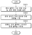
- H04N19/10—Methods or arrangements for coding, decoding, compressing or decompressing digital video signals using adaptive coding
- H04N19/102—Methods or arrangements for coding, decoding, compressing or decompressing digital video signals using adaptive coding characterised by the element, parameter or selection affected or controlled by the adaptive coding
- H04N19/103—Selection of coding mode or of prediction mode
- H04N19/105—Selection of the reference unit for prediction within a chosen coding or prediction mode, e.g. adaptive choice of position and number of pixels used for prediction
-
- H—ELECTRICITY
- H04—ELECTRIC COMMUNICATION TECHNIQUE
- H04N—PICTORIAL COMMUNICATION, e.g. TELEVISION
- H04N19/00—Methods or arrangements for coding, decoding, compressing or decompressing digital video signals
- H04N19/10—Methods or arrangements for coding, decoding, compressing or decompressing digital video signals using adaptive coding
- H04N19/102—Methods or arrangements for coding, decoding, compressing or decompressing digital video signals using adaptive coding characterised by the element, parameter or selection affected or controlled by the adaptive coding
- H04N19/103—Selection of coding mode or of prediction mode
- H04N19/11—Selection of coding mode or of prediction mode among a plurality of spatial predictive coding modes
-
- H—ELECTRICITY
- H04—ELECTRIC COMMUNICATION TECHNIQUE
- H04N—PICTORIAL COMMUNICATION, e.g. TELEVISION
- H04N19/00—Methods or arrangements for coding, decoding, compressing or decompressing digital video signals
- H04N19/10—Methods or arrangements for coding, decoding, compressing or decompressing digital video signals using adaptive coding
- H04N19/102—Methods or arrangements for coding, decoding, compressing or decompressing digital video signals using adaptive coding characterised by the element, parameter or selection affected or controlled by the adaptive coding
- H04N19/119—Adaptive subdivision aspects, e.g. subdivision of a picture into rectangular or non-rectangular coding blocks
-
- H—ELECTRICITY
- H04—ELECTRIC COMMUNICATION TECHNIQUE
- H04N—PICTORIAL COMMUNICATION, e.g. TELEVISION
- H04N19/00—Methods or arrangements for coding, decoding, compressing or decompressing digital video signals
- H04N19/10—Methods or arrangements for coding, decoding, compressing or decompressing digital video signals using adaptive coding
- H04N19/102—Methods or arrangements for coding, decoding, compressing or decompressing digital video signals using adaptive coding characterised by the element, parameter or selection affected or controlled by the adaptive coding
- H04N19/124—Quantisation
-
- H—ELECTRICITY
- H04—ELECTRIC COMMUNICATION TECHNIQUE
- H04N—PICTORIAL COMMUNICATION, e.g. TELEVISION
- H04N19/00—Methods or arrangements for coding, decoding, compressing or decompressing digital video signals
- H04N19/10—Methods or arrangements for coding, decoding, compressing or decompressing digital video signals using adaptive coding
- H04N19/134—Methods or arrangements for coding, decoding, compressing or decompressing digital video signals using adaptive coding characterised by the element, parameter or criterion affecting or controlling the adaptive coding
-
- H—ELECTRICITY
- H04—ELECTRIC COMMUNICATION TECHNIQUE
- H04N—PICTORIAL COMMUNICATION, e.g. TELEVISION
- H04N19/00—Methods or arrangements for coding, decoding, compressing or decompressing digital video signals
- H04N19/10—Methods or arrangements for coding, decoding, compressing or decompressing digital video signals using adaptive coding
- H04N19/134—Methods or arrangements for coding, decoding, compressing or decompressing digital video signals using adaptive coding characterised by the element, parameter or criterion affecting or controlling the adaptive coding
- H04N19/136—Incoming video signal characteristics or properties
-
- H—ELECTRICITY
- H04—ELECTRIC COMMUNICATION TECHNIQUE
- H04N—PICTORIAL COMMUNICATION, e.g. TELEVISION
- H04N19/00—Methods or arrangements for coding, decoding, compressing or decompressing digital video signals
- H04N19/10—Methods or arrangements for coding, decoding, compressing or decompressing digital video signals using adaptive coding
- H04N19/169—Methods or arrangements for coding, decoding, compressing or decompressing digital video signals using adaptive coding characterised by the coding unit, i.e. the structural portion or semantic portion of the video signal being the object or the subject of the adaptive coding
- H04N19/17—Methods or arrangements for coding, decoding, compressing or decompressing digital video signals using adaptive coding characterised by the coding unit, i.e. the structural portion or semantic portion of the video signal being the object or the subject of the adaptive coding the unit being an image region, e.g. an object
- H04N19/176—Methods or arrangements for coding, decoding, compressing or decompressing digital video signals using adaptive coding characterised by the coding unit, i.e. the structural portion or semantic portion of the video signal being the object or the subject of the adaptive coding the unit being an image region, e.g. an object the region being a block, e.g. a macroblock
-
- H—ELECTRICITY
- H04—ELECTRIC COMMUNICATION TECHNIQUE
- H04N—PICTORIAL COMMUNICATION, e.g. TELEVISION
- H04N19/00—Methods or arrangements for coding, decoding, compressing or decompressing digital video signals
- H04N19/10—Methods or arrangements for coding, decoding, compressing or decompressing digital video signals using adaptive coding
- H04N19/169—Methods or arrangements for coding, decoding, compressing or decompressing digital video signals using adaptive coding characterised by the coding unit, i.e. the structural portion or semantic portion of the video signal being the object or the subject of the adaptive coding
- H04N19/186—Methods or arrangements for coding, decoding, compressing or decompressing digital video signals using adaptive coding characterised by the coding unit, i.e. the structural portion or semantic portion of the video signal being the object or the subject of the adaptive coding the unit being a colour or a chrominance component
-
- H—ELECTRICITY
- H04—ELECTRIC COMMUNICATION TECHNIQUE
- H04N—PICTORIAL COMMUNICATION, e.g. TELEVISION
- H04N19/00—Methods or arrangements for coding, decoding, compressing or decompressing digital video signals
- H04N19/50—Methods or arrangements for coding, decoding, compressing or decompressing digital video signals using predictive coding
- H04N19/503—Methods or arrangements for coding, decoding, compressing or decompressing digital video signals using predictive coding involving temporal prediction
-
- H—ELECTRICITY
- H04—ELECTRIC COMMUNICATION TECHNIQUE
- H04N—PICTORIAL COMMUNICATION, e.g. TELEVISION
- H04N19/00—Methods or arrangements for coding, decoding, compressing or decompressing digital video signals
- H04N19/50—Methods or arrangements for coding, decoding, compressing or decompressing digital video signals using predictive coding
- H04N19/503—Methods or arrangements for coding, decoding, compressing or decompressing digital video signals using predictive coding involving temporal prediction
- H04N19/51—Motion estimation or motion compensation
-
- H—ELECTRICITY
- H04—ELECTRIC COMMUNICATION TECHNIQUE
- H04N—PICTORIAL COMMUNICATION, e.g. TELEVISION
- H04N19/00—Methods or arrangements for coding, decoding, compressing or decompressing digital video signals
- H04N19/50—Methods or arrangements for coding, decoding, compressing or decompressing digital video signals using predictive coding
- H04N19/593—Methods or arrangements for coding, decoding, compressing or decompressing digital video signals using predictive coding involving spatial prediction techniques
-
- H—ELECTRICITY
- H04—ELECTRIC COMMUNICATION TECHNIQUE
- H04N—PICTORIAL COMMUNICATION, e.g. TELEVISION
- H04N19/00—Methods or arrangements for coding, decoding, compressing or decompressing digital video signals
- H04N19/60—Methods or arrangements for coding, decoding, compressing or decompressing digital video signals using transform coding
-
- H—ELECTRICITY
- H04—ELECTRIC COMMUNICATION TECHNIQUE
- H04N—PICTORIAL COMMUNICATION, e.g. TELEVISION
- H04N19/00—Methods or arrangements for coding, decoding, compressing or decompressing digital video signals
- H04N19/60—Methods or arrangements for coding, decoding, compressing or decompressing digital video signals using transform coding
- H04N19/625—Methods or arrangements for coding, decoding, compressing or decompressing digital video signals using transform coding using discrete cosine transform [DCT]
-
- H—ELECTRICITY
- H04—ELECTRIC COMMUNICATION TECHNIQUE
- H04N—PICTORIAL COMMUNICATION, e.g. TELEVISION
- H04N19/00—Methods or arrangements for coding, decoding, compressing or decompressing digital video signals
- H04N19/70—Methods or arrangements for coding, decoding, compressing or decompressing digital video signals characterised by syntax aspects related to video coding, e.g. related to compression standards
-
- H—ELECTRICITY
- H04—ELECTRIC COMMUNICATION TECHNIQUE
- H04N—PICTORIAL COMMUNICATION, e.g. TELEVISION
- H04N19/00—Methods or arrangements for coding, decoding, compressing or decompressing digital video signals
- H04N19/90—Methods or arrangements for coding, decoding, compressing or decompressing digital video signals using coding techniques not provided for in groups H04N19/10-H04N19/85, e.g. fractals
- H04N19/91—Entropy coding, e.g. variable length coding [VLC] or arithmetic coding
Definitions
- the present invention relates to a method and apparatus for encoding/decoding an image, and more particularly, to a method and apparatus for encoding/decoding a video image based on an adaptive transformation type selection.
- High-resolution and high-quality images such as high definition (HD) images and ultra high definition (UHD) images is increasing in various application fields.
- the higher the resolution and quality of the video data the higher the amount of data is compared to the existing video data. Therefore, if the video data is transmitted using a medium such as a wired/wireless broadband line or stored using an existing storage medium, the transmission cost and The storage cost increases.
- High-efficiency image encoding/decoding technology for an image having a higher resolution and image quality is required to solve these problems that occur as image data becomes high-resolution and high-quality.
- An inter-screen prediction technology that predicts pixel values included in the current picture from a picture before or after the current picture with an image compression technology
- an intra prediction technology that predicts a pixel value included in the current picture using pixel information in the current picture
- Various technologies exist such as transformation and quantization technology for compressing the energy of the residual signal, and entropy coding technology that allocates short codes to values with a high frequency of appearance and long codes to values with low frequency of appearance.
- Image data can be effectively compressed and transmitted or stored.
- An object of the present invention is to provide a video encoding/decoding method and apparatus with improved encoding/decoding efficiency.
- Another object of the present invention is to provide a method and apparatus for encoding/decoding an image based on transformation, shuffling, rearrangement, and/or flipping for improving encoding/decoding efficiency.
- an object of the present invention is to provide a video encoding/decoding method and apparatus based on adaptive transformation type selection to improve encoding/decoding efficiency.
- Another object of the present invention is to provide an image encoding/decoding method and apparatus for improving image conversion efficiency.
- An image decoding method includes determining a horizontal transformation type and a vertical transformation type of a current block; Deriving a residual block of the current block by performing inverse transform on the current block based on the determined horizontal transform type and vertical transform type; And restoring the current block based on the residual block, wherein the determining of the horizontal transformation type and the vertical transformation type comprises: when the current block is in an Intra Sub-block Partitions (ISP) mode, the current It may be performed based on at least one of a horizontal size and a vertical size of the current block regardless of the intra prediction mode of the block.
- ISP Intra Sub-block Partitions
- the determining of the horizontal transformation type and the vertical transformation type may further include setting implicit multiple transformation selection information.
- the setting of the implicit multi-transformation selection information comprises: when the current block is in an ISP (Intra Sub-block Partitions) mode, the implicit multi-transformation selection information is a value indicating implicit multi-transformation selection. Can be set to
- the setting of the implicit multi-transform selection information comprises: indicating that intra prediction explicit multi-transform selection permission information does not allow explicit multi-transform selection, and the prediction mode of the current block is In an intra prediction mode, when the second inverse transform is not performed on the current block, and the current block is not a matrix-based intra prediction mode, the implicit multi-transform selection information may be set to a value indicating implicit multi-transform selection. I can.
- the horizontal transformation type and the vertical transformation type are determined based on whether the current block is in a Sub-Block Transform (SBT) mode. Can be determined.
- SBT Sub-Block Transform
- the implicit multi-transform selection information indicates implicit multi-transform selection and the current block is not in a Sub-Block Transform (SBT) mode, regardless of an intra prediction mode of the current block
- SBT Sub-Block Transform
- the horizontal transformation type and the vertical transformation type are DCT regardless of the implicit multiple transformation selection information. It may be determined as a first transformation indicating a -2 based integer transformation.
- the determining of the horizontal transformation type and the vertical transformation type comprises: when the current block is a color difference component, the horizontal transformation type and the vertical transformation type are DCT regardless of the implicit multiple transformation selection information. It may be determined as a first transformation indicating a -2 based integer transformation.
- An image encoding method includes determining a horizontal transformation type and a vertical transformation type of a current block; Performing a transformation on the residual block of the current block based on the determined horizontal transformation type and vertical transformation type; And encoding the current block based on the transformed residual block, wherein the determining of the horizontal transformation type and the vertical transformation type comprises: when the current block is in an Intra Sub-block Partitions (ISP) mode, It may be performed based on at least one of a horizontal size and a vertical size of the current block regardless of the intra prediction mode of the current block.
- ISP Intra Sub-block Partitions
- the determining of the horizontal transformation type and the vertical transformation type may further include setting implicit multiple transformation selection information.
- the setting of the implicit multi-transform selection information comprises: when the current block is in an ISP (Intra Sub-block Partitions) mode, the implicit multi-transform selection information is a value indicating implicit multi-transform selection. Can be set to
- the setting of the implicit multi-transform selection information comprises: indicating that intra prediction explicit multi-transform selection permission information does not allow explicit multi-transform selection, and the prediction mode of the current block is In an intra prediction mode, when the second inverse transform is not performed on the current block, and the current block is not a matrix-based intra prediction mode, the implicit multi-transform selection information may be set to a value indicating implicit multi-transform selection. I can.
- the horizontal transformation type and the vertical transformation type are determined based on whether the current block is in a Sub-Block Transform (SBT) mode. Can be determined.
- SBT Sub-Block Transform
- the implicit multi-transform selection information indicates implicit multi-transform selection and the current block is not in a Sub-Block Transform (SBT) mode, regardless of an intra prediction mode of the current block
- SBT Sub-Block Transform
- the horizontal transform type and the vertical transform type are DCT regardless of the implicit multiple transform selection information. It may be determined as a first transformation indicating a -2 based integer transformation.
- the determining of the horizontal transformation type and the vertical transformation type comprises: when the current block is a color difference component, the horizontal transformation type and the vertical transformation type are DCT regardless of the implicit multiple transformation selection information. It may be determined as a first transformation indicating a -2 based integer transformation.
- a computer-readable recording medium is a non-transitory computer-readable recording medium storing a bitstream generated by an image encoding method, the image encoding method comprising: a horizontal transformation type of a current block and Determining a vertical transformation type; Performing a transformation on the residual block of the current block based on the determined horizontal transformation type and vertical transformation type; And encoding the current block based on the transformed residual block, wherein the determining of the horizontal transformation type and the vertical transformation type comprises: when the current block is in an Intra Sub-block Partitions (ISP) mode, It may be performed based on at least one of a horizontal size and a vertical size of the current block regardless of the intra prediction mode of the current block.
- ISP Intra Sub-block Partitions
- an image encoding/decoding method and apparatus with improved encoding/decoding efficiency can be provided.
- a method and apparatus for encoding/decoding an image based on transformation, shuffling, rearrangement, and/or flipping for improving encoding/decoding efficiency may be provided.
- an image encoding/decoding method and apparatus based on adaptive transformation type selection for improving encoding/decoding efficiency may be provided.
- an image encoding/decoding method and apparatus for improving image conversion efficiency may be provided.
- a recording medium storing a bitstream generated by the video encoding/decoding method or apparatus of the present invention can be provided.
- FIG. 1 is a block diagram showing a configuration according to an embodiment of an encoding apparatus to which the present invention is applied.
- FIG. 2 is a block diagram showing a configuration according to an embodiment of a decoding apparatus to which the present invention is applied.
- FIG. 3 is a diagram schematically illustrating a split structure of an image when encoding and decoding an image.
- FIG. 4 is a diagram for describing an embodiment of an intra prediction process.
- 5 is a diagram for describing an embodiment of an inter prediction process.
- FIG. 6 is a diagram for describing a process of transformation and quantization.
- FIG. 7 is a diagram showing a basis vector in the frequency domain of DCT-2 according to the present invention.
- FIG. 8 is a diagram showing a basis vector in each frequency domain of DST-7 according to the present invention.
- 9 is a 2Nx2N prediction unit (PU) of an 8x8 coding unit (CU) predicted by an inter mode, obtained by experimenting a “Cactus” sequence in a Low Delay-P profile environment. ) It is a diagram showing the distribution of the average residual value according to the inner position.
- 10 is a 3D graph showing residual signal distribution characteristics in a 2Nx2N prediction unit PU of an 8x8 coding unit CU predicted in an inter mode prediction mode.
- FIG. 11 is a diagram showing distribution characteristics of residual signals in a 2Nx2N prediction unit (PU) mode of a coding unit (CU) according to the present invention.
- FIG. 12 is a diagram showing residual signal distribution characteristics before and after shuffling of a 2Nx2N prediction unit PU according to the present invention.
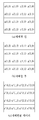
- FIG. 13 is a diagram illustrating an example of rearrangement of 4x4 residual data of a subblock according to the present invention.
- FIG. 14(a) and 14(b) illustrate an embodiment of a split structure of a transform unit (TU) of a coding unit (CU) and a shuffling method of the transform unit (TU) according to a prediction unit (PU) mode. It is a drawing for explanation.
- 15 is a diagram illustrating a result of performing DCT-2 transformation and SDST transformation according to a residual signal distribution of a 2Nx2N prediction unit PU.
- 16 is a diagram illustrating an SDST process according to the present invention.
- FIG. 17 is a diagram for explaining a distribution characteristic of a division of a transform unit (TU) for each prediction unit (PU) partition mode of an inter prediction coding unit (CU) and a size of a residual absolute value according to the present invention to be.
- TU transform unit
- PU prediction unit
- CU inter prediction coding unit
- FIG. 18 is a diagram for explaining a residual signal scanning sequence and a rearrangement sequence of a transform unit TU having a depth of 0 in a prediction unit PU according to an embodiment of the present invention.
- FIG. 19 is a flowchart showing a DCT-2 or SDST selective encoding process through rate-distortion optimization (RDO) according to the present invention.
- 20 is a flowchart illustrating a process of selecting and decoding DCT-2 or SDST according to the present invention.
- 21 is a flowchart showing a decoding process using SDST according to the present invention.
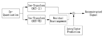
- 22 and 23 respectively show positions where residual rearrangement is performed in the encoder and decoder according to the present invention.
- 24 is a diagram for explaining an embodiment of a decoding method using the SDST method according to the present invention.
- 25 is a diagram for describing an embodiment of an encoding method using the SDST method according to the present invention.
- 26 is a diagram illustrating an embodiment of an encoding process of a method of performing transformation after flipping.
- FIG. 27 is a diagram for describing an embodiment of a decoding process of a method of performing flipping after inverse transformation.
- FIG. 28 is a diagram for explaining an embodiment of an encoding process of a method of performing flipping after transformation.
- 29 is a diagram illustrating an embodiment of a decoding process of a method of performing inverse transform after flipping.
- FIG. 30 is a diagram for explaining an embodiment of an encoding process of a method of performing flipping after quantization.
- FIG. 31 is a diagram illustrating an embodiment of a decoding process of a method of performing inverse quantization after flipping.
- 32 is a diagram for describing flipping on a residual block.
- 33 is a diagram illustrating an embodiment for implementing flipping on a residual block having a size of 8x8 in hardware.
- 34 is a diagram for explaining flipping and transforming a residual block.
- 35 to 37 are diagrams for explaining embodiments of a first subblock division mode according to the present invention.
- 38 is a diagram for explaining an embodiment of a second subblock division mode according to the present invention.
- 39 is a diagram for describing an embodiment of a diagonal scan.
- 40 is a diagram for describing an embodiment of a horizontal scan.
- 41 is a diagram for describing an embodiment of a vertical scan.
- FIG. 42 is a diagram for describing an embodiment of a block-based diagonal scan.
- 43 is a diagram for describing an embodiment of a block-based horizontal scan.
- 44 is a diagram for describing an embodiment of a block-based vertical scan.
- 45 is a diagram for describing an embodiment of a block-based horizontal scan.
- 46 is a diagram for describing an embodiment of a block-based vertical scan.
- 47 is a diagram for describing various embodiments of a scan based on a block shape.
- 48 is a diagram for describing an intra prediction mode.
- 49 is a diagram for describing reference samples usable for intra prediction.
- 50 to 54 are examples of an encoding process or a decoding process using transformation according to an embodiment of the present invention.
- 55 is a diagram for describing an image decoding method according to an embodiment of the present invention.
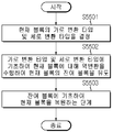
- 56 is a diagram for describing an image encoding method according to an embodiment of the present invention.
- first and second may be used to describe various components, but the components should not be limited by the terms. These terms are used only for the purpose of distinguishing one component from another component.
- a first element may be referred to as a second element, and similarly, a second element may be referred to as a first element.
- the term and/or includes a combination of a plurality of related listed items or any of a plurality of related listed items.
- a component of the present invention When a component of the present invention is referred to as being “connected” or “connected” to another component, it may be directly connected or connected to the other component, but other components exist in the middle. It should be understood that it may be possible. On the other hand, when a component is referred to as being “directly connected” or “directly connected” to another component, it should be understood that there is no other component in the middle.
- each component shown in the embodiments of the present invention is independently shown to represent different characteristic functions, and does not mean that each component is formed of separate hardware or a single software component. That is, each constituent part is listed and included as a respective constituent part for convenience of explanation, and at least two of the constituent parts are combined to form one constituent part, or one constituent part is divided into a plurality of constituent parts to perform a function. Integrated embodiments and separate embodiments of the components are also included in the scope of the present invention unless departing from the essence of the present invention.
- Some of the components of the present invention are not essential components that perform essential functions in the present invention, but may be optional components only for improving performance.
- the present invention can be implemented by including only the components essential to implement the essence of the present invention excluding components used for performance improvement, and a structure including only essential components excluding optional components used for performance improvement Also included in the scope of the present invention.
- an image may mean one picture constituting a video, and may represent a video itself.
- encoding and/or decoding of an image may mean “encoding and/or decoding of a video” and “encoding and/or decoding of one of the images constituting a video” May be.
- the target image may be an encoding target image that is an encoding target and/or a decoding target image that is a decoding target.
- the target image may be an input image input through an encoding device or an input image input through a decoding device.
- the target image may have the same meaning as the current image.
- image image
- picture picture
- the target block may be an encoding target block that is an object of encoding and/or a decoding object block that is an object of decoding.
- the target block may be a current block that is a target of current encoding and/or decoding.
- target block and current block may have the same meaning, and may be used interchangeably.
- block and “unit” may be used with the same meaning, and may be used interchangeably. Or “block” may represent a specific unit.
- region and “segment” may be used interchangeably.
- the specific signal may be a signal indicating a specific block.
- the original signal may be a signal representing a target block.
- the prediction signal may be a signal representing a prediction block.
- the residual signal may be a signal indicating a residual block.
- each of the specified information, data, flag, index and element, attribute, and the like may have a value.
- a value "0" of information, data, flags, indexes, elements, attributes, etc. may represent a logical false or a first predefined value. That is to say, the value "0", false, logical false, and the first predefined value may be replaced with each other and used.
- a value "1" of information, data, flags, indexes, elements, attributes, etc. may represent a logical true or a second predefined value. That is to say, the value "1", true, logical true and the second predefined value may be used interchangeably.
- i When a variable such as i or j is used to indicate a row, column, or index, the value of i may be an integer greater than or equal to 0, or may be an integer greater than or equal to 1. That is to say, in embodiments, rows, columns, and indexes may be counted from 0, and may be counted from 1.
- Encoder refers to a device that performs encoding. That is, it may mean an encoding device.
- Decoder refers to a device that performs decoding. That is, it may mean a decoding device.
- MxN array of samples M and N may mean positive integer values, and a block may often mean a two-dimensional array of samples.
- a block can mean a unit.
- the current block may mean an encoding object block, which is an object of encoding during encoding, and a decoding object block, which is an object of decoding when decoding. Also, the current block may be at least one of a coding block, a prediction block, a residual block, and a transform block.
- Sample A basic unit that composes a block. It may be expressed as a value from 0 to 2 Bd -1 according to the bit depth (B d ).
- B d bit depth
- a sample may be used in the same sense as a pixel or a pixel. That is, samples, pixels, and pixels may have the same meaning.
- Unit It may mean a unit of image encoding and decoding.
- a unit may be a region obtained by dividing one image. Further, a unit may mean a divided unit when one image is divided into subdivided units and encoded or decoded. That is, one image may be divided into a plurality of units.
- a predefined process may be performed for each unit.
- One unit may be further divided into sub-units having a smaller size than the unit.
- the units are Block, Macroblock, Coding Tree Unit, Coding Tree Block, Coding Unit, Coding Block, and Prediction.
- a unit may mean a unit (Prediction Unit), a prediction block (Prediction Block), a residual unit (Residual Unit), a residual block (Residual Block), a transform unit (Transform Unit), a transform block (Transform Block), and the like.
- a unit may mean including a luminance component block, a chrominance component block corresponding thereto, and a syntax element for each block in order to distinguish it from a block.
- the unit may have various sizes and shapes, and in particular, the shape of the unit may include not only a square, but also a geometric figure that can be expressed in two dimensions, such as a rectangle, a trapezoid, a triangle, and a pentagon.
- the unit information may include at least one of a type of a unit indicating a coding unit, a prediction unit, a residual unit, a transform unit, and the like, a size of a unit, a depth of a unit, and an order of encoding and decoding units.
- Coding Tree Unit It is composed of two color difference component (Cb, Cr) coded tree blocks related to one luminance component (Y) coded tree block. In addition, it may mean including the blocks and a syntax element for each block.
- Each coding tree unit uses one or more partitioning methods, such as a quad tree, a binary tree, and a ternary tree, to construct subunits such as coding units, prediction units, and transform units. Can be divided. Like division of an input image, it may be used as a term to refer to a sample block that becomes a processing unit in an image decoding/encoding process.
- the quad tree may mean a quadrilateral tree.
- the predetermined range may be defined as at least one of a maximum size and a minimum size of a coding block that can be divided only by a quadtree.
- Information indicating the maximum/minimum size of a coding block in which quadtree-type division is allowed can be signaled through a bitstream, and the information is in at least one unit of a sequence, a picture parameter, a tile group, or a slice (segment). Can be signaled.
- the maximum/minimum size of the coding block may be a fixed size pre-set in the encoder/decoder.
- the size of the coding block when the size of the coding block corresponds to 256x256 to 64x64, it may be split only into a quadtree.
- the size of the coding block when the size of the coding block is larger than the size of the maximum transform block, it may be divided only into a quadtree.
- the divided block may be at least one of a coding block or a transform block.
- the information indicating splitting of the coding block (eg, split_flag) may be a flag indicating whether to split the quadtree.
- split_flag When the size of the coded block falls within a predetermined range, it may be divided into a binary tree or a three-division tree. In this case, the above description of the quad tree can be applied equally to a binary tree or a three-division tree.
- Coding Tree Block It can be used as a term for referring to any one of a Y-coded tree block, a Cb-coded tree block, and a Cr-coded tree block.
- Neighbor block May mean a block adjacent to the current block.
- a block adjacent to the current block may refer to a block facing the current block or a block located within a predetermined distance from the current block.
- the neighboring block may mean a block adjacent to the vertex of the current block.
- the block adjacent to the vertex of the current block may be a block vertically adjacent to a neighboring block horizontally adjacent to the current block or a block horizontally adjacent to a neighboring block vertically adjacent to the current block.
- the neighboring block may mean a restored neighboring block.
- Reconstructed Neighbor Block This may mean a neighboring block that has already been encoded or decoded in a spatial/temporal manner around the current block.
- the restored neighboring block may mean a restored neighboring unit.
- the reconstructed spatial neighboring block may be a block in the current picture and already reconstructed through encoding and/or decoding.
- the reconstructed temporal neighboring block may be a reconstructed block or a neighboring block at a position corresponding to the current block of the current picture in the reference image.
- Unit Depth It may mean the degree to which a unit is divided.
- the root node in the tree structure may correspond to the first undivided unit.
- the highest node may be referred to as a root node.
- the highest node may have a minimum depth value.
- the uppermost node may have a depth of level 0.
- a node having a depth of level 1 may represent a unit generated as the first unit is divided once.
- a node with a depth of level 2 may represent a unit created as the first unit is divided twice.
- a node having a depth of level n may represent a unit generated when the first unit is divided n times.
- the leaf node may be the lowest node, and may be a node that cannot be further divided.
- the depth of the leaf node may be at the maximum level.
- a predefined value of the maximum level may be 3. It can be said that the root node has the shallowest depth, and the leaf node has the deepest depth.
- the level at which the unit exists may mean the unit depth.
- Bitstream May mean a sequence of bits including coded image information.
- Parameter Set Corresponds to header information among structures in the bitstream. At least one of a video parameter set, a sequence parameter set, a picture parameter set, and an adaptation parameter set may be included in the parameter set. Also, the parameter set may include tile group, slice header, and tile header information. In addition, the tile group may mean a group including several tiles, and may have the same meaning as a slice.
- the adaptation parameter set may refer to a parameter set that can be shared by referring to different pictures, subpictures, slices, tile groups, tiles, or bricks.
- information in the adaptation parameter set may be used in subpictures, slices, tile groups, tiles, or bricks within a picture by referring to different adaptation parameter sets.
- adaptation parameter set may refer to different adaptation parameter sets by using identifiers of different adaptation parameter sets in subpictures, slices, tile groups, tiles, or bricks within a picture.
- the adaptation parameter set may refer to different adaptation parameter sets by using identifiers of different adaptation parameter sets in a slice, a tile group, a tile, or a brick within a subpicture.
- adaptation parameter sets may refer to different adaptation parameter sets by using identifiers of different adaptation parameter sets in tiles or bricks within a slice.
- adaptation parameter sets may refer to different adaptation parameter sets by using identifiers of different adaptation parameter sets in bricks within the tile.
- an adaptation parameter set corresponding to the adaptation parameter set identifier may be used in the subpicture.
- an adaptation parameter set corresponding to the adaptation parameter set identifier may be used in the tile.
- an adaptation parameter set corresponding to the adaptation parameter set identifier may be used in the brick.
- the picture may be divided into one or more tile rows and one or more tile columns.
- the subpicture may be divided into one or more tile rows and one or more tile columns within the picture.
- the subpicture is an area having a rectangular/square shape within a picture, and may include one or more CTUs.
- at least one tile/brick/slice may be included in one subpicture.
- the tile is an area having a rectangular/square shape within a picture, and may include one or more CTUs. Also, a tile can be divided into one or more bricks.
- the brick may mean one or more CTU rows in the tile.
- a tile can be divided into one or more bricks, and each brick can have at least one or more CTU rows. Tiles that are not divided into two or more can also mean bricks.
- the slice may include one or more tiles in a picture, and may include one or more bricks in the tile.
- Parsing It may mean determining a value of a syntax element by entropy decoding a bitstream, or it may mean entropy decoding itself.
- Symbol It may mean at least one of a syntax element of an encoding/decoding target unit, a coding parameter, and a value of a transform coefficient. Also, the symbol may mean an object of entropy encoding or a result of entropy decoding.
- Prediction Mode This may be information indicating a mode encoded/decoded by intra prediction or a mode encoded/decoded by inter prediction.
- Prediction Unit It may mean a basic unit when prediction is performed, such as inter prediction, intra prediction, inter prediction, inter-screen compensation, and motion compensation.
- One prediction unit may be divided into a plurality of partitions having a smaller size or a plurality of sub prediction units.
- the plurality of partitions may also be basic units in performing prediction or compensation.
- a partition generated by division of a prediction unit may also be a prediction unit.
- Prediction Unit Partition This may mean a form in which a prediction unit is divided.
- Reference Picture List This may mean a list including one or more reference pictures used for inter prediction or motion compensation.
- the types of the reference image list may include LC (List Combined), L0 (List 0), L1 (List 1), L2 (List 2), L3 (List 3), and more than one reference image for inter prediction. Lists can be used.
- Inter prediction indicator may mean an inter prediction direction (unidirectional prediction, bidirectional prediction, etc.) of the current block. Alternatively, it may mean the number of reference pictures used when generating a prediction block of the current block. Alternatively, it may mean the number of prediction blocks used when inter prediction or motion compensation is performed on the current block.
- Prediction list utilization flag Indicates whether a prediction block is generated using at least one reference image in a specific reference image list.
- An inter prediction indicator can be derived using the prediction list utilization flag, and conversely, the prediction list utilization flag can be derived using an inter prediction indicator. For example, when the prediction list utilization flag indicates a first value of 0, it may indicate that a prediction block is not generated using a reference image in the reference image list, and when a second value of 1 is indicated, the reference It may indicate that a prediction block can be generated using an image list.
- Reference Picture Index This may mean an index indicating a specific reference picture in the reference picture list.
- Reference Picture This may mean an image referenced by a specific block for inter-screen prediction or motion compensation.
- the reference image may be an image including a reference block referenced by the current block for inter prediction or motion compensation.
- reference picture and reference image may be used with the same meaning, and may be used interchangeably.
- Motion Vector It may be a 2D vector used for inter-screen prediction or motion compensation.
- the motion vector may mean an offset between an encoding/decoding object block and a reference block.
- (mvX, mvY) may represent a motion vector.
- mvX may represent a horizontal component
- mvY may represent a vertical component.
- the search range may be a two-dimensional area in which a motion vector is searched during inter prediction.
- the size of the search area may be MxN.
- M and N may each be a positive integer.
- Motion Vector Candidate When predicting a motion vector, it may mean a block to be a prediction candidate or a motion vector of the block. Also, the motion vector candidate may be included in the motion vector candidate list.
- Motion Vector Candidate List This may mean a list constructed by using one or more motion vector candidates.
- Motion Vector Candidate Index May mean an indicator indicating a motion vector candidate in the motion vector candidate list. It may be an index of a motion vector predictor.
- Motion Information At least one of a motion vector, a reference image index, an inter prediction indicator, as well as a prediction list utilization flag, reference image list information, reference image, motion vector candidate, motion vector candidate index, merge candidate, merge index, etc. It may mean information including one.
- Merge Candidate List This may mean a list formed by using one or more merge candidates.
- the merge candidate may include motion information such as an inter prediction indicator, a reference image index for each list, a motion vector, a prediction list utilization flag, and an inter prediction indicator.
- Merge Index May mean an indicator indicating a merge candidate in the merge candidate list.
- the merge index may indicate a block from which a merge candidate is derived from among blocks reconstructed spatially/temporally adjacent to the current block.
- the merge index may indicate at least one of motion information of the merge candidate.
- Transform Unit It may mean a basic unit when encoding/decoding a residual signal such as transform, inverse transform, quantization, inverse quantization, and transform coefficient encoding/decoding.
- One transform unit may be divided into a plurality of sub-transform units having a smaller size.
- the transform/inverse transform may include at least one of a first-order transform/inverse transform and a second-order transform/inverse transform.
- Scaling This may mean a process of multiplying a quantized level by a factor. Transform coefficients can be generated as a result of scaling for the quantized level. Scaling can also be called dequantization.
- Quantization Parameter In quantization, it may mean a value used when generating a quantized level using a transform coefficient. Alternatively, it may mean a value used when generating a transform coefficient by scaling a quantized level in inverse quantization.
- the quantization parameter may be a value mapped to a quantization step size.
- Residual quantization parameter (Delta Quantization Parameter): This may mean a difference value between the predicted quantization parameter and the quantization parameter of the encoding/decoding target unit.
- Scan This can mean a method of arranging the order of coefficients within a unit, block, or matrix. For example, sorting a two-dimensional array into a one-dimensional array is called a scan. Alternatively, arranging a one-dimensional array into a two-dimensional array may also be referred to as a scan or an inverse scan.
- Transform Coefficient This may mean a coefficient value generated after transformation is performed by an encoder. Alternatively, it may mean a coefficient value generated after performing at least one of entropy decoding and inverse quantization in the decoder. A quantized level obtained by applying quantization to a transform coefficient or a residual signal or a quantized transform coefficient level may also be included in the meaning of the transform coefficient.
- Quantized Level This may mean a value generated by quantizing a transform coefficient or a residual signal in an encoder. Alternatively, it may mean a value that is the target of inverse quantization before the decoder performs inverse quantization. Similarly, a quantized transform coefficient level resulting from transform and quantization may also be included in the meaning of the quantized level.
- Non-zero transform coefficient This may mean a transform coefficient whose size is not 0, or a transform coefficient level whose size is not 0 or a quantized level.
- Quantization Matrix This may mean a matrix used in a quantization or inverse quantization process in order to improve subjective or objective quality of an image.
- the quantization matrix may also be called a scaling list.
- Quantization Matrix Coefficient May mean each element in a quantization matrix.
- the quantization matrix coefficient may also be referred to as a matrix coefficient.
- Default matrix This may mean a predetermined quantization matrix defined in advance in an encoder and a decoder.
- Non-default Matrix This may mean a quantization matrix that is not predefined by an encoder and a decoder and is signaled by a user.
- the statistical value for at least one of the variables, encoding parameters, constants, etc. that has specific operable values is the average value, weighted average value, weighted sum, minimum value, maximum value, mode, median value, interpolation It may be at least one or more of the values.
- FIG. 1 is a block diagram showing a configuration according to an embodiment of an encoding apparatus to which the present invention is applied.
- the encoding device 100 may be an encoder, a video encoding device, or an image encoding device.
- a video may include one or more images.
- the encoding apparatus 100 may sequentially encode one or more images.
- the encoding apparatus 100 includes a motion prediction unit 111, a motion compensation unit 112, an intra prediction unit 120, a switch 115, a subtractor 125, a transform unit 130, and a quantization unit.
- a unit 140, an entropy encoder 150, an inverse quantization unit 160, an inverse transform unit 170, an adder 175, a filter unit 180, and a reference picture buffer 190 may be included.
- the encoding apparatus 100 may encode an input image in an intra mode and/or an inter mode. Also, the encoding apparatus 100 may generate a bitstream including information encoded by encoding an input image, and may output the generated bitstream. The generated bitstream may be stored in a computer-readable recording medium or streamed through a wired/wireless transmission medium.
- the intra mode is used as the prediction mode
- the switch 115 may be switched to intra
- the inter mode may mean an inter prediction mode.
- the encoding apparatus 100 may generate a prediction block for an input block of an input image.
- the encoding apparatus 100 may encode the residual block by using a residual between the input block and the prediction block.
- the input image may be referred to as a current image that is a current encoding target.
- the input block may be referred to as a current block or a current block to be encoded.
- the intra prediction unit 120 may use a sample of a block already encoded/decoded around the current block as a reference sample.
- the intra prediction unit 120 may perform spatial prediction for the current block using the reference sample, and may generate prediction samples for the input block through spatial prediction.
- intra prediction may mean intra prediction.
- the motion prediction unit 111 may search for an area that best matches the input block from the reference image in the motion prediction process, and may derive a motion vector using the searched area. .
- a search area may be used as the area.
- the reference image may be stored in the reference picture buffer 190.
- it when encoding/decoding of the reference image is processed, it may be stored in the reference picture buffer 190.
- the motion compensation unit 112 may generate a prediction block for the current block by performing motion compensation using a motion vector.
- inter prediction may mean inter prediction or motion compensation.
- the motion prediction unit 111 and the motion compensation unit 112 may generate a prediction block by applying an interpolation filter to a partial region of a reference image.
- the motion prediction and motion compensation method of the prediction unit included in the corresponding coding unit based on the coding unit is a skip mode, merge mode, and improved motion vector prediction ( It is possible to determine whether the method is an Advanced Motion Vector Prediction (AMVP) mode or a current picture reference mode, and perform inter prediction or motion compensation according to each mode.
- AMVP Advanced Motion Vector Prediction
- the subtractor 125 may generate a residual block by using a difference between the input block and the prediction block.
- the residual block may be referred to as a residual signal.
- the residual signal may mean a difference between the original signal and the predicted signal.
- the residual signal may be a signal generated by transforming, quantizing, or transforming and quantizing a difference between the original signal and the predicted signal.
- the residual block may be a residual signal in units of blocks.
- the transform unit 130 may transform the residual block to generate a transform coefficient, and may output the generated transform coefficient.
- the transform coefficient may be a coefficient value generated by performing transform on the residual block.
- the transform unit 130 may omit the transform of the residual block.
- a quantized level may be generated by applying quantization to a transform coefficient or a residual signal.
- the quantized level may also be referred to as a transform coefficient.
- the quantization unit 140 may generate a quantized level by quantizing a transform coefficient or a residual signal according to a quantization parameter, and may output the generated quantized level. In this case, the quantization unit 140 may quantize the transform coefficient using a quantization matrix.
- the entropy encoding unit 150 may generate a bitstream by performing entropy encoding according to a probability distribution on values calculated by the quantization unit 140 or values of a coding parameter calculated during an encoding process. Yes, and can output a bitstream.
- the entropy encoder 150 may perform entropy encoding on information about a sample of an image and information for decoding an image. For example, information for decoding an image may include a syntax element or the like.
- the entropy encoding unit 150 may use an encoding method such as exponential Golomb, Context-Adaptive Variable Length Coding (CAVLC), and Context-Adaptive Binary Arithmetic Coding (CABAC) for entropy encoding.
- CAVLC Context-Adaptive Variable Length Coding
- CABAC Context-Adaptive Binary Arithmetic Coding
- the entropy encoding unit 150 may perform entropy encoding using a variable length encoding (VLC) table.
- VLC variable length encoding
- the entropy encoding unit 150 derives the binarization method of the target symbol and the probability model of the target symbol/bin, and then the derived binarization method, probability model, and context model. Arithmetic coding can also be performed using.
- the entropy encoder 150 may change a two-dimensional block form coefficient into a one-dimensional vector form through a transform coefficient scanning method in order to encode a transform coefficient level (quantized level).
- the coding parameter may include information (flags, indexes, etc.) encoded by the encoder and signaled by the decoder, such as syntax elements, as well as information derived during the encoding process or the decoding process, and the image is to be encoded or decoded. It can mean the information you need at the time.
- signaling a flag or index may mean that the encoder entropy encodes the flag or index and includes the corresponding flag or index in the bitstream. It may mean entropy decoding.
- the encoded current image may be used as a reference image for another image to be processed later. Accordingly, the encoding apparatus 100 may reconstruct or decode the encoded current image again, and store the reconstructed or decoded image as a reference image in the reference picture buffer 190.
- the quantized level may be dequantized by the inverse quantization unit 160. It may be inverse transformed by the inverse transform unit 170.
- the inverse quantized and/or inverse transformed coefficient may be summed with the prediction block through the adder 175, and a reconstructed block may be generated by adding the inverse quantized and/or inverse transformed coefficient and the prediction block.
- the inverse quantized and/or inverse transformed coefficient means a coefficient in which at least one of inverse quantization and inverse transform is performed, and may mean a reconstructed residual block.
- the restoration block may pass through the filter unit 180.
- the filter unit 180 converts at least one such as a deblocking filter, a sample adaptive offset (SAO), and an adaptive loop filter (ALF) to a reconstructed sample, a reconstructed block, or a reconstructed image. Can be applied.
- the filter unit 180 may also be referred to as an in-loop filter.
- the deblocking filter may remove block distortion occurring at the boundary between blocks.
- it may be determined whether to apply the deblocking filter to the current block based on samples included in several columns or rows included in the block.
- different filters can be applied according to the required deblocking filtering strength.
- An appropriate offset value may be added to a sample value to compensate for an encoding error using a sample adaptive offset.
- the sample adaptive offset may correct an offset from the original image in units of samples for the deblocking image. After dividing the samples included in the image into a certain number of areas, a method of determining an area to perform offset and applying an offset to the corresponding area, or a method of applying an offset in consideration of edge information of each sample may be used.
- the adaptive loop filter may perform filtering based on a value obtained by comparing the reconstructed image and the original image. After dividing the samples included in the image into predetermined groups, a filter to be applied to the corresponding group may be determined, and filtering may be performed differentially for each group. Information related to whether to apply the adaptive loop filter may be signaled for each coding unit (CU), and the shape and filter coefficients of the adaptive loop filter to be applied may vary according to each block.
- CU coding unit
- the reconstructed block or reconstructed image that has passed through the filter unit 180 may be stored in the reference picture buffer 190.
- the reconstructed block that has passed through the filter unit 180 may be a part of the reference image.
- the reference image may be a reconstructed image composed of reconstructed blocks that have passed through the filter unit 180.
- the stored reference image can then be used for inter-screen prediction or motion compensation.
- FIG. 2 is a block diagram showing a configuration according to an embodiment of a decoding apparatus to which the present invention is applied.
- the decoding device 200 may be a decoder, a video decoding device, or an image decoding device.
- the decoding apparatus 200 includes an entropy decoding unit 210, an inverse quantization unit 220, an inverse transform unit 230, an intra prediction unit 240, a motion compensation unit 250, and an adder 255.
- a filter unit 260 and a reference picture buffer 270 may be included.
- the decoding apparatus 200 may receive a bitstream output from the encoding apparatus 100.
- the decoding apparatus 200 may receive a bitstream stored in a computer-readable recording medium or a bitstream streamed through a wired/wireless transmission medium.
- the decoding apparatus 200 may perform decoding on a bitstream in an intra mode or an inter mode. Also, the decoding apparatus 200 may generate a reconstructed image or a decoded image through decoding, and may output a reconstructed image or a decoded image.
- the switch When the prediction mode used for decoding is an intra mode, the switch may be switched to intra.
- the prediction mode used for decoding is the inter mode, the switch may be switched to inter.
- the decoding apparatus 200 may obtain a reconstructed residual block by decoding the input bitstream, and may generate a prediction block. When the reconstructed residual block and the prediction block are obtained, the decoding apparatus 200 may generate a reconstructed block to be decoded by adding the reconstructed residual block and the prediction block.
- the block to be decoded may be referred to as a current block.
- the entropy decoding unit 210 may generate symbols by performing entropy decoding according to a probability distribution for a bitstream.
- the generated symbols may include quantized level symbols.
- the entropy decoding method may be a reverse process of the entropy encoding method described above.
- the entropy decoder 210 may change a one-dimensional vector form coefficient into a two-dimensional block form through a transform coefficient scanning method in order to decode a transform coefficient level (quantized level).
- the quantized level may be inverse quantized by the inverse quantization unit 220 and may be inversely transformed by the inverse transform unit 230.
- the quantized level is a result of performing inverse quantization and/or inverse transformation, and may be generated as a reconstructed residual block.
- the inverse quantization unit 220 may apply a quantization matrix to the quantized level.
- the intra prediction unit 240 may generate a prediction block by performing spatial prediction using a sample value of an already decoded block adjacent to the decoding target block on the current block.
- the motion compensation unit 250 may generate a prediction block by performing motion compensation on the current block using a motion vector and a reference image stored in the reference picture buffer 270.
- the motion compensation unit 250 may generate a prediction block by applying an interpolation filter to a partial region of a reference image.
- the adder 255 may generate a reconstructed block by adding the reconstructed residual block and the prediction block.
- the filter unit 260 may apply at least one of a deblocking filter, a sample adaptive offset, and an adaptive loop filter to the reconstructed block or reconstructed image.
- the filter unit 260 may output a reconstructed image.
- the reconstructed block or reconstructed image may be stored in the reference picture buffer 270 and used for inter prediction.
- the reconstructed block that has passed through the filter unit 260 may be a part of the reference image.
- the reference image may be a reconstructed image composed of reconstructed blocks that have passed through the filter unit 260.
- the stored reference image can then be used for inter-screen prediction or motion compensation.
- 3 is a diagram schematically illustrating a split structure of an image when encoding and decoding an image. 3 schematically shows an embodiment in which one unit is divided into a plurality of sub-units.
- a coding unit may be used in encoding and decoding.
- An encoding unit may be used as a basic unit of image encoding/decoding.
- an encoding unit may be used as a unit into which an intra prediction mode and an inter prediction mode are classified.
- the coding unit may be a basic unit used for a process of prediction, transform, quantization, inverse transform, inverse quantization, or encoding/decoding of transform coefficients.
- an image 300 is sequentially segmented in units of a largest coding unit (LCU), and a segmentation structure is determined in units of an LCU.
- the LCU may be used in the same meaning as a coding tree unit (CTU).
- the division of a unit may mean division of a block corresponding to a unit.
- the block division information may include information on the depth of the unit.
- the depth information may indicate the number and/or degree of division of the unit.
- One unit may be hierarchically divided into a plurality of sub-units with depth information based on a tree structure. In other words, a unit and a sub-unit generated by the division of the unit may correspond to a node and a child node of the node, respectively.
- Each divided sub-unit may have depth information.
- the depth information may be information indicating the size of the CU, and may be stored for each CU. Since the unit depth indicates the number and/or degree of division of the unit, the division information of the sub-unit may include information on the size of the sub-unit.
- the split structure may refer to a distribution of a coding unit (CU) within the CTU 310. This distribution may be determined according to whether or not to divide one CU into a plurality (a positive integer of 2 or more including 2, 4, 8, 16, etc.).
- the horizontal and vertical dimensions of the CU generated by the division are either half the horizontal size and half the vertical size of the CU before division, or a size smaller than the horizontal size and the vertical size of the CU before division, depending on the number of divisions. Can have.
- the CU can be recursively divided into a plurality of CUs.
- the partitioning of the CU can be recursively performed up to a predefined depth or a predefined size.
- the depth of the CTU may be 0, and the depth of the Smallest Coding Unit (SCU) may be a predefined maximum depth.
- the CTU may be a coding unit having the largest coding unit size as described above, and the SCU may be a coding unit having the smallest coding unit size.
- the division starts from the CTU 310, and the depth of the CU increases by one whenever the horizontal size and/or the vertical size of the CU is reduced by the division. For example, for each depth, a CU that is not divided may have a size of 2Nx2N. In addition, in the case of a divided CU, a CU having a size of 2Nx2N may be divided into four CUs having a size of NxN. The size of N can be halved for each increase in depth by 1.
- information on whether the CU is divided may be expressed through partition information of the CU.
- the division information may be 1-bit information. All CUs except the SCU may include partition information. For example, if the value of the split information is a first value, the CU may not be split, and if the value of the split information is a second value, the CU can be split.
- a CTU having a depth of 0 may be a 64x64 block. 0 can be the minimum depth.
- An SCU of depth 3 may be an 8x8 block. 3 can be the maximum depth.
- CUs of 32x32 blocks and 16x16 blocks may be represented by depth 1 and depth 2, respectively.
- the horizontal and vertical sizes of the four split coding units may each have a size of half compared to the horizontal and vertical sizes of the coding units before being split. have.
- each of the divided four coding units may have a size of 16x16.
- quad-tree quad-tree partition
- the horizontal or vertical size of the two split coding units may have a size of half compared to the horizontal or vertical size of the coding unit before being split.
- each of the two split coding units may have a size of 16x32.
- each of the two split coding units may have a size of 8x16.
- one coding unit when one coding unit is split into three coding units, it may be split into three coding units by dividing the horizontal or vertical size of the coding unit before splitting in a ratio of 1:2:1.
- the three split coding units when a coding unit having a size of 16x32 is horizontally split into three coding units, the three split coding units may have sizes of 16x8, 16x16, and 16x8, respectively, from the top.
- the split three coding units may have sizes of 8x32, 16x32, and 8x32 from the left, respectively.
- the coding unit when one coding unit is divided into three coding units, it can be said that the coding unit is divided into a ternary-tree (ternary-tree partition).
- the CTU 320 of FIG. 3 is an example of a CTU to which quadtree division, binary tree division, and three-division tree division are all applied.
- quadtree division may be preferentially applied to the CTU.
- An encoding unit that can no longer be divided into a quadtree may correspond to a leaf node of a quadtree.
- the coding unit corresponding to the leaf node of the quadtree may be a root node of a binary tree and/or a three-division tree. That is, the coding unit corresponding to the leaf node of the quadtree may be divided into a binary tree, divided into a three-divided tree, or may not be further divided.
- the coding unit corresponding to the leaf node of the quadtree is divided into a binary tree or generated by dividing a three-divided tree so that quadtree division is not performed again, so that block division and/or signaling of division information is performed. It can be done effectively.
- the division of the coding unit corresponding to each node of the quadtree may be signaled using quad division information.
- Quad splitting information having a first value (eg, '1') may indicate that the corresponding coding unit is quadtree split.
- Quad segmentation information having a second value (eg, '0') may indicate that the corresponding coding unit is not quadtree segmented.
- the quad division information may be a flag having a predetermined length (eg, 1 bit).
- Priority may not exist between the binary tree division and the three-division tree division. That is, the coding unit corresponding to the leaf node of the quadtree may be divided into a binary tree or divided into a three-division tree. In addition, the coding unit generated by the binary tree division or the three-division tree division may be again divided into the binary tree or the three-division tree, or may not be further divided.
- Partitioning when there is no priority between binary tree partitioning and three-partition tree partitioning can be referred to as a multi-type tree partition. That is, the coding unit corresponding to the leaf node of the quad tree may be the root node of the multi-type tree.
- the division of the coding unit corresponding to each node of the complex type tree may be signaled using at least one of information about whether to divide the complex type tree, information about a division direction, and information about a division tree. In order to divide a coding unit corresponding to each node of the composite tree, information about whether to be divided, information about a division direction, and information about a division tree may be sequentially signaled.
- the information on whether to split the composite type tree having the first value may indicate that the corresponding coding unit is split the composite type tree.
- the information on whether to split the composite type tree having the second value may indicate that the corresponding coding unit is not split the composite type tree.
- the coding unit may further include split direction information.
- the division direction information may indicate the division direction of the complex type tree division.
- Split direction information having a first value (eg, '1') may indicate that the corresponding encoding unit is split in the vertical direction.
- the division direction information having the second value (eg, '0') may indicate that the corresponding encoding unit is divided in the horizontal direction.
- the coding unit may further include split tree information.
- the split tree information can indicate a tree used for splitting a composite tree.
- Split tree information having a first value eg, '1'
- Split tree information having a second value eg, '0'
- Split tree information having a third value eg, '0'
- the information on whether to be divided, information on the division tree, and information on the division direction may be flags each having a predetermined length (eg, 1 bit).
- At least one of quad split information, information on whether to split the composite tree, split direction information, and split tree information may be entropy encoded/decoded.
- information on a neighboring encoding unit adjacent to the current encoding unit may be used.
- the split form (whether or not, the split tree and/or the split direction) of the left coding unit and/or the upper coding unit is likely to be similar to the split form of the current coding unit. Accordingly, it is possible to derive context information for entropy encoding/decoding of information of the current encoding unit based on information of the neighboring encoding unit.
- the information on the neighboring coding unit may include at least one of quad split information of the corresponding coding unit, information on whether to split a complex type tree, information on a split direction, and information on a split tree.
- the binary tree division may be performed preferentially. That is, the binary tree division is applied first, and the coding unit corresponding to the leaf node of the binary tree may be set as the root node of the three-division tree. In this case, quadtree splitting and binary tree splitting may not be performed for the coding unit corresponding to the node of the three-division tree.
- a coding unit that is no longer split by quadtree splitting, binary tree splitting, and/or three-divided tree splitting may be a unit of coding, prediction, and/or transformation. That is, the coding unit may no longer be split for prediction and/or transformation. Therefore, a split structure for splitting the coding unit into a prediction unit and/or a transform unit, split information, etc. may not exist in the bitstream.
- the corresponding coding unit may be recursively split until the size of the coding unit becomes equal to or smaller than the size of the largest transform block.
- the coding unit may be divided into four 32x32 blocks for transformation.
- the coding unit may be divided into two 32x32 blocks for transformation.
- whether or not to split the coding unit for transformation is not separately signaled, and may be determined by comparing the width or height of the coding unit and the width or height of the largest transform block. For example, when the width of the coding unit is larger than the width of the largest transform block, the coding unit may be vertically divided into two. In addition, when the length of the coding unit is greater than the length of the maximum transform block, the coding unit may be horizontally divided into two.
- Information about the maximum and/or minimum size of the coding unit, and information about the maximum and/or minimum size of the transform block may be signaled or determined at a higher level of the coding unit.
- the higher level may be, for example, a sequence level, a picture level, a tile level, a tile group level, a slice level, and the like.
- the minimum size of the coding unit may be determined to be 4x4.
- the maximum size of the transform block may be determined to be 64x64.
- the minimum size of the transform block may be determined to be 4x4.
- Information on the minimum size (minimum quadtree size) of the coding unit corresponding to the leaf node of the quadtree and/or the maximum depth from the root node to the leaf node of the complex tree (maximum depth of the complex tree) is encoded. It can be signaled or determined at a higher level of the unit.
- the higher level may be, for example, a sequence level, a picture level, a slice level, a tile group level, and a tile level.
- the information on the minimum quadtree size and/or the maximum depth of the composite tree may be signaled or determined for each of an intra-screen slice and an inter-screen slice.
- Difference information about the size of the CTU and the maximum size of the transform block may be signaled or determined at a higher level of the coding unit.
- the higher level may be, for example, a sequence level, a picture level, a slice level, a tile group level, and a tile level.
- Information on the maximum size (the maximum size of the binary tree) of the coding unit corresponding to each node of the binary tree may be determined based on the size of the coding tree unit and the difference information.
- the maximum size of the coding unit corresponding to each node of the three-division tree (the maximum size of the three-division tree) may have a different value according to the type of the slice.
- the maximum size of a three-segment tree may be 32x32.
- the maximum size of a three-division tree may be 128x128.
- the minimum size of the coding unit corresponding to each node of the binary tree (the minimum size of the binary tree) and/or the minimum size of the coding unit corresponding to each node of the three-division tree (the minimum size of the three-division tree) is the minimum size of the coding block. Can be set to size.
- the maximum size of the binary tree and/or the maximum size of the three-division tree may be signaled or determined at the slice level.
- the minimum size of the binary tree and/or the minimum size of the three-divided tree may be signaled or determined at the slice level.
- quad split information information on whether to split a composite tree, split tree information, and/or split direction information may or may not exist in the bitstream.
- the coding unit does not include quad split information, and the quad split information may be inferred as a second value.
- the coding unit when the size (horizontal and vertical) of the coding unit corresponding to the node of the composite tree is larger than the maximum size of the binary tree (horizontal and vertical) and/or the maximum size of the three-segment tree (horizontal and vertical), the coding unit The binary tree may not be divided and/or the three-divided tree may not be divided. Accordingly, information on whether to split the composite tree is not signaled and can be inferred as the second value.
- the size (horizontal and vertical) of the coding unit corresponding to the node of the composite tree is the same as the minimum size of the binary tree (horizontal and vertical), or the size of the coding unit (horizontal and vertical) is the minimum size of the three-part tree (horizontal) And vertical), the coding unit may not be divided into a binary tree and/or a three-divided tree. Accordingly, information on whether to split the composite tree is not signaled and can be inferred as the second value. This is because when the coding unit is divided into a binary tree and/or a three-division tree, a coding unit smaller than the minimum size of the binary tree and/or the minimum size of the three-division tree is generated.
- the binary tree division or the three-division tree division may be limited based on the size of the virtual pipeline data unit (hereinafter, the size of the pipeline buffer). For example, when an encoding unit is divided into sub-coding units that are not suitable for the pipeline buffer size by binary tree division or 3-division tree division, the corresponding binary tree division or 3-division tree division may be limited.
- the pipeline buffer size may be the size of the maximum transform block (eg, 64X64). For example, when the pipeline buffer size is 64X64, the partition below may be limited.
- N and/or M is 128) coding units
- the coding unit may not be divided into a binary tree and/or a three-divided tree. Accordingly, information on whether to split the composite tree is not signaled and can be inferred as the second value.
- the complex type It is possible to signal whether the tree is divided. Otherwise, the coding unit may not be divided into a binary tree and/or a three-divided tree. Accordingly, information on whether to split the composite tree is not signaled and can be inferred as the second value.
- the above Split direction information can be signaled. Otherwise, the division direction information is not signaled and may be deduced as a value indicating a direction in which division is possible.
- the above Split tree information can be signaled. Otherwise, the split tree information is not signaled and may be inferred as a value indicating a splittable tree.
- FIG. 4 is a diagram for describing an embodiment of an intra prediction process.
- Arrows from the center to the outside of FIG. 4 may indicate prediction directions of intra prediction modes.
- Intra-picture encoding and/or decoding may be performed using reference samples of neighboring blocks of the current block.
- the neighboring block may be a restored neighboring block.
- intra-picture encoding and/or decoding may be performed using values of reference samples or encoding parameters included in reconstructed neighboring blocks.
- the prediction block may mean a block generated as a result of performing intra prediction.
- the prediction block may correspond to at least one of CU, PU, and TU.
- the unit of the prediction block may be the size of at least one of CU, PU, and TU.
- the prediction block may be a square-shaped block having a size of 2x2, 4x4, 16x16, 32x32, or 64x64, or a rectangular block having a size of 2x8, 4x8, 2x16, 4x16, and 8x16.
- Intra prediction may be performed according to an intra prediction mode for the current block.
- the number of intra prediction modes that the current block can have may be a predefined fixed value, and may be differently determined according to the property of the prediction block.
- the properties of the prediction block may include the size of the prediction block and the shape of the prediction block.
- the number of intra prediction modes may be fixed to N regardless of the block size.
- the number of intra prediction modes may be 3, 5, 9, 17, 34, 35, 36, 65, or 67.
- the number of intra prediction modes may be different according to the size of the block and/or the type of color component.
- the number of intra prediction modes may differ depending on whether a color component is a luma signal or a chroma signal. For example, as the size of the block increases, the number of intra prediction modes may increase.
- the number of intra prediction modes of the luminance component block may be greater than the number of intra prediction modes of the color difference component block.
- the intra prediction mode may be a non-directional mode or a directional mode.
- the non-directional mode may be a DC mode or a planar mode
- the angular mode may be a prediction mode having a specific direction or angle.
- the intra prediction mode may be expressed as at least one of a mode number, a mode value, a mode number, a mode angle, and a mode direction.
- the number of intra prediction modes may be one or more M including the non-directional and directional modes. Whether samples included in neighboring blocks reconstructed for intra prediction of the current block are available as reference samples of the current block The step of checking may be performed.
- a sample value of a sample that cannot be used as a reference sample by using a value obtained by copying and/or interpolating at least one sample value among samples included in the reconstructed neighboring block After replacing with, it can be used as a reference sample of the current block.
- 49 is a diagram for describing reference samples usable for intra prediction.
- reference sample lines 0 to 3 For intra prediction of a current block, at least one of reference sample lines 0 to 3 may be used.
- samples of segment A and segment F may be padded with nearest samples of segment B and segment E, respectively, instead of being taken from a reconstructed neighboring block.
- Index information indicating a reference sample line to be used for intra prediction of the current block may be signaled.
- the upper boundary of the current block is the boundary of the CTU, only the reference sample line 0 may be available. Therefore, in this case, the index information may not be signaled.
- filtering on a prediction block to be described later may not be performed.
- a filter may be applied to at least one of a reference sample or a prediction sample based on at least one of an intra prediction mode and a size of a current block.
- the weighted sum of the upper and left reference samples of the current sample and the upper right and lower left reference samples of the current block is used according to the position of the prediction target sample in the prediction block.
- a sample value of a sample to be predicted can be generated.
- an average value of upper and left reference samples of the current block may be used.
- a prediction block may be generated using reference samples at the top, left, top right, and/or bottom left of the current block. Real-level interpolation can also be performed to generate predicted sample values.
- a prediction block for the current block of the second color component may be generated based on the corresponding reconstructed block of the first color component.
- the first color component may be a luminance component
- the second color component may be a color difference component.
- a parameter of a linear model between the first color component and the second color component may be derived based on a template.
- the template may include upper and/or left peripheral samples of the current block and upper and/or left peripheral samples of the reconstructed block of the first color component corresponding thereto.
- the parameter of the linear model is a sample value of a first color component having a maximum value among samples in the template, a sample value of a second color component corresponding thereto, and a sample value of a first color component having a minimum value among samples in the template. And the sample value of the second color component corresponding thereto.
- a prediction block for the current block may be generated by applying the corresponding reconstructed block to the linear model.
- sub-sampling may be performed on neighboring samples of the reconstructed block of the first color component and the corresponding reconstructed block.
- one corresponding sample may be calculated by sub-sampling four samples of the first color component.
- parameter derivation of the linear model and intra-screen prediction between color components may be performed based on sub-sampled corresponding samples.
- intra prediction between color components is performed and/or a range of a template may be signaled as an intra prediction mode.
- the current block may be divided into two or four sub-blocks in a horizontal or vertical direction.
- the divided sub-blocks may be sequentially restored. That is, the sub-prediction block may be generated by performing intra prediction on the sub-block.
- inverse quantization and/or inverse transformation may be performed on the sub-block to generate a sub residual block.
- a reconstructed subblock may be generated by adding the sub prediction block to the sub residual block.
- the reconstructed sub-block may be used as a reference sample for intra prediction of a subsequent sub-block.
- the sub-block may be a block including a predetermined number (eg, 16) or more. Thus, for example, when the current block is an 8x4 block or a 4x8 block, the current block may be divided into two sub-blocks.
- the current block when the current block is a 4x4 block, the current block cannot be divided into sub-blocks. When the current block has a size other than that, the current block may be divided into four sub-blocks. Information on whether the sub-block-based intra prediction is performed and/or a division direction (horizontal or vertical) may be signaled.
- the subblock-based intra prediction may be limited to be performed only when the reference sample line 0 is used. When the sub-block-based intra prediction is performed, filtering on a prediction block to be described later may not be performed.
- a final prediction block may be generated by performing filtering on the prediction block predicted in the screen.
- the filtering may be performed by applying a predetermined weight to a sample to be filtered, a left reference sample, an upper reference sample, and/or an upper left reference sample.
- the weight and/or reference sample (range, location, etc.) used for the filtering may be determined based on at least one of a block size, an intra prediction mode, and a location of the filtering target sample in the prediction block.
- the filtering may be performed only in a predetermined intra prediction mode (eg, DC, planar, vertical, horizontal, diagonal, and/or adjacent diagonal mode).
- the adjacent diagonal mode may be a mode obtained by adding or subtracting k to the diagonal mode. For example, k may be a positive integer of 8 or less.
- the intra prediction mode of the current block may be predicted from the intra prediction mode of a block existing around the current block and entropy encoding/decoding may be performed.
- information indicating that the intra prediction mode of the current block and the neighboring block is the same may be signaled using predetermined flag information.
- indicator information for an intra prediction mode identical to the intra prediction mode of the current block may be signaled.
- entropy encoding/decoding may be performed based on the intra prediction mode of the neighboring block to entropy encoding/decoding information on the intra prediction mode of the current block.
- 5 is a diagram for describing an embodiment of an inter prediction process.
- the square shown in FIG. 5 may represent an image.
- arrows in FIG. 5 may indicate a prediction direction.
- Each image may be classified into an I picture (Intra Picture), a P picture (Predictive Picture), and a B picture (Bi-predictive Picture) according to the encoding type.
- the I picture may be encoded/decoded through intra prediction without inter prediction.
- the P picture may be encoded/decoded through inter prediction using only a reference image existing in one direction (eg, forward or reverse).
- the B picture may be encoded/decoded through inter prediction using reference images existing in the bidirectional direction (eg, forward and backward). Further, in the case of a B picture, it may be encoded/decoded through inter prediction using reference pictures existing in bidirectional directions or inter prediction using reference pictures existing in one of the forward and reverse directions. Here, the two directions may be forward and reverse.
- the encoder may perform inter prediction or motion compensation
- the decoder may perform motion compensation corresponding thereto.
- Inter prediction or motion compensation may be performed using a reference image and motion information.
- Motion information about the current block may be derived during inter prediction by each of the encoding apparatus 100 and the decoding apparatus 200.
- the motion information may be derived using motion information of a reconstructed neighboring block, motion information of a collocated block, and/or a block adjacent to the collocated block.
- the collocated block may be a block corresponding to a spatial position of the current block in a collocated picture (col picture) that has already been restored.
- the collocated picture may be one picture from among at least one reference picture included in the reference picture list.
- the method of deriving motion information may differ according to the prediction mode of the current block.
- a prediction mode applied for inter prediction AMVP mode, merge mode, skip mode, merge mode with motion vector difference, sub-block merge mode, triangulation mode, inter intra combined prediction mode, Rane inter There may be modes, etc.
- the merge mode may be referred to as a motion merge mode.
- a motion vector of a reconstructed neighboring block at least one of a motion vector of a reconstructed neighboring block, a motion vector of a collocated block, a motion vector of a block adjacent to the collocated block, and a (0, 0) motion vector is a motion vector. It is determined as a candidate, and a motion vector candidate list can be generated. A motion vector candidate can be derived using the generated motion vector candidate list. Motion information of the current block may be determined based on the derived motion vector candidate.
- the motion vector of the collocated block or the motion vector of the block adjacent to the collocated block may be referred to as a temporal motion vector candidate, and the motion vector of the reconstructed neighboring block may be referred to as a spatial motion vector candidate.
- a temporal motion vector candidate the motion vector of the reconstructed neighboring block
- a spatial motion vector candidate the motion vector of the reconstructed neighboring block
- the encoding apparatus 100 may calculate a motion vector difference (MVD) between a motion vector of a current block and a motion vector candidate, and entropy-encode the MVD. Also, the encoding apparatus 100 may generate a bitstream by entropy encoding the motion vector candidate index.
- the motion vector candidate index may indicate an optimal motion vector candidate selected from motion vector candidates included in the motion vector candidate list.
- the decoding apparatus 200 may entropy-decode the motion vector candidate index from the bitstream, and select a motion vector candidate of the decoding target block from among the motion vector candidates included in the motion vector candidate list by using the entropy-decoded motion vector candidate index. .
- the decoding apparatus 200 may derive a motion vector of a decoding target block through the sum of the entropy-decoded MVD and the motion vector candidate.
- the encoding apparatus 100 may entropy-encode the calculated resolution information of the MVD.
- the decoding apparatus 200 may adjust the resolution of the entropy-decoded MVD using the MVD resolution information.
- the encoding apparatus 100 may calculate a motion vector difference (MVD) between a motion vector of a current block and a motion vector candidate based on the affine model, and may entropy-encode the MVD.
- the decoding apparatus 200 may derive an affine control motion vector of the decoding target block through the sum of the entropy-decoded MVD and the affine control motion vector candidate to derive the motion vector in units of sub-blocks.
- the bitstream may include a reference picture index indicating a reference picture.
- the reference image index may be entropy-encoded and signaled from the encoding apparatus 100 to the decoding apparatus 200 through a bitstream.
- the decoding apparatus 200 may generate a prediction block for a decoding object block based on the derived motion vector and reference image index information.
- the merge mode may mean merging of motions for a plurality of blocks.
- the merge mode may mean a mode in which motion information of a current block is derived from motion information of a neighboring block.
- a merge candidate list may be generated using motion information of a reconstructed neighboring block and/or motion information of a collocated block.
- the motion information may include at least one of 1) a motion vector, 2) a reference image index, and 3) an inter prediction indicator.
- the prediction indicator may be unidirectional (L0 prediction, L1 prediction) or bidirectional.
- the merge candidate list may represent a list in which motion information is stored.
- the motion information stored in the merge candidate list includes motion information of neighboring blocks adjacent to the current block (spatial merge candidate) and motion information of a block collocated to the current block in a reference image (temporal merge candidate). temporal merge candidate)), new motion information generated by a combination of motion information already in the merge candidate list, motion information of a block encoded/decoded before the current block (history-based merge candidate) And at least one of a zero merge candidate.
- the encoding apparatus 100 may entropy-encode at least one of a merge flag and a merge index to generate a bitstream and then signal to the decoding apparatus 200.
- the merge flag may be information indicating whether to perform a merge mode for each block
- the merge index may be information about which block of neighboring blocks adjacent to the current block is to be merged.
- neighboring blocks of the current block may include at least one of a left neighboring block, an upper neighboring block, and a temporal neighboring block of the current block.
- the encoding apparatus 100 may entropy-encode correction information for correcting a motion vector among motion information of the merge candidate and may signal the correction information to the decoding apparatus 200.
- the decoding apparatus 200 may correct the motion vector of the merge candidate selected by the merge index based on the correction information.
- the correction information may include at least one of information on whether or not to be corrected, information on a correction direction, and information on a correction size.
- a prediction mode for correcting a motion vector of a merge candidate based on signaled correction information may be referred to as a merge mode having a motion vector difference.
- the skip mode may be a mode in which motion information of a neighboring block is applied as it is to a current block.
- the encoding apparatus 100 may entropy-encode information on which motion information of a block is to be used as motion information of the current block, and may signal the decoding apparatus 200 through a bitstream. In this case, the encoding apparatus 100 may not signal to the decoding apparatus 200 a syntax element relating to at least one of motion vector difference information, an encoding block flag, and a transform coefficient level (quantized level).
- the sub-block merge mode may mean a mode in which motion information is derived in units of sub-blocks of a coding block (CU).
- motion information sub-block based temporal merge candidate
- a sub-block merge candidate list may be generated using an affiliate control point motion vector merge candidate.
- each motion information is derived by dividing the current block in a diagonal direction, and each prediction sample is derived using each of the derived motion information, and each of the derived prediction samples is derived. It may mean a mode in which a predicted sample of the current block is derived by weighting.
- the inter-intra combined prediction mode may mean a mode in which a prediction sample of a current block is derived by weighting a prediction sample generated by inter prediction and a prediction sample generated by intra prediction.
- the decoding apparatus 200 may self-correct the derived motion information.
- the decoding apparatus 200 may search for a predefined area based on a reference block indicated by the derived motion information, and may derive the motion information having the minimum SAD as the corrected motion information.
- the decoding apparatus 200 may compensate for a prediction sample derived through inter prediction using an optical flow.
- FIG. 6 is a diagram for describing a process of transformation and quantization.
- a quantized level may be generated by performing a transform and/or quantization process on the residual signal.
- the residual signal may be generated as a difference between an original block and a prediction block (an intra prediction block or an inter prediction block).
- the prediction block may be a block generated by intra prediction or inter prediction.
- the transformation may include at least one of a first order transformation and a second order transformation. When a first-order transform is performed on a residual signal, a transform coefficient may be generated, and a second-order transform coefficient may be generated by performing a second-order transform on the transform coefficient.
- the primary transform may be performed using at least one of a plurality of pre-defined transform methods.
- a plurality of pre-defined transformation methods may include a Discrete Cosine Transform (DST), a Discrete Sine Transform (DST), or a Karhunen-Loeve Transform (KLT) based transformation.
- Secondary transform may be performed on transform coefficients generated after the first transform is performed.
- the transformation method applied during the first transformation and/or the second transformation may be determined according to at least one of encoding parameters of the current block and/or the neighboring block.
- conversion information indicating a conversion method may be signaled.
- the DCT-based conversion may include, for example, DCT2, DCT-8, and the like.
- DST-based conversion may include, for example, DST-7.
- a quantized level may be generated by performing quantization on a result of performing a first-order transformation and/or a second-order transformation or a residual signal.
- the quantized level may be scanned according to at least one of an upper-right diagonal scan, a vertical scan, and a horizontal scan based on at least one of an intra prediction mode or a block size/shape. For example, by scanning the coefficients of a block using up-right diagonal scanning, it can be changed to a one-dimensional vector form.
- a vertical scan that scans a two-dimensional block shape coefficient in a column direction instead of a diagonal scan in the upper right corner, or a horizontal scan that scans a two-dimensional block shape coefficient in a row direction may be used.
- the scanned quantized level may be entropy-coded and included in the bitstream.
- the decoder may entropy-decode the bitstream to generate a quantized level.
- the quantized levels may be inverse scanned and arranged in a two-dimensional block shape. At this time, at least one of an upper right diagonal scan, a vertical scan, and a horizontal scan may be performed as a reverse scanning method.
- Inverse quantization can be performed on the quantized level, second-order inverse transformation can be performed depending on whether or not the second-order inverse transformation is performed, and the result of performing the second-order inverse transformation is restored by performing a first-order inverse transformation depending on whether or not the first-order inverse transformation is performed.
- a residual signal can be generated.
- inverse mapping of a dynamic range may be performed on a luminance component restored through intra prediction or inter prediction.
- the dynamic range can be divided into 16 equal pieces, and a mapping function for each piece can be signaled.
- the mapping function may be signaled at a slice level or a tile group level.
- An inverse mapping function for performing the inverse mapping may be derived based on the mapping function.
- In-loop filtering storage of reference pictures, and motion compensation are performed in the demapped region, and the prediction block generated through inter prediction is converted to the mapped region by mapping using the mapping function, and then a reconstructed block is generated. Can be used for However, since intra prediction is performed in a mapped region, a prediction block generated by intra prediction can be used to generate a reconstructed block without mapping/demapping.
- the residual block may be converted to an inversely mapped area by performing scaling on the color difference component of the mapped area. Whether the scaling is available may be signaled at a slice level or a tile group level.
- the scaling can be applied only when the mapping for the luma component is available and the division of the luminance component and the division of the chrominance component follow the same tree structure.
- the scaling may be performed based on an average of sample values of a luminance prediction block corresponding to the color difference block. In this case, when the current block uses inter prediction, the luminance prediction block may mean a mapped luminance prediction block.
- a value required for the scaling can be derived by referring to a lookup table using an index of a piece to which the average of the sample values of the luminance prediction block belongs. Finally, by scaling the residual block using the derived value, the residual block may be converted into an inversely mapped region. Subsequent reconstruction of a color difference component block, intra prediction, inter prediction, in-loop filtering, and storage of a reference picture may be performed in the demapped region.
- Information indicating whether the mapping/inverse mapping of the luminance component and the color difference component is available may be signaled through a sequence parameter set.
- the prediction block of the current block may be generated based on a block vector representing a displacement between the current block and a reference block in the current picture.
- a prediction mode for generating a prediction block with reference to a current picture may be referred to as an intra block copy (IBC) mode.
- the IBC mode may include a skip mode, a merge mode, an AMVP mode, and the like.
- a merge candidate list is configured, and a merge index is signaled, so that one merge candidate may be specified.
- the specified merge candidate block vector may be used as a block vector of the current block.
- the merge candidate list may include at least one or more such as a spatial candidate, a history-based candidate, a candidate based on an average of two candidates, or a zero merge candidate.
- a differential block vector may be signaled.
- the prediction block vector may be derived from a left neighboring block and an upper neighboring block of the current block. An index on which neighboring block to use may be signaled.
- the prediction block of the IBC mode is included in the current CTU or the left CTU, and may be limited to a block in a previously reconstructed region.
- the value of the block vector may be limited so that the predicted block of the current block is located within three 64x64 block regions prior to the 64x64 block to which the current block belongs in an encoding/decoding order.
- the value of the block vector in this way, it is possible to reduce memory consumption and device complexity according to the implementation of the IBC mode.
- encoding of existing video coding is largely an intra/inter prediction step that predicts an original block that is a part of the current original image, a predicted prediction block and an original block.
- the original through entropy coding which is a probability-based lossless compression method for the coefficients of the transformed and quantized blocks, and the compression information obtained in the previous stage, which is the difference between the residual block and quantization.
- a bitstream which is a compressed form of an image, is formed and transmitted to a decoder or stored in a recording medium.
- Shuffling and Discrete Sine Transform (hereinafter referred to as “SDST”), which will be described later in the present specification, is intended to improve compression efficiency by increasing the efficiency of the transformation.
- the SDST method according to the present invention is a discrete sinusoid instead of Discrete Cosine Transform type-2 (hereinafter, “DCT-II” or “DCT-2”), which is a transform kernel widely used in video coding.
- DCT-II Discrete Cosine Transform type-2
- DST-7 Discrete Sine Transform type-7, hereinafter “DST-VII” or “DST-7”
- high objective video quality can be obtained even at a relatively low bit amount compared to the conventional video coding method.
- DST-7 can be applied to data of a residual block.
- the application of DST-7 to the residual block may be performed based on a prediction mode corresponding to the residual block. For example, it may be applied to a residual block encoded in an inter mode (inter-screen mode).
- DST-7 may be applied after rearranging or shuffling data of a residual block.
- shuffling means rearrangement of image data, and may be referred to as residual signal rearrangement or flipping in an equivalent meaning.
- the residual block may have the same meaning as a residual, a residual block, a residual signal, a residual signal, residual data, or residual data.
- the residual block is a reconstructed residual in which the residual block is reconstructed by an encoder and a decoder, a reconstructed residual block, a reconstructed residual signal, a reconstructed residual signal, reconstructed residual data, or reconstructed residual data. It may have the same meaning as
- SDST may use DST-7 as a conversion kernel.
- the transform kernel of SDST is not limited to DST-7, but Discrete Sine Transform type-1 (DST-1), Discrete Sine Transform type-2 (Discrete Sine Transform type-2, DST-2), Discrete Sine Transform type-3 (DST-3),... , Discrete Sine Transform type-n (DST-n), Discrete Cosine Transform type-1 (DCT-1), Discrete Cosine Transform type-2 (Discrete Cosine Transform type) -2, DCT-2), Discrete Cosine Transform type-3 (DCT-3),... , Discrete Cosine Transform type-n (DCT-n), and at least one of several types of DST and DCT may be used.
- n is a positive integer greater than or equal to 1
- Equation 1 may represent a method of performing a one-dimensional DCT-2 according to an embodiment of the present invention.
- N may be a block size
- k may be a position of a frequency component
- x n may be a value of an nth coefficient in the spatial domain.
- DCT-2 of the 2D domain may be possible by performing horizontal transform and vertical transform on the residual block using Equation 1 above.
- the DCT-2 conversion kernel may be defined by Equation 2 below.
- X k denotes a basis vector according to a position in the frequency domain
- N denotes the size of the frequency domain.
- FIG. 7 is a diagram showing a basis vector in the frequency domain of DCT-2 according to the present invention. 7 shows the frequency characteristics of DCT-2 in the frequency domain.
- a value calculated through the X 0 basis vector of DCT-2 may mean a DC component.
- DCT-2 can be used in a conversion process for residual blocks of 4x4, 8x8, 16x16, and 32x32 sizes.
- DCT-2 may be selectively used based on at least one of a size of a residual block, a color component (eg, a luminance component, a color difference component), or a prediction mode corresponding to the residual block. For example, if the residual block has a size of 4x4 coded in an intra mode (in-screen mode), and the component of the residual block is a luminance component, DCT-2 may not be used. For example, if the horizontal length of the residual block encoded in the intra mode falls within a predetermined range (e.g., 4 pixels or more and 16 pixels or less) and the horizontal length is not greater than the vertical length, the first transform kernel is used for horizontal transformation. Can be used. Otherwise, a second transformation kernel may be used for horizontal transformation.
- a predetermined range e.g. 4 pixels or more and 16 pixels or less
- a first transform kernel may be used for vertical transformation.
- a second transformation kernel may be used for vertical transformation.
- the first transform kernel and the second transform kernel may be different. That is, a method for horizontal and vertical transformation of a block encoded in the intra mode may be implicitly determined based on the shape of the block under a predetermined condition.
- the first conversion kernel may be DST-7
- the second conversion kernel may be DCT-2.
- the prediction mode may mean inter prediction or intra prediction.
- the prediction mode may mean an intra prediction mode or an intra prediction direction in the case of intra prediction.
- Transformation through the DCT-2 transform kernel may exhibit high compression efficiency for a block having a characteristic that has little change between surrounding pixels, such as a background of an image.
- it may not be suitable as a conversion kernel for a region having a complex pattern such as a texture image. This is because, when a block having a low correlation between neighboring pixels is transformed through DCT-2, many transform coefficients may be generated in a high frequency component of the frequency domain. If transform coefficients are frequently generated in the high frequency region, compression efficiency of an image may be reduced. In order to improve compression efficiency, a coefficient having a large value is generated near the low frequency component, and the coefficient value should be as close to 0 as possible in the high frequency component.
- Equation 3 may represent a method of performing 1D DST-7 according to an embodiment of the present invention.
- N may denote a block size
- k denote a position of a frequency component
- x n denote a value of an nth coefficient in the spatial domain.
- DST-7 of the 2D domain may be possible by performing a horizontal transform and a vertical transform on the residual block using Equation 3 above.
- the DST-7 conversion kernel may be defined by Equation 4 below.
- X k denotes the K-th basis vector of DST-7
- i denotes a position in the frequency domain
- N denotes the size of the frequency domain.
- the DST-7 may be used in a conversion process for a residual block having at least one size of 2x2, 4x4, 8x8, 16x16, 32x32, 64x64, 128x128, and the like.
- DST-7 may be applied to a rectangular block rather than a square block.
- DST-7 may be applied to at least one of vertical transformation and horizontal transformation of rectangular blocks having different horizontal and vertical sizes, such as 8x4, 16x8, 32x4, and 64x16.
- DCT-2 may be applied to horizontal transformation and vertical transformation of a square block. If it is not possible to selectively apply a plurality of transformation methods, DST-7 may be applied to horizontal transformation and vertical transformation of a square block.
- DST-7 is at least one of the size of the residual block, the color component (e.g., luminance component, color difference component) of the residual block, a prediction mode corresponding to the residual block, an intra prediction mode (direction), and a shape of the residual block. It can be used selectively based on one. For example, if a 4x4 size residual block coded in an intra mode and a component of the corresponding residual block is a luminance component, DST-7 may be used.
- the prediction mode may mean inter prediction or intra prediction.
- the prediction mode may mean an intra prediction mode or an intra prediction direction. For example, for a color difference component, selection of a conversion method based on a block shape may not be available.
- the intra prediction mode is inter-color component prediction
- selection of a transformation method based on a block shape may not be available.
- a conversion method for a color difference component may be specified by information signaled through a bitstream.
- the transformation method for the current block is the intra prediction mode and/or the size of the block (horizontal and/or vertical size). ) Can be determined based on.
- the intra prediction mode is non-directional (DC or Planar)
- the first transform kernel is used for horizontal transformation (vertical transformation)
- a second conversion kernel may be used.
- the first conversion kernel and the second conversion kernel may be different.
- the first transform kernel may be DST-7 and the second transform kernel may be DCT-2.
- the predetermined range may be, for example, 4 to 16 pixels.
- the same kernel eg, a second transformation kernel
- different transform kernels may be used for intra prediction modes adjacent to each other. For example, if a second transform kernel and a first transform kernel are used for the horizontal and vertical transforms of the mode 27, respectively, the first transform kernel and the first transform kernel and the first transform kernel for the horizontal and vertical transforms of the modes 26 and 28 adjacent to the mode 27, respectively. 2 A conversion kernel can be used.
- FIG. 8 is a diagram showing a basis vector in each frequency domain of DST-7 according to the present invention.
- the first basis vector (x 0 ) of DST-7 has a curved shape. Through this, it can be predicted that DST-7 will exhibit higher conversion performance for a block having a large spatial change in an image compared to DCT-2.
- DST-7 can be used when transforming a 4x4 transform unit (TU) in an intra predicted coding unit (CU). This reflects that the error amount increases as the distance from the reference sample increases due to the characteristics of intra prediction, so that the DST-7 showing higher conversion efficiency can be used. That is, in the case of a block in which the amount of the residual signal increases as the distance increases based on the (0, 0) position in the block in the spatial domain, the corresponding block can be efficiently compressed using DST-7.
- TU 4x4 transform unit
- CU intra predicted coding unit
- the conversion efficiency of DST-7 and DCT-2 can be known by checking the distribution characteristic of the residual signal in the CU, PU or TU block.
- 9 is a 2Nx2N prediction unit (PU) of an 8x8 coding unit (CU) predicted by an inter mode, obtained by experimenting a “Cactus” sequence in a Low Delay-P profile environment. ) It is a diagram showing the distribution of the average residual value according to the inner position.
- the left drawing of FIG. 9 separately displays a relatively large upper 30% of the average residual signal values in the block, and the right drawing is a relatively value among the average residual signal values in the block as shown in the left drawing.
- the value of this large top 70% is displayed separately.
- 10 is a 3D graph showing residual signal distribution characteristics in a 2Nx2N prediction unit PU of an 8x8 coding unit CU predicted in an inter mode prediction mode.
- a residual signal having a relatively small value is intensively distributed near the center of a block, and a residual signal closer to a block boundary has a relatively larger value.
- Conversion of the residual signal in the PU of the CU predicted based on the residual signal distribution characteristics of FIGS. 9 and 10 may be more efficient using DST-7 instead of DCT-2.
- SDST which is one of the conversion methods using DST-7 as a conversion kernel
- a block may mean any one of CU, PU, and TU.
- SDST according to the present invention can be performed in two steps.
- the first step is a step of shuffling the residual signal in the PU of the CU predicted in the inter mode (inter-screen mode) or intra mode (in-screen mode).
- the second step is to apply DST-7 to the residual signal in the shuffled block.
- the residual signals arranged in the current block may be scanned according to the first direction and rearranged according to the second direction. That is, the residual signals arranged in the current block may be scanned according to the first direction and rearranged according to the second direction to perform shuffling.
- the residual signal may mean a signal representing a difference signal between the original signal and the predicted signal. That is, the residual signal may mean a signal before at least one of transformation and quantization is performed.
- the residual signal may mean a signal type in which at least one of transformation and quantization has been performed.
- the residual signal may mean a reconstructed residual signal. That is, the residual signal may mean a signal in which at least one of inverse transformation and inverse quantization has been performed.
- the residual signal may mean a signal before at least one of inverse transformation and inverse quantization is performed.
- the first direction is a raster scan order, an Up-Right Diagonal scan order, a horizontal scan order, and a vertical scan order. order).
- the first direction may be defined as at least one of (1) to (10) below.
- Diagonal scan Starting from one vertex in a block, scans diagonally toward the top left, top right, bottom left, or bottom right
- At least one of the scan directions (1) to (10) may be selectively used as the second direction (or rearrangement direction).
- the first direction and the second direction may be the same or may be different from each other.
- the process of scanning and rearranging the residual signal may be performed in units of the current block.
- rearrangement may mean arranging the residual signals scanned in the first direction in the block in the second direction in blocks having the same size.
- a size of a block scanned according to the first direction and a size of a block rearranged according to the second direction may be different from each other.
- the scan and rearrangement are separately performed according to the first direction and the second direction, respectively, the scan and rearrangement may be performed in one process for the first direction.
- a residual signal in a block may be scanned from an upper row to a lower row, but in one row, from right to left and stored (rearranged) in a block.
- the process of scanning and rearranging the residual signal may be performed in units of a predetermined sub-block in the current block.
- the subblock may be a block equal to or smaller than the current block.
- the subblock may be a block divided from the current block into a quadtree, binary tree, or the like.
- the subblock unit may have a fixed size and/or shape (eg, 4x4, 4x8, 8x8, ... NxM, where N and M are positive integers).
- the size and/or shape of the subblock unit may be variably derived.
- the size and/or shape of a subblock unit may be determined depending on the size, shape, and/or prediction mode (inter, intra) of the current block.
- the scan direction and/or the rearrangement direction may be adaptively determined according to the position of the subblock. In this case, different scan directions and/or rearrangement directions may be used for each subblock, and all or part of subblocks belonging to the current block may use the same scan direction and/or rearrangement direction.
- FIG. 11 is a diagram showing distribution characteristics of residual signals in a 2Nx2N prediction unit (PU) mode of a coding unit (CU) according to the present invention.
- a PU is divided into four subblocks in a quadtree structure, and an arrow direction of each subblock indicates a characteristic of a residual signal distribution. Specifically, the arrow direction of each subblock indicates the direction in which the residual signal increases. This is due to the distribution characteristic of the residual signals in the PU regardless of the PU partitioning mode. Accordingly, a shuffling operation of rearranging the residual signals of each subblock to have a distribution characteristic suitable for DST-7 transformation can be performed.
- FIG. 12 is a diagram showing residual signal distribution characteristics before and after shuffling of a 2Nx2N prediction unit PU according to the present invention.
- an upper block shows a distribution before shuffling of a residual signal in a 2Nx2N PU of an 8x8 CU predicted in an inter mode. Equation 5 below represents a value according to the position of each residual signal in the upper block of FIG. 12.
- the lower block of FIG. 12 shows residual signal distribution characteristics in the 2Nx2N PU after shuffling is performed.
- Equation 6 shows a method of performing shuffling according to a position in the PU of each subblock in four subblocks divided into a quadtree structure in the PU.
- Wk and Hk denote the width or height of the k-th subblock (k ⁇ blk0,blk1,blk2,blk3 ⁇ ) in the PU, respectively, and blk0 to blk3 denote each subblock divided into a quadtree structure in the PU. it means.
- x and y denote horizontal and vertical positions within each subblock.
- a(x,y), b(x,y), c(x,y), d(x,y) denote positions before shuffling of each residual signal, as shown in the upper block of FIG. 12.
- a'(x,y), b'(x,y), c'(x,y), d'(x,y) represent positions of residual signals changed through shuffling as shown in the lower block of FIG. .
- FIG. 13 is a diagram illustrating an example of rearrangement of 4x4 residual data of a subblock according to the present invention.
- a subblock means any one of a plurality of subblocks belonging to an 8x8 prediction block.
- FIG. 13A shows the location of the original residual data before rearrangement
- FIG. 13B shows the rearranged location of the residual data.
- the value of the residual data may be gradually increased from the position (0,0) to the position (3,3).
- the horizontal and/or vertical one-dimensional residual data in each subblock may have a data distribution in the form of a basis vector shown in FIG. 8.
- the shuffling according to the present invention may rearrange the residual data of each sub-block so that the residual data distribution is suitable for the form of the DST-7 basis vector described above.
- the DST-7 transform may be applied to data rearranged in units of each subblock.
- the sub-block may be additionally partitioned into a quadtree structure based on the depth (depth) of the TU, or a rearrangement process may be selectively performed.
- depth depth
- an NxN subblock belonging to a 2Nx2N PU may be divided into N/2xN/2 blocks, and a rearrangement process may be applied to each N/2xN/2 block.
- quadtree-based TU partitioning may be repeatedly performed until the minimum TU size is reached.
- DCT-2 transformation may be applied to a 2Nx2N block. In this case, rearrangement of residual data may not be performed.
- the division structure of the TU performing SDST may be defined as being divided into a quadtree structure based on the PU.
- 14(a) and 14(b) illustrate an embodiment of a split structure of a transform unit (TU) of a coding unit (CU) and a shuffling method of the transform unit (TU) according to a prediction unit (PU) mode. It is a drawing for explanation. 14(a) and 14(b) show the quadtree splitting structure of the TU according to the TU depth, for each asymmetric splitting mode (2NxnU, 2NxnD, nRx2N, nLx2N) of the inter-predicted PU.
- a thick solid line of each block indicates a PU in a CU
- a thin solid line indicates a TU.
- S0, S1, S2, and S3 in each TU represent the shuffling method of the residual signal in the TU defined in Equation 6 above.
- the depth 0 TU of each PU has the same block size as the corresponding PU (eg, the size of the depth 0 TU in a 2Nx2N PU is the same as the size of the PU).
- the shuffling of the residual signal in the depth 0 TU will be described later with reference to FIG. 18.
- At least one of CU, PU, and TU has a rectangular shape (e.g., 2NxnU, 2NxnD, nRx2N, nLx2N)
- at least one of CU, PU and TU is 2, 4 before residual signal rearrangement. , 6, 8, 16, etc., can be divided into N sub-blocks, and residual signal rearrangement can be applied to the divided sub-blocks.
- At least one of CU, PU, and TU has a square shape (eg, 2Nx2N, NxN)
- at least one of CU, PU, and TU is 4, 8, 16, etc. before residual signal rearrangement. It can be divided into N subblocks, and residual signal rearrangement can be applied to the divided subblocks.
- the TU when the TU is divided from CU or PU, when the TU is the highest depth (when not divided), the TU is divided into N subblocks such as 2, 4, 6, 8, 16, etc. Thereafter, residual signal rearrangement may be performed in units of divided subblocks.
- the residual signal rearrangement is performed, but the residual signal rearrangement is the same in at least two of the CU, PU, and TU. Or, it can be applied even if they have the same size.
- FIGS. 14(a) and 14(b) the asymmetric partitioning mode of the inter-predicted PU is described, but the present invention is not limited thereto, and the TU partitioning and the TU partitioning are Shuffling can be applied.
- DST-7 transformation may be performed on each TU in the PU on which shuffling has been performed. In this case, if all of the CU, PU, and TU have the same size and shape, DST-7 transformation may be performed on one block.
- performing DST-7 transform after shuffling regardless of the size of the CU and the PU partitioning mode may be more efficient than performing DCT-2 transform.
- the residual signal distribution is not in terms of 1) minimization of energy loss after quantization and 2) reduction of bit usage in the entropy coding process. It shows higher compression efficiency than
- 15 is a diagram illustrating a result of performing DCT-2 transformation and SDST transformation according to a residual signal distribution of a 2Nx2N prediction unit PU.
- the diagram shown on the left side of FIG. 15 shows a distribution in which the residual signal increases from the center to the boundary when the PU splitting mode of the CU is 2Nx2N.
- the diagram shown in the middle of FIG. 15 shows the distribution of the residual signal after performing DCT-2 transformation for the TU of depth 1 in the PU
- the diagram shown on the right side of FIG. 15 shows the distribution of the TU of depth 1 in the PU.
- SDST DST-7 transformation
- the unit of the block in which the DST-7 transformation is performed is SDST in the unit of TU defined in the PU, and as described with reference to FIG. 14, the TU may be divided into quadtrees or binary trees from the PU unit to the maximum depth. . This means that the DST-7 transformation can be performed after shuffling not only for square blocks but also for rectangular blocks.
- a residual block having the same size as the block may be decoded, or a sub residual block corresponding to a part of the block may be decoded.
- Information for this may be signaled for a block, and the information may be, for example, a flag.
- information on the transform kernel may be determined by decoding information included in the bitstream.
- a transform kernel for the corresponding sub residual block may be determined based on information specifying a type and/or a position in the block of the sub residual block.
- information about the type and/or position in the block of the sub residual block may be included in a bitstream and signaled.
- the determination of a transform kernel based on the type and/or the position in the block of the sub residual block may not be performed.
- a predetermined transform kernel eg, DCT-2
- information on the transform kernel may be explicitly signaled.
- the width or height of the block is greater than 32
- the determination of a transform kernel based on the type and/or the position in the block of the sub residual block may not be performed.
- a predetermined conversion kernel eg, DCT-2
- information on the conversion kernel may be explicitly signaled.
- the information on the type of the sub residual block may be partition information of a corresponding block.
- the division information of the block may be division direction information indicating either horizontal division or vertical division.
- the partition information of the block may include partition ratio information.
- the split ratio may include 1:1, 1:3 and/or 3:1.
- the split direction information and the split ratio information may be signaled as separate syntax elements or may be signaled as one syntax element.
- the information on the location of the sub residual block may indicate a location within the block. For example, when the block is divided vertically, the information on the position may indicate one of the left and the right. In addition, when the block is divided horizontally, the information on the position may indicate one of an upper end and a lower end.
- the transform kernel of the sub residual block may be determined based on the type information and/or location information.
- the transformation kernel may be independently determined for horizontal transformation and vertical transformation.
- the transform kernel may be determined based on the division direction.
- the first transform kernel may be applied to the vertical transform
- the first transform kernel may be applied.
- a first transform kernel or a second transform kernel may be applied to a horizontal transform in the case of vertical division and a vertical transform in the case of horizontal division.
- a second transform kernel may be applied to a horizontal transform of a left position and a first transform kernel may be applied to a horizontal transform of a right position.
- a second transform kernel may be applied to a vertical transform of an upper position and a first transform kernel may be applied to a vertical transform of a lower position.
- the first and second transformation kernels may be DST-7 and DCT-8, respectively.
- the first transform kernel and the second transform kernel may be DST-7 and DCT-2, respectively.
- the present disclosure is not limited thereto, and any two different transform kernels among various transform kernels mentioned in the present specification may be used as the first and second transform kernels, respectively.
- the block may mean CU or TU.
- the sub residual block may mean Sub-TU.
- 16 is a diagram illustrating an SDST process according to the present invention.
- the residual signal of the TU to be converted is input (S1610).
- the TU may be a divided TU within a PU whose prediction mode is an inter mode.
- Shuffling may be performed on the TU to be converted (S1620).
- the SDST process may be performed in the order of performing DST-7 transform on the shuffled TU (S1630), quantization (S1640), and a series of subsequent processes.
- shuffling and DST-7 transformation may be performed even for a block in which the prediction mode is an intra mode.
- FIG. 17 is a diagram for explaining a distribution characteristic of a division of a transform unit (TU) for each prediction unit (PU) partition mode of an inter prediction coding unit (CU) and a size of a residual absolute value according to the present invention to be.
- TU transform unit
- PU prediction unit
- CU inter prediction coding unit
- a TU in the inter prediction mode, may be quadtree or binary tree partitioned from a CU to a maximum depth, and there may be a total of K partition modes of a PU.
- K is a positive integer, for example, K in FIG. 17 is 8.
- the SDST uses a residual signal distribution characteristic in the inter-predicted intra-CU PU as described with reference to FIG. 10.
- the TU may be divided from the PU into a quadtree structure or a binary tree structure. That is, a TU having a depth of 0 may correspond to a PU, and a TU having a depth of 1 may correspond to each of the subblocks obtained by dividing the PU into a quad tree structure or a binary tree structure once.
- Each block of FIG. 17 shows a form in which a TU is split up to depth 2 for each of the PU splitting modes of the inter-predicted CU.
- a thick solid line indicates a PU
- a thin solid line indicates a TU
- an arrow direction of each TU may indicate a direction in which the residual signal value in the corresponding TU increases.
- Each TU may perform the shuffling mentioned in the description of the shuffling step according to the position in the PU.
- shuffling may be performed in various ways in addition to the method suggested for the shuffling step.
- zig-zag is a method of relocating in the order of scanning.
- FIG. 18 is a diagram for explaining a residual signal scanning sequence and a rearrangement sequence of a transform unit TU having a depth of 0 in a prediction unit PU according to an embodiment of the present invention.
- FIG. 18A and 18B show a scanning sequence for shuffling
- FIG. 18C shows a rearrangement sequence for SDST.
- DST-7 transform may be performed on the shuffled residual signal in each TU, and quantization and entropy encoding may be performed.
- This shuffling method uses the residual signal distribution characteristic in the TU according to the PU splitting mode, and the residual signal distribution can be optimized to increase the efficiency of the DST-7 transformation, which is the next step.
- SDST may be performed for all TUs in the PU inter-predicted by the encoder according to the SDST procedure of FIG. 16 described above.
- TU partitioning may be performed from a PU to a maximum depth of 2 in the form as shown in FIG. 17 according to the inter-predicted PU partitioning mode of the CU.
- Shuffling may be performed on the residual signal in each TU using the residual signal distribution characteristic in the TU of FIG. 17. Thereafter, after transformation using the DST-7 transformation kernel is performed, quantization and entropy encoding may be performed.
- the decoder When performing the residual signal restoration of the inter-predicted TU in the PU, the decoder performs DST-7 inverse transformation on each TU in the inter-predicted PU, and inverse shuffling the reconstructed residual signal to obtain the reconstructed residual signal. Can be obtained.
- This SDST method has an advantage that there is no flag or information to be additionally signaled to the decoder because SDST is applied to the transform method of all TUs in the inter-predicted PU. That is, the SDST method may be performed without separate signaling for the SDST method.
- some of the residual signal rearrangement methods described above with respect to the shuffling step are determined by the encoder as an optimal rearrangement method, and the determined rearrangement method is Information about this can be signaled to the decoder.
- At least one of two or more transformation methods may be selected and applied for transformation of the corresponding PU.
- DCT-2 and SDST may be selected and applied for transformation of the corresponding PU.
- FIG. 19 is a flowchart showing a DCT-2 or SDST selective encoding process through rate-distortion optimization (RDO) according to the present invention.
- a residual signal of a TU that is a conversion target may be input (S1910).
- the ratio by comparing the cost of the TU obtained by performing DCT-2 on each TU in the PU predicted in the inter mode (S1920) and the cost of the TU obtained by performing shuffling (S1930) and DST-7 (S1940) -In terms of distortion, an optimal conversion mode (eg, DST-2 or SDST) of the corresponding TU may be determined (S1950).
- quantization (S1960) and entropy encoding may be performed on the transformed TU according to the determined transform mode.
- the TU may select an optimal conversion mode from SDST and DCT-2 only when any one of the following conditions is satisfied.
- the TU must be a CU regardless of the PU partitioning mode, or a CU must be quadtree partitioned or binary tree partitioned.
- the TU must be a PU according to the PU partitioning mode or a quadtree partitioning or binary tree partitioning of the PU.
- the TU is not partitioned from the CU regardless of the PU partitioning mode.
- Condition i) is a method of selecting DCT-2 or SDST as the transformation mode from the viewpoint of rate-distortion optimization for the TU obtained by quadtree partitioning or binary tree partitioning or partitioning the CU by CU size regardless of the PU partitioning mode. .
- Condition ii) relates to an embodiment in which SDST is performed on all TUs in the inter-predicted PU. That is, DCT-2 and SDST are performed on a TU obtained by dividing a PU into a quadtree or a binary tree according to a PU partitioning mode, or by partitioning a PU size, and a conversion mode of the TU is determined in consideration of each cost.
- Condition iii) determines the conversion mode of the TU by performing DCT-2 and SDST without dividing the CU or TU in a CU unit having the same size as the TU, regardless of the PU partitioning mode.
- the cost for the result of performing SDST for the depth 0 TU and the result of performing DCT-2 for the depth 0 TU Through the comparison of the cost for the 0 TU depth conversion mode can be selected.
- 20 is a flowchart illustrating a process of selecting and decoding DCT-2 or SDST according to the present invention.
- a signaled SDST flag may be referred to for each TU (S2010).
- the SDST flag may be a flag indicating whether to use SDST as the conversion mode.
- the conversion mode of the TU is determined as the SDST mode, DST-7 inverse conversion is performed on the residual signal in the TU (S2030), and the DST-7 inverse conversion is performed within the TU.
- Inverse shuffling using Equation 6 described above is performed on the residual signal according to the position of the TU in the PU (S2040), and a finally restored residual signal may be obtained (S2060).
- the conversion mode of the TU is determined as the DCT-2 mode, and DCT-2 inverse conversion is performed on the residual signal in the TU (S2050), and the restored residual signal is It can be obtained (S2060).
- residual data may be rearranged.
- the residual data may mean residual data corresponding to the inter-predicted PU.
- Integer conversion derived from DST-7 can be used as the SDST method by using a separable property.
- sdst_flag may be signaled for selective use of DCT-2 or DST-7.
- the sdst_flag may be signaled in units of TU.
- sdst_flag may indicate that it is required to identify whether SDST is performed.
- 21 is a flowchart showing a decoding process using SDST according to the present invention.
- sdst_flag may be entropy-decoded in units of TU (S2110).
- SDST is not used and DCT-2 is used to restore the TU (S2170 and S2180). This is because SDST can be performed in the range of 1 to the maximum TU depth value.
- the sdst_flag value can be checked (S2140 ).
- the DST-7-based inverse transformation is performed (S2150), and inverse shuffling of the residual data of the TU is performed (S2160), and the TU may be restored. (S2180).
- the DCT-2 based inverse transformation may be performed (S2170), and the TU may be restored (S2180).
- the signal to be shuffled or rearranged may be at least one of a residual signal before inverse transformation, a residual signal before inverse quantization, a residual signal after inverse transformation, a residual signal after inverse quantization, a reconstructed residual signal, and a reconstructed block signal.
- sdst_flag is signaled in units of TU, but sdst_flag may be selectively signaled based on at least one of a conversion mode of the TU or a cbf value of the TU. For example, when the transform mode of the TU is the transform skip mode and/or the cbf value of the TU is 0, sdst_flag may not be signaled. In addition, even when the depth of the TU is 0, sdst_flag may not be signaled.
- sdst_flag is signaled in units of TU, it may be signaled in a predetermined unit.
- the sdst_flag may be signaled in at least one of a video, a sequence, a picture, a slice, a tile, a coding tree unit, a coding unit, a prediction unit, and a transform unit.
- the selected transform mode information may be entropy coded/decoded through an n-bit flag or an index (n is a positive integer greater than or equal to 1) in a TU unit.
- the conversion mode information may indicate at least one or more, such as whether the TU has performed conversion through DCT-2, through SDST, or through DST-7.
- the corresponding transform mode information may be entropy encoded/decoded in a bypass mode.
- entropy encoding/decoding of the transform mode information may be omitted and may not be signaled even in the case of a transform skip mode, at least one of a residual differential PCM (RDPCM) mode and a lossless mode.
- RPCM residual differential PCM
- entropy encoding/decoding of transform mode information may be omitted and may not be signaled.
- the coded block flag is 0, the inverse transform process is omitted in the decoder, and thus the corresponding block can be reconstructed even if the transform mode information does not exist in the decoder.
- the conversion mode information is not limited to indicating the conversion mode through a flag, and may be implemented in the form of a pre-defined table and index.
- the pre-defined table may be one in which a conversion mode usable for each index is defined.
- DCT-n or DST-n (n is a positive integer) may be applied instead of DCT-2.
- the DCT-2 or SDST conversion may be performed separately in a horizontal direction and a vertical direction.
- the same conversion mode may be used for the horizontal direction and the vertical direction, or different conversion modes may be used.
- transformation mode information on whether DCT-2, SDST, or DST-7 is used for each of the horizontal and vertical directions can be entropy encoded/decoded, respectively.
- the transformation mode information may be signaled as an index, for example, and the transformation kernel indicated by the same index may be the same for an intra-predicted block and an inter-predicted block.
- the transformation mode information may be entropy encoded/decoded in at least one unit of CU, PU, TU, and block units.
- the conversion mode information may be signaled according to a luminance component or a color difference component.
- the conversion mode information may be signaled according to the Y component, the Cb component, or the Cr component.
- the conversion mode information on whether DCT-2 or SDST is performed on the Y component is signaled, at least one of the Cb component and the Cr component is signaled in the Y component without additional conversion mode information signaling.
- the converted mode information can be used as the conversion mode of the corresponding block.
- the transformation mode information may be entropy encoded/decoded by an arithmetic encoding method using a context model. If the transformation mode information is implemented in the form of a pre-defined table and index, only all or some of the bins may be entropy encoded/decoded using an arithmetic encoding method using a context model.
- the transformation mode information may be selectively entropy encoded/decoded according to the block size. For example, when the size of the current block is 64x64 or more, transformation mode information may not be entropy encoded/decoded, and when the size of the current block is 32x32 or smaller, the transformation mode information may be entropy encoded/decoded.
- one of DCT-2, DST-7, or SDST methods may be performed without entropy encoding/decoding of transform mode information.
- the transform mode information may not be entropy encoded/decoded regardless of the non-zero transform coefficient or the position in the block of the quantized level.
- entropy encoding/decoding of transform mode information may not be performed.
- L may be a positive integer including 0, and may be 1, for example.
- the transform mode information may be entropy encoded/decoded.
- J is a positive integer.
- the use of some conversion modes may be limited depending on the conversion mode of the collocated block, or the binarization method of the conversion information may vary in a way that the conversion mode of the call block is expressed in fewer bits. have.
- the above-described SDST may be limitedly used based on at least one of a prediction mode, an intra prediction mode, an inter prediction mode, a TU depth (depth), a size and a shape of the current block.
- SDST may be used when the current block is encoded in the inter mode.
- the minimum/maximum depth for which SDST is allowed can be defined.
- SDST may be used when the depth of the current block is equal to or greater than the minimum depth, or SDST may be used when the depth of the current block is equal to or smaller than the maximum depth.
- the minimum/maximum depth may be a fixed value or may be variably determined based on information indicating the minimum/maximum depth.
- Information indicating the minimum/maximum depth may be signaled from the encoder, or may be derived from the decoder based on properties (eg, size, depth and/or shape) of the current/surrounding block.
- the minimum/maximum size allowed for SDST may be defined.
- SDST may be used when the size of the current block is equal to or greater than the minimum size, or SDST may be used when the size of the current block is equal to or smaller than the maximum size.
- the minimum/maximum size may be a fixed value or may be variably determined based on information indicating the minimum/maximum size.
- Information indicating the minimum/maximum size may be signaled from an encoder, or may be derived from a decoder based on attributes (eg, size, depth and/or shape) of the current/surrounding block. For example, when the current block is 4x4, DCT-2 may be used as a transformation method, and transformation mode information on whether DCT-2 or SDST is used may not be entropy encoded/decoded.
- a block type in which SDST is allowed may be defined.
- SDST may be used when the current block type is a defined block type.
- a block type in which SDST is not allowed may be defined.
- SDST may not be used when the current block type is a defined block type.
- the form of a block in which SDST is allowed or not allowed may be fixed, and information about this may be signaled from the encoder. Alternatively, it may be derived from the decoder based on the properties (eg, size, depth and/or shape) of the current/surrounding block.
- the form of a block in which SDST is allowed or not allowed may mean, for example, a ratio of M, N, and/or M to N in an MxN block.
- DCT-2 or DST-7 is used as a transformation method, and transformation mode information on which transformation method is used may be entropy encoded/decoded. If DST-7 is used as a conversion method, a rearrangement process of the residual signal can be performed. In addition, when the depth of the TU is 1 or more, DCT-2 or SDST is used as a transformation method, and transformation mode information on which transformation method is used may be entropy encoded/decoded.
- a transformation method may be selectively used according to the split form of CU and PU or the form of the current block.
- DCT-2 may be used when the CU and PU partition type or the current block type is 2Nx2N, and DCT-2 or SDST may be selectively used for the remaining partition and block types.
- DCT-2 may be used when the divided type of CU and PU or the current block type is 2NxN or Nx2N, and DCT-2 or SDST may be selectively used for the remaining divided types and block types.
- DCT-2 may be used when the divided form of CU and PU or the form of the current block is nRx2N or nLx2N or 2NxnU or 2NxnD, and DCT-2 or SDST may be selectively used for the remaining partition and block forms.
- SDST or DST-7 when SDST or DST-7 is performed in units of blocks divided from the current block, scanning and inverse scanning for a transform coefficient (quantized level) may be performed in units of divided blocks. In addition, when SDST or DST-7 is performed in units of blocks divided from the current block, scanning and inverse scanning of transform coefficients (quantized levels) may be performed in units of current blocks that are not divided.
- the transformation/inverse transformation using the SDST or DST-7 is performed according to at least one of the intra prediction mode (direction) of the current block, the size of the current block, and the component of the current block (whether it is a luminance component or a color difference component). I can.
- DST-1 may be used instead of DST-7 during conversion/inverse conversion using SDST or DST-7.
- DCT-4 may be used instead of DST-7 during conversion/inverse conversion using SDST or DST-7.
- a rearrangement method used in rearrangement of the residual signal of SDST or DST-7 may be applied during the conversion/inverse conversion using the DCT-2. That is, even when DCT-2 is used, it is possible to rearrange the residual signal or rotate the residual signal using a predetermined angle.
- the SDST of the present invention aims to improve image compression efficiency through transformation, shuffling, rearrangement, and/or changing of a flipping method.
- Performing DST-7 through shuffling of the residual signal effectively reflects the residual signal distribution characteristic in the PU, so that high compression efficiency can be achieved.
- the rearrangement method described below may be applied to at least one or more of the above-described embodiments of the SDST method.
- the residual signal rearrangement process may be implemented by horizontal flipping and vertical flipping methods in order to minimize hardware complexity.
- the residual signal rearrangement method may be implemented through flipping as follows (1) to (4). Rearrangement described below may mean flipping.
- r'(x,y) is the residual signal after rearrangement
- r(x,y) is the residual signal before rearrangement
- w and h denote the width and height of the block, respectively
- x and y denote the position of the residual signal in the block.
- the reverse rearrangement method of the rearrangement method using flipping may be performed in the same process as the rearrangement method. That is, the residual signal rearranged using horizontal flipping may be restored to the original residual signal arrangement by performing horizontal flipping once again.
- the rearrangement method performed by the encoder and the inverse rearrangement method performed by the decoder may be the same flipping method.
- the residual block before the flipping is performed can be obtained, which can be expressed by an equation as follows.
- the flipping-based residual signal shuffling/rearrangement method can be used without dividing the current block. That is, in the SDST method, it has been described that the current block (TU, etc.) is divided into sub-blocks and DST-7 is used for each sub-block, but when the flipping-based residual signal shuffling/rearrangement method is used DST-7 transform may be performed after flipping on all or part of the current block without dividing the current block into subblocks. In addition, when the flipping-based residual signal shuffling/rearrangement method is used, after performing DST-7 inverse transformation without dividing the current block into subblocks, flipping may be performed on all or part of the current block.
- a maximum size (MxN) and/or a minimum size (OxP) of a block capable of performing flipping-based residual signal shuffling/rearrangement may be defined.
- the size may include at least one of a width (M or O) that is a horizontal size and a height (N or P) that is a vertical size.
- M, N, O, and P may be positive integers.
- the maximum size of the block and/or the minimum size of the block may be a value predefined by an encoder/decoder, or information signaled from an encoder to a decoder.
- the SDST flag which is conversion mode information indicating whether to use flipping and DST-7 as the conversion mode, may not be signaled.
- the horizontal one-dimensional transformation can be performed only with DCT-2.
- 1D vertical transformation may be performed using DST-7 after vertical flipping, or 1D vertical transformation may be performed using DST-7 without flipping.
- the SDST flag which is transformation mode information indicating whether flipping is used as the transformation mode, may be signaled only for vertical one-dimensional transformation.
- the horizontal one-dimensional transformation is performed after horizontal flipping.
- One-dimensional horizontal transformation can be performed using the DST-7, or 1-D horizontal transformation can be performed using the DST-7 without flipping, and the vertical one-dimensional transformation can be performed only with DCT-2.
- the SDST flag which is transformation mode information indicating whether flipping is used as the transformation mode, may be signaled only for horizontal 1-dimensional transformation.
- the SDST flag which is conversion mode information indicating whether flipping and DST-7 conversion is used as the conversion mode, may not be signaled.
- DCT-2 transform or DST-7 transform can be used.
- the maximum size at which the flipping method can be performed is 32x32 and the minimum size is 4x4, flipping and DST-7 transform are not used for a block of 64x64 size, and only DCT-2 transform can be used.
- the SDST flag which is conversion mode information indicating whether to use flipping and DST-7 as the conversion mode
- an SDST flag which is conversion mode information indicating whether to use flipping and DST-7 as a conversion mode, may be signaled.
- the DST-7 transform since the DST-7 transform is not used for the 64x64 size block, it is possible to save a memory space for storing the DST-7 transform used for the 64x64 size block.
- the maximum size at which the flipping method can be performed is 32x32 and the minimum size is 4x4, only the flipping method is not used for a 64x64 size block, and DCT-2 or DST-7 transform may be used.
- a square block having a size of MxN may be quadtree divided into four blocks, a shuffling/rearrangement method may be performed using flipping for each subblock, and then DST-7 transform may be performed.
- the flipping method may be explicitly signaled for each subblock.
- the flipping method may be signaled as a 2-bit fixed length code, and may be signaled as a truncated unary code.
- a binarization method based on a probability of occurrence of a flipping method may be used according to each divided block.
- M and N may be positive integers, for example 64x64.
- a square block having a size of MxN may be quadtree divided into four blocks, a shuffling/rearrangement method may be performed using flipping for each subblock, and then DST-7 transform may be performed.
- the flipping method for each subblock may be implicitly determined. For example, horizontal and vertical flipping may be determined for the first (top left) subblock, vertical flipping may be determined for the second (top right) subblock, and for the third (lower left) subblock. Horizontal direction flipping may be determined, and it may be determined not to perform flipping for the fourth (lower right) subblock. In this way, when the flipping method is implicitly determined, signaling for the flipping method is not required.
- M and N may be positive integers, for example 64x64.
- a flipping method may be explicitly signaled for each subblock.
- the flipping method may be signaled as a 2-bit fixed length code, and may be signaled as a truncated unary code.
- a binarization method based on a probability of occurrence of a flipping method may be used according to each subblock.
- M and N may be positive integers, for example 8x8.
- DST-7 transformation can be performed.
- the flipping method for each subblock may be implicitly determined. Horizontal direction flipping may be determined for the first (left) subblock, and it may be determined not to perform flipping for the second (right) subblock. In this way, when the flipping method is implicitly determined, signaling for the flipping method is not required.
- M and N may be positive integers, for example 4x4.
- the flipping method for each subblock may be implicitly determined. Vertical flipping may be determined for the first (upper) subblock, and it may be determined not to perform flipping for the second (lower) subblock. In this way, when the flipping method is implicitly determined, signaling for the flipping method is not required.
- M and N may be positive integers, for example 4x4.
- M and N are positive integers, for example, M and N may be 64. That is, the MxN-sized block may be a block having a relatively large block size.
- flipping for the subblock may be determined as horizontal and vertical flipping.
- flipping for the corresponding subblock may be determined as vertical flipping.
- flipping for the subblock may be determined as horizontal flipping.
- the flipping-based residual signal shuffling/rearrangement method usage information may be entropy encoded/decoded using the transform mode information. That is, the decoder may perform the same method as the method performed by the encoder through signaling of the transformation mode information. For example, when a flag bit indicating conversion mode information has a first value, a flipping-based residual signal shuffling/rearrangement method and DST-7 may be used as a transform/inverse transform method, and the flag bit is the second If it has a value, another transform/inverse transform method can be used. In this case, the transformation mode information may be entropy encoded/decoded for each block.
- another transform/inverse transform method may be a DCT-2 transform/inverse transform method.
- a transform skip mode a residual differential PCM (RDPCM) mode
- a lossless mode entropy encoding/decoding of the transform mode information may be omitted and may not be signaled.
- the transformation mode information is entropy by using at least one of the depth of the current block, the size of the current block, the shape of the current block, the transformation mode information of the neighboring block, the encoding block flag of the current block, and whether the transformation skip mode of the current block is used. It can be encoded/decoded. For example, when the encoding block flag of the current block is 0, entropy encoding/decoding of transform mode information may be omitted and may not be signaled.
- the transformation mode information may be predictively encoded/decoded from transformation mode information of a block reconstructed around a current block during entropy encoding/decoding.
- the transformation mode information may be signaled based on at least one of encoding parameters of a current block and a neighboring block.
- At least one of the four flipping methods (no flipping, horizontal flipping, vertical flipping, horizontal and vertical flipping) using flipping method information is a flag or index (flipping_idx)
- Entropy encoding/decoding can be performed in a form. That is, by signaling the flipping method information, the decoder can perform the same flipping method as the flipping method performed by the encoder.
- the conversion mode information may include flipping method information.
- entropy encoding/decoding of the flipping method information may be omitted and may not be signaled.
- the flipping method information uses at least one of a depth of a current block, a size of a current block, a shape of a current block, information on a flipping method of a neighboring block, a coded block flag of the current block, and whether or not a transform skip mode of the current block is used.
- entropy encoding/decoding of the flipping method information may be omitted and may not be signaled.
- the flipping method information may be predictively encoded/decoded from flipping method information of a block reconstructed around a current block during entropy encoding/decoding.
- the flipping method information may be signaled based on at least one of encoding parameters of a current block and a neighboring block.
- the residual signal rearrangement method is not limited to the previously described residual signal rearrangement, and shuffling may be implemented by rotating the residual signal in the block at a predetermined angle.
- the predetermined angle may mean 0 degrees, 90 degrees, 180 degrees, -90 degrees, -180 degrees, 270 degrees, -270 degrees, 45 degrees, -45 degrees, 135 degrees, -135 degrees, and the like.
- the information on the angle may be entropy encoded/decoded in the form of a flag or an index, and may be performed similarly to the signaling method for the transformation mode information.
- angle information may be predictively encoded/decoded from angle information of a block reconstructed around a current block during entropy encoding/decoding.
- SDST or DST-7 may be performed after dividing the current block, but SDST or DST-7 may be performed in units of the current block without dividing the current block.
- the predetermined angle may be determined differently according to the position of the subblock.
- a method of rearranging only subblocks at a specific position (eg, the first subblock) through rotation may be limitedly used.
- rearrangement using a predetermined angle may be applied to the entire current block.
- the current block to be rearranged may be at least one of a residual block before inverse transformation, a residual block before inverse quantization, a residual block after inverse transformation, a residual block after inverse quantization, a reconstructed residual block, and a reconstructed block.
- the coefficients of the transformation matrix for transformation may be rearranged or rotated so that the same effect as the residual signal rearrangement or rotation is displayed, and transformation may be performed by applying the coefficients to the pre-arranged residual signal. That is, by performing the transformation using the rearrangement of the transformation matrix instead of the residual signal rearrangement, the same effect as the method of performing the residual signal rearrangement and transformation can be obtained.
- the coefficients of the transformation matrix may be rearranged in the same manner as the residual signal rearrangement methods described above, and the signaling method of necessary information is the same as the signaling method of information necessary for the residual signal rearrangement method described above. Can be done.
- some of the residual signal rearrangement methods mentioned in the above description of the shuffling step may be determined by the encoder as the optimal rearrangement method, and information on the determined rearrangement method (flipping method information) may be signaled to the decoder. have.
- the encoder may signal information on the residual signal rearrangement method to the decoder by 2 bits.
- the rearrangement method with a high probability of occurrence can be encoded using fewer bits, and the rearrangement method with a low occurrence probability can be encoded using a relatively large number of bits.
- the four rearrangement methods may be signaled with a truncated unary code (eg, (0, 10, 110, 111) or (1, 01, 001, 000)) in the order of a high probability of occurrence.
- the probability of occurrence of the rearrangement method may vary according to coding parameters such as the prediction mode of the current CU, the intra prediction mode (direction) of the PU, and motion vectors of neighboring blocks, information on the rearrangement method according to the coding parameter
- the encoding method of can be used differently. For example, since the probability of occurrence of the rearrangement method may differ depending on the prediction mode of the intra prediction, a small number of bits are allocated to the rearrangement method with a high probability of occurrence for each intra mode, and a higher probability of the rearrangement method with a low probability of occurrence. Bits may be allocated or, in some cases, a rearrangement method with a very low probability of occurrence may not be used and bits may not be allocated.
- Prediction mode inter mode or intra mode of the current block
- intra prediction mode including directional mode and non-directional mode
- inter prediction mode block size, block shape (square or non-square), whether luminance/color difference signal
- a rearrangement set including at least one of the residual signal rearrangement methods may be configured according to at least one of conversion mode information and the like.
- the rearrangement may mean flipping.
- a rearrangement set including at least one of the residual signal rearrangement methods may be configured based on at least one of encoding parameters of the current block and the neighboring block.
- At least one of the following rearrangement sets is selected according to at least one of the prediction mode of the current block, intra prediction mode, inter prediction mode, block size, block type, luminance/color difference signal, and transformation mode information. Can be. Also, at least one of the rearrangement sets may be selected based on at least one of encoding parameters of the current block and the neighboring block.
- the rearrangement set includes'no flipping','horizontal flipping','vertical flipping' and'horizontal and vertical flipping. )'may be included. Below are examples of rearranged sets.
- At least one of the residual signal rearrangement methods based on the rearrangement set may be used for rearrangement of the current block.
- the residual signal in the rearrangement set according to at least one of prediction mode of the current block, intra prediction mode, inter prediction mode, block size, block type, luminance/color difference signal, transformation mode information, flipping method information, etc. At least one of the rearrangement methods may be selected. In addition, at least one of the residual signal rearrangement methods may be selected from the rearrangement set based on at least one of encoding parameters of the current block and the neighboring block.
- At least one rearrangement set may be configured according to the prediction mode of the current block. For example, when the prediction mode of the current block is intra prediction, a plurality of rearrangement sets may be configured, and when the prediction mode of the current block is inter prediction, one rearrangement set may be configured.
- At least one rearrangement set may be configured according to the intra prediction mode of the current block. For example, when the intra prediction mode of the current block is a non-directional mode, one rearrangement set may be configured, and when the intra prediction mode of the current block is the directional mode, a plurality of rearrangement sets may be configured. .
- At least one rearrangement set may be configured according to the size of the current block. For example, when the size of the current block is greater than 16x16, one rearrangement set may be configured, and when the size of the current block is less than or equal to 16x16, a plurality of rearrangement sets may be configured.
- At least one rearrangement set may be configured according to the shape of the current block. For example, when the current block has a square shape, one rearrangement set may be configured, and when the current block is an amorphous shape, a plurality of rearrangement sets can be constructed.
- At least one rearrangement set may be configured according to whether the current block has a luminance/color difference signal. For example, when the current block is a color difference signal, one rearrangement set may be configured, and when the current block is a luminance signal, a plurality of rearrangement sets may be configured.
- an index for a residual signal rearrangement method may be entropy encoded/decoded based on the rearrangement set.
- the index may be entropy encoded/decoded using a variable length code or a fixed length code.
- binarization and debinarization of an index for a residual signal rearrangement method may be performed based on the rearrangement set.
- the index may be binarized and inverse binarized into a variable length code or a fixed length code.
- the rearrangement set may have a table form in an encoder and a decoder, and may be calculated through an equation.
- the rearrangement set may be configured to have symmetricality.
- a table for the rearrangement set may be configured to have symmetry. At this time, the table may be configured to have symmetry with respect to the intra prediction mode.
- the rearrangement set may be configured according to at least one of whether an intra prediction mode is included in a specific range and whether the intra prediction mode is an even number or an odd number.
- Tables below show examples of encoding/decoding methods of reordering residual signals according to a prediction mode of a current block and an intra prediction mode (direction).
- Prediction mode In-screen prediction direction (in-screen prediction mode) How to rearrange residual signals (One) (2) (3) (4) In the screen Horizontal or near horizontal mode 0 - One - In the screen Vertical or near vertical mode 0 One - - In the screen 45 degree diagonal or near 45 degree diagonal mode * - - - In the screen Even 0 10 11 - In the screen odd number 0 - 10 11 In the screen Otherwise 0 110 10 111 Between screens N/A 00 01 10 11
- (1) to (4) of the residual signal rearrangement method column of Table 1 are the indexes for the scanning/rearrangement order for the residual signal rearrangement described previously, the index for a predetermined angle value, or a predetermined flipping method.
- a residual signal rearrangement method such as an index can be specified.
- the * mark in the residual signal rearrangement method column in Table 1 means that the corresponding rearrangement method is used implicitly without signaling, and the-mark means that the corresponding rearrangement method is not used in this case.
- the implicit use of the corresponding rearrangement method may mean that the corresponding rearrangement method is used using transform mode information (sdst_flag or sdst flag) without entropy encoding/decoding of the index for the residual signal rearrangement method.
- the residual signal rearrangement methods (1) to (4) include (1) no flipping, (2) horizontal flipping, and (3) vertical flipping. And (4) horizontal and vertical flipping, respectively. Further, 0, 1, 10, 11, 110, 111, etc. may be the result of binarization/debinarization used to entropy encoding/decoding the residual signal rearrangement method. As the binarization/inverse binarization method, a fixed length code, a cut unary code, or a unary code may be used.
- the current block corresponds to at least one of each prediction mode and each intra prediction mode (direction)
- at least one rearrangement method may be used in the encoder and decoder.
- the 45-degree diagonal direction may mean a direction from the current block to the upper left position or from the current block to the current block.
- Prediction mode In-screen prediction direction (in-screen prediction mode) How to rearrange residual signals (One) (2) (3) (4) In the screen Horizontal or near horizontal mode 0 - One - In the screen Vertical or near vertical mode 0 One - - In the screen 45 degree diagonal or near 45 degree diagonal mode * - - - In the screen Otherwise 00 01 10 11 Between screens N/A 00 01 10 11
- At least one rearrangement method may be used in the encoder and decoder.
- Prediction mode In-screen prediction direction (in-screen prediction mode) How to rearrange residual signals (One) (2) (3) (4) In the screen Horizontal or near horizontal mode 0 - One - In the screen Vertical or near vertical mode 0 One - - In the screen 45 degree diagonal or near 45 degree diagonal mode * - - - In the screen Otherwise 0 110 10 111 Between screens N/A 0 110 10 111
- At least one rearrangement method may be used in the encoder and decoder.
- Prediction mode In-screen prediction direction (in-screen prediction mode) How to rearrange residual signals (One) (2) (3) (4) In the screen Even 0 10 11 - In the screen odd number 0 - 10 11 Between screens N/A 00 01 10 11
- At least one rearrangement method may be used in the encoder and decoder.
- the current block is an intra mode and the intra prediction direction is an even number
- at least one of no flipping, horizontal flipping, and vertical flipping may be used as the residual signal rearrangement method.
- the current block is an intra mode and the intra prediction direction is an odd number
- at least one of no flipping, vertical flipping, horizontal and vertical flipping may be used as the residual signal rearrangement method.
- Prediction mode In-screen prediction direction (in-screen prediction mode) How to rearrange residual signals (One) (2) (3) (4) In the screen Even 0 10 11 - In the screen odd number 0 - 10 11 In the screen Non-Directional Mode (DC Mode or Planar Mode) 0 110 10 111 Between screens N/A 00 01 10 11
- At least one rearrangement method may be used in the encoder and decoder.
- Prediction mode In-screen prediction direction (in-screen prediction mode) How to rearrange residual signals (One) (2) (3) (4) In the screen Even mode, not non-directional mode 0 10 11 - In the screen Odd mode, not non-directional mode 0 - 10 11 In the screen Non-Directional Mode (DC Mode or Planar Mode) 00 01 10 11 Between screens N/A 00 01 10 11
- At least one rearrangement method may be used in the encoder and decoder.
- Prediction mode In-screen prediction direction (in-screen prediction mode) How to rearrange residual signals (One) (2) (3) (4) In the screen Horizontal or near horizontal mode 0 11 10 - In the screen Vertical or near vertical mode 0 10 11 - In the screen 45 degree diagonal or near 45 degree diagonal mode * - - - In the screen Otherwise 0 110 10 111 Between screens N/A 0 110 10 111
- At least one rearrangement method may be used in the encoder and the decoder.
- Prediction mode In-screen prediction direction (in-screen prediction mode) How to rearrange residual signals (One) (2) (3) (4) In the screen Horizontal or near horizontal mode 0 - 10 11 In the screen Vertical or near vertical mode 0 10 - 11 In the screen 45 degree diagonal or near 45 degree diagonal mode * - - - In the screen Otherwise 0 110 10 111 Between screens N/A 0 110 10 111
- At least one rearrangement method may be used in the encoder and decoder.
- At least one rearrangement method may be used in the encoder and decoder.
- Prediction mode In-screen prediction direction (in-screen prediction mode) How to rearrange residual signals (One) (2) (3) (4) In the screen Horizontal or near horizontal mode 0 - 10 11 In the screen Vertical or near vertical mode 0 10 - 11 In the screen 45 degree diagonal or near 45 degree diagonal mode * - - - In the screen 135 degree diagonal or close to 135 degree diagonal mode 0 10 11 - In the screen -45 degree diagonal or near -45 degree diagonal mode 0 10 11 - In the screen Otherwise 00 01 10 11 Between screens N/A 0 110 10 111
- the diagonal direction of 135 degrees may mean a direction from the current block toward the upper right position or a direction from the upper right position of the current block toward the current block.
- the value for the 135 degree diagonal mode may be 6.
- the -45 degree diagonal direction may mean a direction from a current block to a lower right position or a direction from a current block to a current block.
- a value of 2 for the -45 degree diagonal mode may be.
- Prediction mode In-screen prediction direction (in-screen prediction mode) How to rearrange residual signals (One) (2) (3) (4) In the screen Horizontal or near horizontal mode and odd mode 0 - One - In the screen Horizontal or near horizontal mode, even mode 0 One - - In the screen Vertical or near vertical mode, odd mode 0 One - - In the screen Vertical or near vertical mode, even mode 0 - One - In the screen 45 degree diagonal or close to 45 degree diagonal, odd mode * - - - In the screen 45 degree diagonal or close to 45 degree diagonal, even mode - - - * In the screen Otherwise 0 110 10 111 Between screens N/A 0 110 10 111
- At least one rearrangement method may be used in the encoder and decoder.
- Prediction mode In-screen prediction direction (in-screen prediction mode) How to rearrange residual signals (One) (2) (3) (4) In the screen Horizontal or near horizontal mode and odd mode 0 - One - In the screen Horizontal or near horizontal mode, even mode 0 - - One In the screen Vertical or near vertical mode, odd mode 0 One - - In the screen Vertical or near vertical mode, even mode 0 - - One In the screen 45 degree diagonal or near 45 degree diagonal mode * - - - In the screen Otherwise 0 10 11 - Between screens N/A 0 110 10 111
- At least one rearrangement method may be used in the encoder and the decoder.
- the residual signal rearrangement method may mean a type of transformation.
- both the horizontal transformation and the vertical transformation may mean a first transformation kernel.
- the horizontal transformation and the vertical transformation may mean a second transformation kernel and a first transformation kernel, respectively.
- the horizontal transformation and the vertical transformation may mean a first transformation kernel and a second transformation kernel, respectively.
- the horizontal transformation and the vertical transformation may mean a second transformation kernel and a second transformation kernel, respectively.
- the first transform kernel may be DST-7
- the second transform kernel may be DCT-8.
- the in-screen prediction mode is a planar mode or a DC mode
- four types of reconstruction are used using a truncated unary code based on the frequency of occurrence.
- Entropy encoding/decoding may be performed on information about an arrangement method (flipping method information).
- the probability of the rearrangement method (1) and/or the rearrangement method (3) may be high.
- information on the rearrangement method may be entropy encoded/decoded by using 1 bit for each of the two rearrangement methods.
- the meaning of a mode close to the horizontal direction may mean that a value of a specific mode is included between a value of -K for the horizontal mode and a value of +K for the horizontal mode.
- K may be an integer. For example, if the value for the horizontal direction mode is 18, K is 4, and the specific mode is 20, the specific mode may be said to be a mode close to the horizontal direction. For example, if the value for the horizontal mode is 18, K is 4, and the specific mode is 26, the specific mode cannot be said to be a mode close to the horizontal direction.
- the probability of the rearrangement method (1) and/or the rearrangement method (2) may be high.
- information on the rearrangement method may be entropy encoded/decoded using 1 bit for each of the above two methods.
- the meaning of the mode close to the vertical direction may mean that the value of the specific mode is included between the value for the vertical direction mode-K and the value for the vertical direction mode + K.
- K may be an integer. For example, if the value for the vertical direction mode is 50, K is 2, and the specific mode is 51, the specific mode may be said to be a mode close to the vertical direction. For example, if the value for the vertical direction mode is 50, K is 8, and the specific mode is 20, the specific mode cannot be said to be a mode close to the vertical direction.
- the probability of the remaining rearrangement methods (2), (3), and (4) may be very low compared to the probability of the rearrangement method (1). have. In this case, only one method is applied, and the method can be used implicitly without signaling information on the rearrangement method.
- the meaning of the mode close to the 45-degree diagonal direction may mean that the value of the specific mode is included between the value for the 45-degree diagonal mode-K to the value for the 45-degree diagonal mode + K.
- K may be an integer.
- the specific mode can be said to be a mode close to the 45 degree diagonal direction.
- the specific mode cannot be said to be a mode close to the 45 degree diagonal direction.
- information on the rearrangement method can be entropy encoded/decoded with a truncated unary code or unary code for only the rearrangement methods (1), (2) and (3).
- information on the rearrangement method may be entropy encoded/decoded with a truncated unary code or unary code for only the rearrangement methods (1), (3), and (4).
- the probability of occurrence of the rearrangement method (4) may be low, so information on the rearrangement method with truncated unary codes or unary codes only for rearrangement methods (1), (2) and (3). Entropy encoding/decoding can be performed.
- the probability of occurrence of the rearrangement methods (1) to (4) can be viewed equally, and information on the rearrangement method can be entropy encoded/decoded with a 2-bit fixed length code.
- Arithmetic encoding/decoding can be used for the code.
- entropy encoding/decoding may be performed in a bypass mode without using arithmetic coding using a context model for the code.
- Transform/inverse transform can be performed by selecting one of the two methods of transforming/inverse transforming to DST-7 without flipping or transforming/inverse transforming to DCT-2 for the region or CTU within the picture or the entire picture or the current block within the picture group.
- 1-bit flag information (transform mode information) indicating whether to use DST-7 or DCT-2 in a current block unit may be entropy encoded/decoded.
- This method may be used when the energy of the residual signal is larger as the distance from the reference sample increases, or to reduce computational complexity during encoding and decoding.
- the information on the region in which this method is used may be signaled in units of CTU or slice, or in units of PPS, SPS, or other specific regions, and a 1-bit flag may be signaled in an on/off format.
- Information on which method to select among the three methods may be implicitly selected using information around the current block, and may be explicitly selected through index (transformation mode information or flipping method information) signaling. .
- Index signaling may be signaled as a truncated unary code such as 0 for DCT-2, 10 for DST-7 without flipping, and 11 for DST-7 after vertical flipping.
- the binarization of DCT-2 and DST-7 may be changed and signaled according to the size of the current block and surrounding information.
- the first binary number may be signaled in units of CU, and the remaining binary numbers may be signaled in units of TU or PU.
- the information on the region in which this method is used may be signaled in units of CTU or slice, or in units of PPS, SPS, or other specific regions, and a 1-bit flag may be signaled in an on/off format.
- the transform/inverse transform can be performed by selecting one of the four methods of DST-7 transform/inverse transform.
- Information on which method to select among the four methods may be implicitly selected using the surrounding information of the current block, and may be explicitly selected through index (transformation mode information or flipping method information) signaling.
- Index signaling can be signaled as a truncated unary code such as 0 for DCT-2, 10 for DST-7 without flipping, 110 for DST-7 after horizontal flipping, and 111 for DST-7 after vertical flipping.
- the binarization of DCT-2 and DST-7 may be changed and signaled according to the size of the current block and surrounding information.
- the first binary number may be signaled in units of CU, and the remaining binary numbers may be signaled in units of TU or PU.
- the intra prediction mode only some of the four methods can be used. For example, if the intra prediction mode is smaller than the diagonal prediction mode, DC mode or Planar mode, only three methods: DCT-2, DST-7 without flipping, and DST-7 after vertical flipping. Can be used.
- conversion mode information or flipping method information may be signaled as 0 for DCT-2, 10 for DST-7 without flipping, and 11 for DST-7 after vertical flipping.
- conversion mode information or flipping method information may be signaled as 0 for DCT-2, 10 for DST-7 without flipping, and 11 for DST-7 after horizontal flipping.
- Information on a region in which this method is used may be signaled in a CTU unit, a slice unit, a PPS unit, an SPS unit, or a unit indicating a specific region, and a 1-bit flag may be signaled in an on/off format.
- the transform/inverse transform may be performed by selecting one of five methods of DST-7 transform/inverse transform. Information on which transformation to select among the five methods may be implicitly selected using information around the current block, and may be explicitly selected through index (transformation mode information or flipping method information) signaling. .
- DCT-2 10 for DST-7 without flipping
- DST- after horizontal and vertical flipping 7 can be signaled as a truncated unary code such as 1111.
- the binarization of DCT-2 and DST-7 may be changed and signaled according to the size of the current block and surrounding information.
- the first binary number among the binary numbers may be signaled in units of CU, and the remaining binary numbers may be signaled in units of TU or PU.
- information may be signaled with a fixed length code by distinguishing the first binary number from the binary numbers, the second and third binary numbers.
- DCT-2 is 0, DST-7 is 000 without flipping, DST-7 is 001 after horizontal flipping, DST-7 is 010 after vertical flipping, DST after horizontal and vertical flipping -7 may signal conversion mode information or flipping method information, as shown in 011.
- only some of the five methods can be used depending on the intra prediction mode.
- the intra prediction mode is a prediction mode close to the horizontal prediction mode
- only three transformation methods can be used: DCT-2, DST-7 without flipping, and DST-7 after vertical flipping.
- conversion mode information or flipping method information may be signaled as 0 for DCT-2, 10 for DST-7 without flipping, and 11 for DST-7 after vertical flipping.
- the intra prediction mode is a prediction mode close to the vertical prediction mode
- conversion mode information or flipping method information may be signaled as 0 for DCT-2, 10 for DST-7 without flipping, and 11 for DST-7 after horizontal flipping.
- the intra prediction mode is a prediction mode close to the diagonal prediction mode
- only two transformation methods of DCT-2 and DST-7 without flipping can be used.
- conversion mode information or flipping method information may be signaled.
- DCT-2, DST-7 without flipping, DST-7 after horizontal flipping, DST-7 after vertical flipping, and horizontal and vertical flipping all 5 conversion methods of DST-7 can be used.
- the index for the conversion method may be signaled by the truncated unary code or fixed length code method or other method.
- the intra prediction mode is a non-directional mode
- DCT-2, DST-7 without flipping, DST-7 after horizontal flipping, DST-7 after vertical flipping, and horizontal and vertical directions After flipping all 5 conversion methods of DST-7 can be used.
- the index for the conversion method may be signaled by the truncated unary code or fixed length code method or other method.
- the intra prediction mode is odd mode
- the intra prediction mode is an even mode
- four transformation methods can be used: DCT-2, DST-7 without flipping, DST-7 after horizontal flipping, and DST-7 after vertical flipping.
- the conversion mode information or flipping method information is shown as 0 for DCT-2, 10 for DST-7 without flipping, 110 for DST-7 after horizontal flipping, and 111 for DST-7 after vertical flipping.
- the information on the region in which this method is used may be signaled in units of CTU or slice, or in units of PPS, SPS, or other specific regions, and a 1-bit flag may be signaled in an on/off format.
- 22 and 23 respectively show positions where residual rearrangement is performed in the encoder and decoder according to the present invention.
- the encoder may perform residual signal rearrangement before performing the DST-7 conversion process.
- residual signal rearrangement may be performed between the transform process and the quantization process, or residual signal rearrangement may be performed after the quantization process is performed.
- the decoder may perform the residual signal rearrangement after performing the DST-7 inverse transform process.
- residual signal rearrangement may be performed between the inverse quantization process and the inverse transform process, or the residual signal rearrangement may be performed before the inverse quantization process is performed.
- 24 is a diagram for explaining an embodiment of a decoding method using the SDST method according to the present invention.
- a conversion mode of the current block is determined (S2401), and residual data of the current block may be inversely transformed according to the conversion mode of the current block (S2402).
- the residual data of the inversely transformed current block may be rearranged according to the transform mode of the current block (S2403).
- the transformation mode may include at least one of Shuffling Discrete Sine Transform (SDST), Shuffling Discrete Cosine Transform (SDCT), Discrete Sine Transform (DST), and Discrete Cosine Transform (DCT).
- SDST Shuffling Discrete Sine Transform
- SDCT Shuffling Discrete Cosine Transform
- DST Discrete Sine Transform
- DCT Discrete Cosine Transform
- the SDST mode may indicate a mode in which inverse transform is performed in the DST-7 transform mode and rearrangement of inversely transformed residual data is performed.
- the SDCT mode may indicate a mode in which the DCT-2 transform mode performs inverse transform and rearranges the inverse transformed residual data.
- the DST mode may indicate a mode in which inverse transform is performed in the DST-7 transform mode and rearrangement of inversely transformed residual data is not performed.
- the DCT mode may indicate a mode in which inverse transform is performed in the DCT-2 transform mode and rearrangement of inversely transformed residual data is not performed.
- the step of rearranging the residual data may be performed only when the conversion mode of the current block is one of SDST and SDCT.
- DST-7 transformation mode for the SDST and DST modes described above
- other DST-based transformation modes such as DST-1 and DST-2 may be used.
- determining the conversion mode of the current block may include obtaining conversion mode information of the current block from the bitstream and determining a conversion mode of the current block based on the conversion mode information.
- the determining of the transform mode of the current block may be determined based on at least one of a prediction mode of a current block, depth information of the current block, a size of the current block, and a shape of the current block.
- the transform mode of the current block may be determined as one of SDST and SDCT.
- the rearranging of the residual data of the inversely transformed current block includes scanning the residual data arranged in the inversely transformed current block in a first direction order and the residual data scanned in the first direction in a second direction. It may include rearranging in the inverse transformed current block in order.
- the first direction order is selected from among raster scan order, up-right diagonal scan order, horizontal scan order, and vertical scan order. It can be either.
- the order of the first direction may be defined as follows.
- any one of the above-described directions may be selectively used.
- the first direction and the second direction may be the same or may be different from each other.
- the current block may be rearranged in units of subblocks.
- residual data may be rearranged based on the position of the sub-block in the current block. The rearrangement of the residual data based on the position of the sub-block has been described in detail in Equation 6, so redundant descriptions are avoided.
- the residual data arranged in the inversely transformed current block may be rotated and rearranged at a predefined angle.
- the residual data arranged in the inverse transformed current block may be flipped and rearranged according to a flipping method.
- determining the conversion mode of the current block (S2401) may include obtaining flipping method information from the bitstream and determining a flipping method of the current block based on the flipping method information. have.
- 25 is a diagram for describing an embodiment of an encoding method using the SDST method according to the present invention.
- a conversion mode of a current block may be determined (S2501).
- residual data of the current block may be rearranged according to the conversion mode of the current block (S2502).
- residual data of the current block rearranged according to the conversion mode of the current block may be converted (S2503).
- the transformation mode may include at least one of Shuffling Discrete Sine Transform (SDST), Shuffling Discrete Cosine Transform (SDCT), Discrete Sine Transform (DST), and Discrete Cosine Transform (DCT).
- SDST Shuffling Discrete Sine Transform
- SDCT Shuffling Discrete Cosine Transform
- DST Discrete Sine Transform
- DCT Discrete Cosine Transform
- steps of rearranging residual data may be performed only when the conversion mode of the current block is either SDST or SDCT.
- the determining of the transform mode of the current block (S2501) may be determined based on at least one of a prediction mode of the current block, depth information of the current block, a size of the current block, and a shape of the current block.
- the transform mode of the current block may be determined to be one of SDST and SDCT.
- the rearranging of the residual data of the current block includes scanning the residual data arranged in the current block according to a first direction order and the residual data scanned in the first direction according to a second direction order. And rearranging within the current block.
- the current block may be rearranged in units of sub-blocks.
- the residual data may be rearranged based on the position of the sub-block in the current block.
- the residual data arranged in the current block may be rotated and rearranged at a predefined angle.
- the residual data arranged in the current block may be flipped and rearranged according to a flipping method.
- the image decoder using the SDST method according to the present invention determines a transformation mode of the current block, inversely transforms residual data of the current block according to the transformation mode of the current block, and performs inverse transformation of the current block according to the transformation mode of the current block. It may include an inverse transform unit rearranging residual data.
- the transformation mode may include at least one of Shuffling Discrete Sine Transform (SDST), Shuffling Discrete Cosine Transform (SDCT), Discrete Sine Transform (DST), and Discrete Cosine Transform (DCT).
- the video decoder using the SDST method according to the present invention determines a conversion mode of the current block, rearranges residual data of the current block according to the conversion mode of the current block, and rearranges the rearranged current block according to the conversion mode of the current block. It may include an inverse transform unit for inverse transforming the residual data of.
- the transformation mode may include at least one of Shuffling Discrete Sine Transform (SDST), Shuffling Discrete Cosine Transform (SDCT), Discrete Sine Transform (DST), and Discrete Cosine Transform (DCT).
- the image encoder using the SDST method according to the present invention determines a transformation mode of the current block, rearranges residual data of the current block according to the transformation mode of the current block, and rearranges the current block according to the transformation mode of the current block. It may include a conversion unit that converts the residual data of.
- the transformation mode may include at least one of Shuffling Discrete Sine Transform (SDST), Shuffling Discrete Cosine Transform (SDCT), Discrete Sine Transform (DST), and Discrete Cosine Transform (DCT).
- the video encoder using the SDST method according to the present invention determines a transformation mode of the current block, transforms residual data of the current block according to the transformation mode of the current block, and converts residual data of the current block according to the transformation mode of the current block. It may include a conversion unit rearranging the data.
- the transformation mode may include at least one of Shuffling Discrete Sine Transform (SDST), Shuffling Discrete Cosine Transform (SDCT), Discrete Sine Transform (DST), and Discrete Cosine Transform (DCT).
- determining a transformation mode of the current block determining a transformation mode of the current block, rearranging residual data of the current block according to the transformation mode of the current block, and a transformation mode of the current block Including the step of transforming the residual data of the current block rearranged according to the transformation mode, SDST (Shuffling Discrete Sine Transform), SDCT (Shuffling Discrete Cosine Transform), DST (Discrete Sine Transform) and DCT (Discrete Cosine Transform) It may include at least one of.
- 26 to 31 show examples of locations where a flipping method is performed in an encoder or a decoder according to the present invention.
- 26 is a diagram illustrating an embodiment of an encoding process of a method of performing transformation after flipping.
- FIG. 27 is a diagram for describing an embodiment of a decoding process of a method of performing flipping after inverse transformation.
- one of DCT-2 transformation or flipping and DST-7 transformation may be selected as a transformation method. have.
- the transformation method is DCT-2 transformation
- transformation coefficients may be generated by performing transformation on the residual signal using DCT-2 transformation.
- the conversion method is flipping or DST-7 conversion, select one of the four flipping methods (no flipping, horizontal flipping, vertical flipping, horizontal and vertical flipping)
- transform coefficients may be generated by performing transform on the flipped residual signal using DST-7 transform.
- the quantized level may be generated by performing quantization on the transform coefficient.
- a transform coefficient may be generated by receiving a quantized level and performing inverse quantization.
- a method corresponding to a method selected in the encoding process may be selected from DCT-2 inverse transform or DST-7 inverse transform and flipping. That is, when DCT-2 transformation is performed in the encoding process, DCT-2 inverse transformation may be performed in the decoding process. In addition, when flipping and DST-7 transformation are performed in the encoding process, inverse DST-7 transformation and flipping may be performed in the decoding process.
- the inverse transform method is the DCT-2 inverse transform
- a reconstructed residual signal may be generated by performing inverse transform on the transform coefficient using the DCT-2 inverse transform.
- the inverse transform method is the DST-7 inverse transform and flipping method
- the DST-7 inverse transform is used to perform the inverse transform on the residual coefficient to generate the restored residual signal, and then four flipping methods (no flipping, horizontal Flipping is performed on the reconstructed residual signal by selecting one of directional flipping, vertical flipping, horizontal direction and vertical direction flipping) to generate a flipped and restored residual signal.
- a reconstructed signal may be generated by adding an inter or intra prediction signal to the reconstructed residual signal or the flipping and reconstructed residual signal.
- FIG. 28 is a diagram for explaining an embodiment of an encoding process of a method of performing flipping after transformation.
- 29 is a diagram illustrating an embodiment of a decoding process of a method of performing inverse transform after flipping.
- one of DCT-2 transformation or DST-7 transformation and flipping may be selected as a transformation method.
- the transformation method is DCT-2 transformation
- transformation coefficients may be generated by performing transformation on the residual signal using DCT-2 transformation.
- the conversion method is the DST-7 conversion and flipping method
- there are 4 flipping methods no flipping, horizontal flipping, vertical flipping.
- the flipped transform coefficient may be generated by performing flipping on the transform coefficient by selecting one of ripping, horizontal direction, and vertical direction flipping).
- a quantized level may be generated by performing quantization on the transform coefficient or the flipped transform coefficient.
- the method of performing reordering may be the same method as flipping, a method of performing a second transformation for rotating the axis at the zero point of the transformation basis, and a method of changing the positive and negative signs of the transformation coefficients. Etc.
- a transform coefficient may be generated by receiving a quantized level and performing inverse quantization.
- a method corresponding to the method selected in the encoding process is selected from DCT-2 inverse transform or flipping and DST-7 inverse transform. That is, when DCT-2 transformation is performed in the encoding process, DCT-2 inverse transformation may be performed in the decoding process. In addition, if the DST-7 transformation and flipping method are performed in the encoding process, flipping and the DST-7 inverse transformation may be performed in the decoding process.
- the inverse transform method is the DCT-2 inverse transform
- a reconstructed residual signal may be generated by performing inverse transform on the transform coefficient using the DCT-2 inverse transform.
- a reconstructed residual signal may be generated by performing an inverse transform on the flipped transform coefficient using the DST-7 inverse transform.
- a reconstructed signal may be generated by adding an inter or intra prediction signal to the reconstructed residual signal.
- FIG. 30 is a diagram for explaining an embodiment of an encoding process of a method of performing flipping after quantization.
- FIG. 31 is a diagram illustrating an embodiment of a decoding process of a method of performing inverse quantization after flipping.
- one of DCT-2 transformation or DST-7 transformation may be selected as a transformation method.
- the transform method is DCT-2 transform
- transform coefficients may be generated by performing transform on the residual signal using DCT-2 transform.
- transform method is DST-7 transform
- transform coefficients may be generated by performing transform on the residual signal using DST-7 transform.
- the quantized level may be generated by performing quantization on the transform coefficient.
- the transform method is DST-7 transform
- one of four flipping methods no flipping, horizontal flipping, vertical flipping, horizontal and vertical flipping
- the flipped quantized level can be generated by flipping the quantized level.
- the method of performing reordering may be the same method as flipping, and may be a method of performing a second transformation to rotate the axis at the zero point of the transformation basis, and changing the positive and negative signs of the quantized level to each other. It can be a method, etc.
- a quantized level is received and an inverse transform method corresponding to a method selected in an encoding process is selected from DCT-2 inverse transform or DST-7 inverse transform as an inverse transform method. That is, when DCT-2 transformation is performed in the encoding process, DCT-2 inverse transformation may be performed in the decoding process. In addition, when DST-7 transform is performed in the encoding process, DST-7 inverse transform may be performed in the decoding process.
- the inverse transform method is the DCT-2 inverse transform
- a transform coefficient is generated by performing inverse quantization on a quantized level, and then a reconstructed residual signal may be generated by performing an inverse transform on the transform coefficient using the DCT-2 inverse transform.
- the inverse transform method is the DST-7 inverse transform method
- one of four flipping methods (no flipping, horizontal flipping, vertical flipping, horizontal and vertical flipping) is selected to generate the quantized level.
- transform coefficients may be generated by performing inverse quantization on the flipped quantized level.
- a reconstructed residual signal may be generated by performing an inverse transform on the transform coefficient using the DST-7 inverse transform.
- a reconstructed signal may be generated by adding an inter or intra prediction signal to the reconstructed residual signal.
- the position at which the flipping method is performed in the decoder may be determined based on information on the flipping position signaled from the encoder.
- 32 is a diagram for describing flipping on a residual block.
- At least one of'no flipping','horizontal flipping','vertical flipping', and'horizontal and vertical flipping' may be performed on the remaining blocks.
- a position of a sample in a residual block may be changed according to a flipping type.
- 33 is a diagram illustrating an embodiment for implementing flipping on a residual block having a size of 8x8 in hardware.
- an address value (addr) used when reading data from the residual block memory is changed to M-1-addr
- Direction flipping can be performed. That is, instead of a vertical flipping operation, vertical flipping can be implemented by changing a memory row address for an MxN block and reading data in the remaining block.
- horizontal flipping on the MxN block may be performed by reading data values in the residual block memory in reverse order. That is, the horizontal direction flipping can be implemented by changing the order of reading data values for the MxN blocks instead of the horizontal direction flipping operation. For example, if the order of data stored in the memory is a, b, c, d, e, f, g, h, the data values are read in the order of h, g, f, e, d, c, b, a. By coming, horizontal flipping can be performed.
- 34 is a diagram for explaining flipping and transforming a residual block.
- DST-7 transformation may be performed by changing a position of a sample in a residual block according to a flipping type.
- the following shows an example of using an adaptive multiple transform (AMT) method using at least one of the transforms used in the present specification.
- AMT adaptive multiple transform
- An AMT set may be configured using at least one of the transforms used herein. For example, DCT-2, DCT-5, DCT-8, DST-1, DST-7, etc., as well as at least one transform for each block encoded/decoded within and between screens is in the AMT transform set. Can be added. Specifically, DST-4 and an identity transform may be added to the AMT transform set for an inter-picture encoded/decoded block, and KLT-1 and KLT-2 are AMT for an intra-encoded/decoded block. Can be added to the transform set.
- Transforms corresponding to blocks having sizes such as 4x24 and 8x48, not a power of 2 may be added.
- seven transform sets having four transform pairs for each set may be defined as shown in Table 14 below.
- Prediction mode Set of conversion pairs T 0, in screen ⁇ (DST-4, DST-4), (DST-7, DST-7), (DST-4, DCT-8), (DCT-8, DST-4) ⁇ T 1, in- screen ⁇ (DST-7, DST-7), (DST-7, DCT-5), (DCT-5, DST-7), (DST-1, DCT-5) ⁇ T 2, in- screen ⁇ (DST-7, DST-7), (DST-7, DCT-8), (DCT-8, DST-7), (DCT-5, DCT-5) ⁇ T 3, in- screen ⁇ (DST-4, DST-4), (DST-4, DCT-5), (DCT-8, DST-4), (DST-1, DST-7) ⁇ T 4, in- screen ⁇ (DST-4, DST-7), (DST-7, DCT-5), (DCT-8, DST-7), (DST-1, DST-7) ⁇ T 5, in- screen ⁇ (DST-7, DST-7), (DST-7, DCT-5), (DCT
- the first item of the conversion pair may mean a conversion in a vertical direction
- the second item may mean a conversion in a horizontal direction.
- the set of transform pairs in Table 14 may be defined so that each of the seven transform sets is allocated based on different intra prediction modes and different block sizes.
- T 0 to T 6 may mean a set of transform pairs usable corresponding to each block size.
- T 0 is 2x2 block size
- T 1 is 4x4 block size
- T 2 is 8x8 block size
- T 3 is 16x16 block size
- T 4 is 32x32 block size
- T 5 is 64x64 block size
- T 6 is 128x128 Can be used for block size.
- Identity transform can be applied for blocks not exceeding 16x16.
- the identity transform can be applied to a block having a mode close to the horizontal and vertical intra prediction directions, and the mode close to the horizontal and/or vertical intra prediction directions may be defined as a threshold value based on the size of the block. I can. For example, if the transform index is 3 and the block satisfies the above condition, a horizontal and/or vertical identity transform may be applied.
- two transform sets having four transform pairs for each set may be defined as shown in Table 15 below.
- T 1 between screens ⁇ (DCT-8, DCT-8), (DCT-8, DST-7), (DST-7, DCT-8), (DST-7, DCT-8), (DST-7, DST-7) ⁇ T 1, between screens ⁇ (KLT-1, KLT-1), (KLT-1, KLT-2), (KLT-2, KLT-1), (KLT-2, KLT-2) ⁇
- T 0 and T 1 may mean a set of transform pairs that can be used corresponding to the block size.
- a transform set including KLTs i.e., T 1, inter-screen
- T 0 for a block having a size larger than 16x16
- Inter-screen can be applied.
- a method of approximating the AMT conversion can be used using only the DCT-2 series conversion and adjustment steps.
- the adjustment step may be defined using block-band orthogonal matrices for transforming the DCT-2 series transform into a form similar to the AMT transform.
- the primary transform set for AMT used in this specification may be composed of DCT-2, DCT-8, DST-4, DST-7 transform, etc., and the primary transform set is DCT-8, DST It can also consist of -4 and DST-7 transforms.
- the DST-7 transformation matrix may be implemented by performing flipping and code change based on the DCT-8 transformation matrix.
- a two-dimensional transform set (ie, horizontal and vertical transform) may be constructed using the transforms and used in an inter-screen encoding/decoding process.
- a 2D transform set as shown in Table 16 below may be used.
- TrIdxpredModIdx 0 One 2 3 0 DST4,DST4 DST7,DST7 DST4,DCT8 DCT8,DST4 One DST7,DST7 DST7,DCT2 DCT2,DST7 DCT2,DCT8 2 DST7,DST7 DST7,DCT8 DCT8,DST7 DCT2,DST7 3 DST4,DST4 DST4,DCT2 DCT8,DST4 DCT2,DST7 4 DST4,DST7 DST7,DCT2 DCT8,DST7 DCT2,DST7 5 DST7,DST7 DST7,DCT2 DCT8,DST7 DCT2,DST7 6 DST7,DST7 DST7,DCT2 DCT2,DST7 DCT2,DST7 DCT2,DST7 DST7
- Table 16 shows transform sets for vertical and horizontal transforms for each prediction mode (predModIdx) and transform index (TrIdx).
- predModIdx prediction mode
- TrIdx transform index
- the AMT transform set is replaced with a transform set using DCT-8 and DST-7. I can.
- AMT flag AMT transformation usage information
- AMT index transformation index information
- the transform matrices of DCT-8, DST-1, and DCT-5 included in the AMT transform set used herein may be replaced with other transform matrices.
- DCT-8 a flipped DST-7 can be used.
- DST-6 can be used instead of DST-1.
- DCT-2 can be used instead of DCT-5.
- Transformation matrices of the flipped DST-7 and DST-6 may be derived from DST-7 as shown in Equation 7 below.
- AMT transformation including transformation matrices of DCT-8, DST-1, and DCT-5 may be applied to both the luminance component and the color difference component.
- the conversion for the luminance component may be determined based on a mode-dependent conversion set and an explicitly signaled AMT index representing horizontal and vertical conversion.
- the conversion may be determined in the same manner as the conversion determination method for the luminance component, but the number of conversion candidates may be smaller than the number of conversion candidates for the luminance component.
- the conversion may be determined by a 1-bit flag indicating whether the AMT index is the same as the collocated block or basic conversion (DCT-2xDCT-2) of the luminance component.
- the AMT can select horizontal transformation and vertical transformation in DCT-2, DST-7 and flipped DST-7 (FDST-7).
- an AMT flag may be defined. If the AMT flag is 0, it may indicate that DCT-2 is used for both horizontal and vertical conversion, and if the AMT flag is 1, it may indicate that another transform according to the AMT index is used. The use of AMT may be allowed only when both the width and height of the block are less than or equal to 64.
- the AMT flag may be determined by the intra prediction mode. In the even intra prediction mode, an AMT flag may be implicitly assigned to 1, and for an odd intra prediction mode, the AMT flag may be implicitly assigned to 0. In addition, the AMT flag may be implicitly assigned to 1 for the odd intra prediction mode, and the AMT flag may be implicitly assigned to 0 for the even intra prediction mode.
- a transform set to which two transforms DST-7 and DCT-8 are added may be used, and the maximum block size to which AMT is applied may be limited to a size of 32x32.
- a forward N ⁇ N DST-7 having a 2N+1 length Discrete Fourier Transform (DFT) may be implemented to obtain N ⁇ N DST-7.
- the 2N+1 FFT can be reconstructed as a 2D FFT.
- DCT-8 can be derived from DST-7 through code change and reordering immediately before and immediately after DST-7 calculation. Thus, DST-7 can be reused to implement DCT-8.
- Transformation or inverse transformation of the current block can be performed only on sub-blocks within the current block.
- the sub-block may be a sub-block located at the upper left of the current block.
- the horizontal length and the vertical length of the sub-block may be independently determined.
- the horizontal length (or vertical length) of the sub-block may be determined according to the type of a transform kernel applied to a horizontal transform or an inverse transform (or a vertical transform or an inverse transform).
- the horizontal length may be 32 samples.
- the transform kernel applied to the horizontal transform or the inverse transform is not DCT-2, for example, DST-7 or DCT-8, the horizontal length may be 16 samples.
- the vertical length may be 32 samples.
- the transform kernel applied to the vertical transform or the inverse transform is not DCT-2, for example, DST-7 or DCT-8
- the vertical length may be 16 samples.
- the sub-block cannot be larger than the current block, if the length of the current block is smaller than the length of the derived sub-block (eg, 32 samples or 16 samples), the length of the block on which transformation or inverse transformation is performed is Can be determined by length. Transformation or inverse transformation is not performed on samples within a region of the current block that are not included in the sub-block, and sample values of the corresponding samples may all be set to '0'.
- the sub-block may include a residual signal that is a difference between the input signal and the prediction signal, or a transform coefficient in which the residual signal is transformed.
- AMT transformation can be implicitly determined during intra- and inter-screen encoding/decoding.
- Intra prediction mode dependent transform of the luminance component and the chrominance component may be represented as Tables 17 and 18 below, respectively.
- Table 17 shows a conversion mapping table for luminance components
- Table 18 shows a conversion mapping table for chrominance components.
- a position dependent transform may be used for the residual signal in the merge mode. Transformation of the residual signal in the merge mode may vary according to a spatial motion vector predictor (MVP) candidate used for motion compensation of the current block.
- MVP spatial motion vector predictor
- Table 19 shows a mapping table between MVP locations and transformations.
- DST-7 and DCT-2 may be used as horizontal and vertical transformations, respectively.
- DCT-2 and DST-7 may be used as horizontal and vertical transformations, respectively.
- DCT-2 can be used as the basic transform.
- Entropy encoding/decoding of transform usage information that combines the AMT transform usage information as the first transform and the non-separable secondary transform (NSST) transform usage information as the second transform.
- the use of AMT and NSST can be indicated by a single conversion index. Instead of signaling the indexes of the primary and secondary transforms independently, the primary and secondary transforms may be combined and signaled by one transform index. In addition, the combined conversion index can be used for both the luminance component and the color difference component.
- the transform used in the present specification may be selected from a set of N predefined transform candidates for each block.
- N may be a positive integer.
- Each of the transform candidates may specify a first-order horizontal transform, a first-order vertical transform, and a second-order transform (which may be the same as the identity transform).
- the list of transform candidates may vary according to the block size and prediction mode.
- the selected transformation can be signaled as follows. When the coding block flag is 1, a flag specifying whether the first transform of the candidate list is to be used may be transmitted. If the flag specifying whether the first transform of the candidate list is used is 0, the following may be applied: When the number of non-zero transform coefficient levels is greater than the threshold value, a transform index indicating the used transform candidate may be transmitted. ; Otherwise, a second transformation of the list can be used.
- NSST which is a second-order transform
- DCT-2 is used as a primary transform as a first-order transform
- the horizontal or vertical transformation can select DST-7 without signaling when the horizontal or vertical is independently less than or equal to 4.
- the AMT flag may be signaled when the number of non-zero transform coefficients is greater than a threshold value.
- the threshold value may be set to 2.
- the threshold may be set to 0.
- the AMT index may be signaled. Otherwise, it can be estimated to be zero.
- NSST for a block of luminance components in the screen, if the sum of the number of non-zero transform coefficients of the upper left 8x8 or 4x4 luminance and the number of non-zero AC coefficients of the upper left 8x8 or 4x4 color difference component is greater than 2, the NSST index is Can be signaled.
- DST-7 may be used instead of DCT-2 for 1D horizontal transformation.
- DST-7 may be used instead of DCT-2 for 1D vertical transformation.
- DCT-2 can be used when the intra prediction mode is a linear model (LM) chroma mode.
- K and L are positive integers, and may be, for example, 4.
- K and L may have the same or different values.
- the residual block may be a block coded in an intra mode.
- the residual block may be a color difference block.
- transformation/inverse transformation may be performed using a transformation kernel or a transformation matrix in which flipping has been performed.
- the transform/inverse transform kernel or transform/inverse transform matrix on which flipping has been performed may be a kernel or matrix predefined in an encoder/decoder after flipping is performed.
- the flipping may be at least one of no flipping, horizontal flipping, vertical flipping, horizontal flipping, and vertical flipping.
- information on whether or not to use the flipped transform/inverse transform may be signaled.
- information on whether or not the flipped transform/inverse transform is used may be signaled for each of the horizontal direction transform/inverse transform and the vertical direction transform/inverse transform.
- transformation/inverse transformation may be performed by flipping a transformation kernel or a transformation matrix in an encoding/decoding process.
- the transform/inverse transform since the transform/inverse transform is performed by flipping the transform/inverse transform matrix, the same effect as flipping the residual signal can be obtained.
- the flipping may be at least one of no flipping, horizontal flipping, vertical flipping, horizontal flipping, and vertical flipping.
- information on whether flipping is performed on the transform/inverse transform matrix may be signaled.
- information on whether flipping is performed on a transform/inverse transform matrix may be signaled for each of a horizontal direction transform/inverse transform and a vertical direction transform/inverse transform.
- the flipping method is determined based on the intra prediction mode and two or more intra prediction modes of the current block are used, before/after transform/inverse transform for the current block is used as a flipping method for the non-directional mode. Flipping can be performed.
- the transformation/inverse transformation of the current block is transferred as the flipping method for the main directional mode.
- the main directional mode may be at least one of a vertical mode, a horizontal mode, and a diagonal mode.
- all transform coefficients existing in the regions M/2 to M and N/2 to N when performing or after performing the transform may be set to a value of 0.
- M and N are positive integers, and may be, for example, 64x64.
- a right shift operation by K may be performed on a transform coefficient generated after performing the transform.
- a right shift operation by K may be performed on a temporary transform coefficient generated after performing the horizontal transform.
- a right shift operation by K may be performed on a temporary transform coefficient generated after performing the vertical transform.
- K is a positive integer.
- a right shift operation by K may be performed on the restored residual signal generated after performing the inverse transform.
- a right shift operation by K may be performed on a temporary transform coefficient generated after performing the horizontal inverse transform.
- a right shift operation by K may be performed on a temporary transform coefficient generated after performing the vertical inverse transform.
- K is a positive integer.
- At least one of the flipping methods may be performed on at least one of the signals generated before performing horizontal transformation/inverse transformation, after performing horizontal transformation/inverse transformation, before performing vertical transformation/inverse transformation, and after performing vertical direction transformation/inverse transformation. have.
- information on the flipping method used in the horizontal direction transformation/inverse transformation or the vertical direction transformation/inverse transformation may be signaled.
- DCT-4 may be used instead of DST-7.
- 2 N size DCT-2 conversion / the inverse transform matrix of 2 N-1 size because DCT-4 used to extract a transformation / inverse transformation matrix, DCT-4 instead of the DCT-2 transformation / inverse transformation matrix only in the encoder / decoder of Since it can be stored, the memory requirement of the encoder/decoder can be reduced.
- the DCT-4 transform/inverse transform logic of 2 N-1 size can be utilized from the DCT-2 transform/inverse transform logic of 2 N size, the chip area required to implement the encoder/decoder is required. Can decrease.
- the example is not applied only to the DCT-2 and DCT-4, and a transformation matrix or transformation logic shared with each other in at least one of the types of DST transformation/inverse transformation and at least one of the types of DCT transformation/inverse transformation
- the above example can be applied. That is, another transform/inverse transform matrix or logic can be extracted and used from one transform/inverse transform matrix or logic.
- another transform/inverse transform matrix or logic may be extracted and used from one transform/inverse transform matrix or logic.
- another transform/inverse transform matrix may be extracted from one transform/inverse transform matrix in at least one of a matrix unit, a basis vector unit, and a matrix coefficient unit.
- another transform/inverse transform may be used for transform/inverse transform of the current block instead of a specific transform/inverse transform.
- another transform/inverse transform may be used for transform/inverse transform of the current block instead of a specific transform/inverse transform.
- M and N are positive integers.
- the specific transform/inverse transform and other transform/inverse transform may be transform/inverse transform predefined in an encoder/decoder.
- DCT-4, DCT-8, DCT-2, DST-4, DST-1, DST-7 and the like used in the present specification is DCT-4, DCT-8, DCT-2, DST It can be used by replacing at least one of transforms calculated based on transforms such as -4, DST-1, and DST-7.
- the calculated transform may be a transform calculated by changing a coefficient value in a transform matrix such as DCT-4, DCT-8, DCT-2, DST-4, DST-1, DST-7.
- coefficient values in the transformation matrix such as DCT-4, DCT-8, DCT-2, DST-4, DST-1, and DST-7 may have integer values.
- the transform of DCT-4, DCT-8, DCT-2, DST-4, DST-1, DST-7, etc. may be an integer transform.
- the calculated coefficient value in the transformation matrix may have an integer value.
- the calculated conversion may be an integer conversion.
- the calculated transformation performs a left shift operation by N on the coefficient values in the transformation matrix such as DCT-4, DCT-8, DCT-2, DST-4, DST-1, DST-7, etc. It can be one result, where N can be a positive integer.
- the DCT-Q and DST-W transform may mean including the DCT-Q and DST-W transform and the DCT-Q and DST-W inverse transform.
- Q and W may have a positive value of 1 or more, and for example, 1 to 9 may have the same meaning as I to IX.
- DCT-4, DCT-8, DCT-2, DST-4, DST-1, DST-7, etc. used in this specification is not limited to the corresponding conversion, and DCT-Q and DST-W conversion At least one of the DCT-4, DCT-8, DCT-2, DST-4, DST-1, DST-7 may be used in place of the conversion.
- Q and W may have a positive value of 1 or more, and for example, 1 to 9 may have the same meaning as I to IX.
- the transformation used in the present specification may be performed in the form of a square transformation in the case of a square block, and may be performed in the form of an amorphous transformation in the case of an amorphous block, including at least one of a square block and an amorphous block.
- transformation may be performed in the corresponding region in the form of a square transformation, and in the case of a non-square region including at least one of a square block and an amorphous block, transformation may be performed in the corresponding region into an amorphous transformation form.
- the information on the rearrangement method may be flipping method information.
- the transform used herein may mean at least one of a transform and an inverse transform.
- the encoder may perform transformation on a residual block to generate a transform coefficient, quantize the transform coefficient to generate a quantized coefficient level, and entropy-encode the quantized coefficient level.
- the decoder may entropy-decode the quantized coefficient level, inverse quantize the quantized coefficient level to generate a transform coefficient, and inverse transform the transform coefficient to generate a reconstructed residual block.
- Entropy encoding/decoding may be performed explicitly for transform type information on which transform is used as the transform and inverse transform.
- transformation type information on which transformation is used for the transformation and inverse transformation may be implicitly determined based on at least one of encoding parameters without entropy encoding/decoding.
- At least one of prediction, transform/inverse transform, quantization/inverse quantization, and entropy encoding/decoding may be performed by dividing a block into N sub-blocks using at least one of the following embodiments. .
- the above mode may be referred to as a first subblock division mode (eg, ISP mode, Intra Sub-Partitions mode).
- the block may mean at least one of a coding block, a prediction block, and a transform block.
- the block may be a transform block.
- the divided subblock may mean at least one of a coding block, a prediction block, and a transform block.
- the divided subblock may be a transform block.
- the block or the divided sub-block may be at least one of an intra-screen block, an inter-screen block, and an intra block copy block.
- the block and sub-block may be intra-screen blocks.
- the block or the divided subblock may be at least one of an intra prediction block, an inter prediction block, and an intra-block copy prediction block.
- the sub-block may be an intra prediction block.
- the block or the divided sub-block may be at least one of a luminance signal block and a color difference signal block.
- the block and sub-block may be a luminance signal block.
- the block before division may be a coding block, and the divided subblock may be at least one of a prediction block and a transform block. That is, prediction, transform/inverse transform, quantization/inverse quantization, and entropy encoding/decoding of transform coefficients may be performed with a divided subblock size.
- the block before division may be at least one of a coding block and a prediction block
- the divided subblock may be a transform block. That is, prediction is performed using a block size before division, but transform/inverse transform, quantization/inverse quantization, and entropy encoding/decoding of transform coefficients may be performed with the divided subblock size.
- the current block when the current block is a 64x64 block, the current block may be divided into a plurality of subblocks.
- the current block when the current block is a 32x32 block, the current block may be divided into a plurality of subblocks.
- the current block when the current block is a 32x16 block, the current block may be divided into a plurality of subblocks.
- the current block when the current block is a 16x32 block, the current block may be divided into a plurality of subblocks.
- the current block when the current block is a 4x4 block, the current block may not be divided into a plurality of subblocks.
- the current block when the current block is a 2x4 block, the current block may not be divided into a plurality of subblocks.
- the current block when the area of the current block is 32 or more, the current block may be divided into a plurality of subblocks.
- the current block when the area of the current block is less than 32, the current block may not be divided into a plurality of subblocks.
- the current block may be divided into a plurality of subblocks.
- the current block may not be divided into a plurality of subblocks.
- the block When the block is divided, the block may be divided into a plurality of subblocks in at least one of a vertical direction or a horizontal direction.
- the current block may be divided into two subblocks in a vertical direction.
- the current block may be divided into two subblocks in a horizontal direction.
- the current block may be divided into four subblocks in a horizontal direction.
- the current block may be divided into four subblocks in a vertical direction.
- N may be a positive integer, for example, 2 or 4.
- N may be determined using at least one of an area, size, shape, and division direction of the block.
- the current block when it is a 4x8 or 8x4 block, it may be divided into two subblocks in a horizontal direction or two subblocks in a vertical direction.
- the current block when it is a 16x8 or 16x16 block, it may be divided into 4 subblocks in a vertical direction or 4 subblocks in a horizontal direction.
- the current block when it is an 8x32 or 32x32 block, it may be divided into 4 subblocks in a horizontal direction or 4 subblocks in a vertical direction.
- the current block when the current block is a 16x4, 32x4, or 64x4 block, it may be divided into 4 subblocks in the vertical direction. In addition, when the current block is a 16x4, 32x4, or 64x4 block, it may be divided into two subblocks in the horizontal direction.
- the current block when the current block is a 4x16, 4x32, or 4x64 block, it may be divided into 4 subblocks in the horizontal direction. In addition, when the current block is a 4x16, 4x32, or 4x64 block, it can be divided into two subblocks in the vertical direction.
- the current block when the current block is Jx4, it may be divided into two subblocks in the horizontal direction.
- J may be a positive integer.
- the current block when the current block is 4xK, it may be divided into two subblocks in the vertical direction.
- J may be a positive integer.
- the current block when the current block is JxK (K>4), it may be divided into 4 subblocks in the horizontal direction.
- J may be a positive integer.
- the current block when the current block is JxK (J>4), it may be divided into 4 subblocks in the vertical direction.
- J may be a positive integer.
- the current block when the current block is JxK (K>4), it may be divided into 4 subblocks in the vertical direction.
- J may be a positive integer.
- the area of the current block when the area of the current block is 64, it may be divided into four subblocks in a horizontal direction or a vertical direction.
- the current block when the current block is 16x4 and the shape of the current block is rectangular, it may be divided into 4 subblocks in the vertical direction.
- the current block when the current block is 1024 and the shape of the current block is square, it may be divided into four subblocks in a horizontal direction or a vertical direction.
- the sub-block may have at least one of a minimum area, a minimum horizontal size, and a minimum vertical size.
- the sub-block may have S as a minimum area.
- S may be a positive integer, for example 16.
- the sub-block may have J as a minimum horizontal size.
- J may be a positive integer, for example, it may be 4.
- the sub-block may have K as a minimum vertical size.
- K may be a positive integer, for example, it may be 4.
- Each of the divided subblocks may generate a reconstructed block by adding a residual block (or a reconstructed residual block) and a prediction block.
- at least one of the reconstructed samples in each reconstructed subblock may be used as a reference sample during intra prediction of a subblock to be encoded/decoded later.
- An encoding/decoding order of each subblock divided from a block may be determined according to at least one of the division directions.
- the order of encoding/decoding may be determined for each of the horizontally divided subblocks from an upper direction to a lower direction.
- an encoding/decoding order of each of the vertically divided subblocks may be determined from a left direction to a right direction.
- Each of the divided subblocks may share and use an intra prediction mode.
- the intra prediction mode information for each subblock may be entropy encoded/decoded only once in the block before division.
- Each of the divided sub-blocks may share and use an intra-screen block copy mode.
- the intra-screen block copy mode information for each sub-block may be entropy encoded/decoded only once in the block before division.
- subblock division mode that performs at least one of prediction, transform/inverse transform, quantization/inverse quantization, and entropy encoding/decoding by dividing the block into N subblocks, among subblock division mode information and division direction information At least one may be entropy encoded/decoded.
- the subblock division mode information may be used to indicate the subblock division mode.
- the subblock division mode (second value)
- at least one of prediction, transform/inverse transform, quantization/inverse quantization, and entropy encoding/decoding may be performed by dividing the block into subblocks.
- first value at least one of prediction, transform/inverse transform, quantization/inverse quantization, and entropy encoding/decoding may be performed without dividing the block into subblocks.
- the first value may be 0, and the second value may be 1.
- the division direction information may be used to indicate whether the subblock division mode is to be divided in a vertical direction or a horizontal direction.
- the division direction information is the first value
- the block may be divided in the horizontal direction, and the first value may be 0.
- the division direction information is the second value
- the block may be divided in the vertical direction, and the second value may be 1.
- the subblock division mode information and division direction information may not be entropy encoding/decoding.
- the subblock division mode information may be inferred that the current block is not divided into subblocks.
- the current block when it does not use the nearest reference sample line (first reference sample line) as a reference sample line, it may mean using a second or more reference sample line as a reconstructed reference sample line around the current block. .
- At least one of the subblock division mode information and division direction information may be entropy encoded/decoded.
- At least one of the area, size, shape, and division direction of a coefficient group used when entropy encoding/decoding for the transform coefficient may be determined based on at least one of the area, size, shape, and division direction of the subblock. have.
- the area of the coefficient group may be determined as 16.
- the area of the coefficient group may be determined as 16.
- the size of the coefficient group may be determined as 1x16 or 16x1.
- the size of the coefficient group may be determined as 2x8 or 8x2.
- the size of the coefficient group may be determined as 4x4.
- the horizontal size of the coefficient group may be determined as 2.
- the horizontal size of the coefficient group may be determined as 4.
- the vertical size of the coefficient group may be determined as 2.
- the vertical size of the coefficient group may be determined as 4.
- the shape of the coefficient group may be determined as a rectangle.
- the shape of the coefficient group may be determined as a square.
- the size of the coefficient group may be determined to be at least one of 4x4 and 8x2.
- the size of the coefficient group may be determined to be at least one of 4x4 and 2x8.
- the size of the coefficient group may be determined to be at least one of 4x4 and 8x2.
- the size of the coefficient group may be determined to be at least one of 4x4 and 2x8.
- the size of the coefficient group may be determined as 4x4.
- the size of the coefficient group may be determined as 4x4.
- the size of the coefficient group may be determined as 8x2.
- the size of the coefficient group may be determined as 2x8.
- Each of the divided subblocks may entropy encode/decode a coded block flag indicating whether there is at least one transform coefficient having a non-zero value for each subblock.
- At least one subblock in units of subblocks it may be indicated that at least one transform coefficient having a non-zero value of the coding block flag exists.
- the coded block flag of m-1 subblocks indicates that there is no transform coefficient having a value other than 0 among the subblocks
- the m-th It can be inferred that there is at least one transform coefficient having a non-zero value for the encoding block flag of the subblock.
- the encoded block flag when the encoding block flag is entropy encoded/decoded in units of subblocks, the encoded block flag may not be entropy encoded/decoded in units of blocks before division.
- the encoding block flag when the encoding block flag is entropy encoded/decoded in units of blocks before division, the encoding block flag may not be entropy encoded/decoded in units of subblocks.
- the size of the subblock for intra prediction and the size of the subblock for transformation may be different from each other. That is, subblock division for intra prediction and subblock division for transformation may be different from each other.
- the predefined size may be 4xN or 8xN (N>4).
- the subblock division may mean vertical division.
- the current block when the current block is in the first subblock division mode and the size of the current block is 4xN (N>4), the current block may be vertically divided into 4xN subblocks for intra prediction, and transformation is performed.
- the current block may be vertically divided into 1xN-sized subblocks.
- 1D transformation/inverse transformation may be performed in order to perform 1xN size transformation. That is, 1D transformation/inverse transformation may be performed based on at least one of a partition mode of the current block and a size of the current block.
- the current block when the current block is in the first subblock division mode and the size of the current block is 8xN (N>4), the current block may be vertically divided into 4xN subblocks for intra prediction, and transformation is performed.
- the current block may be vertically divided into 2xN subblocks.
- 2D transformation/inverse transformation may be performed in order to perform 2xN size transformation. That is, the 2D transformation/inverse transformation may be performed based on at least one of the partition mode of the current block and the size of the current block.
- N may mean a positive integer, and may be a positive integer less than 64 or 128.
- the size of the current block may mean at least one of a size of a coding block of the current block, a size of a prediction block, and a size of a transform block.
- the current block may be divided into two subblocks in a horizontal direction and two subblocks in a vertical direction.
- the current block may be divided into two sub-blocks in a horizontal direction and two sub-blocks in a vertical direction.
- the current block may be divided into 4 subblocks in the horizontal direction and 4 subblocks in the vertical direction.
- At least one of transform/inverse transform, quantization/inverse quantization, and entropy encoding/decoding may be performed by dividing a block into N sub-blocks using at least one of the following embodiments.
- the above mode may be referred to as a second sub-block division mode (eg, SBT mode, Sub-Block Transform mode).
- the block may mean at least one of a coding block, a prediction block, and a transform block.
- the block may be a transform block.
- the divided subblock may mean at least one of a coding block, a prediction block, and a transform block.
- the divided subblock may be a transform block.
- the block or the divided sub-block may be at least one of an intra-screen block, an inter-screen block, and an intra block copy block.
- the block and sub-block may be inter-screen blocks.
- the block or the divided subblock may be at least one of an intra prediction block, an inter prediction block, and an intra-block copy prediction block.
- the block may be an inter prediction block.
- the block or the divided sub-block may be at least one of a luminance signal block and a color difference signal block.
- the block and sub-block may be a luminance signal block.
- the block before division may be a coding block, and the divided subblock may be at least one of a prediction block and a transform block. That is, prediction, transform/inverse transform, quantization/inverse quantization, and entropy encoding/decoding of transform coefficients may be performed with a divided subblock size.
- the block before division may be at least one of a coding block and a prediction block
- the divided subblock may be a transform block. That is, prediction is performed using a block size before division, but transform/inverse transform, quantization/inverse quantization, and entropy encoding/decoding of transform coefficients may be performed with the divided subblock size.
- the current block when the current block is a 64x64 block, the current block may be divided into a plurality of subblocks.
- the current block when the current block is a 32x32 block, the current block may be divided into a plurality of subblocks.
- the current block when the current block is a 32x16 block, the current block may be divided into a plurality of subblocks.
- the current block when the current block is a 16x32 block, the current block may be divided into a plurality of subblocks.
- the current block when the current block is a 4x4 block, the current block may not be divided into a plurality of subblocks.
- the current block when the current block is a 2x4 block, the current block may not be divided into a plurality of subblocks.
- the current block when at least one of the horizontal size and the vertical size of the current block is larger than the maximum size of the transform block, the current block may not be divided into a plurality of subblocks. That is, when at least one of the horizontal size and the vertical size of the current block is less than or equal to the maximum size of the transform block, the current block may use the second subblock division mode.
- information indicating the second subblock division mode may be entropy encoding/decoding.
- the maximum size of the transform block may be determined based on information about the maximum size of the transform block signaled in a higher level unit. For example, the maximum size of the transform block may be determined as 64 or 32 based on the information on the maximum transform block size.
- the current block when the area of the current block is 32 or more, the current block may be divided into a plurality of subblocks.
- the current block when the area of the current block is less than 32, the current block may not be divided into a plurality of subblocks.
- the current block may be divided into a plurality of subblocks.
- the current block may not be divided into a plurality of subblocks.
- the current block may be divided into a plurality of subblocks.
- the current block may be divided into a plurality of subblocks.
- the current block may not be divided into multiple subblocks.
- the transform block of the current block may not be divided into a plurality of subblocks.
- the GPM may be a prediction mode in which prediction is performed by dividing the prediction block of the current block into two subblocks.
- the prediction block of the current block may be divided into two subblocks.
- information on a division direction for dividing the prediction block of the current block into two subblocks may be entropy encoding/decoding.
- Prediction samples for the two subblocks may be generated by performing inter prediction on each of the two subblocks.
- the prediction samples of the current block may be derived by weighting the generated prediction samples for the two subblocks.
- the transform block of the current block may not be divided into at least two subblocks.
- the transform block of the current block may be divided into at least two subblocks.
- the block When the block is divided, the block may be divided into a plurality of subblocks in at least one of a vertical direction or a horizontal direction.
- the current block may be divided into two subblocks in a vertical direction.
- the current block may be divided into two subblocks in a horizontal direction.
- N may be a positive integer, for example, 2 or the like. Further, the N may be determined using at least one of the area, size, shape, and division direction of the block.
- the current block when it is a 4x8 or 8x4 block, it may be divided into two subblocks in a horizontal direction or two subblocks in a vertical direction.
- the current block when it is a 16x8 or 16x16 block, it may be divided into two subblocks in a vertical direction or two subblocks in a horizontal direction.
- the current block when it is an 8x32 or 32x32 block, it may be divided into two subblocks in a horizontal direction or two subblocks in a vertical direction.
- the current block when the current block is Jx8, it may be divided into two subblocks in the horizontal direction.
- J may be a positive integer.
- the current block when it is 8xK, it may be divided into two subblocks in the vertical direction.
- J may be a positive integer.
- the current block when the current block is JxK (K>8), it may be divided into two subblocks in the horizontal direction.
- J may be a positive integer.
- the vertical size of the divided subblocks may have a ratio of 1:3 or 3:1.
- the current block when the current block is J(J>8)xK, it may be divided into two subblocks in the vertical direction.
- J may be a positive integer.
- the horizontal size of the divided subblocks may have a ratio of 1:3 or 3:1.
- the area of the current block when the area of the current block is 64, it may be divided into two subblocks in a horizontal direction or a vertical direction.
- the current block when the current block is 16x4 and the shape of the current block is rectangular, it may be divided into two subblocks in the vertical direction.
- the current block when the current block is 1024 and the shape of the current block is square, it may be divided into two subblocks in a horizontal direction or a vertical direction.
- the sub-block may have at least one of a minimum area, a minimum horizontal size, and a minimum vertical size.
- the sub-block may have S as a minimum area.
- S may be a positive integer, for example 16.
- the sub-block may have J as a minimum horizontal size.
- J may be a positive integer, for example, it may be 4.
- the sub-block may have K as a minimum vertical size.
- K may be a positive integer, for example, it may be 4.
- subblock division mode information In order to indicate a subblock division mode that performs at least one of transform/inverse transform, quantization/inverse quantization, and entropy encoding/decoding by dividing the block into N subblocks, subblock division mode information, division direction information, and subblocks At least one of location information and subblock size information may be entropy encoded/decoded.
- the subblock division mode information may be used to indicate the subblock division mode.
- the subblock division mode (second value)
- at least one of transform/inverse transform, quantization/inverse quantization, and entropy encoding/decoding may be performed by dividing the block into subblocks.
- first value When indicating that the subblock division mode is not used (first value), at least one of transform/inverse transform, quantization/inverse quantization, and entropy encoding/decoding may be performed without dividing the block into subblocks.
- the first value may be 0, and the second value may be 1.
- the division direction information may be used to indicate whether the subblock division mode is to be divided in a vertical direction or a horizontal direction.
- the division direction information is a first value
- subblocks may be divided in a vertical direction, and the first value may be 0.
- the division direction information is the second value
- subblocks may be divided in the horizontal direction, and the second value may be 1.
- the subblock position information may be used to indicate which subblock residual signal is encoded/decoded among the divided subblocks.
- the subblock location information is a first value
- the residual signal of the first subblock may be encoded/decoded, and the first value may be 0.
- the subblock position information is a second value
- the residual signal of the second subblock may be encoded/decoded, and the second value may be 1.
- the subblock location information is a first value
- at least one of a coding block flag for a luminance signal for a first subblock and a coding block flag for a color difference signal may be entropy coded/decoded.
- the subblock position information is a second value
- at least one of a coding block flag for a luminance signal for a second subblock and a coding block flag for a color difference signal may be entropy coded/decoded.
- the subblock size information may be used to indicate whether the horizontal size or the vertical size of the divided subblock is 1 ⁇ 2 or 1 ⁇ 4 of the horizontal size or vertical size of the block.
- the residual signal indicated by the subblock position information may indicate that the horizontal size or the vertical size of the subblock to be encoded/decoded is 1 ⁇ 2 of the horizontal size or the vertical size of the block.
- the value of 1 may be 0.
- the residual signal indicated by the subblock position information may indicate that the horizontal size or the vertical size of the subblock to be encoded/decoded is 1 ⁇ 4 of the horizontal size or the vertical size of the block.
- the second value may be 1. For example, if the size of the divided subblock is only 1 ⁇ 2 of the horizontal size or vertical size of the block, entropy encoding/decoding of the subblock size information may not be performed.
- Each of the divided subblocks may generate a reconstructed block by adding a residual block (or a reconstructed residual block) and a prediction block.
- An encoding/decoding order of each subblock divided from a block may be determined according to at least one of the division directions.
- the order of encoding/decoding may be determined for each of the horizontally divided subblocks from an upper direction to a lower direction.
- an encoding/decoding order of each of the vertically divided subblocks may be determined from a left direction to a right direction.
- Each of the divided subblocks may entropy encode/decode a coded block flag indicating whether there is at least one transform coefficient having a non-zero value for each subblock.
- At least one subblock in units of subblocks it may be indicated that at least one transform coefficient having a non-zero value of the coding block flag exists.
- the encoded block flag when the encoding block flag is entropy encoded/decoded in units of subblocks, the encoded block flag may not be entropy encoded/decoded in units of blocks before division.
- the encoding block flag when the encoding block flag is entropy encoded/decoded in units of blocks before division, the encoding block flag may not be entropy encoded/decoded in units of subblocks.
- Entropy encoding/decoding may be performed on the residual signal only for the subblock indicated by the subblock location information.
- the residual signal may always exist in the subblock indicated by the subblock location information, it can be inferred that there is at least one transform coefficient having a non-zero value for the coding block flag.
- a residual signal may not always exist in a subblock not indicated by the subblock location information, it can be inferred that at least one transform coefficient having a non-zero value for the coding block flag does not exist.
- At least one of the area, size, shape, and division direction of a coefficient group used when entropy encoding/decoding for the transform coefficient may be determined based on at least one of the area, size, shape, and division direction of the subblock. have.
- the area of the coefficient group may be determined as 16.
- the area of the coefficient group may be determined as 16.
- the size of the coefficient group may be determined as 1x16 or 16x1.
- the size of the coefficient group may be determined as 2x8 or 8x2.
- the size of the coefficient group may be determined as 4x4.
- the horizontal size of the coefficient group may be determined as 2.
- the horizontal size of the coefficient group may be determined as 4.
- the vertical size of the coefficient group may be determined as 2.
- the vertical size of the coefficient group may be determined as 4.
- the shape of the coefficient group may be determined as a rectangle.
- the shape of the coefficient group may be determined as a square.
- the size of the coefficient group may be determined to be at least one of 4x4 and 8x2.
- the size of the coefficient group may be determined to be at least one of 4x4 and 2x8.
- the size of the coefficient group may be determined to be at least one of 4x4 and 8x2.
- the size of the coefficient group may be determined to be at least one of 4x4 and 2x8.
- the size of the coefficient group may be determined as 4x4.
- the size of the coefficient group may be determined as 4x4.
- the size of the coefficient group may be determined as 8x2.
- the size of the coefficient group may be determined as 2x8.
- an area of a coefficient group used when entropy encoding/decoding for a transform coefficient may be determined as a predefined value.
- the predefined value may be 4 or 16.
- the area or size of the transform coefficient group may be determined based on the size of the current block irrespective of the color component of the current block.
- the size of the current block may include at least one of a horizontal size and a vertical size of the current block.
- the size of the coefficient group may be determined as 2x2.
- the size of the coefficient group may be determined as 2x2.
- the current block may be divided into two subblocks (half or 1 ⁇ 4 of the vertical size) in the horizontal direction, and two subblocks ( It can be divided into 1 ⁇ 2 or 1 ⁇ 4 of the horizontal size.
- a gray shade may mean a block in which a residual signal is encoded/decoded among subblocks, and the corresponding block may be indicated using subblock position information.
- the block is divided into N sub-blocks, and information on whether to use a sub-block division mode indicating whether a mode for performing at least one of prediction, transform/inverse transform, quantization/inverse quantization, and entropy encoding/decoding is used is included in the parameter set and header. Entropy encoding/decoding may be performed in at least one.
- the information on whether to use the subblock division mode may mean at least one of a first subblock division mode and a second subblock division mode.
- At this time, at least one of the parameter set and the header is a video parameter set, a decoding parameter set, a sequence parameter set, an adaptation parameter set, and a picture parameter set ( picture parameter set), a picture header, a slice header, a tile group header, a tile header, and the like.
- information on whether to use the subblock splitting mode may be entropy encoded/decoded in the video parameter set.
- information on whether the subblock division mode is used may be entropy encoded/decoded in a sequence parameter set.
- information on whether the subblock division mode is used may be entropy encoded/decoded in the sequence parameter set.
- information on whether to use the subblock splitting mode may be entropy encoded/decoded in an adaptation parameter set or an adaptation header.
- information on whether the subblock division mode is used may be entropy encoded/decoded in a picture parameter set or a picture header.
- information on whether the subblock division mode is used may be entropy encoded/decoded in the slice header.
- information on whether the subblock division mode is used may be entropy encoding/decoding in the tile group header.
- information on whether the subblock division mode is used may be entropy encoding/decoding in the tile header.
- the type of transform/inverse transform for each block or sub-block may be determined using at least one of the following embodiments.
- the block or sub-block Based on at least one of a prediction mode for a block or sub-block, intra prediction mode, color component, size, shape, sub-block split-related information, quadratic transformation performance information, and matrix-based intra prediction performance information, the block or sub-block At least one of a 1D transformation type, a 2D transformation combination, and whether to use a transformation may be determined.
- a one-dimensional transform type indicating at least one of a transform type and a vertical transform type may be determined.
- the transformation combination can be determined.
- a transformation indicating whether or not to perform transformation based on at least one of an intra prediction mode, a prediction mode, a color component, a size, a shape, and information related to subblock division for a block or subblock. .
- a one-dimensional transform type, a two-dimensional transform combination, and whether or not to use a transform determined according to at least one of the intra prediction mode, prediction mode, color component, size, shape, and sub-block split-related information for the block or sub-block One can be different.
- the block when determining at least one of the one-dimensional transform type, the two-dimensional transform combination, and whether or not to use the transform, the information on the one-dimensional transform type, the two-dimensional transform combination, and the information on whether to use the transform is entropy. It may not be encoded/decoded.
- At least one of a one-dimensional transform type, a two-dimensional transform combination, and whether or not to use a transform used in a block or sub-block may be implicitly determined according to a rule set in the encoder/decoder.
- the preset rule may be set in an encoder/decoder based on an encoding parameter.
- the matrix-based intra prediction may mean an intra prediction mode in which a prediction block is generated by performing at least one of a boundary averaging process, a matrix vector multiplication process, and a linear interpolation process.
- the transformation may mean at least one of a transformation and an inverse transformation.
- a block may mean each subblock divided from a block.
- the first-order transform is performed on the residual block and is among DCT-J, DST-K-based integer transforms such as DCT-2, DCT-8, DST-7, DCT-4, DST-4, etc. to generate transform coefficients. It can mean at least one.
- J and K may be positive integers.
- the first-order transformation is performed using a transformation matrix extracted from at least one transformation matrix among DCT-J and DST-K-based integer transformations such as DCT-2, DCT-8, DST-7, DCT-4, DST-4, etc. I can. That is, the first-order transformation may be performed using the extracted transformation matrix.
- at least one of the coefficients in the extracted transformation matrix is at least one of DCT-J, DST-K based integer transformations such as the DCT-2, DCT-8, DST-7, DCT-4, DST-4, etc. It may be the same as at least one of my coefficients.
- the extracted transformation matrix may be included in a transformation matrix to be extracted.
- the extracted transformation matrix may be performed at least one of flipping and sign change from specific coefficients in a transformation matrix to be extracted.
- DCT-J and DST-K-based integer transformations such as DCT-8, DST-7, DCT-4, and DST-4 may be extracted from the transformation matrix of DCT-2 and used for first-order transformation.
- At least one of the DCT-J, DST-K-based integer conversions such as DCT-2, DCT-8, DST-7, DCT-4, DST-4, DCT-2, DCT-8, DST-7, It may have a coefficient in a transform matrix different from at least one of DCT-J and DST-K-based integer transforms such as DCT-4 and DST-4.
- the DCT-8-based integer transformation matrix may be derived.
- vertical flipping may be used instead of horizontal flipping.
- a DST-7-based integer transformation matrix may be derived by performing at least one of horizontal flipping on the DCT-8-based integer transformation matrix and a code change on at least one of the DCT-8 transformation matrix coefficients.
- vertical flipping may be used instead of horizontal flipping.
- a DCT-4 based integer transformation matrix may be derived by performing at least one of horizontal flipping and a code change on at least one of the DST-4 transformation matrix coefficients on the DST-4 based integer transformation matrix.
- vertical flipping may be used instead of horizontal flipping.
- a DST-4 based integer transformation matrix may be derived by performing at least one of horizontal flipping and code change on at least one of DCT-4 transformation matrix coefficients for the DCT-4 based integer transformation matrix.
- vertical flipping may be used instead of horizontal flipping.
- the second-order transformation may mean at least one of a transformation that rotates at least one of the transformation coefficients based on an angle.
- the second transformation may be performed after performing the first transformation.
- a second-order transform may be performed on a coefficient in a low-frequency region at the upper left of the transform coefficient on which the first-order transform has been performed in the encoder.
- the size of the low frequency region to which the quadratic transform is applied may be determined based on the size of the transform block.
- the second-order inverse transformation may be performed before the first-order inverse transformation is performed in the decoder.
- the second-order transformation may mean including all of the second-order inverse transformation.
- the second-order transform uses a non-separable transform kernel rather than a separable transform kernel (or type) in the horizontal direction and the vertical direction, it may be called a low frequency non-separable transform (LFNST).
- LFNST low frequency non-separable transform
- the quadratic transformation may be performed only for intra prediction encoding/decoding, and the quadratic transformation kernel may be determined based on the intra prediction mode. Specifically, a transform set including a plurality of transform kernels may be determined based on the intra prediction mode. In addition, a transform kernel to be applied to the second transform may be determined from the transform set determined based on the index information.
- the transform set may include 4 types of transform sets.
- a transform set for the color difference block may be determined based on the intra prediction mode of the luminance block corresponding to the color difference block.
- a transform set for the color difference block may be determined by considering it as a PLANAR mode.
- a transform set for the color difference block may be determined by considering it as a DC mode.
- a transform set for the color difference block may be determined by considering it as a PLANAR mode.
- a transform set for the color difference block may be determined by considering it as a DC mode.
- a second-order transform kernel in the transform set may be determined using the second-order transform index information.
- Whether to use a transform may mean whether to use at least one of a first transform and a second transform for the residual block. Whether to use the transformation may include at least one of whether to use the first transformation or whether to use the second transformation.
- transform_skip_flag which is information on whether to use at least one of the first transform and the second transform, is a first value (eg, 0)
- transform_skip_flag which is information on whether to use at least one of the first transform and the second transform
- transform_skip_flag which is information on whether to use at least one of the first and second transforms
- a second value eg, 1
- the one-dimensional transformation type may mean a type (type) for a first-order transformation, and may mean a horizontal transformation type trTypeHor or a vertical transformation type trTypeVer for at least one of the DCT-J and DST-K-based integer transformation types.
- J and K may be positive integers.
- a first to an Nth transform may be used as a type of one-dimensional transform.
- N may be a positive integer of 2 or more.
- the first transformation may mean DCT-2 based integer transformation.
- trTypeHor as a transformation type for horizontal transformation
- trTypeVer as a transformation type for vertical transformation
- Q and R may be at least one of a negative integer, 0, and a positive integer.
- Q and R may be 0 and 0, respectively.
- trTypeHor when trTypeHor is a first value, it may mean integer horizontal conversion based on DCT-2.
- trTypeVer when trTypeVer is the first value, it may mean integer vertical conversion based on DCT-2.
- the first value may be 0.
- the second transform may mean at least one of DCT-J and DST-K based integer transforms such as DCT-8, DST-7, DCT-4, and DST-4, which are transforms other than DCT-2.
- J and K may be positive integers. That is, the second transform may mean at least one of transforms other than the first transform.
- trTypeHor as a transformation type for horizontal transformation
- trTypeVer as a transformation type for vertical transformation
- T and U may be at least one of a negative integer, 0, and a positive integer.
- T and U may be 1 or more and 1 or more, respectively.
- T and U may be greater than Q and R, respectively.
- trTypeHor when trTypeHor is the second value, it may mean integer horizontal conversion based on DST-7.
- trTypeHor when trTypeHor is a third value, it may mean integer horizontal conversion based on DCT-8.
- trTypeVer when trTypeVer is a second value, it may mean integer vertical conversion based on DST-7.
- trTypeVer when trTypeVer is a third value, it may mean integer vertical conversion based on DCT-8.
- the second value may be 1. Also, the third value may be 2.
- DST-4 may be used instead of DST-7.
- DCT-4 may be used instead of DCT-8.
- the first transformation may be a DCT-2 based integer transformation.
- the second transformation may be a DST-7 based integer transformation.
- the third transform may be a DCT-8 based integer transform.
- the second transformation may mean at least one of a second transformation and a third transformation.
- the first transformation may be a DCT-2 based integer transformation.
- the second transformation may be a DST-4 based integer transformation.
- the third transform may be a DCT-4 based integer transform.
- the second transformation may mean at least one of a second transformation and a third transformation.
- the first conversion is a DCT-2 based integer conversion
- the second conversion to the Nth conversion are DCT-J, such as DCT-8, DST-7, DCT-4, DST-4, which are not DCT-2 conversions, It may mean at least one of DST-K-based integer conversion.
- N may be a positive integer of 3 or more.
- the first transformation may be a DCT-2 based integer transformation.
- the second transform may be a DST-7 based integer transform extracted from a DCT-2 based integer transform matrix.
- the third transform may be a DCT-8 based integer transform extracted from a DCT-2 based integer transform matrix.
- the second transformation may mean at least one of a second transformation and a third transformation.
- the first transformation may be a DCT-2 based integer transformation.
- the second transform may be a DST-4 based integer transform extracted from a DCT-2 based integer transform matrix.
- the third transform may be a DCT-4 based integer transform extracted from a DCT-2 based integer transform matrix.
- the second transformation may mean at least one of a second transformation and a third transformation.
- the first transformation is a DCT-2 based integer transformation
- the second transformation to the Nth transformation are DCT-8, DST-7, DCT-4, DST-4, etc. extracted from the DCT-2 based integer transformation matrix. It may mean at least one of J and DST-K based integer conversion.
- N may be a positive integer of 3 or more.
- the second transformation may mean at least one of the second transformation to the Nth transformation.
Landscapes
- Engineering & Computer Science (AREA)
- Multimedia (AREA)
- Signal Processing (AREA)
- Physics & Mathematics (AREA)
- Discrete Mathematics (AREA)
- General Physics & Mathematics (AREA)
- Compression Or Coding Systems Of Tv Signals (AREA)
Abstract
본 발명은 변환 기반의 영상 부호화/복호화 방법 및 장치에 관한 것이다. 본 발명에 따른 영상 복호화 방법은, 현재 블록의 가로 변환 타입 및 세로 변환 타입을 결정하는 단계, 상기 결정된 가로 변환 타입 및 세로 변환 타입에 기초하여 상기 현재 블록에 대해 역변환을 수행하여 현재 블록의 잔여 블록을 유도하는 단계 및 상기 잔여 블록에 기초하여 상기 현재 블록을 복원하는 단계를 포함하고, 상기 가로 변환 타입 및 세로 변환 타입을 결정하는 단계는, 상기 현재 블록이 ISP(Intra Sub-block Partitions) 모드인 경우, 상기 현재 블록의 화면내 예측 모드와 관계없이 상기 현재 블록의 가로 크기 및 세로 크기 중 적어도 하나에 기초하여 수행될 수 있다.
Description
본 발명은 영상의 부호화/복호화 방법 및 장치에 관한 것으로, 보다 상세하게는 적응적 변환 타입 선택에 기반하여 비디오 영상을 부호화/복호화하는 방법 및 장치에 관한 것이다.
최근 HD(High Definition) 영상 및 UHD(Ultra High Definition) 영상과 같은 고해상도, 고품질의 영상에 대한 수요가 다양한 응용 분야에서 증가하고 있다. 영상 데이터가 고해상도, 고품질이 될수록 기존의 영상 데이터에 비해 상대적으로 데이터량이 증가하기 때문에 기존의 유무선 광대역 회선과 같은 매체를 이용하여 영상 데이터를 전송하거나 기존의 저장 매체를 이용해 저장하는 경우, 전송 비용과 저장 비용이 증가하게 된다. 영상 데이터가 고해상도, 고품질화 됨에 따라 발생하는 이러한 문제들을 해결하기 위해서는 더 높은 해상도 및 화질을 갖는 영상에 대한 고효율 영상 부호화(encoding)/복호화(decoding) 기술이 요구된다.
영상 압축 기술로 현재 픽처의 이전 또는 이후 픽처로부터 현재 픽처에 포함된 화소값을 예측하는 화면간 예측 기술, 현재 픽처 내의 화소 정보를 이용하여 현재 픽처에 포함된 화소값을 예측하는 화면내 예측 기술, 잔여 신호의 에너지를 압축하기 위한 변환 및 양자화 기술, 출현 빈도가 높은 값에 짧은 부호를 할당하고 출현 빈도가 낮은 값에 긴 부호를 할당하는 엔트로피 부호화 기술 등 다양한 기술이 존재하고 이러한 영상 압축 기술을 이용해 영상 데이터를 효과적으로 압축하여 전송 또는 저장할 수 있다.
본 발명은 부호화/복호화 효율이 향상된 영상 부호화/복호화 방법 및 장치를 제공하는 것을 목적으로 한다.
또한, 본 발명은 부호화/복호화 효율을 향상시키기 위한 변환, 셔플링, 재배열 및/또는 플리핑 기반의 영상 부호화/복호화 방법 및 장치를 제공하는 것을 목적으로 한다.
또한, 본 발명은 부호화/복호화 효율을 향상시키기 위한 적응적 변환 타입 선택 기반의 영상 부호화/복호화 방법 및 장치를 제공하는 것을 목적으로 한다.
또한, 본 발명은 영상의 변환 효율을 향상시키기 위한 영상 부호화/복호화 방법 및 장치를 제공하는 것을 목적으로 한다.
또한, 본 발명은 본 발명의 영상 부호화/복호화 방법 또는 장치에 의해 생성된 비트스트림을 저장한 기록 매체를 제공하는 것을 목적으로 한다.
본 발명의 일 실시예에 따른 영상 복호화 방법은, 현재 블록의 가로 변환 타입 및 세로 변환 타입을 결정하는 단계; 상기 결정된 가로 변환 타입 및 세로 변환 타입에 기초하여 상기 현재 블록에 대해 역변환을 수행하여 상기 현재 블록의 잔여 블록을 유도하는 단계; 및 상기 잔여 블록에 기초하여 상기 현재 블록을 복원하는 단계를 포함하고, 상기 가로 변환 타입 및 세로 변환 타입을 결정하는 단계는, 상기 현재 블록이 ISP(Intra Sub-block Partitions) 모드인 경우, 상기 현재 블록의 화면내 예측 모드와 관계없이 상기 현재 블록의 가로 크기 및 세로 크기 중 적어도 하나에 기초하여 수행될 수 있다.
상기 영상 복호화 방법에 있어서, 상기 가로 변환 타입 및 세로 변환 타입을 결정하는 단계는, 묵시적 다중 변환 선택 정보를 설정하는 단계를 더 포함할 수 있다.
상기 영상 복호화 방법에 있어서, 상기 묵시적 다중 변환 선택 정보를 설정하는 단계는, 상기 현재 블록이 ISP(Intra Sub-block Partitions) 모드인 경우, 상기 묵시적 다중 변환 선택 정보는 묵시적 다중 변환 선택을 지시하는 값으로 설정될 수 있다.
상기 영상 복호화 방법에 있어서, 상기 묵시적 다중 변환 선택 정보를 설정하는 단계는, 화면내 예측 명시적 다중 변환 선택 허용 정보가 명시적 다중 변환 선택을 허용하지 않음을 지시하고, 상기 현재 블록의 예측 모드가 화면내 예측 모드이며, 상기 현재 블록에 2차 역변환이 수행되지 않고, 상기 현재 블록이 매트릭스 기반 화면내 예측 모드가 아닌 경우, 상기 묵시적 다중 변환 선택 정보는 묵시적 다중 변환 선택을 지시하는 값으로 설정될 수 있다.
상기 영상 복호화 방법에 있어서, 상기 묵시적 다중 변환 선택 정보가 묵시적 다중 변환 선택을 지시하는 경우, 상기 현재 블록이 SBT(Sub-Block Transform) 모드인지 여부에 기초하여 상기 가로 변환 타입 및 상기 세로 변환 타입이 결정될 수 있다.
상기 영상 복호화 방법에 있어서, 상기 묵시적 다중 변환 선택 정보가 묵시적 다중 변환 선택을 지시하고, 상기 현재 블록이 SBT(Sub-Block Transform) 모드가 아닌 경우, 상기 현재 블록의 화면내 예측 모드와 관계없이 상기 가로 변환 타입 및 상기 세로 변환 타입이 결정될 수 있다.
상기 영상 복호화 방법에 있어서, 상기 현재 블록이 ISP(Intra Sub-block Partitions) 모드이고, 2차 역변환이 수행되는 경우, 상기 묵시적 다중 변환 선택 정보와 관계없이 상기 가로 변환 타입 및 상기 세로 변환 타입은 DCT-2 기반 정수 변환을 지시하는 제1 변환으로 결정될 수 있다.
상기 영상 복호화 방법에 있어서, 상기 가로 변환 타입 및 세로 변환 타입을 결정하는 단계는, 상기 현재 블록이 색차 성분인 경우, 상기 묵시적 다중 변환 선택 정보와 관계없이 상기 가로 변환 타입 및 상기 세로 변환 타입은 DCT-2 기반 정수 변환을 지시하는 제1 변환으로 결정될 수 있다.
본 발명의 다른 실시예에 따른 영상 부호화 방법은, 현재 블록의 가로 변환 타입 및 세로 변환 타입을 결정하는 단계; 상기 결정된 가로 변환 타입 및 세로 변환 타입에 기초하여 상기 현재 블록의 잔여 블록에 대해 변환을 수행하는 단계; 및 상기 변환된 잔여 블록에 기초하여 상기 현재 블록을 부호화하는 단계를 포함하고, 상기 가로 변환 타입 및 세로 변환 타입을 결정하는 단계는, 상기 현재 블록이 ISP(Intra Sub-block Partitions) 모드인 경우, 상기 현재 블록의 화면내 예측 모드와 관계없이 상기 현재 블록의 가로 크기 및 세로 크기 중 적어도 하나에 기초하여 수행될 수 있다.
상기 영상 부호화 방법에 있어서, 상기 가로 변환 타입 및 세로 변환 타입을 결정하는 단계는, 묵시적 다중 변환 선택 정보를 설정하는 단계를 더 포함할 수 있다.
상기 영상 부호화 방법에 있어서, 상기 묵시적 다중 변환 선택 정보를 설정하는 단계는, 상기 현재 블록이 ISP(Intra Sub-block Partitions) 모드인 경우, 상기 묵시적 다중 변환 선택 정보는 묵시적 다중 변환 선택을 지시하는 값으로 설정될 수 있다.
상기 영상 부호화 방법에 있어서, 상기 묵시적 다중 변환 선택 정보를 설정하는 단계는, 화면내 예측 명시적 다중 변환 선택 허용 정보가 명시적 다중 변환 선택을 허용하지 않음을 지시하고, 상기 현재 블록의 예측 모드가 화면내 예측 모드이며, 상기 현재 블록에 2차 역변환이 수행되지 않고, 상기 현재 블록이 매트릭스 기반 화면내 예측 모드가 아닌 경우, 상기 묵시적 다중 변환 선택 정보는 묵시적 다중 변환 선택을 지시하는 값으로 설정될 수 있다.
상기 영상 부호화 방법에 있어서, 상기 묵시적 다중 변환 선택 정보가 묵시적 다중 변환 선택을 지시하는 경우, 상기 현재 블록이 SBT(Sub-Block Transform) 모드인지 여부에 기초하여 상기 가로 변환 타입 및 상기 세로 변환 타입이 결정될 수 있다.
상기 영상 부호화 방법에 있어서, 상기 묵시적 다중 변환 선택 정보가 묵시적 다중 변환 선택을 지시하고, 상기 현재 블록이 SBT(Sub-Block Transform) 모드가 아닌 경우, 상기 현재 블록의 화면내 예측 모드와 관계없이 상기 가로 변환 타입 및 상기 세로 변환 타입이 결정될 수 있다.
상기 영상 부호화 방법에 있어서, 상기 현재 블록이 ISP(Intra Sub-block Partitions) 모드이고, 2차 역변환이 수행되는 경우, 상기 묵시적 다중 변환 선택 정보와 관계없이 상기 가로 변환 타입 및 상기 세로 변환 타입은 DCT-2 기반 정수 변환을 지시하는 제1 변환으로 결정될 수 있다.
상기 영상 부호화 방법에 있어서, 상기 가로 변환 타입 및 세로 변환 타입을 결정하는 단계는, 상기 현재 블록이 색차 성분인 경우, 상기 묵시적 다중 변환 선택 정보와 관계없이 상기 가로 변환 타입 및 상기 세로 변환 타입은 DCT-2 기반 정수 변환을 지시하는 제1 변환으로 결정될 수 있다.
본 발명의 또 다른 실시예에 따른 컴퓨터 판독 가능한 기록 매체는, 영상 부호화 방법에 의해 생성된 비트스트림을 저장한 비일시적 컴퓨터 판독가능한 기록매체로서, 상기 영상 부호화 방법은, 현재 블록의 가로 변환 타입 및 세로 변환 타입을 결정하는 단계; 상기 결정된 가로 변환 타입 및 세로 변환 타입에 기초하여 상기 현재 블록의 잔여 블록에 대해 변환을 수행하는 단계; 및 상기 변환된 잔여 블록에 기초하여 상기 현재 블록을 부호화하는 단계를 포함하고, 상기 가로 변환 타입 및 세로 변환 타입을 결정하는 단계는, 상기 현재 블록이 ISP(Intra Sub-block Partitions) 모드인 경우, 상기 현재 블록의 화면내 예측 모드와 관계없이 상기 현재 블록의 가로 크기 및 세로 크기 중 적어도 하나에 기초하여 수행될 수 있다.
본 발명에 따르면, 부호화/복호화 효율이 향상된 영상 부호화/복호화 방법 및 장치가 제공될 수 있다.
또한, 본 발명에 따르면, 부호화/복호화 효율을 향상시키기 위한 변환, 셔플링, 재배열 및/또는 플리핑 기반의 영상 부호화/복호화 방법 및 장치가 제공될 수 있다.
또한, 본 발명에 따르면, 부호화/복호화 효율을 향상시키기 위한 적응적 변환 타입 선택 기반의 영상 부호화/복호화 방법 및 장치가 제공될 수 있다.
또한, 본 발명에 따르면, 영상의 변환 효율을 향상시키기 위한 영상 부호화/복호화 방법 및 장치가 제공될 수 있다.
또한, 본 발명에 따르면, 본 발명의 영상 부호화/복호화 방법 또는 장치에 의해 생성된 비트스트림을 저장한 기록 매체가 제공될 수 있다.
도 1은 본 발명이 적용되는 부호화 장치의 일 실시예에 따른 구성을 나타내는 블록도이다.
도 2는 본 발명이 적용되는 복호화 장치의 일 실시예에 따른 구성을 나타내는 블록도이다.
도 3은 영상을 부호화 및 복호화할 때의 영상의 분할 구조를 개략적으로 나타내는 도면이다.
도 4는 화면내 예측 과정의 실시예를 설명하기 위한 도면이다.
도 5는 화면간 예측 과정의 실시예를 설명하기 위한 도면이다.
도 6은 변환 및 양자화의 과정을 설명하기 위한 도면이다.
도 7은 본 발명에 따른 DCT-2의 주파수 도메인에서의 기저 벡터(basis vector)를 도시한 도면이다.
도 8은 본 발명에 따른 DST-7의 각 주파수 도메인에서의 기저 벡터(basis vector)를 도시한 도면이다.
도 9는 “Cactus” 시퀀스(sequence)를 로우 딜레이-P 프로파일(Low Delay-P profile) 환경에서 실험하여 구한, 인터 모드(inter mode)로 예측된 8x8 코딩 유닛(CU)의 2Nx2N 예측 유닛(PU) 내 위치에 따른 평균 잔여(residual) 값의 분포를 나타내는 도면이다.
도 10은 화면간 예측 모드(inter mode)로 예측된 8x8 코딩 유닛(CU)의 2Nx2N 예측 유닛(PU) 내 잔여 신호 분포 특성을 나타내는 3차원 그래프이다.
도 11은 본 발명에 따른 코딩 유닛(CU)의 2Nx2N 예측 유닛(PU) 모드에서 잔여 신호의 분포 특징을 도시한 도면이다.
도 12는 본 발명에 따른 2Nx2N 예측 유닛(PU)의 셔플링(shuffling) 전후의 잔여 신호 분포 특징을 도시한 도면이다.
도 13은 본 발명에 따른 서브블록의 4x4 잔여 데이터 재배열의 일 예를 도시한 도면이다.
도 14(a) 및 도 14(b)는 예측 유닛(PU) 모드에 따른 코딩 유닛(CU)의 변환 유닛(TU) 분할 구조와 변환 유닛(TU)의 셔플링(shuffling) 방법의 실시예를 설명하기 위한 도면이다.
도 15는 2Nx2N 예측 유닛(PU)의 잔여 신호 분포에 따라 DCT-2 변환과 SDST 변환을 수행한 결과를 설명하기 위한 도면이다.
도 16은 본 발명에 따른 SDST 과정을 도시한 도면이다.
도 17은 본 발명에 따른 화면간 예측된 코딩 유닛(CU)의 예측 유닛(PU) 분할 모드(partition mode) 별로 변환 유닛(TU)의 분할 및 잔여 절대값의 크기의 분포 특성을 설명하기 위한 도면이다.
도 18은 본 발명의 일 실시예에 따라 예측 유닛(PU) 내 깊이(depth) 0인 변환 유닛(TU)의 잔여 신호 스캐닝(scanning) 순서와 재배치 순서를 설명하기 위한 도면이다.
도 19는 본 발명에 따른 율-왜곡 최적화(RDO)를 통한 DCT-2 또는 SDST 선택 인코딩 과정을 나타내는 순서도이다.
도 20은 본 발명에 따른 DCT-2 또는 SDST를 선택하여 디코딩하는 과정을 나타내는 순서도이다.
도 21은 본 발명에 따른 SDST를 이용한 디코딩 과정을 나타내는 순서도이다.
도 22 및 도 23은 각각 본 발명에 따른 인코더 및 디코더에서 잔여 신호 재배열(residual rearrangement)이 수행되는 위치를 나타낸다.
도 24는 본 발명에 따른 SDST 방법을 이용한 복호화 방법의 일 실시예를 설명하기 위한 도면이다.
도 25는 본 발명에 따른 SDST 방법을 이용한 부호화 방법의 일 실시예를 설명하기 위한 도면이다.
도 26은 플리핑 후 변환을 수행하는 방법의 부호화 과정의 일 실시예를 설명하기 위한 도면이다.
도 27은 역변환 후 플리핑을 수행하는 방법의 복호화 과정의 일 실시예를 설명하기 위한 도면이다.
도 28은 변환 후 플리핑을 수행하는 방법의 부호화 과정의 일 실시예를 설명하기 위한 도면이다.
도 29는 플리핑 후 역변환을 수행하는 방법의 복호화 과정의 일 실시예를 설명하기 위한 도면이다.
도 30은 양자화 후 플리핑을 수행하는 방법의 부호화 과정의 일 실시예를 설명하기 위한 도면이다.
도 31은 플리핑 후 역양자화를 수행하는 방법의 복호화 과정의 일 실시예를 설명하기 위한 도면이다.
도 32는 잔여 블록에 대한 플리핑 수행을 설명하기 위한 도면이다.
도 33은 8x8 크기의 잔여 블록에 대한 플리핑 수행을 하드웨어로 구현하기 위한 일 실시예를 도시한 도면이다.
도 34는 잔여 블록에 대한 플리핑 수행 및 변환을 설명하기 위한 도면이다.
도 35 내지 도 37은 본 발명에 따른 제1 부블록 분할 모드의 실시예들을 설명하기 위한 도면이다.
도 38은 본 발명에 따른 제2 부블록 분할 모드의 실시예를 설명하기 위한 도면이다.
도 39는 대각 스캔의 일 실시예를 설명하기 위한 도면이다.
도 40은 수평 스캔의 일 실시예를 설명하기 위한 도면이다.
도 41은 수직 스캔의 일 실시예를 설명하기 위한 도면이다.
도 42는 블록 기반 대각 스캔의 일 실시예를 설명하기 위한 도면이다.
도 43은 블록 기반 수평 스캔의 일 실시예를 설명하기 위한 도면이다.
도 44는 블록 기반 수직 스캔의 일 실시예를 설명하기 위한 도면이다.
도 45는 블록 기반 수평 스캔의 일 실시예를 설명하기 위한 도면이다.
도 46은 블록 기반 수직 스캔의 일 실시예를 설명하기 위한 도면이다.
도 47은 블록의 형태에 기초한 스캔의 다양한 실시예를 설명하기 위한 도면이다.
도 48은 화면내 예측 모드를 설명하기 위한 도면이다.
도 49는 화면내 예측에 이용가능한 참조 샘플들을 설명하기 위한 도면이다.
도 50 내지 도 54는 본 발명의 일 실시예에 따른 변환을 이용한 부호화 과정(encoding process) 혹은 복호화 과정(decoding process)의 예이다.
도 55는 본 발명의 일 실시예에 따른 영상 복호화 방법을 설명하기 위한 도면이다.
도 56은 본 발명의 일 실시예에 따른 영상 부호화 방법을 설명하기 위한 도면이다.
본 발명은 다양한 변경을 가할 수 있고 여러 가지 실시예를 가질 수 있는 바, 특정 실시예들을 도면에 예시하고 상세한 설명에 상세하게 설명하고자 한다. 그러나, 이는 본 발명을 특정한 실시 형태에 대해 한정하려는 것이 아니며, 본 발명의 사상 및 기술 범위에 포함되는 모든 변경, 균등물 내지 대체물을 포함하는 것으로 이해되어야 한다. 도면에서 유사한 참조부호는 여러 측면에 걸쳐서 동일하거나 유사한 기능을 지칭한다. 도면에서의 요소들의 형상 및 크기 등은 보다 명확한 설명을 위해 과장될 수 있다. 후술하는 예시적 실시예들에 대한 상세한 설명은, 특정 실시예를 예시로서 도시하는 첨부 도면을 참조한다. 이들 실시예는 당업자가 실시예를 실시할 수 있기에 충분하도록 상세히 설명된다. 다양한 실시예들은 서로 다르지만 상호 배타적일 필요는 없음이 이해되어야 한다. 예를 들어, 여기에 기재되어 있는 특정 형상, 구조 및 특성은 일 실시예에 관련하여 본 발명의 정신 및 범위를 벗어나지 않으면서 다른 실시예로 구현될 수 있다. 또한, 각각의 개시된 실시예 내의 개별 구성요소의 위치 또는 배치는 실시예의 정신 및 범위를 벗어나지 않으면서 변경될 수 있음이 이해되어야 한다. 따라서, 후술하는 상세한 설명은 한정적인 의미로서 취하려는 것이 아니며, 예시적 실시예들의 범위는, 적절하게 설명된다면, 그 청구항들이 주장하는 것과 균등한 모든 범위와 더불어 첨부된 청구항에 의해서만 한정된다.
본 발명에서 제1, 제2 등의 용어는 다양한 구성요소들을 설명하는데 사용될 수 있지만, 상기 구성요소들은 상기 용어들에 의해 한정되어서는 안 된다. 상기 용어들은 하나의 구성요소를 다른 구성요소로부터 구별하는 목적으로만 사용된다. 예를 들어, 본 발명의 권리 범위를 벗어나지 않으면서 제1 구성요소는 제2 구성요소로 명명될 수 있고, 유사하게 제2 구성요소도 제1 구성요소로 명명될 수 있다. 및/또는 이라는 용어는 복수의 관련된 기재된 항목들의 조합 또는 복수의 관련된 기재된 항목들 중의 어느 항목을 포함한다.
본 발명의 어떤 구성 요소가 다른 구성 요소에 “연결되어” 있다거나 “접속되어” 있다고 언급된 때에는, 그 다른 구성 요소에 직접적으로 연결되어 있거나 또는 접속되어 있을 수도 있으나, 중간에 다른 구성 요소가 존재할 수도 있다고 이해되어야 할 것이다. 반면에, 어떤 구성요소가 다른 구성요소에 "직접 연결되어"있다거나 "직접 접속되어"있다고 언급된 때에는, 중간에 다른 구성요소가 존재하지 않는 것으로 이해되어야 할 것이다.
본 발명의 실시예에 나타나는 구성부들은 서로 다른 특징적인 기능들을 나타내기 위해 독립적으로 도시되는 것으로, 각 구성부들이 분리된 하드웨어나 하나의 소프트웨어 구성단위로 이루어짐을 의미하지 않는다. 즉, 각 구성부는 설명의 편의상 각각의 구성부로 나열하여 포함한 것으로 각 구성부 중 적어도 두 개의 구성부가 합쳐져 하나의 구성부로 이루어지거나, 하나의 구성부가 복수 개의 구성부로 나뉘어져 기능을 수행할 수 있고 이러한 각 구성부의 통합된 실시예 및 분리된 실시예도 본 발명의 본질에서 벗어나지 않는 한 본 발명의 권리범위에 포함된다.
본 발명에서 사용한 용어는 단지 특정한 실시예를 설명하기 위해 사용된 것으로, 본 발명을 한정하려는 의도가 아니다. 단수의 표현은 문맥상 명백하게 다르게 뜻하지 않는 한, 복수의 표현을 포함한다. 본 발명에서, "포함하다" 또는 "가지다" 등의 용어는 명세서상에 기재된 특징, 숫자, 단계, 동작, 구성요소, 부품 또는 이들을 조합한 것이 존재함을 지정하려는 것이지, 하나 또는 그 이상의 다른 특징들이나 숫자, 단계, 동작, 구성요소, 부품 또는 이들을 조합한 것들의 존재 또는 부가 가능성을 미리 배제하지 않는 것으로 이해되어야 한다. 즉, 본 발명에서 특정 구성을 “포함”한다고 기술하는 내용은 해당 구성 이외의 구성을 배제하는 것이 아니며, 추가적인 구성이 본 발명의 실시 또는 본 발명의 기술적 사상의 범위에 포함될 수 있음을 의미한다.
본 발명의 일부의 구성 요소는 본 발명에서 본질적인 기능을 수행하는 필수적인 구성 요소는 아니고 단지 성능을 향상시키기 위한 선택적 구성 요소일 수 있다. 본 발명은 단지 성능 향상을 위해 사용되는 구성 요소를 제외한 본 발명의 본질을 구현하는데 필수적인 구성부만을 포함하여 구현될 수 있고, 단지 성능 향상을 위해 사용되는 선택적 구성 요소를 제외한 필수 구성 요소만을 포함한 구조도 본 발명의 권리범위에 포함된다.
이하, 도면을 참조하여 본 발명의 실시 형태에 대하여 구체적으로 설명한다. 본 명세서의 실시예를 설명함에 있어, 관련된 공지 구성 또는 기능에 대한 구체적인 설명이 본 명세서의 요지를 흐릴 수 있다고 판단되는 경우에는 그 상세한 설명은 생략하고, 도면상의 동일한 구성요소에 대해서는 동일한 참조부호를 사용하고 동일한 구성요소에 대해서 중복된 설명은 생략한다.
이하에서 영상은 동영상(video)을 구성하는 하나의 픽처(picture)를 의미할 수 있으며, 동영상 자체를 나타낼 수도 있다. 예를 들면, "영상의 부호화 및/또는 복호화"는 "동영상의 부호화 및/또는 복호화"를 의미할 수 있으며, "동영상을 구성하는 영상들 중 하나의 영상의 부호화 및/또는 복호화"를 의미할 수도 있다.
이하에서, 용어들 "동영상" 및 "비디오"는 동일한 의미로 사용될 수 있으며, 서로 교체되어 사용될 수 있다.
이하에서, 대상 영상은 부호화의 대상인 부호화 대상 영상 및/또는 복호화의 대상인 복호화 대상 영상일 수 있다. 또한, 대상 영상은 부호화 장치로 입력된 입력 영상일 수 있고, 복호화 장치로 입력된 입력 영상일 수 있다. 여기서, 대상 영상은 현재 영상과 동일한 의미를 가질 수 있다.
이하에서, 용어들 "영상", "픽처", "프레임(frame)" 및 "스크린(screen)"은 동일한 의미로 사용될 수 있으며, 서로 교체되어 사용될 수 있다.
이하에서, 대상 블록은 부호화의 대상인 부호화 대상 블록 및/또는 복호화의 대상인 복호화 대상 블록일 수 있다. 또한, 대상 블록은 현재 부호화 및/또는 복호화의 대상인 현재 블록일 수 있다. 예를 들면, 용어들 "대상 블록" 및 "현재 블록"은 동일한 의미로 사용될 수 있으며, 서로 교체되어 사용될 수 있다.
이하에서, 용어들 "블록" 및 "유닛"은 동일한 의미로 사용될 수 있으며, 서로 교체되어 사용될 수 있다. 또는 "블록"은 특정한 유닛을 나타낼 수 있다.
이하에서, 용어들 "영역(region)" 및 "세그먼트(segment)"는 서로 교체되어 사용될 수 있다.
이하에서, 특정한 신호는 특정한 블록을 나타내는 신호일 수 있다. 예를 들면, 원(original) 신호는 대상 블록을 나타내는 신호일 수 있다. 예측(prediction) 신호는 예측 블록을 나타내는 신호일 수 있다. 잔여(residual) 신호는 잔여 블록(residual block)을 나타내는 신호일 수 있다.
실시예들에서, 특정된 정보, 데이터, 플래그(flag), 색인(index) 및 요소(element), 속성(attribute) 등의 각각은 값을 가질 수 있다. 정보, 데이터, 플래그, 색인 및 요소, 속성 등의 값 "0"은 논리 거짓(logical false) 또는 제1 기정의된(predefined) 값을 나타낼 수 있다. 말하자면, 값 "0", 거짓, 논리 거짓 및 제1 기정의된 값은 서로 대체되어 사용될 수 있다. 정보, 데이터, 플래그, 색인 및 요소, 속성 등의 값 "1"은 논리 참(logical true) 또는 제2 기정의된 값을 나타낼 수 있다. 말하자면, 값 "1", 참, 논리 참 및 제2 기정의된 값은 서로 대체되어 사용될 수 있다.
행, 열 또는 색인(index)을 나타내기 위해 i 또는 j 등의 변수가 사용될 때, i의 값은 0 이상의 정수일 수 있으며, 1 이상의 정수일 수도 있다. 말하자면, 실시예들에서 행, 열 및 색인 등은 0에서부터 카운트될 수 있으며, 1에서부터 카운트될 수 있다.
용어 설명
부호화기(Encoder): 부호화(Encoding)를 수행하는 장치를 의미한다. 즉, 부호화 장치를 의미할 수 있다.
복호화기(Decoder): 복호화(Decoding)를 수행하는 장치를 의미한다. 즉, 복호화 장치를 의미할 수 있다.
블록(Block): 샘플(Sample)의 MxN 배열이다. 여기서 M과 N은 양의 정수 값을 의미할 수 있으며, 블록은 흔히 2차원 형태의 샘플 배열을 의미할 수 있다. 블록은 유닛을 의미할 수 있다. 현재 블록은 부호화 시 부호화의 대상이 되는 부호화 대상 블록, 복호화 시 복호화의 대상이 되는 복호화 대상 블록을 의미할 수 있다. 또한, 현재 블록은 부호화 블록, 예측 블록, 잔여 블록, 변환 블록 중 적어도 하나일 수 있다.
샘플(Sample): 블록을 구성하는 기본 단위이다. 비트 깊이 (bit depth, Bd)에 따라 0부터 2Bd - 1까지의 값으로 표현될 수 있다. 본 발명에서 샘플은 화소 또는 픽셀과 같은 의미로 사용될 수 있다. 즉, 샘플, 화소, 픽셀은 서로 같은 의미를 가질 수 있다.
유닛(Unit): 영상 부호화 및 복호화의 단위를 의미할 수 있다. 영상의 부호화 및 복호화에 있어서, 유닛은 하나의 영상을 분할한 영역일 수 있다. 또한, 유닛은 하나의 영상을 세분화 된 유닛으로 분할하여 부호화 혹은 복호화 할 때 그 분할된 단위를 의미할 수 있다. 즉, 하나의 영상은 복수의 유닛들로 분할될 수 있다. 영상의 부호화 및 복호화에 있어서, 유닛 별로 기정의된 처리가 수행될 수 있다. 하나의 유닛은 유닛에 비해 더 작은 크기를 갖는 하위 유닛으로 더 분할될 수 있다. 기능에 따라서, 유닛은 블록(Block), 매크로블록(Macroblock), 부호화 트리 유닛(Coding Tree Unit), 부호화 트리 블록(Coding Tree Block), 부호화 유닛(Coding Unit), 부호화 블록(Coding Block), 예측 유닛(Prediction Unit), 예측 블록(Prediction Block), 잔여 유닛(Residual Unit), 잔여 블록(Residual Block), 변환 유닛(Transform Unit), 변환 블록(Transform Block) 등을 의미할 수 있다. 또한, 유닛은 블록과 구분하여 지칭하기 위해 휘도(Luma) 성분 블록과 그에 대응하는 색차(Chroma) 성분 블록 그리고 각 블록에 대한 구문요소를 포함한 것을 의미할 수 있다. 유닛은 다양한 크기와 형태를 가질 수 있으며, 특히 유닛의 형태는 정사각형뿐만 아니라 직사각형, 사다리꼴, 삼각형, 오각형 등 2차원으로 표현될 수 있는 기하학적 도형을 포함할 수 있다. 또한, 유닛 정보는 부호화 유닛, 예측 유닛, 잔여 유닛, 변환 유닛 등을 가리키는 유닛의 타입, 유닛의 크기, 유닛의 깊이, 유닛의 부호화 및 복호화 순서 등 중 적어도 하나 이상을 포함할 수 있다.
부호화 트리 유닛(Coding Tree Unit): 하나의 휘도 성분(Y) 부호화 트리 블록과 관련된 두 색차 성분(Cb, Cr) 부호화 트리 블록들로 구성된다. 또한, 상기 블록들과 각 블록에 대한 구문요소를 포함한 것을 의미할 수도 있다. 각 부호화 트리 유닛은 부호화 유닛, 예측 유닛, 변환 유닛 등의 하위 유닛을 구성하기 위하여 쿼드트리(quad tree), 이진트리(binary tree), 3분할트리(ternary tree) 등 하나 이상의 분할 방식을 이용하여 분할될 수 있다. 입력 영상의 분할처럼 영상의 복/부호화 과정에서 처리 단위가 되는 샘플 블록을 지칭하기 위한 용어로 사용될 수 있다. 여기서, 쿼드트리는 4분할트리(quarternary tree)를 의미할 수 있다.
부호화 블록의 크기가 소정의 범위 내에 속하는 경우에는 쿼드트리로만 분할이 가능할 수 있다. 여기서, 소정의 범위는 쿼드트리만으로 분할이 가능한 부호화 블록의 최대 크기 및 최소 크기 중 적어도 하나로 정의될 수 있다. 쿼드트리 형태의 분할이 허용되는 부호화 블록의 최대/최소 크기를 나타내는 정보는 비트스트림을 통해 시그널링될 수 있고, 해당 정보는 시퀀스, 픽처 파라미터, 타일 그룹, 또는 슬라이스(세그먼트) 중 적어도 하나의 단위로 시그널링될 수 있다. 또는, 부호화 블록의 최대/최소 크기는 부호화기/복호화기에 기-설정된 고정된 크기일 수도 있다. 예를 들어, 부호화 블록의 크기가 256x256 내지 64x64 에 해당하는 경우에는 쿼드트리로만 분할이 가능할 수 있다. 또는 부호화 블록의 크기가 최대 변환 블록의 크기 보다 큰 경우에는 쿼드트리로만 분할이 가능할 수 있다. 이때, 상기 분할되는 블록은 부호화 블록 또는 변환 블록 중 적어도 하나일 수 있다. 이러한 경우에 부호화 블록의 분할을 나타내는 정보(예컨대, split_flag)는 쿼드트리 분할 여부를 나타내는 플래그일 수 있다. 부호화 블록의 크기가 소정의 범위 내에 속하는 경우에는 이진트리 또는 3분할트리로만 분할이 가능할 수 있다. 이 경우, 쿼드트리에 관한 상기 설명은 이진트리 또는 3분할트리에 대해서도 동일하게 적용될 수 있다.
부호화 트리 블록(Coding Tree Block): Y 부호화 트리 블록, Cb 부호화 트리 블록, Cr 부호화 트리 블록 중 어느 하나를 지칭하기 위한 용어로 사용될 수 있다.
주변 블록(Neighbor block): 현재 블록에 인접한 블록을 의미할 수 있다. 현재 블록에 인접한 블록은 현재 블록에 경계가 맞닿은 블록 또는 현재 블록으로부터 소정의 거리 내에 위치한 블록을 의미할 수 있다. 주변 블록은 현재 블록의 꼭지점에 인접한 블록을 의미할 수 있다. 여기에서, 현재 블록의 꼭지점에 인접한 블록이란, 현재 블록에 가로로 인접한 이웃 블록에 세로로 인접한 블록 또는 현재 블록에 세로로 인접한 이웃 블록에 가로로 인접한 블록일 수 있다. 주변 블록은 복원된 주변 블록을 의미할 수도 있다.
복원된 주변 블록(Reconstructed Neighbor Block): 현재 블록 주변에 공간적(Spatial)/시간적(Temporal)으로 이미 부호화 혹은 복호화된 주변 블록을 의미할 수 있다. 이때, 복원된 주변 블록은 복원된 주변 유닛을 의미할 수 있다. 복원된 공간적 주변 블록은 현재 픽처 내의 블록이면서 부호화 및/또는 복호화를 통해 이미 복원된 블록일 수 있다. 복원된 시간적 주변 블록은 참조 영상 내에서 현재 픽처의 현재 블록과 대응하는 위치의 복원된 블록 또는 그 주변 블록일 수 있다.
유닛 깊이(Depth): 유닛이 분할된 정도를 의미할 수 있다. 트리 구조(Tree Structure)에서 가장 상위 노드(Root Node)는 분할되지 않은 최초의 유닛에 대응할 수 있다. 가장 상위 노드는 루트 노드로 칭해질 수 있다. 또한, 가장 상위 노드는 최소의 깊이 값을 가질 수 있다. 이 때, 가장 상위 노드는 레벨(Level) 0의 깊이를 가질 수 있다. 레벨 1의 깊이를 갖는 노드는 최초의 유닛이 한 번 분할됨에 따라 생성된 유닛을 나타낼 수 있다. 레벨 2의 깊이를 갖는 노드는 최초의 유닛이 두 번 분할됨에 따라 생성된 유닛을 나타낼 수 있다. 레벨 n의 깊이를 갖는 노드는 최초의 유닛이 n번 분할됨에 따라 생성된 유닛을 나타낼 수 있다. 리프 노드(Leaf Node)는 가장 하위의 노드일 수 있으며, 더 분할될 수 없는 노드일 수 있다. 리프 노드의 깊이는 최대 레벨일 수 있다. 예를 들면, 최대 레벨의 기정의된 값은 3일 수 있다. 루트 노드는 깊이가 가장 얕고, 리프 노드는 깊이가 가장 깊다고 할 수 있다. 또한, 유닛을 트리 구조로 표현했을 때 유닛이 존재하는 레벨이 유닛 깊이를 의미할 수 있다.
비트스트림(Bitstream): 부호화된 영상 정보를 포함하는 비트의 열을 의미할 수 있다.
파라미터 세트(Parameter Set): 비트스트림 내의 구조 중 헤더(header) 정보에 해당한다. 비디오 파라미터 세트(video parameter set), 시퀀스 파라미터 세트(sequence parameter set), 픽처 파라미터 세트(picture parameter set), 적응 파라미터 세트(adaptation parameter set) 중 적어도 하나가 파라미터 세트에 포함될 수 있다. 또한, 파라미터 세트는 타일 그룹, 슬라이스(slice) 헤더 및 타일(tile) 헤더 정보를 포함할 수도 있다. 또한, 상기 타일 그룹은 여러 타일을 포함하는 그룹을 의미할 수 있으며, 슬라이스와 동일한 의미일 수 있다.
적응 파라미터 세트는 서로 다른 픽처, 서브픽처, 슬라이스, 타일 그룹, 타일, 혹은 브릭에서 참조하여 공유될 수 있는 파라미터 세트를 의미할 수 있다. 또한, 픽처 내 서브픽처, 슬라이스, 타일 그룹, 타일, 혹은 브릭에서는 서로 다른 적응 파라미터 세트를 참조하여, 적응 파라미터 세트 내 정보를 사용할 수 있다.
또한, 적응 파라미터 세트는 픽처 내 서브픽처, 슬라이스, 타일 그룹, 타일, 혹은 브릭에서는 서로 다른 적응 파라미터 세트의 식별자를 사용하여 서로 다른 적응 파라미터 세트를 참조할 수 있다.
또한, 적응 파라미터 세트는 서브픽처 내 슬라이스, 타일 그룹, 타일, 혹은 브릭에서는 서로 다른 적응 파라미터 세트의 식별자를 사용하여 서로 다른 적응 파라미터 세트를 참조할 수 있다.
또한, 적응 파라미터 세트는 슬라이스 내 타일, 혹은 브릭에서는 서로 다른 적응 파라미터 세트의 식별자를 사용하여 서로 다른 적응 파라미터 세트를 참조할 수 있다.
또한, 적응 파라미터 세트는 타일 내 브릭에서는 서로 다른 적응 파라미터 세트의 식별자를 사용하여 서로 다른 적응 파라미터 세트를 참조할 수 있다.
상기 서브픽처의 파라미터 세트 혹은 헤더에 적응 파라미터 세트 식별자에 대한 정보를 포함하여, 해당 적응 파라미터 세트 식별자에 대응하는 적응 파라미터 세트를 서브픽처에서 사용할 수 있다.
상기 타일의 파라미터 세트 혹은 헤더에 적응 파라미터 세트 식별자에 대한 정보를 포함하여, 해당 적응 파라미터 세트 식별자에 대응하는 적응 파라미터 세트를 타일에서 사용할 수 있다.
상기 브릭의 헤더에 적응 파라미터 세트 식별자에 대한 정보를 포함하여, 해당 적응 파라미터 세트 식별자에 대응하는 적응 파라미터 세트를 브릭에서 사용할 수 있다.
상기 픽처는 하나 이상의 타일 행과 하나 이상의 타일 열로 분할될 수 있다.
상기 서브픽처는 픽처 내에서 하나 이상의 타일 행과 하나 이상의 타일 열로 분할될 수 있다. 상기 서브픽처는 픽처 내에서 직사각형/정사각형 형태를 가지는 영역이며, 하나 이상의 CTU를 포함할 수 있다. 또한, 하나의 서브픽처 내에는 적어도 하나 이상의 타일/브릭/슬라이스가 포함될 수 있다.
상기 타일은 픽처 내에서 직사각형/정사각형 형태를 가지는 영역이며, 하나 이상의 CTU를 포함할 수 있다. 또한, 타일은 하나 이상의 브릭으로 분할될 수 있다.
상기 브릭은 타일 내에서 하나 이상의 CTU 행을 의미할 수 있다. 타일은 하나 이상의 브릭으로 분할될 수 있고, 각 브릭은 적어도 하나 이상의 CTU 행을 가질 수 있다. 2개 이상으로 분할되지 않는 타일도 브릭을 의미할 수 있다.
상기 슬라이스는 픽처 내에서 하나 이상의 타일을 포함할 수 있고, 타일 내 하나 이상의 브릭을 포함할 수 있다.
파싱(Parsing): 비트스트림을 엔트로피 복호화하여 구문요소(Syntax Element)의 값을 결정하는 것을 의미하거나, 엔트로피 복호화 자체를 의미할 수 있다.
심볼(Symbol): 부호화/복호화 대상 유닛의 구문요소, 부호화 파라미터(coding parameter), 변환 계수(Transform Coefficient)의 값 등 중 적어도 하나를 의미할 수 있다. 또한, 심볼은 엔트로피 부호화의 대상 혹은 엔트로피 복호화의 결과를 의미할 수 있다.
예측 모드(Prediction Mode): 화면내 예측으로 부호화/복호화되는 모드 또는 화면간 예측으로 부호화/복호화되는 모드를 지시하는 정보일 수 있다.
예측 유닛(Prediction Unit): 화면간 예측, 화면내 예측, 화면간 보상, 화면내 보상, 움직임 보상 등 예측을 수행할 때의 기본 단위를 의미할 수 있다. 하나의 예측 유닛은 더 작은 크기를 가지는 복수의 파티션(Partition) 또는 복수의 하위 예측 유닛들로 분할 될 수도 있다. 복수의 파티션들 또한 예측 또는 보상의 수행에 있어서의 기본 단위일 수 있다. 예측 유닛의 분할에 의해 생성된 파티션 또한 예측 유닛일 수 있다.
예측 유닛 파티션(Prediction Unit Partition): 예측 유닛이 분할된 형태를 의미할 수 있다.
참조 영상 리스트(Reference Picture List): 화면간 예측 혹은 움직임 보상에 사용되는 하나 이상의 참조 영상들을 포함하는 리스트를 의미할 수 있다. 참조 영상 리스트의 종류는 LC (List Combined), L0 (List 0), L1 (List 1), L2 (List 2), L3 (List 3) 등이 있을 수 있으며, 화면간 예측에는 1개 이상의 참조 영상 리스트들이 사용될 수 있다.
화면간 예측 지시자(Inter Prediction Indicator): 현재 블록의 화면간 예측 방향(단방향 예측, 쌍방향 예측 등)을 의미할 수 있다. 또는, 현재 블록의 예측 블록을 생성할 때 사용되는 참조 영상의 개수를 의미할 수 있다. 또는, 현재 블록에 대해 화면간 예측 혹은 움직임 보상을 수행할 때 사용되는 예측 블록의 개수를 의미할 수 있다.
예측 리스트 활용 플래그(prediction list utilization flag): 특정 참조 영상 리스트 내 적어도 하나의 참조 영상을 이용하여 예측 블록을 생성하는지 여부를 나타낸다. 예측 리스트 활용 플래그를 이용하여 화면간 예측 지시자를 도출할 수 있고, 반대로 화면간 예측 지시자를 이용하여 예측 리스트 활용 플래그를 도출할 수 있다. 예를 들어, 예측 리스트 활용 플래그가 제1 값인 0을 지시하는 경우, 해당 참조 영상 리스트 내 참조 영상을 이용하여 예측 블록을 생성하지 않는 것을 나타낼 수 있고, 제2 값인 1을 지시하는 경우, 해당 참조 영상 리스트를 이용하여 예측 블록을 생성할 수 있는 것을 나타낼 수 있다.
참조 영상 색인(Reference Picture Index): 참조 영상 리스트에서 특정 참조 영상을 지시하는 색인을 의미할 수 있다.
참조 영상(Reference Picture): 화면간 예측 혹은 움직임 보상을 위해서 특정 블록이 참조하는 영상을 의미할 수 있다. 또는, 참조 영상은 화면간 예측 또는 움직임 보상을 위해 현재 블록이 참조하는 참조 블록을 포함하는 영상일 수 있다. 이하, 용어 "참조 픽처" 및 "참조 영상"은 동일한 의미로 사용될 수 있으며, 서로 교체되어 사용될 수 있다.
움직임 벡터(Motion Vector): 화면간 예측 혹은 움직임 보상에 사용되는 2차원 벡터일 수 있다. 움직임 벡터는 부호화/복호화 대상 블록과 참조 블록 사이의 오프셋을 의미할 수 있다. 예를 들어, (mvX, mvY)는 움직임 벡터를 나타낼 수 있다. mvX는 수평(horizontal) 성분, mvY는 수직(vertical) 성분을 나타낼 수 있다.
탐색 영역(Search Range): 탐색 영역은 화면간 예측 중 움직임 벡터에 대한 탐색이 이루어지는 2차원의 영역일 수 있다. 예를 들면, 탐색 영역의 크기는 MxN일 수 있다. M 및 N은 각각 양의 정수일 수 있다.
움직임 벡터 후보(Motion Vector Candidate): 움직임 벡터를 예측할 때 예측 후보가 되는 블록 혹은 그 블록의 움직임 벡터를 의미할 수 있다. 또한, 움직임 벡터 후보는 움직임 벡터 후보 리스트에 포함될 수 있다.
움직임 벡터 후보 리스트(Motion Vector Candidate List): 하나 이상의 움직임 벡터 후보들을 이용하여 구성된 리스트를 의미할 수 있다.
움직임 벡터 후보 색인(Motion Vector Candidate Index): 움직임 벡터 후보 리스트 내의 움직임 벡터 후보를 가리키는 지시자를 의미할 수 있다. 움직임 벡터 예측기(Motion Vector Predictor)의 색인(index)일 수 있다.
움직임 정보(Motion Information): 움직임 벡터, 참조 영상 색인, 화면간 예측 지시자 뿐만 아니라 예측 리스트 활용 플래그, 참조 영상 리스트 정보, 참조 영상, 움직임 벡터 후보, 움직임 벡터 후보 색인, 머지 후보, 머지 색인 등 중 적어도 하나를 포함하는 정보를 의미할 수 있다.
머지 후보 리스트(Merge Candidate List): 하나 이상의 머지 후보들을 이용하여 구성된 리스트를 의미할 수 있다.
머지 후보(Merge Candidate): 공간적 머지 후보, 시간적 머지 후보, 조합된 머지 후보, 조합 양예측 머지 후보, 제로 머지 후보 등을 의미할 수 있다. 머지 후보는 화면간 예측 지시자, 각 리스트에 대한 참조 영상 색인, 움직임 벡터, 예측 리스트 활용 플래그, 화면간 예측 지시자 등의 움직임 정보를 포함할 수 있다.
머지 색인(Merge Index): 머지 후보 리스트 내 머지 후보를 가리키는 지시자를 의미할 수 있다. 또한, 머지 색인은 공간적/시간적으로 현재 블록과 인접하게 복원된 블록들 중 머지 후보를 유도한 블록을 지시할 수 있다. 또한, 머지 색인은 머지 후보가 가지는 움직임 정보 중 적어도 하나를 지시할 수 있다.
변환 유닛(Transform Unit): 변환, 역변환, 양자화, 역양자화, 변환 계수 부호화/복호화와 같이 잔여 신호(residual signal) 부호화/복호화를 수행할 때의 기본 단위를 의미할 수 있다. 하나의 변환 유닛은 분할되어 더 작은 크기를 가지는 복수의 하위 변환 유닛들로 분할될 수 있다. 여기서, 변환/역변환은 1차 변환/역변환 및 2차 변환/역변환 중 적어도 하나 이상을 포함할 수 있다.
스케일링(Scaling): 양자화된 레벨에 인수를 곱하는 과정을 의미할 수 있다. 양자화된 레벨에 대한 스케일링의 결과로 변환 계수를 생성할 수 있다. 스케일링을 역양자화(dequantization)라고도 부를 수 있다.
양자화 매개변수(Quantization Parameter): 양자화에서 변환 계수를 이용하여 양자화된 레벨(quantized level)을 생성할 때 사용하는 값을 의미할 수 있다. 또는, 역양자화에서 양자화된 레벨을 스케일링하여 변환 계수를 생성할 때 사용하는 값을 의미할 수도 있다. 양자화 매개변수는 양자화 스텝 크기(step size)에 매핑된 값일 수 있다.
잔여 양자화 매개변수(Delta Quantization Parameter): 예측된 양자화 매개변수와 부호화/복호화 대상 유닛의 양자화 매개변수의 차분(difference) 값을 의미할 수 있다.
스캔(Scan): 유닛, 블록 혹은 행렬 내 계수의 순서를 정렬하는 방법을 의미할 수 있다. 예를 들어, 2차원 배열을 1차원 배열 형태로 정렬하는 것을 스캔이라고 한다. 또는, 1차원 배열을 2차원 배열 형태로 정렬하는 것도 스캔 혹은 역 스캔(Inverse Scan)이라고 부를 수 있다.
변환 계수(Transform Coefficient): 부호화기에서 변환을 수행하고 나서 생성된 계수 값을 의미할 수 있다. 또는, 복호화기에서 엔트로피 복호화 및 역양자화 중 적어도 하나를 수행하고 나서 생성된 계수 값을 의미할 수도 있다. 변환 계수 또는 잔여 신호에 양자화를 적용한 양자화된 레벨 또는 양자화된 변환 계수 레벨도 변환 계수의 의미에 포함될 수 있다.
양자화된 레벨(Quantized Level): 부호화기에서 변환 계수 또는 잔여 신호에 양자화를 수행하여 생성된 값을 의미할 수 있다. 또는, 복호화기에서 역양자화를 수행하기 전 역양자화의 대상이 되는 값을 의미할 수도 있다. 유사하게, 변환 및 양자화의 결과인 양자화된 변환 계수 레벨도 양자화된 레벨의 의미에 포함될 수 있다.
넌제로 변환 계수(Non-zero Transform Coefficient): 값의 크기가 0이 아닌 변환 계수 혹은 값의 크기가 0이 아닌 변환 계수 레벨 혹은 양자화된 레벨을 의미할 수 있다.
양자화 행렬(Quantization Matrix): 영상의 주관적 화질 혹은 객관적 화질을 향상시키기 위해서 양자화 혹은 역양자화 과정에서 이용하는 행렬을 의미할 수 있다. 양자화 행렬을 스케일링 리스트(scaling list)라고도 부를 수 있다.
양자화 행렬 계수(Quantization Matrix Coefficient): 양자화 행렬 내의 각 원소(element)를 의미할 수 있다. 양자화 행렬 계수를 행렬 계수(matrix coefficient)라고도 할 수 있다.
기본 행렬(Default Matrix): 부호화기와 복호화기에서 미리 정의되어 있는 소정의 양자화 행렬을 의미할 수 있다.
비 기본 행렬(Non-default Matrix): 부호화기와 복호화기에서 미리 정의되지 않고, 사용자에 의해서 시그널링되는 양자화 행렬을 의미할 수 있다.
통계값(statistic value): 연산 가능한 특정 값들을 가지는 변수, 부호화 파라미터, 상수 등 적어도 하나에 대한 통계값은 해당 특정 값들의 평균값, 가중평균값, 가중합값, 최소값, 최대값, 최빈값, 중간값, 보간값 중 적어도 하나 이상일 수 있다.
도 1은 본 발명이 적용되는 부호화 장치의 일 실시예에 따른 구성을 나타내는 블록도이다.
부호화 장치(100)는 인코더, 비디오 부호화 장치 또는 영상 부호화 장치일 수 있다. 비디오는 하나 이상의 영상들을 포함할 수 있다. 부호화 장치(100)는 하나 이상의 영상들을 순차적으로 부호화할 수 있다.
도 1을 참조하면, 부호화 장치(100)는 움직임 예측부(111), 움직임 보상부(112), 인트라 예측부(120), 스위치(115), 감산기(125), 변환부(130), 양자화부(140), 엔트로피 부호화부(150), 역양자화부(160), 역변환부(170), 가산기(175), 필터부(180) 및 참조 픽처 버퍼(190)를 포함할 수 있다.
부호화 장치(100)는 입력 영상에 대해 인트라 모드 및/또는 인터 모드로 부호화를 수행할 수 있다. 또한, 부호화 장치(100)는 입력 영상에 대한 부호화를 통해 부호화된 정보를 포함하는 비트스트림을 생성할 수 있고, 생성된 비트스트림을 출력할 수 있다. 생성된 비트스트림은 컴퓨터 판독가능한 기록 매체에 저장될 수 있거나, 유/무선 전송 매체를 통해 스트리밍될 수 있다. 예측 모드로 인트라 모드가 사용되는 경우 스위치(115)는 인트라로 전환될 수 있고, 예측 모드로 인터 모드가 사용되는 경우 스위치(115)는 인터로 전환될 수 있다. 여기서 인트라 모드는 화면내 예측 모드를 의미할 수 있으며, 인터 모드는 화면간 예측 모드를 의미할 수 있다. 부호화 장치(100)는 입력 영상의 입력 블록에 대한 예측 블록을 생성할 수 있다. 또한, 부호화 장치(100)는 예측 블록이 생성된 후, 입력 블록 및 예측 블록의 차분(residual)을 사용하여 잔여 블록을 부호화할 수 있다. 입력 영상은 현재 부호화의 대상인 현재 영상으로 칭해질 수 있다. 입력 블록은 현재 부호화의 대상인 현재 블록 혹은 부호화 대상 블록으로 칭해질 수 있다.
예측 모드가 인트라 모드인 경우, 인트라 예측부(120)는 현재 블록의 주변에 이미 부호화/복호화된 블록의 샘플을 참조 샘플로서 이용할 수 있다. 인트라 예측부(120)는 참조 샘플을 이용하여 현재 블록에 대한 공간적 예측을 수행할 수 있고, 공간적 예측을 통해 입력 블록에 대한 예측 샘플들을 생성할 수 있다. 여기서 인트라 예측은 화면내 예측을 의미할 수 있다.
예측 모드가 인터 모드인 경우, 움직임 예측부(111)는, 움직임 예측 과정에서 참조 영상으로부터 입력 블록과 가장 매치가 잘 되는 영역을 검색할 수 있고, 검색된 영역을 이용하여 움직임 벡터를 도출할 수 있다. 이때, 상기 영역으로 탐색 영역을 사용할 수 있다. 참조 영상은 참조 픽처 버퍼(190)에 저장될 수 있다. 여기서, 참조 영상에 대한 부호화/복호화가 처리되었을 때 참조 픽처 버퍼(190)에 저장될 수 있다.
움직임 보상부(112)는 움직임 벡터를 이용하는 움직임 보상을 수행함으로써 현재 블록에 대한 예측 블록을 생성할 수 있다. 여기서 인터 예측은 화면간 예측 혹은 움직임 보상을 의미할 수 있다.
상기 움직임 예측부(111)과 움직임 보상부(112)는 움직임 벡터의 값이 정수 값을 가지지 않을 경우에 참조 영상 내의 일부 영역에 대해 보간 필터(Interpolation Filter)를 적용하여 예측 블록을 생성할 수 있다. 화면간 예측 혹은 움직임 보상을 수행하기 위해 부호화 유닛을 기준으로 해당 부호화 유닛에 포함된 예측 유닛의 움직임 예측 및 움직임 보상 방법이 스킵 모드(Skip Mode), 머지 모드(Merge Mode), 향상된 움직임 벡터 예측(Advanced Motion Vector Prediction; AMVP) 모드, 현재 픽처 참조 모드 중 어떠한 방법인지 여부를 판단할 수 있고, 각 모드에 따라 화면간 예측 혹은 움직임 보상을 수행할 수 있다.
감산기(125)는 입력 블록 및 예측 블록의 차분을 사용하여 잔여 블록을 생성할 수 있다. 잔여 블록은 잔여 신호로 칭해질 수도 있다. 잔여 신호는 원 신호 및 예측 신호 간의 차이(difference)를 의미할 수 있다. 또는, 잔여 신호는 원신호 및 예측 신호 간의 차이를 변환(transform)하거나, 양자화하거나, 또는 변환 및 양자화함으로써 생성된 신호일 수 있다. 잔여 블록은 블록 단위의 잔여 신호일 수 있다.
변환부(130)는 잔여 블록에 대해 변환(transform)을 수행하여 변환 계수(transform coefficient)를 생성할 수 있고, 생성된 변환 계수를 출력할 수 있다. 여기서, 변환 계수는 잔여 블록에 대한 변환을 수행함으로써 생성된 계수 값일 수 있다. 변환 생략(transform skip) 모드가 적용되는 경우, 변환부(130)는 잔여 블록에 대한 변환을 생략할 수도 있다.
변환 계수 또는 잔여 신호에 양자화를 적용함으로써 양자화된 레벨(quantized level)이 생성될 수 있다. 이하, 실시예들에서는 양자화된 레벨도 변환 계수로 칭해질 수 있다.
양자화부(140)는 변환 계수 또는 잔여 신호를 양자화 매개변수에 따라 양자화함으로써 양자화된 레벨을 생성할 수 있고, 생성된 양자화된 레벨을 출력할 수 있다. 이때, 양자화부(140)에서는 양자화 행렬을 사용하여 변환 계수를 양자화할 수 있다.
엔트로피 부호화부(150)는, 양자화부(140)에서 산출된 값들 또는 부호화 과정에서 산출된 부호화 파라미터(Coding Parameter) 값들 등에 대하여 확률 분포에 따른 엔트로피 부호화를 수행함으로써 비트스트림(bitstream)을 생성할 수 있고, 비트스트림을 출력할 수 있다. 엔트로피 부호화부(150)는 영상의 샘플에 관한 정보 및 영상의 복호화를 위한 정보에 대한 엔트로피 부호화를 수행할 수 있다. 예를 들면, 영상의 복호화를 위한 정보는 구문요소(syntax element) 등을 포함할 수 있다.
엔트로피 부호화가 적용되는 경우, 높은 발생 확률을 갖는 심볼(symbol)에 적은 수의 비트가 할당되고 낮은 발생 확률을 갖는 심볼에 많은 수의 비트가 할당되어 심볼이 표현됨으로써, 부호화 대상 심볼들에 대한 비트열의 크기가 감소될 수 있다. 엔트로피 부호화부(150)는 엔트로피 부호화를 위해 지수 골롬(exponential Golomb), CAVLC(Context-Adaptive Variable Length Coding), CABAC(Context-Adaptive Binary Arithmetic Coding)과 같은 부호화 방법을 사용할 수 있다. 예를 들면, 엔트로피 부호화부(150)는 가변 길이 부호화(Variable Length Coding/Code; VLC) 테이블을 이용하여 엔트로피 부호화를 수행할 수 있다. 또한 엔트로피 부호화부(150)는 대상 심볼의 이진화(binarization) 방법 및 대상 심볼/빈(bin)의 확률 모델(probability model)을 도출한 후, 도출된 이진화 방법, 확률 모델, 문맥 모델(Context Model)을 사용하여 산술 부호화를 수행할 수도 있다.
엔트로피 부호화부(150)는 변환 계수 레벨(양자화된 레벨)을 부호화하기 위해 변환 계수 스캐닝(Transform Coefficient Scanning) 방법을 통해 2차원의 블록 형태(form) 계수를 1차원의 벡터 형태로 변경할 수 있다.
부호화 파라미터(Coding Parameter)는 구문요소와 같이 부호화기에서 부호화되어 복호화기로 시그널링되는 정보(플래그, 색인 등)뿐만 아니라, 부호화 과정 혹은 복호화 과정에서 유도되는 정보를 포함할 수 있으며, 영상을 부호화하거나 복호화할 때 필요한 정보를 의미할 수 있다. 예를 들어, 유닛/블록 크기, 유닛/블록 깊이, 유닛/블록 분할 정보, 유닛/블록 형태, 유닛/블록 분할 구조, 쿼드트리 형태의 분할 여부, 이진트리 형태의 분할 여부, 이진트리 형태의 분할 방향(가로 방향 혹은 세로 방향), 이진트리 형태의 분할 형태(대칭 분할 혹은 비대칭 분할), 3분할트리 형태의 분할 여부, 3분할트리 형태의 분할 방향(가로 방향 혹은 세로 방향), 3분할트리 형태의 분할 형태(대칭 분할 혹은 비대칭 분할), 복합형트리 형태의 분할 여부, 복합형트리 형태의 분할 방향(가로 방향 혹은 세로 방향), 복합형트리 형태의 분할 형태(대칭 분할 혹은 비대칭 분할), 복합형트리 형태의 분할 트리(이진트리 혹은 3분할 트리), 예측 모드(화면내 예측 또는 화면간 예측), 화면내 휘도 예측 모드/방향, 화면내 색차 예측 모드/방향, 화면내 분할 정보, 화면간 분할 정보, 부호화 블록 분할 플래그, 예측 블록 분할 플래그, 변환 블록 분할 플래그, 참조 샘플 필터링 방법, 참조 샘플 필터 탭, 참조 샘플 필터 계수, 예측 블록 필터링 방법, 예측 블록 필터 탭, 예측 블록 필터 계수, 예측 블록 경계 필터링 방법, 예측 블록 경계 필터 탭, 예측 블록 경계 필터 계수, 화면내 예측 모드, 화면간 예측 모드, 움직임 정보, 움직임 벡터, 움직임 벡터 차분, 참조 영상 색인, 화면간 예측 방향, 화면간 예측 지시자, 예측 리스트 활용 플래그, 참조 영상 리스트, 참조 영상, 움직임 벡터 예측 색인, 움직임 벡터 예측 후보, 움직임 벡터 후보 리스트, 머지 모드 사용 여부, 머지 색인, 머지 후보, 머지 후보 리스트, 스킵(skip) 모드 사용 여부, 보간 필터 종류, 보간 필터 탭, 보간 필터 계수, 움직임 벡터 크기, 움직임 벡터 표현 정확도, 변환 종류, 변환 크기, 1차 변환 사용 여부 정보, 2차 변환 사용 여부 정보, 1차 변환 색인, 2차 변환 색인, 잔여 신호 유무 정보, 부호화 블록 패턴(Coded Block Pattern), 부호화 블록 플래그(Coded Block Flag), 양자화 매개변수, 잔여 양자화 매개변수, 양자화 행렬, 화면내 루프 필터 적용 여부, 화면내 루프 필터 계수, 화면내 루프 필터 탭, 화면내 루프 필터 모양/형태, 디블록킹 필터 적용 여부, 디블록킹 필터 계수, 디블록킹 필터 탭, 디블록킹 필터 강도, 디블록킹 필터 모양/형태, 적응적 샘플 오프셋 적용 여부, 적응적 샘플 오프셋 값, 적응적 샘플 오프셋 카테고리, 적응적 샘플 오프셋 종류, 적응적 루프 필터 적용 여부, 적응적 루프 필터 계수, 적응적 루프 필터 탭, 적응적 루프 필터 모양/형태, 이진화/역이진화 방법, 문맥 모델 결정 방법, 문맥 모델 업데이트 방법, 레귤러 모드 수행 여부, 바이패스 모드 수행 여부, 문맥 빈, 바이패스 빈, 중요 계수 플래그, 마지막 중요 계수 플래그, 계수 그룹 단위 부호화 플래그, 마지막 중요 계수 위치, 계수 값이 1보다 큰지에 대한 플래그, 계수 값이 2보다 큰지에 대한 플래그, 계수 값이 3보다 큰지에 대한 플래그, 나머지 계수 값 정보, 부호(sign) 정보, 복원된 휘도 샘플, 복원된 색차 샘플, 잔여 휘도 샘플, 잔여 색차 샘플, 휘도 변환 계수, 색차 변환 계수, 휘도 양자화된 레벨, 색차 양자화된 레벨, 변환 계수 레벨 스캐닝 방법, 복호화기 측면 움직임 벡터 탐색 영역의 크기, 복호화기 측면 움직임 벡터 탐색 영역의 형태, 복호화기 측면 움직임 벡터 탐색 횟수, CTU 크기 정보, 최소 블록 크기 정보, 최대 블록 크기 정보, 최대 블록 깊이 정보, 최소 블록 깊이 정보, 영상 디스플레이/출력 순서, 슬라이스 식별 정보, 슬라이스 타입, 슬라이스 분할 정보, 타일 그룹 식별 정보, 타일 그룹 타입, 타일 그룹 분할 정보, 타일 식별 정보, 타일 타입, 타일 분할 정보, 픽처 타입, 입력 샘플 비트 심도, 복원 샘플 비트 심도, 잔여 샘플 비트 심도, 변환 계수 비트 심도, 양자화된 레벨 비트 심도, 휘도 신호에 대한 정보, 색차 신호에 대한 정보 중 적어도 하나의 값 또는 조합된 형태가 부호화 파라미터에 포함될 수 있다.
여기서, 플래그 혹은 색인을 시그널링(signaling)한다는 것은 인코더에서는 해당 플래그 혹은 색인을 엔트로피 부호화(Entropy Encoding)하여 비트스트림(Bitstream)에 포함하는 것을 의미할 수 있고, 디코더에서는 비트스트림으로부터 해당 플래그 혹은 색인을 엔트로피 복호화(Entropy Decoding)하는 것을 의미할 수 있다.
부호화 장치(100)가 인터 예측을 통한 부호화를 수행할 경우, 부호화된 현재 영상은 이후에 처리되는 다른 영상에 대한 참조 영상으로서 사용될 수 있다. 따라서, 부호화 장치(100)는 부호화된 현재 영상을 다시 복원 또는 복호화할 수 있고, 복원 또는 복호화된 영상을 참조 영상으로 참조 픽처 버퍼(190)에 저장할 수 있다.
양자화된 레벨은 역양자화부(160)에서 역양자화(dequantization)될 수 있고. 역변환부(170)에서 역변환(inverse transform)될 수 있다. 역양자화 및/또는 역변환된 계수는 가산기(175)를 통해 예측 블록과 합해질 수 있다, 역양자화 및/또는 역변환된 계수와 예측 블록을 합함으로써 복원 블록(reconstructed block)이 생성될 수 있다. 여기서, 역양자화 및/또는 역변환된 계수는 역양자화 및 역변환 중 적어도 하나 이상이 수행된 계수를 의미하며, 복원된 잔여 블록을 의미할 수 있다.
복원 블록은 필터부(180)를 거칠 수 있다. 필터부(180)는 디블록킹 필터(deblocking filter), 샘플 적응적 오프셋(Sample Adaptive Offset; SAO), 적응적 루프 필터(Adaptive Loop Filter; ALF) 등 적어도 하나를 복원 샘플, 복원 블록 또는 복원 영상에 적용할 수 있다. 필터부(180)는 루프내 필터(in-loop filter)로 칭해질 수도 있다.
디블록킹 필터는 블록들 간의 경계에서 발생한 블록 왜곡을 제거할 수 있다. 디블록킹 필터를 수행할지 여부를 판단하기 위해 블록에 포함된 몇 개의 열 또는 행에 포함된 샘플을 기초로 현재 블록에 디블록킹 필터 적용할지 여부를 판단할 수 있다. 블록에 디블록킹 필터를 적용하는 경우 필요한 디블록킹 필터링 강도에 따라 서로 다른 필터를 적용할 수 있다.
샘플 적응적 오프셋을 이용하여 부호화 에러를 보상하기 위해 샘플 값에 적정 오프셋(offset) 값을 더할 수 있다. 샘플 적응적 오프셋은 디블록킹을 수행한 영상에 대해 샘플 단위로 원본 영상과의 오프셋을 보정할 수 있다. 영상에 포함된 샘플을 일정한 수의 영역으로 구분한 후 오프셋을 수행할 영역을 결정하고 해당 영역에 오프셋을 적용하는 방법 또는 각 샘플의 에지 정보를 고려하여 오프셋을 적용하는 방법을 사용할 수 있다.
적응적 루프 필터는 복원 영상 및 원래의 영상을 비교한 값에 기반하여 필터링을 수행할 수 있다. 영상에 포함된 샘플을 소정의 그룹으로 나눈 후 해당 그룹에 적용될 필터를 결정하여 그룹마다 차별적으로 필터링을 수행할 수 있다. 적응적 루프 필터를 적용할지 여부에 관련된 정보는 부호화 유닛(Coding Unit, CU) 별로 시그널링될 수 있고, 각각의 블록에 따라 적용될 적응적 루프 필터의 모양 및 필터 계수는 달라질 수 있다.
필터부(180)를 거친 복원 블록 또는 복원 영상은 참조 픽처 버퍼(190)에 저장될 수 있다. 필터부(180)를 거친 복원 블록은 참조 영상의 일부일 수 있다. 말하자면, 참조 영상은 필터부(180)를 거친 복원 블록들로 구성된 복원 영상일 수 있다. 저장된 참조 영상은 이후 화면간 예측 혹은 움직임 보상에 사용될 수 있다.
도 2는 본 발명이 적용되는 복호화 장치의 일 실시예에 따른 구성을 나타내는 블록도이다.
복호화 장치(200)는 디코더, 비디오 복호화 장치 또는 영상 복호화 장치일 수 있다.
도 2를 참조하면, 복호화 장치(200)는 엔트로피 복호화부(210), 역양자화부(220), 역변환부(230), 인트라 예측부(240), 움직임 보상부(250), 가산기(255), 필터부(260) 및 참조 픽처 버퍼(270)를 포함할 수 있다.
복호화 장치(200)는 부호화 장치(100)에서 출력된 비트스트림을 수신할 수 있다. 복호화 장치(200)는 컴퓨터 판독가능한 기록 매체에 저장된 비트스트림을 수신하거나, 유/무선 전송 매체를 통해 스트리밍되는 비트스트림을 수신할 수 있다. 복호화 장치(200)는 비트스트림에 대하여 인트라 모드 또는 인터 모드로 복호화를 수행할 수 있다. 또한, 복호화 장치(200)는 복호화를 통해 복원된 영상 또는 복호화된 영상을 생성할 수 있고, 복원된 영상 또는 복호화된 영상을 출력할 수 있다.
복호화에 사용되는 예측 모드가 인트라 모드인 경우 스위치가 인트라로 전환될 수 있다. 복호화에 사용되는 예측 모드가 인터 모드인 경우 스위치가 인터로 전환될 수 있다.
복호화 장치(200)는 입력된 비트스트림을 복호화하여 복원된 잔여 블록(reconstructed residual block)을 획득할 수 있고, 예측 블록을 생성할 수 있다. 복원된 잔여 블록 및 예측 블록이 획득되면, 복호화 장치(200)는 복원된 잔여 블록과 및 예측 블록을 더함으로써 복호화 대상이 되는 복원 블록을 생성할 수 있다. 복호화 대상 블록은 현재 블록으로 칭해질 수 있다.
엔트로피 복호화부(210)는 비트스트림에 대한 확률 분포에 따른 엔트로피 복호화를 수행함으로써 심볼들을 생성할 수 있다. 생성된 심볼들은 양자화된 레벨 형태의 심볼을 포함할 수 있다. 여기에서, 엔트로피 복호화 방법은 상술된 엔트로피 부호화 방법의 역과정일 수 있다.
엔트로피 복호화부(210)는 변환 계수 레벨(양자화된 레벨)을 복호화하기 위해 변환 계수 스캐닝 방법을 통해 1차원의 벡터 형태 계수를 2차원의 블록 형태로 변경할 수 있다.
양자화된 레벨은 역양자화부(220)에서 역양자화될 수 있고, 역변환부(230)에서 역변환될 수 있다. 양자화된 레벨은 역양자화 및/또는 역변환이 수행된 결과로서, 복원된 잔여 블록으로 생성될 수 있다. 이때, 역양자화부(220)는 양자화된 레벨에 양자화 행렬을 적용할 수 있다.
인트라 모드가 사용되는 경우, 인트라 예측부(240)는 복호화 대상 블록 주변의 이미 복호화된 블록의 샘플 값을 이용하는 공간적 예측을 현재 블록에 대해 수행함으로써 예측 블록을 생성할 수 있다.
인터 모드가 사용되는 경우, 움직임 보상부(250)는 움직임 벡터 및 참조 픽처 버퍼(270)에 저장되어 있는 참조 영상을 이용하는 움직임 보상을 현재 블록에 대해 수행함으로써 예측 블록을 생성할 수 있다. 상기 움직임 보상부(250)는 움직임 벡터의 값이 정수 값을 가지지 않을 경우에 참조 영상 내의 일부 영역에 대해 보간 필터를 적용하여 예측 블록을 생성할 수 있다. 움직임 보상을 수행하기 위해 부호화 유닛을 기준으로 해당 부호화 유닛에 포함된 예측 유닛의 움직임 보상 방법이 스킵 모드, 머지 모드, AMVP 모드, 현재 픽처 참조 모드 중 어떠한 방법인지 여부를 판단할 수 있고, 각 모드에 따라 움직임 보상을 수행할 수 있다.
가산기(255)는 복원된 잔여 블록 및 예측 블록을 가산하여 복원 블록을 생성할 수 있다. 필터부(260)는 디블록킹 필터, 샘플 적응적 오프셋 및 적응적 루프 필터 등 적어도 하나를 복원 블록 또는 복원 영상에 적용할 수 있다. 필터부(260)는 복원 영상을 출력할 수 있다. 복원 블록 또는 복원 영상은 참조 픽처 버퍼(270)에 저장되어 인터 예측에 사용될 수 있다. 필터부(260)를 거친 복원 블록은 참조 영상의 일부일 수 있다. 말하자면, 참조 영상은 필터부(260)를 거친 복원 블록들로 구성된 복원 영상일 수 있다. 저장된 참조 영상은 이후 화면간 예측 혹은 움직임 보상에 사용될 수 있다.
도 3은 영상을 부호화 및 복호화할 때의 영상의 분할 구조를 개략적으로 나타내는 도면이다. 도 3은 하나의 유닛이 복수의 하위 유닛으로 분할되는 실시예를 개략적으로 나타낸다.
영상을 효율적으로 분할하기 위해, 부호화 및 복호화에 있어서, 부호화 유닛(Coding Unit; CU)이 사용될 수 있다. 영상 부호화/복호화의 기본 단위로서 부호화 유닛이 사용될 수 있다. 또한, 영상 부호화/복호화 시 화면내 예측 모드 및 화면간 예측 모드가 구분되는 단위로 부호화 유닛을 사용할 수 있다. 부호화 유닛은 예측, 변환, 양자화, 역변환, 역양자화, 또는 변환 계수의 부호화/복호화의 과정을 위해 사용되는 기본 단위일 수 있다.
도 3을 참조하면, 영상(300)은 최대 부호화 유닛(Largest Coding Unit; LCU) 단위로 순차적으로 분할되고, LCU 단위로 분할 구조가 결정된다. 여기서, LCU는 부호화 트리 유닛(Coding Tree Unit; CTU)과 동일한 의미로 사용될 수 있다. 유닛의 분할은 유닛에 해당하는 블록의 분할을 의미할 수 있다. 블록 분할 정보에는 유닛의 깊이(depth)에 관한 정보가 포함될 수 있다. 깊이 정보는 유닛이 분할되는 회수 및/또는 정도를 나타낼 수 있다. 하나의 유닛은 트리 구조(tree structure)를 기초로 깊이 정보를 가지고 계층적으로 복수의 하위 유닛들로 분할될 수 있다. 말하자면, 유닛 및 상기의 유닛의 분할에 의해 생성된 하위 유닛은 노드 및 상기의 노드의 자식 노드에 각각 대응할 수 있다. 각각의 분할된 하위 유닛은 깊이 정보를 가질 수 있다. 깊이 정보는 CU의 크기를 나타내는 정보일 수 있고, 각 CU마다 저장될 수 있다. 유닛 깊이는 유닛이 분할된 회수 및/또는 정도를 나타내므로, 하위 유닛의 분할 정보는 하위 유닛의 크기에 관한 정보를 포함할 수도 있다.
분할 구조는 CTU(310) 내에서의 부호화 유닛(Coding Unit; CU)의 분포를 의미할 수 있다. 이러한 분포는 하나의 CU를 복수(2, 4, 8, 16 등을 포함하는 2 이상의 양의 정수)의 CU들로 분할할지 여부에 따라 결정할 수 있다. 분할에 의해 생성된 CU의 가로 크기 및 세로 크기는 각각 분할 전의 CU의 가로 크기의 절반 및 세로 크기의 절반이거나, 분할된 개수에 따라 분할 전의 CU의 가로 크기보다 작은 크기 및 세로 크기보다 작은 크기를 가질 수 있다. CU는 복수의 CU로 재귀적으로 분할될 수 있다. 재귀적 분할에 의해, 분할된 CU의 가로 크기 및 세로 크기 중 적어도 하나의 크기가 분할 전의 CU의 가로 크기 및 세로 크기 중 적어도 하나에 비해 감소될 수 있다. CU의 분할은 기정의된 깊이 또는 기정의된 크기까지 재귀적으로 이루어질 수 있다. 예컨대, CTU의 깊이는 0일 수 있고, 최소 부호화 유닛(Smallest Coding Unit; SCU)의 깊이는 기정의된 최대 깊이일 수 있다. 여기서, CTU는 상술된 것과 같이 최대의 부호화 유닛 크기를 가지는 부호화 유닛일 수 있고, SCU는 최소의 부호화 유닛 크기를 가지는 부호화 유닛일 수 있다. CTU(310)로부터 분할이 시작되고, 분할에 의해 CU의 가로 크기 및/또는 세로 크기가 줄어들 때마다 CU의 깊이는 1씩 증가한다. 예를 들면, 각각의 깊이 별로, 분할되지 않는 CU는 2Nx2N 크기를 가질 수 있다. 또한, 분할되는 CU의 경우, 2Nx2N 크기의 CU가 NxN 크기를 가지는 4개의 CU들로 분할될 수 있다. N의 크기는 깊이가 1씩 증가할 때마다 절반으로 감소할 수 있다.
또한, CU가 분할되는지 여부에 대한 정보는 CU의 분할 정보를 통해 표현될 수 있다. 분할 정보는 1비트의 정보일 수 있다. SCU를 제외한 모든 CU는 분할 정보를 포함할 수 있다. 예를 들면, 분할 정보의 값이 제1 값이면, CU가 분할되지 않을 수 있고, 분할 정보의 값이 제2 값이면, CU가 분할될 수 있다.
도 3을 참조하면, 깊이가 0인 CTU는 64x64 블록일 수 있다. 0은 최소 깊이일 수 있다. 깊이가 3인 SCU는 8x8 블록일 수 있다. 3은 최대 깊이일 수 있다. 32x32 블록 및 16x16 블록의 CU는 각각 깊이 1 및 깊이 2로 표현될 수 있다.
예를 들어, 하나의 부호화 유닛이 4개의 부호화 유닛으로 분할 될 경우, 분할된 4개의 부호화 유닛의 가로 및 세로 크기는 분할되기 전 부호화 유닛의 가로 및 세로 크기와 비교하여 각각 절반의 크기를 가질 수 있다. 일 예로, 32x32 크기의 부호화 유닛이 4개의 부호화 유닛으로 분할 될 경우, 분할된 4개의 부호화 유닛은 각각 16x16의 크기를 가질 수 있다. 하나의 부호화 유닛이 4개의 부호화 유닛으로 분할 될 경우, 부호화 유닛은 쿼드트리(quad-tree) 형태로 분할(쿼드트리 분할, quad-tree partition)되었다고 할 수 있다.
예를 들어, 하나의 부호화 유닛이 2개의 부호화 유닛으로 분할 될 경우, 분할된 2개의 부호화 유닛의 가로 혹은 세로 크기는 분할되기 전 부호화 유닛의 가로 혹은 세로 크기와 비교하여 절반의 크기를 가질 수 있다. 일 예로, 32x32 크기의 부호화 유닛이 2개의 부호화 유닛으로 세로로 분할 될 경우, 분할된 2개의 부호화 유닛은 각각 16x32의 크기를 가질 수 있다. 일 예로, 8x32 크기의 부호화 유닛이 2개의 부호화 유닛으로 가로로 분할 될 경우, 분할된 2개의 부호화 유닛은 각각 8x16의 크기를 가질 수 있다. 하나의 부호화 유닛이 2개의 부호화 유닛으로 분할 될 경우, 부호화 유닛은 이진트리(binary-tree) 형태로 분할(이진트리 분할, binary-tree partition)되었다고 할 수 있다.
예를 들어, 하나의 부호화 유닛이 3개의 부호화 유닛으로 분할 될 경우, 분할되기 전 부호화 유닛의 가로 혹은 세로 크기를 1:2:1의 비율로 분할함으로써, 3개의 부호화 유닛으로 분할 할 수 있다. 일 예로, 16x32 크기의 부호화 유닛이 3개의 부호화 유닛으로 가로로 분할 될 경우, 분할된 3개의 부호화 유닛은 상측부터 각각 16x8, 16x16 및 16x8의 크기를 가질 수 있다. 일 예로, 32x32 크기의 부호화 유닛이 3개의 부호화 유닛으로 세로로 분할 될 경우, 분할된 3개의 부호화 유닛은 좌측부터 각각 8x32, 16x32 및 8x32의 크기를 가질 수 있다. 하나의 부호화 유닛이 3개의 부호화 유닛으로 분할 될 경우, 부호화 유닛은 3분할트리(ternary-tree) 형태로 분할(3분할트리 분할, ternary-tree partition)되었다고 할 수 있다.
도 3의 CTU(320)는 쿼드트리 분할, 이진트리 분할 및 3분할트리 분할이 모두 적용된 CTU의 일 예이다.
전술한 바와 같이, CTU를 분할하기 위해, 쿼드트리 분할, 이진트리 분할 및 3분할트리 분할 중 적어도 하나가 적용될 수 있다. 각각의 분할은 소정의 우선 순위에 기초하여 적용될 수 있다. 예컨대, CTU에 대해 쿼드트리 분할이 우선적으로 적용될 수 있다. 더 이상 쿼드트리 분할될 수 없는 부호화 유닛은 쿼드트리의 리프 노드에 해당될 수 있다. 쿼드트리의 리프 노드에 해당하는 부호화 유닛은 이진트리 및/또는 3분할트리의 루트 노드가 될 수 있다. 즉, 쿼드트리의 리프 노드에 해당하는 부호화 유닛은 이진트리 분할되거나 3분할트리 분할되거나 또는 더 이상 분할되지 않을 수 있다. 이 때, 쿼드트리의 리프 노드에 해당하는 부호화 유닛을 이진트리 분할하거나 3분할트리 분할하여 생성된 부호화 유닛에 대해서는 다시 쿼드트리 분할이 수행되지 않도록 함으로써, 블록의 분할 및/또는 분할 정보의 시그널링을 효과적으로 수행할 수 있다.
쿼드트리의 각 노드에 해당하는 부호화 유닛의 분할은 쿼드 분할 정보를 이용하여 시그널링될 수 있다. 제1값(예컨대, '1')을 갖는 쿼드 분할 정보는 해당 부호화 유닛이 쿼드트리 분할됨을 지시할 수 있다. 제2값(예컨대, '0')을 갖는 쿼드 분할 정보는 해당 부호화 유닛이 쿼드트리 분할되지 않음을 지시할 수 있다. 쿼드 분할 정보는 소정의 길이(예컨대, 1비트)를 갖는 플래그일 수 있다.
이진트리 분할과 3분할트리 분할 사이에는 우선순위가 존재하지 않을 수 있다. 즉, 쿼드트리의 리프 노드에 해당하는 부호화 유닛은 이진트리 분할되거나 3분할트리 분할될 수 있다. 또한, 이진트리 분할 또는 3분할트리 분할에 의해 생성된 부호화 유닛은 다시 이진트리 분할 또는 3분할트리 분할되거나 또는 더 이상 분할되지 않을 수 있다.
이진트리 분할과 3분할트리 분할 사이에 우선순위가 존재하지 않는 경우의 분할은 복합형트리 분할(multi-type tree partition)이라고 호칭할 수 있다. 즉, 쿼드트리의 리프 노드에 해당하는 부호화 유닛은 복합형트리(multi-type tree)의 루트 노드가 될 수 있다. 복합형트리의 각 노드에 해당하는 부호화 유닛의 분할은 복합형트리의 분할 여부 정보, 분할 방향 정보 및 분할 트리 정보 중 적어도 하나를 이용하여 시그널링될 수 있다. 상기 복합형트리의 각 노드에 해당하는 부호화 유닛의 분할을 위해 순차적으로 분할 여부 정보, 분할 방향 정보 및 분할 트리 정보가 시그널링될 수도 있다.
제1값(예컨대, '1')을 갖는 복합형트리의 분할 여부 정보는 해당 부호화 유닛이 복합형트리 분할됨을 지시할 수 있다. 제2값(예컨대, '0')을 갖는 복합형트리의 분할 여부 정보는 해당 부호화 유닛이 복합형트리 분할되지 않음을 지시할 수 있다.
복합형트리의 각 노드에 해당하는 부호화 유닛이 복합형트리 분할되는 경우, 해당 부호화 유닛은 분할 방향 정보를 더 포함할 수 있다. 분할 방향 정보는 복합형트리 분할의 분할 방향을 지시할 수 있다. 제1값(예컨대, '1')을 갖는 분할 방향 정보는 해당 부호화 유닛이 세로 방향으로 분할됨을 지시할 수 있다. 제2값(예컨대, '0')을 갖는 분할 방향 정보는 해당 부호화 유닛이 가로 방향으로 분할됨을 지시할 수 있다.
복합형트리의 각 노드에 해당하는 부호화 유닛이 복합형트리 분할되는 경우, 해당 부호화 유닛은 분할 트리 정보를 더 포함할 수 있다. 분할 트리 정보는 복합형트리 분할을 위해 사용된 트리를 지시할 수 있다. 제1값(예컨대, '1')을 갖는 분할 트리 정보는 해당 부호화 유닛이 이진트리 분할됨을 지시할 수 있다. 제2값(예컨대, '0')을 갖는 분할 트리 정보는 해당 부호화 유닛이 3분할트리 분할됨을 지시할 수 있다.
분할 여부 정보, 분할 트리 정보 및 분할 방향 정보는 각각 소정의 길이(예컨대, 1비트)를 갖는 플래그일 수 있다.
쿼드 분할 정보, 복합형트리의 분할 여부 정보, 분할 방향 정보 및 분할 트리 정보 중 적어도 하나는 엔트로피 부호화/복호화될 수 있다. 상기 정보들의 엔트로피 부호화/복호화를 위해, 현재 부호화 유닛에 인접한 주변 부호화 유닛의 정보가 이용될 수 있다. 예컨대, 좌측 부호화 유닛 및/또는 상측 부호화 유닛의 분할 형태(분할 여부, 분할 트리 및/또는 분할 방향)는 현재 부호화 유닛의 분할 형태와 유사할 확률이 높다. 따라서, 주변 부호화 유닛의 정보에 기초하여, 현재 부호화 유닛의 정보의 엔트로피 부호화/복호화를 위한 컨텍스트 정보를 유도할 수 있다. 이때, 주변 부호화 유닛의 정보에는 해당 부호화 유닛의 쿼드 분할 정보, 복합형트리의 분할 여부 정보, 분할 방향 정보 및 분할 트리 정보 중 적어도 하나가 포함될 수 있다.
다른 실시예로서, 이진트리 분할과 3분할트리 분할 중, 이진트리 분할이 우선적으로 수행될 수 있다. 즉, 이진트리 분할이 먼저 적용되고, 이진트리의 리프 노드에 해당하는 부호화 유닛을 3분할트리의 루트 노드로 설정할 수도 있다. 이 경우, 3분할트리의 노드에 해당하는 부호화 유닛에 대해서는 쿼드트리 분할 및 이진트리 분할이 수행되지 않을 수 있다.
쿼드트리 분할, 이진트리 분할 및/또는 3분할트리 분할에 의해 더 이상 분할되지 않는 부호화 유닛은 부호화, 예측 및/또는 변환의 단위가 될 수 있다. 즉, 예측 및/또는 변환을 위해 부호화 유닛이 더 이상 분할되지 않을 수 있다. 따라서, 부호화 유닛을 예측 유닛 및/또는 변환 유닛으로 분할하기 위한 분할 구조, 분할 정보 등이 비트스트림에 존재하지 않을 수 있다.
다만, 분할의 단위가 되는 부호화 유닛의 크기가 최대 변환 블록의 크기보다 큰 경우, 해당 부호화 유닛은 최대 변환 블록의 크기와 같거나 또는 작은 크기가 될 때까지 재귀적으로 분할될 수 있다. 예컨대, 부호화 유닛의 크기가 64x64이고, 최대 변환 블록의 크기가 32x32인 경우, 상기 부호화 유닛은 변환을 위해, 4개의 32x32 블록으로 분할될 수 있다. 예컨대, 부호화 유닛의 크기가 32x64이고, 최대 변환 블록의 크기가 32x32인 경우, 상기 부호화 유닛은 변환을 위해, 2개의 32x32 블록으로 분할될 수 있다. 이 경우, 변환을 위한 부호화 유닛의 분할 여부는 별도로 시그널링되지 않고, 상기 부호화 유닛의 가로 또는 세로와 최대 변환 블록의 가로 또는 세로의 비교에 의해 결정될 수 있다. 예컨대, 부호화 유닛의 가로가 최대 변환 블록의 가로보다 큰 경우, 부호화 유닛은 세로로 2등분 될 수 있다. 또한, 부호화 유닛의 세로가 최대 변환 블록의 세로보다 큰 경우, 부호화 유닛은 가로로 2등분 될 수 있다.
부호화 유닛의 최대 및/또는 최소 크기에 관한 정보, 변환 블록의 최대 및/또는 최소 크기에 관한 정보는 부호화 유닛의 상위 레벨에서 시그널링되거나 결정될 수 있다. 상기 상위 레벨은 예컨대, 시퀀스 레벨, 픽처 레벨, 타일 레벨, 타일 그룹 레벨, 슬라이스 레벨 등일 수 있다. 예컨대, 부호화 유닛의 최소 크기는 4x4로 결정될 수 있다. 예컨대, 변환 블록의 최대 크기는 64x64로 결정될 수 있다. 예컨대, 변환 블록의 최소 크기는 4x4로 결정될 수 있다.
쿼드트리의 리프 노드에 해당하는 부호화 유닛의 최소 크기(쿼드트리 최소 크기)에 관한 정보 및/또는 복합형트리의 루트 노드에서 리프 노드에 이르는 최대 깊이(복합형트리 최대 깊이)에 관한 정보는 부호화 유닛의 상위 레벨에서 시그널링되거나 결정될 수 있다. 상기 상위 레벨은 예컨대, 시퀀스 레벨, 픽처 레벨, 슬라이스 레벨, 타일 그룹 레벨, 타일 레벨 등일 수 있다. 상기 쿼드트리 최소 크기에 관한 정보 및/또는 상기 복합형트리 최대 깊이에 관한 정보는 화면내 슬라이스와 화면간 슬라이스의 각각에 대해 시그널링되거나 결정될 수 있다.
CTU의 크기와 변환 블록의 최대 크기에 대한 차분 정보는 부호화 유닛의 상위 레벨에서 시그널링되거나 결정될 수 있다. 상기 상위 레벨은 예컨대, 시퀀스 레벨, 픽처 레벨, 슬라이스 레벨, 타일 그룹 레벨, 타일 레벨 등일 수 있다. 이진트리의 각 노드에 해당하는 부호화 유닛의 최대 크기(이진트리 최대 크기)에 관한 정보는 부호화 트리 유닛의 크기와 상기 차분 정보를 기반으로 결정될 수 있다. 3분할트리의 각 노드에 해당하는 부호화 유닛의 최대 크기(3분할트리 최대 크기)는 슬라이스의 타입에 따라 다른 값을 가질 수 있다. 예컨대, 화면내 슬라이스인 경우, 3분할트리 최대 크기는 32x32일 수 있다. 또한, 예컨대, 화면간 슬라이스인 경우, 3분할 트리 최대 크기는 128x128일 수 있다. 예컨대, 이진트리의 각 노드에 해당하는 부호화 유닛의 최소 크기(이진트리 최소 크기) 및/또는 3분할트리의 각 노드에 해당하는 부호화 유닛의 최소 크기(3분할트리 최소 크기)는 부호화 블록의 최소 크기로 설정될 수 있다.
또 다른 예로, 이진트리 최대 크기 및/또는 3분할트리 최대 크기는 슬라이스 레벨에서 시그널링되거나 결정될 수 있다. 또한, 이진트리 최소 크기 및/또는 3분할트리 최소 크기는 슬라이스 레벨에서 시그널링되거나 결정될 수 있다.
전술한 다양한 블록의 크기 및 깊이 정보에 기초하여, 쿼드 분할 정보, 복합형트리의 분할 여부 정보, 분할 트리 정보 및/또는 분할 방향 정보 등이 비트스트림에 존재하거나 존재하지 않을 수 있다.
예컨대, 부호화 유닛의 크기가 쿼드트리 최소 크기보다 크지 않으면, 상기 부호화 유닛은 쿼드 분할 정보를 포함하지 않고, 해당 쿼드 분할 정보는 제2값으로 추론될 수 있다.
예컨대, 복합형트리의 노드에 해당하는 부호화 유닛의 크기(가로 및 세로)가 이진트리 최대 크기(가로 및 세로) 및/또는 3분할트리 최대 크기(가로 및 세로)보다 큰 경우, 상기 부호화 유닛은 이진트리 분할 및/또는 3분할트리 분할되지 않을 수 있다. 그에 따라, 상기 복합형트리의 분할 여부 정보는 시그널링되지 않고, 제2값으로 추론될 수 있다.
또는, 복합형트리의 노드에 해당하는 부호화 유닛의 크기(가로 및 세로)가 이진트리 최소 크기(가로 및 세로)와 동일하거나, 부호화 유닛의 크기(가로 및 세로)가 3분할트리 최소 크기(가로 및 세로)의 두 배와 동일한 경우, 상기 부호화 유닛은 이진트리 분할 및/또는 3분할트리 분할되지 않을 수 있다. 그에 따라, 상기 복합형트리의 분할 여부 정보는 시그널링되지 않고, 제2값으로 추론될 수 있다. 왜냐하면, 상기 부호화 유닛을 이진트리 분할 및/또는 3분할트리 분할할 경우, 이진트리 최소 크기 및/또는 3분할트리 최소 크기보다 작은 부호화 유닛이 생성되기 때문이다.
또는, 이진트리 분할 또는 3분할트리 분할은 가상의 파이프라인 데이터 유닛의 크기(이하, 파이프라인 버퍼 크기)에 기초하여 제한될 수 있다. 예컨대, 이진트리 분할 또는 3분할트리 분할에 의해, 부호화 유닛이 파이프라인 버퍼 크기에 적합하지 않은 서브 부호화 유닛으로 분할될 경우, 해당 이진트리 분할 또는 3분할트리 분할은 제한될 수 있다. 파이프라인 버퍼 크기는 최대 변환 블록의 크기(예컨대, 64X64)일 수 있다. 예컨대, 파이프라인 버퍼 크기가 64X64일 때, 아래의 분할은 제한될 수 있다.
- NxM(N 및/또는 M은 128) 부호화 유닛에 대한 3분할트리 분할
- 128xN(N <= 64) 부호화 유닛에 대한 수평 방향 이진트리 분할
- Nx128(N <= 64) 부호화 유닛에 대한 수직 방향 이진트리 분할
또는, 복합형트리의 노드에 해당하는 부호화 유닛의 복합형트리 내의 깊이가 복합형트리 최대 깊이와 동일한 경우, 상기 부호화 유닛은 이진트리 분할 및/또는 3분할트리 분할되지 않을 수 있다. 그에 따라, 상기 복합형트리의 분할 여부 정보는 시그널링되지 않고, 제2값으로 추론될 수 있다.
또는, 복합형트리의 노드에 해당하는 부호화 유닛에 대해 수직 방향 이진트리 분할, 수평 방향 이진트리 분할, 수직 방향 3분할트리 분할 및 수평 방향 3분할트리 분할 중 적어도 하나가 가능한 경우에만, 상기 복합형트리의 분할 여부 정보를 시그널링할 수 있다. 그렇지 않은 경우, 상기 부호화 유닛은 이진트리 분할 및/또는 3분할트리 분할되지 않을 수 있다. 그에 따라, 상기 복합형트리의 분할 여부 정보는 시그널링되지 않고, 제2값으로 추론될 수 있다.
또는, 복합형트리의 노드에 해당하는 부호화 유닛에 대해 수직 방향 이진트리 분할과 수평 방향 이진트리 분할이 모두 가능하거나, 수직 방향 3분할트리 분할과 수평 방향 3분할트리 분할이 모두 가능한 경우에만, 상기 분할 방향 정보를 시그널링할 수 있다. 그렇지 않은 경우, 상기 분할 방향 정보는 시그널링되지 않고, 분할이 가능한 방향을 지시하는 값으로 추론될 수 있다.
또는, 복합형트리의 노드에 해당하는 부호화 유닛에 대해 수직 방향 이진트리 분할과 수직 방향 3분할트리 분할이 모두 가능하거나, 수평 방향 이진트리 분할과 수평 방향 3분할트리 분할이 모두 가능한 경우에만, 상기 분할 트리 정보를 시그널링할 수 있다. 그렇지 않은 경우, 상기 분할 트리 정보는 시그널링되지 않고, 분할이 가능한 트리를 지시하는 값으로 추론될 수 있다.
도 4는 화면내 예측 과정의 실시예를 설명하기 위한 도면이다.
도 4의 중심으로부터 외곽으로의 화살표들은 화면내 예측 모드들의 예측 방향들을 나타낼 수 있다.
화면내 부호화 및/또는 복호화는 현재 블록의 주변 블록의 참조 샘플을 이용하여 수행될 수 있다. 주변 블록은 복원된 주변 블록일 수 있다. 예를 들면, 화면내 부호화 및/또는 복호화는 복원된 주변 블록이 포함하는 참조 샘플의 값 또는 부호화 파라미터를 이용하여 수행될 수 있다.
예측 블록은 화면내 예측의 수행의 결과로 생성된 블록을 의미할 수 있다. 예측 블록은 CU, PU 및 TU 중 적어도 하나에 해당할 수 있다. 예측 블록의 단위는 CU, PU 및 TU 중 적어도 하나의 크기일 수 있다. 예측 블록은 2x2, 4x4, 16x16, 32x32 또는 64x64 등의 크기를 갖는 정사각형의 형태의 블록일 수 있고, 2x8, 4x8, 2x16, 4x16 및 8x16 등의 크기를 갖는 직사각형 모양의 블록일 수도 있다.
화면내 예측은 현재 블록에 대한 화면내 예측 모드에 따라 수행될 수 있다. 현재 블록이 가질 수 있는 화면내 예측 모드의 개수는 기정의된 고정된 값일 수 있으며, 예측 블록의 속성에 따라 다르게 결정된 값일 수 있다. 예를 들면, 예측 블록의 속성은 예측 블록의 크기 및 예측 블록의 형태 등을 포함할 수 있다.
화면내 예측 모드의 개수는 블록의 크기에 관계없이 N개로 고정될 수 있다. 또는, 예를 들면, 화면내 예측 모드의 개수는 3, 5, 9, 17, 34, 35, 36, 65, 또는 67 등일 수 있다. 또는, 화면내 예측 모드의 개수는 블록의 크기 및/또는 색 성분(color component)의 타입에 따라 상이할 수 있다. 예를 들면, 색 성분이 휘도(luma) 신호인지 아니면 색차(chroma) 신호인지에 따라 화면내 예측 모드의 개수가 다를 수 있다. 예컨대, 블록의 크기가 커질수록 화면내 예측 모드의 개수는 많아질 수 있다. 또는 휘도 성분 블록의 화면내 예측 모드의 개수는 색차 성분 블록의 화면내 예측 모드의 개수보다 많을 수 있다.
화면내 예측 모드는 비방향성 모드 또는 방향성 모드일 수 있다. 비방향성 모드는 DC 모드 또는 플래너(Planar) 모드일 수 있으며, 방향성 모드(angular mode)는 특정한 방향 또는 각도를 가지는 예측 모드일 수 있다. 상기 화면내 예측 모드는 모드 번호, 모드 값, 모드 숫자, 모드 각도, 모드 방향 중 적어도 하나로 표현될 수 있다. 화면내 예측 모드의 개수는 상기 비방향성 및 방향성 모드를 포함하는 하나 이상의 M개 일 수 있다.현재 블록을 화면내 예측하기 위해 복원된 주변 블록에 포함되는 샘플들이 현재 블록의 참조 샘플로 이용 가능한지 여부를 검사하는 단계가 수행될 수 있다. 현재 블록의 참조 샘플로 이용할 수 없는 샘플이 존재할 경우, 복원된 주변 블록에 포함된 샘플들 중 적어도 하나의 샘플 값을 복사 및/또는 보간한 값을 이용하여 참조 샘플로 이용할 수 없는 샘플의 샘플 값으로 대체한 후, 현재 블록의 참조 샘플로 이용할 수 있다.
도 49는 화면내 예측에 이용 가능한 참조 샘플들을 설명하기 위한 도면이다.
도 49에 도시된 바와 같이, 현재 블록의 화면내 예측을 위해, 참조 샘플 라인 0 내지 참조 샘플 라인 3 중 적어도 하나가 이용될 수 있다. 도 49에 있어서, 세그먼트 A와 세그먼트 F의 샘플들은 복원된 이웃 블록으로부터 가져오는 대신 각각 세그먼트 B와 세그먼트 E의 가장 가까운 샘플들로 패딩될 수 있다. 현재 블록의 화면내 예측을 위해 이용될 참조 샘플 라인을 지시하는 인덱스 정보가 시그널링될 수 있다. 현재 블록의 상단 경계가 CTU의 경계인 경우, 참조 샘플 라인 0만 이용가능할 수 있다. 따라서 이 경우, 상기 인덱스 정보는 시그널링되지 않을 수 있다. 참조 샘플 라인 0 이외에 다른 참조 샘플 라인이 이용되는 경우, 후술하는 예측 블록에 대한 필터링은 수행되지 않을 수 있다.
화면내 예측 시 화면내 예측 모드 및 현재 블록의 크기 중 적어도 하나에 기반하여 참조 샘플 또는 예측 샘플 중 적어도 하나에 필터를 적용할 수 있다.
플래너 모드의 경우, 현재 블록의 예측 블록을 생성할 때, 예측 대상 샘플의 예측 블록 내 위치에 따라, 현재 샘플의 상단 및 좌측 참조 샘플, 현재 블록의 우상단 및 좌하단 참조 샘플의 가중합을 이용하여 예측 대상 샘플의 샘플값을 생성할 수 있다. 또한, DC 모드의 경우, 현재 블록의 예측 블록을 생성할 때, 현재 블록의 상단 및 좌측 참조 샘플들의 평균 값을 이용할 수 있다. 또한, 방향성 모드의 경우 현재 블록의 상단, 좌측, 우상단 및/또는 좌하단 참조 샘플을 이용하여 예측 블록을 생성 할 수 있다. 예측 샘플 값 생성을 위해 실수 단위의 보간을 수행 할 수도 있다.
색 성분간 화면내 예측의 경우, 제1 색 성분의 대응 복원 블록에 기초하여 제2 색 성분의 현재 블록에 대한 예측 블록을 생성할 수 있다. 예컨대, 제1 색 성분은 휘도 성분, 제2 색 성분은 색차 성분일 수 있다. 색 성분간 화면내 예측을 위해, 제1 색 성분과 제2 색 성분 간의 선형 모델의 파라미터가 템플릿에 기초하여 유도될 수 있다. 템플릿은 현재 블록의 상단 및/또는 좌측 주변 샘플 및 이에 대응하는 제1 색 성분의 복원 블록의 상단 및/또는 좌측 주변 샘플을 포함할 수 있다. 예컨대, 선형 모델의 파라미터는 템플릿내의 샘플들 중 최대값을 갖는 제1 색 성분의 샘플값과 이에 대응하는 제2 색 성분의 샘플값, 템플릿내의 샘플들 중 최소값을 갖는 제1 색 성분의 샘플값과 이에 대응하는 제2 색 성분의 샘플값을 이용하여 유도될 수 있다. 선형 모델의 파라미터가 유도되면, 대응 복원 블록을 선형 모델에 적용하여 현재 블록에 대한 예측 블록을 생성할 수 있다. 영상 포맷에 따라, 제1 색 성분의 복원 블록의 주변 샘플 및 대응 복원 블록에 대해 서브 샘플링이 수행될 수 있다. 예컨대, 제2 색 성분의 1개의 샘플이 제1 색 성분의 4개의 샘플들에 대응되는 경우, 제1 색 성분의 4개의 샘플들을 서브 샘플링하여, 1개의 대응 샘플을 계산할 수 있다. 이 경우, 선형 모델의 파라미터 유도 및 색 성분간 화면내 예측은 서브 샘플링된 대응 샘플에 기초하여 수행될 수 있다. 색 성분간 화면내 예측의 수행 여부 및/또는 템플릿의 범위는 화면내 예측 모드로서 시그널링될 수 있다.
현재 블록은 가로 또는 세로 방향으로 2개 또는 4개의 서브 블록들로 분할될 수 있다. 분할된 서브 블록들은 순차적으로 복원될 수 있다. 즉, 서브 블록에 대해 화면내 예측이 수행되어 서브 예측 블록이 생성될 수 있다. 또한, 서브 블록에 대해 역양자화 및/또는 역변환이 수행되어 서브 잔여 블록이 생성될 수 있다. 서브 예측 블록을 서브 잔여 블록에 더해서 복원된 서브 블록이 생성될 수 있다. 복원된 서브 블록은 후순위 서브 블록의 화면내 예측을 위한 참조 샘플로서 이용될 수 있다. 서브 블록은 소정 개수(예컨대, 16개) 이상의 샘플들을 포함하는 블록일 수 있다. 따라서, 예컨대, 현재 블록이 8x4 블록 또는 4x8 블록의 경우, 현재 블록은 2개의 서브 블록들로 분할될 수 있다. 또한, 현재 블록이 4x4 블록인 경우, 현재 블록은 서브 블록들로 분할될 수 없다. 현재 블록이 그 외의 크기를 갖는 경우, 현재 블록은 4개의 서브 블록들로 분할될 수 있다. 상기 서브 블록 기반의 화면내 예측의 수행 여부 및/또는 분할 방향(가로 또는 세로)에 관한 정보가 시그널링될 수 있다. 상기 서브 블록 기반의 화면내 예측은 참조 샘플 라인 0을 이용하는 경우에만 수행되도록 제한될 수 있다. 상기 서브 블록 기반의 화면내 예측이 수행되는 경우, 후술하는 예측 블록에 대한 필터링은 수행되지 않을 수 있다.
화면내 예측된 예측 블록에 필터링을 수행하여 최종 예측 블록을 생성할 수 있다. 상기 필터링은 필터링 대상 샘플, 좌측 참조 샘플, 상단 참조 샘플 및/또는 좌상단 참조 샘플에 소정의 가중치를 적용함으로써 수행될 수 있다. 상기 필터링에 이용되는 가중치 및/또는 참조 샘플(범위, 위치 등)은 블록 크기, 화면내 예측 모드 및 필터링 대상 샘플의 예측 블록 내 위치 중 적어도 하나에 기초하여 결정될 수 있다. 상기 필터링은 소정의 화면내 예측 모드(예컨대, DC, planar, 수직, 수평, 대각 및/또는 인접 대각 모드)의 경우에만 수행될 수 있다. 인접 대각 모드는 대각 모드에 k를 가감한 모드일 수 있다. 예컨대, k는 8 이하의 양의 정수일 수 있다.
현재 블록의 화면내 예측 모드는 현재 블록의 주변에 존재하는 블록의 화면내 예측 모드로부터 예측하여 엔트로피 부호화/복호화할 수 있다. 현재 블록과 주변 블록의 화면내 예측 모드가 동일하면 소정의 플래그 정보를 이용하여 현재 블록과 주변 블록의 화면내 예측 모드가 동일하다는 정보를 시그널링할 수 있다. 또한, 복수 개의 주변 블록의 화면내 예측 모드 중 현재 블록의 화면내 예측 모드와 동일한 화면내 예측 모드에 대한 지시자 정보를 시그널링 할 수 있다. 현재 블록과 주변 블록의 화면내 예측 모드가 상이하면 주변 블록의 화면내 예측 모드를 기초로 엔트로피 부호화/복호화를 수행하여 현재 블록의 화면내 예측 모드 정보를 엔트로피 부호화/복호화할 수 있다.
도 5는 화면간 예측 과정의 실시예를 설명하기 위한 도면이다.
도 5에 도시된 사각형은 영상을 나타낼 수 있다. 또한, 도 5에서 화살표는 예측 방향을 나타낼 수 있다. 각 영상은 부호화 타입에 따라 I 픽처(Intra Picture), P 픽처(Predictive Picture), B 픽처(Bi-predictive Picture) 등으로 분류될 수 있다.
I 픽처는 화면간 예측 없이 화면내 예측을 통해 부호화/복호화될 수 있다. P 픽처는 단방향(예컨대, 순방향 또는 역방향)에 존재하는 참조 영상만을 이용하는 화면간 예측을 통해 부호화/복호화될 수 있다. B 픽처는 쌍방향(예컨대, 순방향 및 역방향)에 존재하는 참조 영상들을 이용하는 화면간 예측을 통해 부호화/복호화 될 수 있다. 또한, B 픽처인 경우, 쌍방향에 존재하는 참조 영상들을 이용하는 화면간 예측 또는 순방향 및 역방향 중 일 방향에 존재하는 참조 영상을 이용하는 화면간 예측을 통해 부호화/복호화될 수 있다. 여기에서, 쌍방향은 순방향 및 역방향일 수 있다. 여기서, 화면간 예측이 사용되는 경우, 부호화기에서는 화면간 예측 혹은 움직임 보상을 수행할 수 있고, 복호화기에서는 그에 대응하는 움직임 보상을 수행할 수 있다.
아래에서, 실시예에 따른 화면간 예측에 대해 구체적으로 설명된다.
화면간 예측 혹은 움직임 보상은 참조 영상 및 움직임 정보를 이용하여 수행될 수 있다.
현재 블록에 대한 움직임 정보는 부호화 장치(100) 및 복호화 장치(200)의 각각에 의해 화면간 예측 중 도출될 수 있다. 움직임 정보는 복원된 주변 블록의 움직임 정보, 콜 블록(collocated block; col block)의 움직임 정보 및/또는 콜 블록에 인접한 블록을 이용하여 도출될 수 있다. 콜 블록은 이미 복원된 콜 픽처(collocated picture; col picture) 내에서 현재 블록의 공간적 위치에 대응하는 블록일 수 있다. 여기서, 콜 픽처는 참조 영상 리스트에 포함된 적어도 하나의 참조 영상 중에서 하나의 픽처일 수 있다.
움직임 정보의 도출 방식은 현재 블록의 예측 모드에 따라 다를 수 있다. 예를 들면, 화면간 예측을 위해 적용되는 예측 모드로서, AMVP 모드, 머지 모드, 스킵 모드, 움직임 벡터 차분을 가진 머지 모드, 서브 블록 머지 모드, 삼각 분할 모드, 인터 인트라 결합 예측 모드, 어파인 인터 모드 등이 있을 수 있다. 여기서 머지 모드를 움직임 병합 모드(motion merge mode)라고 지칭할 수 있다.
예를 들면, 예측 모드로서, AMVP가 적용되는 경우, 복원된 주변 블록의 움직임 벡터, 콜 블록의 움직임 벡터, 콜 블록에 인접한 블록의 움직임 벡터, (0, 0) 움직임 벡터 중 적어도 하나를 움직임 벡터 후보로 결정하여 움직임 벡터 후보 리스트(motion vector candidate list)를 생성할 수 있다. 생성된 움직임 벡터 후보 리스트를 이용하여 움직임 벡터 후보를 유도할 수 있다. 유도된 움직임 벡터 후보를 기반으로 현재 블록의 움직임 정보를 결정할 수 있다. 여기서, 콜 블록의 움직임 벡터 또는 콜 블록에 인접한 블록의 움직임 벡터를 시간적 움직임 벡터 후보(temporal motion vector candidate)라 지칭할 수 있고, 복원된 주변 블록의 움직임 벡터를 공간적 움직임 벡터 후보(spatial motion vector candidate)라 지칭할 수 있다.
부호화 장치(100)는 현재 블록의 움직임 벡터 및 움직임 벡터 후보 간의 움직임 벡터 차분(MVD: Motion Vector Difference)을 계산할 수 있고, MVD를 엔트로피 부호화할 수 있다. 또한, 부호화 장치(100)는 움직임 벡터 후보 색인을 엔트로피 부호화하여 비트스트림을 생성할 수 있다. 움직임 벡터 후보 색인은 움직임 벡터 후보 리스트에 포함된 움직임 벡터 후보 중에서 선택된 최적의 움직임 벡터 후보를 지시할 수 있다. 복호화 장치(200)는 움직임 벡터 후보 색인을 비트스트림으로부터 엔트로피 복호화하고, 엔트로피 복호화된 움직임 벡터 후보 색인을 이용하여 움직임 벡터 후보 리스트에 포함된 움직임 벡터 후보 중에서 복호화 대상 블록의 움직임 벡터 후보를 선택할 수 있다. 또한, 복호화 장치(200)는 엔트로피 복호화된 MVD 및 움직임 벡터 후보의 합을 통해 복호화 대상 블록의 움직임 벡터를 도출할 수 있다.
한편, 부호화 장치(100)는 계산된 MVD의 해상도 정보를 엔트로피 부호화할 수 있다. 복호화 장치(200)는 MVD 해상도 정보를 이용하여 엔트로피 복호화된 MVD의 해상도를 조정할 수 있다.
한편, 부호화 장치(100)는 어파인 모델에 기반하여 현재 블록의 움직임 벡터 및 움직임 벡터 후보 간의 움직임 벡터 차분(MVD: Motion Vector Difference)을 계산할 수 있고, MVD를 엔트로피 부호화할 수 있다. 복호화 장치(200)는 엔트로피 복호화된 MVD 및 어파인 제어 움직임 벡터 후보의 합을 통해 복호화 대상 블록의 어파인 제어 움직임 벡터를 도출하여 서브 블록 단위로 움직임 벡터를 유도할 수 있다.
비트스트림은 참조 영상을 지시하는 참조 영상 색인 등을 포함할 수 있다. 참조 영상 색인은 엔트로피 부호화되어 비트스트림을 통해 부호화 장치(100)로부터 복호화 장치(200)로 시그널링될 수 있다. 복호화 장치(200)는 유도된 움직임 벡터와 참조 영상 색인 정보에 기반하여 복호화 대상 블록에 대한 예측 블록을 생성할 수 있다.
움직임 정보의 도출 방식의 다른 예로, 머지 모드가 있다. 머지 모드란 복수의 블록들에 대한 움직임의 병합을 의미할 수 있다. 머지 모드는 현재 블록의 움직임 정보를 주변 블록의 움직임 정보로부터 유도하는 모드를 의미할 수 있다. 머지 모드가 적용되는 경우, 복원된 주변 블록의 움직임 정보 및/또는 콜 블록의 움직임 정보를 이용하여 머지 후보 리스트(merge candidate list)를 생성할 수 있다. 움직임 정보는 1) 움직임 벡터, 2) 참조 영상 색인, 및 3) 화면간 예측 지시자 중 적어도 하나를 포함할 수 있다. 예측 지시자는 단방향 (L0 예측, L1 예측) 또는 쌍방향일 수 있다.
머지 후보 리스트는 움직임 정보들이 저장된 리스트를 나타낼 수 있다. 머지 후보 리스트에 저장되는 움직임 정보는, 현재 블록에 인접한 주변 블록의 움직임 정보(공간적 머지 후보(spatial merge candidate)) 및 참조 영상에서 현재 블록에 대응되는(collocated) 블록의 움직임 정보(시간적 머지 후보(temporal merge candidate)), 이미 머지 후보 리스트에 존재하는 움직임 정보들의 조합에 의해 생성된 새로운 움직임 정보, 현재 블록 이전에 부호화/복호화된 블록의 움직임 정보(히스토리 기반 머지 후보(history-based merge candidate)) 및 제로 머지 후보 중 적어도 하나일 수 있다.
부호화 장치(100)는 머지 플래그(merge flag) 및 머지 색인(merge index) 중 적어도 하나를 엔트로피 부호화하여 비트스트림을 생성한 후 복호화 장치(200)로 시그널링할 수 있다. 머지 플래그는 블록 별로 머지 모드를 수행할지 여부를 나타내는 정보일 수 있고, 머지 색인은 현재 블록에 인접한 주변 블록들 중 어떤 블록과 머지를 할 것인가에 대한 정보일 수 있다. 예를 들면, 현재 블록의 주변 블록들은 현재 블록의 좌측 인접 블록, 상단 인접 블록 및 시간적 인접 블록 중 적어도 하나를 포함할 수 있다.
한편, 부호화 장치(100)는 머지 후보의 움직임 정보 중 움직임 벡터를 보정하기 위한 보정 정보를 엔트로피 부호화하여 복호화 장치(200)로 시그널링할 수 있다. 복호화 장치(200)는 머지 색인에 의해 선택된 머지 후보의 움직임 벡터를 보정 정보에 기초하여 보정할 수 있다. 여기서, 보정 정보는 보정 여부 정보, 보정 방향 정보 및 보정 크기 정보 중 적어도 하나를 포함할 수 있다. 위와 같이, 시그널링되는 보정 정보를 기초로 머지 후보의 움직임 벡터를 보정하는 예측 모드를 움직임 벡터 차분을 가진 머지 모드로 칭할 수 있다.
스킵 모드는 주변 블록의 움직임 정보를 그대로 현재 블록에 적용하는 모드일 수 있다. 스킵 모드가 사용되는 경우, 부호화 장치(100)는 어떤 블록의 움직임 정보를 현재 블록의 움직임 정보로서 이용할 것인지에 대한 정보를 엔트로피 부호화하여 비트스트림을 통해 복호화 장치(200)에 시그널링할 수 있다. 이때, 부호화 장치(100)는 움직임 벡터 차분 정보, 부호화 블록 플래그 및 변환 계수 레벨(양자화된 레벨) 중 적어도 하나에 관한 구문요소를 복호화 장치(200)에 시그널링하지 않을 수 있다.
서브 블록 머지 모드(sub-block merge mode)는, 부호화 블록(CU)의 서브 블록 단위로 움직임 정보를 유도하는 모드를 의미할 수 있다. 서브 블록 머지 모드가 적용되는 경우, 참조 영상에서 현재 서브 블록에 대응되는(collocated) 서브 블록의 움직임 정보 (서브블록 기반 시간적 머지 후보(sub-block based temporal merge candidate)) 및/또는 어파인 제어 포인트 움직임 벡터 머지 후보(affine control point motion vector merge candidate)를 이용하여 서브 블록 머지 후보 리스트(sub-block merge candidate list)가 생성될 수 있다.
삼각 분할 모드(triangle partition mode)는, 현재 블록을 대각선 방향으로 분할하여 각각의 움직임 정보를 유도하고, 유도된 각각의 움직임 정보를 이용하여 각각의 예측 샘플을 유도하고, 유도된 각각의 예측 샘플을 가중합하여 현재 블록의 예측 샘플을 유도하는 모드를 의미할 수 있다.
인터 인트라 결합 예측 모드는, 화면간 예측으로 생성된 예측 샘플과 화면내 예측으로 생성된 예측 샘플을 가중합하여 현재 블록의 예측 샘플을 유도하는 모드를 의미할 수 있다.
복호화 장치(200)는 도출된 움직임 정보를 자체적으로 보정할 수 있다. 복호화 장치(200)는 도출된 움직임 정보가 지시하는 참조 블록을 기준으로 기정의된 구역 탐색하여 최소의 SAD를 갖는 움직임 정보를 보정된 움직임 정보로 유도할 수 있다.
복호화 장치(200)는 광학적 흐름(Optical Flow)을 이용하여 화면간 예측을 통해 유도된 예측 샘플을 보상할 수 있다.
도 6은 변환 및 양자화의 과정을 설명하기 위한 도면이다.
도 6에 도시된 바와 같이 잔여 신호에 변환 및/또는 양자화 과정을 수행하여 양자화된 레벨이 생성될 수 있다. 상기 잔여 신호는 원본 블록과 예측 블록(화면내 예측 블록 혹은 화면간 예측 블록) 간의 차분으로 생성될 수 있다. 여기에서, 예측 블록은 화면내 예측 또는 화면간 예측에 의해 생성된 블록일 수 있다. 여기서, 변환은 1차 변환 및 2차 변환 중 적어도 하나를 포함할 수 있다. 잔여 신호에 대해서 1차 변환을 수행하면 변환 계수가 생성될 수 있고, 변환 계수에 2차 변환을 수행하여 2차 변환 계수를 생성할 수 있다.
1차 변환(Primary Transform)은 기-정의된 복수의 변환 방법 중 적어도 하나를 이용하여 수행될 수 있다. 일예로, 기-정의된 복수의 변환 방법은 DCT(Discrete Cosine Transform), DST(Discrete Sine Transform) 또는 KLT(Karhunen-Loeve Transform) 기반 변환 등을 포함할 수 있다. 1차 변환이 수행 후 생성되는 변환 계수에 2차 변환(Secondary Transform)을 수행할 수 있다. 1차 변환 및/또는 2차 변환시에 적용되는 변환 방법은 현재 블록 및/또는 주변 블록의 부호화 파라미터 중 적어도 하나에 따라 결정될 수 있다. 또는 변환 방법을 지시하는 변환 정보가 시그널링될 수도 있다. DCT 기반 변환은 예컨대, DCT2, DCT-8 등을 포함할 수 있다. DST 기반 변환은 예컨대, DST-7을 포함할 수 있다.
1차 변환 및/또는 2차 변환이 수행된 결과 또는 잔여 신호에 양자화를 수행하여 양자화된 레벨을 생성할 수 있다. 양자화된 레벨은 화면내 예측 모드 또는 블록 크기/형태 중 적어도 하나를 기준으로 우상단 대각 스캔, 수직 스캔, 수평 스캔 중 적어도 하나에 따라 스캐닝(scanning) 될 수 있다. 예를 들어, 우상단(up-right) 대각 스캐닝을 이용하여 블록의 계수를 스캔함으로써 1차원 벡터 형태로 변경시킬 수 있다. 변환 블록의 크기 및/또는 화면내 예측 모드에 따라 우상단 대각 스캔 대신 2차원의 블록 형태 계수를 열 방향으로 스캔하는 수직 스캔, 2차원의 블록 형태 계수를 행 방향으로 스캔하는 수평 스캔이 사용될 수도 있다. 스캐닝된 양자화된 레벨은 엔트로피 부호화되어 비트스트림에 포함될 수 있다.
복호화기에서는 비트스트림을 엔트로피 복호화하여 양자화된 레벨을 생성할 수 있다. 양자화된 레벨은 역 스캐닝(Inverse Scanning)되어 2차원의 블록 형태로 정렬될 수 있다. 이때, 역 스캐닝의 방법으로 우상단 대각 스캔, 수직 스캔, 수평 스캔 중 적어도 하나가 수행될 수 있다.
양자화된 레벨에 역양자화를 수행할 수 있고, 2차 역변환 수행 여부에 따라 2차 역변환을 수행할 수 있고, 2차 역변환이 수행된 결과에 1차 역변환 수행 여부에 따라 1차 역변환을 수행하여 복원된 잔여 신호가 생성될 수 있다.
화면내 예측 또는 화면간 예측을 통해 복원된 휘도 성분에 대해 인루프 필터링 전에 동적 범위(dynamic range)의 역매핑(inverse mapping)이 수행될 수 있다. 동적 범위는 16개의 균등한 조각(piece)으로 분할될 수 있고, 각 조각에 대한 매핑 함수가 시그널링될 수 있다. 상기 매핑 함수는 슬라이스 레벨 또는 타일 그룹 레벨에서 시그널링될 수 있다. 상기 역매핑을 수행하기 위한 역매핑 함수는 상기 매핑 함수에 기초하여 유도될 수 있다. 인루프 필터링, 참조 픽처의 저장 및 움직임 보상은 역매핑된 영역에서 수행되며, 화면간 예측을 통해 생성된 예측 블록은 상기 매핑 함수를 이용한 매핑에 의해 매핑된 영역으로 전환된 후, 복원 블록의 생성에 이용될 수 있다. 그러나, 화면내 예측은 매핑된 영역에서 수행되므로, 화면내 예측에 의해 생성된 예측 블록은 매핑/역매핑 없이, 복원 블록의 생성에 이용될 수 있다.
현재 블록이 색차 성분의 잔여 블록인 경우, 매핑된 영역의 색차 성분에 대해 스케일링을 수행함으로써 상기 잔여 블록은 역매핑된 영역으로 전환될 수 있다. 상기 스케일링의 가용 여부는 슬라이스 레벨 또는 타일 그룹 레벨에서 시그널링될 수 있다. 상기 스케일링은 루마 성분에 대한 상기 매핑이 가용하고 휘도 성분의 분할과 색차 성분의 분할이 동일한 트리 구조를 따르는 경우에만 상기 스케일링이 적용될 수 있다. 상기 스케일링은 상기 색차 블록에 대응하는 휘도 예측 블록의 샘플값의 평균에 기초하여 수행될 수 있다. 이 때, 현재 블록이 화면간 예측을 사용하는 경우, 상기 휘도 예측 블록은 매핑된 휘도 예측 블록을 의미할 수 있다. 휘도 예측 블록의 샘플값의 평균이 속하는 조각(piece)의 인덱스를 이용하여, 룩업테이블을 참조함으로써, 상기 스케일링에 필요한 값을 유도할 수 있다. 최종적으로 상기 유도된 값을 이용하여 상기 잔여 블록을 스케일링함으로써, 상기 잔여 블록은 역매핑된 영역으로 전환될 수 있다. 이 후의 색차 성분 블록의 복원, 화면내 예측, 화면간 예측, 인루프 필터링 및 참조 픽처의 저장은 역매핑된 영역에서 수행될 수 있다.
상기 휘도 성분 및 색차 성분의 매핑/역매핑이 가용한지 여부를 나타내는 정보는 시퀀스 파라미터 셋을 통해 시그널링될 수 있다.
현재 블록의 예측 블록은 현재 블록과 현재 픽처 내 참조 블록 사이의 위치 이동(displacement)을 나타내는 블록 벡터에 기초하여 생성될 수 있다. 이와 같이, 현재 픽처를 참조하여 예측 블록을 생성하는 예측 모드를 화면내 블록 카피(Intra Block Copy, IBC) 모드라고 명명할 수 있다. IBC 모드는 MxN(M<=64, N<=64) 부호화 유닛에 적용될 수 있다. IBC 모드는 스킵 모드, 머지 모드, AMVP 모드 등을 포함할 수 있다. 스킵 모드 또는 머지 모드의 경우, 머지 후보 리스트가 구성되고, 머지 인덱스가 시그널링되어 하나의 머지 후보가 특정될 수 있다. 상기 특정된 머지 후보의 블록 벡터가 현재 블록의 블록 벡터로서 이용될 수 있다. 머지 후보 리스트는 공간적 후보, 히스토리에 기반한 후보, 두개 후보의 평균에 기반한 후보 또는 제로 머지 후보 등 적어도 하나 이상을 포함할 수 있다. AMVP 모드의 경우, 차분 블록 벡터가 시그널링될 수 있다. 또한, 예측 블록 벡터는 현재 블록의 좌측 이웃 블록 및 상단 이웃 블록으로부터 유도될 수 있다. 어느 이웃 블록을 이용할지에 관한 인덱스는 시그널링될 수 있다. IBC 모드의 예측 블록은 현재 CTU 또는 좌측 CTU에 포함되고, 기 복원된 영역내의 블록으로 한정될 수 있다. 예를 들어, 현재 블록의 예측 블록은, 현재 블록이 속한 64x64 블록보다 부호화/복호화 순서상 앞선 3개의 64x64 블록 영역내에 위치하도록 블록 벡터의 값이 제한될 수 있다. 이와 같이 블록 벡터의 값을 제한함으로써, IBC 모드 구현에 따른 메모리 소비와 장치의 복잡도를 경감할 수 있다.
이하에서는 비디오 코딩 과정 중 하나인 변환(transform) 방법 개선을 통한 비디오 압축 효율 향상 방법에 대해 설명하도록 한다. 좀 더 구체적으로 기존 비디오 코딩의 부호화(encoding)는 크게 현재 원본 영상의 일부분인 원본 블록을 예측하는 화면내(intra)/화면간(inter) 예측 단계, 예측된 예측 블록(prediction block)과 원본 블록의 차이인 잔여 블록(residual block)의 변환 및 양자화(quantization) 단계, 변환 및 양자화된 블록의 계수와 앞 단에서 얻어진 압축 정보에 대한 확률 기반 무손실 압축 방법인 엔트로피 코딩(entropy coding) 단계를 거쳐 원본 영상의 압축 형태인 비트스트림(bitstream)을 형성하고, 이를 복호화기(decoder)로 전송하거나 기록 매체에 저장한다. 본 명세서에서 후술할 셔플링 및 이산 정현 변환(Shuffling and Discrete Sine Transform, 이하, “SDST”)은 변환의 효율성을 증가시켜 압축 효율을 향상시키기 위한 것이다.
본 발명에 따른 SDST 방법은 비디오 코딩에서 널리 이용하는 변환 커널(transform kernel)인 이산 여현 변환 타입-2(Discrete Cosine Transform type-2, 이하, “DCT-II” 또는 “DCT-2”) 대신 이산 정현 변환 타입-7(Discrete Sine Transform type-7, 이하, “DST-VII” 또는 “DST-7”)을 사용함으로써 영상들이 공통적으로 갖는 주파수 특성을 더 잘 반영할 수 있다.
본 발명의 변환 방법에 따르면, 기존의 비디오 코딩 방법 대비 비교적 낮은 비트량에서도 높은 객관적 비디오 화질을 얻을 수 있다.
DST-7은 잔여 블록(residual block)의 데이터에 적용될 수 있다. 잔여 블록에 대한 DST-7 적용은 잔여 블록에 대응하는 예측 모드에 기반하여 수행될 수 있다. 예를 들어, 인터 모드(화면간 모드)로 부호화된 잔여 블록에 적용될 수 있다. 본 발명의 일 실시예에 따라 DST-7은 잔여 블록의 데이터를 재배열 혹은 셔플링(shuffling)한 이후에 적용될 수 있다. 여기서, 셔플링은 영상 데이터의 재배열을 의미하며, 동등한 의미로 잔여 신호 재배열(rearrangement) 혹은 플리핑(flipping)이라고 할 수 있다. 여기서, 잔여 블록은 레지듀얼(residual), 잔차 블록, 잔차 신호, 잔여 신호, 잔차 데이터 또는 잔여 데이터와 동일한 의미를 가질 수 있다. 또한, 잔여 블록은 잔여 블록이 부호화기와 복호화기에서 복원된 형태인 복원된 레지듀얼(reconstructed residual), 복원된 잔차 블록, 복원된 잔차 신호, 복원된 잔여 신호, 복원된 잔차 데이터 또는 복원된 잔여 데이터와 동일한 의미를 가질 수도 있다.
본 발명의 일 실시예에 따른 SDST는 DST-7을 변환 커널로 사용할 수 있다. 이 때, SDST의 변환 커널은 DST-7에 한정되는 것은 아니고, 이산 정현 변환 타입-1(Discrete Sine Transform type-1, DST-1), 이산 정현 변환 타입-2(Discrete Sine Transform type-2, DST-2), 이산 정현 변환 타입-3(Discrete Sine Transform type-3, DST-3), …, 이산 정현 변환 타입-n(Discrete Sine Transform type-n, DST-n), 이산 여현 변환 타입-1(Discrete Cosine Transform type-1, DCT-1), 이산 여현 변환 타입-2(Discrete Cosine Transform type-2, DCT-2), 이산 여현 변환 타입-3(Discrete Cosine Transform type-3, DCT-3), …, 이산 여현 변환 타입-n(Discrete Cosine Transform type-n, DCT-n) 등 DST 및 DCT의 여러 타입 중 적어도 하나를 이용할 수 있다. (여기서, n은 1 이상의 양의 정수)
아래와 같은 수학식 1은 본 발명의 일 실시예에 따른 1차원 DCT-2의 수행 방법을 나타낼 수 있다. 여기서, N은 블록의 크기, k는 주파수 성분의 위치, xn은 공간 도메인에서 n번째 계수의 값을 나타낼 수 있다.

2차원 도메인의 DCT-2는, 상기 수학식 1을 이용하여 잔여 블록에 대해 수평 변환(horizontal transform) 및 수직 변환(vertical transform)을 수행함으로써 가능할 수 있다.
DCT-2 변환 커널은 아래와 같은 수학식 2로 정의될 수 있다. 여기서, Xk 는 주파수 도메인에서 위치에 따른 기저 벡터(basis vector), N은 주파수 도메인의 크기를 나타낼 수 있다.

한편, 도 7은 본 발명에 따른 DCT-2의 주파수 도메인에서의 기저 벡터(basis vector)를 도시한 도면이다. 도 7은 주파수 도메인에서의 DCT-2의 주파수 특성을 나타낸다. 여기서, DCT-2의 X0 기저 벡터를 통해 계산된 값은 DC 성분을 의미할 수 있다.
DCT-2는 4x4, 8x8, 16x16, 32x32 크기 등의 잔여 블록에 대한 변환 과정에 이용될 수 있다.
한편, DCT-2는 잔여 블록의 크기, 잔여 블록의 색 성분(예를 들어, 휘도 성분, 색차 성분) 또는 잔여 블록에 대응하는 예측 모드 중 적어도 하나에 기초하여 선택적으로 이용될 수 있다. 예를 들어, 인트라 모드(화면내 모드)로 부호화된 4x4 크기의 잔여 블록이고, 해당 잔여 블록의 성분이 휘도 성분인 경우, DCT-2가 이용되지 않을 수 있다. 예를 들어, 인트라 모드로 부호화된 잔여 블록의 가로 길이가 소정의 범위(예컨대, 4 픽셀 이상 16 픽셀 이하)에 속하고, 가로 길이가 세로 길이보다 크지 않으면, 수평 변환을 위해 제1 변환 커널이 이용될 수 있다. 그렇지 않으면, 수평 변환을 위해 제2 변환 커널이 이용될 수 있다. 예를 들어, 인트라 모드로 부호화된 잔여 블록의 세로 길이가 4 픽셀 이상 16 픽셀 이하에 속하고, 세로 길이가 가로 길이보다 크지 않으면, 수직 변환을 위해 제1 변환 커널이 이용될 수 있다. 그렇지 않으면, 수직 변환을 위해 제2 변환 커널이 이용될 수 있다. 상기 제1 변환 커널 및 제2 변환 커널은 상이할 수 있다. 즉, 인트라 모드로 부호화된 블록의 수평 변환 및 수직 변환 방법은 소정의 조건 하에서, 블록의 형태에 기반하여 암묵적으로 결정될 수 있다. 예컨대, 제1 변환 커널은 DST-7, 제2 변환 커널은 DCT-2일 수 있다. 이 때, 잔여 블록은 변환의 대상이므로 변환 블록과 같은 의미일 수 있다. 여기서, 예측 모드는 화면간(inter) 예측 혹은 화면내(intra) 예측을 의미할 수 있다. 또한, 예측 모드는 화면내 예측일 경우 화면내 예측 모드 혹은 화면내 예측 방향을 의미할 수 있다
DCT-2 변환 커널을 통한 변환은, 영상의 배경과 같이 주변 화소(pixel) 간의 변화가 적은 특성의 블록에 대해 높은 압축 효율을 보일 수 있다. 하지만, 텍스쳐(texture) 영상처럼 복잡한 패턴(pattern)을 갖는 영역에 대한 변환 커널로는 적합하지 않을 수 있다. 왜냐하면, 주변 화소(pixel) 간의 상관 관계(correlation)가 낮은 블록을 DCT-2를 통해 변환할 경우 주파수 도메인의 고주파 성분에 많은 변환 계수가 발생할 수 있기 때문이다. 고주파 영역에서 변환 계수가 빈번히 발생하게 되면, 영상의 압축 효율을 감소할 수 있다. 압축 효율 향상을 위해서는 저주파수 성분 근처에서 큰 값을 갖는 계수가 발생하고, 고주파 성분에서는 되도록 계수의 값이 0에 가까워져야 한다.
아래의 수학식 3은 본 발명의 일 실시예에 따른 1차원 DST-7의 수행 방법을 나타낼 수 있다. 여기서, N은 블록의 크기, k는 주파수 성분의 위치, xn은 공간 도메인에서 n번째 계수의 값을 의미할 수 있다.

2차원 도메인의 DST-7은, 상기 수학식 3을 이용하여 잔여 블록에 대해 수평 변환(horizontal transform) 및 수직 변환(vertical transform)을 수행함으로써 가능할 수 있다.
DST-7 변환 커널은 아래의 수학식 4로 정의될 수 있다. 여기서, Xk는 DST-7의 K번째 기저 벡터를, i는 주파수 도메인에서의 위치를, N은 주파수 도메인의 크기를 나타낼 수 있다.

DST-7은 2x2, 4x4, 8x8, 16x16, 32x32, 64x64, 128x128 등 중 적어도 하나 이상의 크기의 잔여 블록에 대한 변환 과정에 이용될 수 있다.
한편, DST-7은 정사각형(square) 블록이 아닌 직사각형(rectangular) 블록에 적용될 수 있다. 예를 들어, 8x4, 16x8, 32x4, 64x16 등 가로 크기와 세로 크기가 서로 다른 직사각형 블록의 수직 변환 및 수평 변환 중 적어도 하나 이상에 DST-7이 적용될 수 있다. 복수의 변환 방법의 선택적 적용이 가용한 경우, 정사각형 블록의 수평 변환 및 수직 변환에 대해서는 DCT-2를 적용할 수 있다. 복수의 변환 방법의 선택적 적용이 불가용한 경우, 정사각형 블록의 수평 변환 및 수직 변환에 대해서는 DST-7을 적용할 수 있다.
또한, DST-7은 잔여 블록의 크기, 잔여 블록의 색 성분(예를 들어, 휘도 성분, 색차 성분), 잔여 블록에 대응하는 예측 모드, 화면내 예측 모드(방향), 잔여 블록의 형태 중 적어도 하나에 기초하여 선택적으로 이용될 수 있다. 예를 들어, 인트라 모드로 부호화된 4x4 크기의 잔여 블록이고 해당 잔여 블록의 성분이 휘도 성분인 경우, DST-7이 이용될 수 있다. 이 때, 예측 모드는 화면간(inter) 예측 혹은 화면내(intra) 예측을 의미할 수 있다. 또한, 예측 모드는 화면내 예측일 경우 화면내 예측 모드 혹은 화면내 예측 방향을 의미할 수 있다. 예를 들어, 색차 성분에 대해서는 블록 형태에 기반한 변환 방법의 선택이 가용하지 않을 수 있다. 예를 들어, 화면내 예측 모드가 색 성분간 예측인 경우, 블록 형태에 기반한 변환 방법의 선택은 가용하지 않을 수 있다. 예를 들어, 색차 성분에 대한 변환 방법은 비트스트림을 통해 시그널링되는 정보에 의해서 특정될 수 있다. 현재 블록이 복수의 서브 블록들로 분할되고 각각의 서브 블록에 대해 화면내 예측이 수행되는 경우, 현재 블록에 대한 변환 방법은 화면내 예측 모드 및/또는 블록의 크기(가로 및/또는 세로의 크기)에 기초하여 결정될 수 있다. 예를 들어, 화면내 예측 모드가 비방향성(DC 또는 Planar)인 경우, 가로 길이(세로 길이)가 소정의 범위에 포함되는 경우, 수평 변환(수직 변환)을 위해 제1 변환 커널이 이용되고, 그렇지 않은 경우, 제2 변환 커널이 이용될 수 있다. 상기 제1 변환 커널과 제2 변환 커널은 상이할 수 있다. 예컨대, 제1 변환 커널은 DST-7이고, 제2 변환 커널은 DCT-2일 수 있다. 상기 소정의 범위는 예컨대, 4 픽셀 내지 16 픽셀일 수 있다. 블록의 크기가 상기 소정의 범위에 포함되지 않는 경우, 수평 변환 및 수직 변환을 위해 동일한 커널(예컨대, 제2 변환 커널)이 이용될 수 있다. 블록의 크기가 상기 소정의 범위에 포함되는 경우, 서로 인접한 화면내 예측 모드들에 대해 서로 다른 변환 커널이 이용될 수 있다. 예컨대, 모드 27의 수평 변환 및 수직 변환을 위해 각각 제2 변환 커널 및 제1 변환 커널을 이용한다면, 모드 27에 인접한 모드 26 및 모드 28의 수평 변환 및 수직 변환을 위해 각각 제1 변환 커널 및 제2 변환 커널을 이용할 수 있다.
한편, 도 8은 본 발명에 따른 DST-7의 각 주파수 도메인에서의 기저 벡터(basis vector)를 도시한 도면이다. 도 8을 참고하면, DST-7의 첫번째 기저 벡터(x0)는 곡선의 형태를 띠고 있다. 이를 통해 DST-7은 DCT-2에 비해 영상에서 공간적 변화가 큰 블록에 대해 더 높은 변환 성능을 보일 것으로 예측할 수 있다.
화면내(intra) 예측된 코딩 유닛(CU) 내 4x4 변환 유닛(TU)에 대한 변환 시 DST-7을 사용할 수 있다. 이는 intra 예측의 특성상 참조 샘플(reference sample)에서 거리가 멀어질수록 에러(error)량이 증가하는 것을 반영하여 더 높은 변환 효율을 보이는 DST-7을 사용할 수 있다. 즉, 공간 도메인에서 블록 내 (0, 0) 위치를 기준으로 거리가 멀어질수록 잔여 신호의 양이 증가하는 블록의 경우, DST-7을 이용해서 해당 블록을 효율적으로 압축할 수 있다.
상술한 바와 같이, 변환 효율 증대를 위해서 영상의 주파수 특성에 맞는 변환 커널을 사용하는 것이 중요할 수 있다. 특히 변환은 원본 블록에 대한 잔여 블록에 대해 수행되기 때문에 CU 또는 PU 또는 TU 블록 내 잔여 신호의 분포 특성을 확인함으로써 DST-7과 DCT-2의 변환 효율을 알 수 있다.
도 9는 “Cactus” 시퀀스(sequence)를 로우 딜레이-P 프로파일(Low Delay-P profile) 환경에서 실험하여 구한, 인터 모드(inter mode)로 예측된 8x8 코딩 유닛(CU)의 2Nx2N 예측 유닛(PU) 내 위치에 따른 평균 잔여(residual) 값의 분포를 나타내는 도면이다.
도 9를 참조하면, 도 9의 좌측 도면은 블록 내 평균 잔여 신호 값들 중 상대적으로 큰 상위 30%의 값을 별도로 표시한 것이고, 우측 도면은 좌측 도면과 같은 블록 내 평균 잔여 신호 값들 중 상대적으로 값이 큰 상위 70%의 값을 별도로 표시하고 있다.
도 9를 통해 인터 모드(inter mode)로 예측된 8x8 CU의 2Nx2N PU 내 잔여 신호 분포는 잔여 신호 값의 크기가 작은 값들이 주로 블록의 가운데 부근에 밀집되고, 블록의 중간 지점에서 멀어질수록 잔여 신호 값이 커지는 특성을 가짐을 알 수 있다. 즉, 블록 경계에서 잔여 신호 값이 커지는 것을 알 수 있다. 이와 같은 잔여 신호 분포 특성은 CU 크기와 화면간 예측된 CU가 가질 수 있는 PU 분할 모드(2Nx2N, 2NxN, Nx2N, NxN, nRx2N, nLx2N, 2NxnU, 2NxnD)에 상관없이 PU 내 잔여 신호가 갖는 공통적인 특징일 수 있다.
도 10은 화면간 예측 모드(inter mode)로 예측된 8x8 코딩 유닛(CU)의 2Nx2N 예측 유닛(PU) 내 잔여 신호 분포 특성을 나타내는 3차원 그래프이다.
도 10을 참조하면, 블록 내 중앙 부근에는 상대적으로 작은 값의 잔여 신호가 집중적으로 분포하고, 블록 경계에 가까운 잔여 신호일수록 상대적으로 더 큰 값을 가짐을 확인할 수 있다.
도 9 및 도 10에 따른 잔여 신호 분포 특성을 바탕으로 화면간 예측된 CU의 PU 내 잔여 신호의 변환은 DCT-2가 아닌 DST-7을 이용하면 더 효율적일 수 있다.
이하에서는, DST-7을 변환 커널로 사용하는 변환 방법 중 하나인 SDST에 대해 설명하도록 한다.
이하에서, 블록은 CU, PU 및 TU 중 어느 하나를 의미할 수 있다.
본 발명에 따른 SDST는 두 단계로 수행될 수 있다. 첫번째 단계는 인터 모드(화면간 모드) 혹은 인트라 모드(화면내 모드)로 예측된 CU의 PU 내 잔여 신호를 셔플링하는 단계이다. 두번째 단계는 셔플링된 블록 내 잔여 신호에 DST-7을 적용하는 단계이다.
현재 블록(예컨데, CU, PU 또는 TU) 내에 배열된 잔여 신호를 제1 방향에 따라 스캔하고, 이를 제2 방향에 따라 재배열할 수 있다. 즉, 현재 블록 내에 배열된 잔여 신호를 제1 방향에 따라 스캔하고, 이를 제2 방향에 따라 재배열하여 셔플링을 수행할 수 있다. 이 때, 잔여 신호는 원본 신호와 예측 신호 사이의 차분 신호를 나타내는 신호를 의미할 수 있다. 즉, 잔여 신호는 변환과 양자화 중 적어도 하나를 수행하기 전인 신호를 의미할 수 있다. 또는, 잔여 신호는 변환과 양자화 중 적어도 하나 이상이 수행된 신호 형태를 의미할 수 있다. 또한, 잔여 신호는 복원된 잔여 신호를 의미할 수 있다. 즉, 잔여 신호는 역변환과 역양자화 중 적어도 하나 이상이 수행된 신호를 의미할 수 있다. 또한, 잔여 신호는 역변환과 역양자화 중 적어도 하나를 수행하기 전인 신호를 의미할 수 있다.
한편, 제1 방향(또는 스캔 방향)은 래스터 스캔 순서(Raster scan order), 위-오른쪽 대각선 스캔 순서(Up-Right Diagonal scan order), 수평 스캔 순서(Horizontal scan order), 수직 스캔 순서(Vertical scan order) 중 어느 하나일 수 있다. 또한, 제1 방향은 아래의 (1) 내지 (10) 중 적어도 하나로 정의될 수 있다.
(1) 상단 행(row)에서 하단 행으로 스캔하되, 하나의 행에서는 좌측에서 우측으로 스캔
(2) 상단 행(row)에서 하단 행으로 스캔하되, 하나의 행에서는 우측에서 좌측으로 스캔
(3) 하단 행(row)에서 상단 행으로 스캔하되, 하나의 행에서는 좌측에서 우측으로 스캔
(4) 하단 행(row)에서 상단 행으로 스캔하되, 하나의 행에서는 우측에서 좌측으로 스캔
(5) 좌측 열(column)에서 우측 열로 스캔하되, 하나의 열에서는 상단에서 하단으로 스캔
(6) 좌측 열(column)에서 우측 열로 스캔하되, 하나의 열에서는 하단에서 상단으로 스캔
(7) 우측 열(column)에서 좌측 열로 스캔하되, 하나의 열에서는 상단에서 하단으로 스캔
(8) 우측 열(column)에서 좌측 열로 스캔하되, 하나의 열에서는 하단에서 상단으로 스캔
(9) 나선 형태로 스캔: 블록 내부(또는 외부)에서 블록 외부(또는 내부)로, 시계/반시계 방향으로 스캔
(10) 대각 스캔: 블록 내 하나의 꼭지점에서 시작하여, 좌상단, 우상단, 좌하단 또는 우하단 방향으로 대각 스캔
한편, 제2 방향(또는 재배열 방향)도 상기 (1) 내지 (10)의 스캔 방향 중 적어도 하나가 선택적으로 이용될 수 있다. 제1 방향과 제2 방향은 동일할 수도 있고, 서로 상이할 수도 있다.
잔여 신호에 대한 스캔 및 재배열 과정은 현재 블록 단위로 수행될 수 있다.
여기서, 재배열은 블록 내에서 제1 방향에 따라 스캔한 잔여 신호를 동일한 크기의 블록에 제2 방향에 따라 배열하는 것을 의미할 수 있다. 이 때, 제1 방향에 따라 스캔한 블록의 크기와 제2 방향에 따라 재배열한 블록의 크기는 서로 상이할 수 있다.
또한, 여기서 스캔과 재배열은 각각 제1 방향 및 제2 방향에 따라 별도로 수행되는 것으로 표현했지만, 스캔과 재배열은 제1 방향에 대해서 하나의 과정으로 수행될 수 있다. 예를 들어, 블록 내 잔여 신호에 대해서 상단 행에서 하단 행으로 스캔하되, 하나의 행에서는 우측에서 좌측으로 스캔하여 블록에 저장(재배열)할 수 있다.
한편, 잔여 신호에 대한 스캔 및 재배열 과정은 현재 블록 내 소정의 서브블록(sub-block) 단위로 수행될 수 있다. 여기서, 서브블록은 현재 블록과 같거나 작은 블록일 수 있다. 상기 서브블록은 현재 블록으로부터 쿼드트리, 이진트리 형태 등으로 분할된 블록일 수 있다.
서브블록 단위는 고정된 크기 및/또는 형태(예를 들어, 4x4, 4x8, 8x8, … NxM, 여기서, N과 M은 양의 정수)를 가질 수 있다. 또한, 서브블록 단위의 크기 및/또는 형태는 가변적으로 유도될 수도 있다. 일 예로, 현재 블록의 크기, 형태, 및/또는 예측 모드(인터, 인트라)에 종속적(dependent)으로 서브블록 단위의 크기 및/또는 형태가 결정될 수 있다.
서브블록의 위치에 따라 스캔 방향 및/또는 재배열 방향이 적응적으로 결정될 수 있다. 이 경우, 서브블록 별로 서로 상이한 스캔 방향 및/또는 재배열 방향을 사용할 수도 있고, 현재 블록에 속한 서브블록들 전부 또는 일부는 동일한 스캔 방향 및/또는 재배열 방향을 사용할 수도 있다.
도 11은 본 발명에 따른 코딩 유닛(CU)의 2Nx2N 예측 유닛(PU) 모드에서 잔여 신호의 분포 특징을 도시한 도면이다.
도 11을 참조하면, PU가 쿼드트리 구조로 4개의 서브블록으로 분할되어 있고, 각 서브블록의 화살표 진행 방향은 잔여 신호 분포의 특성을 나타낸다. 구체적으로, 각 서브블록의 화살표 진행 방향은 잔여 신호가 커지는 방향을 나타낸다. 이는 PU 분할 모드(PU partitioning mode)에 상관없이 PU 내 잔여 신호가 공통적으로 가지는 분포 특성 때문이다. 따라서, DST-7 변환에 적합한 분포 특성을 갖도록 각 서브블록의 잔여 신호를 재배열하는 셔플링 작업을 수행할 수 있다.
도 12는 본 발명에 따른 2Nx2N 예측 유닛(PU)의 셔플링(shuffling) 전후의 잔여 신호 분포 특징을 도시한 도면이다.
도 12를 참조하면, 위쪽 블록은 인터 모드로 예측된 8x8 CU의 2Nx2N PU 내 잔여 신호의 셔플링 이전의 분포를 보여준다. 아래의 수학식 5는 도 12의 위쪽 블록 내 각 잔여 신호의 위치에 따른 값을 나타낸다.

인터 모드로 예측된 CU의 PU 내 잔여 신호의 분포 특성에 의해, 도 12의 위쪽 블록 내 중앙 영역에는 비교적 작은 값을 갖는 잔여 신호가 많이 분포하고, 위쪽 블록의 경계로 진행할수록 큰 값을 갖는 잔여 신호가 많이 분포한다.
도 12의 아래쪽 블록은 셔플링을 수행한 이후의 2Nx2N PU 내 잔여 신호 분포 특성을 보여준다. 이는 셔플링을 수행한 PU의 서브블록 별 잔여 신호의 분포가 DST-7의 첫번째 기저 벡터에 적합한 잔여 신호의 분포임을 보여준다. 즉, 각 서브블록 내 잔여 신호는 (0, 0) 위치에서 멀어질수록 더 큰 값을 갖기 때문에 변환 수행 시, DST-7을 통해 주파수 변환된 변환 계수 값들이 저주파수 영역에 집중되어 나타날 수 있다.
아래와 같은 수학식 6은 PU에서 쿼드트리 구조로 분할된 4개의 서브블록에서 각각의 서브블록의 PU 내의 위치에 따른 셔플링 수행 방법을 나타낸다.

여기서, Wk, Hk는 각각 PU에서 k번째 서브블록(k∈{blk0,blk1,blk2,blk3})의 너비 또는 높이를 의미하고, blk0~blk3은 PU에서 쿼드트리 구조로 분할된 각 서브블록을 의미한다. 그리고, x, y 는 각 서브블록 내에서 가로, 세로 위치를 의미한다. a(x,y), b(x,y), c(x,y), d(x,y)는 도 12의 위쪽 블록과 같이 각 잔여 신호의 셔플링 수행 전 위치를 나타낸다. a'(x,y), b'(x,y), c'(x,y), d'(x,y)는 도 12의 아래쪽 블록과 같이 셔플링을 통해 변경된 잔여 신호의 위치를 나타낸다.
도 13은 본 발명에 따른 서브블록의 4x4 잔여 데이터 재배열의 일 예를 도시한 도면이다.
도 13을 참조하면, 서브블록은 8x8 예측 블록에 속한 복수의 서브블록 중 어느 하나를 의미한다. 도 13의 (a)는 재배열 전 원본 잔여 데이터의 위치를 나타내고, 도 13의 (b)는 잔여 데이터의 재배열된 위치를 나타낸다.
도 13의 (c)를 참조하면, 잔여 데이터의 값은 (0,0) 위치에서 (3,3)의 위치로 갈수록 점진적으로 증가될 수 있다. 여기서, 각 서브블록 내 수평 및/또는 수직 1차원의 잔여 데이터는 도 8에서 도시한 기저 벡터의 형태로 데이터 분포를 가질 수 있다.
즉, 본 발명에 따른 셔플링은 잔여 데이터 분포가 전술한 DST-7 기저 벡터의 형태에 적합하도록 각 서브 블록의 잔여 데이터를 재배열할 수 있다. 각 서브 블록에 대한 셔플링 이후에 DST-7 변환이 각 서브 블록 단위로 재배열된 데이터에 적용될 수 있다.
한편, 서브 블록은, TU의 뎁스(depth, 깊이)에 기반하여 추가적으로 쿼드트리 구조로 분할(partitioning)되거나, 재배열 과정이 선택적으로 수행될 수 있다. 예를 들어, TU의 뎁스가 2인 경우, 2Nx2N PU에 속한 NxN 서브 블록은 N/2xN/2 블록으로 분할될 수 있고, 재배열 과정이 각 N/2xN/2 블록에 적용될 수 있다. 여기서, 쿼드트리 기반의 TU 분할은 최소 TU 크기가 될 때까지 반복적으로 수행될 수 있다.
또한, TU의 뎁스가 0인 경우, 2Nx2N 블록에 DCT-2 변환이 적용될 수 있다. 이 때 잔여 데이터의 재배열은 수행하지 않을 수 있다.
한편, 본 발명에 따른 SDST 방법은 PU 블록 내 잔여 신호의 분포 특징을 이용하기 때문에 SDST를 수행하는 TU의 분할 구조는 PU를 기준으로 쿼드트리 구조로 분할되는 것으로 정의될 수 있다.
도 14(a) 및 도 14(b)는 예측 유닛(PU) 모드에 따른 코딩 유닛(CU)의 변환 유닛(TU) 분할 구조와 변환 유닛(TU)의 셔플링(shuffling) 방법의 실시예를 설명하기 위한 도면이다. 도 14(a) 및 도 14(b)는 TU 깊이에 따른 TU의 쿼드트리 분할 구조를, 인터 예측된 PU의 비대칭 분할 모드(2NxnU, 2NxnD, nRx2N, nLx2N)별로 보여준다.
도 14(a) 및 도 14(b)를 참조하면, 각 블록의 굵은 실선은 CU 내 PU를 나타내고, 얇은 실선은 TU를 나타낸다. 그리고, 각 TU 내 S0, S1, S2, S3는 상술한 수학식 6에 정의된 TU 내 잔여 신호의 셔플링 방법을 나타낸다.
한편, 도 14(a) 및 도 14(b)에서 각 PU의 깊이 0 TU는 해당 PU와 블록 크기가 같다(예컨데, 2Nx2N PU 에서 깊이 0 TU의 크기는 PU의 크기와 같다). 여기서, 깊이 0 TU 내 잔여 신호에 대한 셔플링은 도 18을 참조하여 후술한다.
또한, CU, PU 및 TU 중 적어도 하나 이상이 직사각형 형태(예컨대, 2NxnU, 2NxnD, nRx2N, nLx2N)를 가질 경우에, 잔여 신호 재배열 전에 CU, PU 및 TU 중 적어도 하나 이상을 2개, 4개, 6개, 8개, 16개 등 N개의 서브블록으로 분할하고, 분할된 서브블록에 잔여 신호 재배열을 적용할 수 있다.
또한, CU, PU 및 TU 중 적어도 하나 이상이 정사각형 형태(예컨대, 2Nx2N, NxN)를 가질 경우에, 잔여 신호 재배열 전에 CU, PU 및 TU 중 적어도 하나 이상을 4개, 8개, 16개 등 N개의 서브블록으로 분할하고, 분할된 서브블록에 잔여 신호 재배열을 적용할 수 있다.
또한, 상기 TU가 CU 혹은 PU로부터 분할될 경우, TU가 최상위 깊이인 경우(분할되지 않는 경우), TU를 2개, 4개, 6개, 8개, 16개 등 N개의 서브블록으로 분할한 후, 분할된 서브블록 단위로 잔여 신호 재배열을 수행할 수 있다.
상기 예에서 CU, PU 및 TU가 각각 다른 형태 혹은 다른 크기를 가질 경우에 잔여 신호 재배열을 수행하는 예를 나타냈지만, 상기 잔여 신호 재배열은 CU, PU 및 TU 중 적어도 2개 이상이 같은 형태 혹은 같은 크기를 가질 경우에도 적용될 수 있다.
한편, 도 14(a) 및 도 14(b)에서는 인터 예측된 PU의 비대칭 분할 모드에 대해 설명하지만 이에 한정되지 않고, PU의 대칭 분할 모드(2NxN, Nx2N)에 대해서도 상기 TU의 분할 및 TU의 셔플링을 적용할 수 있다.
셔플링이 수행된 PU 내 각 TU에 대하여 DST-7 변환을 수행할 수 있다. 이 때, CU, PU 및 TU가 모두 동일한 크기와 형태를 가질 경우, 하나의 블록에 대해서 DST-7 변환을 수행할 수 있다.
인터 예측된 PU 블록의 잔여 신호 분포 특징을 고려하면, CU의 크기와 PU 분할 모드에 상관없이 셔플링 이후 DST-7 변환을 수행하는 것이 DCT-2 변환을 수행하는 것보다 더 효율적일 수 있다.
변환 이후, 저주파수 성분(특히, DC 성분) 근처에 변환 계수들이 더욱 많이 분포하면, 1) 양자화 이후 에너지 손실의 최소화 및 2) 엔트로피 코딩 과정에서의 비트 사용량 절감이라는 관점에서 잔여 신호 분포가 그렇지 않은 경우에 비해 높은 압축 효율을 보인다.
도 15는 2Nx2N 예측 유닛(PU)의 잔여 신호 분포에 따라 DCT-2 변환과 SDST 변환을 수행한 결과를 설명하기 위한 도면이다.
도 15의 좌측에 도시된 도면은 CU의 PU 분할 모드가 2Nx2N일 때 잔여 신호가 중앙에서 경계로 갈수록 증가하는 분포를 나타낸다. 또한, 도 15의 중간에 도시된 도면은 PU 내 깊이 1의 TU에 대하여 DCT-2 변환을 수행한 잔여 신호의 분포를 보여주고, 도 15의 우측에 도시된 도면은 PU 내 깊이 1의 TU에 대하여 셔플링 수행 후 DST-7 변환(SDST)을 수행한 잔여 신호 분포를 보여준다.
도 15를 참조하면, 위에서 언급한 잔여 신호 분포 특성을 갖는 PU의 TU에 대해 DCT-2를 수행하였을때 보다 SDST를 수행하였을때, 좀 더 많은 계수들이 저주파수 성분 근처에 밀집하고, 고주파 성분 쪽의 계수들은 더 작은 값을 갖는 것을 알 수 있다. 상기 변환 특성에 따르면, 인터 예측된 PU의 잔여 신호를 변환할 때, DCT-2 대신 SDST를 수행하는 것이 압축 효율 측면에서 유리하다는 것을 알 수 있다.
DST-7 변환이 수행되는 블록의 단위는 PU에서 정의된 TU 단위로 SDST를 수행하며, 도 14를 참조하여 설명한 바와 같이, TU는 PU 단위로부터 최대 깊이까지 쿼드트리 분할 혹은 이진트리 분할될 수 있다. 이는 DST-7 변환이 정사각형 블록뿐만 아니라, 직사각형 블록에 대하여도 셔플링 후 수행될 수 있음을 의미한다.
예컨대, 화면간 예측된 블록에 대해, 블록과 동일 크기의 잔여 블록이 복호화될 수도 있고, 블록의 일부에 해당하는 서브 잔여 블록이 복호화될 수도 있다. 이를 위한 정보가 블록에 대해 시그널링 될 수 있고, 상기 정보는 예컨대, 플래그일 수 있다. 블록과 동일 크기의 잔여 블록이 복호화되는 경우, 변환 커널에 대한 정보는 비트스트림에 포함된 정보를 복호화함으로써 결정될 수 있다. 블록의 일부에 해당하는 서브 잔여 블록이 복호화되는 경우, 서브 잔여 블록의 타입 및/또는 블록내 위치를 특정하는 정보에 기초하여 해당 서브 잔여 블록에 대한 변환 커널이 결정될 수 있다. 예컨대, 상기 서브 잔여 블록의 타입 및/또는 블록내 위치에 관한 정보는 비트스트림에 포함되어 시그널링될 수 있다. 이 때, 상기 블록이 32x32 보다 큰 경우, 서브 잔여 블록의 타입 및/또는 블록내 위치에 기초한 변환 커널의 결정은 수행되지 않을 수 있다. 예컨대, 32x32보다 큰 블록에 대해서는 소정의 변환 커널(예컨대, DCT-2)이 적용되거나, 또는 변환 커널에 대한 정보가 명시적으로 시그널링될 수 있다. 또는 상기 블록의 너비 또는 높이가 32보다 큰 경우, 서브 잔여 블록의 타입 및/또는 블록내 위치에 기초한 변환 커널의 결정은 수행되지 않을 수 있다. 예컨대, 64x8 블록에 대해서는 소정의 변환 커널(예컨대, DCT-2)이 적용되거나, 또는 변환 커널에 대한 정보가 명시적으로 시그널링될 수 있다.
상기 서브 잔여 블록의 타입에 관한 정보는 해당 블록의 분할 정보일 수 있다. 상기 블록의 분할 정보는, 예컨대, 수평 분할 또는 수직 분할 중 하나를 지시하는 분할 방향 정보일 수 있다. 또는 상기 블록의 분할 정보는 분할 비율 정보를 포함할 수 있다. 예컨대, 분할 비율은 1:1, 1:3 및/또는 3:1을 포함할 수 있다. 상기 분할 방향 정보와 분할 비율 정보는 별개의 구문 요소로 시그널링될 수도 있고, 하나의 구문 요소로 시그널링될 수도 있다.
상기 서브 잔여 블록의 위치에 관한 정보는, 블록 내에서의 위치를 지시할 수 있다. 예컨대, 블록의 분할이 수직 분할인 경우, 상기 위치에 관한 정보는 좌측 및 우측 중 하나를 지시할 수 있다. 또한, 블록의 분할이 수평 분할인 경우, 상기 위치에 관한 정보는 상단 및 하단 중 하나를 지시할 수 있다.
상기 서브 잔여 블록의 변환 커널은 상기 타입 정보 및/또는 위치 정보에 기초하여 결정될 수 있다. 상기 변환 커널은 수평 변환 및 수직 변환에 대해 독립적으로 결정될 수 있다. 예컨대, 상기 변환 커널은 상기 분할 방향에 기초하여 결정될 수 있다. 예컨대, 수직 분할인 경우는 수직 변환에 대해, 수평 분할인 경우는 수평 변환에 대해 제1 변환 커널을 적용할 수 있다. 예컨대, 수직 분할인 경우의 수평 변환 및 수평 분할인 경우의 수직 변환에 대해서는 제1 변환 커널 또는 제2 변환 커널을 적용할 수 있다. 예컨대, 수직 분할인 경우 좌측 위치의 수평 변환에 대해서는 제2 변환 커널, 우측 위치의 수평 변환에 대해서는 제1 변환 커널을 적용할 수 있다. 또한, 수평 분할인 경우 상측 위치의 수직 변환에 대해서는 제2 변환 커널, 하측 위치의 수직 변환에 대해서는 제1 변환 커널을 적용할 수 있다. 예컨대, 상기 제1 변환 커널 및 제2 변환 커널은 각각 DST-7 및 DCT-8일 수 있다. 예컨대, 상기 제1 변환 커널 및 제2 변환 커널은 각각 DST-7 및 DCT-2일 수 있다. 그러나, 이에 한정되지 않으며, 본 명세서에서 언급된 다양한 변환 커널들 중 서로 다른 임의의 2개의 변환 커널들이 각각 제1 및 제2 변환 커널로서 사용될 수도 있다. 여기서, 상기 블록은 CU 혹은 TU를 의미할 수 있다. 또한, 상기 서브 잔여 블록은 Sub-TU를 의미할 수 있다.
도 16은 본 발명에 따른 SDST 과정을 도시한 도면이다.
변환의 대상인 TU의 잔여 신호가 입력된다(S1610). 이 때, TU는 예측 모드가 인터 모드인 PU 내 분할된 TU일 수 있다. 변환 대상인 TU에 대해 셔플링이 수행될 수 있다(S1620). 그리고, 셔플링된 TU에 대하여 DST-7 변환을 수행하고(S1630), 양자화(quantization, S1640) 및 일련의 이후 과정을 수행하는 순서로 SDST 과정이 진행될 수 있다.
한편, 예측 모드가 인트라 모드인 블록에 대해서도 셔플링 및 DST-7 변환이 수행될 수 있다.
이하에서는, 부호화기에서 SDST 변환을 구현하는 일 실시예로, 1) 인터 예측된 PU 내 모든 TU에 대해 SDST를 수행하는 방법 및 2) 율-왜곡 최적화(Rate-Distortion Optimization)를 통해 SDST 또는 DCT-2를 선택적으로 수행하는 방법에 대하여 설명하도록 한다. 이하의 방법에서는 인터 예측된 블록에 대해서 설명하고 있지만, 이에 한정되는 것은 아니며 인트라 예측된 블록에도 하기의 방법이 적용될 수 있다.
도 17은 본 발명에 따른 화면간 예측된 코딩 유닛(CU)의 예측 유닛(PU) 분할 모드(partition mode) 별로 변환 유닛(TU)의 분할 및 잔여 절대값의 크기의 분포 특성을 설명하기 위한 도면이다.
도 17을 참조하면, 인터 예측 모드에서 TU는 CU로부터 최대 뎁스까지 쿼드트리 분할 혹은 이진트리 분할될 수 있고, PU의 분할 모드(partition mode)는 총 K가지 경우가 존재할 수 있다. 여기서, K는 양의 정수이며, 예컨대, 도 17에서 K는 8이다.
본 발명에 따른 SDST는 도 10을 참조하여 설명한 바와 같이 인터 예측된 CU 내 PU에서의 잔여 신호 분포 특성을 이용한다. 또한, TU는 PU로부터 쿼드트리 구조 혹은 이진트리 구조로 분할될 수 있다. 즉, 깊이가 0인 TU는 PU에 대응될 수 있고, 깊이가 1인 TU는 PU를 쿼드트리 구조 혹은 이진트리 구조로 한번 분할하여 획득한 서브블록의 각각에 대응될 수 있다.
도 17의 각 블록은 인터 예측된 CU의 PU 분할 모드의 각각에 대해 TU가 깊이 2까지 분할되는 형태를 보여준다. 여기서, 굵은 실선은 PU을 나타내며, 얇은 실선은 TU를 나타내고, 각 TU의 화살표 방향은 해당 TU 내 잔여 신호 값이 커지는 방향을 나타낼 수 있다. 각 TU는 PU 내 위치에 따라 상기 셔플링 단계에 관한 설명에서 언급된 셔플링을 수행할 수 있다.
특히 깊이 0의 TU의 경우, 상기 셔플링 단계에 관하여 제시된 방법 이외에도 다양한 방법으로 셔플링을 수행할 수 있다.
그 중 하나는 PU 블록의 가운데 위치의 잔여 신호부터 스캐닝하기 시작하여 블록의 경계 방향으로 원을 그리며 주위의 잔여 신호를 스캐닝하고, 스캐닝한 잔여 신호를 다시 PU의 (0,0) 위치부터 지그재그(zig-zag) 스캐닝 순으로 재배치하는 방법이다.
도 18은 본 발명의 일 실시예에 따라 예측 유닛(PU) 내 깊이(depth) 0인 변환 유닛(TU)의 잔여 신호 스캐닝(scanning) 순서와 재배치 순서를 설명하기 위한 도면이다.
도 18의 (a)와 (b)는 셔플링을 위한 스캐닝 순서를 도시하고, 도 18의 (c)는 SDST를 위한 재배열 순서를 도시한다.
셔플링된 각 TU 내 잔여 신호에 대해 DST-7 변환이 수행되고, 양자화 및 엔트로피 부호화 등이 수행될 수 있다. 이와 같은 셔플링 방법은 PU 분할 모드에 따른 TU 내 잔여 신호 분포 특성을 이용한 것으로, 다음 단계인 DST-7 변환의 효율 증대를 위해 잔여 신호 분포를 최적화할 수 있다.
인코더에서 인터 예측된 PU 내 모든 TU에 대해 상술한 도 16의 SDST 과정에 따라 SDST가 수행될 수 있다. 인터 예측된 CU의 PU 분할 모드에 따라 도 17에 도시된 바와 같은 형태로 PU로부터 최대 깊이 2까지 TU 분할이 수행될 수 있다. 도 17의 TU 내 잔여 신호 분포 특성을 이용하여 각 TU 내 잔여 신호에 대해 셔플링이 수행될 수 있다. 이 후, DST-7 변환 커널을 이용한 변환이 수행된 후 양자화 및 엔트로피 부호화 등이 수행될 수 있다.
디코더는 인터 예측된 PU 내 TU의 잔여 신호 복원 수행 시, 인터 예측된 PU 내 각 TU에 대하여 DST-7 역변환을 수행하고, 복원된 잔여 신호를 역 셔플링(inverse shuffling)하여 복원된 잔여 신호를 얻을 수 있다. 이러한 SDST 방법은 인터 예측된 PU 내 모든 TU의 변환 방법에 SDST를 적용하기 때문에 추가적으로 디코더에 시그널링해야 하는 플래그(flag) 또는 정보가 없다는 장점이 있다. 즉, SDST 방법에 대한 별도의 시그널링 없이 상기 SDST 방법이 수행될 수 있다.
한편, 인터 예측된 PU 내 모든 TU에 대해 SDST가 수행되는 경우라도 셔플링 단계에 관하여 상기에서 설명한 잔여 신호의 재배열 방법 중 일부를 최적의 재배열 방법으로 부호화기에서 결정하고, 결정된 재배열 방법에 대한 정보를 복호화기로 시그널링할 수 있다.
SDST를 수행하는 다른 실시예로서, 해당 PU의 변환을 위해 둘 이상의 변환 방법(예컨대, DCT-2와 SDST) 중 적어도 하나를 선택하여 적용할 수 있다. 이 방법에 따르면, 인터 예측된 PU 내 모든 TU에 대해 SDST를 수행하는 실시예에 비해 부호화기에서의 연산량은 증가할 수 있다. 그러나, DCT-2와 SDST 중 더 효율적인 변환 방법을 선택하기 때문에 압축 효율이 향상될 수 있다.
도 19는 본 발명에 따른 율-왜곡 최적화(RDO)를 통한 DCT-2 또는 SDST 선택 인코딩 과정을 나타내는 순서도이다.
도 19를 참조하면, 변환 대상인 TU의 잔여 신호가 입력될 수 있다(S1910). 인터 모드로 예측되는 PU 내 각 TU에 DCT-2를 수행(S1920)하여 얻어진 TU의 비용(cost)과 셔플링(S1930) 및 DST-7을 수행(S1940)하여 얻어진 TU의 비용을 비교함으로써 율-왜곡 관점에서 해당 TU의 최적의 변환 모드(예컨대, DST-2 혹은 SDST)를 결정할 수 있다(S1950). 그리고, 결정된 변환 모드에 따라 변환된 TU에 양자화(S1960) 및 엔트로피 부호화 등이 수행될 수 있다.
한편, TU는 아래 조건들 중 어느 하나를 만족하는 경우에만 SDST 및 DCT-2 중 최적의 변환 모드를 선택할 수 있다.
i) TU는 PU 분할 모드와 상관없이 CU이거나 또는 CU를 쿼드트리 분할 또는 이진트리 분할한 것이어야 한다.
ii) TU는 PU 분할 모드에 따라 PU이거나 또는 PU를 쿼드트리 분할 또는 이진트리 분할한 것이어야 한다.
iii) TU는 PU 분할 모드와 상관없이 CU로부터 분할되지 않는다.
조건 i)은 PU 분할 모드에 상관없이 CU를 쿼드트리 분할 또는 이진트리 분할하거나 또는 CU 크기로 분할하여 획득된 TU에 대하여 율-왜곡 최적화 관점에서 DCT-2 혹은 SDST를 변환 모드로 선택하는 방법이다.
조건 ii)는 인터 예측된 PU 내 모든 TU에 대해 SDST를 수행하는 실시예와 관련된 것이다. 즉, PU 분할 모드에 따라 PU를 쿼드트리 분할 또는 이진트리 분할하거나 또는 PU 크기로 분할하여 획득된 TU에 DCT-2 및 SDST를 수행하고, 각각의 비용을 고려하여 TU의 변환 모드를 결정한다.
조건 iii)은 PU 분할 모드에 관계없이, TU와 동일한 크기를 가지는 CU 단위에서 CU 혹은 TU를 분할하지 않고, DCT-2 및 SDST를 수행하여 TU의 변환 모드를 결정한다.
특정 PU 분할 모드의 깊이 0 TU 블록에 대한 율-왜곡 비용(RD cost)을 비교할 때, 깊이 0 TU에 대해 SDST를 수행한 결과에 대한 비용과, 깊이 0 TU에 대해 DCT-2를 수행한 결과에 대한 비용의 비교를 통해, 깊이 0 TU의 변환 모드를 선택할 수 있다.
도 20은 본 발명에 따른 DCT-2 또는 SDST를 선택하여 디코딩하는 과정을 나타내는 순서도이다.
도 20을 참조하면, 시그널링된 SDST flag를 TU마다 참조할 수 있다(S2010). 여기서, SDST flag는 변환 모드로 SDST를 사용하는지 여부를 지시하는 플래그일 수 있다.
SDST flag가 true인 경우(S2020 - Yes), TU의 변환 모드는 SDST 모드로 결정되고, TU 내 잔여 신호에 DST-7 역 변환을 수행하고(S2030), DST-7 역 변환이 수행된 TU 내 잔여 신호에 대해 PU 내 TU의 위치에 따라 상술한 수학식 6을 이용한 역 셔플링을 수행하여(S2040), 최종적으로 복원된 잔여 신호를 획득할 수 있다(S2060).
한편, SDST flag가 true가 아닌 경우(S2020 - No), TU의 변환 모드는 DCT-2 모드로 결정되고, TU 내 잔여 신호에 DCT-2 역 변환을 수행하여(S2050), 복원된 잔여 신호를 획득할 수 있다(S2060).
SDST 방법이 사용되는 경우, 잔여 데이터가 재배열될 수 있다. 여기서, 잔여 데이터는 인터 예측된 PU에 대응되는 잔여 데이터를 의미할 수 있다. 분리 속성(separable property)을 사용하여 DST-7로부터 유도된 정수 변환을 SDST의 방법으로 사용할 수 있다.
한편, DCT-2 또는 DST-7의 선택적 이용을 위해 sdst_flag가 시그널링(signaling)될 수 있다. sdst_flag는 TU 단위로 시그널링될 수 있다. sdst_flag는 SDST 수행 여부를 식별하기 위해 요구됨을 나타낼 수 있다.
도 21은 본 발명에 따른 SDST를 이용한 디코딩 과정을 나타내는 순서도이다.
도 21을 참조하면, sdst_flag는 TU 단위로 엔트로피 복호화될 수 있다(S2110).
우선, TU의 뎁스가 0인 경우(S2120 - Yes), SDST는 사용되지 않고, DCT-2가 사용되어 TU를 복원할 수 있다(S2170 및 S2180). 이는 SDST는 TU의 뎁스가 1에서 최대 TU 뎁스값 사이에서 수행될 수 있기 때문이다.
또한, TU의 뎁스가 0이 아니라도(S2120 - No) TU의 변환 모드가 변환 스킵 모드인 경우 및/또는 TU의 부호화 블록 플래그(cbf,coded block flag) 값이 0인 경우(S2130 - Yes), 역변환을 수행하지 않고 TU를 복원할 수 있다(S2180).
한편, TU의 뎁스가 0이 아니고(S2120 - No), TU의 변환 모드가 변환 스킵 모드가 아닌 경우 및 TU의 cbf 값이 0이 아닌 경우(S2130 - No), sdst_flag 값을 확인할 수 있다(S2140).
여기서, sdst_flag의 값이 1인 경우(S2140 - Yes), DST-7 기반의 역변환이 수행되고(S2150), TU의 잔여 데이터에 대한 역 셔플링을 수행하여(S2160), TU를 복원할 수 있다(S2180). 반면, sdst_flag의 값이 0인 경우(S2140 - No), DCT-2 기반의 역변환을 수행하여(S2170), TU를 복원할 수 있다(S2180).
여기서, 셔플링 혹은 재배열의 대상이 되는 신호는 역변환 전 잔여 신호, 역양자화 전 잔여 신호, 역변환 이후 잔여 신호, 역양자화 이후 잔여 신호, 복원된 잔여 신호, 복원된 블록 신호 중 적어도 하나 이상일 수 있다.
한편, 도 21에서는 sdst_flag를 TU 단위로 시그널링한다고 설명하였으나, sdst_flag는 TU의 변환 모드 또는 TU의 cbf 값 중 적어도 하나에 기초하여 선택적으로 시그널링될 수 있다. 예를 들어, TU의 변환 모드가 변환 스킵 모드인 경우 및/또는 TU의 cbf 값이 0인 경우, sdst_flag는 시그널링되지 않을 수 있다. 또한, TU의 뎁스가 0인 경우에도 sdst_flag는 시그널링되지 않을 수 있다.
한편, sdst_flag를 TU 단위로 시그널링한다고 설명하였으나, 소정의 단위로 시그널링 될 수 있다. 예컨대, 비디오, 시퀀스, 픽처, 슬라이스, 타일, 부호화 트리 유닛, 부호화 유닛, 예측 유닛, 변환 유닛 중 적어도 하나 이상의 단위로 sdst_flag를 시그널링할 수 있다.
도 20의 SDST flag, 도 21의 sdst_flag의 실시예처럼 선택된 변환 모드 정보는 TU 단위에서 n-비트 플래그 혹은 인덱스(n은 1이상의 양의 정수)를 통해 엔트로피 부호화/복호화될 수 있다. 변환 모드 정보는 TU가 DCT-2를 통해 변환을 수행하였는지, SDST를 통해 변환을 수행하였는지, DST-7을 통해 변환을 수행하였는지 등 적어도 하나 이상을 지시할 수 있다.
인터 예측된 PU 내 TU일 경우에만 해당 변환 모드 정보를 바이패스 모드(bypass mode)로 엔트로피 부호화/복호화할 수 있다. 또한 변환 생략 모드(transform skip mode)이거나 RDPCM(Residual Differential PCM) 모드 및 무손실 모드(lossless mode) 중 적어도 하나인 경우에도 변환 모드 정보의 엔트로피 부호화/복호화는 생략되고, 시그널링되지 않을 수 있다.
또한, 블록의 부호화 블록 플래그(coded block flag)가 0인 경우에도 변환 모드 정보의 엔트로피 부호화/복호화는 생략되고, 시그널링되지 않을 수 있다. 부호화 블록 플래그가 0인 경우 디코더에서 역변환 과정이 생략되므로 변환 모드 정보가 디코더에서 존재하지 않아도 해당 블록의 복원이 가능하다.
다만, 변환 모드 정보는 플래그를 통해서 변환 모드를 나타내는 것으로 한정되지 아니하며, 기-정의된 테이블과 인덱스의 형태로 구현될 수도 있다. 여기서, 기-정의된 테이블은 인덱스 별로 이용 가능한 변환 모드가 정의된 것일 수 있다.
한편, 도 19 내지 도 21에서 SDST 또는 DCT-2를 선택적으로 이용하는 것으로 설명하였지만 이에 한정되지 않고, DCT-2 대신 DCT-n 또는 DST-n (n은 양의 정수)이 적용될 수도 있다.
또한, DCT-2 혹은 SDST의 변환은 가로 방향과 세로 방향으로 분리되어 수행될 수 있다. 가로 방향과 세로 방향에 대해서 서로 동일한 변환 모드가 이용될 수도 있고, 서로 상이한 변환 모드가 이용될 수도 있다.
또한, 가로 방향과 세로 방향 각각에 대해 DCT-2를 사용했는지, SDST를 사용했는지, DST-7를 사용했는지에 대한 변환 모드 정보를 각각 엔트로피 부호화/복호화할 수 있다. 상기 변환 모드 정보는 예컨대, 인덱스로서 시그널링될 수 있으며, 동일 인덱스가 지시하는 변환 커널은 화면내 예측된 블록 및 화면간 예측된 블록에 대해 동일할 수 있다.
또한, 변환 모드 정보는 CU, PU, TU, 블록 단위 중 적어도 하나 이상의 단위에서 엔트로피 부호화/복호화될 수 있다.
또한, 변환 모드 정보는 휘도 성분 혹은 색차 성분에 따라 시그널링될 수 있다. 다시 말하여, 변환 모드 정보는 Y 성분 혹은 Cb 성분 혹은 Cr 성분에 따라 시그널링될 수 있다. 예를 들어, Y 성분에 대해서 DCT-2를 수행했는지, SDST를 수행했는지에 대한 변환 모드 정보가 시그널링되는 경우, Cb 성분 및 Cr 성분 중 적어도 하나 이상에서 별도의 변환 모드 정보 시그널링 없이 Y 성분에서 시그널링되는 변환 모드 정보를 해당 블록의 변환 모드로 이용할 수 있다.
여기서, 변환 모드 정보는 문맥 모델(context model)을 이용하는 산술 부호화 방법으로 엔트로피 부호화/복호화될 수 있다. 만약, 변환 모드 정보가 기-정의된 테이블과 인덱스의 형태로 구현될 경우, 여러 개의 빈(bin)들 중 전부 혹은 일부 빈들에 대해서만 문맥 모델을 이용하는 산술 부호화 방법으로 엔트로피 부호화/복호화될 수 있다.
또한, 변환 모드 정보는 블록 크기에 따라 선택적으로 엔트로피 부호화/복호화될 수 있다. 예를 들어, 현재 블록의 크기가 64x64 이상일 경우 변환 모드 정보는 엔트로피 부호화/복호화되지 않고, 32x32 이하일 경우에 변환 모드 정보는 엔트로피 부호화/복호화될 수 있다.
또한, 현재 블록 내에 0이 아닌 변환 계수 혹은 양자화된 레벨이 L개 존재할 경우, 변환 모드 정보를 엔트로피 부호화/복호화하지 않고, DCT-2 혹은 DST-7 혹은 SDST 방법 중 한가지 방법을 수행할 수 있다. 이때, 상기 0이 아닌 변환 계수 혹은 양자화된 레벨의 블록 내의 위치에 상관없이 변환 모드 정보를 엔트로피 부호화/복호화하지 않을 수 있다. 또한, 상기 0이 아닌 변환 계수 혹은 양자화된 레벨이 블록 내 좌상단 위치에 존재할 경우에만 변환 모드 정보를 엔트로피 부호화/복호화하지 않을 수 있다. 여기서, L은 0을 포함한 양의 정수일 수 있고, 예를 들어 1일 수 있다.
또한, 현재 블록 내에 0이 아닌 변환 계수 혹은 양자화된 레벨이 J개 이상 존재할 경우, 변환 모드 정보를 엔트로피 부호화/복호화할 수 있다. 이때, J는 양의 정수이다.
또한, 변환 모드 정보는 콜 블록(Collocated Block)의 변환 모드에 따라 일부 변환 모드의 사용이 제한되거나, 콜 블록의 변환 모드를 보다 적은 비트로 표현하는 방식으로 변환 정보의 이진화(Binarization) 방법이 달라질 수 있다.
상술한 SDST는 현재 블록의 예측 모드, 화면내 예측 모드, 화면간 예측 모드, TU 뎁스(깊이), 크기 및 형태 중 적어도 하나에 기초하여 제한적으로 이용될 수도 있다.
예를 들어, SDST는 현재 블록이 인터 모드로 부호화된 경우에 이용될 수 있다.
SDST가 허용되는 최소/최대 뎁스가 정의될 수 있다. 이 경우, 현재 블록의 뎁스가 최소 뎁스와 같거나 큰 경우에 SDST가 이용될 수 있고, 또는 현재 블록의 뎁스가 최대 뎁스와 같거나 작은 경우에 SDST가 이용될 수도 있다. 여기서, 최소/최대 뎁스는 고정된 값일 수도 있고, 최소/최대 뎁스를 나타내는 정보에 기초하여 가변적으로 결정될 수도 있다. 최소/최대 뎁스를 나타내는 정보는 인코더로부터 시그널링될 수도 있고, 현재/주변 블록의 속성(예컨대, 크기, 뎁스 및/또는 형태)에 기초하여 디코더에서 유도될 수도 있다.
SDST가 허용되는 최소/최대 크기가 정의될 수도 있다. 마찬가지로, 현재 블록의 크기가 최소 크기와 같거나 큰 경우에 SDST가 이용될 수 있고, 또는 현재 블록의 크기가 최대 크기와 같거나 작은 경우에 SDST가 이용될 수도 있다. 여기서, 최소/최대 크기는 고정된 값일 수도 있고, 최소/최대 크기를 나타내는 정보에 기초하여 가변적으로 결정될 수도 있다. 최소/최대 크기를 나타내는 정보는 인코더로부터 시그널링될 수도 있고, 현재/주변 블록의 속성(예컨대, 크기, 뎁스 및/또는 형태)에 기초하여 디코더에서 유도될 수도 있다. 예를 들어, 현재 블록이 4x4인 경우 DCT-2를 변환 방법으로 사용하고, DCT-2를 사용했는지 SDST를 사용했는지에 대한 변환 모드 정보를 엔트로피 부호화/복호화하지 않을 수 있다.
SDST가 허용되는 블록의 형태가 정의될 수도 있다. 이 경우, 현재 블록의 형태가 정의된 블록의 형태인 경우에 SDST가 이용될 수 있다. 또는 SDST가 허용되지 않는 블록의 형태가 정의될 수 있다. 이 경우, 현재 블록의 형태가 정의된 블록의 형태인 경우에 SDST가 이용되지 않을 수 있다. SDST가 허용되는 또는 허용되지 않는 블록의 형태는 고정된 것일 수도 있고, 이에 관한 정보가 인코더로부터 시그널링 될 수도 있다. 또는 현재/주변 블록의 속성(예컨대, 크기, 뎁스 및/또는 형태)에 기초하여 디코더에서 유도될 수도 있다. SDST가 허용되는 또는 허용되지 않는 블록의 형태는 예컨대, MxN 블록에 있어서, M, N 및/또는 M과 N의 비율을 의미할 수 있다.
또한, TU의 깊이가 0인 경우에는 변환 방법으로 DCT-2 혹은 DST-7을 사용하고, 어떤 변환 방법을 사용했는지에 대한 변환 모드 정보를 엔트로피 부호화/복호화할 수 있다. 만약, DST-7을 변환 방법으로 사용할 경우, 잔여 신호의 재배열 과정을 수행할 수 있다. 또한, TU의 깊이가 1이상인 경우에는 변환 방법으로 DCT-2 혹은 SDST를 사용하고, 어떤 변환 방법을 사용했는지에 대한 변환 모드 정보를 엔트로피 부호화/복호화할 수 있다.
또한, CU 및 PU의 분할 형태 혹은 현재 블록의 형태에 따라 변환 방법을 선택적으로 사용할 수 있다.
일 실시예에 따르면, CU 및 PU의 분할 형태 혹은 현재 블록의 형태가 2Nx2N인 경우 DCT-2를 사용하고, 나머지 분할 및 블록 형태에 대해서는 DCT-2 또는 SDST를 선택적으로 사용할 수 있다.
그리고, CU 및 PU의 분할 형태 혹은 현재 블록의 형태가 2NxN 혹은 Nx2N인 경우 DCT-2를 사용하고, 나머지 분할 형태 및 블록 형태에 대해서는 DCT-2 또는 SDST를 선택적으로 사용할 수 있다.
그리고, CU 및 PU의 분할 형태 혹은 현재 블록의 형태가 nRx2N 혹은 nLx2N 혹은 2NxnU 혹은 2NxnD인 경우 DCT-2를 사용하고, 나머지 분할 형태 및 블록 형태에 대해서는 DCT-2 또는 SDST를 선택적으로 사용할 수 있다.
한편, 현재 블록에서 분할된 블록 단위로 SDST 혹은 DST-7가 수행될 때, 분할된 블록 단위로 변환 계수(양자화된 레벨)에 대한 스캐닝 및 역스캐닝이 수행될 수 있다. 또한, 현재 블록에서 분할된 블록 단위로 SDST 혹은 DST-7가 수행될 때, 분할되지 않은 현재 블록 단위로 변환 계수(양자화된 레벨)에 대한 스캐닝 및 역스캐닝이 수행될 수 있다.
또한, 상기 SDST 혹은 DST-7을 이용한 변환/역변환은 현재 블록의 화면내 예측 모드(방향), 현재 블록의 크기, 현재 블록의 성분(휘도 성분인지 색차 성분인지) 중 적어도 하나 이상에 따라 수행될 수 있다.
그리고, 상기 SDST 혹은 DST-7을 이용한 변환/역변환 시에 DST-7 대신 DST-1을 이용할 수 있다. 또한, 상기 SDST 혹은 DST-7을 이용한 변환/역변환 시에 DST-7 대신 DCT-4를 이용할 수 있다.
또한, 상기 DCT-2를 이용한 변환/역변환 시에 SDST 혹은 DST-7의 잔여 신호의 재배열에서 이용한 재배열 방법을 적용할 수 있다. 즉, DCT-2를 이용할 경우에도 잔여 신호의 재배열 혹은 소정의 각도를 이용한 잔여 신호의 회전을 수행할 수 있다.
이하에서, 셔플링 방법 및 시그널링 방법에 관한 다양한 변형례 및 실시예를 설명한다.
본 발명의 SDST는 변환, 셔플링, 재배열 및/또는 플리핑 방법의 변경을 통한 영상 압축 효율 향상을 목적으로 한다. 잔여 신호의 셔플링을 통한 DST-7 수행은 PU 내 잔여 신호 분포 특성을 효과적으로 반영하기 때문에 높은 압축 효율을 보일 수 있다.
셔플링 단계에 관한 상기 설명에서 잔여 신호 재배열 방법에 대해 알아보았다. 아래에서는 상술한 잔여 신호 재배열을 위한 셔플링 방법 외에 다른 구현 방법에 대해 알아보도록 한다.
아래에서 설명하는 재배열 방법은 상술한 SDST 방법에 관한 실시예 중 적어도 하나 이상에 적용될 수 있다.
잔여 신호 재배열을 구현하는데 있어서 하드웨어 복잡도를 최소화하기 위하여 가로 플리핑(flipping)과 세로 플리핑 방법으로 잔여 신호 재배열 과정을 구현할 수 있다. 잔여 신호 재배열 방법은 다음의 (1) 내지 (4)와 같이 플리핑을 통해 구현될 수 있다. 후술되는 재배열은 플리핑을 의미할 수 있다.
(1) r'(x,y)=r(x,y) ; 플리핑 수행 안함 (no flipping)
(2) r'(x,y)=r(w-1-x,y) ; 가로 방향 플리핑 (horizontal flipping)
(3) r'(x,y)=r(x,h-1-y) ; 세로 방향 플리핑 (vertical flipping)
(4) r'(x,y)=r(w-1-x,h-1-y) ; 가로 방향 및 세로 방향 플리핑 (horizontal and vertical flipping)
r'(x,y)는 재배열 후 잔여 신호이며, r(x,y)는 재배열 이전 잔여 신호이다. w와 h는 각각 블록의 너비와 높이를 의미하며, x, y는 블록 내 잔여 신호의 위치를 나타낸다. 플리핑을 사용하는 재배열 방법의 역 재배열 방법은 재배열 방법과 동일한 과정으로 수행될 수 있다. 즉, 가로 방향 플리핑을 사용하여 재배열된 잔여 신호는 다시 한번 가로 방향 플리핑을 수행함으로써 원래의 잔여 신호 배열로 복원될 수 있다. 부호화기에서 수행하는 재배열 방법과 복호화기에서 수행하는 역 재배열 방법은 서로 동일한 플리핑 방법일 수 있다.
예를 들어, 가로 방향 플리핑을 수행한 잔여 블록에 가로 방향 플리핑을 수행하면, 플리핑 수행 전 잔여 블록을 얻을 수 있으며 이를 수식으로 표현하면 다음과 같다.
r'(w-1-x, y) = r(w-1-(w-1-x), y) = r(x,y).
예를 들어, 세로 방향 플리핑을 수행한 잔여 블록에 세로 방향 플리핑을 수행하면, 플리핑 수행 전 잔여 블록을 얻을 수 있으며 이를 수식으로 표현하면 다음과 같다.
r'(x, h-1-y)=r(x,h-1-(h-1-y)) = r(x,y).
예를 들어, 가로 방향 및 세로 방향 플리핑을 수행한 잔여 블록에 가로 방향 및 세로 방향 플리핑을 수행하면, 플리핑 수행 전 잔여 블록을 얻을 수 있으며 이를 수식으로 표현하면 다음과 같다.
r'(w-1-x, h-1-y) = r(w-1-(w-1-x), h-1-(h-1-y)) = r(x,y).
상기 플리핑 기반 잔여 신호 셔플링/재배열 방법은 현재 블록을 분할하지 않은 채로 사용할 수 있다. 즉, 상기 SDST 방법에서는 현재 블록(TU 등)을 서브블록(sub-block)으로 분할하고 서브블록 별로 DST-7을 사용하는 것을 설명하였지만, 플리핑 기반 잔여 신호 셔플링/재배열 방법을 사용할 경우에는 현재 블록을 서브블록으로 분할하지 않고 현재 블록 전체 혹은 일부에 대해서 플리핑을 수행한 후 DST-7 변환을 수행할 수 있다. 또한, 플리핑 기반 잔여 신호 셔플링/재배열 방법을 사용할 경우에는 현재 블록을 서브블록으로 분할하지 않고 DST-7 역변환을 수행한 후 현재 블록 전체 혹은 일부에 대해서 플리핑을 수행할 수 있다.
플리핑 기반 잔여 신호 셔플링/재배열을 수행할 수 있는 블록의 최대 크기(MxN) 및/또는 최소 크기(OxP)가 정의될 수 있다. 여기서, 크기에는 가로 크기인 너비(M 혹은 O)와 세로 크기인 높이(N 혹은 P) 중 적어도 하나 이상이 포함될 수 있다. 상기, M, N, O, P는 양의 정수일 수 있다. 상기 블록의 최대 크기 및/또는 블록의 최소 크기는 부호화기/복호화기에서 기정의된 값일 수도 있고, 부호화기에서 복호화기로 시그널링되는 정보일 수도 있다.
예를 들어, 현재 블록의 크기가 플리핑 방법을 수행할 수 있는 최소 크기보다 작다면, 플리핑 및 DST-7 변환을 수행하지 않고 DCT-2 변환만을 수행할 수 있다. 이 때, 변환 모드로 플리핑 및 DST-7을 사용하는지 여부를 지시하는 변환 모드 정보인 SDST flag는 시그널링되지 않을 수 있다.
예를 들어, 블록의 너비만 플리핑 방법을 수행할 수 있는 최소 너비 보다 작고 블록의 높이는 플리핑 방법을 수행할 수 있는 최소 높이보다 큰 경우, 가로 방향 1차원 변환은 DCT-2 만으로 수행할 수 있으며, 세로 방향 1차원 변환은 세로 방향 플리핑 후 DST-7을 이용하여 1차원 세로 변환을 수행하거나, 플리핑 없이 DST-7을 이용하여 1차원 세로 변환을 수행할 수 있다. 이 때, 변환 모드로 플리핑을 사용하는지 여부를 지시하는 변환 모드 정보인 SDST flag는 세로 방향 1차원 변환에 대해서만 시그널링될 수 있다.
예를 들어, 블록의 높이만 플리핑 방법을 수행할 수 있는 최소 너비 보다 작고, 블록의 너비는 플리핑 방법을 수행할 수 있는 최소 너비보다 큰 경우, 가로 방향 1차원 변환은 가로 방향 플리핑 후 DST-7을 이용하여 1차원 가로 변환을 수행하거나, 플리핑 없이 DST-7을 이용하여 1차원 가로 변환을 수행할 수 있으며, 세로 방향 1차원 변환은 DCT-2 만으로 수행할 수 있다. 이 때, 변환 모드로 플리핑을 사용하는지 여부를 지시하는 변환 모드 정보인 SDST flag는 가로 방향 1차원 변환에 대해서만 시그널링될 수 있다.
예를 들어, 현재 블록의 크기가 플리핑 방법을 수행할 수 있는 최대 크기보다 크다면, 플리핑 및 DST-7 변환을 사용하지 않고 DCT-2 변환만을 사용할 수 있다. 이 때, 변환 모드로 플리핑 및 DST-7 변환을 사용하는지 여부를 지시하는 변환 모드 정보인 SDST flag는 시그널링되지 않을 수 있다.
예를 들어, 현재 블록의 크기가 플리핑 방법을 수행할 수 있는 최대 크기보다 크다면, DCT-2 변환 혹은 DST-7 변환만을 사용할 수 있다.
예를 들어, 플리핑 방법을 수행할 수 있는 최대 크기가 32x32이고, 최소 크기가 4x4라면, 64x64 크기의 블록에는 플리핑 및 DST-7 변환이 사용되지 않고, DCT-2 변환만 사용될 수 있다. 이 때, 64x64 크기의 블록에 대해서는 변환 모드로 플리핑 및 DST-7을 사용하는지 여부를 지시하는 변환 모드 정보인 SDST flag는 시그널링되지 않을 수 있다. 또한, 4x4 크기의 블록 내지 32x32 크기의 블록에서는 변환 모드로 플리핑 및 DST-7을 사용하는지 여부를 지시하는 변환 모드 정보인 SDST flag를 시그널링할 수 있다. 이러한 경우, 64x64 크기의 블록에 대해서는 DST-7 변환을 사용하지 않으므로, 64x64 크기의 블록에 사용되는 DST-7 변환을 저장할 메모리 공간을 절약할 수 있다.
예를 들어, 플리핑 방법을 수행할 수 있는 최대 크기가 32x32이고, 최소 크기가 4x4라면, 64x64 크기의 블록에는 플리핑 방법만 사용되지 않고, DCT-2 혹은 DST-7 변환이 사용될 수 있다.
예를 들어, MxN 크기의 정사각형 블록을 4개의 블록으로 쿼드트리 분할하여, 각각의 서브블록에 대해 플리핑을 이용하여 셔플링/재배열 방법을 수행한 후 DST-7 변환을 수행할 수 있다. 이 때, 각각의 서브블록들에 대해 플리핑 방법을 명시적으로 시그널링할 수 있다. 플리핑 방법은 2비트의 고정 길이(fixed length) 코드로 시그널링될 수 있으며, 절삭된 단항(truncated unary) 코드로 시그널링될 수 있다. 또한, 각각의 분할된 블록에 따라 플리핑 방법의 발생 확률에 근거한 이진화 방법을 사용할 수도 있다. 여기서, M과 N은 양의 정수일 수 있고, 예를 들어 64x64일 수 있다.
예를 들어, MxN 크기의 정사각형 블록을 4개의 블록으로 쿼드트리 분할하여, 각각의 서브블록에 대해 플리핑을 이용하여 셔플링/재배열 방법을 수행한 후 DST-7 변환을 수행할 수 있다. 각각의 서브블록들에 대한 플리핑 방법은 암묵적으로 결정될 수도 있다. 예컨대, 첫번째 (좌측 상단) 서브블록에 대해서는 가로 방향 및 세로 방향 플리핑이 결정될 수 있고, 두번째 (우측 상단) 서브블록에 대해서는 세로 방향 플리핑이 결정될 수 있으며, 세번째 (좌측 하단) 서브블록에 대해서는 가로 방향 플리핑이 결정될 수 있고, 네번째 (우측 하단) 서브블록에 대해서는 플리핑 수행 안함으로 결정될 수 있다. 이와 같이 플리핑 방법을 암묵적으로 결정할 경우 플리핑 방법에 대한 시그널링은 필요하지 않다. 여기서, M과 N은 양의 정수일 수 있고, 예를 들어 64x64일 수 있다.
예를 들어, 2MxN 크기의 직사각형 블록을 2개의 MxN 정사각형 블록으로 이진트리 분할하여, 각각의 분할된 블록에 대해 플리핑을 이용하여 셔플링/재배열 방법을 수행한 후 DST-7 변환을 수행할 수 있다. 이때, 각각의 서브블록들에 대해 플리핑 방법을 명시적으로 시그널링할 수 있다. 플리핑 방법은 2비트의 고정 길이(fixed length) 코드로 시그널링될 수 있으며, 절삭된 단항(truncated unary) 코드로 시그널링될 수 있다. 또한, 각각의 서브블록에 따라 플리핑 방법의 발생 확률에 근거한 이진화 방법을 사용할 수도 있다. 여기서, M과 N은 양의 정수일 수 있고, 예를 들어 8x8일 수 있다.
예를 들어, 2MxN 크기의 직사각형 블록을 2개의 MxN 정사각형 블록으로 이진트리 분할하여, 각각의 서브블록에 대해 플리핑을 이용하여 셔플링/재배열 방법을 수행한 후 DST-7 변환을 수행할 수 있다. 각각의 서브블록들에 대한 플리핑 방법은 암묵적으로 결정될 수도 있다. 첫번째 (좌측) 서브블록에 대해서는 가로 방향 플리핑이 결정될 수 있고, 두번째 (우측) 서브블록에 대해서는 플리핑 수행 안함으로 결정될 수 있다. 이와 같이 플리핑 방법을 암묵적으로 결정할 경우 플리핑 방법에 대한 시그널링은 필요하지 않다. 여기서, M과 N은 양의 정수일 수 있고, 예를 들어 4x4일 수 있다.
예를 들어, Mx2N 크기의 직사각형 블록을 2개의 MxN 정사각형 블록으로 이진트리 분할하여, 각각의 서브블록에 대해 플리핑을 이용하여 셔플링/재배열 방법을 수행한 후 DST-7 변환을 수행할 수 있다. 각각의 서브블록들에 대한 플리핑 방법은 암묵적으로 결정될 수도 있다. 첫번째 (상단) 서브블록에 대해서는 세로 방향 플리핑이 결정될 수 있고, 두번째 (하단) 서브블록에 대해서는 플리핑 수행 안함으로 결정될 수 있다. 이와 같이 플리핑 방법을 암묵적으로 결정할 경우 플리핑 방법에 대한 시그널링은 필요하지 않다. 여기서, M과 N은 양의 정수일 수 있고, 예를 들어 4x4일 수 있다.
MxN 크기의 블록에 대하여 DCT-2 변환/역변환을 수행하는 방법과 해당 블록을 쿼드트리 또는 이진트리로 분할하여 서브블록을 생성한 후 각각의 서브블록에 대해 플리핑 후 DST-7 변환/역변환을 수행하는 방법의 2가지 방법 중 적어도 하나를 적용할 수 있다. 이 때 각각의 서브블록의 부모블록인 블록에서의 상대적 위치에 따라 플리핑 방법을 다르게 수행할 수 있으며 이를 암묵적으로 결정할 수 있다. 여기서, M, N은 양의 정수이며, 예를 들어 M과 N은 64일 수 있다. 즉, 상기 MxN 크기의 블록은 상대적으로 블록의 크기가 큰 블록일 수 있다.
- 좌측 상단 서브블록인 경우 해당 서브블록에 대한 플리핑은 가로 방향 및 세로 방향 플리핑으로 결정될 수 있다.
- 우측 상단 서브블록인 경우 해당 서브블록에 대한 플리핑은 세로 플리핑으로 결정될 수 있다.
- 좌측 하단 서브블록인 경우 해당 서브블록에 대한 플리핑은 가로 플리핑으로 결정될 수 있다.
- 우측 하단 서브블록인 경우 해당 서브블록에 대한 플리핑은 수행하지 않는 것으로 결정될 수 있다.
변환 모드 정보를 이용하여 플리핑 기반 잔여 신호 셔플링/재배열 방법 사용 정보(sdst_flag 혹은 sdst flag)를 엔트로피 부호화/복호화할 수 있다. 즉, 변환 모드 정보에 대한 시그널링을 통해서 부호화기에서 수행한 방법과 동일한 방법을 복호화기에서 수행할 수 있다. 예를 들어, 변환 모드 정보를 지시하는 플래그 비트가 제1 값을 가질 경우 플리핑 기반 잔여 신호 셔플링/재배열 방법과 DST-7을 변환/역변환 방법으로 사용할 수 있고, 상기 플래그 비트가 제2 값을 가질 경우, 다른 변환/역변환 방법을 사용할 수 있다. 이 때, 변환 모드 정보는 블록 별로 엔트로피 부호화/복호화될 수 있다. 여기서, 다른 변환/역변환 방법은 DCT-2 변환/역변환 방법일 수 있다. 또한, 변환 생략 모드(transform skip mode)이거나 RDPCM(Residual Differential PCM) 모드 및 무손실 모드 중 어느 하나인 경우에 상기 변환 모드 정보의 엔트로피 부호화/복호화는 생략되고, 시그널링되지 않을 수 있다.
상기 변환 모드 정보는 현재 블록의 깊이, 현재 블록의 크기, 현재 블록의 형태, 주변 블록의 변환 모드 정보, 현재 블록의 부호화 블록 플래그 및 현재 블록의 변환 생략 모드 사용 여부 중 적어도 하나 이상을 이용해서 엔트로피 부호화/복호화될 수 있다. 예를 들어, 현재 블록의 부호화 블록 플래그가 0인 경우 변환 모드 정보의 엔트로피 부호화/복호화는 생략되고, 시그널링되지 않을 수 있다. 또한, 상기 변환 모드 정보는 엔트로피 부호화/복호화 시 현재 블록의 주변에 복원된 블록의 변환 모드 정보로부터 예측 부호화/복호화될 수 있다. 또한, 상기 변환 모드 정보는 현재 블록 및 주변 블록의 부호화 파라미터 중 적어도 하나에 기반하여 시그널링될 수 있다.
또한, 플리핑 방법 정보를 이용하여 상기 4가지 플리핑 방법들 (플리핑 수행 안함, 가로 방향 플리핑, 세로 방향 플리핑, 가로 방향 및 세로 방향 플리핑) 중 적어도 하나는 플래그 혹은 인덱스(flipping_idx) 형태로 엔트로피 부호화/복호화될 수 있다. 즉, 플리핑 방법 정보를 시그널링함으로써 부호화기에서 수행한 플리핑 방법과 동일한 플리핑 방법을 복호화기에서 수행할 수 있다. 상기 변환 모드 정보는 플리핑 방법 정보를 포함할 수 있다.
또한, 변환 생략 모드(transform skip mode)이거나 RDPCM(Residual Differential PCM) 모드, 무손실 모드 중 어느 하나인 경우에 플리핑 방법 정보의 엔트로피 부호화/복호화는 생략되고, 시그널링되지 않을 수 있다. 상기 플리핑 방법 정보는 현재 블록의 깊이, 현재 블록의 크기, 현재 블록의 형태, 주변 블록의 플리핑 방법 정보, 현재 블록의 부호화 블록 플래그, 현재 블록의 변환 생략 모드 사용 여부 중 적어도 하나 이상을 이용해서 엔트로피 부호화/복호화될 수 있다. 예를 들어, 현재 블록의 부호화 블록 플래그가 0인 경우 플리핑 방법 정보의 엔트로피 부호화/복호화는 생략되고, 시그널링되지 않을 수 있다. 또한, 상기 플리핑 방법 정보는 엔트로피 부호화/복호화 시 현재 블록의 주변에 복원된 블록의 플리핑 방법 정보로부터 예측 부호화/복호화될 수 있다. 또한, 상기 플리핑 방법 정보는 현재 블록 및 주변 블록의 부호화 파라미터 중 적어도 하나에 기반하여 시그널링될 수 있다.
또한, 잔여 신호 재배열 방법은 이전에 상술한 잔여 신호 재배열에 한정되지 아니하며, 블록 내 잔여 신호를 소정의 각도로 회전하여 셔플링을 구현할 수도 있다. 여기서의 소정의 각도는 0도, 90도, 180도, -90도, -180도, 270도, -270도, 45도, -45도, 135도, -135도 등을 의미할 수 있다. 이 때, 각도에 대한 정보는 플래그 형태 혹은 인덱스 형태로 엔트로피 부호화/복호화될 수 있고, 상기 변환 모드 정보에 대한 시그널링 방법과 유사하게 수행될 수 있다.
또한, 상기 각도 정보는 엔트로피 부호화/복호화 시 현재 블록의 주변에 복원된 블록의 각도 정보로부터 예측 부호화/복호화될 수 있다. 각도 정보를 이용하여 재배열할 경우 현재 블록에 대해 분할 후 SDST 혹은 DST-7을 수행할 수도 있지만, 현재 블록에 대한 분할 없이 현재 블록 단위로 SDST 혹은 DST-7을 수행할 수도 있다.
소정의 각도는 서브블록의 위치에 따라 상이하게 결정될 수 있다. 서브블록들 중 특정 위치(예를 들어, 첫번째 서브블록)의 서브블록에 대해서만 회전을 통해 재배열하는 방식을 제한적으로 이용할 수도 있다. 또한, 소정의 각도를 이용한 재배열은 현재 블록 전체에 대해 적용될 수 있다. 이 때, 재배열의 대상이 되는 현재 블록은 역변환 전 잔여 블록, 역양자화 전 잔여 블록, 역변환 이후 잔여 블록, 역양자화 이후 잔여 블록, 복원된 잔여 블록, 복원된 블록 중 적어도 하나일 수 있다.
한편, 잔여 신호 재배열 또는 회전과 동일한 효과가 나타나도록 변환을 위한 변환 행렬의 계수를 재배열하거나 회전하고, 이를 기-배열된 잔여 신호에 적용하여 변환을 수행할 수도 있다. 즉, 잔여 신호 재배열 대신 변환 행렬에 대한 재배열을 이용해서 변환을 수행하여, 잔여 신호 재배열과 변환을 수행하는 방법과 동일한 효과를 얻을 수 있다. 이 때, 변환 행렬의 계수의 재배열은 상술한 잔여 신호 재배열 방법들과 동일한 방법으로 수행될 수 있으며, 이에 필요한 정보들의 시그널링 방법도 상술한 잔여 신호 재배열 방법에 필요한 정보들의 시그널링 방법과 동일하게 수행될 수 있다.
한편, 셔플링 단계에 관한 상기 설명에서 언급된 잔여 신호 재배열 방법 중 일부를 최적의 재배열 방법으로 부호화기에서 결정하고, 결정된 재배열 방법에 대한 정보(플리핑 방법 정보)를 복호화기로 시그널링할 수 있다. 일 예로, 4가지 재배열 방법을 사용한다면 부호화기는 잔여 신호 재배열 방법에 대한 정보를 2비트만큼 복호화기로 시그널링할 수 있다.
또한, 사용하는 재배열 방법들 각각의 발생확률이 서로 다른 경우 발생확률이 높은 재배열 방법은 적은 비트를 사용하여 부호화하고 발생확률이 낮은 재배열 방법은 상대적으로 많은 비트를 사용하여 부호화할 수 있다. 일 예로, 4가지 재배열 방법을 발생확률이 높은 순서로 하여 절삭된 단항 코드(예컨대, (0, 10, 110, 111) 혹은 (1, 01, 001, 000))로 시그널링할 수 있다.
그리고, 현재 CU의 예측 모드, PU의 화면내 예측 모드(방향), 주변 블록의 움직임 벡터 등 부호화 파라미터에 따라서 재배열 방법의 발생확률이 변할 수 있기 때문에, 부호화 파라미터에 따라 재배열 방법에 대한 정보(플리핑 방법 정보)의 부호화 방법을 다르게 사용할 수 있다. 일 예로, 화면내 예측의 예측 모드에 따라서 재배열 방법의 발생확률이 다를 수 있기 때문에 각각의 인트라 모드에 대해 발생확률이 높은 재배열 방법에 적은 비트를 할당하고 발생확률이 낮은 재배열 방법에 높은 비트를 할당하거나, 경우에 따라 발생확률이 매우 적은 재배열 방법은 사용하지 않고 비트도 할당하지 않을 수 있다.
현재 블록의 예측 모드(인터 모드 혹은 인트라 모드), 화면내 예측 모드(방향성 모드 및 비방향성 모드 포함), 화면간 예측 모드, 블록 크기, 블록 형태(정방형 혹은 비정방형), 휘도/색차 신호 여부, 변환 모드 정보 등 중 적어도 하나에 따라 잔여 신호 재배열 방법들 중 적어도 하나가 포함된 재배열 세트를 구성할 수 있다. 상기 재배열은 플리핑을 의미할 수 있다. 또한, 현재 블록 및 주변 블록의 부호화 파라미터 중 적어도 하나에 기반하여 잔여 신호 재배열 방법들 중 적어도 하나가 포함된 재배열 세트를 구성될 수 있다.
또한, 현재 블록의 예측 모드, 화면내 예측 모드, 화면간 예측 모드, 블록 크기, 블록 형태, 휘도/색차 신호 여부, 변환 모드 정보 등 중 적어도 하나에 따라 아래와 같은 재배열 세트들 중 적어도 하나가 선택될 수 있다. 또한, 현재 블록 및 주변 블록의 부호화 파라미터 중 적어도 하나에 기반하여 재배열 세트들 중 적어도 하나가 선택될 수 있다.
재배열 세트는 '플리핑 수행 안함 (no flipping)', '가로 방향 플리핑 (horizontal flipping)', '세로 방향 플리핑 (vertical flipping)' 및 '가로 방향 및 세로 방향 플리핑 (horizontal and vertical flipping)' 중 적어도 하나를 포함할 수 있다. 아래에서는 재배열 세트의 예시들을 나타낸다.
1. 플리핑 수행 안함
2. 가로 방향 플리핑
3. 세로 방향 플리핑
4. 가로 방향 및 세로 방향 플리핑
5. 플리핑 수행 안함, 가로 방향 플리핑
6. 플리핑 수행 안함, 세로 방향 플리핑
7. 플리핑 수행 안함, 가로 방향 및 세로 방향 플리핑
8. 가로 방향 플리핑, 세로 방향 플리핑
9. 가로 방향 플리핑, 가로 방향 및 세로 방향 플리핑
10. 세로 방향 플리핑, 가로 방향 및 세로 방향 플리핑
11. 플리핑 수행 안함, 가로 방향 플리핑, 세로 방향 플리핑
12. 플리핑 수행 안함, 가로 방향 플리핑, 가로 방향 및 세로 방향 플리핑
13. 플리핑 수행 안함, 세로 방향 플리핑, 가로 방향 및 세로 방향 플리핑
14. 가로 방향 플리핑, 세로 방향 플리핑, 가로 방향 및 세로 방향 플리핑
15. 플리핑 수행 안함, 가로 방향 플리핑, 세로 방향 플리핑, 가로 방향 및 세로 방향 플리핑
상기 재배열 세트를 기반으로 잔여 신호 재배열 방법들 중 적어도 하나가 현재 블록의 재배열에 사용될 수 있다.
또한, 현재 블록의 예측 모드, 화면내 예측 모드, 화면간 예측 모드, 블록 크기, 블록 형태, 휘도/색차 신호 여부, 변환 모드 정보, 플리핑 방법 정보 등 중 적어도 하나에 따라 재배열 세트에서 잔여 신호 재배열 방법들 중 적어도 하나가 선택될 수 있다. 또한, 현재 블록 및 주변 블록의 부호화 파라미터 중 적어도 하나에 기반하여 재배열 세트에서 잔여 신호 재배열 방법들 중 적어도 하나가 선택될 수 있다.
현재 블록의 예측 모드에 따라 적어도 하나의 재배열 세트가 구성될 수 있다. 예를 들어, 현재 블록의 예측 모드가 화면내 예측인 경우 다수의 재배열 세트가 구성될 수 있고, 현재 블록의 예측 모드가 화면간 예측인 경우 1개의 재배열 세트가 구성될 수 있다.
현재 블록의 화면내 예측 모드에 따라 적어도 하나의 재배열 세트가 구성될 수 있다. 예를 들어, 현재 블록의 화면내 예측 모드가 비방향성 모드인 경우 1개의 재배열 세트가 구성될 수 있고, 현재 블록의 화면내 예측 모드가 방향성 모드인 경우 다수의 재배열 세트가 구성될 수 있다.
현재 블록의 크기에 따라 적어도 하나의 재배열 세트가 구성될 수 있다. 예를 들어, 현재 블록의 크기가 16x16보다 큰 경우 1개의 재배열 세트가 구성될 수 있고, 현재 블록의 크기가 16x16보다 작거나 같은 경우 다수의 재배열 세트가 구성될 수 있다.
현재 블록의 형태에 따라 적어도 하나의 재배열 세트가 구성될 수 있다. 예를 들어, 현재 블록이 정방형 형태인 경우 1개의 재배열 세트가 구성될 수 있고, 현재 블록이 비정방형 형태인 경우 다수의 재배열 세트가 구성될 수 있다.
현재 블록의 휘도/색차 신호 여부에 따라 적어도 하나의 재배열 세트가 구성될 수 있다. 예를 들어, 현재 블록이 색차 신호인 경우 1개의 재배열 세트가 구성될 수 있고, 현재 블록이 휘도 신호인 경우 다수의 재배열 세트가 구성될 수 있다.
또한, 상기 재배열 세트를 기반으로 잔여 신호 재배열 방법에 대한 인덱스가 엔트로피 부호화/복호화될 수 있다. 이 때, 상기 인덱스를 가변 길이 코드 혹은 고정 길이 코드로 엔트로피 부호화/복호화할 수 있다.
또한, 상기 재배열 세트를 기반으로 잔여 신호 재배열 방법에 대한 인덱스의 이진화 및 역이진화(debinarization)가 수행될 수 있다. 이 때, 상기 인덱스를 가변 길이 코드 혹은 고정 길이 코드로 이진화 및 역이진화할 수 있다.
또한, 상기 재배열 세트는 부호화기와 복호화기에서 테이블 형태로 가질 수 있으며, 식을 통해서 계산될 수 있다.
또한, 상기 재배열 세트는 대칭성(symmetric)을 가지도록 구성될 수 있다. 예를 들어, 상기 재배열 세트에 대한 테이블이 대칭성을 가지도록 구성될 수 있다. 이 때, 화면내 예측 모드에 대해 대칭성을 가지도록 테이블이 구성될 수 있다.
또한, 상기 재배열 세트는 화면내 예측 모드가 특정 범위에 포함되는지 여부 및 화면내 예측 모드가 짝수인지 홀수인지 여부 중 적어도 하나에 따라 구성될 수 있다.
아래의 표들에서는 현재 블록의 예측 모드 및 화면내 예측 모드(방향)에 따라 잔여 신호 재배열 방법을 부호화/복호화하는 방법에 대한 예시를 보인다.
또한, 아래의 표들에서 잔여 신호 재배열 방법 중 적어도 하나에 대한 사용을 플리핑 방법 정보를 이용하여 지시할 수 있다.
| 예측 모드 | 화면내 예측 방향(화면내 예측 모드) | 잔여 신호 재배열 방법 | |||
| (1) | (2) | (3) | (4) | ||
| 화면내 | 수평 방향 혹은 수평 방향에 가까운 모드 | 0 | - | 1 | - |
| 화면내 | 수직 방향 혹은 수직 방향에 가까운 모드 | 0 | 1 | - | - |
| 화면내 | 45도 대각선 방향 혹은 45도 대각선 방향에 가까운 모드 | * | - | - | - |
| 화면내 | 짝수 | 0 | 10 | 11 | - |
| 화면내 | 홀수 | 0 | - | 10 | 11 |
| 화면내 | 나머지 경우(otherwise) | 0 | 110 | 10 | 111 |
| 화면간 | N/A | 00 | 01 | 10 | 11 |
표 1의 잔여 신호 재배열 방법 열의 (1) 내지 (4)는 이전에 설명한 잔여 신호 재배열을 위한 스캐닝/재배열 순서에 대한 인덱스, 소정의 각도 값에 대한 인덱스 혹은 소정의 플리핑 방법에 대한 인덱스 등 잔여 신호 재배열 방법을 특정할 수 있다. 표 1의 잔여 신호 재배열 방법 열의 * 표시는 시그널링 없이 암묵적으로 해당 재배열 방법을 사용한다는 의미이며, - 표시는 해당 경우에는 해당 재배열 방법을 사용하지 않는다는 의미이다. 상기 암묵적으로 해당 재배열 방법을 사용한다는 의미는 잔여 신호 재배열 방법에 대한 인덱스의 엔트로피 부호화/복호화 없이 변환 모드 정보(sdst_flag 혹은 sdst flag)를 이용해서 해당 재배열 방법이 사용되는 것을 의미할 수 있다.상기 잔여 신호 재배열 방법 (1) 내지 (4)는 (1) 플리핑 수행 안함 (no flipping), (2) 가로 방향 플리핑 (horizontal flipping), (3) 세로 방향 플리핑 (vertical flipping) 및 (4) 가로 방향 및 세로 방향 플리핑 (horizontal and vertical flipping)을 각각 의미할 수 있다. 또한, 상기 0, 1, 10, 11, 110, 111 등은 상기 잔여 신호 재배열 방법을 엔트로피 부호화/복호화하기 위해 사용되는 이진화/역이진화의 결과일 수 있다. 상기 이진화/역이진화 방법으로 고정 길이 코드 혹은 절삭된 단항 코드 혹은 단항 코드 등이 사용될 수 있다.
상기 표 1과 같이, 현재 블록이 각 예측 모드 및 각 화면내 예측 모드(방향) 중 적어도 하나에 해당할 경우, 적어도 하나의 재배열 방법이 인코더 및 디코더에서 사용될 수 있다. 여기서, 45도 대각선 방향은 현재 블록에서 좌상단 위치를 향하는 방향 혹은 현재 블록의 좌상단 위치에서 현재 블록을 향하는 방향을 의미할 수 있다.
| 예측 모드 | 화면내 예측 방향(화면내 예측 모드) | 잔여 신호 재배열 방법 | |||
| (1) | (2) | (3) | (4) | ||
| 화면내 | 수평 방향 혹은 수평 방향에 가까운 모드 | 0 | - | 1 | - |
| 화면내 | 수직 방향 혹은 수직 방향에 가까운 모드 | 0 | 1 | - | - |
| 화면내 | 45도 대각선 방향 혹은 45도 대각선 방향에 가까운 모드 | * | - | - | - |
| 화면내 | 나머지 경우(otherwise) | 00 | 01 | 10 | 11 |
| 화면간 | N/A | 00 | 01 | 10 | 11 |
또 다른 예로, 상기 표 2와 같이, 현재 블록이 각 예측 모드 및 각 화면내 예측 모드(방향) 중 적어도 하나에 해당할 경우, 적어도 하나의 재배열 방법이 인코더 및 디코더에서 사용될 수 있다.
| 예측 모드 | 화면내 예측 방향(화면내 예측 모드) | 잔여 신호 재배열 방법 | |||
| (1) | (2) | (3) | (4) | ||
| 화면내 | 수평 방향 혹은 수평 방향에 가까운 모드 | 0 | - | 1 | - |
| 화면내 | 수직 방향 혹은 수직 방향에 가까운 모드 | 0 | 1 | - | - |
| 화면내 | 45도 대각선 방향 혹은 45도 대각선 방향에 가까운 모드 | * | - | - | - |
| 화면내 | 나머지 경우(otherwise) | 0 | 110 | 10 | 111 |
| 화면간 | N/A | 0 | 110 | 10 | 111 |
또 다른 예로, 상기 표 3과 같이, 현재 블록이 각 예측 모드 및 각 화면내 예측 모드(방향) 중 적어도 하나에 해당할 경우, 적어도 하나의 재배열 방법이 인코더 및 디코더에서 사용될 수 있다.
| 예측 모드 | 화면내 예측 방향(화면내 예측 모드) | 잔여 신호 재배열 방법 | |||
| (1) | (2) | (3) | (4) | ||
| 화면내 | 짝수 | 0 | 10 | 11 | - |
| 화면내 | 홀수 | 0 | - | 10 | 11 |
| 화면간 | N/A | 00 | 01 | 10 | 11 |
또 다른 예로, 상기 표 4와 같이, 현재 블록이 각 예측 모드 및 각 화면내 예측 모드(방향) 중 적어도 하나에 해당할 경우, 적어도 하나의 재배열 방법이 인코더 및 디코더에서 사용될 수 있다. 예를 들어, 현재 블록이 인트라 모드이며 화면내 예측 방향이 짝수일 경우, 잔여 신호 재배열 방법으로 플리핑 수행 안함, 가로 방향 플리핑, 세로 방향 플리핑 방법 중 적어도 하나를 사용할 수 있다. 또한, 현재 블록이 인트라 모드이며 화면내 예측 방향이 홀수일 경우, 잔여 신호 재배열 방법으로 플리핑 수행 안함, 세로 방향 플리핑, 가로 방향 및 세로 방향 플리핑 방법 중 적어도 하나를 사용할 수 있다.
| 예측 모드 | 화면내 예측 방향(화면내 예측 모드) | 잔여 신호 재배열 방법 | |||
| (1) | (2) | (3) | (4) | ||
| 화면내 | 짝수 | 0 | 10 | 11 | - |
| 화면내 | 홀수 | 0 | - | 10 | 11 |
| 화면내 | 비방향성 모드 (DC 모드 혹은 Planar 모드) | 0 | 110 | 10 | 111 |
| 화면간 | N/A | 00 | 01 | 10 | 11 |
또 다른 예로, 상기 표 5와 같이, 현재 블록이 각 예측 모드 및 각 화면내 예측 모드(방향) 중 적어도 하나에 해당할 경우, 적어도 하나의 재배열 방법이 인코더 및 디코더에서 사용될 수 있다.
| 예측 모드 | 화면내 예측 방향(화면내 예측 모드) | 잔여 신호 재배열 방법 | |||
| (1) | (2) | (3) | (4) | ||
| 화면내 | 비방향성 모드가 아닌 짝수 모드 | 0 | 10 | 11 | - |
| 화면내 | 비방향성 모드가 아닌 홀수 모드 | 0 | - | 10 | 11 |
| 화면내 | 비방향성 모드 (DC 모드 혹은 Planar 모드) | 00 | 01 | 10 | 11 |
| 화면간 | N/A | 00 | 01 | 10 | 11 |
또 다른 예로, 상기 표 6과 같이, 현재 블록이 각 예측 모드 및 각 화면내 예측 모드(방향) 중 적어도 하나에 해당할 경우, 적어도 하나의 재배열 방법이 인코더 및 디코더에서 사용될 수 있다.
| 예측 모드 | 화면내 예측 방향(화면내 예측 모드) | 잔여 신호 재배열 방법 | |||
| (1) | (2) | (3) | (4) | ||
| 화면내 | 수평 방향 혹은 수평 방향에 가까운 모드 | 0 | 11 | 10 | - |
| 화면내 | 수직 방향 혹은 수직 방향에 가까운 모드 | 0 | 10 | 11 | - |
| 화면내 | 45도 대각선 방향 혹은 45도 대각선 방향에 가까운 모드 | * | - | - | - |
| 화면내 | 나머지 경우(otherwise) | 0 | 110 | 10 | 111 |
| 화면간 | N/A | 0 | 110 | 10 | 111 |
또 다른 예로, 상기 표 7과 같이, 현재 블록이 각 예측 모드 및 각 화면내 예측 모드(방향) 중 적어도 하나에 해당할 경우, 적어도 하나의 재배열 방법이 인코더 및 디코더에서 사용될 수 있다.
| 예측 모드 | 화면내 예측 방향(화면내 예측 모드) | 잔여 신호 재배열 방법 | |||
| (1) | (2) | (3) | (4) | ||
| 화면내 | 수평 방향 혹은 수평 방향에 가까운 모드 | 0 | - | 10 | 11 |
| 화면내 | 수직 방향 혹은 수직 방향에 가까운 모드 | 0 | 10 | - | 11 |
| 화면내 | 45도 대각선 방향 혹은 45도 대각선 방향에 가까운 모드 | * | - | - | - |
| 화면내 | 나머지 경우(otherwise) | 0 | 110 | 10 | 111 |
| 화면간 | N/A | 0 | 110 | 10 | 111 |
또 다른 예로, 상기 표 8과 같이, 현재 블록이 각 예측 모드 및 각 화면내 예측 모드(방향) 중 적어도 하나에 해당할 경우, 적어도 하나의 재배열 방법이 인코더 및 디코더에서 사용될 수 있다.
| 예측 모드 | 잔여 신호 재배열 방법 | |||
| (1) | (2) | (3) | (4) | |
| 화면내 | 0 | 110 | 10 | 111 |
| 화면간 | 00 | 01 | 10 | 11 |
또 다른 예로, 상기 표 9와 같이, 현재 블록이 각 예측 모드 및 각 화면내 예측 모드(방향) 중 적어도 하나에 해당할 경우, 적어도 하나의 재배열 방법이 인코더 및 디코더에서 사용될 수 있다.
| 예측 모드 | 화면내 예측 방향(화면내 예측 모드) | 잔여 신호 재배열 방법 | |||
| (1) | (2) | (3) | (4) | ||
| 화면내 | 수평 방향 혹은 수평 방향에 가까운 모드 | 0 | - | 10 | 11 |
| 화면내 | 수직 방향 혹은 수직 방향에 가까운 모드 | 0 | 10 | - | 11 |
| 화면내 | 45도 대각선 방향 혹은 45도 대각선 방향에 가까운 모드 | * | - | - | - |
| 화면내 | 135도 대각선 방향 혹은 135도 대각선 방향에 가까운 모드 | 0 | 10 | 11 | - |
| 화면내 | -45도 대각선 방향 혹은 -45도 대각선 방향에 가까운 모드 | 0 | 10 | 11 | - |
| 화면내 | 나머지 경우(otherwise) | 00 | 01 | 10 | 11 |
| 화면간 | N/A | 0 | 110 | 10 | 111 |
또 다른 예로, 상기 표 10과 같이, 현재 블록이 각 예측 모드 및 각 화면내 예측 모드(방향) 중 적어도 하나에 해당할 경우, 적어도 하나의 재배열 방법이 인코더 및 디코더에서 사용될 수 있다. 여기서, 135도 대각선 방향은 현재 블록에서 우상단 위치를 향하는 방향 혹은 현재 블록의 우상단 위치에서 현재 블록을 향하는 방향을 의미할 수 있다. 예를 들어, 135도 대각선 방향 모드에 대한 값은 6일 수 있다. 여기서, -45도 대각선 방향은 현재 블록에서 우하단 위치를 향하는 방향 혹은 현재 블록의 우하단 위치에서 현재 블록을 향하는 방향을 의미할 수 있다. 예를 들어, -45도 대각선 방향 모드에 대한 값은 2일 수 있다.
| 예측 모드 | 화면내 예측 방향(화면내 예측 모드) | 잔여 신호 재배열 방법 | |||
| (1) | (2) | (3) | (4) | ||
| 화면내 | 수평 방향 혹은 수평 방향에 가까운 모드이며 홀수 모드 | 0 | - | 1 | - |
| 화면내 | 수평 방향 혹은 수평 방향에 가까운 모드이며 짝수 모드 | 0 | 1 | - | - |
| 화면내 | 수직 방향 혹은 수직 방향에 가까운 모드이며 홀수 모드 | 0 | 1 | - | - |
| 화면내 | 수직 방향 혹은 수직 방향에 가까운 모드이며 짝수 모드 | 0 | - | 1 | - |
| 화면내 | 45도 대각선 방향 혹은 45도 대각선 방향에 가까운 모드이며 홀수 모드 | * | - | - | - |
| 화면내 | 45도 대각선 방향 혹은 45도 대각선 방향에 가까운 모드이며 짝수 모드 | - | - | - | * |
| 화면내 | 나머지 경우(otherwise) | 0 | 110 | 10 | 111 |
| 화면간 | N/A | 0 | 110 | 10 | 111 |
또 다른 예로, 상기 표 11과 같이, 현재 블록이 각 예측 모드 및 각 화면내 예측 모드(방향) 중 적어도 하나에 해당할 경우, 적어도 하나의 재배열 방법이 인코더 및 디코더에서 사용될 수 있다.
| 예측 모드 | 화면내 예측 방향(화면내 예측 모드) | 잔여 신호 재배열 방법 | |||
| (1) | (2) | (3) | (4) | ||
| 화면내 | 수평 방향 혹은 수평 방향에 가까운 모드이며 홀수 모드 | 0 | - | 1 | - |
| 화면내 | 수평 방향 혹은 수평 방향에 가까운 모드이며 짝수 모드 | 0 | - | - | 1 |
| 화면내 | 수직 방향 혹은 수직 방향에 가까운 모드이며 홀수 모드 | 0 | 1 | - | - |
| 화면내 | 수직 방향 혹은 수직 방향에 가까운 모드이며 짝수 모드 | 0 | - | - | 1 |
| 화면내 | 45도 대각선 방향 혹은 45도 대각선 방향에 가까운 모드 | * | - | - | - |
| 화면내 | 나머지 경우(otherwise) | 0 | 10 | 11 | - |
| 화면간 | N/A | 0 | 110 | 10 | 111 |
또 다른 예로, 상기 표 12와 같이, 현재 블록이 각 예측 모드 및 각 화면내 예측 모드(방향) 중 적어도 하나에 해당할 경우, 적어도 하나의 재배열 방법이 인코더 및 디코더에서 사용될 수 있다.
| 예측 모드 | 잔여 신호 재배열 방법 | |||
| (1) | (2) | (3) | (4) | |
| 화면내 및 화면간 | 0 | 10 | 110 | 1110 |
또 다른 예로, 상기 표 13과 같이, 현재 블록이 각 예측 모드 및 각 화면내 예측 모드(방향) 중 적어도 하나에 해당할 경우, 적어도 하나의 재배열 방법이 인코더 및 디코더에서 사용될 수 있다.여기서, 상기 잔여 신호 재배열 방법은 변환의 종류를 의미할 수 있다. 예를 들어, 잔여 신호 재배열 방법이 (1)인 경우, 가로 변환 및 세로 변환은 모두 제1 변환 커널을 의미할 수 있다. 또 다른 예로, 잔여 신호 재배열 방법이 (2)인 경우, 가로 변환 및 세로 변환은 각각 제2 변환 커널 및 제1 변환 커널을 의미할 수 있다. 또 다른 예로, 잔여 신호 재배열 방법이 (3)인 경우, 가로 변환 및 세로 변환은 각각 제1 변환 커널 및 제2 변환 커널을 의미할 수 있다. 또 다른 예로, 잔여 신호 재배열 방법이 (4)인 경우, 가로 변환 및 세로 변환은 각각 제2 변환 커널 및 제2 변환 커널을 의미할 수 있다. 예컨대, 제1 변환 커널은 DST-7, 제2 변환 커널은 DCT-8일 수 있다.화면내 예측 모드가 Planar 모드 또는 DC 모드인 경우, 발생 빈도에 근거한 절삭된 단항 코드를 이용하여 4가지 재배열 방법에 대한 정보(플리핑 방법 정보)를 엔트로피 부호화/복호화할 수 있다.
화면내 예측 방향이 수평 방향 혹은 수평 방향에 가까운 모드인 경우 재배열 방법 (1) 및/또는 재배열 방법 (3)의 확률이 높을 수 있다. 이러한 경우 상기 두 개의 재배열 방법에 각각 1비트를 사용하여 재배열 방법에 대한 정보를 엔트로피 부호화/복호화할 수 있다. 여기서, 수평 방향에 가까운 모드의 의미는 특정 모드의 값이 수평 방향 모드에 대한 값 - K 내지 수평 방향 모드에 대한 값 + K 사이에 포함되는 것을 의미할 수 있다. 여기서, K는 정수일 수 있다. 예를 들어, 수평 방향 모드에 대한 값이 18이고 K가 4이고 특정 모드가 20인 경우, 특정 모드는 수평 방향에 가까운 모드라고 할 수 있다. 예를 들어, 수평 방향 모드에 대한 값이 18이고 K가 4이고 특정 모드가 26인 경우, 특정 모드는 수평 방향에 가까운 모드라고 할 수 없다.
화면내 예측 방향이 수직 방향 혹은 수직 방향에 가까운 모드인 경우 재배열 방법 (1) 및/또는 재배열 방법 (2)의 확률이 높을 수 있다. 이러한 경우 상기 두 방법에 각각 1비트를 사용하여 재배열 방법에 대한 정보를 엔트로피 부호화/복호화 할 수 있다. 여기서, 수직 방향에 가까운 모드의 의미는 특정 모드의 값이 수직 방향 모드에 대한 값 - K 내지 수직 방향 모드에 대한 값 + K 사이에 포함되는 것을 의미할 수 있다. 여기서, K는 정수일 수 있다. 예를 들어, 수직 방향 모드에 대한 값이 50이고 K가 2이고 특정 모드가 51인 경우, 특정 모드는 수직 방향에 가까운 모드라고 할 수 있다. 예를 들어, 수직 방향 모드에 대한 값이 50이고 K가 8이고 특정 모드가 20인 경우, 특정 모드는 수직 방향에 가까운 모드라고 할 수 없다.
화면내 예측 방향이 45도 대각선 방향 혹은 45도 대각선 방향에 가까운 모드인 경우 재배열 방법 (1)의 확률에 비해 나머지 재배열 방법 (2), (3) 및 (4)의 확률이 매우 낮을 수 있다. 이러한 경우 상기 한가지 방법만 적용하며, 재배열 방법에 대한 정보의 시그널링 없이 암묵적으로 상기 방법을 사용할 수 있다. 여기서, 45도 대각선 방향에 가까운 모드의 의미는 특정 모드의 값이 45도 대각선 방향 모드에 대한 값 - K 내지 45도 대각선 방향 모드에 대한 값 + K 사이에 포함되는 것을 의미할 수 있다. 여기서, K는 정수일 수 있다. 예를 들어, 45도 대각선 방향 모드에 대한 값이 34이고 K가 2이고 특정 모드가 36인 경우, 특정 모드는 45도 대각선 방향에 가까운 모드라고 할 수 있다. 예를 들어, 45도 대각선 방향 모드에 대한 값이 34이고 K가 8이고 특정 모드가 10인 경우, 특정 모드는 45도 대각선 방향에 가까운 모드라고 할 수 없다.
화면내 예측 방향이 짝수인 경우, 재배열 방법 (1), (2) 및 (3)에 대해서만 절삭된 단항 코드 혹은 단항 코드로 재배열 방법에 대한 정보를 엔트로피 부호화/복호화 할 수 있다.
화면내 예측 방향이 홀수인 경우, 재배열 방법 (1), (3) 및 (4)에 대해서만 절삭된 단항 코드 혹은 단항 코드로 재배열 방법에 대한 정보를 엔트로피 부호화/복호화 할 수 있다.
기타 화면내 예측 방향에 대해서는 재배열 방법 (4)의 발생확률이 낮을 수 있으므로 재배열 방법 (1), (2) 및 (3)에 대해서만 절삭된 단항 코드 혹은 단항 코드로 재배열 방법에 대한 정보를 엔트로피 부호화/복호화 할 수 있다.
화면간 예측인 경우 재배열 방법 (1) 내지 (4)의 발생확률을 동등하게 볼 수 있으며, 2비트의 고정 길이 코드로 재배열 방법에 대한 정보를 엔트로피 부호화/복호화할 수 있다.
상기 코드에 대해 산술 부호화/복호화를 사용할 수 있다. 또한, 상기 코드에 대해 문맥 모델을 사용하는 산술 부호화(arithmetic coding)를 사용하지 않고 바이패스(bypass) 모드로 엔트로피 부호화/복호화할 수 있다.
픽처 내의 영역 또는 CTU 또는 픽처 전체 또는 픽처 그룹 내 현재 블록에 대하여 플리핑 없이 DST-7로 변환/역변환하거나 혹은 DCT-2로 변환/역변환하는 2가지 방법 중 하나를 선택하여 변환/역변환을 수행할 수 있다. 이 경우 현재 블록 단위로 DST-7 또는 DCT-2를 사용할지 여부를 나타내는 1비트 플래그 정보(변환 모드 정보)를 엔트로피 부호화/복호화할 수 있다. 이 방법은 잔여 신호의 에너지가 참조 샘플과 거리가 멀수록 큰 경우나, 부호화 및 복호화 시의 계산 복잡도 감소를 위해 사용될 수 있다. 이 방법이 사용되는 영역에 대한 정보는 CTU 단위 또는 슬라이스 단위 또는 PPS 단위, SPS 단위 또는 기타 특정 영역을 나타내는 단위로 시그널링될 수 있으며 on/off 형식으로 1비트 플래그가 시그널링될 수 있다.
픽처 내의 영역 또는 CTU 또는 픽처 전체 또는 픽처 그룹 내 현재 블록에 대하여 DCT-2 변환/역변환, 플리핑 없이 DST-7 변환/역변환 또는 세로 방향 플리핑 수행 후 DST-7 변환/역변환의 3가지 방법 중 하나를 선택하여 변환/역변환을 수행할 수 있다. 3가지의 방법 중 어떠한 방법을 선택할지에 대한 정보는 현재 블록의 주변 정보를 이용하여 암묵적으로 선택될 수 있으며, 인덱스(변환 모드 정보 혹은 플리핑 방법 정보) 시그널링을 통해 명시적으로 선택될 수도 있다. 인덱스 시그널링은 DCT-2는 0, 플리핑 없이 DST-7은 10, 세로 방향 플리핑 후 DST-7은 11과 같이 절삭된 단항 코드로 시그널링될 수 있다. 또한, 현재 블록의 크기 및 주변 정보에 따라 DCT-2와 DST-7의 이진화가 서로 바뀌어 시그널링 될 수 있다. 또한, 상기 이진수들 중 첫번째 이진수는 CU 단위로 시그널링되고 나머지 이진수들은 TU 혹은 PU 단위로 시그널링될 수도 있다. 이 방법이 사용되는 영역에 대한 정보는 CTU 단위 또는 슬라이스 단위 또는 PPS 단위, SPS 단위 또는 기타 특정 영역을 나타내는 단위로 시그널링될 수 있으며 on/off 형식으로 1비트 플래그가 시그널링될 수 있다.
픽처 내의 영역 또는 CTU 또는 픽처 전체 또는 픽처 그룹 내 현재 블록에 대하여 DCT-2 변환/역변환, 플리핑 없이 DST-7 변환/역변환, 가로 방향 플리핑 수행 후 DST-7 변환/역변환 또는 세로 방향 플리핑 수행 후 DST-7 변환/역변환의 4가지 방법 중 하나를 선택하여 변환/역변환을 수행할 수 있다. 4가지의 방법 중 어떠한 방법을 선택할지에 대한 정보는 현재 블록의 주변 정보를 이용하여 암묵적으로 선택될 수 있으며, 인덱스(변환 모드 정보 혹은 플리핑 방법 정보) 시그널링을 통해 명시적으로 선택될 수도 있다. 인덱스 시그널링은 DCT-2는 0, 플리핑 없이 DST-7은 10, 가로 방향 플리핑 후 DST-7은 110, 세로 방향 플리핑 후 DST-7은 111과 같이 절삭된 단항 코드로 시그널링될 수 있다. 또한, 현재 블록의 크기 및 주변 정보에 따라 DCT-2와 DST-7의 이진화가 서로 바뀌어 시그널링될 수 있다. 또한, 상기 이진수들 중 첫번째 이진수는 CU 단위로 시그널링되고 나머지 이진수들은 TU 혹은 PU 단위로 시그널링될 수도 있다. 화면내 예측 모드에 따라 4가지 방법 중 일부만 사용할 수 있다. 예를 들어, 화면내 예측 모드가 대각선 예측 모드보다 값이 작거나 DC 모드이거나 Planar 모드인 경우, DCT-2, 플리핑 없이 DST-7 및 세로 방향 플리핑 후 DST-7의 3가지 방법만이 사용될 수 있다. 이 경우, DCT-2는 0, 플리핑 없이 DST-7은 10, 세로 방향 플리핑 후 DST-7은 11과 같이 변환 모드 정보 혹은 플리핑 방법 정보가 시그널링될 수 있다. 예를 들어, 화면내 예측 모드가 대각선 예측 모드보다 값이 클 경우, DCT-2, 플리핑 없이 DST-7 및 가로 방향 플리핑 후 DST-7의 3가지 방법만이 사용될 수 있다. 이 경우에는 DCT-2는 0, 플리핑 없이 DST-7은 10, 가로 방향 플리핑 후 DST-7은 11과 같이 변환 모드 정보 혹은 플리핑 방법 정보가 시그널링될 수 있다. 이 방법이 사용되는 영역에 대한 정보는 CTU 단위 또는 슬라이스 단위 또는 PPS 단위, SPS 단위 또는 기타 특정 영역을 나타내는 단위에서 시그널링될 수 있으며 on/off 형식으로 1비트 플래그가 시그널링될 수 있다.
픽처 내의 영역 또는 CTU 또는 픽처 전체 또는 픽처 그룹 내 현재 블록에 대하여 DCT-2 변환/역변환, 플리핑 없이 DST-7 변환/역변환, 가로 방향 플리핑 수행 후 DST-7 변환/역변환, 세로 방향 플리핑 수행 후 DST-7 변환/역변환 또는 가로 방향 및 세로 방향 플리핑 수행 후 DST-7 변환/역변환의 5가지 방법 중 하나를 선택하여 변환/역변환을 수행할 수 있다. 5가지의 방법 중 어떠한 변환을 선택할지에 대한 정보는 현재 블록의 주변 정보를 이용하여 암묵적으로 선택될 수 있으며, 인덱스(변환 모드 정보 혹은 플리핑 방법 정보) 시그널링을 통해 명시적으로 선택될 수도 있다. 인덱스 시그널링은 DCT-2 는 0, 플리핑 없이 DST-7은 10, 가로 방향 플리핑 후 DST-7은 110, 세로 방향 플리핑 후 DST-7은 1110, 가로 방향 및 세로 방향 플리핑 후 DST-7은 1111과 같이 절삭된 단항 코드로 시그널링될 수 있다. 또한, 현재 블록의 크기 및 주변 정보에 따라 DCT-2와 DST-7의 이진화가 서로 바뀌어 시그널링될 수 있다. 또한, 상기 이진수들 중 첫번째 이진수는 CU 단위로 시그널링될 수 있으며 나머지 이진수들은 TU 혹은 PU 단위로 시그널링될 수도 있다. 또한, 상기 이진수들 중 첫번째 이진수와 두번째 및 세번째 이진수를 구분하여 고정 길이 코드로 정보를 시그널링할 수도 있다. 예를 들어, DCT-2는 0, 플리핑 없이 DST-7은 000, 가로 방향 플리핑 후 DST-7은 001, 세로 방향 플리핑 후 DST-7은 010, 가로 방향 및 세로 방향 플리핑 후 DST-7은 011과 같이 변환 모드 정보 혹은 플리핑 방법 정보가 시그널링될 수 있다. 또한, 화면내 예측 모드에 따라 5가지 방법 중 일부만 사용할 수 있다. 예를 들어, 화면내 예측 모드가 가로 방향 예측 모드와 가까운 예측 모드인 경우, DCT-2, 플리핑 없이 DST-7 및 세로 방향 플리핑 후 DST-7의 3가지 변환 방법만 사용할 수 있다. 이 경우, DCT-2는 0, 플리핑 없이 DST-7은 10, 세로 방향 플리핑 후 DST-7은 11과 같이 변환 모드 정보 혹은 플리핑 방법 정보가 시그널링될 수 있다.
예를 들어, 화면내 예측 모드가 세로 방향 예측 모드와 가까운 예측 모드인 경우, DCT-2, 플리핑 없이 DST-7 및 가로 방향 플리핑 후 DST-7의 3가지 변환 방법만 사용할 수 있다. 이 경우에는 DCT-2는 0, 플리핑 없이 DST-7은 10, 가로 방향 플리핑 후 DST-7은 11과 같이 변환 모드 정보 혹은 플리핑 방법 정보가 시그널링될 수 있다.
예를 들어, 화면내 예측 모드가 대각선 방향 예측 모드와 가까운 예측 모드인 경우, DCT-2 및 플리핑 없이 DST-7의 2가지 변환 방법만 사용할 수 있다. 이 경우에는 DCT-2는 0, 플리핑 없이 DST-7은 1과 같이 변환 모드 정보 혹은 플리핑 방법 정보가 시그널링될 수 있다.
예를 들어, 상기 3가지 경우가 전부 아닐 경우에는 DCT-2, 플리핑 없이 DST-7, 가로 방향 플리핑 후 DST-7, 세로 방향 플리핑 후 DST-7, 및 가로 방향 및 세로 방향 플리핑 후 DST-7의 5가지 변환 방법을 모두 사용할 수 있다. 상기 변환 방법에 대한 인덱스는 상기 절삭된 단항 코드 혹은 고정 길이 코드 방식 또는 다른 방식으로 시그널링될 수 있다.
예를 들어, 화면내 예측 모드가 비방향성 모드인 경우, DCT-2, 플리핑 없이 DST-7, 가로 방향 플리핑 후 DST-7, 세로 방향 플리핑 후 DST-7, 및 가로 방향 및 세로 방향 플리핑 후 DST-7의 5가지 변환 방법을 모두 사용할 수 있다. 상기 변환 방법에 대한 인덱스는 상기 절삭된 단항 코드 혹은 고정 길이 코드 방식 또는 다른 방식으로 시그널링될 수 있다.
예를 들어, 화면내 예측 모드가 홀수 모드라면, DCT-2, 플리핑 없이 DST-7, 세로 방향 플리핑 후 DST-7, 및 가로 방향 및 세로 방향 플리핑 후 DST-7의 4가지 변환 방법을 사용할 수 있다. 이 경우 DCT-2는 0, 플리핑 없이 DST-7은 10, 세로 방향 플리핑 후 DST-7은 110, 가로 방향 및 세로 방향 플리핑 후 DST-7은 111과 같이 변환 모드 정보 혹은 플리핑 방법 정보가 시그널링될 수 있다.
예를 들어, 화면내 예측 모드가 짝수 모드라면 DCT-2, 플리핑 없이 DST-7, 가로 방향 플리핑 후 DST-7, 및 세로 방향 플리핑 후 DST-7의 4가지 변환 방법을 사용할 수 있다. 이 경우에는 DCT-2는 0, 플리핑 없이 DST-7은 10, 가로 방향 플리핑 후 DST-7은 110, 세로 방향 플리핑 후 DST-7은 111과 같이 변환 모드 정보 혹은 플리핑 방법 정보가 시그널링될 수 있다. 이 방법이 사용되는 영역에 대한 정보는 CTU 단위 또는 슬라이스 단위 또는 PPS 단위, SPS 단위 또는 기타 특정 영역을 나타내는 단위로 시그널링될 수 있으며 on/off 형식으로 1비트 플래그가 시그널링될 수 있다.
도 22 및 도 23은 각각 본 발명에 따른 인코더 및 디코더에서 잔여 신호 재배열(residual rearrangement)이 수행되는 위치를 나타낸다.
도 22를 참조하면, 인코더에서는 DST-7 변환 과정 수행 전에 잔여 신호 재배열이 수행될 수 있다. 도 22에는 도시하지 않았지만, 인코더에서는 변환 과정과 양자화 과정 사이에 잔여 신호 재배열이 수행되거나, 양자화 과정 수행 후에 잔여 신호 재배열이 수행될 수도 있다.
도 23을 참조하면, 디코더에서는 DST-7 역변환 과정 수행 후에 잔여 신호 재배열이 수행될 수 있다. 도 23에는 도시하지 않았지만, 디코더에서는 역양자화 과정과 역변환 과정 사이에 잔여 신호 재배열이 수행되거나, 역양자화 과정 수행 전에 잔여 신호 재배열이 수행될 수도 있다.
이상에서는 도 7 내지 도 23을 참조하여 본 발명에 따른 SDST 방법에 대해 설명하였다. 이하에서는 도 24 및 도 25를 참조하여 본 발명에 따른 SDST 방법이 적용된 복호화 방법, 부호화 방법, 복호화기, 부호화기 및 비트스트림에 대해 구체적으로 설명하도록 한다.
도 24는 본 발명에 따른 SDST 방법을 이용한 복호화 방법의 일 실시예를 설명하기 위한 도면이다.
도 24를 참조하면, 먼저 현재 블록의 변환 모드를 결정하고(S2401), 현재 블록의 변환 모드에 따라 현재 블록의 잔여 데이터들을 역변환할 수 있다(S2402).
그리고, 현재 블록의 변환 모드에 따라 역변환된 현재 블록의 잔여 데이터들을 재배열할 수 있다(S2403).
여기서, 변환 모드는 SDST(Shuffling Discrete Sine Transform), SDCT(Shuffling Discrete cosine Transform), DST(Discrete Sine Transform) 및 DCT(Discrete Cosine Transform) 중 적어도 하나를 포함할 수 있다.
SDST 모드는 DST-7 변환 모드로 역변환을 수행하고, 역변환된 잔여 데이터들의 재배열을 수행하는 모드를 지시할 수 있다.
SDCT 모드는 DCT-2 변환 모드로 역변환을 수행하고, 역변환된 잔여 데이터들의 재배열을 수행하는 모드를 지시할 수 있다.
DST 모드는 DST-7 변환 모드로 역변환을 수행하고, 역변환된 잔여 데이터들의 재배열은 수행하지 않는 모드를 지시할 수 있다.
DCT 모드는 DCT-2 변환 모드로 역변환을 수행하고, 역변환된 잔여 데이터들의 재배열은 수행하지 않는 모드를 지시할 수 있다.
따라서, 현재 블록의 변환 모드가 SDST 및 SDCT 중 어느 하나인 경우에만, 상기 잔여 데이터들을 재배열하는 단계를 수행할 수 있다.
상술한 SDST 및 DST 모드에 대해 DST-7 변환 모드로 역변환을 수행한다고 설명하였으나, DST-1, DST-2 등 다른 DST 기반의 변환 모드를 이용할 수도 있다.
한편, 현재 블록의 변환 모드를 결정하는 단계(S2401)는 현재 블록의 변환 모드 정보를 비트스트림으로부터 획득하는 단계 및 변환 모드 정보에 기초하여 상기 현재 블록의 변환 모드를 결정하는 단계를 포함할 수 있다.
또한, 현재 블록의 변환 모드를 결정하는 단계(S2401)는 현재 블록의 예측 모드, 상기 현재 블록의 깊이 정보, 상기 현재 블록의 크기 및 상기 현재 블록의 형태 중 적어도 하나에 기초하여 결정할 수 있다.
구체적으로, 현재 블록의 예측 모드가 인터 예측 모드인 경우, 현재 블록의 변환 모드는 SDST 및 SDCT 중 어느 하나로 결정될 수 있다.
한편, 역변환된 현재 블록의 잔여 데이터들을 재배열하는 단계(S2403)는, 역변환된 현재 블록내에 배열된 잔여 데이터들을 제1 방향 순서대로 스캐닝하는 단계 및 제1 방향으로 스캐닝한 잔여 데이터들을 제2 방향 순서대로 상기 역변환된 현재 블록내에 재배열하는 단계를 포함할 수 있다. 여기서, 제1 방향 순서는 래스터 스캔 순서(Raster scan order), 위-오른쪽 대각선 스캔 순서(Up-Right Diagonal scan order), 수평 스캔 순서(Horizontal scan order), 및 수직 스캔 순서(Vertical scan order) 중 어느 하나일 수 있다. 또한, 제1 방향 순서는 아래와 같이 정의될 수 있다.
(1) 상단 행(row)에서 하단 행으로 스캔하되, 하나의 행에서는 좌측에서 우측으로 스캔
(2) 상단 행(row)에서 하단 행으로 스캔하되, 하나의 행에서는 우측에서 좌측으로 스캔
(3) 하단 행(row)에서 상단 행으로 스캔하되, 하나의 행에서는 좌측에서 우측으로 스캔
(4) 하단 행(row)에서 상단 행으로 스캔하되, 하나의 행에서는 우측에서 좌측으로 스캔
(5) 좌측 열(column)에서 우측 열로 스캔하되, 하나의 열에서는 상단에서 하단으로 스캔
(6) 좌측 열(column)에서 우측 열로 스캔하되, 하나의 열에서는 하단에서 상단으로 스캔
(7) 우측 열(column)에서 좌측 열로 스캔하되, 하나의 열에서는 상단에서 하단으로 스캔
(8) 우측 열(column)에서 좌측 열로 스캔하되, 하나의 열에서는 하단에서 상단으로 스캔
(9) 나선 형태로 스캔: 블록 내부(또는 외부)에서 블록 외부(또는 내부)로, 시계/반시계 방향으로 스캔
한편, 제2 방향 순서는 상술한 방향 중 어느 하나가 선택적으로 이용될 수 있다. 제1 방향과 제2 방향은 동일할 수도 있고, 서로 상이할 수도 있다.
또한, 역변환된 현재 블록의 잔여 데이터들을 재배열하는 단계(S2403)는, 현재 블록 내 서브 블록 단위로 재배열할 수 있다. 이 경우, 현재 블록 내의 서브 블록의 위치에 기초하여 잔여 데이터들을 재배열할 수 있다. 서브 블록의 위치에 기초하여 잔여 데이터들을 재배열하는 것은 상술한 수학식 6에서 자세히 설명하였는바 중복설명은 피하도록 한다.
또한, 역변환된 현재 블록의 잔여 데이터들을 재배열하는 단계(S2403)는, 역변환된 현재 블록내에 배열된 잔여 데이터들을 기정의된 각도로 회전하여 재배열할 수 있다.
또한, 역변환된 현재 블록의 잔여 데이터들을 재배열하는 단계(S2403)는, 역변환된 현재 블록내에 배열된 잔여 데이터들을 플리핑(flipping) 방법에 따라 플리핑하여 재배열할 수 있다. 이 경우, 현재 블록의 변환 모드를 결정하는 단계(S2401)는 플리핑 방법 정보를 비트스트림으로부터 획득하는 단계 및 플리핑 방법 정보에 기초하여 상기 현재 블록의 플리핑 방법을 결정하는 단계를 포함할 수 있다.
도 25는 본 발명에 따른 SDST 방법을 이용한 부호화 방법의 일 실시예를 설명하기 위한 도면이다.
도 25를 참조하면, 현재 블록의 변환 모드를 결정할 수 있다(S2501).
그리고, 현재 블록의 변환 모드에 따라 현재 블록의 잔여 데이터들을 재배열할 수 있다(S2502).
그리고, 현재 블록의 변환 모드에 따라 재배열된 현재 블록의 잔여 데이터들을 변환할 수 있다(S2503).
여기서, 변환 모드는 SDST(Shuffling Discrete Sine Transform), SDCT(Shuffling Discrete cosine Transform), DST(Discrete Sine Transform) 및 DCT(Discrete Cosine Transform) 중 적어도 하나를 포함할 수 있다. SDST, SDCT, DST 및 DCT 모드에 대한 설명은 도 24에서 하였는 바 중복설명은 피하도록 한다.
한편, 현재 블록의 변환 모드가 SDST 및 SDCT 중 어느 하나인 경우에만, 잔여 데이터를 재배열하는 단계들을 수행할 수 있다.
또한, 현재 블록의 변환 모드를 결정하는 단계(S2501)는, 현재 블록의 예측 모드, 현재 블록의 깊이 정보, 현재 블록의 크기 및 현재 블록의 형태 중 적어도 하나에 기초하여 결정할 수 있다.
여기서, 현재 블록의 예측 모드가 인터 예측 모드인 경우, 현재 블록의 변환 모드는 SDST 및 SDCT 중 어느 하나로 결정될 수 있다.
한편, 현재 블록의 잔여 데이터들을 재배열하는 단계(S2502)는, 현재 블록내에 배열된 잔여 데이터들을 제1 방향 순서에 따라 스캐닝하는 단계 및 제1 방향으로 스캐닝한 잔여 데이터들을 제2 방향 순서에 따라 상기 현재 블록내에 재배열하는 단계를 포함할 수 있다.
또한, 현재 블록의 잔여 데이터들을 재배열하는 단계(S2502)는, 현재 블록 내 서브 블록 단위로 재배열할 수 있다.
이 경우, 현재 블록의 잔여 데이터들을 재배열하는 단계(S2502)는, 현재 블록 내의 서브 블록의 위치에 기초하여 잔여 데이터들을 재배열할 수 있다.
한편, 현재 블록의 잔여 데이터들을 재배열하는 단계(S2502)는, 현재 블록내에 배열된 잔여 데이터들을 기정의된 각도로 회전하여 재배열할 수 있다.
한편, 현재 블록의 잔여 데이터들을 재배열하는 단계(S2502)는, 현재 블록내에 배열된 잔여 데이터들을 플리핑(flipping) 방법에 따라 플리핑하여 재배열할 수 있다.
본 발명에 따른 SDST 방법을 이용한 영상 복호화기는 현재 블록의 변환 모드를 결정하여, 현재 블록의 변환 모드에 따라 상기 현재 블록의 잔여 데이터들을 역변환하고, 현재 블록의 변환 모드에 따라 상기 역변환된 현재 블록의 잔여 데이터들을 재배열하는 역변환부를 포함할 수 있다. 여기서, 변환 모드는 SDST(Shuffling Discrete Sine Transform), SDCT(Shuffling Discrete cosine Transform), DST(Discrete Sine Transform) 및 DCT(Discrete Cosine Transform) 중 적어도 하나를 포함할 수 있다.
본 발명에 따른 SDST 방법을 이용한 영상 복호화기는 현재 블록의 변환 모드를 결정하여, 현재 블록의 변환 모드에 따라 현재 블록의 잔여 데이터들을 재배열하고, 현재 블록의 변환 모드에 따라 상기 재배열된 현재 블록의 잔여 데이터들을 역변환하는 역변환부를 포함할 수 있다. 여기서, 변환 모드는 SDST(Shuffling Discrete Sine Transform), SDCT(Shuffling Discrete cosine Transform), DST(Discrete Sine Transform) 및 DCT(Discrete Cosine Transform) 중 적어도 하나를 포함할 수 있다.
본 발명에 따른 SDST 방법을 이용한 영상 부호화기는 현재 블록의 변환 모드를 결정하여, 현재 블록의 변환 모드에 따라 상기 현재 블록의 잔여 데이터들을 재배열하고, 현재 블록의 변환 모드에 따라 재배열된 현재 블록의 잔여 데이터들을 변환하는 변환부를 포함할 수 있다. 여기서, 변환 모드는 SDST(Shuffling Discrete Sine Transform), SDCT(Shuffling Discrete cosine Transform), DST(Discrete Sine Transform) 및 DCT(Discrete Cosine Transform) 중 적어도 하나를 포함할 수 있다.
본 발명에 따른 SDST 방법을 이용한 영상 부호화기는 현재 블록의 변환 모드를 결정하여, 현재 블록의 변환 모드에 따라 현재 블록의 잔여 데이터들을 변환하고, 현재 블록의 변환 모드에 따라 상기 변환된 현재 블록의 잔여 데이터들을 재배열하는 변환부를 포함할 수 있다. 여기서, 변환 모드는 SDST(Shuffling Discrete Sine Transform), SDCT(Shuffling Discrete cosine Transform), DST(Discrete Sine Transform) 및 DCT(Discrete Cosine Transform) 중 적어도 하나를 포함할 수 있다.
본 발명에 따른 SDST 방법을 이용한 부호화 방법에 의해 생성된 비트스트림은 현재 블록의 변환 모드를 결정하는 단계, 현재 블록의 변환 모드에 따라 현재 블록의 잔여 데이터들을 재배열하는 단계 및 현재 블록의 변환 모드에 따라 재배열된 현재 블록의 잔여 데이터를 변환하는 단계를 포함하고, 변환 모드는 SDST(Shuffling Discrete Sine Transform), SDCT(Shuffling Discrete cosine Transform), DST(Discrete Sine Transform) 및 DCT(Discrete Cosine Transform) 중 적어도 하나를 포함할 수 있다.
도 26 내지 도 31은 본 발명에 따른 인코더 혹은 디코더에서 플리핑 방법이 수행되는 위치에 관한 예들을 나타낸다.
도 26은 플리핑 후 변환을 수행하는 방법의 부호화 과정의 일 실시예를 설명하기 위한 도면이다.
도 27은 역변환 후 플리핑을 수행하는 방법의 복호화 과정의 일 실시예를 설명하기 위한 도면이다.
도 26을 참조하면, 현재 블록에 대한 원본 신호로부터 화면간 혹은 화면내 예측 신호를 감산하여 잔여 신호를 생성한 후, 변환 방법으로 DCT-2 변환 또는 플리핑 및 DST-7 변환 중 하나를 선택할 수 있다. 변환 방법이 DCT-2 변환인 경우, DCT-2 변환을 이용하여 잔여 신호에 대해 변환을 수행하여 변환 계수를 생성할 수 있다. 변환 방법이 플리핑 및 DST-7 변환 방법인 경우, 4가지 플리핑 방법들 (플리핑 수행 안함, 가로 방향 플리핑, 세로 방향 플리핑, 가로 방향 및 세로 방향 플리핑) 중 하나를 선택하여 잔여 신호에 대해 플리핑을 수행한 후 DST-7 변환을 이용하여 플리핑된 잔여 신호에 변환을 수행하여 변환 계수를 생성할 수 있다. 상기 변환 계수에 양자화를 수행하여 양자화된 레벨을 생성할 수 있다.
도 27을 참조하면, 양자화된 레벨을 입력 받아 역양자화를 수행하여 변환 계수를 생성할 수 있다. DCT-2 역변환 또는 DST-7 역변환 및 플리핑 중 부호화 과정에서 선택한 방법에 대응하는 방법을 선택할 수 있다. 즉, 부호화 과정에 DCT-2 변환을 수행한 경우, 복호화 과정에서 DCT-2 역변환을 수행할 수 있다. 또한, 부호화 과정에서 플리핑 및 DST-7 변환 방법을 수행한 경우, 복호화 과정에서 DST-7 역변환 및 플리핑을 수행할 수 있다. 역변환 방법이 DCT-2 역변환인 경우, DCT-2 역변환을 이용하여 변환 계수에 대해 역변환을 수행하여 복원된 잔여 신호를 생성할 수 있다. 역변환 방법이 DST-7 역변환 및 플리핑 방법인 경우, DST-7 역변환을 이용하여 잔여 계수에 대해 역변환을 수행하여 복원된 잔여 신호를 생성한 후 4가지 플리핑 방법들 (플리핑 수행 안함, 가로 방향 플리핑, 세로 방향 플리핑, 가로 방향 및 세로 방향 플리핑) 중 하나를 선택하여 복원된 잔여 신호에 대해 플리핑을 수행하여 플리핑 및 복원된 잔여 신호를 생성할 수 있다. 상기 복원된 잔여 신호 혹은 상기 플리핑 및 복원된 잔여 신호에 화면간 혹은 화면내 예측 신호를 가산하여 복원 신호를 생성할 수 있다.
도 28은 변환 후 플리핑을 수행하는 방법의 부호화 과정의 일 실시예를 설명하기 위한 도면이다.
도 29는 플리핑 후 역변환을 수행하는 방법의 복호화 과정의 일 실시예를 설명하기 위한 도면이다.
도 28을 참조하면, 현재 블록에 대한 원본 신호로부터 화면간 혹은 화면내 예측 신호를 감산하여 잔여 신호를 생성한 후, 변환 방법으로 DCT-2 변환 또는 DST-7 변환 및 플리핑 중 하나를 선택할 수 있다. 변환 방법이 DCT-2 변환인 경우, DCT-2 변환을 이용하여 잔여 신호에 대해 변환을 수행하여 변환 계수를 생성할 수 있다. 변환 방법이 DST-7 변환 및 플리핑 방법인 경우, DST-7 변환을 이용하여 잔여 신호에 대해 변환을 수행한 후 4가지 플리핑 방법들 (플리핑 수행 안함, 가로 방향 플리핑, 세로 방향 플리핑, 가로 방향 및 세로 방향 플리핑) 중 하나를 선택하여 변환 계수에 대해 플리핑을 수행하여 플리핑된 변환 계수를 생성할 수 있다. 상기 변환 계수 혹은 상기 플리핑된 변환 계수에 양자화를 수행하여 양자화된 레벨을 생성할 수 있다. 또한, 상기 변환 계수에 플리핑을 수행할 때, 변환 계수들에 대한 재정렬을 수행할 수 있다. 재정렬을 수행하는 방법은 플리핑과 동일한 방법일 수 있고, 변환 기저의 영점에서의 축을 회전시키기 위한 제2의 변환이 수행되는 방법이 될 수 있고, 변환 계수의 양수와 음수 부호를 서로 변경하는 방법 등이 될 수 있다.
도 29를 참조하면, 양자화된 레벨을 입력받아 역양자화를 수행하여 변환 계수를 생성할 수 있다. DCT-2 역변환 또는 플리핑 및 DST-7 역변환 중 부호화 과정에서 선택한 방법에 대응하는 방법을 선택한다. 즉, 부호화 과정에서 DCT-2 변환을 수행한 경우, 복호화 과정에서 DCT-2 역변환을 수행할 수 있다. 또한, 부호화 과정에서 DST-7 변환 및 플리핑 방법을 수행한 경우, 복호화 과정에서 플리핑 및 DST-7 역변환을 수행할 수 있다. 역변환 방법이 DCT-2 역변환인 경우, DCT-2 역변환을 이용하여 변환 계수에 대해 역변환을 수행하여 복원된 잔여 신호를 생성할 수 있다. 역변환 방법이 플리핑 및 DST-7 역변환 방법인 경우, 4가지 플리핑 방법들 (플리핑 수행 안함, 가로 방향 플리핑, 세로 방향 플리핑, 가로 방향 및 세로 방향 플리핑) 중 하나를 선택하여 변환 계수에 대해 플리핑을 수행한 후 DST-7 역변환을 이용하여 플리핑된 변환 계수에 대해 역변환을 수행함으로써 복원된 잔여 신호를 생성할 수 있다. 상기 복원된 잔여 신호에 화면간 혹은 화면내 예측 신호를 가산하여 복원 신호를 생성할 수 있다.
도 30은 양자화 후 플리핑을 수행하는 방법의 부호화 과정의 일 실시예를 설명하기 위한 도면이다.
도 31은 플리핑 후 역양자화를 수행하는 방법의 복호화 과정의 일 실시예를 설명하기 위한 도면이다.
도 30을 참조하면, 현재 블록에 대한 원본 신호로부터 화면간 혹은 화면내 예측 신호를 감산하여 잔여 신호를 생성한 후, 변환 방법으로 DCT-2 변환 또는 DST-7 변환 중 하나를 선택할 수 있다. 변환 방법이 DCT-2 변환인 경우, DCT-2 변환을 이용하여 잔여 신호에 대해 변환을 수행함으로써 변환 계수를 생성할 수 있다. 변환 방법이 DST-7 변환인 경우, DST-7 변환을 이용하여 잔여 신호에 대해 변환을 수행함으로써 변환 계수를 생성할 수 있다. 상기 변환 계수에 양자화를 수행하여 양자화된 레벨을 생성할 수 있다. 또한, 변환 방법이 DST-7 변환인 경우 양자화된 레벨에 4가지 플리핑 방법들 (플리핑 수행 안함, 가로 방향 플리핑, 세로 방향 플리핑, 가로 방향 및 세로 방향 플리핑) 중 하나를 선택하여 양자화된 레벨에 플리핑을 수행함으로써 플리핑된 양자화된 레벨을 생성할 수 있다. 또한, 상기 양자화된 레벨에 대해 플리핑을 수행할 때, 양자화된 레벨들에 대한 재정렬을 수행할 수 있다. 재정렬을 수행하는 방법은 플리핑과 동일한 방법일 수 있고, 변환 기저의 영점에서의 축을 회전시키기 위한 제 2의 변환이 수행되는 방법이 될 수 있고, 양자화된 레벨의 양수와 음수 부호를 서로 변경하는 방법 등이 될 수 있다.
도 31을 참조하면, 양자화된 레벨을 입력받아 역변환 방법으로 DCT-2 역변환 또는 DST-7 역변환 중 부호화 과정에서 선택한 방법에 대응하는 역변환 방법을 선택한다. 즉, 부호화 과정에 DCT-2 변환을 수행한 경우, 복호화 과정에서 DCT-2 역변환을 수행할 수 있다. 또한, 부호화 과정에서 DST-7 변환을 수행한 경우, 복호화 과정에서 DST-7 역변환을 수행할 수 있다. 역변환 방법이 DCT-2 역변환인 경우, 양자화된 레벨에 역양자화를 수행하여 변환 계수를 생성한 후 DCT-2 역변환을 이용하여 변환 계수에 대해 역변환을 수행함으로써 복원된 잔여 신호를 생성할 수 있다. 역변환 방법이 DST-7 역변환 방법인 경우, 4가지 플리핑 방법들 (플리핑 수행 안함, 가로 방향 플리핑, 세로 방향 플리핑, 가로 방향 및 세로 방향 플리핑) 중 하나를 선택하여 양자화된 레벨에 플리핑을 수행한 후 플리핑된 양자화된 레벨에 역양자화를 수행함으로써 변환 계수를 생성할 수 있다. DST-7 역변환을 이용하여 상기 변환 계수에 대해 역변환을 수행함으로써 복원된 잔여 신호를 생성할 수 있다. 상기 복원된 잔여 신호에 화면간 혹은 화면내 예측 신호를 가산하여 복원 신호를 생성할 수 있다.
한편, 디코더에서 플리핑 방법이 수행되는 위치는 인코더로부터 시그널링 되는 플리핑 위치에 관한 정보에 기초하여 결정될 수 있다.
도 32는 잔여 블록에 대한 플리핑 수행을 설명하기 위한 도면이다.
도 32를 참조하면, 잔여 블록에 대해서 '플리핑 수행 안함', '가로 방향 플리핑', '세로 방향 플리핑', 및 '가로 방향 및 세로 방향 플리핑' 중 적어도 하나를 수행할 수 있다. 도 32에 도시된 바와 같이, 플리핑 종류에 따라 잔여 블록 내 샘플의 위치가 변경될 수 있다.
도 33은 8x8 크기의 잔여 블록에 대한 플리핑 수행을 하드웨어로 구현하기 위한 일 실시예를 도시한 도면이다.
도 33을 참조하면, MxN 잔여 블록에 대한 세로 방향 플리핑의 하드웨어 구현 시, 잔여 블록 메모리에서 데이터를 읽어올 때 사용되는 주소 값(addr)을 M-1-addr로 변경하여 MxN 블록에 대한 세로 방향 플리핑을 수행할 수 있다. 즉, 세로 방향 플리핑 연산 대신 MxN 블록에 대한 메모리 행 주소(row address)를 변경하여 잔여 블록 내 데이터를 읽음으로써 세로 방향 플리핑을 구현할 수 있다.
MxN 잔여 블록에 대한 가로 방향 플리핑의 하드웨어 구현 시, 잔여 블록 메모리에서 데이터 값을 역순으로 변경하여 읽음으로써 MxN 블록에 대한 가로 방향 플리핑을 수행할 수 있다. 즉, 가로 방향 플리핑 연산 대신 MxN 블록에 대한 데이터 값을 읽는 순서를 변경하여 가로 방향 플리핑을 구현할 수 있다. 예를 들어, 메모리에 저장된 데이터의 순서가 a, b, c, d, e, f, g, h인 경우, h, g, f, e, d, c, b, a 순서대로 데이터 값을 읽어옴으로써 가로 방향 플리핑을 수행할 수 있다.
도 34는 잔여 블록에 대한 플리핑 수행 및 변환을 설명하기 위한 도면이다.
도 34를 참조하면, 잔여 블록에 대해서 '플리핑 수행 안함(No-Flip)', '가로 방향 플리핑(H-Flip)', '세로 방향 플리핑(V-Flip)', 및 '가로 방향 및 세로 방향 플리핑(HV-Flip)' 중 적어도 하나를 수행하고, DST-7 변환을 수행할 수 있다. 도 34에 도시된 바와 같이, 플리핑 종류에 따라 잔여 블록 내 샘플의 위치가 변경되어 DST-7 변환이 수행될 수 있다.
다음은 본 명세서에서 사용된 변환들 중 적어도 하나를 이용해서 적응적 다중 변환(AMT; Adaptive Multiple Transform) 방법을 사용하는 예를 나타낸다.
본 명세서에서 사용된 변환들 중 적어도 하나를 이용하여 AMT 세트를 구성할 수 있다. 예를 들어, DCT-2, DCT-5, DCT-8, DST-1 및 DST-7 등의 변환뿐만 아니라 화면내 및 화면간 부호화/복호화된 각 블록에 대해 적어도 하나의 변환이 AMT 변환 세트에 추가될 수 있다. 구체적으로, DST-4와 항등 변환(identity transform)이 화면간 부호화/복호화된 블록에 대한 AMT 변환 세트에 추가될 수 있고, KLT-1과 KLT-2가 화면내 부호화/복호화된 블록에 대한 AMT 변환 세트에 추가될 수 있다.
2의 거듭 제곱이 아니라 4x24, 8x48과 같은 크기를 가지는 블록에 대응되는 변환이 추가될 수 있다. 예를 들어, 화면내 부호화/복호화 과정에서, 아래의 표 14와 같이 각 세트마다 4개의 변환쌍을 가지는 7개의 변환 세트가 정의될 수 있다.
| 예측모드 | 변환쌍 세트 |
| T0, 화면내 | { (DST-4, DST-4), (DST-7, DST-7), (DST-4, DCT-8), (DCT-8, DST-4) } |
| T1, 화면내 | { (DST-7, DST-7), (DST-7, DCT-5), (DCT-5, DST-7), (DST-1, DCT-5) } |
| T2, 화면내 | { (DST-7, DST-7), (DST-7, DCT-8), (DCT-8, DST-7), (DCT-5, DCT-5) } |
| T3, 화면내 | { (DST-4, DST-4), (DST-4, DCT-5), (DCT-8, DST-4), (DST-1, DST-7) } |
| T4, 화면내 | { (DST-4, DST-7), (DST-7, DCT-5), (DCT-8, DST-7), (DST-1, DST-7) } |
| T5, 화면내 | { (DST-7, DST-7), (DST-7, DCT-5), (DCT-8, DST-7), (DST-1, DST-7) } |
| T6, 화면내 | { (DST-7, DST-7), (DST-7, DCT-5), (DCT-5, DST-7), (DST-1, DST-7) }. |
상기 표 14에서 변환쌍의 첫번째 항목은 수직 방향의 변환, 두번째 항목은 수평 방향의 변환을 의미할 수 있다. 상기 표 14의 변환쌍 세트는 상이한 화면내 예측 모드들 및 상이한 블록 크기들에 기반하여 7개의 변환 세트 각각이 할당되도록 정의될 수 있다. 상기 표 14에서 T0 내지 T6은 각 블록 크기에 대응하여 사용 가능한 변환쌍 세트를 의미할 수 있다. 예를 들어, T0는 2x2 블록 크기, T1은 4x4 블록 크기, T2는 8x8 블록 크기, T3는 16x16 블록 크기, T4는 32x32 블록 크기, T5는 64x64 블록 크기, T6는 128x128 블록 크기에 사용될 수 있다.항등 변환은 16x16을 초과하지 않는 블록에 대해 적용될 수 있다. 또한, 항등 변환은 수평 및 수직의 화면내 예측 방향에 가까운 모드를 가지는 블록에 대해 적용될 수 있으며, 상기 수평 및/또는 수직의 화면내 예측 방향에 가까운 모드는 블록의 크기에 기반한 임계값으로 정의될 수 있다. 예를 들어, 변환 인덱스가 3이고 블록이 상기 조건을 만족하면, 수평 및/또는 수직 항등 변환이 적용될 수 있다.
한편, 화면간 부호화/복호화 과정에서, 아래의 표 15와 같이 각 세트마다 4개의 변환쌍을 가지는 2개의 변환 세트가 정의될 수 있다.
| T0, 화면간 | { (DCT-8, DCT-8), (DCT-8, DST-7), (DST-7, DCT-8), (DST-7, DST-7) } |
| T1, 화면간 | { (KLT-1, KLT-1), (KLT-1, KLT-2), (KLT-2, KLT-1), (KLT-2, KLT-2) } |
상기 표 15에서 T0 및 T1은 블록 크기에 대응하여 사용 가능한 변환쌍 세트를 의미할 수 있다. 예를 들어, 상기 표 15에서 16x16보다 작거나 같은 크기를 가지는 블록에 대해 KLTs이 포함된 변환 세트(즉, T1,
화면간)가 적용될 수 있으며, 16x16보다 큰 크기를 가지는 블록에 대해서는 T0,
화면간 이 적용될 수 있다.또한, DCT-2 계열의 변환 및 조정 단계만을 이용하여 AMT 변환을 근사하는 방법을 사용할 수 있다. 상기 조정 단계는 DCT-2 계열의 변환을 AMT 변환에 유사한 형태로 변형하기 위한 블록-대역 직교 행렬들(block-band orthogonal matrices)을 사용하여 정의될 수 있다.
본 명세서에서 사용된 AMT를 위한 1차 변환(primary transform) 세트는 DCT-2, DCT-8, DST-4, DST-7 변환 등으로 구성할 수 있으며, 1차 변환 세트는 DCT-8, DST-4 및 DST-7 변환들로 구성할 수도 있다. 또한, DST-7 변환 행렬은 DCT-8 변환 행렬을 기반으로 플리핑, 부호 변경 등을 수행함으로써 구현될 수 있다.
예를 들어, 상기 변환들을 이용해서 2차원 변환 세트(즉, 수평 및 수직 변환)를 구성하여 화면간 부호화/복호화 과정에서 사용할 수 있다. 화면내 부호화/복호화 과정에서 아래의 표 16과 같은 2차원 변환 세트가 이용될 수 있다.
| TrIdxpredModIdx | 0 | 1 | 2 | 3 |
| 0 | DST4,DST4 | DST7,DST7 | DST4,DCT8 | DCT8,DST4 |
| 1 | DST7,DST7 | DST7,DCT2 | DCT2,DST7 | DCT2,DCT8 |
| 2 | DST7,DST7 | DST7,DCT8 | DCT8,DST7 | DCT2,DST7 |
| 3 | DST4,DST4 | DST4,DCT2 | DCT8,DST4 | DCT2,DST7 |
| 4 | DST4,DST7 | DST7,DCT2 | DCT8,DST7 | DCT2,DST7 |
| 5 | DST7,DST7 | DST7,DCT2 | DCT8,DST7 | DCT2,DST7 |
| 6 | DST7,DST7 | DST7,DCT2 | DCT2,DST7 | DCT2,DST7 |
상기 표 16은 각 예측 모드(predModIdx) 및 변환 인덱스(TrIdx)에 대한 수직 및 수평 변환에 대한 변환 세트를 나타낸다.또한, 상기 AMT 변환 세트는 DCT-8 및 DST-7을 이용하는 변환 세트로 대체될 수 있다.
또한, 블록의 가로 또는 세로의 크기가 32 픽셀을 초과하면, 해당 블록에서는 AMT 변환을 적용하지 않고 복호화기로 AMT 변환 사용 정보(AMT 플래그) 및 변환 인덱스 정보(AMT 인덱스) 중 적어도 하나가 시그널링되지 않을 수 있다.
본 명세서에서 사용된 AMT 변환 세트에 포함되는 DCT-8, DST-1 및 DCT-5의 변환 행렬은 다른 변환 행렬로 대체될 수 있다. DCT-8 대신 플리핑된 DST-7이 사용될 수 있다. DST-1 대신 DST-6이 사용될 수 있다. DCT-5 대신 DCT-2가 사용될 수 있다.
상기 플리핑된 DST-7 및 DST-6의 변환 행렬은 아래의 수학식 7과 같이 DST-7에서 각각 유도될 수 있다.

여기서,  는 DST-7의 NxN 변환 행렬에서 k번째 기저 벡터의 l번째 성분을 나타낸다.
또한, 휘도 성분 및 색차 성분 모두에 대해 상기 DCT-8, DST-1 및 DCT-5의 변환 행렬을 포함하는 AMT 변환이 적용될 수 있다.
휘도 성분에 대한 변환은 모드-종속 변환 세트 및 수평 및 수직 변환을 나타내는 명시적으로 시그널링된 AMT 인덱스를 기반으로 결정될 수 있다.
색차 성분/화면내 모드의 경우, 변환은 휘도 성분에 대한 변환 결정 방법과 동일하게 결정될 수 있으나, 변환 후보의 수는 휘도 성분의 변환 후보의 수보다 작을 수 있다.
색차 성분/화면간 모드의 경우, 변환은 AMT 인덱스가 휘도 성분의 콜 블록 또는 기본 변환(DCT-2xDCT-2)과 동일한지를 나타내는 1비트 플래그에 의해 결정될 수 있다.
또한, AMT는 DCT-2, DST-7 및 플리핑된 DST-7 (FDST-7)에서 수평 변환 및 수직 변환을 선택할 수 있다. 또한, AMT 플래그가 정의될 수 있다. AMT 플래그가 0이면 DCT-2가 수평 변환 및 수직 변환 모두에 사용되는 것을 나타낼 수 있으며, AMT 플래그가 1이면 AMT 인덱스에 따른 다른 변환이 사용되는 것을 나타낼 수 있다. 블록의 가로 및 세로 모두가 64보다 작거나 같은 경우에만 AMT 사용이 허용될 수 있다. AMT 플래그는 화면내 예측 모드에 의해 결정될 수 있다. 짝수 화면내 예측 모드는 암묵적으로 AMT 플래그가 1로 할당되고 홀수 화면내 예측 모드는 암묵적으로 AMT 플래그가 0으로 할당될 수 있다. 또한, 홀수 화면내 예측 모드는 암묵적으로 AMT 플래그가 1로 할당되고 짝수 화면내 예측 모드는 암묵적으로 AMT 플래그가 0으로 할당될 수 있다.
두 개의 변환 DST-7 및 DCT-8이 추가된 변환 세트가 사용될 수 있으며, AMT가 적용되는 최대 블록 크기는 32x32의 크기로 제한될 수 있다. 2N+1 길이의 DFT(Discrete Fourier Transform)를 가진 순방향 N×N DST-7이 N×N DST-7을 획득하기 위해 구현될 수 있다. 2N+1 FFT는 2차원 FFT로 재구성될 수 있다. DCT-8은 DST-7에서 DST-7 계산 직전과 직후에 부호 변경 및 순서 재지정(reordering)을 통해 유도될 수 있다. 따라서, DST-7은 DCT-8을 구현하는데 재사용될 수 있다.
현재 블록에 대한 변환 혹은 역변환은 현재 블록 내의 서브 블록에 대해서만 수행될 수 있다. 예컨대, 상기 서브 블록은 현재 블록의 좌상단 위치의 서브 블록일 수 있다. 상기 서브 블록의 가로 길이와 세로 길이는 각각 독립적으로 결정될 수 있다. 예컨대, 상기 서브 블록의 가로 길이(또는 세로 길이)는 수평 변환 혹은 역변환 (또는 수직 변환 혹은 역변환)에 적용되는 변환 커널의 종류에 따라 결정될 수 있다. 예컨대, 수평 변환 혹은 역변환에 적용되는 변환 커널이 DCT-2인 경우, 가로 길이는 32 샘플일 수 있다. 예컨대, 수평 변환 혹은 역변환에 적용되는 변환 커널이 DCT-2가 아니고, 예컨대, DST-7 또는 DCT-8인 경우, 가로 길이는 16 샘플일 수 있다. 마찬가지로, 예컨대, 수직 변환 혹은 역변환에 적용되는 변환 커널이 DCT-2인 경우, 세로 길이는 32 샘플일 수 있다. 예컨대, 수직 변환 혹은 역변환에 적용되는 변환 커널이 DCT-2가 아니고, 예컨대, DST-7 또는 DCT-8인 경우, 세로 길이는 16 샘플일 수 있다. 또한, 서브 블록은 현재 블록보다 클 수 없으므로, 상기 유도된 서브 블록의 길이(예컨대, 32 샘플 또는 16 샘플)보다 현재 블록의 길이가 작을 경우, 변환 혹은 역변환이 수행되는 블록의 길이는 현재 블록의 길이로 결정될 수 있다. 상기 서브 블록에 포함되지 않은 현재 블록 내 영역내 샘플들에 대해서는 변환 혹은 역변환이 수행되지 않고, 해당 샘플들의 샘플값이 모두 '0'으로 설정될 수 있다. 여기서, 상기 서브 블록에는 입력 신호와 예측 신호의 차분인 잔여 신호 혹은 잔여 신호가 변환된 형태인 변환 계수가 포함될 수 있다.
화면내 및 화면간 부호화/복호화 과정에서 암묵적으로 AMT 변환을 결정할 수 있다.
휘도 성분 및 색차 성분의 화면내 예측 모드에 종속적인 변환(intra prediction mode dependent transform)은 각각 아래의 표 17 및 표 18과 같이 나타낼 수 있다.
| 화면내 예측 모드 | 수평 변환 | 수직 변환 | 블록 크기 제한 |
| PlanarAng. 31,32,34,36,37 | DST-7 | DST-7 | Width <= 64 && Height <= 64 |
| DCAng. 33, 35 | DCT-2 | DCT-2 | Width <= 64 && Height <= 64 |
| Ang. 2, 4, 6 ... 28,30Ang. 39,41,43 ...63,65 | DST-7 | DCT-2 | Width <= 64 && Height <= 64 |
| Ang. 3,5,7 ... 27,29Ang. 38,40,42 ...64,66 | DCT-2 | DST-7 | Width <= 64 && Height <= 64 |
| 화면내 예측 모드 | 수평 변환 | 수직 변환 | 블록 크기 제한 |
| LM modes | DST-7 | DST-7 | Width <= 8 && Height <= 8 |
| Planar | DST-7 | DST-7 | Width <= 16 && Height <= 16 |
| Hor | DST-7 | DCT-2 | Width <= 16 && Height <= 32 |
| Ver, VDIA | DCT-2 | DST-7 | Width <= 32 && Height <= 16 |
여기서 표 17은 휘도 성분에 대한 변환 매핑 표를 나타내고, 표 18은 색차 성분에 대한 변환 매핑 표를 나타낸다.또한, 머지 모드의 잔여 신호에 대해 위치 종속적인 변환(position dependent transform)을 사용할 수 있다. 머지 모드의 잔여 신호에 대한 변환은 현재 블록의 움직임 보상에 이용된 공간적 움직임 벡터 예측자(spatial motion vector predictor, MVP) 후보에 따라 달라질 수 있다.
아래의 표 19는 MVP 위치 및 변환 간의 매핑 표를 나타낸다.
| MVP 위치 | 수평 변환 | 수직 변환 | 블록 크기 제한 |
| L (left) | DST-7 | DCT-2 | Width <= 32 && Height <= 32 |
| A (above) | DCT-2 | DST-7 | Width <= 32 && Height <= 32 |
상기 표 19에서 좌측(left) MVP 후보의 경우 DST-7 및 DCT-2가 각각 수평 및 수직 변환으로 사용될 수 있다. 또한, 상단(above) MVP 후보의 경우 DCT-2 및 DST-7이 각각 수평 및 수직 변환으로 사용될 수 있다. 다른 경우에는 DCT-2가 기본 변환으로 사용될 수 있다.1차 변환인 AMT 변환 사용 정보와 2차 변환인 NSST(non-separable secondary transform) 변환 사용 정보를 결합한 변환 사용 정보를 엔트로피 부호화/복호화할 수 있으며, AMT와 NSST의 사용은 단일 변환 인덱스로 표시될 수 있다. 1차(primary) 및 2차(secondary) 변환의 인덱스를 독립적으로 시그널링하는 대신, 1차 및 2차 변환은 하나의 변환 인덱스에 의해 결합되어 시그널링될 수 있다. 또한, 휘도 성분 및 색차 성분 모두에 상기 결합된 변환 인덱스를 사용할 수 있다.
또한, 본 명세서에서 사용된 상기 변환은 각 블록에 대해 N개의 기정의된 변환 후보 세트 중에서 선택될 수 있다. 여기서, N은 양의 정수일 수 있다. 변환 후보들 각각은 1차 수평 변환, 1차 수직 변환 및 2차 변환(항등 변환과 동일할 수도 있음)을 지정할 수 있다. 변환 후보들의 리스트는 블록 크기 및 예측 모드에 따라 달라질 수 있다. 선택된 변환은 다음과 같이 시그널링될 수 있다. 부호화 블록 플래그가 1이면, 후보 리스트의 제1 변환이 사용되는지를 지정하는 플래그가 전송될 수 있다. 후보 리스트의 제1 변환이 사용되는지를 지정하는 플래그가 0이면, 다음이 적용될 수 있다: 0이 아닌 변환 계수 레벨의 수가 임계값보다 큰 경우, 사용된 변환 후보를 나타내는 변환 인덱스가 전송될 수 있다; 그렇지 않으면 상기 리스트의 제2 변환이 사용될 수 있다.
또한, 2차 변환인 NSST는 1차 변환으로 DCT-2가 기본 변환으로 사용될 때만 사용될 수 있다. 또한, 수평 변환 또는 수직 변환은 가로 또는 세로가 독립적으로 4보다 작거나 같을 때 시그널링 없이 DST-7을 선택할 수 있다.
또한, 0이 아닌 변환 계수의 수가 임계값보다 클 때 AMT 플래그가 시그널링될 수 있다. 화면간 블록의 경우 임계값은 2로 설정될 수 있다. 화면내 블록의 경우 임계값은 0으로 설정될 수 있다. 0이 아닌 변환 계수의 수가 2보다 큰 경우 AMT 인덱스는 시그널링될 수 있다. 그렇지 않으면, 0으로 추정될 수 있다. NSST의 경우, 화면내 휘도 성분의 블록에 대해, 좌상단 8x8 또는 4x4 휘도의 0이 아닌 변환 계수의 수와 좌상단 8x8 또는 4x4 색차 성분의 0이 아닌 AC 계수의 수의 합이 2보다 크면 NSST 인덱스가 시그널링될 수 있다.
잔여 블록에 대해 블록의 너비가 K보다 작거나 같은 경우 1차원 수평 변환에 DCT-2 대신 DST-7가 이용될 수 있다. 블록의 높이가 L보다 작거나 같은 경우 1차원 수직 변환에 DCT-2 대신 DST-7가 이용될 수 있다. 그리고 블록의 너비 혹은 높이가 K보다 작거나 같더라도 화면내 예측 모드가 LM(linear model) chroma 모드 인 경우 DCT-2를 사용할 수 있다. 여기서, K 및 L은 양의 정수이고, 예를 들어 4일 수 있다. 또한, 상기 K 및 L은 서로 같거나 다른 값을 가질 수 있다. 또한, 상기 잔여 블록은 인트라 모드로 부호화된 블록일 수 있다. 또한, 상기 잔여 블록은 색차 블록일 수 있다.
상기 플리핑 방법을 잔여 신호에 수행하는 대신, 플리핑이 수행된 변환 커널(kernel) 혹은 변환 행렬(matrix)을 이용해서 변환/역변환을 수행할 수 있다. 여기서, 플리핑이 수행된 변환/역변환 커널 혹은 변환/역변환 행렬은 플리핑이 수행되어 부호화기/복호화기에 기정의된 커널 혹은 행렬일 수 있다. 이러한 경우 플리핑된 변환/역변환 행렬을 이용해서 변환/역변환을 수행하므로 잔여 신호에 플리핑을 수행하는 것과 동일한 효과를 얻을 수 있다. 여기서, 플리핑은 플리핑 수행 안함, 가로 방향 플리핑, 세로 방향 플리핑, 가로 방향 및 세로 방향 플리핑 중 적어도 하나일 수 있다. 이러한 경우 플리핑이 수행된 변환/역변환의 사용 여부 정보를 시그널링할 수 있다. 또한, 플리핑이 수행된 변환/역변환의 사용 여부 정보를 가로 방향 변환/역변환 및 세로 방향 변환/역변환 각각에 대해서 시그널링할 수 있다.
또한, 상기 플리핑 방법을 잔여 신호에 수행하는 대신, 부호화/복호화 과정에서 변환 커널 혹은 변환 행렬에 플리핑을 수행하여 변환/역변환을 수행할 수 있다. 이러한 경우 변환/역변환 행렬에 플리핑을 수행하여 변환/역변환을 수행하므로 잔여 신호에 플리핑을 수행하는 것과 동일한 효과를 얻을 수 있다. 여기서, 플리핑은 플리핑 수행 안함, 가로 방향 플리핑, 세로 방향 플리핑, 가로 방향 및 세로 방향 플리핑 중 적어도 하나일 수 있다. 이러한 경우 변환/역변환 행렬에 플리핑을 수행하는지 여부 정보를 시그널링할 수 있다. 또한, 변환/역변환 행렬에 플리핑을 수행하는지 여부 정보를 가로 방향 변환/역변환 및 세로 방향 변환/역변환 각각에 대해서 시그널링할 수 있다.
상기 플리핑 방법이 화면내 예측 모드에 기반하여 결정되고, 현재 블록의 화면내 예측 모드로 2개 이상이 사용될 경우, 비방향성 모드에 대한 플리핑 방법으로 현재 블록에 대한 변환/역변환의 전/후에 플리핑을 수행할 수 있다.
또한, 상기 플리핑 방법이 화면내 예측 모드에 기반하여 결정되고, 현재 블록의 화면내 예측 모드로 2개 이상이 사용될 경우, 주요 방향성 모드에 대한 플리핑 방법으로 현재 블록에 대한 변환/역변환의 전/후에 플리핑을 수행할 수 있다. 여기서, 주요 방향성 모드는 수직 모드, 수평 모드, 대각선 모드들 중 적어도 하나일 수 있다.
상기 변환의 크기가 MxN보다 크거나 같을 경우, 변환 수행 시 혹은 변환 수행 후 M/2 내지 M, 및 N/2 내지 N의 영역에 존재하는 변환 계수는 모두 0의 값으로 설정할 수 있다. 여기서, M과 N은 양의 정수이고, 예를 들어, 64x64일 수 있다.
메모리 요구량 감소를 위해, 상기 변환 수행 후 생성되는 변환 계수에 K만큼 우측 쉬프트 연산을 수행할 수 있다. 또한, 상기 가로 변환 수행 후 생성되는 임시 변환 계수에 K만큼 우측 쉬프트 연산을 수행할 수 있다. 또한, 상기 세로 변환 수행 후 생성되는 임시 변환 계수에 K만큼 우측 쉬프트 연산을 수행할 수 있다. 여기서, K는 양의 정수이다.
메모리 요구량 감소를 위해, 상기 역변환 수행 후 생성되는 복원된 잔여 신호에 K만큼 우측 쉬프트 연산을 수행할 수 있다. 또한, 상기 가로 역변환 수행 후 생성되는 임시 변환 계수에 K만큼 우측 쉬프트 연산을 수행할 수 있다. 또한, 상기 세로 역변환 수행 후 생성되는 임시 변환 계수에 K만큼 우측 쉬프트 연산을 수행할 수 있다. 여기서, K는 양의 정수이다.
가로 방향 변환/역변환 수행 전, 가로 방향 변환/역변환 수행 후, 세로 방향 변환/역변환 수행 전, 세로 방향 변환/역변환 수행 후 생성되는 신호들 중 적어도 하나에 상기 플리핑 방법 중 적어도 하나를 수행할 수 있다. 이러한 경우, 상기 가로 방향 변환/역변환 혹은 세로 방향 변환/역변환에서 사용한 플리핑 방법 정보를 시그널링할 수 있다.
또한, 상기 DST-7 대신 DCT-4를 이용할 수 있다. 2N 크기의 DCT-2 변환/역변환 행렬에서 2N-1 크기의 DCT-4 변환/역변환 행렬을 추출해서 사용할 수 있기 때문에, DCT-4 대신 DCT-2 변환/역변환 행렬만 부호화기/복호화기에서 저장할 수 있으므로, 부호화기/복호화기의 메모리 요구량이 감소될 수 있다. 또한, 2N-1 크기의 DCT-4 변환/역변환 로직을 2N 크기의 DCT-2 변환/역변환 로직(logic)으로부터 활용할 수 있기 때문에, 부호화기/복호화기를 구현하는데 필요한 칩 면적(chip area)이 감소할 수 있다. 여기서, 상기 DCT-2 및 상기 DCT-4에 대해서만 상기 예가 적용되는 것은 아니고, DST 변환/역변환의 종류들 중 적어도 하나 및 DCT 변환/역변환의 종류들 중 적어도 하나에서 서로 공유되는 변환 행렬 혹은 변환 로직이 있을 경우 상기 예가 적용될 수 있다. 즉, 하나의 변환/역변환 행렬 혹은 로직으로부터 또 다른 하나의 변환/역변환 행렬 혹은 로직을 추출하여 사용할 수 있다. 또한, 특정 변환/역변환 크기일 경우, 하나의 변환/역변환 행렬 혹은 로직으로부터 또 다른 하나의 변환/역변환 행렬 혹은 로직을 추출하여 사용할 수 있다. 또한, 행렬 단위, 기저 벡터(basis vector) 단위, 행렬 계수 단위 중 적어도 하나의 단위로 하나의 변환/역변환 행렬로부터 또 다른 하나의 변환/역변환 행렬을 추출할 수 있다.
또한, 현재 블록이 MxN 크기보다 작을 경우, 특정 변환/역변환 대신 다른 변환/역변환을 현재 블록의 변환/역변환에 사용할 수 있다. 또한, 현재 블록이 MxN 크기보다 클 경우, 특정 변환/역변환 대신 다른 변환/역변환을 현재 블록의 변환/역변환에 사용할 수 있다. 여기서, M과 N은 양의 정수이다. 상기 특정 변환/역변환 및 다른 변환/역변환은 부호화기/복호화기에서 기정의된 변환/역변환일 수 있다.
또한, 본 명세서에서 사용된 DCT-4, DCT-8, DCT-2, DST-4, DST-1, DST-7 등의 변환 중 적어도 하나를 DCT-4, DCT-8, DCT-2, DST-4, DST-1, DST-7 등의 변환을 기반으로 산출된 변환들 중 적어도 하나로 대체하여 사용할 수 있다. 여기서, 상기 산출된 변환은 DCT-4, DCT-8, DCT-2, DST-4, DST-1, DST-7 등의 변환 행렬(matrix) 내 계수 값을 변경하여 산출된 변환일 수 있다. 또한, 상기 DCT-4, DCT-8, DCT-2, DST-4, DST-1, DST-7 등의 변환 행렬 내 계수 값은 정수 값을 가질 수 있다. 즉, 상기 DCT-4, DCT-8, DCT-2, DST-4, DST-1, DST-7 등의 변환은 정수 변환(integer transform)일 수 있다. 또한, 상기 산출된 변환 행렬 내 계수 값은 정수 값을 가질 수 있다. 즉, 상기 산출된 변환은 정수 변환일 수 있다. 또한, 상기 산출된 변환은 상기 DCT-4, DCT-8, DCT-2, DST-4, DST-1, DST-7 등의 변환 행렬 내 계수 값에 N만큼 좌측 쉬프트(left shift) 연산을 수행한 결과일 수 있으며, 여기서 N는 양의 정수일 수 있다.
상기 DCT-Q 및 DST-W 변환은 상기 DCT-Q 및 DST-W 변환과 상기 DCT-Q 및 DST-W 역변환을 포함한 의미할 수 있다. 여기서, Q 및 W는 1 이상의 양수 값을 가질 수 있고, 예를 들어 1 내지 9는 I 내지 IX와 동일한 의미로 사용될 수 있다.
또한, 본 명세서에서 사용된 DCT-4, DCT-8, DCT-2, DST-4, DST-1, DST-7 등의 변환은 해당 변환에만 한정되는 것은 아니고, DCT-Q 및 DST-W 변환 중 적어도 하나가 상기 DCT-4, DCT-8, DCT-2, DST-4, DST-1, DST-7 변환을 대체하여 사용될 수 있다. 여기서, Q 및 W는 1 이상의 양수 값을 가질 수 있고, 예를 들어 1 내지 9는 I 내지 IX와 동일한 의미로 사용될 수 있다.
또한, 본 명세서에서 사용된 상기 변환은 정방형 블록인 경우 정방형 변환 형태로 수행될 수 있고, 비정방형 블록인 경우 비정방형 변환 형태로 수행될 수 있고, 정방형 블록 및 비정방형 블록을 적어도 하나를 포함하는 정방형 영역인 경우 해당 영역에 정방형 변환 형태로 변환이 수행될 수 있고, 정방형 블록 및 비정방형 블록을 적어도 하나를 포함하는 비정방형 영역인 경우 해당 영역에 비정방형 변환 형태로 변환이 수행될 수 있다.
또한, 본 명세서에서 상기 재배열 방법에 대한 정보는 플리핑 방법 정보일 수 있다.
또한, 본 명세서에서 사용된 변환은 변환 및 역변환 중 적어도 하나를 의미할 수 있다.
부호화기에서는 영상의 주관적/객관적 화질을 향상시키기 위해, 잔여 블록에 변환을 수행하여 변환 계수를 생성하고, 변환 계수를 양자화하여 양자화된 계수 레벨을 생성하고, 양자화된 계수 레벨을 엔트로피 부호화할 수 있다.
복호화기에서는 양자화된 계수 레벨을 엔트로피 복호화하고, 양자화된 계수 레벨을 역양자화하여 변환 계수를 생성하고, 변환 계수를 역변환하여 복원된 잔여 블록을 생성할 수 있다.
상기 변환 및 역변환으로 어떤 변환을 사용한지에 대한 변환 종류 정보를 명시적으로 엔트로피 부호화/복호화할 수 있다. 또한, 상기 변환 및 역변환으로 어떤 변환을 사용한지에 대한 변환 종류 정보를 엔트로피 부호화/복호화하지 않고 부호화 파라미터 중 적어도 하나에 기반하여 암묵적으로 결정할 수 있다.
아래는 본 발명에서 변환 및 역변환 중 적어도 하나를 수행하기 위한 영상 부호화/복호화 방법, 장치 및 비트스트림을 저장한 기록 매체에 대한 실시예를 설명하도록 한다.
아래의 실시예들 중 적어도 하나 이상을 이용하여, 블록을 N개의 부블록(sub-block)으로 분할하여 예측, 변환/역변환, 양자화/역양자화, 엔트로피 부호화/복호화 중 적어도 하나를 수행할 수 있다. 위와 같은 모드를 제1 부블록 분할 모드(일 예로, ISP 모드, Intra Sub-Partitions 모드)라고 할 수 있다.
상기 블록은 부호화 블록, 예측 블록, 변환 블록 중 적어도 하나를 의미할 수 있다. 예를 들어, 상기 블록은 변환 블록일 수 있다.
또한, 상기 분할된 부블록은 부호화 블록, 예측 블록, 변환 블록 중 적어도 하나를 의미할 수 있다. 예를 들어, 상기 분할된 부블록은 변환 블록일 수 있다.
또한, 상기 블록 혹은 상기 분할된 부블록은 화면내 블록, 화면간 블록, 화면내 블록 복사(intra block copy) 블록 중 적어도 하나일 수 있다. 예를 들어, 상기 블록 및 부블록은 화면내 블록일 수 있다.
또한, 상기 블록 혹은 상기 분할된 부블록은 화면내 예측 블록, 화면간 예측 블록, 화면내 블록 복사 예측 블록 중 적어도 하나일 수 있다. 예를 들어, 상기 부블록은 화면내 예측 블록일 수 있다.
또한, 상기 블록 혹은 상기 분할된 부블록은 휘도 신호 블록, 색차 신호 블록 중 적어도 하나일 수 있다. 예를 들어, 상기 블록 및 부블록은 휘도 신호 블록일 수 있다.
상기 블록을 N개의 부블록으로 분할할 경우, 분할 전의 블록은 부호화 블록일 수 있고, 분할된 부블록은 예측 블록 및 변환 블록 중 적어도 하나일 수 있다. 즉, 예측, 변환/역변환, 양자화/역양자화, 변환 계수의 엔트로피 부호화/복호화는 분할된 부블록 크기로 수행될 수 있다.
또한, 상기 블록을 N개의 부블록으로 분할할 경우, 분할 전의 블록은 부호화 블록 및 예측 블록 중 적어도 하나일 수 있고, 분할된 부블록은 변환 블록일 수 있다. 즉, 예측은 분할 전의 블록 크기로 예측하되, 변환/역변환, 양자화/역양자화, 변환 계수의 엔트로피 부호화/복호화는 분할된 부블록 크기로 수행될 수 있다.
상기 블록의 면적(가로 크기와 세로 크기의 곱 등), 크기(가로 크기, 세로 크기, 혹은 가로 크기 및 세로 크기의 조합), 형태(직사각형, 정사각형 등) 중 적어도 하나에 기반하여 블록을 다수의 부블록들로 분할할지 여부를 결정할 수 있다.
예를 들어, 현재 블록이 64x64 블록인 경우, 현재 블록은 다수의 부블록들로 분할될 수 있다.
또 다른 예로, 현재 블록이 32x32 블록인 경우, 현재 블록은 다수의 부블록들로 분할될 수 있다.
또 다른 예로, 현재 블록이 32x16 블록인 경우, 현재 블록은 다수의 부블록들로 분할될 수 있다.
또 다른 예로, 현재 블록이 16x32 블록인 경우, 현재 블록은 다수의 부블록들로 분할될 수 있다.
또 다른 예로, 현재 블록이 4x4 블록인 경우, 현재 블록은 다수의 부블록들로 분할되지 않을 수 있다.
또 다른 예로, 현재 블록이 2x4 블록인 경우, 현재 블록은 다수의 부블록들로 분할되지 않을 수 있다.
또 다른 예로, 현재 블록의 면적이 32 이상일 경우, 현재 블록은 다수의 부블록들로 분할될 수 있다.
또 다른 예로, 현재 블록의 면적이 32 미만일 경우, 현재 블록은 다수의 부블록들로 분할되지 않을 수 있다.
또 다른 예로, 현재 블록의 면적이 256이고 현재 블록의 형태가 직사각형인 경우, 현재 블록은 다수의 부블록들로 분할될 수 있다.
또 다른 예로, 현재 블록의 면적이 16이고 현재 블록의 형태가 정사각형인 경우, 현재 블록은 다수의 부블록들로 분할되지 않을 수 있다.
상기 블록을 분할할 경우, 수직 방향 혹은 수평 방향 중 적어도 하나의 분할 방향으로 블록은 다수의 부블록들로 분할될 수 있다.
예를 들어, 현재 블록은 수직 방향으로 2개의 부블록들로 분할될 수 있다.
다른 예로, 현재 블록은 수평 방향으로 2개의 부블록들로 분할될 수 있다.
또 다른 예로, 현재 블록은 수평 방향으로 4개의 부블록들로 분할될 수 있다.
또 다른 예로, 현재 블록은 수직 방향으로 4개의 부블록들로 분할될 수 있다.
블록을 N개의 부블록으로 분할할 경우, N은 양의 정수일 수 있고, 일 예로 2 혹은 4 일 수 있다. 또한 상기 N은 블록의 면적, 크기, 형태, 분할 방향 중 적어도 하나를 이용하여 결정될 수 있다.
예를 들어, 현재 블록이 4x8 혹은 8x4 블록인 경우, 가로 방향으로 2개의 부블록 혹은 세로 방향으로 2개의 부블록으로 분할될 수 있다.
또 다른 예로, 현재 블록이 16x8 혹은 16x16 블록인 경우, 세로 방향으로 4개의 부블록 혹은 가로 방향으로 4개의 부블록으로 분할될 수 있다.
또 다른 예로, 현재 블록이 8x32 혹은 32x32 블록인 경우, 가로 방향으로 4개의 부블록 혹은 세로 방향으로 4개의 부블록으로 분할될 수 있다.
또 다른 예로, 현재 블록이 16x4, 32x4, 64x4 블록인 경우, 세로 방향으로 4개의 부블록으로 분할될 수 있다. 또한, 현재 블록이 16x4, 32x4, 64x4 블록인 경우, 가로 방향으로 2개의 부블록으로 분할될 수 있다.
또 다른 예로, 현재 블록이 4x16, 4x32, 4x64 블록인 경우, 가로 방향으로 4개의 부블록으로 분할될 수 있다. 또한, 현재 블록이 4x16, 4x32, 4x64 블록인 경우, 세로 방향으로 2개의 부블록으로 분할할 수 있다.
또 다른 예로, 현재 블록이 Jx4인 경우, 가로 방향으로 2개의 부블록으로 분할될 수 있다. 여기서, J는 양의 정수일 수 있다.
또 다른 예로, 현재 블록이 4xK인 경우, 세로 방향으로 2개의 부블록으로 분할될 수 있다. 여기서, J는 양의 정수일 수 있다.
또 다른 예로, 현재 블록이 JxK (K>4)인 경우, 가로 방향으로 4개의 부블록으로 분할될 수 있다. 여기서, J는 양의 정수일 수 있다.
또 다른 예로, 현재 블록이 JxK (J>4)인 경우, 세로 방향으로 4개의 부블록으로 분할될 수 있다. 여기서, J는 양의 정수일 수 있다.
또 다른 예로, 현재 블록이 JxK (K>4)인 경우, 세로 방향으로 4개의 부블록으로 분할될 수 있다. 여기서, J는 양의 정수일 수 있다.
또 다른 예로, 현재 블록의 면적이 64인 경우, 가로 방향 혹은 세로 방향으로 4개의 부블록으로 분할될 수 있다.
또 다른 예로, 현재 블록이 16x4이고 현재 블록의 형태가 직사각형인 경우, 세로 방향으로 4개의 부블록으로 분할될 수 있다.
또 다른 예로, 현재 블록이 1024이고 현재 블록의 형태가 정사각형인 경우, 가로 방향 혹은 세로 방향으로 4개의 부블록으로 분할될 수 있다.
또한, 상기 부블록은 최소 면적, 최소 가로 크기, 최소 세로 크기 중 적어도 하나를 가질 수 있다.
예를 들어, 상기 부블록은 최소 면적으로 S를 가질 수 있다. 여기서, S는 양의 정수일 수 있고, 일 예로 16일 수 있다.
또 다른 예로, 상기 부블록은 최소 가로 크기로 J를 가질 수 있다. 여기서, J는 양의 정수일 수 있고, 일 예로 4일 수 있다.
또 다른 예로, 상기 부블록은 최소 세로 크기로 K를 가질 수 있다. 여기서, K는 양의 정수일 수 있고, 일 예로 4일 수 있다.
분할된 각각의 부블록들은 잔여 블록(혹은 복원된 잔여 블록)과 예측 블록을 가산하여 복원 블록을 생성할 수 있다. 여기서, 각각의 복원된 부블록 내 복원된 샘플들 중 적어도 하나는 이후 부호화/복호화되는 부블록의 화면내 예측 시 참조 샘플로 사용될 수 있다.
분할 방향 중 적어도 하나에 따라 블록에서 분할된 각각의 부블록들의 부호화/복호화 순서가 결정될 수 있다.
예를 들어, 수평 분할된 각각의 부블록들은 상단 방향에서 하단 방향으로 부호화/복호화 순서가 결정될 수 있다.
또 다른 예로, 수직 분할된 각각의 부블록들은 좌측 방향에서 우측 방향으로 부호화/복호화 순서가 결정될 수 있다.
상기 분할된 각각의 부블록들은 화면내 예측 모드를 공유해서 사용할 수 있다.
이때, 각각의 부블록들에 대한 화면내 예측 모드 정보는 분할 전의 블록에서 한번만 엔트로피 부호화/복호화될 수 있다.
상기 분할된 각각의 부블록들은 화면내 블록 복사 모드를 공유해서 사용할 수 있다.
이때, 각각의 부블록들에 대한 화면내 블록 복사 모드 정보는 분할 전의 블록에서 한번만 엔트로피 부호화/복호화될 수 있다.
상기 블록을 N개의 부블록으로 분할하여 예측, 변환/역변환, 양자화/역양자화, 엔트로피 부호화/복호화 중 적어도 하나를 수행하는 부블록 분할 모드를 지시하기 위해, 부블록 분할 모드 정보 및 분할 방향 정보 중 적어도 하나가 엔트로피 부호화/복호화될 수 있다.
여기서, 부블록 분할 모드 정보는 상기 부블록 분할 모드를 지시하기 위해 사용될 수 있다. 부블록 분할 모드를 사용하는 것으로 지시하는 경우(제2 값), 블록을 부블록으로 분할하여 예측, 변환/역변환, 양자화/역양자화, 엔트로피 부호화/복호화 중 적어도 하나를 수행할 수 있다. 부블록 분할 모드를 사용하지 않는 것으로 지시하는 경우(제1 값), 블록을 부블록으로 분할하지 않고 예측, 변환/역변환, 양자화/역양자화, 엔트로피 부호화/복호화 중 적어도 하나를 수행할 수 있다. 여기서, 제1 값은 0일 수 있고, 제2 값은 1일 수 있다.
또한, 분할 방향 정보는 상기 부블록 분할 모드가 수직 방향으로 분할할 것인지, 수평 방향으로 분할할 것인지를 지시하기 위해 사용될 수 있다. 분할 방향 정보가 제1 값인 경우 블록은 수평 방향으로 분할될 수 있고, 제1 값은 0일 수 있다. 또한, 분할 방향 정보가 제2 값인 경우 블록은 수직 방향으로 분할될 수 있고, 제2 값은 1일 수 있다.
현재 블록이 참조 샘플 라인으로 가장 인접한 참조 샘플 라인(첫번째 참조 샘플 라인)을 사용하지 않는 경우, 상기 부블록 분할 모드 정보 및 분할 방향 정보 중 적어도 하나가 엔트로피 부호화/복호화되지 않을 수 있다. 이때, 상기 부블록 분할 모드 정보는 현재 블록이 부블록으로 분할되지 않는 것으로 추론(infer)될 수 있다.
여기서, 현재 블록이 참조 샘플 라인으로 가장 인접한 참조 샘플 라인(첫번째 참조 샘플 라인)을 사용하지 않는 경우는 현재 블록의 주변에 복원된 참조 샘플 라인으로 두번째 이상의 참조 샘플 라인을 사용하는 것을 의미할 수 있다.
즉, 현재 블록이 참조 샘플 라인으로 가장 인접한 참조 샘플 라인을 사용할 경우에만, 상기 부블록 분할 모드 정보 및 분할 방향 정보 중 적어도 하나가 엔트로피 부호화/복호화될 수 있다.
변환 계수에 대해 엔트로피 부호화/복호화할 시 사용되는 계수 그룹(coefficient group)의 면적, 크기, 형태, 분할 방향 중 적어도 하나는 부블록의 면적, 크기, 형태, 분할 방향 중 적어도 하나에 기반하여 결정될 수 있다.
예를 들어, 부블록의 면적이 16인 경우, 계수 그룹의 면적은 16으로 결정될 수 있다.
또 다른 예로, 부블록의 면적이 32인 경우, 계수 그룹의 면적은 16으로 결정될 수 있다.
또 다른 예로, 부블록의 크기가 1x16 혹은 16x1인 경우, 계수 그룹의 크기는 1x16 혹은 16x1로 결정될 수 있다.
또 다른 예로, 부블록의 크기가 2x8 혹은 8x2인 경우, 계수 그룹의 크기는 2x8 혹은 8x2로 결정될 수 있다.
또 다른 예로, 부블록의 크기가 4x4인 경우, 계수 그룹의 크기는 4x4로 결정될 수 있다.
또 다른 예로, 부블록의 가로 크기가 2인 경우, 계수 그룹의 가로 크기는 2로 결정될 수 있다.
또 다른 예로, 부블록의 가로 크기가 4인 경우, 계수 그룹의 가로 크기는 4로 결정될 수 있다.
또 다른 예로, 부블록의 세로 크기가 2인 경우, 계수 그룹의 세로 크기는 2로 결정될 수 있다.
또 다른 예로, 부블록의 세로 크기가 4인 경우, 계수 그룹의 세로 크기는 4로 결정될 수 있다.
또 다른 예로, 부블록의 형태가 직사각형인 경우, 계수 그룹의 형태는 직사각형으로 결정될 수 있다.
또 다른 예로, 부블록의 형태가 정사각형인 경우, 계수 그룹의 형태는 정사각형으로 결정될 수 있다.
또 다른 예로, 부블록의 크기가 16x4이고 형태가 직사각형인 경우, 계수 그룹의 크기는 4x4, 8x2 중 적어도 하나로 결정될 수 있다.
또 다른 예로, 부블록의 크기가 4x8이고 형태가 직사각형인 경우, 계수 그룹의 크기는 4x4, 2x8 중 적어도 하나로 결정될 수 있다.
또 다른 예로, 부블록의 크기가 32x4이고 형태가 직사각형인 경우, 계수 그룹의 크기는 4x4, 8x2 중 적어도 하나로 결정될 수 있다.
또 다른 예로, 부블록의 크기가 8x64이고 형태가 직사각형인 경우, 계수 그룹의 크기는 4x4, 2x8 중 적어도 하나로 결정될 수 있다.
또 다른 예로, 부블록의 크기가 16x4이고 분할 방향이 수직 방향인 경우, 계수 그룹의 크기는 4x4로 결정될 수 있다.
또 다른 예로, 부블록의 크기가 4x8이고 분할 방향이 수평 방향인 경우, 계수 그룹의 크기는 4x4로 결정될 수 있다.
또 다른 예로, 부블록의 크기가 32x4이고 분할 방향이 수평 방향인 경우, 계수 그룹의 크기는 8x2로 결정될 수 있다.
또 다른 예로, 부블록의 크기가 8x64이고 분할 방향이 수직 방향인 경우, 계수 그룹의 크기는 2x8로 결정될 수 있다.
각각의 분할된 부블록들은 부블록 단위로 0이 아닌 값을 가지는 변환 계수가 적어도 하나 존재하는지 여부를 지시하는 부호화 블록 플래그(coded block flag)를 엔트로피 부호화/복호화할 수 있다.
예를 들어, 부블록 단위로 적어도 하나의 부블록에서는 부호화 블록 플래그를 0이 아닌 값을 가지는 변환 계수가 적어도 하나 존재하는 것으로 지시할 수 있다.
또 다른 예로, m이 부블록의 총 개수를 의미하고, 부블록들 중 앞에서부터 m - 1개의 부블록의 부호화 블록 플래그가 0이 아닌 값을 가지는 변환 계수가 존재하지 않는 것으로 지시했다면, m번째 부블록의 부호화 블록 플래그를 0이 아닌 값을 가지는 변환 계수가 적어도 하나 존재하는 것으로 추론할 수 있다.
또 다른 예로, 부블록 단위로 부호화 블록 플래그가 엔트로피 부호화/복호화되는 경우, 분할 전 블록 단위에서는 부호화 블록 플래그가 엔트로피 부호화/복호화되지 않을 수 있다.
또 다른 예로, 분할 전 블록 단위에서 부호화 블록 플래그가 엔트로피 부호화/복호화되는 경우, 부블록 단위로 부호화 블록 플래그가 엔트로피 부호화/복호화되지 않을 수 있다.
한편, 현재 블록이 제1 부블록 분할 모드이고, 현재 블록의 크기가 기 정의된 크기인 경우, 화면내 예측을 위한 부블록의 크기와 변환을 위한 부블록의 크기는 서로 상이할 수 있다. 즉, 화면내 예측을 위한 부블록 분할과 변환을 위한 부블록 분할은 서로 상이할 수 있다. 여기서, 기 정의된 크기는 4xN 또는 8xN (N>4)일 수 있다. 여기서, 상기 부블록 분할은 세로 방향 분할을 의미할 수 있다.
일 예로, 현재 블록이 제1 부블록 분할 모드이고, 현재 블록의 크기가 4xN (N>4)인 경우, 화면내 예측을 위하여 현재 블록은 4xN 크기의 부블록으로 세로 분할될 수 있고, 변환을 위하여 현재 블록은 1xN 크기의 부블록으로 세로 분할될 수 있다. 이때, 1xN 크기의 변환을 수행하기 위해 1차원 변환/역변환이 수행될 수 있다. 즉, 현재 블록의 분할 모드와 현재 블록의 크기 중 적어도 하나에 기반하여 1차원 변환/역변환이 수행될 수 있다.
다른 예로, 현재 블록이 제1 부블록 분할 모드이고, 현재 블록의 크기가 8xN (N>4)인 경우, 화면내 예측을 위하여 현재 블록은 4xN 크기의 부블록으로 세로 분할될 수 있고, 변환을 위하여 현재 블록은 2xN 크기의 부블록으로 세로 분할될 수 있다. 이때, 2xN 크기의 변환을 수행하기 위해 2차원 변환/역변환이 수행될 수 있다. 즉, 현재 블록의 분할 모드와 현재 블록의 크기 중 적어도 하나에 기반하여 2차원 변환/역변환이 수행될 수 있다.
여기서, N은 양의 정수를 의미할 수 있고, 64 혹은 128 보다 작은 양의 정수일 수 있다.
또한, 현재 블록의 크기는 현재 블록의 부호화 블록의 크기, 예측 블록의 크기, 변환 블록의 크기 중 적어도 하나를 의미할 수 있다.
도 35의 예와 같이, 제1 부블록 분할 모드의 실시예에 따라 현재 블록은 수평 방향으로 2개의 부블록으로 분할될 수 있고, 수직 방향으로 2개의 부블록으로 분할될 수 있다.
도 36의 예와 같이, 제1 부블록 분할 모드의 실시예에 따라 현재 블록은 수평 방향으로 2개의 부블록으로 분할될 수 있고, 수직 방향으로 2개의 부블록으로 분할될 수 있다.
도 37의 예와 같이, 제1 부블록 분할 모드의 실시예에 따라 현재 블록은 수평 방향으로 4개의 부블록으로 분할될 수 있고, 수직 방향으로 4개의 부블록으로 분할될 수 있다.
아래의 실시예들 중 적어도 하나 이상을 이용하여, 블록을 N개의 부블록(sub-block)으로 분할하여 변환/역변환, 양자화/역양자화, 엔트로피 부호화/복호화 중 적어도 하나를 수행할 수 있다. 위와 같은 모드를 제2 부블록 분할 모드(일 예로, SBT 모드, Sub-Block Transform 모드)라고 할 수 있다.
상기 블록은 부호화 블록, 예측 블록, 변환 블록 중 적어도 하나를 의미할 수 있다. 예를 들어, 상기 블록은 변환 블록일 수 있다.
또한, 상기 분할된 부블록은 부호화 블록, 예측 블록, 변환 블록 중 적어도 하나를 의미할 수 있다. 예를 들어, 상기 분할된 부블록은 변환 블록일 수 있다.
또한, 상기 블록 혹은 상기 분할된 부블록은 화면내 블록, 화면간 블록, 화면내 블록 복사(intra block copy) 블록 중 적어도 하나일 수 있다. 예를 들어, 상기 블록 및 부블록은 화면간 블록일 수 있다.
또한, 상기 블록 혹은 상기 분할된 부블록은 화면내 예측 블록, 화면간 예측 블록, 화면내 블록 복사 예측 블록 중 적어도 하나일 수 있다. 예를 들어, 상기 블록은 화면간 예측 블록일 수 있다.
또한, 상기 블록 혹은 상기 분할된 부블록은 휘도 신호 블록, 색차 신호 블록 중 적어도 하나일 수 있다. 예를 들어, 상기 블록 및 부블록은 휘도 신호 블록일 수 있다.
상기 블록을 N개의 부블록으로 분할할 경우, 분할 전의 블록은 부호화 블록일 수 있고, 분할된 부블록은 예측 블록 및 변환 블록 중 적어도 하나일 수 있다. 즉, 예측, 변환/역변환, 양자화/역양자화, 변환 계수의 엔트로피 부호화/복호화는 분할된 부블록 크기로 수행될 수 있다.
또한, 상기 블록을 N개의 부블록으로 분할할 경우, 분할 전의 블록은 부호화 블록 및 예측 블록 중 적어도 하나일 수 있고, 분할된 부블록은 변환 블록일 수 있다. 즉, 예측은 분할 전의 블록 크기로 예측하되, 변환/역변환, 양자화/역양자화, 변환 계수의 엔트로피 부호화/복호화는 분할된 부블록 크기로 수행될 수 있다.
상기 블록의 면적(가로 크기와 세로 크기의 곱 등), 크기(가로 크기, 세로 크기, 혹은 가로 크기 및 세로 크기의 조합), 형태(직사각형, 정사각형 등) 중 적어도 하나에 기반하여 블록을 다수의 부블록들로 분할할지 여부를 결정할 수 있다.
예를 들어, 현재 블록이 64x64 블록인 경우, 현재 블록은 다수의 부블록들로 분할될 수 있다.
또 다른 예로, 현재 블록이 32x32 블록인 경우, 현재 블록은 다수의 부블록들로 분할될 수 있다.
또 다른 예로, 현재 블록이 32x16 블록인 경우, 현재 블록은 다수의 부블록들로 분할될 수 있다.
또 다른 예로, 현재 블록이 16x32 블록인 경우, 현재 블록은 다수의 부블록들로 분할될 수 있다.
또 다른 예로, 현재 블록이 4x4 블록인 경우, 현재 블록은 다수의 부블록들로 분할되지 않을 수 있다.
또 다른 예로, 현재 블록이 2x4 블록인 경우, 현재 블록은 다수의 부블록들로 분할되지 않을 수 있다.
또 다른 예로, 현재 블록의 가로 크기 및 세로 크기 중 적어도 하나가 변환 블록의 최대 크기보다 큰 경우, 현재 블록은 다수의 부블록들로 분할되지 않을 수 있다. 즉, 현재 블록의 가로 크기 및 세로 크기 중 적어도 하나가 변환 블록의 최대 크기보다 작거나 같은 경우, 현재 블록은 제2 부블록 분할 모드를 사용할 수 있다.
또한, 현재 블록의 가로 크기 및 세로 크기 중 적어도 하나가 변환 블록의 최대 크기보다 작거나 같은 경우, 제2 부블록 분할 모드를 지시하는 정보(부블록 분할 모드 정보, 분할 방향 정보, 부블록 위치 정보, 부블록 크기 정보) 중 적어도 하나를 엔트로피 부호화/복호화할 수 있다. 여기서, 변환 블록의 최대 크기는 상위 레벨 단위에서 시그널링되는 변환 블록 최대 크기 정보에 기초하여 결정될 수 있다. 일 예로, 변환 블록 최대 크기 정보에 기초하여 변환 블록의 최대 크기는 64 또는 32 중 어느 하나로 결정될 수 있다.
또 다른 예로, 현재 블록의 면적이 32 이상일 경우, 현재 블록은 다수의 부블록들로 분할될 수 있다.
또 다른 예로, 현재 블록의 면적이 32 미만일 경우, 현재 블록은 다수의 부블록들로 분할되지 않을 수 있다.
또 다른 예로, 현재 블록의 면적이 256이고 현재 블록의 형태가 직사각형인 경우, 현재 블록은 다수의 부블록들로 분할될 수 있다.
또 다른 예로, 현재 블록의 면적이 16이고 현재 블록의 형태가 정사각형인 경우, 현재 블록은 다수의 부블록들로 분할되지 않을 수 있다.
현재 블록의 가로 크기 및 세로 크기 중 적어도 하나가 기 정의된 값보다 크거나 같은 경우, 현재 블록은 다수의 부블록들로 분할될 수 있다.
일 예로, 현재 블록의 가로 크기 및 세로 크기 중 적어도 하나가 8보다 크거나 같은 경우, 현재 블록은 다수의 부블록들로 분할할 수 있다.
반대로, 현재 블록의 가로 크기 및 세로 크기 모두가 기 정의된 값보다 작은 경우, 현재 블록을 다수 부블록들로 분할하지 않을 수 있다.
현재 블록이 GPM(Geometric Partitioning Mode)인 경우, 현재 블록의 변환 블록을 다수 부블록들로 분할하지 않을 수 있다. 여기서, GPM은 현재 블록의 예측 블록을 두 개의 부블록으로 분할하여 예측을 수행하는 예측 모드일 수 있다. 현재 블록이 GPM인 경우, 현재 블록의 예측 블록은 두 개의 부블록으로 분할될 수 있다. 이때, 현재 블록의 예측 블록을 두 개의 부블록으로 분할하기 위한, 분할 방향에 대한 정보가 엔트로피 부호화/복호화될 수 있다. 두 개의 부블록에 대해 각각 화면간 예측을 수행하여 두 개의 부블록에 대한 예측 샘플이 생성될 수 있다. 그리고, 생성된 두 개의 부블록에 대한 예측 샘플을 가중합하여 현재 블록의 예측 샘플을 유도할 수 있다. 즉, 현재 블록의 예측 블록이 적어도 두 개의 부블록으로 분할될 경우, 현재 블록의 변환 블록을 적어도 두 개의 부블록으로 분할하지 않을 수 있다. 마찬가지로, 현재 블록의 예측 블록이 적어도 두 개의 부블록으로 분할되지 않은 경우, 현재 블록의 변환 블록을 적어도 두 개의 부블록으로 분할할 수 있다.
상기 블록을 분할할 경우, 수직 방향 혹은 수평 방향 중 적어도 하나의 분할 방향으로 블록은 다수의 부블록들로 분할될 수 있다.
예를 들어, 현재 블록은 수직 방향으로 2개의 부블록들로 분할될 수 있다.
또 다른 예로, 현재 블록은 수평 방향으로 2개의 부블록들로 분할될 수 있다.
블록을 N개의 부블록으로 분할할 경우, N은 양의 정수일 수 있고, 일 예로 2 등일 수 있다. 또한 상기 N은 블록의 면적, 크기, 형태, 분할 방향 중 적어도 하나를 이용하여 결정할 수 있다.
예를 들어, 현재 블록이 4x8 혹은 8x4 블록인 경우, 가로 방향으로 2개의 부블록 혹은 세로 방향으로 2개의 부블록으로 분할할 수 있다.
또 다른 예로, 현재 블록이 16x8 혹은 16x16 블록인 경우, 세로 방향으로 2개의 부블록 혹은 가로 방향으로 2개의 부블록으로 분할할 수 있다.
또 다른 예로, 현재 블록이 8x32 혹은 32x32 블록인 경우, 가로 방향으로 2개의 부블록 혹은 세로 방향으로 2개의 부블록으로 분할할 수 있다.
또 다른 예로, 현재 블록이 Jx8인 경우, 가로 방향으로 2개의 부블록으로 분할할 수 있다. 여기서, J는 양의 정수일 수 있다.
또 다른 예로, 현재 블록이 8xK인 경우, 세로 방향으로 2개의 부블록으로 분할할 수 있다. 여기서, J는 양의 정수일 수 있다.
또 다른 예로, 현재 블록이 JxK(K>8)인 경우, 가로 방향으로 2개의 부블록으로 분할할 수 있다. 여기서, J는 양의 정수일 수 있다. 이때, 분할되는 부블록들의 세로 크기는 1:3 혹은 3:1의 비율을 가질 수 있다.
또 다른 예로, 현재 블록이 J(J>8)xK인 경우, 세로 방향으로 2개의 부블록으로 분할할 수 있다. 여기서, J는 양의 정수일 수 있다. 이때, 분할되는 부블록들의 가로 크기는 1:3 혹은 3:1의 비율을 가질 수 있다.
또 다른 예로, 현재 블록의 면적이 64인 경우, 가로 방향 혹은 세로 방향으로 2개의 부블록으로 분할할 수 있다.
또 다른 예로, 현재 블록이 16x4이고 현재 블록의 형태가 직사각형인 경우, 세로 방향으로 2개의 부블록으로 분할할 수 있다.
또 다른 예로, 현재 블록이 1024이고 현재 블록의 형태가 정사각형인 경우, 가로 방향 혹은 세로 방향으로 2개의 부블록으로 분할할 수 있다.
또한, 상기 부블록은 최소 면적, 최소 가로 크기, 최소 세로 크기 중 적어도 하나를 가질 수 있다.
예를 들어, 상기 부블록은 최소 면적으로 S를 가질 수 있다. 여기서, S는 양의 정수일 수 있고, 일 예로 16일 수 있다.
또 다른 예로, 상기 부블록은 최소 가로 크기로 J를 가질 수 있다. 여기서, J는 양의 정수일 수 있고, 일 예로 4일 수 있다.
또 다른 예로, 상기 부블록은 최소 세로 크기로 K를 가질 수 있다. 여기서, K는 양의 정수일 수 있고, 일 예로 4일 수 있다.
상기 블록을 N개의 부블록으로 분할하여 변환/역변환, 양자화/역양자화, 엔트로피 부호화/복호화 중 적어도 하나를 수행하는 부블록 분할 모드를 지시하기 위해, 부블록 분할 모드 정보, 분할 방향 정보, 부블록 위치 정보, 부블록 크기 정보 중 적어도 하나가 엔트로피 부호화/복호화될 수 있다.
여기서, 부블록 분할 모드 정보는 상기 부블록 분할 모드를 지시하기 위해 사용될 수 있다. 부블록 분할 모드를 사용하는 것으로 지시하는 경우(제2 값), 블록을 부블록으로 분할하여 변환/역변환, 양자화/역양자화, 엔트로피 부호화/복호화 중 적어도 하나가 수행될 수 있다. 부블록 분할 모드를 사용하지 않는 것으로 지시하는 경우(제1 값), 블록을 부블록으로 분할하지 않고 변환/역변환, 양자화/역양자화, 엔트로피 부호화/복호화 중 적어도 하나가 수행될 수 있다. 여기서, 제1 값은 0일 수 있고, 제2 값은 1일 수 있다.
또한, 분할 방향 정보는 상기 부블록 분할 모드가 수직 방향으로 분할할 것인지, 수평 방향으로 분할할 것인지를 지시하기 위해 사용될 수 있다. 분할 방향 정보가 제1 값인 경우 부블록들을 수직 방향으로 분할할 수 있고, 제1 값은 0일 수 있다. 또한, 분할 방향 정보가 제2 값인 경우 부블록들을 수평 방향으로 분할할 수 있고, 제2 값은 1일 수 있다.
또한, 부블록 위치 정보는 상기 분할된 부블록들 중에서 어떤 부블록의 잔여 신호가 부호화/복호화되는지를 지시하기 위해 사용될 수 있다. 부블록 위치 정보가 제1 값인 경우 첫번째 부블록의 잔여 신호가 부호화/복호화될 수 있고, 제1 값은 0일 수 있다. 또한, 부블록 위치 정보가 제2 값인 경우 두번째 부블록의 잔여 신호가 부호화/복호화될 수 있고, 제2 값은 1일 수 있다. 또한, 부블록 위치 정보가 제1 값인 경우에는 첫번째 부블록에 대한 휘도 신호에 대한 부호화 블록 플래그 및 색차 신호에 대한 부호화 블록 플래그 중 적어도 하나가 엔트로피 부호화/복호화될 수 있다. 또한, 부블록 위치 정보가 제2 값인 경우에는 두번째 부블록에 대한 휘도 신호에 대한 부호화 블록 플래그 및 색차 신호에 대한 부호화 블록 플래그 중 적어도 하나가 엔트로피 부호화/복호화될 수 있다.
또한, 부블록 크기 정보는 상기 분할되는 부블록의 가로 크기 혹은 세로 크기가 블록의 가로 크기 혹은 세로 크기의 ½인지 ¼인지를 지시하기 위해 사용될 수 있다. 부블록 크기 정보가 제1 값인 경우 부블록 위치 정보에 의해 지시되는 잔여 신호가 부호화/복호화되는 부블록의 가로 크기 혹은 세로 크기가 블록의 가로 크기 혹은 세로 크기의 ½인 것을 지시할 수 있고, 제1 값은 0일 수 있다. 또한, 부블록 크기 정보가 제2 값인 경우 부블록 위치 정보에 의해 지시되는 잔여 신호가 부호화/복호화되는 부블록의 가로 크기 혹은 세로 크기가 블록의 가로 크기 혹은 세로 크기의 ¼인 것을 지시할 수 있고, 제2 값은 1일 수 있다. 예를 들어, 상기 분할되는 부블록의 크기가 블록의 가로 크기 혹은 세로 크기의 ½인 경우만 존재할 경우 부블록 크기 정보를 엔트로피 부호화/복호화하지 않을 수 있다.
분할된 각각의 부블록들은 잔여 블록(혹은 복원된 잔여 블록)과 예측 블록을 가산하여 복원 블록을 생성할 수 있다.
분할 방향 중 적어도 하나에 따라 블록에서 분할된 각각의 부블록들의 부호화/복호화 순서가 결정될 수 있다.
예를 들어, 수평 분할된 각각의 부블록들은 상단 방향에서 하단 방향으로 부호화/복호화 순서가 결정될 수 있다.
또 다른 예로, 수직 분할된 각각의 부블록들은 좌측 방향에서 우측 방향으로 부호화/복호화 순서가 결정될 수 있다.
각각의 분할된 부블록들은 부블록 단위로 0이 아닌 값을 가지는 변환 계수가 적어도 하나 존재하는지 여부를 지시하는 부호화 블록 플래그(coded block flag)를 엔트로피 부호화/복호화할 수 있다.
예를 들어, 부블록 단위로 적어도 하나의 부블록에서는 부호화 블록 플래그를 0이 아닌 값을 가지는 변환 계수가 적어도 하나 존재하는 것으로 지시할 수 있다.
또 다른 예로, 부블록 단위로 부호화 블록 플래그가 엔트로피 부호화/복호화되는 경우, 분할 전 블록 단위에서는 부호화 블록 플래그가 엔트로피 부호화/복호화되지 않을 수 있다.
또 다른 예로, 분할 전 블록 단위에서 부호화 블록 플래그가 엔트로피 부호화/복호화되는 경우, 부블록 단위로 부호화 블록 플래그가 엔트로피 부호화/복호화되지 않을 수 있다.
부블록 위치 정보가 지시하는 부블록에 대해서만 잔여 신호를 엔트로피 부호화/복호화할 수 있다.
이때, 부블록 위치 정보로 지시되는 부블록에서는 잔여 신호가 항상 존재할 수 있으므로, 부호화 블록 플래그를 0이 아닌 값을 가지는 변환 계수가 적어도 하나 존재하는 것으로 추론할 수 있다.
또한, 부블록 위치 정보로 지시되지 않은 부블록에서는 잔여 신호가 항상 존재하지 않을 수 있으므로, 부호화 블록 플래그를 0이 아닌 값을 가지는 변환 계수가 적어도 하나 존재하지 않는 것으로 추론할 수 있다.
변환 계수에 대해 엔트로피 부호화/복호화할 시 사용되는 계수 그룹(coefficient group)의 면적, 크기, 형태, 분할 방향 중 적어도 하나는 부블록의 면적, 크기, 형태, 분할 방향 중 적어도 하나에 기반하여 결정될 수 있다.
예를 들어, 부블록의 면적이 16인 경우, 계수 그룹의 면적은 16으로 결정될 수 있다.
또 다른 예로, 부블록의 면적이 32인 경우, 계수 그룹의 면적은 16으로 결정될 수 있다.
또 다른 예로, 부블록의 크기가 1x16 혹은 16x1인 경우, 계수 그룹의 크기는 1x16 혹은 16x1로 결정될 수 있다.
또 다른 예로, 부블록의 크기가 2x8 혹은 8x2인 경우, 계수 그룹의 크기는 2x8 혹은 8x2로 결정될 수 있다.
또 다른 예로, 부블록의 크기가 4x4인 경우, 계수 그룹의 크기는 4x4로 결정될 수 있다.
또 다른 예로, 부블록의 가로 크기가 2인 경우, 계수 그룹의 가로 크기는 2로 결정될 수 있다.
또 다른 예로, 부블록의 가로 크기가 4인 경우, 계수 그룹의 가로 크기는 4로 결정될 수 있다.
또 다른 예로, 부블록의 세로 크기가 2인 경우, 계수 그룹의 세로 크기는 2로 결정될 수 있다.
또 다른 예로, 부블록의 세로 크기가 4인 경우, 계수 그룹의 세로 크기는 4로 결정될 수 있다.
또 다른 예로, 부블록의 형태가 직사각형인 경우, 계수 그룹의 형태는 직사각형으로 결정될 수 있다.
또 다른 예로, 부블록의 형태가 정사각형인 경우, 계수 그룹의 형태는 정사각형으로 결정될 수 있다.
또 다른 예로, 부블록의 크기가 16x4이고 형태가 직사각형인 경우, 계수 그룹의 크기는 4x4, 8x2 중 적어도 하나로 결정될 수 있다.
또 다른 예로, 부블록의 크기가 4x8이고 형태가 직사각형인 경우, 계수 그룹의 크기는 4x4, 2x8 중 적어도 하나로 결정될 수 있다.
또 다른 예로, 부블록의 크기가 32x4이고 형태가 직사각형인 경우, 계수 그룹의 크기는 4x4, 8x2 중 적어도 하나로 결정될 수 있다.
또 다른 예로, 부블록의 크기가 8x64이고 형태가 직사각형인 경우, 계수 그룹의 크기는 4x4, 2x8 중 적어도 하나로 결정될 수 있다.
또 다른 예로, 부블록의 크기가 16x4이고 분할 방향이 수직 방향인 경우, 계수 그룹의 크기는 4x4로 결정될 수 있다.
또 다른 예로, 부블록의 크기가 4x8이고 분할 방향이 수평 방향인 경우, 계수 그룹의 크기는 4x4로 결정될 수 있다.
또 다른 예로, 부블록의 크기가 32x4이고 분할 방향이 수평 방향인 경우, 계수 그룹의 크기는 8x2로 결정될 수 있다.
또 다른 예로, 부블록의 크기가 8x64이고 분할 방향이 수직 방향인 경우, 계수 그룹의 크기는 2x8로 결정될 수 있다.
한편, 변환 계수에 대해 엔트로피 부호화/복호화할 시 사용되는 계수 그룹(coefficient group)의 면적은 기 정의된 값으로 결정될 수 있다. 여기서, 기 정의된 값은 4 또는 16일 수 있다.
또한, 변환 계수 그룹의 면적 혹은 크기는 현재 블록의 색 성분과 관계없이 현재 블록의 크기에 기초하여 결정될 수 있다. 이때, 현재 블록의 크기는 현재 블록의 가로 크기 및 세로 크기 중 적어도 하나를 포함할 수 있다.
예를 들어, 현재 블록의 가로 크기 및 세로 크기가 2인 경우, 계수 그룹의 크기는 2x2로 결정될 수 있다.
또 다른 예로, 현재 블록이 2x4 혹은 4x2인 경우, 계수 그룹의 크기는 2x2로 결정될 수 있다.
도 38의 예와 같이, 제2 부블록 분할 모드의 실시예에 따라 현재 블록은 수평 방향으로 2개의 부블록(세로 크기의 ½ 혹은 ¼)으로 분할될 수 있고, 수직 방향으로 2개의 부블록 (가로 크기의 ½ 혹은 ¼)으로 분할될 수 있다. 도 38의 예에서, 회색 음영은 부블록들 중에서 잔여 신호가 부호화/복호화되는 블록을 의미할 수 있고, 해당 블록은 부블록 위치 정보를 이용해서 지시할 수 있다.
상기 블록을 N개의 부블록으로 분할하여 예측, 변환/역변환, 양자화/역양자화, 엔트로피 부호화/복호화 중 적어도 하나를 수행하는 모드의 사용 여부를 나타내는 부블록 분할 모드 사용 여부 정보를 파라미터 세트 및 헤더 중 적어도 하나에서 엔트로피 부호화/복호화할 수 있다.
여기서, 부블록 분할 모드 사용 여부 정보는 제1 부블록 분할 모드 및 제2 부블록 분할 모드 중 적어도 하나를 의미할 수 있다.
이때, 파라미터 세트 및 헤더 중 적어도 하나는 비디오 파라미터 세트(video parameter set), 디코딩 파라미터 세트(decoding parameter set), 시퀀스 파라미터 세트(sequence parameter set), 적응 파라미터 세트(adaptation parameter set), 픽처 파라미터 세트(picture parameter set), 픽처 헤더(picture header), 슬라이스 헤더(slice header), 타일 그룹 헤더(tile group header), 타일 헤더(tile header) 등 중 적어도 하나일 수 있다.
예를 들어, 비디오 내에서 부블록 분할 모드 사용 여부를 지시하기 위해, 부블록 분할 모드 사용 여부 정보를 비디오 파라미터 세트에서 엔트로피 부호화/복호화할 수 있다.
또 다른 예로, 디코딩 과정 내에서 부블록 분할 모드 사용 여부를 지시하기 위해, 부블록 분할 모드 사용 여부 정보를 시퀀스 파라미터 세트에서 엔트로피 부호화/복호화할 수 있다.
또 다른 예로, 시퀀스 내에서 부블록 분할 모드 사용 여부를 지시하기 위해, 부블록 분할 모드 사용 여부 정보를 시퀀스 파라미터 세트에서 엔트로피 부호화/복호화할 수 있다.
또 다른 예로, 여러 픽처 내에서 부블록 분할 모드 사용 여부를 지시하기 위해, 부블록 분할 모드 사용 여부 정보를 적응 파라미터 세트 혹은 적응 헤더에서 엔트로피 부호화/복호화할 수 있다.
또 다른 예로, 픽처 내에서 부블록 분할 모드 사용 여부를 지시하기 위해, 부블록 분할 모드 사용 여부 정보를 픽처 파라미터 세트 혹은 픽처 헤더에서 엔트로피 부호화/복호화할 수 있다.
또 다른 예로, 슬라이스 내에서 부블록 분할 모드 사용 여부를 지시하기 위해, 부블록 분할 모드 사용 여부 정보를 슬라이스 헤더에서 엔트로피 부호화/복호화할 수 있다.
또 다른 예로, 타일 그룹 내에서 부블록 분할 모드 사용 여부를 지시하기 위해, 부블록 분할 모드 사용 여부 정보를 타일 그룹 헤더에서 엔트로피 부호화/복호화할 수 있다.
또 다른 예로, 타일 내에서 부블록 분할 모드 사용 여부를 지시하기 위해, 부블록 분할 모드 사용 여부 정보를 타일 헤더에서 엔트로피 부호화/복호화할 수 있다.
각 블록 혹은 부블록에 대한 변환/역변환 종류는 아래의 실시예들 중 적어도 하나 이상을 이용하여 결정될 수 있다.
블록 혹은 부블록에 대한 예측 모드, 화면내 예측 모드, 색 성분, 크기, 형태, 부블록 분할 관련 정보, 2차 변환 수행 정보, 매트릭스 기반 화면내 예측 수행 정보 중 적어도 하나에 기반하여, 블록 혹은 부블록에 사용되는 1차원 변환 종류, 2차원 변환 조합, 변환 사용 여부 중 적어도 하나를 결정할 수 있다.
일 예로, 블록 혹은 부블록에 대한 예측 모드, 화면내 예측 모드, 색 성분, 크기, 형태, 부블록 분할 관련 정보, 2차 변환 수행 정보, 매트릭스 기반 화면내 예측 수행 정보 중 적어도 하나에 기반하여 가로 변환 타입 및 세로 변환 타입 중 적어도 하나를 지시하는 1차원 변환 종류를 결정할 수 있다.
또 다른 예로, 블록 혹은 부블록에 대한 화면내 예측 모드, 예측 모드, 색 성분, 크기, 형태, 부블록 분할 관련 정보 중 적어도 하나에 기반하여 가로 변환 타입 및 세로 변환 타입의 조합을 지시하는 2차원 변환 조합을 결정할 수 있다.
또 다른 예로, 블록 혹은 부블록에 대한 화면내 예측 모드, 예측 모드, 색 성분, 크기, 형태, 부블록 분할 관련 정보 중 적어도 하나에 기반하여 변환의 수행 여부를 지시하는 변환 사용 여부를 결정할 수 있다.
이때, 블록 혹은 부블록에 대한 화면내 예측 모드, 예측 모드, 색 성분, 크기, 형태, 부블록 분할 관련 정보 중 적어도 하나에 따라 결정되는 1차원 변환 종류, 2차원 변환 조합, 변환 사용 여부 중 적어도 하나가 서로 다를 수 있다.
또한, 블록 혹은 부블록에 대한 화면내 예측 모드, 예측 모드, 색 성분, 크기, 형태, 부블록 분할 관련 정보, 2차 변환 수행 정보, 매트릭스 기반 화면내 예측 수행 정보 중 적어도 하나에 기반하여, 블록 혹은 부블록에 사용되는 1차원 변환 종류, 2차원 변환 조합, 변환 사용 여부 중 적어도 하나를 결정 시에 1차원 변환 종류에 대한 정보, 2차원 변환 조합에 대한 정보, 변환 사용 여부에 대한 정보는 엔트로피 부호화/복호화되지 않을 수 있다.
즉, 블록 혹은 부블록에 사용되는 1차원 변환 종류, 2차원 변환 조합, 변환 사용 여부 중 적어도 하나는 부호화기/복호화기에서 기설정된 규칙에 따라 암묵적으로 결정될 수 있다. 상기 기설정된 규칙은 부호화기/복호화기에서 부호화 파라미터에 기반하여 설정될 수 있다.
여기서, 매트릭스 기반 화면내 예측은 경계 평균화 과정, 행렬 벡터 곱 과정 및 선형 보간 과정 중 적어도 하나를 수행하여 예측 블록을 생성하는 화면내 예측 모드를 의미할 수 있다.
여기서, 변환은 변환 및 역변환 중 적어도 하나를 의미할 수 있다.
또한, 블록은 블록에서 분할된 각각의 부블록을 의미할 수도 있다.
1차 변환은 잔여 블록에 수행되어 변환 계수를 생성하기 위한 DCT-2, DCT-8, DST-7, DCT-4, DST-4 등 DCT-J, DST-K 기반 정수 변환(integer transform) 중 적어도 하나를 의미할 수 있다. 여기서, J와 K는 양의 정수일 수 있다.
상기 DCT-2, DCT-8, DST-7, DCT-4, DST-4 등 DCT-J, DST-K 기반 정수 변환 중 적어도 하나의 변환 행렬로부터 추출한 변환 행렬을 사용해서 1차 변환은 수행될 수 있다. 즉, 상기 추출된 변환 행렬을 이용해서 상기 1차 변환은 수행될 수 있다. 또한, 상기 추출된 변환 행렬 내 계수 중 적어도 하나는 상기 DCT-2, DCT-8, DST-7, DCT-4, DST-4 등 DCT-J, DST-K 기반 정수 변환 중 적어도 하나의 변환 행렬 내 계수 중 적어도 하나와 동일할 수 있다. 또한, 상기 추출된 변환 행렬은 추출 대상이 되는 변환 행렬 내에 포함될 수 있다. 또한, 상기 추출된 변환 행렬은 추출 대상이 되는 변환 행렬 내 특정 계수들로부터 플리핑(flipping), 부호 변경(sign change) 중 적어도 하나를 수행한 것일 수 있다.
예를 들어, DCT-2의 변환 행렬로부터 DCT-8, DST-7, DCT-4, DST-4 등 DCT-J, DST-K 기반 정수 변환 중 적어도 하나를 추출하여 1차 변환에 사용할 수 있다.
여기서, 상기 DCT-2, DCT-8, DST-7, DCT-4, DST-4 등 DCT-J, DST-K 기반 정수 변환들 중 적어도 하나는 DCT-2, DCT-8, DST-7, DCT-4, DST-4 등 DCT-J, DST-K 기반 정수 변환들 중 적어도 하나와 서로 다른 변환 행렬 내 계수를 가질 수 있다.
예를 들어, 상기 DST-7 기반 정수 변환 행렬에 대해 가로 방향 플리핑과 DST-7 변환 행렬 계수 중 적어도 하나에 부호 변경 중 적어도 하나를 수행하여, DCT-8 기반 정수 변환 행렬은 유도될 수 있다. 이때, 가로 방향 플리핑 대신 세로 방향 플리핑을 사용할 수 있다.
또 다른 예로, 상기 DCT-8 기반 정수 변환 행렬에 대해 가로 방향 플리핑과 DCT-8 변환 행렬 계수 중 적어도 하나에 부호 변경 중 적어도 하나를 수행하여, DST-7 기반 정수 변환 행렬은 유도될 수 있다. 이때, 가로 방향 플리핑 대신 세로 방향 플리핑을 사용할 수 있다.
또 다른 예로, 상기 DST-4 기반 정수 변환 행렬에 대해 가로 방향 플리핑과 DST-4 변환 행렬 계수 중 적어도 하나에 부호 변경 중 적어도 하나를 수행하여, DCT-4 기반 정수 변환 행렬은 유도될 수 있다. 이때, 가로 방향 플리핑 대신 세로 방향 플리핑을 사용할 수 있다.
또 다른 예로, 상기 DCT-4 기반 정수 변환 행렬에 대해 가로 방향 플리핑과 DCT-4 변환 행렬 계수 중 적어도 하나에 부호 변경 중 적어도 하나를 수행하여, DST-4 기반 정수 변환 행렬이 유도될 수 있다. 이때, 가로 방향 플리핑 대신 세로 방향 플리핑을 사용할 수 있다.
2차 변환은 각도에 기반하여 변환 계수들 중 적어도 하나를 회전하는 변환 등 중 적어도 하나를 의미할 수 있다. 상기 2차 변환은 1차 변환 수행 후 수행될 수 있다.
부호화기에서 1차 변환이 수행된 변환 계수에 대해 좌측 상단의 저주파수 영역의 계수에 대해 2차 변환이 수행될 수 있다. 2차 변환이 적용되는 저주파수 영역의 크기는 변환 블록의 크기에 기초하여 결정될 수 있다.
복호화기에서 1차 역변환이 수행되기 전에 2차 역변환이 수행될 수 있다. 이하 설명에서는, 2차 변환은 2차 역변환을 모두 포함하는 것을 의미할 수 있다.
2차 변환은 가로 방향 및 세로 방향의 분리 가능한 변환 커널(또는 타입)이 아닌 비분리 변환 커널을 사용하므로 저주파수 비분리 변환(LFNST, Low Frequency Non-Separable Transform)이라고 명명될 수 있다.
2차 변환은 화면내 예측 부호화/복호화에 대해서만 수행될 수 있으며, 2차 변환 커널은 화면내 예측 모드에 기초하여 결정될 수 있다. 구체적으로, 화면내 예측 모드에 기초하여 복수의 변환 커널을 포함하는 변환 세트가 결정될 수 있다. 그리고, 인덱스 정보에 기초하여 결정된 변환 세트에서 2차 변환에 적용될 변환 커널이 결정될 수 있다. 여기서, 변환 세트는 4종류의 변환 세트가 있을 수 있다.
또한, 현재 블록의 화면내 예측 모드가 CCLM 모드인 경우, 색차 블록에 대응하는 휘도 블록의 화면내 예측 모드를 기반으로 색차 블록에 대한 변환 세트가 결정될 수 있다. 여기서, 상기 색차 블록에 대응하는 휘도 블록이 매트릭스 기반 예측 모드인 경우, PLANAR 모드로 간주하여 색차 블록에 대한 변환 세트가 결정될 수 있다. 또한, 상기 색차 블록에 대응하는 휘도 블록이 IBC 모드인 경우, DC 모드로 간주하여 색차 블록에 대한 변환 세트가 결정될 수 있다.
또 다른 예로, 상기 색차 블록에 대응하는 휘도 블록이 매트릭스 기반 예측 모드이거나, IBC 모드이거나, 팔레트 모드인 경우, PLANAR 모드로 간주하여 색차 블록에 대한 변환 세트가 결정될 수 있다.
또 다른 예로, 상기 색차 블록에 대응하는 휘도 블록이 매트릭스 기반 예측 모드이거나, IBC 모드이거나, 팔레트 모드인 경우, DC 모드로 간주하여 색차 블록에 대한 변환 세트가 결정될 수 있다.
또한, 2차 변환 인덱스 정보를 이용하여 상기 변환 세트 내 2차 변환 커널이 결정될 수 있다.
변환 사용 여부는 잔여 블록에 1차 변환 및 2차 변환 중 적어도 하나의 사용 여부를 의미할 수 있다. 변환 사용 여부는 1차 변환 사용 여부 및 2차 변환 사용 여부 중 적어도 하나를 포함할 수 있다.
예를 들어, 1차 변환 및 2차 변환 중 적어도 하나의 변환 사용 여부 정보인 transform_skip_flag가 제1 값(예: 0)인 경우, 1차 변환 및 2차 변환 중 적어도 하나를 사용함을 지시할 수 있다.
또 다른 예로, 1차 변환 및 2차 변환 중 적어도 하나의 변환 사용 여부 정보인 transform_skip_flag가 제2 값(예: 1)인 경우, 1차 변환 및 2차 변환 중 적어도 하나를 사용하지 않음을 지시할 수 있다.
1차원 변환 종류는 1차 변환에 대한 종류(타입)를 의미할 수 있고, 상기 DCT-J, DST-K 기반 정수 변환 타입 중 적어도 하나에 대한 가로 변환 타입 trTypeHor 혹은 세로 변환 타입 trTypeVer을 의미할 수 있다. 여기서, J와 K는 양의 정수일 수 있다.
1차원 변환의 종류로 제1 변환 내지 제N 변환이 사용될 수 있다. 여기서, N은 2 이상의 양의 정수일 수 있다.
예를 들어, 제1 변환은 DCT-2 기반 정수 변환을 의미할 수 있다.
또 다른 예로, 제1 변환이 가로 변환 및 세로 변환에 사용될 경우, 가로 변환에 대한 변환 타입인 trTypeHor과 세로 변환에 대한 변환 타입인 trTypeVer은 각각 Q, R의 값을 가질 수 있다. 여기서, Q, R은 음의 정수, 0, 양의 정수 중 적어도 하나일 수 있다. 예를 들어, Q, R은 각각 0, 0일 수 있다.
예를 들어, trTypeHor가 제1 값인 경우, DCT-2에 기반한 정수 가로 변환을 의미할 수 있다.
또 다른 예로, trTypeVer가 제1 값인 경우, DCT-2에 기반한 정수 세로 변환을 의미할 수 있다.
상기 제1 값은 0일 수 있다.
예를 들어, 제2 변환은 DCT-2가 아닌 변환들인 DCT-8, DST-7, DCT-4, DST-4 등 DCT-J, DST-K 기반 정수 변환 중 적어도 하나를 의미할 수 있다. 여기서, J와 K는 양의 정수일 수 있다. 즉, 제2 변환은 제1 변환이 아닌 변환들 중 적어도 하나를 의미할 수 있다.
또 다른 예로, 제2 변환이 가로 변환 및 세로 변환 중 적어도 하나에 사용될 경우, 가로 변환에 대한 변환 타입인 trTypeHor과 세로 변환에 대한 변환 타입인 trTypeVer은 각각 T, U의 값을 가질 수 있다. 여기서, T, U는 음의 정수, 0, 양의 정수 중 적어도 하나일 수 있다. 예를 들어, T, U은 각각 1 이상의 값, 1 이상의 값일 수 있다. 또한, T, U는 각각 Q, R보다 클 수 있다.
예를 들어, trTypeHor가 제2 값인 경우, DST-7에 기반한 정수 가로 변환을 의미할 수 있다.
또 다른 예로, trTypeHor가 제3 값인 경우, DCT-8에 기반한 정수 가로 변환을 의미할 수 있다.
또 다른 예로, trTypeVer가 제2 값인 경우, DST-7에 기반한 정수 세로 변환을 의미할 수 있다.
또 다른 예로, trTypeVer가 제3 값인 경우, DCT-8에 기반한 정수 세로 변환을 의미할 수 있다.
상기 제2 값은 1일 수 있다. 또한, 상기 제3 값은 2일 수 있다.
상기 DST-7 대신 DST-4가 사용될 수 있다. 또한, 상기 DCT-8 대신 DCT-4가 사용될 수 있다.
예를 들어, 제1 변환은 DCT-2 기반 정수 변환일 수 있다. 또한, 제2 변환은 DST-7 기반 정수 변환일 수 있다. 또한, 제3 변환은 DCT-8 기반 정수 변환일 수 있다. 또한, 제2 변환은 제2 변환 및 제3 변환 중 적어도 하나를 의미할 수 있다.
또 다른 예로, 제1 변환은 DCT-2 기반 정수 변환일 수 있다. 또한, 제2 변환은 DST-4 기반 정수 변환일 수 있다. 또한, 제3 변환은 DCT-4 기반 정수 변환일 수 있다. 또한, 제2 변환은 제2 변환 및 제3 변환 중 적어도 하나를 의미할 수 있다.
즉, 제1 변환은 DCT-2 기반 정수 변환이되, 제2 변환 내지 제N 변환은 DCT-2가 아닌 변환들인 DCT-8, DST-7, DCT-4, DST-4 등 DCT-J, DST-K 기반 정수 변환 중 적어도 하나를 의미할 수 있다. 여기서, N은 3 이상의 양의 정수일 수 있다.
예를 들어, 제1 변환은 DCT-2 기반 정수 변환일 수 있다. 또한, 제2 변환은 DCT-2 기반 정수 변환 행렬로부터 추출한 DST-7 기반 정수 변환일 수 있다. 또한, 제3 변환은 DCT-2 기반 정수 변환 행렬로부터 추출한 DCT-8 기반 정수 변환일 수 있다. 또한, 제2 변환은 제2 변환 및 제3 변환 중 적어도 하나를 의미할 수 있다.
또 다른 예로, 제1 변환은 DCT-2 기반 정수 변환일 수 있다. 또한, 제2 변환은 DCT-2 기반 정수 변환 행렬로부터 추출한 DST-4 기반 정수 변환일 수 있다. 또한, 제3 변환은 DCT-2 기반 정수 변환 행렬로부터 추출한 DCT-4 기반 정수 변환일 수 있다. 또한, 제2 변환은 제2 변환 및 제3 변환 중 적어도 하나를 의미할 수 있다.
즉, 제1 변환은 DCT-2 기반 정수 변환이되, 제2 변환 내지 제N 변환은 DCT-2 기반 정수 변환 행렬로부터 추출한 DCT-8, DST-7, DCT-4, DST-4 등 DCT-J, DST-K 기반 정수 변환 중 적어도 하나를 의미할 수 있다. 여기서, N은 3 이상의 양의 정수일 수 있다. 또한, 제2 변환은 제2 변환 내지 제 N 변환 중 적어도 하나를 의미할 수 있다.
상기 DCT-2 변환 대신 DCT-8, DST-7, DCT-4, DST-4 등 DCT-J, DST-K 기반 정수 변환 중 적어도 하나가 사용될 수도 있다.
2차원 변환 조합은 1차 변환들에 대한 조합을 의미할 수 있고, 상기 DCT-J, DST-K 기반 정수 변환 타입 중 적어도 하나에 대한 가로 변환 타입 trTypeHor 및 세로 변환 타입 trTypeVer의 조합을 의미할 수 있다. 또한, 2차원 변환 조합은 다중 변환 선택 인덱스인 mts_idx을 의미할 수 있다.
예를 들어, 제1 변환이 가로 변환 및 세로 변환에 사용될 경우, 다중 변환 선택 인덱스인 mts_idx는 P의 값을 가질 수 있다. 여기서, P은 음의 정수, 0, 양의 정수 중 적어도 하나일 수 있다. 예를 들어, P는 0일 수 있다.
예를 들어, mts_idx가 0인 경우, trTypeHor과 trTypeVer은 각각 제1 값(일 예로 0)을 가질 수 있다. 즉, mts_idx가 0인 경우, DCT-2에 기반한 정수 가로 변환 및 DCT-2에 기반한 정수 세로 변환을 의미할 수 있다.
또 다른 예로, 제2 변환이 가로 변환 및 세로 변환 중 적어도 하나에 사용될 경우, 다중 변환 선택 인덱스인 mts_idx는 S 이상의 값을 가질 수 있다. 여기서, S은 음의 정수, 0, 양의 정수 중 적어도 하나일 수 있다. 예를 들어, S는 1일 수 있다. 또한, S는 P보다 클 수 있다.
예를 들어, mts_idx가 1인 경우, trTypeHor과 trTypeVer은 각각 제2 값(일 예로 1)을 가질 수 있다. 즉, mts_idx가 1인 경우, DST-7에 기반한 정수 가로 변환 및 DST-7에 기반한 정수 세로 변환을 의미할 수 있다.
또 다른 예로, mts_idx가 2인 경우, trTypeHor과 trTypeVer은 각각 제3 값(일 예로 2) 및 제2 값(일 예로 1)을 가질 수 있다. 즉, mts_idx가 2인 경우, DCT-8에 기반한 정수 가로 변환 및 DST-7에 기반한 정수 세로 변환을 의미할 수 있다.
또 다른 예로, mts_idx가 3인 경우, trTypeHor과 trTypeVer은 각각 제2 값(일 예로 1) 및 제3 값(일 예로 2)을 가질 수 있다. 즉, mts_idx가 3인 경우, DST-7에 기반한 정수 가로 변환 및 DCT-8에 기반한 정수 세로 변환을 의미할 수 있다.
또 다른 예로, mts_idx가 4인 경우, trTypeHor과 trTypeVer은 각각 제3 값(일 예로 2)을 가질 수 있다. 즉, mts_idx가 4인 경우, DCT-8에 기반한 정수 가로 변환 및 DCT-8에 기반한 정수 세로 변환을 의미할 수 있다.
상기의 실시예에서 상기 DST-7 대신 DST-4가 사용될 수 있다. 또한, 상기 DCT-8 대신 DCT-4가 사용될 수 있다.
예를 들어, 제1 변환은 가로 변환 및 세로 변환이 각각 DCT-2 기반 정수 변환일 수 있다. 또한, 제2 변환은 가로 변환 및 세로 변환이 각각 DST-7 및 DST-7 기반 정수 변환들일 수 있다. 또한, 제3 변환은 가로 변환 및 세로 변환이 각각 DCT-8 및 DST-7 기반 정수 변환들일 수 있다. 또한, 제4 변환은 가로 변환 및 세로 변환이 각각 DST-7 및 DCT-8 기반 정수 변환들일 수 있다. 또한, 제5 변환은 가로 변환 및 세로 변환이 각각 DCT-8 및 DCT-8 기반 정수 변환들일 수 있다. 또한, 제2 변환은 제2 변환, 제3 변환, 제4 변환, 제5 변환 중 적어도 하나를 의미할 수 있다.
또 다른 예로, 제1 변환은 가로 변환 및 세로 변환이 각각 DCT-2 기반 정수 변환일 수 있다. 또한, 제2 변환은 가로 변환 및 세로 변환이 각각 DST-4 및 DST-4 기반 정수 변환들일 수 있다. 또한, 제3 변환은 가로 변환 및 세로 변환이 각각 DCT-4 및 DST-4 기반 정수 변환들일 수 있다. 또한, 제4 변환은 가로 변환 및 세로 변환이 각각 DST-4 및 DCT-4 기반 정수 변환들일 수 있다. 또한, 제5 변환은 가로 변환 및 세로 변환이 각각 DCT-4 및 DCT-4 기반 정수 변환들일 수 있다. 또한, 제2 변환은 제2 변환, 제3 변환, 제4 변환, 제5 변환 중 적어도 하나를 의미할 수 있다.
즉, 제1 변환은 가로 변환 및 세로 변환이 각각 DCT-2 기반 정수 변환이되, 제2 변환 내지 제N 변환은 가로 변환 및 세로 변환이 각각 DCT-2가 아닌 변환들인 DCT-8, DST-7, DCT-4, DST-4 등 DCT-J, DST-K 기반 정수 변환 중 적어도 하나를 의미할 수 있다. 여기서, N은 3 이상의 양의 정수일 수 있다.
예를 들어, 제1 변환은 가로 변환 및 세로 변환이 각각 DCT-2 기반 정수 변환일 수 있다. 또한, 제2 변환은 가로 변환 및 세로 변환이 각각 DCT-2 기반 정수 변환 행렬로부터 추출한 DST-7 및 DST-7 기반 정수 변환들일 수 있다. 또한, 제3 변환은 가로 변환 및 세로 변환이 각각 DCT-2 기반 정수 변환 행렬로부터 추출한 DCT-8 및 DCT-2 기반 정수 변환 행렬로부터 추출한 DST-7 기반 정수 변환들일 수 있다. 또한, 제4 변환은 가로 변환 및 세로 변환이 각각 DCT-2 기반 정수 변환 행렬로부터 추출한 DST-7 및 DCT-2 기반 정수 변환 행렬로부터 추출한 DCT-8 기반 정수 변환들일 수 있다. 또한, 제5 변환은 가로 변환 및 세로 변환이 각각 DCT-2 기반 정수 변환 행렬로부터 추출한 DCT-8 및 DCT-8 기반 정수 변환들일 수 있다. 또한, 제2 변환은 제2 변환, 제3 변환, 제4 변환, 제5 변환 중 적어도 하나를 의미할 수 있다.
또 다른 예로, 제1 변환은 가로 변환 및 세로 변환이 각각 DCT-2 기반 정수 변환일 수 있다. 또한, 제2 변환은 가로 변환 및 세로 변환이 각각 DCT-2 기반 정수 변환 행렬로부터 추출한 DST-4 및 DST-4 기반 정수 변환들일 수 있다. 또한, 제3 변환은 가로 변환 및 세로 변환이 각각 DCT-2 기반 정수 변환 행렬로부터 추출한 DCT-4 및 DCT-2 기반 정수 변환 행렬로부터 추출한 DST-4 기반 정수 변환들일 수 있다. 또한, 제4 변환은 가로 변환 및 세로 변환이 각각 DCT-2 기반 정수 변환 행렬로부터 추출한 DST-4 및 DCT-2 기반 정수 변환 행렬로부터 추출한 DCT-4 기반 정수 변환들일 수 있다. 또한, 제5 변환은 가로 변환 및 세로 변환이 각각 DCT-2 기반 정수 변환 행렬로부터 추출한 DCT-4 및 DCT-4 기반 정수 변환들일 수 있다. 또한, 제2 변환은 제2 변환, 제3 변환, 제4 변환, 제5 변환 중 적어도 하나를 의미할 수 있다.
즉, 제1 변환은 가로 변환 및 세로 변환이 각각 DCT-2 기반 정수 변환이되, 제2 변환 내지 제N 변환은 가로 변환 및 세로 변환이 각각 DCT-2 기반 정수 변환 행렬로부터 추출한 DCT-8, DST-7, DCT-4, DST-4 등 DCT-J, DST-K 기반 정수 변환 중 적어도 하나를 의미할 수 있다. 여기서, N은 3 이상의 양의 정수일 수 있다. 이 경우, 제2 변환은 제2 변환 내지 제 N 변환 중 적어도 하나를 의미할 수 있다.
상기 DCT-2 변환 대신 DCT-8, DST-7, DCT-4, DST-4 등 DCT-J, DST-K 기반 정수 변환 중 적어도 하나가 사용될 수도 있다.
예측 모드는 블록의 예측 모드를 의미할 수 있으며, 화면내 예측 모드, 화면간 예측 모드, IBC(Intra Block Copy) 모드 중 어떤 예측 모드로 부호화/복호화되는지를 의미할 수 있다.
예를 들어, 특정 모드가 화면내 예측 및 화면간 예측을 모두 수행하여 예측 블록을 생성할 경우, 해당 특정 모드는 화면간 예측 모드를 의미할 수 있다.
예를 들어, 특정 모드가 현재 영상을 참조 영상으로 사용하고 예측 시 벡터를 사용할 경우, 해당 특정 모드는 화면내 블록 복사 예측 모드를 의미할 수 있다. 상기 화면내 블록 복사 예측 모드는 IBC 모드를 의미할 수 있다. 여기서, IBC 모드는 현재 영상/슬라이스/타일/타일 그룹/CTU 내에서 참조 영역을 설정하여, 참조 영역 내 위치에 대하여 블록 벡터(block vector)로 지시하고, 해당 블록 벡터가 지시하는 영역을 이용해서 예측하는 모드를 의미할 수 있다.
색 성분은 블록의 색 성분을 의미할 수 있으며, 휘도(Y, Luma) 혹은 색차(Chroma) 성분을 의미할 수 있다.
예를 들어, 색차 성분은 Cb 성분 및 Cr 성분 중 적어도 하나를 의미할 수도 있다. 즉, Y 성분, Cb 성분, Cr 성분 중 적어도 하나를 의미할 수 있다.
또 다른 예로, R 성분, G 성분, B 성분 중 적어도 하나를 의미할 수 있다.
또 다른 예로, 영상을 여러 성분으로 분해해서 부호화/복호화할 경우, 분해된 각 성분을 의미할 수 있다.
부블록 분할 관련 정보는 블록이 다수의 부블록들로 분할되는 것을 지시하기 위한 정보들을 의미할 수 있다.
예를 들어, 부블록 분할 관련 정보에는 부블록 분할 모드 정보, 분할 방향 정보 중 적어도 하나를 포함할 수 있다.
또 다른 예로, 부블록 분할 관련 정보에는 부블록 분할 모드 정보, 분할 방향 정보, 부블록 위치 정보, 부블록 크기 정보 중 적어도 하나를 포함할 수 있다.
크기는 블록 크기, 부블록 크기, 변환 크기 중 적어도 하나를 의미할 수 있다. 여기서, 크기는 가로 크기, 세로 크기, 가로 크기 및 세로 크기의 조합 중 적어도 하나를 의미할 수 있다.
변환 크기는 해당 블록에 사용되는 변환 크기를 의미할 수 있다. 변환 크기는 해당 블록 크기보다 작거나 같을 수 있다.
상기 크기는 2x2, 4x2, 2x4, 4x4, 8x4, 8x2, 2x8, 8x8, 8x8, 16x8, 16x4, 16x2, 2x16, 4x16, 8x16, 16x16, 32x16, 32x8, 32x4, 32x2, 2x32, 4x32, 8x32, 16x32, 32x32, 64x32, 64x16, 64x8, 64x4, 64x2, 2x64, 4x64, 8x64, 16x64, 32x64, 64x64, 128x64, 128x32, 32x128, 64x128, 128x128 등의 MxN 크기를 가질 수 있다. 여기서, M과 N은 양의 정수일 있고, 서로 같거나 서로 다른 값을 가질 수 있다. 또한, M은 S*N의 크기를 가질 수 있다. N은 S*M의 크기를 가질 수 있다. 여기서, S는 양의 정수일 수 있다.
여기서, M은 가로 크기, N은 세로 크기를 의미할 수 있다.
예를 들어, 64x64 크기의 블록의 경우, 블록 내 좌상단 영역에 32x32 크기의 변환을 수행할 수 있고, 이때 32x32 크기의 양자화 행렬을 사용할 수 있다.
또 다른 예로, 64x32 크기의 블록의 경우, 블록 내 좌상단 영역에 32x32 크기의 변환을 수행할 수 있고, 이때 32x32 크기의 양자화 행렬을 사용할 수 있다.
또 다른 예로, 32x64 크기의 블록의 경우, 블록 내 좌상단 영역에 16x32 크기의 변환을 수행할 수 있고, 이때 16x32 크기의 양자화 행렬을 사용할 수 있다.
또 다른 예로, 32x32 크기의 블록의 경우, 블록에 32x32 크기의 변환을 수행할 수 있고, 이때 32x32 크기의 양자화 행렬을 사용할 수 있다.
형태는 블록의 형태, 부블록의 형태, 변환의 형태 중 적어도 하나를 의미할 수 있다.
형태는 정방형 형태 혹은 비정방형 형태일 수 있다.
정방형 형태는 정사각형(square) 형태를 의미할 수 있다.
비정방형 형태는 직사각형(rectangular) 형태를 의미할 수 있다.
변환의 형태는 해당 블록에 사용되는 변환의 형태를 의미할 수 있다. 가로 변환 크기와 세로 변환 크기가 서로 다를 경우, 변환의 형태는 비정방형일 수 있다. 또한, 가로 변환 크기와 세로 변환 크기가 같을 경우, 변환의 형태는 정방형일 수 있다. 변환의 형태는 해당 블록의 형태와 같거나 다를 수 있다.
양자화 행렬의 형태는 해당 블록에 사용되는 양자화 행렬의 형태를 의미할 수 있다. 가로 변환 크기와 세로 변환 크기가 서로 다를 경우, 양자화 행렬의 형태는 비정방형일 수 있다. 또한, 가로 변환 크기와 세로 변환 크기가 같을 경우, 양자화 행렬의 형태는 정방형일 수 있다. 양자화 행렬의 형태는 해당 블록의 형태와 같거나 다를 수 있다. 양자화 행렬의 형태는 변환의 형태와 같거나 다를 수 있다.
예를 들어, 64x64 크기의 정방형 블록의 경우, 블록 내 좌상단 영역에 32x32 크기의 정방형 변환을 수행할 수 있고, 이때 32x32 크기의 정방형 양자화 행렬을 사용할 수 있다.
또 다른 예로, 16x16 크기의 정방형 블록의 경우, 블록에 16x16 크기의 정방형 변환을 수행할 수 있고, 이때 16x16 크기의 정방형 양자화 행렬을 사용할 수 있다.
또 다른 예로, 16x4 크기의 비정방형 블록의 경우, 블록에 16x4 크기의 비정방형 변환을 수행할 수 있고, 이때 16x4 크기의 양자화 행렬을 사용할 수 있다.
또 다른 예로, 2x8 크기의 비정방형 블록의 경우, 블록에 2x8 크기의 변환을 수행할 수 있고, 이때 2x8 크기의 양자화 행렬을 사용할 수 있다.
다음은 블록 혹은 부블록에 사용되는 1차원 변환 종류, 2차원 변환 조합, 변환 사용 여부 중 적어도 하나를 결정하는 제1 실시예를 나타낸다. 여기서, 블록 혹은 부블록에 사용되는 가로 변환 및 세로 변환 중 적어도 하나에 대한 1차원 변환 종류를 결정할 수 있다.
블록 혹은 부블록의 가로 크기(W) 혹은 세로 크기(H)가 X보다 작을 경우, 가로 변환 타입(trTypeHor) 혹은 세로 변환 타입(trTypeVer)을 DCT-2 기반 정수 변환을 지시하는 제1 변환으로 결정할 수 있다.
이때, 제1 변환은 trTypeHor 혹은 trTypeVer가 제1 값인 것을 의미할 수 있다. 여기서, 제1 값은 0일 수 있다. 여기서, X는 양의 정수일 수 있고, 일 예로 2 혹은 4일 수 있다.
블록 혹은 부블록의 가로 크기 혹은 세로 크기가 Y보다 클 경우, 가로 변환 타입 혹은 세로 변환 타입을 DCT-2 기반 정수 변환을 지시하는 제1 변환으로 결정할 수 있다. 여기서, Y는 양의 정수일 수 있고, 일 예로 16, 32, 혹은 64일 수 있다.
블록 혹은 부블록의 가로 크기 혹은 세로 크기가 X보다 크거나 같고 Y보다 작거나 같을 경우, 가로 변환 타입 혹은 세로 변환 타입을 DST-7 기반 정수 변환을 지시하는 제2 변환으로 결정할 수 있다.
이때, 제2 변환은 trTypeHor 혹은 trTypeVer가 제2 값인 것을 의미할 수 있다. 여기서, 제2 값은 1일 수 있다. 여기서, X는 양의 정수일 수 있고, 일 예로 2 혹은 4일 수 있다. 여기서, Y는 양의 정수일 수 있고, 일 예로 16, 32, 혹은 64일 수 있다.
또한, 블록 혹은 부블록의 가로 크기 혹은 세로 크기가 Z인 경우, 가로 변환 혹은 세로 변환이 수행되지 않을 수 있다. 여기서, Z는 0을 포함한 양의 정수일 수 있고, 일 예로 1일 수 있다.
여기서, 블록에서 분할된 모든 부블록들은 서로 동일한 가로 변환 타입 혹은 서로 동일한 세로 변환 타입을 이용하여 변환을 수행할 수 있다.
또한, 화면내 예측 모드에 관계없이 블록 혹은 부블록에 사용되는 가로 변환 및 세로 변환 중 적어도 하나에 대한 1차원 변환 종류를 결정할 수 있다. 즉, 부블록에 사용되는 가로 변환 및 세로 변환 중 적어도 하나에 대한 변환 종류는 화면내 예측 모드에 관계없이 결정될 수 있다. 상기 변환 종류는 적어도 2가지의 변환 종류 중 하나로 선택될 수 있다.
현재 블록이 부블록 분할 모드인 경우, 가로 변환 및 세로 변환 중 적어도 하나에 대한 변환 종류는 화면내 예측 모드에 관계없이 현재 블록의 가로 크기 또는 세로 크기에 기초하여 결정될 수 있다. 여기서, 부블록 분할 모드는 제1 부블록 분할 모드(ISP 모드) 또는 제2 부블록 분할 모드(SBT 모드)일 수 있다.
표 20의 예와 같이, 블록 혹은 부블록에 대한 가로 변환 타입(trTypeHor) 및 세로 변환 타입(trTypeVer) 중 적어도 하나를 결정할 수 있다.

일 예로, 현재 블록이 부블록 분할 모드인 경우, 가로 변환 및 세로 변환 중 적어도 하나에 대한 변환 종류는 화면내 예측 모드에 관계없이 표 20에 기초하여 결정될 수 있다.
또한, 부호화기/복호화기의 구현 복잡도 감소를 위해, 가로 변환 및 세로 변환은 블록의 가로 크기 및 블록의 세로 크기에 따라 동일한 기준으로 1차원 변환 종류가 결정될 수 있다.
가로 변환 및 세로 변환을 결정하는 조건은 블록의 가로 크기 혹은 블록의 세로 크기와 관계없이 동일할 수 있다. 즉, 가로 변환을 결정하기 위한 조건과 세로 변환을 결정하기 위한 조건은 동일할 수 있다.
상기 조건은 현재 블록의 가로 크기 혹은 세로 크기를 특정 양의 정수와 비교하는 것을 의미할 수 있다.
여기서, 가로 변환 및 세로 변환을 결정하기 위한 조건에 대한 로직(logic)은 서로 공유될 수 있으므로, 부호화기/복호화기의 구현 복잡도를 감소시킬 수 있다.
또한, 표 20의 예와 같이, 연산 복잡도 감소를 위해 현재 블록의 가로 크기와 세로 크기 간의 비교를 수행하지 않고 부블록에 사용되는 가로 변환 및 세로 변환 중 적어도 하나에 대한 변환 종류가 결정될 수 있다.
후술할 표 23 및 표 24에 비하여 표 20은 현재 블록의 가로 크기와 세로 크기 간의 비교를 수행하지 않고 부블록에 사용되는 가로 변환 및 세로 변환 중 적어도 하나에 대한 변환 종류를 결정하므로 연산 복잡도가 감소될 수 있다.
다음은 블록 혹은 부블록에 사용되는 1차원 변환 종류, 2차원 변환 조합, 변환 사용 여부 중 적어도 하나를 결정하는 제2 실시예를 나타낸다. 여기서, 블록 혹은 부블록에 사용되는 가로 변환 및 세로 변환 중 적어도 하나에 대한 1차원 변환 종류를 결정할 수 있다.
블록 혹은 부블록의 가로 크기(W) 혹은 세로 크기(H)가 X보다 작을 경우, 가로 변환 타입(trTypeHor) 혹은 세로 변환 타입(trTypeVer)을 DCT-2 기반 정수 변환을 지시하는 제1 변환으로 결정할 수 있다.
이때, 제1 변환은 trTypeHor 혹은 trTypeVer가 제1 값인 것을 의미할 수 있다. 여기서, 제1 값은 0일 수 있다.
여기서, X는 양의 정수일 수 있고, 일 예로 2 혹은 4일 수 있다.
블록 혹은 부블록의 가로 크기 혹은 세로 크기가 Y보다 클 경우, 가로 변환 타입 혹은 세로 변환 타입을 DCT-2 기반 정수 변환을 지시하는 제1 변환으로 결정할 수 있다.
여기서, Y는 양의 정수일 수 있고, 일 예로 16, 32, 혹은 64일 수 있다.
블록 혹은 부블록의 가로 크기 혹은 세로 크기가 X보다 크거나 같고 Y보다 작거나 같을 경우, 가로 변환 타입 혹은 세로 변환 타입을 DCT-8 기반 정수 변환을 지시하는 제2 변환으로 결정할 수 있다.
이때, 제2 변환은 trTypeHor 혹은 trTypeVer가 제3 값인 것을 의미할 수 있다. 여기서, 제3 값은 2일 수 있다.
여기서, X는 양의 정수일 수 있고, 일 예로 2 혹은 4일 수 있다. 여기서, Y는 양의 정수일 수 있고, 일 예로 16, 32, 혹은 64일 수 있다.
또한, 블록 혹은 부블록의 가로 크기 혹은 세로 크기가 Z인 경우, 가로 변환 혹은 세로 변환이 수행되지 않을 수 있다.
여기서, Z는 0을 포함한 양의 정수일 수 있고, 일 예로 1일 수 있다.
여기서, 블록에서 분할된 모든 부블록들은 서로 동일한 가로 변환 타입 혹은 서로 동일한 세로 변환 타입을 이용하여 변환을 수행할 수 있다. 또한, 화면내 예측 모드에 관계없이 블록 혹은 부블록에 사용되는 가로 변환 및 세로 변환 중 적어도 하나에 대한 1차원 변환 종류를 결정할 수 있다.
표 21의 예와 같이, 블록 혹은 부블록에 대한 가로 변환 타입(trTypeHor) 및 세로 변환 타입(trTypeVer) 중 적어도 하나를 결정할 수 있다.

다음은 블록 혹은 부블록에 사용되는 1차원 변환 종류, 2차원 변환 조합, 변환 사용 여부 중 적어도 하나를 결정하는 제3 실시예를 나타낸다. 여기서, 블록 혹은 부블록에 사용되는 가로 변환 및 세로 변환 중 적어도 하나에 대한 1차원 변환 종류를 결정할 수 있다.
가로 변환 타입(trTypeHor) 및 세로 변환 타입(trTypeVer) 중 적어도 하나를 DCT-2 기반 정수 변환을 지시하는 제1 변환으로 결정할 수 있다.
이때, 제1 변환은 trTypeHor 혹은 trTypeVer가 제1 값인 것을 의미할 수 있다. 여기서, 제1 값은 0일 수 있다.
또한, 블록 혹은 부블록의 가로 크기 혹은 세로 크기가 Z인 경우, 가로 변환 혹은 세로 변환이 수행되지 않을 수 있다.
여기서, Z는 0을 포함한 양의 정수일 수 있고, 일 예로 1일 수 있다.
여기서, 블록에서 분할된 모든 부블록들은 서로 동일한 가로 변환 타입 혹은 서로 동일한 세로 변환 타입을 이용하여 변환을 수행할 수 있다. 또한, 화면내 예측 모드에 관계없이 블록 혹은 부블록에 사용되는 가로 변환 및 세로 변환 중 적어도 하나에 대한 1차원 변환 종류를 결정할 수 있다.
표 22의 예와 같이, 블록 혹은 부블록에 대한 가로 변환 타입(trTypeHor) 및 세로 변환 타입(trTypeVer) 중 적어도 하나를 결정할 수 있다.

다음은 블록 혹은 부블록에 사용되는 1차원 변환 종류, 2차원 변환 조합, 변환 사용 여부 중 적어도 하나를 결정하는 제4 실시예를 나타낸다. 여기서, 블록 혹은 부블록에 사용되는 가로 변환 및 세로 변환 중 적어도 하나에 대한 1차원 변환 종류를 결정할 수 있다.
블록 혹은 부블록의 가로 크기(W) 혹은 세로 크기(H)가 X보다 작을 경우, 가로 변환 타입(trTypeHor) 혹은 세로 변환 타입(trTypeVer)을 DCT-2 기반 정수 변환을 지시하는 제1 변환으로 결정할 수 있다.
이때, 제1 변환은 trTypeHor 혹은 trTypeVer가 제1 값인 것을 의미할 수 있다. 여기서, 제1 값은 0일 수 있다.
여기서, X는 양의 정수일 수 있고, 일 예로 2 혹은 4일 수 있다.
블록 혹은 부블록의 가로 크기 혹은 세로 크기가 Y보다 클 경우, 가로 변환 타입 혹은 세로 변환 타입을 DCT-2 기반 정수 변환을 지시하는 제1 변환으로 결정할 수 있다.
여기서, Y는 양의 정수일 수 있고, 일 예로 16, 32, 혹은 64일 수 있다.
블록 혹은 부블록의 가로 크기 혹은 세로 크기가 X보다 크거나 같고 Y보다 작거나 같을 경우, 아래의 조건에 따라 가로 변환 타입 혹은 세로 변환 타입을 결정할 수 있다.
가로 크기가 세로 크기보다 작거나 같을 경우, 가로 변환 타입을 DST-7 기반 정수 변환을 지시하는 제2 변환으로 결정할 수 있다. 그렇지 않은 경우, 가로 변환 타입을 DCT-2 기반 정수 변환을 지시하는 제1 변환으로 결정할 수 있다.
세로 크기가 가로 크기보다 작거나 같을 경우, 세로 변환 타입을 DST-7 기반 정수 변환을 지시하는 제2 변환으로 결정할 수 있다. 그렇지 않은 경우, 가로 변환 타입을 DCT-2 기반 정수 변환을 지시하는 제1 변환으로 결정할 수 있다.
이때, 제2 변환은 trTypeHor 혹은 trTypeVer가 제2 값인 것을 의미할 수 있다. 여기서, 제2 값은 1일 수 있다.
여기서, X는 양의 정수일 수 있고, 일 예로 2 혹은 4일 수 있다. 여기서, Y는 양의 정수일 수 있고, 일 예로 16, 32, 혹은 64일 수 있다.
또한, 블록 혹은 부블록의 가로 크기 혹은 세로 크기가 Z인 경우, 가로 변환 혹은 세로 변환이 수행되지 않을 수 있다.
여기서, Z는 0을 포함한 양의 정수일 수 있고, 일 예로 1일 수 있다.
여기서, 블록에서 분할된 모든 부블록들은 서로 동일한 가로 변환 타입 혹은 서로 동일한 세로 변환 타입을 이용하여 변환을 수행할 수 있다. 또한, 화면내 예측 모드에 관계없이 블록 혹은 부블록에 사용되는 가로 변환 및 세로 변환 중 적어도 하나에 대한 1차원 변환 종류를 결정할 수 있다.
표 23의 예와 같이, 블록 혹은 부블록에 대한 가로 변환 타입(trTypeHor) 및 세로 변환 타입(trTypeVer) 중 적어도 하나를 결정할 수 있다.

다음은 블록 혹은 부블록에 사용되는 1차원 변환 종류, 2차원 변환 조합, 변환 사용 여부 중 적어도 하나를 결정하는 제5 실시예를 나타낸다. 여기서, 블록 혹은 부블록에 사용되는 가로 변환 및 세로 변환 중 적어도 하나에 대한 1차원 변환 종류를 결정할 수 있다.
블록 혹은 부블록의 가로 크기(W) 혹은 세로 크기(H)가 X보다 작을 경우, 가로 변환 타입(trTypeHor) 혹은 세로 변환 타입(trTypeVer)을 DCT-2 기반 정수 변환을 지시하는 제1 변환으로 결정할 수 있다.
이때, 제1 변환은 trTypeHor 혹은 trTypeVer가 제1 값인 것을 의미할 수 있다. 여기서, 제1 값은 0일 수 있다.
여기서, X는 양의 정수일 수 있고, 일 예로 2 혹은 4일 수 있다.
블록 혹은 부블록의 가로 크기 혹은 세로 크기가 Y보다 클 경우, 가로 변환 타입 혹은 세로 변환 타입을 DCT-2 기반 정수 변환을 지시하는 제1 변환으로 결정할 수 있다.
여기서, Y는 양의 정수일 수 있고, 일 예로 16, 32, 혹은 64일 수 있다.
블록 혹은 부블록의 가로 크기 혹은 세로 크기가 X보다 크거나 같고 Y보다 작거나 같을 경우, 아래의 조건에 따라 가로 변환 타입 혹은 세로 변환 타입을 결정할 수 있다.
가로 크기가 세로 크기보다 작거나 같을 경우, 가로 변환 타입을 DCT-2 기반 정수 변환을 지시하는 제1 변환으로 결정할 수 있다. 그렇지 않은 경우, 가로 변환 타입을 DST-7 기반 정수 변환을 지시하는 제2 변환으로 결정할 수 있다.
세로 크기가 가로 크기보다 작거나 같을 경우, 세로 변환 타입을 DCT-2 기반 정수 변환을 지시하는 제1 변환으로 결정할 수 있다. 그렇지 않은 경우, 가로 변환 타입을 DST-7 기반 정수 변환을 지시하는 제2 변환으로 결정할 수 있다.
이때, 제2 변환은 trTypeHor 혹은 trTypeVer가 제2 값인 것을 의미할 수 있다. 여기서, 제2 값은 1일 수 있다.
여기서, X는 양의 정수일 수 있고, 일 예로 2 혹은 4일 수 있다. 여기서, Y는 양의 정수일 수 있고, 일 예로 16, 32, 혹은 64일 수 있다.
또한, 블록 혹은 부블록의 가로 크기 혹은 세로 크기가 Z인 경우, 가로 변환 혹은 세로 변환이 수행되지 않을 수 있다.
여기서, Z는 0을 포함한 양의 정수일 수 있고, 일 예로 1일 수 있다.
여기서, 블록에서 분할된 모든 부블록들은 서로 동일한 가로 변환 타입 혹은 서로 동일한 세로 변환 타입을 이용하여 변환을 수행할 수 있다. 또한, 화면내 예측 모드에 관계없이 블록 혹은 부블록에 사용되는 가로 변환 및 세로 변환 중 적어도 하나에 대한 1차원 변환 종류를 결정할 수 있다.
표 24의 예와 같이, 블록 혹은 부블록에 대한 가로 변환 타입(trTypeHor) 및 세로 변환 타입(trTypeVer) 중 적어도 하나를 결정할 수 있다.

다음은 블록 혹은 부블록에 사용되는 1차원 변환 종류, 2차원 변환 조합, 변환 사용 여부 중 적어도 하나를 결정하는 제6 실시예를 나타낸다. 여기서, 블록 혹은 부블록에 사용되는 가로 변환 및 세로 변환의 2차원 변환 조합을 결정할 수 있다.
다중 변환 선택 인덱스인 mts_idx를 엔트로피 부호화/복호화하여 블록 혹은 부블록의 2차원 변환 조합을 결정할 수 있다. 부호화기 및 복호화기에서 기설정된 2차원 변환 조합 테이블을 이용하여 가로 변환 타입(trTypeHor) 및 세로 변환 타입(trTypeVer)에 대해 결정할 수 있다. 이때, 2차원 변환 조합은 2차원 변환 조합 테이블 내 각 항목을 의미할 수 있다.
상기 다중 변환 선택 인덱스인 mts_idx는 블록을 부블록으로 분할하지 않을 경우에, 엔트로피 부호화/복호화될 수 있다.
표 25의 예와 같이, 블록 혹은 부블록에 대한 가로 변환 타입(trTypeHor) 및 세로 변환 타입(trTypeVer) 중 적어도 하나를 결정할 수 있다. 표 6의 예와 같이, 2차원 변환 조합 테이블을 기설정하고, 다중 변환 선택 인덱스가 지시하는 2차원 변환 조합을 결정할 수 있다.

다음은 블록 혹은 부블록에 사용되는 1차원 변환 종류, 2차원 변환 조합, 변환 사용 여부 중 적어도 하나를 결정하는 제7 실시예를 나타낸다. 여기서, 블록 혹은 부블록에 사용되는 가로 변환 및 세로 변환 중 적어도 하나에 대한 1차원 변환 종류를 결정할 수 있다.
블록 혹은 부블록의 가로 크기(W) 혹은 세로 크기(H)가 X보다 작을 경우, 가로 변환 타입(trTypeHor) 혹은 세로 변환 타입(trTypeVer)을 DCT-2 기반 정수 변환을 지시하는 제1 변환으로 결정할 수 있다.
이때, 제1 변환은 trTypeHor 혹은 trTypeVer가 제1 값인 것을 의미할 수 있다. 여기서, 제1 값은 0일 수 있다.
여기서, X는 양의 정수일 수 있고, 일 예로 2 혹은 4일 수 있다.
블록 혹은 부블록의 가로 크기 혹은 세로 크기가 Y보다 클 경우, 가로 변환 타입 혹은 세로 변환 타입을 DCT-2 기반 정수 변환을 지시하는 제1 변환으로 결정할 수 있다.
여기서, Y는 양의 정수일 수 있고, 일 예로 16, 32, 혹은 64일 수 있다.
블록 혹은 부블록의 가로 크기 혹은 세로 크기가 X보다 크거나 같고 Y보다 작거나 같을 경우, 아래의 조건에 따라 가로 변환 타입 혹은 세로 변환 타입을 결정할 수 있다.
분할 방향 정보가 제1 값(0)이고 부블록 위치 정보가 제1 값(0)인 경우, 가로 변환 타입을 DCT-8 기반 정수 변환을 지시하는 제3 변환으로 결정할 수 있고, 세로 변환 타입을 DST-7 기반 정수 변환을 지시하는 제2 변환으로 결정할 수 있다.
분할 방향 정보가 제1 값(0)이고 부블록 위치 정보가 제2 값(1)인 경우, 가로 변환 타입을 DST-7 기반 정수 변환을 지시하는 제2 변환으로 결정할 수 있고, 세로 변환 타입을 DST-7 기반 정수 변환을 지시하는 제2 변환으로 결정할 수 있다.
분할 방향 정보가 제2 값(1)이고 부블록 위치 정보가 제1 값(0)인 경우, 가로 변환 타입을 DST-7 기반 정수 변환을 지시하는 제2 변환으로 결정할 수 있고, 세로 변환 타입을 DCT-8 기반 정수 변환을 지시하는 제3 변환으로 결정할 수 있다.
분할 방향 정보가 제2 값(1)이고 부블록 위치 정보가 제2 값(1)인 경우, 가로 변환 타입을 DST-7 기반 정수 변환을 지시하는 제2 변환으로 결정할 수 있고, 세로 변환 타입을 DST-7 기반 정수 변환을 지시하는 제2 변환으로 결정할 수 있다.
이때, 제2 변환은 trTypeHor 혹은 trTypeVer가 제2 값인 것을 의미할 수 있다. 여기서, 제2 값은 1일 수 있다.
이때, 제3 변환은 trTypeHor 혹은 trTypeVer가 제3 값인 것을 의미할 수 있다. 여기서, 제3 값은 2일 수 있다.
여기서, X는 양의 정수일 수 있고, 일 예로 2 혹은 4일 수 있다. 여기서, Y는 양의 정수일 수 있고, 일 예로 16, 32, 혹은 64일 수 있다.
또한, 블록 혹은 부블록의 가로 크기 혹은 세로 크기가 Z인 경우, 가로 변환 혹은 세로 변환이 수행되지 않을 수 있다.
여기서, Z는 0을 포함한 양의 정수일 수 있고, 일 예로 1일 수 있다.
표 26의 예와 같이, 블록 혹은 부블록에 대한 가로 변환 타입(trTypeHor) 및 세로 변환 타입(trTypeVer) 중 적어도 하나를 결정할 수 있다.

다음은 블록 혹은 부블록에 사용되는 1차원 변환 종류, 2차원 변환 조합, 변환 사용 여부 중 적어도 하나를 결정하는 제8 실시예를 나타낸다. 여기서, 블록 혹은 부블록에 사용되는 가로 변환 및 세로 변환 중 적어도 하나에 대한 1차원 변환 종류를 결정할 수 있다.
블록 혹은 부블록의 가로 크기(W) 혹은 세로 크기(H)가 X보다 작을 경우, 가로 변환 타입(trTypeHor) 혹은 세로 변환 타입(trTypeVer)을 DCT-2 기반 정수 변환을 지시하는 제1 변환으로 결정할 수 있다.
이때, 제1 변환은 trTypeHor 혹은 trTypeVer가 제1 값인 것을 의미할 수 있다. 여기서, 제1 값은 0일 수 있다.
여기서, X는 양의 정수일 수 있고, 일 예로 2 혹은 4일 수 있다.
블록 혹은 부블록의 가로 크기 혹은 세로 크기가 Y보다 클 경우, 가로 변환 타입 혹은 세로 변환 타입을 DCT-2 기반 정수 변환을 지시하는 제1 변환으로 결정할 수 있다.
여기서, Y는 양의 정수일 수 있고, 일 예로 16, 32, 혹은 64일 수 있다.
블록 혹은 부블록의 가로 크기 혹은 세로 크기가 X보다 크거나 같고 Y보다 작거나 같을 경우, 아래의 조건에 따라 가로 변환 타입 혹은 세로 변환 타입을 결정할 수 있다.
분할 방향 정보가 제1 값(0)이고 부블록 위치 정보가 제1 값(0)인 경우, 가로 변환 타입을 DCT-2 기반 정수 변환을 지시하는 제1 변환으로 결정할 수 있고, 세로 변환 타입을 DST-7 기반 정수 변환을 지시하는 제2 변환으로 결정할 수 있다.
분할 방향 정보가 제1 값(0)이고 부블록 위치 정보가 제2 값(1)인 경우, 가로 변환 타입을 DST-7 기반 정수 변환을 지시하는 제2 변환으로 결정할 수 있고, 세로 변환 타입을 DST-7 기반 정수 변환을 지시하는 제2 변환으로 결정할 수 있다.
분할 방향 정보가 제2 값(1)이고 부블록 위치 정보가 제1 값(0)인 경우, 가로 변환 타입을 DST-7 기반 정수 변환을 지시하는 제2 변환으로 결정할 수 있고, 세로 변환 타입을 DCT-2 기반 정수 변환을 지시하는 제1 변환으로 결정할 수 있다.
분할 방향 정보가 제2 값(1)이고 부블록 위치 정보가 제2 값(1)인 경우, 가로 변환 타입을 DST-7 기반 정수 변환을 지시하는 제2 변환으로 결정할 수 있고, 세로 변환 타입을 DST-7 기반 정수 변환을 지시하는 제2 변환으로 결정할 수 있다.
이때, 제2 변환은 trTypeHor 혹은 trTypeVer가 제2 값인 것을 의미할 수 있다. 여기서, 제2 값은 1일 수 있다.
여기서, X는 양의 정수일 수 있고, 일 예로 2 혹은 4일 수 있다. 여기서, Y는 양의 정수일 수 있고, 일 예로 16, 32, 혹은 64일 수 있다.
또한, 블록 혹은 부블록의 가로 크기 혹은 세로 크기가 Z인 경우, 가로 변환 혹은 세로 변환이 수행되지 않을 수 있다.
여기서, Z는 0을 포함한 양의 정수일 수 있고, 일 예로 1일 수 있다.
표 27의 예와 같이, 블록 혹은 부블록에 대한 가로 변환 타입(trTypeHor) 및 세로 변환 타입(trTypeVer) 중 적어도 하나를 결정할 수 있다.

다음은 블록 혹은 부블록에 사용되는 1차원 변환 종류, 2차원 변환 조합, 변환 사용 여부 중 적어도 하나를 결정하는 제9 실시예를 나타낸다. 여기서, 블록 혹은 부블록에 사용되는 가로 변환 및 세로 변환 중 적어도 하나에 대한 1차원 변환 종류를 결정할 수 있다.
블록 혹은 부블록의 가로 크기(W) 혹은 세로 크기(H)가 X보다 작을 경우, 가로 변환 타입(trTypeHor) 혹은 세로 변환 타입(trTypeVer)을 DCT-2 기반 정수 변환을 지시하는 제1 변환으로 결정할 수 있다.
이때, 제1 변환은 trTypeHor 혹은 trTypeVer가 제1 값인 것을 의미할 수 있다. 여기서, 제1 값은 0일 수 있다.
여기서, X는 양의 정수일 수 있고, 일 예로 2 혹은 4일 수 있다.
블록 혹은 부블록의 가로 크기 혹은 세로 크기가 Y보다 클 경우, 가로 변환 타입 혹은 세로 변환 타입을 DCT-2 기반 정수 변환을 지시하는 제1 변환으로 결정할 수 있다.
여기서, Y는 양의 정수일 수 있고, 일 예로 16, 32, 혹은 64일 수 있다.
블록 혹은 부블록의 가로 크기 혹은 세로 크기가 X보다 크거나 같고 Y보다 작거나 같을 경우, 아래의 조건에 따라 가로 변환 타입 혹은 세로 변환 타입을 결정할 수 있다.
부블록 크기 정보가 제1 값(0)이고 분할 방향 정보가 제1 값(0)이고 부블록 위치 정보가 제1 값(0)인 경우, 가로 변환 타입을 DCT-8 기반 정수 변환을 지시하는 제3 변환으로 결정할 수 있고, 세로 변환 타입을 DST-7 기반 정수 변환을 지시하는 제2 변환으로 결정할 수 있다.
부블록 크기 정보가 제1 값(0)이고 분할 방향 정보가 제1 값(0)이고 부블록 위치 정보가 제2 값(1)인 경우, 가로 변환 타입을 DST-7 기반 정수 변환을 지시하는 제2 변환으로 결정할 수 있고, 세로 변환 타입을 DST-7 기반 정수 변환을 지시하는 제2 변환으로 결정할 수 있다.
부블록 크기 정보가 제1 값(0)이고 분할 방향 정보가 제2 값(1)이고 부블록 위치 정보가 제1 값(0)인 경우, 가로 변환 타입을 DST-7 기반 정수 변환을 지시하는 제2 변환으로 결정할 수 있고, 세로 변환 타입을 DCT-8 기반 정수 변환을 지시하는 제3 변환으로 결정할 수 있다.
부블록 크기 정보가 제1 값(0)이고 분할 방향 정보가 제2 값(1)이고 부블록 위치 정보가 제2 값(1)인 경우, 가로 변환 타입을 DST-7 기반 정수 변환을 지시하는 제2 변환으로 결정할 수 있고, 세로 변환 타입을 DST-7 기반 정수 변환을 지시하는 제2 변환으로 결정할 수 있다.
부블록 크기 정보가 제2 값(1)이고 분할 방향 정보가 제1 값(0)이고 부블록 위치 정보가 제1 값(0)인 경우, 가로 변환 타입을 DCT-2 기반 정수 변환을 지시하는 제1 변환으로 결정할 수 있고, 세로 변환 타입을 DST-7 기반 정수 변환을 지시하는 제2 변환으로 결정할 수 있다.
부블록 크기 정보가 제2 값(1)이고 분할 방향 정보가 제1 값(0)이고 부블록 위치 정보가 제2 값(1)인 경우, 가로 변환 타입을 DST-7 기반 정수 변환을 지시하는 제2 변환으로 결정할 수 있고, 세로 변환 타입을 DST-7 기반 정수 변환을 지시하는 제2 변환으로 결정할 수 있다.
부블록 크기 정보가 제2 값(1)이고 분할 방향 정보가 제2 값(1)이고 부블록 위치 정보가 제1 값(0)인 경우, 가로 변환 타입을 DST-7 기반 정수 변환을 지시하는 제2 변환으로 결정할 수 있고, 세로 변환 타입을 DCT-2 기반 정수 변환을 지시하는 제1 변환으로 결정할 수 있다.
부블록 크기 정보가 제2 값(1)이고 분할 방향 정보가 제2 값(1)이고 부블록 위치 정보가 제2 값(1)인 경우, 가로 변환 타입을 DST-7 기반 정수 변환을 지시하는 제2 변환으로 결정할 수 있고, 세로 변환 타입을 DST-7 기반 정수 변환을 지시하는 제2 변환으로 결정할 수 있다.
이때, 제2 변환은 trTypeHor 혹은 trTypeVer가 제2 값인 것을 의미할 수 있다. 여기서, 제2 값은 1일 수 있다.
이때, 제3 변환은 trTypeHor 혹은 trTypeVer가 제3 값인 것을 의미할 수 있다. 여기서, 제3 값은 2일 수 있다.
여기서, X는 양의 정수일 수 있고, 일 예로 2 혹은 4일 수 있다. 여기서, Y는 양의 정수일 수 있고, 일 예로 16, 32, 혹은 64일 수 있다.
또한, 블록 혹은 부블록의 가로 크기 혹은 세로 크기가 Z인 경우, 가로 변환 혹은 세로 변환이 수행되지 않을 수 있다.
여기서, Z는 0을 포함한 양의 정수일 수 있고, 일 예로 1일 수 있다.
표 28의 예와 같이, 블록 혹은 부블록에 대한 가로 변환 타입(trTypeHor) 및 세로 변환 타입(trTypeVer) 중 적어도 하나를 결정할 수 있다.

다음은 블록 혹은 부블록에 사용되는 1차원 변환 종류, 2차원 변환 조합, 변환 사용 여부 중 적어도 하나를 결정하는 제10 실시예를 나타낸다. 여기서, 블록 혹은 부블록에 사용되는 가로 변환 및 세로 변환 중 적어도 하나에 대한 1차원 변환 종류를 결정할 수 있다.
블록 혹은 부블록의 가로 크기(W) 혹은 세로 크기(H)가 X보다 작을 경우, 가로 변환 타입(trTypeHor) 혹은 세로 변환 타입(trTypeVer)을 DCT-2 기반 정수 변환을 지시하는 제1 변환으로 결정할 수 있다.
이때, 제1 변환은 trTypeHor 혹은 trTypeVer가 제1 값인 것을 의미할 수 있다. 여기서, 제1 값은 0일 수 있다.
여기서, X는 양의 정수일 수 있고, 일 예로 2 혹은 4일 수 있다.
블록 혹은 부블록의 가로 크기 혹은 세로 크기가 Y보다 클 경우, 가로 변환 타입 혹은 세로 변환 타입을 DCT-2 기반 정수 변환을 지시하는 제1 변환으로 결정할 수 있다.
여기서, Y는 양의 정수일 수 있고, 일 예로 16, 32, 혹은 64일 수 있다.
블록 혹은 부블록의 가로 크기 혹은 세로 크기가 X보다 크거나 같고 Y보다 작거나 같을 경우, 아래의 조건에 따라 가로 변환 타입 혹은 세로 변환 타입을 결정할 수 있다.
부블록 크기 정보가 제1 값(0)이고 분할 방향 정보가 제1 값(0)이고 부블록 위치 정보가 제1 값(0)인 경우, 가로 변환 타입을 DCT-2 기반 정수 변환을 지시하는 제1 변환으로 결정할 수 있고, 세로 변환 타입을 DST-7 기반 정수 변환을 지시하는 제2 변환으로 결정할 수 있다.
부블록 크기 정보가 제1 값(0)이고 분할 방향 정보가 제1 값(0)이고 부블록 위치 정보가 제2 값(1)인 경우, 가로 변환 타입을 DST-7 기반 정수 변환을 지시하는 제2 변환으로 결정할 수 있고, 세로 변환 타입을 DST-7 기반 정수 변환을 지시하는 제2 변환으로 결정할 수 있다.
부블록 크기 정보가 제1 값(0)이고 분할 방향 정보가 제2 값(1)이고 부블록 위치 정보가 제1 값(0)인 경우, 가로 변환 타입을 DST-7 기반 정수 변환을 지시하는 제2 변환으로 결정할 수 있고, 세로 변환 타입을 DCT-2 기반 정수 변환을 지시하는 제1 변환으로 결정할 수 있다.
부블록 크기 정보가 제1 값(0)이고 분할 방향 정보가 제2 값(1)이고 부블록 위치 정보가 제2 값(1)인 경우, 가로 변환 타입을 DST-7 기반 정수 변환을 지시하는 제2 변환으로 결정할 수 있고, 세로 변환 타입을 DST-7 기반 정수 변환을 지시하는 제2 변환으로 결정할 수 있다.
부블록 크기 정보가 제2 값(1)이고 분할 방향 정보가 제1 값(0)이고 부블록 위치 정보가 제1 값(0)인 경우, 가로 변환 타입을 DCT-8 기반 정수 변환을 지시하는 제3 변환으로 결정할 수 있고, 세로 변환 타입을 DST-7 기반 정수 변환을 지시하는 제2 변환으로 결정할 수 있다.
부블록 크기 정보가 제2 값(1)이고 분할 방향 정보가 제1 값(0)이고 부블록 위치 정보가 제2 값(1)인 경우, 가로 변환 타입을 DST-7 기반 정수 변환을 지시하는 제2 변환으로 결정할 수 있고, 세로 변환 타입을 DST-7 기반 정수 변환을 지시하는 제2 변환으로 결정할 수 있다.
부블록 크기 정보가 제2 값(1)이고 분할 방향 정보가 제2 값(1)이고 부블록 위치 정보가 제1 값(0)인 경우, 가로 변환 타입을 DST-7 기반 정수 변환을 지시하는 제2 변환으로 결정할 수 있고, 세로 변환 타입을 DCT-8 기반 정수 변환을 지시하는 제3 변환으로 결정할 수 있다.
부블록 크기 정보가 제2 값(1)이고 분할 방향 정보가 제2 값(1)이고 부블록 위치 정보가 제2 값(1)인 경우, 가로 변환 타입을 DST-7 기반 정수 변환을 지시하는 제2 변환으로 결정할 수 있고, 세로 변환 타입을 DST-7 기반 정수 변환을 지시하는 제2 변환으로 결정할 수 있다.
이때, 제2 변환은 trTypeHor 혹은 trTypeVer가 제2 값인 것을 의미할 수 있다. 여기서, 제2 값은 1일 수 있다.
이때, 제3 변환은 trTypeHor 혹은 trTypeVer가 제3 값인 것을 의미할 수 있다. 여기서, 제3 값은 2일 수 있다.
여기서, X는 양의 정수일 수 있고, 일 예로 2 혹은 4일 수 있다. 여기서, Y는 양의 정수일 수 있고, 일 예로 16, 32, 혹은 64일 수 있다.
또한, 블록 혹은 부블록의 가로 크기 혹은 세로 크기가 Z인 경우, 가로 변환 혹은 세로 변환이 수행되지 않을 수 있다.
여기서, Z는 0을 포함한 양의 정수일 수 있고, 일 예로 1일 수 있다.
표 29의 예와 같이, 블록 혹은 부블록에 대한 가로 변환 타입(trTypeHor) 및 세로 변환 타입(trTypeVer) 중 적어도 하나를 결정할 수 있다.

다음은 블록 혹은 부블록에 사용되는 1차원 변환 종류, 2차원 변환 조합, 변환 사용 여부 중 적어도 하나를 결정하는 제11 실시예를 나타낸다. 여기서, 블록 혹은 부블록에 사용되는 가로 변환 및 세로 변환 중 적어도 하나에 대한 1차원 변환 종류를 결정할 수 있다.
블록 혹은 부블록의 가로 크기(W) 혹은 세로 크기(H)가 X보다 작을 경우, 가로 변환 타입(trTypeHor) 혹은 세로 변환 타입(trTypeVer)을 DCT-2 기반 정수 변환을 지시하는 제1 변환으로 결정할 수 있다.
이때, 제1 변환은 trTypeHor 혹은 trTypeVer가 제1 값인 것을 의미할 수 있다. 여기서, 제1 값은 0일 수 있다.
여기서, X는 양의 정수일 수 있고, 일 예로 2 혹은 4일 수 있다.
블록 혹은 부블록의 가로 크기 혹은 세로 크기가 Y보다 클 경우, 가로 변환 타입 혹은 세로 변환 타입을 DCT-2 기반 정수 변환을 지시하는 제1 변환으로 결정할 수 있다.
여기서, Y는 양의 정수일 수 있고, 일 예로 16, 32, 혹은 64일 수 있다.
블록 혹은 부블록의 가로 크기 혹은 세로 크기가 X보다 크거나 같고 Y보다 작거나 같을 경우, 아래의 조건에 따라 가로 변환 타입 혹은 세로 변환 타입을 결정할 수 있다.
분할 방향 정보가 제1 값(0)인 경우, 가로 변환 타입을 DCT-8 기반 정수 변환을 지시하는 제3 변환으로 결정할 수 있고, 세로 변환 타입을 DST-7 기반 정수 변환을 지시하는 제2 변환으로 결정할 수 있다.
분할 방향 정보가 제2 값(1) 인 경우, 가로 변환 타입을 DST-7 기반 정수 변환을 지시하는 제2 변환으로 결정할 수 있고, 세로 변환 타입을 DCT-8 기반 정수 변환을 지시하는 제3 변환으로 결정할 수 있다.
이때, 제2 변환은 trTypeHor 혹은 trTypeVer가 제2 값인 것을 의미할 수 있다. 여기서, 제2 값은 1일 수 있다.
이때, 제3 변환은 trTypeHor 혹은 trTypeVer가 제3 값인 것을 의미할 수 있다. 여기서, 제3 값은 2일 수 있다.
여기서, X는 양의 정수일 수 있고, 일 예로 2 혹은 4일 수 있다. 여기서, Y는 양의 정수일 수 있고, 일 예로 16, 32, 혹은 64일 수 있다.
또한, 블록 혹은 부블록의 가로 크기 혹은 세로 크기가 Z인 경우, 가로 변환 혹은 세로 변환이 수행되지 않을 수 있다.
여기서, Z는 0을 포함한 양의 정수일 수 있고, 일 예로 1일 수 있다.
표 30의 예와 같이, 블록 혹은 부블록에 대한 가로 변환 타입(trTypeHor) 및 세로 변환 타입(trTypeVer) 중 적어도 하나를 결정할 수 있다.

다음은 블록 혹은 부블록에 사용되는 1차원 변환 종류, 2차원 변환 조합, 변환 사용 여부 중 적어도 하나를 결정하는 제12 실시예를 나타낸다. 여기서, 블록 혹은 부블록에 사용되는 가로 변환 및 세로 변환 중 적어도 하나에 대한 1차원 변환 종류를 결정할 수 있다.
블록 혹은 부블록의 가로 크기(W) 혹은 세로 크기(H)가 X보다 작을 경우, 가로 변환 타입(trTypeHor) 혹은 세로 변환 타입(trTypeVer)을 DCT-2 기반 정수 변환을 지시하는 제1 변환으로 결정할 수 있다.
이때, 제1 변환은 trTypeHor 혹은 trTypeVer가 제1 값인 것을 의미할 수 있다. 여기서, 제1 값은 0일 수 있다.
여기서, X는 양의 정수일 수 있고, 일 예로 2 혹은 4일 수 있다.
블록 혹은 부블록의 가로 크기 혹은 세로 크기가 Y보다 클 경우, 가로 변환 타입 혹은 세로 변환 타입을 DCT-2 기반 정수 변환을 지시하는 제1 변환으로 결정할 수 있다.
여기서, Y는 양의 정수일 수 있고, 일 예로 16, 32, 혹은 64일 수 있다.
블록 혹은 부블록의 가로 크기 혹은 세로 크기가 X보다 크거나 같고 Y보다 작거나 같을 경우, 아래의 조건에 따라 가로 변환 타입 혹은 세로 변환 타입을 결정할 수 있다.
분할 방향 정보가 제1 값(0)인 경우, 가로 변환 타입을 DCT-8 기반 정수 변환을 지시하는 제3 변환으로 결정할 수 있고, 세로 변환 타입을 DST-7 기반 정수 변환을 지시하는 제2 변환으로 결정할 수 있다.
분할 방향 정보가 제2 값(1) 인 경우, 가로 변환 타입을 DST-7 기반 정수 변환을 지시하는 제2 변환으로 결정할 수 있고, 세로 변환 타입을 DST-7 기반 정수 변환을 지시하는 제2 변환으로 결정할 수 있다.
이때, 제2 변환은 trTypeHor 혹은 trTypeVer가 제2 값인 것을 의미할 수 있다. 여기서, 제2 값은 1일 수 있다.
이때, 제3 변환은 trTypeHor 혹은 trTypeVer가 제3 값인 것을 의미할 수 있다. 여기서, 제3 값은 2일 수 있다.
여기서, X는 양의 정수일 수 있고, 일 예로 2 혹은 4일 수 있다. 여기서, Y는 양의 정수일 수 있고, 일 예로 16, 32, 혹은 64일 수 있다.
또한, 블록 혹은 부블록의 가로 크기 혹은 세로 크기가 Z인 경우, 가로 변환 혹은 세로 변환이 수행되지 않을 수 있다.
여기서, Z는 0을 포함한 양의 정수일 수 있고, 일 예로 1일 수 있다.
표 31의 예와 같이, 블록 혹은 부블록에 대한 가로 변환 타입(trTypeHor) 및 세로 변환 타입(trTypeVer) 중 적어도 하나를 결정할 수 있다.

다음은 블록 혹은 부블록에 사용되는 1차원 변환 종류, 2차원 변환 조합, 변환 사용 여부 중 적어도 하나를 결정하는 제13 실시예를 나타낸다. 여기서, 블록 혹은 부블록에 사용되는 가로 변환 및 세로 변환 중 적어도 하나에 대한 1차원 변환 종류를 결정할 수 있다.
블록 혹은 부블록의 가로 크기(W) 혹은 세로 크기(H)가 X보다 작을 경우, 가로 변환 타입(trTypeHor) 혹은 세로 변환 타입(trTypeVer)을 DCT-2 기반 정수 변환을 지시하는 제1 변환으로 결정할 수 있다.
이때, 제1 변환은 trTypeHor 혹은 trTypeVer가 제1 값인 것을 의미할 수 있다. 여기서, 제1 값은 0일 수 있다.
여기서, X는 양의 정수일 수 있고, 일 예로 2 혹은 4일 수 있다.
블록 혹은 부블록의 가로 크기 혹은 세로 크기가 Y보다 클 경우, 가로 변환 타입 혹은 세로 변환 타입을 DCT-2 기반 정수 변환을 지시하는 제1 변환으로 결정할 수 있다.
여기서, Y는 양의 정수일 수 있고, 일 예로 16, 32, 혹은 64일 수 있다.
블록 혹은 부블록의 가로 크기 혹은 세로 크기가 X보다 크거나 같고 Y보다 작거나 같을 경우, 아래의 조건에 따라 가로 변환 타입 혹은 세로 변환 타입을 결정할 수 있다.
분할 방향 정보가 제1 값(0)인 경우, 가로 변환 타입을 DST-7 기반 정수 변환을 지시하는 제2 변환으로 결정할 수 있고, 세로 변환 타입을 DCT-8 기반 정수 변환을 지시하는 제3 변환으로 결정할 수 있다.
분할 방향 정보가 제2 값(1) 인 경우, 가로 변환 타입을 DST-7 기반 정수 변환을 지시하는 제2 변환으로 결정할 수 있고, 세로 변환 타입을 DST-7 기반 정수 변환을 지시하는 제2 변환으로 결정할 수 있다.
이때, 제2 변환은 trTypeHor 혹은 trTypeVer가 제2 값인 것을 의미할 수 있다. 여기서, 제2 값은 1일 수 있다.
이때, 제3 변환은 trTypeHor 혹은 trTypeVer가 제3 값인 것을 의미할 수 있다. 여기서, 제3 값은 2일 수 있다.
여기서, X는 양의 정수일 수 있고, 일 예로 2 혹은 4일 수 있다. 여기서, Y는 양의 정수일 수 있고, 일 예로 16, 32, 혹은 64일 수 있다.
또한, 블록 혹은 부블록의 가로 크기 혹은 세로 크기가 Z인 경우, 가로 변환 혹은 세로 변환이 수행되지 않을 수 있다.
여기서, Z는 0을 포함한 양의 정수일 수 있고, 일 예로 1일 수 있다.
표 32의 예와 같이, 블록 혹은 부블록에 대한 가로 변환 타입(trTypeHor) 및 세로 변환 타입(trTypeVer) 중 적어도 하나를 결정할 수 있다.

다음은 블록 혹은 부블록에 사용되는 1차원 변환 종류, 2차원 변환 조합, 변환 사용 여부 중 적어도 하나를 결정하는 제14 실시예를 나타낸다. 여기서, 블록 혹은 부블록에 사용되는 가로 변환 및 세로 변환 중 적어도 하나에 대한 1차원 변환 종류를 결정할 수 있다.
블록 혹은 부블록의 가로 크기(W) 혹은 세로 크기(H)가 X보다 작을 경우, 가로 변환 타입(trTypeHor) 혹은 세로 변환 타입(trTypeVer)을 DCT-2 기반 정수 변환을 지시하는 제1 변환으로 결정할 수 있다.
이때, 제1 변환은 trTypeHor 혹은 trTypeVer가 제1 값인 것을 의미할 수 있다. 여기서, 제1 값은 0일 수 있다.
여기서, X는 양의 정수일 수 있고, 일 예로 2 혹은 4일 수 있다.
블록 혹은 부블록의 가로 크기 혹은 세로 크기가 Y보다 클 경우, 가로 변환 타입 혹은 세로 변환 타입을 DCT-2 기반 정수 변환을 지시하는 제1 변환으로 결정할 수 있다.
여기서, Y는 양의 정수일 수 있고, 일 예로 16, 32, 혹은 64일 수 있다.
블록 혹은 부블록의 가로 크기 혹은 세로 크기가 X보다 크거나 같고 Y보다 작거나 같을 경우, 아래의 조건에 따라 가로 변환 타입 혹은 세로 변환 타입을 결정할 수 있다.
가로 변환 타입을 DST-7 기반 정수 변환을 지시하는 제2 변환으로 결정할 수 있고, 세로 변환 타입을 DST-7 기반 정수 변환을 지시하는 제2 변환으로 결정할 수 있다.
이때, 제2 변환은 trTypeHor 혹은 trTypeVer가 제2 값인 것을 의미할 수 있다. 여기서, 제2 값은 1일 수 있다.
여기서, X는 양의 정수일 수 있고, 일 예로 2 혹은 4일 수 있다. 여기서, Y는 양의 정수일 수 있고, 일 예로 16, 32, 혹은 64일 수 있다.
또한, 블록 혹은 부블록의 가로 크기 혹은 세로 크기가 Z인 경우, 가로 변환 혹은 세로 변환이 수행되지 않을 수 있다.
여기서, Z는 0을 포함한 양의 정수일 수 있고, 일 예로 1일 수 있다.
표 33의 예와 같이, 블록 혹은 부블록에 대한 가로 변환 타입(trTypeHor) 및 세로 변환 타입(trTypeVer) 중 적어도 하나를 결정할 수 있다.

다음은 블록 혹은 부블록에 사용되는 1차원 변환 종류, 2차원 변환 조합, 변환 사용 여부 중 적어도 하나를 결정하는 제15 실시예를 나타낸다. 여기서, 블록 혹은 부블록에 사용되는 가로 변환 및 세로 변환 중 적어도 하나에 대한 1차원 변환 종류를 결정할 수 있다.
블록 혹은 부블록의 가로 크기(W) 혹은 세로 크기(H)가 X보다 작을 경우, 가로 변환 타입(trTypeHor) 혹은 세로 변환 타입(trTypeVer)을 DCT-2 기반 정수 변환을 지시하는 제1 변환으로 결정할 수 있다.
이때, 제1 변환은 trTypeHor 혹은 trTypeVer가 제1 값인 것을 의미할 수 있다. 여기서, 제1 값은 0일 수 있다.
여기서, X는 양의 정수일 수 있고, 일 예로 2 혹은 4일 수 있다.
블록 혹은 부블록의 가로 크기 혹은 세로 크기가 Y보다 클 경우, 가로 변환 타입 혹은 세로 변환 타입을 DCT-2 기반 정수 변환을 지시하는 제1 변환으로 결정할 수 있다.
여기서, Y는 양의 정수일 수 있고, 일 예로 16, 32, 혹은 64일 수 있다.
블록 혹은 부블록의 가로 크기 혹은 세로 크기가 X보다 크거나 같고 Y보다 작거나 같을 경우, 아래의 조건에 따라 가로 변환 타입 혹은 세로 변환 타입을 결정할 수 있다.
부블록 위치 정보가 제1 값(0)인 경우, 가로 변환 타입을 DCT-8 기반 정수 변환을 지시하는 제3 변환으로 결정할 수 있고, 세로 변환 타입을 DST-7 기반 정수 변환을 지시하는 제2 변환으로 결정할 수 있다.
부블록 위치 정보가 제2 값(1)인 경우, 가로 변환 타입을 DST-7 기반 정수 변환을 지시하는 제2 변환으로 결정할 수 있고, 세로 변환 타입을 DST-7 기반 정수 변환을 지시하는 제2 변환으로 결정할 수 있다.
이때, 제2 변환은 trTypeHor 혹은 trTypeVer가 제2 값인 것을 의미할 수 있다. 여기서, 제2 값은 1일 수 있다.
이때, 제3 변환은 trTypeHor 혹은 trTypeVer가 제3 값인 것을 의미할 수 있다. 여기서, 제3 값은 2일 수 있다.
여기서, X는 양의 정수일 수 있고, 일 예로 2 혹은 4일 수 있다. 여기서, Y는 양의 정수일 수 있고, 일 예로 16, 32, 혹은 64일 수 있다.
또한, 블록 혹은 부블록의 가로 크기 혹은 세로 크기가 Z인 경우, 가로 변환 혹은 세로 변환이 수행되지 않을 수 있다.
여기서, Z는 0을 포함한 양의 정수일 수 있고, 일 예로 1일 수 있다.
표 34의 예와 같이, 블록 혹은 부블록에 대한 가로 변환 타입(trTypeHor) 및 세로 변환 타입(trTypeVer) 중 적어도 하나를 결정할 수 있다.

다음은 블록 혹은 부블록에 사용되는 1차원 변환 종류, 2차원 변환 조합, 변환 사용 여부 중 적어도 하나를 결정하는 제16 실시예를 나타낸다. 여기서, 블록 혹은 부블록에 사용되는 가로 변환 및 세로 변환 중 적어도 하나에 대한 1차원 변환 종류를 결정할 수 있다.
블록 혹은 부블록의 가로 크기(W) 혹은 세로 크기(H)가 X보다 작을 경우, 가로 변환 타입(trTypeHor) 혹은 세로 변환 타입(trTypeVer)을 DCT-2 기반 정수 변환을 지시하는 제1 변환으로 결정할 수 있다.
이때, 제1 변환은 trTypeHor 혹은 trTypeVer가 제1 값인 것을 의미할 수 있다. 여기서, 제1 값은 0일 수 있다.
여기서, X는 양의 정수일 수 있고, 일 예로 2 혹은 4일 수 있다.
블록 혹은 부블록의 가로 크기 혹은 세로 크기가 Y보다 클 경우, 가로 변환 타입 혹은 세로 변환 타입을 DCT-2 기반 정수 변환을 지시하는 제1 변환으로 결정할 수 있다.
여기서, Y는 양의 정수일 수 있고, 일 예로 16, 32, 혹은 64일 수 있다.
블록 혹은 부블록의 가로 크기 혹은 세로 크기가 X보다 크거나 같고 Y보다 작거나 같을 경우, 아래의 조건에 따라 가로 변환 타입 혹은 세로 변환 타입을 결정할 수 있다.
부블록 위치 정보가 제1 값(0)인 경우, 가로 변환 타입을 DST-7 기반 정수 변환을 지시하는 제2 변환으로 결정할 수 있고, 세로 변환 타입을 DCT-8 기반 정수 변환을 지시하는 제3 변환으로 결정할 수 있다.
부블록 위치 정보가 제2 값(1)인 경우, 가로 변환 타입을 DST-7 기반 정수 변환을 지시하는 제2 변환으로 결정할 수 있고, 세로 변환 타입을 DST-7 기반 정수 변환을 지시하는 제2 변환으로 결정할 수 있다.
이때, 제2 변환은 trTypeHor 혹은 trTypeVer가 제2 값인 것을 의미할 수 있다. 여기서, 제2 값은 1일 수 있다.
이때, 제3 변환은 trTypeHor 혹은 trTypeVer가 제3 값인 것을 의미할 수 있다. 여기서, 제3 값은 2일 수 있다.
여기서, X는 양의 정수일 수 있고, 일 예로 2 혹은 4일 수 있다. 여기서, Y는 양의 정수일 수 있고, 일 예로 16, 32, 혹은 64일 수 있다.
또한, 블록 혹은 부블록의 가로 크기 혹은 세로 크기가 Z인 경우, 가로 변환 혹은 세로 변환이 수행되지 않을 수 있다.
여기서, Z는 0을 포함한 양의 정수일 수 있고, 일 예로 1일 수 있다.
표 35의 예와 같이, 블록 혹은 부블록에 대한 가로 변환 타입(trTypeHor) 및 세로 변환 타입(trTypeVer) 중 적어도 하나를 결정할 수 있다.

다음은 블록 혹은 부블록에 사용되는 1차원 변환 종류, 2차원 변환 조합, 변환 사용 여부 중 적어도 하나를 결정하는 제17 실시예를 나타낸다. 여기서, 블록 혹은 부블록에 사용되는 가로 변환 및 세로 변환 중 적어도 하나에 대한 1차원 변환 종류를 결정할 수 있다.
블록 혹은 부블록의 가로 크기(W) 혹은 세로 크기(H)가 X보다 작을 경우, 가로 변환 타입(trTypeHor) 혹은 세로 변환 타입(trTypeVer)을 DCT-2 기반 정수 변환을 지시하는 제1 변환으로 결정할 수 있다.
이때, 제1 변환은 trTypeHor 혹은 trTypeVer가 제1 값인 것을 의미할 수 있다. 여기서, 제1 값은 0일 수 있다.
여기서, X는 양의 정수일 수 있고, 일 예로 2 혹은 4일 수 있다.
블록 혹은 부블록의 가로 크기 혹은 세로 크기가 Y보다 클 경우, 가로 변환 타입 혹은 세로 변환 타입을 DCT-2 기반 정수 변환을 지시하는 제1 변환으로 결정할 수 있다.
여기서, Y는 양의 정수일 수 있고, 일 예로 16, 32, 혹은 64일 수 있다.
블록 혹은 부블록의 가로 크기 혹은 세로 크기가 X보다 크거나 같고 Y보다 작거나 같을 경우, 아래의 조건에 따라 가로 변환 타입 혹은 세로 변환 타입을 결정할 수 있다.
부블록 위치 정보가 제1 값(0)인 경우, 가로 변환 타입을 DCT-8 기반 정수 변환을 지시하는 제3 변환으로 결정할 수 있고, 세로 변환 타입을 DST-7 기반 정수 변환을 지시하는 제2 변환으로 결정할 수 있다.
부블록 위치 정보가 제2 값(1)인 경우, 가로 변환 타입을 DST-7 기반 정수 변환을 지시하는 제2 변환으로 결정할 수 있고, 세로 변환 타입을 DCT-8 기반 정수 변환을 지시하는 제3 변환으로 결정할 수 있다.
이때, 제2 변환은 trTypeHor 혹은 trTypeVer가 제2 값인 것을 의미할 수 있다. 여기서, 제2 값은 1일 수 있다.
이때, 제3 변환은 trTypeHor 혹은 trTypeVer가 제3 값인 것을 의미할 수 있다. 여기서, 제3 값은 2일 수 있다.
여기서, X는 양의 정수일 수 있고, 일 예로 2 혹은 4일 수 있다. 여기서, Y는 양의 정수일 수 있고, 일 예로 16, 32, 혹은 64일 수 있다.
또한, 블록 혹은 부블록의 가로 크기 혹은 세로 크기가 Z인 경우, 가로 변환 혹은 세로 변환이 수행되지 않을 수 있다.
여기서, Z는 0을 포함한 양의 정수일 수 있고, 일 예로 1일 수 있다.
표 36의 예와 같이, 블록 혹은 부블록에 대한 가로 변환 타입(trTypeHor) 및 세로 변환 타입(trTypeVer) 중 적어도 하나를 결정할 수 있다.

다음은 블록 혹은 부블록에 사용되는 1차원 변환 종류, 2차원 변환 조합, 변환 사용 여부 중 적어도 하나를 결정하는 제18 실시예를 나타낸다. 여기서, 블록 혹은 부블록에 사용되는 가로 변환 및 세로 변환 중 적어도 하나에 대한 1차원 변환 종류를 결정할 수 있다.
블록 혹은 부블록의 가로 크기(W) 혹은 세로 크기(H)가 X보다 작을 경우, 가로 변환 타입(trTypeHor) 혹은 세로 변환 타입(trTypeVer)을 DCT-2 기반 정수 변환을 지시하는 제1 변환으로 결정할 수 있다.
이때, 제1 변환은 trTypeHor 혹은 trTypeVer가 제1 값인 것을 의미할 수 있다. 여기서, 제1 값은 0일 수 있다.
여기서, X는 양의 정수일 수 있고, 일 예로 2 혹은 4일 수 있다.
블록 혹은 부블록의 가로 크기 혹은 세로 크기가 Y보다 클 경우, 가로 변환 타입 혹은 세로 변환 타입을 DCT-2 기반 정수 변환을 지시하는 제1 변환으로 결정할 수 있다.
여기서, Y는 양의 정수일 수 있고, 일 예로 16, 32, 혹은 64일 수 있다.
블록 혹은 부블록의 가로 크기 혹은 세로 크기가 X보다 크거나 같고 Y보다 작거나 같을 경우, 아래의 조건에 따라 가로 변환 타입 혹은 세로 변환 타입을 결정할 수 있다.
분할 방향 정보가 제1 값(0)인 경우, 가로 변환 타입을 DCT-2 기반 정수 변환을 지시하는 제1 변환으로 결정할 수 있고, 세로 변환 타입을 DST-7 기반 정수 변환을 지시하는 제2 변환으로 결정할 수 있다.
분할 방향 정보가 제2 값(1) 인 경우, 가로 변환 타입을 DST-7 기반 정수 변환을 지시하는 제2 변환으로 결정할 수 있고, 세로 변환 타입을 DCT-2 기반 정수 변환을 지시하는 제1 변환으로 결정할 수 있다.
이때, 제2 변환은 trTypeHor 혹은 trTypeVer가 제2 값인 것을 의미할 수 있다. 여기서, 제2 값은 1일 수 있다.
이때, 제3 변환은 trTypeHor 혹은 trTypeVer가 제3 값인 것을 의미할 수 있다. 여기서, 제3 값은 2일 수 있다.
여기서, X는 양의 정수일 수 있고, 일 예로 2 혹은 4일 수 있다. 여기서, Y는 양의 정수일 수 있고, 일 예로 16, 32, 혹은 64일 수 있다.
또한, 블록 혹은 부블록의 가로 크기 혹은 세로 크기가 Z인 경우, 가로 변환 혹은 세로 변환이 수행되지 않을 수 있다.
여기서, Z는 0을 포함한 양의 정수일 수 있고, 일 예로 1일 수 있다.
표 37의 예와 같이, 블록 혹은 부블록에 대한 가로 변환 타입(trTypeHor) 및 세로 변환 타입(trTypeVer) 중 적어도 하나를 결정할 수 있다.

다음은 블록 혹은 부블록에 사용되는 1차원 변환 종류, 2차원 변환 조합, 변환 사용 여부 중 적어도 하나를 결정하는 제19 실시예를 나타낸다. 여기서, 블록 혹은 부블록에 사용되는 가로 변환 및 세로 변환 중 적어도 하나에 대한 1차원 변환 종류를 결정할 수 있다.
블록 혹은 부블록의 가로 크기(W) 혹은 세로 크기(H)가 X보다 작을 경우, 가로 변환 타입(trTypeHor) 혹은 세로 변환 타입(trTypeVer)을 DCT-2 기반 정수 변환을 지시하는 제1 변환으로 결정할 수 있다.
이때, 제1 변환은 trTypeHor 혹은 trTypeVer가 제1 값인 것을 의미할 수 있다. 여기서, 제1 값은 0일 수 있다.
여기서, X는 양의 정수일 수 있고, 일 예로 2 혹은 4일 수 있다.
블록 혹은 부블록의 가로 크기 혹은 세로 크기가 Y보다 클 경우, 가로 변환 타입 혹은 세로 변환 타입을 DCT-2 기반 정수 변환을 지시하는 제1 변환으로 결정할 수 있다.
여기서, Y는 양의 정수일 수 있고, 일 예로 16, 32, 혹은 64일 수 있다.
블록 혹은 부블록의 가로 크기 혹은 세로 크기가 X보다 크거나 같고 Y보다 작거나 같을 경우, 아래의 조건에 따라 가로 변환 타입 혹은 세로 변환 타입을 결정할 수 있다.
분할 방향 정보가 제1 값(0)인 경우, 가로 변환 타입을 DCT-2 기반 정수 변환을 지시하는 제1 변환으로 결정할 수 있고, 세로 변환 타입을 DST-7 기반 정수 변환을 지시하는 제2 변환으로 결정할 수 있다.
분할 방향 정보가 제2 값(1) 인 경우, 가로 변환 타입을 DST-7 기반 정수 변환을 지시하는 제2 변환으로 결정할 수 있고, 세로 변환 타입을 DST-7 기반 정수 변환을 지시하는 제2 변환으로 결정할 수 있다.
이때, 제2 변환은 trTypeHor 혹은 trTypeVer가 제2 값인 것을 의미할 수 있다. 여기서, 제2 값은 1일 수 있다.
이때, 제3 변환은 trTypeHor 혹은 trTypeVer가 제3 값인 것을 의미할 수 있다. 여기서, 제3 값은 2일 수 있다.
여기서, X는 양의 정수일 수 있고, 일 예로 2 혹은 4일 수 있다. 여기서, Y는 양의 정수일 수 있고, 일 예로 16, 32, 혹은 64일 수 있다.
또한, 블록 혹은 부블록의 가로 크기 혹은 세로 크기가 Z인 경우, 가로 변환 혹은 세로 변환이 수행되지 않을 수 있다.
여기서, Z는 0을 포함한 양의 정수일 수 있고, 일 예로 1일 수 있다.
표 38의 예와 같이, 블록 혹은 부블록에 대한 가로 변환 타입(trTypeHor) 및 세로 변환 타입(trTypeVer) 중 적어도 하나를 결정할 수 있다.

다음은 블록 혹은 부블록에 사용되는 1차원 변환 종류, 2차원 변환 조합, 변환 사용 여부 중 적어도 하나를 결정하는 제20 실시예를 나타낸다. 여기서, 블록 혹은 부블록에 사용되는 가로 변환 및 세로 변환 중 적어도 하나에 대한 1차원 변환 종류를 결정할 수 있다.
블록 혹은 부블록의 가로 크기(W) 혹은 세로 크기(H)가 X보다 작을 경우, 가로 변환 타입(trTypeHor) 혹은 세로 변환 타입(trTypeVer)을 DCT-2 기반 정수 변환을 지시하는 제1 변환으로 결정할 수 있다.
이때, 제1 변환은 trTypeHor 혹은 trTypeVer가 제1 값인 것을 의미할 수 있다. 여기서, 제1 값은 0일 수 있다.
여기서, X는 양의 정수일 수 있고, 일 예로 2 혹은 4일 수 있다.
블록 혹은 부블록의 가로 크기 혹은 세로 크기가 Y보다 클 경우, 가로 변환 타입 혹은 세로 변환 타입을 DCT-2 기반 정수 변환을 지시하는 제1 변환으로 결정할 수 있다.
여기서, Y는 양의 정수일 수 있고, 일 예로 16, 32, 혹은 64일 수 있다.
블록 혹은 부블록의 가로 크기 혹은 세로 크기가 X보다 크거나 같고 Y보다 작거나 같을 경우, 아래의 조건에 따라 가로 변환 타입 혹은 세로 변환 타입을 결정할 수 있다.
분할 방향 정보가 제1 값(0)인 경우, 가로 변환 타입을 DST-7 기반 정수 변환을 지시하는 제2 변환으로 결정할 수 있고, 세로 변환 타입을 DCT-2 기반 정수 변환을 지시하는 제1 변환으로 결정할 수 있다.
분할 방향 정보가 제2 값(1) 인 경우, 가로 변환 타입을 DST-7 기반 정수 변환을 지시하는 제2 변환으로 결정할 수 있고, 세로 변환 타입을 DST-7 기반 정수 변환을 지시하는 제2 변환으로 결정할 수 있다.
이때, 제2 변환은 trTypeHor 혹은 trTypeVer가 제2 값인 것을 의미할 수 있다. 여기서, 제2 값은 1일 수 있다.
이때, 제3 변환은 trTypeHor 혹은 trTypeVer가 제3 값인 것을 의미할 수 있다. 여기서, 제3 값은 2일 수 있다.
여기서, X는 양의 정수일 수 있고, 일 예로 2 혹은 4일 수 있다. 여기서, Y는 양의 정수일 수 있고, 일 예로 16, 32, 혹은 64일 수 있다.
또한, 블록 혹은 부블록의 가로 크기 혹은 세로 크기가 Z인 경우, 가로 변환 혹은 세로 변환이 수행되지 않을 수 있다.
여기서, Z는 0을 포함한 양의 정수일 수 있고, 일 예로 1일 수 있다.
표 39의 예와 같이, 블록 혹은 부블록에 대한 가로 변환 타입(trTypeHor) 및 세로 변환 타입(trTypeVer) 중 적어도 하나를 결정할 수 있다.

다음은 블록 혹은 부블록에 사용되는 1차원 변환 종류, 2차원 변환 조합, 변환 사용 여부 중 적어도 하나를 결정하는 제21 실시예를 나타낸다. 여기서, 블록 혹은 부블록에 사용되는 가로 변환 및 세로 변환 중 적어도 하나에 대한 1차원 변환 종류를 결정할 수 있다.
블록 혹은 부블록의 가로 크기(W) 혹은 세로 크기(H)가 X보다 작을 경우, 가로 변환 타입(trTypeHor) 혹은 세로 변환 타입(trTypeVer)을 DCT-2 기반 정수 변환을 지시하는 제1 변환으로 결정할 수 있다.
이때, 제1 변환은 trTypeHor 혹은 trTypeVer가 제1 값인 것을 의미할 수 있다. 여기서, 제1 값은 0일 수 있다.
여기서, X는 양의 정수일 수 있고, 일 예로 2 혹은 4일 수 있다.
블록 혹은 부블록의 가로 크기 혹은 세로 크기가 Y보다 클 경우, 가로 변환 타입 혹은 세로 변환 타입을 DCT-2 기반 정수 변환을 지시하는 제1 변환으로 결정할 수 있다.
여기서, Y는 양의 정수일 수 있고, 일 예로 16, 32, 혹은 64일 수 있다.
블록 혹은 부블록의 가로 크기 혹은 세로 크기가 X보다 크거나 같고 Y보다 작거나 같을 경우, 아래의 조건에 따라 가로 변환 타입 혹은 세로 변환 타입을 결정할 수 있다.
부블록 위치 정보가 제1 값(0)인 경우, 가로 변환 타입을 DCT-2 기반 정수 변환을 지시하는 제1 변환으로 결정할 수 있고, 세로 변환 타입을 DST-7 기반 정수 변환을 지시하는 제2 변환으로 결정할 수 있다.
부블록 위치 정보가 제2 값(1)인 경우, 가로 변환 타입을 DST-7 기반 정수 변환을 지시하는 제2 변환으로 결정할 수 있고, 세로 변환 타입을 DST-7 기반 정수 변환을 지시하는 제2 변환으로 결정할 수 있다.
이때, 제2 변환은 trTypeHor 혹은 trTypeVer가 제2 값인 것을 의미할 수 있다. 여기서, 제2 값은 1일 수 있다.
이때, 제3 변환은 trTypeHor 혹은 trTypeVer가 제3 값인 것을 의미할 수 있다. 여기서, 제3 값은 2일 수 있다.
여기서, X는 양의 정수일 수 있고, 일 예로 2 혹은 4일 수 있다. 여기서, Y는 양의 정수일 수 있고, 일 예로 16, 32, 혹은 64일 수 있다.
또한, 블록 혹은 부블록의 가로 크기 혹은 세로 크기가 Z인 경우, 가로 변환 혹은 세로 변환이 수행되지 않을 수 있다.
여기서, Z는 0을 포함한 양의 정수일 수 있고, 일 예로 1일 수 있다.
표 40의 예와 같이, 블록 혹은 부블록에 대한 가로 변환 타입(trTypeHor) 및 세로 변환 타입(trTypeVer) 중 적어도 하나를 결정할 수 있다.

다음은 블록 혹은 부블록에 사용되는 1차원 변환 종류, 2차원 변환 조합, 변환 사용 여부 중 적어도 하나를 결정하는 제22 실시예를 나타낸다. 여기서, 블록 혹은 부블록에 사용되는 가로 변환 및 세로 변환 중 적어도 하나에 대한 1차원 변환 종류를 결정할 수 있다.
블록 혹은 부블록의 가로 크기(W) 혹은 세로 크기(H)가 X보다 작을 경우, 가로 변환 타입(trTypeHor) 혹은 세로 변환 타입(trTypeVer)을 DCT-2 기반 정수 변환을 지시하는 제1 변환으로 결정할 수 있다.
이때, 제1 변환은 trTypeHor 혹은 trTypeVer가 제1 값인 것을 의미할 수 있다. 여기서, 제1 값은 0일 수 있다.
여기서, X는 양의 정수일 수 있고, 일 예로 2 혹은 4일 수 있다.
블록 혹은 부블록의 가로 크기 혹은 세로 크기가 Y보다 클 경우, 가로 변환 타입 혹은 세로 변환 타입을 DCT-2 기반 정수 변환을 지시하는 제1 변환으로 결정할 수 있다.
여기서, Y는 양의 정수일 수 있고, 일 예로 16, 32, 혹은 64일 수 있다.
블록 혹은 부블록의 가로 크기 혹은 세로 크기가 X보다 크거나 같고 Y보다 작거나 같을 경우, 아래의 조건에 따라 가로 변환 타입 혹은 세로 변환 타입을 결정할 수 있다.
부블록 위치 정보가 제1 값(0)인 경우, 가로 변환 타입을 DST-7 기반 정수 변환을 지시하는 제2 변환으로 결정할 수 있고, 세로 변환 타입을 DCT-2 기반 정수 변환을 지시하는 제1 변환으로 결정할 수 있다.
부블록 위치 정보가 제2 값(1)인 경우, 가로 변환 타입을 DST-7 기반 정수 변환을 지시하는 제2 변환으로 결정할 수 있고, 세로 변환 타입을 DST-7 기반 정수 변환을 지시하는 제2 변환으로 결정할 수 있다.
이때, 제2 변환은 trTypeHor 혹은 trTypeVer가 제2 값인 것을 의미할 수 있다. 여기서, 제2 값은 1일 수 있다.
이때, 제3 변환은 trTypeHor 혹은 trTypeVer가 제3 값인 것을 의미할 수 있다. 여기서, 제3 값은 2일 수 있다.
여기서, X는 양의 정수일 수 있고, 일 예로 2 혹은 4일 수 있다. 여기서, Y는 양의 정수일 수 있고, 일 예로 16, 32, 혹은 64일 수 있다.
또한, 블록 혹은 부블록의 가로 크기 혹은 세로 크기가 Z인 경우, 가로 변환 혹은 세로 변환이 수행되지 않을 수 있다.
여기서, Z는 0을 포함한 양의 정수일 수 있고, 일 예로 1일 수 있다.
표 41의 예와 같이, 블록 혹은 부블록에 대한 가로 변환 타입(trTypeHor) 및 세로 변환 타입(trTypeVer) 중 적어도 하나를 결정할 수 있다.

다음은 블록 혹은 부블록에 사용되는 1차원 변환 종류, 2차원 변환 조합, 변환 사용 여부 중 적어도 하나를 결정하는 제23 실시예를 나타낸다. 여기서, 블록 혹은 부블록에 사용되는 가로 변환 및 세로 변환 중 적어도 하나에 대한 1차원 변환 종류를 결정할 수 있다.
블록 혹은 부블록의 가로 크기(W) 혹은 세로 크기(H)가 X보다 작을 경우, 가로 변환 타입(trTypeHor) 혹은 세로 변환 타입(trTypeVer)을 DCT-2 기반 정수 변환을 지시하는 제1 변환으로 결정할 수 있다.
이때, 제1 변환은 trTypeHor 혹은 trTypeVer가 제1 값인 것을 의미할 수 있다. 여기서, 제1 값은 0일 수 있다.
여기서, X는 양의 정수일 수 있고, 일 예로 2 혹은 4일 수 있다.
블록 혹은 부블록의 가로 크기 혹은 세로 크기가 Y보다 클 경우, 가로 변환 타입 혹은 세로 변환 타입을 DCT-2 기반 정수 변환을 지시하는 제1 변환으로 결정할 수 있다.
여기서, Y는 양의 정수일 수 있고, 일 예로 16, 32, 혹은 64일 수 있다.
블록 혹은 부블록의 가로 크기 혹은 세로 크기가 X보다 크거나 같고 Y보다 작거나 같을 경우, 아래의 조건에 따라 가로 변환 타입 혹은 세로 변환 타입을 결정할 수 있다.
부블록 위치 정보가 제1 값(0)인 경우, 가로 변환 타입을 DCT-2 기반 정수 변환을 지시하는 제1 변환으로 결정할 수 있고, 세로 변환 타입을 DST-7 기반 정수 변환을 지시하는 제2 변환으로 결정할 수 있다.
부블록 위치 정보가 제2 값(1)인 경우, 가로 변환 타입을 DST-7 기반 정수 변환을 지시하는 제2 변환으로 결정할 수 있고, 세로 변환 타입을 DCT-2 기반 정수 변환을 지시하는 제1 변환으로 결정할 수 있다.
이때, 제2 변환은 trTypeHor 혹은 trTypeVer가 제2 값인 것을 의미할 수 있다. 여기서, 제2 값은 1일 수 있다.
이때, 제3 변환은 trTypeHor 혹은 trTypeVer가 제3 값인 것을 의미할 수 있다. 여기서, 제3 값은 2일 수 있다.
여기서, X는 양의 정수일 수 있고, 일 예로 2 혹은 4일 수 있다. 여기서, Y는 양의 정수일 수 있고, 일 예로 16, 32, 혹은 64일 수 있다.
또한, 블록 혹은 부블록의 가로 크기 혹은 세로 크기가 Z인 경우, 가로 변환 혹은 세로 변환이 수행되지 않을 수 있다.
여기서, Z는 0을 포함한 양의 정수일 수 있고, 일 예로 1일 수 있다.
표 42의 예와 같이, 블록 혹은 부블록에 대한 가로 변환 타입(trTypeHor) 및 세로 변환 타입(trTypeVer) 중 적어도 하나를 결정할 수 있다.

다음은 블록 혹은 부블록에 사용되는 1차원 변환 종류, 2차원 변환 조합, 변환 사용 여부 중 적어도 하나를 결정하는 제24 실시예를 나타낸다. 여기서, 블록 혹은 부블록에 사용되는 가로 변환 및 세로 변환 중 적어도 하나에 대한 1차원 변환 종류를 결정할 수 있다.
블록 혹은 부블록의 가로 크기(W) 혹은 세로 크기(H)가 X보다 작을 경우, 가로 변환 타입(trTypeHor) 혹은 세로 변환 타입(trTypeVer)을 DCT-2 기반 정수 변환을 지시하는 제1 변환으로 결정할 수 있다.
이때, 제1 변환은 trTypeHor 혹은 trTypeVer가 제1 값인 것을 의미할 수 있다. 여기서, 제1 값은 0일 수 있다.
여기서, X는 양의 정수일 수 있고, 일 예로 2, 4, 혹은 8일 수 있다.
블록 혹은 부블록의 가로 크기 혹은 세로 크기가 Y보다 클 경우, 가로 변환 타입 혹은 세로 변환 타입을 DCT-2 기반 정수 변환을 지시하는 제1 변환으로 결정할 수 있다.
여기서, Y는 양의 정수일 수 있고, 일 예로 8, 16, 32, 혹은 64일 수 있다.
블록 혹은 부블록의 가로 크기 혹은 세로 크기가 X보다 크거나 같고 Y보다 작거나 같을 경우, 가로 변환 타입 혹은 세로 변환 타입을 DST-7 기반 정수 변환을 지시하는 제2 변환으로 결정할 수 있다.
이때, 제2 변환은 trTypeHor 혹은 trTypeVer가 제2 값인 것을 의미할 수 있다. 여기서, 제2 값은 1일 수 있다.
여기서, X는 양의 정수일 수 있고, 일 예로 2, 4, 혹은 8일 수 있다. 여기서, Y는 양의 정수일 수 있고, 일 예로 8, 16, 32, 혹은 64일 수 있다.
또한, 블록 혹은 부블록의 가로 크기 혹은 세로 크기가 Z인 경우, 가로 변환 혹은 세로 변환이 수행되지 않을 수 있다.
여기서, Z는 0을 포함한 양의 정수일 수 있고, 일 예로 1일 수 있다.
여기서, 블록에서 분할된 모든 부블록들은 서로 동일한 가로 변환 타입 혹은 서로 동일한 세로 변환 타입을 이용하여 변환을 수행할 수 있다. 또한, 화면내 예측 모드에 관계없이 블록 혹은 부블록에 사용되는 가로 변환 및 세로 변환 중 적어도 하나에 대한 1차원 변환 종류를 결정할 수 있다.
표 43의 예와 같이, 블록 혹은 부블록에 대한 가로 변환 타입(trTypeHor) 및 세로 변환 타입(trTypeVer) 중 적어도 하나를 결정할 수 있다.

다음은 블록 혹은 부블록에 사용되는 1차원 변환 종류, 2차원 변환 조합, 변환 사용 여부 중 적어도 하나를 결정하는 제25 실시예를 나타낸다. 여기서, 블록 혹은 부블록에 사용되는 가로 변환 및 세로 변환 중 적어도 하나에 대한 1차원 변환 종류를 결정할 수 있다.
블록 혹은 부블록의 가로 크기(W) 혹은 세로 크기(H)가 X보다 작을 경우, 가로 변환 타입(trTypeHor) 혹은 세로 변환 타입(trTypeVer)을 DCT-2 기반 정수 변환을 지시하는 제1 변환으로 결정할 수 있다.
이때, 제1 변환은 trTypeHor 혹은 trTypeVer가 제1 값인 것을 의미할 수 있다. 여기서, 제1 값은 0일 수 있다.
여기서, X는 양의 정수일 수 있고, 일 예로 2, 4, 혹은 8일 수 있다.
블록 혹은 부블록의 가로 크기 혹은 세로 크기가 Y보다 클 경우, 가로 변환 타입 혹은 세로 변환 타입을 DCT-2 기반 정수 변환을 지시하는 제1 변환으로 결정할 수 있다.
여기서, Y는 양의 정수일 수 있고, 일 예로 8, 16, 32, 혹은 64일 수 있다.
블록 혹은 부블록의 가로 크기 혹은 세로 크기가 X보다 크거나 같고 Y보다 작거나 같을 경우, 가로 변환 타입 혹은 세로 변환 타입을 DST-7 기반 정수 변환을 지시하는 제2 변환으로 결정할 수 있다.
이때, 제2 변환은 trTypeHor 혹은 trTypeVer가 제2 값인 것을 의미할 수 있다. 여기서, 제2 값은 1일 수 있다.
여기서, X는 양의 정수일 수 있고, 일 예로 2, 4, 혹은 8일 수 있다. 여기서, Y는 양의 정수일 수 있고, 일 예로 8, 16, 32, 혹은 64일 수 있다.
또한, 블록 혹은 부블록의 가로 크기 혹은 세로 크기가 Z인 경우, 가로 변환 혹은 세로 변환이 수행되지 않을 수 있다.
여기서, Z는 0을 포함한 양의 정수일 수 있고, 일 예로 1일 수 있다.
여기서, 블록에서 분할된 모든 부블록들은 서로 동일한 가로 변환 타입 혹은 서로 동일한 세로 변환 타입을 이용하여 변환을 수행할 수 있다. 또한, 화면내 예측 모드에 관계없이 블록 혹은 부블록에 사용되는 가로 변환 및 세로 변환 중 적어도 하나에 대한 1차원 변환 종류를 결정할 수 있다.
표 44의 예와 같이, 블록 혹은 부블록에 대한 가로 변환 타입(trTypeHor) 및 세로 변환 타입(trTypeVer) 중 적어도 하나를 결정할 수 있다.

다음은 블록 혹은 부블록에 사용되는 1차원 변환 종류, 2차원 변환 조합, 변환 사용 여부 중 적어도 하나를 결정하는 제26 실시예를 나타낸다. 여기서, 블록 혹은 부블록에 사용되는 가로 변환 및 세로 변환 중 적어도 하나에 대한 1차원 변환 종류를 결정할 수 있다.
블록 혹은 부블록의 화면내 예측 모드, 블록 혹은 부블록의 가로 크기(W), 및 블록 혹은 부블록의 세로 크기(H) 중 적어도 하나에 따라 1차원 변환 종류, 2차원 변환 조합, 변환 사용 여부 중 적어도 하나를 결정할 수 있다.
블록 혹은 부블록의 화면내 예측 모드가 INTRA_PLANAR, INTRA_ANGULAR31, INTRA_ANGULAR32, INTRA_ANGULAR34, INTRA_ANGULAR36, INTRA_ANGULAR37 중 적어도 하나에 해당할 경우, 아래와 같이 수행될 수 있다.
블록 혹은 부블록의 가로 크기(W) 혹은 세로 크기(H)가 X보다 작을 경우, 가로 변환 타입(trTypeHor) 혹은 세로 변환 타입(trTypeVer)을 DCT-2 기반 정수 변환을 지시하는 제1 변환으로 결정할 수 있다.
블록 혹은 부블록의 가로 크기 혹은 세로 크기가 Y보다 클 경우, 가로 변환 타입 혹은 세로 변환 타입을 DCT-2 기반 정수 변환을 지시하는 제1 변환으로 결정할 수 있다.
블록 혹은 부블록의 가로 크기 혹은 세로 크기가 X보다 크거나 같고 Y보다 작거나 같을 경우, 가로 변환 타입 혹은 세로 변환 타입을 DST-7 기반 정수 변환을 지시하는 제2 변환으로 결정할 수 있다.
블록 혹은 부블록의 화면내 예측 모드가 INTRA_ANGULAR2, INTRA_ANGULAR4,…,INTRA_ANGULAR28, INTRA_ANGULAR30, INTRA_ANGULAR39, INTRA_ANGULAR41,…,INTRA_ANGULAR63, INTRA_ANGULAR65 중 적어도 하나에 해당할 경우, 아래와 같이 수행될 수 있다.
블록 혹은 부블록의 가로 크기(W)가 X보다 작을 경우, 가로 변환 타입(trTypeHor)을 DCT-2 기반 정수 변환을 지시하는 제1 변환으로 결정할 수 있다.
블록 혹은 부블록의 가로 크기가 Y보다 클 경우, 가로 변환 타입을 DCT-2 기반 정수 변환을 지시하는 제1 변환으로 결정할 수 있다.
블록 혹은 부블록의 가로 크기가 X보다 크거나 같고 Y보다 작거나 같을 경우, 가로 변환 타입을 DST-7 기반 정수 변환을 지시하는 제2 변환으로 결정할 수 있다.
블록 혹은 부블록의 화면내 예측 모드가 INTRA_ANGULAR3, INTRA_ANGULAR5,…, INTRA_ANGULAR27, INTRA_ANGULAR29, INTRA_ANGULAR38, INTRA_ANGULAR40,…,INTRA_ANGULAR64, INTRA_ANGULAR66 중 적어도 하나에 해당할 경우, 아래와 같이 수행될 수 있다.
블록 혹은 부블록의 세로 크기(H)가 X보다 작을 경우, 세로 변환 타입(trTypeVer)을 DCT-2 기반 정수 변환을 지시하는 제1 변환으로 결정할 수 있다.
블록 혹은 부블록의 세로 크기가 Y보다 클 경우, 세로 변환 타입을 DCT-2 기반 정수 변환을 지시하는 제1 변환으로 결정할 수 있다.
블록 혹은 부블록의 세로 크기가 X보다 크거나 같고 Y보다 작거나 같을 경우, 세로 변환 타입을 DST-7 기반 정수 변환을 지시하는 제2 변환으로 결정할 수 있다.
상기의 경우들에 해당하지 않을 경우, 가로 변환 타입 및 세로 변환 타입 중 적어도 하나를 DCT-2 기반 정수 변환을 지시하는 제1 변환으로 결정할 수 있다.
이때, 제1 변환은 trTypeHor 혹은 trTypeVer가 제1 값인 것을 의미할 수 있다. 여기서, 제1 값은 0일 수 있다. 이때, 제2 변환은 trTypeHor 혹은 trTypeVer가 제2 값인 것을 의미할 수 있다. 여기서, 제2 값은 1일 수 있다.
여기서, X는 양의 정수일 수 있고, 일 예로 2, 4, 혹은 8일 수 있다. 여기서, Y는 양의 정수일 수 있고, 일 예로 8, 16, 32, 혹은 64일 수 있다.
또한, 블록 혹은 부블록의 가로 크기 혹은 세로 크기가 Z인 경우, 가로 변환 혹은 세로 변환이 수행되지 않을 수 있다.
여기서, Z는 0을 포함한 양의 정수일 수 있고, 일 예로 1일 수 있다.
여기서, 블록에서 분할된 모든 부블록들은 서로 동일한 가로 변환 타입 혹은 서로 동일한 세로 변환 타입을 이용하여 변환을 수행할 수 있다.
여기서, 화면내 예측 모드는 화면내 예측 모드 값, 화면내 예측 모드 방향 등을 의미할 수 있다.
표 45의 예와 같이, 블록 혹은 부블록에 대한 가로 변환 타입(trTypeHor) 및 세로 변환 타입(trTypeVer) 중 적어도 하나를 결정할 수 있다.

다음은 블록 혹은 부블록에 사용되는 1차원 변환 종류, 2차원 변환 조합, 변환 사용 여부 중 적어도 하나를 결정하는 제27 실시예를 나타낸다. 여기서, 블록 혹은 부블록의 예측 모드에 따라 블록 혹은 부블록에 사용되는 가로 변환 및 세로 변환 중 적어도 하나에 대한 1차원 변환 종류를 결정할 수 있다.
블록 혹은 부블록의 예측 모드가 화면내 예측 모드 혹은 화면내 블록 복사 예측 모드인 경우, 상기 제1 내지 제26 실시예 중 적어도 하나에 기반하여 블록 혹은 부블록에 사용되는 가로 변환 및 세로 변환 중 적어도 하나에 대한 1차원 변환 종류를 결정할 수 있다.
블록 혹은 부블록의 예측 모드가 화면간 예측 모드인 경우, 제3 실시예 및 제26 실시예 중 적어도 하나에 기반하여 블록 혹은 부블록에 사용되는 가로 변환 및 세로 변환 중 적어도 하나에 대한 1차원 변환 종류를 결정할 수 있다.
다음은 블록 혹은 부블록에 사용되는 1차원 변환 종류, 2차원 변환 조합, 변환 사용 여부 중 적어도 하나를 결정하는 제28 실시예를 나타낸다. 여기서, 블록 혹은 부블록의 색 성분에 따라 블록 혹은 부블록에 사용되는 가로 변환 및 세로 변환 중 적어도 하나에 대한 1차원 변환 종류를 결정할 수 있다.
블록 혹은 부블록의 색 성분이 휘도 성분인 경우, 상기 제1 내지 제26 실시예 중 적어도 하나에 기반하여 블록 혹은 부블록에 사용되는 가로 변환 및 세로 변환 중 적어도 하나에 대한 1차원 변환 종류를 결정할 수 있다.
블록 혹은 부블록의 색 성분이 색차 성분인 경우, 제3 실시예 및 제26 실시예 중 적어도 하나에 기반하여 블록 혹은 부블록에 사용되는 가로 변환 및 세로 변환 중 적어도 하나에 대한 1차원 변환 종류를 결정할 수 있다.
블록 혹은 부블록의 색 성분이 색차 성분인 경우, 블록 혹은 부블록에 사용되는 가로 변환 타입(trTypeHor) 및 세로 변환 타입(trTypeVer)은 화면내 예측 모드에 관계없이 기 정의된 변환 타입으로 결정될 수 있다. 여기서 기 정의된 변환 타입은 DCT-2 기반 정수 변환을 지시하는 제1 변환일 수 있다.
다음은 블록 혹은 부블록에 사용되는 1차원 변환 종류, 2차원 변환 조합, 변환 사용 여부 중 적어도 하나를 결정하는 제29 실시예를 나타낸다. 여기서, 블록 혹은 부블록의 형태에 따라 블록 혹은 부블록에 사용되는 가로 변환 및 세로 변환 중 적어도 하나에 대한 1차원 변환 종류를 결정할 수 있다.
블록 혹은 부블록의 형태가 정사각형 혹은 직사각형인 경우, 상기 제1 내지 제26 실시예 중 적어도 하나에 기반하여 블록 혹은 부블록에 사용되는 가로 변환 및 세로 변환 중 적어도 하나에 대한 1차원 변환 종류를 결정할 수 있다.
블록 혹은 부블록에 대한 다양한 변환/역변환 종류 결정 방법을 수행하고, 변환 수행 후 혹은 역변환 수행 전 아래의 스캔 방법들 중 적어도 하나를 수행할 수 있다.
부호화기/복호화기에서 상기 변환 및 양자화 중 적어도 하나가 수행된 양자화된 계수 레벨 혹은 양자화된 레벨에 대해 아래의 스캔 방법들 중 적어도 하나를 수행할 수 있다.
여기서, 양자화된 계수 레벨은 잔여 블록에 변환 및 양자화가 수행되어 생성된 결과를 의미할 수 있다. 또한, 양자화된 레벨은 잔여 블록에 양자화가 수행되어 생성된 결과를 의미할 수 있다.
또한, 양자화된 계수 레벨과 양자화된 레벨은 서로 동일한 의미를 가질 수 있고, 변환 계수와 서로 동일한 의미를 가질 수 있다. 즉, 상기 양자화된 계수 레벨, 양자화된 레벨, 변환 계수는 잔여 블록이 엔트로피 부호화/복호화될 때의 대상을 의미할 수 있다.
도 39의 예와 같이, 대각 스캔(Diagonal scan)을 사용해서 2차원 잔여 블록 내의 양자화된 계수 레벨들을 1차원 형태의 계수 레벨 배열로 정렬할 수 있다. 또한, 대각 스캔을 사용해서 1차원 형태의 복원된 계수 레벨 배열을 2차원 잔여 블록 내의 양자화된 계수 레벨로 정렬할 수 있다.
이때, 대각 스캔의 방향은 도 11의 예와 같이, 좌하단에서 우상단일 수 있으며, 우상단에서 좌하단일 수가 있다.
스캔 방향이 좌하단에서 우상단일 경우 우상단 대각 스캔(up-right Diagonal scan)이라고 할 수 있다. 또한, 스캔 방향이 우상단에서 좌하단일 경우 좌하단 대각 스캔(down-left Diagonal scan)이라고 할 수 있다.
도 39의 예는 대각 스캔 중 우상단 스캔을 나타낸다.
도 40의 예와 같이, 수평 스캔(horizontal scan)을 사용해서 2차원 잔여 블록 내의 양자화된 계수 레벨들을 1차원 형태의 계수 레벨 배열로 정렬할 수 있다. 또한, 수평 스캔을 사용해서 1차원 형태의 복원된 계수 레벨 배열을 2차원 잔여 블록 내의 양자화된 계수 레벨로 정렬할 수 있다.
이때, 수평 스캔은 첫번째 행에 해당하는 계수들을 우선적으로 스캔하는 방식일 수 있다.
도 41의 예와 같이, 수직 스캔(vertical scan)을 사용해서 2차원 잔여 블록 내의 양자화된 계수 레벨들을 1차원 형태의 계수 레벨 배열로 정렬할 수 있다. 또한, 수직 스캔을 사용해서 1차원 형태의 복원된 계수 레벨 배열을 2차원 잔여 블록 내의 양자화된 계수 레벨로 정렬할 수 있다.
이때, 수직 스캔은 첫번째 열에 해당하는 계수들을 우선적으로 스캔하는 방식일 수 있다.
도 42의 예와 같이, 블록 기반 대각 스캔(block-based Diagonal scan)을 사용해서 2차원 잔여 블록 내의 양자화된 계수 레벨들을 1차원 형태의 계수 레벨 배열로 정렬할 수 있다. 또한, 블록 기반 대각 스캔을 사용해서 1차원 형태의 복원된 계수 레벨 배열을 2차원 잔여 블록 내의 양자화된 계수 레벨로 정렬할 수 있다.
이때, 블록 크기는 MxN일 수가 있다. 여기서, M과 N 중 적어도 하나는 양의 정수일 수 있고, 4일 수 있다. 또한, 블록 크기는 변환 계수 부호화/복호화에 사용하는 계수 그룹(coefficient group)과 동일한 크기일 수 있다.
대각 스캔의 방향은 도 14의 예와 같이 좌하단에서 우상단일 수 있다. 또한, 대각 스캔의 방향은 우상단에서 좌하단일 수가 있다.
도 42의 예는 블록 기반 대각 스캔 중 블록 기반 우상단 스캔을 나타낸다.
이때, 블록은 특정 블록 크기에서 분할된 하위 블록인 부블록(sub-block)을 의미할 수 있다. 만약, 상기 블록 기반 스캔이 사용될 경우 특정 블록 크기 내의 부블록들 간에도 블록 내의 스캔 방식과 동일한 스캔 방식을 이용해서 부블록들을 스캔할 수 있다.
도 42의 예와 같이, 블록 기반 대각 스캔이 사용된 경우, 8x8 크기의 블록을 4x4 크기의 부블록으로 분할한 뒤, 4x4 크기의 부블록 간에 대각 스캔을 이용해서 스캔하며, 부블록 내의 계수들도 대각 스캔을 이용해서 스캔할 수 있다.
도 43의 예와 같이, 블록 기반 수평 스캔(block-based horizontal scan)을 사용해서 2차원 잔여 블록 내의 양자화된 계수 레벨들을 1차원 형태의 계수 레벨 배열로 정렬할 수 있다. 또한, 블록 기반 수평 스캔을 사용해서 1차원 형태의 복원된 계수 레벨 배열을 2차원 잔여 블록 내의 양자화된 계수 레벨로 정렬할 수 있다. 이때, 블록 크기는 4x4일 수가 있으며, 첫번째 행에 해당하는 블록들을 우선적으로 스캔하는 방식일 수 있다.
이때, 블록 크기는 MxN일 수가 있다. 여기서, M과 N 중 적어도 하나는 양의 정수일 수 있고, 4일 수 있다. 또한, 블록 크기는 변환 계수 부호화/복호화에 사용하는 계수 그룹과 동일한 크기일 수 있다.
이때, 블록 기반 수평 스캔은 첫번째 행에 해당하는 블록들을 우선적으로 스캔하는 방식일 수 있다.
도 44의 예와 같이, 블록 기반 수직 스캔(block-based vertical scan)을 사용해서 2차원 잔여 블록 내의 양자화된 계수 레벨들을 1차원 형태의 계수 레벨 배열로 정렬할 수 있다. 또한, 블록 기반 수직 스캔을 사용해서 1차원 형태의 복원된 계수 레벨 배열을 2차원 잔여 블록 내의 양자화된 계수 레벨로 정렬할 수 있다.
이때, 블록 크기는 MxN일 수가 있다. 여기서, M과 N 중 적어도 하나는 양의 정수일 수 있고, 4일 수 있다. 또한, 블록 크기는 변환 계수 부호화/복호화에 사용하는 계수 그룹과 동일한 크기일 수 있다.
이때, 블록 기반 수직 스캔은 첫번째 열에 해당하는 블록들을 우선적으로 스캔하는 방식일 수 있다.
도 45의 예와 같이, 블록 기반 수평 스캔(block-based horizontal scan)을 사용해서 2차원 잔여 블록 내의 양자화된 계수 레벨들을 1차원 형태의 계수 레벨 배열로 정렬할 수 있다. 또한, 블록 기반 수평 스캔을 사용해서 1차원 형태의 복원된 계수 레벨 배열을 2차원 잔여 블록 내의 양자화된 계수 레벨로 정렬할 수 있다.
이때, 블록 크기는 MxN일 수가 있다. 여기서, M과 N 중 적어도 하나는 양의 정수일 수 있고, 각각 8, 2일 수 있다. 또한, 블록 크기는 변환 계수 부호화/복호화에 사용하는 계수 그룹과 동일한 크기일 수 있다.
이때, 블록 기반 수평 스캔은 첫번째 행에 해당하는 블록들을 우선적으로 스캔하는 방식일 수 있다.
도 46의 예와 같이, 블록 기반 수직 스캔(block-based vertical scan)을 사용해서 2차원 잔여 블록 내의 양자화된 계수 레벨들을 1차원 형태의 계수 레벨 배열로 정렬할 수 있다. 또한, 블록 기반 수직 스캔을 사용해서 1차원 형태의 복원된 계수 레벨 배열을 2차원 잔여 블록 내의 양자화된 계수 레벨로 정렬할 수 있다.
이때, 블록 크기는 MxN일 수가 있다. 여기서, M과 N 중 적어도 하나는 양의 정수일 수 있고, 각각 2, 8일 수 있다. 또한, 블록 크기는 변환 계수 부호화/복호화에 사용하는 계수 그룹과 동일한 크기일 수 있다.
이때, 블록 기반 수직 스캔은 첫번째 열에 해당하는 블록들을 우선적으로 스캔하는 방식일 수 있다.
도 39 내지 도 46의 예와 같이, (a)에 해당하는 스캔은 JxK 블록을 위한 JxK 크기의 잔여 블록에 사용할 수 있으며, (b)에 해당하는 스캔은 8x8/16x16/32x32/64x64 등의 적어도 하나의 블록을 위한 MxN 크기 이상의 잔여 블록에 사용할 수 있거나, 혹은 MxN 크기의 잔여 블록에 사용할 수 있다. 상기 J, K, M, N은 양의 정수일 수 있다. 또한, J 및 K는 각각 M 및 N보다 작을 수 있다. 또한, JxK는 4x4일 수 있고, MxN은 8x8일 수 있다.
도 39 내지 도 46의 예와 같이, 최대 8x8 크기에 해당하는 스캔 방법만 나타내었으나, 8x8보다 큰 크기에 해당하는 스캔 방법에도 8x8 크기에 해당하는 스캔 방법을 적용할 수 있으며, 정방형 (square) 형태의 잔여 블록뿐만 아니라 비정방형(non-square) 형태의 잔여 블록에도 상기 스캔 방법을 적용할 수 있다.
부호화기에서 정방형/비정방형 형태의 2차원 잔여 블록 내의 양자화된 계수 레벨들에 대해서 1차원 형태의 계수 레벨 배열로 정렬하기 위해 잔여 블록 내의 양자화된 계수 레벨들에 스캔을 수행할 수 있다. 또한, 복호화기에서 1차원 형태의 복원된 계수 레벨 배열을 정방형/비정방형 형태의 2차원 잔여 블록 내의 양자화된 계수 레벨들로 정렬하기 위해 계수 레벨에 스캔을 수행할 수 있다.
도 47의 예와 같이, 양자화된 계수 레벨들 중 적어도 하나를 스캔할 수 있다.
예를 들어, 도 47 (a)의 예와 같이, 대각 스캔을 사용해서 2차원 잔여 블록 내의 양자화된 계수 레벨들을 1차원 형태의 계수 레벨 배열로 정렬할 수 있다. 또한, 대각 스캔을 사용해서 1차원 형태의 복원된 계수 레벨 배열을 2차원 잔여 블록 내의 양자화된 계수 레벨들로 정렬할 수 있다.
이때, 대각 스캔의 방향은 도 47 (a)의 예와 같이, 좌하단에서 우상단일 수 있으며, 우상단에서 좌하단일 수가 있다.
스캔 방향이 좌하단에서 우상단일 경우 우상단 대각 스캔이라고 할 수 있다. 또한, 스캔 방향이 우상단에서 좌하단일 경우 좌하단 대각 스캔이라고 할 수 있다.
도 47 (a)의 예는 대각 스캔 중 우상단 스캔의 예를 나타낸다.
또 다른 예로, 도 47 (b)의 예와 같이, 수직 스캔을 사용해서 2차원 잔여 블록 내의 양자화된 계수 레벨들을 1차원 형태의 계수 레벨 배열로 정렬할 수 있다. 또한, 수직 스캔을 사용해서 1차원 형태의 복원된 계수 레벨 배열을 2차원 잔여 블록 내의 양자화된 계수 레벨들로 정렬할 수 있다.
이때, 수직 스캔은 첫번째 열에 해당하는 계수들을 우선적으로 스캔하는 방식일 수 있다.
또 다른 예로, 도 47 (c)의 예와 같이, 수평 스캔을 사용해서 2차원 잔여 블록 내의 양자화된 계수 레벨들을 1차원 형태의 계수 레벨 배열로 정렬할 수 있다. 또한, 수평 스캔을 사용해서 1차원 형태의 복원된 계수 레벨 배열을 2차원 잔여 블록 내의 양자화된 계수 레벨들로 정렬할 수 있다.
이때, 수평 스캔은 첫번째 행에 해당하는 계수들을 우선적으로 스캔하는 방식일 수 있다.
또 다른 예로, 도 47 (d)의 예와 같이, 블록 기반 대각 스캔을 사용해서 2차원 잔여 블록 내의 양자화된 계수 레벨들을 1차원 형태의 계수 레벨 배열로 정렬할 수 있다. 또한, 블록 기반 대각 스캔을 사용해서 1차원 형태의 복원된 계수 레벨 배열을 2차원 잔여 블록 내의 양자화된 계수 레벨들로 정렬할 수 있다.
이때, 블록 크기는 MxN일 수가 있다. 여기서, M과 N 중 적어도 하나는 양의 정수일 수 있고, 4일 수 있다. 또한, 블록 크기는 변환 계수 부호화/복호화에 사용하는 계수 그룹과 동일한 크기일 수 있다.
대각 스캔의 방향은 도 47 (d)의 예와 같이 좌하단에서 우상단일 수 있다. 또한, 대각 스캔의 방향은 우상단에서 좌하단일 수가 있다.
도 47 (d)의 예는 전체 8x4 블록에 대해 블록 기반 대각 스캔 중 블록 기반 우상단 스캔의 예를 나타낸다.
또 다른 예로, 도 47 (e)의 예와 같이, 전체 8x4 블록에 대해 블록 기반 수직 스캔을 사용해서 2차원 잔여 블록 내의 양자화된 계수 레벨들을 1차원 형태의 계수 레벨 배열로 정렬할 수 있다. 또한, 전체 8x4 블록에 대해 블록 기반 수직 스캔을 사용해서 1차원 형태의 복원된 계수 레벨 배열을 2차원 잔여 블록 내의 양자화된 계수 레벨들로 정렬할 수 있다.
이때, 블록 크기는 MxN일 수가 있다. 여기서, M과 N 중 적어도 하나는 양의 정수일 수 있고, 4일 수 있다. 또한, 블록 크기는 변환 계수 부호화/복호화에 사용하는 계수 그룹과 동일한 크기일 수 있다.
이때, 블록 기반 수직 스캔은 첫번째 열에 해당하는 블록들을 우선적으로 스캔하는 방식일 수 있다.
또 다른 예로, 도 47 (f)의 예와 같이, 전체 4x8 블록에 대해 블록 기반 수평 스캔을 사용해서 2차원 잔여 블록 내의 양자화된 계수 레벨들을 1차원 형태의 계수 레벨 배열로 정렬할 수 있다. 또한, 전체 4x8 블록에 대해 블록 기반 수평 스캔을 사용해서 1차원 형태의 복원된 계수 레벨 배열을 2차원 잔여 블록 내의 양자화된 계수 레벨들로 정렬할 수 있다.
이때, 블록 크기는 MxN일 수가 있다. 여기서, M과 N 중 적어도 하나는 양의 정수일 수 있고, 4일 수 있다. 또한, 블록 크기는 변환 계수 부호화/복호화에 사용하는 계수 그룹과 동일한 크기일 수 있다.
이때, 블록 기반 수평 스캔은 첫번째 행에 해당하는 블록들을 우선적으로 스캔하는 방식일 수 있다.
상기 예와 같이, 잔여 블록이 비정방형 형태를 가질 경우, 해당 잔여 블록의 스캔 시 비정방형 형태로 스캔을 수행하거나, 해당 잔여 블록을 특정 정방형 블록 단위인 MxN 크기로 분할하여 특정 정방형 블록 단위 별 스캔 및 특정 정방형 블록 단위 내 스캔을 수행할 수 있다. 여기서, M, N은 양의 정수일 수 있고, 서로 같은 값 혹은 서로 다른 값을 가질 수 있다.
도 48은 다양한 방향을 가지는 방향성 화면내 예측 모드 (0, 1을 제외한 -14 ~ 80), 방향성을 가지지 않는 비방향성 화면내 예측 모드들인 Planar(0), DC(1)에 대한 화면내 예측 모드 값의 일 예를 나타낸다.
표 46은 화면내 예측 모드에 대응하는 화면내 예측 모드 값을 나타낸다.

부호화기에서는 변환/역변환 과정에서 상술한 실시예들 중 적어도 하나를 이용하여 변환/역변환을 수행할 수 있다. 또한, 복호화기에서는 역변환 과정에서 상술한 실시예들 중 적어도 하나를 이용하여 역변환을 수행할 수 있다.
상술한 실시예들에서, 블록에 대한 화면내 예측 모드, 예측 모드, 색 성분, 크기, 형태, 부블록 분할 관련 정보, 2차 변환 수행 정보, 매트릭스 기반 화면내 예측 수행 정보 등의 부호화 파라미터들 중 적어도 하나에 기반하여, 1차원 변환 종류, 2차원 변환 조합, 변환 사용 여부 중 적어도 하나를 변환/역변환 과정에서 결정할 수 있다.
도 50 내지 도 54는 본 발명의 일 실시예에 따른 변환을 이용한 부호화/복호화 방법, 장치 및 비트스트림을 저장한 기록 매체를 구현하기 위한 부호화 과정(encoding process) 혹은 복호화 과정(decoding process)의 예이다.
도 50을 참고하면, 파라미터 세트 중 적어도 하나에서 시그널링되는 다중 변환 선택 허용 정보(sps_mts_enabled_flag)가 다중 변환 선택을 허용하는 것을 지시하고, 아래와 같은 조건 중 적어도 하나를 만족하는 경우, 묵시적 다중 변환 선택 정보(implicitMtsEnabled)는 묵시적 다중 변환 선택을 지시하는 제1 값(일 예로 1)으로 설정될 수 있다.
- 현재 블록이 ISP 모드임(IntraSubPartitionsSplitType is not equal to ISP_NO_SPLIT)
- 현재 블록이 SBT 모드이고, 현재 블록의 가로 크기 및 세로 크기 중 큰 값이 32보다 작거나 같음(cu_sbt_flag is equal to 1 and Max( nTbW, nTbH ) is less than or equal to 32)
- 화면내 예측 명시적 다중 변환 선택 허용 정보 및 화면간 예측 명시적 다중 변환 선택 허용 정보가 모두 명시적 다중 변환 선택을 허용하지 않음을 지시하고, 현재 블록의 예측 모드가 화면내 예측 모드임 (sps_explicit_mts_intra_enabled_flag and sps_explicit_mts_inter_enabled_flag are both equal to 0 and CuPredMode[ xTbY ][ yTbY ] is equal to MODE_INTRA)
상기에서 유도된 묵시적 다중 변환 선택 정보가 묵시적 다중 변환 선택을 지시하는 경우(implicitMtsEnabled=1), 가로 변환 타입(trTypeHor) 및 세로 변환 타입(trTypeVer)은 아래와 같이 선택될 수 있다.
- ISP 모드인 경우, 현재 블록의 가로 크기 및 세로 크기(일 예로, 상술한 표 20)에 기초하여 가로 변환 타입(trTypeHor) 및 세로 변환 타입(trTypeVer)이 선택됨.
- 화면내 예측 명시적 다중 변환 선택 허용 정보 및 화면간 예측 명시적 다중 변환 선택 허용 정보가 모두 명시적 다중 변환 선택을 허용하지 않음을 지시하는 경우 (sps_explicit_mts_intra_enabled_flag and sps_explicit_mts_inter_enabled_flag are both equal to 0), 현재 블록의 가로 크기 및 세로 크기(일 예로, 상술한 표 20)에 기초하여 가로 변환 타입(trTypeHor) 및 세로 변환 타입(trTypeVer)이 선택됨.
- SBT 모드인 경우, 분할 방향 정보 및 부블록 위치 정보(일 예로, 도 54)에 기초하여 가로 변환 타입(trTypeHor) 및 세로 변환 타입(trTypeVer)이 선택됨.
반대로, 상기에서 유도된 묵시적 다중 변환 선택 정보가 묵시적 다중 변환 선택을 지시하는 않는 경우(implicitMtsEnabled=0), 가로 변환 타입(trTypeHor) 및 세로 변환 타입(trTypeVer)은 시그널링되는 다중 변환 선택 정보(tu_mts_idx) 및 도 53의 표에 기초하여 가로 변환 타입(trTypeHor) 및 세로 변환 타입(trTypeVer)이 선택됨.
한편, 현재 블록이 색차 성분인 경우(cIdx is greater than 0), 상기에서 유도된 묵시적 다중 변환 선택 정보와 관계없이 가로 변환 타입(trTypeHor) 및 세로 변환 타입(trTypeVer)은 DCT-2 기반 정수 변환을 지시하는 제1 변환으로 선택될 수 있다.
도 51을 참고하면, 파라미터 세트 중 적어도 하나에서 시그널링되는 다중 변환 선택 허용 정보(sps_mts_enabled_flag)가 다중 변환 선택을 허용하는 것을 지시하고, 아래와 같은 조건 중 적어도 하나를 만족하는 경우, 묵시적 다중 변환 선택 정보(implicitMtsEnabled)는 묵시적 다중 변환 선택을 지시하는 제1 값(일 예로 1)으로 설정될 수 있다.
- 현재 블록이 ISP 모드임(IntraSubPartitionsSplitType is not equal to ISP_NO_SPLIT)
- 현재 블록이 SBT 모드이고, 현재 블록의 가로 크기 및 세로 크기 중 큰 값이 32보다 작거나 같음(cu_sbt_flag is equal to 1 and Max( nTbW, nTbH ) is less than or equal to 32)
- 화면내 예측 명시적 다중 변환 선택 허용 정보 및 화면간 예측 명시적 다중 변환 선택 허용 정보가 모두 명시적 다중 변환 선택을 허용하지 않음을 지시하고, 현재 블록의 예측 모드가 화면내 예측 모드임 (sps_explicit_mts_intra_enabled_flag and sps_explicit_mts_inter_enabled_flag are both equal to 0 and CuPredMode[ xTbY ][ yTbY ] is equal to MODE_INTRA)
상기에서 유도된 묵시적 다중 변환 선택 정보가 묵시적 다중 변환 선택을 지시하는 경우(implicitMtsEnabled=1), 가로 변환 타입(trTypeHor) 및 세로 변환 타입(trTypeVer)은 아래와 같이 선택될 수 있다.
- ISP 모드인 경우, 현재 블록의 가로 크기 및 세로 크기(일 예로, 상술한 표 20)에 기초하여 가로 변환 타입(trTypeHor) 및 세로 변환 타입(trTypeVer)이 선택됨.
- 화면내 예측 명시적 다중 변환 선택 허용 정보 및 화면간 예측 명시적 다중 변환 선택 허용 정보가 모두 명시적 다중 변환 선택을 허용하지 않음을 지시하고, 현재 블록의 예측 모드가 화면내 예측 모드임을 지시하는 경우 (sps_explicit_mts_intra_enabled_flag and sps_explicit_mts_inter_enabled_flag are both equal to 0 and CuPredMode[ xTbY ][ yTbY ] is equal to MODE_INTRA), 현재 블록의 가로 크기 및 세로 크기(일 예로, 상술한 표 20)에 기초하여 가로 변환 타입(trTypeHor) 및 세로 변환 타입(trTypeVer)이 선택됨.
- SBT 모드인 경우, 분할 방향 정보 및 부블록 위치 정보(일 예로, 도 54)에 기초하여 가로 변환 타입(trTypeHor) 및 세로 변환 타입(trTypeVer)이 선택됨.
반대로, 상기에서 유도된 묵시적 다중 변환 선택 정보가 묵시적 다중 변환 선택을 지시하는 않는 경우(implicitMtsEnabled=0), 가로 변환 타입(trTypeHor) 및 세로 변환 타입(trTypeVer)은 시그널링되는 다중 변환 선택 정보(tu_mts_idx) 및 도 53의 표에 기초하여 가로 변환 타입(trTypeHor) 및 세로 변환 타입(trTypeVer)이 선택됨.
한편, 현재 블록이 색차 성분인 경우(cIdx is greater than 0), 상기에서 유도된 묵시적 다중 변환 선택 정보와 관계없이 가로 변환 타입(trTypeHor) 및 세로 변환 타입(trTypeVer)은 DCT-2 기반 정수 변환을 지시하는 제1 변환으로 선택될 수 있다.
다른 실시예에 따르면, 파라미터 세트 중 적어도 하나에서 시그널링되는 다중 변환 선택 허용 정보(sps_mts_enabled_flag)가 다중 변환 선택을 허용하는 것을 지시하고, 아래와 같은 조건 중 적어도 하나를 만족하는 경우, 묵시적 다중 변환 선택 정보(implicitMtsEnabled)는 묵시적 다중 변환 선택을 지시하는 제1 값(일 예로 1)으로 설정될 수 있다.
- 현재 블록이 ISP 모드임
- 현재 블록이 SBT 모드이고, 현재 블록의 가로 크기 및 세로 크기 중 큰 값이 32보다 작거나 같음
- 화면내 예측 명시적 다중 변환 선택 허용 정보가 명시적 다중 변환 선택을 허용하지 않음을 지시하고, 현재 블록의 예측 모드가 화면내 예측 모드이며, 현재 블록에 2차 역변환이 수행되지 않고, 매트릭스 기반 화면내 예측 모드가 아님.
상기에서 유도된 묵시적 다중 변환 선택 정보가 묵시적 다중 변환 선택을 지시하는 경우(implicitMtsEnabled=1), 가로 변환 타입(trTypeHor) 및 세로 변환 타입(trTypeVer)은 아래와 같이 선택될 수 있다. 상기 실시예는 전술한 도 50 내지 51의 실시예와 달리 SBT 모드인지만 판단하여 가로 변환 타입 및 세로 변환 타입을 선택하므로 연산 복잡도가 감소될 수 있다.
- SBT 모드인 경우, 분할 방향 정보 및 부블록 위치 정보(일 예로, 도 54)에 기초하여 가로 변환 타입(trTypeHor) 및 세로 변환 타입(trTypeVer)이 선택됨.
- SBT 모드가 아닌 경우(ISP 모드인 경우), 현재 블록의 가로 크기 및 세로 크기(일 예로, 상술한 표 20)에 기초하여 가로 변환 타입(trTypeHor) 및 세로 변환 타입(trTypeVer)이 선택됨.
- SBT 모드가 아닌 경우(화면내 예측 명시적 다중 변환 선택 허용 정보가 명시적 다중 변환 선택을 허용하지 않음을 지시하고, 현재 블록의 예측 모드가 화면내 예측 모드이고, 현재 블록에 2차 역변환이 수행되지 않고, 매트릭스 기반 화면내 예측 모드가 아닌 경우), 현재 블록의 가로 크기 및 세로 크기(일 예로, 상술한 표 20)에 기초하여 가로 변환 타입(trTypeHor) 및 세로 변환 타입(trTypeVer)이 선택됨.
여기서, SBT 모드가 아닌 경우(ISP 모드인 경우 혹은 화면내 예측 명시적 다중 변환 선택 허용 정보가 명시적 다중 변환 선택을 허용하지 않음을 지시하고, 현재 블록의 예측 모드가 화면내 예측 모드이고, 현재 블록에 2차 역변환이 수행되지 않고, 매트릭스 기반 화면내 예측 모드가 아닌 경우)는 2가지의 경우로 나뉠 수가 있으나, 상기 2가지의 경우에서 가로 변환 타입 및 세로 변환 타입은 동일한 방법으로 결정될 수 있다.
즉, 1) ISP 모드인 경우 및 2) 화면내 예측 명시적 다중 변환 선택 허용 정보가 명시적 다중 변환 선택을 허용하지 않음을 지시하고, 현재 블록의 예측 모드가 화면내 예측 모드이고, 현재 블록에 2차 역변환이 수행되지 않고, 매트릭스 기반 화면내 예측 모드가 아닌 경우의 2가지 경우에서, 현재 블록의 가로 크기 및 세로 크기(일 예로, 상술한 표 20)에 기초하여 가로 변환 타입(trTypeHor) 및 세로 변환 타입(trTypeVer)이 선택될 수 있다.
반대로, 상기에서 유도된 묵시적 다중 변환 선택 정보가 묵시적 다중 변환 선택을 지시하는 않는 경우(implicitMtsEnabled=0), 시그널링되는 다중 변환 선택 정보 및 도 53의 표에 기초하여 가로 변환 타입(trTypeHor) 및 세로 변환 타입(trTypeVer)이 선택됨.
한편, 현재 블록이 색차 성분인 경우, 상기에서 유도된 묵시적 다중 변환 선택 정보와 관계없이 가로 변환 타입(trTypeHor) 및 세로 변환 타입(trTypeVer)은 DCT-2 기반 정수 변환을 지시하는 제1 변환으로 선택될 수 있다. 또한, 현재 블록이 ISP 모드이고 현재 블록에 2차 역변환이 수행되는 경우, 상기에서 유도된 묵시적 다중 변환 선택 정보와 관계없이 가로 변환 타입(trTypeHor) 및 세로 변환 타입(trTypeVer)은 DCT-2 기반 정수 변환을 지시하는 제1 변환으로 선택될 수 있다.
또한, 다중 변환 선택 허용 정보(sps_mts_enabled_flag)가 다중 변환 선택을 허용하지 않는 것을 지시하는 경우, 가로 변환 타입(trTypeHor) 및 세로 변환 타입(trTypeVer)은 DCT-2 기반 정수 변환을 지시하는 제1 변환으로 선택될 수 있다.
또한, 다중 변환 선택 허용 정보(sps_mts_enabled_flag)가 다중 변환 선택을 허용하지 않는 것을 지시하고 묵시적 다중 변환 선택 정보가 묵시적 다중 변환 선택을 지시하는 않는 경우(implicitMtsEnabled=0), 가로 변환 타입(trTypeHor) 및 세로 변환 타입(trTypeVer)은 DCT-2 기반 정수 변환을 지시하는 제1 변환으로 선택될 수 있다.
상기 예에서, 다중 변환 선택 허용 정보(sps_mts_enabled_flag)가 다중 변환 선택을 허용하는 것을 지시할 경우, 다중 변환 선택 허용 정보는 제1 값(일 예로 1)으로 설정될 수 있다.
상기 예에서, 묵시적 다중 변환 선택 정보(implicitMtsEnabled)가 묵시적 다중 변환 선택을 지시할 경우, 묵시적 다중 변환 선택 정보는 제1 값(일 예로 1)으로 설정될 수 있다. 또한, 묵시적 다중 변환 선택 정보(implicitMtsEnabled)가 묵시적 다중 변환 선택을 지시하지 않을 경우, 묵시적 다중 변환 선택 정보는 제2 값(일 예로 0)으로 설정될 수 있다.
상기 예에서, 화면내 예측 명시적 다중 변환 선택 허용 정보가 명시적 다중 변환 선택을 허용함을 지시할 경우, 화면내 예측 명시적 다중 변환 선택 허용 정보는 제1 값(일 예로 1)으로 설정될 수 있다. 또한, 화면내 예측 명시적 다중 변환 선택 허용 정보가 명시적 다중 변환 선택을 허용하지 않음을 지시할 경우, 화면내 예측 명시적 다중 변환 선택 허용 정보는 제2 값(일 예로 0)으로 설정될 수 있다.
상기 예에서, 화면간 예측 명시적 다중 변환 선택 허용 정보가 명시적 다중 변환 선택을 허용함을 지시할 경우, 화면간 예측 명시적 다중 변환 선택 허용 정보는 제1 값(일 예로 1)으로 설정될 수 있다. 또한, 화면간 예측 명시적 다중 변환 선택 허용 정보가 명시적 다중 변환 선택을 허용하지 않음을 지시할 경우, 화면간 예측 명시적 다중 변환 선택 허용 정보는 제2 값(일 예로 0)으로 설정될 수 있다.
도 55는 본 발명의 일 실시예에 따른 영상 복호화 방법을 나타내는 흐름도이다.
도 55를 참고하면, 영상 복호화 장치는 현재 블록의 가로 변환 타입 및 세로 변환 타입을 결정할 수 있다(S5501).
일 예로, 현재 블록이 ISP(Intra Sub-block Partitions) 모드인 경우, 현재 블록의 화면내 예측 모드와 관계없이 현재 블록의 가로 크기 및 세로 크기 중 적어도 하나에 기초하여 수행될 수 있다. 구체적으로, 상술한 표 20의 예와 같이 가로 변환 타입 및 세로 변환 타입을 결정할 수 있다.
한편, S5501 단계는 묵시적 다중 변환 선택 정보를 설정하는 단계를 더 포함할 수 있다.
일 예로, 현재 블록이 ISP(Intra Sub-block Partitions) 모드인 경우, 묵시적 다중 변환 선택 정보는 묵시적 다중 변환 선택을 지시하는 값으로 설정될 수 있다.
또한, 화면내 예측 명시적 다중 변환 선택 허용 정보가 명시적 다중 변환 선택을 허용하지 않음을 지시하고, 현재 블록의 예측 모드가 화면내 예측 모드이며, 현재 블록에 2차 역변환이 수행되지 않고, 현재 블록이 매트릭스 기반 화면내 예측 모드가 아닌 경우, 묵시적 다중 변환 선택 정보는 묵시적 다중 변환 선택을 지시하는 값으로 설정될 수 있다.
여기서, 묵시적 다중 변환 선택 정보가 묵시적 다중 변환 선택을 지시하는 경우, 현재 블록이 SBT(Sub-Block Transform) 모드인지 여부에 기초하여 가로 변환 타입 및 상기 세로 변환 타입이 결정될 수 있다.
구체적으로, 묵시적 다중 변환 선택 정보가 묵시적 다중 변환 선택을 지시하고, 현재 블록이 SBT(Sub-Block Transform) 모드가 아닌 경우, 현재 블록의 화면내 예측 모드와 관계없이 가로 변환 타입 및 세로 변환 타입이 결정될 수 있다. 구체적으로, 상술한 표 20의 예와 같이 가로 변환 타입 및 세로 변환 타입을 결정할 수 있다.
현재 블록이 ISP(Intra Sub-block Partitions) 모드이고, 2차 역변환이 수행되는 경우, 묵시적 다중 변환 선택 정보와 관계없이 가로 변환 타입 및 세로 변환 타입은 DCT-2 기반 정수 변환을 지시하는 제1 변환으로 결정될 수 있다.
현재 블록이 색차 성분인 경우, 묵시적 다중 변환 선택 정보와 관계없이 가로 변환 타입 및 세로 변환 타입은 DCT-2 기반 정수 변환을 지시하는 제1 변환으로 결정될 수 있다.
그리고, 영상 복호화 장치는 결정된 가로 변환 타입 및 세로 변환 타입에 기초하여 현재 블록에 대해 역변환을 수행하여 현재 블록의 잔여 블록을 유도할 수 있다(S5502).
그리고, 영상 복호화 장치는 잔여 블록에 기초하여 현재 블록을 복원할 수 있다(S5503).
도 56은 본 발명의 일 실시예에 따른 영상 부호화 방법을 나타내는 흐름도이다.
도 56을 참고하면, 영상 부호화 장치는 현재 블록의 가로 변환 타입 및 세로 변환 타입을 결정할 수 있다(S5601).
일 예로, 현재 블록이 ISP(Intra Sub-block Partitions) 모드인 경우, 현재 블록의 화면내 예측 모드와 관계없이 현재 블록의 가로 크기 및 세로 크기 중 적어도 하나에 기초하여 수행될 수 있다. 구체적으로, 상술한 표 20의 예와 같이 가로 변환 타입 및 세로 변환 타입 결정할 수 있다.
한편, S5601 단계는 묵시적 다중 변환 선택 정보를 설정하는 단계를 더 포함할 수 있다.
일 예로, 현재 블록이 ISP(Intra Sub-block Partitions) 모드인 경우, 묵시적 다중 변환 선택 정보는 묵시적 다중 변환 선택을 지시하는 값으로 설정될 수 있다.
또한, 화면내 예측 명시적 다중 변환 선택 허용 정보가 명시적 다중 변환 선택을 허용하지 않음을 지시하고, 현재 블록의 예측 모드가 화면내 예측 모드이며, 현재 블록에 2차 역변환이 수행되지 않고, 현재 블록이 매트릭스 기반 화면내 예측 모드가 아닌 경우, 묵시적 다중 변환 선택 정보는 묵시적 다중 변환 선택을 지시하는 값으로 설정될 수 있다.
여기서, 묵시적 다중 변환 선택 정보가 묵시적 다중 변환 선택을 지시하는 경우, 현재 블록이 SBT(Sub-Block Transform) 모드인지 여부에 기초하여 가로 변환 타입 및 상기 세로 변환 타입이 결정될 수 있다.
구체적으로, 묵시적 다중 변환 선택 정보가 묵시적 다중 변환 선택을 지시하고, 현재 블록이 SBT(Sub-Block Transform) 모드가 아닌 경우, 현재 블록의 화면내 예측 모드와 관계없이 가로 변환 타입 및 세로 변환 타입이 결정될 수 있다. 구체적으로, 상술한 표 20의 예와 같이 가로 변환 타입 및 세로 변환 타입을 결정할 수 있다.
현재 블록이 ISP(Intra Sub-block Partitions) 모드이고, 2차 역변환이 수행되는 경우, 묵시적 다중 변환 선택 정보와 관계없이 가로 변환 타입 및 세로 변환 타입은 DCT-2 기반 정수 변환을 지시하는 제1 변환으로 결정될 수 있다.
현재 블록이 색차 성분인 경우, 묵시적 다중 변환 선택 정보와 관계없이 가로 변환 타입 및 세로 변환 타입은 DCT-2 기반 정수 변환을 지시하는 제1 변환으로 결정될 수 있다.
그리고, 영상 부호화 장치는 결정된 가로 변환 타입 및 세로 변환 타입에 기초하여 현재 블록의 잔여 블록에 대해 변환을 수행할 수 있다(S5602).
그리고, 영상 부호화 장치는 변환된 잔여 블록에 기초하여 현재 블록을 부호화할 수 있다(S5603).
도 56에서 설명한 영상 부호화 방법에 의해 생성된 비트스트림은 비일시적 컴퓨터 판독가능한 기록매체에 저장될 수 있다.
상기 부호화기에서 엔트로피 부호화되고 복호화기에서 엔트로피 복호화되는 상기 변환/역변환에 대한 구문 요소 중 적어도 하나는 아래의 이진화(binarization), 역이진화(debinarization), 엔트로피 부호화/복호화 방법 중 적어도 하나 이상을 이용할 수 있다.
- 부호를 가지는 0차수 지수-골롬(0-th order Exp_Golomb) 이진화/역이진화 방법 (se(v))
- 부호를 가지는 k차수 지수-골롬(k-th order Exp_Golomb) 이진화/역이진화 방법 (sek(v))
- 부호를 가지지 않는 양의 정수에 대한 0차수 지수-골롬(0-th order Exp_Golomb) 이진화/역이진화 방법 (ue(v))
- 부호를 가지지 않는 양의 정수에 대한 k차수 지수-골롬(k-th order Exp_Golomb) 이진화/역이진화 방법 (uek(v))
- 고정 길이(Fixed-length) 이진화/역이진화 방법 (f(n))
- 절삭된 라이스(Truncated Rice) 이진화/역이진화 방법 혹은 절삭된 단항(Truncated Unary) 이진화/역이진화 방법 (tu(v))
- 절삭된 이진(Truncated Binary) 이진화/역이진화 방법 (tb(v))
- 문맥 적응적 산술 부호화/복호화 방법 (ae(v))
- 바이트 단위 비트 스트링 (b(8))
- 부호를 가지는 정수 이진화/역이진화 방법 (i(n))
- 부호를 가지지 않는 양의 정수 이진화/역이진화 방법 (u(n))
- 단항(Unary) 이진화/역이진화 방법
상기의 실시예들은 부호화기 및 복호화기에서 같은 방법으로 수행될 수 있다.
상기 실시예들 중 적어도 하나 혹은 적어도 하나의 조합을 이용해서 영상을 부호화/복호화할 수 있다.
상기 실시예들 중 어느 하나의 실시예로만 한정되어 현재 블록의 부호화/복호화 과정에 적용되지 않고, 특정 실시예 혹은 상기 실시예들의 적어도 하나의 조합이 현재 블록의 부호화/복호화 과정에 적용될 수 있다.
상기 실시예를 적용하는 순서는 부호화기와 복호화기에서 상이할 수 있고, 상기 실시예를 적용하는 순서는 부호화기와 복호화기에서 동일할 수 있다.
휘도 및 색차 신호 각각에 대하여 상기 실시예를 수행할 수 있고, 휘도 및 색차 신호에 대한 상기 실시예를 동일하게 수행할 수 있다.
본 발명의 상기 실시예들이 적용되는 블록의 형태는 정방형(square) 형태 혹은 비정방형(non-square) 형태를 가질 수 있다.
본 발명의 상기 실시예들은 부호화 블록, 예측 블록, 변환 블록, 블록, 현재 블록, 부호화 유닛, 예측 유닛, 변환 유닛, 유닛, 현재 유닛 중 적어도 하나의 크기에 따라 적용될 수 있다. 여기서의 크기는 상기 실시예들이 적용되기 위해 최소 크기 및/또는 최대 크기로 정의될 수도 있고, 상기 실시예가 적용되는 고정 크기로 정의될 수도 있다. 또한, 상기 실시예들은 제1 크기에서는 제1의 실시예가 적용될 수도 있고, 제2 크기에서는 제2의 실시예가 적용될 수도 있다. 즉, 상시 실시예들은 크기에 따라 복합적으로 적용될 수 있다. 또한, 본 발명의 상기 실시예들은 최소 크기 이상 및 최대 크기 이하일 경우에만 적용될 수도 있다. 즉, 상기 실시예들을 블록 크기가 일정한 범위 내에 포함될 경우에만 적용될 수도 있다.
또한, 본 발명의 상기 실시예들은 최소 크기 이상 및 최대 크기 이하일 경우에만 적용될 수 있으며, 여기서 최소 크기와 최대 크기는 각각 블록, 유닛 중 하나의 크기일 수 있다. 즉, 최소 크기의 대상이 되는 블록과 최대 크기의 대상이 되는 블록이 서로 다를 수 있다. 예를 들어, 본 발명의 상기 실시예들은 현재 블록 크기가 블록의 최소 크기 이상이고 블록의 최대 크기 이하일 경우에만 적용될 수 있다.
예를 들어, 현재 블록의 크기가 8x8 이상일 경우에만 상기 실시예들이 적용될 수 있다. 예를 들어, 현재 블록의 크기가 4x4일 경우에만 상기 실시예들이 적용될 수 있다. 예를 들어, 현재 블록의 크기가 16x16 이하일 경우에만 상기 실시예들이 적용될 수 있다. 예를 들어, 현재 블록의 크기가 16x16 이상이고 64x64 이하일 경우에만 상기 실시예들이 적용될 수 있다.
본 발명의 상기 실시예들은 시간적 계층(temporal layer)에 따라 적용될 수 있다. 상기 실시예들이 적용 가능한 시간적 계층을 식별하기 위해 별도의 식별자(identifier)가 시그널링되고, 해당 식별자에 의해 특정된 시간적 계층에 대해서 상기 실시예들이 적용될 수 있다. 여기서의 식별자는 상기 실시예가 적용 가능한 최하위 계층 및/또는 최상위 계층으로 정의될 수도 있고, 상기 실시예가 적용되는 특정 계층을 지시하는 것으로 정의될 수도 있다. 또한, 상기 실시예가 적용되는 고정된 시간적 계층이 정의될 수도 있다.
예를 들어, 현재 영상의 시간적 계층이 최하위 계층일 경우에만 상기 실시예들이 적용될 수 있다. 예를 들어, 현재 영상의 시간적 계층 식별자가 1 이상인 경우에만 상기 실시예들이 적용될 수 있다. 예를 들어, 현재 영상의 시간적 계층이 최상위 계층일 경우에만 상기 실시예들이 적용될 수 있다.
본 발명의 상기 실시예들이 적용되는 슬라이스 종류(slice type) 혹은 타일 그룹 종류가 정의되고, 해당 슬라이스 종류 혹은 타일 그룹 종류에 따라 본 발명의 상기 실시예들이 적용될 수 있다.
상술한 실시예들에서, 방법들은 일련의 단계 또는 유닛으로서 순서도를 기초로 설명되고 있으나, 본 발명은 단계들의 순서에 한정되는 것은 아니며, 어떤 단계는 상술한 바와 다른 단계와 다른 순서로 또는 동시에 발생할 수 있다. 또한, 당해 기술 분야에서 통상의 지식을 가진 자라면 순서도에 나타난 단계들이 배타적이지 않고, 다른 단계가 포함되거나, 순서도의 하나 또는 그 이상의 단계가 본 발명의 범위에 영향을 미치지 않고 삭제될 수 있음을 이해할 수 있을 것이다.
상술한 실시예는 다양한 양태의 예시들을 포함한다. 다양한 양태들을 나타내기 위한 모든 가능한 조합을 기술할 수는 없지만, 해당 기술 분야의 통상의 지식을 가진 자는 다른 조합이 가능함을 인식할 수 있을 것이다. 따라서, 본 발명은 이하의 특허청구범위 내에 속하는 모든 다른 교체, 수정 및 변경을 포함한다고 할 것이다.
이상 설명된 본 발명에 따른 실시예들은 다양한 컴퓨터 구성요소를 통하여 수행될 수 있는 프로그램 명령어의 형태로 구현되어 컴퓨터 판독 가능한 기록 매체에 기록될 수 있다. 상기 컴퓨터 판독 가능한 기록 매체는 프로그램 명령어, 데이터 파일, 데이터 구조 등을 단독으로 또는 조합하여 포함할 수 있다. 상기 컴퓨터 판독 가능한 기록 매체에 기록되는 프로그램 명령어는 본 발명을 위하여 특별히 설계되고 구성된 것들이거나 컴퓨터 소프트웨어 분야의 당업자에게 공지되어 사용 가능한 것일 수도 있다. 컴퓨터 판독 가능한 기록 매체의 예에는, 하드 디스크, 플로피 디스크 및 자기 테이프와 같은 자기 매체, CD-ROM, DVD와 같은 광기록 매체, 플롭티컬 디스크(floptical disk)와 같은 자기-광 매체(magneto-optical media), 및 ROM, RAM, 플래시 메모리 등과 같은 프로그램 명령어를 저장하고 수행하도록 특별히 구성된 하드웨어 장치가 포함된다. 프로그램 명령어의 예에는, 컴파일러에 의해 만들어지는 것과 같은 기계어 코드뿐만 아니라 인터프리터 등을 사용해서 컴퓨터에 의해서 실행될 수 있는 고급 언어 코드도 포함된다. 상기 하드웨어 장치는 본 발명에 따른 처리를 수행하기 위해 하나 이상의 소프트웨어 모듈로서 작동하도록 구성될 수 있으며, 그 역도 마찬가지이다.
이상에서 본 발명이 구체적인 구성요소 등과 같은 특정 사항들과 한정된 실시예 및 도면에 의해 설명되었으나, 이는 본 발명의 보다 전반적인 이해를 돕기 위해서 제공된 것일 뿐, 본 발명이 상기 실시예들에 한정되는 것은 아니며, 본 발명이 속하는 기술분야에서 통상적인 지식을 가진 자라면 이러한 기재로부터 다양한 수정 및 변형을 꾀할 수 있다.
따라서, 본 발명의 사상은 상기 설명된 실시예에 국한되어 정해져서는 아니 되며, 후술하는 특허청구범위뿐만 아니라 이 특허청구범위와 균등하게 또는 등가적으로 변형된 모든 것들은 본 발명의 사상의 범주에 속한다고 할 것이다.
본 발명은 영상을 부호화/복호화하는데 이용될 수 있다.
Claims (17)
- 현재 블록의 가로 변환 타입 및 세로 변환 타입을 결정하는 단계;상기 결정된 가로 변환 타입 및 세로 변환 타입에 기초하여 상기 현재 블록에 대해 역변환을 수행하여 상기 현재 블록의 잔여 블록을 유도하는 단계; 및상기 잔여 블록에 기초하여 상기 현재 블록을 복원하는 단계를 포함하고,상기 가로 변환 타입 및 세로 변환 타입을 결정하는 단계는,상기 현재 블록이 ISP(Intra Sub-block Partitions) 모드인 경우, 상기 현재 블록의 화면내 예측 모드와 관계없이 상기 현재 블록의 가로 크기 및 세로 크기 중 적어도 하나에 기초하여 수행되는 것을 특징으로 하는 영상 복호화 방법.
- 제1 항에 있어서,상기 가로 변환 타입 및 세로 변환 타입을 결정하는 단계는,묵시적 다중 변환 선택 정보를 설정하는 단계를 더 포함하는 것을 특징으로 하는 영상 복호화 방법.
- 제2 항에 있어서,상기 묵시적 다중 변환 선택 정보를 설정하는 단계는,상기 현재 블록이 ISP(Intra Sub-block Partitions) 모드인 경우, 상기 묵시적 다중 변환 선택 정보는 묵시적 다중 변환 선택을 지시하는 값으로 설정되는 것을 특징으로 하는 영상 복호화 방법.
- 제2 항에 있어서,상기 묵시적 다중 변환 선택 정보를 설정하는 단계는,화면내 예측 명시적 다중 변환 선택 허용 정보가 명시적 다중 변환 선택을 허용하지 않음을 지시하고, 상기 현재 블록의 예측 모드가 화면내 예측 모드이며, 상기 현재 블록에 2차 역변환이 수행되지 않고, 상기 현재 블록이 매트릭스 기반 화면내 예측 모드가 아닌 경우,상기 묵시적 다중 변환 선택 정보는 묵시적 다중 변환 선택을 지시하는 값으로 설정되는 것을 특징으로 하는 영상 복호화 방법.
- 제2 항에 있어서,상기 묵시적 다중 변환 선택 정보가 묵시적 다중 변환 선택을 지시하는 경우, 상기 현재 블록이 SBT(Sub-Block Transform) 모드인지 여부에 기초하여 상기 가로 변환 타입 및 상기 세로 변환 타입이 결정되는 것을 특징으로 하는 영상 복호화 방법.
- 제2 항에 있어서,상기 묵시적 다중 변환 선택 정보가 묵시적 다중 변환 선택을 지시하고, 상기 현재 블록이 SBT(Sub-Block Transform) 모드가 아닌 경우, 상기 현재 블록의 화면내 예측 모드와 관계없이 상기 가로 변환 타입 및 상기 세로 변환 타입이 결정되는 것을 특징으로 하는 영상 복호화 방법.
- 제2 항에 있어서,상기 현재 블록이 ISP(Intra Sub-block Partitions) 모드이고, 2차 역변환이 수행되는 경우, 상기 묵시적 다중 변환 선택 정보와 관계없이 상기 가로 변환 타입 및 상기 세로 변환 타입은 DCT-2 기반 정수 변환을 지시하는 제1 변환으로 결정되는 것을 특징으로 하는 영상 복호화 방법.
- 제2 항에 있어서,상기 가로 변환 타입 및 세로 변환 타입을 결정하는 단계는,상기 현재 블록이 색차 성분인 경우, 상기 묵시적 다중 변환 선택 정보와 관계없이 상기 가로 변환 타입 및 상기 세로 변환 타입은 DCT-2 기반 정수 변환을 지시하는 제1 변환으로 결정되는 것을 특징으로 하는 영상 복호화 방법.
- 현재 블록의 가로 변환 타입 및 세로 변환 타입을 결정하는 단계;상기 결정된 가로 변환 타입 및 세로 변환 타입에 기초하여 상기 현재 블록의 잔여 블록에 대해 변환을 수행하는 단계; 및상기 변환된 잔여 블록에 기초하여 상기 현재 블록을 부호화하는 단계를 포함하고,상기 가로 변환 타입 및 세로 변환 타입을 결정하는 단계는,상기 현재 블록이 ISP(Intra Sub-block Partitions) 모드인 경우, 상기 현재 블록의 화면내 예측 모드와 관계없이 상기 현재 블록의 가로 크기 및 세로 크기 중 적어도 하나에 기초하여 수행되는 것을 특징으로 하는 영상 부호화 방법.
- 제9 항에 있어서,상기 가로 변환 타입 및 세로 변환 타입을 결정하는 단계는,묵시적 다중 변환 선택 정보를 설정하는 단계를 더 포함하는 것을 특징으로 하는 영상 부호화 방법.
- 제10 항에 있어서,상기 묵시적 다중 변환 선택 정보를 설정하는 단계는,상기 현재 블록이 ISP(Intra Sub-block Partitions) 모드인 경우, 상기 묵시적 다중 변환 선택 정보는 묵시적 다중 변환 선택을 지시하는 값으로 설정되는 것을 특징으로 하는 영상 부호화 방법.
- 제10 항에 있어서,상기 묵시적 다중 변환 선택 정보를 설정하는 단계는,화면내 예측 명시적 다중 변환 선택 허용 정보가 명시적 다중 변환 선택을 허용하지 않음을 지시하고, 상기 현재 블록의 예측 모드가 화면내 예측 모드이며, 상기 현재 블록에 2차 역변환이 수행되지 않고, 상기 현재 블록이 매트릭스 기반 화면내 예측 모드가 아닌 경우,상기 묵시적 다중 변환 선택 정보는 묵시적 다중 변환 선택을 지시하는 값으로 설정되는 것을 특징으로 하는 영상 부호화 방법.
- 제10 항에 있어서,상기 묵시적 다중 변환 선택 정보가 묵시적 다중 변환 선택을 지시하는 경우, 상기 현재 블록이 SBT(Sub-Block Transform) 모드인지 여부에 기초하여 상기 가로 변환 타입 및 상기 세로 변환 타입이 결정되는 것을 특징으로 하는 영상 부호화 방법.
- 제10 항에 있어서,상기 묵시적 다중 변환 선택 정보가 묵시적 다중 변환 선택을 지시하고, 상기 현재 블록이 SBT(Sub-Block Transform) 모드가 아닌 경우, 상기 현재 블록의 화면내 예측 모드와 관계없이 상기 가로 변환 타입 및 상기 세로 변환 타입이 결정되는 것을 특징으로 하는 영상 부호화 방법.
- 제10 항에 있어서,상기 현재 블록이 ISP(Intra Sub-block Partitions) 모드이고, 2차 역변환이 수행되는 경우, 상기 묵시적 다중 변환 선택 정보와 관계없이 상기 가로 변환 타입 및 상기 세로 변환 타입은 DCT-2 기반 정수 변환을 지시하는 제1 변환으로 결정되는 것을 특징으로 하는 영상 부호화 방법.
- 제10 항에 있어서,상기 가로 변환 타입 및 세로 변환 타입을 결정하는 단계는,상기 현재 블록이 색차 성분인 경우, 상기 묵시적 다중 변환 선택 정보와 관계없이 상기 가로 변환 타입 및 상기 세로 변환 타입은 DCT-2 기반 정수 변환을 지시하는 제1 변환으로 결정되는 것을 특징으로 하는 영상 부호화 방법.
- 영상 부호화 방법에 의해 생성된 비트스트림을 저장한 비일시적 컴퓨터 판독가능한 기록매체에 있어서,상기 영상 부호화 방법은,현재 블록의 가로 변환 타입 및 세로 변환 타입을 결정하는 단계;상기 결정된 가로 변환 타입 및 세로 변환 타입에 기초하여 상기 현재 블록의 잔여 블록에 대해 변환을 수행하는 단계; 및상기 변환된 잔여 블록에 기초하여 상기 현재 블록을 부호화하는 단계를 포함하고,상기 가로 변환 타입 및 세로 변환 타입을 결정하는 단계는,상기 현재 블록이 ISP(Intra Sub-block Partitions) 모드인 경우, 상기 현재 블록의 화면내 예측 모드와 관계없이 상기 현재 블록의 가로 크기 및 세로 크기 중 적어도 하나에 기초하여 수행되는 것을 특징으로 컴퓨터 판독 가능한 기록 매체.
Priority Applications (7)
| Application Number | Priority Date | Filing Date | Title |
|---|---|---|---|
| EP20766645.4A EP3937500A4 (en) | 2019-03-06 | 2020-03-06 | METHOD AND DEVICE FOR ENCODING/DECODING IMAGES AND AND RECORDING MEDIUM WITH RECORDED BITSTREAM |
| CN202410751824.6A CN118612466A (zh) | 2019-03-06 | 2020-03-06 | 图像编码/解码方法和设备以及存储比特流的记录介质 |
| US17/436,551 US12081754B2 (en) | 2019-03-06 | 2020-03-06 | Image encoding/decoding method and apparatus, and recording medium storing bitstream |
| CN202080019220.2A CN113545089B (zh) | 2019-03-06 | 2020-03-06 | 图像编码/解码方法和设备以及存储比特流的记录介质 |
| CN202410751470.5A CN118612465A (zh) | 2019-03-06 | 2020-03-06 | 图像编码/解码方法和设备以及存储比特流的记录介质 |
| CN202410751429.8A CN118612464A (zh) | 2019-03-06 | 2020-03-06 | 图像编码/解码方法和设备以及存储比特流的记录介质 |
| US18/810,406 US12489896B2 (en) | 2019-03-06 | 2024-08-20 | Image encoding/decoding method and apparatus, and recording medium storing bitstream |
Applications Claiming Priority (10)
| Application Number | Priority Date | Filing Date | Title |
|---|---|---|---|
| KR10-2019-0025958 | 2019-03-06 | ||
| KR20190025958 | 2019-03-06 | ||
| KR20190028327 | 2019-03-12 | ||
| KR10-2019-0028327 | 2019-03-12 | ||
| KR20190028749 | 2019-03-13 | ||
| KR10-2019-0028749 | 2019-03-13 | ||
| KR10-2019-0034038 | 2019-03-26 | ||
| KR20190034038 | 2019-03-26 | ||
| KR10-2019-0062294 | 2019-05-28 | ||
| KR20190062294 | 2019-05-28 |
Related Child Applications (2)
| Application Number | Title | Priority Date | Filing Date |
|---|---|---|---|
| US17/436,551 A-371-Of-International US12081754B2 (en) | 2019-03-06 | 2020-03-06 | Image encoding/decoding method and apparatus, and recording medium storing bitstream |
| US18/810,406 Division US12489896B2 (en) | 2019-03-06 | 2024-08-20 | Image encoding/decoding method and apparatus, and recording medium storing bitstream |
Publications (1)
| Publication Number | Publication Date |
|---|---|
| WO2020180162A1 true WO2020180162A1 (ko) | 2020-09-10 |
Family
ID=72337974
Family Applications (1)
| Application Number | Title | Priority Date | Filing Date |
|---|---|---|---|
| PCT/KR2020/003205 Ceased WO2020180162A1 (ko) | 2019-03-06 | 2020-03-06 | 영상 부호화/복호화 방법, 장치 및 비트스트림을 저장한 기록 매체 |
Country Status (5)
| Country | Link |
|---|---|
| US (2) | US12081754B2 (ko) |
| EP (1) | EP3937500A4 (ko) |
| KR (1) | KR20200107868A (ko) |
| CN (4) | CN118612464A (ko) |
| WO (1) | WO2020180162A1 (ko) |
Cited By (4)
| Publication number | Priority date | Publication date | Assignee | Title |
|---|---|---|---|---|
| US20200296370A1 (en) * | 2019-03-12 | 2020-09-17 | Qualcomm Incorporated | Implicit transform selection in video coding |
| WO2022078304A1 (zh) * | 2020-10-16 | 2022-04-21 | 腾讯科技(深圳)有限公司 | 视频解码方法、装置、计算机可读介质、程序及电子设备 |
| WO2023067242A1 (en) * | 2021-10-21 | 2023-04-27 | Nokia Technologies Oy | An apparatus, a method and a computer program for video coding and decoding |
| US12621455B2 (en) | 2021-10-21 | 2026-05-05 | Nokia Technologies Oy | Apparatus, a method and a computer program for video coding and decoding |
Families Citing this family (11)
| Publication number | Priority date | Publication date | Assignee | Title |
|---|---|---|---|---|
| WO2020182069A1 (en) * | 2019-03-10 | 2020-09-17 | Mediatek Inc. | Mehtod and apparatus of the quantization matrix computation and representation for video coding |
| CN113613013B (zh) * | 2019-06-21 | 2022-09-09 | 华为技术有限公司 | 视频解码设备、由解码设备实现的译码方法和解码器 |
| US12549765B2 (en) * | 2019-06-25 | 2026-02-10 | Electronics And Telecommunications Research Institute | Image encoding/decoding method and apparatus |
| CN119544989A (zh) * | 2019-10-28 | 2025-02-28 | Lg电子株式会社 | 图像编码/解码设备以及传输图像的数据的设备 |
| CN114902678B (zh) * | 2019-10-29 | 2025-06-20 | Lg电子株式会社 | 基于变换的图像编码方法及其设备 |
| US12225198B2 (en) * | 2020-04-02 | 2025-02-11 | Fraunhofer-Gesellschaft zur Förderung der angewandten Forschung e.V. | MIP for all channels in the case of 4:4:4-chroma format and of single tree |
| CN113709476B (zh) * | 2020-06-05 | 2022-12-23 | 杭州海康威视数字技术股份有限公司 | 编码方法、解码方法、装置及机器可读存储介质 |
| CN114513663B (zh) * | 2020-11-17 | 2025-03-14 | 腾讯科技(深圳)有限公司 | 视频解码方法、装置及电子设备 |
| US20260025513A1 (en) * | 2022-08-09 | 2026-01-22 | Hyundai Motor Company | Method and device for video coding using rearrangement of prediction signals in intra block copy mode |
| WO2026019234A1 (ko) * | 2024-07-15 | 2026-01-22 | 엘지전자 주식회사 | 영상 인코딩/디코딩 방법 및 장치, 그리고 비트스트림을 저장한 기록 매체 |
| CN119011874B (zh) * | 2024-10-17 | 2025-01-24 | 浙江大华技术股份有限公司 | 解码方法、编码方法、电子设备和计算机可读存储介质 |
Citations (2)
| Publication number | Priority date | Publication date | Assignee | Title |
|---|---|---|---|---|
| US20160366412A1 (en) * | 2010-09-30 | 2016-12-15 | Sun Patent Trust | Image decoding method, image coding method, image decoding apparatus, image coding apparatus, program, and integrated circuit |
| US20180130172A1 (en) * | 2013-10-01 | 2018-05-10 | Gopro, Inc. | Upscaling and downscaling in a camera architecture |
Family Cites Families (6)
| Publication number | Priority date | Publication date | Assignee | Title |
|---|---|---|---|---|
| US6711211B1 (en) | 2000-05-08 | 2004-03-23 | Nokia Mobile Phones Ltd. | Method for encoding and decoding video information, a motion compensated video encoder and a corresponding decoder |
| WO2003047267A1 (en) * | 2001-11-29 | 2003-06-05 | Matsushita Electric Industrial Co., Ltd. | Coding distortion removal method, moving picture coding method, moving picture decoding method, and apparatus for realizing the same, program |
| EP3453181B1 (en) * | 2016-05-04 | 2025-10-29 | Sharp Kabushiki Kaisha | Methods and apparatuses for coding transform data |
| WO2020036132A1 (ja) * | 2018-08-15 | 2020-02-20 | 日本放送協会 | 画像符号化装置、画像復号装置、及びプログラム |
| KR20200063092A (ko) * | 2018-11-27 | 2020-06-04 | 주식회사 엑스리스 | 영상 신호 부호화/복호화 방법 및 이를 위한 장치 |
| HUE073560T2 (hu) | 2019-03-03 | 2026-01-28 | Huawei Tech Co Ltd | Kódoló, dekódoló és transzformációs folyamat során alkalmazott kapcsolódó eljárások |
-
2020
- 2020-03-06 CN CN202410751429.8A patent/CN118612464A/zh active Pending
- 2020-03-06 KR KR1020200028646A patent/KR20200107868A/ko not_active Ceased
- 2020-03-06 CN CN202410751824.6A patent/CN118612466A/zh active Pending
- 2020-03-06 CN CN202080019220.2A patent/CN113545089B/zh active Active
- 2020-03-06 WO PCT/KR2020/003205 patent/WO2020180162A1/ko not_active Ceased
- 2020-03-06 US US17/436,551 patent/US12081754B2/en active Active
- 2020-03-06 EP EP20766645.4A patent/EP3937500A4/en active Pending
- 2020-03-06 CN CN202410751470.5A patent/CN118612465A/zh active Pending
-
2024
- 2024-08-20 US US18/810,406 patent/US12489896B2/en active Active
Patent Citations (2)
| Publication number | Priority date | Publication date | Assignee | Title |
|---|---|---|---|---|
| US20160366412A1 (en) * | 2010-09-30 | 2016-12-15 | Sun Patent Trust | Image decoding method, image coding method, image decoding apparatus, image coding apparatus, program, and integrated circuit |
| US20180130172A1 (en) * | 2013-10-01 | 2018-05-10 | Gopro, Inc. | Upscaling and downscaling in a camera architecture |
Non-Patent Citations (4)
| Title |
|---|
| BENJAMIN BROSS: "Versatile Video Coding (Draft 4", JOINT VIDEO EXPERTS TEAM (JVET) OF ITU-T SG 16 WP 3 AND ISO/IEC JTC 1/SC 29/WG 11,, no. JVET-M1001-v7, 18 January 2019 (2019-01-18), Marrakech, MA, pages 1 - 290, XP030203323 * |
| SANTIAGO DE -LUXAN-HERNANDEZ: "CE3: Intra Sub-Partitions Coding Mode (Tests 1.1.1 and 1.1.2", JOINT VIDEO EXPERTS TEAM (JVET) OF ITU-T SG 16 WP 3 AND ISO/IEC JTC 1/SC 29/WG 11,, no. JVET-M0102-v5, 25 May 2020 (2020-05-25), Marrakech, MA, pages 1 - 9, XP030202391 * |
| See also references of EP3937500A4 * |
| YIN ZHAO: "CE6: Sub-block transform for inter blocks (CE6.4.1)", JOINT VIDEO EXPERTS TEAM (JVET) OF ITU-T SG 16 WP 3 AND ISO/IEC JTC 1/SC 29/WG 11, no. JVET-M0140-v3,, 25 May 2020 (2020-05-25), Marrakech, MA, pages 1 - 18, XP030201480 * |
Cited By (5)
| Publication number | Priority date | Publication date | Assignee | Title |
|---|---|---|---|---|
| US20200296370A1 (en) * | 2019-03-12 | 2020-09-17 | Qualcomm Incorporated | Implicit transform selection in video coding |
| US11539952B2 (en) * | 2019-03-12 | 2022-12-27 | Qualcomm Incorporated | Implicit transform selection in video coding |
| WO2022078304A1 (zh) * | 2020-10-16 | 2022-04-21 | 腾讯科技(深圳)有限公司 | 视频解码方法、装置、计算机可读介质、程序及电子设备 |
| WO2023067242A1 (en) * | 2021-10-21 | 2023-04-27 | Nokia Technologies Oy | An apparatus, a method and a computer program for video coding and decoding |
| US12621455B2 (en) | 2021-10-21 | 2026-05-05 | Nokia Technologies Oy | Apparatus, a method and a computer program for video coding and decoding |
Also Published As
| Publication number | Publication date |
|---|---|
| CN113545089B (zh) | 2024-07-02 |
| CN118612464A (zh) | 2024-09-06 |
| US20240430423A1 (en) | 2024-12-26 |
| EP3937500A4 (en) | 2022-12-14 |
| KR20200107868A (ko) | 2020-09-16 |
| CN118612465A (zh) | 2024-09-06 |
| CN118612466A (zh) | 2024-09-06 |
| US12489896B2 (en) | 2025-12-02 |
| US12081754B2 (en) | 2024-09-03 |
| US20220248017A1 (en) | 2022-08-04 |
| EP3937500A1 (en) | 2022-01-12 |
| CN113545089A (zh) | 2021-10-22 |
Similar Documents
| Publication | Publication Date | Title |
|---|---|---|
| WO2020256447A1 (ko) | 2차 변환을 이용한 영상 부호화/복호화 방법, 장치 및 비트스트림을 저장한 기록 매체 | |
| WO2020180162A1 (ko) | 영상 부호화/복호화 방법, 장치 및 비트스트림을 저장한 기록 매체 | |
| WO2020004987A1 (ko) | 영상 부호화/복호화 방법, 장치 및 비트스트림을 저장한 기록 매체 | |
| WO2021015581A1 (ko) | 기하학적 분할을 사용하는 영상 부호화/복호화를 위한 방법, 장치 및 기록 매체 | |
| WO2018012830A1 (ko) | 영상 부호화/복호화 방법 및 장치 | |
| WO2017222334A1 (ko) | 변환 기반의 영상 부호화/복호화 방법 및 장치 | |
| WO2020256528A1 (ko) | 비디오 부호화/복호화 방법, 장치 및 비트스트림 저장 매체 | |
| WO2020060184A1 (ko) | 영상 부호화/복호화 방법, 장치 및 비트스트림을 저장한 기록 매체 | |
| WO2020005031A1 (ko) | 영상 부호화/복호화 방법, 장치 및 비트스트림을 저장한 기록 매체 | |
| WO2020050600A1 (ko) | 영상 부호화/복호화 방법, 장치 및 비트스트림을 저장한 기록 매체 | |
| WO2020184977A1 (ko) | 화면 내 블록 복사 기반 부호화/복호화 방법, 장치 및 비트스트림 저장매체 | |
| WO2021107648A1 (ko) | 영상 부호화/복호화 방법, 장치 및 비트스트림을 저장한 기록 매체 | |
| WO2020141816A1 (ko) | 영상 부호화/복호화 방법, 장치 및 비트스트림을 저장한 기록 매체 | |
| WO2020060244A1 (ko) | 영상 부호화/복호화 방법, 장치 및 비트스트림을 저장한 기록 매체 | |
| WO2020256466A1 (ko) | 화면 내 예측 모드 및 엔트로피 부호화/복호화 방법 및 장치 | |
| WO2020060243A1 (ko) | 경계 처리를 이용한 영상 부호화/복호화 방법, 장치 및 비트스트림을 저장한 기록 매체 | |
| WO2020256405A1 (ko) | 화면 내 블록 복사 기반 부호화/복호화 방법, 장치 및 비트스트림 저장매체 | |
| WO2020256522A1 (ko) | 영역 분할을 사용하는 영상 부호화 및 영상 복호화를 위한 방법 및 장치 | |
| WO2019190098A1 (ko) | 영상 부호화/복호화 방법, 장치 및 비트스트림을 저장한 기록 매체 | |
| WO2020138933A1 (ko) | 양자화 행렬 부호화/복호화 방법, 장치 및 비트스트림을 저장한 기록 매체 | |
| WO2020256422A1 (ko) | 화면 간 예측 정보 부호화/복호화 방법 및 장치 | |
| WO2020060177A1 (ko) | 영상 부호화/복호화 방법, 장치 및 비트스트림을 저장한 기록 매체 | |
| WO2020251332A1 (ko) | 양자화 행렬 부호화/복호화 방법, 장치 및 비트스트림을 저장한 기록 매체 | |
| WO2021049890A1 (ko) | 영상 신호 부호화/복호화 방법 및 이를 위한 장치 | |
| WO2020242238A1 (ko) | 영상 부호화/복호화 방법, 장치 및 비트스트림을 저장한 기록 매체 |
Legal Events
| Date | Code | Title | Description |
|---|---|---|---|
| 121 | Ep: the epo has been informed by wipo that ep was designated in this application |
Ref document number: 20766645 Country of ref document: EP Kind code of ref document: A1 |
|
| NENP | Non-entry into the national phase |
Ref country code: DE |
|
| ENP | Entry into the national phase |
Ref document number: 2020766645 Country of ref document: EP Effective date: 20211006 |