WO2020183814A1 - 作業機械用周辺監視装置 - Google Patents
作業機械用周辺監視装置 Download PDFInfo
- Publication number
- WO2020183814A1 WO2020183814A1 PCT/JP2019/047026 JP2019047026W WO2020183814A1 WO 2020183814 A1 WO2020183814 A1 WO 2020183814A1 JP 2019047026 W JP2019047026 W JP 2019047026W WO 2020183814 A1 WO2020183814 A1 WO 2020183814A1
- Authority
- WO
- WIPO (PCT)
- Prior art keywords
- work machine
- alarm
- designated
- output
- output device
- Prior art date
- Legal status (The legal status is an assumption and is not a legal conclusion. Google has not performed a legal analysis and makes no representation as to the accuracy of the status listed.)
- Ceased
Links
Images










Classifications
-
- E—FIXED CONSTRUCTIONS
- E02—HYDRAULIC ENGINEERING; FOUNDATIONS; SOIL SHIFTING
- E02F—DREDGING; SOIL-SHIFTING
- E02F9/00—Component parts of dredgers or soil-shifting machines, not restricted to one of the kinds covered by groups E02F3/00 - E02F7/00
- E02F9/26—Indicating devices
- E02F9/261—Surveying the work-site to be treated
-
- E—FIXED CONSTRUCTIONS
- E02—HYDRAULIC ENGINEERING; FOUNDATIONS; SOIL SHIFTING
- E02F—DREDGING; SOIL-SHIFTING
- E02F9/00—Component parts of dredgers or soil-shifting machines, not restricted to one of the kinds covered by groups E02F3/00 - E02F7/00
- E02F9/26—Indicating devices
-
- E—FIXED CONSTRUCTIONS
- E02—HYDRAULIC ENGINEERING; FOUNDATIONS; SOIL SHIFTING
- E02F—DREDGING; SOIL-SHIFTING
- E02F3/00—Dredgers; Soil-shifting machines
- E02F3/04—Dredgers; Soil-shifting machines mechanically-driven
- E02F3/28—Dredgers; Soil-shifting machines mechanically-driven with digging tools mounted on a dipper- or bucket-arm, i.e. there is either one arm or a pair of arms, e.g. dippers, buckets
- E02F3/36—Component parts
- E02F3/42—Drives for dippers, buckets, dipper-arms or bucket-arms
- E02F3/43—Control of dipper or bucket position; Control of sequence of drive operations
- E02F3/435—Control of dipper or bucket position; Control of sequence of drive operations for dipper-arms, backhoes or the like
-
- E—FIXED CONSTRUCTIONS
- E02—HYDRAULIC ENGINEERING; FOUNDATIONS; SOIL SHIFTING
- E02F—DREDGING; SOIL-SHIFTING
- E02F9/00—Component parts of dredgers or soil-shifting machines, not restricted to one of the kinds covered by groups E02F3/00 - E02F7/00
- E02F9/24—Safety devices, e.g. for preventing overload
-
- G—PHYSICS
- G08—SIGNALLING
- G08B—SIGNALLING SYSTEMS, e.g. PERSONAL CALLING SYSTEMS; ORDER TELEGRAPHS; ALARM SYSTEMS
- G08B3/00—Audible signalling systems, e.g. audible personal calling systems
- G08B3/10—Audible signalling systems, e.g. audible personal calling systems using electric transmission; using electromagnetic transmission
-
- G—PHYSICS
- G08—SIGNALLING
- G08G—TRAFFIC CONTROL SYSTEMS
- G08G1/00—Traffic control systems for road vehicles
- G08G1/16—Anti-collision systems
- G08G1/166—Anti-collision systems for active traffic, e.g. moving vehicles, pedestrians, bikes
-
- E—FIXED CONSTRUCTIONS
- E02—HYDRAULIC ENGINEERING; FOUNDATIONS; SOIL SHIFTING
- E02F—DREDGING; SOIL-SHIFTING
- E02F9/00—Component parts of dredgers or soil-shifting machines, not restricted to one of the kinds covered by groups E02F3/00 - E02F7/00
- E02F9/20—Drives; Control devices
- E02F9/2025—Particular purposes of control systems not otherwise provided for
- E02F9/205—Remotely operated machines, e.g. unmanned vehicles
Definitions
- the present invention relates to a device for monitoring the periphery of a work machine.
- the one concerned An alarm is output from one alarm output unit (for example, the right alarm output unit in the cab) corresponding to the monitoring space, and when it is determined that a person exists in another monitoring space (for example, behind the work machine), the other alarm output unit is concerned.
- a technique for outputting an alarm from another alarm output unit (for example, a rear alarm output unit in the cab) corresponding to the monitoring space has been proposed (see, for example, Patent Document 1).
- the operator of the work machine can intuitively grasp not only the presence or absence of an object such as a person in the vicinity of the work machine but also the movement of the object from the viewpoint of determining an appropriate operation mode of the work machine. Is desirable.
- the operator of the work machine can intuitively recognize the movement of an object such as a person around the work machine at an appropriate timing from the viewpoint of determining the operation mode of the work machine.
- the purpose is to provide a capable device.
- the peripheral monitoring device for a work machine of the present invention has a first detection element that detects an operating state of the operation device for operating the work machine by an operator, and a second detection element that detects the position of an object existing around the work machine.
- a first detection element that detects an operating state of the operation device for operating the work machine by an operator
- a second detection element that detects the position of an object existing around the work machine.
- To the operator which is arranged in each of a plurality of orientations based on the operator's location in the operating space of the work machine so as to correspond to each orientation of the detection element and the plurality of target spaces with respect to the work machine. It is at least a part of the plurality of target spaces according to the plurality of output devices that output an alarm to the object and the operation mode of the work machine predicted from the operation state detected by the first detection element.
- the second detection element When the position of the object detected by the second detection element is included in the first control element that defines the first designated target space and the first designated target space that is defined by the first control element.
- the second detection element is attached to the first designated output device arranged in the operating space of the work machine corresponding to the orientation of the first designated target space with respect to the work machine. It is characterized by including a second control element that outputs different alarms according to a change mode of the relative position of the object with respect to the work machine, which is determined by the time series of the position of the object detected by.
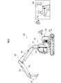
- Explanatory drawing which concerns on the structure of the peripheral monitoring apparatus for work machines as one Embodiment of this invention.
- Explanatory drawing about the 1st designated target space at the time of clockwise turning of an upper swing body Explanatory drawing about the 1st designated target space when the work machine retracts.
- Explanatory drawing about the azimuth angle of an object with respect to a work machine and the time change mode of an alarm sound.
- the explanatory view about the 1st function of the peripheral monitoring device for a work machine of 2nd Embodiment.
- Explanatory drawing about separation of objects around a work machine.
- Explanatory drawing about approach of an object around a work machine.
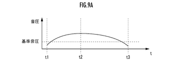
- Explanatory drawing about time change mode of acoustic frequency as an output mode of an alarm.
- the explanatory view about the time change mode of the sound pressure level as the output mode of an alarm.
- the explanatory view about the time change mode of the frequency of light as an output mode of an alarm.
- the explanatory view about the time change mode of the luminance as the output mode of an alarm.
- the peripheral monitoring device 100 for a work machine as an embodiment of the present invention shown in FIG. 1 monitors the situation around the work machine 200 and is applicable to an operator who operates the work machine 200 through the operation device 400. It is configured to output an alarm depending on the situation.
- the peripheral monitoring device 100 for a work machine includes a first detection element 111, a second detection element 112, a first control element 121, a second control element 122, and a plurality of output devices 130.
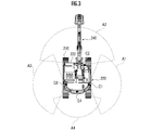
- the work machine 200 is, for example, a crawler excavator (construction machine), and as shown in FIGS. 2 and 3, the crawler type lower traveling body 210 and the lower traveling body 210 can be swiveled via a swivel mechanism 230.
- the upper swivel body 220 mounted on the vehicle is provided.
- a cab (driver's cab) 222 is provided on the front left side of the upper swing body 220.
- a work attachment 240 is provided at the front center portion of the upper swing body 220.
- the work attachment 240 is rotatably connected to the boom 241 undulatingly attached to the upper swing body 220, the arm 243 rotatably connected to the tip of the boom 241 and the tip of the arm 243. It is equipped with a bucket 245 and.
- the work attachment 240 is equipped with a boom cylinder 242, an arm cylinder 244, and a bucket cylinder 246, which are configured by a telescopic hydraulic cylinder.
- the boom cylinder 242 expands and contracts when the hydraulic oil is supplied, and is interposed between the boom 241 and the upper swing body 14 so as to rotate the boom 241 in the undulating direction.
- the arm cylinder 244 expands and contracts by receiving the supply of hydraulic oil and is interposed between the arm 243 and the boom 241 so as to rotate the arm 243 about a horizontal axis with respect to the boom 241.
- the bucket cylinder 246 expands and contracts when the hydraulic oil is supplied, and is interposed between the bucket 245 and the arm 243 so as to rotate the bucket 245 about a horizontal axis with respect to the arm 243.
- the operation device 400 includes a traveling operation device, a turning operation device, a boom operation device, an arm operation device, and a bucket operation device.
- Each operating device has an operating lever that receives a rotation operation.
- the operation lever (travel lever) of the travel operation device is operated to move the lower traveling body 210.
- the traveling lever may also serve as a traveling pedal.
- a traveling pedal fixed to the base or the lower end of the traveling lever may be provided.
- the operation lever (swivel lever) of the swivel operation device is operated to move the hydraulic swivel motor constituting the swivel mechanism 230.
- the operating lever (boom lever) of the boom operating device is operated to move the boom cylinder 242.
- the operating lever (arm lever) of the arm operating device is operated to move the arm cylinder 244.
- the operating lever (bucket lever) of the bucket operating device is operated to move the bucket cylinder 246.
- the operation device 400 includes a wireless communication device for wirelessly communicating with the actual machine side wireless communication device mounted on the work machine 200.
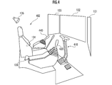
- Each operation lever constituting the operation device 400 is provided around the seat 402 on which the operator sits in the remote control room.
- a pair of left and right traveling levers 410 corresponding to the left and right crawlers may be arranged side by side in front of the seat 402.
- the seat 402 is in the form of a high back chair with armrests, but may be in any form in which the operator can sit, such as a low back chair without a headrest or a chair without a backrest.
- a robot is provided in the cab 222.
- the actual machine side operating lever may be directly operated by an operator existing in the cab 222. That is, the operation device 400 may be configured by the actual machine operation lever and a remote control valve that outputs a pilot pressure having a magnitude corresponding to the operation amount from a port corresponding to the operation direction. In this case, the operating device 400 may be configured to be able to communicate with the work machine 200 by a wired system instead of a wireless system.
- One operating lever may also serve as a plurality of operating levers.
- the right operating lever 420 provided in front of the right frame of the seat 402 shown in FIG. 4 functions as a boom lever when operated in the front-rear direction and is operated in the left-right direction. May function as a bucket lever.
- the left side operating lever 440 provided in front of the left side frame of the seat 402 shown in FIG. 4 functions as an arm lever when operated in the front-rear direction and is operated in the left-right direction. In some cases, it may function as a swivel lever.
- the lever pattern may be arbitrarily changed according to the operation instruction of the operator.
- the first detection element 111 detects the operating state of the operating device 400 for operating the work machine 200 by the operator.
- a sensor that outputs a signal according to the amount of deformation or displacement of the urging mechanism composed of a spring or an elastic member that acts to restore the operating lever to the original position and posture corresponding to the operation amount 0.
- the swivel lever was operated to swivel the upper swivel body 220 at a speed counterclockwise when viewed from above, and the boom, arm, bucket, etc. were operated.
- the first detection element 111 is configured by the estimation processing device and the estimation processing device.
- a pilot pressure sensor that outputs a signal according to the pilot pressure according to the operation amount of the actual machine side operation lever, and a speed that is counterclockwise when the upper swing body 220 is viewed from above based on the output signal of the pilot pressure sensor.
- the first detection element 111 may be configured by an arithmetic processing device that estimates that a boom, an arm, a bucket, or the like has been operated in addition to the operation of the swivel lever for swiveling.
- the second detection element 112 detects the position of an object existing around the work machine 200.
- the upper part is based on the output signals of the right side sensor C1, the front sensor C2, the left side sensor C3 and the rear sensor C4, and the sensors C1 to C4 arranged on the right side, the front side, the left side and the rear side of the upper swivel body 220, respectively. It is composed of an arithmetic processing device that specifies the real space position of an object in the working machine coordinate system (X, Y, Z) (see FIG. 3) whose position and posture are fixed with respect to the swivel body 220.
- Each of the sensors C1 to C4 is composed of, for example, a TOF type distance image sensor.
- each of the sensors C1 to C4 may be configured by an image pickup device capable of sensing an image whose pixel value is a physical quantity other than the distance such as brightness and color, such as a CCD camera.
- the three-dimensional position of the object existing at the pixel position in each sensor coordinate system is determined. Based on the three-dimensional position of the object in each sensor coordinate system, according to the coordinate conversion operator (rotation matrix or quaternion) representing the position and orientation of each sensor C1 to C4 in the work machine coordinate system, the object in the work machine coordinate system A three-dimensional position is required.
- Each of the sensors C1 to C4 has a substantially fan-shaped columnar right side detection target space A1, front detection target space A2, and left side detection extending to the right side, front, left side, and rear side of the upper swivel body 220 shown in FIG.
- a distance image of an object existing in each of the target space A3 and the rearward detection target space A4 is acquired. It is desirable that each of the right side detection target space A1 and the left side detection target space A3 and each of the front detection target space A2 and the rear detection target space A4 partially overlap, but they do not have to overlap.
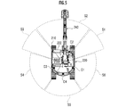
- each of the diagonally right front, front, diagonal left front, diagonal left rear, rear and diagonal right rear of the upper swivel body 220 is "plurality of target spaces”. Is defined as.
- Each extension mode (equation representing one or more boundary surfaces (planes or curved surfaces)) of the target spaces S1 to S6 in the work machine coordinate system (X, Y, Z) is stored in the storage device.
- Each of the upper surface and the lower surface of the substantially fan-shaped column corresponding to each space may be a horizontal plane (a plane parallel to the XY plane) or an inclined surface.
- the Z coordinate values of the centers of gravity of the upper and lower surfaces of the substantially fan-shaped columns corresponding to each space may be the same or different.
- Each of the plurality of output devices 130 corresponds to the respective orientations of the plurality of target spaces S1 to S3 with reference to the work machine 200, and is the remote control room (or the internal space of the cab 222) which is the operation space of the work machine 200. ), Right diagonally forward, front, left diagonally forward, left diagonally rearward, rearward, and right diagonally forward output device 131, forward output, respectively, based on the seat portion of the seat 402 (operator's whereabouts) on which the operator sits. It is arranged as a device 132, a left diagonal forward output device 133, a left diagonal rear output device 134, a rear output device 135, and a right diagonal rear output device 136, respectively.
- the output devices 131 to 133 are composed of, for example, an image output device such as a display and an audio output device such as a speaker, and output an alarm to the operator by image and audio.
- the output devices 134 to 136 are composed of, for example, a voice output device such as a speaker, and output an alarm by voice to the operator.
- the first control element 121 defines a first designated target space which is at least a part of a plurality of target spaces according to the operation mode of the work machine 200 predicted from the operation state detected by the first detection element 111. ..
- the second control element 122 When the position of the object detected by the second detection element 112 is included in the first designated target space defined by the first control element 121, the second control element 122 is among the plurality of output devices 130. When the position of the object detected by the second detection element 112 is on the first designated output device arranged in the operating space of the work machine 200 corresponding to the orientation of the first designated target space with respect to the work machine 200. Different alarms are output according to the change mode of the relative position of the object with respect to the work machine 200 determined by the sequence.
- Each of the first control element 121 and the second control element 122 is composed of a common or separate arithmetic processing unit (single-core processor or multi-core processor or a processor core constituting the same), and is composed of a storage device such as a memory.
- the necessary data and software are read, and the arithmetic processing result is output by executing the arithmetic processing according to the software for the data.
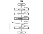
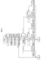
- the first detection element 111 detects the operating state of the operating device 400 for operating the work machine 200 by the operator (FIG. 6 / STEP 102). For example, it is detected that the swivel lever is operated to swivel the upper swivel body 220 at a speed counterclockwise or clockwise when viewed from above, depending on the amount of operation of the swivel lever.
- the operation mode of the work machine 200 is predicted by the first control element 121 based on the operation state detected by the first detection element 111 (FIG. 6 / STEP104).
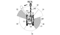
- the operation mode of the work machine 200 is that the upper swivel body 220 swivels at a speed counterclockwise when viewed from above according to the operating state of the swivel lever. Is expected as.
- the white arrow in FIG. 7B it is predicted that the upper swivel body 220 swivels at a speed that is clockwise when viewed from above as the operation mode of the work machine 200 according to the operating state of the swivel lever.
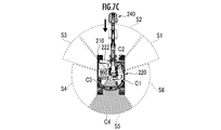
- the lower traveling body 210 retracts at a certain speed, and the work machine 200 retracts at a certain speed as a whole. It is predicted as the operation mode of the machine 200.
- the first control element 121 defines a part of the plurality of target spaces as the first designated target space based on the prediction result of the operation mode of the work machine 200 (FIG. 6 / STEP106). For example, when it is predicted that the upper swivel body 220 turns at a speed that is counterclockwise when viewed from above, among the plurality of target spaces S1 to S6, the left diagonally forward target space S3 and the right of the upper swivel body 220 At least one of the diagonally rearward target spaces S6 is defined as the first designated target space (see FIG. 7A).
- the upper swivel body 220 turns at a speed that is clockwise when viewed from above, at least of the right diagonal front target space S1 and the left diagonal rear target space S4 among the plurality of target spaces S1 to S6.
- One is defined as the first designated target space (see FIG. 7B).
- the rear target space S5 is defined as the first designated target space among the plurality of target spaces S1 to S6 (see FIG. 7C).
- all of a plurality of target spaces may be defined as the first designated target space.
- the second control element 122 determines whether or not the position of the object detected by the second detection element 112 is included in the first designated target space defined by the first control element 121 (FIG. 6 / STEP108).
- the output mode of the alarm is differentiated according to a difference in at least one of the relative distance of the object to the work machine 200, the rate of change of the relative distance, the relative direction of the object to the work machine 200, and the rate of change of the relative direction. Will be done.
- a plurality of concentric annular regions R11 to R14 with the swivel axis of the upper swivel body 220 as a reference point with respect to the lower traveling body 210 are defined.
- the level of the alarm output from the output device 130 or the first designated output device (easiness of recognition or alert power).
- the output mode of the alarm may be controlled so that
- a plurality of concentric rectangular annular regions R21 to R23 with the swivel axis of the upper swivel body 220 as a reference point with respect to the lower traveling body 210 are defined.
- a plurality of annular regions may be defined with the seat portion of the seat 402 (where the operator is located) on which the operator is seated as a reference point in the remote control room (or the internal space of the cab 222) which is the operating space of the work machine 200.
- the distance between the work machine 200 and the object Q gradually narrows, and the alarm level gradually increases (for example, from the lower limit value) accordingly.
- the distance between the work machine 200 and the object Q gradually increases, and the alarm level gradually decreases (for example, to the lower limit) accordingly.
- At least one element of the sound pressure, frequency and intermittent period of the alarm sound is controlled according to the mode of change of the interval.
- the sound pressure of the alarm is adjusted according to the width of the distance between the work machine 200 and the object Q. The size is set or controlled.
- the alarm sound of the reference frequency is set to be output when the object Q is located at the position corresponding to the intermediate interval between the maximum interval and the minimum interval between the reference point on the work machine 200 and the tip of the work attachment 240 or the position of the bucket 245. It may have been done.
- the alarm sound is set to be output in the reference cycle when the object Q is located at the position corresponding to the intermediate interval between the maximum interval and the minimum interval between the reference point on the work machine 200 and the tip of the work attachment 240 or the position of the bucket 245. It may have been done.
- an alarm may be output in the form of light emitted from a light emitting element or a light emitting device having a light emitting element such as an alarm lamp.
- a light emitting element or a light emitting device having a light emitting element such as an alarm lamp.
- at least one element of the wavelength (color), brightness (brightness), and blinking cycle (frequency of switching between light and dark) of the light emitted from the alarm lamp is changed according to the distance between the work machine 200 and the object Q. May be good.
- the relative velocity V of the object with respect to the work machine 200 is determined based on the displacement mode of the previous position of the object (detection position in the previous control cycle) or the position of the position over a predetermined period before the previous time and the current position of the object. Desired. Additional consideration is given to the relative change mode of one of the position and orientation of the work machine coordinate system in the world coordinate system according to the operating state of the work machine 200 such as the translation of the work machine 200 and the rotation of the upper swing body 220. Then, the relative velocity V of the object with respect to the work machine 200 may be obtained.
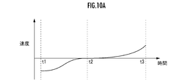
- the relative velocity of the object Q with respect to the work machine 200 changes as shown in FIG. 10A. That is, in the period [t1, t2], the relative velocity of the object Q with respect to the work machine 200 gradually decreases from a negative value (a state in which the object Q is approaching the work machine 200) to 0. To reach. In the period [t2, t3], the relative velocity of the object Q with respect to the work machine 200 gradually increases from 0 to a positive value (a state in which the object Q is moving away from the work machine 200).
- the alarm level decreases from the maximum value in the period [t1, t2], and the decrease rate gradually decreases, while the period [t2, t2].
- the alarm level decreases, and the rate of decrease gradually increases.
- the alarm level When the alarm level is expressed by sound pressure, as shown in FIG. 10B, the sound pressure drops from the maximum sound pressure to the reference sound pressure in the period [t1, t2], and the sound pressure decreases from the maximum sound pressure to the reference sound pressure in the period [t2, t3]. Then, the sound pressure drops from the reference sound pressure to the minimum sound pressure.
- the alarm level When the alarm level is expressed by the frequency of sound or the interval of intermittent sounds or the frequency of light or the blinking cycle of light, the alarm level may be adjusted in the same manner as described above.
- the alarm tones of the designated output devices corresponding to the target spaces S1 to S6 may be configured to be different.
- the first tone eg, beep
- the second tone when the object is located in the space on the left side of the work machine 200.
- whistle sound may be adopted as an alarm sound. It is possible to distinguish in which target space an object is located by timbre.
- a third tone may be assigned to the rear of the work machine 200.
- the timbre may be different according to the relative distance determined by the relative position of the object with respect to the work machine 200.
- the plurality of annular regions R11 to R14 are defined. It can be configured to add an alarm as the object exists in the annular space closer to the reference point in the space. For example, when an object is located outside R14, an alarm is given only with the first tone, and when an object approaches R13 inside, an alarm is given by superimposing a second tone in addition to the first tone.
- the degree of approach of an object can be alarmed by the degree of overlapping of tones.
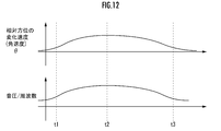
- the object Q moves along an arc centered on the turning axis of the upper turning body 220 with respect to the lower traveling body 210, it is relative to the relative distance between the work machine 200 and the object Q. Since the speed does not change, if the moving speed of the object Q is high, another means for emphasizing the alarm is required. In this case, the sound pressure or frequency of the alarm sound is adjusted to change as shown in the lower part of FIG. 12 according to the increase or decrease in the azimuth angular velocity of the object Q as shown in the upper part of FIG. May be good.
- At least a part of the plurality of target spaces is defined as the "first designated target space" according to the operation mode of the work machine 200 predicted based on the operation state of the operation device 400 of the work machine 200 (FIG. 6). / STEP102 to STEP106, see FIGS. 7A to 7C).
- an alarm is output by the first designated output device, and the alarm is differentiated according to the change mode of the relative position between the work machine 200 and the object.
- the first designated output device is arranged in an orientation corresponding to the orientation of the first designated target space with respect to the work machine 200 with reference to the operator's location (position of the seat 402) in the operating space of the work machine 200. (See FIG. 4).
- the work machine 200 when an operator seated on the seat 402 operates the operation device 400 in the operating space of the work machine 200 and an alarm is output by the first designated output device, the work machine 200 according to the operation state
- the operator can intuitively recognize the existence of an object in the direction of operation.
- the first designated output device is made to output an alarm in a different manner according to the difference in the mode of changing the interval between the work machine 200 and the object Q, which is determined according to the relative position between the work machine 200 and the object Q.
- the operator can intuitively understand the change mode of the distance between the work machine 200 and the object, for example, whether it is relatively close or far away, according to the difference in the alarm output by the first designated output device. Can be recognized by.
- the alarm level can be set to increase.
- the alarm level can be set to be lowered.
- the peripheral monitoring device 100 for a work machine having the configuration whether the work machine 200 and the object are relatively close to each other or far from each other according to the difference in the change mode of the alarm output by the first designated output device.
- the difference can be intuitively recognized by the operator.
- the alarm level can be set to increase.
- the alarm level can be set to be lowered.
- the operator intuitively understands the difference in the relative speed of the object with respect to the work machine 200 according to the difference in the mode of change of the sound as an alarm output by the first designated output device. Can be recognized as a target.
- one type of alarm is given according to sound pressure, frequency, or interval, and in addition, another type of alarm is given depending on the wavelength, brightness, and period of the warning light.
- a plurality of alarms may be issued by using a plurality of elements of the alarm means.
- the sound pressure of the alarm sound is used to warn the relative distance of the object to the work machine 200, and the frequency of the alarm sound is used to warn the relative speed of the object.
- the operator can recognize a plurality of alarms with only one alarm (alarm sound).
- Another alarm means (alarm light) can be assigned another alarm. The association between the alarm element of the alarm means and the content of the alarm can be appropriately determined.
- the alarm is configured to be continuously changed according to the distance and speed, but it does not have to be continuous.
- the alarm may be limited to some simple ones.
- the first detection element 111 detects the operating state of the operating device 400 for operating the work machine 200 by the operator (FIG. 13 / STEP202). For example, it is detected that the swivel lever is operated to swivel the upper swivel body 220 at a speed counterclockwise or clockwise when viewed from above, depending on the amount of operation of the swivel lever.
- the operation mode of the work machine 200 is predicted by the first control element 121 based on the operation state detected by the first detection element 111 (FIG. 13 / STEP204). For example, depending on the operating state of the swivel lever, the operation mode of the work machine 200 is predicted as in the example of the first embodiment (see FIGS. 7A to 7C).
- the first control element 121 determines the first designated target space, which is at least a part of the plurality of target spaces, based on the prediction result of the operation mode of the work machine 200 (FIG. 13 / STEP206). For example, as in the example of the first embodiment, at least one target space among the plurality of target spaces S1 to S6 is defined as the first designated target space (see FIGS. 7A to 7C).
- the second control element 122 determines whether or not the position of the object detected by the second detection element 112 is included in the first designated target space defined by the first control element 121 (FIG. 13 / STEP208).
- the relative velocity V of the object with respect to the work machine 200 is obtained based on the displacement mode of the previous position of the object (detection position in the previous control cycle) or the position of the position over a predetermined period before the previous time and the current position of the object. .. Additional consideration is given to the relative change mode of one of the positions and orientations of the work machine coordinate system in the world coordinate system according to the operating state of the work machine 200 such as the translation of the work machine 200 and the rotation of the upper swing body 220. Then, the relative velocity V of the object with respect to the work machine 200 may be obtained.
- the second control element 122 determines that the second of the plurality of output devices 130 is 1
- the alarm of mode "0" is output through the designated output device (FIG. 13 / STEP212).
- the "first designated output device” is an output device arranged in the operating space of the work machine 200 corresponding to the orientation of the first designated target space with respect to the work machine 200 among the plurality of output devices 130. .. For example, when the first designated target space is the right diagonal rear target space S6, the right diagonal rear output device 136 outputs an alarm as the first designated output device (see FIGS. 4 and 5).
- the left diagonal rear output device 134 When the first designated target space is the left diagonal rear target space S4, the left diagonal rear output device 134 outputs an alarm as the first designated output device.
- the rear output device 135 When the first designated target space is the rear target space S5, the rear output device 135 outputs an alarm as the first designated output device.
- of the relative velocity V is V by the second control element 122. It is determined whether or not it is less than 1 (> ⁇ 2 ) (Fig. 13 / STEP214). When the determination result is affirmative (FIG. 13 / STEP214 ... YES), the second control element 122 outputs the alarm of the mode "1-1" through the first designated output device (FIG. 13 / STEP216). If the determination result is negative (FIG. 13 / STEP214 ... NO), the second control element 122 outputs the alarm of the mode "1-2" through the first designated output device (FIG. 13 / STEP218).
- of the relative velocity V is determined by the second control element 122. It is determined whether or not it is less than V 2 (> ⁇ 1 ) (Fig. 13 / STEP220).
- the second control element 122 outputs the alarm of the mode "2-1" through the first designated output device (FIG. 13 / STEP222). If the determination result is negative (FIG. 13 / STEP220 ... NO), the second control element 122 outputs the alarm of aspect "2-2" through the first designated output device (FIG. 13 / STEP224).
- Aspects “0”, Aspect “1-1”, Aspect “1-2”, Aspect “2-1” and Aspect “2-2" are different from each other.
- the time t corresponds to, for example, a warning cycle, and an alarm is issued at each time t.
- the acoustic frequency may be gradually increased in the case of emphasis and gradually decreased in the case of weakness in the alarm cycle.
- the aspect "0", the aspect "1-1”, the aspect “1-2”, the aspect “2-1” and the aspect “2-2” The alarm changes to either.
- the modes “1-1” and “1-2” and the modes “2-1” and “2-2" correspond to two types of alarm levels, but three or more types of alarms are used. It may correspond to the level.
- Perspective speed can be alerted more finely than expressed by two types of alarms. Not limited to the frequency of the alarm sound, the sound pressure, the interval, the wavelength, the brightness, the period, etc. of the warning light may be similarly set to several types of alarms.
- the alarm is simplified only in the mode "0", the mode "1-1", the mode "1-2", the mode "2-1" and the mode "2-2". Can be converted. The operator can easily grasp the change mode of the distance between the work machine 200 and the object by the simplified alarm.
- the position of the object is changed from the first designated target space among the plurality of target spaces by the second control element 122. It is determined whether or not the object is heading toward the second designated target space, which is the target space (whether or not the extension line of the movement vector of the object overlaps with another target space) (FIG. 14 / STEP226).
- the second control element 122 defines the other target space as the second designated target space (FIG. 14 / STEP228). For example, when an object existing in the rear target space S5 as the first designated target space is moving toward the right diagonal rear target space S6, the right diagonal rear target space S6 is defined as the second designated target space.
- the second designated output device is an output device arranged in the operating space corresponding to the orientation of the second designated target space with respect to the work machine 200.
- the right diagonal rear output device 136 outputs a secondary alarm as the second designated output device.
- aspects p-1 and p-2 are similar to the relationship between aspects 1-1 and 1-2 or the relationship between aspects 2-1 and 2-2 (see FIGS. 16A to 16D).
- At least a part of the plurality of target spaces is defined as the "first designated target space" according to the operation mode of the work machine 200 predicted based on the operation state of the operation device 400 of the work machine 200 (FIG. 13). / STEP202-206, see FIGS. 7A-7C).
- the operation of the work machine 200 is a concept that includes not only the overall operation of the work machine 200 but also the operation of a moving portion that is a part thereof.
- the first designated output device is arranged in an orientation corresponding to the orientation of the first designated target space with respect to the work machine 200 with reference to the operator's location (position of the seat 402) in the operating space of the work machine 200. (See FIG. 4).
- the "azimuth" is specified not only by a single azimuth angle but also by an azimuth angle range, and may be further specified by an elevation angle range.
- the second control element 122 gives an alarm to the first designated output device in a different manner according to the difference in the change mode of the distance between the work machine 200 and the object Q, which is determined according to the relative position between the work machine 200 and the object Q.
- Output see FIGS. 16A to 16D.
- the operator can intuitively understand the change mode of the distance between the work machine 200 and the object, for example, whether it is relatively close or far away, according to the difference in the alarm output by the first designated output device. Can be recognized (see FIGS. 15A and 15B).
- the second control element 122 causes the first designated output device to output an alarm to be emphasized when the distance between the work machine 200 and the object is small, and when the distance between the work machine 200 and the object is large,
- the weak alarm is output to the first designated output device.
- a sound having a relatively high frequency is output as an alarm to the first designated output device (FIG. 13 / STEP222, 224, FIG. 16A / f 2-). See 1 (t) and f 2-2 (t)).
- a sound having a relatively low frequency is output as an alarm to the first designated output device (FIG. 13 / STEP216, 218, FIG.
- the operator can intuitively recognize the difference in whether the work machine 200 and the object are relatively close to each other or far from each other according to the difference in the change mode of the alarm output by the first designated output device. Can be done. That is, the difference in whether the work machine 200 and the object are relatively close to each other or far from each other according to the difference in the frequency change mode such as the Doppler effect of the sound as an alarm output by the first designated output device. Can be intuitively recognized by the operator.
- the second control element 122 adjusts so that the greater the rate of change in the distance between the work machine and the object, the greater the rate of change in the emphasis or weakness of the alarm output by the first designated output device.
- the greater the rate of change in the distance between the work machine 200 and the object the greater the rate of change in the frequency of the sound as an alarm output by the first designated output device (FIGS. 13 / STEP214,216, 218).
- STEP220, 222,224 Fig. 16A / f 1-1 (t), f 1-2 (t), f 2-1 (t), f 2-2 (t)).
- the operator can intuitively recognize the level of change in the interval between the work machine and the object according to the level of change in the alarm output by the first designated output device.
- an alarm is output to the second designated output device in addition to the first designated output device.
- the rear output is output.
- the primary alarm is output by the device 133
- the secondary alarm is output by the right output device 131 after the output of the primary alarm is started, before the output of the primary alarm is completed, or after the output of the primary alarm is completed.
- the second control element 122 changes the ratio of the period for causing the second designated output device to output the alarm to the period for causing the first designated output device to output the alarm according to the speed of movement of the object. May be good.
- the first detection element 111 is operated from the non-interacting state (for example, the state in which the operator is not holding or touching the operating lever) between the operator and the operating device 400 as the operating state by the operator of the operating device 400. For example, a transition to a state in which the operator is holding or touching the operation lever), or a state in which the operation device 400 is operated by the operator in the dead zone may be detected. If a non-zero operating amount of the operating lever is detected, but its magnitude is less than the threshold value, the transition from the non-interacting state between the operator and the operating device 400 to the interacting state, or the operator 400 operating device 400 May be detected that is being operated in the dead zone. Further, on the condition that the state is detected by the first detection element 111, the output device 130 may be controlled by the second output device 122 to a state in which the alarm output is possible.
- the non-interacting state for example, the state in which the operator is not holding or touching the operating lever
- the output device 130 may be controlled by the second output device 122 to a state
- the peripheral monitoring device 100 for a work machine having the configuration it is highly probable that the operator intends to operate the work machine 200, but the operation device by the operator is in the initial stage of operation when the work machine 200 has not yet started operation.
- the operator is made to intuitively recognize that the object exists in the operating direction of the work machine 200 according to the operation of the 400, and the relative position of the work machine 200 and the object is changed according to the difference in the alarm. The operator can intuitively recognize the difference in mode.
- a plurality of concentric annular regions R11 to R14 with the swivel axis of the upper swivel body 220 as a reference point with respect to the lower traveling body 210 may be defined.
- a plurality of concentric rectangular annular regions R21 to R23 with the swivel axis of the upper swivel body 220 as a reference point with respect to the lower traveling body 210 may be defined.
- a plurality of annular regions may be defined with the seat portion of the seat 402 (where the operator is located) on which the operator is seated as a reference point in the remote control room (or the internal space of the cab 222) which is the operating space of the work machine 200.
- the second control element 122 may output the alarm to the second designated output device after the first designated output device outputs the alarm.
- one of the plurality of output devices 130 corresponds to the arrangement orientation in the operating space of one output device (first designated output device) to which an alarm is output first. From the target space (first designated target space) to another target space (second designated target space) corresponding to the arrangement orientation in the operating space of the other output device (second designated output device) to which the alarm was output later.
- first designated target space first designated target space
- second designated target space second designated target space
- the second control element 122 may change the ratio of the period for causing the second designated output device to output the alarm to the period for causing the first designated output device to output the alarm according to the speed of movement of the object.
- the object is moving from one target space (first designated target space) to another target space (second designated target space) as described above.
- first designated target space first designated target space
- second designated target space second designated target space
- the operator can intuitively recognize the high or low of the moving speed of the object according to the ratio of the alarm output period by the first designated output device and the alarm output period by the second designated output device.
- the second control element 122 is a plurality of elements constituting an alarm sound as an alarm according to the difference between the relative position between the work machine 200 and the object and the change mode of the distance between the work machine 200 and the object. It is preferable that the first designated output device outputs the alarm, which is differentiated in a different manner.
- the relative position of the object with the work machine 200 and the change mode thereof can be simultaneously expressed by one alarm means, and the operator can be intuitively recognized.
Landscapes
- Engineering & Computer Science (AREA)
- Mining & Mineral Resources (AREA)
- Civil Engineering (AREA)
- General Engineering & Computer Science (AREA)
- Structural Engineering (AREA)
- Physics & Mathematics (AREA)
- General Physics & Mathematics (AREA)
- Mechanical Engineering (AREA)
- Electromagnetism (AREA)
- Component Parts Of Construction Machinery (AREA)
- Emergency Alarm Devices (AREA)
- Traffic Control Systems (AREA)
Abstract
作業機械のオペレータに対して、当該作業機械の周辺における人等の物体の動きを、作業機械の操作態様を決定する観点から適当なタイミングで、直感的に認識させることができる装置を提供する。発明の作業機械用周辺監視装置(100)によれば、作業機械(200)の操作装置(400)のオペレータによる操作状態に基づいて予測される作業機械(200)の動作態様に応じて、複数の対象空間(S1)~(S6)の少なくとも一部が「第1指定対象空間」として定められる。物体の位置が第1指定対象空間に含まれている場合、作業機械(200)の運転空間においてオペレータの居場所を基準として、作業機械(200)を基準とする第1指定対象空間の方位に対応する方位に配置されている第1指定出力装置により警報が出力される。当該警報が、作業機械(200)と物体との相対位置の変化態様に応じて差異化される。
Description
本発明は、作業機械の周辺を監視するための装置に関する。
作業機械の周囲に存在する人の位置を作業機械のオペレータが直感的に把握できるようにするため、一の監視空間(例えば作業機械の右側)に人が存在すると判定された場合に当該一の監視空間に対応する一の警報出力部(例えばキャブ内の右側警報出力部)から警報を出力させ、他の監視空間(例えば作業機械の後方)に人が存在すると判定された場合に当該他の監視空間に対応する他の警報出力部(例えばキャブ内の後方警報出力部)から警報を出力させる技術が提案されている(例えば、特許文献1参照)。
しかし、作業機械のオペレータにとっては、作業機械の適当な操作態様を決定する等の観点から、作業機械の周辺における人等の物体の有無のみならず、当該物体の動きに関しても直感的に把握できることが望ましい。
そこで、本発明は、作業機械のオペレータに対して、当該作業機械の周辺における人等の物体の動きを、作業機械の操作態様を決定する観点から適当なタイミングで、直感的に認識させることができる装置を提供することを目的とする。
本発明の作業機械用周辺監視装置は、オペレータによる作業機械を動作させるための操作装置の操作状態を検知する第1検知要素と、前記作業機械の周囲に存在する物体の位置を検知する第2検知要素と、前記作業機械を基準として複数の対象空間のそれぞれの方位に対応するように、前記作業機械の運転空間においてオペレータの居場所を基準として複数の方位のそれぞれに配置された、当該オペレータに対して警報を出力する複数の出力装置と、前記第1検知要素により検知された前記操作状態から予測される前記作業機械の動作態様に応じて、前記複数の対象空間のうち少なくとも一部である第1指定対象空間を定める第1制御要素と、前記第1制御要素により定められた前記第1指定対象空間に、前記第2検知要素により検知された前記物体の位置が含まれている場合、前記複数の出力装置のうち、前記作業機械を基準とした前記第1指定対象空間の方位に対応して前記作業機械の運転空間に配置されている第1指定出力装置に、前記第2検知要素により検知された前記物体の位置の時系列により定まる前記作業機械に対する前記物体の相対位置の変化態様に応じて異なる警報を出力させる第2制御要素と、を備えていることを特徴とする。
(構成)
図1に示されている本発明の一実施形態としての作業機械用周辺監視装置100は、作業機械200の周辺の状況を監視し、操作装置400を通じて作業機械200を操作するオペレータに対して当該状況に応じて警報を出力するように構成されている。作業機械用周辺監視装置100は、第1検知要素111と、第2検知要素112と、第1制御要素121と、第2制御要素122と、複数の出力装置130と、を備えている。
図1に示されている本発明の一実施形態としての作業機械用周辺監視装置100は、作業機械200の周辺の状況を監視し、操作装置400を通じて作業機械200を操作するオペレータに対して当該状況に応じて警報を出力するように構成されている。作業機械用周辺監視装置100は、第1検知要素111と、第2検知要素112と、第1制御要素121と、第2制御要素122と、複数の出力装置130と、を備えている。
作業機械200は、例えばクローラショベル(建設機械)であり、図2および図3に示されているように、クローラ式の下部走行体210と、下部走行体210に旋回機構230を介して旋回可能に搭載されている上部旋回体220と、を備えている。上部旋回体220の前方左側部にはキャブ(運転室)222が設けられている。上部旋回体220の前方中央部には作業アタッチメント240が設けられている。
作業アタッチメント240は、上部旋回体220に起伏可能に装着されているブーム241と、ブーム241の先端に回動可能に連結されているアーム243と、アーム243の先端に回動可能に連結されているバケット245と、を備えている。作業アタッチメント240には、伸縮可能な油圧シリンダにより構成されているブームシリンダ242、アームシリンダ244およびバケットシリンダ246が装着されている。
ブームシリンダ242は、作動油の供給を受けることにより伸縮してブーム241を起伏方向に回動させるように当該ブーム241と上部旋回体14との間に介在する。アームシリンダ244は、作動油の供給を受けることにより伸縮してアーム243をブーム241に対して水平軸回りに回動させるように当該アーム243と当該ブーム241との間に介在する。バケットシリンダ246は、作動油の供給を受けることにより伸縮してバケット245をアーム243に対して水平軸回りに回動させるように当該バケット245と当該アーム243との間に介在する。
操作装置400には、走行用操作装置と、旋回用操作装置と、ブーム用操作装置と、アーム用操作装置と、バケット用操作装置と、が含まれている。各操作装置は、回動操作を受ける操作レバーを有している。走行用操作装置の操作レバー(走行レバー)は、下部走行体210を動かすために操作される。走行レバーは、走行ペダルを兼ねていてもよい。例えば、走行レバーの基部または下端部に固定されている走行ペダルが設けられていてもよい。旋回用操作装置の操作レバー(旋回レバー)は、旋回機構230を構成する油圧式の旋回モータを動かすために操作される。ブーム用操作装置の操作レバー(ブームレバー)は、ブームシリンダ242を動かすために操作される。アーム用操作装置の操作レバー(アームレバー)はアームシリンダ244を動かすために操作される。バケット用操作装置の操作レバー(バケットレバー)はバケットシリンダ246を動かすために操作される。操作装置400は、作業機械200に搭載されている実機側無線通信装置と無線方式で通信するための無線通信装置を備えている。
操作装置400を構成する各操作レバーは、遠隔操作室においてオペレータが着座するシート402の周囲に設けられている。例えば、図4に示されているように、シート402の前方に左右のクローラに応じた左右一対の走行レバー410が左右横並びに配置されていてもよい。シート402は、アームレスト付きのハイバックチェアのような形態であるが、ヘッドレストがないローバックチェアのような形態、または、背もたれがないチェアのような形態など、オペレータが着座できる任意の形態でもよい。
遠隔操作室に設けられている操作レバーに対応する実機側操作レバーと、遠隔操作室から各操作レバーの操作態様に応じた信号を受信し、当該受信信号に基づいて実機操作レバーを動かす駆動機構またはロボットと、がキャブ222に設けられている。実機側操作レバーが、キャブ222に存在するオペレータにより直接的に操作されてもよい。すなわち、当該実機操作レバーと、その操作量に対応した大きさのパイロット圧を操作方向に対応したポートから出力するリモコン弁と、により操作装置400が構成されていてもよい。この場合、操作装置400は無線方式ではなく有線方式で作業機械200と通信可能に構成されていてもよい。
一の操作レバーが複数の操作レバーを兼ねていてもよい。例えば、図4に示されているシート402の右側フレームの前方に設けられている右側操作レバー420が、前後方向に操作された場合にブームレバーとして機能し、かつ、左右方向に操作された場合にバケットレバーとして機能してもよい。同様に、図4に示されているシート402の左側フレームの前方に設けられている左側操作レバー440が、前後方向に操作された場合にアームレバーとして機能し、かつ、左右方向に操作された場合に旋回レバーとして機能してもよい。レバーパターンは、オペレータの操作指示によって任意に変更されてもよい。
第1検知要素111は、オペレータによる作業機械200を動作させるための操作装置400の操作状態を検知する。例えば、操作レバーを操作量0に対応する元の位置および姿勢に復元させるように作用するばねまたは弾性部材により構成される付勢機構の変形量または変位量に応じた信号を出力するセンサと、当該センサの出力信号に基づいて上部旋回体220を上方から見て反時計回りにある速度で旋回させるために旋回レバーが操作されたことのほか、ブーム、アームおよびバケット等が操作されたことを推定する演算処理装置と、により第1検知要素111が構成されている。
実機側操作レバーの操作量に応じたパイロット圧に応じた信号を出力するパイロット圧センサと、当該パイロット圧センサの出力信号に基づいて上部旋回体220を上方から見て反時計回りにある速度で旋回させるために旋回レバーが操作されたことのほか、ブーム、アームおよびバケット等が操作されたことを推定する演算処理装置と、により第1検知要素111が構成されていてもよい。
第2検知要素112は、作業機械200の周囲に存在する物体の位置を検知する。上部旋回体220の右側、前側、左側および後側のそれぞれに配置された右側センサC1、前方センサC2、左側センサC3および後方センサC4、ならびに、センサC1~C4のそれぞれによる出力信号に基づき、上部旋回体220に対して位置および姿勢が固定されている作業機械座標系(X,Y,Z)(図3参照)における、物体の実空間位置を特定する演算処理装置により構成されている。センサC1~C4のそれぞれは、例えばTOF方式の距離画像センサにより構成されている。距離画像センサに加えて、CCDカメラなど、輝度、色彩などの距離以外の物理量を画素値とする画像をセンシング可能な撮像装置によりセンサC1~C4のそれぞれが構成されていてもよい。
各センサC1~C4により得られた3次元距離画像における画素位置および画素値(距離)に基づき、当該画素位置に存在する物体の各センサ座標系における3次元位置が定められる。各センサ座標系における物体の3次元位置に基づき、作業機械座標系における各センサC1~C4の位置および姿勢を表わす座標変換演算子(回転行列またはクォータニオン)にしたがって、作業機械座標系における当該物体の3次元位置が求められる。
センサC1~C4のそれぞれは、図3に示されている上部旋回体220の右側、前方、左側および後方のそれぞれに広がる、略扇形柱状の右側検知対象空間A1、前方検知対象空間A2、左側検知対象空間A3および後方検知対象空間A4のそれぞれに存在する物体の距離画像を取得する。右側検知対象空間A1および左側検知対象空間A3のそれぞれと、前方検知対象空間A2および後方検知対象空間A4のそれぞれとは部分的に重複させることが望ましいが、重複していなくてもよい。
例えば、上部旋回体220がZ軸回りに反時計回りに旋回する場合、上部旋回体220の左斜め前方および右斜め後方の空間に存在している物体との接触可能性が高くなる(図8A参照)。上部旋回体220がZ軸回りに時計回りに旋回する場合、上部旋回体220の右斜め前方および左斜め後方の空間に存在している物体との接触可能性が高くなる(図8B参照)。作業機械200が後退する場合、作業機械200の後方の空間に存在している物体との接触可能性が高くなる(図8C参照)。
これらのことに鑑みて、本実施形態では、図5に示されているように、上部旋回体220の右斜め前方、前方、左斜め前方、左斜め後方、後方および右斜め後方のそれぞれを基準として広がる略扇形柱状の右斜め前方対象空間S1、前方対象空間S2、左斜め前方対象空間S3、左斜め後方対象空間S4、後方対象空間S5および右斜め後方対象空間S6が「複数の対象空間」として定義されている。作業機械座標系(X,Y,Z)における対象空間S1~S6のそれぞれの延在態様(一または複数の境界面(平面または曲面)を表わす方程式)は記憶装置に保存されている。各空間に対応する略扇形柱の上面および下面のそれぞれは水平面(X-Y平面に平行な平面)であってもよく傾斜面であってもよい。各空間に対応する略扇形柱の上面および下面のそれぞれの重心のZ座標値は同一であってもよく異なっていてもよい。
複数の出力装置130のそれぞれは、作業機械200を基準として複数の対象空間S1~S3のそれぞれの方位に対応するように、作業機械200の運転空間である遠隔操作室(またはキャブ222の内部空間)においてオペレータが着座するシート402(オペレータの居場所)の座部を基準として右斜め前方、前方、左斜め前方、左斜め後方、後方および右斜め後方のそれぞれに右斜め前方出力装置131、前方出力装置132、左斜め前方出力装置133、左斜め後方出力装置134、後方出力装置135および右斜め後方出力装置136のそれぞれとして配置されている。出力装置131~133は、例えば、ディスプレイなどの画像出力装置と、スピーカなどの音声出力装置と、により構成され、オペレータに対して画像および音声により警報を出力する。出力装置134~136は、例えば、スピーカなどの音声出力装置により構成され、オペレータに対して音声により警報を出力する。
第1制御要素121は、第1検知要素111により検知された操作状態から予測される作業機械200の動作態様に応じて、複数の対象空間のうち少なくとも一部である第1指定対象空間を定める。
第2制御要素122は、第1制御要素121により定められた第1指定対象空間に、第2検知要素112により検知された物体の位置が含まれている場合、複数の出力装置130のうち、作業機械200を基準とした第1指定対象空間の方位に対応して作業機械200の運転空間に配置されている第1指定出力装置に、第2検知要素112により検知された物体の位置の時系列により定まる作業機械200に対する物体の相対位置の変化態様に応じて異なる警報を出力させる。
第1制御要素121および第2制御要素122のそれぞれは、共通のまたは別個の演算処理装置(シングルコアプロセッサまたはマルチコアプロセッサもしくはこれを構成するプロセッサコア)により構成されており、メモリなどの記憶装置から必要なデータおよびソフトウェアを読み取り、当該データを対象として当該ソフトウェアにしたがった演算処理を実行することにより当該演算処理結果を出力する。
(機能)
前記構成の作業機械用周辺監視装置100の機能について説明する。
前記構成の作業機械用周辺監視装置100の機能について説明する。
(第1実施形態)
第1検知要素111により、オペレータによる作業機械200を動作させるための操作装置400の操作状態が検知される(図6/STEP102)。例えば、旋回レバーの操作量に応じて、上部旋回体220を上方から見て反時計回りまたは時計回りにある速度で旋回させるために旋回レバーが操作されたことが検知される。
第1検知要素111により、オペレータによる作業機械200を動作させるための操作装置400の操作状態が検知される(図6/STEP102)。例えば、旋回レバーの操作量に応じて、上部旋回体220を上方から見て反時計回りまたは時計回りにある速度で旋回させるために旋回レバーが操作されたことが検知される。
第1制御要素121により、第1検知要素111により検知された操作状態に基づき、作業機械200の動作態様が予測される(図6/STEP104)。例えば、旋回レバーの操作状態に応じて、図7Aに白矢印で示されているように、上部旋回体220が上方から見て反時計回りにある速度で旋回することが作業機械200の動作態様として予測される。旋回レバーの操作状態に応じて、図7Bに白矢印で示されているように、上部旋回体220が上方から見て時計回りにある速度で旋回することが作業機械200の動作態様として予測される。走行レバーの操作状態に応じて、図7Cに白矢印で示されているように、下部走行体210がある速度で後退すること、ひいては作業機械200が全体的にある速度で後退することが作業機械200の動作態様として予測される。
第1制御要素121により、作業機械200の動作態様の予測結果に基づき、複数の対象空間のうちの一部が第1指定対象空間として定められる(図6/STEP106)。例えば、上部旋回体220が上方から見て反時計回りにある速度で旋回することが予測された場合、複数の対象空間S1~S6のうち、上部旋回体220の左斜め前方対象空間S3および右斜め後方対象空間S6のうち少なくとも一方が第1指定対象空間として定められる(図7A参照)。上部旋回体220が上方から見て時計回りにある速度で旋回することが予測された場合、複数の対象空間S1~S6のうち、右斜め前方対象空間S1および左斜め後方対象空間S4のうち少なくとも一方が第1指定対象空間として定められる(図7B参照)。作業機械200がある速度で後退することが予測された場合、複数の対象空間S1~S6のうち、後方対象空間S5が第1指定対象空間として定められる(図7C参照)。なお、複数の対象空間の全てが第1指定対象空間として定められてもよい。
第2制御要素122により、第1制御要素121により定められた第1指定対象空間に、第2検知要素112により検知された物体の位置が含まれているか否かが判定される(図6/STEP108)。
第1指定対象空間に物体の位置が含まれていないと判定された場合(図6/STEP108‥NO)、今回制御周期における一連の処理が終了する。第1指定対象空間に物体の位置が含まれていると判定された場合(図6/STEP108‥YES)、第1指定出力装置に警報を出力させる(図6/STEP110)。
作業機械200に対する物体の相対距離、当該相対距離の変化速度、作業機械200に対する物体の相対方位、および、当該相対方位の変化速度のうち少なくとも1つの相違に応じて当該警報の出力態様が差異化される。
図8Aに示されているように、下部走行体210に対する上部旋回体220の旋回軸線を基準点とする同心円環状の複数の環状領域R11~R14が定義されている。当該複数の環状領域R11~R14のうち物体が存在する環状領域が基準点に近い場合ほど、出力装置130または第1指定出力装置から出力される警報のレベル(認識されやすさまたは注意喚起力)が高くなるように、当該警報の出力態様が制御されてもよい。
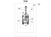
例えば、図8Bに示されているように、下部走行体210に対する上部旋回体220の旋回軸線を基準点とする同心矩形環状の複数の環状領域R21~R23が定義されていてる。作業機械200の運転空間である遠隔操作室(またはキャブ222の内部空間)においてオペレータが着座するシート402(オペレータの居場所)の座部を基準点として複数の環状領域が定義されていてもよい。
ここで、物体Qが時刻t=t1において環状領域R14に含まれる作業機械200の右後方位置にあり、時刻t=t2において環状領域R13に含まれる作業機械200の後方位置にあり、時刻t=t3において環状領域R14に含まれる作業機械200の左後方位置にあるように移動した場合について考察する(図8A/矢印Q(t=t1)→Q(t=t2)および矢印Q(t=t2)→Q(t=t3)参照)。すなわち、期間t=t1~t2において、作業機械200と物体Qとの間隔が徐々に狭まり、期間t=t2~t3において、作業機械200と物体Qとの間隔が徐々に広がる。
この場合、期間t=t1~t2において、作業機械200と物体Qとの間隔が徐々に狭まり、これに応じて警報レベルが(例えば下限値から)徐々に増加する。その一方、期間t=t2~t3において、作業機械200と物体Qとの間隔が徐々に広がり、これに応じて警報レベルが徐々に(例えば下限値まで)低下する。警報音の音圧、周波数および断続周期のうち少なくとも1つの要素が、当該間隔の変化態様に応じて制御される。
警報レベルの高低が「音圧(または警報音の音量)」の高低により表現される場合、図9Aに示されているように、警報の音圧が期間t=t1~t2において途中で基準音圧を超えるように徐々に上昇する一方、期間t=t2~t3において途中で基準音圧を下回るように徐々に低下する。警報の音圧の高低と、作業機械200に対する物体Qの相対位置との相関関係をオペレータに直感的に認識させるため、作業機械200と物体Qとの間隔の広狭に応じて警報の音圧の大小が設定または制御されている。作業機械200における基準点と作業アタッチメント240の先端またはバケット245の位置との最大間隔および最小間隔の中間間隔に応じた位置に物体Qがある場合に警報が基準音圧で出力されるように設定されていてもよい。
警報レベルの高低が「警報音の周波数」の高低により表現される場合、図9Bに示されているように、警報音の周波数が期間t=t1~t2において途中で基準周波数を超えるように徐々に上昇する一方、期間t=t2~t3において途中で基準周波数を下回るように徐々に低下する)。作業機械200における基準点と作業アタッチメント240の先端またはバケット245の位置との最大間隔および最小間隔の中間間隔に応じた位置に物体Qがある場合に基準周波数の警報音が出力されるように設定されていてもよい。
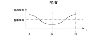
警報レベルの高低が「警報音の断続周期」の長短により表現される場合、図9Cに示されているように、警報音の断続周期が期間t=t1~t2において途中で基準周期を下回るように徐々に短くなる一方、期間t=t2~t3において途中で基準周期を超えるように徐々に長くなる」。作業機械200における基準点と作業アタッチメント240の先端またはバケット245の位置との最大間隔および最小間隔の中間間隔に応じた位置に物体Qがある場合に警報音が基準周期で出力されるように設定されていてもよい。
警報音に加えてまたは代えて、警報ランプ等、発光素子または発光素子を有する発光装置から発せられる光の形態で警報が出力されてもよい。例えば、警報ランプから発せられる光の波長(色)、輝度(明るさ)および点滅周期(明暗の切り替わり頻度)のうち少なくとも1つの要素が作業機械200と物体Qとの間隔に応じて変化させてもよい。
また、物体の前回位置(前回制御周期における検知位置)または前回以前の所定期間にわたる位置の変位態様と、物体の今回位置と、の変位態様に基づき、作業機械200に対する当該物体の相対速度Vが求められる。作業機械200の並進および上部旋回体220の旋回などの作業機械200の動作状態に応じた、世界座標系における作業機械座標系の位置および姿勢のうち一方の相対的な変化態様が付加的に勘案されたうえで、作業機械200に対する当該物体の相対速度Vが求められてもよい。
図8Aに例示されているように物体Qが移動する場合、図10Aに示されているように作業機械200に対する物体Qの相対速度が変化する。すなわち、期間[t1,t2]において、作業機械200に対する物体Qの相対速度は、負値(物体Qが作業機械200に対して接近している状態)から徐々にその大きさが小さくなり0に至る。期間[t2,t3]において、作業機械200に対する物体Qの相対速度は0から徐々にその大きさが大きくなり正値(物体Qが作業機械200から遠ざかっている状態)に至る。
図10Aに示されているように物体Qの速度が変化する場合、期間[t1,t2]では警報レベルは最大値から低下し、かつ、徐々にその低下速度が小さくなる一方、期間[t2,t3]では警報レベルは低下し、かつ、徐々にその低下速度が大きくなる。
警報レベルが音圧で表わされている場合、図10Bに示されているように、期間[t1,t2]では音圧は最大音圧から基準音圧まで低下し、期間[t2,t3]では基準音圧から最小音圧まで低下する。警報レベルが音の周波数もしくは断続音の間隔または光の周波数もしくは光の明滅周期で表わされる場合も、上記と同様に警報レベルが調節されてもよい。
また、対象空間S1~S6に対応した指定出力装置それぞれの警報の音色を異ならせるように構成してもよい。例えば、作業機械200の右側の空間において物体が位置している場合には第1音色(例:ビープ音)を、作業機械200の左側の空間において物体が位置している場合には第2音色(例:ホイッスル音)を警報音として採用してもよい。物体がどの対象空間に位置するかを音色により区別することが出来る。加えて作業機械200の後方に第3音色を割り当ててもよい。
作業機械200に対する当該物体の相対位置により定まる相対距離に応じて音色を異ならせるように構成してもよい。例えば、追加図1に示すように、下部走行体210に対する上部旋回体220の旋回軸線を基準点とする同心円環状の複数の環状領域R11~R14が定義されている場合には、当該複数の環状空間のうち、基準点に近い環状空間に物体が存在する場合ほど、警報を追加するように構成することが出来る。例えば、物体がR14よりも外側に位置する時には第1音色のみで警報し、物体が内側のR13まで近づいたら第1音色に加えて第2音色も重ねて警報する。物体の接近度を音色の重ね具合により警報することが出来る。
図11に示されているように、物体Qが下部走行体210に対する上部旋回体220の旋回軸線を中心とする円弧に沿うように移動する場合、作業機械200と物体Qとの相対距離と相対速度は変わらないため、物体Qの移動速度が高い場合には警報を強調する別手段が必要となる。この場合、図12上側に示されているように物体Qの方位角速度の増減に応じて、図12下側に示されているように警報音の音圧または周波数が変化するように調節されてもよい。
(作用効果)
作業機械200の操作装置400のオペレータによる操作状態に基づいて予測される作業機械200の動作態様に応じて、複数の対象空間の少なくとも一部が「第1指定対象空間」として定められる(図6/STEP102~STEP106、図7A~図7C参照)。物体の位置が第1指定対象空間に含まれている場合、第1指定出力装置により警報が出力され、当該警報が、作業機械200と物体との相対位置の変化態様に応じて差異化される(図6/STEP110、図8A、図8B、図9A、図9B、図9C、図10A、図10B、図11および図12参照)。第1指定出力装置は、作業機械200の運転空間においてオペレータの居場所(シート402の位置)を基準として、作業機械200を基準とする第1指定対象空間の方位に対応する方位に配置されている(図4参照)。
作業機械200の操作装置400のオペレータによる操作状態に基づいて予測される作業機械200の動作態様に応じて、複数の対象空間の少なくとも一部が「第1指定対象空間」として定められる(図6/STEP102~STEP106、図7A~図7C参照)。物体の位置が第1指定対象空間に含まれている場合、第1指定出力装置により警報が出力され、当該警報が、作業機械200と物体との相対位置の変化態様に応じて差異化される(図6/STEP110、図8A、図8B、図9A、図9B、図9C、図10A、図10B、図11および図12参照)。第1指定出力装置は、作業機械200の運転空間においてオペレータの居場所(シート402の位置)を基準として、作業機械200を基準とする第1指定対象空間の方位に対応する方位に配置されている(図4参照)。
これにより、作業機械200の運転空間においてシート402に着座しているオペレータが操作装置400を操作した際、第1指定出力装置により警報が出力された場合、当該操作状態に応じた作業機械200の動作方向に物体が存在することをオペレータに直感的に認識させることができる。作業機械200と物体Qとの相対位置に応じて定まる作業機械200と物体Qとの間隔の変化態様の相違に応じて異なる態様で第1指定出力装置に、警報を出力させる。これにより、第1指定出力装置により出力される警報の相違に応じて、作業機械200と物体との間隔の変化態様、例えば、相対的に近づいているかまたは遠ざかっているかの相違をオペレータに直感的に認識させることができる。
作業機械200と物体との間隔が小さくなっている場合、警報レベルが高めるように設定できる。作業機械200と物体との間隔が大きくなっている場合、警報レベルが下げられるように設定できる。
当該構成の作業機械用周辺監視装置100によれば、第1指定出力装置により出力される警報の変化態様の相違に応じて、作業機械200と物体とが相対的に近づいているかまたは遠ざかっているかの相違をオペレータに直感的に認識させることができる。
作業機械200に対する物体の相対速度が小さい(近づく)場合には警報レベルが高めるように設定できる。作業機械200に対する物体の相対速度が大きい(遠ざかる)場合には警報レベルが下げられるように設定できる。
当該構成の作業機械用周辺監視装置100によれば、第1指定出力装置により出力される警報としての音の変化態様の相違に応じて、作業機械200に対する物体の相対速度の相違をオペレータに直感的に認識させることができる。
上記の実施形態では、1つの警報手段で1種類の警報をする手段について述べられた。警報音では音圧、周波数、間隔のいずれかで1種類の警報をし、加えて警告灯では波長、輝度、周期によりさらにもう1種類の警報をする場合である。
一方、警報手段の有する複数の要素を用いて複数の警報をさせるようにしてもよい。例えば、警報音の音圧で作業機械200に対する物体の相対距離、警報音の周波数で物体の相対速度を警報する場合である。このようにすると、オペレータは1つの警報(警報音)のみで複数の警報を認識することができる。もう一つの警報手段(警報灯)には別の警報を担当させることもできる。なお、警報手段の警報要素と警報内容の対応付けは適宜定めるこができる。
上記の実施形態では、警報は距離や速度に応じて連続的に変化させる様に構成したが、連続でなくてもよい。例えば、警報をいくつかの単純なものに限定する様にしてもよい。
(第2実施形態)
(機能)
第1検知要素111により、オペレータによる作業機械200を動作させるための操作装置400の操作状態が検知される(図13/STEP202)。例えば、旋回レバーの操作量に応じて、上部旋回体220を上方から見て反時計回りまたは時計回りにある速度で旋回させるために旋回レバーが操作されたことが検知される。
第1検知要素111により、オペレータによる作業機械200を動作させるための操作装置400の操作状態が検知される(図13/STEP202)。例えば、旋回レバーの操作量に応じて、上部旋回体220を上方から見て反時計回りまたは時計回りにある速度で旋回させるために旋回レバーが操作されたことが検知される。
第1制御要素121により、第1検知要素111により検知された操作状態に基づき、作業機械200の動作態様が予測される(図13/STEP204)。例えば、旋回レバーの操作状態に応じて、第1実施形態の例示と同様に作業機械200の動作態様が予測される(図7A~図7C参照)。
第1制御要素121により、作業機械200の動作態様の予測結果に基づき、複数の対象空間のうち少なくとも一部である第1指定対象空間が定められる(図13/STEP206)。例えば、第1実施形態の例示と同様に、複数の対象空間S1~S6のうち少なくとも1つの対象空間が第1指定対象空間として定められる(図7A~図7C参照)。
第2制御要素122により、第1制御要素121により定められた第1指定対象空間に、第2検知要素112により検知された物体の位置が含まれているか否かが判定される(図13/STEP208)。
第1指定対象空間に物体の位置が含まれていないと判定された場合(図13/STEP208‥NO)、今回制御周期における一連の処理が終了する。第1指定対象空間に物体の位置が含まれていると判定された場合(図13/STEP208‥YES)、第2制御要素122により、作業機械200に対する当該物体の相対速度Vが-ε1≦V≦ε2、0<ε2<VおよびV<-ε1<0のいずれであるかが判定される(図13/STEP210)。
作業機械200に対する当該物体の相対速度Vが「-ε1≦V≦ε2」である場合、物体Qが作業機械200に対してほぼ動いていない場合に相当し、「ε2<V」である場合(Vが正値ε2を超えている場合)、物体Qが作業機械200から遠ざかっている場合に相当し、「V<-ε1」である場合(Vが負値-ε1を下回っている場合)、物体Qが作業機械200に対して接近している場合に相当する。例えば関係式0≦ε1<ε2にしたがってε1およびε2が設定され、ε1=0.5km/hであり、ε2=0.5km/hである。
作業機械200に対する当該物体の相対速度Vが「-ε1≦V≦ε2」である場合、物体Qが作業機械200に対してほぼ動いていない場合に相当し、「ε2<V」である場合(Vが正値ε2を超えている場合)、物体Qが作業機械200から遠ざかっている場合に相当し、「V<-ε1」である場合(Vが負値-ε1を下回っている場合)、物体Qが作業機械200に対して接近している場合に相当する。例えば関係式0≦ε1<ε2にしたがってε1およびε2が設定され、ε1=0.5km/hであり、ε2=0.5km/hである。
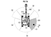
ε2<Vである場合、図15Aに示されているように第1指定対象範囲(右斜め後方対象範囲S6)にいる物体Qが作業機械200から離間している状態に相当する。V<-ε1である場合、図15Bに示されているように第1指定対象範囲(右斜め後方対象範囲S6)にいる物体Qが作業機械200に接近している状態に相当する。
物体の前回位置(前回制御周期における検知位置)または前回以前の所定期間にわたる位置の変位態様と、物体の今回位置と、の変位態様に基づき、作業機械200に対する当該物体の相対速度Vが求められる。作業機械200の並進および上部旋回体220の旋回などの作業機械200の動作状態に応じた、世界座標系における作業機械座標系の位置および姿勢のうち一方の相対的な変化態様が付加的に勘案されたうえで、作業機械200に対する当該物体の相対速度Vが求められてもよい。
作業機械200に対する当該物体の相対速度Vが-ε1≦V≦ε2であると判定された場合(図13/STEP210‥1)、第2制御要素122により、複数の出力装置130のうち第1指定出力装置を通じて態様「0」の警報が出力される(図13/STEP212)。「第1指定出力装置」は、複数の出力装置130のうち、作業機械200を基準とした第1指定対象空間の方位に対応して作業機械200の運転空間に配置されている出力装置である。例えば、第1指定対象空間が右斜め後方対象空間S6である場合、右斜め後方出力装置136が第1指定出力装置として警報を出力する(図4および図5参照)。第1指定対象空間が左斜め後方対象空間S4である場合、左斜め後方出力装置134が第1指定出力装置として警報を出力する。第1指定対象空間が後方対象空間S5である場合、後方出力装置135が第1指定出力装置として警報を出力する。
作業機械200に対する当該物体の相対速度Vがε2<Vであると判定された場合(図13/STEP210‥2)、第2制御要素122により、当該相対速度Vの大きさ|V|がV1(>ε2)未満であるか否かが判定される(図13/STEP214)。当該判定結果が肯定的である場合(図13/STEP214‥YES)、第2制御要素122により、第1指定出力装置を通じて態様「1-1」の警報が出力される(図13/STEP216)。当該判定結果が否定的である場合(図13/STEP214‥NO)、第2制御要素122により、第1指定出力装置を通じて態様「1-2」の警報が出力される(図13/STEP218)。
作業機械200に対する当該物体の相対速度VがV<-ε1であると判定された場合(図13/STEP210‥3)、第2制御要素122により、当該相対速度Vの大きさ|V|がV2(>ε1)未満であるか否かが判定される(図13/STEP220)。当該判定結果が肯定的である場合(図13/STEP220‥YES)、第2制御要素122により、第1指定出力装置を通じて態様「2-1」の警報が出力される(図13/STEP222)。当該判定結果が否定的である場合(図13/STEP220‥NO)、第2制御要素122により、第1指定出力装置を通じて態様「2-2」の警報が出力される(図13/STEP224)。
態様「0」、態様「1-1」、態様「1-2」、態様「2-1」および態様「2-2」は相互に異なっている。例えば、警報に音響が含まれる場合(出力装置130がピエゾ素子等からなる音声出力装置により構成されている場合)、図16Aに示されているように、態様0の音響周波数f=f0(t)が一定である。態様「1-1」、態様「1-2」、態様「2-1」および態様「2-2」は態様「0」の音響周波数f=f0(t)とは異なる周波数に設定される。図16A~図16Dにおいて時刻tは例えば警告周期に対応し、時刻t毎に警報をする。態様0以外の警報において、警報周期の中で音響周波数は強調の場合は徐々に増加、弱調の場合は徐々に低下させる様にしてもよい。
作業機械200に対する当該物体の相対速度Vが変化する場合には、態様「0」、態様「1-1」、態様「1-2」、態様「2-1」および態様「2-2」のいずれかに警報が変化する。
なお、上記実施形態では、態様「1-1」と「1-2」、態様「2-1」と「2-2」をそれぞれ2種類の警報レベルに対応させていたが3種類以上の警報レベルに対応させてもよい。2種類の警報で表現するよりも細かく遠近速度を警報できる。
警報音の周波数限らず音圧や間隔、警告灯では波長、輝度、周期等も同様に数種類の警報にしてもよい。
なお、上記実施形態では、態様「1-1」と「1-2」、態様「2-1」と「2-2」をそれぞれ2種類の警報レベルに対応させていたが3種類以上の警報レベルに対応させてもよい。2種類の警報で表現するよりも細かく遠近速度を警報できる。
警報音の周波数限らず音圧や間隔、警告灯では波長、輝度、周期等も同様に数種類の警報にしてもよい。
このように構成することで、態様「0」、態様「1-1」、態様「1-2」、態様「2-1」および態様「2-2」のみで警報されるため、警報を単純化することが出来る。オペレータは、単純化した警報により作業機械200と物体との間隔の変化態様を簡易に把握することが可能となる。
態様1-2の音響周波数f=f1-2(t)の低下速度は、態様1-1の音響周波数f=f1-1(t)の低下速度よりも高く調節されてもよい。態様1-2の音響周波数f=f1-2(t)の下限値は、態様1-1の音響周波数f=f1-1(t)の下限値よりも低く調節されてもよい。態様2-2の音響周波数f=f2-2(t)の上昇速度は、態様2-1の音響周波数f=f2-1(t)の上昇速度よりも高く調節されてもよい。態様2-2の音響周波数f=f1-2(t)の上限値は、態様2-1の音響周波数f=f1-1(t)の上限値よりも高く調節されてもよい。
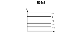
図16Bに示されているように、態様0の音圧レベルs=s0(t)が一定である。これに対して、態様1-1の音圧レベルs=s1-1(t)および態様1-2の音圧レベルs=s1-2(t)は時刻tとともにs=s0(t)から異なる下限値のそれぞれまで徐々に低下するように変化してもよい。態様2-1の音圧レベルs=s2-1(t)および態様2-2の音圧レベルs=s2-2(t)は時刻tとともにs=s0(t)から異なる上限値のそれぞれまで徐々に上昇するように変化してもよい。
態様1-2の音圧レベルs=s1-2(t)の低下速度は、態様1-1の音圧レベルs=s1-1(t)の低下速度よりも高く調節されてもよい。態様1-2の音圧レベルs=s1-2(t)の下限値は、態様1-1の音圧レベルs=s1-1(t)の下限値よりも低く調節されてもよい。態様2-2の音圧レベルs=s2-2(t)の上昇速度は、態様2-1の音圧レベルs=s2-1(t)の上昇速度よりも高く調節されてもよい。態様2-2の音圧レベルs=s1-2(t)の上限値は、態様2-1の音圧レベルs=s1-1(t)の上限値よりも高く調節されてもよい。
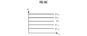
例えば、警報に可視光が含まれる場合(出力装置130が画像出力装置またはLED等の発光素子により構成されている場合)、図16Cに示されているように、態様0の可視光周波数ν=ν0(t)が一定である。これに対して、態様1-1の可視光周波数ν=ν1-1(t)および態様1-2の可視光周波数ν=ν1-2(t)は時刻tとともにν=ν0(t)から異なる下限値のそれぞれまで徐々に低下するように変化してもよい。態様2-1の可視光周波数ν=ν2-1(t)および態様2-2の可視光周波数ν=ν2-2(t)は時刻tとともにν=ν0(t)から異なる上限値のそれぞれまで徐々に上昇するように変化してもよい。
態様1-2の可視光周波数ν=ν1-2(t)の低下速度は、態様1-1の可視光周波数ν=ν1-1(t)の低下速度よりも高く調節されてもよい。態様1-2の可視光周波数ν=ν1-2(t)の下限値は、態様1-1の可視光周波数ν=ν1-1(t)の下限値よりも低く調節されてもよい。態様2-2の可視光周波数ν=ν2-2(t)の上昇速度は、態様2-1の可視光周波数ν=ν2-1(t)の上昇速度よりも高く調節されてもよい。態様2-2の可視光周波数ν=ν1-2(t)の上限値は、態様2-1の可視光周波数ν=ν1-1(t)の上限値よりも高く調節されてもよい。
図16Dに示されているように、態様0の輝度L=L0(t)が一定である。これに対して、態様1-1の輝度L=L1-1(t)および態様1-2の輝度L=L1-2(t)は時刻tとともにL=L0(t)から異なる下限値のそれぞれまで徐々に低下するように変化してもよい。態様2-1の輝度L=L2-1(t)および態様2-2の輝度L=L2-2(t)は時刻tとともにL=L0(t)から異なる上限値のそれぞれまで徐々に上昇するように変化してもよい。
態様1-2の輝度L=L1-2(t)の低下速度は、態様1-1の輝度L=L1-1(t)の低下速度よりも高く調節されてもよい。態様1-2の輝度L=L1-2(t)の下限値は、態様1-1の輝度L=L1-1(t)の下限値よりも低く調節されてもよい。態様2-2の輝度L=L2-2(t)の上昇速度は、態様2-1の輝度L=L2-1(t)の上昇速度よりも高く調節されてもよい。態様2-2の輝度L=L1-2(t)の上限値は、態様2-1の輝度L=L1-1(t)の上限値よりも高く調節されてもよい。
態様1-1、1-2、2-1および2-2にしたがって警報が出力された場合、第2制御要素122により、物体の位置が複数の対象空間のうち第1指定対象空間から他の対象空間である第2指定対象空間に向かっているか否か(当該物体の移動ベクトルの延長線が他の対象空間に重なっているか否か)が判定される(図14/STEP226)。
当該判定結果が否定的な場合(図14/STEP226‥NO)、今回周期における一連の処理が終了する。当該判定結果が肯定的な場合(図14/STEP226‥YES)、第2制御要素122により、当該他の対象空間が第2指定対象空間として定められる(図14/STEP228)。例えば、第1指定対象空間としての後方対象空間S5に存在する物体が、右斜め後方対象空間S6に向かって移動している場合、右斜め後方対象空間S6が第2指定対象空間として定められる。
続いて、第2制御要素122により、実空間位置における物体の速度Vaが基準速度Vat未満であるか否かが判定される(図14/STEP230)。実空間位置における物体の速度Vaが基準速度Vat未満であると判定された場合(図14/STEP230‥YES)、第2制御要素122により、態様p-1(p=1-1,1-2,2-1,2-2)にしたがって、第2指定出力装置を通じて警報(2次警報)が出力される(図14/STEP232)。実空間位置における物体の速度Vaが基準速度Vat以上であると判定された場合(図14/STEP230‥NO)、第2制御要素122により、態様p-2にしたがって、第2指定出力装置を通じて警報が出力される(図14/STEP234)。
第2指定出力装置は、作業機械200を基準とした第2指定対象空間の方位に対応して、運転空間に配置されている出力装置である。例えば、右斜め後方対象空間S6が第2指定対象空間として定められた場合、右斜め後方出力装置136が第2指定出力装置として2次警報を出力する。
態様p-1およびp-2の関係は、態様1-1および1-2の関係または態様2-1および2-2の関係と同様である(図16A~図16D参照)。
(作用効果)
作業機械200の操作装置400のオペレータによる操作状態に基づいて予測される作業機械200の動作態様に応じて、複数の対象空間の少なくとも一部が「第1指定対象空間」として定められる(図13/STEP202~206、図7A~図7C参照)。作業機械200の動作とは、作業機械200の全体的な動作のほか、その一部である動作部分の動作をも包含する概念である。物体の位置が第1指定対象空間に含まれている場合、第1指定出力装置により警報が出力され、当該警報が、作業機械200と物体との相対位置の変化態様に応じて差異化される(図13/STEP212,218,220,224,226、図16A~図16D参照)。第1指定出力装置は、作業機械200の運転空間においてオペレータの居場所(シート402の位置)を基準として、作業機械200を基準とする第1指定対象空間の方位に対応する方位に配置されている(図4参照)。「方位」とは、単一の方位角のみならず方位角範囲により特定され、さらには仰角範囲により特定されてもよい。
作業機械200の操作装置400のオペレータによる操作状態に基づいて予測される作業機械200の動作態様に応じて、複数の対象空間の少なくとも一部が「第1指定対象空間」として定められる(図13/STEP202~206、図7A~図7C参照)。作業機械200の動作とは、作業機械200の全体的な動作のほか、その一部である動作部分の動作をも包含する概念である。物体の位置が第1指定対象空間に含まれている場合、第1指定出力装置により警報が出力され、当該警報が、作業機械200と物体との相対位置の変化態様に応じて差異化される(図13/STEP212,218,220,224,226、図16A~図16D参照)。第1指定出力装置は、作業機械200の運転空間においてオペレータの居場所(シート402の位置)を基準として、作業機械200を基準とする第1指定対象空間の方位に対応する方位に配置されている(図4参照)。「方位」とは、単一の方位角のみならず方位角範囲により特定され、さらには仰角範囲により特定されてもよい。
これにより、作業機械200の運転空間においてシート402に着座しているオペレータが操作装置400を操作した際、第1指定出力装置により警報が出力された場合、当該操作状態に応じた作業機械200の動作方向に物体が存在することをオペレータに直感的に認識させることができる。
第2制御要素122が、作業機械200と物体Qとの相対位置に応じて定まる作業機械200と物体Qとの間隔の変化態様の相違に応じて異なる態様で第1指定出力装置に、警報を出力させる(図16A~図16D参照)。これにより、第1指定出力装置により出力される警報の相違に応じて、作業機械200と物体との間隔の変化態様、例えば、相対的に近づいているかまたは遠ざかっているかの相違をオペレータに直感的に認識させることができる(図15Aおよび図15B参照)。
第2制御要素122が、作業機械200と物体との間隔が小さくなっている場合、強調する警報を第1指定出力装置に出力させ、作業機械200と物体との間隔が大きくなっている場合、弱調する警報を第1指定出力装置に出力させる。具体的には、作業機械200と物体との間隔が狭まっている場合、周波数が比較的高い音を警報として第1指定出力装置に出力させる(図13/STEP222,224、図16A/f2-1(t)、f2-2(t)参照)。作業機械200と物体との間隔が広がっている場合、周波数が比較的低い音を警報として第1指定出力装置に出力させる(図13/STEP216,218、図16A/f1-1(t)、f1-2(t)参照)。これにより、第1指定出力装置により出力される警報の変化態様の相違に応じて、作業機械200と物体とが相対的に近づいているかまたは遠ざかっているかの相違をオペレータに直感的に認識させることができる。すなわち、第1指定出力装置により出力される警報としての音のドップラー効果のような周波数の変化態様の相違に応じて、作業機械200と物体とが相対的に近づいているかまたは遠ざかっているかの相違をオペレータに直感的に認識させることができる。
第2制御要素122が、前記作業機械と前記物体との間隔の変化速度が大きいほど、第1指定出力装置により出力される警報の強調または弱調の変化速度が大きくなるように調節する。具体的には、作業機械200と物体との間隔の変化速度が大きいほど、第1指定出力装置により出力される警報としての音の周波数の変化速度が大きくなる(図13/STEP214,216,218,STEP220,222,224、図16A/f1-1(t)、f1-2(t)、f2-1(t)、f2-2(t)参照)。これにより、第1指定出力装置により出力される警報の変化速度の高低に応じて、作業機械と物体との間隔の変化速度の高低をオペレータに直感的に認識させることができる。
物体の位置が複数の対象空間のうち第1指定対象空間から他の対象空間である第2指定対象空間に向かっている場合、第1指定出力装置に加えて第2指定出力装置に警報を出力させる(図14/STEP226,228,230,232,234参照)。例えば、第1指定対象空間としての後方対象空間S3に存在する物体が、作業機械200または上部旋回体220の第2指定対象空間としての右側対象空間S1に向かって移動している場合、後方出力装置133により1次警報が出力され、1次警報の出力開始後、1次警報の出力終了前または1次警報の出力終了後に、右側出力装置131により2次警報が出力される。この際、第2制御要素122が、物体の移動速度の高低に応じて、第1指定出力装置に警報を出力させる期間に対する、第2指定出力装置に警報を出力させる期間の比率を変化させてもよい。
これにより、第1指定出力装置および第2指定出力装置により出力される警報の相違に応じて、物体が第1指定対象空間から他の対象空間に向かって移動していることをオペレータに直感的に認識させることができる。複数の出力装置131~133のうち、先に警報が出力された一の出力装置(第1指定出力装置)の運転空間における配置方位に対応する一の対象空間(第1指定対象空間)から、後に警報が出力された他の出力装置(第2指定出力装置)の運転空間における配置方位に対応する他の対象空間(第2指定対象空間)に向かって物体が移動していることをオペレータに直感的に認識させることができる。
(本発明の他の実施形態)
第1検知要素111が、操作装置400のオペレータによる操作状態として、オペレータと操作装置400との非相互作用状態(例えば、オペレータが操作レバーに握っていないまたは触れていない状態)から相互作用状態(例えば、オペレータが操作レバーに握っているまたは触れている状態)への遷移、または、オペレータにより操作装置400が不感帯において操作されている状態を検知してもよい。操作レバーの0ではない操作量が検知されたものの、その大きさが閾値未満である場合、オペレータと操作装置400との非相互作用状態から相互作用状態への遷移、または、オペレータにより操作装置400が不感帯において操作されている状態が検知されてもよい。さらに、第1検知要素111による当該状態が検知されたことを要件として、第2出力装置122により出力装置130が警報出力が可能な状態に制御されてもよい。
第1検知要素111が、操作装置400のオペレータによる操作状態として、オペレータと操作装置400との非相互作用状態(例えば、オペレータが操作レバーに握っていないまたは触れていない状態)から相互作用状態(例えば、オペレータが操作レバーに握っているまたは触れている状態)への遷移、または、オペレータにより操作装置400が不感帯において操作されている状態を検知してもよい。操作レバーの0ではない操作量が検知されたものの、その大きさが閾値未満である場合、オペレータと操作装置400との非相互作用状態から相互作用状態への遷移、または、オペレータにより操作装置400が不感帯において操作されている状態が検知されてもよい。さらに、第1検知要素111による当該状態が検知されたことを要件として、第2出力装置122により出力装置130が警報出力が可能な状態に制御されてもよい。
当該構成の作業機械用周辺監視装置100によれば、オペレータが作業機械200を動作させる意思がある蓋然性が高い一方で作業機械200がまだ動作を開始していない操作初期段階で、オペレータによる操作装置400の操作に応じた作業機械200の動作方向に物体が存在することを、当該オペレータに直感的に認識させ、かつ、当該警報の相違に応じて、作業機械200と物体との相対位置の変化態様の相違をオペレータに直感的に認識させることができる。
図10Aに示されているように、下部走行体210に対する上部旋回体220の旋回軸線を基準点とする同心円環状の複数の環状領域R11~R14が定義されていてもよい。図10Bに示されているように、下部走行体210に対する上部旋回体220の旋回軸線を基準点とする同心矩形環状の複数の環状領域R21~R23が定義されていてもよい。作業機械200の運転空間である遠隔操作室(またはキャブ222の内部空間)においてオペレータが着座するシート402(オペレータの居場所)の座部を基準点として複数の環状領域が定義されていてもよい。
基準の警報を確かめる機能を搭載してもよい。例えば物体の速度Vが0の時の警報音周波数や、物体が先端バケットの基準位置にあるときの距離を示す警報を確かめるモードを搭載することで、オペレータが警報の基準を確認することができる。
第2制御要素122が、第1指定出力装置に警報を出力させた後で、第2指定出力装置に警報を出力させてもよい。
当該構成の作業機械用周辺監視装置100によれば、複数の出力装置130のうち、先に警報が出力された一の出力装置(第1指定出力装置)の運転空間における配置方位に対応する一の対象空間(第1指定対象空間)から、後に警報が出力された他の出力装置(第2指定出力装置)の運転空間における配置方位に対応する他の対象空間(第2指定対象空間)に向かって物体が移動していることをオペレータに直感的に認識させることができる。
第2制御要素122が、物体の移動速度の高低に応じて、第1指定出力装置に警報を出力させる期間に対する、第2指定出力装置に警報を出力させる期間の比率を変化させてもよい。
当該構成の作業機械用周辺監視装置によれば、前記のように一の対象空間(第1指定対象空間)から他の対象空間(第2指定対象空間)に向かって物体が移動していることをオペレータに直感的に認識させることができる。さらに、第1指定出力装置による警報出力期間と、第2指定出力装置による警報出力期間との比に応じて、物体の当該移動速度の高低をオペレータに直感的に認識させることができる。
第2制御要素122が、作業機械200と物体との相対位置、および、作業機械200と物体との間隔の変化態様のそれぞれの相違に応じて、警報としての警報音を構成する複数の要素のそれぞれが異なる態様で差異化された当該警報を第1指定出力装置に出力させることが好ましい。
当該構成の作業機械用周辺監視装置によれば、物体の作業機械200との相対位置とその変化態様を一つの警報手段で同時に表現でき、オペレータに直感的に認識させることができる。
100‥作業機械用周辺監視装置、111‥第1検知要素、112‥第2検知要素、121‥第1制御要素、122‥第2制御要素、130‥出力装置、131‥右斜め前方出力装置、132‥前方出力装置、133‥左斜め前方出力装置、134‥左斜め後方出力装置、135‥後方出力装置、136‥右斜め後方出力装置、200‥作業機械、400‥操作装置、402‥シート(オペレータの居場所)、A1‥右側検知対象空間、A2‥前方検知対象空間、A3‥左側検知対象空間、A4‥後方検知対象空間、C1‥右側センサ、C2‥前方センサ、C3‥左側センサ、C4‥後方センサ、S1‥右斜め前方対象空間、S2‥前方対象空間、S3‥左斜め前方対象空間、S4‥左斜め後方対象空間、S5‥後方対象空間、S6‥右斜め後方対象空間。
Claims (9)
- オペレータによる作業機械を動作させるための操作装置の操作状態を検知する第1検知要素と、
前記作業機械の周囲に存在する物体の位置を検知する第2検知要素と、
前記作業機械を基準として複数の対象空間のそれぞれの方位に対応するように、前記作業機械の運転空間においてオペレータの居場所を基準として複数の方位のそれぞれに配置された、当該オペレータに対して警報を出力する複数の出力装置と、
前記第1検知要素により検知された前記操作状態から予測される前記作業機械の動作態様に応じて、前記複数の対象空間のうち少なくとも一部である第1指定対象空間を定める第1制御要素と、
前記第1制御要素により定められた前記第1指定対象空間に、前記第2検知要素により検知された前記物体の位置が含まれている場合、前記複数の出力装置のうち、前記作業機械を基準とした前記第1指定対象空間の方位に対応して前記作業機械の運転空間に配置されている第1指定出力装置に、前記第2検知要素により検知された前記物体の位置の時系列により定まる前記作業機械に対する前記物体の相対位置の変化態様に応じて異なる警報を出力させる第2制御要素と、を備えていることを特徴とする作業機械用周辺監視装置。 - 請求項1記載の作業機械用周辺監視装置において、
前記第2制御要素が、前記作業機械と前記物体との相対位置に応じて定まる前記作業機械と前記物体との間隔の変化態様の相違に応じて異なる態様で前記第1指定出力装置に、警報を出力させることを特徴とする作業機械用周辺監視装置。 - 請求項2記載の作業機械用周辺監視装置において、
前記第2制御要素が、前記作業機械と前記物体との間隔が小さくなっている場合、強調する警報を前記第1指定出力装置に出力させ、前記作業機械と前記物体との間隔が大きくなっている場合、弱調する警報を前記第1指定出力装置に出力させることを特徴とする作業機械用周辺監視装置。 - 請求項3記載の作業機械用周辺監視装置において、
前記第2制御要素が、前記作業機械と前記物体との間隔の変化速度が大きいほど、前記第1指定出力装置により出力される警報の強調または弱調の変化速度が大きくなるように調節することを特徴とする作業機械用周辺監視装置。 - 請求項1~4のうちいずれか1項に記載の作業機械用周辺監視装置において、
前記第2制御要素が、前記第2検知要素によって検知された前記物体の位置が前記複数の対象空間のうち前記第1指定対象空間から他の対象空間である第2指定対象空間に向かっている場合、前記第1指定出力装置に加えて、前記作業機械を基準とした前記第2指定対象空間の方位に対応して、前記運転空間に配置されている第2指定出力装置に警報を出力させることを特徴とする作業機械用周辺監視装置。 - 請求項5記載の作業機械用周辺監視装置において、
前記第2制御要素が、前記第1指定出力装置に警報を出力させた後で、前記第2指定出力装置に警報を出力させることを特徴とする作業機械用周辺監視装置。 - 請求項6記載の作業機械用周辺監視装置において、
前記第2制御要素が、前記物体の移動速度の高低に応じて、前記第1指定出力装置に警報を出力させる期間に対する、前記第2指定出力装置に警報を出力させる期間の比率を変化させることを特徴とする作業機械用周辺監視装置。 - 請求項1~7のうちいずれか1項に記載の作業機械用周辺監視装置において、
前記第1検知要素が、前記操作装置の前記オペレータによる操作状態として、前記オペレータと前記操作装置との非相互作用状態から相互作用状態への遷移、または、前記オペレータにより前記操作装置が不感帯において操作されている状態を検知することを要件として、前記第2制御要素が、前記出力装置を警報出力可能な状態に制御することを特徴とする作業機械用周辺監視装置。 - 請求項1~8のうちいずれか1項に記載の作業機械用周辺監視装置において、
前記第2制御要素が、前記作業機械と前記物体との相対位置、および、前記作業機械と前記物体との間隔の変化態様のそれぞれの相違に応じて、前記警報としての警報音を構成する複数の要素のそれぞれが異なる態様で差異化された当該警報を前記第1指定出力装置に出力させることを特徴とする作業機械用周辺監視装置。
Priority Applications (3)
| Application Number | Priority Date | Filing Date | Title |
|---|---|---|---|
| US17/435,570 US20220064909A1 (en) | 2019-03-13 | 2019-12-02 | Periphery monitoring apparatus for work machine |
| EP19918757.6A EP3913150A4 (en) | 2019-03-13 | 2019-12-02 | Periphery monitoring apparatus for work machine |
| CN201980093769.3A CN113614320B (zh) | 2019-03-13 | 2019-12-02 | 作业机械用周边监视装置 |
Applications Claiming Priority (2)
| Application Number | Priority Date | Filing Date | Title |
|---|---|---|---|
| JP2019-045388 | 2019-03-13 | ||
| JP2019045388A JP2020149261A (ja) | 2019-03-13 | 2019-03-13 | 作業機械用周辺監視装置 |
Publications (1)
| Publication Number | Publication Date |
|---|---|
| WO2020183814A1 true WO2020183814A1 (ja) | 2020-09-17 |
Family
ID=72427815
Family Applications (1)
| Application Number | Title | Priority Date | Filing Date |
|---|---|---|---|
| PCT/JP2019/047026 Ceased WO2020183814A1 (ja) | 2019-03-13 | 2019-12-02 | 作業機械用周辺監視装置 |
Country Status (5)
| Country | Link |
|---|---|
| US (1) | US20220064909A1 (ja) |
| EP (1) | EP3913150A4 (ja) |
| JP (1) | JP2020149261A (ja) |
| CN (1) | CN113614320B (ja) |
| WO (1) | WO2020183814A1 (ja) |
Families Citing this family (9)
| Publication number | Priority date | Publication date | Assignee | Title |
|---|---|---|---|---|
| US11521397B2 (en) * | 2020-09-08 | 2022-12-06 | Caterpillar Inc. | Object tracking for work machines |
| CN113655793B (zh) * | 2021-08-12 | 2024-08-09 | 上海三一重机股份有限公司 | 一种避障控制方法、装置及工程机械 |
| JP7739111B2 (ja) | 2021-09-29 | 2025-09-16 | 株式会社小松製作所 | 障害物検知警報システム、障害物検知警報方法、および作業機械 |
| JP7822150B2 (ja) * | 2021-09-30 | 2026-03-02 | パナソニックアドバンストテクノロジー株式会社 | 衝突防止装置、衝突防止方法、及び、プログラム |
| JP2023121484A (ja) * | 2022-02-21 | 2023-08-31 | 文化シヤッター株式会社 | 建具装置 |
| CN115339528B (zh) * | 2022-08-03 | 2024-04-26 | 北京主线科技有限公司 | 一种卡车驾驶室翻转控制方法、装置及存储介质 |
| JP7792879B2 (ja) * | 2022-09-22 | 2025-12-26 | 本田技研工業株式会社 | 情報管理装置、情報管理方法、およびプログラム |
| CN116189380B (zh) * | 2022-12-26 | 2024-08-02 | 湖北工业大学 | 机械设备人机安全交互方法、系统、装置以及介质 |
| US20250382775A1 (en) * | 2024-06-18 | 2025-12-18 | Chimei Motor Electronics Co., Ltd. | Cockpit warning and identification system |
Citations (3)
| Publication number | Priority date | Publication date | Assignee | Title |
|---|---|---|---|---|
| JP2017078315A (ja) * | 2015-10-22 | 2017-04-27 | 株式会社神戸製鋼所 | 建設機械の干渉防止装置 |
| JP2017523523A (ja) * | 2014-07-28 | 2017-08-17 | エス・エム・エス・スマート・マイクロウェーブ・センサーズ・ゲーエムベーハー | 車両に配置される装置 |
| JP2018093501A (ja) | 2018-01-04 | 2018-06-14 | 住友重機械工業株式会社 | 作業機械 |
Family Cites Families (7)
| Publication number | Priority date | Publication date | Assignee | Title |
|---|---|---|---|---|
| JPH1072851A (ja) * | 1996-08-30 | 1998-03-17 | Shin Caterpillar Mitsubishi Ltd | 侵入移動体検出装置 |
| JP5227841B2 (ja) * | 2009-02-27 | 2013-07-03 | 日立建機株式会社 | 周囲監視装置 |
| EP2808455B1 (en) * | 2012-01-27 | 2018-05-30 | Doosan Infracore Co., Ltd. | Operational stability enhancing device for construction machinery |
| JP6545430B2 (ja) * | 2013-03-19 | 2019-07-17 | 住友重機械工業株式会社 | ショベル |
| JP6267972B2 (ja) * | 2014-01-23 | 2018-01-24 | 日立建機株式会社 | 作業機械の周囲監視装置 |
| EP3386195A4 (en) * | 2015-11-30 | 2018-12-19 | Sumitomo Heavy Industries, LTD. | Periphery monitoring system for work machine |
| JP6468444B2 (ja) * | 2016-04-28 | 2019-02-13 | コベルコ建機株式会社 | 建設機械 |
-
2019
- 2019-03-13 JP JP2019045388A patent/JP2020149261A/ja active Pending
- 2019-12-02 EP EP19918757.6A patent/EP3913150A4/en not_active Withdrawn
- 2019-12-02 CN CN201980093769.3A patent/CN113614320B/zh not_active Expired - Fee Related
- 2019-12-02 WO PCT/JP2019/047026 patent/WO2020183814A1/ja not_active Ceased
- 2019-12-02 US US17/435,570 patent/US20220064909A1/en not_active Abandoned
Patent Citations (3)
| Publication number | Priority date | Publication date | Assignee | Title |
|---|---|---|---|---|
| JP2017523523A (ja) * | 2014-07-28 | 2017-08-17 | エス・エム・エス・スマート・マイクロウェーブ・センサーズ・ゲーエムベーハー | 車両に配置される装置 |
| JP2017078315A (ja) * | 2015-10-22 | 2017-04-27 | 株式会社神戸製鋼所 | 建設機械の干渉防止装置 |
| JP2018093501A (ja) | 2018-01-04 | 2018-06-14 | 住友重機械工業株式会社 | 作業機械 |
Non-Patent Citations (1)
| Title |
|---|
| See also references of EP3913150A4 |
Also Published As
| Publication number | Publication date |
|---|---|
| CN113614320A (zh) | 2021-11-05 |
| JP2020149261A (ja) | 2020-09-17 |
| CN113614320B (zh) | 2023-03-31 |
| EP3913150A4 (en) | 2022-03-30 |
| US20220064909A1 (en) | 2022-03-03 |
| EP3913150A1 (en) | 2021-11-24 |
Similar Documents
| Publication | Publication Date | Title |
|---|---|---|
| JP2020149261A (ja) | 作業機械用周辺監視装置 | |
| CN113039094B (zh) | 工程机械用周边监视装置 | |
| JP6158906B2 (ja) | 作業車両の周辺監視装置 | |
| US11781290B2 (en) | Shovel and output device of shovel | |
| WO2019244574A1 (ja) | 掘削機、情報処理装置 | |
| AU2022200817B2 (en) | Industrial vehicle | |
| JP7147248B2 (ja) | クレーン車 | |
| JP2016024778A (ja) | 車両用報知システム、報知制御装置、及び報知装置 | |
| JP7438807B2 (ja) | ショベルの施工支援システム | |
| WO2019186816A1 (ja) | 鞍乗り型車両 | |
| US11186964B2 (en) | Shovel | |
| WO2020170527A1 (ja) | 作業機械用周辺監視装置 | |
| JP2018042148A (ja) | 車両用画像処理装置 | |
| JP6980391B2 (ja) | 作業機械用周辺監視システム | |
| JP2021028266A (ja) | 作業機械及び作業機械の制御方法 | |
| JP2018111981A (ja) | 作業機械用周辺監視システム | |
| US20250283305A1 (en) | Work machine and operation system for work machine | |
| JP2021134533A (ja) | 安全装置および作業機械 | |
| JP7206956B2 (ja) | 作業機械 | |
| KR20210079525A (ko) | 근거리 후방 감지 헬멧 장치 | |
| JP7843878B2 (ja) | 運転支援装置、運転支援方法、およびプログラム | |
| US20250283306A1 (en) | Work machine and control system for work machine | |
| JP2006195877A (ja) | 作業機械 | |
| JP5828492B1 (ja) | 荷役車両 | |
| JP2022042244A (ja) | 作業車両及び報知方法 |
Legal Events
| Date | Code | Title | Description |
|---|---|---|---|
| 121 | Ep: the epo has been informed by wipo that ep was designated in this application |
Ref document number: 19918757 Country of ref document: EP Kind code of ref document: A1 |
|
| ENP | Entry into the national phase |
Ref document number: 2019918757 Country of ref document: EP Effective date: 20210816 |
|
| NENP | Non-entry into the national phase |
Ref country code: DE |