WO2020183856A1 - 眼内レンズ挿入器具 - Google Patents
眼内レンズ挿入器具 Download PDFInfo
- Publication number
- WO2020183856A1 WO2020183856A1 PCT/JP2019/050238 JP2019050238W WO2020183856A1 WO 2020183856 A1 WO2020183856 A1 WO 2020183856A1 JP 2019050238 W JP2019050238 W JP 2019050238W WO 2020183856 A1 WO2020183856 A1 WO 2020183856A1
- Authority
- WO
- WIPO (PCT)
- Prior art keywords
- intraocular lens
- insertion device
- support portion
- protrusion
- hollow body
- Prior art date
- Legal status (The legal status is an assumption and is not a legal conclusion. Google has not performed a legal analysis and makes no representation as to the accuracy of the status listed.)
- Ceased
Links
Images




Classifications
-
- A—HUMAN NECESSITIES
- A61—MEDICAL OR VETERINARY SCIENCE; HYGIENE
- A61F—FILTERS IMPLANTABLE INTO BLOOD VESSELS; PROSTHESES; DEVICES PROVIDING PATENCY TO, OR PREVENTING COLLAPSING OF, TUBULAR STRUCTURES OF THE BODY, e.g. STENTS; ORTHOPAEDIC, NURSING OR CONTRACEPTIVE DEVICES; FOMENTATION; TREATMENT OR PROTECTION OF EYES OR EARS; BANDAGES, DRESSINGS OR ABSORBENT PADS; FIRST-AID KITS
- A61F2/00—Filters implantable into blood vessels; Prostheses, i.e. artificial substitutes or replacements for parts of the body; Appliances for connecting them with the body; Devices providing patency to, or preventing collapsing of, tubular structures of the body, e.g. stents
- A61F2/02—Prostheses implantable into the body
- A61F2/14—Eye parts, e.g. lenses or corneal implants; Artificial eyes
- A61F2/16—Intraocular lenses
- A61F2/1662—Instruments for inserting intraocular lenses into the eye
- A61F2/167—Instruments for inserting intraocular lenses into the eye with pushable plungers
-
- A—HUMAN NECESSITIES
- A61—MEDICAL OR VETERINARY SCIENCE; HYGIENE
- A61F—FILTERS IMPLANTABLE INTO BLOOD VESSELS; PROSTHESES; DEVICES PROVIDING PATENCY TO, OR PREVENTING COLLAPSING OF, TUBULAR STRUCTURES OF THE BODY, e.g. STENTS; ORTHOPAEDIC, NURSING OR CONTRACEPTIVE DEVICES; FOMENTATION; TREATMENT OR PROTECTION OF EYES OR EARS; BANDAGES, DRESSINGS OR ABSORBENT PADS; FIRST-AID KITS
- A61F2/00—Filters implantable into blood vessels; Prostheses, i.e. artificial substitutes or replacements for parts of the body; Appliances for connecting them with the body; Devices providing patency to, or preventing collapsing of, tubular structures of the body, e.g. stents
- A61F2/02—Prostheses implantable into the body
- A61F2/14—Eye parts, e.g. lenses or corneal implants; Artificial eyes
- A61F2/16—Intraocular lenses
- A61F2/1662—Instruments for inserting intraocular lenses into the eye
- A61F2/1678—Instruments for inserting intraocular lenses into the eye with a separate cartridge or other lens setting part for storage of a lens, e.g. preloadable for shipping
-
- A—HUMAN NECESSITIES
- A61—MEDICAL OR VETERINARY SCIENCE; HYGIENE
- A61F—FILTERS IMPLANTABLE INTO BLOOD VESSELS; PROSTHESES; DEVICES PROVIDING PATENCY TO, OR PREVENTING COLLAPSING OF, TUBULAR STRUCTURES OF THE BODY, e.g. STENTS; ORTHOPAEDIC, NURSING OR CONTRACEPTIVE DEVICES; FOMENTATION; TREATMENT OR PROTECTION OF EYES OR EARS; BANDAGES, DRESSINGS OR ABSORBENT PADS; FIRST-AID KITS
- A61F9/00—Methods or devices for treatment of the eyes; Devices for putting in contact-lenses; Devices to correct squinting; Apparatus to guide the blind; Protective devices for the eyes, carried on the body or in the hand
- A61F9/007—Methods or devices for eye surgery
- A61F9/00736—Instruments for removal of intra-ocular material or intra-ocular injection, e.g. cataract instruments
-
- A—HUMAN NECESSITIES
- A61—MEDICAL OR VETERINARY SCIENCE; HYGIENE
- A61F—FILTERS IMPLANTABLE INTO BLOOD VESSELS; PROSTHESES; DEVICES PROVIDING PATENCY TO, OR PREVENTING COLLAPSING OF, TUBULAR STRUCTURES OF THE BODY, e.g. STENTS; ORTHOPAEDIC, NURSING OR CONTRACEPTIVE DEVICES; FOMENTATION; TREATMENT OR PROTECTION OF EYES OR EARS; BANDAGES, DRESSINGS OR ABSORBENT PADS; FIRST-AID KITS
- A61F2/00—Filters implantable into blood vessels; Prostheses, i.e. artificial substitutes or replacements for parts of the body; Appliances for connecting them with the body; Devices providing patency to, or preventing collapsing of, tubular structures of the body, e.g. stents
- A61F2/02—Prostheses implantable into the body
- A61F2/14—Eye parts, e.g. lenses or corneal implants; Artificial eyes
- A61F2/16—Intraocular lenses
- A61F2002/1681—Intraocular lenses having supporting structure for lens, e.g. haptics
Definitions
- the present invention relates to an intraocular lens insertion device.
- a soft intraocular lens made of a soft material such as silicone elastomer is inserted into the eye using an intraocular lens insertion device.
- the intraocular lens When a soft intraocular lens is inserted into the eye, the intraocular lens can be folded and the incision in the cornea can be reduced.
- Patent Document 1 As a method of folding an intraocular lens, a method of folding it in an intraocular lens insertion device is known (for example, Patent Document 1 by the applicant).
- a protrusion is provided on the case, and by fitting the intraocular lens insertion device and the case, the protrusion of the case is formed through the protrusion insertion hole provided in the intraocular lens insertion device. (Paragraph 0038, FIGS. 3 to 6, etc.).
- the intraocular lens having a substantially disk-shaped optical portion having an optical function and a pair of support portions extending from the optical portion is advanced toward the discharge hole of the nozzle portion.
- the tip of the anterior support portion of the intraocular lens abuts on the protrusion and can be folded back (paragraph 0041, FIG. 6, FIG. 7, etc.).
- the front support portion of the intraocular lens is folded back and the optical portion of the intraocular lens is also folded by advancing the intraocular lens.
- the front support portion is wrapped by an inner surface (hereinafter referred to as an inner surface) during this folding.
- an inner surface Such an ideal folded state is also called tacking.
- the present inventor has investigated that when the intraocular lens is advanced, the front support portion may enter between the outer surface opposite to the inner surface of the optical portion and the inner wall of the intraocular lens insertion device. Clarified by.
- the operator will distort the anterior support after releasing the intraocular lens, that is, in the patient's eye. I have to put it back. In that case, it imposes a heavy burden on the surgeon.
- the technical subject of the present invention is to provide an intraocular lens insertion device that improves the accuracy of tacking.
- the present inventor has diligently studied the above issues. At that time, the present inventor paid attention to the movement when the front support portion abuts on the protruding portion described in Patent Document 1.
- the protruding portion described in Patent Document 1 when the entire intraocular lens advances forward, the front support portion continues to bend backward and the tip of the front support portion is the inner wall of the intraocular lens insertion device. It was clarified that the timing of moving to the vicinity and the timing of advancing the peripheral edge of the optical part in the folded intraocular lens are very close, or the tip of the front support part tends to move to the inner wall earlier. ..
- the present inventor suppresses the bending of the front support portion by temporarily holding the tip of the front support portion that bends backward when the entire intraocular lens advances. He created the technical idea of delaying the timing of moving near the inner wall of the intraocular lens insertion device.
- the first aspect of the present invention is An intraocular lens insertion device for inserting an intraocular lens having an optical portion having an optical function and a support portion extending from the optical portion into the eye.
- the front support portion is one of the support portions and has a protrusion portion that abuts the front support portion and bends the front support portion.
- the protrusion is an intraocular lens insertion device having a holding portion that temporarily suppresses the progress of bending of the front support portion by holding the front support portion when the intraocular lens is folded.
- the second aspect of the present invention is the invention described in the first aspect.
- the hollow body which is the main body of the insertion device, A lens installation portion provided inside the hollow body and A forward member for advancing the intraocular lens arranged in the lens installation portion,
- the protrusions arranged in front of the lens installation portion and protruding from the inner wall of the hollow body, and the protrusions.
- It has an insertion cylinder arranged at the front tip portion of the hollow body, and has.
- the insertion cylinder has a hollow insertion cylinder main body and a tubular nozzle portion.
- the protrusions are in front of the first contact portion that bends the front support portion by contacting the front support portion when the intraocular lens is advanced by the advance member, and the front of the first contact portion.
- the holding portion is arranged in front of the support portion receiving portion that supports the front support portion after the front support portion is separated from the first contact portion, and the support portion receiving portion. It has a second contact portion that comes into contact with the front support portion while being supported.
- a third aspect of the present invention is the invention described in the second aspect.
- the first contact portion and the holding portion are chamfered.
- a fourth aspect of the present invention is An intraocular lens insertion device for inserting an intraocular lens having an optical portion and a support portion extending from the optical portion into the eye.
- a hollow body having a lens mounting portion on which the intraocular lens is placed with the optical axis direction of the intraocular lens as the vertical direction. It has a protrusion that protrudes from the inner wall of the hollow body and has at least one step that is upward when viewed forward from the lens mounting portion and a wall that is arranged in front of the step. It is an intraocular lens insertion device.
- a fifth aspect of the present invention is the invention described in the fourth aspect.
- the protrusion protrudes from the lower side to the upper side of the inner wall of the hollow body, and has at least two steps upward when viewed from the lens mounting portion toward the front.
- a sixth aspect of the present invention is the invention described in any one of the first to fifth aspects.
- the slope is arranged on the rearmost side of the protrusion.
- a seventh aspect of the present invention is the invention described in any one of the first to sixth aspects. Further having a case to be fitted with the hollow body, The protrusion is provided on the case and The hollow body is formed with a hole into which the protrusion can be fitted.
- the eighth aspect of the present invention is the invention described in any one of the first to seventh aspects. Further having the intraocular lens
- the optical portion of the intraocular lens and the proximal end side of the support portion are made of a soft material.
- the optical portion of the intraocular lens has an effective optical portion that performs an optical function, and a flat peripheral portion that is arranged around the effective optical portion.
- an intraocular lens insertion device that improves the accuracy of tacking.
- FIG. 1 is a perspective view showing a configuration example of the appearance of the intraocular lens insertion device according to the embodiment of the present invention.
- FIG. 2 is a perspective view showing the structure and arrangement of the tip portion of the insertion instrument main body according to the embodiment of the present invention.
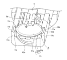
- FIG. 3 is a perspective view of the case of the intraocular lens insertion device according to the embodiment of the present invention.
- FIG. 4 is a perspective view showing a state in which the intraocular lens insertion device according to the embodiment of the present invention is attached to the case.
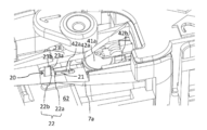
- FIG. 5 is a perspective view showing a state in the vicinity of a protrusion in the intraocular lens insertion device according to the embodiment of the present invention.
- FIG. 1 is a perspective view showing a configuration example of the appearance of the intraocular lens insertion device according to the embodiment of the present invention.
- FIG. 2 is a perspective view showing the structure and arrangement of the tip portion of the insertion instrument main body according to the embodiment of the present invention.
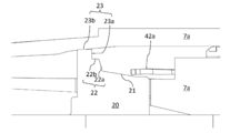
- FIG. 6 is a side view showing the vicinity of the protrusion in the intraocular lens insertion device according to the embodiment of the present invention when viewed from Y1 to Y2.
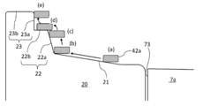
- FIG. 7 is a schematic cross-sectional view showing the movement of the front support portion (cross-sectional view) with respect to the protrusion portion in the intraocular lens insertion device according to the embodiment of the present invention.
- FIG. 8 is a schematic side view showing the vicinity of the protrusion in the intraocular lens insertion device according to the modified example (No. 1) of the present invention when viewed from Y1 to Y2.
- FIG. 9 is a schematic side view showing the vicinity of the protrusion in the intraocular lens insertion device according to the modified example (No.
- FIG. 10 is a schematic side view showing the vicinity of the protrusion in the intraocular lens insertion device according to the modified example (No. 3) of the present invention when viewed from Y1 to Y2.
- ⁇ refers to a predetermined value or more and a predetermined value or less.
- one of the X-axis directions is the X1 direction
- the other is the X2 direction
- one of the Y-axis directions is The Y1 direction
- the other is the Y2 direction
- one in the Z-axis direction is the Z1 direction
- the other is the Z2 direction.
- the X1 direction is the tip side (front, lens traveling direction)
- the X2 direction is the rear end side (rear)
- the Y1 direction is the left side (left)
- the Y2 direction is the right side (right side)
- the Z1 direction is the upper side (upper).
- the thickness direction and the optical axis direction when the intraocular lens is placed) and the Z2 direction are defined as the lower side (lower side).
- the X1 direction and the X2 direction correspond to the length direction of the intraocular lens insertion device 1
- the Y1 direction and the Y2 direction correspond to the width direction of the intraocular lens insertion device
- the Z1 direction and the Z2 direction correspond to the width direction of the intraocular lens insertion device. It corresponds to the height direction of the intraocular lens insertion device 1.
- the main feature portions in the present embodiment are the protrusion 21 (FIGS. 3 to 6, etc. in the first embodiment of Patent Document 1) and the protrusion 52 described in Patent Document 1. (FIG. 7, etc. in the second embodiment of Patent Document 1), the protrusion 80 (FIG. 8, FIG. 10, FIG. 11, etc. in the third embodiment of Patent Document 1). Therefore, the description will be simplified except for the portion related to the protrusion for bending the front support portion in the intraocular lens insertion device.
- the configuration of a known intraocular lens insertion device may be adopted except for the part related to the protrusion for bending the front support part.
- the structure of WO2018 / 003854 by the applicant may be adopted.
- the contents not described below shall adopt the configuration of a known intraocular lens insertion device (for example, the configuration of WO2018 / 003854), and all the descriptions of WO2018 / 003854 are described in the present specification. It shall be.
- FIG. 1 is a perspective view showing a configuration example of the appearance of the intraocular lens insertion device according to the embodiment of the present invention.
- FIG. 2 is a perspective view showing the structure and arrangement of the tip portion of the insertion instrument main body according to the embodiment of the present invention.
- the configurations of FIGS. 1 and 2 of the present application are similar to those of FIGS. 1 and 6 of WO2018 / 003854 except for the intraocular lens 4. Therefore, among the codes shown in FIG. 2 of the present application, the reference numerals not described in the present specification are as described in WO2018 / 003854.
- the intraocular lens insertion device 1 is used when inserting an intraocular lens into the eye.
- a one-piece type intraocular lens 4 (see FIG. 2) made of a soft material such as silicone elastomer or soft acrylic, which has circular effective optics that fulfills an optical function.
- An intraocular lens 4 having an optical portion 41 including a portion 41a and a peripheral portion 41b thereof and two support portions 42a and 42b curved from two locations on the outer peripheral portion of the optical portion 41 and extending outward is handled.
- Reference numeral 42a indicates a front support portion arranged in the front when the lens is installed in the lens installation portion 11
- reference numeral 42b indicates a rear support portion arranged in the rear.
- optical portion 41 of the intraocular lens 4 and the proximal end side of the support portions 42a and 42b connected to the optical portion 41 are made of a soft material. This configuration facilitates folding of the intraocular lens 4.
- the terminal sides of the support portions 42a and 42b may also be made of a soft material or a hard material (eg, polyethylene, PMMA, etc.).
- the effective optical portion 41a in the optical portion 41 has a shape that exerts an optical function
- the peripheral portion 41b is formed in an annular shape around the effective optical portion 41a, and the annular portion has a flat plate shape.
- the optical unit 41 may be configured from only the effective optical unit 41a.
- the peripheral edge portion 41b may be formed continuously with the effective optical portion 41a, that is, the peripheral edge portion 41b and the effective optical portion 41a may be smoothly connected to form a continuous surface.
- the intraocular lens insertion device 1 includes an insertion device main body 5, a slider 6, an insertion tube 7, a rotating member 8, a plunger 9, and a rod (arranged and hidden inside the intraocular lens insertion device 1 of FIG. 1). (Not shown), and the configuration is provided with. Each of these components is preferably composed of a resin molded product.
- the insertion instrument main body 5 and the insertion cylinder 7 each have a hollow structure, and are connected to each other to form a hollow body.
- the slider 6 is attached to the insertion instrument main body 5.
- the insertion cylinder 7 is arranged so as to communicate with the tip of the insertion instrument main body 5.
- the insertion cylinder 7 and the tip of the insertion instrument main body 5 may be integrally molded, or may be molded separately and the insertion cylinder 7 may be attached to the tip.
- the insertion cylinder 7 has a hollow insertion cylinder main body 7a and a thin tubular nozzle portion 7b.
- the lens installation portion 11 of the insertion instrument main body 5 is housed and arranged in the insertion cylinder main body 7a of the insertion cylinder 7 together with the intraocular lens 4 installed there.
- An injection hole 7c is formed on the upper surface of the insertion cylinder body 7a.
- the injection hole 7c is for injecting a viscoelastic substance (for example, sodium hyaluronate).
- the viscoelastic substance injected from the injection hole 7c is supplied to the intraocular lens 4 installed in the lens installation portion 11.
- the rotating member 8 is rotatably connected to the rear end of the insertion instrument main body 5.
- the plunger 9 is arranged coaxially with the insertion instrument main body 5. A part of the plunger 9 is arranged inside the insertion instrument main body 5 via the rotating member 8, and the other part of the plunger 9 is arranged so as to project rearward from the rotating member 8.
- the rod is arranged inside a hollow body composed of the insertion instrument main body 5 and the insertion cylinder 7.
- the rod is connected to the plunger 9 and plays a role of advancing the intraocular lens 4.
- the lens installation portion 11 includes a bottom surface portion 11a, a lens receiving portion 11b, and a lens guide portion 11c.
- the lens receiving portion 11b receives and supports the intraocular lens 4 from below.
- the intraocular lens 4 is installed in the lens installation portion 11 with the front support portion 42a arranged in the front (X1 direction) as its name suggests and the other rear support portion 42b arranged in the rear (X2 direction) as its name suggests. ..
- the intraocular lens insertion device 1 is a preload type in which the intraocular lens 4 is installed in the lens installation portion 11 of the insertion device main body 5 in advance. Therefore, the intraocular lens 4 is one of the components of the intraocular lens insertion device 1. However, in carrying out the present invention, it does not necessarily have to be a preload type.
- the configuration of the intraocular lens insertion device 1 excluding the protrusion 20 described later is as follows. "The hollow body which is the insertion instrument main body 5 and A lens installation portion 11 provided inside the hollow body and A forward member (a rod connected to a slider 6 or a plunger 9) for advancing the intraocular lens 4 arranged in the lens installation portion 11 and The protrusion 20 which is arranged in front of the lens installation portion 11 and protrudes from the inner wall of the hollow body, and the protrusion 20 It has an insertion cylinder 7 arranged at the front tip portion of the hollow body, and has.
- the insertion tube 7 is an intraocular lens insertion device 1 having a hollow insertion tube main body 7a and a tubular nozzle portion 7b.
- Patent Document 1 As the configuration of the case, for example, the configuration of Patent Document 1 by the applicant may be adopted. Regarding the structure of the case, the contents not described below shall adopt the structure of Patent Document 1, and the description of Patent Document 1 shall be fully described in the present specification.
- Patent Document 1 it is described that the intraocular lens 4 is installed in the lens installation portion in a state where the front support portion is bent by the protrusion 80, but in the present embodiment, WO2018 / 003544 As described, the portion where the intraocular lens 4 in the state before bending is placed is treated as the lens installation portion 11.
- FIG. 3 is a perspective view of the case of the intraocular lens insertion device according to the embodiment of the present invention.
- FIG. 4 is a perspective view showing a state in which the intraocular lens insertion device according to the embodiment of the present invention is attached to the case.
- the intraocular lens insertion device 1 can be detachably attached to, for example, a case 62 integrally molded of a synthetic resin material.
- a case 62 integrally molded of a synthetic resin material.
- a U-shaped wall portion 76 is erected on the bottom plate portion 75 so as to surround the intraocular lens insertion device 1.
- the protrusion 20 is erected at a predetermined position of the bottom plate portion 75.
- the protrusion 20 has a protrusion insertion hole 73 of the intraocular lens insertion device 1 when the intraocular lens insertion device 1 is attached to the case 62. It is configured so that it can be inserted into. As a result, in the intraocular lens insertion device 1, the protrusion 20 of the case 62 can be arranged in the central region of the moving space of the tip member 71.
- the slider 6 advances the intraocular lens 4 mounted on the lens installation portion 11 toward the discharge hole of the nozzle portion 7b.
- this advance may be performed by the plunger 9 (a rod directly connected to the plunger 9). Therefore, the rod connected to the slider 6 or the plunger 9 is also referred to as a forward member.
- the intraocular lens 4 abuts the front support portion 42a on the protrusion 20 and the tip of the front support portion 42a is folded back (X2 direction) in the direction opposite to the lens advancing direction (front, X1 direction). It is folded into an almost U shape.
- the intraocular lens insertion device 1 is separated from the case 62 in this state, and the intraocular lens 4 is pushed forward (in the X1 direction) by the plunger 9 while the front support portion 42a is bent. Yuki, the intraocular lens 4 can be emitted into the eye from the nozzle portion 7b.
- the intraocular lens insertion device 1 having the protrusion 20 as the following embodiment is used.
- An intraocular lens insertion device 1 having 20 and 2.
- the aspect of the protrusion 20 in this embodiment will be described in detail.
- the movement of the front support portion 42a when the intraocular lens 4 is advanced by the slider 6 from the state where the intraocular lens 4 is placed on the lens installation portion 11 will be described in chronological order.
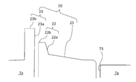
- FIG. 5 is a perspective view showing a state in the vicinity of a protrusion in the intraocular lens insertion device according to the embodiment of the present invention.
- FIG. 6 is a side view showing the vicinity of the protrusion in the intraocular lens insertion device according to the embodiment of the present invention when viewed from Y1 to Y2.
- FIG. 7 is a schematic cross-sectional view showing the movement of the front support portion (cross-sectional view) with respect to the protrusion portion in the intraocular lens insertion device according to the embodiment of the present invention.
- the front support portion 42a comes into contact with the upright portion 22a of the step 22 in the protrusion 20.
- the step 22 is a step that goes upward, that is, a step in the shape of an ascending staircase.
- the front support portion 42a is folded back by contact with the step 22 and the front support portion 42a slides up the step 22 by the advance of the optical portion 41 (FIG. 7A). ⁇ (b) ⁇ (c)).
- the front support portion 42a goes up the step 22.
- the front support portion 42a rides on the step 22 and starts moving forward again toward the wall portion 23a in front of the step 22 (FIG. 7 (c) ⁇ (D)).
- the bending of the front support portion 42a is temporarily suppressed as compared with the case where the step 22 slides up.
- the protrusion 21 described in Patent Document 1 that bends the front support portion is a mere pin-shaped protrusion. Even if the pin-shaped protrusion can be regarded as a step, the wall 23a like the protrusion 20 of the present embodiment does not exist in front of the step. Further, although the other protrusions 52 and 80 described in Patent Document 1 have a concave curve when viewed forward from the lens mounting portion, 1 when viewed forward from the lens mounting portion. There is only a step step, and there is no wall 23a like the protrusion 20 of the present embodiment in front of the step.
- the specific embodiment of the protrusion 20 is not particularly limited as long as the above configuration (projection from the inner wall of the hollow body, step, wall) is satisfied.
- the protrusion 20 may protrude from the lower side to the upper side of the inner wall of the hollow body, and may have at least two steps upward when viewed from the front lens installation portion 11 toward the front.
- the number of steps toward the top is not particularly limited as long as it is two or more steps, but the timing is the above when it is two to four steps. It is preferable in terms of the ease of manufacturing the intraocular lens insertion device 1 while effectively shifting the lens.
- the intraocular lens 4 is compared with the protrusion described in Patent Document 1. There is no change in delaying the timing at which the tip of the front support portion 42a moves to the vicinity of the inner wall of the hollow body with respect to the timing at which the folded peripheral edge portion 41b of the optical portion 41 advances.
- the rearmost standing portion 22a of the step is tilted by 45 to 95 ° with respect to the traveling direction of the intraocular lens 4 when the upper side is positive and the lower side is negative.
- the inclination of the upper portion 22b on the step 22 is set in the range of -30 to 30 ° with respect to the traveling direction of the intraocular lens 4, which effectively shifts the above timing and improves the tacking accuracy. It is preferable because it is easier to improve.
- the wall 23a (the standing portion in the second step 23) arranged in front of the step 22 is arranged at an angle of 60 to 100 ° with respect to the traveling direction of the intraocular lens 4.
- the inclination of the upper portion 23b in the second step 23 is not particularly limited, but like the upper portion 22b in the first step 22, it is ⁇ 30 to 30 with respect to the traveling direction of the intraocular lens 4. It may be set in the range of 30 °.
- the step refers to the step 22 of the first step.
- the vertical distance of the rearmost upright portion 22a of the step 22 may be, for example, 0.3 to 1.5 mm, and the distance of the upper portion 22b of the step 22 in the front-rear direction is 0.2 to 1.5 mm.
- the vertical distance of the wall 23a may be, for example, 0.3 to 1.5 mm.
- the vertical distance of the upright portion of each step may be uniformly set to 0.3 to 1.5 mm. Under these conditions, the timing can be effectively shifted and the tacking accuracy can be easily improved.
- the vertical distance of the entire protrusion 20 is preferably 1.5 to 3.0 mm in consideration of the use of the intraocular lens insertion device 1.
- an ascending slope (inclination) 21 may be arranged behind the step 22.
- the front support portion 42a can be guided to the upright portion 22a of the step 22 to be brought into contact with the front support portion 42a when the intraocular lens 4 starts to move forward.
- the angle of the slope 21 is not particularly limited, but since it is the slope 21, it is preferably more than 0 ° and 45 ° or less with respect to the traveling direction of the intraocular lens.
- the slope 21 is a continuous surface with respect to the lower part of the inner wall of the hollow body, but some steps (for example, 0.1 mm or less in the vertical direction) are allowed. If there is a distance longer than that, it may be regarded as a step 22. In consideration of such a situation, the expression of at least two steps is used in this specification.
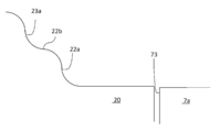
- FIG. 8 is a schematic side view showing the vicinity of the protrusion in the intraocular lens insertion device according to the modified example (No. 1) of the present invention when viewed from Y1 to Y2.
- the step 22 and the wall 23a are integrated is illustrated, but as shown in FIG. 8, they may be formed so as to be separated from each other.
- the separation width is too large, the front support portion 42a may fit and affect tacking. Therefore, even if they are separated, it is preferable that the separation width is smaller than the minimum cross-sectional width of the front support portion 42a.
- the protrusion 20 is provided in the case 62 and the protrusion insertion hole is provided in the intraocular lens insertion device 1.
- the case where 73 is provided is illustrated. That is, "the case 62 that fits the hollow body is further provided, and the protrusion 20 is provided in the case 62.
- An intraocular lens insertion device 1 in which a hole 73 into which the protrusion 20 can be fitted is formed in the hollow body. was illustrated in this embodiment.
- the protrusion 20 or a part thereof may be provided on the inner wall of the hollow body of the intraocular lens insertion device 1.
- FIG. 9 is a schematic side view showing the vicinity of the protrusion in the intraocular lens insertion device according to the modified example (No. 2) of the present invention when viewed from Y1 to Y2.
- the protrusion 20 projects from the upper side to the lower side of the inner wall of the hollow body
- the protrusion is stopped in front of the lower side of the inner wall and the front is viewed from the lens installation portion 11, the upper part
- the step 22 and the wall 23a toward the surface may be arranged so as to hang from above the inner wall of the hollow body.
- the protrusion 20 may be projected from the side of the inner wall of the hollow body.
- the tacking accuracy can be further improved by chamfering between the rearmost standing portion 22a and the upper portion 22b of the step 22, that is, the corner portion of the stairs.
- the chamfering mode is not particularly limited, and the corners may be cut out to be flattened or rounded as shown in FIGS. 5 and 6.
- FIG. 10 is a schematic side view showing the vicinity of the protrusion in the intraocular lens insertion device according to the modified example (No. 3) of the present invention when viewed from Y1 to Y2.
- the front support portion 42a is bent and slid up. Occurs effectively.
- the front support portion 42a is above the portion 22b. Bending is temporarily suppressed.
- the degree of risk that the front support portion 42a may enter between the outer surface of the optical portion 41 and the inner wall of the intraocular lens insertion device 1 may increase. It has also been clarified by the investigation of the present inventor that it changes. The configuration that reflects that finding is as follows. "It further has the intraocular lens 4. The optical portion 41 of the intraocular lens 4 and the proximal end sides of the support portions 42a and 42b are made of a soft material. The optical portion 41 of the intraocular lens 4 is an intraocular lens insertion device having an effective optical portion 41a that performs an optical function and a flat peripheral portion 41b arranged around the effective optical portion 41a. "
- the aspect of the protrusion 20 according to the present embodiment has been specifically specified.
- the technical idea of the present invention is that the tip of the front support portion 42a is in the vicinity of the inner wall of the intraocular lens insertion device 1 with respect to the timing when the folded peripheral edge portion 41b of the optical portion 41 of the intraocular lens 4 advances. The purpose is to delay the timing of movement.
- Expressing the present invention as a technical idea has the following structure. "An intraocular lens insertion device 1 for inserting an intraocular lens 4 having an optical unit 41 having an optical function and support portions 42a and 42b extending from the optical unit 41 into the eye.
- the front support portion 42a which is one of the support portions 42a and 42b, has a protrusion 20 that bends the front support portion 42a in contact with the front support portion 42a.
- the protrusion 20 is an intraocular lens insertion device having a holding portion that temporarily suppresses the progress of bending of the front support portion 42a by holding the front support portion 42a when the intraocular lens 4 is folded. 1. "
- the preferred example when the aspect of the protrusion 20 according to the present embodiment described so far is specifically specified can be applied to the above configuration.
- the protrusion 20 in the previous paragraph corresponds to the step 22 and the wall 23a described so far.
- the holding portion of the protrusion 20 corresponds to the portion 22b above the step 22 and the wall 23a described above. That is, the front support portion 42a is temporarily held by temporarily fitting the front support portion 42a between the portion 22b above the step 22 and the wall 23a.
- the holding is only temporary, and when the intraocular lens 4 is further advanced, the same phenomenon as the step 22 of the first step occurs, that is, the front support portion 42a slides up with respect to the wall 23a and is supported forward. The degree of bending of the portion 42a starts to increase again.
- the protrusion 20 is not limited to the steps 22 and 23.
- the holding portion is not limited to the portion 22b above the step 22 and the wall 23a in front of the portion 22b.
- the protrusion 20 has a first contact portion that bends the front support portion 42a by abutting with the front support portion 42a when the intraocular lens 4 is advanced by the advance member, and the first contact portion. It has the holding portion arranged in front of the contact portion and has the holding portion. The holding portion is arranged in front of the support portion receiving portion that supports the front support portion 42a after the front support portion 42a is separated from the first contact portion, and the support portion receiving portion.
- An intraocular lens insertion device 1 having a second contact portion that comes into contact with the front support portion 42a while being supported by.
- the correspondence between the first contact portion, the support portion receiving portion, and the second contact portion is arranged as follows.
- the upright portion 22a of the step 22 in FIGS. 5 to 10 corresponds to the first contact portion.
- the portion 22b above the step 22 in FIGS. 5 to 10 corresponds to the support portion receiving portion.
- the second contact portion corresponds to the wall 23a arranged in front of the step 22 in FIGS. 5 to 10.
- the protrusion described in Patent Document 1 is simply a one-step step when viewed in the traveling direction of the intraocular lens.
- the bending proceeds continuously.
- the front support portion 42a climbs up the step, the progress of bending is suppressed at the moment when the front support portion 42a climbs up, but at that time, the tip of the front support portion 42a is already on the optical portion 40 of the intraocular lens 4.
- the present inventor has found that the inner wall of the hollow body may be reached before the peripheral edge portion 41b. In that case, the front support portion 42a is inserted between the outer surface opposite to the inner surface of the optical portion 40 and the inner wall of the intraocular lens insertion device.
- the front support portion 42a is supported by the support portion receiving portion and advances to come into contact with the second contact portion, and then forward again.
- the degree of bending of the support portion 42a increases.
- the expression "holding portion that temporarily suppresses the progress of bending” is used in the above configuration. This means that a discontinuous change with a decrease in the degree of bending is brought about at least twice.
- the tip of the front support portion 42a is a hollow body with respect to the timing when the peripheral portion 41b of the folded intraocular lens advances. It is possible to delay the timing of moving to the vicinity of the inner wall of the lens. As a result, it is possible to improve the accuracy of tacking.
- Intraocular lens inserter 5 ... Insertion device body 6 ... Slider 7 ... Insert tube 7a ... Insert tube body 7b ... Nozzle part 7c ... Injection hole 8 ... Rotating member 9 ... Plunger 11 ... Lens installation part 11a ... Bottom part 11b ... Lens receiving portion 11c ... Lens guide portion 73 ... Protrusion insertion hole 62 ... Case 20 ... Protrusion 21 ... Slope 22 ... (1st step) Step 22a ... (1st step) Upright part 22b ... (1st step) Step above step 23 ... (2nd step) ) Step 23a ... (2nd step) Wall 23b ... (2nd step) Step above 75 ... Bottom plate 76 ... U-shaped wall 4 ... Intraocular lens 41 ... Optical part 41a ... Effective optical part 41b ... Peripheral part 42a ... Front support part 42b ... Rear support part
Landscapes
- Health & Medical Sciences (AREA)
- Ophthalmology & Optometry (AREA)
- Public Health (AREA)
- Life Sciences & Earth Sciences (AREA)
- Veterinary Medicine (AREA)
- Engineering & Computer Science (AREA)
- Biomedical Technology (AREA)
- Heart & Thoracic Surgery (AREA)
- Vascular Medicine (AREA)
- General Health & Medical Sciences (AREA)
- Animal Behavior & Ethology (AREA)
- Oral & Maxillofacial Surgery (AREA)
- Cardiology (AREA)
- Transplantation (AREA)
- Nuclear Medicine, Radiotherapy & Molecular Imaging (AREA)
- Surgery (AREA)
- Prostheses (AREA)
Abstract
Description
本発明の第1の態様は、
光学機能を有する光学部と前記光学部から延在する支持部とを有する眼内レンズを眼内に挿入する眼内レンズ挿入器具であって、
前記眼内レンズが設置される中空体の内壁に沿って前記眼内レンズを前進させることにより前記光学部の内面を内側にして折り畳まれた前記眼内レンズを前記中空体の外に放出する際に、前記支持部のうちの一つであって前方に配置された前方支持部に当接させて前記前方支持部を折り曲げる突起部を有し、
前記突起部は、前記眼内レンズの折り畳みの際に、前記前方支持部の保持により前記前方支持部の折り曲げの進行を一時的に抑制する保持部を有する、眼内レンズ挿入器具である。
挿入器具本体である前記中空体と、
前記中空体の内部に設けられるレンズ設置部と、
前記レンズ設置部に配置される前記眼内レンズを前進させる前進部材と、
前記レンズ設置部より前方に配置され且つ前記中空体の内壁から突出する前記突起部と、
前記中空体の前方先端部に配置される挿入筒と、を有し、
前記挿入筒は、中空の挿入筒本体と、管状のノズル部とを有し、
前記突起部は、前記前進部材により前記眼内レンズが前進する際に、前記前方支持部と当接することにより前記前方支持部を折り曲げる第1当接部と、前記第1当接部の前方に配置される前記保持部とを有し、
前記保持部は、前記前方支持部が前記第1当接部から離れた後に前記前方支持部を支える支持部受け部と、前記支持部受け部の前方に配置され且つ前記支持部受け部にて支えられながら前記前方支持部と当接する第2当接部と、を有する。
前記第1当接部と前記保持部との間は面取りされている。
光学部と前記光学部から延在する支持部とを有する眼内レンズを眼内に挿入する眼内レンズ挿入器具であって、
前記眼内レンズの光軸方向を上下方向として前記眼内レンズが載置されるレンズ設置部を有する中空体と、
前記中空体の内壁から突出し、且つ、前記レンズ設置部から前方に向かって見た時に少なくとも上方に向かう1段の段差と該段差の前方に配置された壁とを有する突起部と、を有する、眼内レンズ挿入器具である。
前記突起部は、前記中空体の内壁の下方から上方へと突出し、且つ、前記レンズ設置部から前方に向かって見た時に少なくとも上方に向かう2段の段差を有する。
前記突起部における最も後方側にスロープが配置される。
前記中空体と嵌合するケースを更に有し、
前記突起部は前記ケースに設けられており、
前記中空体には、前記突起部を嵌合可能な孔が形成される。
前記眼内レンズを更に有し、
前記眼内レンズの前記光学部および前記支持部の基端側は軟質材料により構成され、
前記眼内レンズの前記光学部は、光学機能を奏する有効光学部と、前記有効光学部の周囲に配置され且つ平板状の周縁部とを有する。
図1は、本発明の実施形態に係る眼内レンズ挿入器具の外観の構成例を示す斜視図である。
図2は、本発明の実施形態に係る挿入器具本体の先端部分の構造および配置を示す斜視図である。
なお、本願図1、図2は、WO2018/003854号公報の図1、図6と、眼内レンズ4以外は構成が類似する。そのため、本願図2に記載の符号のうち本明細書に記載のない符号はWO2018/003854号公報に記載の説明の通りである。
「挿入器具本体5である前記中空体と、
前記中空体の内部に設けられるレンズ設置部11と、
前記レンズ設置部11に配置される前記眼内レンズ4を前進させる前進部材(スライダ6またはプランジャ9と連結したロッド)と、
前記レンズ設置部11より前方に配置され且つ前記中空体の内壁から突出する前記突起部20と、
前記中空体の前方先端部に配置される挿入筒7と、を有し、
前記挿入筒7は、中空の挿入筒本体7aと、管状のノズル部7bとを有する、眼内レンズ挿入器具1。」
ケースの構成としては、例えば本出願人による特許文献1の構成を採用して差し支えない。ケースの構成に関し、以下に記載が無い内容は、特許文献1の構成を採用するものとし、特許文献1の記載は本明細書に全て記載されているものとする。
図4は、本発明の実施形態に係る眼内レンズ挿入器具をケースに装着した様子を示す斜視図である。
その一方、眼内レンズ4の放出の際に上述のように前方支持部42aの先端が中空体の内壁と光学部41の外面との間に入り込むという課題が生じる。この課題を解決すべく、本実施形態においては突起部20を以下の態様とした眼内レンズ挿入器具1を使用する。
「光学部41と前記光学部41から延在する支持部42a,42bとを有する眼内レンズ4を眼内に挿入する眼内レンズ挿入器具1であって、
前記眼内レンズ4の光軸方向を上下方向として前記眼内レンズ4が載置されるレンズ設置部11を有する中空体と、
前記中空体の内壁から突出し、且つ、前記レンズ設置部11から前方に向かって見た時に少なくとも上方に向かう1段の段差22(22a,22b)と該段差の前方に壁23aとを有する突起部20と、を有する、眼内レンズ挿入器具1。」
図6は、本発明の実施形態に係る眼内レンズ挿入器具における突起部の近傍の様子を示す、Y1からY2方向に向かって見た時の側面図である。
図7は、本発明の実施形態に係る眼内レンズ挿入器具における突起部に対する前方支持部(断面視)の動きを示す概略断面図である。
なお、本実施形態では該段差22と該壁23aとが一体となっている場合を例示するが、図8に示すように、互いに離間して形成されていてもよい。但し、離間幅が大きすぎると前方支持部42aが嵌ってタッキングに影響をもたらす可能性がある。そのため、離間させるにしても、前方支持部42aの断面最小幅よりも小さい離間幅とするのが好ましい。
つまり、「前記中空体と嵌合するケース62を更に有し、 前記突起部20は前記ケース62に設けられており、
前記中空体には、前記突起部20を嵌合可能な孔73が形成された、眼内レンズ挿入器具1。」を本実施形態では例示した。
その一方、眼内レンズ挿入器具1の中空体の内壁に対して該突起部20またはその一部を設けてももちろん構わない。
図9は、本発明の変形例(その2)に係る眼内レンズ挿入器具における突起部の近傍の様子を示す、Y1からY2方向に向かって見た時の概略側面図である。
例えば、図9に示すように、中空体の内壁の上方から下方へと突起部20が突出する場合、内壁下方手前で突出を止めつつ、レンズ設置部11から前方を見たときに、上記上方に向かう段差22および壁23aが、中空体の内壁上方からぶら下がる形で配置されても構わない。同様に、中空体の内壁側方から突起部20を突出させても構わない。
図10は、本発明の変形例(その3)に係る眼内レンズ挿入器具における突起部の近傍の様子を示す、Y1からY2方向に向かって見た時の概略側面図である。
図10の場合、起立部分22aの部分および壁23aの部分における曲面の接線が、眼内レンズ4の進行方向に対して例えば60~100°傾いたときに前方支持部42aの折れ曲がりと摺り上りが効果的に生じる。また、段差22における上の部分22bに対応する部分の接線の傾きが、眼内レンズ4の進行方向に対して例えば-30~30°であるときに、前方支持部42aが該部分22bの上に乗り、折れ曲がりが一時的に抑制される。
「前記眼内レンズ4を更に有し、
前記眼内レンズ4の前記光学部41および前記支持部42a,42bの基端側は軟質材料により構成され、
前記眼内レンズ4の前記光学部41は、光学機能を奏する有効光学部41aと、前記有効光学部41aの周囲に配置され且つ平板状の周縁部41bとを有する、眼内レンズ挿入器具。」
「光学機能を有する光学部41と前記光学部41から延在する支持部42a,42bとを有する眼内レンズ4を眼内に挿入する眼内レンズ挿入器具1であって、
前記眼内レンズ4が設置される中空体の内壁に沿って前記眼内レンズ4を前進させることにより前記光学部41の内面を内側にして折り畳まれた前記眼内レンズ4を前記中空体の外に放出する際に、前記支持部42a,42bのうちの一つであって前方に配置された前方支持部42aに当接させて前記前方支持部42aを折り曲げる突起部20を有し、
前記突起部20は、前記眼内レンズ4の折り畳みの際に、前記前方支持部42aの保持により前記前方支持部42aの折り曲げの進行を一時的に抑制する保持部を有する、眼内レンズ挿入器具1。」
なお、これまでに述べてきた本実施形態に係る突起部20の態様を具体的に特定した際の好適例は、上記構成にも適用可能である。
「前記突起部20は、前記前進部材により前記眼内レンズ4が前進する際に、前記前方支持部42aと当接することにより前記前方支持部42aを折り曲げる第1当接部と、前記第1当接部の前方に配置される前記保持部とを有し、
前記保持部は、前記前方支持部42aが前記第1当接部から離れた後に前記前方支持部42aを支える支持部受け部と、前記支持部受け部の前方に配置され且つ前記支持部受け部にて支えられながら前記前方支持部42aと当接する第2当接部と、を有する、眼内レンズ挿入器具1。」
第1当接部としては、図5~図10における段差22の起立部分22aが該当する。
支持部受け部としては、図5~図10における段差22の上の部分22bが該当する。
第2当接部としては、図5~図10における段差22の前方に配置された壁23aが該当する。
5…挿入器具本体
6…スライダ
7…挿入筒
7a…挿入筒本体
7b…ノズル部
7c…注入孔
8…回転部材
9…プランジャ
11…レンズ設置部
11a…底面部
11b…レンズ受け部
11c…レンズガイド部
73…突起挿入孔
62…ケース
20…突起部
21…スロープ
22…(1段目の)段差
22a…(1段目の)段差の起立部分
22b…(1段目の)段差の上の部分
23…(2段目の)段差
23a…(2段目の)壁
23b…(2段目の)段差の上の部分
75…底板部
76…U字状の壁部
4…眼内レンズ
41…光学部
41a…有効光学部
41b…周縁部
42a…前方支持部
42b…後方支持部
Claims (8)
- 光学機能を有する光学部と前記光学部から延在する支持部とを有する眼内レンズを眼内に挿入する眼内レンズ挿入器具であって、
前記眼内レンズが設置される中空体の内壁に沿って前記眼内レンズを前進させることにより前記光学部の内面を内側にして折り畳まれた前記眼内レンズを前記中空体の外に放出する際に、前記支持部のうちの一つであって前方に配置された前方支持部に当接させて前記前方支持部を折り曲げる突起部を有し、
前記突起部は、前記眼内レンズの折り畳みの際に、前記前方支持部の保持により前記前方支持部の折り曲げの進行を一時的に抑制する保持部を有する、眼内レンズ挿入器具。 - 挿入器具本体である前記中空体と、
前記中空体の内部に設けられるレンズ設置部と、
前記レンズ設置部に配置される前記眼内レンズを前進させる前進部材と、
前記レンズ設置部より前方に配置され且つ前記中空体の内壁から突出する前記突起部と、
前記中空体の前方先端部に配置される挿入筒と、を有し、
前記挿入筒は、中空の挿入筒本体と、管状のノズル部とを有し、
前記突起部は、前記前進部材により前記眼内レンズが前進する際に、前記前方支持部と当接することにより前記前方支持部を折り曲げる第1当接部と、前記第1当接部の前方に配置される前記保持部とを有し、
前記保持部は、前記前方支持部が前記第1当接部から離れた後に前記前方支持部を支える支持部受け部と、前記支持部受け部の前方に配置され且つ前記支持部受け部にて支えられながら前記前方支持部と当接する第2当接部と、を有する、請求項1に記載の眼内レンズ挿入器具。 - 前記第1当接部と前記保持部との間は面取りされている、請求項2に記載の眼内レンズ挿入器具。
- 光学部と前記光学部から延在する支持部とを有する眼内レンズを眼内に挿入する眼内レンズ挿入器具であって、
前記眼内レンズの光軸方向を上下方向として前記眼内レンズが載置されるレンズ設置部を有する中空体と、
前記中空体の内壁から突出し、且つ、前記レンズ設置部から前方に向かって見た時に少なくとも上方に向かう1段の段差と該段差の前方に配置された壁とを有する突起部と、を有する、眼内レンズ挿入器具。 - 前記突起部は、前記中空体の内壁の下方から上方へと突出し、且つ、前記レンズ設置部から前方に向かって見た時に少なくとも上方に向かう2段の段差を有する、請求項4に記載の眼内レンズ挿入器具。
- 前記突起部における最も後方側にスロープが配置された、請求項1~5のいずれかに記載の眼内レンズ挿入器具。
- 前記中空体と嵌合するケースを更に有し、
前記突起部は前記ケースに設けられており、
前記中空体には、前記突起部を嵌合可能な孔が形成された、請求項1~6のいずれかに記載の眼内レンズ挿入器具。 - 前記眼内レンズを更に有し、
前記眼内レンズの前記光学部および前記支持部の基端側は軟質材料により構成され、
前記眼内レンズの前記光学部は、光学機能を奏する有効光学部と、前記有効光学部の周囲に配置され且つ平板状の周縁部とを有する、請求項1~7のいずれかに記載の眼内レンズ挿入器具。
Priority Applications (4)
| Application Number | Priority Date | Filing Date | Title |
|---|---|---|---|
| EP19919001.8A EP3939542A4 (en) | 2019-03-13 | 2019-12-23 | TOOL FOR INSERTING AN INTRAOCULAR LENS |
| CN201980093397.4A CN113498333B (zh) | 2019-03-13 | 2019-12-23 | 眼内透镜插入器具 |
| KR1020217030550A KR102801136B1 (ko) | 2019-03-13 | 2019-12-23 | 안내 렌즈 삽입 기구 |
| US17/435,762 US12478467B2 (en) | 2019-03-13 | 2019-12-23 | Intraocular lens injector |
Applications Claiming Priority (2)
| Application Number | Priority Date | Filing Date | Title |
|---|---|---|---|
| JP2019-045673 | 2019-03-13 | ||
| JP2019045673A JP7327956B2 (ja) | 2019-03-13 | 2019-03-13 | 眼内レンズ挿入器具 |
Publications (1)
| Publication Number | Publication Date |
|---|---|
| WO2020183856A1 true WO2020183856A1 (ja) | 2020-09-17 |
Family
ID=72426419
Family Applications (1)
| Application Number | Title | Priority Date | Filing Date |
|---|---|---|---|
| PCT/JP2019/050238 Ceased WO2020183856A1 (ja) | 2019-03-13 | 2019-12-23 | 眼内レンズ挿入器具 |
Country Status (6)
| Country | Link |
|---|---|
| US (1) | US12478467B2 (ja) |
| EP (1) | EP3939542A4 (ja) |
| JP (1) | JP7327956B2 (ja) |
| KR (1) | KR102801136B1 (ja) |
| CN (1) | CN113498333B (ja) |
| WO (1) | WO2020183856A1 (ja) |
Families Citing this family (4)
| Publication number | Priority date | Publication date | Assignee | Title |
|---|---|---|---|---|
| WO2008149795A1 (ja) | 2007-05-30 | 2008-12-11 | Hoya Corporation | 眼内レンズ挿入器具 |
| WO2018003853A1 (ja) | 2016-06-28 | 2018-01-04 | Hoya株式会社 | 眼内レンズ挿入器 |
| JP7162443B2 (ja) | 2018-05-16 | 2022-10-28 | Hoya株式会社 | 容器付き眼内リング挿入器 |
| JP7162445B2 (ja) | 2018-05-25 | 2022-10-28 | Hoya株式会社 | 眼内レンズ挿入器 |
Citations (4)
| Publication number | Priority date | Publication date | Assignee | Title |
|---|---|---|---|---|
| JP5254669B2 (ja) | 2008-06-05 | 2013-08-07 | Hoya株式会社 | 眼内レンズ挿入器具及びカートリッジ |
| JP2014079630A (ja) * | 2013-11-25 | 2014-05-08 | Kowa Company Ltd | 眼内レンズ挿入器具 |
| JP2017055940A (ja) * | 2015-09-16 | 2017-03-23 | Hoya株式会社 | 眼内レンズ挿入器具 |
| WO2018003854A1 (ja) | 2016-06-28 | 2018-01-04 | Hoya株式会社 | 眼内レンズ挿入器 |
Family Cites Families (302)
| Publication number | Priority date | Publication date | Assignee | Title |
|---|---|---|---|---|
| US2761446A (en) | 1955-03-30 | 1956-09-04 | Chemical Specialties Co Inc | Implanter and cartridge |
| GB999506A (en) | 1960-11-02 | 1965-07-28 | Engis Ltd | Improvements in syringes for dispensing paste or the like |
| US4205747A (en) | 1978-09-05 | 1980-06-03 | Cilco, Inc. | Lens storage device |
| US4269307A (en) | 1979-08-09 | 1981-05-26 | Iolab Corporation | Intraocular lens storage assembly |
| US4573998A (en) | 1982-02-05 | 1986-03-04 | Staar Surgical Co. | Methods for implantation of deformable intraocular lenses |
| US4423809A (en) | 1982-02-05 | 1984-01-03 | Staar Surgical Company, Inc. | Packaging system for intraocular lens structures |
| US4702244A (en) | 1982-02-05 | 1987-10-27 | Staar Surgical Company | Surgical device for implantation of a deformable intraocular lens |
| US4608049A (en) | 1982-06-28 | 1986-08-26 | Kelman Charles D | Intraocular lens and method of inserting an intraocular lens into an eye |
| US4634423A (en) | 1984-04-30 | 1987-01-06 | Bailey Jr Paul F | Ophthalmological method and instrument for implantation of posterior chamber intraocular lens |
| US4787904A (en) | 1984-07-06 | 1988-11-29 | Severin Sanford L | Hydrophillic intraocular lens |
| US4699140A (en) | 1985-07-10 | 1987-10-13 | Iolab Corporation | Instrument for inserting an intraocular lens |
| US4681102A (en) | 1985-09-11 | 1987-07-21 | Bartell Michael T | Apparatus and method for insertion of an intra-ocular lens |
| US4715373A (en) | 1985-09-27 | 1987-12-29 | Mazzocco Thomas R | Devices for implantation of deformable intraocular lens structures |
| US4750498A (en) | 1986-02-21 | 1988-06-14 | Coopervision, Inc. | Method and tool for inserting an intraocular lens |
| DE3610925C2 (de) | 1986-03-24 | 1994-11-03 | Michael Ulrich Prof D Dardenne | Vorrichtung zum Falten einer insbesondere mit zwei seitlichen Kunststoffhaptikplatten versehenen, implantierbaren Intraokularlinse und zum Einbringen der gefalteten Intraokularlinse in das Auge |
| US4697697A (en) | 1986-08-18 | 1987-10-06 | Coopervision, Inc. | Method and apparatus for packaging an intraocular lens |
| JPS63197453A (ja) | 1986-11-07 | 1988-08-16 | ザ・クーパー・カンパニー・インク | 圧縮性眼内レンズを眼に挿入する器具および方法 |
| US4919130A (en) | 1986-11-07 | 1990-04-24 | Nestle S.A. | Tool for inserting compressible intraocular lenses into the eye and method |
| US4747404A (en) | 1986-11-10 | 1988-05-31 | Kresge Eye Institute Of Wayne State University | Foldable intraocular lens inserter |
| US4763650A (en) | 1987-01-20 | 1988-08-16 | Hauser Stephen G | Instrument for inserting a deformable lens into the eye |
| US4810249A (en) | 1987-03-12 | 1989-03-07 | Habley Medical Technology Corp. | Linear and Vernier-type syringe |
| US4994028A (en) | 1987-03-18 | 1991-02-19 | Endocon, Inc. | Injector for inplanting multiple pellet medicaments |
| US5176686A (en) | 1987-03-26 | 1993-01-05 | Poley Brooks J | Apparatus for packaging, folding, rigidifying and inserting an intraocular lens |
| US4769034A (en) | 1987-03-26 | 1988-09-06 | Poley Brooks J | Folded intraocular lens, method of implanting folded intraocular lens |
| US4988352A (en) | 1987-03-26 | 1991-01-29 | Poley Brooks J | Method and apparatus for folding, freezing and implanting intraocular lens |
| US4819631A (en) | 1987-03-26 | 1989-04-11 | Poley Brooks J | Folded intraocular lens, method of implanting it, retainer, and apparatus for folding lens |
| US4781719A (en) | 1987-07-28 | 1988-11-01 | Kelman Charles D | Method of inserting an intraocular lens into an eye |
| US4759359A (en) | 1987-08-31 | 1988-07-26 | Allergan, Inc. | Lens implantation instrument |
| US4834094A (en) | 1987-10-07 | 1989-05-30 | Patton Medical Technologies, Inc. | "Canoe" apparatus for inserting intra-ocular lens into the eye |
| US4765329A (en) | 1987-10-19 | 1988-08-23 | Cumming, Redwitz & Wilson, Inc. | Intraocular lens insertion instrument |
| US4880000A (en) | 1987-12-15 | 1989-11-14 | Iolab Corporation | Lens insertion instrument |
| US4934363A (en) | 1987-12-15 | 1990-06-19 | Iolab Corporation | Lens insertion instrument |
| US4836201A (en) | 1988-03-24 | 1989-06-06 | Patton Medical Technologies, Inc. | "Envelope" apparatus for inserting intra-ocular lens into the eye |
| US4862885A (en) | 1988-05-25 | 1989-09-05 | Cumming J Stuart | Instrument for inserting a deformable intraocular lens into the eye |
| AU623934B2 (en) | 1988-10-07 | 1992-05-28 | Ioptex Research Inc | Intraocular lens insertion instrument |
| US4976716A (en) | 1989-01-23 | 1990-12-11 | Cumming J Stuart | Intraocular lens insertion device |
| US5066297A (en) | 1989-01-23 | 1991-11-19 | Cumming J Stuart | Intraocular lens insertion device |
| US4955889A (en) | 1989-02-06 | 1990-09-11 | Allergan, Inc. | Apparatus for inserting a lens into an eye and method for using same |
| US5222972A (en) | 1989-04-12 | 1993-06-29 | Allergan, Inc. | Small incision intraocular lens insertion apparatus |
| US5098439A (en) | 1989-04-12 | 1992-03-24 | Allergan, Inc. | Small incision intraocular lens insertion apparatus |
| US5171241A (en) | 1989-06-09 | 1992-12-15 | Ioptex Research Inc. | Device for folding an intraocular lens and holding it in the folded state |
| DE4030492C1 (ja) | 1990-09-26 | 1991-09-05 | Adatomed Pharmazeutische Und Medizintechnische Gesellschaft Mbh, 8000 Muenchen, De | |
| DE4039119C1 (ja) | 1990-12-07 | 1991-09-05 | Dieter Dr.Med. 8904 Friedberg De Klaas | |
| DE4108303C2 (de) | 1991-03-14 | 1993-11-04 | Adatomed Pharma & Med | Verfahren und vorrichtung zum einbringen einer gummielastischen intraokularlinse in ein implantationswerkzeug |
| DE4110278A1 (de) | 1991-03-28 | 1992-10-01 | Geuder Hans Gmbh | Augenchirurgisches instrument zum implantieren von hinterkammer-weichlinsen |
| US5123905A (en) | 1991-06-07 | 1992-06-23 | Kelman Charles D | Intraocular lens injector |
| JPH0732791B2 (ja) | 1991-06-13 | 1995-04-12 | キヤノンスター株式会社 | 眼内レンズの移植器具 |
| JPH0779825B2 (ja) | 1991-06-13 | 1995-08-30 | キヤノンスター株式会社 | 眼内レンズの移植器具 |
| JPH0779826B2 (ja) | 1991-06-14 | 1995-08-30 | キヤノンスター株式会社 | 眼内レンズの移植器具 |
| US5178622A (en) | 1991-11-01 | 1993-01-12 | Lehner Ii Robert H | Instrument for implanting a soft intraocular lens |
| US5259395A (en) | 1992-01-15 | 1993-11-09 | Siemens Pacesetter, Inc. | Pacemaker lead with extendable retractable lockable fixing helix |
| US5190552A (en) | 1992-02-04 | 1993-03-02 | Kelman Charles D | Slotted tube injector for an intraocular lens |
| US5395378A (en) | 1992-05-18 | 1995-03-07 | Henry H. McDonald | Eye implantable lens haptics insertion and twist apparatus |
| US5571113A (en) | 1992-05-18 | 1996-11-05 | Henry H. McDonald | Surgical probe with tips for plastic lens implantation in the eye |
| US5242450A (en) | 1992-05-18 | 1993-09-07 | Henry H. McDonald | Eye implantable lens haptics twist apparatus |
| US5304182A (en) | 1992-09-23 | 1994-04-19 | Kabi Pharmacia Ophthalmics, Inc. | Apparatus and method for curling and inserting flexible intraocular lenses |
| US6712848B1 (en) | 1992-09-30 | 2004-03-30 | Staar Surgical Company, Inc. | Deformable intraocular lens injecting apparatus with transverse hinged lens cartridge |
| US6506195B2 (en) | 1992-09-30 | 2003-01-14 | Staar Surgical Company, Inc. | Deformable intraocular lens insertion system |
| US6059791A (en) | 1992-09-30 | 2000-05-09 | Staar Surgical Company, Inc. | Deformable intraocular lens injection system, and method thereof |
| US5616148A (en) | 1992-09-30 | 1997-04-01 | Staar Surgical Company, Inc. | Transverse hinged deformable intraocular lens injecting apparatus |
| US6022358A (en) | 1992-09-30 | 2000-02-08 | Staar Surgical Company, Inc. | Deformable intraocular lens injecting device |
| US5928245A (en) | 1992-09-30 | 1999-07-27 | Staar Surgical Company, Inc. | Deformable intraocular lens injecting apparatus with transverse hinged lens cartridge |
| PT723429E (pt) | 1992-09-30 | 2002-09-30 | Vladimir Feingold | Sistema de insercao de lentes intra-oculares |
| US5772666A (en) | 1992-09-30 | 1998-06-30 | Staar Surgical Company, Inc. | Deformable intraocular lens injecting apparatus with deformable tip plunger |
| US5728102A (en) | 1992-09-30 | 1998-03-17 | Staar Surgical Company, Inc. | Disposable intraocular lens insertion system |
| US6001107A (en) | 1992-09-30 | 1999-12-14 | Staar Surgical Company, Inc. | Deformable intraocular lens injecting apparatus |
| US5941886A (en) | 1992-09-30 | 1999-08-24 | Staar Surgical Company, Inc. | Hingeless lens cartridges for insertion of deformable intraocular lens |
| US5876440A (en) | 1992-09-30 | 1999-03-02 | Staar Surgical Company, Inc. | Methods of implantation of deformable intraocular lens |
| US5860984A (en) | 1992-09-30 | 1999-01-19 | Staar Surgical Company, Inc. | Spring biased deformable intraocular injecting apparatus |
| US6406481B2 (en) | 1992-09-30 | 2002-06-18 | Starr Surgical Company, Inc. | Method preloading a deformable intraocular lens into injecting apparatus for storage and/or shipment |
| US5620450A (en) | 1992-09-30 | 1997-04-15 | Staar Surgical Company, Inc. | Transverse hinged deformable intraocular lens injecting apparatus |
| US5807400A (en) | 1992-09-30 | 1998-09-15 | Staar Surgical Company, Inc. | Deformable intraocular lens insertion system |
| US6056757A (en) | 1992-09-30 | 2000-05-02 | Staar Surgical Company, Inc. | Implantation device with deformable nozzle tip for implanting a deformable intraocular lens |
| US5499987A (en) | 1992-09-30 | 1996-03-19 | Staar Surgical Company | Deformable intraocular lens cartridge |
| US5281227A (en) | 1992-11-09 | 1994-01-25 | Allergan, Inc. | Lens case with IOL folding device |
| US5275604A (en) | 1992-12-03 | 1994-01-04 | Kabi Pharmacia Ophthalmics, Inc. | Contoured duct apparatus and method for insertion of flexible intraocular lens |
| US5653715A (en) | 1993-03-09 | 1997-08-05 | Chiron Vision Corporation | Apparatus for preparing an intraocular lens for insertion |
| US5425734A (en) | 1993-07-02 | 1995-06-20 | Iovision, Inc. | Intraocular lens injector |
| US5468246A (en) | 1993-07-02 | 1995-11-21 | Iovision, Inc. | Intraocular lens injector |
| JP3459664B2 (ja) | 1993-07-15 | 2003-10-20 | キヤノンスター株式会社 | 変形可能な眼内レンズの挿入器具 |
| SE9303568D0 (sv) | 1993-10-29 | 1993-10-29 | Kabi Pharmacia Ab | Improvements in injection devices |
| US5582613A (en) | 1993-11-18 | 1996-12-10 | Allergan | Apparatus and methods for controlled insertion of intraocular lenses |
| US5702402A (en) | 1994-04-29 | 1997-12-30 | Allergal | Method and apparatus for folding of intraocular lens |
| US5584304A (en) | 1993-11-18 | 1996-12-17 | Allergan, Inc. | Method of inserting an IOL using a forceps inside a folding tube |
| WO1995013766A1 (en) | 1993-11-18 | 1995-05-26 | Allergan, Inc. | Deformable lens insertion apparatus |
| AU1915595A (en) | 1994-02-09 | 1995-08-29 | Kabi Pharmacia Ophthalmics, Inc. | Rapid implantation of shape transformable optical lenses |
| US6174315B1 (en) | 1994-02-15 | 2001-01-16 | Staar Surgical Company, Inc. | Spring biased deformable intraocular injecting apparatus |
| US5578042A (en) | 1994-03-14 | 1996-11-26 | Cumming; J. Stuart | Ophthalmic kit and method for lens insertion |
| US5645534A (en) | 1994-06-24 | 1997-07-08 | Becton Dickinson And Company | Time of last injection indicator for medication delivery pen |
| JP3412106B2 (ja) | 1994-07-07 | 2003-06-03 | キヤノンスター株式会社 | 変形可能な眼内レンズの挿入器具 |
| JP3412107B2 (ja) | 1994-07-18 | 2003-06-03 | キヤノンスター株式会社 | 変形可能な眼内レンズの挿入器具 |
| US5454818A (en) | 1994-07-26 | 1995-10-03 | Alcon Laboratories, Inc. | Intraocular lens folder |
| EP1338254B1 (en) | 1994-08-05 | 2008-12-03 | Bausch & Lomb Incorporated | A method of packaging an intraocular lens |
| ATE245012T1 (de) | 1994-11-18 | 2003-08-15 | Vladimir Feingold | Einführungssystem für wegwerfbare intraokulare linsen |
| US5803925A (en) | 1995-01-17 | 1998-09-08 | Allergan | IOL insertion apparatus with covalently bonded lubricant |
| CN1185100A (zh) | 1995-03-14 | 1998-06-17 | 约翰·R·沃尔夫 | 柔性眼内晶状体注射系统 |
| US5643276A (en) | 1995-10-10 | 1997-07-01 | Allergan | Apparatus and method for providing desired rotational orientation to an intraocular lens |
| DE19544119A1 (de) | 1995-11-27 | 1997-05-28 | Wolfram Dr Wehner | Implantationswerkzeug zum Implantieren einer faltbaren, flexiblen Intraokularlinse |
| US5776138A (en) | 1996-01-26 | 1998-07-07 | Allergan | Apparatus and methods for IOL insertion |
| US5735858A (en) | 1996-01-26 | 1998-04-07 | Allergan | IOL insertion apparatus and method for using same |
| FR2749752B1 (fr) | 1996-06-17 | 1998-11-20 | Moria Sa | Dispositif de pliage et de maintien plie d'un implant intraoculaire souple |
| US6283975B1 (en) | 1996-07-10 | 2001-09-04 | Allergan Sales, Inc. | IOL insertion apparatus and method for making and using same |
| US5716364A (en) | 1996-07-10 | 1998-02-10 | Allergan | IOL insertion apparatus and method for making and using same |
| US6083230A (en) | 1997-07-30 | 2000-07-04 | Allergan | Method for making IOL insertion apparatus |
| US5766181A (en) | 1996-08-02 | 1998-06-16 | Staar Surgical Company, Inc. | Spring biased deformable intraocular injecting apparatus |
| US5876406A (en) | 1996-08-02 | 1999-03-02 | Staar Surgical Company, Inc. | Deformable intraocular lens injecting apparatus with transverse hinged lens cartridge |
| US5944725A (en) | 1996-09-26 | 1999-08-31 | Bausch & Lomb Surgical, Inc. | Method and apparatus for inserting a flexible membrane into an eye |
| US5810834A (en) | 1996-10-07 | 1998-09-22 | Chiron Vision Corporation | Tip formation for inserting a flexible membrane into an eye |
| US6503275B1 (en) | 1996-11-15 | 2003-01-07 | Medevec Licensing, B.V. | Ophthalmic lens insertion instrument and package |
| JP3226813B2 (ja) | 1996-12-13 | 2001-11-05 | トリンプ・インターナショナル・ジャパン株式会社 | 女性用衣類 |
| US5947975A (en) | 1997-03-07 | 1999-09-07 | Canon Staar Co., Inc. | Inserting device for deformable intraocular lens |
| US5919197A (en) | 1997-05-05 | 1999-07-06 | Surgical Concepts, Inc. | Insertion of multiple folded lens into the eye |
| JP3779819B2 (ja) | 1997-08-11 | 2006-05-31 | キヤノンスター株式会社 | 眼内挿入用レンズの挿入器具 |
| US5921966A (en) | 1997-08-11 | 1999-07-13 | Becton Dickinson And Company | Medication delivery pen having an improved clutch assembly |
| US6605093B1 (en) | 1997-10-24 | 2003-08-12 | Tekia, Inc. | Device and method for use with an ophthalmologic insertor apparatus |
| US5947974A (en) | 1997-12-09 | 1999-09-07 | Allergan | Folding device and method for an intraocular lens |
| US6050999A (en) | 1997-12-18 | 2000-04-18 | Keravision, Inc. | Corneal implant introducer and method of use |
| GB9801214D0 (en) | 1998-01-22 | 1998-03-18 | Duckworth & Kent Ltd | Lens injector |
| US5921989A (en) | 1998-02-12 | 1999-07-13 | Allergan | Lens protector for intraocular lens inserter |
| US6497708B1 (en) | 1998-05-11 | 2002-12-24 | Medevec Licensing, B.V. | Intraocular lens insertion instrument |
| US6371960B2 (en) | 1998-05-19 | 2002-04-16 | Bausch & Lomb Surgical, Inc. | Device for inserting a flexible intraocular lens |
| US6010510A (en) | 1998-06-02 | 2000-01-04 | Alcon Laboratories, Inc. | Plunger |
| US6143001A (en) | 1998-06-02 | 2000-11-07 | Alcon Laboratories, Inc. | Asymmetric intraocular lens injection cartridge |
| US6447520B1 (en) | 2001-03-19 | 2002-09-10 | Advanced Medical Optics, Inc. | IOL insertion apparatus with IOL engagement structure and method for using same |
| DE19904220C2 (de) | 1999-02-03 | 2001-08-30 | Helmut Binder | Injektor zum Falten und Einbringen einer Intraokularlinse, und Behälter zum Lagern und Transportieren des Injektors |
| FR2789890B1 (fr) | 1999-02-22 | 2002-01-18 | Lab Contactologie Appl Lca | Dispositif pour l'injection d'une lentille intra-oculaire en matiere souple |
| US6129733A (en) | 1999-04-15 | 2000-10-10 | Allergan Sales, Inc. | Apparatus for holding intraocular lenses and injectors, and methods for using same |
| US6386357B1 (en) | 1999-07-12 | 2002-05-14 | Hoya Healthcare Corporation | Soft intraocular lens-folding device and storage case |
| US6248111B1 (en) | 1999-08-06 | 2001-06-19 | Allergan Sales, Inc. | IOL insertion apparatus and methods for using same |
| US6699285B2 (en) | 1999-09-24 | 2004-03-02 | Scieran Technologies, Inc. | Eye endoplant for the reattachment of a retina |
| JP3728155B2 (ja) | 1999-10-05 | 2005-12-21 | キヤノンスター株式会社 | 眼内挿入用レンズの挿入システム |
| JP3944555B2 (ja) | 1999-10-06 | 2007-07-11 | キヤノンスター株式会社 | 眼内挿入用レンズの挿入システム |
| US6387101B1 (en) | 1999-10-22 | 2002-05-14 | Staar Surgical Company, Inc. | Deformable intraocular lens injecting apparatus and method |
| US6312433B1 (en) | 1999-10-22 | 2001-11-06 | Staar Surgical Company, Inc. | Deformable intraocular lens injecting apparatus and method |
| US6251114B1 (en) | 1999-10-29 | 2001-06-26 | Allergan Sales, Inc. | Rotatable IOL insertion apparatus and method for using same |
| FR2801192B1 (fr) | 1999-11-19 | 2002-08-09 | Corneal Ind | Anneau pour sac capsulaire et ensemble constitue par un tel anneau et son injecteur |
| SE9904338D0 (sv) | 1999-11-30 | 1999-11-30 | Pharmacia & Upjohn Ab | Intraocular lens implanter |
| JP2001259033A (ja) | 2000-03-17 | 2001-09-25 | Jms Co Ltd | 注射器 |
| US6283976B1 (en) | 2000-05-05 | 2001-09-04 | Allergan Sales Inc. | Intraocular lens implanting instrument |
| GB0011507D0 (en) | 2000-05-13 | 2000-06-28 | Duckworth & Kent Ltd | Ophthalmic lens injectors |
| FR2814360B1 (fr) | 2000-09-28 | 2002-12-27 | Corneal Ind | Injecteur d'implant intraoculaire souple |
| US6500181B1 (en) | 2000-10-17 | 2002-12-31 | Valdemar Portney | Instrument for folding and inserting anterior chamber intraocular lenses |
| US6471708B2 (en) * | 2000-12-21 | 2002-10-29 | Bausch & Lomb Incorporated | Intraocular lens and additive packaging system |
| US6899699B2 (en) | 2001-01-05 | 2005-05-31 | Novo Nordisk A/S | Automatic injection device with reset feature |
| US6540754B2 (en) | 2001-01-26 | 2003-04-01 | Advanced Medical Optics, Inc. | Apparatus and method for multiply folding and inserting an intraocular lens in an eye |
| US6554839B2 (en) | 2001-01-26 | 2003-04-29 | Advanced Medical Optics, Inc. | Stepped IOL insertion cartridge for inserting an intraocular lens in an eye |
| FR2822055B1 (fr) | 2001-03-16 | 2003-09-12 | Lab Contactologie Appl Lca | Injecteur pour lentille intraoculaire |
| WO2002080811A2 (en) | 2001-04-07 | 2002-10-17 | Glaukos Corporation | Glaucoma stent and methods thereof for glaucoma treatment |
| US6786911B2 (en) | 2001-05-25 | 2004-09-07 | Hoya Healthcare Corporation | Storage case having soft intraocular lens folding function |
| JP2002355268A (ja) | 2001-06-01 | 2002-12-10 | Nidek Co Ltd | 眼内レンズ挿入器具 |
| US6537283B2 (en) | 2001-08-17 | 2003-03-25 | Alcon, Inc. | Intraocular lens shipping case and injection cartridge |
| EP1287791B1 (de) | 2001-08-23 | 2009-09-09 | Anton Meyer & Co. AG | Vorrichtung zur Einführung einer Linse in ein Auge |
| JP3861138B2 (ja) | 2001-09-04 | 2006-12-20 | キヤノンスター株式会社 | 眼内レンズの挿入器具 |
| US7037312B2 (en) | 2001-09-07 | 2006-05-02 | Canon-Staar Co., Inc. | Insertion device for deformable intraocular lens |
| US6616634B2 (en) | 2001-09-21 | 2003-09-09 | Semler Technologies, Inc. | Ergonomic syringe |
| US7798185B2 (en) | 2005-08-01 | 2010-09-21 | Medical Instill Technologies, Inc. | Dispenser and method for storing and dispensing sterile food product |
| US20030088253A1 (en) | 2001-11-07 | 2003-05-08 | Seil Randolph L | Dual action ophthalmic implant extractor |
| FR2833154B1 (fr) | 2001-12-12 | 2004-11-19 | Ioltechnologie Production | Cassette et injecteur de lentille intraoculaire souple et procede d'injection de telles lentilles |
| JP3791421B2 (ja) | 2002-01-23 | 2006-06-28 | キヤノンスター株式会社 | 眼内レンズの挿入器具 |
| US6723104B2 (en) | 2002-03-13 | 2004-04-20 | Advanced Medical Optics, Inc. | IOL insertion apparatus and method for using same |
| US6733507B2 (en) | 2002-04-12 | 2004-05-11 | Advanced Medical Optics, Inc. | Intraocular lens insertion apparatus |
| JP2003325572A (ja) | 2002-05-08 | 2003-11-18 | Canon Star Kk | 眼内挿入用レンズの挿入システム |
| US7014641B2 (en) | 2002-05-08 | 2006-03-21 | Canon-Staar Co., Inc. | Insertion device for intraocular lens |
| JP2003325570A (ja) | 2002-05-08 | 2003-11-18 | Canon Star Kk | 眼内挿入用レンズの挿入システム |
| JP2003325569A (ja) | 2002-05-08 | 2003-11-18 | Canon Star Kk | 眼内挿入用レンズの挿入システム |
| US7131976B2 (en) | 2002-05-08 | 2006-11-07 | Canon-Staar Co. Inc. | Insertion device for intraocular lens |
| JP3876284B2 (ja) | 2002-05-08 | 2007-01-31 | キヤノンスター株式会社 | 眼内挿入用レンズの挿入器具 |
| US6923815B2 (en) | 2002-05-14 | 2005-08-02 | Advanced Medical Optics, Inc. | Intraocular lens insertion apparatus |
| JP2004041271A (ja) | 2002-07-09 | 2004-02-12 | Menicon Co Ltd | 眼内レンズ挿入装置 |
| AU2003246350B2 (en) | 2002-07-26 | 2009-12-10 | Amo Groningen B.V. | Method and device for manipulation of an intraocular lens |
| US20040186428A1 (en) | 2002-09-11 | 2004-09-23 | Utpal Ray | Auto-destructible syringe |
| US20040147938A1 (en) | 2002-09-25 | 2004-07-29 | Microsurgical Technology | System for IOL insertion |
| WO2004041323A2 (en) | 2002-10-30 | 2004-05-21 | Yablon, Jay, R. | Improved endocapsular tension ring and method of implanting same |
| FR2848182B1 (fr) | 2002-12-04 | 2006-02-03 | Eurocrystal | Procede et dispositif d'emballage sterile d'une lentille intraoculaire hydrophile souple prete a l'emploi |
| ES2305194T3 (es) | 2002-12-09 | 2008-11-01 | ANTON MEYER & CO. AG | Aguaj de embolo para un inyector de lentes intraocular. |
| US7074227B2 (en) | 2002-12-12 | 2006-07-11 | Valdemar Portney | IOL insertion tool with forceps |
| DE20219445U1 (de) | 2002-12-16 | 2003-03-13 | Clinico Medical Production GmbH, 99826 Mihla | Applikationssystem zur Applikation von Intraokularlinsen |
| FR2853223B1 (fr) | 2003-04-01 | 2005-06-24 | Lab Contactologie Appl Lca | Lentille intraoculaire et son injecteur |
| US20050033308A1 (en) | 2003-04-11 | 2005-02-10 | Callahan Wayne B. | Intraocular lens storage and insertion device and method of use thereof |
| JP4029117B2 (ja) | 2003-05-20 | 2008-01-09 | Hoya株式会社 | 眼内レンズ挿入用カートリッジ |
| US20060293694A1 (en) | 2003-05-27 | 2006-12-28 | Hoya Corporation | Injector |
| US7156854B2 (en) | 2003-05-28 | 2007-01-02 | Alcon, Inc. | Lens delivery system |
| WO2004105649A1 (ja) | 2003-06-02 | 2004-12-09 | Hoya Healthcare Corporation | 眼内レンズ挿入用インジェクターカートリッジおよび眼内レンズ挿入装置 |
| US8403941B2 (en) | 2003-06-02 | 2013-03-26 | Abbott Medical Optics Inc. | Intraocular lens and cartridge packaging with lens-loading function |
| JP4080394B2 (ja) | 2003-07-31 | 2008-04-23 | 株式会社ニデック | 眼内レンズ挿入器具 |
| US7429263B2 (en) | 2003-08-28 | 2008-09-30 | Bausch & Lomb Incorporated | Preloaded IOL injector |
| US7422604B2 (en) | 2003-08-28 | 2008-09-09 | Bausch & Lomb Incorporated | Preloaded IOL injector |
| US20070060925A1 (en) | 2003-09-26 | 2007-03-15 | Joel Pynson | Preloaded iol injector and method |
| JP4590505B2 (ja) | 2003-10-01 | 2010-12-01 | スター・ジャパン株式会社 | 眼内レンズの挿入器具 |
| WO2005065592A1 (en) | 2003-12-30 | 2005-07-21 | Bausch & Lomb Incorporated | Improved iol inserter plunger |
| WO2005070341A1 (ja) | 2004-01-27 | 2005-08-04 | Hoya Corporation | 眼内レンズ挿入装置及びそのカートリッジ |
| US7645300B2 (en) | 2004-02-02 | 2010-01-12 | Visiogen, Inc. | Injector for intraocular lens system |
| US7458976B2 (en) | 2005-03-02 | 2008-12-02 | Advanced Medical Optics, Inc. | Devices and methods for storing, loading, and delivering an intraocular lens |
| WO2005084588A1 (en) | 2004-03-02 | 2005-09-15 | Advanced Medical Optics | Devices and methods for storing, loading, and delivering an intraocular lens |
| US7947049B2 (en) | 2004-03-31 | 2011-05-24 | Bausch & Lomb Incorporated | IOL injector |
| DE502004011274D1 (de) | 2004-04-22 | 2010-07-22 | Advanced Vision Science Inc | Vorrichtung zum einsetzen verformbarer intraocularlinsen |
| JP2006014963A (ja) | 2004-07-01 | 2006-01-19 | Hoya Healthcare Corp | 眼内レンズ挿入器具 |
| US20060085013A1 (en) | 2004-10-20 | 2006-04-20 | Vaclav Dusek | Intraocular lens inserter |
| AU2004325365B2 (en) | 2004-11-30 | 2011-02-10 | Bausch & Lomb Incorporated | Two stage plunger for intraocular lens injector |
| EP1832247B1 (en) | 2004-12-27 | 2015-06-24 | Hoya Corporation | Intraocular lens implanting device |
| JP4766442B2 (ja) | 2004-12-28 | 2011-09-07 | Hoya株式会社 | 眼内レンズ挿入用器具 |
| EP1845899B1 (en) | 2004-12-29 | 2011-06-29 | Bausch & Lomb Incorporated | Method of preparing a preloaded iol injector |
| US20060142781A1 (en) | 2004-12-29 | 2006-06-29 | Joel Pynson | Preloaded IOL injector and method |
| US20060167466A1 (en) | 2005-01-21 | 2006-07-27 | Vaclav Dusek | Intraocular lens inserter system components |
| US8545512B2 (en) | 2005-01-26 | 2013-10-01 | Hoya Corporation | Intraocular lens insertion device |
| US8435289B2 (en) | 2005-02-11 | 2013-05-07 | Abbott Medical Optics Inc. | Rapid exchange IOL insertion apparatus and methods of using |
| JP4836046B2 (ja) | 2005-02-24 | 2011-12-14 | Hoya株式会社 | 眼内レンズ挿入器具 |
| US7892282B2 (en) | 2005-04-08 | 2011-02-22 | Abbott Medical Optics Inc. | Methods and apparatus for inserting an intraocular lens into an eye |
| US7740636B2 (en) | 2005-04-15 | 2010-06-22 | Abbott Medical Optics Inc. | Multi-action device for inserting an intraocular lens into an eye |
| JP4481878B2 (ja) | 2005-05-31 | 2010-06-16 | 株式会社ニデック | 眼内レンズ挿入器具 |
| JP2006333981A (ja) | 2005-05-31 | 2006-12-14 | Canon Star Kk | 眼内挿入用レンズの挿入器具 |
| JP4595136B2 (ja) | 2005-05-31 | 2010-12-08 | スター・ジャパン株式会社 | 眼内挿入用レンズの挿入器具 |
| US20070005135A1 (en) | 2005-07-01 | 2007-01-04 | Harish Makker | Intraocular lens insertion plunger with low stimulus soft tip |
| WO2007037223A1 (ja) | 2005-09-28 | 2007-04-05 | Hoya Corporation | 眼内レンズ挿入用器具 |
| JP4520390B2 (ja) | 2005-09-29 | 2010-08-04 | 株式会社ニデック | 眼内レンズ挿入システム |
| JP4877643B2 (ja) | 2005-12-08 | 2012-02-15 | Hoya株式会社 | 眼内レンズ挿入用器具 |
| EP1800623A1 (en) | 2005-12-20 | 2007-06-27 | Canon-Staar Co., Inc. | Insertion device for intraocular lens |
| US8475526B2 (en) | 2005-12-22 | 2013-07-02 | Bausch & Lomb Incorporated | Apparatus and methods for loading of an IOL injector |
| JP5041322B2 (ja) | 2006-01-10 | 2012-10-03 | Hoya株式会社 | 眼内レンズ挿入器具 |
| JP4699216B2 (ja) | 2006-01-11 | 2011-06-08 | 株式会社ニデック | 眼内レンズ挿入システム |
| EP1972306A4 (en) | 2006-01-13 | 2012-11-28 | Hoya Corp | INSTRUMENT FOR INSERTING INTRAOCULAR LENSES |
| US20070173860A1 (en) | 2006-01-20 | 2007-07-26 | Takuya Iwasaki | Plunger |
| WO2007087641A2 (en) | 2006-01-26 | 2007-08-02 | Advanced Medical Optics, Inc. | Intraocular lens insertion apparatus and lens case |
| JP4947484B2 (ja) | 2006-02-22 | 2012-06-06 | Hoya株式会社 | 眼内レンズ挿入器具 |
| JP4648859B2 (ja) | 2006-03-15 | 2011-03-09 | スター・ジャパン株式会社 | 眼内挿入用レンズの挿入器具及び眼内挿入用レンズの挿入システム |
| JP2007307168A (ja) | 2006-05-18 | 2007-11-29 | Canon Star Kk | 眼内挿入用レンズの挿入器具 |
| JP5160812B2 (ja) | 2006-05-18 | 2013-03-13 | スター・ジャパン株式会社 | 眼内挿入用レンズの挿入器具 |
| ATE474526T1 (de) | 2006-05-18 | 2010-08-15 | Staar Japan Inc | Einsetzvorrichtung für intraokularlinse |
| US8852256B2 (en) | 2010-11-15 | 2014-10-07 | Aquesys, Inc. | Methods for intraocular shunt placement |
| JP4873366B2 (ja) | 2006-07-05 | 2012-02-08 | Hoya株式会社 | 眼内レンズ挿入用器具 |
| US9149619B2 (en) | 2006-09-22 | 2015-10-06 | Lenstec Barbados Inc. | System and method for storing, shipping and injecting ocular devices |
| US20080221584A1 (en) | 2007-03-06 | 2008-09-11 | Downer David A | Lens Delivery System |
| JP2008237274A (ja) | 2007-03-26 | 2008-10-09 | Hoya Corp | 眼内レンズ挿入器具 |
| WO2008149795A1 (ja) | 2007-05-30 | 2008-12-11 | Hoya Corporation | 眼内レンズ挿入器具 |
| JP5236637B2 (ja) | 2007-05-30 | 2013-07-17 | Hoya株式会社 | 眼内レンズ挿入器具及び眼内レンズ挿入装置 |
| WO2008149978A1 (ja) | 2007-06-06 | 2008-12-11 | Staar Japan., Inc. | 眼内挿入用レンズの挿入器具及び眼内挿入用レンズ内装型挿入器具 |
| JP5086713B2 (ja) | 2007-07-11 | 2012-11-28 | Hoya株式会社 | 眼内レンズ挿入器具 |
| JP2009028223A (ja) | 2007-07-26 | 2009-02-12 | Hoya Corp | 眼内レンズ挿入器具 |
| JP2009072221A (ja) | 2007-09-18 | 2009-04-09 | Hoya Corp | 眼科用手術器具 |
| US8105332B2 (en) | 2007-10-30 | 2012-01-31 | Novartis Ag | Lens delivery system |
| JP5086062B2 (ja) | 2007-12-29 | 2012-11-28 | 株式会社ニデック | 眼内レンズ挿入器具 |
| US8702794B2 (en) | 2008-04-28 | 2014-04-22 | Abbott Medical Optics Inc. | Back loaded IOL insertion cartridge |
| US8439973B2 (en) | 2008-05-20 | 2013-05-14 | Amo Regional Holdings | Plungers for intraocular lens injectors |
| JP5470753B2 (ja) | 2008-06-17 | 2014-04-16 | Hoya株式会社 | 眼内レンズ挿入器具 |
| US8273122B2 (en) | 2008-06-23 | 2012-09-25 | Abbott Medical Optics Inc. | Pre-loaded IOL insertion system |
| JP5323420B2 (ja) | 2008-08-21 | 2013-10-23 | Hoya株式会社 | 眼内レンズ挿入器具 |
| JP5416379B2 (ja) | 2008-09-04 | 2014-02-12 | Hoya株式会社 | 眼内レンズ挿入器具 |
| FR2935606B1 (fr) | 2008-09-11 | 2010-09-03 | Patrick Meunier | Systeme d'injection d'une lentille intraoculaire comprenant un injecteur avec une cartouche et un dispositif de chargement. |
| US8308736B2 (en) | 2008-10-13 | 2012-11-13 | Alcon Research, Ltd. | Automated intraocular lens injector device |
| US8801780B2 (en) | 2008-10-13 | 2014-08-12 | Alcon Research, Ltd. | Plunger tip coupling device for intraocular lens injector |
| US20100106160A1 (en) | 2008-10-24 | 2010-04-29 | George Tsai | Intraocular lens injection systems and methods |
| ES2723752T3 (es) | 2008-12-01 | 2019-08-30 | Kowa Co | Herramienta de inserción de lente intraocular |
| EP2370831B1 (en) | 2008-12-05 | 2014-12-17 | Telefonaktiebolaget LM Ericsson (publ) | Methods and arrangements in a telecommunication system |
| CN102307543B (zh) | 2009-01-07 | 2015-10-21 | Hoya株式会社 | 眼内透镜插入器具 |
| JP5501658B2 (ja) | 2009-05-29 | 2014-05-28 | 株式会社ニデック | 眼内レンズ挿入器具 |
| GB2472871A (en) | 2009-08-18 | 2011-02-23 | Carl Zeiss Meditec Sas | Cassette for intraocular lens |
| GB2472873A (en) | 2009-08-18 | 2011-02-23 | Carl Zeiss Meditec Sas | Cassette for intraocular lens |
| ES2549727T3 (es) * | 2009-10-22 | 2015-11-02 | Kowa Company Ltd. | Dispositivo de inserción de lentes intraoculares |
| EP2502603B1 (en) * | 2009-11-17 | 2016-10-19 | Kowa Company Ltd. | Intraocular lens insertion device |
| JP5507282B2 (ja) | 2010-02-05 | 2014-05-28 | Hoya株式会社 | 眼内レンズ挿入器具 |
| JP5507281B2 (ja) | 2010-02-05 | 2014-05-28 | Hoya株式会社 | 眼内レンズ挿入器具 |
| JP5735531B2 (ja) | 2010-04-08 | 2015-06-17 | Hoya株式会社 | 眼内移植片挿入器具 |
| JP5511530B2 (ja) | 2010-06-10 | 2014-06-04 | Hoya株式会社 | 眼内レンズ挿入装置 |
| WO2012018547A1 (en) | 2010-07-25 | 2012-02-09 | Alcon Research, Ltd. | Dual mode automated intraocular lens injector device |
| US9687340B2 (en) | 2010-08-24 | 2017-06-27 | Abbott Medical Optics Inc. | Protective cap for an insertion device and other insertion device features |
| JP5255041B2 (ja) | 2010-11-04 | 2013-08-07 | Hoya株式会社 | 眼内レンズ挿入用器具 |
| WO2012086797A1 (ja) | 2010-12-22 | 2012-06-28 | 興和株式会社 | 眼内レンズの挿入器具 |
| JP5136966B2 (ja) | 2011-02-04 | 2013-02-06 | Hoya株式会社 | 眼内レンズ挿入器具 |
| DE102011101940B4 (de) | 2011-05-18 | 2014-01-02 | Iolution Gmbh | Injektor zum Implantieren einer Intraokularlinse |
| FR2980102B1 (fr) | 2011-09-16 | 2014-10-31 | Medicontur Orvostechnikai Korlatolt Felelossegu Tarsasag | Dispositif pour injecter une lentille intraoculaire dans un œil |
| JP6015226B2 (ja) | 2011-09-30 | 2016-10-26 | 株式会社ニデック | 眼内レンズ挿入器具 |
| CN104379092B (zh) | 2012-06-04 | 2016-12-14 | 爱尔康制药有限公司 | 眼内透镜插入器 |
| JP6071349B2 (ja) | 2012-09-05 | 2017-02-01 | 興和株式会社 | 眼内レンズの挿入器具及び、挿入器具の補助装置 |
| MX363155B (es) | 2012-11-09 | 2019-03-13 | Bausch & Lomb | Cartucho sin articulación para inyector de lente intraocular que proporciona control háptico. |
| JP6278701B2 (ja) | 2012-12-27 | 2018-02-14 | 参天製薬株式会社 | 眼内レンズ用インジェクタ |
| EP2958519B1 (en) | 2013-02-21 | 2021-10-20 | Singapore Health Services Pte Ltd | Device for single handled injection of an intraocular lens |
| GB2517921B (en) | 2013-09-04 | 2015-12-16 | Duckworth & Kent Ltd | Device for use in a delivery of ophthalmic lenses |
| JP5545606B2 (ja) | 2013-04-18 | 2014-07-09 | Hoya株式会社 | 眼内レンズ挿入器具及びカートリッジ |
| JPWO2015012312A1 (ja) | 2013-07-24 | 2017-03-02 | 興和株式会社 | 眼内レンズの挿入器具 |
| EP2873391A1 (en) | 2013-11-15 | 2015-05-20 | Atttinger Technik AG | Intraocular lens injector, method for folding an intraocular lens and intraocular lens injector system |
| BR112016011292B1 (pt) | 2013-11-20 | 2021-08-31 | Medicontur Orvostechnikai Kft | Injetor pré-carregado com membro giratório para armazenagem e injeção de lente intraocular hidrofóbica |
| US10206815B2 (en) | 2014-02-20 | 2019-02-19 | Santen Pharmaceutical Co., Ltd | Injector for intraocular lens |
| JP6276619B2 (ja) | 2014-03-19 | 2018-02-07 | Hoya株式会社 | 眼内レンズ挿入器および眼内レンズ挿入装置 |
| JP6540048B2 (ja) | 2015-01-28 | 2019-07-10 | 株式会社ニデック | 眼内レンズ挿入器具 |
| US10588780B2 (en) | 2015-03-04 | 2020-03-17 | Alcon Inc. | Intraocular lens injector |
| CN204601363U (zh) | 2015-04-20 | 2015-09-02 | 江苏安特尔医疗科技有限公司 | 旋转式一次性内窥镜注射针 |
| US10702377B2 (en) | 2015-05-28 | 2020-07-07 | Page Surgical Innovations, Llc | Capsular tension ring inserter and method |
| AU2016324545A1 (en) * | 2015-09-16 | 2018-04-12 | Hoya Corporation | Intraocular lens insertion tool |
| US10172706B2 (en) | 2015-10-31 | 2019-01-08 | Novartis Ag | Intraocular lens inserter |
| KR102661699B1 (ko) | 2015-12-15 | 2024-04-26 | 산텐 세이야꾸 가부시키가이샤 | 렌즈 홀더 및 안내 렌즈용 인젝터 |
| WO2018003853A1 (ja) | 2016-06-28 | 2018-01-04 | Hoya株式会社 | 眼内レンズ挿入器 |
| US20180014996A1 (en) | 2016-07-12 | 2018-01-18 | Hba Medical Group, Inc. | Self sheathing anesthetic needle with a dedicated syringe |
| US10568735B2 (en) * | 2017-01-13 | 2020-02-25 | Alcon Inc. | Intraocular lens injector |
| WO2019130028A1 (en) | 2017-12-28 | 2019-07-04 | Medicontur Medical Engineering Ltd. | Injector system for intraocular lenses |
| JP7162443B2 (ja) | 2018-05-16 | 2022-10-28 | Hoya株式会社 | 容器付き眼内リング挿入器 |
| JP7162445B2 (ja) | 2018-05-25 | 2022-10-28 | Hoya株式会社 | 眼内レンズ挿入器 |
| TW202005618A (zh) | 2018-07-10 | 2020-02-01 | 瑞士商愛爾康股份有限公司 | 人工晶狀體注入器 |
| AU2020431045A1 (en) | 2020-02-28 | 2022-10-20 | HOYA Medical Singapore Pte. Ltd. | Intraocular lens insertion instrument |
| JP7438858B2 (ja) | 2020-06-15 | 2024-02-27 | 新光電気工業株式会社 | 発光装置 |
| JP7430128B2 (ja) | 2020-09-09 | 2024-02-09 | Hoya株式会社 | 眼内レンズ挿入器具及びその設計方法 |
| JP2023051283A (ja) | 2021-09-30 | 2023-04-11 | Hoya株式会社 | 眼内レンズ挿入器具 |
| CN118891024A (zh) | 2022-03-24 | 2024-11-01 | 爱尔康公司 | 双模式驱动式手术植入物递送 |
-
2019
- 2019-03-13 JP JP2019045673A patent/JP7327956B2/ja active Active
- 2019-12-23 WO PCT/JP2019/050238 patent/WO2020183856A1/ja not_active Ceased
- 2019-12-23 US US17/435,762 patent/US12478467B2/en active Active
- 2019-12-23 CN CN201980093397.4A patent/CN113498333B/zh active Active
- 2019-12-23 EP EP19919001.8A patent/EP3939542A4/en active Pending
- 2019-12-23 KR KR1020217030550A patent/KR102801136B1/ko active Active
Patent Citations (4)
| Publication number | Priority date | Publication date | Assignee | Title |
|---|---|---|---|---|
| JP5254669B2 (ja) | 2008-06-05 | 2013-08-07 | Hoya株式会社 | 眼内レンズ挿入器具及びカートリッジ |
| JP2014079630A (ja) * | 2013-11-25 | 2014-05-08 | Kowa Company Ltd | 眼内レンズ挿入器具 |
| JP2017055940A (ja) * | 2015-09-16 | 2017-03-23 | Hoya株式会社 | 眼内レンズ挿入器具 |
| WO2018003854A1 (ja) | 2016-06-28 | 2018-01-04 | Hoya株式会社 | 眼内レンズ挿入器 |
Non-Patent Citations (1)
| Title |
|---|
| See also references of EP3939542A4 |
Also Published As
| Publication number | Publication date |
|---|---|
| KR102801136B1 (ko) | 2025-04-25 |
| CN113498333A (zh) | 2021-10-12 |
| EP3939542A4 (en) | 2022-12-07 |
| CN113498333B (zh) | 2025-12-09 |
| JP7327956B2 (ja) | 2023-08-16 |
| EP3939542A1 (en) | 2022-01-19 |
| JP2020146198A (ja) | 2020-09-17 |
| US20220151767A1 (en) | 2022-05-19 |
| US12478467B2 (en) | 2025-11-25 |
| KR20210138612A (ko) | 2021-11-19 |
Similar Documents
| Publication | Publication Date | Title |
|---|---|---|
| WO2020183856A1 (ja) | 眼内レンズ挿入器具 | |
| US9980811B2 (en) | Ocular implant insertion apparatus and methods | |
| EP3351213B1 (en) | Intraocular lens insertion tool | |
| JP5612600B2 (ja) | 一定力眼内レンズ注入器 | |
| JP7430128B2 (ja) | 眼内レンズ挿入器具及びその設計方法 | |
| EP3351212A1 (en) | Intraocular lens insertion tool | |
| JP2009018009A (ja) | 眼内レンズ挿入器具及び眼内レンズの移動制御方法 | |
| CN102056571A (zh) | 眼内透镜插入器具以及针头 | |
| CN115052559B (zh) | 眼内透镜插入器 | |
| JP6785637B2 (ja) | レンズホルダ及び眼内レンズ用インジェクタ | |
| JP6458409B2 (ja) | 眼内レンズ挿入器具 | |
| KR102540602B1 (ko) | 전방 변위 기구 및 후방 변위 기구를 이동시키기 위한 핸들을 구비한 인젝터 | |
| JP6027536B2 (ja) | 眼内レンズの挿入器具 | |
| JP5570254B2 (ja) | 眼内レンズ挿入器具 | |
| JP2009090026A (ja) | 眼内挿入用レンズの挿入器具及び眼内挿入用レンズ内装型挿入器具 | |
| JP2004344478A (ja) | 眼内挿入用レンズの挿入システム | |
| JP2021133090A (ja) | 眼内レンズ挿入器 |
Legal Events
| Date | Code | Title | Description |
|---|---|---|---|
| 121 | Ep: the epo has been informed by wipo that ep was designated in this application |
Ref document number: 19919001 Country of ref document: EP Kind code of ref document: A1 |
|
| NENP | Non-entry into the national phase |
Ref country code: DE |
|
| ENP | Entry into the national phase |
Ref document number: 20217030550 Country of ref document: KR Kind code of ref document: A |
|
| ENP | Entry into the national phase |
Ref document number: 2019919001 Country of ref document: EP Effective date: 20211013 |
|
| WWG | Wipo information: grant in national office |
Ref document number: 17435762 Country of ref document: US |