WO2020184341A1 - 携帯端末のネットワークアドレスを利用したゲート開放方法及びドアロック解除方法 - Google Patents
携帯端末のネットワークアドレスを利用したゲート開放方法及びドアロック解除方法 Download PDFInfo
- Publication number
- WO2020184341A1 WO2020184341A1 PCT/JP2020/009206 JP2020009206W WO2020184341A1 WO 2020184341 A1 WO2020184341 A1 WO 2020184341A1 JP 2020009206 W JP2020009206 W JP 2020009206W WO 2020184341 A1 WO2020184341 A1 WO 2020184341A1
- Authority
- WO
- WIPO (PCT)
- Prior art keywords
- user
- management table
- mobile terminal
- door
- gate
- Prior art date
- Legal status (The legal status is an assumption and is not a legal conclusion. Google has not performed a legal analysis and makes no representation as to the accuracy of the status listed.)
- Ceased
Links
Images






Classifications
-
- G—PHYSICS
- G08—SIGNALLING
- G08C—TRANSMISSION SYSTEMS FOR MEASURED VALUES, CONTROL OR SIMILAR SIGNALS
- G08C17/00—Arrangements for transmitting signals characterised by the use of a wireless electrical link
- G08C17/02—Arrangements for transmitting signals characterised by the use of a wireless electrical link using a radio link
-
- G—PHYSICS
- G07—CHECKING-DEVICES
- G07C—TIME OR ATTENDANCE REGISTERS; REGISTERING OR INDICATING THE WORKING OF MACHINES; GENERATING RANDOM NUMBERS; VOTING OR LOTTERY APPARATUS; ARRANGEMENTS, SYSTEMS OR APPARATUS FOR CHECKING NOT PROVIDED FOR ELSEWHERE
- G07C9/00—Individual registration on entry or exit
- G07C9/00174—Electronically operated locks; Circuits therefor; Nonmechanical keys therefor, e.g. passive or active electrical keys or other data carriers without mechanical keys
- G07C9/00571—Electronically operated locks; Circuits therefor; Nonmechanical keys therefor, e.g. passive or active electrical keys or other data carriers without mechanical keys operated by interacting with a central unit
-
- G—PHYSICS
- G07—CHECKING-DEVICES
- G07C—TIME OR ATTENDANCE REGISTERS; REGISTERING OR INDICATING THE WORKING OF MACHINES; GENERATING RANDOM NUMBERS; VOTING OR LOTTERY APPARATUS; ARRANGEMENTS, SYSTEMS OR APPARATUS FOR CHECKING NOT PROVIDED FOR ELSEWHERE
- G07C9/00—Individual registration on entry or exit
- G07C9/00174—Electronically operated locks; Circuits therefor; Nonmechanical keys therefor, e.g. passive or active electrical keys or other data carriers without mechanical keys
- G07C9/00182—Electronically operated locks; Circuits therefor; Nonmechanical keys therefor, e.g. passive or active electrical keys or other data carriers without mechanical keys operated with unidirectional data transmission between data carrier and locks
-
- G—PHYSICS
- G07—CHECKING-DEVICES
- G07C—TIME OR ATTENDANCE REGISTERS; REGISTERING OR INDICATING THE WORKING OF MACHINES; GENERATING RANDOM NUMBERS; VOTING OR LOTTERY APPARATUS; ARRANGEMENTS, SYSTEMS OR APPARATUS FOR CHECKING NOT PROVIDED FOR ELSEWHERE
- G07C9/00—Individual registration on entry or exit
- G07C9/00174—Electronically operated locks; Circuits therefor; Nonmechanical keys therefor, e.g. passive or active electrical keys or other data carriers without mechanical keys
- G07C9/00309—Electronically operated locks; Circuits therefor; Nonmechanical keys therefor, e.g. passive or active electrical keys or other data carriers without mechanical keys operated with bidirectional data transmission between data carrier and locks
-
- G—PHYSICS
- G07—CHECKING-DEVICES
- G07C—TIME OR ATTENDANCE REGISTERS; REGISTERING OR INDICATING THE WORKING OF MACHINES; GENERATING RANDOM NUMBERS; VOTING OR LOTTERY APPARATUS; ARRANGEMENTS, SYSTEMS OR APPARATUS FOR CHECKING NOT PROVIDED FOR ELSEWHERE
- G07C9/00—Individual registration on entry or exit
- G07C9/10—Movable barriers with registering means
-
- G—PHYSICS
- G07—CHECKING-DEVICES
- G07C—TIME OR ATTENDANCE REGISTERS; REGISTERING OR INDICATING THE WORKING OF MACHINES; GENERATING RANDOM NUMBERS; VOTING OR LOTTERY APPARATUS; ARRANGEMENTS, SYSTEMS OR APPARATUS FOR CHECKING NOT PROVIDED FOR ELSEWHERE
- G07C9/00—Individual registration on entry or exit
- G07C9/20—Individual registration on entry or exit involving the use of a pass
-
- H—ELECTRICITY
- H04—ELECTRIC COMMUNICATION TECHNIQUE
- H04L—TRANSMISSION OF DIGITAL INFORMATION, e.g. TELEGRAPHIC COMMUNICATION
- H04L67/00—Network arrangements or protocols for supporting network services or applications
- H04L67/01—Protocols
- H04L67/12—Protocols specially adapted for proprietary or special-purpose networking environments, e.g. medical networks, sensor networks, networks in vehicles or remote metering networks
- H04L67/125—Protocols specially adapted for proprietary or special-purpose networking environments, e.g. medical networks, sensor networks, networks in vehicles or remote metering networks involving control of end-device applications over a network
-
- H—ELECTRICITY
- H04—ELECTRIC COMMUNICATION TECHNIQUE
- H04M—TELEPHONIC COMMUNICATION
- H04M11/00—Telephonic communication systems specially adapted for combination with other electrical systems
- H04M11/02—Telephonic communication systems specially adapted for combination with other electrical systems with bell or annunciator systems
- H04M11/025—Door telephones
-
- G—PHYSICS
- G07—CHECKING-DEVICES
- G07C—TIME OR ATTENDANCE REGISTERS; REGISTERING OR INDICATING THE WORKING OF MACHINES; GENERATING RANDOM NUMBERS; VOTING OR LOTTERY APPARATUS; ARRANGEMENTS, SYSTEMS OR APPARATUS FOR CHECKING NOT PROVIDED FOR ELSEWHERE
- G07C9/00—Individual registration on entry or exit
- G07C9/00174—Electronically operated locks; Circuits therefor; Nonmechanical keys therefor, e.g. passive or active electrical keys or other data carriers without mechanical keys
- G07C2009/00753—Electronically operated locks; Circuits therefor; Nonmechanical keys therefor, e.g. passive or active electrical keys or other data carriers without mechanical keys operated by active electrical keys
- G07C2009/00769—Electronically operated locks; Circuits therefor; Nonmechanical keys therefor, e.g. passive or active electrical keys or other data carriers without mechanical keys operated by active electrical keys with data transmission performed by wireless means
-
- G—PHYSICS
- G08—SIGNALLING
- G08C—TRANSMISSION SYSTEMS FOR MEASURED VALUES, CONTROL OR SIMILAR SIGNALS
- G08C2201/00—Transmission systems of control signals via wireless link
- G08C2201/90—Additional features
- G08C2201/93—Remote control using other portable devices, e.g. mobile phone, PDA, laptop
Definitions
- This disclosure relates to a gate opening method and a door unlocking method using the network address of a mobile terminal.
- Non-Patent Document 1 the user reserves a vehicle using a smartphone and then holds the membership card for using the car sharing service over the reserved vehicle to use the reserved vehicle. can do.
- the home sharing service private lodging
- the user can reserve a room in a private house using a smartphone, while receiving the physical key of the reserved room from the owner of the reserved room in order to use the reserved room.
- the hotel or conference room you can reserve the hotel or conference room using your smartphone, but in order to use the hotel or conference room, you need to receive the card key at the front desk or the like. is there.
- the purpose of this disclosure is to improve the convenience of users in various services using mobile terminals.
- the gate opening method is A step of transmitting a gate opening signal requesting the opening of the gate to a gate configured to restrict entry into a predetermined space using a network address unique to the mobile terminal associated with the user.
- the management table includes a plurality of network address information indicating a plurality of network addresses unique to the plurality of mobile terminals, each associated with one of the plurality of users.
- the mobile terminal itself can be used as an admission ticket used when entering a predetermined space. Therefore, the user does not need to bring a physical admission ticket or a two-dimensional barcode, and can pass through the gate only by the mobile terminal. Further, according to this method, when passing through a plurality of gates, the user can pass through the plurality of gates without preparing a physical ticket, a two-dimensional bar code, or the like corresponding to each gate. Therefore, it is possible to improve the convenience of the user and provide a gate opening method capable of providing the user with a new gate entrance experience.
- the management table may further include a plurality of ticket information regarding a plurality of tickets.
- the gate opening method is a step of outputting the ticket information associated with the user to the outside or transmitting the ticket information to the mobile terminal in response to the determination that the user is allowed to enter the predetermined space. May be further included.
- the user can acquire the ticket information when passing through the gate, so that the convenience of the user can be further improved.
- the management table may include a user management table and a ticket management table.
- the user management table may include a plurality of user identification information regarding a plurality of users, and the plurality of network address information each associated with one of the plurality of user identification information.
- the ticket management table may include the plurality of user identification information.
- the step of determining whether to allow the user to enter the predetermined space is A step of identifying the user identification information corresponding to the network address of the mobile terminal based on the user management table and the network address of the mobile terminal, and Based on the identified user identification information and the ticket management table, a step of determining whether or not the identified user identification information matches one of a plurality of user identification information included in the ticket management table, and Includes a step of determining to allow the user to enter the predetermined space when the identified user identification information matches one of the plurality of user identification information included in the ticket management table. It may be.
- the user management table by referring to the user management table, the ticket management table, and the network address of the mobile terminal, it is determined whether or not the user associated with the mobile terminal should be allowed to enter the predetermined space. Can be done.
- the management table may include a ticket management table.
- the ticket management table may include the plurality of network address information.
- the step of determining whether to allow the user to enter the predetermined space is A step of determining whether or not the network address of the mobile terminal matches one of the network addresses of the plurality of mobile terminals included in the ticket management table based on the ticket management table and the network address of the mobile terminal.
- a step of determining to allow the user to enter the predetermined space when the network address of the mobile terminal matches one of the network addresses of the plurality of mobile terminals included in the ticket management table. May include.
- the ticket management table by referring to the ticket management table and the network address of the mobile terminal, it is possible to determine whether or not the user associated with the mobile terminal should be allowed to enter the predetermined space.
- the management table may be stored in a management server communicably connected to the gate via a communication network.
- the step of determining whether or not to allow the user to enter the predetermined space is executed by the management server, and is a step of receiving information about the network address of the mobile terminal from the gate via the communication network. It may be included.
- the management server located on the communication network determines whether or not the management server located on the communication network should allow the user to enter the predetermined space. In this way, there is no need to store the management table in the gate, and there is no need for the gate to execute the determination process.
- the management table may be stored in the gate.
- the step of determining whether to allow the user to enter the predetermined space may be performed by the gate.
- a gate opening program for causing a computer to execute the gate opening method may be provided.
- a computer-readable storage medium in which the gate opening program is stored may be provided.
- the gate opening system is A mobile device that is associated with the user and has a unique network address, It is provided with a gate that is communicably connected to the mobile terminal and is configured to restrict entry into a predetermined space.
- the gate opening system is configured to perform the gate opening method.
- the gate opening system may further include a management server that is communicably connected to the gate via a communication network.
- the door unlocking method is A step of transmitting a door unlock signal requesting the object to unlock the door of the object by using the network address unique to the mobile terminal associated with the user.
- the management table includes a plurality of network address information indicating a plurality of network addresses unique to the plurality of mobile terminals, each associated with one of the plurality of users.
- the mobile terminal itself can be used as a key for unlocking the door of an object (for example, a vehicle or a room). Therefore, the user does not need to bring a physical key (including a card key), and the door of the object can be unlocked only by the mobile terminal.
- the user when using a plurality of objects, the user can unlock the doors of the plurality of objects without preparing a physical key corresponding to each object. Therefore, it is possible to improve the convenience of the user and provide a door unlocking method capable of providing the user with a new experience (for example, a sharing experience).
- the door unlocking method may further include a step of locking or unlocking the door in response to communication between the mobile terminal and the object after the door is unlocked.
- the door is locked or unlocked according to the communication between the mobile terminal and the object. In this way, even after the door of the object is unlocked, the mobile terminal can continue to be used as the key of the object.
- the management table may include a user management table and a reservation management table for the object.
- the user management table may include a plurality of user identification information regarding a plurality of users, and the plurality of network address information each associated with one of the plurality of user identification information.
- the reservation management table may include a plurality of user identification information.
- the step of determining whether to allow unlocking of the door is A step of identifying user identification information corresponding to the network address of the mobile terminal based on the user management table and the network address of the mobile terminal, and A step of determining whether or not the object is reserved by the user corresponding to the user identification information based on the specified user identification information and the reservation management table. It may include a step of determining to allow unlocking of the door when the object is reserved by the user corresponding to the user identification information.
- the above method it is possible to determine whether or not to allow the unlocking of the door of the object by referring to the reservation management table, the user management table, and the network address of the mobile terminal of the object.
- the management table may include a reservation management table for the object.
- the reservation management table may include the plurality of network address information.
- the step of determining whether to allow unlocking of the door is A step of determining whether or not the object is reserved by the user associated with the mobile terminal based on the reservation management table and the network address of the mobile terminal. It may include a step of determining to allow unlocking of the door if the object is reserved by the user associated with the mobile terminal.
- the management table may be stored in a management server communicably connected to the object via a communication network.
- the step of determining whether to allow unlocking of the door may include a step executed by the management server and receiving information about the network address of the mobile terminal from the object via the communication network.
- the management table may be stored in the object.
- the step of determining whether to allow unlocking of the door may be performed by the object.
- the object may be a vehicle.
- the mobile terminal itself can be used as a key for unlocking the door of the vehicle. Therefore, the user does not need to bring a physical key (including a card key), and the door of the vehicle can be unlocked only by the mobile terminal. Further, according to this method, when using a plurality of vehicles, the user can unlock the doors of the plurality of vehicles without preparing a physical key corresponding to each vehicle. Therefore, it is possible to improve the convenience of the user and provide a door unlocking method capable of providing the user with a new car sharing experience or car rental experience.
- the object may be a room.
- the mobile terminal itself can be used as a key for unlocking the door of the room. Therefore, the user does not need to bring a physical key (including a card key), and the door of the room can be unlocked only by the mobile terminal.
- the user when using a plurality of rooms, the user can unlock the doors of the plurality of rooms without preparing a physical key corresponding to each room. Therefore, it is possible to provide a door unlocking method that can improve user convenience and provide a new room sharing experience.
- a door unlocking program for causing the computer to execute the door unlocking method may be provided.
- a computer-readable storage medium in which the door unlocking program is stored may be provided.
- the door unlocking system includes a mobile terminal associated with the user and having a unique network address, and an object communicably connected to the mobile terminal.
- the door unlocking is configured to perform the door unlocking method.
- the door unlocking system may further include a management server connected to the object via a communication network.
- the present disclosure it is possible to improve user convenience in various services using mobile terminals.
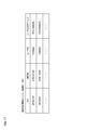
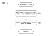
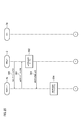
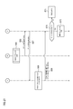
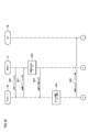
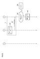
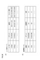
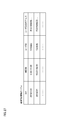
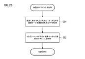
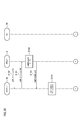
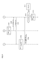
- FIG. 1 It is a figure which shows the gate opening system which concerns on this embodiment. It is a figure which shows an example of the hardware composition of a mobile terminal. It is a figure which shows an example of the hardware configuration of the management server. It is a figure which shows an example of the hardware configuration of a gate. It is a sequence diagram (the 1) for demonstrating the gate opening method which concerns on this Embodiment. It is a sequence diagram (the 2) for demonstrating the gate opening method which concerns on this Embodiment. (A) is a diagram showing an example of a user management table. (B) is a diagram showing an example of a ticket management table. It is a flowchart for demonstrating the process of acquiring the IP address of a gate.
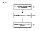
- FIG. 6 is a flowchart illustrating a process alternative to the process A shown in FIG. It is a sequence diagram (the 1) for demonstrating the gate opening method which concerns on a modification. It is a sequence diagram (No. 2) for explaining the gate opening method which concerns on a modification. It is a figure which shows the door lock release system of the vehicle which concerns on this embodiment. It is a figure which shows an example of the hardware composition of a vehicle. It is a sequence diagram (the 1) for demonstrating the door lock release method of the vehicle which concerns on this Embodiment. It is a sequence diagram (the 2) for demonstrating the door lock release method of the vehicle which concerns on this embodiment. (A) is a diagram showing an example of a user management table.
- (B) is a diagram showing an example of a vehicle management table. It is a figure which shows an example of the vehicle reservation management table. It is a flowchart for demonstrating the process of acquiring the IP address of a vehicle. It is a flowchart for demonstrating an alternative process of process B shown in FIG. It is a sequence diagram (the 1) for demonstrating the door lock release method of the vehicle which concerns on a modification. It is a sequence diagram (No. 2) for explaining the door lock release method of the vehicle which concerns on a modification. It is a figure which shows the door lock release system of the room which concerns on this embodiment. It is a figure which shows an example of the hardware composition of a door lock control system.
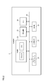
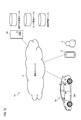
- the gate opening system 1 includes a mobile terminal 2 associated with the user U, a gate 3, and a management server 4.
- the mobile terminal 2, the gate 3, and the management server 4 are wirelessly or wiredly connected to the communication network 5.
- the communication network 5 is an IP network and includes at least one of a local area network (LAN), a wide area network (WAN), a radio access network (RAN), and the Internet.
- the mobile terminal 2 may be connected to the communication network 5 via an access point such as a wireless LAN router or a wireless base station.
- the gate 3 and the management server 4 may be connected to the router through a wired cable.
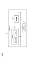
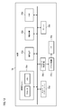
- FIG. 2 is a diagram showing an example of the hardware configuration of the mobile terminal 2.
- the mobile terminal 2 is a communication device carried by the user U, and is typically a smartphone. Further, the mobile terminal 2 may be a laptop computer, a tablet, or a wearable device (for example, a smart watch, an AR glass, etc.) worn on the user's body (for example, an arm, a head, etc.).
- the mobile terminal 2 includes a control unit 20, a storage device 23, a camera 24, a network interface 25, an input operation unit 27, and a display unit 26. These are directly or indirectly connected to each other via the bus 29.
- the control unit 20 is configured to control the operation of the mobile terminal 2, and includes a memory and a processor.
- the memory is configured to store computer-readable instructions.
- the memory may be composed of a ROM (Read Only Memory) in which various programs and the like are stored, a RAM (Random Access Memory) having a plurality of work areas in which various programs and the like executed by the processor are stored, and the like.
- the processor includes, for example, at least one of a CPU, an MPU (Micro Processing Unit), and a GPU (Graphics Processing Unit).
- the CPU may be composed of a plurality of CPU cores.
- the GPU may be composed of a plurality of GPU cores.
- the processor may be configured to develop a program designated from various programs incorporated in the storage device 23 or ROM on the RAM and execute various processes in cooperation with the RAM.
- the processor executes the program stored in the memory
- the mobile terminal 2 is configured to execute a part of the processing of the gate opening method according to the present embodiment.
- the storage device 23 is, for example, a storage device (storage) such as an HDD (Hard Disk Drive), an SSD (Solid State Drive), or a flash memory, and is configured to store programs and various data.
- a storage device such as an HDD (Hard Disk Drive), an SSD (Solid State Drive), or a flash memory, and is configured to store programs and various data.
- the network interface 25 is configured to connect the mobile terminal 2 to the communication network 5.
- the network interface 25 may include various wired connection terminals for communicating with an external device such as a server via the communication network 5.
- the network interface 25 may include various processing circuits and antennas for communicating with a wireless router or a wireless base station.
- Wireless communication standards include, for example, Wi-Fi (registered trademark), Bluetooth (registered trademark), ZigBee (registered trademark), LPWA, 5th generation mobile communication system (5G), and near field communication (NFC). Includes at least one.
- the input operation unit 27 is configured to accept the input operation of the user U who operates the mobile terminal 2 and to generate an instruction signal corresponding to the input operation.
- the input operation unit 27 is, for example, a touch panel arranged on the display unit 26, an operation button attached to the housing, a mouse and / or a keyboard, and the like. After the instruction signal generated by the input operation unit 27 is transmitted to the control unit 20 via the bus 29, the control unit 20 executes a predetermined operation according to the instruction signal.
- the display unit 26 may be a display device such as a liquid crystal display or an organic EL display.
- the display unit 26 and the input operation unit 27 may be connected to the mobile terminal 2 via an input / output interface such as a USB interface.
- the mobile terminal 2 has an IP address unique to the mobile terminal 2.
- the IP address of the mobile terminal 2 is significantly different from the conventional IP address in that it is not an IP address issued by an Internet service provider (ISP) but an IP address generated by the mobile terminal 2 itself.
- the IP address of the mobile terminal 2 is, for example, an IP address (128 bits) corresponding to IPv6 displayed in 32 hexadecimal digits.
- the IP address may be generated based on the public key of the mobile terminal 2 authenticated by the certificate authority.
- the control unit 20 generates the private key (512 bits) of the mobile terminal 2 and then generates the public key (256 bits) corresponding to the private key.
- the control unit 20 generates a hash value (256 bits) based on the public key and a predetermined hash function.
- the control unit 20 may determine the first 128 bits of the generated hash value (256 bits) as the IP address of the mobile terminal 2.
- the mobile terminal 2 acquires the digital certificate associated with the public key from the certificate authority.
- the public key of the mobile terminal 2 is authenticated by the certificate authority
- the IP address generated based on the public key is also indirectly authenticated by the certificate authority.
- the IP address of the mobile terminal 2 is significantly different from the conventional IP address in that it is an IP address unique to the mobile terminal 2 and is an IP address authenticated by a certificate authority.
- the gate opening method according to the present embodiment is significantly different from the conventional gate opening method in that the mobile terminal 2 is used as an admission ticket.
- the control unit 20 may check whether the IP address overlaps with the IP address of another device. Specifically, the mobile terminal 2 transmits information about the IP address of the mobile terminal 2 to the IP address management server that manages the IP address via the communication network.
- the IP address management server determines whether or not the IP address transmitted from the mobile terminal 2 matches one of a plurality of IP addresses included in the IP address management table stored in its own storage device.
- the IP address management server sends a message to the mobile terminal 2 to the effect that the registration of the IP address is rejected. You may send it.
- the mobile terminal 2 executes a series of processes for redetermining the IP address, and then transmits the information regarding the redetermined IP address to the IP address management server.
- the IP address management server sends a message to the effect that the registration of the IP address is permitted. May be sent to.
- FIG. 3 is a diagram showing an example of the hardware configuration of the management server 4.
- the management server 4 is composed of one or more servers.
- the management server 4 also functions as a WEB server.
- the management server 4 means one or more servers associated with the business operator that manages the ticket.
- the management server 4 includes a control unit 40, a storage device 43, and a network interface 45. These are directly or indirectly connected to each other via the bus 49.
- the control unit 40 is configured to control the operation of the management server 4, and includes a memory and a processor.
- the memory is configured to store computer-readable instructions.
- the memory may be composed of a ROM in which various programs and the like are stored and a RAM and the like having a plurality of work areas in which various programs and the like executed by the processor are stored.
- the processor includes, for example, at least one of a CPU, MPU and GPU.
- the CPU may be composed of a plurality of CPU cores.
- the GPU may be composed of a plurality of GPU cores.
- the processor may be configured to expand a program designated from various programs incorporated in the storage device 23 or ROM on the RAM and execute various processes in cooperation with the RAM.
- the management server 4 is configured to execute a part of the processing of the gate opening method according to the present embodiment.
- the storage device 43 is, for example, a storage device (storage) such as an HDD or SSD, and is configured to store programs and various data.
- the storage device 43 is configured to store a user management table and a ticket management table (see FIG. 7).
- the network interface 45 is configured to connect the management server 4 to the communication network 5.
- FIG. 4 is a diagram showing an example of the hardware configuration of the gate 3.
- the gate 3 may be an entrance gate configured to restrict entry into a predetermined space.
- the gate 3 may be installed at the entrance of a space where only those who have purchased a predetermined ticket are allowed to enter.
- the gate 3 may be installed at the entrance of a venue where a predetermined event (sports, music, amusement, etc.) is held.
- the gate 3 may be installed at the entrance of the facility where only the persons concerned can enter.
- the gate 3 may be installed at an entrance (for example, a ticket gate, a boarding gate, etc.) of a facility for using a predetermined public transportation system (for example, a railroad, an aircraft, a ship, etc.).
- a predetermined public transportation system for example, a railroad, an aircraft, a ship, etc.
- the gate 3 includes a control unit 30, a storage device 33, a network interface 35, a gate plate drive circuit 36, a gate plate 37, and a speaker 38. These components, except for the gate plate 37, are directly or indirectly connected to each other via the bus 39.
- the control unit 30 is configured to control the operation of the gate 3, and includes a memory and a processor.
- the memory is configured to store computer-readable instructions.
- the memory may be composed of a ROM in which various programs and the like are stored and a RAM and the like having a plurality of work areas in which various programs and the like executed by the processor are stored.
- the processor includes, for example, at least one of a CPU, MPU and GPU.
- the CPU may be composed of a plurality of CPU cores.
- the GPU may be composed of a plurality of GPU cores.
- the processor may be configured to expand a program designated from various programs incorporated in the storage device 33 or the ROM on the RAM and execute various processes in cooperation with the RAM.
- the gate 3 is configured to execute a part of the processing of the gate opening method according to the present embodiment.
- the storage device 33 is, for example, a storage device (storage) such as an HDD or SSD, and is configured to store programs and various data.
- the storage device 33 may be configured to store a ticket management table (see FIG. 7B).
- the network interface 35 is configured to connect the gate 3 to the communication network 5.
- the gate plate drive circuit 36 is configured to drive the gate plate 37 in response to an instruction signal from the control unit 30.
- the gate plate drive circuit 36 is configured to open / close the gate plate 37 in response to a gate opening signal / gate closing signal.
- the speaker 38 is configured to output a warning sound in response to an instruction signal from the control unit 30.
- the gate 3 has an IP address unique to the gate 3, similarly to the IP address of the mobile terminal 2. That is, the IP address of the gate 3 is not the IP address issued by the ISP, but the IP address generated by the gate 3 itself.
- the IP address of the gate 3 is, for example, an IP address (128 bits) corresponding to IPv6 displayed in 32 hexadecimal digits. Further, the IP address of the gate 3 may be generated based on the public key of the gate 3 authenticated by the certificate authority. Further, the public key of the gate 3 may be authenticated by a certificate authority. As described above, the IP address of the gate 3 is an IP address unique to the gate 3 and an IP address authenticated by the certificate authority.
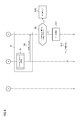
- the mobile terminal 2 transmits a request signal of a ticket purchase page for purchasing a predetermined ticket (for example, a concert ticket) to the management server 4 via the communication network 5.
- a predetermined ticket for example, a concert ticket
- the management server 4 also functions as a WEB server.
- the WEB browser of the mobile terminal 2 transmits the request signal to the management server 4 according to a communication protocol such as HTTP.
- the management server 4 transmits a ticket purchase page (WEB page) to the mobile terminal 2 via the communication network 5 in response to the request signal transmitted from the mobile terminal 2 (step S2).
- a login process for logging in to an online site (particularly, an online site for purchasing a ticket) provided by the management server 4 (WEB server) may be executed.
- the mobile terminal 2 may send login information (user ID and password) for logging in to the online site provided by the management server 4 to the management server 4 before and after executing the process of step S1.
- the management server 4 can authenticate the user U based on the transmitted login information. Further, the management server 4 may authenticate the user U based on the IP address of the mobile terminal 2 instead of the login information.
- the management server 4 authenticates the user U based on the IP address of the mobile terminal 2 without login information. be able to.
- the management server 4 can specify user attribute information such as a user ID corresponding to the IP address of the mobile terminal 2 by referring to the user management table (see FIG. 7A).
- step S3 the user U inputs the ticket purchase information for purchasing a predetermined ticket to the mobile terminal 2 through the input operation unit 27 of the mobile terminal 2.
- the user U may input seat information regarding the seat type and seat number of the concert hall and / or information regarding the credit card (credit information).
- the mobile terminal 2 executes the ticket purchase process. If the credit information of the user U is already registered in the user management table, the user U does not have to input the credit information.
- step S4 the mobile terminal 2 transmits the ticket purchase information input to the mobile terminal 2 to the management server 4.
- the management server 4 updates the ticket management table shown in FIG. 7B based on the ticket purchase information transmitted from the mobile terminal 2 (step S5).
- the management server 4 generates the ticket ID of the ticket purchased by the user U, and then generates the generated ticket ID, the seat information, the user ID of the user U, and the IP address of the mobile terminal 2. Register in the ticket management table.
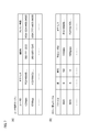
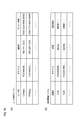
- the user management table and ticket management table shown in FIG. 7 are examples of management tables.
- the user management table and the ticket management table are stored in the storage device 43 (see FIG. 3) of the management server 4.
- the user management table includes a plurality of user ID information (user identification information) for a plurality of users, IP address information indicating a plurality of IP addresses unique to a plurality of mobile terminals, and a plurality of user attribute information (contact information and credit information). Etc.) including.
- the user ID, the IP address, and the user attribute information are associated with each other.
- each of the plurality of user ID information is associated with one of the plurality of IP address information and one of the plurality of user attribute information.
- the ticket management table includes a plurality of user ID information, a plurality of IP address information, a plurality of ticket ID information, and a plurality of seat information.
- the user ID, the IP address, the ticket ID, and the seat information are associated with each other.
- each of the plurality of user ID information is associated with one of the plurality of IP address information and one of the plurality of ticket ID information.
- the user management table and the ticket management table shown in FIG. 7 are merely examples.
- the ticket management table does not have to include IP address information.
- the user attribute information is not limited to contact information and credit information.
- the management server 4 may transmit the information regarding the ticket purchase price and the credit information of the user U to the external server that executes the payment related to the ticket purchase. In this way, the payment process related to the ticket purchase can be executed by the external server.
- step S6 the management server 4 transmits the ticket management table to the gate 3 via the communication network 5.
- the management server 4 may transmit the ticket management table to the gate 3 after the predetermined ticket is sold out or the ticket sale period has elapsed.
- the ticket management table may be stored in the storage device 33 of the gate 3.
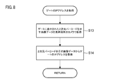
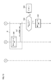
- the mobile terminal 2 acquires the IP address of the gate 3. Specifically, as shown in FIG. 8, in step S13, the user U uses the camera 24 of the mobile terminal 2 to use the two-dimensional barcode (for example, QR code (registered trademark)) displayed on the gate 3. To take an image. After that, the control unit 20 of the mobile terminal 2 acquires image data indicating the two-dimensional barcode acquired by the camera 24. Next, in step S14, the control unit 20 acquires information (128 bits) regarding the IP address of the gate 3 included in the two-dimensional pattern by analyzing the image data indicating the two-dimensional pattern.
- the two-dimensional barcode for example, QR code (registered trademark)
- the mobile terminal 2 transmits a gate opening signal requesting the opening of the gate 3 to the gate 3 via the communication network 5. Specifically, the mobile terminal 2 transmits the gate opening signal to the gate 3 by using the IP address of the mobile terminal 2 as the source address and the IP address of the gate 3 as the destination address. In this way, the gate 3 can specify the IP address of the mobile terminal 2 by referring to the source address of the gate opening signal.
- the gate 3 determines whether or not to allow the user U to enter a predetermined space (for example, a concert hall) based on the ticket management table stored in the storage device 33 and the IP address of the mobile terminal 2. (Step S9). Specifically, the gate 3 determines whether or not the IP address of the mobile terminal 2 matches one of the plurality of IP addresses included in the ticket management table. Here, when the IP address of the mobile terminal 2 matches one of the plurality of IP addresses included in the ticket management table, the gate 3 determines that the user U is allowed to enter the predetermined space (step S9). YES). On the other hand, if the IP address of the mobile terminal 2 does not match one of the plurality of IP addresses included in the ticket management table, the gate 3 determines that the user U is not allowed to enter the predetermined space (step S9). NO).
- step S9 If the determination result in step S9 is YES, the control unit 30 of the gate 3 transmits a gate opening signal to the gate plate drive circuit 36.
- the gate plate drive circuit 36 controls to open the gate plate 37 in response to the gate opening signal (step S11). In this way, the gate 3 is controlled so that the user U can enter the predetermined space.
- the gate 3 outputs a warning sound from the speaker 38 (step S10).
- step S12 the gate 3 specifies the seat information corresponding to the IP address of the mobile terminal 2 by referring to the ticket management table. After that, the gate 3 transmits the seat information as the ticket information to the mobile terminal 2. After that, the ticket information can be displayed on the display unit 26 of the mobile terminal 2. The gate 3 may output a receipt on which ticket information is printed. In this way, the user U can acquire the ticket information when passing through the gate 3, so that the convenience of the user U is improved.
- the mobile terminal 2 it is determined whether or not the user U associated with the mobile terminal 2 should be allowed to enter the predetermined space by using the IP address unique to the mobile terminal 2. Therefore, the mobile terminal 2 itself can be used as an admission ticket used when entering a predetermined space. Therefore, the user U does not need to bring a physical admission ticket or a two-dimensional barcode, and can pass through the gate 3 only by the mobile terminal 2.
- the user U does not prepare a physical ticket, a two-dimensional bar code, or the like corresponding to each gate when passing through the plurality of gates, and the user U does not prepare a plurality of gates. Can pass through. Therefore, it is possible to improve the convenience of the user U and provide the gate opening method and the gate opening system 1 capable of providing the user U with a new gate entrance experience. Further, according to the present embodiment, since the ticket management table is stored in the gate 3, it is determined whether or not the user U should be allowed to enter the predetermined space without the intervention of the management server 4.
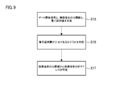
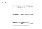
- FIG. 9 is a flowchart for explaining a process that is an alternative to the process A shown in FIG.
- step S15 the mobile terminal 2 receives a gate opening signal, a public key of the mobile terminal 2, and an electronic certificate associated with the public key of the mobile terminal 2 through short-range wireless communication (NFC).
- NFC short-range wireless communication
- the gate opening signal, the public key, and the digital certificate are transmitted from the mobile terminal 2 to the gate 3.
- the gate 3 determines whether or not the received digital certificate is valid (step S16). In particular, the gate 3 confirms the owner information, the issuer information, and the digital signature (hash value) of the digital certificate. Next, the gate 3 confirms the expiration date of the digital certificate. After that, the gate 3 determines the authenticity of the issuer of the digital certificate.
- the issuer of the digital certificate may be an intermediate certificate authority.
- the gate 3 identifies the IP address of the mobile terminal 2 from the public key of the mobile terminal 2 after determining that the digital certificate is valid (step S17). Specifically, the gate 3 generates a hash value based on the public key (256 bits) of the mobile terminal 2 and a predetermined hash function, and then obtains the IP address of the mobile terminal 2 from the generated hash value. Identify. In this respect, when the hash value is 256 bits, the first 128 bits of the hash value are determined as the IP address of the mobile terminal 2. In this way, since the gate 3 can specify the IP address of the mobile terminal 2, the gate 3 can enter the predetermined space of the user U based on the IP address of the specified mobile terminal 2 and the ticket management table. It is possible to determine whether or not to allow admission.
- FIGS. 10 and 11 are sequence diagrams for explaining a gate opening method according to a modified example.
- the gate opening method according to the modified example is different from the gate opening method according to the present embodiment in that the management server 4 executes a determination process of whether or not to allow the user U to enter a predetermined space.
- the same processing as the processing of the gate opening method of the present embodiment will not be repeatedly described.
- steps S20 to S24 are the same as the processes of steps S1 to S5 shown in FIG. 5, and therefore no particular description will be given.
- the management server 4 transmits the ticket management table to the gate 3. doing.
- the management server 4 does not transmit the ticket management table to the gate 3.
- step S25 the mobile terminal 2 acquires the IP address of the gate 3. After that, the mobile terminal 2 transmits the gate opening signal to the gate 3 via the communication network 5 by using the IP address of the mobile terminal 2 as the source address and the IP address of the gate 3 as the destination address.
- Step S26 the process of step S25 is the same as the process of step S7 shown in FIG. Further, each process shown in FIG. 9 may be applied instead of the processes of steps S25 and S26.
- the gate 3 transfers the gate opening signal and the information indicating the IP address of the mobile terminal 2 to the management server 4 via the communication network 5 (step S27).
- the management server 4 determines whether or not to allow the user U to enter a predetermined space (for example, a concert hall) based on the ticket management table stored in the storage device 43 and the IP address of the mobile terminal 2. (Step S28). Specifically, the management server 4 determines whether or not the IP address of the mobile terminal 2 matches one of the plurality of IP addresses included in the ticket management table.
- the management server 4 determines that the user U is allowed to enter the predetermined space.
- the gate opening permission signal and ticket information are transmitted to the gate 3 via the communication network 5 (step S29).
- the management server 4 determines that the user U is not allowed to enter the predetermined space.
- a gate opening disapproval signal is transmitted to the gate 3 via the communication network 5 (step S29).
- the gate 3 opens the gate plate 37 so that the user U can enter a predetermined space when the signal transmitted from the management server 4 is a gate opening permission signal (YES in step S30). S32).
- the gate 3 outputs a warning sound from the speaker 38 (step S31).
- step S33 the gate 3 transmits the ticket information transmitted from the management server 4 to the mobile terminal 2. After that, the ticket information can be displayed on the display unit 26 of the mobile terminal 2.
- the gate opening method according to the modified example it is determined whether or not the user U associated with the mobile terminal 2 should be allowed to enter the predetermined space by using the IP address unique to the mobile terminal 2. Will be done. Therefore, the mobile terminal 2 itself can be used as an admission ticket used when entering a predetermined space. Therefore, the user U does not need to bring a physical admission ticket or a two-dimensional barcode, and can pass through the gate 3 only by the mobile terminal 2. Further, in the gate opening method according to the modified example, it is not necessary to store the ticket management table in the gate 3, and it is not necessary for the gate 3 to execute the admission determination process.
- the management server 4 refers to both the user management table and the ticket management table to enter the entrance defined in step S28.
- the permission determination process may be executed. In this case, first, the management server 4 identifies the user ID of the user U corresponding to the IP address of the mobile terminal 2 based on the IP address of the mobile terminal 2 and the user management table. After that, the management server 4 may determine whether or not the user ID matches one of the plurality of user IDs included in the ticket management table based on the specified user ID and the ticket management table.
- the door unlocking system 1a includes a mobile terminal 2 associated with the user U, a vehicle 3a, and a management server 4a.
- the mobile terminal 2, the vehicle 3a, and the management server 4a are wirelessly or wiredly connected to the communication network 5.
- the mobile terminal 2 and the vehicle 3a may be connected to the communication network 5 via an access point such as a wireless LAN router or a wireless base station.
- the management server 4a may be connected to the router via a wired cable.
- FIG. 13 is a diagram showing an example of the hardware configuration of the vehicle 3a.
- the vehicle 3a is a connected vehicle connected to the communication network 5.
- the vehicle 3a may be, for example, a vehicle used for providing a car sharing service or a rental car service. Further, the vehicle 3a is not limited to a general vehicle, and may be an industrial vehicle. Further, the vehicle 3a is not limited to the four-wheeled vehicle, and may be a two-wheeled vehicle or a three-wheeled vehicle.
- the vehicle 3a includes a control unit 30a, a storage device 33a, a drive mechanism 32a, an HMI (Human Machine Interface) 34a, and a network interface 35a.
- the vehicle 3a further includes a door lock control circuit 36a, a door lock mechanism 37a, a door 39a, and a speaker 38a. These components of the vehicle 3a are directly or indirectly connected to each other via a bus based on the CAN or Ethernet® standard.
- the control unit 30a is composed of, for example, at least one electronic control unit (ECU).
- the control unit 30a includes a computer system including one or more processors and one or more memories.
- the memory is configured to store computer-readable instructions.
- the memory may consist of ROM and RAM.
- the processor includes, for example, at least one of a CPU, MPU and GPU.
- the CPU may be composed of a plurality of CPU cores.
- the GPU may be composed of a plurality of GPU cores.
- the processor may be configured to develop a program designated from various programs incorporated in the storage device 33a or ROM on the RAM and execute various processes in cooperation with the RAM.
- the vehicle 3a is configured to execute a part of the processing of the vehicle door unlocking method according to the present embodiment.
- the storage device 33a is, for example, a storage device (storage) such as an HDD or SSD, and is configured to store programs and various data. In particular, the storage device 33a may be configured to store the vehicle reservation management table (see FIG. 17).
- the drive mechanism 32a includes an accelerator device, a brake device, and a steering device.
- the HMI 34a includes a steering wheel, an accelerator pedal, and a brake pedal. Further, the HMI 34a may include a display unit that displays information about the vehicle 3a.
- the network interface 35a is configured to connect the vehicle 3a to the communication network 5.
- the network interface 35a is configured to connect the vehicle 3a to the communication network 5.
- the network interface 35a may include various processing circuits, antennas, and the like for communicating with a wireless router or a wireless base station.
- Wireless communication standards include, for example, at least one of Wi-Fi, Bluetooth, ZigBee, LPWA, 5th Generation Mobile Communication Systems (5G) and NFC.
- the door lock control circuit 36a is configured to control the door lock mechanism 37a in response to an instruction signal from the control unit 30a.
- the door lock mechanism 37a is provided on the door 39a and is configured to lock or unlock the door 39a.
- the door lock control circuit 36a locks or locks the door 39a by driving the door lock mechanism 37a provided on the door 39a in response to the door lock signal / door lock release signal transmitted from the control unit 30a. It is configured to be released.
- the management server 4a has the same configuration as the management server 4 shown in FIG. In this respect, the storage device of the management server 4a stores the user management table, the vehicle management table (see FIG. 16), and the vehicle reservation management table (see FIG. 17). In the present embodiment, the management server 4a also functions as a WEB server.
- the management server 4a means one or more servers associated with a business operator that manages vehicle usage reservations.
- the vehicle 3a has an IP address unique to the vehicle 3a, similarly to the IP address of the mobile terminal 2. That is, the IP address of the vehicle 3a is not the IP address issued by the ISP, but the IP address generated by the vehicle 3a itself.
- the IP address of the vehicle 3a is, for example, an IP address (128 bits) corresponding to IPv6 displayed in 32 hexadecimal digits. Further, the IP address of the vehicle 3a may be generated based on the public key of the vehicle 3a authenticated by the certificate authority. Further, the public key of the vehicle 3a may be authenticated by a certificate authority. As described above, the IP address of the vehicle 3a is an IP address unique to the vehicle 3a and an IP address authenticated by the certification authority.
- FIGS. 14 and 15 are sequence diagrams for explaining a method of unlocking the door of the vehicle 3a.
- the mobile terminal 2 transmits a request signal requesting a vehicle reservation page for reserving the use of the vehicle 3a to the management server 4a via the communication network 5 (step S40).
- the management server 4a also functions as a WEB server.
- the WEB browser of the mobile terminal 2 transmits the request signal to the management server 4a according to a communication protocol such as HTTP.
- the management server 4a transmits a vehicle reservation page (WEB page) to the mobile terminal 2 via the communication network 5 in response to the request signal transmitted from the mobile terminal 2 (step S41).
- a login process for logging in to an online site particularly, an online site for vehicle use reservation
- WEB server may be executed.
- step S42 the user U inputs the vehicle reservation information for making a reservation for using the vehicle 3a into the mobile terminal 2 through the input operation unit 27 of the mobile terminal 2.
- the vehicle reservation information includes, for example, information for identifying the vehicle 3a which is a reserved vehicle and information regarding the date and time of use of the vehicle 3a. In this way, the mobile terminal 2 executes the vehicle reservation process.
- step S43 the mobile terminal 2 transmits the vehicle reservation information input to the mobile terminal 2 to the management server 4a.
- the management server 4a updates the vehicle reservation management table (see FIG. 17) associated with the vehicle 3a based on the vehicle reservation information transmitted from the mobile terminal 2, the user management table, and the vehicle management table.
- Step S44 the management server 4a identifies the vehicle ID corresponding to the vehicle 3a based on the information for identifying the vehicle 3a included in the vehicle reservation information and the vehicle management table.
- the management server 4a reads the vehicle reservation table associated with the vehicle ID of the vehicle 3a.
- the management server 4a refers to the information on the usage date and time of the vehicle 3a and the information on the user U (user ID, IP address of the mobile terminal 2, etc.) included in the vehicle reservation information, and sets the vehicle reservation management table on the vehicle 3a. Update.
- the user management table, vehicle management table (see FIG. 16), and vehicle reservation management table (see FIG. 17) are examples of management tables. These management tables are stored in the storage device of the management server 4a.
- the user management table includes a plurality of user ID information (user identification information) indicating the IDs of a plurality of users, IP address information indicating a plurality of IP addresses unique to a plurality of mobile terminals, and a plurality of user attribute information (contact information). And credit information, etc.).
- the vehicle management table includes vehicle ID information indicating the IDs of a plurality of vehicles, IP address information indicating the IP addresses of a plurality of vehicles, and a plurality of vehicle attribute information (vehicle type, storage location, etc.).
- the user ID, the IP address, and the user attribute information are associated with each other.
- each of the plurality of user ID information is associated with one of the plurality of IP address information and one of the plurality of user attribute information.
- the vehicle ID, the IP address, and the vehicle attribute information are associated with each other.
- the vehicle reservation management table includes information on the vehicle usage date and usage time zone, user ID information, and IP address information corresponding to the user ID. In the vehicle reservation management table, this information is associated with each other. For example, the user ID of the user U, the IP address of the mobile terminal 2 associated with the user U, and the information regarding the usage date and the usage time zone in which the user U uses the vehicle 3a are registered in the vehicle reservation management table.
- step S45 the management server 4a transmits the vehicle reservation management table to the vehicle 3a via the communication network 5.
- the vehicle reservation management table is stored in the storage device 33a of the vehicle 3a.
- the management server 4a transmits information on the usage date and usage time zone of the vehicle 3a and information on the user U (user ID, IP address of the mobile terminal 2, etc.) to the vehicle 3a instead of the vehicle reservation management table. May be good.
- the vehicle 3a may update the vehicle reservation management table stored in the storage device 33a based on the information transmitted from the management server 4a.
- step S46 it is assumed that the user U exists in the vicinity of the vehicle 3a.
- step S46 the mobile terminal 2 acquires the IP address of the vehicle 3a.
- the user U captures a two-dimensional barcode (for example, a QR code or the like) displayed on the vehicle 3a using the camera 24 of the mobile terminal 2.
- the control unit 20 of the mobile terminal 2 acquires image data indicating the two-dimensional barcode acquired by the camera 24.
- step S52 the control unit 20 acquires information (128 bits) regarding the IP address of the vehicle 3a included in the two-dimensional pattern by analyzing the image data indicating the two-dimensional pattern.
- the mobile terminal 2 transmits a door unlock signal requesting the unlocking of the door 39a of the vehicle 3a to the vehicle 3a via the communication network 5. Specifically, the mobile terminal 2 transmits the door unlock signal to the vehicle 3a by using the IP address of the mobile terminal 2 as the source address and the IP address of the vehicle 3a as the destination address. In this way, the vehicle 3a can specify the IP address of the mobile terminal 2 by referring to the source address of the door lock release signal.
- the vehicle 3a determines whether to allow unlocking of the door 39a based on the vehicle reservation management table stored in the storage device 33a, the IP address of the mobile terminal 2, and the information regarding the current date and time. (Step S48). Specifically, the vehicle 3a determines whether or not the IP address corresponding to the user ID that reserved the vehicle 3a in the reserved time zone including the current date and time matches the IP address of the mobile terminal 2. Here, if the two IP addresses match each other, the vehicle 3a determines that the unlocking of the door 39a is permitted (YES in step S48). On the other hand, if the two IP addresses do not match each other, the vehicle 3a determines that unlocking of the door 39a is not permitted (NO in step S48).
- step S48 If the determination result in step S48 is YES, the control unit 30a of the vehicle 3a transmits the door lock release signal to the door lock control circuit 36a.
- the door lock control circuit 36a unlocks the door 39a by driving the door lock mechanism 37a in response to the door lock release signal. In this way, the door lock of the vehicle 3a is released (step S50).
- the vehicle 3a outputs a warning sound from the speaker 38a (step S49).
- the door unlocking method of the vehicle 3a it is determined whether or not the unlocking of the door 39a of the vehicle 3a is permitted by using the IP address of the mobile terminal 2. Therefore, the mobile terminal 2 itself can be used as a key for unlocking the door 39a of the vehicle 3a. Therefore, the user U does not need to bring a physical key (card key or the like), and can unlock the door 39a only by the mobile terminal 2. Further, when using a plurality of vehicles, the user U can unlock the doors of the plurality of vehicles without preparing a physical key corresponding to each vehicle. Therefore, it is possible to improve the convenience of the user U and provide the user U with a door unlocking method capable of providing a new car sharing experience or a car rental experience.
- the mobile terminal 2 and the vehicle 3a know each other's IP addresses after the process of step S50, communication between the mobile terminal 2 and the vehicle 3a is established. In this way, the mobile terminal 2 is communicably connected to the vehicle 3a via the communication network 5. Therefore, the mobile terminal 2 can lock the door 39a by transmitting a door lock signal requesting the lock of the door 39a of the vehicle 3a to the vehicle 3a. On the other hand, the mobile terminal 2 can unlock the door 39a by transmitting a door unlock signal requesting the unlocking of the door 39a of the vehicle 3a to the vehicle 3a. Further, through the establishment of communication between the mobile terminal 2 and the vehicle 3a, the user U can control the drive of the vehicle 3a using the mobile terminal 2. For example, the user U can activate the vehicle 3a using the mobile terminal 2. In addition, the user U can end the activation of the vehicle 3a by using the mobile terminal 2.
- FIG. 19 is a flowchart for explaining a process that is an alternative to the process B shown in FIG.
- the mobile terminal 2 uses short-range wireless communication (NFC) to release the door lock signal, the public key of the mobile terminal 2, and the electronic associated with the public key of the mobile terminal 2.
- NFC short-range wireless communication
- Send the certificate to the vehicle 3a For example, when the user U does not connect the mobile terminal 2 to the NFC interface (a part of the network interface 35a) of the vehicle 3a, the door unlock signal, the public key, and the electronic certificate are transmitted from the mobile terminal 2 to the vehicle 3a.
- the vehicle 3a determines whether or not the received digital certificate is valid (step S54). In particular, the vehicle 3a confirms the owner information, the issuer information, and the digital signature (hash value) of the digital certificate. Next, the vehicle 3a confirms the expiration date of the digital certificate. After that, the vehicle 3a determines the reliability of the issuer of the digital certificate.
- the issuer of the digital certificate may be an intermediate certificate authority.
- the vehicle 3a identifies the IP address of the mobile terminal 2 from the public key of the mobile terminal 2 after determining that the electronic certificate is valid (step S55). Specifically, the vehicle 3a generates a hash value based on the public key (256 bits) of the mobile terminal 2 and a predetermined hash function, and then obtains the IP address of the mobile terminal 2 from the generated hash value. Identify. In this respect, when the hash value is 256 bits, the first 128 bits of the hash value are determined as the IP address of the mobile terminal 2. In this way, since the vehicle 3a can specify the IP address of the mobile terminal 2, the door lock of the vehicle 3a is released based on the IP address of the specified mobile terminal 2 and the vehicle reservation management table. Can be determined whether or not to allow.
- FIGS. 20 and 21 are sequence diagrams for explaining a method of unlocking the door of the vehicle 3a according to the modified example.
- the door lock release method according to the modified example is different from the door lock release method according to the present embodiment in that the management server 4a executes a determination process for determining whether to release the door lock of the vehicle 3a.
- the same process as the process of the door lock release method of the present embodiment will not be described again.
- the processes of steps S60 to S64 are the same as the processes of steps S40 to S44 shown in FIG. 14, and therefore no particular description will be given.
- the management server 4a transmits the vehicle reservation management table associated with the vehicle 3a to the vehicle 3a.
- the management server 4a does not transmit the vehicle reservation management table to the vehicle 3a.
- step S65 the mobile terminal 2 acquires the IP address of the vehicle 3a. After that, the mobile terminal 2 transmits the door lock release signal to the vehicle 3a via the communication network 5 by using the IP address of the mobile terminal 2 as the source address and the IP address of the vehicle 3a as the destination address.
- Step S66 the process of step S65 is the same as the process of step S46 shown in FIG. Further, each process shown in FIG. 19 may be applied instead of the processes of steps S46 and S47.
- the vehicle 3a transfers the door lock release signal and the information indicating the IP address of the mobile terminal 2 to the management server 4a via the communication network 5 (step S67).
- the management server 4a identifies the vehicle ID of the vehicle 3a based on the IP address of the vehicle 3a, which is the destination address, and the vehicle management table.
- the management server 4a reads out the vehicle reservation management table of the vehicle 3a based on the vehicle ID of the vehicle 3a.
- the management server 4a determines whether to allow the unlocking of the door 39a based on the vehicle reservation management table of the vehicle 3a stored in the storage device, the IP address of the mobile terminal 2, and the information regarding the current date and time. Determine (step S68).
- the management server 4a determines whether or not the IP address corresponding to the user ID that reserved the vehicle 3a in the reserved time zone including the current date and time matches the IP address of the mobile terminal 2.
- the management server 4a determines that the unlocking of the door 39a is permitted, and then transmits the door unlocking permission signal to the vehicle 3a.
- the management server 4a determines that the unlocking of the door 39a is not permitted, and then transmits a door unlocking disapproval signal to the vehicle 3a (step S69).
- the control unit 30a of the vehicle 3a transmits the door lock release signal to the door lock control circuit 36a.
- the door lock control circuit 36a unlocks the door 39a by driving the door lock mechanism 37a in response to the door lock release signal. In this way, the door lock of the vehicle 3a is released (step S72).
- the signal transmitted from the management server 4a is a door lock release permission signal (NO in step S70)
- the vehicle 3a outputs a warning sound from the speaker 38a (step S71).
- the vehicle door unlocking method it is similarly determined whether or not to permit the unlocking of the door 39a of the vehicle 3a using the IP address of the mobile terminal 2. Therefore, the mobile terminal 2 itself can be used as a key for unlocking the door 39a of the vehicle 3a. Therefore, the user U does not need to bring a physical key (card key or the like), and can unlock the door 39a only by the mobile terminal 2. Further, when using a plurality of vehicles, the user U can unlock the doors of the plurality of vehicles without preparing a physical key corresponding to each vehicle. Therefore, it is possible to improve the convenience of the user U and provide the user U with a door unlocking method capable of providing a new car sharing experience or a car rental experience. Further, in the door lock release method according to the modified example, it is not necessary to store the vehicle reservation management table in the vehicle 3a, and it is not necessary to determine whether the vehicle 3a should release the door lock.
- the management server 4a refers to both the user management table and the vehicle reservation management table to lock the door as defined in step S68.
- the cancellation determination process may be executed.
- the management server 4a identifies the user ID of the user U corresponding to the IP address of the mobile terminal 2 based on the IP address of the mobile terminal 2 and the user management table.
- the management server 4a determines whether or not the user ID that reserved the vehicle 3a in the reserved time zone including the current date and time matches the specified user ID based on the specified user ID and the vehicle reservation management table. You may.
- the door unlocking system 1b includes a mobile terminal 2 associated with the user U, a room 3b, and a management server 4b.
- the mobile terminal 2, the room 3b, and the management server 4b are wirelessly or wiredly connected to the communication network 5.
- the mobile terminal 2 and the room 3b may be connected to the communication network 5 via an access point such as a wireless LAN router or a wireless base station.
- the management server 4b may be connected to the router via a wired cable.
- FIG. 23 is a diagram showing an example of the hardware configuration of the door lock control system 30b.
- the room 3b is a room of a predetermined facility, and the type of facility is not particularly limited.
- the room 3b according to the present embodiment is a hotel room, a private house room, or a conference room.
- Room 3b may be, for example, a room used to provide a room sharing service.
- Room 3b includes a door 32b and a door lock control system 30b configured to control locking or unlocking of the door 32b.
- the door lock control system 30b includes a control unit 31b, a storage device 33b, a network interface 35b, a door lock control circuit 36b, a door lock mechanism 37b, and a speaker 38b. These components of the door lock control system 40b are directly or indirectly connected to each other via a bus.
- the control unit 31b includes one or more processors and one or more memories.
- the memory is configured to store computer-readable instructions.
- the memory may consist of ROM and RAM.
- the processor includes, for example, at least one of a CPU, MPU and GPU.
- the CPU may be composed of a plurality of CPU cores.
- the GPU may be composed of a plurality of GPU cores.
- the processor may be configured to develop a program designated from various programs incorporated in the storage device 33b or ROM on the RAM and execute various processes in cooperation with the RAM.
- the door lock control system 30b is configured to execute a part of the processing of the door unlocking method of the room 3b according to the present embodiment. ..
- the storage device 33b is, for example, a storage device (storage) such as an HDD or SSD, and is configured to store programs and various data.
- the storage device 33b may be configured to store a room reservation management table (see FIG. 27).
- the network interface 35b is configured to connect the door lock control system 30b to the communication network 5.
- the network interface 35b is configured to connect the door lock control system 30b to the communication network 5.
- the network interface 35b may include various processing circuits and antennas for communicating with a wireless router or a wireless base station.
- Wireless communication standards include, for example, at least one of Wi-Fi, Bluetooth, ZigBee, LPWA, 5th Generation Mobile Communication Systems (5G) and NFC.
- the door lock control circuit 36b is configured to control the door lock mechanism 37b in response to an instruction signal from the control unit 31b.
- the door lock mechanism 37b is provided on the door 32b and is configured to lock or unlock the door 32b.
- the door lock control circuit 36b locks or locks the door 32b by driving the door lock mechanism 37b provided on the door 32b in response to the door lock signal / door lock release signal transmitted from the control unit 31b. It is configured to be released.
- the management server 4b has the same configuration as the management server 4 shown in FIG. In this respect, the storage device of the management server 4b stores the user management table, the room management table (see FIG. 26), and the room reservation management table (see FIG. 27). In the present embodiment, the management server 4b also functions as a WEB server.
- the management server 4b means one or more servers associated with a business operator that manages room usage reservations.
- the room 3b (door lock control system 30b) has an IP address unique to the room 3b (door lock control system 30b), similarly to the IP address of the mobile terminal 2. That is, the IP address of the room 3b is not the IP address issued by the ISP, but the IP address generated by the room 3b itself.
- the IP address of the room 3b is, for example, an IP address (128 bits) corresponding to IPv6 displayed in 32 hexadecimal digits. Further, the IP address of the room 3b may be generated based on the public key of the room 3b authenticated by the certificate authority. Further, the public key of room 3b may be authenticated by a certificate authority. As described above, the IP address of the room 3b is an IP address unique to the room 3b and an IP address authenticated by the certificate authority.
- FIGS. 24 and 25 are sequence diagrams for explaining a method of unlocking the door of the room 3b.
- the mobile terminal 2 transmits a request signal requesting a room reservation page for reserving the use of the room 3b to the management server 4b via the communication network 5 (step S80).
- the management server 4b also functions as a WEB server.
- the WEB browser of the mobile terminal 2 transmits the request signal to the management server 4b according to a communication protocol such as HTTP.
- the management server 4b transmits a room reservation page (WEB page) to the mobile terminal 2 via the communication network 5 in response to the request signal transmitted from the mobile terminal 2 (step S81).
- a login process for logging in to an online site (particularly, an online site for room use reservation) provided by the management server 4b (WEB server) may be executed.
- step S82 the user U inputs the room reservation information for making a reservation for using the room 3b to the mobile terminal 2 through the input operation unit 27 of the mobile terminal 2.
- the room reservation information includes, for example, information for identifying the room 3b, which is a reserved room, and information regarding the date and time of use of the room 3b. In this way, the mobile terminal 2 executes the room reservation process.
- step S83 the mobile terminal 2 transmits the room reservation information input to the mobile terminal 2 to the management server 4b.
- the management server 4b updates the room reservation management table (see FIG. 27) associated with the room 3b based on the room reservation information transmitted from the mobile terminal 2, the user management table, and the room management table.
- Step S84 the management server 4b specifies the room ID corresponding to the room 3b based on the information for specifying the room 3b included in the room reservation information and the room management table.
- the management server 4b reads out the room reservation table associated with the room ID of the room 3b.
- the management server 4b refers to the information on the usage date and usage time zone of the room 3b and the information on the user U (user ID and IP address of the mobile terminal 2 etc.) included in the room reservation information, and the room related to the room 3b. Update the reservation management table.
- the user management table, the room management table (see FIG. 26), and the room reservation management table (see FIG. 27) are examples of management tables. These management tables are stored in the storage device of the management server 4b.
- the user management table includes a plurality of user ID information (user identification information) indicating the IDs of a plurality of users, IP address information indicating a plurality of IP addresses unique to a plurality of mobile terminals, and a plurality of user attribute information (contact information). And credit information, etc.).
- the room management table includes room ID information indicating the IDs of a plurality of rooms, IP address information indicating the IP addresses of the plurality of rooms, and a plurality of room attribute information (room numbers, places, etc.).
- the user ID, the IP address, and the user attribute information are associated with each other.
- each of the plurality of user ID information is associated with one of the plurality of IP address information and one of the plurality of user attribute information.
- the room ID, the IP address, and the room attribute information are associated with each other.
- the room reservation management table includes information on the usage date and usage time zone of the room 3b, user ID information, and IP address information corresponding to the user ID. In the room reservation management table, this information is associated with each other. For example, the user ID of the user U, the IP address of the mobile terminal 2 associated with the user U, and the information regarding the usage date and the usage time zone in which the user U uses the room 3b are registered in the room reservation management table.
- the management server 4b transmits the room reservation management table to the room 3b (door lock control system 30b) via the communication network 5.
- the room reservation management table is stored in the storage device 33b of the door lock control system 30b.
- the management server 4b sends information about the usage date and time zone of the room 3b and information about the user U (user ID and IP address of the mobile terminal 2) to the door lock control system 30b. You may send it.
- the door lock control system 30b may update the room reservation management table stored in the storage device 33b based on the information transmitted from the management server 4b.
- step S86 the mobile terminal 2 acquires the IP address of the room 3b.
- the user U captures a two-dimensional barcode (for example, a QR code or the like) displayed on the door 32b using the camera 24 of the mobile terminal 2.
- the control unit 20 of the mobile terminal 2 acquires image data indicating the two-dimensional barcode acquired by the camera 24.
- step S92 the control unit 20 acquires information (128 bits) regarding the IP address of the room 3b included in the two-dimensional pattern by analyzing the image data indicating the two-dimensional pattern.
- step S87 the mobile terminal 2 transmits a door unlock signal requesting the unlock of the door 32b to the door lock control system 30b via the communication network 5. Specifically, the mobile terminal 2 transmits the door lock release signal to the door lock control system 30b by using the IP address of the mobile terminal 2 as the source address and the IP address of the room 3b as the destination address. To do. In this way, the door lock control system 30b can specify the IP address of the mobile terminal 2 by referring to the source address of the door lock release signal.
- step S88 whether or not the door lock control system 30b permits unlocking of the door 32b based on the room reservation management table stored in the storage device 33b, the IP address of the mobile terminal 2, and the information regarding the current date and time.
- the door lock control system 30b determines whether or not the IP address corresponding to the user ID that reserved the room 3b in the reserved time zone including the current date and time matches the IP address of the mobile terminal 2.
- the door lock control system 30b determines that the unlocking of the door 32b is permitted (YES in step S88).
- the door lock control system 30b determines that the unlocking of the door 32b is not permitted (NO in step S88).
- step S88 If the determination result in step S88 is YES, the control unit 31b of the door lock control system 30b transmits the door lock release signal to the door lock control circuit 36b.
- the door lock control circuit 36b unlocks the door 32b by driving the door lock mechanism 37b in response to the door lock release signal. In this way, the door lock of the room 3b is released (step S90).
- the door lock control system 30b outputs a warning sound from the speaker 38b (step S89).
- the door unlocking method of the room 3b it is determined whether or not the unlocking of the door 32b of the room 3b is permitted by using the IP address of the mobile terminal 2. Therefore, the mobile terminal 2 itself can be used as a key for unlocking the door 32b. Therefore, the user U does not need to bring a physical key (card key or the like), and can unlock the door 32b only by the mobile terminal 2. Further, when using a plurality of rooms, the user U can unlock the doors of the plurality of rooms without preparing a physical key corresponding to each room. Therefore, it is possible to improve the convenience of the user U and provide a door unlocking method capable of providing the user U with a new room sharing experience.
- the mobile terminal 2 and the door lock control system 30b know each other's IP addresses after the process of step S90, communication between the mobile terminal 2 and the door lock control system 30b is established. In this way, the mobile terminal 2 is communicably connected to the door lock control system 30b via the communication network 5. Therefore, the mobile terminal 2 can lock the door 32b by transmitting a door lock signal requesting the lock of the door 32b to the door lock control system 30b. On the other hand, the mobile terminal 2 can unlock the door 32b by transmitting a door unlock signal requesting the unlock of the door 32b to the door lock control system 30b.
- FIG. 29 is a flowchart for explaining a process that is an alternative to the process C shown in FIG. 25.
- step S93 the mobile terminal 2 receives a door unlock signal, a public key of the mobile terminal 2, and an electron associated with the public key of the mobile terminal 2 through short-range wireless communication (NFC).
- the certificate is sent to the door lock control system 30b.
- the door lock release signal, the public key, and the electronic certificate are transmitted from the mobile terminal 2 to the door lock control system. It is transmitted to 30b.
- the door lock control system 30b determines whether or not the received digital certificate is valid (step S94). In particular, the door lock control system 30b confirms the owner information, the issuer information, and the digital signature (hash value) of the digital certificate. Next, the door lock control system 30b confirms the expiration date of the digital certificate. After that, the door lock control system 30b determines the reliability of the issuer of the digital certificate.
- the issuer of the digital certificate may be an intermediate certificate authority.
- the door lock control system 30b identifies the IP address of the mobile terminal 2 from the public key of the mobile terminal 2 after determining that the electronic certificate is valid (step S95). Specifically, the door lock control system 30b generates a hash value based on the public key (256 bits) of the mobile terminal 2 and a predetermined hash function, and then uses the generated hash value of the mobile terminal 2 to generate a hash value. Identify the IP address. In this respect, when the hash value is 256 bits, the first 128 bits of the hash value are determined as the IP address of the mobile terminal 2. In this way, since the door lock control system 30b can specify the IP address of the mobile terminal 2, the door of the room 3b is based on the IP address of the specified mobile terminal 2 and the room reservation management table. It is possible to determine whether to allow unlocking.
- FIGS. 30 and 31 are sequence diagrams for explaining a method of unlocking the door of the room 3b according to the modified example.
- the door lock release method according to the modified example is different from the door lock release method according to the present embodiment in that the management server 4b executes the determination process of whether to release the door lock of the room 3b.
- the same process as the process of the door lock release method of the present embodiment will not be described again.
- steps S100 to S104 is the same as the processing of steps S80 to S84 shown in FIG. 24, and thus no particular description will be given.
- the management server 4b transmits the room reservation management table associated with the room 3b to the room 3b.
- the management server 4b does not transmit the room reservation management table to the room 3b.
- step S105 the mobile terminal 2 acquires the IP address of the room 3b. After that, the mobile terminal 2 uses the IP address of the mobile terminal 2 as the source address and the IP address of the room 3b as the destination address, so that the door lock release signal is transmitted to the door lock control system via the communication network 5. It is transmitted to 30b (step S106).
- step S105 the process of step S105 is the same as the process of step S86 shown in FIG. Further, each process shown in FIG. 29 may be applied instead of the processes of steps S105 and S106.
- the door lock control system 30b transfers the door lock release signal and the information indicating the IP address of the mobile terminal 2 to the management server 4b via the communication network 5 (step S107).
- the management server 4b identifies the room ID of the room 3b based on the IP address of the door lock control system 30b (room 3b) which is the destination address and the room management table.
- the management server 4b reads out the room reservation management table of the room 3b based on the room ID of the room 3b.
- the management server 4b determines whether to allow the unlocking of the door 32b based on the room reservation management table of the room 3b stored in the storage device, the IP address of the mobile terminal 2, and the information regarding the current date and time. Determine (step S108).
- the management server 4b determines whether or not the IP address corresponding to the user ID that reserved the room 3b in the reserved time zone including the current date and time matches the IP address of the mobile terminal 2.
- the management server 4b determines that the unlocking of the door 32b is permitted, and then transmits the door unlocking permission signal to the door lock control system 30b.
- the management server 4b determines that the unlocking of the door 32b is not permitted, and then transmits a door unlock disapproval signal to the door lock control system 30b (step). S109).
- the control unit 31b of the door lock control system 30b sends the door lock release signal to the door lock control circuit 36b. Send.
- the door lock control circuit 36b unlocks the door 32b by driving the door lock mechanism 37b in response to the door lock release signal. In this way, the door lock of the room 3b is released (step S112).
- the signal transmitted from the management server 4b is a door lock release disapproval signal (NO in step S110)
- the door lock control system 30b outputs a warning sound from the speaker 38b (step S111).
- the door unlocking method of the room 3b it is similarly determined whether or not the unlocking of the door 32b is permitted by using the IP address of the mobile terminal 2. Therefore, the mobile terminal 2 itself can be used as a key for unlocking the room 3b. Therefore, the user U does not need to bring a physical key (card key or the like), and can unlock the door 32b only by the mobile terminal 2. Further, when using a plurality of rooms, the user U can unlock the doors of the plurality of rooms without preparing a physical key corresponding to each room. Therefore, it is possible to improve the convenience of the user U and provide a door unlocking method capable of providing the user U with a new room sharing experience. Further, in the door lock release method according to the modified example, it is not necessary to store the room reservation management table in the room 3b, and it is not necessary to determine whether the room 3b should release the door lock.
- the management server 4b refers to both the user management table and the room reservation management table to lock the door as defined in step S108.
- the cancellation determination process may be executed.
- the management server 4b identifies the user ID of the user U corresponding to the IP address of the mobile terminal 2 based on the IP address of the mobile terminal 2 and the user management table.
- the management server 4b determines whether or not the user ID that reserved the room 3b in the reserved time zone including the current date and time matches the specified user ID based on the specified user ID and the room reservation management table. You may.
- the IP address which is a network address corresponding to the Internet protocol
- the network address is described as an example of the network addresses of the mobile terminal 2, the gate 3, the vehicle 3a, and the room 3b (door lock control system 30b). Is not limited to IP addresses.
- the network address may be a network address corresponding to a predetermined communication protocol other than the Internet protocol.
- the method according to the present embodiment may be realized by a computer program.
- the computer program may be stored in a storage device, a ROM, or the like.
- the computer program includes a magnetic disk (for example, HDD, floppy disk), an optical disk (for example, CD-ROM, DVD-ROM, Blu-ray (registered trademark) disk), a magneto-optical disk (for example, MO), and a flash.
- It may be stored in a computer-readable storage medium such as a memory (for example, SD card, USB memory, SSD).
- a computer program stored in a computer-readable storage medium may be incorporated in the storage device. Further, the program incorporated in the storage device may be loaded on the RAM, and then the processor may execute the program loaded on the RAM.
Landscapes
- Engineering & Computer Science (AREA)
- General Physics & Mathematics (AREA)
- Physics & Mathematics (AREA)
- Computer Networks & Wireless Communication (AREA)
- Signal Processing (AREA)
- General Health & Medical Sciences (AREA)
- Medical Informatics (AREA)
- Health & Medical Sciences (AREA)
- Computing Systems (AREA)
- Telephonic Communication Services (AREA)
- Telephone Function (AREA)
- Mobile Radio Communication Systems (AREA)
- Lock And Its Accessories (AREA)
- Selective Calling Equipment (AREA)
- Management, Administration, Business Operations System, And Electronic Commerce (AREA)
Abstract
Description
ユーザに関連付けられた携帯端末に固有のネットワークアドレスを用いて、所定の空間への入場を規制するように構成されたゲートに前記ゲートの開放を要求するゲート開放信号を送信するステップと、
前記ゲート開放信号の受信に応じて、管理テーブルと前記携帯端末のネットワークアドレスとに基づいて、前記ユーザの前記所定の空間への入場を許可するかどうかを判定するステップと、
前記ユーザの前記所定の空間への入場を許可するとの判定に応じて、前記ユーザが前記所定の空間に入場できるように前記ゲートを制御するステップと、を含む。
前記管理テーブルは、各々が複数のユーザの一つに関連付けられた複数の携帯端末に固有の複数のネットワークアドレスを示す複数のネットワークアドレス情報を含む。
また、本方法によれば、ユーザは、複数のゲートを通過する際に各ゲートに対応する物理的なチケットや2次元バーコード等を用意せずに、複数のゲートを通過することができる。
したがって、ユーザの利便性を向上させると共に、ユーザに新たなゲート入場体験を提供可能なゲート開放方法を提供することができる。
前記ユーザの前記所定の空間への入場を許可するかどうかを判定するステップは、
前記ユーザ管理テーブルと前記携帯端末のネットワークアドレスに基づいて、当該携帯端末のネットワークアドレスに対応するユーザ識別情報を特定するステップと、
前記特定されたユーザ識別情報と前記チケット管理テーブルに基づいて、前記特定されたユーザ識別情報が前記チケット管理テーブルに含まれる複数のユーザ識別情報の一つと一致するかどうかを判定するステップと、
前記特定されたユーザ識別情報が前記チケット管理テーブルに含まれる複数のユーザ識別情報の一つと一致する場合に、前記ユーザの前記所定の空間への入場を許可することを決定するステップと、を含んでもよい。
前記チケット管理テーブルは、前記複数のネットワークアドレス情報を含んでもよい。
前記ユーザの前記所定の空間への入場を許可するかどうかを判定するステップは、
前記チケット管理テーブルと前記携帯端末のネットワークアドレスとに基づいて、前記携帯端末のネットワークアドレスが前記チケット管理テーブルに含まれる前記複数の携帯端末のネットワークアドレスの一つと一致するかどうかを判定するステップと、
前記携帯端末のネットワークアドレスが前記チケット管理テーブルに含まれる前記複数の携帯端末のネットワークアドレスの一つと一致する場合に、前記ユーザの前記所定の空間への入場を許可することを決定するステップと、を含んでもよい。
前記ユーザの前記所定の空間への入場を許可するかどうかを判定するステップは、前記管理サーバにより実行され、前記通信ネットワークを介して前記ゲートから前記携帯端末のネットワークアドレスに関する情報を受信するステップを含んでもよい。
前記ユーザの前記所定の空間への入場を許可するかどうかを判定するステップは、前記ゲートにより実行されてもよい。
ユーザに関連付けられると共に、固有のネットワークアドレスを有する携帯端末と、
前記携帯端末に通信可能に接続されると共に、所定の空間への入場を規制するように構成されたゲートと、を備える。
前記ゲート開放システムは、前記ゲート開放方法を実行するように構成されている。
ユーザに関連付けられた携帯端末に固有のネットワークアドレスを用いて、対象物に前記対象物のドアのロック解除を要求するドアロック解除信号を送信するステップと、
前記ドアロック解除信号の受信に応じて、管理テーブルと前記携帯端末のネットワークアドレスとに基づいて、前記ドアのロック解除を許可するかどうかを判定するステップと、
前記ドアのロック解除を許可するとの判定に応じて、前記ドアをロック解除させるステップと、を含む。
前記管理テーブルは、各々が複数のユーザの一つに関連付けられた複数の携帯端末に固有の複数のネットワークアドレスを示す複数のネットワークアドレス情報を含む。
また、本方法によれば、ユーザは、複数の対象物を利用する際に各対象物に対応する物理的な鍵を用意せずに、複数の対象物のドアをロック解除することができる。
したがって、ユーザの利便性を向上させると共に、ユーザに新たな体験(例えば、シェアリング体験)を提供可能なドアロック解除方法を提供することができる。
前記ユーザ管理テーブルは、複数のユーザに関する複数のユーザ識別情報と、各々が前記複数のユーザ識別情報の一つに関連付けられた前記複数のネットワークアドレス情報とを含んでもよい。
前記予約管理テーブルは、複数のユーザ識別情報を含んでもよい。
前記ドアのロック解除を許可するかどうかを判定するステップは、
前記ユーザ管理テーブルと前記携帯端末のネットワークアドレスに基づいて、前記携帯端末のネットワークアドレスに対応するユーザ識別情報を特定するステップと、
前記特定されたユーザ識別情報と前記予約管理テーブルに基づいて、前記対象物が前記ユーザ識別情報に対応する前記ユーザによって予約されているかどうかを判定するステップと、
前記対象物が前記ユーザ識別情報に対応する前記ユーザによって予約されている場合に、前記ドアのロック解除を許可することを決定するステップと、を含んでもよい。
前記予約管理テーブルは、前記複数のネットワークアドレス情報を含んでもよい。
前記ドアのロック解除を許可するかどうかを判定するステップは、
前記予約管理テーブルと前記携帯端末のネットワークアドレスとに基づいて、前記対象物が前記携帯端末に関連付けられた前記ユーザによって予約されているかどうかを判定するステップと、
前記対象物が前記携帯端末に関連付けられた前記ユーザによって予約されている場合に前記ドアのロック解除を許可することを決定するステップと、を含んでもよい。
前記ドアのロック解除を許可するかどうかを判定するステップは、前記管理サーバにより実行され、前記通信ネットワークを介して前記対象物から前記携帯端末のネットワークアドレスに関する情報を受信するステップを含んでもよい。
前記ドアのロック解除を許可するかどうかを判定するステップは、前記対象物によって実行されてもよい。
また、本方法によれば、ユーザは、複数の車両を利用する際に各車両に対応する物理的な鍵を用意せずに、複数の車両のドアをロック解除することができる。
したがって、ユーザの利便性を向上させると共に、ユーザに新たなカーシェアリング体験又はカーレンタル体験を提供可能なドアロック解除方法を提供することができる。
また、本方法によれば、ユーザは、複数の部屋を利用する際に各部屋に対応する物理的な鍵を用意せずに、複数の部屋のドアをロック解除することができる。
したがって、ユーザの利便性を向上させると共に、新たなルームシェアリング体験を提供可能なドアロック解除方法を提供することができる。
前記ドアロック解除は、前記ドアロック解除方法を実行するように構成されている。
以下、本発明の実施形態(以下、本実施形態という。)に係るゲート開放システム1について図面を参照しながら説明する。最初に、図1を参照してゲート開放システム1について説明する。図1に示すように、ゲート開放システム1は、ユーザUに関連付けられた携帯端末2と、ゲート3と、管理サーバ4とを備える。携帯端末2と、ゲート3と、管理サーバ4は、通信ネットワーク5に無線又は有線により通信可能に接続されている。通信ネットワーク5は、IPネットワークであって、ローカルエリアネットワーク(LAN)、ワイドエリアネットワーク(WAN)、無線アクセスネットワーク(RAN)及びインターネットのうちの少なくとも一つを含む。携帯端末2は、無線LANルータや無線基地局等のアクセスポイントを介して通信ネットワーク5に接続されてもよい。ゲート3と管理サーバ4は、有線ケーブルを通じてルータに接続されていてもよい。
次に、図5及び図6を参照して本実施形態に係るゲート開放方法について以下に説明する。図5及び図6は、本実施形態に係るゲート開放方法を説明するためのシーケンス図である。図5に示すように、最初に、携帯端末2は、通信ネットワーク5を介して、所定のチケット(例えば、コンサートチケット等)を購入するためのチケット購入ページの要求信号を管理サーバ4に送信する(ステップS1)。ここで、管理サーバ4は、WEBサーバとしても機能する点に留意されたい。特に、携帯端末2のWEBブラウザは、HTTP等の通信プロトコルに従って、上記要求信号を管理サーバ4に送信する。次に、管理サーバ4は、携帯端末2から送信された要求信号に応じて、通信ネットワーク5を介してチケット購入ページ(WEBページ)を携帯端末2に送信する(ステップS2)。
次に、図10及び図11を参照して変形例に係るゲート開放方法について以下に説明する。図10及び図11は、変形例に係るゲート開放方法を説明するためのシーケンス図である。変形例に係るゲート開放方法は、ユーザUの所定の空間への入場を許可するかどうかの判定処理が管理サーバ4によって実行される点において、本実施形態に係るゲート開放方法とは相違する。尚、変形例に係るゲート開放方法を説明するにあたり、本実施形態のゲート開放方法の処理と同一の処理については繰り返し説明しない。
次に、本実施形態に係る車両3aのドアロック解除システム1aについて図面を参照しながら説明する。最初に、図12を参照してドアロック解除システム1aについて説明する。図12に示すように、ドアロック解除システム1aは、ユーザUに関連付けられた携帯端末2と、車両3aと、管理サーバ4aとを備える。携帯端末2と、車両3aと、管理サーバ4aは、通信ネットワーク5に無線又は有線により通信可能に接続されている。携帯端末2及び車両3aは、無線LANルータや無線基地局等のアクセスポイントを介して通信ネットワーク5に接続されてもよい。管理サーバ4aは、有線ケーブルを介してルータに接続されてもよい。
次に、図14及び図15を参照して本実施形態に係る車両3aのドアロック解除方法について以下に説明する。図14及び図15は、車両3aのドアロック解除方法を説明するためのシーケンス図である。図14に示すように、最初に、携帯端末2は、通信ネットワーク5を介して、車両3aの利用を予約するための車両予約ページを要求する要求信号を管理サーバ4aに送信する(ステップS40)。ここで、管理サーバ4aは、WEBサーバとしても機能する点に留意されたい。特に、携帯端末2のWEBブラウザは、HTTP等の通信プロトコルに従って、上記要求信号を管理サーバ4aに送信する。次に、管理サーバ4aは、携帯端末2から送信された要求信号に応じて、通信ネットワーク5を介して車両予約ページ(WEBページ)を携帯端末2に送信する(ステップS41)。尚、ステップS40の処理を実行する前後において、管理サーバ4a(WEBサーバ)が提供するオンラインサイト(特に、車両利用予約のためのオンラインサイト)にログインするためのログイン処理が実行されてもよい。
次に、図20及び図21を参照して変形例に係る車両3aのドアロック解除方法について以下に説明する。図20及び図21は、変形例に係る車両3aのドアロック解除方法を説明するためのシーケンス図である。変形例に係るドアロック解除方法は、車両3aのドアロックを解除するかどうかの判定処理が管理サーバ4aによって実行される点において、本実施形態に係るドアロック解除方法とは相違する。尚、変形例に係るドアロック解除方法を説明するにあたり、本実施形態のドアロック解除方法の処理と同一の処理については重ねて説明はしない。
以下、本実施形態に係る部屋3bのドアロック解除システム1bについて図面を参照しながら説明する。最初に、図22を参照してドアロック解除システム1bについて説明する。図22に示すように、ドアロック解除システム1bは、ユーザUに関連付けられた携帯端末2と、部屋3bと、管理サーバ4bとを備える。携帯端末2と、部屋3bと、管理サーバ4bは、通信ネットワーク5に無線又は有線により通信可能に接続されている。携帯端末2及び部屋3b(特に、ドアロック制御システム30b)は、無線LANルータや無線基地局等のアクセスポイントを介して通信ネットワーク5に接続されてもよい。管理サーバ4bは、有線ケーブルを介してルータに接続されてもよい。
次に、図24及び図25を参照して本実施形態に係る部屋3bのドアロック解除方法について以下に説明する。図24及び図25は、部屋3bのドアロック解除方法を説明するためのシーケンス図である。図24に示すように、最初に、携帯端末2は、通信ネットワーク5を介して、部屋3bの利用を予約するための部屋予約ページを要求する要求信号を管理サーバ4bに送信する(ステップS80)。ここで、管理サーバ4bは、WEBサーバとしても機能する点に留意されたい。特に、携帯端末2のWEBブラウザは、HTTP等の通信プロトコルに従って、上記要求信号を管理サーバ4bに送信する。次に、管理サーバ4bは、携帯端末2から送信された要求信号に応じて、通信ネットワーク5を介して部屋予約ページ(WEBページ)を携帯端末2に送信する(ステップS81)。尚、ステップS80の処理を実行する前後において、管理サーバ4b(WEBサーバ)が提供するオンラインサイト(特に、部屋利用予約のためのオンラインサイト)にログインするためのログイン処理が実行されてもよい。
次に、図30及び図31を参照して変形例に係る部屋3bのドアロック解除方法について以下に説明する。図30及び図31は、変形例に係る部屋3bのドアロック解除方法を説明するためのシーケンス図である。変形例に係るドアロック解除方法は、部屋3bのドアロックを解除するかどうかの判定処理が管理サーバ4bによって実行される点において、本実施形態に係るドアロック解除方法とは相違する。尚、変形例に係るドアロック解除方法を説明するにあたり、本実施形態のドアロック解除方法の処理と同一の処理については重ねて説明はしない。
Claims (22)
- ユーザに関連付けられた携帯端末に固有のネットワークアドレスを用いて、所定の空間への入場を規制するように構成されたゲートに前記ゲートの開放を要求するゲート開放信号を送信するステップと、
前記ゲート開放信号の受信に応じて、管理テーブルと前記携帯端末のネットワークアドレスとに基づいて、前記ユーザの前記所定の空間への入場を許可するかどうかを判定するステップと、
前記ユーザの前記所定の空間への入場を許可するとの判定に応じて、前記ユーザが前記所定の空間に入場できるように前記ゲートを制御するステップと、を含み、
前記管理テーブルは、各々が複数のユーザの一つに関連付けられた複数の携帯端末に固有の複数のネットワークアドレスを示す複数のネットワークアドレス情報を含む、ゲート開放方法。 - 前記管理テーブルは、複数のチケットに関する複数のチケット情報をさらに含み、
前記ユーザの前記所定の空間への入場を許可するとの判定に応じて、前記ユーザに関連付けられたチケット情報を外部に出力する又は当該チケット情報を前記携帯端末に送信するステップをさらに含む、請求項1に記載のゲート開放方法。 - 前記管理テーブルは、ユーザ管理テーブルと、チケット管理テーブルとを含み、
前記ユーザ管理テーブルは、複数のユーザに関する複数のユーザ識別情報と、各々が前記複数のユーザ識別情報の一つに関連付けられた前記複数のネットワークアドレス情報とを含み、
前記チケット管理テーブルは、前記複数のユーザ識別情報を含み、
前記ユーザの前記所定の空間への入場を許可するかどうかを判定するステップは、
前記ユーザ管理テーブルと前記携帯端末のネットワークアドレスに基づいて、当該携帯端末のネットワークアドレスに対応するユーザ識別情報を特定するステップと、
前記特定されたユーザ識別情報と前記チケット管理テーブルに基づいて、前記特定されたユーザ識別情報が前記チケット管理テーブルに含まれる複数のユーザ識別情報の一つと一致するかどうかを判定するステップと、
前記特定されたユーザ識別情報が前記チケット管理テーブルに含まれる複数のユーザ識別情報の一つと一致する場合に、前記ユーザの前記所定の空間への入場を許可することを決定するステップと、を含む、請求項1又は2に記載のゲート開放方法。 - 前記管理テーブルは、チケット管理テーブルを含み、
前記チケット管理テーブルは、前記複数のネットワークアドレス情報を含み、
前記ユーザの前記所定の空間への入場を許可するかどうかを判定するステップは、
前記チケット管理テーブルと前記携帯端末のネットワークアドレスとに基づいて、前記携帯端末のネットワークアドレスが前記チケット管理テーブルに含まれる前記複数の携帯端末のネットワークアドレスの一つと一致するかどうかを判定するステップと、
前記携帯端末のネットワークアドレスが前記チケット管理テーブルに含まれる前記複数の携帯端末のネットワークアドレスの一つと一致する場合に、前記ユーザの前記所定の空間への入場を許可することを決定するステップと、を含む、請求項1又は2に記載のゲート開放方法。 - 前記管理テーブルは、通信ネットワークを介して前記ゲートに通信可能に接続された管理サーバに格納されており、
前記ユーザの前記所定の空間への入場を許可するかどうかを判定するステップは、
前記管理サーバにより実行され、
前記通信ネットワークを介して前記ゲートから前記携帯端末のネットワークアドレスに関する情報を受信するステップを含む、請求項1から4のうちいずれか一項に記載のゲート開放方法。 - 前記管理テーブルは、前記ゲートに格納されており、
前記ユーザの前記所定の空間への入場を許可するかどうかを判定するステップは、前記ゲートにより実行される、請求項1から4のうちいずれか一項に記載のゲート開放方法。 - 請求項1から6のうちいずれか一項に記載の前記ゲート開放方法をコンピュータに実行させるためのゲート開放プログラム。
- 請求項7に記載の前記ゲート開放プログラムが保存されたコンピュータ読取可能な記憶媒体。
- ユーザに関連付けられると共に、固有のネットワークアドレスを有する携帯端末と、
前記携帯端末に通信可能に接続されると共に、所定の空間への入場を規制するように構成されたゲートと、を備えたゲート開放システムであって、
前記ゲート開放システムは、請求項1から6のうちいずれか一項に記載の前記ゲート開放方法を実行するように構成されている、ゲート開放システム。 - 通信ネットワークを介して前記ゲートに通信可能に接続された管理サーバをさらに備える、請求項9に記載のゲート開放システム。
- ユーザに関連付けられた携帯端末に固有のネットワークアドレスを用いて、対象物に前記対象物のドアのロック解除を要求するドアロック解除信号を送信するステップと、
前記ドアロック解除信号の受信に応じて、管理テーブルと前記携帯端末のネットワークアドレスとに基づいて、前記ドアのロック解除を許可するかどうかを判定するステップと、
前記ドアのロック解除を許可するとの判定に応じて、前記ドアをロック解除させるステップと、を含み、
前記管理テーブルは、各々が複数のユーザの一つに関連付けられた複数の携帯端末に固有の複数のネットワークアドレスを示す複数のネットワークアドレス情報を含む、ドアロック解除方法。 - 前記ドアがロック解除された後に、前記携帯端末と前記対象物との間の通信に応じて前記ドアをロック又はロック解除させるステップをさらに含む、請求項11に記載のドアロック解除方法。
- 前記管理テーブルは、ユーザ管理テーブルと、前記対象物の予約管理テーブルとを含み、
前記ユーザ管理テーブルは、複数のユーザに関する複数のユーザ識別情報と、各々が前記複数のユーザ識別情報の一つに関連付けられた前記複数のネットワークアドレス情報とを含み、
前記予約管理テーブルは、複数のユーザ識別情報を含み、
前記ドアのロック解除を許可するかどうかを判定するステップは、
前記ユーザ管理テーブルと前記携帯端末のネットワークアドレスに基づいて、前記携帯端末のネットワークアドレスに対応するユーザ識別情報を特定するステップと、
前記特定されたユーザ識別情報と前記予約管理テーブルに基づいて、前記対象物が前記ユーザ識別情報に対応する前記ユーザによって予約されているかどうかを判定するステップと、
前記対象物が前記ユーザ識別情報に対応する前記ユーザによって予約されている場合に、前記ドアのロック解除を許可することを決定するステップと、を含む、請求項11又は12に記載のドアロック解除方法。 - 前記管理テーブルは、前記対象物の予約管理テーブルを含み、
前記予約管理テーブルは、前記複数のネットワークアドレス情報を含み、
前記ドアのロック解除を許可するかどうかを判定するステップは、
前記予約管理テーブルと前記携帯端末のネットワークアドレスとに基づいて、前記対象物が前記携帯端末に関連付けられた前記ユーザによって予約されているかどうかを判定するステップと、
前記対象物が前記携帯端末に関連付けられた前記ユーザによって予約されている場合に前記ドアのロック解除を許可することを決定するステップと、を含む、請求項11又は12に記載のドアロック解除方法。 - 前記管理テーブルは、通信ネットワークを介して前記対象物に通信可能に接続された管理サーバに格納されており、
前記ドアのロック解除を許可するかどうかを判定するステップは、
前記管理サーバにより実行され、
前記通信ネットワークを介して前記対象物から前記携帯端末のネットワークアドレスに関する情報を受信するステップを含む、請求項11から14のうちいずれか一項に記載のドアロック解除方法。 - 前記管理テーブルは、前記対象物に格納されており、
前記ドアのロック解除を許可するかどうかを判定するステップは、前記対象物によって実行される、請求項11から14のうちいずれか一項に記載のドアロック解除方法。 - 前記対象物は、車両である、請求項11から16のうちいずれか一項に記載のドアロック解除方法。
- 前記対象物は、部屋である、請求項11から16のうちいずれか一項に記載のドアロック解除方法。
- 請求項11から18のうちいずれか一項に記載の前記ドアロック解除方法をコンピュータに実行させるためのドアロック解除プログラム。
- 請求項19に記載の前記ドアロック解除プログラムが保存されたコンピュータ読取可能な記憶媒体。
- ユーザに関連付けられると共に、固有のネットワークアドレスを有する携帯端末と、
前記携帯端末に通信可能に接続される対象物と、
を備えたドアロック解除システムであって、
前記ドアロック解除は、請求項11から18のうちいずれか一項に記載の前記ドアロック解除方法を実行するように構成されている、ドアロック解除システム。 - 通信ネットワークを介して前記対象物に接続された管理サーバをさらに備える、請求項21に記載のドアロック解除システム。
Priority Applications (5)
| Application Number | Priority Date | Filing Date | Title |
|---|---|---|---|
| US17/436,928 US12223786B2 (en) | 2019-03-08 | 2020-03-04 | Gate opening method and door unlocking method using portable terminal network address |
| JP2021504974A JP7587842B2 (ja) | 2019-03-08 | 2020-03-04 | 携帯端末のネットワークアドレスを利用したゲート開放方法及びドアロック解除方法 |
| EP20770651.6A EP3936688A4 (en) | 2019-03-08 | 2020-03-04 | GATE OPENING METHOD AND DOOR UNLOCKING METHOD USING THE NETWORK ADDRESS OF A PORTABLE TERMINAL |
| JP2024192792A JP7808786B2 (ja) | 2019-03-08 | 2024-11-01 | 処理方法、情報処理装置および情報処理プログラム |
| US19/042,312 US20250182549A1 (en) | 2019-03-08 | 2025-01-31 | Gate opening method and door unlocking method using portable terminal network address |
Applications Claiming Priority (2)
| Application Number | Priority Date | Filing Date | Title |
|---|---|---|---|
| JP2019-042840 | 2019-03-08 | ||
| JP2019042840 | 2019-03-08 |
Related Child Applications (2)
| Application Number | Title | Priority Date | Filing Date |
|---|---|---|---|
| US17/436,928 A-371-Of-International US12223786B2 (en) | 2019-03-08 | 2020-03-04 | Gate opening method and door unlocking method using portable terminal network address |
| US19/042,312 Division US20250182549A1 (en) | 2019-03-08 | 2025-01-31 | Gate opening method and door unlocking method using portable terminal network address |
Publications (1)
| Publication Number | Publication Date |
|---|---|
| WO2020184341A1 true WO2020184341A1 (ja) | 2020-09-17 |
Family
ID=72426237
Family Applications (1)
| Application Number | Title | Priority Date | Filing Date |
|---|---|---|---|
| PCT/JP2020/009206 Ceased WO2020184341A1 (ja) | 2019-03-08 | 2020-03-04 | 携帯端末のネットワークアドレスを利用したゲート開放方法及びドアロック解除方法 |
Country Status (5)
| Country | Link |
|---|---|
| US (2) | US12223786B2 (ja) |
| EP (1) | EP3936688A4 (ja) |
| JP (2) | JP7587842B2 (ja) |
| TW (2) | TWI858028B (ja) |
| WO (1) | WO2020184341A1 (ja) |
Cited By (3)
| Publication number | Priority date | Publication date | Assignee | Title |
|---|---|---|---|---|
| JP2022121964A (ja) * | 2021-02-09 | 2022-08-22 | 株式会社シーズンテック | 認証システム |
| JP2022134280A (ja) * | 2021-03-03 | 2022-09-15 | Kddi株式会社 | 認証システム |
| JP2024085773A (ja) * | 2022-12-15 | 2024-06-27 | ブロックチェーンロック株式会社 | ロック装置の制御装置及び制御システム |
Families Citing this family (2)
| Publication number | Priority date | Publication date | Assignee | Title |
|---|---|---|---|---|
| US20220157168A1 (en) * | 2021-09-01 | 2022-05-19 | David E. Newman | V2X with 5G/6G Image Exchange and AI-Based Viewpoint Fusion |
| DE102021130970A1 (de) * | 2021-11-25 | 2023-05-25 | Scheidt & Bachmann Gmbh | Fest montierte Ticketerfassungsvorrichtung für ein Zugangskontrollsystem |
Citations (5)
| Publication number | Priority date | Publication date | Assignee | Title |
|---|---|---|---|---|
| JP2001195484A (ja) * | 2000-01-17 | 2001-07-19 | Seiko Epson Corp | 予約者id認証システム |
| JP2003030591A (ja) * | 2001-07-10 | 2003-01-31 | Tasnet:Kk | 携帯情報端末を利用した個人認証システム |
| JP2003242394A (ja) * | 2002-02-14 | 2003-08-29 | Hitachi Ltd | 予約システム及びそれに用いる携帯端末機並びに予約処理装置 |
| JP2015166904A (ja) * | 2014-03-03 | 2015-09-24 | 株式会社東海理化電機製作所 | カーシェアシステム |
| JP2019042840A (ja) | 2017-08-31 | 2019-03-22 | 株式会社アイゼン | 超砥粒砥石 |
Family Cites Families (23)
| Publication number | Priority date | Publication date | Assignee | Title |
|---|---|---|---|---|
| US7203837B2 (en) | 2001-04-12 | 2007-04-10 | Microsoft Corporation | Methods and systems for unilateral authentication of messages |
| KR20030091418A (ko) | 2002-05-28 | 2003-12-03 | 엘지전자 주식회사 | 인식 정보를 이용한 단말기 제어 시스템 |
| US7925027B2 (en) | 2005-05-02 | 2011-04-12 | Ntt Docomo, Inc. | Secure address proxying using multi-key cryptographically generated addresses |
| EP2059899A4 (en) | 2005-12-30 | 2012-07-04 | Steven Kays | MODEL OF ADAPTATION TO ENGINEERING |
| GB2453752A (en) | 2007-10-17 | 2009-04-22 | Ericsson Telefon Ab L M | Proxy mobile IP communications network |
| JP2009157551A (ja) | 2007-12-26 | 2009-07-16 | Dainippon Printing Co Ltd | 属性管理システム |
| WO2009091306A1 (en) | 2008-01-18 | 2009-07-23 | Telefonaktiebolaget Lm Ericsson (Publ) | Route optimization in mobile ip networks |
| US8843751B2 (en) | 2008-03-04 | 2014-09-23 | Telefonaktiebolaget L M Ericsson (Publ) | IP address delegation |
| BR102012003114B1 (pt) | 2012-02-10 | 2021-06-22 | Mls Wirelles S/A. | método para ativar usuário e método para autenticar usuário em uma rede wi-fi de desvio de tráfego 3g |
| US20130342314A1 (en) | 2012-06-22 | 2013-12-26 | Gun Chen | Smart lock structure and operating method thereof |
| WO2014144628A2 (en) * | 2013-03-15 | 2014-09-18 | Master Lock Company | Cameras and networked security systems and methods |
| NZ721542A (en) | 2013-12-23 | 2020-05-29 | Assa Abloy Inc | Method for utilizing a wireless connection to unlock an opening |
| CN104134253B (zh) | 2014-05-15 | 2016-08-24 | 西南科技大学 | 一种门禁系统及门禁打开方法 |
| JP6247193B2 (ja) | 2014-10-10 | 2017-12-13 | 山下 健一 | 広告閲覧促進システム、情報処理方法及びプログラム |
| WO2017160557A1 (en) | 2016-03-18 | 2017-09-21 | Pcms Holdings, Inc. | System and method for network-level smart home security |
| JP2018029233A (ja) | 2016-08-15 | 2018-02-22 | 日本電信電話株式会社 | クライアント端末認証システム及びクライアント端末認証方法 |
| JP2018093407A (ja) | 2016-12-05 | 2018-06-14 | キヤノン株式会社 | システム、リソースサーバ、システムの制御方法およびプログラム |
| CN106780901A (zh) | 2016-12-27 | 2017-05-31 | 李天瑜 | 一种基于手机mac地址的智能门锁系统及其应用 |
| JP7148947B2 (ja) | 2017-06-07 | 2022-10-06 | コネクトフリー株式会社 | ネットワークシステムおよび情報処理装置 |
| JP6434086B1 (ja) | 2017-06-16 | 2018-12-05 | 株式会社Zweispace Japan | ランダム仲介手数料設定機能を有する不動産仲介システム、不動産仲介方法、及び不動産仲介プログラム |
| US11080649B2 (en) * | 2017-07-25 | 2021-08-03 | Amazon Technologies, Inc. | Remote access monitoring |
| JP6904220B2 (ja) * | 2017-11-06 | 2021-07-14 | トヨタ自動車株式会社 | 配達支援装置、配達支援方法、配達支援プログラム |
| CN108922000A (zh) | 2018-07-19 | 2018-11-30 | 惠州Tcl家电集团有限公司 | 智能门锁控制方法、装置及计算机可读存储介质 |
-
2020
- 2020-03-04 EP EP20770651.6A patent/EP3936688A4/en active Pending
- 2020-03-04 US US17/436,928 patent/US12223786B2/en active Active
- 2020-03-04 WO PCT/JP2020/009206 patent/WO2020184341A1/ja not_active Ceased
- 2020-03-04 JP JP2021504974A patent/JP7587842B2/ja active Active
- 2020-03-06 TW TW109107537A patent/TWI858028B/zh active
- 2020-03-06 TW TW113134357A patent/TW202526152A/zh unknown
-
2024
- 2024-11-01 JP JP2024192792A patent/JP7808786B2/ja active Active
-
2025
- 2025-01-31 US US19/042,312 patent/US20250182549A1/en active Pending
Patent Citations (5)
| Publication number | Priority date | Publication date | Assignee | Title |
|---|---|---|---|---|
| JP2001195484A (ja) * | 2000-01-17 | 2001-07-19 | Seiko Epson Corp | 予約者id認証システム |
| JP2003030591A (ja) * | 2001-07-10 | 2003-01-31 | Tasnet:Kk | 携帯情報端末を利用した個人認証システム |
| JP2003242394A (ja) * | 2002-02-14 | 2003-08-29 | Hitachi Ltd | 予約システム及びそれに用いる携帯端末機並びに予約処理装置 |
| JP2015166904A (ja) * | 2014-03-03 | 2015-09-24 | 株式会社東海理化電機製作所 | カーシェアシステム |
| JP2019042840A (ja) | 2017-08-31 | 2019-03-22 | 株式会社アイゼン | 超砥粒砥石 |
Non-Patent Citations (2)
| Title |
|---|
| See also references of EP3936688A4 |
| TIMES CAR PLUS FOR CAR SHARING, 11 January 2019 (2019-01-11), Retrieved from the Internet <URL:https://plus.timescar.jp/use/>> |
Cited By (6)
| Publication number | Priority date | Publication date | Assignee | Title |
|---|---|---|---|---|
| JP2022121964A (ja) * | 2021-02-09 | 2022-08-22 | 株式会社シーズンテック | 認証システム |
| JP7622940B2 (ja) | 2021-02-09 | 2025-01-28 | 株式会社シーズンテック | 認証システム |
| JP2022134280A (ja) * | 2021-03-03 | 2022-09-15 | Kddi株式会社 | 認証システム |
| JP7412377B2 (ja) | 2021-03-03 | 2024-01-12 | Kddi株式会社 | 認証システム |
| JP2024085773A (ja) * | 2022-12-15 | 2024-06-27 | ブロックチェーンロック株式会社 | ロック装置の制御装置及び制御システム |
| JP7792698B2 (ja) | 2022-12-15 | 2025-12-26 | ブロックチェーンロック株式会社 | ロック装置の制御装置及び制御システム |
Also Published As
| Publication number | Publication date |
|---|---|
| TW202526152A (zh) | 2025-07-01 |
| JP7808786B2 (ja) | 2026-01-30 |
| EP3936688A4 (en) | 2022-11-30 |
| EP3936688A1 (en) | 2022-01-12 |
| JPWO2020184341A1 (ja) | 2020-09-17 |
| US20250182549A1 (en) | 2025-06-05 |
| TW202102760A (zh) | 2021-01-16 |
| TWI858028B (zh) | 2024-10-11 |
| JP2025020291A (ja) | 2025-02-12 |
| US20220172534A1 (en) | 2022-06-02 |
| US12223786B2 (en) | 2025-02-11 |
| JP7587842B2 (ja) | 2024-11-21 |
Similar Documents
| Publication | Publication Date | Title |
|---|---|---|
| JP7808786B2 (ja) | 処理方法、情報処理装置および情報処理プログラム | |
| US10769264B2 (en) | Systems and methods for authentication via bluetooth device | |
| KR102130651B1 (ko) | 블록체인 기반 사용자 인증 방법 및 장치 | |
| US10659457B2 (en) | Information processing device, information processing system, and information processing method | |
| US10062226B2 (en) | Access control system with automatic mobile credentialing service hand-off | |
| JP5127429B2 (ja) | 入場制限システム及び中継装置 | |
| EP3571677A1 (en) | Access control system with secure pass-through | |
| WO2020213516A1 (ja) | 入退管理システム、入退管理システムの認証装置、入退管理システムの管理装置、入退管理システムの携帯端末、入退管理システムの移動体、入退管理データのデータ構造、入退管理プログラム、および入退管理システムの構築方法 | |
| US20190084794A1 (en) | Elevator request authorization system | |
| JP2021114133A (ja) | カーシェアリングシステム及びカーシェアリング方法 | |
| CA3002118C (en) | Systems and methods for user specific data transmission with improved data protection | |
| JP2025509632A (ja) | 無線ネットワークに接続されたロックを安全に制御するための鍵として身元認証情報を使用すること | |
| JP4390817B2 (ja) | 認証処理システム、移動通信端末、及び認証処理方法 | |
| JP2018205815A (ja) | デジタルチケットシステム | |
| US20250104137A1 (en) | System, management server, and management method | |
| US20250046138A1 (en) | Server Device, Method, And Program | |
| JP7379400B2 (ja) | 情報処理システム、サーバ装置、情報処理方法及びプログラム | |
| JP2025050462A (ja) | システム及びプログラム | |
| JP2008071108A (ja) | 認証システム、認証装置、管理装置、認証管理方法、認証管理プログラム | |
| JP2024122319A (ja) | ユーザ認証システム、認証端末、管理サーバ、事業者装置、及びユーザ端末ならびにユーザ認証システムによるユーザ認証方法 | |
| JP2022168991A (ja) | 制御装置、プログラム、およびシステム | |
| HK40111691A (zh) | 使用身份凭证作为钥匙来安全地控制连接到无线网络的锁 | |
| CN119696790A (zh) | 系统、管理服务器以及程序 | |
| JP2018074187A (ja) | 認証関連情報の送信制御プログラム、認証関連情報の送信制御装置、および認証関連情報の送信制御方法 | |
| JP2019049128A (ja) | 中継装置 |
Legal Events
| Date | Code | Title | Description |
|---|---|---|---|
| 121 | Ep: the epo has been informed by wipo that ep was designated in this application |
Ref document number: 20770651 Country of ref document: EP Kind code of ref document: A1 |
|
| ENP | Entry into the national phase |
Ref document number: 2021504974 Country of ref document: JP Kind code of ref document: A |
|
| NENP | Non-entry into the national phase |
Ref country code: DE |
|
| WWE | Wipo information: entry into national phase |
Ref document number: 2020770651 Country of ref document: EP |
|
| WWG | Wipo information: grant in national office |
Ref document number: 202117040386 Country of ref document: IN |