WO2020189034A1 - シミュレーション方法、シミュレーション装置、及びコンピュータプログラム - Google Patents
シミュレーション方法、シミュレーション装置、及びコンピュータプログラム Download PDFInfo
- Publication number
- WO2020189034A1 WO2020189034A1 PCT/JP2020/003127 JP2020003127W WO2020189034A1 WO 2020189034 A1 WO2020189034 A1 WO 2020189034A1 JP 2020003127 W JP2020003127 W JP 2020003127W WO 2020189034 A1 WO2020189034 A1 WO 2020189034A1
- Authority
- WO
- WIPO (PCT)
- Prior art keywords
- power storage
- simulation
- storage device
- outside
- simulation conditions
- Prior art date
- Legal status (The legal status is an assumption and is not a legal conclusion. Google has not performed a legal analysis and makes no representation as to the accuracy of the status listed.)
- Ceased
Links
Images




Classifications
-
- H—ELECTRICITY
- H01—ELECTRIC ELEMENTS
- H01M—PROCESSES OR MEANS, e.g. BATTERIES, FOR THE DIRECT CONVERSION OF CHEMICAL ENERGY INTO ELECTRICAL ENERGY
- H01M10/00—Secondary cells; Manufacture thereof
- H01M10/42—Methods or arrangements for servicing or maintenance of secondary cells or secondary half-cells
-
- G—PHYSICS
- G06—COMPUTING OR CALCULATING; COUNTING
- G06F—ELECTRIC DIGITAL DATA PROCESSING
- G06F30/00—Computer-aided design [CAD]
- G06F30/20—Design optimisation, verification or simulation
-
- G—PHYSICS
- G06—COMPUTING OR CALCULATING; COUNTING
- G06F—ELECTRIC DIGITAL DATA PROCESSING
- G06F30/00—Computer-aided design [CAD]
- G06F30/30—Circuit design
- G06F30/36—Circuit design at the analogue level
- G06F30/367—Design verification, e.g. using simulation, simulation program with integrated circuit emphasis [SPICE], direct methods or relaxation methods
-
- G—PHYSICS
- G06—COMPUTING OR CALCULATING; COUNTING
- G06F—ELECTRIC DIGITAL DATA PROCESSING
- G06F30/00—Computer-aided design [CAD]
- G06F30/30—Circuit design
- G06F30/39—Circuit design at the physical level
- G06F30/398—Design verification or optimisation, e.g. using design rule check [DRC], layout versus schematics [LVS] or finite element methods [FEM]
-
- H—ELECTRICITY
- H01—ELECTRIC ELEMENTS
- H01M—PROCESSES OR MEANS, e.g. BATTERIES, FOR THE DIRECT CONVERSION OF CHEMICAL ENERGY INTO ELECTRICAL ENERGY
- H01M10/00—Secondary cells; Manufacture thereof
- H01M10/42—Methods or arrangements for servicing or maintenance of secondary cells or secondary half-cells
- H01M10/48—Accumulators combined with arrangements for measuring, testing or indicating the condition of cells, e.g. the level or density of the electrolyte
-
- G—PHYSICS
- G06—COMPUTING OR CALCULATING; COUNTING
- G06F—ELECTRIC DIGITAL DATA PROCESSING
- G06F2119/00—Details relating to the type or aim of the analysis or the optimisation
- G06F2119/06—Power analysis or power optimisation
-
- G—PHYSICS
- G06—COMPUTING OR CALCULATING; COUNTING
- G06F—ELECTRIC DIGITAL DATA PROCESSING
- G06F2119/00—Details relating to the type or aim of the analysis or the optimisation
- G06F2119/08—Thermal analysis or thermal optimisation
-
- H—ELECTRICITY
- H01—ELECTRIC ELEMENTS
- H01M—PROCESSES OR MEANS, e.g. BATTERIES, FOR THE DIRECT CONVERSION OF CHEMICAL ENERGY INTO ELECTRICAL ENERGY
- H01M10/00—Secondary cells; Manufacture thereof
- H01M10/60—Heating or cooling; Temperature control
- H01M10/63—Control systems
- H01M10/633—Control systems characterised by algorithms, flow charts, software details or the like
-
- Y—GENERAL TAGGING OF NEW TECHNOLOGICAL DEVELOPMENTS; GENERAL TAGGING OF CROSS-SECTIONAL TECHNOLOGIES SPANNING OVER SEVERAL SECTIONS OF THE IPC; TECHNICAL SUBJECTS COVERED BY FORMER USPC CROSS-REFERENCE ART COLLECTIONS [XRACs] AND DIGESTS
- Y02—TECHNOLOGIES OR APPLICATIONS FOR MITIGATION OR ADAPTATION AGAINST CLIMATE CHANGE
- Y02E—REDUCTION OF GREENHOUSE GAS [GHG] EMISSIONS, RELATED TO ENERGY GENERATION, TRANSMISSION OR DISTRIBUTION
- Y02E60/00—Enabling technologies; Technologies with a potential or indirect contribution to GHG emissions mitigation
- Y02E60/10—Energy storage using batteries
Definitions
- the present invention relates to a computer-mounted simulation method, a simulation device, and a computer program.
- the present invention has been made in view of such circumstances, and provides a simulation method, a simulation device, and a computer program capable of easily simulating a thermal phenomenon of a power storage device even by an engineer who is not familiar with batteries. With the goal.
- the simulation method accepts simulation conditions related to the power storage device, calculates a short-circuit current based on the received simulation conditions, and simulates the thermal phenomenon from the power storage device to the outside.
- the simulation device includes a reception unit that receives simulation conditions related to the power storage device, a simulation execution unit that calculates a short-circuit current based on the received simulation conditions and simulates a thermal phenomenon from the power storage device to the outside, and the simulation execution unit. It is provided with an output unit that outputs a simulation result based on the above or a simulation program based on the simulation conditions.
- the computer program causes the computer to present a user interface that accepts simulation conditions related to the power storage device, calculates a short-circuit current based on the received simulation conditions, and executes a process of simulating a thermal phenomenon from the power storage device to the outside. Is a computer program for.
- the simulation method accepts simulation conditions related to the power storage device, calculates a short-circuit current based on the received simulation conditions, and simulates a thermal phenomenon from the power storage device to the outside.
- the outside may be, for example, a container containing a power storage device or a power storage system including a plurality of power storage devices, a storage battery storage unit of a vehicle, or a space outside a building in which the power storage device is housed. According to this configuration, it is possible to simulate the thermal phenomenon from the power storage device to the outside based on the received simulation conditions.
- the thermal phenomenon from the power storage device to the outside includes, for example, a heat generation phenomenon due to Joule heat and material decomposition reaction due to an internal short circuit or an external short circuit, a heat generation phenomenon due to a material decomposition reaction when the power storage device is heated from the outside, and heat generation of the power storage device. Including the generation of gas associated with. In this simulation method, the heat generation rate of the power storage device, the gas generation rate, etc. are calculated based on the simulation conditions.
- the simulation conditions transmitted from the external terminal may be received after the user authentication using the external terminal, and the execution result of the simulation based on the received simulation conditions may be transmitted to the external terminal.
- the simulation result or the simulation program of the thermal phenomenon appearing outside the power storage device can be provided to the user simply by accepting the simulation conditions. Can be provided.
- the simulation conditions may include a location where an internal short circuit occurs in the power storage device, and the simulation method may simulate the thermal phenomenon associated with the internal short circuit.
- the simulation conditions may further include information related to the resistance value of the short circuit.
- Information related to the resistance value of the short circuit includes the name (eg nickel, iron) and shape (eg circular, square, their size) of the substance that caused the internal short circuit, the mode of the internal short circuit (eg crash, etc.). It may include nail piercing, foreign matter mixed in), etc., and it is preferable that the resistance value of the short-circuited portion can be calculated from the information.
- the resistance value of the short-circuited portion such as the contact resistance between the short-circuited portion and the member constituting the power storage device (for example, the positive electrode current collector foil) is used. It may be shown directly. According to this configuration, it is possible to simulate the thermal phenomenon associated with the internal short circuit at different occurrence points by providing the occurrence points of the internal short circuit.
- the power storage device may include a wound electrode body, and the simulation method may calculate a short-circuit current in a state in which the wound electrode body is virtually deployed. According to this configuration, since the short-circuit current is calculated in consideration of the structure of the wound cell, the thermal phenomenon corresponding to the through-short circuit or the partial short-circuit can be accurately simulated.
- the simulation conditions may include information related to the resistance value in the external short circuit of the power storage device, and the simulation method may simulate the thermal phenomenon associated with the external short circuit. According to this configuration, the thermal phenomenon associated with the external short circuit can be simulated by giving the information related to the resistance value in the external short circuit.
- the simulation method accepts simulation conditions relating to the power storage device, and the simulation conditions include heating points when the power storage device is heated from the outside, and heating the power storage device based on the received simulation conditions.
- the thermal phenomenon from the power storage device to the outside is simulated.
- the simulation conditions may further include the amount of heat of external heating.
- the simulation conditions may further include ambient temperature. According to this configuration, it is possible to simulate a thermal phenomenon associated with heating by providing a heating portion when the power storage device is heated from the outside.
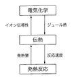
- the simulation method may simulate the thermal phenomenon by coupled analysis of the electrochemical reaction in the power storage device and the exothermic reaction in the material decomposition reaction of the power storage device.
- the exothermic reaction and Joule exothermic reaction of a battery are not independent physical phenomena, but proceed while being related to each other through physical phenomena such as heat transfer. Therefore, by performing coupled analysis, the phenomenon occurring inside the battery can be accurately detected.
- the behavior of the battery can be simulated by reflecting it.
- the simulation method formulates the relationship between the temperature and the calorific value obtained by the differential thermal analysis of the power storage device, and based on the relational expression between the temperature and the calorific value obtained by the formulation, the heat generation in the material decomposition reaction of the power storage device You may calculate the speed. According to this configuration, since the relationship between the temperature and the calorific value obtained by the differential thermal analysis is formulated, it is possible to save the trouble of converting the relationship between the temperature and the calorific value into the relationship between the time and the calorific value.
- the simulation method accepts simulation conditions related to the power storage device, and simulates the generation of gas accompanying the material decomposition reaction of the power storage device based on the accepted simulation conditions. If an event such as an internal short circuit occurs in the power storage device and the safety mechanism does not function properly, the material decomposition reaction may proceed and high-temperature gas may be ejected from the inside of the power storage device. In this simulation method, it is possible to simulate the generation of gas due to the material decomposition reaction.
- At least one of the gas generation rate and the heat generation rate may be calculated based on the reaction rate of the material decomposition reaction.
- the gas generation rate may be calculated to be proportional to the reaction rate of the material decomposition reaction.
- at least one of the gas generation rate and the calorific value generation rate is calculated based on the reaction rate of the material decomposition reaction.
- the simulation device includes a reception unit that receives simulation conditions related to the power storage device, a simulation execution unit that calculates a short-circuit current based on the received simulation conditions and simulates a thermal phenomenon from the power storage device to the outside, and the simulation execution unit. It is provided with an output unit that outputs a simulation result based on the above or a simulation program based on the simulation conditions. According to this configuration, it is possible to simulate the thermal phenomenon from the power storage device to the outside based on the received simulation conditions.
- the thermal phenomenon from the power storage device to the outside includes, for example, a heat generation phenomenon due to a material decomposition reaction due to an internal short circuit or an external short circuit, a heat generation phenomenon due to a material decomposition reaction when the power storage device is heated from the outside, and a gas due to heat generation of the power storage device. Including the occurrence of.
- This simulation device calculates the heat generation rate of the power storage device, the gas generation rate, etc. based on the simulation conditions.
- the computer program causes the computer to present a user interface that accepts simulation conditions related to the power storage device, calculates a short-circuit current based on the received simulation conditions, and executes a process of simulating a thermal phenomenon from the power storage device to the outside. ..
- the thermal phenomenon from the power storage device to the outside includes, for example, a heat generation phenomenon due to a material decomposition reaction due to an internal short circuit or an external short circuit, a heat generation phenomenon due to a material decomposition reaction when the power storage device is heated from the outside, and a gas due to heat generation of the power storage device. Including the occurrence of.
- This computer program calculates the heat generation rate of the power storage device, the gas generation rate, etc. based on the simulation conditions.
- FIG. 1 is a schematic diagram illustrating the overall configuration of the simulation system according to the embodiment.
- the simulation system according to the present embodiment includes a server device 100 and a client device 200 that are communicably connected to each other via the communication network N.
- the server device 100 simulates a thermal phenomenon appearing to the outside from the power storage device in response to a request from the client device 200, and provides the simulation result to the client device 200.
- the power storage device to be simulated includes a rechargeable power storage element (cell) such as a lead storage battery, a secondary battery such as a lithium ion battery, or a capacitor.
- a rechargeable power storage element such as a lead storage battery, a secondary battery such as a lithium ion battery, or a capacitor.
- the power storage device to be simulated includes a module in which a plurality of cells are connected in series, a bank in which a plurality of modules are connected in series (series connection battery group), and a domain in which a plurality of banks are connected in parallel (parallel connection battery group). Etc. may be included.
- the client device 200 is a terminal device such as a personal computer, a smartphone, or a tablet terminal used by a user.
- Software (application program) for accessing the server device 100 is installed in the client device 200.
- the server device 100 receives the access from the client device 200, for example, the server device 100 performs user authentication based on the user ID and password, and when the user authentication is successful, the server device 100 provides an appropriate service to the client device 200.
- the server device 100 After user authentication, the server device 100 according to the present embodiment transmits an interface screen for accepting various inputs by the user of the client device 200 to the client device 200.
- This interface screen includes, for example, a reception screen for accepting simulation conditions.
- the server device 100 transmits the simulation result executed based on the received conditions to the client device 200.
- the simulation result transmitted by the server device 100 to the client device 200 includes numerical data, graphs, and other data obtained as the execution result of the simulation.
- the simulation result transmitted by the server device 100 to the client device 200 may include a mathematical model obtained as a result of executing the simulation or a simulation program based on the simulation conditions.
- the client device 200 receives the simulation conditions, transmits the received simulation conditions and the like to the server device 100, and executes the simulation.
- the server device 100 may accept the simulation conditions, execute the simulation based on the accepted simulation conditions, and display the simulation results on the server device 100.
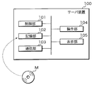
- FIG. 2 is a block diagram illustrating the internal configuration of the server device 100.
- the server device 100 includes a control unit 101, a storage unit 102, a communication unit 103, an operation unit 104, and a display unit 105.
- the control unit 101 is composed of a CPU (Central Processing Unit), a ROM (Read Only Memory), a RAM (Random Access Memory), and the like.
- the CPU included in the control unit 101 expands and executes various computer programs stored in the ROM or the storage unit 102 on the RAM, thereby causing the entire device to function as the simulation device of the present application.
- the server device 100 is only one embodiment of the simulation device, and may be any information processing device communicatively connected to the client device 200.
- the control unit 101 is not limited to the above configuration, and may be an arbitrary processing circuit or arithmetic circuit including a plurality of CPUs, a multi-core CPU, a GPU (Graphics Processing Unit), a microcomputer, a volatile or non-volatile memory, and the like. There may be.
- the control unit 101 may have functions such as a timer for measuring the elapsed time from giving the measurement start instruction to the measurement end instruction, a counter for counting the number, and a clock for outputting the date and time information.
- the storage unit 102 includes a storage device that uses an HDD (Hard Disk Drive), SSD (Solid State Drive), or the like.
- the storage unit 102 stores various computer programs executed by the control unit 101, data necessary for executing the computer programs, and the like.
- the computer program stored in the storage unit 102 includes a simulation program that simulates a thermal phenomenon that appears to the outside from the power storage device.
- the simulation program is, for example, an execution binary.
- the theoretical formula that is the basis of the simulation program is described by an algebraic equation or a differential equation that represents a thermal phenomenon that appears outside the power storage device.
- the simulation program may be a single computer program or a group of programs composed of a plurality of computer programs.
- the simulation programs are MATLAB (registered trademark), Amesim (registered trademark), Twin Builder (registered trademark), MATLAB & Simulink (registered trademark), Sampler (registered trademark), ANSYS (registered trademark), Abaqus (registered trademark), Modelica (registered trademark). It may be described by commercially available numerical analysis software or programming language such as Trademark), VHDL-AMS®, C language, C ++, Java®.
- the numerical analysis software may be a circuit simulator called 1D-CAE, or a simulation such as a finite element method or a finite volume method using a 3D shape.
- a degenerate model (ROM: Reduced-Order Model) based on these may be used.
- the program stored in the storage unit 102 may be provided by a non-temporary recording medium M in which the program is readablely recorded.
- the recording medium M is, for example, a portable memory such as a CD-ROM, a USB (Universal Serial Bus) memory, an SD (Secure Digital) card, a micro SD card, and a compact flash (registered trademark).
- the control unit 101 reads a program from the recording medium M using a reading device (not shown), and installs the read program in the storage unit 102.
- the program stored in the storage unit 102 may be provided by communication via the communication unit 103. In this case, the control unit 101 acquires a program through the communication unit 103, and installs the acquired program in the storage unit 102.
- the storage unit 102 may store a mathematical model obtained as a result of the simulation.
- a mathematical model is, for example, an executable code executed by a programming language or numerical analysis software.
- the mathematical model may be definition information or a library file referenced by a programming language or numerical analysis software.
- the storage unit 102 may have a battery table that stores information of a power storage device (for example, a secondary battery) in association with a user ID.
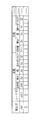
- FIG. 3 is a conceptual diagram showing an example of a battery table.
- the battery table stores, for example, a battery ID that identifies a battery, a user ID that identifies a user, and battery information in association with each other.
- the battery information registered in the battery table includes, for example, positive electrode and negative electrode information, electrolytic solution information, current collector information, and the like.
- the information on the positive electrode and the negative electrode is information such as the active material name, thickness, width, depth, and open circuit potential of the positive electrode and the negative electrode.
- the information on the electrolytic solution and the current collector is information on the ion species, transport number, mass diffusivity, conductivity, and the like.
- the battery table may include links that refer to information such as physical properties, operating conditions, and circuit configurations of the power storage device.
- the information stored in the battery table may be registered by the administrator of the server device 100 or may be registered by the user via the client device 200.
- the information stored in the battery table is used as part of the simulation conditions when simulating the thermal phenomenon of the power storage device.
- the communication unit 103 includes an interface for communicating with the client device 200 through the communication network N.
- the communication unit 103 transmits the input information to the client device 200 and controls the information received from the client device 200 through the communication network N. Output to unit 101.
- the operation unit 104 is provided with an input interface such as a keyboard and a mouse, and accepts operations by the user.
- the display unit 105 includes a liquid crystal display device and the like, and displays information to be notified to the user.
- the server device 100 is configured to include the operation unit 104 and the display unit 105, but the operation unit 104 and the display unit 105 are not indispensable, and the operation is accepted through a computer connected to the outside of the server device 100. , The information to be notified may be output to an external computer.
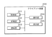
- FIG. 4 is a block diagram illustrating the internal configuration of the client device 200.
- the client device 200 is a personal computer, a smartphone, a tablet terminal, or the like, and includes a control unit 201, a storage unit 202, a communication unit 203, an operation unit 204, and a display unit 205.
- the control unit 201 is composed of a CPU, ROM, RAM, and the like.
- the CPU included in the control unit 201 executes control of the entire device by expanding and executing various computer programs stored in the ROM or the storage unit 202 on the RAM.
- the control unit 201 is not limited to the above configuration, and may be an arbitrary processing circuit or arithmetic circuit including a plurality of CPUs, a multi-core CPU, a microcomputer, and the like.
- the control unit 201 may have functions such as a timer for measuring the elapsed time from giving the measurement start instruction to the measurement end instruction, a counter for counting the number, and a clock for outputting the date and time information.
- the storage unit 202 is composed of a non-volatile memory such as EEPROM (Electronically Erasable Programmable Read Only Memory), and stores various computer programs and data.
- the computer program stored in the storage unit 202 includes a general-purpose or dedicated application used for exchanging information with the server device 100.
- An example of a general-purpose application program is a web browser. When accessing the server device 100 using a web browser, it is preferable to perform user authentication using a user ID and an authentication code, and communication between the server device 100 and the client device 200 only when the user authentication is successful. Should be allowed.
- the communication unit 203 includes an interface for communicating with the server device 100 through the communication network N.
- the communication unit 203 transmits the input information to the server device 100 and controls the information received from the server device 100 through the communication network N. Output to unit 201.
- the operation unit 204 is provided with an input interface such as a keyboard, mouse, and touch panel, and accepts operations by the user.
- the display unit 205 includes a liquid crystal display device and the like, and displays information to be notified to the user.
- the client device 200 is provided with the operation unit 204, but the client device 200 may be connected to an input interface such as a keyboard and a mouse.
- the server device 100 When simulating the thermal phenomenon associated with the internal short circuit of the power storage device, the server device 100 receives information related to the location where the internal short circuit occurs and the resistance value of the short circuit portion as simulation conditions. At this time, the server device 100 may display a reception screen for accepting the simulation conditions on the display unit 205 of the client device 200 and accept the simulation conditions through the displayed reception screen.
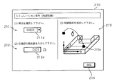
- FIG. 5 is a schematic diagram showing an example of a reception screen that accepts simulation conditions.
- the reception screen 210 shown in FIG. 5 includes a selection field 211 for selecting a battery to be simulated, an input field 212 for inputting information related to the resistance value of the short circuit portion, and a designation field 213 for designating a location where an internal short circuit occurs.
- a pull-down menu 211a is arranged in the selection field 211, and the type of battery to be simulated is accepted by the pull-down menu 211a.
- An input box 212a is arranged in the input field 212, and receives an input of a resistance value by, for example, a numerical input using the operation unit 204.
- a three-dimensional schematic diagram of the power storage device (cell) and an icon 213a indicating the location where the internal short circuit occurs are displayed in order to receive the location where the internal short circuit occurs.
- a three-dimensional schematic diagram of the module, bank, or domain may be displayed and the short circuit location may be accepted in the displayed schematic diagram.
- the reception screen 210 receives the location where the internal short circuit occurs by the movement operation (drag operation) of the icon 213a using the operation unit 204.
- the input simulation conditions (information about the battery, information related to the resistance value of the short circuit, the location where the internal short circuit occurs) are transmitted from the client device 200 to the server device 100. Will be done.
- the server device 100 simulates the power storage device based on the simulation conditions transmitted from the client device 200.
- FIG. 6 is an explanatory diagram illustrating an outline of the simulation method.
- the server device 100 simulates the behavior of the power storage device based on the Joule heat generation and the heat generation reaction due to material decomposition.
- the exotherm may include enthalpy reaction heat (reversible reaction heat) and electrochemical reaction heat (irreversible reaction heat) associated with an electrochemical reaction.
- the server device 100 can use, for example, the Newman model for the electrochemical reaction.
- the Newman model is an electrochemical model that assumes that homogeneous and single-diameter spheres are closely aligned in the positive and negative electrodes.
- the Newman model is described by the Nernst-Planck equation, the charge conservation equation, the diffusion equation, the Butler-Volmer equation, and the Nernst equation described below.
- the Nernst-Planck equation is an equation for solving ion electrophoresis and ion diffusion in an electrolyte or a porous electrode, and is expressed by the following equation.
- the value in the bulk and the value in the porous body may be appropriately converted as a function of the porosity of the constituent material.
- i l is the liquid phase current density (A / m 2 )
- ⁇ l eff is the liquid phase conductivity (S / m)
- ⁇ l is the liquid phase potential (V)
- R is the gas constant (J / ( K ⁇ mol))
- T temperature (K)
- F is the Faraday constant (C / mol)
- f is the activity coefficient
- t + is a cation transport number
- i tot is the reaction current density per volume (A / m 3 ).
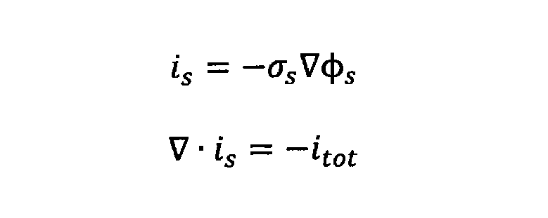
- the charge conservation formula is a formula that expresses electron conduction in an active material or a current collector foil, and is expressed by the following formula.
- phi s is the solid phase voltage (V)
- ⁇ s is the solid phase conductivity (S / m)
- i s is the solid phase current density (A / m 2)
- i tot the reaction current density per volume A / M 3 ).
- the diffusion equation is an equation that expresses the diffusion of active material in active particles, and is expressed by the following equation.
- C s is the active material concentration in the solid phase (mol / m 3 )
- t is the time (s)
- D s is the diffusion coefficient in the solid phase (m 2 / s).
- the Butler-Volmer equation is an equation that expresses the activation overvoltage in the charge transfer reaction that occurs at the interface between the solid phase and the liquid phase
- the Nernst equation is the definition equation of the open circuit potential, which are expressed by the following equations, respectively.
- i ioc is the reaction current density (A / m 2 )
- i 0 is the exchange current density (A / m 2 )
- ⁇ a and ⁇ c are the transition coefficients
- ⁇ is the activation overvoltage (V)
- E eq is.
- E 0 is the standard equilibrium potential (V)
- a ox is the oxidizing agent concentration (mol / m 3 )
- a red is the reducing agent concentration (mol / m 3 ).
- the exchange current density i 0 may be defined as a function of, for example, the ion concentration of the electrolytic solution or the concentration of the active material.
- Equation 4 a numerical value based on the experimental result may be used.
- the measured data of the charged state (SOC) and the open circuit potential (OCP or OCV) may be used instead of the Nernst equation.
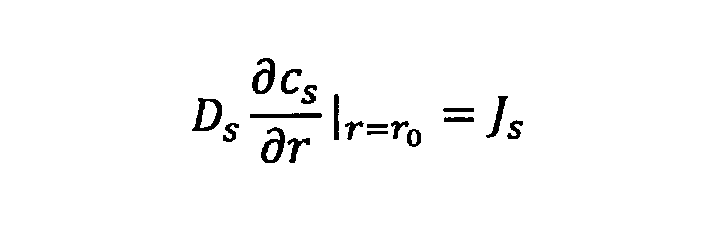
- Equation 5 shows the relational expression between the active material concentration in the solid phase and the active material flux involved in the charge transfer reaction on the surface of the active particles.
- r 0 represents the radius (m) of the active particle
- J s is the flux of the active material (mol / m 2 s).
- J s is the amount of active material per unit area and unit time that is lost and generated by the charge transfer reaction.
- Equation 6 is an equation describing the relationship between the flux J s of the active material and the reaction current density i loc .
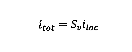
- Equation 7 is an equation describing the relationship between the reaction current density i loc and the reaction current density i tot per volume.
- the NEWman model is shown as an example of a model representing the electrochemical phenomenon of the power storage device.
- a single particle model in which the electrodes are represented by a single active particle, or a polynomial model in which the open circuit potential and internal resistance represented by the NTGK model are represented as functions of temperature and charge state (SOC). It may be used, or an equivalent circuit model may be used.
- SOC temperature and charge state
- the single-particle model is described in the non-patent document "Cycle Life Modeling of Lithium-Ion Batteries, Gang Ning and Blanco N. Popov, Journal of The Electrochemical" (1)
- a substance constituting a power storage device starts a reaction such as material decomposition when the temperature rises.
- the positive electrode and negative electrode materials of a lithium ion battery typically start to decompose at about 200 to 300 ° C., and generate gas with heat generation.
- the reaction can be expressed by the following Arrhenius reaction formula.
- r is the reaction rate (1 / s)
- k 0 is the reaction rate constant (1 / s)
- E a is the activation energy (J / mol)
- R is the gas constant (J / (K ⁇ mol)).
- T is the temperature (K)
- x f is the reaction rate
- p, q, C 0 are constants.
- Q is the exothermic density (W / m 3 )
- ⁇ is the density (kg / m 3 )
- H p is the heat of reaction (J / kg).
- the server device 100 analyzes the exothermic reaction associated with material decomposition and the Joule exothermic reaction in a coupled manner, and considers, for example, a change in electrical resistance due to a temperature rise from the power storage device to the outside. Simulate a thermal phenomenon.
- server device 100 The operation of the server device 100 and the client device 200 will be described below.
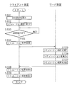
- FIG. 7 is a flowchart illustrating a procedure of processing executed by the server device 100 and the client device 200.
- the control unit 201 of the client device 200 receives the data for the display screen transmitted from the server device 100 after the user authentication, and displays the reception screen 210 for accepting the simulation conditions on the display unit 205 (step S101).
- the control unit 201 receives the simulation conditions through the reception screen 210 displayed on the display unit 205 (step S102). Specifically, the control unit 201 receives the selection of the battery type, the information related to the resistance value of the short-circuited portion in the internal short-circuit, and the location where the internal short-circuit occurs.
- control unit 201 determines whether or not the transmission instruction of the simulation condition has been received (step S103).
- the control unit 201 determines that the transmission instruction has been received.
- the control unit 201 waits until the transmission instruction is received.
- control unit 201 transmits the simulation conditions received in step S102 from the communication unit 203 to the server device 100 (step S104).
- the server device 100 receives the simulation conditions transmitted from the client device 200 by the communication unit 103 (step S105).
- the control unit 101 of the server device 100 executes the simulation based on the conditions received through the communication unit 103 (step S106).
- the control unit 101 simulates the thermal phenomenon of the power storage device by executing a simulation program corresponding to the behavior of the simulation target.
- the simulation conditions entered by the user are applied when the simulation program is executed.
- the control unit 101 couples the Joule thermal reaction and the exothermic reaction of material decomposition, calculates the electromotive force and internal resistance in the power storage device by, for example, the Newman model, and shows the reaction rate in the exothermic reaction in Equation 5 Arrhenius-type reaction. Calculate by the formula.
- control unit 101 can execute the current calculation in consideration of the change in the electric resistance due to the temperature rise, and is related to the phenomenon that the material generates heat due to the decomposition reaction due to the stoppage of energization due to the temperature rise and the progress of the exothermic reaction. It is possible to simulate the thermal phenomenon in the power storage device while doing so. For example, it may be assumed that the portion where the material decomposition reaction has progressed to a certain extent loses conductivity and the energization is stopped.
- the control unit 101 transmits the simulation result to the client device 200 through the communication unit 103 (step S107).
- the simulation result transmitted in step S107 may be numerical data, or may be a graph, contour diagram, moving image, or the like generated from the numerical data.
- the simulation result transmitted in step S107 may be a mathematical model obtained as a result of the simulation.
- the mathematical model is not just a theoretical model, but represents a model after simulation is performed on the selected power storage device and various parameters are adjusted.
- Mathematical models include, for example, MATLAB (registered trademark), Amesim (registered trademark), TwinBiller (registered trademark), MATLAB & Simulink (registered trademark), Sampler (registered trademark), ANSYS (registered trademark), Abaqus (registered trademark), and Moderna. It is provided in the format of commercially available numerical analysis software such as (registered trademark), VHDL-AMS (registered trademark), C language, C ++, Java (registered trademark), or libraries, modules, etc. used in programming languages.
- the client device 200 receives the simulation result transmitted from the server device 100 in the communication unit 203 (step S108).
- the control unit 201 of the client device 200 causes the display unit 205 to display the received simulation result (step S109).
- the server device 100 can simulate the heat phenomenon appearing to the outside from the power storage device in consideration of the heat generation reaction due to the material decomposition of the power storage device and the Joule heat generation. Even if the user is not familiar with physical phenomena in the power storage device, he / she can set a complicated simulation by inputting information related to the type of the power storage device, the location where the internal short circuit occurs, and the resistance value of the short circuit from the client device 200. It is possible to obtain the simulation result regarding the thermal phenomenon of the power storage device without.
- the server device 100 indicates information related to the resistance value in the external short circuit through the client device 200 (for example, a numerical value directly indicating the resistance value in the external short circuit.
- the resistance value in the external short circuit is indirectly indicated.
- the cause of the external short circuit (external short circuit between the positive and negative terminals by a tool such as a spanner, short circuit outside the battery due to the insulation (coating) destruction of the wiring, external short circuit due to a crash) It accepts the input of (short circuit, external short circuit due to switch failure, etc.))) and simulates the thermal phenomenon based on the information related to the resistance value of the received external short circuit.
- the control unit 101 of the server device 100 calculates the current flowing from the positive electrode terminal to the negative electrode terminal of the battery due to an external short circuit.
- control unit 101 simulates the heat phenomenon appearing to the outside from the power storage device and the power storage device by performing coupled analysis of the Joule heat accompanying the electric current and the exothermic reaction such as material decomposition in response to the generation of the Joule heat. can do.
- the thermal phenomenon when the power storage device is heated from the outside is simulated.
- the power storage device may be heated due to an abnormality in the surrounding environment (when a moving body equipped with the power storage device crashes, when a cooling device in the power storage device equipment fails, etc.).
- the behavior may differ depending on whether the side surface of the power storage device is heated or the top surface is heated.
- the power storage device is a pouch cell or a cylindrical cell.
- the behavior of the power storage device located inside and the power storage device located outside may differ due to the difference in distance from the heat source and the influence of heat buildup. is there. Therefore, during the simulation, the heating point of the power storage device by the heat source is accepted.
- the server device 100 receives simulation conditions including the heating location, the amount of heat, and the ambient temperature when the power storage device is heated from the outside through the client device 200.
- the heating location may be accepted via a user interface that includes a graphic display similar to FIG.
- the server device 100 simulates a thermal phenomenon based on the received simulation conditions.
- the control unit 101 of the server device 100 analyzes the material decomposition reaction that proceeds in response to the heat given from the outside by using the Arrhenius-type reaction formula to detect the thermal phenomenon that appears from the power storage device to the outside. Can be simulated.
- FIG. 8 is an explanatory diagram illustrating the components of the power storage device 1 according to the third embodiment.
- the power storage device 1 according to the third embodiment includes a wound electrode body 10v, a positive electrode terminal 11, a positive electrode current collector 11a, a negative electrode terminal 12, and a negative electrode current collector 12a, for example, in a hollow rectangular parallelepiped container 20. Be housed.
- the electrode body 10v includes, for example, a band-shaped negative electrode in which a negative electrode active material is provided on a negative electrode current collector foil made of copper foil, and a positive electrode active material on a positive electrode current collector foil made of aluminum foil arranged so as to be displaced in the width direction of the negative electrode.
- a separator made of a porous resin film is arranged between the band-shaped positive electrode and the provided band-shaped positive electrode, and the wound electrode body 10v is formed by winding these.
- the positive electrode current collector 11a electrically connects the positive electrode terminal 11 and the positive electrode (active material non-forming portion, positive electrode current collector foil) of the electrode body 10v.
- the negative electrode current collector 12a electrically connects the negative electrode terminal 12 and the negative electrode (active material non-forming portion, negative electrode current collector foil) of the electrode body 10v.
- the positive electrode current collector 11a is electrically connected to the positive electrode body 10v at at least one point, and the negative electrode current collector 12a is electrically connected to the negative electrode body 10v at at least one point.
- Various forms can be considered for the positions of the positive electrode current collector 11a and the negative electrode current collector 12a as long as the electrical connection between the positive electrode body 10v and the positive electrode and the negative electrode does not change. In the example of FIG.
- the direction of the winding center of the electrode body 10v is the X-axis direction on the paper surface.
- the direction of the winding center of the electrode body 10v may be the Y-axis direction or the Z-axis direction of the paper surface.
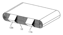
- FIG. 9 shows an electrode body of a wound cell having an electrode tab.
- the negative electrode is provided with a plurality of negative electrode tabs 12b (active material non-forming portions) at intervals on one side extending in the longitudinal direction of the strip-shaped negative electrode current collecting foil.
- the positive electrode is provided with a plurality of positive electrode tabs 11b (active material non-forming portions) at intervals on one side extending in the longitudinal direction of the strip-shaped positive electrode current collecting foil.
- a wound electrode body is formed by arranging a separator between the negative electrode and the positive electrode and winding these.
- the plurality of negative electrode tabs 12b and the plurality of positive electrode tabs 11b are bundled and electrically connected to a negative electrode current collector and a positive electrode current collector (not shown).
- a laminated cell a cell in which a laminated electrode body in which a plurality of sheet-shaped current collector foils are laminated is housed in a container
- short-circuiting is performed from electrodes other than the short-circuit layer only via a tab.
- the wound cell there are two types: a current flowing from the short-circuit layer through the tab (positive electrode tab 11b or negative electrode tab 12b) and a current flowing from the curved portion in the middle of the adjacent electrode. Therefore, in the wound cell, the calculation method used in the laminated cell cannot be diverted.
- the short-circuit current is calculated by virtually expanding the wound electrode body and expanding it.
- Typical examples performed in the simulation of an internal short circuit are a through short circuit represented by a nail piercing test and a partial short circuit represented by a nickel fragment mixing test. Hereinafter, each will be described in detail.
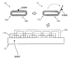
- FIG. 10 is an explanatory diagram illustrating a portion where a short-circuited portion appears due to a through-short circuit in the wound electrode body shown in FIG.
- the shapes and sizes of the wound electrode body 10, the positive electrode tab 11b, and the negative electrode tab 12b are shown in a deformed manner.
- the example of FIG. 10 shows a state in which a conductor such as a nail penetrates the wound electrode body in a wound cell having three turns, that is, a total of six layers.
- the developed model is a three-dimensional model in which the positive electrode current collector foil, the positive electrode active material, the separator, the negative electrode active material, and the negative electrode current collector foil are arranged from the front to the back of the paper.
- the positive electrode tab 11b exists in the same plane as the positive electrode current collecting foil (at the same position in the depth direction), and is electrically connected to the band-shaped positive electrode current collecting foil of the developed electrode body 10 at six points.
- the negative electrode tab 12b exists in the same plane as the negative electrode current collecting foil (at the same position in the depth direction), and is electrically connected to the band-shaped negative electrode current collecting foil of the developed electrode body 10 at 6 points. There is.
- the positive electrode tab 11b and the negative electrode tab 12b are not directly electrically connected.
- the portion connecting the plurality of positive electrode tabs 11b (plurality of negative electrode tabs 12b) in the lateral direction of the paper surface is a virtual conductive path representing the electrical connection of the plurality of tabs by binding the tabs as shown in FIG.
- FIG. 10 in the case of a through short circuit, when the wound electrode body is expanded, a plurality of short circuit portions appear in the longitudinal direction of the cell.
- the short-circuit phenomenon occurring inside the winding cell is appropriately expressed by calculating the current flowing from the tab (positive electrode tab 11b or negative electrode tab 12b) or the adjacent electrode toward each short-circuit portion. It is possible to accurately simulate the thermal phenomenon that appears to the outside from the winding cell.
- the wound electrode body has a bent portion of the electrode called a curved portion 10a shown in FIG. 10, but at this portion, physical property values (for example, electric conductivity, porosity, liquid phase conductivity) different from those of the flat portion 10b are obtained. Etc.) may be given.
- physical property values for example, electric conductivity, porosity, liquid phase conductivity
- Etc. may be given.
- an appropriate physical property value for example, electron conductivity of 1.0 ⁇ 10 10 S / m
- the example of the through-short circuit shown in FIG. 10 shows the case where a short circuit occurs in the center of the wound electrode body, but in this simulation method, the short-circuit position is not limited to the center of the wound electrode body. However, the calculation can be performed by the same modeling method even in the vicinity of the tab or the curved portion 10a, for example.
- FIG. 11 is an explanatory diagram illustrating a portion where a short-circuited portion appears due to a partial short-circuit in the wound electrode body.
- FIG. 11 for the sake of explanation, the shapes and sizes of the wound electrode body 10, the positive electrode tab 11b, and the negative electrode tab 12b (drawn by broken lines) are shown in a deformed manner.
- the example of FIG. 11 shows a state in which a conductor such as a nickel piece short-circuits a part of the wound electrode body.
- the developed model is a three-dimensional model in which the positive electrode current collector foil, the positive electrode active material, the separator, the negative electrode active material, and the negative electrode current collector foil are arranged from the front to the back of the paper.
- the short-circuit phenomenon occurring inside the winding cell is appropriately expressed by calculating the current flowing from the tab (positive electrode tab 11b or negative electrode tab 12b) or the adjacent electrode toward each short-circuit portion. It is possible to accurately simulate the thermal phenomenon that appears to the outside from the winding cell.
- the wound electrode body has a bent portion of the electrode called a curved portion 10a shown in FIG. 11, but at this portion, physical property values (for example, electric conductivity, porosity, liquid phase conductivity) different from those of the flat portion 10b are obtained. Etc.) may be given.
- For the virtual conductive path that represents the electrical connection by binding the tabs give an appropriate physical property value (for example, electron conductivity of 1.0 ⁇ 10 10 S / m) in consideration of the ease of convergence of the calculation. You may.
- the example of the partial short circuit shown in FIG. 11 shows the case where a short circuit occurs in the outermost peripheral layer at the center of the wound electrode body, but in this simulation method, the short circuit position is limited to the center of the wound electrode body. It does not have to be the outermost layer. Furthermore, there may be a plurality of short-circuited points. For example, even if the two winding layers are short-circuited or nickel pieces are mixed in a plurality of places, the calculation can be performed by the same modeling method by performing the simulation with the corresponding developed shapes.
- the safety simulation of the wound cell is a simulation of a short-circuit current in the unfolded shape of the wound electrode body and a simulation of heat transfer and exothermic reaction performed in the actual shape.
- the server device 100 uses the above-mentioned Arrhenius-type reaction formula of Equation 5 known as the Dahn model as a formula for describing the exothermic reaction of the material decomposition reaction.
- the control unit 101 of the server device 100 calculates the reaction rate x f using the Arrhenius-type reaction formula of Equation 5.
- control unit 101 fits the temperature-calorific value data obtained by the differential thermal analysis by a Lorentz function, a Gaussian function, or the like, and acquires a temperature-calorific value relational expression. Fitting with the Lorentz or Gaussian function is performed using an appropriate optimization tool.
- control unit 101 converts the exothermic density Q (T) obtained as a function of temperature into the exothermic density Q (t) expressed as a function of time by using the equation of the differential chain rule shown by the following equation. ..
- the factor represented by the time partial derivative of the temperature T is calculated in the process of calculation.
- the heat generation density Q (t) expressed as a function of time is calculated by using the graph of the temperature-calorific value relationship as it is, so that the temperature-calorific value relationship can be determined. , Eliminates the trouble of converting to the time-calorific value relationship.
- the material decomposition reaction may proceed and gas may be ejected from the inside of the power storage device.
- gas is generated by the reaction of oxygen desorbed from the positive electrode active material with the electrolytic solution due to the temperature rise.
- the housing of the power storage device is provided with a safety mechanism such as a burst valve that operates by pressure, and when the internal pressure rises due to the generation of gas inside the housing, the burst valve opens and the gas is ejected to the outside.
- this gas Since this gas has a high temperature, it causes burning of adjacent cells and burning of structural members.
- the gas ejected from the power storage device may contain harmful gas such as carbon monoxide, it is necessary to predict the ambient temperature in consideration of the temperature, flow velocity, and gas concentration. It is important for the safety design of the entire product including the power storage device.
- the server device 100 simulates gas generation based on the exothermic reaction caused by the material decomposition reaction.
- the server device 100 By calculating various amounts related to gas generation, for example, by using it as a boundary condition for thermo-fluid simulation, it can be utilized for thermal design and safety design of electric vehicles and power plants.
- the reactions involved in the generation of gas include, for example, gas generation by oxygen desorbed from the positive electrode active material and an electrolytic solution, and gas generation by thermal decomposition of an organic auxiliary agent contained in the electrode. .. These reactions are numbered 1, 2, ..., I, ... For convenience. In practice, it is difficult to analyze and consider the elementary reaction process related to battery gas generation in detail. Therefore, a method of separating reactions by collating a differential thermal analysis (DSC) chart or the result of gas amount measurement may be adopted.
- DSC differential thermal analysis
- v i is the normal volume of gas generated when the reaction i has completely proceeded
- x fi is the reaction rate of the reaction i.
- the control unit 101 calculates the pressure inside the power storage device housing. It is assumed that the gas inside the housing is an ideal gas.
- P 0 is the initial pressure inside the power storage device housing (Pa), and is usually 1 (atm).
- V gap is the volume of the gas existence region inside the power storage device housing (m 3 )
- T is the gas temperature (K)
- T 0 is the reference temperature (K).
- the burst valve of the power storage device is configured to open when the condition of P th ⁇ P in is satisfied.
- P th is the threshold value of the internal pressure at which the rupture valve opens. After the rupture valve opens, the gas generated by the reaction is discharged to the outside from the open rupture valve.
- q norm, tot is the volume velocity of normal gas generated (m 3 / s)
- v i is the volume of normal gas produced by the i-th reaction (m 3 )
- r i is the reaction rate of the i-th reaction (m 3 / s). 1 / s)
- v vent q norm, tot / S ⁇ (T / T) in consideration of thermal expansion. Calculated by 0 ).
- v vent is the ejection gas velocity (m / s) of the gas ejected from the opening of the burst valve. This value may be used as it is as a velocity boundary condition for gas ejection from the opening of the burst valve, or a parabolic velocity distribution may be given.
- the control unit 101 calculates the exothermic rate due to the exothermic reaction as well as the gas ejection rate.
- the method for calculating the heat generation rate may be the same as the method described in the first embodiment.
- the amount of heat generated by the exothermic reaction is appropriately divided between the ejected gas and the power storage device.
- a method of apportioning by the ratio of each heat capacity may be adopted assuming that the gas and the power storage device reach thermal equilibrium instantly.
- a proportional proportion of the amount of heat to the ejected gas and the power storage device may be given so as to be consistent with the experimental results.
- FIG. 12 is a schematic diagram showing a system (assembled battery) including a plurality of power storage devices
- FIG. 13 is a graphic display (moving image display) that visualizes a state in which a plurality of power storage devices discharge gas in a chain in the system of FIG. ).
- a gas in which the power storage device A raises the temperature due to an internal short circuit or the like the gas discharged from the power storage device A raises the temperature of the power storage device B, and the power storage device B discharges the gas in a chain reaction.
- this simulation method 1) The simulation conditions for the first power storage device are accepted, and the short-circuit current is calculated based on the received simulation conditions to simulate the thermal phenomenon from the first power storage device to the outside. 2) The thermal phenomenon from the second power storage device to the outside is simulated due to the heating of the second power storage device due to the heat phenomenon from the first power storage device to the outside.
- a simulation condition relating to the first power storage device is accepted, and the simulation condition includes a heating portion when the first power storage device is heated from the outside, and based on the received simulation condition, the first power storage device By simulating the thermal phenomenon from the first power storage device to the outside due to heating, 2) A simulation method is also conceivable in which the thermal phenomenon from the second power storage device to the outside is simulated due to the heating of the second power storage device due to the heat phenomenon from the first power storage device to the outside.
- These simulation methods may be realized as a simulation device or a computer program. By these simulation methods, it is possible to visualize the state of burning in a system including a plurality of power storage devices. It is possible to grasp which power storage device exhibits what kind of thermal phenomenon in time series, which power storage device and which power storage device interlock with each other to develop the thermal phenomenon.
- the target of the simulation is described with a focus on the heat effect of the power storage device on the outside, but the inside of the power storage device may be focused on.
- the gas ejected from the power storage device has the effect of suppressing the temperature rise of the power storage device. Therefore, it is possible to calculate the state inside the power storage device with exactly the same idea.
- the simulation method of the present application can be utilized for determining whether or not the burst valve opens due to gas generation due to material decomposition and an increase in internal pressure when the power storage device is exposed to a desired thermal condition. If the rupture valve opens and gas is ejected, the simulation method of the present application can also be used to examine whether or not burning to surrounding power storage devices occurs. Furthermore, for example, the effects of heat insulating materials and refractory materials for preventing burning can be confirmed by calculation, which is a means for strongly promoting product design based on the idea of model-based development.
- the embodiment in which the simulation is performed by the communication between the server and the client is illustrated, but the server administrator provides the simulation program to the client user by means of a storage medium such as a DVD-ROM, and the simulation is performed locally on the client terminal.
- a download format via communication may be used.
Landscapes
- Engineering & Computer Science (AREA)
- Computer Hardware Design (AREA)
- Physics & Mathematics (AREA)
- Theoretical Computer Science (AREA)
- Chemical Kinetics & Catalysis (AREA)
- General Chemical & Material Sciences (AREA)
- Electrochemistry (AREA)
- Chemical & Material Sciences (AREA)
- Evolutionary Computation (AREA)
- Geometry (AREA)
- General Engineering & Computer Science (AREA)
- General Physics & Mathematics (AREA)
- Manufacturing & Machinery (AREA)
- Microelectronics & Electronic Packaging (AREA)
- Secondary Cells (AREA)
Abstract
シミュレーション方法は、蓄電デバイスに関するシミュレーション条件を受付け、受付けたシミュレーション条件に基づき、短絡電流を計算して蓄電デバイスから外部への熱現象をシミュレートする。
Description
本発明は、コンピュータ実装されるシミュレーション方法、シミュレーション装置、及びコンピュータプログラムに関する。
近年、自動車業界を始めとした各業界で、MBD(モデルベース開発)が盛んに導入されており、シミュレーションに基づいた製品開発が浸透している(例えば、特許文献1を参照)。
モデルベース開発において、例えば、開発要素の1つである特定の蓄電デバイスについて熱的な安全性をシミュレートする場合が考えられる。蓄電デバイスの内部にて起こる物理現象や化学現象に応じて様々な条件設定をする必要がある。蓄電デバイスの安全性に関わる事象は、化学反応、伝熱、電流、電気化学、流体力学などの複数の物理現象が互いに関連しており、メカニズムや物性値が未知である場合も少なくない。このため、電池に詳しくない技術者が蓄電デバイスの安全性をシミュレートすることは困難である。しかし、昨今の電気自動車、再生可能エネルギ、スマートグリッドなどの目覚ましい開発進展を考え、高性能・高安全な蓄電デバイスに対する期待は大きく、シミュレーションを高度に活用した安全性設計の意義は大きい。
本発明は、斯かる事情に鑑みてなされたものであり、電池に詳しくない技術者であっても蓄電デバイスの熱現象を容易にシミュレートできるシミュレーション方法、シミュレーション装置、及びコンピュータプログラムを提供することを目的とする。
シミュレーション方法は、蓄電デバイスに関するシミュレーション条件を受付け、受付けたシミュレーション条件に基づき、短絡電流を計算して前記蓄電デバイスから外部への熱現象をシミュレートする。
シミュレーション装置は、蓄電デバイスに関するシミュレーション条件を受付ける受付部と、受付けたシミュレーション条件に基づき、短絡電流を計算して前記蓄電デバイスから外部への熱現象をシミュレートするシミュレーション実行部と、前記シミュレーション実行部によるシミュレーション結果または前記シミュレーション条件に基づくシミュレーションプログラムを出力する出力部とを備える。
コンピュータプログラムは、コンピュータに、蓄電デバイスに関するシミュレーション条件を受付けるユーザインタフェースを提示させ、受付けたシミュレーション条件に基づき、短絡電流を計算して前記蓄電デバイスから外部への熱現象をシミュレートする処理を実行させるためのコンピュータプログラムである。
上記構成によれば、電池に詳しくない技術者であっても蓄電デバイスの熱現象を容易にシミュレートできる。
シミュレーション方法は、蓄電デバイスに関するシミュレーション条件を受付け、受付けたシミュレーション条件に基づき、短絡電流を計算して前記蓄電デバイスから外部への熱現象をシミュレートする。外部とは、例えば蓄電デバイスまたは複数の蓄電デバイスからなる蓄電システムを収納したコンテナや、車両の蓄電池格納部、或いは蓄電デバイスを収納した建屋の外部の空間であってもよい。
この構成によれば、受付けたシミュレーション条件に基づき、蓄電デバイスから外部への熱現象をシミュレートできる。蓄電デバイスから外部への熱現象は、例えば、内部短絡や外部短絡に伴うジュール熱及び材料分解反応による発熱現象、蓄電デバイスを外部から加熱した場合の材料分解反応による発熱現象、及び蓄電デバイスの発熱に伴うガスの発生を含む。本シミュレーション方法は、蓄電デバイスの発熱速度、ガスの発生速度等をシミュレーション条件に基づき計算する。
この構成によれば、受付けたシミュレーション条件に基づき、蓄電デバイスから外部への熱現象をシミュレートできる。蓄電デバイスから外部への熱現象は、例えば、内部短絡や外部短絡に伴うジュール熱及び材料分解反応による発熱現象、蓄電デバイスを外部から加熱した場合の材料分解反応による発熱現象、及び蓄電デバイスの発熱に伴うガスの発生を含む。本シミュレーション方法は、蓄電デバイスの発熱速度、ガスの発生速度等をシミュレーション条件に基づき計算する。
シミュレーション方法は、外部端末を用いたユーザ認証の後に前記外部端末から送信されるシミュレーション条件を受信し、受信したシミュレーション条件に基づくシミュレーションの実行結果を前記外部端末へ送信してもよい。この構成によれば、ユーザが蓄電デバイスの挙動を表す理論に精通していない場合であっても、シミュレーション条件を受付けるだけで、蓄電デバイスの外部に現れる熱現象のシミュレーション結果またはシミュレーションプログラムをユーザに提供できる。
前記シミュレーション条件は、前記蓄電デバイスにおける内部短絡の発生箇所を含んでもよく、シミュレーション方法は、前記内部短絡に伴う前記熱現象をシミュレートしてもよい。前記シミュレーション条件は、短絡部の抵抗値に関連する情報を更に含んでもよい。短絡部の抵抗値に関連する情報は、内部短絡を生じさせた物質の名称(例えば、ニッケル、鉄)と形状(例えば、円形、四角形、それらのサイズ)、内部短絡のモード(例えば、クラッシュ、釘刺し、異物混入)などを含んでもよく、その情報から短絡部の抵抗値を計算できるものであることが好ましい。短絡部の抵抗値に関連する情報は、上述の間接的な情報に代えて、短絡部と蓄電デバイスを構成する部材(例えば正極集電箔など)との接触抵抗など、短絡部の抵抗値を直接的に示すものでもよい。この構成によれば、内部短絡の発生箇所を与えることによって、異なる発生箇所での内部短絡に伴う熱現象をシミュレートできる。
前記蓄電デバイスは、巻回電極体を含んでもよく、シミュレーション方法は、前記巻回電極体を仮想的に展開した状態にて短絡電流を計算してもよい。この構成によれば、巻回セルの構造を考慮して短絡電流を計算するので、貫通短絡又は部分短絡に応じた熱現象を的確にシミュレートできる。
前記シミュレーション条件は、前記蓄電デバイスの外部短絡における抵抗値に関連する情報を含んでもよく、シミュレーション方法は、前記外部短絡に伴う前記熱現象をシミュレートしてもよい。この構成によれば、外部短絡における抵抗値に関連する情報を与えることによって、外部短絡に伴う熱現象をシミュレートできる。
他の実施形態に係るシミュレーション方法は、蓄電デバイスに関するシミュレーション条件を受付け、前記シミュレーション条件は、前記蓄電デバイスを外部から加熱する際の加熱箇所を含み、受付けたシミュレーション条件に基づき、前記蓄電デバイスの加熱に伴う前記蓄電デバイスから外部への熱現象をシミュレートする。前記シミュレーション条件は、外部加熱の熱量を更に含んでもよい。前記シミュレーション条件は、環境温度を更に含んでもよい。この構成によれば、蓄電デバイスを外部から加熱する際の加熱箇所を与えることによって、加熱に伴う熱現象をシミュレートできる。
シミュレーション方法は、前記蓄電デバイスにおける電気化学反応と、前記蓄電デバイスの材料分解反応における発熱反応との連成解析により前記熱現象をシミュレートしてもよい。電池の発熱反応及びジュール発熱は独立した物理現象ではなく、伝熱といった物理現象を介して相互に関連しながら進行するので、連成解析を行うことにより、電池内部で起こっている現象を的確に反映させて電池の挙動をシミュレートすることができる。
シミュレーション方法は、前記蓄電デバイスの示差熱分析によって得られる温度と発熱量との関係を定式化し、定式化して得られる温度と発熱量との関係式に基づき、前記蓄電デバイスの材料分解反応における発熱速度を計算してもよい。この構成によれば、示差熱分析によって得られる温度と発熱量との関係を定式化するので、温度及び発熱量の関係を、時刻及び発熱量の関係に換算する手間が省ける。
他の実施形態に係るシミュレーション方法は、蓄電デバイスに関するシミュレーション条件を受付け、受付けたシミュレーション条件に基づき、前記蓄電デバイスの材料分解反応に伴うガスの発生をシミュレートする。蓄電デバイスにおいて内部短絡などの事象が発生し、安全機構がうまく機能しなかった場合、材料分解反応が進行して蓄電デバイスの内部から高温のガスが噴出する可能性がある。本シミュレーション方法では、材料分解反応に伴うガスの発生をシミュレートできる。
シミュレーション方法は、前記材料分解反応の反応速度に基づき、前記ガスの発生速度、及び熱量の発生速度の少なくとも1つを計算してもよい。前記ガスの発生速度は、前記材料分解反応の反応速度に比例するように計算されてもよい。この構成によれば、材料分解反応の反応速度に基づき、ガスの発生速度、及び熱量の発生速度の少なくとも1つが計算される。
シミュレーション装置は、蓄電デバイスに関するシミュレーション条件を受付ける受付部と、受付けたシミュレーション条件に基づき、短絡電流を計算して前記蓄電デバイスから外部への熱現象をシミュレートするシミュレーション実行部と、前記シミュレーション実行部によるシミュレーション結果または前記シミュレーション条件に基づくシミュレーションプログラムを出力する出力部とを備える。
この構成によれば、受付けたシミュレーション条件に基づき、蓄電デバイスから外部への熱現象をシミュレートできる。蓄電デバイスから外部への熱現象は、例えば、内部短絡や外部短絡に伴う材料分解反応による発熱現象、蓄電デバイスを外部から加熱した場合の材料分解反応による発熱現象、及び蓄電デバイスの発熱に伴うガスの発生を含む。本シミュレーション装置は、蓄電デバイスの発熱速度、ガスの発生速度等をシミュレーション条件に基づき計算する。
この構成によれば、受付けたシミュレーション条件に基づき、蓄電デバイスから外部への熱現象をシミュレートできる。蓄電デバイスから外部への熱現象は、例えば、内部短絡や外部短絡に伴う材料分解反応による発熱現象、蓄電デバイスを外部から加熱した場合の材料分解反応による発熱現象、及び蓄電デバイスの発熱に伴うガスの発生を含む。本シミュレーション装置は、蓄電デバイスの発熱速度、ガスの発生速度等をシミュレーション条件に基づき計算する。
コンピュータプログラムは、コンピュータに、蓄電デバイスに関するシミュレーション条件を受付けるユーザインタフェースを提示させ、受付けたシミュレーション条件に基づき、短絡電流を計算して前記蓄電デバイスから外部への熱現象をシミュレートする処理を実行させる。
この構成によれば、受付けたシミュレーション条件に基づき、蓄電デバイスから外部への熱現象をシミュレートできる。蓄電デバイスから外部への熱現象は、例えば、内部短絡や外部短絡に伴う材料分解反応による発熱現象、蓄電デバイスを外部から加熱した場合の材料分解反応による発熱現象、及び蓄電デバイスの発熱に伴うガスの発生を含む。本コンピュータプログラムは、蓄電デバイスの発熱速度、ガスの発生速度等をシミュレーション条件に基づき計算する。
この構成によれば、受付けたシミュレーション条件に基づき、蓄電デバイスから外部への熱現象をシミュレートできる。蓄電デバイスから外部への熱現象は、例えば、内部短絡や外部短絡に伴う材料分解反応による発熱現象、蓄電デバイスを外部から加熱した場合の材料分解反応による発熱現象、及び蓄電デバイスの発熱に伴うガスの発生を含む。本コンピュータプログラムは、蓄電デバイスの発熱速度、ガスの発生速度等をシミュレーション条件に基づき計算する。
以下、本発明をその実施の形態を示す図面に基づいて具体的に説明する。
(実施の形態1)
図1は実施の形態に係るシミュレーションシステムの全体構成を説明する模式図である。本実施の形態に係るシミュレーションシステムは、通信網Nを介して互いに通信可能に接続されるサーバ装置100とクライアント装置200とを備える。サーバ装置100は、クライアント装置200からの要求に応じて、蓄電デバイスから外部に現れる熱現象をシミュレートし、シミュレーション結果をクライアント装置200へ提供する。ここで、シミュレーション対象の蓄電デバイスは、鉛蓄電池、リチウムイオン電池等の二次電池、又はキャパシタ等の再充電可能な蓄電素子(セル)を含む。また、シミュレーション対象の蓄電デバイスは、複数のセルを直列に接続したモジュール、複数のモジュールを直列に接続したバンク(直列接続電池群)、複数のバンクを並列に接続したドメイン(並列接続電池群)等を含んでもよい。
(実施の形態1)
図1は実施の形態に係るシミュレーションシステムの全体構成を説明する模式図である。本実施の形態に係るシミュレーションシステムは、通信網Nを介して互いに通信可能に接続されるサーバ装置100とクライアント装置200とを備える。サーバ装置100は、クライアント装置200からの要求に応じて、蓄電デバイスから外部に現れる熱現象をシミュレートし、シミュレーション結果をクライアント装置200へ提供する。ここで、シミュレーション対象の蓄電デバイスは、鉛蓄電池、リチウムイオン電池等の二次電池、又はキャパシタ等の再充電可能な蓄電素子(セル)を含む。また、シミュレーション対象の蓄電デバイスは、複数のセルを直列に接続したモジュール、複数のモジュールを直列に接続したバンク(直列接続電池群)、複数のバンクを並列に接続したドメイン(並列接続電池群)等を含んでもよい。
クライアント装置200は、ユーザによって利用されるパーソナルコンピュータ、スマートフォン、タブレット端末などの端末装置である。クライアント装置200には、サーバ装置100にアクセスするためのソフトウェア(アプリケーションプログラム)がインストールされている。サーバ装置100は、クライアント装置200からのアクセスを受付けた際に例えばユーザID及びパスワードに基づくユーザ認証を行い、ユーザ認証に成功した場合、クライアント装置200に対して適宜のサービスを提供する。
本実施の形態に係るサーバ装置100は、ユーザ認証の後、クライアント装置200のユーザによる各種入力を受付けるためのインタフェース画面をクライアント装置200へ送信する。このインタフェース画面には、例えば、シミュレーション条件を受付けるための受付画面が含まれる。サーバ装置100は、受付けた条件に基づいて実行したシミュレーション結果をクライアント装置200へ送信する。
サーバ装置100がクライアント装置200に対して送信するシミュレーション結果は、シミュレーションの実行結果として得られる数値データ、グラフ等のデータを含む。サーバ装置100がクライアント装置200に対して送信するシミュレーション結果は、シミュレーションの実行結果として得られる数理モデル、または、シミュレーション条件に基づくシミュレーションプログラムを含んでもよい。
本実施の形態では、クライアント装置200においてシミュレーション条件を受付け、受付けたシミュレーション条件等をサーバ装置100へ送信してシミュレーションを実行する。代替的に、サーバ装置100において、シミュレーション条件を受付け、受付けたシミュレーション条件等に基づきシミュレーションを実行し、サーバ装置100にてシミュレーション結果を表示してもよい。
図2はサーバ装置100の内部構成を説明するブロック図である。サーバ装置100は、制御部101、記憶部102、通信部103、操作部104及び表示部105を備える。
制御部101は、CPU(Central Processing Unit)、ROM(Read Only Memory)、RAM(Random Access Memory)などにより構成される。制御部101が備えるCPUは、ROM又は記憶部102に記憶されている各種コンピュータプログラムをRAM上に展開して実行することにより、装置全体を本願のシミュレーション装置として機能させる。サーバ装置100は、シミュレーション装置の一実施形態に過ぎず、クライアント装置200と通信可能に接続された任意の情報処理装置であればよい。
制御部101は、上記の構成に限定されるものではなく、複数のCPU、マルチコアCPU、GPU(Graphics Processing Unit)、マイコン、揮発性又は不揮発性のメモリ等を備える任意の処理回路又は演算回路であってもよい。制御部101は、計測開始指示を与えてから計測終了指示を与えるまでの経過時間を計測するタイマ、数をカウントするカウンタ、日時情報を出力するクロック等の機能を備えていてもよい。
記憶部102は、HDD(Hard Disk Drive)、SSD(Solid State Drive)等を用いた記憶装置を備える。記憶部102には、制御部101によって実行される各種コンピュータプログラム、及びコンピュータプログラムの実行に必要なデータ等が記憶される。記憶部102に記憶されるコンピュータプログラムは、蓄電デバイスから外部に現れる熱現象をシミュレートするシミュレーションプログラムを含む。シミュレーションプログラムは、例えば実行バイナリである。シミュレーションプログラムの元となる理論式は、蓄電デバイスから外部に現れる熱現象を表す代数方程式又は微分方程式によって記述される。シミュレーションプログラムは単一のコンピュータプログラムであってもよく、複数のコンピュータプログラムから構成されるプログラム群であってもよい。シミュレーションプログラムは、MATLAB(登録商標)、Amesim(登録商標)、Twin Builder(登録商標)、MATLAB&Simulink(登録商標)、Simplorer(登録商標)、ANSYS(登録商標)、Abaqus(登録商標)、Modelica(登録商標)、VHDL-AMS(登録商標)、C言語、C++、Java(登録商標)などの市販の数値解析ソフトウェア又はプログラミング言語によって記述されてもよい。数値解析ソフトウェアは、1D-CAEと称される回路シミュレータ、または、3D形状による有限要素法や有限体積法などのシミュレーションであってもよい。これらに基づいた縮退モデル(ROM:Reduced-Order Model)を用いてもよい。
記憶部102に記憶されるプログラムは、当該プログラムを読み取り可能に記録した非一時的な記録媒体Mにより提供されてもよい。記録媒体Mは、例えば、CD-ROM、USB(Universal Serial Bus)メモリ、SD(Secure Digital)カード、マイクロSDカード、コンパクトフラッシュ(登録商標)などの可搬型メモリである。この場合、制御部101は、不図示の読取装置を用いて記録媒体Mからプログラムを読み取り、読み取ったプログラムを記憶部102にインストールする。記憶部102に記憶されるプログラムは、通信部103を介した通信により提供されてもよい。この場合、制御部101は、通信部103を通じてプログラムを取得し、取得したプログラムを記憶部102にインストールする。
記憶部102には、シミュレーションの結果として得られる数理モデルが記憶されてもよい。数理モデルは、例えば、プログラミング言語又は数値解析ソフトウェアにより実行される実行コードである。数理モデルは、プログラミング言語又は数値解析ソフトウェアにより参照される、定義情報若しくはライブラリファイルであってもよい。
記憶部102は、蓄電デバイス(例えば、二次電池)の情報をユーザIDに関連付けて記憶する電池テーブルを有していてもよい。図3は電池テーブルの一例を示す概念図である。電池テーブルは、例えば、電池を識別する電池ID、ユーザを識別するユーザID、及び電池情報を関連付けて記憶する。電池テーブルに登録される電池情報は、例えば、正極及び負極の情報、電解液の情報、集電体の情報などを含む。正極及び負極の情報とは、正極及び負極の活物質名、厚み、幅、奥行き、開回路電位などの情報である。電解液及び集電体の情報とは、イオン種、輸率、拡散係数、導電率などの情報である。電池テーブルには、蓄電デバイスの物理的性質、動作状態、回路構成等の情報を参照するリンクが含まれてもよい。電池テーブルに記憶される情報は、サーバ装置100の管理者によって登録されてもよく、クライアント装置200を介してユーザによって登録されてもよい。電池テーブルに記憶されている情報は、蓄電デバイスの熱現象をシミュレートする際に、シミュレーション条件の一部として利用される。
通信部103は、通信網Nを通じてクライアント装置200と通信を行うためのインタフェースを備える。通信部103は、クライアント装置200へ送信すべき情報が制御部101から入力された場合、入力された情報をクライアント装置200へ送信すると共に、通信網Nを通じて受信したクライアント装置200からの情報を制御部101へ出力する。
操作部104は、キーボード、マウスなどの入力インタフェースを備えており、ユーザによる操作を受付ける。表示部105は、液晶ディスプレイ装置などを備えており、ユーザに対して報知すべき情報を表示する。本実施の形態では、サーバ装置100が操作部104及び表示部105を備える構成としたが、操作部104及び表示部105は必須ではなく、サーバ装置100の外部に接続されたコンピュータを通じて操作を受付け、通知すべき情報を外部のコンピュータへ出力する構成であってもよい。
図4はクライアント装置200の内部構成を説明するブロック図である。クライアント装置200は、パーソナルコンピュータ、スマートフォン、タブレット端末等であり、制御部201、記憶部202、通信部203、操作部204及び表示部205を備える。
制御部201は、CPU、ROM、RAMなどにより構成される。制御部201が備えるCPUは、ROM又は記憶部202に記憶されている各種コンピュータプログラムをRAM上に展開して実行することにより、装置全体の制御を実行する。
制御部201は、上記の構成に限定されるものではなく、複数のCPU、マルチコアCPU、マイコン等を含む任意の処理回路又は演算回路であってもよい。制御部201は、計測開始指示を与えてから計測終了指示を与えるまでの経過時間を計測するタイマ、数をカウントするカウンタ、日時情報を出力するクロック等の機能を備えていてもよい。
記憶部202は、EEPROM(Electronically Erasable Programmable Read Only Memory)などの不揮発性メモリにより構成されており、各種コンピュータプログラム及びデータを記憶する。記憶部202に記憶されるコンピュータプログラムは、サーバ装置100と情報の授受を行うために用いられる汎用又は専用のアプリケーションを含む。汎用のアプリケーションプログラムの一例は、ウェブブラウザである。ウェブブラウザを用いてサーバ装置100にアクセスする場合、ユーザID及び認証コードを用いたユーザ認証を行うことが好ましく、ユーザ認証に成功した場合にのみ、サーバ装置100とクライアント装置200との間の通信を許可すればよい。
通信部203は、通信網Nを通じてサーバ装置100と通信を行うためのインタフェースを備える。通信部203は、サーバ装置100へ送信すべき情報が制御部201から入力された場合、入力された情報をサーバ装置100へ送信すると共に、通信網Nを通じて受信したサーバ装置100からの情報を制御部201へ出力する。
操作部204は、キーボード、マウス、タッチパネルなどの入力インタフェースを備えており、ユーザによる操作を受付ける。表示部205は、液晶ディスプレイ装置などを備えており、ユーザに対して報知すべき情報を表示する。本実施の形態では、クライアント装置200が操作部204を備える構成としたが、クライアント装置200にキーボード、マウス等の入力インタフェースが接続される構成であってもよい。
以下、サーバ装置100において、蓄電デバイスの内部短絡に伴う熱現象をシミュレートする構成について説明する。
サーバ装置100は、蓄電デバイスの内部短絡に伴う熱現象をシミュレートする場合、シミュレーション条件として、内部短絡の発生箇所、及び短絡部の抵抗値に関連する情報を受付ける。このとき、サーバ装置100は、シミュレーション条件を受付けるための受付画面をクライアント装置200の表示部205に表示させ、表示させた受付画面を通じてシミュレーション条件を受付けてもよい。
図5はシミュレーション条件を受付ける受付画面の一例を示す模式図である。図5に示す受付画面210は、シミュレーション対象の電池を選択する選択欄211、短絡部の抵抗値に関連する情報を入力する入力欄212、及び、内部短絡の発生箇所を指定する指定欄213を備える。選択欄211には、プルダウンメニュー211aが配置され、プルダウンメニュー211aによってシミュレーション対象の電池の種類を受付ける。入力欄212には、入力ボックス212aが配置され、例えば操作部204を用いた数値入力により、抵抗値の入力を受付ける。指定欄213には、内部短絡の発生箇所を受付けるために、蓄電デバイス(セル)の立体的な模式図と、内部短絡の発生箇所を示すアイコン213aとが表示される。代替的に、モジュール、バンク、又はドメインの立体的な模式図を表示し、表示した模式図において短絡箇所を受け付けてもよい。受付画面210は、操作部204を用いたアイコン213aの移動操作(ドラッグ操作)により、内部短絡の発生箇所を受付ける。
受付画面210において、送信ボタン214が操作された場合、入力されたシミュレーション条件(電池に関する情報、短絡部の抵抗値に関連する情報、内部短絡の発生箇所)がクライアント装置200からサーバ装置100へ送信される。サーバ装置100は、クライアント装置200から送信されるシミュレーション条件に基づき、蓄電デバイスのシミュレーションを行う。
以下、蓄電デバイスのシミュレーション手法について説明する。
図6はシミュレーション手法の概略を説明する説明図である。本実施の形態に係るサーバ装置100は、ジュール発熱と、材料分解による発熱反応とに基づき、蓄電デバイスの挙動をシミュレートする。発熱には、この他に電気化学反応に伴うエンタルピー反応熱(可逆反応熱)、電気化学反応熱(不可逆反応熱)を含めてもよい。
図6はシミュレーション手法の概略を説明する説明図である。本実施の形態に係るサーバ装置100は、ジュール発熱と、材料分解による発熱反応とに基づき、蓄電デバイスの挙動をシミュレートする。発熱には、この他に電気化学反応に伴うエンタルピー反応熱(可逆反応熱)、電気化学反応熱(不可逆反応熱)を含めてもよい。
サーバ装置100は、電気化学反応に関して、例えばNewmanモデルを用いることができる。Newmanモデルは、正極および負極の電極において、均質かつ単一径の球が近接して並んでいると想定する電気化学モデルである。Newmanモデルは、以下において説明するNernst-Planck式、電荷保存式、拡散方程式、Butler-Volmer式、及びNernst式により記述される。
Nernst-Planck式は、電解質や多孔電極におけるイオン泳動とイオン拡散とを解くための方程式であり、次式により表される。以降の数1から数4に表される各種パラメータは、構成材料の気孔率の関数として、バルクでの値と多孔体での値とが適宜換算されるようになっていてもよい。

ここで、il は液相電流密度(A/m2 )、σl,effは液相伝導率(S/m)、φl は液相電位(V)、Rは気体定数(J/(K・mol))、Tは温度(K)、Fはファラデー定数(C/mol)、fは活量係数、Cl は電解質のイオン濃度(mol/m3 )、t+ はカチオン輸率、itot は体積あたり反応電流密度(A/m3 )である。
電荷保存式は、活物質や集電箔での電子伝導を表す式であり、次式により表される。
ここで、φs は固相電位(V)、σs は固相伝導率(S/m)、is は固相電流密度(A/m2 )、itot は体積あたり反応電流密度(A/m3 )である。
拡散方程式は、活粒子中での活物質の拡散を表す方程式であり、次式により表される。
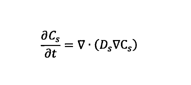
ここで、Cs は固相中の活物質濃度(mol/m3 )、tは時刻(s)、Ds は固相中の拡散係数(m2 /s)である。
Butler-Volmer式は、固相と液相との界面で起こる電荷移動反応での活性化過電圧を表す式、Nernst式は、開回路電位の定義式であり、それぞれ次式により表される。
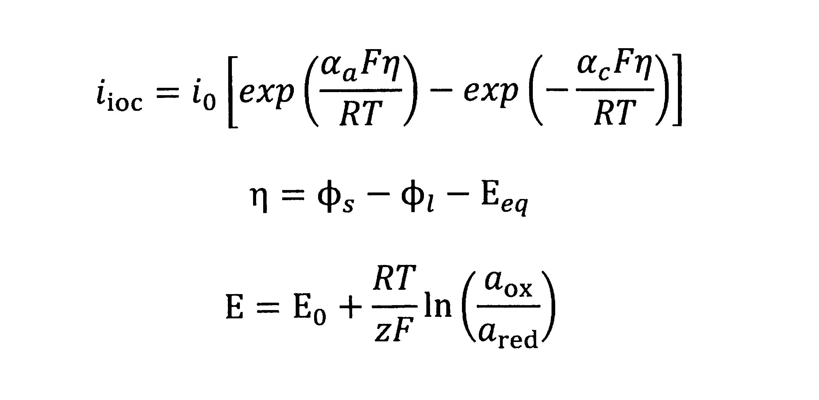
ここで、iioc は反応電流密度(A/m2 )、i0 は交換電流密度(A/m2 )、αa ,αc は移行係数、ηは活性化過電圧(V)、Eeqは平衡電位(V)、E0 は標準平衡電位(V)、aox は酸化剤濃度(mol/m3 )、ared は還元剤濃度(mol/m3 )である。交換電流密度i0 は、例えば電解液のイオン濃度や活物質の濃度の関数として定義してもよい。数4に記載した理論式ではなく、実験結果に基づいた数値を用いてもよい。例えばリチウムイオン二次電池の開回路電位においては、Nernst式に代替して、充電状態(SOC)と開回路電位(OCPまたはOCV)の実測データを用いてもよい。
数5に活粒子の表面における、固相中の活物質濃度と電荷移動反応に関わる活物質フラックスの関係式を示す。r0 は活粒子の半径(m)を表し、Js は活物質のフラックス(mol/m2 s)である。換言すれば、Js は電荷移動反応によって消失生成する、単位面積単位時間当たりの活物質の量である。
数6は、活物質のフラックスJs と反応電流密度iloc との関係を述べた式である。

数7は、反応電流密度iloc と体積あたり反応電流密度itot との関係を述べた式である。
本実施の形態では、蓄電デバイスの電気化学現象を表すモデルの一例としてNewmanモデルを示した。代替的には、電極を単一の活粒子で表現する単粒子モデルや、NTGKモデルに代表されるような開回路電位及び内部抵抗を温度及び充電状態(SOC)の関数として表した多項式モデルを用いてもよく、等価回路モデルを使用してもよい。単粒子モデルについては非特許文献『Cycle Life Modeling of Lithium-Ion Batteries , Gang Ning and Branko N. Popov,Journal of The Electrochemical Society, 151 (10) A1584-A1591 (2004)』に詳しく記載されている。
続いて、材料分解により生じる発熱反応について説明する。蓄電デバイスを構成する物質は、昇温により材料分解などの反応が開始することが知られている。例えばリチウムイオン電池の正極や負極材料は、典型的には200~300℃程度になると、材料分解が始まり、発熱と共にガスを生じる。このような温度依存性のある反応速度を表すため、当該反応を以下のようなアレニウス反応式で表現することができる。
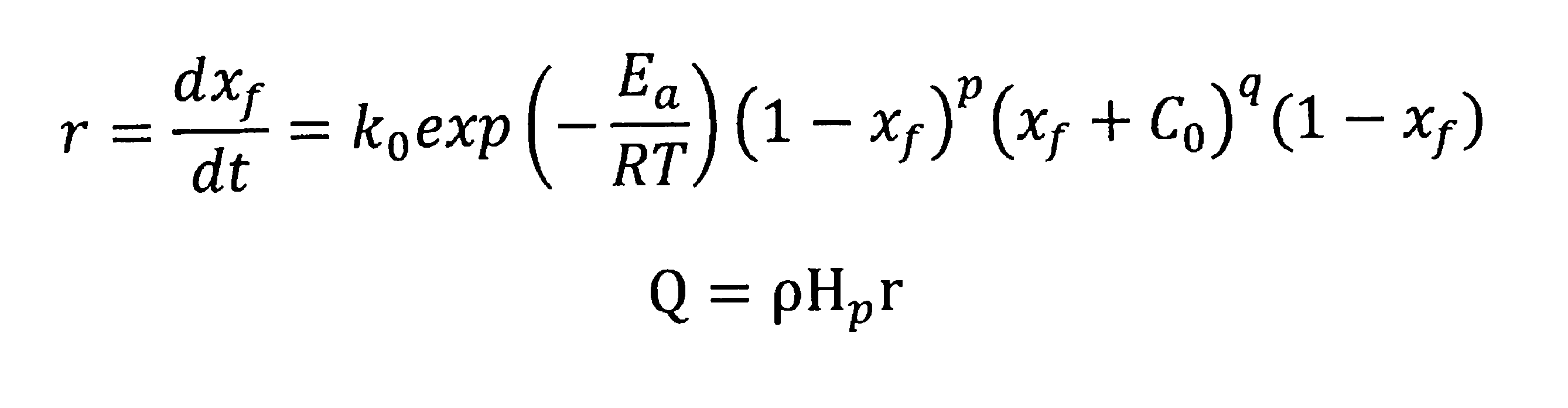
ここで、rは反応速度(1/s)、k0 は反応速度定数(1/s)、Ea は活性化エネルギ(J/mol)、Rは気体定数(J/(K・mol))、Tは温度(K)、xf は反応率、p,q,C0 は定数である。Qは発熱密度(W/m3 )、ρは密度(kg/m3 )、Hp は反応熱(J/kg)である。
蓄電デバイスにおいて、内部短絡が発生した場合、蓄電デバイス全体から短絡部に向かって電流が流れ込む。この内部短絡に伴う電流によりジュール熱が発生する。ジュール熱の発生に応じて、前記の材料分解などの発熱反応が進行する。この発熱反応によって昇温した場合、電気抵抗が変化するので、短絡部に流れ込む電流の大きさも変化する。以上のように、ジュール発熱と材料分解発熱反応とは独立した物理現象ではなく、伝熱といった物理現象を介して相互に関連しながら進行する。
そこで、本実施の形態に係るサーバ装置100は、材料分解に伴う発熱反応と、ジュール発熱とを連成させて解析し、例えば昇温による電気抵抗の変化を考慮して蓄電デバイスから外部への熱現象をシミュレートする。
以下、サーバ装置100及びクライアント装置200の動作について説明する。
図7はサーバ装置100及びクライアント装置200が実行する処理の手順を説明するフローチャートである。クライアント装置200の制御部201は、ユーザ認証の後にサーバ装置100から送信される表示画面用のデータを受信し、シミュレーション条件を受付けるための受付画面210を表示部205に表示する(ステップS101)。制御部201は、表示部205に表示した受付画面210を通じて、シミュレーション条件を受付ける(ステップS102)。具体的には、制御部201は、電池の種別の選択、内部短絡における短絡部の抵抗値に関連する情報、および、内部短絡の発生箇所を受付ける。
次いで、制御部201は、シミュレーション条件の送信指示を受付けたか否かを判断する(ステップS103)。制御部201は、図5に示す受付画面210において、送信ボタン214が操作された場合、送信指示を受付けたと判断する。送信指示を受け付けていない場合(S103:NO)、制御部201は、送信指示を受付けるまで待機する。
送信指示を受付けたと判断した場合(S103:YES)、制御部201は、ステップS102で受付けたシミュレーション条件を通信部203よりサーバ装置100へ送信する(ステップS104)。
サーバ装置100は、クライアント装置200から送信されるシミュレーション条件を通信部103にて受信する(ステップS105)。サーバ装置100の制御部101は、通信部103を通じて受信した条件に基づき、シミュレーションを実行する(ステップS106)。このとき、制御部101は、シミュレーション対象の挙動に対応するシミュレーションプログラムを実行することによって、蓄電デバイスの熱現象をシミュレートする。ユーザによって入力されたシミュレーション条件は、シミュレーションプログラムを実行する際に適用される。
蓄電デバイスにおいて、内部短絡が発生した場合、蓄電デバイス全体から短絡部に向かって電流が流れ込む。この内部短絡に伴う電流によりジュール熱が発生する。ジュール熱の発生に応じて、材料分解などの発熱反応が進行する。制御部101は、ジュール熱反応と材料分解の発熱反応とを連成させ、蓄電デバイスにおける起電力及び内部抵抗などを例えばNewmanモデルにより計算し、発熱反応における反応速度を数5に示すアレニウス型反応式により計算する。以上により、制御部101は、昇温による電気抵抗の変化を考慮して電流計算を実行することができ、昇温による通電の停止、発熱反応の進行により材料が分解反応により発熱する現象を関連させながら蓄電デバイスにおける熱現象をシミュレートすることができる。例えば、材料分解反応が一定程度進行した部位は導電性を失い、通電が停止すると仮定してもよい。
シミュレーションが完了した場合、制御部101は、通信部103を通じて、シミュレーション結果をクライアント装置200へ送信する(ステップS107)。ステップS107で送信するシミュレーション結果は、数値データであってもよく、数値データから生成したグラフ、コンター図及び動画などであってもよい。ステップS107で送信するシミュレーション結果は、シミュレーションの結果として得られる数理モデルであってもよい。数理モデルは、単なる理論モデルではなく、選択された蓄電デバイスについてシミュレーションが実行され、各種のパラメータが調整された後のモデルを表す。数理モデルは、例えば、MATLAB(登録商標)、Amesim(登録商標)、Twin Builder(登録商標)、MATLAB&Simulink(登録商標)、Simplorer(登録商標)、ANSYS(登録商標)、Abaqus(登録商標)、Modelica(登録商標)、VHDL-AMS(登録商標)、C言語、C++、Java(登録商標)などの市販の数値解析ソフトウェア又はプログラミング言語で用いられるライブラリ、モジュール等のフォーマットにより提供される。
クライアント装置200は、サーバ装置100から送信されるシミュレーション結果を通信部203にて受信する(ステップS108)。クライアント装置200の制御部201は、受信したシミュレーション結果を表示部205に表示させる(ステップS109)。
以上のように、本実施の形態では、サーバ装置100は、蓄電デバイスの材料分解による発熱反応と、ジュール発熱とを考慮して、蓄電デバイスから外部に現れる熱現象をシミュレートすることができる。ユーザは、蓄電デバイスにおける物理現象について詳しくなくても、クライアント装置200から蓄電デバイスの種類、内部短絡の発生箇所、及び短絡部の抵抗値に関連する情報を入力することによって、複雑なシミュレーションの設定なしに、蓄電デバイスの熱現象に関するシミュレーション結果を取得することができる。
本実施の形態では、蓄電デバイスにおいて内部短絡が発生した場合における熱現象をシミュレートする構成について説明したが、外部短絡が発生した場合における熱現象もシミュレートすることが可能である。この場合、サーバ装置100は、クライアント装置200を通じて外部短絡における抵抗値に関連する情報(例えば、外部短絡における抵抗値を直接的に示す数値。代替的に、外部短絡における抵抗値を間接的に示す情報(具体的には、外部短絡を生じさせた原因(スパナ等の工具による正極端子と負極端子との外部短絡、配線の絶縁(被覆)破壊による電池外部での短絡、クラッシュによる電池外部での短絡、スイッチ故障による外部短絡など)))の入力を受付け、受付けた外部短絡の抵抗値に関連する情報に基づき、熱現象をシミュレートする。具体的には、サーバ装置100の制御部101は、外部短絡により、電池の正極端子から負極端子に流れる電流を計算する。そして、制御部101は、電流に伴うジュール熱と、ジュール熱の発生に応じて材料分解などの発熱反応とを連成解析することによって、蓄電デバイスおよび蓄電デバイスから外部に現れる熱現象をシミュレートすることができる。
(実施の形態2)
実施の形態2では、蓄電デバイスを外部から加熱した場合の熱現象についてシミュレートする。蓄電デバイスは、周囲環境の異常に起因して、加熱される場合がある(蓄電デバイスを搭載した移動体のクラッシュ時、蓄電デバイス設備における冷却装置の故障時など)。そのような状況において蓄電デバイスがどのような挙動を示し、外部へどのような熱現象を発現するかを事前にシミュレートしたいというニーズがある。
実施の形態2では、蓄電デバイスを外部から加熱した場合の熱現象についてシミュレートする。蓄電デバイスは、周囲環境の異常に起因して、加熱される場合がある(蓄電デバイスを搭載した移動体のクラッシュ時、蓄電デバイス設備における冷却装置の故障時など)。そのような状況において蓄電デバイスがどのような挙動を示し、外部へどのような熱現象を発現するかを事前にシミュレートしたいというニーズがある。
蓄電デバイスが直方体形状(プリズマティックセル)である場合、蓄電デバイスの側面が加熱されるか、上面が加熱されるかに応じて、挙動が異なることがある。蓄電デバイスがパウチセルである場合や、円筒セルである場合も同様である。複数の蓄電デバイスを含むシステム(組電池)では、内方に位置する蓄電デバイスと外方に位置する蓄電デバイスとは、熱源からの距離の違いや熱ごもりの影響により、挙動が異なることがある。そこで、シミュレーションの際に、熱源による蓄電デバイスの加熱箇所を受付ける。
サーバ装置100は、クライアント装置200を通じて、蓄電デバイスを外部から加熱する際の加熱箇所、熱量、及び環境温度を含むシミュレーション条件を受付ける。加熱箇所は、図5に類似するグラフィック表示を含むユーザインタフェースを介して受け付けてもよい。サーバ装置100は、受付けたシミュレーション条件に基づき、熱現象をシミュレートする。具体的には、サーバ装置100の制御部101は、外部から与えられる熱に応じて進行する材料分解反応をアレニウス型反応の式を用いて解析することにより、蓄電デバイスから外部に現れる熱現象をシミュレートすることができる。
(実施の形態3)
実施の形態3では、巻回セル(巻回電極体を容器に収容したセル)の内部短絡についてシミュレーションを実行する構成について説明する。
実施の形態3では、巻回セル(巻回電極体を容器に収容したセル)の内部短絡についてシミュレーションを実行する構成について説明する。
図8は実施の形態3に係る蓄電デバイス1の構成部品を説明する説明図である。実施の形態3に係る蓄電デバイス1は、巻回電極体10v、正極端子11、正極集電体11a、負極端子12、及び負極集電体12aを備え、例えばそれらが中空直方体状の容器20に収容される。電極体10vは、例えば、銅箔からなる負極集電箔に負極活物質を設けた帯状の負極と、負極の幅方向にずらして配置されたアルミニウム箔からなる正極集電箔に正極活物質を設けた帯状の正極との間に、多孔性の樹脂フィルムからなるセパレータを配置し、これらを巻回することにより巻回電極体10vを構成する。
正極集電体11aは、正極端子11と電極体10vの正極(活物質非形成部、正極集電箔)とを電気的に接続する。負極集電体12aは、負極端子12と電極体10vの負極(活物質非形成部、負極集電箔)とを電気的に接続する。正極集電体11aは、電極体10vの正極と少なくとも1点で電気的に接続されており、負極集電体12aは、電極体10vの負極と少なくとも1点で電気的に接続されている。正極集電体11a及び負極集電体12aの位置は、電極体10vの正極及び負極との電気的接続が変わらない範囲で、様々な形態が考えられる。図8の例では、電極体10vの巻回中心の向きは紙面においてX軸方向を向いている。代替的に、電極体10vの巻回中心の向きは紙面のY軸方向またはZ軸方向を向いていてもよい。
図9は、巻回セルの、電極タブを有するタイプの電極体を示す。負極は、帯状の負極集電箔の長手方向に延びる一辺に、間隔を隔てて負極タブ12b(活物質非形成部)が複数設けられている。正極は、帯状の正極集電箔の長手方向に延びる一辺に、間隔を隔てて正極タブ11b(活物質非形成部)が複数設けられている。負極と正極との間にセパレータを配置し、これらを巻回することにより巻回電極体を構成する。複数の負極タブ12b、複数の正極タブ11bは、それぞれ束ねられて、図示しない負極集電体、正極集電体に電気的に接続される。
図示しないが、積層セル(シート状の複数の集電箔を積層した積層電極体を容器に収容したセル)では、短絡時に短絡層以外の電極からタブのみを介して短絡する。それに対して、巻回セルでは、短絡層からタブ(正極タブ11bまたは負極タブ12b)を介して流れる電流と、隣接電極との中間にある湾曲部から流れ込む電流との2種類が存在する。このため、巻回セルでは、積層セルで用いられる計算手法を流用することはできない。
そこで、本実施の形態では、巻回電極体を仮想的に展開して広げた状態にして短絡電流の計算を行う。内部短絡のシミュレーションにおいて実施される典型例として、釘刺し試験に代表される貫通短絡と、ニッケル片混入試験に代表される部分短絡とがある。以降ではそれぞれについて詳細を説明する。
本実施の形態では、貫通短絡および部分短絡の双方における短絡電流の計算を、巻回電極体を展開した形状で行う場合について詳述する。
図10は、図9に示した巻回電極体における貫通短絡での短絡部の出現箇所を説明する説明図である。図10では説明のため、巻回電極体10、正極タブ11b、及び負極タブ12b(破線で描画する)の形状及び大きさをデフォルメして記載している。図10の例は、3巻回、すなわち全6層の巻回セルにおいて、釘などの導電体が巻回電極体を貫通した状態を示している。展開されたモデルは、紙面手前から奥に向けて、正極集電箔、正極活物質、セパレータ、負極活物質、及び負極集電箔が配置された3次元モデルである。正極タブ11bは正極集電箔と同じ面内(奥行き方向で同じ位置)に存在し、展開された電極体10の帯状の正極集電箔と6箇所で電気的に接続されている。同じように、負極タブ12bは負極集電箔と同じ面内(奥行き方向で同じ位置)に存在し、展開された電極体10の帯状の負極集電箔と6箇所で電気的に接続されている。正極タブ11bと負極タブ12bは直接には電気的に接続されていない。複数の正極タブ11b(複数の負極タブ12b)を、紙面横方向につなぐ部分は、図9に示したようなタブの結束による複数タブの電気的接続を表す仮想的な導電路である。図10に示すように、貫通短絡の場合、巻回電極体を展開すると、セルの長手方向に複数の短絡部が現れる。本実施の形態では、タブ(正極タブ11bまたは負極タブ12b)又は隣接電極から各短絡部に向かって流れ込む電流を計算することによって、巻回セルの内部で起こっている短絡現象を適切に表現することができ、巻回セルから外部に現れる熱現象を正確にシミュレートすることができる。巻回電極体には図10中に示す湾曲部10aと呼ばれる電極が曲がった部分があるが、この箇所においては平坦部10bとは異なる物性値(例えば電気伝導率、気孔率、液相伝導率など)を与えてもよい。タブの結束による電気的接続を表す仮想的な導電路についても、計算の収束し易さを考えて適当な物性値(例えば電子伝導率を1.0×1010S/mなど)を与えてもよい。
図10に記載した貫通短絡の例は巻回電極体の中央で短絡が生じた場合を示しているが、このシミュレーション手法であれば、短絡位置は巻回電極体の中央に限定されることはなく、例えばタブの近傍や湾曲部10a近くであっても同じモデリング手法で計算が可能である。
図11は巻回電極体における部分短絡での短絡部の出現箇所を説明する説明図である。図11では説明のため、巻回電極体10、正極タブ11b、及び負極タブ12b(破線で描画する)の形状及び大きさをデフォルメして記載している。図11の例は、ニッケル片などの導電体が巻回電極体の一部を短絡した状態を示している。展開されたモデルは、紙面手前から奥に向けて、正極集電箔、正極活物質、セパレータ、負極活物質、及び負極集電箔が配置された3次元モデルである。この場合、巻回電極体を展開すると、セルの長手方向に1箇所の短絡部が現れる。本実施の形態では、タブ(正極タブ11bまたは負極タブ12b)又は隣接電極から各短絡部に向かって流れ込む電流を計算することによって、巻回セルの内部で起こっている短絡現象を適切に表現することができ、巻回セルから外部に現れる熱現象を正確にシミュレートすることができる。巻回電極体には図11中に示す湾曲部10aと呼ばれる電極が曲がった部分があるが、この箇所においては平坦部10bとは異なる物性値(例えば電気伝導率、気孔率、液相伝導率など)を与えてもよい。タブの結束による電気的接続を表す仮想的な導電路についても、計算の収束し易さを考えて適当な物性値(例えば電子伝導率を1.0×1010S/mなど。)を与えてもよい。
図11に記載した部分短絡の例は巻回電極体の中央の最外周層で短絡が生じた場合を示しているが、このシミュレーション手法であれば、短絡位置は巻回電極体の中央に限定されることはなく、最外周層である必要もない。さらには、短絡箇所は複数あってもよい。例えば巻回層2層が短絡した場合、複数個所にニッケル片が混入した場合などであっても、対応する展開形状でシミュレーションを実施することにより、同じモデリング手法で計算が可能である。
以上は短絡電流の計算手法に関する説明であるが、伝熱や発熱反応については実物通りの形状で実施してよい。すなわち、前述のように仮想的に平面に展開する必要はない。
本実施の形態で述べたように、巻回セルの安全性シミュレーションは、巻回電極体を展開した形状での短絡電流のシミュレーションと、実物通りの形状で行う伝熱と発熱反応とのシミュレーションを連成して実施することによって、より実物を的確に表現した計算が実施可能になる。
本実施の形態で述べたように、巻回セルの安全性シミュレーションは、巻回電極体を展開した形状での短絡電流のシミュレーションと、実物通りの形状で行う伝熱と発熱反応とのシミュレーションを連成して実施することによって、より実物を的確に表現した計算が実施可能になる。
(実施の形態4)
実施の形態4では、蓄電デバイスの材料分解反応における発熱速度を計算する。
実施の形態4では、蓄電デバイスの材料分解反応における発熱速度を計算する。
実施の形態4に係るサーバ装置100は、材料分解反応の発熱反応を記述する式として、Dahnモデルとして知られる前述の数5のアレニウス型反応式を用いる。サーバ装置100の制御部101は、数5のアレニウス型反応式を用いて反応率xf を計算する。
数5のアレニウス型反応式を利用して反応率xf 、発熱密度Qを計算する際、反応速度定数k0 、活性化エネルギEa 、定数p,q,C0 の値が必要となる。特開2006-10648号公報に開示された手法では、示差熱分析で得られた温度-発熱量の関係のグラフを、時刻-発熱量の関係に換算してからフィッテングを行い、上述の各パラメータを取得していた。これに対し、本実施の形態では、示差熱分析で得られた温度-発熱量の関係のグラフをそのまま利用して、各パラメータを取得する方法を開示する。
制御部101は、まず、示差熱分析によって得られる温度-発熱量のデータをローレンツ関数又はガウス関数などによってフィッテングし、温度-発熱量の関係式を取得する。ローレンツ関数又はガウス関数によるフィッテングは適宜の最適化ツールを用いて実施される。
次いで、制御部101は、次式で示す微分連鎖律の式を用いて、温度の関数として得られる発熱密度Q(T)を、時間の関数として表される発熱密度Q(t)に変換する。以下の数6において、温度Tの時間偏微分で表される因数は計算の過程で算出される。

以上のように、本実施の形態では、温度-発熱量の関係のグラフをそのまま使用して、時間の関数として表される発熱密度Q(t)を計算するので、温度-発熱量の関係を、時間-発熱量の関係に換算する手間が省ける。
(実施の形態5)
実施の形態5では、ガス発生をシミュレートする方法について説明する。
実施の形態5では、ガス発生をシミュレートする方法について説明する。
蓄電デバイスにおいて内部短絡などの事象が発生し、安全機構がうまく機能しなかった場合、材料分解反応が進行して蓄電デバイスの内部からガスが噴出する可能性がある。例えば、液系リチウムイオン電池の場合、ガスは昇温により正極活物質中から脱離した酸素が電解液と反応することにより生じる。通常、蓄電デバイスの筐体には圧力で作動する破裂弁などの安全機構が設けられており、筐体内部のガス発生により内圧が上がることで、破裂弁が開き、ガスが外部へ噴出する。
このガスは高温であるため、隣接セルへの類焼や構造部材の焼損を引き起こす原因となる。また、蓄電デバイスから噴出するガスには、一酸化炭素などの有害なガスが含まれることもあるので、温度、流速、ガス濃度を考慮した上で、周囲の温度を予測することは蓄電デバイスおよび蓄電デバイスを含む製品全体の安全性設計の上で重要である。
そこで、実施の形態5に係るサーバ装置100は、材料分解反応による発熱反応に基づき、ガス発生をシミュレートする。ガスの発生に関わる諸量を計算することにより、例えば、熱流体シミュレーションの境界条件として用いることで、電気自動車や発電プラントなどの熱設計および安全性設計に活用することができる。
ガスの発生に関与する反応として、例えば正極活物質中から脱離した酸素と電解液とによるガス生成や、電極中に含まれる有機助剤の熱分解によるガス生成があることが知られている。これらの反応に、便宜的に1、2、…、i、…と番号を付ける。実用上は、電池のガス発生に関連する素反応過程を詳細に分析考察することは難しい。そこで、示差熱分析(DSC)チャートやガス量計測の結果などを照合して、反応を分離する方法を採用することもある。
制御部101は、総ノルマルガス体積Vtot を、Vtot =Σvi xfiにより計算する。ここでvi は反応iが完全に進行した場合に発生するガスのノルマル体積であり、xfiは反応iの反応率である。
制御部101は、蓄電デバイス筐体内部の圧力を計算する。筐体内部のガスは理想気体であると仮定する。制御部101は、セルの内圧Pinを、Pin=P0 ×(Vtot /Vgap )×(T/T0 )として計算する。ここで、P0 は初期の蓄電デバイス筐体内部圧力(Pa)であり、通常は1(atm)である。Vgap は蓄電デバイス筐体内部の気体存在領域の体積(m3 )、Tは気体温度(K)、T0 は基準温度(K)である。
蓄電デバイスの破裂弁はPth<Pinの条件を満たす場合に開くように構成される。ここで、Pthは破裂弁が開く内圧の閾値である。破裂弁が開いた後は、反応により発生したガスは開いた破裂弁から外部に排出される。
制御部101は、ノルマルガスの発生体積速度qnorm,totを、qnorm,tot=Σvi ri により計算する。ここで、qnorm,totはノルマルガスの発生体積速度(m3 /s)、vi はi番目の反応により生じるノルマルガスの体積(m3 )、ri はi番目の反応の反応速度(1/s)であり、ri =(d/dt)xfi、すなわち反応iにおける反応率の時間微分である。
破裂弁の開口部の面積をS(m2 )としたとき、破裂弁の開口部からの噴出ガス速度は、熱膨張も考慮して、vvent=qnorm,tot/S×(T/T0 )によって計算される。ここで、vventは破裂弁の開口部から噴出するガスの噴出ガス速度(m/s)である。この値を、そのまま破裂弁の開口部からのガス噴出の速度境界条件としてもよく、放物線状の速度分布を与えてもよい。流体の計算モデルとしてk-εモデルやk-ωモデルなどの乱流モデルを使用する場合は、乱流エネルギや乱流消失率などの乱流モデル特有の項に、収束性を考慮した値を与えてもよい。
制御部101は、ガスの噴出速度とともに、発熱反応による発熱速度も計算する。この発熱速度の計算方法は、実施の形態1に記載した方法と同じであってよい。
発熱反応により発生した熱量は、噴出ガスと蓄電デバイスに適切に按分される。この時の按分比率として、一例としては、ガスと蓄電デバイスが瞬時に熱平衡に至ることを仮定し、各々の熱容量の比で按分する方法を採用してもよい。代替的に、実験結果に整合するように噴出ガスと蓄電デバイスへの熱量の按分比率を与えてもよい。
開示された実施形態は、全ての点において例示であって、制限的なものではない。本発明の範囲は、特許請求の範囲によって示され、特許請求の範囲と均等の意味及び範囲内での全ての変更が含まれる。
例えば、実施形態1から5においては単一の蓄電デバイスを例として説明したが、複数の蓄電デバイスからなるシステム(組電池など)についてもシミュレーションを実行可能である。図12は複数の蓄電デバイスを含むシステム(組電池)を示す模式図であり、図13は図12のシステムにおいて複数の蓄電デバイスが連鎖的にガスを排出する様子を可視化したグラフィック表示(動画表示)である。例えば、蓄電デバイスAが内部短絡などの要因で昇温し、蓄電デバイスAから排出されたガスが蓄電デバイスBを昇温させて、蓄電デバイスBが連鎖的にガスを排出する、というようなガス噴出の連鎖事象をシミュレートすることもできる(図13参照)。
要約すると、このシミュレーション方法は、
1)第一の蓄電デバイスに関するシミュレーション条件を受付け、受付けたシミュレーション条件に基づき、短絡電流を計算して前記第一の蓄電デバイスから外部への熱現象をシミュレートし、
2)前記第一の蓄電デバイスから外部への熱現象による、第二の蓄電デバイスの加熱に伴う、前記第二の蓄電デバイスから外部への熱現象をシミュレートしている。
他の実施形態として、
1)第一の蓄電デバイスに関するシミュレーション条件を受付け、前記シミュレーション条件は、前記第一の蓄電デバイスを外部から加熱する際の加熱箇所を含み、受付けたシミュレーション条件に基づき、前記第一の蓄電デバイスの加熱に伴う前記第一の蓄電デバイスから外部への熱現象をシミュレートし、
2)前記第一の蓄電デバイスから外部への熱現象による、第二の蓄電デバイスの加熱に伴う、前記第二の蓄電デバイスから外部への熱現象をシミュレートする、シミュレーション方法も考えられる。
これらシミュレーション方法は、シミュレーション装置やコンピュータプログラムとして実現されてもよい。
これらシミュレーション方法により、複数の蓄電デバイスを含むシステムについて、類焼の様子を可視化できる。時系列にどの蓄電デバイスがどのような熱現象を発現するか、どの蓄電デバイスとどの蓄電デバイスが連動して熱現象を発現するかなどを把握できる。
要約すると、このシミュレーション方法は、
1)第一の蓄電デバイスに関するシミュレーション条件を受付け、受付けたシミュレーション条件に基づき、短絡電流を計算して前記第一の蓄電デバイスから外部への熱現象をシミュレートし、
2)前記第一の蓄電デバイスから外部への熱現象による、第二の蓄電デバイスの加熱に伴う、前記第二の蓄電デバイスから外部への熱現象をシミュレートしている。
他の実施形態として、
1)第一の蓄電デバイスに関するシミュレーション条件を受付け、前記シミュレーション条件は、前記第一の蓄電デバイスを外部から加熱する際の加熱箇所を含み、受付けたシミュレーション条件に基づき、前記第一の蓄電デバイスの加熱に伴う前記第一の蓄電デバイスから外部への熱現象をシミュレートし、
2)前記第一の蓄電デバイスから外部への熱現象による、第二の蓄電デバイスの加熱に伴う、前記第二の蓄電デバイスから外部への熱現象をシミュレートする、シミュレーション方法も考えられる。
これらシミュレーション方法は、シミュレーション装置やコンピュータプログラムとして実現されてもよい。
これらシミュレーション方法により、複数の蓄電デバイスを含むシステムについて、類焼の様子を可視化できる。時系列にどの蓄電デバイスがどのような熱現象を発現するか、どの蓄電デバイスとどの蓄電デバイスが連動して熱現象を発現するかなどを把握できる。
本明細書において、シミュレーションの対象は蓄電デバイスが外部に及ぼす熱影響に主眼をおいて記載しているが、蓄電デバイスの内部に着目してもよい。例えば、蓄電デバイスから噴出するガスは、その蓄電デバイスの昇温を抑える効果がある。そのため、全く同一の考え方で蓄電デバイス内部の状態を計算することも可能である。
本明細書において記載した安全性シミュレーションには様々な活用方法が考えられる。例えば、蓄電デバイスを所望の熱条件にさらした場合に、材料分解によるガス発生と内圧上昇により、破裂弁が開くに至るか否かの判定に本願のシミュレーション方法を活用できる。仮に破裂弁が開きガスの噴出が起こったとして、周辺の蓄電デバイスへの類焼が起こるか否かの検討にも本願のシミュレーション方法を活用できる。さらには、例えば、類焼防止のための断熱材や耐火材などの効果を計算で確認することができ、モデルベース開発の理念に基づいた製品設計を強力に推進する手段となる。
実施形態1ではサーバとクライアント間の通信によりシミュレーションを実施する形態を例示したが、サーバ管理者がシミュレーションプログラムをDVD-ROMなどの記憶媒体の手段でクライアント利用者に提供し、クライアント端末ローカルでシミュレーションが実施される形態であってもよい。提供手段として、通信を介したダウンロード形式であってもよい。
100 サーバ装置
101 制御部
102 記憶部
103 通信部
104 操作部
105 表示部
200 クライアント装置
201 制御部
202 記憶部
203 通信部
204 操作部
205 表示部
N 通信網
101 制御部
102 記憶部
103 通信部
104 操作部
105 表示部
200 クライアント装置
201 制御部
202 記憶部
203 通信部
204 操作部
205 表示部
N 通信網
Claims (15)
- 蓄電デバイスに関するシミュレーション条件を受付け、
受付けたシミュレーション条件に基づき、短絡電流を計算して前記蓄電デバイスから外部への熱現象をシミュレートする
シミュレーション方法。 - 前記シミュレーション条件は、前記蓄電デバイスにおける内部短絡の発生箇所を含み、
前記内部短絡に伴う前記熱現象をシミュレートする
請求項1に記載のシミュレーション方法。 - 前記蓄電デバイスは、巻回電極体を含み、
前記巻回電極体を仮想的に展開した状態にて短絡電流を計算する
請求項1又は請求項2に記載のシミュレーション方法。 - 前記シミュレーション条件は、前記蓄電デバイスの外部短絡における抵抗値に関連する情報を含み、
前記外部短絡に伴う前記熱現象をシミュレートする
請求項1に記載のシミュレーション方法。 - 前記シミュレーション条件は、前記蓄電デバイスを外部から加熱する際の加熱箇所、熱量、及び環境温度を含み、
前記蓄電デバイスの加熱に伴う前記熱現象をシミュレートする
請求項1から請求項4の何れか1つに記載のシミュレーション方法。 - 蓄電デバイスに関するシミュレーション条件を受付け、
前記シミュレーション条件は、前記蓄電デバイスを外部から加熱する際の加熱箇所を含み、
受付けたシミュレーション条件に基づき、前記蓄電デバイスの加熱に伴う前記蓄電デバイスから外部への熱現象をシミュレートする
シミュレーション方法。 - 前記蓄電デバイスの示差熱分析によって得られる温度と発熱量との関係を定式化し、
定式化して得られる温度と発熱量との関係式に基づき、前記蓄電デバイスの材料分解反応における発熱速度を計算する
請求項1又は請求項6に記載のシミュレーション方法。 - 蓄電デバイスに関するシミュレーション条件を受付け、
受付けたシミュレーション条件に基づき、前記蓄電デバイスの材料分解反応に伴うガスの発生をシミュレートする
シミュレーション方法。 - 前記材料分解反応の反応速度に基づき、前記ガスの発生速度、及び熱量の発生速度の少なくとも1つを計算する
請求項8に記載のシミュレーション方法。 - 前記ガスの発生速度は、前記材料分解反応の反応速度に比例するように計算される
請求項9に記載のシミュレーション方法。 - 第一の蓄電デバイスに関するシミュレーション条件を受付け、
受付けたシミュレーション条件に基づき、短絡電流を計算して前記第一の蓄電デバイスから外部への熱現象をシミュレートし、
前記第一の蓄電デバイスから外部への熱現象による、第二の蓄電デバイスの加熱に伴う、前記第二の蓄電デバイスから外部への熱現象をシミュレートする
シミュレーション方法。 - 第一の蓄電デバイスに関するシミュレーション条件を受付け、
前記シミュレーション条件は、前記第一の蓄電デバイスを外部から加熱する際の加熱箇所を含み、
受付けたシミュレーション条件に基づき、前記第一の蓄電デバイスの加熱に伴う前記第一の蓄電デバイスから外部への熱現象をシミュレートし、
前記第一の蓄電デバイスから外部への熱現象による、第二の蓄電デバイスの加熱に伴う、前記第二の蓄電デバイスから外部への熱現象をシミュレートする
シミュレーション方法。 - 外部端末を用いたユーザ認証の後に前記外部端末から送信されるシミュレーション条件を受信し、
受信したシミュレーション条件に基づくシミュレーション結果または前記シミュレーション条件に基づくシミュレーションプログラムを前記外部端末へ送信する
請求項1から請求項12の何れか1つに記載のシミュレーション方法。 - 蓄電デバイスに関するシミュレーション条件を受付ける受付部と、
受付けたシミュレーション条件に基づき、短絡電流を計算して前記蓄電デバイスから外部への熱現象をシミュレートするシミュレーション実行部と、
前記シミュレーション実行部によるシミュレーション結果または前記シミュレーション条件に基づくシミュレーションプログラムを出力する出力部と
を備えるシミュレーション装置。 - コンピュータに、
蓄電デバイスに関するシミュレーション条件を受付けるユーザインタフェースを提示させ、
受付けたシミュレーション条件に基づき、短絡電流を計算して前記蓄電デバイスから外部への熱現象をシミュレートする
処理を実行させるためのコンピュータプログラム。
Priority Applications (3)
| Application Number | Priority Date | Filing Date | Title |
|---|---|---|---|
| US17/440,113 US20220188478A1 (en) | 2019-03-19 | 2020-01-29 | Simulation method, simulation device, and computer program |
| EP20772540.9A EP3944400A4 (en) | 2019-03-19 | 2020-01-29 | SIMULATION METHOD, SIMULATION DEVICE AND COMPUTER PROGRAM |
| CN202080018444.1A CN113597699A (zh) | 2019-03-19 | 2020-01-29 | 模拟方法、模拟装置以及计算机程序 |
Applications Claiming Priority (4)
| Application Number | Priority Date | Filing Date | Title |
|---|---|---|---|
| JP2019051226 | 2019-03-19 | ||
| JP2019-051226 | 2019-03-19 | ||
| JP2019232048A JP6699795B1 (ja) | 2019-03-19 | 2019-12-23 | シミュレーション方法、シミュレーション装置、及びコンピュータプログラム |
| JP2019-232048 | 2019-12-23 |
Publications (1)
| Publication Number | Publication Date |
|---|---|
| WO2020189034A1 true WO2020189034A1 (ja) | 2020-09-24 |
Family
ID=70776046
Family Applications (1)
| Application Number | Title | Priority Date | Filing Date |
|---|---|---|---|
| PCT/JP2020/003127 Ceased WO2020189034A1 (ja) | 2019-03-19 | 2020-01-29 | シミュレーション方法、シミュレーション装置、及びコンピュータプログラム |
Country Status (5)
| Country | Link |
|---|---|
| US (1) | US20220188478A1 (ja) |
| EP (1) | EP3944400A4 (ja) |
| JP (1) | JP6699795B1 (ja) |
| CN (1) | CN113597699A (ja) |
| WO (1) | WO2020189034A1 (ja) |
Families Citing this family (8)
| Publication number | Priority date | Publication date | Assignee | Title |
|---|---|---|---|---|
| JP7521335B2 (ja) * | 2020-08-31 | 2024-07-24 | 株式会社Gsユアサ | 検出装置、検出方法及びコンピュータプログラム |
| CN114323532B (zh) * | 2021-12-31 | 2026-02-03 | 蔚来汽车科技(安徽)有限公司 | 用于动力电池的碰撞试验方法和碰撞试验系统 |
| CN115034093B (zh) * | 2022-08-10 | 2022-11-15 | 中国汽车技术研究中心有限公司 | 带热网络的电机仿真模型构建方法和仿真方法 |
| CN115935766B (zh) * | 2022-11-04 | 2026-03-24 | 中国空间技术研究院 | 一种功率vdmos器件总剂量和单粒子栅击穿协和效应仿真方法 |
| CN118731816B (zh) * | 2024-08-06 | 2025-05-27 | 青岛艾诺仪器有限公司 | 一种电池微短路的模拟系统 |
| WO2026071046A1 (ja) * | 2024-09-27 | 2026-04-02 | パナソニックIpマネジメント株式会社 | 情報処理方法、プログラム、記憶媒体、情報処理装置、データ構造 |
| WO2026071047A1 (ja) * | 2024-09-27 | 2026-04-02 | パナソニックIpマネジメント株式会社 | シミュレーション方法、プログラム、記憶媒体、シミュレーション装置、データ構造 |
| WO2026071048A1 (ja) * | 2024-09-27 | 2026-04-02 | パナソニックIpマネジメント株式会社 | シミュレーション方法、プログラム、記憶媒体、シミュレーション装置、データ構造 |
Citations (7)
| Publication number | Priority date | Publication date | Assignee | Title |
|---|---|---|---|---|
| JPH1114507A (ja) | 1997-06-19 | 1999-01-22 | Denso Corp | 車両シミュレーション装置 |
| JP2006010648A (ja) | 2004-06-29 | 2006-01-12 | Mitsubishi Chemicals Corp | 温度分布評価方法並びにシミュレーション装置及びシミュレーションプログラム |
| JP2012069496A (ja) * | 2010-09-27 | 2012-04-05 | Denso Corp | 電池加熱装置 |
| JP2012154665A (ja) * | 2011-01-24 | 2012-08-16 | Toyota Central R&D Labs Inc | 二次電池のシミュレーション装置 |
| JP2013101884A (ja) * | 2011-11-09 | 2013-05-23 | Toyota Motor Corp | 二次電池の温度推定方法および二次電池の制御方法 |
| JP2016090399A (ja) * | 2014-11-05 | 2016-05-23 | 日本電信電話株式会社 | 短絡検出方法、短絡検出システムおよび短絡電流値算出方法 |
| JP2017059343A (ja) * | 2015-09-15 | 2017-03-23 | 三菱製紙株式会社 | リチウムイオン二次電池用部材の評価方法 |
Family Cites Families (2)
| Publication number | Priority date | Publication date | Assignee | Title |
|---|---|---|---|---|
| US9678163B2 (en) * | 2011-01-18 | 2017-06-13 | Tiax Llc | Differential current monitoring for parallel-connected batteries |
| KR102589287B1 (ko) * | 2017-01-19 | 2023-10-13 | 내션얼 리서치 카운슬 오브 캐나다 | 배터리에서 열폭주를 개시하기 위한 장치 및 방법 |
-
2019
- 2019-12-23 JP JP2019232048A patent/JP6699795B1/ja active Active
-
2020
- 2020-01-29 WO PCT/JP2020/003127 patent/WO2020189034A1/ja not_active Ceased
- 2020-01-29 EP EP20772540.9A patent/EP3944400A4/en active Pending
- 2020-01-29 CN CN202080018444.1A patent/CN113597699A/zh active Pending
- 2020-01-29 US US17/440,113 patent/US20220188478A1/en active Pending
Patent Citations (7)
| Publication number | Priority date | Publication date | Assignee | Title |
|---|---|---|---|---|
| JPH1114507A (ja) | 1997-06-19 | 1999-01-22 | Denso Corp | 車両シミュレーション装置 |
| JP2006010648A (ja) | 2004-06-29 | 2006-01-12 | Mitsubishi Chemicals Corp | 温度分布評価方法並びにシミュレーション装置及びシミュレーションプログラム |
| JP2012069496A (ja) * | 2010-09-27 | 2012-04-05 | Denso Corp | 電池加熱装置 |
| JP2012154665A (ja) * | 2011-01-24 | 2012-08-16 | Toyota Central R&D Labs Inc | 二次電池のシミュレーション装置 |
| JP2013101884A (ja) * | 2011-11-09 | 2013-05-23 | Toyota Motor Corp | 二次電池の温度推定方法および二次電池の制御方法 |
| JP2016090399A (ja) * | 2014-11-05 | 2016-05-23 | 日本電信電話株式会社 | 短絡検出方法、短絡検出システムおよび短絡電流値算出方法 |
| JP2017059343A (ja) * | 2015-09-15 | 2017-03-23 | 三菱製紙株式会社 | リチウムイオン二次電池用部材の評価方法 |
Non-Patent Citations (2)
| Title |
|---|
| GANG NINGBRANKO N. POPOV: "Cycle Life Modeling of Lithium-Ion Batteries", JOURNAL OF THE ELECTROCHEMICAL SOCIETY, vol. 151, no. 10, 2004 |
| See also references of EP3944400A4 |
Also Published As
| Publication number | Publication date |
|---|---|
| US20220188478A1 (en) | 2022-06-16 |
| CN113597699A (zh) | 2021-11-02 |
| EP3944400A1 (en) | 2022-01-26 |
| JP2020161115A (ja) | 2020-10-01 |
| EP3944400A4 (en) | 2022-05-04 |
| JP6699795B1 (ja) | 2020-05-27 |
Similar Documents
| Publication | Publication Date | Title |
|---|---|---|
| JP6699795B1 (ja) | シミュレーション方法、シミュレーション装置、及びコンピュータプログラム | |
| Chen et al. | Electro-thermal coupling model of lithium-ion batteries under external short circuit | |
| Ping et al. | Modelling electro-thermal response of lithium-ion batteries from normal to abuse conditions | |
| Zhao et al. | Modeling nail penetration process in large-format Li-ion cells | |
| Kupper et al. | Combined modeling and experimental study of the high-temperature behavior of a lithium-ion cell: Differential scanning calorimetry, accelerating rate calorimetry and external short circuit | |
| Li et al. | Parametric study on the safety behavior of mechanically induced short circuit for lithium-ion pouch batteries | |
| US12271664B2 (en) | Simulation method of a battery using molten salt as an electrolyte, and associated simulation device | |
| Samad et al. | Parameterization of battery electrothermal models coupled with finite element flow models for cooling | |
| JP7480541B2 (ja) | 開発支援装置、及び開発支援方法 | |
| Hoelle et al. | 3d thermal simulation of lithium-ion battery thermal runaway in autoclave calorimetry: Development and comparison of modeling approaches | |
| Jia et al. | Dynamics of Intra‐Cell Thermal Front Propagation in Lithium‐Ion Battery Safety Issues | |
| Mallarapu et al. | Coupled multiphysics modeling of lithium-ion batteries for automotive crashworthiness applications | |
| Xu et al. | A multiphysics simulation of the thermal runaway in large-format lithium-ion batteries | |
| Wang | Deformation and failure properties of lithium-ion battery under axial nail penetration | |
| WO2020196596A1 (ja) | 開発支援装置、開発支援方法、及びコンピュータプログラム | |
| Kim et al. | Abuse response of batteries subjected to mechanical impact | |
| Qatramez et al. | Predictions of cell-to-cell propagation and vent gas production in the thermal runaway of lithium-ion battery stacks | |
| Kulathu et al. | A three‐dimensional thermal‐electrochemical‐mechanical‐porous flow multiscale formulation for battery cells | |
| Huang et al. | Modelling thermal runaway initiation and propagation for batteries in dwellings to evaluate tenability conditions | |
| Wang et al. | Investigation of the Mechanical Integrity of Prismatic Li-Ion Batteries Under Multi-Position Indentation | |
| Li et al. | Safety optimal design of lithium-ion battery cell based on multiphysics models | |
| Wurzenberger et al. | Battery thermal management simulation-1d+ 1D electrochemical battery and 3D module modeling on vehicle system level | |
| Qatramez et al. | Characterization of vented gas predictions in lithium-ion modeling with 1-d thermal runaway (lim1tr) | |
| Wang et al. | Controlling factors of cell design on large-format li-ion battery safety during nail penetration | |
| Wang et al. | An investigation of critical parameters on spontaneous combustion for lithium-ion battery using bifurcation theory |
Legal Events
| Date | Code | Title | Description |
|---|---|---|---|
| 121 | Ep: the epo has been informed by wipo that ep was designated in this application |
Ref document number: 20772540 Country of ref document: EP Kind code of ref document: A1 |
|
| NENP | Non-entry into the national phase |
Ref country code: DE |
|
| ENP | Entry into the national phase |
Ref document number: 2020772540 Country of ref document: EP Effective date: 20211019 |