WO2020189674A1 - アルミニウム合金箔、積層体、アルミニウム合金箔の製造方法、および積層体の製造方法 - Google Patents
アルミニウム合金箔、積層体、アルミニウム合金箔の製造方法、および積層体の製造方法 Download PDFInfo
- Publication number
- WO2020189674A1 WO2020189674A1 PCT/JP2020/011687 JP2020011687W WO2020189674A1 WO 2020189674 A1 WO2020189674 A1 WO 2020189674A1 JP 2020011687 W JP2020011687 W JP 2020011687W WO 2020189674 A1 WO2020189674 A1 WO 2020189674A1
- Authority
- WO
- WIPO (PCT)
- Prior art keywords
- aluminum alloy
- mass
- alloy foil
- less
- iron
- Prior art date
- Legal status (The legal status is an assumption and is not a legal conclusion. Google has not performed a legal analysis and makes no representation as to the accuracy of the status listed.)
- Ceased
Links
Images


Classifications
-
- C—CHEMISTRY; METALLURGY
- C22—METALLURGY; FERROUS OR NON-FERROUS ALLOYS; TREATMENT OF ALLOYS OR NON-FERROUS METALS
- C22C—ALLOYS
- C22C21/00—Alloys based on aluminium
- C22C21/02—Alloys based on aluminium with silicon as the next major constituent
-
- C—CHEMISTRY; METALLURGY
- C22—METALLURGY; FERROUS OR NON-FERROUS ALLOYS; TREATMENT OF ALLOYS OR NON-FERROUS METALS
- C22C—ALLOYS
- C22C21/00—Alloys based on aluminium
-
- B—PERFORMING OPERATIONS; TRANSPORTING
- B21—MECHANICAL METAL-WORKING WITHOUT ESSENTIALLY REMOVING MATERIAL; PUNCHING METAL
- B21B—ROLLING OF METAL
- B21B1/00—Metal-rolling methods or mills for making semi-finished products of solid or profiled cross-section; Sequence of operations in milling trains; Layout of rolling-mill plant, e.g. grouping of stands; Succession of passes or of sectional pass alternations
- B21B1/40—Metal-rolling methods or mills for making semi-finished products of solid or profiled cross-section; Sequence of operations in milling trains; Layout of rolling-mill plant, e.g. grouping of stands; Succession of passes or of sectional pass alternations for rolling foils which present special problems, e.g. because of thinness
-
- B—PERFORMING OPERATIONS; TRANSPORTING
- B32—LAYERED PRODUCTS
- B32B—LAYERED PRODUCTS, i.e. PRODUCTS BUILT-UP OF STRATA OF FLAT OR NON-FLAT, e.g. CELLULAR OR HONEYCOMB, FORM
- B32B15/00—Layered products comprising a layer of metal
- B32B15/04—Layered products comprising a layer of metal comprising metal as the main or only constituent of a layer, which is next to another layer of the same or of a different material
-
- B—PERFORMING OPERATIONS; TRANSPORTING
- B32—LAYERED PRODUCTS
- B32B—LAYERED PRODUCTS, i.e. PRODUCTS BUILT-UP OF STRATA OF FLAT OR NON-FLAT, e.g. CELLULAR OR HONEYCOMB, FORM
- B32B15/00—Layered products comprising a layer of metal
- B32B15/04—Layered products comprising a layer of metal comprising metal as the main or only constituent of a layer, which is next to another layer of the same or of a different material
- B32B15/08—Layered products comprising a layer of metal comprising metal as the main or only constituent of a layer, which is next to another layer of the same or of a different material of synthetic resin
- B32B15/082—Layered products comprising a layer of metal comprising metal as the main or only constituent of a layer, which is next to another layer of the same or of a different material of synthetic resin comprising vinyl resins; comprising acrylic resins
-
- B—PERFORMING OPERATIONS; TRANSPORTING
- B32—LAYERED PRODUCTS
- B32B—LAYERED PRODUCTS, i.e. PRODUCTS BUILT-UP OF STRATA OF FLAT OR NON-FLAT, e.g. CELLULAR OR HONEYCOMB, FORM
- B32B15/00—Layered products comprising a layer of metal
- B32B15/04—Layered products comprising a layer of metal comprising metal as the main or only constituent of a layer, which is next to another layer of the same or of a different material
- B32B15/08—Layered products comprising a layer of metal comprising metal as the main or only constituent of a layer, which is next to another layer of the same or of a different material of synthetic resin
- B32B15/085—Layered products comprising a layer of metal comprising metal as the main or only constituent of a layer, which is next to another layer of the same or of a different material of synthetic resin comprising polyolefins
-
- B—PERFORMING OPERATIONS; TRANSPORTING
- B32—LAYERED PRODUCTS
- B32B—LAYERED PRODUCTS, i.e. PRODUCTS BUILT-UP OF STRATA OF FLAT OR NON-FLAT, e.g. CELLULAR OR HONEYCOMB, FORM
- B32B15/00—Layered products comprising a layer of metal
- B32B15/04—Layered products comprising a layer of metal comprising metal as the main or only constituent of a layer, which is next to another layer of the same or of a different material
- B32B15/08—Layered products comprising a layer of metal comprising metal as the main or only constituent of a layer, which is next to another layer of the same or of a different material of synthetic resin
- B32B15/088—Layered products comprising a layer of metal comprising metal as the main or only constituent of a layer, which is next to another layer of the same or of a different material of synthetic resin comprising polyamides
-
- B—PERFORMING OPERATIONS; TRANSPORTING
- B32—LAYERED PRODUCTS
- B32B—LAYERED PRODUCTS, i.e. PRODUCTS BUILT-UP OF STRATA OF FLAT OR NON-FLAT, e.g. CELLULAR OR HONEYCOMB, FORM
- B32B15/00—Layered products comprising a layer of metal
- B32B15/04—Layered products comprising a layer of metal comprising metal as the main or only constituent of a layer, which is next to another layer of the same or of a different material
- B32B15/08—Layered products comprising a layer of metal comprising metal as the main or only constituent of a layer, which is next to another layer of the same or of a different material of synthetic resin
- B32B15/09—Layered products comprising a layer of metal comprising metal as the main or only constituent of a layer, which is next to another layer of the same or of a different material of synthetic resin comprising polyesters
-
- B—PERFORMING OPERATIONS; TRANSPORTING
- B32—LAYERED PRODUCTS
- B32B—LAYERED PRODUCTS, i.e. PRODUCTS BUILT-UP OF STRATA OF FLAT OR NON-FLAT, e.g. CELLULAR OR HONEYCOMB, FORM
- B32B15/00—Layered products comprising a layer of metal
- B32B15/20—Layered products comprising a layer of metal comprising aluminium or copper
-
- B—PERFORMING OPERATIONS; TRANSPORTING
- B32—LAYERED PRODUCTS
- B32B—LAYERED PRODUCTS, i.e. PRODUCTS BUILT-UP OF STRATA OF FLAT OR NON-FLAT, e.g. CELLULAR OR HONEYCOMB, FORM
- B32B27/00—Layered products comprising a layer of synthetic resin
- B32B27/28—Layered products comprising a layer of synthetic resin comprising synthetic resins not wholly covered by any one of the sub-groups B32B27/30 - B32B27/42
- B32B27/281—Layered products comprising a layer of synthetic resin comprising synthetic resins not wholly covered by any one of the sub-groups B32B27/30 - B32B27/42 comprising polyimides
-
- B—PERFORMING OPERATIONS; TRANSPORTING
- B32—LAYERED PRODUCTS
- B32B—LAYERED PRODUCTS, i.e. PRODUCTS BUILT-UP OF STRATA OF FLAT OR NON-FLAT, e.g. CELLULAR OR HONEYCOMB, FORM
- B32B27/00—Layered products comprising a layer of synthetic resin
- B32B27/30—Layered products comprising a layer of synthetic resin comprising vinyl (co)polymers; comprising acrylic (co)polymers
- B32B27/304—Layered products comprising a layer of synthetic resin comprising vinyl (co)polymers; comprising acrylic (co)polymers comprising vinyl halide (co)polymers, e.g. PVC, PVDC, PVF, PVDF
-
- B—PERFORMING OPERATIONS; TRANSPORTING
- B32—LAYERED PRODUCTS
- B32B—LAYERED PRODUCTS, i.e. PRODUCTS BUILT-UP OF STRATA OF FLAT OR NON-FLAT, e.g. CELLULAR OR HONEYCOMB, FORM
- B32B27/00—Layered products comprising a layer of synthetic resin
- B32B27/30—Layered products comprising a layer of synthetic resin comprising vinyl (co)polymers; comprising acrylic (co)polymers
- B32B27/306—Layered products comprising a layer of synthetic resin comprising vinyl (co)polymers; comprising acrylic (co)polymers comprising vinyl acetate or vinyl alcohol (co)polymers
-
- B—PERFORMING OPERATIONS; TRANSPORTING
- B32—LAYERED PRODUCTS
- B32B—LAYERED PRODUCTS, i.e. PRODUCTS BUILT-UP OF STRATA OF FLAT OR NON-FLAT, e.g. CELLULAR OR HONEYCOMB, FORM
- B32B27/00—Layered products comprising a layer of synthetic resin
- B32B27/32—Layered products comprising a layer of synthetic resin comprising polyolefins
-
- B—PERFORMING OPERATIONS; TRANSPORTING
- B32—LAYERED PRODUCTS
- B32B—LAYERED PRODUCTS, i.e. PRODUCTS BUILT-UP OF STRATA OF FLAT OR NON-FLAT, e.g. CELLULAR OR HONEYCOMB, FORM
- B32B27/00—Layered products comprising a layer of synthetic resin
- B32B27/34—Layered products comprising a layer of synthetic resin comprising polyamides
-
- B—PERFORMING OPERATIONS; TRANSPORTING
- B32—LAYERED PRODUCTS
- B32B—LAYERED PRODUCTS, i.e. PRODUCTS BUILT-UP OF STRATA OF FLAT OR NON-FLAT, e.g. CELLULAR OR HONEYCOMB, FORM
- B32B27/00—Layered products comprising a layer of synthetic resin
- B32B27/36—Layered products comprising a layer of synthetic resin comprising polyesters
-
- B—PERFORMING OPERATIONS; TRANSPORTING
- B32—LAYERED PRODUCTS
- B32B—LAYERED PRODUCTS, i.e. PRODUCTS BUILT-UP OF STRATA OF FLAT OR NON-FLAT, e.g. CELLULAR OR HONEYCOMB, FORM
- B32B7/00—Layered products characterised by the relation between layers; Layered products characterised by the relative orientation of features between layers, or by the relative values of a measurable parameter between layers, i.e. products comprising layers having different physical, chemical or physicochemical properties; Layered products characterised by the interconnection of layers
- B32B7/04—Interconnection of layers
- B32B7/12—Interconnection of layers using interposed adhesives or interposed materials with bonding properties
-
- C—CHEMISTRY; METALLURGY
- C22—METALLURGY; FERROUS OR NON-FERROUS ALLOYS; TREATMENT OF ALLOYS OR NON-FERROUS METALS
- C22F—CHANGING THE PHYSICAL STRUCTURE OF NON-FERROUS METALS AND NON-FERROUS ALLOYS
- C22F1/00—Changing the physical structure of non-ferrous metals or alloys by heat treatment or by hot or cold working
- C22F1/04—Changing the physical structure of non-ferrous metals or alloys by heat treatment or by hot or cold working of aluminium or alloys based thereon
-
- C—CHEMISTRY; METALLURGY
- C22—METALLURGY; FERROUS OR NON-FERROUS ALLOYS; TREATMENT OF ALLOYS OR NON-FERROUS METALS
- C22F—CHANGING THE PHYSICAL STRUCTURE OF NON-FERROUS METALS AND NON-FERROUS ALLOYS
- C22F1/00—Changing the physical structure of non-ferrous metals or alloys by heat treatment or by hot or cold working
- C22F1/04—Changing the physical structure of non-ferrous metals or alloys by heat treatment or by hot or cold working of aluminium or alloys based thereon
- C22F1/043—Changing the physical structure of non-ferrous metals or alloys by heat treatment or by hot or cold working of aluminium or alloys based thereon of alloys with silicon as the next major constituent
-
- B—PERFORMING OPERATIONS; TRANSPORTING
- B32—LAYERED PRODUCTS
- B32B—LAYERED PRODUCTS, i.e. PRODUCTS BUILT-UP OF STRATA OF FLAT OR NON-FLAT, e.g. CELLULAR OR HONEYCOMB, FORM
- B32B2307/00—Properties of the layers or laminate
- B32B2307/30—Properties of the layers or laminate having particular thermal properties
- B32B2307/306—Resistant to heat
-
- B—PERFORMING OPERATIONS; TRANSPORTING
- B32—LAYERED PRODUCTS
- B32B—LAYERED PRODUCTS, i.e. PRODUCTS BUILT-UP OF STRATA OF FLAT OR NON-FLAT, e.g. CELLULAR OR HONEYCOMB, FORM
- B32B2307/00—Properties of the layers or laminate
- B32B2307/50—Properties of the layers or laminate having particular mechanical properties
- B32B2307/54—Yield strength; Tensile strength
-
- B—PERFORMING OPERATIONS; TRANSPORTING
- B32—LAYERED PRODUCTS
- B32B—LAYERED PRODUCTS, i.e. PRODUCTS BUILT-UP OF STRATA OF FLAT OR NON-FLAT, e.g. CELLULAR OR HONEYCOMB, FORM
- B32B2307/00—Properties of the layers or laminate
- B32B2307/70—Other properties
- B32B2307/714—Inert, i.e. inert to chemical degradation, corrosion
-
- B—PERFORMING OPERATIONS; TRANSPORTING
- B32—LAYERED PRODUCTS
- B32B—LAYERED PRODUCTS, i.e. PRODUCTS BUILT-UP OF STRATA OF FLAT OR NON-FLAT, e.g. CELLULAR OR HONEYCOMB, FORM
- B32B2307/00—Properties of the layers or laminate
- B32B2307/70—Other properties
- B32B2307/726—Permeability to liquids, absorption
- B32B2307/7265—Non-permeable
-
- B—PERFORMING OPERATIONS; TRANSPORTING
- B32—LAYERED PRODUCTS
- B32B—LAYERED PRODUCTS, i.e. PRODUCTS BUILT-UP OF STRATA OF FLAT OR NON-FLAT, e.g. CELLULAR OR HONEYCOMB, FORM
- B32B2307/00—Properties of the layers or laminate
- B32B2307/70—Other properties
- B32B2307/732—Dimensional properties
-
- Y—GENERAL TAGGING OF NEW TECHNOLOGICAL DEVELOPMENTS; GENERAL TAGGING OF CROSS-SECTIONAL TECHNOLOGIES SPANNING OVER SEVERAL SECTIONS OF THE IPC; TECHNICAL SUBJECTS COVERED BY FORMER USPC CROSS-REFERENCE ART COLLECTIONS [XRACs] AND DIGESTS
- Y02—TECHNOLOGIES OR APPLICATIONS FOR MITIGATION OR ADAPTATION AGAINST CLIMATE CHANGE
- Y02E—REDUCTION OF GREENHOUSE GAS [GHG] EMISSIONS, RELATED TO ENERGY GENERATION, TRANSMISSION OR DISTRIBUTION
- Y02E60/00—Enabling technologies; Technologies with a potential or indirect contribution to GHG emissions mitigation
- Y02E60/10—Energy storage using batteries
Definitions
- the present invention relates to an aluminum alloy foil, a laminate, a method for producing an aluminum alloy foil, and a method for producing a laminate.
- the weight of the members can be reduced by using aluminum and / or aluminum alloy with a lower density instead of the relatively dense steel material or copper. It is being promoted.
- International Publication No. 2018/123933 proposes an aluminum alloy foil having high corrosion resistance against water, moisture, salt water and the like. In the aluminum alloy foil disclosed in International Publication No. 2018/123933, the weight loss due to corrosion is suppressed.
- salt water resistance When the aluminum alloy foil is used in a high temperature environment exposed to water, humidity, salt water, etc., the heat resistance to moisture and the corrosion resistance of the surface to salt water (hereinafter referred to as salt water resistance) become a particular problem. For example, from the viewpoint of aesthetics in building materials and from the viewpoint of surface conductivity in electrical and electronic related members, how to reduce the area ratio of the corroded region on the surface of the aluminum alloy foil becomes a problem.
- the aluminum alloy foil is required to have high yield strength and high tensile elongation (unit:%).
- the present inventors have found the present invention for the purpose of providing an aluminum alloy foil and a laminate in which moisture resistance and salt water resistance, as well as proof stress and tensile elongation are compatible at a high level.
- the aluminum alloy foil according to the present invention is an aluminum alloy foil having a first surface.
- the aluminum alloy foil includes aluminum, silicon, manganese of 0.4% by mass or more and 1.75% by mass or less, iron of 0.02% by mass or more and 0.08% by mass or less, and 0.00001% by mass or more. It contains 0.03% by mass or less of zinc, 0.00001% by mass or more and 0.02% by mass or less of copper, and 0.00001% by mass or more and 0.01% by mass or less of magnesium.
- the total content of silicon and iron is 0.1% by mass or less.
- the ratio of the mass of manganese to the total mass of silicon and iron is 7.0 or more.
- the area ratio of the second phase particles having a circle equivalent diameter of 1.5 ⁇ m or more is 0.1% or less.
- the electrical resistivity value is 3.0 ⁇ cm or more and 5.0 ⁇ cm or less.
- the aluminum alloy foil 1 has a first surface 1A and a second surface 1B located on the opposite side of the first surface 1A.
- Each of the first surface 1A and the second surface 1B has, for example, a rectangular shape.
- the first surface 1A and the second surface 1B of the aluminum alloy foil 1 refer to the surfaces having the largest surface area among the surfaces that can be visually confirmed by a microscope or the like in the appearance of the aluminum alloy foil 1.
- an oxide film is formed on the first surface 1A and the second surface 1B of the aluminum alloy foil 1, and the first surface 1A and the second surface 1B of the aluminum alloy foil 1 in the present invention are these. Refers to the main surface of the aluminum alloy foil 1 containing the oxide film of.
- the aluminum alloy foil 1 contains aluminum (Al), silicon (Si), manganese (Mn), zinc (Zn), iron (Fe), copper (Cu), and magnesium (Mg).
- the rest of the aluminum alloy foil 1 is composed of impurities.
- the impurities are, for example, unavoidable impurities, but in addition to the unavoidable impurities, a small amount of impurities that do not significantly affect the salt water resistance and the heat resistance to moisture and heat may be contained.
- the impurities are from the group consisting of, for example, vanadium (V), titanium (Ti), zirconium (Zr), chromium (Cr), nickel (Ni), boron (B), gallium (Ga), bismuth (Bi) and the like.
- the content of aluminum in the aluminum alloy foil 1 is 98.0% by mass or more. Preferably, the content of each element contained as the impurities in the aluminum alloy foil 1 is 0.05% by mass or less.
- Manganese (Mn) content The aluminum alloy foil 1 contains manganese of 0.4% by mass or more and 1.75% by mass or less. Manganese in the aluminum alloy foil 1 improves the strength of the aluminum alloy foil 1 without significantly reducing the corrosion resistance of the first surface 1A to salt water (hereinafter referred to as salt water resistance). If the manganese content is less than 0.4% by mass, the strength and surface hardness will be insufficient.
- the aluminum alloy foil 1 contains 0.02% by mass or more and 0.08% by mass or less of iron.
- the iron in the aluminum alloy foil 1 improves the corrosion resistance of the first surface 1A in a hot and humid atmosphere. If the iron content is less than 0.02% by mass, the corrosion resistance of the first surface 1A in a high temperature and high humidity atmosphere (hereinafter referred to as moisture heat resistance) becomes insufficient.
- the salt water resistance is significantly lowered as compared with the case where the iron content is 0.08% by mass or less.
- the iron content obtained when the solution obtained by dissolving the aluminum alloy foil in phenol is filtered by a filter having an average circle equivalent diameter of 1 ⁇ m is 90 with respect to the total mass of the aluminum alloy foil before dissolution.
- the mass is ppm or more and 400 mass ppm or less.
- the moisture resistance and salt water resistance can be further improved.
- Zinc (Zn) Content The aluminum alloy foil 1 contains zinc of 0.00001% by mass or more and 0.03% by mass or less.
- Zinc in the aluminum alloy foil 1 reduces the salt water resistance and the moist heat resistance of the first surface 1A.
- the zinc content exceeds 0.03% by mass, the salt water resistance and the moist heat resistance of the first surface 1A are lowered as compared with the case where the zinc content is 0.03% by mass or less.
- the lower limit of the zinc content is not particularly limited, but is 0.00001% by mass, for example, from the viewpoint of manufacturing cost. This is because the three-layer electrolysis method needs to be repeated a plurality of times in order to reduce the zinc content to less than 0.0001% by mass, in which case the production cost becomes significantly high.
- the zinc content is 0.0001% by mass or more.
- the aluminum alloy foil 1 contains 0.00001% by mass or more and 0.02% by mass or less of copper.
- the copper in the aluminum alloy foil 1 reduces the salt water resistance and the moist heat resistance of the first surface 1A.
- the copper content exceeds 0.02% by mass, the salt water resistance and moist heat resistance of the first surface 1A are lowered as compared with the case where the copper content is 0.02% by mass or less, and the aluminum alloy foil 1 Growth rate becomes low.
- the lower limit of the copper content is not particularly limited, but is 0.00001% by mass, for example, from the viewpoint of manufacturing cost.
- the copper content is 0.0001% by mass or more.
- the salt water resistance can be improved, which is preferable, and more preferably, the copper content is 0.005% by mass or less.
- the aluminum alloy foil 1 contains 0.050001% by mass or more and 0.01% by mass or less of magnesium. Magnesium in the aluminum alloy foil 1 is an element that does not significantly adversely affect the corrosion resistance of the first surface 1A.
- the magnesium content exceeds 0.01% by mass, magnesium is concentrated in the oxide film formed on the first surface 1A, and defects are likely to occur in the oxide film.
- the aluminum alloy foil 1 constitutes the laminate 10 with another layer formed on the first surface 1A, the defect of the oxide film causes delamination at the bonding interface between the aluminum alloy foil 1 and the other layer. cause.
- the upper limit of the magnesium content is 0.005% by mass or less, more preferably 0.001% by mass or less.
- the lower limit of the magnesium content is not particularly limited, but is 0.00001% by mass, for example, from the viewpoint of manufacturing cost.
- the total content of silicon and iron is 0.1% by mass or less.
- silicon is contained in the aluminum alloy foil 1, the moisture and heat resistance of the first surface 1A is improved as compared with the case where silicon is not contained in the aluminum alloy foil 1. That is, silicon and iron in the aluminum alloy foil 1 improve the moisture and heat resistance of the first surface 1A.
- the aluminum alloy foil 1 contains silicon, iron, and manganese, the larger the total content of silicon and iron, the larger the amount of Al—Mn—Fe—Si based second phase particles generated in the aluminum alloy foil 1. ,
- the elongation rate (break elongation rate) of the aluminum alloy foil 1 decreases.
- silicon And the total iron content shall be 0.1% by mass or less.
- the total content of silicon and iron is 0.08% by mass or less.
- Ratio of manganese content to total silicon and iron content The manganese content in the aluminum alloy foil 1 is M 1 , the silicon content is M 2 , and the iron content is M 3 .
- the ratio of the manganese content to the total content of silicon and iron in the aluminum alloy foil 1 is M 1 / (M 2 + M 3 ) of 7.0 or more. Even if the aluminum alloy foil 1 satisfies all of the above-mentioned composition, content, and total content of silicon and iron, the present inventors have the above ratio M 1 / (M 2 + M 3 ) of 7.0. If it is less than, it was confirmed that the salt water resistance of the first surface 1A is insufficient (see Comparative Example 4 described later).
- the reason for this is not clear, but if the manganese content is low relative to the total silicon and iron content, the Al—Fe-based second phase particles or the Al—Fe—Si based second phase particles in the aluminum alloy foil 1 A large amount of phase particles are formed.
- the electrolytic current values of the Al-Fe-based second-phase particles and the Al-Fe-Si-based second-phase particles are those of the Al-Mn-Fe-based second-phase particles and the Al-Mn-Fe-Si-based second-phase particles. Higher than the electrolytic current value.
- the ratio M 1 / (M 2 + M 3 ) is less than 7.0, pitting corrosion is likely to occur on the first surface 1A due to salt water, and the salt water resistance of the first surface 1A is the above ratio M 1 / (M). It is considered that the salt water resistance of the first surface 1A is lower than that when 2 + M 3 ) is 7.0 or more.
- the ratio M 1 / (M 2 + M 3 ) is 8.0 or more.
- the composition of the aluminum alloy foil 1 shall be measured by inductively coupled plasma emission spectroscopy.
- Examples of the measuring device include iCAP6500DUO manufactured by Thermo Fisher Scientific Co., Ltd. and ICPS-8100 manufactured by Shimadzu Corporation.
- (8) Electrical resistivity value The electrical resistivity value of the aluminum alloy foil 1 is 3.0 ⁇ cm or more and 5.0 ⁇ cm or less.
- the electrical resistivity value of the aluminum alloy foil 1 decreases as the content of each element added to the aluminum alloy foil 1 decreases. When the electric specific resistance value of the aluminum alloy foil 1 is less than 3.0 ⁇ cm, the content of each element added to the aluminum alloy foil 1 is higher than that when the electric specific resistance value of the aluminum alloy foil 1 is 3.0 ⁇ cm or more.
- the strength of the aluminum alloy foil 1 is low. Further, the electrical resistivity value of the aluminum alloy foil 1 increases as the amount of each element dissolved in the aluminum matrix increases. When the electric specific resistance value of the aluminum alloy foil 1 exceeds 5.0 ⁇ cm, the amount of each element dissolved in the aluminum matrix is larger than that when the electric specific resistance value of the aluminum alloy foil 1 is 5.0 ⁇ cm or less. In many cases, the elongation rate (break elongation rate) of the aluminum alloy foil 1 becomes low. All of the above-mentioned composition, content, total content of silicon and iron, and ratio of manganese content to total content of silicon and iron are satisfied, and the electrical resistivity value is 3.0 ⁇ cm or more and 5.0 ⁇ cm or less.
- the aluminum alloy foil 1 is compatible with moisture and heat resistance, salt water resistance, strength and elongation at a high level, for example, a packaging material for packaging salt-containing beverages, foods, chemicals and the like, a heat insulating material and a waterproof sheet. It is suitable for building materials such as, marine installation members, mechanical parts such as ships, aviation, automobiles and railroads, moisture-proof or electromagnetic shielding covering materials for electrical and electronic related members, and decorative materials.
- the aluminum alloy foil 1 is suitable for packaging materials and building materials that require high moldability. Further, since the aluminum alloy foil 1 is hard to break even when bent, it is suitable as a covering material that covers a cable and exerts an electromagnetic shielding effect.
- the electrical resistivity value is measured by the DC 4-terminal method in accordance with JIS2525 (1999 version).
- (9) Area ratio of second-phase particles The area of the second-phase particles having a circle-equivalent diameter of 1.5 ⁇ m or more in a rectangular field of view (128.2 ⁇ m ⁇ 95.8 ⁇ m) of 0.01228 mm 2 on the first surface 1A. The rate is 0.1% or less. Even if the aluminum alloy foil 1 satisfies all of the above-mentioned composition, content, total content of silicon and iron, and ratio of manganese content to total content of silicon and iron, the present inventors make a circle.
- the salt water resistance of the first surface 1A was not sufficient when the area ratio of the second phase particles having an equivalent diameter of 1.5 ⁇ m or more exceeded 0.1% (see Comparative Examples 1 and 16 described later). .. The reason for this is unclear.
- the aluminum alloy foil it is known that as pitting corrosion progresses, aluminum hydrate generated in the vicinity of the surface grows to cover the pitting corrosion portion and suppresses the progress of pitting corrosion.
- the area ratio of the second phase particles having a circle equivalent diameter of 1.5 ⁇ m or more exceeds 0.1%, it is considered that the above action is less likely to occur, and as a result, the salt water resistance of the first surface 1A is lowered. ..
- the second phase particles are the above-mentioned Al—Fe-based second phase particles, Al—Fe—Si based second phase particles, Al—Mn—Fe based second phase particles, and Al—Mn—Fe—Si based. Includes at least one type of second phase particle selected from the group consisting of second phase particles. That is, the material constituting the second phase particles contains at least one element selected from the group consisting of silicon, manganese, and iron. (10) Number density of second-phase particles The rectangle of second-phase particles having a circle-equivalent diameter of 1.5 ⁇ m or more in a rectangular field of view (128.2 ⁇ m ⁇ 95.8 ⁇ m) of 0.01228 mm 2 on the first surface 1A.
- the number of particles per field of view (hereinafter referred to as number density) is 10 / 0.01228 mm 2 or less. That is, the number of the second phase particles observed in one rectangular field of view is 10 or less. Preferably, the number density of the second phase particles having a circle equivalent diameter of 1.5 ⁇ m or more in the rectangular visual field is less than 4 particles / mm 2 . Even if the aluminum alloy foil 1 satisfies all of the above-mentioned composition, content, total content of silicon and iron, and ratio of manganese content to total content of silicon and iron, the present inventors.
- the number density and area ratio of the second phase particles of the aluminum alloy foil 1 are measured from a rectangular field of view (128.2 ⁇ m ⁇ 95.8 ⁇ m) of 0.01228 mm 2 of the reflected electron image using a scanning electron microscope (SEM). It shall be.
- (11) Thickness of Aluminum Alloy Foil The thickness of the aluminum alloy foil 1 in the direction intersecting the first surface 1A is preferably 5 ⁇ m or more from the viewpoint of strength and ease of manufacture, and 300 ⁇ m or less from the viewpoint of weight reduction. It is preferable to have it. More preferably, the thickness of the aluminum alloy foil 1 is 5 ⁇ m or more and 200 ⁇ m or less. The thickness is within the above range by casting and rolling, or by casting, rolling and heat treatment.
- the 0.2% strength of aluminum alloy foil 1 measured by a method based on the tensile test method specified in JIS Z 2241 (2011 edition) is 100 N / mm. 2 or more.
- the breaking elongation of the aluminum alloy foil 1 measured by a method based on the tensile test method specified in JIS Z 2241 (2011 edition) is 5% or more.
- the test piece in the tensile test is a rectangular parallelepiped, and the thickness is 5 ⁇ m or more and 300 ⁇ m or less, the length in the rolling direction is 200 mm, and the length in the direction perpendicular to the rolling direction is 15 mm.
- the tensile speed is 20 mm / min.
- the distance between the reference points is 100 mm.
- Examples of the test apparatus include STROGRAPH VES5D manufactured by Toyo Seiki Seisakusho.
- STROGRAPH VES5D manufactured by Toyo Seiki Seisakusho.
- the method for producing the aluminum alloy foil 1 according to the present embodiment includes a step of preparing an ingot (S10), a step of cold rolling the ingot to form a cold-rolled material (S20), and annealing the cold-rolled material.
- the step (S30) is provided.
- FIG. 2 is a flowchart showing an example of a method for manufacturing the aluminum alloy foil 1 according to the present embodiment.
- an ingot is prepared by preparing a molten aluminum having a predetermined composition, solidifying the molten aluminum and casting it.
- the molten metal is prepared, for example, by adding iron or aluminum-iron mother alloy and manganese or aluminum-manganese mother alloy to the molten aluminum base metal.
- the casting method is not particularly limited, and is, for example, semi-continuous casting, continuous casting, or mold casting.
- the contents of silicon (Si), manganese (Mn), zinc (Zn), iron (Fe), copper (Cu), and magnesium (Mg) in the molten metal are such that the aluminum alloy foil 1 has the above composition. It is controlled.
- the ingot is cold-rolled to form a cold-rolled material (step (S20)).
- the ingot prepared in the above step (S10) is cold-rolled without homogenization heat treatment and hot rolling.
- the area ratio of the second phase particles on the surface of the ingot to be cold-rolled in this step and the area ratio of the second phase particles on the surface of the ingot prepared in the preparation step (S10) are Both are 0.1% or less.
- the amount of heat applied to the ingot between the above steps (S10) and the main step (S20) is the amount of heat applied to the ingot and hot-rolled material when homogenization heat treatment and hot rolling are performed. It is said to be less than the total.
- the cold-rolled material formed in this step (S20) has a second surface.
- the thickness of the cold-rolled material in the direction intersecting the second surface is equivalent to the thickness of the aluminum alloy foil 1 intersecting the first surface 1A.
- cold rolling is not performed after this step (S20).
- cold rolling is performed a plurality of times (for example, twice).
- the last cold rolling step carried out in this step is the last cold rolling step carried out in this manufacturing method (hereinafter referred to as the final cold rolling step).
- This step (S20) includes, for example, an intermediate annealing step.
- the first cold rolling step (S20A) of cold rolling the ingot is carried out.
- an intermediate annealing step (S20B) of annealing the intermediate cold-rolled material formed in the first cold rolling step is carried out.
- the conditions for intermediate annealing may be within the range of general operating conditions.
- the annealing temperature is 50 ° C. or higher and 600 ° C. or lower, and the annealing time is 1 second or longer and 20 hours or lower.
- the annealing temperature is 150 ° C. or higher and 550 ° C. or lower.
- the final cold rolling step (S20C) is performed on the intermediate cold-rolled material that has undergone intermediate annealing. In this way, the cold-rolled material is formed.
- an annealing step (S30B) for annealing the cold-rolled material formed in the cold rolling step is carried out.
- This step (S30) is carried out after the final cold rolling step.
- the annealing performed in this step (S30) is the final annealing performed in the final annealing performed in the present manufacturing method.
- the conditions for final annealing are, for example, an annealing temperature of 200 ° C. or higher and 400 ° C. or lower, and an annealing time of 1 second or higher and 100 hours or lower.
- the annealing temperature of the final annealing is 250 ° C. or higher and 400 ° C.
- the annealing time is 1 second or longer and 50 hours or shorter.
- the laminate 10 includes the aluminum alloy foil 1 according to the present embodiment and the first layer 11 formed on the first surface 1A of the aluminum alloy foil 1.
- the material constituting the first layer 11 can be arbitrarily selected depending on the use of the laminated body 10.
- the first layer 11 includes, for example, a resin film layer.
- a resin film used for the resin film layer a film made of a known resin can be widely used, and there is no particular limitation.
- the material constituting the resin film layer is, for example, a group consisting of polyethylene, polypropylene, polybutylene, polyethylene terephthalate, polyethylene naphthalate, polyvinyl chloride, polyvinylidene chloride, polyvinyl alcohol, ethylene vinyl acetate copolymer, polyamide, polyimide and vinyl chloride. Includes at least one selected from.
- the thickness of the resin film layer may be appropriately set in consideration of the thickness of the aluminum alloy foil and the thickness of the coating layer described later so that the thickness of the laminate is within the above numerical range.
- a known method can be widely adopted as a method of adhering the resin film layer on the aluminum alloy foil, and there is no particular limitation. Specifically, a dry lamination method using a two-component curable adhesive such as polyester urethane type or polyester type, a co-extrusion method, an extrusion coating method, an extrusion lamination method, a heat sealing method, and a heat lamination method using an anchor coating agent. And so on.
- the first layer 11 may be configured as a coating layer formed by applying a coating material on the first surface 1A.
- the material constituting the coating layer consists of a group consisting of an inorganic coating such as titanium oxide, silicon oxide, zirconium oxide, and a chromium composition, and a resin coating such as acrylic, polycarbonate, silicon resin, and fluororesin. Includes at least one selected.
- the first layer 11 may be an anodic oxide film layer, a surface modification layer formed by plasma treatment or the like, a metamorphic layer formed by an acid and / or an alkali, or the like.
- the aluminum alloy foil 1 as a base material has both salt water resistance and moisture heat resistance at a high level as compared with the conventional aluminum alloy foil, high salt water resistance and high moisture heat resistance are required.
- the member is suitable for the member to be used.
- the laminate 10 may further include a resin layer formed on the second surface 1B.
- the method for manufacturing the laminated body 10 includes a step of manufacturing the aluminum alloy foil 1 by the above-mentioned manufacturing method of the aluminum alloy foil 1 and a step of forming the first layer 11.
- the method for producing the laminate 10 includes a step of preparing an ingot (S10), a step of cold rolling the ingot to form a cold-rolled material (S20), and a step of annealing the cold-rolled material (S30). , And a step (S40) of forming the first layer 11.
- the first layer 11 is formed on the first surface 1A by an arbitrary method.
- FIG. 5 is a flowchart showing another example of the method for manufacturing the aluminum alloy foil 1 according to the present embodiment.
- the cold rolling step (S20) the cold rolling is performed a plurality of times without sandwiching the intermediate annealing step, and then the final annealing step (S30) is carried out. Ru.
- the conditions for final annealing are the same as those of the method for producing the aluminum alloy foil 1 shown in FIG. 2 described above.
- the present inventors have high-level moisture resistance and salt water resistance by performing cold rolling of an ingot prepared so that the aluminum alloy foil 1 has the above composition without undergoing homogeneous heat treatment and hot rolling. It was found that the aluminum alloy foil 1 compatible with the above is manufactured. Furthermore, the present inventors have confirmed that the contribution of the final annealing step to the improvement of the tensile elongation of the aluminum alloy foil 1 is higher than that of the intermediate annealing step. That is, in the aluminum alloy foil 1 manufactured by performing the final annealing step, the aluminum alloy foil 1 is compared with the aluminum alloy foil 1 manufactured by performing the intermediate annealing step but not performing the final annealing step. It was confirmed that the strength and tensile elongation are compatible at a high level.
- the additive elements dissolved in the aluminum matrix of the cold-rolled material after the final cold rolling step are promoted to be discharged from the matrix, and as a result, the tensile elongation of the aluminum alloy foil 1 is improved. Conceivable.
- cold rolling may be performed three or more times in the step (S30) of annealing the cold-rolled material.
- a plurality of intermediate annealings may be performed.
- an intermediate annealing step may be carried out, and then one or a plurality of cold rollings may be carried out.
- an intermediate annealing step may be carried out, and then a plurality of cold rollings may be carried out.
- the step (S30) of annealing the cold-rolled material may be carried out only as an intermediate annealing step. That is, when the required tensile elongation is realized without performing the final annealing step, the step of annealing the cold-rolled material (S30) may be carried out only as an intermediate annealing step.
- the method for producing the aluminum alloy foil 1 according to the present embodiment includes a step of subjecting the ingot to a homogenizing heat treatment and a step of hot rolling the ingot subjected to the homogenizing heat treatment before the cold rolling step. May be further provided.
- the homogenization heat treatment may be performed under the condition that the area ratio of the second phase particles on the surface of the ingot after the homogenization heat treatment is 0.1% or less, for example, the heating temperature is 300 ° C. or higher and 500 ° C. or lower. , The heating time is 1 hour or more and 20 hours or less. It should be noted that preferably, in the method for producing the aluminum alloy foil 1 according to the present embodiment, the step of performing the homogenization heat treatment and the step of hot rolling are not carried out.
- the laminated body 10 according to the present embodiment may further include a second layer (not shown) formed on the second surface 1B.
- the second layer may have a structure equivalent to that of the first layer, or may have a structure different from that of the first layer.
- samples of aluminum alloy foils of Examples and Comparative Examples of this embodiment were prepared, and their salt water resistance, moisture heat resistance, and surface hardness were evaluated.
- an aluminum alloy plate is produced by casting a molten aluminum solution adjusted to a predetermined composition, and cold rolling is performed on the aluminum alloy plate. After that, it was produced by final annealing of the cold-rolled material.
- an aluminum alloy plate was prepared by casting a molten aluminum having a predetermined composition, homogenized heat treatment was performed on the aluminum alloy plate, and then cold rolling and cold rolling were performed. It was made by performing final annealing.
- the aluminum alloy foil of Comparative Example 18 was produced by casting a molten aluminum solution adjusted to a predetermined composition to prepare an aluminum alloy plate, and then performing cold rolling on the aluminum alloy plate.
- an aluminum alloy plate having a thickness of 6 mm was prepared by melt casting at a cooling rate of about 100 ° C./sec. Next, cold rolling was performed on the aluminum alloy plate a plurality of times. Multiple cold rollings were performed with an intermediate annealing treatment in between. The intermediate annealing was performed under the conditions that the heating temperature was 350 ° C. and the heating time was 3 hours. Next, the cold rolled material was finally annealed. The final annealing was carried out under the conditions that the heating temperature was 300 ° C. and the heating time was 3 hours.
- aluminum alloy foils having the compositions and thicknesses shown in Tables 1 and 2 were prepared. That is, Examples 1 to 8 were produced by the same production method as Comparative Examples 2 to 15, and the only difference between Examples 1 to 8 and Comparative Examples 2 to 15 was the composition.
- Example 9 and Comparative Example 1 first, an aluminum alloy plate having a thickness of 15 mm was prepared by melt casting in which the cooling rate was 1 ° C./sec or more and 5 ° C./sec or less. Next, cold rolling was performed on the aluminum alloy plate a plurality of times. Multiple cold rollings were performed with an intermediate annealing treatment in between. The intermediate annealing was performed under the conditions that the heating temperature was 350 ° C. and the heating time was 3 hours. Next, the cold rolled material was finally annealed. The final annealing was carried out under the conditions that the heating temperature was 300 ° C. and the heating time was 3 hours. As a result, aluminum alloy foils having the compositions and thicknesses shown in Tables 1 and 2 were prepared.
- an aluminum alloy plate having a thickness of 15 mm was prepared by melt casting in which the cooling rate was 1 ° C./sec or more and 5 ° C./sec or less.
- the aluminum alloy plate was subjected to a homogeneous heat treatment.
- the homogeneous heat treatment was carried out under the conditions that the heating temperature was 550 ° C. and the heating time was 10 hours.
- the aluminum alloy plate was cold-rolled a plurality of times. Multiple cold rollings were performed with an intermediate annealing treatment in between.
- the intermediate annealing was performed under the conditions that the heating temperature was 350 ° C. and the heating time was 3 hours.
- the cold rolled material was finally annealed.
- the final annealing was carried out under the conditions that the heating temperature was 300 ° C. and the heating time was 3 hours.
- an aluminum alloy foil having the composition and thickness shown in Table 2 was prepared.
- an aluminum alloy plate having a thickness of 6 mm was prepared by melt casting at a cooling rate of about 100 ° C./sec.
- the aluminum alloy plate was subjected to a homogeneous heat treatment.
- the homogeneous heat treatment was carried out under the conditions that the heating temperature was 550 ° C. and the heating time was 10 hours.
- the aluminum alloy plate was cold-rolled a plurality of times. Multiple cold rollings were performed with an intermediate annealing treatment in between.
- the intermediate annealing was performed under the conditions that the heating temperature was 350 ° C. and the heating time was 3 hours.
- the cold rolled material was finally annealed.
- the final annealing was carried out under the conditions that the heating temperature was 300 ° C. and the heating time was 3 hours.
- an aluminum alloy foil having the composition and thickness shown in Table 2 was prepared.
- Comparative Example 18 an aluminum alloy plate having a thickness of 6 mm was prepared by melt casting at a cooling rate of about 100 ° C./sec. Next, the aluminum alloy plate was cold-rolled a plurality of times to prepare an aluminum alloy foil having the composition and thickness shown in Table 2. In Comparative Example 18, the final annealing step was not carried out.
- each surface roughness Ra in the directions parallel and perpendicular to the rolling direction of the finally obtained aluminum alloy foil is 0.2 ⁇ m or less. It was adjusted to be.
- the surface roughness Ra is the center line average roughness Ra specified in JIS B 0601 (1982 version).
- compositions shown in Tables 1 and 2 are for inductively coupled plasma emission spectrometers (manufactured by Shimadzu Corporation), with 1.00 g of test pieces measured from each aluminum alloy foil prepared as described above as the measurement target. It was measured using ICPS-8100).
- Each sample prepared in this way was evaluated by the following evaluation method.
- the evaluation results are shown in Tables 1 to 4.
- the surface evaluated in each sample was a surface having a centerline average roughness Ra of 0.2 ⁇ m or less.
- ⁇ Evaluation method> Number density and area ratio of second phase particles
- the centerline average roughness Ra is 0.2 ⁇ m or less.
- the reflected electron image obtained by observing the surface with a scanning electron microscope (SEM) was used. Specifically, first, the reflected electron images on the surface of each sample were observed in five randomly selected rectangular visual fields. Each rectangular field of view was 0.01228 mm 2 rectangular field of view (128.2 ⁇ m ⁇ 95.8 ⁇ m). The reflected electron images in each rectangular field of view were binarized by the image processing software WinRof2018 manufactured by Mitani Shoji Co., Ltd.
- the observation condition of the reflected electron image is that the elements other than the second phase particles such as the rolled streaks and oil pits existing in the short field image are 0 or more and 70 to 130 by the brightness extraction of the lookup table conversion before the binarization process.
- the brightness, contrast, and electron beam voltage / current values were set so as to fall within the following ranges.
- the extraction by the binarization process was performed by the following method. First, in order to remove elements other than the second phase particles such as rolled streaks and oil pits existing in the obtained short field image, the upper limit value of the brightness extraction of the lookup table conversion is fixed at 255, and the lower limit value is set.
- the moisture and heat resistance evaluation test targets test pieces of 40 mm x 40 mm cut out from each aluminum alloy foil, and the temperature of each test piece is raised by applying a pressure higher than atmospheric pressure. It was carried out by allowing to stand for 12 hours in a high temperature and high humidity atmosphere at 120 ° C. and 100% humidity. The amount of weight increase after the test with respect to the weight before the test was measured, and the moist heat resistance was evaluated from the amount of weight increase due to oxidative corrosion of the surface in a high temperature and high humidity atmosphere.
- Salt water resistance evaluation test targets test pieces of 15 mm ⁇ 10 mm cut out from each aluminum alloy foil, and conforms to the test conditions of the neutral salt spray test specified in JIS Z 2371. It was conducted. The spraying time was 48 hours. Next, the reflected electron images on the surface of each sample were observed in five randomly selected rectangular fields of view. Each rectangular field of view was 0.01228 mm 2 rectangular field of view (128.2 ⁇ m ⁇ 95.8 ⁇ m). The reflected electron image of each rectangular field of view was binarized by the image processing software WinRof2018 manufactured by Mitani Shoji Co., Ltd. to extract a corrosion (pitting corrosion) generating portion having a diameter equivalent to a circle of 1.0 ⁇ m or more.
- the observation condition of the backscattered electron image is that the elements other than the corrosion (pitting corrosion) generating part such as the rolled streaks and oil pits existing in the short field image are extracted by the brightness extraction of the lookup table conversion before the binarization process.
- the brightness, contrast, and voltage / current value of the electron beam were set so as to fall within the range of 130 or more and 255 or less.
- the extraction by the binarization process was performed by the following method. First, in order to remove elements other than corrosion (pitting corrosion) occurrence parts such as rolled streaks and oil pits existing in the obtained short-field visual field image, the lower limit value of the brightness extraction of the lookup table conversion is fixed to 0. The upper limit was adjusted between 70 and 130.
- Iron content in the second phase particles filtered through a 1 ⁇ m filter 0.1 g of a sample was taken from each aluminum alloy foil, and each sample was dissolved in phenol.
- the obtained solution was filtered through a filter having an average circle equivalent diameter of 1 ⁇ m to supplement the second phase particles.
- the captured second phase particles were dissolved in acid and alkali.
- a solution of 75% by volume of hydrochloric acid and 25% by volume of nitric acid was used as the acid, and a 5% by volume sodium hydroxide aqueous solution was used as the alkali.
- the mass of iron in the obtained solution was measured using an inductively coupled plasma emission spectrometer (ICPS-8100 manufactured by Shimadzu Corporation). The value obtained by dividing the mass of iron in the second phase particles by the total mass of the dissolved aluminum alloy foil sample was taken as the iron content in the second phase particles.
- Tables 3, 4, 5 and 6 show the results of each evaluation.
- the present inventors conducted the above-mentioned salt water resistance evaluation test on the aluminum alloy foil of International Publication No. 2018/123933, and confirmed a case where the area ratio of the pitting corrosion occurrence portion was 1.5% or more. As a result of diligent research, the present inventors have found that the aluminum alloy foils of Examples 1 to 10 have higher salt water resistance than the aluminum alloy foils of International Publication No. 2018/123933, and the aluminum of International Publication No. 2018/1239333. It was found that it has the same degree of moisture and heat resistance as alloy foil.
- the present inventors have confirmed that the proof stress and tensile elongation of the aluminum alloy foils of Examples 1 to 10 satisfy the proof stress and tensile elongation specifications required in the above-mentioned various applications. That is, in the aluminum alloy foils of Examples 1 to 10, moist heat resistance, salt water resistance, proof stress, and tensile elongation were compatible at a high level.
- Each of the aluminum alloy foils of Examples 1 to 10 contains aluminum, silicon, manganese of 0.4% by mass or more and 1.75% by mass or less, and iron of 0.02% by mass or more and 0.08% by mass or less. It contains 0.00001% by mass or more and 0.03% by mass or less of zinc, 0.00001% by mass or more and 0.02% by mass or less of copper, and 0.00001% by mass or more and 0.01% by mass or less of magnesium. Further, in each of the aluminum alloy foils of Examples 1 to 9, the total content of silicon and iron is 0.1% by mass or less, and the ratio of the mass of manganese to the total mass of silicon and iron is 7.0 or more. Met.
- the area ratio of the second phase particles having a circle equivalent diameter of 1.5 ⁇ m or more is 1% or less, and the number density of the second phase particles is 10 / 0. It was 0.01228 mm 2 or less, and the electrical resistivity value was 3.0 ⁇ cm or more and 5.0 ⁇ cm or less.
- the amount of weight increase in the moisture resistance evaluation test was 0.4 g / mm 2 or less, and the area ratio of the pitted portion in the salt water resistance evaluation test was 1.0% or less.
- the 0.2% proof stress in the tensile test was 100 N / mm 2 or more, and the tensile elongation was 5.0% or more.
- the area ratio of the pitting corrosion portion in the salt water resistance evaluation test exceeds 1.0%. Met.
- the weight increase in the moist heat resistance evaluation test was more than 0.4 g / mm 2 .
- Comparative Examples 3 to 6 have the ratio of the mass of manganese to the total mass of silicon and iron. It was less than 7.0, and the area ratio of the pitting corrosion portion in the salt water resistance evaluation test was more than 1.0%.
- the manganese content was less than 0.4% by mass, and the total content of silicon and iron was more than 0.1% by mass.
- Comparative Example 4 the total of the manganese content and the silicon and iron contents were within the above-mentioned numerical ranges.
- Comparative Examples 5 and 6 the manganese content was within the above numerical range, but the total content of silicon and iron exceeded 0.1% by mass.
- Comparative Examples 3 to 6 in which the ratio is less than 7.0 Al—Fe-based second phase particles or Al—Fe—Si-based second phase are compared with the aluminum alloy foil having the above ratio of 7.0 or more. Since a large amount of particles are formed, it is considered that pitting corrosion is likely to occur due to salt water.
- Comparative Examples 16 and 17 in which the ingot before cold rolling was homogenized and heat-treated, the area ratio of the second phase particles exceeded 0.1%, and pitting corrosion occurred in the salt water resistance evaluation test. The area ratio of the part exceeded 1.0%.
- the ratio of the total mass of silicon and iron to the mass of manganese was within the above numerical range.
- a large amount of Al-Fe-based second-phase particles or Al-Fe-Si-based second-phase particles was provided because a sufficient amount of heat for growing the second-phase particles was given before cold rolling. It is considered that the particles are formed and pitting corrosion is likely to occur due to salt water.
- Comparative Example 18 which differs from Example 1 only in that the final annealing step was not carried out after cold rolling, only the electrical resistivity value and tensile elongation were inferior to those of Example 1. In Comparative Example 18, it is probable that the tensile elongation was lower than that in Example 1 because the final annealing step was not carried out and the additive elements dissolved in the aluminum matrix were not sufficiently discharged from the matrix. ..
Landscapes
- Chemical & Material Sciences (AREA)
- Engineering & Computer Science (AREA)
- Mechanical Engineering (AREA)
- Materials Engineering (AREA)
- Metallurgy (AREA)
- Organic Chemistry (AREA)
- Physics & Mathematics (AREA)
- Thermal Sciences (AREA)
- Crystallography & Structural Chemistry (AREA)
- Laminated Bodies (AREA)
- Metal Rolling (AREA)
Abstract
Description
<アルミニウム合金箔の構成>
はじめに、図1に示されるように、本実施の形態に係るアルミニウム合金箔1について説明する。アルミニウム合金箔1は、第1面1Aと、第1面1Aの反対側に位置する第2面1Bとを有している。第1面1Aおよび第2面1Bの各々は、たとえば矩形形状を有している。アルミニウム合金箔1の第1面1Aおよび第2面1Bとは、アルミニウム合金箔1の外観において目視、顕微鏡等によって確認され得る表面のうち、最も表面積が大きい面をいう。厳密には、アルミニウム合金箔1の第1面1Aおよび第2面1Bには酸化被膜が形成されており、本発明でいうアルミニウム合金箔1の第1面1Aおよび第2面1Bとは、これらの酸化被膜を含んだアルミニウム合金箔1の主面をいう。
(1)マンガン(Mn)の含有量
アルミニウム合金箔1は、0.4質量%以上1.75質量%以下のマンガンを含む。アルミニウム合金箔1中のマンガンは、塩水に対する第1面1Aの耐食性(以下、耐塩水性とよぶ)を大きく低下させることなく、アルミニウム合金箔1の強度を向上させる。マンガンの含有量が0.4質量%未満であると、強度および表面硬度が不十分となる。一方で、マンガンの含有量が1.75質量%を超えると、アルミニウム合金箔の強度が強くなりすぎて、引張伸びが不十分となる。
(2)鉄(Fe)の含有量
アルミニウム合金箔1は、0.02質量%以上0.08質量%以下の鉄を含む。アルミニウム合金箔1中の鉄は、高温多湿雰囲気における第1面1Aの耐食性を向上させる。鉄の含有量が0.02質量%未満であると、高温多湿雰囲気における第1面1Aの耐食性(以下、耐湿熱性とよぶ)が不十分となる。一方、鉄の含有量が0.08質量%を超えると、鉄の含有量が0.08質量%以下の場合と比べて、耐塩水性、特に-40~60℃における耐塩水性が著しく低下する。好ましくは、アルミニウム合金箔をフェノールに溶解させて得られた溶液を平均円相当径が1μmのフィルターでろ過した時に得られる鉄の含有量は、溶解前のアルミニウム合金箔の全質量に対して90質量ppm以上400質量ppm以下である。上記範囲内であると、より一層耐湿熱性及び耐塩水性を向上させることが出来る。
(3)亜鉛(Zn)の含有量
アルミニウム合金箔1は、0.00001質量%以上0.03質量%以下の亜鉛を含む。アルミニウム合金箔1中の亜鉛は、第1面1Aの耐塩水性および耐湿熱性を低下させる。亜鉛の含有量が0.03質量%を超えると、亜鉛の含有量が0.03質量%以下の場合と比べて、第1面1Aの耐塩水性および耐湿熱性が低下する。亜鉛の含有量の下限値は特に制限されないが、例えば製造コストの観点から、0.00001質量%である。亜鉛の含有量を0.0001質量%未満にするためには、三層電解法を複数回繰り返し実施する必要があり、その場合製造コストが著しく高くなるためである。好ましくは、亜鉛の含有量は0.0001質量%以上である。
(4)銅(Cu)の含有量
アルミニウム合金箔1は、0.00001質量%以上0.02質量%以下の銅を含む。アルミニウム合金箔1中の銅は、第1面1Aの耐塩水性および耐湿熱性を低下させる。銅の含有量が0.02質量%を超えると、銅の含有量が0.02質量%以下の場合と比べて、第1面1Aの耐塩水性および耐湿熱性が低下するとともに、アルミニウム合金箔1の伸び率が低くなる。銅の含有量の下限値は特に制限されないが、例えば製造コストの観点から、0.00001質量%である。銅の含有量を0.00001質量%未満にするためには、三層電解法に加え分別結晶法を複数回繰り返し実施する必要があり、その場合製造コストが著しく高くなるためである。好ましくは、銅の含有量は0.0001質量%以上である。銅の含有量が0.01質量%以下であれば耐塩水性を向上させることが出来るため好ましく、より好ましくは銅の含有量が0.005質量%以下である。
(5)マグネシウム(Mg)の含有量
アルミニウム合金箔1は、0.00001質量%以上0.01質量%以下のマグネシウムを含む。アルミニウム合金箔1中のマグネシウムは、第1面1Aの耐食性に著しい悪影響を及ぼさない元素である。しかし、マグネシウムの含有量が0.01質量%を超えると、マグネシウムが第1面1Aに形成された酸化被膜中に濃縮して、酸化被膜に欠陥が生じやすい。アルミニウム合金箔1が第1面1A上に形成された他の層と積層体10を構成している場合、酸化被膜の欠陥は、アルミニウム合金箔1と他の層との接合界面にデラミネーションを引き起こす。好ましくは、マグネシウムの含有量の上限値は0.005質量%以下、より好ましくは0.001質量%以下である。マグネシウムの含有量の下限値は特に制限されないが、例えば製造コストの観点から、0.00001質量%である。マグネシウムの含有量を0.00001質量%未満にするためには、三層電解法を複数回繰り返し実施する必要があり、その場合製造コストが著しく高くなるためである。
(6)珪素および鉄の含有量の合計
アルミニウム合金箔1において、珪素および鉄の含有量の合計は0.1質量%以下である。アルミニウム合金箔1中に珪素が含まれている場合、アルミニウム合金箔1中に珪素が含まれていない場合と比べて、第1面1Aの耐湿熱性を向上させる。すなわち、アルミニウム合金箔1中に珪素および鉄は、第1面1Aの耐湿熱性を向上させる。一方で、アルミニウム合金箔1中の珪素の含有量が高いほど、酸性環境下での耐食性が低下し、孔食が発生する。また、アルミニウム合金箔1は珪素、鉄およびマンガンを含むため、珪素および鉄の含有量の合計が大きいほどアルミニウム合金箔1中にAl-Mn-Fe-Si系第二相粒子が多量に生成され、アルミニウム合金箔1の伸び率(破断伸び率)が低下する。珪素による孔食を抑制し、かつ鉄による耐塩水性の低下を抑制し、かつ上記Al-Mn-Fe-Si系第二相粒子によるアルミニウム合金箔1の伸び率の低下を抑制する観点から、珪素および鉄の含有量の合計は0.1質量%以下とする。好ましくは、珪素および鉄の含有量の合計は0.08質量%以下である。
(7)珪素および鉄の合計含有量に対するマンガンの含有量の比率
アルミニウム合金箔1中のマンガンの含有量をM1、珪素の含有量をM2、鉄の含有量をM3とする。アルミニウム合金箔1中の珪素および鉄の合計含有量に対するマンガンの含有量の比率M1/(M2+M3)は、7.0以上である。本発明者らは、アルミニウム合金箔1が上述した組成、含有量、および珪素および鉄の含有量の合計の全てを満足しても、上記比率M1/(M2+M3)が7.0未満の場合には第1面1Aの耐塩水性が不十分であることを確認した(後述する比較例4参照)。この理由は定かではないが、珪素および鉄の含有量の合計に対してマンガンの含有量が少ないと、アルミニウム合金箔1中にAl-Fe系第二相粒子またはAl-Fe-Si系第二相粒子が多量に形成される。Al-Fe系第二相粒子およびAl-Fe-Si系第二相粒子の電食電流値は、Al-Mn-Fe系第二相粒子およびAl-Mn-Fe-Si系第二相粒子の電食電流値よりも高い。そのため、上記比率M1/(M2+M3)が7.0未満の場合、塩水によって第1面1Aに孔食が生じやすく、第1面1Aの耐塩水性は、上記比率M1/(M2+M3)が7.0以上の場合の第1面1Aの耐塩水性と比べて低下すると考えられる。好ましくは、上記比率M1/(M2+M3)が8.0以上である。
(8)電気比抵抗値
アルミニウム合金箔1の電気比抵抗値は、3.0μΩcm以上5.0μΩcm以下である。アルミニウム合金箔1の電気比抵抗値は、アルミニウム合金箔1に添加された各元素の含有量が少ないほど、低くなる。アルミニウム合金箔1の電気比抵抗値が3.0μΩcm未満の場合、アルミニウム合金箔1の電気比抵抗値が3.0μΩcm以上の場合と比べて、アルミニウム合金箔1に添加された各元素の含有量が少なく、アルミニウム合金箔1の強度が低くなる。また、アルミニウム合金箔1の電気比抵抗値は、各元素のアルミニウム母相中への固溶量が多いほど、高くなる。アルミニウム合金箔1の電気比抵抗値が5.0μΩcm超えの場合、アルミニウム合金箔1の電気比抵抗値が5.0μΩcm以下の場合と比べて、各元素のアルミニウム母相中への固溶量が多く、アルミニウム合金箔1の伸び率(破断伸び率)が低くなる。上述した組成、含有量、珪素および鉄の含有量の合計、珪素および鉄の合計含有量に対するマンガンの含有量の比率の全てを満足し、かつ電気比抵抗値が3.0μΩcm以上5.0μΩcm以下であるアルミニウム合金箔1は、耐湿熱性、耐塩水性、強度および伸び率が高次元で両立されているため、例えば塩分を含んだ飲料、食品および薬品等を包装する包装材、断熱材および防水シート等の建材、海洋に設置される部材、船舶、航空、自動車および鉄道等の機械部品、電気電子関係部材の防湿用または電磁遮蔽用の被覆材、ならびに装飾材に好適である。特に、アルミニウム合金箔1は、高い成形性が要求される包装材および建材に好適である。また、アルミニウム合金箔1は、曲げられたときにも割れにくいため、ケーブルを被覆して電磁遮蔽効果を奏する被覆材に好適である。
(9)第二相粒子の面積率
第1面1Aの0.01228mm2の矩形視野(128.2μm×95.8μm)において、円相当径が1.5μm以上である上記第二相粒子の面積率は0.1%以下である。本発明者らは、アルミニウム合金箔1が上述した組成、含有量、珪素および鉄の含有量の合計、珪素および鉄の合計含有量に対するマンガンの含有量の比率の全てを満足しても、円相当径が1.5μm以上である第二相粒子の面積率が0.1%超えた場合に、第1面1Aの耐塩水性が十分でない事例を確認した(後述する比較例1,16参照)。この理由は定かではない。しかし、アルミニウム合金箔では、孔食が進行するとともに表面近傍に生成されるアルミニウム水和物が孔食部を覆うほどに成長して孔食の進行を抑制する作用が知られている。円相当径が1.5μm以上である第二相粒子の面積率が0.1%超えである場合には、上記作用が起こりにくくなり、結果として第1面1Aの耐塩水性が低下すると考えられる。なお、第二相粒子は、上述したAl-Fe系第二相粒子、Al-Fe-Si系第二相粒子、Al-Mn-Fe系第二相粒子、およびAl-Mn-Fe-Si系第二相粒子からなる群より選択される少なくとも一種類の第二相粒子を含む。すなわち、第二相粒子を構成する材料は、珪素、マンガン、および鉄からなる群より選択される少なくとも1つの元素を含む。
(10)第二相粒子の数密度
第1面1Aの0.01228mm2の矩形視野(128.2μm×95.8μm)において、円相当径が1.5μm以上である第二相粒子の上記矩形視野あたりの個数(以下、数密度とよぶ)は10個/0.01228mm2以下である。すなわち、1つの上記矩形視野において観察される上記第二相粒子の個数は、10個以下である。好ましくは、上記矩形視野において円相当径が1.5μm以上である第二相粒子の数密度は4個/mm2未満である。本発明者らは、アルミニウム合金箔1が上述した組成、含有量、珪素および鉄の含有量の合計、および珪素および鉄の合計含有量に対するマンガンの含有量の比率の全てを満足しても、円相当径が1.5μm以上である第二相粒子の数密度が10個/0.01228mm2超である場合、第1面1Aの耐塩水性が不十分な事例を確認した(後述する比較例17参照)。円相当径が1.5μm以上である第二相粒子の数密度が10個/0.01228mm2超である場合、該第二相粒子の面積率は0.1%超えていた。そのため、円相当径が1.5μm以上である第二相粒子の数密度が10個/0.01228mm2超える場合、上述したアルミニウム水和物が孔食の進行を抑制する作用が起こりにくくなり、結果として第1面1Aの耐塩水性が低下すると考えられる。
(11)アルミニウム合金箔の厚み
アルミニウム合金箔1の第1面1Aに交差する方向の厚みは、強度および製造の容易性の観点から5μm以上であるのが好ましく、軽量化の観点から300μm以下であるのが好ましい。より好ましくは、アルミニウム合金箔1の上記厚みは、5μm以上200μm以下である。上記厚みは、鋳造および圧延によって、または鋳造、圧延、および熱処理によって、上記範囲内とされる。
(12)アルミニウム合金箔の耐力および破断伸び
JIS Z 2241(2011年度版)に規定されている引張試験方法に準拠した方法により測定されるアルミニウム合金箔1の0.2%耐力は、100N/mm2以上である。JIS Z 2241(2011年度版)に規定されている引張試験方法に準拠した方法により測定されるアルミニウム合金箔1の破断伸びは、5%以上である。上記引張試験における試験片は、直方体であって、上記厚みが5μm以上300μm以下、圧延方向の長さが200mm、圧延方向に垂直な方向の長さが15mmとする。引張速度は20mm/分とする。標点(例えばチャック部)間の距離は100mmとする。試験装置としては、例えば東洋精機製作所製のSTROGRAPH VES5Dなどが挙げられる。
<アルミニウム合金箔の製造方法>
本実施の形態に係るアルミニウム合金箔1の製造方法は、鋳塊を準備する工程(S10)、鋳塊を冷間圧延して冷延材を形成する工程(S20)、および冷延材を焼鈍する工程(S30)を備える。図2は、本実施の形態に係るアルミニウム合金箔1の製造方法の一例を示すフローチャートである。
次に、図3に示されるように、本実施の形態に係る積層体10について説明する。積層体10は、本実施の形態に係るアルミニウム合金箔1と、アルミニウム合金箔1の第1面1A上に形成されている第1層11とを備えている。第1層11を構成する材料は、積層体10の用途に応じて任意に選択され得る。
<変形例>
図5は、本実施の形態に係るアルミニウム合金箔1の製造方法の他の一例を示すフローチャートである。図5に示されるアルミニウム合金箔1の製造方法では、例えば冷間圧延工程(S20)において冷間圧延が中間焼鈍工程を挟まずに複数回行われた後、最終焼鈍工程(S30)が実施される。最終焼鈍の条件は、上述した図2に示されるアルミニウム合金箔1の製造方法のそれと同等である。


(1)第二相粒子の数密度および面積率
各アルミニウム合金箔の表面での第二相粒子の数密度および面積率の測定には、上記中心線平均粗さRaが0.2μm以下とされた表面を走査型電子顕微鏡(SEM)で観察して得られた反射電子像を用いた。具体的には、まず、各試料表面の反射電子像を、無作為に選ばれた5つの矩形視野で観察した。各矩形視野は0.01228mm2の矩形視野(128.2μm×95.8μm)とした。各矩形視野の反射電子像を三谷商事(株)製画像処理ソフトWinRoof2018によって2値化処理することにより、円相当径1.5μm以上の第二相粒子を抽出した。反射電子像の観察条件は、短形視野画像内に存在する圧延筋およびオイルピット等の第二相粒子以外の要素が2値化処理前にルックアップテーブル変換の輝度抽出で0以上70~130以下の範囲に収まるように明るさ、コントラスト及び電子線の電圧電流値を設定した。2値化処理による抽出は具体的には以下の方法で行った。まず得られた短形視野画像内に存在する圧延筋およびオイルピット等の第二相粒子以外の要素を除去するため、ルックアップテーブル変換の輝度抽出を、上限値を255に固定、下限値を70~130の間で調整しながら行った。次に、単一しきい値による2値化処理をしきい値1.0との条件で行った後、抽出された粒子に対して円相当径1.5μm未満のものを削除した。このようにして抽出された円相当径1.5μm以上の第二相粒子について、面内の数密度および面積率を算出した。
各アルミニウム合金箔の電気比抵抗値は、JIS2525(1999年版)に準拠し、直流4端子法によって測定した。測定器はHIOKI製3541RESISTANCE HITESTERを用い、測定端子はHIOKI製9770を使用した。試験片は直方体であって、上記厚みが5μm以上300μm以下、圧延方向の長さが200mm、圧延方向に垂直な方向の長さが15mmとした。測定端子間距離は115mmとし、測定で得られた抵抗値から電気比抵抗値を算出した。
耐湿熱性評価試験は、各アルミニウム合金箔から切り出された40mm×40mmの試験片を評価対象とし、各試験片を大気圧よりも大きな圧力が印加されることによって温度が120℃かつ湿度が100%とされた高温高湿雰囲気下に12時間静置することにより行われた。試験前の重量に対する試験後の重量の増加量を測定し、高温高湿雰囲気下での表面の酸化腐食による重量増加量から耐湿熱性を評価した。
耐塩水性評価試験は、各アルミニウム合金箔から切り出された15mm×10mmの試験片を評価対象とし、JIS Z 2371に規定された中性塩水噴霧試験の試験条件に準じて行われた。噴霧時間は48時間とした。次に、各試料表面の反射電子像を、無作為に選ばれた5つの矩形視野で観察した。各矩形視野は0.01228mm2の矩形視野(128.2μm×95.8μm)とした。各矩形視野の反射電子像を三谷商事(株)製画像処理ソフトWinRoof2018によって2値化処理することにより、円相当径1.0μm以上の腐食(孔食)発生部を抽出した。反射電子像の観察条件は、短形視野画像内に存在する圧延筋およびオイルピット等の腐食(孔食)発生部以外の要素が2値化処理前にルックアップテーブル変換の輝度抽出で70~130以上255以下の範囲に収まるように、明るさ、コントラスト及び電子線の電圧電流値を設定した。2値化処理による抽出は具体的には以下の方法で行った。まず得られた短形視野画像内に存在する圧延筋およびオイルピット等の腐食(孔食)発生部以外の要素を除去するため、ルックアップテーブル変換の輝度抽出を、下限値を0に固定、上限値を70~130の間で調整しながら行った。次に、単一しきい値による2値化処理をしきい値254の条件で行った後、抽出された腐食(孔食)発生部に対して円相当径1.0μm未満のものを削除した。このようにして抽出された円相当径1.0μm以上の腐食(孔食)発生部の面積率を算出し、5つの短形視野から得た算出結果の平均を評価結果とした。
各アルミニウム合金箔の0.2%耐力および引張伸びの測定には、東洋精機製作所製のSTROGRAPH VES5Dを用いた。本引張試験は、JIS Z 2241(2011年度版)に規定されている引張試験方法に準拠した方法で実施された。本引張試験における試験片は、直方体であって、上記厚みが5μm以上300μm以下、圧延方向の長さが200mm、圧延方向に垂直な方向の長さが15mmとした。引張速度は20mm/分とした。標点(例えばチャック部)間の距離は100mmとした。試験装置は東洋精機製作所製のSTROGRAPH VES5Dを用いた。
各アルミニウム合金箔から0.1gの試料を採取し、各試料をフェノールに溶解させた。得られた溶液を平均円相当径1μmのフィルターでろ過し、第二相粒子を補足した。補足された第二相粒子を酸およびアルカリで溶解した。酸は塩酸75体積%と硝酸25体積%溶液を用い、アルカリは5体積%の水酸化ナトリウム水溶液を用いた。得られた溶液中の鉄の質量を、誘導結合プラズマ発光分析装置(株式会社島津製作所製ICPS-8100)を用いて測定した。上記第二相粒子中の鉄の質量を溶解したアルミニウム合金箔試料の全質量で除した数値を第二相粒子中の鉄含有量とした。


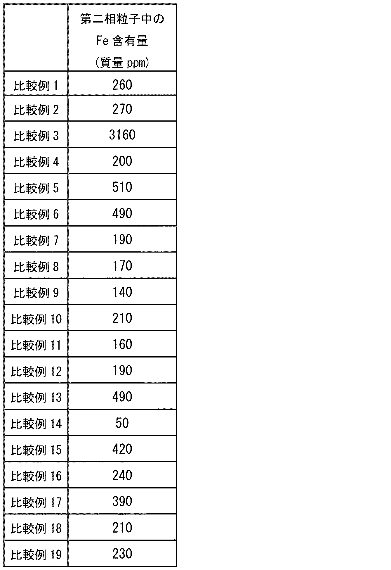
本発明者らは、国際公開2018/123933号のアルミニウム合金箔に対して上記耐塩水性評価試験を行ったところ、孔食発生部の面積率が1.5%以上となる事例を確認した。本発明者らは、鋭意研究の結果、実施例1~10のアルミニウム合金箔が、国際公開2018/123933号のアルミニウム合金箔よりも高い耐塩水性を有し、かつ国際公開2018/123933号のアルミニウム合金箔と同等程度の耐湿熱性を有することを見出した。さらに、本発明者らは、実施例1~10のアルミニウム合金箔の耐力および引張伸びが、上述した各種用途において要求される耐力および引張伸びの各仕様を満足していることを確認した。つまり、実施例1~10のアルミニウム合金箔では、耐湿熱性、耐塩水性、耐力、および引張伸びが、高次元で両立されていた。
Claims (8)
- 第1面を有するアルミニウム合金箔であって、
前記アルミニウム合金箔は、
アルミニウムと、
珪素と、
0.4質量%以上1.75質量%以下のマンガンと、
0.02質量%以上0.08質量%以下の鉄と、
0.00001質量%以上0.03質量%以下の亜鉛と、
0.00001質量%以上0.02質量%以下の銅と、
0.00001質量%以上0.01質量%以下のマグネシウムとを含み、
前記アルミニウム合金箔において、珪素および鉄の含有量の合計が0.1質量%以下であり、
前記アルミニウム合金箔において、珪素および鉄の合計質量に対するマンガンの質量の比率が7.0以上であり、
前記第1面において、円相当径が1.5μm以上である第二相粒子の面積率が0.1%以下であり、
電気比抵抗値が3.0μΩcm以上5.0μΩcm以下である、アルミニウム合金箔。 - 前記第1面において、前記第二相粒子の単位面積当たりの個数が10個/0.01228mm2以下である、請求項1に記載のアルミニウム合金箔。
- 前記第二相粒子を構成する材料は、珪素、マンガン、および鉄からなる群より選択される少なくとも1つの元素を含む、請求項2に記載のアルミニウム合金箔。
- 前記アルミニウム合金箔をフェノールに溶解させて得られた溶液を平均円相当径が1μmのフィルターでろ過した時に得られる鉄の含有量は、溶解前の前記アルミニウム合金箔の全質量に対して90質量ppm以上400質量ppm以下である、請求項3に記載のアルミニウム合金箔。
- 前記第1面に交差する方向の厚みが5μm以上300μm以下である、請求項1~4のいずれか1項に記載のアルミニウム合金箔。
- 請求項1~5のいずれか1項に記載のアルミニウム合金箔と、
前記アルミニウム合金箔の前記第1面および前記第1面とは反対側に位置する第2面の少なくともいずれかの上に配置された第1層とを備え、
前記アルミニウム合金箔および前記第1層の前記第1面と交差する方向の厚みの合計値が6μm以上301μm以下である、積層体。 - 溶解鋳造によって鋳塊を準備する工程と、
前記鋳塊を少なくとも1回冷間圧延して冷延材を形成する工程と、
前記冷延材を焼鈍する最終焼鈍工程とを備え、
前記鋳塊は、
アルミニウムと、
珪素と、
0.4質量%以上1.75質量%以下のマンガンと、
0.02質量%以上0.08質量%以下の鉄と、
0.00001質量%以上0.03質量%以下の亜鉛と、
0.00001質量%以上0.02質量%以下の銅と、
0.00001質量%以上0.01質量%以下のマグネシウムとを含み、
珪素および鉄の含有量の合計が0.1質量%以下であり、
珪素および鉄の合計質量に対するマンガンの質量の比率が7.0以上であり、
前記冷延材を形成する工程において冷間圧延される前記鋳塊の表面における円相当径が1.5μm以上である第二相粒子の面積率と、前記準備する工程において準備された前記鋳塊の表面における前記第二相粒子の面積率とは、共に0.1%以下である、アルミニウム合金箔の製造方法。 - 請求項7に記載のアルミニウム合金箔の製造方法によって製造された前記アルミニウム合金箔を準備する工程と、
前記アルミニウム合金箔の第1面および前記第1面とは反対側に位置する第2面の少なくともいずれかの上に第1層を形成する工程とを備える、積層体の製造方法。
Priority Applications (5)
| Application Number | Priority Date | Filing Date | Title |
|---|---|---|---|
| JP2021507368A JP7475328B2 (ja) | 2019-03-18 | 2020-03-17 | アルミニウム合金箔、積層体、アルミニウム合金箔の製造方法、および積層体の製造方法 |
| KR1020217033231A KR102796457B1 (ko) | 2019-03-18 | 2020-03-17 | 알루미늄 합금박, 적층체, 알루미늄 합금박의 제조 방법, 및 적층체의 제조 방법 |
| CN202080021642.3A CN113646452B (zh) | 2019-03-18 | 2020-03-17 | 铝合金箔、层叠体、铝合金箔的制造方法及层叠体的制造方法 |
| US17/439,550 US11827956B2 (en) | 2019-03-18 | 2020-03-17 | Aluminum alloy foil, laminate, method of producing aluminum alloy foil, and method of producing laminate |
| EP20774759.3A EP3943628A4 (en) | 2019-03-18 | 2020-03-17 | ALUMINUM ALLOY SHEET, LAMINATE, METHOD OF MAKING ALUMINUM ALLOY SHEET, AND METHOD OF MAKING LAMINATE |
Applications Claiming Priority (2)
| Application Number | Priority Date | Filing Date | Title |
|---|---|---|---|
| JP2019-049456 | 2019-03-18 | ||
| JP2019049456 | 2019-03-18 |
Publications (1)
| Publication Number | Publication Date |
|---|---|
| WO2020189674A1 true WO2020189674A1 (ja) | 2020-09-24 |
Family
ID=72520901
Family Applications (1)
| Application Number | Title | Priority Date | Filing Date |
|---|---|---|---|
| PCT/JP2020/011687 Ceased WO2020189674A1 (ja) | 2019-03-18 | 2020-03-17 | アルミニウム合金箔、積層体、アルミニウム合金箔の製造方法、および積層体の製造方法 |
Country Status (6)
| Country | Link |
|---|---|
| US (1) | US11827956B2 (ja) |
| EP (1) | EP3943628A4 (ja) |
| JP (1) | JP7475328B2 (ja) |
| KR (1) | KR102796457B1 (ja) |
| CN (1) | CN113646452B (ja) |
| WO (1) | WO2020189674A1 (ja) |
Cited By (1)
| Publication number | Priority date | Publication date | Assignee | Title |
|---|---|---|---|---|
| WO2024079948A1 (ja) * | 2022-10-13 | 2024-04-18 | 東洋アルミニウム株式会社 | アルミニウム箔及びその製造方法 |
Families Citing this family (2)
| Publication number | Priority date | Publication date | Assignee | Title |
|---|---|---|---|---|
| RU2639203C2 (ru) * | 2016-05-31 | 2017-12-20 | Общество с ограниченной ответственностью "Объединенная Компания РУСАЛ Инженерно-технологический центр" | Способ совмещенного непрерывного литья, прокатки и прессования металлической заготовки и устройство для его реализации |
| US12139777B2 (en) * | 2019-03-18 | 2024-11-12 | Toyo Aluminium Kabushiki Kaisha | Aluminum alloy foil, laminate, method of producing aluminum alloy foil, and method of producing laminate |
Citations (3)
| Publication number | Priority date | Publication date | Assignee | Title |
|---|---|---|---|---|
| JPH06278243A (ja) * | 1993-03-26 | 1994-10-04 | Nippon Steel Corp | 成形加工性、耐食性および焼付硬化性に優れたアルミニウム合金合わせ板 |
| WO2016125608A1 (ja) * | 2015-02-03 | 2016-08-11 | 東洋アルミニウム株式会社 | アルミニウム箔、電子デバイス、ロールツーロール用アルミニウム箔、およびアルミニウム箔の製造方法 |
| WO2018123933A1 (ja) | 2016-12-27 | 2018-07-05 | 東洋アルミニウム株式会社 | アルミニウム合金箔及びその積層体並びにそれらの製造方法 |
Family Cites Families (11)
| Publication number | Priority date | Publication date | Assignee | Title |
|---|---|---|---|---|
| JP3161141B2 (ja) * | 1993-03-02 | 2001-04-25 | 日本軽金属株式会社 | アルミニウム合金薄板の製造方法 |
| JP4419181B2 (ja) * | 2000-10-20 | 2010-02-24 | 日本製箔株式会社 | 電解コンデンサ陰極用アルミニウム合金箔の製造方法 |
| JP4576001B2 (ja) * | 2000-11-22 | 2010-11-04 | 日本製箔株式会社 | 電解コンデンサ電極用アルミニウム箔 |
| CN100453672C (zh) | 2007-06-11 | 2009-01-21 | 江苏常铝铝业股份有限公司 | 包装用铝合金箔材及其制造方法 |
| JP5116403B2 (ja) | 2007-08-08 | 2013-01-09 | 東洋アルミニウム株式会社 | アルミニウム合金ならびにそれを用いた包装材および電気電子構造部材 |
| CN101289720B (zh) * | 2008-06-17 | 2010-12-22 | 上海大屯能源股份有限公司 | 空调箔及其制备方法 |
| CN101519760B (zh) | 2009-04-09 | 2010-09-15 | 登电集团铝加工有限公司 | 一种3003牌号阴极铝箔的制造方法 |
| JP2011009392A (ja) * | 2009-06-25 | 2011-01-13 | Toyo Aluminium Kk | 太陽電池モジュール用裏面保護シート |
| WO2014021170A1 (ja) | 2012-08-01 | 2014-02-06 | 古河スカイ株式会社 | アルミニウム合金箔及びその製造方法 |
| JP5897430B2 (ja) | 2012-08-30 | 2016-03-30 | 株式会社Uacj | ラミネート後の成形性に優れたアルミニウム合金箔とその製造方法、および該アルミニウム合金箔を用いたラミネート箔 |
| KR102359934B1 (ko) | 2017-05-10 | 2022-02-07 | 현대자동차 주식회사 | 차량용 자동변속기의 유성기어트레인 |
-
2020
- 2020-03-17 EP EP20774759.3A patent/EP3943628A4/en active Pending
- 2020-03-17 WO PCT/JP2020/011687 patent/WO2020189674A1/ja not_active Ceased
- 2020-03-17 KR KR1020217033231A patent/KR102796457B1/ko active Active
- 2020-03-17 CN CN202080021642.3A patent/CN113646452B/zh active Active
- 2020-03-17 US US17/439,550 patent/US11827956B2/en active Active
- 2020-03-17 JP JP2021507368A patent/JP7475328B2/ja active Active
Patent Citations (3)
| Publication number | Priority date | Publication date | Assignee | Title |
|---|---|---|---|---|
| JPH06278243A (ja) * | 1993-03-26 | 1994-10-04 | Nippon Steel Corp | 成形加工性、耐食性および焼付硬化性に優れたアルミニウム合金合わせ板 |
| WO2016125608A1 (ja) * | 2015-02-03 | 2016-08-11 | 東洋アルミニウム株式会社 | アルミニウム箔、電子デバイス、ロールツーロール用アルミニウム箔、およびアルミニウム箔の製造方法 |
| WO2018123933A1 (ja) | 2016-12-27 | 2018-07-05 | 東洋アルミニウム株式会社 | アルミニウム合金箔及びその積層体並びにそれらの製造方法 |
Non-Patent Citations (1)
| Title |
|---|
| See also references of EP3943628A4 |
Cited By (1)
| Publication number | Priority date | Publication date | Assignee | Title |
|---|---|---|---|---|
| WO2024079948A1 (ja) * | 2022-10-13 | 2024-04-18 | 東洋アルミニウム株式会社 | アルミニウム箔及びその製造方法 |
Also Published As
| Publication number | Publication date |
|---|---|
| JP7475328B2 (ja) | 2024-04-26 |
| CN113646452A (zh) | 2021-11-12 |
| US11827956B2 (en) | 2023-11-28 |
| EP3943628A1 (en) | 2022-01-26 |
| US20220186344A1 (en) | 2022-06-16 |
| KR20210137554A (ko) | 2021-11-17 |
| JPWO2020189674A1 (ja) | 2020-09-24 |
| KR102796457B1 (ko) | 2025-04-15 |
| EP3943628A4 (en) | 2022-12-14 |
| CN113646452B (zh) | 2022-12-02 |
Similar Documents
| Publication | Publication Date | Title |
|---|---|---|
| JP4716520B2 (ja) | 圧延銅箔 | |
| JP5944862B2 (ja) | 陽極酸化処理後の表面品質に優れたアルミニウム合金板およびその製造方法 | |
| KR101508099B1 (ko) | 전자파 실드용 금속박, 전자파 실드재 및 실드 케이블 | |
| JP7475328B2 (ja) | アルミニウム合金箔、積層体、アルミニウム合金箔の製造方法、および積層体の製造方法 | |
| JP5671091B2 (ja) | 陽極酸化処理後の表面品質に優れたアルミニウム合金板およびその製造方法 | |
| JP2008280565A (ja) | マグネシウム合金およびその製造方法 | |
| WO2022196489A1 (ja) | アルミニウム合金箔、アルミニウム積層体、及びアルミニウム合金箔の製造方法 | |
| JP7317504B2 (ja) | アルミニウム合金箔及びその積層体並びにそれらの製造方法 | |
| JP4014229B2 (ja) | アルミニウム合金製品 | |
| JP7519345B2 (ja) | アルミニウム合金箔、積層体、アルミニウム合金箔の製造方法、および積層体の製造方法 | |
| JP2020147807A (ja) | アルミニウム合金箔、積層体、アルミニウム合金箔の製造方法、および積層体の製造方法 | |
| JP2011157607A (ja) | アルミニウム合金製導電体及びその製造方法 | |
| JP2020147806A (ja) | アルミニウム合金箔、積層体、アルミニウム合金箔の製造方法、および積層体の製造方法 | |
| JP5522000B2 (ja) | マグネシウム合金部材 | |
| EP2511391A1 (en) | Magnesium alloy member | |
| WO2024116659A1 (ja) | アルミニウム合金箔、アルミニウム合金箔を用いた積層体およびそれらの製造方法 | |
| Kim et al. | Mechanical Properties of Al/Al-Mg/Al Clad Sheets Fabricated by Roll Bonding Process |
Legal Events
| Date | Code | Title | Description |
|---|---|---|---|
| 121 | Ep: the epo has been informed by wipo that ep was designated in this application |
Ref document number: 20774759 Country of ref document: EP Kind code of ref document: A1 |
|
| ENP | Entry into the national phase |
Ref document number: 2021507368 Country of ref document: JP Kind code of ref document: A |
|
| NENP | Non-entry into the national phase |
Ref country code: DE |
|
| ENP | Entry into the national phase |
Ref document number: 20217033231 Country of ref document: KR Kind code of ref document: A |
|
| ENP | Entry into the national phase |
Ref document number: 2020774759 Country of ref document: EP Effective date: 20211018 |