WO2020189698A1 - 刃先交換式ドリル、切削インサートおよびドリル本体 - Google Patents
刃先交換式ドリル、切削インサートおよびドリル本体 Download PDFInfo
- Publication number
- WO2020189698A1 WO2020189698A1 PCT/JP2020/011874 JP2020011874W WO2020189698A1 WO 2020189698 A1 WO2020189698 A1 WO 2020189698A1 JP 2020011874 W JP2020011874 W JP 2020011874W WO 2020189698 A1 WO2020189698 A1 WO 2020189698A1
- Authority
- WO
- WIPO (PCT)
- Prior art keywords
- drill
- insert
- tip
- mounting seat
- chip discharge
- Prior art date
- Legal status (The legal status is an assumption and is not a legal conclusion. Google has not performed a legal analysis and makes no representation as to the accuracy of the status listed.)
- Ceased
Links
Images


Classifications
-
- B—PERFORMING OPERATIONS; TRANSPORTING
- B23—MACHINE TOOLS; METAL-WORKING NOT OTHERWISE PROVIDED FOR
- B23B—TURNING; BORING
- B23B51/00—Tools for drilling machines
- B23B51/0002—Drills with connected cutting heads, e.g. with non-exchangeable cutting heads; Drills with a single insert extending across the rotational axis and having at least two radially extending cutting edges in the working position
- B23B51/0003—Drills with connected cutting heads, e.g. with non-exchangeable cutting heads; Drills with a single insert extending across the rotational axis and having at least two radially extending cutting edges in the working position with exchangeable heads or inserts
- B23B51/0004—Drills with connected cutting heads, e.g. with non-exchangeable cutting heads; Drills with a single insert extending across the rotational axis and having at least two radially extending cutting edges in the working position with exchangeable heads or inserts with cutting heads or inserts attached by screw means
-
- B—PERFORMING OPERATIONS; TRANSPORTING
- B23—MACHINE TOOLS; METAL-WORKING NOT OTHERWISE PROVIDED FOR
- B23B—TURNING; BORING
- B23B51/00—Tools for drilling machines
- B23B51/02—Twist drills
Definitions
- an insert mounting seat is formed at the tip of a drill body that is rotated around an axis, and a cutting insert is detachably attached to the insert mounting seat.
- the present invention relates to a cutting insert that is detachably attached to an insert mounting seat, and a drill body of such a replaceable cutting edge drill.
- a split surface extending perpendicular to the axis and a torque transmission surface adjacent to the split surface are formed on the insert mounting seat of the drill body to form a cutting insert. Is formed with a split surface extending perpendicular to the axis and a torque receiving surface extending from the split surface toward the tip flank surface and adjacent to the tip flank surface.
- This cutting insert is detachably attached to the insert mounting seat by a fastening screw.
- An object of the present invention is to prevent sludge from entering the contact portion between the cutting insert and the insert mounting seat from the tip side of the drill body, thereby preventing the drill life from being shortened.
- the replaceable cutting edge drill has a drill body in which an insert mounting seat is formed at a tip portion and is rotated around an axis, and a cutting insert detachably attached to the insert mounting seat.
- a body chip discharge groove that opens at the tip surface of the drill body and extends to the rear end side of the drill body is formed, and the cutting insert has a relief at the tip of the cutting insert.
- An insert chip discharge groove is formed that opens on the surface and communicates with the main body chip discharge groove.
- a cutting edge is formed at the intersection ridge between the wall surface of the insert chip discharge groove facing the drill rotation direction and the tip flank surface, and the insert mounting seat has a bottom surface facing the tip end side of the drill body and the bottom surface.
- a wall surface extending toward the tip end side of the drill body and facing the drill rotation direction and a screw hole opening in the bottom surface are formed.
- the cutting insert includes a seating surface that faces the rear end side of the drill body and sits on the bottom surface, and a contact surface that faces the side opposite to the drill rotation direction and abuts on the wall surface from the drill rotation direction.
- a convex portion protruding in the direction opposite to the drill rotation direction and a mounting hole penetrating from the tip flank surface to the seating surface are formed.
- the cutting insert is attached to the insert mounting seat by screwing a clamp screw inserted into the mounting hole into the screw hole.
- the tip of the contact portion between the contact surface and the wall surface is drilled on the tip side of the contact surface. It is covered by a protrusion that protrudes in the direction opposite to the direction of rotation. That is, the tip of the contact interface between the contact surface and the wall surface is closed by the convex portion protruding from the contact surface on the side opposite to the drill rotation direction. As a result, it is possible to prevent foreign matter such as sludge from entering from the tip of the contact portion between the contact surface and the wall surface.
- the cutting insert of the present invention is a cutting insert that can be detachably attached to the insert mounting seat of the drill body in the drill body of the above-mentioned replaceable cutting edge drill, and is opened to the tip flank surface of the insert body.
- An insert chip discharge groove communicating with the main body chip discharge groove is formed, and a cutting edge is formed at an intersection ridge between the wall surface of the insert chip discharge groove facing the drill rotation direction and the tip flank surface, and after the drill body.
- a seating surface that faces the end side and is seated on the bottom surface of the insert mounting seat, and a contact surface that faces the side opposite to the drill rotation direction and is brought into contact with the wall surface of the insert mounting seat from the drill rotation direction.
- On the tip end side of the contact surface a convex portion protruding from the contact surface in the direction opposite to the drill rotation direction and a mounting hole penetrating from the tip relief surface to the seating surface are formed.
- the drill body of the present invention is a drill body in the above-mentioned replaceable cutting edge drill, and has an insert mounting seat formed at the tip portion, and a main body chip that opens to the tip surface and extends to the rear end side on the outer periphery of the tip portion.
- a discharge groove is formed, and the insert mounting seat has a bottom surface facing the tip side, a wall surface extending toward the tip side with respect to the bottom surface and facing the drill rotation direction, and an opening in the bottom surface to screw the clamp screw.
- a screw hole is formed.
- the contact is brought into contact with the wall surface (torque transmission surface) of the insert mounting seat from the direction of rotation of the drill facing the side opposite to the direction of rotation of the cutting insert.
- a convex portion is formed that protrudes from the contact surface to the side opposite to the drill rotation direction, and the contact surface of the cutting insert is not adjacent to the tip flank surface and is not suitable. It is said to be continuous.
- the convex portion is arranged on the tip end side of the contact portion between the contact surface and the wall surface, and this contact portion is covered by the convex portion. Therefore, the contact portion between the contact surface of these cutting inserts and the wall surface of the insert mounting seat is not exposed to the tip of the replaceable cutting edge drill.
- a shaft portion is formed on the split surface of the cutting insert, and a hole portion is formed on the split surface of the insert mounting seat, and the shaft portion is formed in this hole portion.
- this hole is a circular hole with a continuous inner peripheral surface, and this hole is a blind hole that does not penetrate the drill body, and the difference between the inner diameter of the hole and the outer diameter of the shaft of the cutting insert is If it is small, the air in the hole is compressed when the shaft is inserted, and the pressure exerts a force to push out the cutting insert.
- a shaft portion centered on the axis is formed on one of the seating surface of the cutting insert and the bottom surface of the insert mounting seat, and the other shaft is formed. It is desirable that a hole into which the portion can be fitted is formed around the axis, and the hole is opened in the main body chip discharge groove or the insert chip discharge groove.
- the wall surface and the contact surface so that the outer peripheral side of the drill body has a wider width in the axial direction than the inner peripheral side, the largest cutting load acts during drilling.
- a large contact area of the contact surface with the wall surface on the outer peripheral side of the drill body can be secured. Therefore, the stress acting on the outermost circumference of the drill body of the insert mounting seat can be reduced.
- a recess recessed with respect to the bottom surface and the wall surface is formed at a corner portion where the bottom surface and the wall surface intersect from the chip discharge groove of the main body to the outer peripheral surface of the drill body. It is possible to prevent the intersecting ridge line portion between the seating surface and the contact surface of the cutting insert from interfering with the corner portion where the bottom surface and the wall surface of the insert mounting seat intersect and impairing the mounting stability of the cutting insert.
- the cross-sectional area of the recess is set so that the opening on the outer peripheral surface side of the drill body is larger than the opening on the chip discharge groove side of the main body, as described above.
- stress concentration in the recesses can be relaxed.
- the cross section of the opening on the chip discharge groove side of the main body is small, the rigidity of the convex wall portion of the drill body on which the wall surface is formed is not impaired.
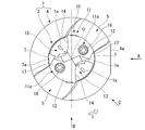
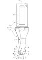
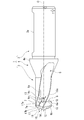
- FIG. 1 It is a perspective view which shows the 1st Embodiment of the cutting edge exchange type drill in this invention. It is a perspective view which looked at the embodiment shown in FIG. 1 from another direction. It is a front view of the embodiment shown in FIG. It is a side view of the arrow line A direction view in FIG. 3 of the embodiment shown in FIG. It is a side view of the arrow line B direction view in FIG. 3 of the embodiment shown in FIG. It is a side view of the arrow C direction view in FIG. 3 of the embodiment shown in FIG. It is an exploded view of the embodiment shown in FIG. It is a front view which shows the 1st Embodiment of the drill body in this invention. It is a side view of the arrow A direction view of the embodiment shown in FIG.
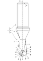
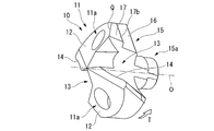
- FIG. 10 It is a perspective view which shows 1st Embodiment of the cutting insert in this invention. It is a perspective view which looked at the embodiment shown in FIG. 10 from another direction. It is a front view of the embodiment shown in FIG. It is a side view of the arrow line A direction view in FIG. 12 of the embodiment shown in FIG. It is a side view of the arrow line B direction view in FIG. 12 of the embodiment shown in FIG. It is a perspective view which shows the 2nd Embodiment of the cutting edge exchange type drill in this invention. It is a perspective view which looked at the embodiment shown in FIG. 15 from another direction. It is a front view of the embodiment shown in FIG. It is a side view of the arrow line A direction view in FIG. 16 of the embodiment shown in FIG.
- FIG. 16 It is a side view of the arrow line B direction view in FIG. 16 of the embodiment shown in FIG. It is a side view of the arrow C direction view in FIG. 16 of the embodiment shown in FIG. It is an exploded view of the embodiment shown in FIG. It is a front view which shows the 2nd Embodiment of the drill body in this invention. It is a side view of the arrow A direction view of the embodiment shown in FIG. It is a side view of the arrow line B direction view of the embodiment shown in FIG. It is a perspective view which shows the 2nd Embodiment of the cutting insert in this invention. It is a perspective view which looked at the embodiment shown in FIG. 25 from another direction. It is a front view of the embodiment shown in FIG.
- FIG. 5 is an exploded cross-sectional view of the cutting insert and the drill body of the embodiment shown in FIG. 15 along the axis.
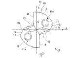
- FIGS. 10 to 14 show a cutting insert detachably attached to the drill body. 1 Embodiment is shown.
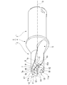
- the drill body 1 is formed of a metal material such as steel in a multi-stage columnar shape centered on the axis O.
- the rear end portion of the drill body 1 (the right portion in FIGS. 1, 4 to 7, and 9) is a large-diameter shank portion 2, and the tip portion (FIG. 1, FIG. 2, FIGS. 4 to 7).
- the left side portion in FIG. 9) is a cutting edge portion 3 to which the insert body 11 of the cutting insert 10 is detachably attached.
- the "tip side” means the front end side of the drill body 1
- the "rear end side” means the rear end side of the drill body 1.
- the cutting edge portion 3 has a smaller diameter than the shank portion 2, and the diameter between the shank portion 2 and the cutting edge portion 3 is reduced by one step from the shank portion 2 toward the tip side, and then the diameter of the cutting edge portion 3 is reduced.
- a collar portion 4 having the same diameter as 3 is formed.
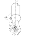
- the shank portion 2 of the drill body 1 is gripped by the spindle of the machine tool, and the cutting insert 10 is sent out to the tip side in the O direction of the axis while being rotated in the rotation direction T of the drill around the axis O. Drilling is performed in the work material with the cutting edge of.
- a flat surface 2a extending parallel to the axis O is formed on the outer peripheral surface of the shank portion 2 with a gap between the front end and the rear end of the shank portion 2, and the diameter is expanded with respect to the shank portion 2 of the flange portion 4.
- a flat surface 4a parallel to the flat surface 2a is also formed in the portion.
- a plurality of main body chip discharge grooves 5 are formed on the outer peripheral portion of the drill main body 1 at intervals in the circumferential direction from the tip of the cutting edge portion 3 to the front of the rear end of the flange portion 4.
- two main body chip discharge grooves 5 are formed at equal intervals in the circumferential direction, and these main body chip discharge grooves 5 are aligned with the drill rotation direction T around the axis O toward the rear end side of the drill body 1.
- An insert mounting seat 6 is formed at the tip of the cutting edge portion 3. As shown in FIGS. 5, 7, and 8, the insert mounting seat 6 is formed by cutting out the central portion of the tip of the cutting edge portion 3 in a rectangular shape when viewed from a direction perpendicular to the axis O. Has been done. As shown in FIG. 8, the notched region extends in the radial direction with respect to the axis O and reaches from one main body chip discharge groove 5 to the other main body chip discharge groove 5. The width of the notched rectangular region reaches from the wall surface of each of the main body chip discharge grooves 5 facing the drill rotation direction T to the wall surface facing the side opposite to the drill rotation direction T. The notched region is flat because the depth in the axis O direction is smaller than the width in the radial direction when viewed from the direction perpendicular to the axis O.
- the insert mounting seat 6 has a bottom surface 6a extending in a direction perpendicular to the axis O and facing the tip end side of the drill body 1, and an axis perpendicular to the bottom surface 6a from both sides of the bottom surface 6a. It has two wall surfaces 6b that extend parallel to O and face the drill rotation direction T. The wall surfaces 6b face each other and are parallel to each other. Each of these wall surfaces 6b has a rectangular shape having a longitudinal direction in the radial direction with respect to the axis O in the present embodiment.
- the hole portion 6c having a circular inner cross section with a constant inner diameter centered on the axis O is formed so as to extend toward the rear end side of the drill body 1 so as to open at the central portion of the bottom surface 6a. ..
- the inner diameter of the hole 6c is larger than the diameter of the virtual circle inscribed in the bottom surface of the main body chip discharge groove 5 facing the outer peripheral side of the drill main body 1 in the cross section orthogonal to the axis O. Therefore, both sides of the hole 6c are rectangularly opened at the bottom surface of each main body chip discharge groove 5, and the bottom surface 6a of the insert mounting seat 6 is 180 ° rotationally symmetric with respect to the axis O by the hole 6c. It is divided into two parts.
- the hole portion 6c is a blind hole having a bottom surface facing the tip end side of the drill body 1.
- the bottom surface 6a divided into two by the hole 6c is formed with a screw hole 6d having a center at the same distance from the axis O at a distance from the hole 6c.
- a coolant hole 1a is formed in the drill body 1 from the rear end surface of the shank portion 2 toward the tip side along the axis O, and the coolant hole 1a is branched into two in front of the insert mounting seat 6, and each of them is formed.
- the tip is opened on the wall surface of the main body chip discharge groove 5 facing the side opposite to the drill rotation direction T.
- the wall surface 6b of the insert mounting seat 6 opposite to the drill rotation direction T On the side of the wall surface 6b of the insert mounting seat 6 opposite to the drill rotation direction T, the wall surface 6b, the outer peripheral surface of the cutting edge portion 3, and the wall surface of the main body chip discharge groove 5 facing the opposite side of the drill rotation direction T.
- the convex wall portion 7 surrounded by the above is left, and the tip surface 7a of the convex wall portion 7 is a flat surface perpendicular to the axis O.
- a recess 6e having a constant inner diameter and a circular cross section and being recessed with respect to the bottom surface 6a and the wall surface 6b It is formed as a relief part.
- the recess 6e is for avoiding interference between the bottom surface 6a and the wall surface 6b of the insert mounting seat 6 and the cutting insert 10. Further, the insert mounting seat 6 and the two main body chip discharge grooves 5 each have a 180 ° rotationally symmetric shape with respect to the axis O.
- the cutting insert 10 detachably attached to the insert mounting seat 6 is an insert body 11 formed of a hard material such as cemented carbide having a hardness higher than that of the drill body 1. It has.
- the insert body 11 has a shape that is 180 ° rotationally symmetric with respect to the axis O of the drill body 1 when it is mounted on the insert mounting seat 6.
- the insert body 11 has a tip flank surface 12 facing the tip end side of the drill body 1 and an opening in the tip flank surface 12 so as to communicate with the two main body chip discharge grooves 5 in a state of being mounted on the insert mounting seat 6.
- the insert chip discharge groove 13 is formed, and the cutting edge 14 is formed at the intersecting ridge line portion between the wall surface of the insert chip discharge groove 13 facing the drill rotation direction T and the tip flank surface 12.
- the tip flank surface 12 is inclined so as to face the rear end side of the drill body 1 toward the side opposite to the drill rotation direction T and the outer peripheral side of the drill body 1, whereby the clearance angle and the tip angle of the cutting edge 14 are increased. Is given.
- the rear end surface of the insert body 11 is a flat surface perpendicular to the axis O as shown in FIGS. 13 and 14, and the insert is inserted facing the rear end side of the drill body 1. It is a seating surface 15 that sits on the bottom surface 6a of the mounting seat 6.
- a multi-stage columnar shaft portion 15a having a large diameter at the tip and a slightly small diameter at the rear end is formed so as to project toward the rear end side with the axis O as the center.
- the outer diameter of the tip of the shaft portion 15a is set to a size that can be fitted into the hole portion 6c of the insert mounting seat 6.
- the insert mounting seat faces the side opposite to the drill rotation direction T from the drill rotation direction T.
- Contact surfaces 16 that come into contact with the wall surface 6b of No. 6 are formed. These contact surfaces 16 are formed so as to intersect the seating surface 15 perpendicularly, to be parallel to the axis O, and to extend parallel to each other.
- the contact surface 16 of the present embodiment has a rectangular shape having a longitudinal direction in the radial direction with respect to the axis O.
- the insert body 11 is formed with two mounting holes 11a penetrating from the tip flank surface 12 to the seating surface 15 at intervals from the shaft portion 15a. These mounting holes 11a are arranged so as to be coaxial with the two screw holes 6d of the insert mounting seat 6 in a state where the contact surface 16 is in contact with the wall surface 6b of the insert mounting seat 6. As shown in FIG. 12, the inner diameter of the mounting hole 11a gradually decreases from the opening on the tip flank surface 12 side toward the seating surface 15, and is constant on the seating surface 15 side.
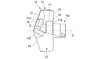
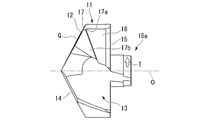
- the insert body 11 of the cutting insert 10 is formed with a convex portion 17 protruding from the contact surface 16 on the tip side of the contact surface 16 in the direction opposite to the drill rotation direction T.
- the shaft portion 15a of the insert body 11 is fitted into the hole portion 6c of the insert mounting seat 6, the seating surface 15 is brought into close contact with the bottom surface 6a, and the contact surface 16 is brought into contact with the wall surface 6b.
- the contact surface 16 and the wall surface 6b are arranged on the tip end side of the contact portion P with almost no gap to cover the tip end portion of the contact portion P.
- the contact portion P between the contact surface 16 and the wall surface 6b is closed by the convex portion 17 with almost no gap, and foreign matter is prevented from entering from the tip.
- the rear end surface 17a of the convex portion 17 facing the rear end side of the drill body 1 is perpendicular to the axis O in a state where the seating surface 15 of the insert body 11 is in close contact with the bottom surface 6a of the insert mounting seat 6 as described above.
- the tip of the contact portion P between the contact surface 16 and the wall surface 6b is covered with the convex portion 17.
- the side surface 17b of the convex portion 17 facing the side opposite to the drill rotation direction T extends parallel to the contact surface 16 and is adjacent to the tip escape surface 12, that is, parallel to the axis O and perpendicular to the rear end surface 17a. It extends to and intersects the tip flank surface 12 of the insert body 11 at an angle at the crossing ridge line Q.
- the convex portion 17 of this embodiment does not cover all of the tip surface 7a of the convex wall portion 7 of the drill body 1, and the tip surface 7a is located on the side surface 17b opposite to the drill rotation direction T. It is exposed.
- the convex portion 17 may cover all of the tip surface 7a of the convex wall portion 7 of the drill body 1.
- the shaft portion 15a is fitted into the hole portion 6c of the insert mounting seat 6, the seating surface 15 is brought into close contact with the bottom surface 6a, and the contact surface 16 is attached to the wall surface 6b.
- the clamp screw 18 inserted into the mounting hole 11a from the tip side of the drill body 1 is screwed into the screw hole 6d to be detachably attached to the insert mounting seat 6.
- the cutting blade 14 of the insert body 11 in the cutting insert 10 ejects coolant such as a cutting fluid from the coolant hole 1a formed in the drill body 1.
- the work material is cut and a hole is drilled in the work material.
- a convex portion 17 is formed on the tip side of the contact surface 16 which is brought into contact with the wall surface 6b of the insert mounting seat 6 in the insert body 11 so as to protrude from the contact surface 16 on the side opposite to the drill rotation direction T.
- the convex portion 17 is arranged on the tip end side of the contact portion P between the contact surface 16 and the wall surface 6b to cover the tip portion of the contact portion P, so that the tip portion of the contact portion P is a convex portion.
- the contact portion P is not exposed to the tip of the replaceable cutting edge drill because it is blocked by 17.
- the convex portion 17 is formed so that the side surface 17b adjacent to the tip flank surface 12 facing the side opposite to the drill rotation direction T intersects the tip flank surface 12 at an angle at the cross ridge line Q. There is. Therefore, when the cutting edge 14 is worn and the sharpness becomes dull, the tip flank surface 12 is re-polished and a new cutting edge 14 is formed at the intersecting ridge line portion of the insert chip discharge groove 13 with the wall surface facing the drill rotation direction T. By checking the width of the side surface 17b between the crossing ridge line Q and the seating surface 15 in the axis O direction, it is possible to visually confirm whether or not re-polishing is possible. Therefore, it is possible to avoid a situation in which the convex portion 17 becomes too thin and the convex wall portion 7 of the drill body 1 is worn.
- a shaft portion 15a centered on the axis O is formed on the seating surface 15 of the insert body 11 of the cutting insert 10, and a hole into which the shaft portion 15a can be fitted is formed in the bottom surface 6a of the insert mounting seat 6.
- the portion 6c is formed around the axis O. Therefore, the cutting insert 10 can be attached to the center of the axis O of the drill body 1 with high accuracy, and the runout accuracy of the cutting edge 14 can be ensured.
- the hole 6c is opened in the chip discharge groove 5 of the main body 1 of the drill body 1, air in the hole 6c can be discharged when the shaft portion 15a is fitted into the hole 6c, and the hole 6c can be discharged. It is possible to avoid the air inside being compressed. Therefore, the force that pushes the insert body 11 toward the tip end side of the drill body 1 does not act due to the pressure of the compressed air. Therefore, according to the present embodiment, the cutting insert 10 is firmly and stably inserted. Can be attached to 6.
- a shaft portion 15a centered on the axis O is formed on the seating surface 15 of the insert body 11, and a hole into which the shaft portion 15a can be fitted is formed in the bottom surface 6a of the insert mounting seat 6.
- the portion 6c is formed centered on the axis O.
- a hole portion centered on the axis O is formed on the seating surface 15 of the insert body 11, and the bottom surface 6a of the insert mounting seat 6 is formed.
- a shaft portion that can be fitted into the hole portion may be formed around the axis O, and the hole portion may be opened in the insert chip discharge groove 13.
- a coolant hole 1a is formed in the drill body 1 from the rear end surface of the shank portion 2 toward the tip side along the axis O, and the coolant hole 1a is 2 in front of the insert mounting seat 6. It is branched into two and opened on the wall surface of the main body chip discharge groove 5 facing the side opposite to the drill rotation direction T. Instead, two coolant holes are provided from the rear end surface of the shank portion 2.
- a wall surface formed between the main body chip discharge grooves 5 toward the tip end side of the drill main body 1 and having these coolant holes facing the side opposite to the drill rotation direction T of the main body chip discharge groove 5 in front of the insert mounting seat 6. May be opened to.
- the insert main body 11 has two mounting holes 11a penetrating from the tip flank surface 12 to the seating surface 15, and the contact surface 16 is brought into contact with the wall surface 6b of the insert mounting seat 6. It is arranged so as to be coaxial with the two screw holes 6d of the insert mounting seat 6, but instead, it is slightly opposite to the contact surface 16 with respect to the two screw holes 6d of the insert mounting seat 6. It may be arranged eccentrically on the side.
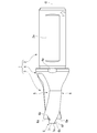
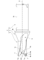
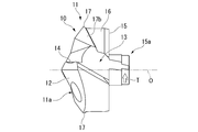
- FIGS. 15 to 20 show a second embodiment of the cutting edge replaceable drill in the present invention
- FIGS. 21 and 31 show an exploded view of the cutting edge replaceable drill in the second embodiment
- 22 to 24 show a second embodiment of the drill body of the present invention of the replaceable cutting edge drill of the second embodiment
- FIGS. 25 to 30 show a cutting insert 10 detachably attached to the drill body.
- the second embodiment of is shown.
- the same reference numerals are given to the parts common to those of the first embodiment shown in FIGS. 1 to 14, which cannot be described later. Regarding the matters, the explanation in the first embodiment is incorporated.
- the wall surface 6b of the insert mounting seat 6 facing the drill rotation direction T and the contact surface 16 of the insert body 11 of the cutting insert 10 to be brought into contact with the wall surface 6b are rectangular and have a rectangular shape.
- the width of the 6b and the contact surface 16 in the axial direction O was constant in the radial direction with respect to the axis O, whereas in the second embodiment, the wall surface 6b and the contact surface 16 are the drill body 1.
- the width of the outer peripheral side in the axis O direction is larger than that of the inner peripheral side.
- the width of the wall surface 6b and the contact surface 16 in the axis O direction is from the inner peripheral side to the outer peripheral side of the drill body 1. Therefore, the wall surface 6b and the contact surface 16 are formed in a substantially trapezoidal shape.
- the recess 6e as a relief portion formed at the corner where the bottom surface 6a and the wall surface 6b of the insert mounting seat 6 intersect has a circular inner diameter, and therefore a constant cross section.
- the cross-sectional area of the recess 6e is formed so that the opening on the outer peripheral surface side of the drill body 1 is larger than the opening on the side of the chip discharge groove 5 of the main body. Has been done.
- the recess 6e has a portion having a circular cross section in order from the opening on the main body chip discharge groove 5 side toward the opening on the outer peripheral surface side of the drill main body 1.
- the cross section having a cross-sectional area larger than that of the circular portion by two steps is formed by a concave curved portion, and the length of the portion of the recess 6e having a circular cross section that opens to the main body chip discharge groove 5 side is It has been the longest. Further, as shown in FIGS.
- the intersecting ridge line portion between the wall surface 6b of the insert mounting seat 6 and the inner peripheral surface of the main body chip discharge groove 5 is chamfered, and the wall surface 6b and the main body are chamfered.
- a chamfered portion 6f that intersects the inner peripheral surface of the chip discharge groove 5 is formed.
- the replaceable cutting edge drill, the cutting insert 10 and the drill body 1 of the second embodiment the same effect as that of the first embodiment can be obtained, of course, and first, the wall surface 6b of the insert mounting seat 6 and the cutting insert 10 are contacted. Since the outer peripheral side of the drill body 1 has a wider width in the axis O direction than the inner peripheral side of the contact surface 16, the wall surface 6b on the outer peripheral side of the drill body 1 on which the largest cutting load acts during drilling. A large contact area of the contact surface 16 can be secured.
- the stress acting on the outermost circumference of the drill body 1 of the insert mounting seat 6 can be reduced, and the cutting insert 10 can be stably held even with respect to the cutting load during drilling.
- High-precision drilling can be performed.
- the width of the wall surface 6b and the contact surface 16 in the axis O direction is formed so as to gradually widen from the inner peripheral side to the outer peripheral side of the drill body 1. A larger contact area of the contact surface 16 with 6b can be secured.
- the cross-sectional area of the recess 6e formed so as to be recessed with respect to the bottom surface 6a and the wall surface 6b as a relief portion at the corner where the bottom surface 6a and the wall surface 6b of the insert mounting seat 6 intersect is the main body.
- the opening on the outer peripheral surface side of the drill body 1 is formed to be larger than the opening on the chip discharge groove 5 side. Therefore, as described above, the stress concentration in the recess 6e can be relaxed on the outer peripheral surface side of the drill body 1 on which the largest cutting load acts during drilling.
- the opening on the main body chip discharge groove 5 side has a small cross section, the rigidity of the convex wall portion 7 of the drill main body 1 on which the wall surface 6b is formed is not impaired, and the stable cutting insert 10 is held. Is not disturbed.
- the recess 6e is formed so that the cross-sectional area is gradually increased, and the step length of the portion having a circular cross section on the main body chip discharge groove 5 side is the longest. , The rigidity of the convex wall portion 7 can be maintained more reliably.
- the cross-sectional shape of the recess 6e may be a circular concave curve or a non-circular concave curve.
- the intersecting ridge line portion between the wall surface 6b of the insert mounting seat 6 and the inner peripheral surface of the main body chip discharge groove 5 is chamfered to form the inner peripheral surface of the wall surface 6b and the main body chip discharge groove 5.
- the hole 6c that opens in the bottom surface 6a of the insert mounting seat 6 of the drill body 1 has a large cross section with a circular cross section centered on the axis O having a constant inner diameter at the tip end side and a long length in the axis O direction.
- the diameter portion is 6c1
- the rear end side portion has a circular cross section centered on the axis O having a constant inner diameter slightly smaller than the large diameter portion 6c1 and the length in the axis O direction is shorter than the large diameter portion 6c2.
- the portion where the large diameter portion 6c1 and the small diameter portion 6c2 open to the bottom surface of the main body chip discharge groove 5 facing the outer peripheral side of the drill main body 1 is cut out by the bottom surface.
- the shaft portion 15a projecting from the seating surface 15 of the insert body 11 of the cutting insert 10 has a large-diameter portion 15a1 at the tip and a slightly larger rear end than the large-diameter portion 15a1 as in the first embodiment. It is formed in a multi-stage columnar shape centered on the axis O having the small diameter portion 15a2, and the length of the large diameter portion 15a1 in the axis O direction is longer than that of the small diameter portion 15a2. However, also in the shaft portion 15a, the portion where the insert chip discharge groove 13 is formed is cut out along the bottom surface facing the outer peripheral side of the insert chip discharge groove 13.
- the outer diameter of the large diameter portion 15a1 of the shaft portion 15a is set to a size that can be fitted into the large diameter portion 6c1 of the hole portion 6c, whereby the insert body 11 of the cutting insert 10 becomes the axis O of the drill body 1. It can be mounted coaxially with high accuracy centered on the cutting blade 14, and high runout accuracy is ensured for the cutting edge 14.
- the shaft portion 15a is in the range of h6 to h7 in the fitting class in JIS B 0401-1: 1998 (ISO 286-1: 1988), and the hole. It is desirable that the portion 6c is in the range of H6 to H7.
- the length of the entire shaft portion 15a in the axis O direction is slightly smaller than the length (depth) of the hole portion 6c in the axis O direction, and the length of the large diameter portion 15a1 of the shaft portion 15a in the axis O direction is also the hole portion. It is slightly smaller than the length (depth) of the large diameter portion 6c1 of 6c in the axis O direction, and when the shaft portion 15a is fitted into the hole portion 6c, it becomes the bottom surface 6a of the insert mounting seat 6 of the drill body 1. There is no gap between the cutting insert 10 and the seating surface 15 of the insert body 11.
- chips become sludge together with coolant to form a contact surface between the cutting insert and the wall surface of the insert mounting seat from the tip side of the drill body. Since it is possible to prevent the contact portion from entering the contact portion, it is possible to prevent the contact surface and the wall surface from being worn, and to perform stable drilling for a long period of time. Therefore, it can be used industrially.
Landscapes
- Engineering & Computer Science (AREA)
- Mechanical Engineering (AREA)
- Drilling Tools (AREA)
Abstract
Description
本願は、2019年3月18日に日本に出願された特願2019-50081号、および、2020年2月18日に日本に出願された特願2020-25571号に基づき優先権を主張し、それらの内容をここに援用する。
上記ドリル本体の先端部の外周には、上記ドリル本体の先端面に開口して上記ドリル本体の後端側に延びる本体切屑排出溝が形成され、上記切削インサートには、上記切削インサートの先端逃げ面に開口して上記本体切屑排出溝に連通するインサート切屑排出溝が形成されている。
上記インサート切屑排出溝のドリル回転方向を向く壁面と上記先端逃げ面との交差稜線部に切刃が形成され、上記インサート取付座には、上記ドリル本体の先端側を向く底面と、この底面に対して上記ドリル本体の先端側に延びてドリル回転方向を向く壁面と、上記底面に開口するネジ孔とが形成されている。
上記切削インサートには、上記ドリル本体の後端側を向いて上記底面に着座する着座面と、ドリル回転方向とは反対側を向いてドリル回転方向から上記壁面に当接する当接面と、この当接面の先端側においてドリル回転方向とは反対側に突出する凸部と、上記先端逃げ面から上記着座面に貫通する取付孔とが形成されている。上記切削インサートは、上記取付孔に挿通されたクランプネジが上記ネジ孔にねじ込まれることにより、上記インサート取付座に取り付けられている。
1a クーラント孔
5 本体切屑排出溝
6 インサート取付座
6a インサート取付座6の底面
6b インサート取付座6の壁面
6c 孔部
6c1 孔部6cの大径部
6c2 孔部6cの小径部
6d ネジ孔
6e 凹部
6f 面取り部
7 凸壁部
7a 凸壁部7の先端面
10 切削インサート
11 インサート本体
11a 取付孔
12 先端逃げ面
13 インサート切屑排出溝
14 切刃
15 着座面
15a 軸部
15a1 軸部15aの大径部
15a2 軸部15aの小径部
16 当接面
17 凸部
17a 凸部17の後端面
17b 凸部17のドリル回転方向Tとは反対側を向く側面
18 クランプネジ
O ドリル本体1の軸線
T ドリル回転方向
P 壁面6bと当接面16との当接部位
Q 先端逃げ面12と凸部17の側面17bとの交差稜線
Claims (8)
- 刃先交換式ドリルであって、
先端部にインサート取付座が形成され軸線回りに回転されるドリル本体と、
上記インサート取付座に着脱可能に取り付けられた切削インサートとを有し、
上記ドリル本体の先端部の外周には、上記ドリル本体の先端面に開口して上記ドリル本体の後端側に延びる本体切屑排出溝が形成され、
上記切削インサートには、上記切削インサートの先端逃げ面に開口して上記本体切屑排出溝に連通するインサート切屑排出溝が形成され、
上記インサート切屑排出溝のドリル回転方向を向く壁面と上記先端逃げ面との交差稜線部に切刃が形成され、
上記インサート取付座には、上記ドリル本体の先端側を向く底面と、この底面に対して上記ドリル本体の先端側に延びてドリル回転方向を向く壁面と、上記底面に開口するネジ孔とが形成され、
上記切削インサートには、上記ドリル本体の後端側を向いて上記底面に着座する着座面と、ドリル回転方向とは反対側を向いてドリル回転方向から上記壁面に当接する当接面と、この当接面の先端側において上記当接面よりもドリル回転方向とは反対側に突出する凸部と、上記先端逃げ面から上記着座面に貫通する取付孔とが形成され、
上記切削インサートは、上記取付孔に挿通されたクランプネジが上記ネジ孔にねじ込まれることにより、上記インサート取付座に取り付けられている刃先交換式ドリル。 - 上記凸部には、ドリル回転方向とは反対側を向いて上記先端逃げ面と隣接する側面が形成されている請求項1に記載の刃先交換式ドリル。
- 上記切削インサートの着座面と上記インサート取付座の底面とのうち、一方には上記軸線を中心とする軸部が形成され、他方には上記軸部を嵌め入れ可能な孔部が上記軸線を中心として形成され、
上記孔部は、上記本体切屑排出溝または上記インサート切屑排出溝に開口している請求項1または請求項2に記載の刃先交換式ドリル。 - 上記壁面と上記当接面とは、上記ドリル本体の外周側が内周側よりも上記軸線方向の幅が幅広とされている請求項1から請求項3のうちいずれか一項に記載の刃先交換式ドリル。
- 上記インサート取付座には、上記底面と上記壁面とが交差する隅角部に、上記底面と上記壁面に対して凹む凹部が上記本体切屑排出溝から上記ドリル本体の外周面にかけて形成され、
上記凹部の断面積は、上記本体切屑排出溝側の開口部よりも上記ドリル本体の外周面側の開口部が大きい請求項1から請求項4のうちいずれか一項に記載の刃先交換式ドリル。 - 上記壁面と上記本体切屑排出溝の内周面との交差稜線部が面取りされている請求項1から請求項5のうちいずれか一項に記載の刃先交換式ドリル。
- 請求項1から請求項6のうちいずれか一項に記載の刃先交換式ドリルにおける上記ドリル本体の上記インサート取付座に着脱可能に取り付けられる切削インサートであって、
インサート本体を有し、
上記インサート本体の先端逃げ面に開口して上記本体切屑排出溝に連通するインサート切屑排出溝が形成され、
上記インサート切屑排出溝のドリル回転方向を向く壁面と上記先端逃げ面との交差稜線部に切刃が形成され、
上記ドリル本体の後端側を向いて上記インサート取付座の上記底面に着座させられる着座面と、ドリル回転方向とは反対側を向いてドリル回転方向から上記インサート取付座の上記壁面に当接させられる当接面と、この当接面の先端側において上記当接面よりもドリル回転方向とは反対側に突出する凸部と、上記先端逃げ面から上記着座面に貫通する取付孔とが形成されている、切削インサート。 - 請求項1から請求項6のうちいずれか一項に記載の刃先交換式ドリルにおけるドリル本体であって、
上記ドリル本体の先端部には、インサート取付座が形成され、
上記ドリル本体の先端部の外周には、上記ドリル本体の先端面に開口して上記ドリル本体の後端側に延びる本体切屑排出溝が形成され、
上記インサート取付座には、先端側を向く底面と、この底面に対して先端側に延びてドリル回転方向を向く壁面と、上記底面に開口して上記クランプネジがねじ込まれるネジ孔とが形成されている、ドリル本体。
Priority Applications (4)
| Application Number | Priority Date | Filing Date | Title |
|---|---|---|---|
| KR1020217024069A KR102818105B1 (ko) | 2019-03-18 | 2020-03-18 | 날끝 교환식 드릴, 절삭 인서트 및 드릴 본체 |
| CN202080016934.8A CN113490566B (zh) | 2019-03-18 | 2020-03-18 | 可转位刀片式钻头、切削刀片及钻头主体 |
| EP20772787.6A EP3943227A4 (en) | 2019-03-18 | 2020-03-18 | INDEXABLE DRILL, CUTTING INSERT AND MAIN DRILL BODY |
| US17/438,613 US20220184714A1 (en) | 2019-03-18 | 2020-03-18 | Indexable drill, cutting insert and drill main body |
Applications Claiming Priority (4)
| Application Number | Priority Date | Filing Date | Title |
|---|---|---|---|
| JP2019-050081 | 2019-03-18 | ||
| JP2019050081 | 2019-03-18 | ||
| JP2020-025571 | 2020-02-18 | ||
| JP2020025571A JP7516771B2 (ja) | 2019-03-18 | 2020-02-18 | 刃先交換式ドリル |
Publications (1)
| Publication Number | Publication Date |
|---|---|
| WO2020189698A1 true WO2020189698A1 (ja) | 2020-09-24 |
Family
ID=72520170
Family Applications (1)
| Application Number | Title | Priority Date | Filing Date |
|---|---|---|---|
| PCT/JP2020/011874 Ceased WO2020189698A1 (ja) | 2019-03-18 | 2020-03-18 | 刃先交換式ドリル、切削インサートおよびドリル本体 |
Country Status (3)
| Country | Link |
|---|---|
| US (1) | US20220184714A1 (ja) |
| EP (1) | EP3943227A4 (ja) |
| WO (1) | WO2020189698A1 (ja) |
Citations (12)
| Publication number | Priority date | Publication date | Assignee | Title |
|---|---|---|---|---|
| JP2002501441A (ja) * | 1997-05-29 | 2002-01-15 | イスカー・リミテツド | 切削工具アセンブリおよびこれに用いられる替え刃 |
| JP2005305643A (ja) * | 2004-04-20 | 2005-11-04 | Sandvik Ab | 切り屑除去加工のための回転工具 |
| US20060072976A1 (en) * | 2004-10-05 | 2006-04-06 | Frota De Souza Ruy | Modular drill |
| JP2008500195A (ja) * | 2004-05-24 | 2008-01-10 | イスカーリミテッド | 取り外し可能な切削ヘッドを有するドリル |
| WO2010089861A1 (ja) * | 2009-02-04 | 2010-08-12 | オーエスジー株式会社 | 先端ヘッド交換式回転工具、先端ヘッド、および工具本体 |
| JP2011005632A (ja) * | 2009-06-23 | 2011-01-13 | Sandvik Intellectual Property Ab | 切り屑除去機械加工用回転工具、ルーズトップ及び基体 |
| JP2011005630A (ja) * | 2009-06-23 | 2011-01-13 | Sandvik Intellectual Property Ab | ルーズトップタイプの穴あけ工具 |
| WO2011021275A1 (ja) * | 2009-08-18 | 2011-02-24 | オーエスジー株式会社 | スローアウェイ式回転工具 |
| EP2408581A1 (de) | 2009-03-19 | 2012-01-25 | EMUGE-Werk Richard Glimpel GmbH & Co.KG Fabrik für Präzisionswerkzeuge | Modularer bohrer |
| JP2013146854A (ja) * | 2012-01-18 | 2013-08-01 | Kennametal Inc | 回転工具およびこのような回転工具用の切削ヘッド |
| JP2019050081A (ja) | 2017-09-07 | 2019-03-28 | トヨタ自動車株式会社 | 密閉型電池および密閉型電池の製造方法 |
| JP2020025571A (ja) | 2018-08-09 | 2020-02-20 | 株式会社大一商会 | 遊技機 |
Family Cites Families (18)
| Publication number | Priority date | Publication date | Assignee | Title |
|---|---|---|---|---|
| CH492503A (de) * | 1968-01-04 | 1970-06-30 | Hawera Probst Kg Hartmetall | Spiralbohrer |
| US6485235B1 (en) * | 2001-05-08 | 2002-11-26 | Allied Machine & Engineering Corp. | Cutting tool assembly with replaceable cutting head |
| JP2003291012A (ja) * | 2002-03-29 | 2003-10-14 | Mitsubishi Materials Corp | スローアウェイ式ドリル |
| JP2005014165A (ja) * | 2003-06-26 | 2005-01-20 | Kyocera Corp | スローアウェイドリル |
| JP2006167871A (ja) * | 2004-12-16 | 2006-06-29 | Sumitomo Electric Hardmetal Corp | 刃先交換式ドリル |
| KR100625856B1 (ko) * | 2005-06-20 | 2006-09-18 | 주식회사 툴드림 | 인서트 드릴 |
| KR100688129B1 (ko) * | 2006-03-27 | 2007-03-02 | 윤성덕 | 원추형 선단부가 교체 가능한 드릴 |
| KR100767730B1 (ko) * | 2006-06-30 | 2007-10-18 | 한국야금 주식회사 | 인덱서블 인서트 드릴 |
| IL181296A0 (en) * | 2007-02-12 | 2007-07-04 | Iscar Ltd | Tool with releasably mounted self-clamping cutting head |
| IL181295A (en) * | 2007-02-12 | 2011-07-31 | Iscar Ltd | A cutting tool that includes a self-locking release bar head |
| WO2010055559A1 (ja) * | 2008-11-12 | 2010-05-20 | Next I&D株式会社 | ドリル |
| EP2498940A2 (en) * | 2009-11-09 | 2012-09-19 | No Screw Ltd. | Cutting tool, cutting tool holder, and a cutting insert therefor |
| DE102010025653B4 (de) * | 2010-06-30 | 2018-09-20 | Kennametal Inc. | Rotations-Schneidwerkzeug |
| KR20130008791A (ko) * | 2011-07-13 | 2013-01-23 | 한국기계연구원 | 선단 팁 교체형 드릴비트 및 이를 구비하는 드릴 |
| KR101509954B1 (ko) * | 2013-10-29 | 2015-04-07 | 한국야금 주식회사 | 절삭 인서트 및 인덱서블 드릴 |
| JP2016193461A (ja) * | 2015-03-31 | 2016-11-17 | 三菱マテリアル株式会社 | 刃先交換式ドリル |
| US9937567B2 (en) * | 2015-10-07 | 2018-04-10 | Kennametal Inc. | Modular drill |
| DE102019133212A1 (de) * | 2019-12-05 | 2021-06-10 | Kennametal Inc. | Rotations-Schneidwerkzeug |
-
2020
- 2020-03-18 EP EP20772787.6A patent/EP3943227A4/en active Pending
- 2020-03-18 WO PCT/JP2020/011874 patent/WO2020189698A1/ja not_active Ceased
- 2020-03-18 US US17/438,613 patent/US20220184714A1/en active Pending
Patent Citations (13)
| Publication number | Priority date | Publication date | Assignee | Title |
|---|---|---|---|---|
| JP2002501441A (ja) * | 1997-05-29 | 2002-01-15 | イスカー・リミテツド | 切削工具アセンブリおよびこれに用いられる替え刃 |
| JP2005305643A (ja) * | 2004-04-20 | 2005-11-04 | Sandvik Ab | 切り屑除去加工のための回転工具 |
| JP2008500195A (ja) * | 2004-05-24 | 2008-01-10 | イスカーリミテッド | 取り外し可能な切削ヘッドを有するドリル |
| US20060072976A1 (en) * | 2004-10-05 | 2006-04-06 | Frota De Souza Ruy | Modular drill |
| WO2010089861A1 (ja) * | 2009-02-04 | 2010-08-12 | オーエスジー株式会社 | 先端ヘッド交換式回転工具、先端ヘッド、および工具本体 |
| JP2012520777A (ja) * | 2009-03-19 | 2012-09-10 | エミューゲ ヴェルク リチャード グリンペル ゲーエムベーハー ウント カンパニー ケージー ファブリック ファープレーツィシオンスヴェルクツォイゲ | モジュール式ドリル |
| EP2408581A1 (de) | 2009-03-19 | 2012-01-25 | EMUGE-Werk Richard Glimpel GmbH & Co.KG Fabrik für Präzisionswerkzeuge | Modularer bohrer |
| JP2011005630A (ja) * | 2009-06-23 | 2011-01-13 | Sandvik Intellectual Property Ab | ルーズトップタイプの穴あけ工具 |
| JP2011005632A (ja) * | 2009-06-23 | 2011-01-13 | Sandvik Intellectual Property Ab | 切り屑除去機械加工用回転工具、ルーズトップ及び基体 |
| WO2011021275A1 (ja) * | 2009-08-18 | 2011-02-24 | オーエスジー株式会社 | スローアウェイ式回転工具 |
| JP2013146854A (ja) * | 2012-01-18 | 2013-08-01 | Kennametal Inc | 回転工具およびこのような回転工具用の切削ヘッド |
| JP2019050081A (ja) | 2017-09-07 | 2019-03-28 | トヨタ自動車株式会社 | 密閉型電池および密閉型電池の製造方法 |
| JP2020025571A (ja) | 2018-08-09 | 2020-02-20 | 株式会社大一商会 | 遊技機 |
Non-Patent Citations (1)
| Title |
|---|
| See also references of EP3943227A4 |
Also Published As
| Publication number | Publication date |
|---|---|
| EP3943227A1 (en) | 2022-01-26 |
| US20220184714A1 (en) | 2022-06-16 |
| EP3943227A4 (en) | 2022-12-14 |
Similar Documents
| Publication | Publication Date | Title |
|---|---|---|
| KR101348459B1 (ko) | 절삭 공구 및 절삭 인서트 | |
| KR101516826B1 (ko) | 드릴용 인서트 및 인서트 드릴 | |
| CN101668604B (zh) | 切削镶刀及切削工具以及使用了该切削工具的切削方法 | |
| US7789599B2 (en) | Drill | |
| CN102413977B (zh) | 切削用刀片和刃尖可替换式端面铣刀 | |
| CA2833419A1 (en) | Cutting tool, cutting tool body and cutting tool support pad therefor | |
| JP7516771B2 (ja) | 刃先交換式ドリル | |
| US7862266B2 (en) | Cutting tool for machining a hole | |
| CN103796781B (zh) | 可转位式钻头的钻头主体 | |
| JP2008018515A (ja) | 切削インサート及び切削工具 | |
| JP4661229B2 (ja) | ガンドリル用インサート及びインサート式ガンドリル | |
| JP2015196203A (ja) | 刃先交換式メタルソー | |
| WO2020189698A1 (ja) | 刃先交換式ドリル、切削インサートおよびドリル本体 | |
| US8641334B2 (en) | Insert | |
| JP2024087522A (ja) | ドリルヘッド及び刃先交換式ドリル | |
| JP3166607B2 (ja) | スローアウェイ式ドリル | |
| JP2007260788A (ja) | 切削インサート及び切削工具 | |
| JP4952560B2 (ja) | スローアウェイ式正面フライス | |
| JP4971649B2 (ja) | 切削工具 | |
| JP4910648B2 (ja) | 穴加工工具及び穴加工工具の製造方法 | |
| JP2006326752A (ja) | ドリル | |
| US11858053B2 (en) | Cutting tool | |
| JP2001287110A (ja) | ドリル | |
| JP2007283467A (ja) | 切削インサート及び切削工具 | |
| JP2008254154A (ja) | テーパ加工用インサートおよびインサート着脱式テーパ加工用工具 |
Legal Events
| Date | Code | Title | Description |
|---|---|---|---|
| 121 | Ep: the epo has been informed by wipo that ep was designated in this application |
Ref document number: 20772787 Country of ref document: EP Kind code of ref document: A1 |
|
| ENP | Entry into the national phase |
Ref document number: 20217024069 Country of ref document: KR Kind code of ref document: A |
|
| NENP | Non-entry into the national phase |
Ref country code: DE |
|
| ENP | Entry into the national phase |
Ref document number: 2020772787 Country of ref document: EP Effective date: 20211018 |
|
| WWG | Wipo information: grant in national office |
Ref document number: 202080016934.8 Country of ref document: CN |