WO2020189730A1 - シミュレーション方法、シミュレーション装置、及びシミュレーションプログラム - Google Patents
シミュレーション方法、シミュレーション装置、及びシミュレーションプログラム Download PDFInfo
- Publication number
- WO2020189730A1 WO2020189730A1 PCT/JP2020/012068 JP2020012068W WO2020189730A1 WO 2020189730 A1 WO2020189730 A1 WO 2020189730A1 JP 2020012068 W JP2020012068 W JP 2020012068W WO 2020189730 A1 WO2020189730 A1 WO 2020189730A1
- Authority
- WO
- WIPO (PCT)
- Prior art keywords
- simulation
- battery
- temperature
- molten salt
- current
- Prior art date
- Legal status (The legal status is an assumption and is not a legal conclusion. Google has not performed a legal analysis and makes no representation as to the accuracy of the status listed.)
- Ceased
Links
Images





Classifications
-
- G—PHYSICS
- G06—COMPUTING OR CALCULATING; COUNTING
- G06F—ELECTRIC DIGITAL DATA PROCESSING
- G06F30/00—Computer-aided design [CAD]
- G06F30/20—Design optimisation, verification or simulation
-
- H—ELECTRICITY
- H01—ELECTRIC ELEMENTS
- H01M—PROCESSES OR MEANS, e.g. BATTERIES, FOR THE DIRECT CONVERSION OF CHEMICAL ENERGY INTO ELECTRICAL ENERGY
- H01M6/00—Primary cells; Manufacture thereof
- H01M6/14—Cells with non-aqueous electrolyte
-
- H—ELECTRICITY
- H01—ELECTRIC ELEMENTS
- H01M—PROCESSES OR MEANS, e.g. BATTERIES, FOR THE DIRECT CONVERSION OF CHEMICAL ENERGY INTO ELECTRICAL ENERGY
- H01M6/00—Primary cells; Manufacture thereof
- H01M6/30—Deferred-action cells
- H01M6/36—Deferred-action cells containing electrolyte and made operational by physical means, e.g. thermal cells
-
- H—ELECTRICITY
- H01—ELECTRIC ELEMENTS
- H01M—PROCESSES OR MEANS, e.g. BATTERIES, FOR THE DIRECT CONVERSION OF CHEMICAL ENERGY INTO ELECTRICAL ENERGY
- H01M6/00—Primary cells; Manufacture thereof
- H01M6/50—Methods or arrangements for servicing or maintenance, e.g. for maintaining operating temperature
-
- G—PHYSICS
- G06—COMPUTING OR CALCULATING; COUNTING
- G06F—ELECTRIC DIGITAL DATA PROCESSING
- G06F2111/00—Details relating to CAD techniques
- G06F2111/10—Numerical modelling
-
- G—PHYSICS
- G06—COMPUTING OR CALCULATING; COUNTING
- G06F—ELECTRIC DIGITAL DATA PROCESSING
- G06F2119/00—Details relating to the type or aim of the analysis or the optimisation
- G06F2119/08—Thermal analysis or thermal optimisation
-
- H—ELECTRICITY
- H01—ELECTRIC ELEMENTS
- H01M—PROCESSES OR MEANS, e.g. BATTERIES, FOR THE DIRECT CONVERSION OF CHEMICAL ENERGY INTO ELECTRICAL ENERGY
- H01M6/00—Primary cells; Manufacture thereof
- H01M6/50—Methods or arrangements for servicing or maintenance, e.g. for maintaining operating temperature
- H01M6/5038—Heating or cooling of cells or batteries
-
- Y—GENERAL TAGGING OF NEW TECHNOLOGICAL DEVELOPMENTS; GENERAL TAGGING OF CROSS-SECTIONAL TECHNOLOGIES SPANNING OVER SEVERAL SECTIONS OF THE IPC; TECHNICAL SUBJECTS COVERED BY FORMER USPC CROSS-REFERENCE ART COLLECTIONS [XRACs] AND DIGESTS
- Y02—TECHNOLOGIES OR APPLICATIONS FOR MITIGATION OR ADAPTATION AGAINST CLIMATE CHANGE
- Y02E—REDUCTION OF GREENHOUSE GAS [GHG] EMISSIONS, RELATED TO ENERGY GENERATION, TRANSMISSION OR DISTRIBUTION
- Y02E60/00—Enabling technologies; Technologies with a potential or indirect contribution to GHG emissions mitigation
- Y02E60/10—Energy storage using batteries
Definitions
- the present invention relates to a simulation method, a simulation device, and a simulation program.
- thermal battery using a molten salt as an electrolyte is known (see, for example, Patent Document 1).
- a thermal battery is a storage type primary battery, and the molten salt is a solid during manufacturing and storage. With molten salt, the battery reaction does not proceed unless the electrolyte melts. Therefore, the thermal battery can exhibit the same battery characteristics as immediately after production even when a period of 5 to 10 years or more has passed.
- the electrolyte of a thermal battery becomes a molten state when heated to a high temperature, and exhibits good ionic conductivity.
- the thermal battery can be activated at a high temperature to supply electricity to the outside.
- thermal battery In the development of such a thermal battery, it is important to simulate the behavior regarding the temperature, current and voltage of the thermal battery. In particular, it is very difficult to measure the temperature inside the battery with a sensor, and the use of simulation is indispensable. However, there is no example of simulating the behavior of a thermal battery in consideration of various reactions including an exothermic reaction for raising the temperature of the molten salt.
- the present invention has been made in view of such circumstances, and an object of the present invention is to provide a simulation method, a simulation device, and a simulation program for simulating the behavior of a thermal battery in consideration of various reactions including an exothermic reaction. And.
- the simulation method is a method of simulating a battery using a molten salt as an electrolyte, and simulates the behavior of the battery including a process of raising the temperature of the molten salt.
- the simulation device includes a simulation execution unit that simulates the behavior of the battery including a process of raising the temperature of the molten salt and an output unit that outputs a simulation result by the simulation execution unit with respect to a battery using the molten salt as an electrolyte. Be prepared.
- the simulation program is a computer program for causing a computer to execute a process of simulating the behavior of the battery including a process of raising the temperature of the molten salt with respect to the battery using the molten salt as an electrolyte.
- the behavior of the thermal battery can be simulated in consideration of various reactions including exothermic reaction.
- OCP open circuit potential
- the simulation method is a method of simulating a battery using a molten salt as an electrolyte, and simulates the behavior of the battery including a process of raising the temperature of the molten salt. According to this configuration, it is possible to simulate the behavior of the battery including the process of raising the temperature of the molten salt.
- the ionic conductivity of the molten salt is a function of temperature, and the ionic conductivity may show an insulating value below the first threshold temperature and a conductivity value above the second threshold temperature. ..
- a battery having a molten salt such that the ionic conductivity is a function of temperature shows an insulating value below the first threshold temperature, and shows a conductivity value above the second threshold temperature. The behavior can be estimated.
- the behavior of the battery may be simulated based on the exothermic reaction for raising the temperature of the molten salt.
- the behavior of the battery is simulated based on the exothermic reaction for raising the temperature of the molten salt, so that the behavior of the battery can be simulated by accurately reflecting the phenomenon occurring inside the battery. it can.
- this simulation method calculates the time change of resistance, current, terminal voltage, etc. inside the battery that reflects the time transition of exothermic reaction and Joule heat generation, and the current density distribution, potential distribution, and temperature distribution inside the battery. be able to.
- the behavior of the battery may be simulated by coupled analysis of the exothermic reaction and Joule exothermic reaction. Coupling is the interrelationship of multiple physical phenomena. For example, Joule heat generation is a coupled phenomenon of heat transfer and electric current.
- the exothermic reaction and Joule exothermic reaction of a battery are not independent physical phenomena, but proceed while being related to each other through physical phenomena such as heat transfer. Therefore, by performing coupled analysis, the phenomenon occurring inside the battery can be accurately detected.
- the behavior of the battery can be simulated by reflecting it.
- the battery includes a heat generating source, a heating element that starts heat generation by combustion of the heat generating source, and a power generation cell in which a positive electrode layer, an electrolyte layer, and a negative electrode layer are laminated.
- a bipolar type thermal battery in which the heating element and the power generation cell are laminated along the stacking direction of the electrolyte layer and the negative electrode layer may be used.
- the term "bipolar battery” refers to a battery in which a plurality of electrodes configured in a housing are electrically connected in series. According to this configuration, a bipolar type thermal battery in which a heating element and a power generation cell are laminated can be targeted for simulation.
- the calorific value in the exothermic reaction may be calculated based on the charge amount and temperature of the exothermic source. According to this configuration, in this simulation method, for example, the calorific value in the exothermic reaction can be calculated by using the Arrhenius reaction formula.
- the heat transfer may be calculated using the equivalent physical property value calculated from the physical property value of each layer.
- each layer is made of a composite material such as a positive electrode, an electrolyte, a negative electrode, and a heating element. According to this configuration, it is not necessary to calculate physical property values such as thermal conductivity for each layer, so that the number of calculation elements can be reduced and the calculation load can be reduced.
- the exothermic density in the exothermic reaction may be given as a function of position and time. According to this configuration, the present simulation method can reduce the calculation load by using the value of the heat generation density obtained as an experimental result or another simulation result.
- the current distribution of each layer may be calculated using a part of the selected layers as a representative layer. According to this configuration, this simulation method calculates the current distribution using a part of the selected layers, so that the calculation load can be reduced.
- the current distribution of each layer may be calculated using only the current density in the stacking direction. According to this configuration, this simulation method can reduce the number of dimensions in the current calculation, so that the calculation load can be reduced.
- the current distribution of each layer may be calculated using the elements divided into meshes in the stacking direction and the intersecting direction intersecting the stacking direction. According to this configuration, the calculation can be stabilized by using, for example, an orthogonal mesh.
- the simulation method is based on the procedure for calculating the electromotive force of the battery, the procedure for calculating the internal resistance of the battery, the external load resistance of the battery, and the calculated electromotive force and internal resistance values.
- the current calculation may be performed using a submodel that repeats the procedure of calculating the current value in the step. According to this configuration, the simulation method can determine the current boundary conditions using the above submodel.
- the simulation device includes a simulation execution unit that simulates the behavior of the battery including a process of raising the temperature of the molten salt, and an output unit that outputs a simulation result by the simulation execution unit.
- the simulation apparatus can simulate the behavior of the battery including the process of raising the temperature of the molten salt.
- this simulation device calculates time changes in resistance, current, terminal voltage, etc. inside the battery that reflect the time transition of exothermic reaction and Joule heat generation, as well as the current density distribution, potential distribution, and temperature distribution inside the battery. be able to.
- the simulation execution unit may simulate at least one of an electric circuit and a thermal circuit connected to the battery. According to this configuration, the entire electric circuit or thermal circuit including a battery using a molten salt as an electrolyte can be simulated.
- the simulation execution unit generates at least two graphs of a temperature distribution, a voltage distribution, a current density distribution, a current value, or a change in voltage between terminals over time, and the output unit displays the generated two graphs on the same screen.
- the data of the graph may be output to the display device for display. According to this configuration, each physical quantity in the battery can be intuitively grasped, and information that makes it easy to understand the complicated relationship between these physical quantities can be provided.
- the simulation program is a computer program for causing a computer to execute a process of simulating the behavior of the battery including a process of raising the temperature of the molten salt with respect to the battery using the molten salt as an electrolyte.
- the computer program can simulate the behavior of the battery, including the process of raising the temperature of the molten salt.
- this computer program calculates time changes in resistance, current, terminal voltage, etc. inside the battery that reflect the time transition of exothermic reaction and Joule heat generation, as well as the current density distribution, potential distribution, and temperature distribution inside the battery. be able to.
- the heat of reaction due to the electrochemical reaction can be added, and in that case, a more precise simulation can be performed. Further, "endothermic heat due to latent heat of melting" or "endothermic heat absorption due to entropy” may be considered.
- At least one of the electric circuit and the thermal circuit connected to the battery may be simulated. According to this configuration, the entire electric circuit or thermal circuit including a battery using a molten salt as an electrolyte can be simulated.
- a device that displays the data of the graphs so as to generate at least two graphs of the temperature distribution, the voltage distribution, the current density distribution, the current value or the change over time of the voltage between terminals, and display the generated two graphs on the same screen. You may output to. According to this configuration, each physical quantity in the battery can be intuitively grasped, and information that makes it easy to understand the complicated relationship between these physical quantities can be provided.
- FIG. 1 is a schematic diagram illustrating the overall configuration of the simulation system according to the present embodiment.
- the simulation system according to the present embodiment includes a server device 100 and client devices 200, 200, ..., 200 that are communicably connected to each other via the communication network N.
- the server device 100 simulates the behavior of the thermal battery 10 (see FIG. 5) in response to a request from the client device 200, and provides the simulation result to the client device 200.
- the client device 200 is a terminal device such as a personal computer, a smartphone, or a tablet terminal used by a user. It is assumed that software (application program) for accessing the server device 100 is installed in the client device 200.
- software application program
- the server device 100 receives the access from the client device 200, for example, the server device 100 performs user authentication based on the user ID and password, and when the user authentication is successful, the server device 100 provides an appropriate service to the client device 200. May be good.
- the server device 100 transmits an interface screen for accepting various inputs by the user of the client device 200 to the client device 200.
- This interface screen includes, for example, a reception screen for accepting simulation conditions.
- the server device 100 transmits the simulation result executed based on the received conditions to the client device 200.
- the simulation result transmitted by the server device 100 to the client device 200 includes numerical data, graphs, and other data obtained as the execution result of the simulation.
- the simulation result transmitted by the server device 100 to the client device 200 may include a mathematical model or a simulation program obtained as a result of executing the simulation.
- the client device 200 receives the simulation conditions, and the received simulation conditions and the like are transmitted to the server device 100 to execute the simulation.
- the server device 100 may accept simulation conditions, execute a simulation based on the received simulation conditions, and display the simulation results on the server device 100.
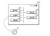
- FIG. 2 is a block diagram illustrating the internal configuration of the server device 100.
- the server device 100 includes a control unit 101, a storage unit 102, a communication unit 103, an operation unit 104, and a display unit 105.
- the control unit 101 is composed of a CPU (Central Processing Unit), a ROM (Read Only Memory), a RAM (Random Access Memory), and the like.
- the CPU included in the control unit 101 expands and executes various computer programs stored in the ROM or the storage unit 102 on the RAM, thereby causing the entire device to function as the simulation device of the present application.
- the server device 100 is only one embodiment of the simulation device, and may be any information processing device communicatively connected to the client device 200.
- the control unit 101 is not limited to the above configuration, and may be an arbitrary processing circuit or arithmetic circuit including a plurality of CPUs, a multi-core CPU, a GPU (Graphics Processing Unit), a microcomputer, a volatile or non-volatile memory, and the like. There may be.
- the control unit 101 may have functions such as a timer for measuring the elapsed time from giving the measurement start instruction to the measurement end instruction, a counter for counting the number, and a clock for outputting the date and time information.
- the storage unit 102 includes a storage device that uses an HDD (Hard Disk Drive), SSD (Solid State Drive), or the like.
- the storage unit 102 stores various computer programs executed by the control unit 101, data necessary for executing the computer programs, and the like.
- the computer program stored in the storage unit 102 includes a simulation program that simulates the behavior of the thermal battery 10.
- the simulation program is, for example, an execution binary.
- the theoretical formula that is the basis of the simulation program is described by an algebraic equation or a differential equation that expresses the behavior of the thermal battery 10.
- the simulation program may be prepared for each behavior of the simulation target, or may be prepared as one simulation program.
- the simulation programs are MATLAB (registered trademark), Amesim (registered trademark), Twin Builder (registered trademark), MATLAB & Simulink (registered trademark), Sampler (registered trademark), ANSYS (registered trademark), Abaqus (registered trademark), Modelica (registered trademark). It may be described by commercially available numerical analysis software or programming language such as Trademark), VHDL-AMS®, C language, C ++, Java®.
- the numerical analysis software may be a circuit simulator called 1D-CAE, or a simulator such as a finite element method or a finite volume method performed in a 3D shape. Alternatively, a degenerate model (ROM: Reduced-Order Model) based on these may be used.
- the program stored in the storage unit 102 may be provided by a non-temporary recording medium M in which the program is readablely recorded.
- the recording medium M is, for example, a portable memory such as a CD-ROM, a USB (Universal Serial Bus) memory, an SD (Secure Digital) card, a micro SD card, and a compact flash (registered trademark).
- the control unit 101 reads a program from the recording medium M using a reading device (not shown), and installs the read program in the storage unit 102.
- the program stored in the storage unit 102 may be provided by communication via the communication unit 103. In this case, the control unit 101 acquires a program through the communication unit 103, and installs the acquired program in the storage unit 102.
- the storage unit 102 may store a mathematical model obtained as a result of the simulation.
- a mathematical model is, for example, an executable code executed by a programming language or numerical analysis software.
- the mathematical model may be definition information or a library file referenced by a programming language or numerical analysis software.
- the storage unit 102 may have a battery table that stores information related to the configuration of the thermal battery 10 in association with the user ID.
- FIG. 3 is a conceptual diagram showing an example of a battery table.
- the battery table stores, for example, a battery ID that identifies the thermal battery 10, a user ID that identifies the user, and battery information in association with each other.
- the battery information registered in the battery table includes, for example, positive electrode and negative electrode information, electrolyte information, and the like.
- the information on the positive electrode and the negative electrode is information such as the active material name, thickness, diameter, open circuit potential, melting point, and heat resistant temperature of the positive electrode and the negative electrode.
- the electrolyte information is information such as ion species, transport number, diffusion coefficient, and conductivity.
- the battery table may include links that refer to information such as physical properties, operating conditions, and circuit configurations of the thermal battery 10.
- the information stored in the battery table may be registered by the administrator of the server device 100 or may be registered by the user via the client device 200.
- the information stored in the battery table can be used as part of the simulation conditions when simulating the behavior of the power storage device.
- the communication unit 103 includes an interface for communicating with the client device 200 through the communication network N.
- the communication unit 103 transmits the input information to the client device 200 and controls the information received from the client device 200 through the communication network N. Output to unit 101.
- the operation unit 104 is provided with an input interface such as a keyboard and a mouse, and accepts operations by the user.
- the display unit 105 includes a liquid crystal display device and the like, and displays information to be notified to the user.
- the server device 100 is configured to include the operation unit 104 and the display unit 105, but the operation unit 104 and the display unit 105 are not indispensable, and the operation is accepted through a computer connected to the outside of the server device 100. , The information to be notified may be output to an external computer.
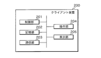
- FIG. 4 is a block diagram illustrating the internal configuration of the client device 200.
- the client device 200 is a personal computer, a smartphone, a tablet terminal, or the like, and includes a control unit 201, a storage unit 202, a communication unit 203, an operation unit 204, and a display unit 205.
- the control unit 201 is composed of a CPU, ROM, RAM, and the like.
- the CPU included in the control unit 201 executes control of the entire device by expanding and executing various computer programs stored in the ROM or the storage unit 202 on the RAM.
- the control unit 201 is not limited to the above configuration, and may be an arbitrary processing circuit or arithmetic circuit including a plurality of CPUs, a multi-core CPU, a microcomputer, and the like.
- the control unit 201 may have functions such as a timer for measuring the elapsed time from giving the measurement start instruction to the measurement end instruction, a counter for counting the number, and a clock for outputting the date and time information.
- the storage unit 202 is composed of a non-volatile memory such as EEPROM (Electronically Erasable Programmable Read Only Memory), and stores various computer programs and data.
- the computer program stored in the storage unit 202 includes a general-purpose or dedicated application used for exchanging information with the server device 100.
- An example of a general-purpose application program is a web browser. When accessing the server device 100 using a web browser, it is preferable to perform user authentication using a user ID and an authentication code, and communication between the server device 100 and the client device 200 only when the user authentication is successful. Should be allowed.
- the communication unit 203 includes an interface for communicating with the server device 100 through the communication network N.
- the communication unit 203 transmits the input information to the server device 100 and controls the information received from the server device 100 through the communication network N. Output to unit 201.
- the operation unit 204 is provided with an input interface such as a keyboard, mouse, and touch panel, and accepts operations by the user.
- the display unit 205 includes a liquid crystal display device and the like, and displays information to be notified to the user.
- the client device 200 is provided with the operation unit 204, but the client device 200 may be connected to an input interface such as a keyboard and a mouse.
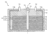
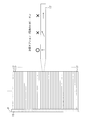
- FIG. 5 is a vertical cross-sectional view illustrating the configuration of the thermal battery 10.
- the thermal battery 10 includes, for example, a housing 11, a heat insulating member 12, a pair of output terminals 13, 13, a heat generating source 14, an igniter 15, a heating element 16, and a power generation cell 17.
- the housing 11 is, for example, a cylindrical container, and houses a heat insulating member 12, an output terminal 13, a heat generating source 14, an igniter 15, a heating element 16, and a power generation cell 17.
- the heat insulating member 12 surrounds the heating element 16 and the power generation cell 17.
- the heat insulating member 12 keeps the heating element 16 and the power generation cell 17 warm.
- the heat insulating member 12 can be formed of a material having low thermal conductivity, high heat resistance, and electrical insulation such as ceramic fiber.
- the output terminal 13 is a terminal for taking out a current from the power generation cell 17 via the connecting members 13a and 13b.
- the connecting member 13a is connected to the positive electrode layer 17a of the power generation cell 17 closest to the output terminal 13.
- the connecting member 13b is connected to the negative electrode layer 17c of the power generation cell 17 farthest from the output terminal 13.
- all the power generation cells 17 are electrically connected in series, and the battery as a whole becomes a bipolar battery.
- the igniter 15 shoots a spark and ignites the heat generating source 14.
- the heat generation source 14 is arranged along the central axis P of the housing 11.
- the heat generating source 14 includes a heat source such as gunpowder and burns when ignited by the igniter 15.
- Both the heating element 16 and the power generation cell 17 are formed in a disk shape and are laminated along the central axis P.
- the heating element 16 starts heat generation from the central axis P side to the outside by the combustion of the heat generation source 14, and heats the power generation cell 17.
- the heating element 16 is formed, for example, by a mixture of a metal powder and an oxidizing agent.
- the power generation cell 17 includes a positive electrode layer 17a, an electrolyte layer 17b, and a negative electrode layer 17c.
- the positive electrode layer 17a, the electrolyte layer 17b, and the negative electrode layer 17c are laminated in order along the central axis P.
- the positive electrode layer 17a is formed of, for example, iron disulfide.
- the electrolyte layer 17b contains a molten salt such as a communion mixture of lithium chloride and potassium chloride.
- the negative electrode layer 17c is formed of, for example, lithium silicon.
- the configuration of the thermal battery 10 in which four power generation cells 17 are stacked is shown.
- the number of power generation cells 17 to be stacked can be arbitrarily set according to specifications, applications, and the like, and for example, about 50 to 100 power generation cells 17 may be stacked.
- a heating element 14 is assumed on the central axis P, and a heating element 16 is assumed on the surface perpendicular to the central axis P.
- the mechanism of heat generation such as the heat generation source 14 and the heating element 16 is not limited to the heat of reaction and the heat of combustion.
- heater heating, frictional heat, temperature rise by adiabatic compression, microwave heating, arc heating, or the like may be used.
- FIG. 6 is a graph showing the temperature dependence of the ionic conductivity of a typical molten salt.
- the horizontal axis of the graph is temperature, and the vertical axis is the ionic conductivity of the molten salt.
- the ionic conductivity of the electrolyte layer 17b suddenly increases when the temperature exceeds a certain threshold value. This threshold temperature is often near the melting point of the molten salt.
- FIG. 7 is an explanatory diagram illustrating an outline of the simulation method.
- the server device 100 simulates the behavior of the thermal battery 10 based on the exothermic reaction for raising the temperature of the molten salt of the thermal battery 10 and the Joule heat generation.
- the exothermic reaction for raising the temperature of the molten salt is a reaction associated with ignition of the heating source 14 containing the explosive, and the chain of heat generation from the heating source 14 to the heating element 16 is described by, for example, the following Arrhenius reaction. It can be expressed by an expression.
- r is the reaction rate (1 / s)
- k 0 is the reaction rate constant (1 / s)
- E a is the activation energy (J / mol)
- R is the gas constant (J / mol / K)
- T Is the temperature (K)
- x f is the reaction rate
- p, q, and C 0 are constants.
- Q is the exothermic density (W / m 3 )
- ⁇ is the density (kg / m 3 )
- H p is the latent heat of reaction (J / kg).
- the above Arrhenius reaction formula can express the difference in explosive combustion depending on, for example, the configuration and arrangement of the heat insulating member 12.
- the server device 100 can execute a temperature simulation that does not assume the calorific value at a specific time in consideration of the filling density of the explosive, the explosive type, the total filling amount, the heat escape to the surroundings, and the like.
- Different substances are usually used for the heating source 14 and the heating element 16, and the heating rate is often faster in the heating source 14. Therefore, it is preferable to specify the reaction constants of the heating source 14 and the heating element 16.
- the Arrhenius reaction equation is given as an example of the reaction rate equation, and other reaction equations may be used.
- the server device 100 can use, for example, the Newman model for the electrochemical reaction.
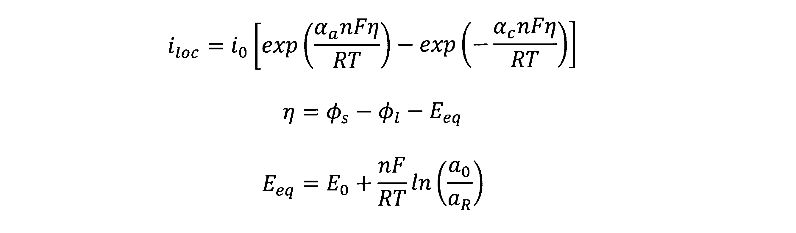
- the Newman model is described by the Nernst-Planck equation, the charge conservation equation, the diffusion equation, the Butler-Volmer equation, and the Nernst equation described below.
- the Nernst-Planck equation is an equation for solving ion electrophoresis and ion diffusion in an electrolytic solution or a porous electrode, and is expressed by the following equation.
- ⁇ l and eff are liquid phase conductivity (S / m), ⁇ l is liquid phase potential (V), R is gas constant (J / (K ⁇ mol)), T is temperature (K), and F. is the Faraday constant (C / mol), f is the activity coefficient, c l is the electrolyte ion concentration (mol / m 3), t + is a cation transport number, i tot is the reaction current density per volume.
- the liquid phase effective conductivity ⁇ l, eff is the apparent conductivity in the porous body, and is often expressed as a function of the liquid phase bulk conductivity and the solid phase volume ratio ⁇ s .
- the liquid phase refers to the ionic conduction portion, and in the thermal battery 10, it refers to the molten salt portion.
- the charge conservation formula is a formula that expresses electron conduction in a porous electrode or a current collector, and is expressed by the following formula.
- ⁇ s is the solid phase potential (V)
- ⁇ s is the solid phase conductivity (S / m)
- itot is the reaction current density per volume (A / m 3 ).
- the solid phase refers to an electron conductive portion, and in the thermal battery 10, it refers to a portion of the positive electrode material other than the molten salt, a portion of the negative electrode material other than the molten salt, and all other electronic conductors such as connecting members.
- the diffusion equation is an equation that expresses the diffusion of charge carriers in active material particles, and is expressed by the following equation.
- c s is the charge carrier concentration in the solid phase (mol / m 3 )
- t is the time (s)
- D s is the diffusion coefficient (m 2 / s) of the charge carrier in the solid phase.
- D s may be a function of charge carrier concentration in the electrode, electrode composition, SOC (State Of Charge), or temperature. SOC is the charging depth, and the fully charged state is represented by 1.0, and the fully discharged state is represented by 0.0.
- the Butler-Volmer equation is an equation that expresses the activation overvoltage in the charge transfer reaction that occurs at the interface between the solid phase and the liquid phase
- the Nernst equation is the definition equation of the equilibrium potential E eq , which are expressed by the following equations.
- i loc is the reaction current density (A / m 2 )
- i 0 is the exchange current density (A / m 2 )
- ⁇ a and ⁇ c are the transition coefficients
- ⁇ is the activation overvoltage (V)
- E eq is.
- E 0 is the standard equilibrium potential (V)
- n is the number of involved electrons
- a 0 is the oxidizing agent concentration
- a R is the reducing agent concentration (mol / m 3 ).
- Equation 6 shows the relational expression between the charge carrier concentration in the solid phase and the charge carrier flux involved in the charge transfer reaction on the surface of the active material particles.
- r 0 represents the radius (m) of the active material particles
- J s is the flux of the charge carrier (mol / m 2 s). In other words, J s disappears generated by a charge transfer reaction, the amount of charge carriers per unit area per unit time.
- Equation 7 is an equation expressing the relationship between the flux J s of the charge carrier and the reaction current density i loc .
- Equation 8 is an equation expressing the relationship between the reaction current density i loc and the reaction current density i tot per volume.
- S v is the specific surface area per unit volume (m 2 / m 3 ).
- S v may be a function of the radius r 0 of the active material particle.
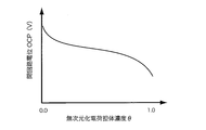
- FIG. 8 is a graph showing the relationship between the charge carrier concentration in the solid phase and the open circuit potential (OCP) in a typical positive electrode material.
- ⁇ is the dimensionless number, defined by the number 8, which is a function of charge carrier concentration c s.
- Equation 2 the second term on the right side of Equation 2 can be ignored.
- the liquid phase current will be calculated by Ohm's law. Since the term with strong non-linearity can be ignored, the calculation stability can be improved while reducing the calculation load.
- the Butler-Volmer equation was used as the equation expressing the activation overvoltage in the charge transfer reaction, but the Tafel equation may be used instead. Furthermore, it may be given in any table data format.
- the exchange current density may be a function of charge carrier concentration in the electrode, electrode composition, SOC, or temperature.
- the diffusion equation of the charge carrier in the solid phase described in Equation 4 may be omitted if the influence of the concentration overvoltage is negligible or if the calculation load is to be reduced.
- the NEWman model is shown as an example of a model representing the physical phenomenon of the thermal battery 10.
- actually measured data is often used.
- a single particle model may be used in which the electrodes are represented by a single active material particle.
- the single particle model for example, the non-patent document "Single-Particle Model for a Lithium-Ion Cell: Thermal Behavior, Meng Guo, Godfrey Sikha, and Ralph E. White, Journal of The Electrochemical Society, 158 (2) 122- The model disclosed in "132 (2011)” can be referred to.
- a polynomial model may be used that expresses the open circuit voltage OCV and internal resistance as a power function of temperature and SOC.
- the polynomial model for example, the non-patent document “Modeling the Dependence of the Discharge Behavior of a Lithium-Ion Battery on the Environmental Temperature, Ui Seong Kim, a Jaesin Yi, a Chee Burm Shin, Tae The model disclosed in "Journal of The Electrochemical Society, 158 (5) 611-618 (2011)” can be referred to.
- a model representing the characteristics of the thermal battery 10 such as an equivalent circuit model may be used.
- the molten salt of the thermal battery 10 is in a molten state when the heating element 16 generates heat due to the combustion of the heat generating source 14, and exhibits good ionic conductivity.
- a current flows through the positive electrode layer 17a and the negative electrode layer 17c of the power generation cell 17.
- Joule heat is generated, so that the exothermic reaction further proceeds by the Arrhenius-type reaction.
- the electrical resistance decreases and the current further increases.
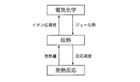
- the exothermic reaction and the Joule exothermic reaction in the thermal cell 10 are not independent physical phenomena, but are causal to each other, and proceed in relation to each other through physical phenomena such as heat transfer, that is, in an coupled manner.
- the server device 100 analyzes the exothermic reaction for raising the temperature of the molten salt and the Joule heat generation in a coupled manner, and calculates the current in consideration of, for example, the change in electrical resistance due to the temperature rise. I do.
- ⁇ is the density (kg / m 3 )
- C p is the specific heat (J / kg / K)
- T is the temperature (K)
- k is the thermal conductivity (W / m / K)
- Q is the internal heat generation (W / m / K). W / m 3 ).
- Q is heat of combustion in the heat generating source 14, heat of exothermic reaction and heat of Joule in the heating element 16, electrochemical reaction heat and heat of Joule in the power generation cell 17, and further in the molten salt of the electrolyte layer 17b. It also includes latent heat during melting. In order to reduce the calculation load, heat generation factors that are considered to have a small effect may be ignored as appropriate.
- Heat transfer is a phenomenon in which heat is transported by the flow of fluid
- radiation is a phenomenon in which heat is transported by electromagnetic waves.
- Heat transfer is represented by the number tens and heat radiation is represented by the number 11.
- q conv is the heat transfer flux (W / m 2 )
- h is the heat transfer coefficient (W / m 2 s)
- T is the outer surface temperature (K) of the thermal cell 10 calculated in the simulation process.
- T 0 is the outside air temperature (K)
- q rad is the heat radiation flux (W / m 2 )
- ⁇ is the blackbody coefficient
- ⁇ is the Stefan-Boltzmann coefficient (W / m 2 / T 4 ).
- thermo-fluid simulation program that considers the flow of fluid (mainly air) around the thermal battery may be added to this simulation program. This makes it possible to consider the heat exchange between the thermal battery and the fluid around the thermal battery.
- the calculation of thermal radiation does not depend on Equation 11, and the simulation model may include the objects around the thermal cell, and the thermal radiation simulation using the view factor may be performed.
- the person performing the simulation set the initial temperature appropriately. The reason is that the molten salt ion conductivity and the stability of the material change greatly depending on the temperature.
- a harmonic mean may be used for the thermal conductivity in the thickness direction, and an arithmetic mean may be used for other physical property values (thermal conductivity in the radial direction, specific heat, density).
- thermoelectric conductivity in the thickness direction of each layer is k i
- the thickness of each layer is t i
- the physical property value of each layer is ⁇ i
- the harmonic mean of the thermal conductivity in the thickness direction is represented by the number 12 and other physical properties.
- the arithmetic mean of the values may be represented by Equation 13.
- the server device 100 may calculate the current distribution in each layer by using orthogonal meshes that intersect in the axial direction (stacking direction) and the radial direction along the central axis P, respectively.
- the server device 100 can stabilize the calculation by using such an orthogonal mesh.
- the typical shape of the thermal cell shown in FIG. 5 is a cylindrical shape
- a two-dimensional axis target model is often used, but a one-dimensional, two-dimensional or three-dimensional shape may be used depending on the shape. You may use it.
- the simulation of the thermal battery 10 is executed by accessing the server device 100 from the client device 200.
- FIG. 9 is a schematic diagram showing an example of a user interface screen displayed on the client device 200.
- the user interface screen 210 shown in FIG. 9 shows an example of a screen displayed on the display unit 205 of the client device 200 after accessing the server device 100 from the client device 200 and being authenticated as a legitimate user. There is.
- the client device 200 communicates with the server device 100, acquires data for a display screen from the server device 100, and causes the display unit 205 to display the user interface screen 210 as shown in FIG.
- User authentication is not essential, and the server device 100 may be freely accessed. Alternatively, certification may be performed on a company, organization, region, or national basis.
- the user interface screen 210 is a screen provided with operation buttons, check boxes, etc. arranged as components of the user interface, and accepts operations by the user through the operation unit 204.
- the display field 211 is a display field for displaying user information such as a user ID and a previous access date and time.
- the client device 200 communicates with the server device 100, acquires user information such as a user ID and the previous access date and time from the server device 100, and displays the user information in the display field 211.
- the registration button 212A is an operation button for registering new power storage device information (battery information) in the server device 100.
- the client device 200 When the registration button 212A is operated by using the operation unit 204, the client device 200 causes the display unit 205 to display a reception screen for receiving battery information. When the reception of the battery information is completed, the client device 200 transmits the received battery information to the server device 100.
- the server device 100 registers the battery information received from the client device 200 in the battery table of the storage unit 102.
- the selection button 212B is an operation button for acquiring detailed information of the thermal battery 10, and is individually prepared according to the type and specifications of the thermal battery 10.
- the client device 200 acquires the detailed information of the selected thermal battery 10 from the server device 100.
- the acquired detailed information may be displayed on the display unit 205.
- Check boxes 213A to 213F are boxes for selecting the behavior to be simulated.
- the check box 213A is labeled "Time change of current”. That is, this check box 213A indicates that the behavior of the simulation target when selected by using the operation unit 204 is “time change of current”.
- the behavior of the simulation target is "time change of internal resistance”, “time change of electromotive force”, “time change of terminal voltage”, and “temperature”, respectively. It shows that it is “distribution” and "current distribution”.
- Option button 214 is an operation button for selecting a calculation option.
- the option button 214 accepts on / off of the option used for the calculation of the simulation.
- the calculation options for example, an option to calculate the whole using a representative power generation cell 17, an option to calculate by limiting the direction of the current only to the thickness direction, an option to specify the energization start condition, and an external circuit information are specified. Options etc. are included. These options will be described in Embodiments 2-5.
- the download button 215 is an operation button operated when downloading the simulation result from the server device 100.
- the simulation results that can be downloaded when the download button 215 is operated are numerical data, graphs, and other data obtained as the execution results when the server device 100 executes a simulation for the behavior selected by the check boxes 213A to 213F.
- the client device 200 requests the server device 100 to transmit the simulation result through the communication unit 203, and is transmitted from the server device 100 as a response. Receive the simulation result.
- the server device 100 is configured to transmit numerical data, graphs, and other data as simulation results to the client device 200.
- the server device 100 may transmit to the client device 200 a mathematical model in which the characteristics of the thermal battery 10 are mathematically described using algebraic equations, differential equations and characteristic parameters.
- the mathematical model is not just a theoretical model, but represents a model after simulation is performed on the selected thermal battery 10 and various parameters are adjusted.
- the mathematical model is, for example, MATLAB (registered trademark), Amesim (registered trademark), TwinBiller (registered trademark), MATLAB & Simulink (registered trademark), Sampler (registered trademark), ANSYS (registered trademark), Abaqus.
- FIG. 10 is a flowchart illustrating a procedure of processing executed by the server device 100 and the client device 200.
- the control unit 201 of the client device 200 receives the data for the display screen transmitted from the server device 100 after the user authentication, and displays the user interface screen 210 for selecting the simulation target on the display unit 205 (step S101). ).
- the control unit 201 accepts selections about the simulation target through the user interface screen 210 displayed on the display unit 205 (step S102). Specifically, the control unit 201 accepts the selection of the type of the thermal battery 10 using the selection button 212B and the selection of the behavior of the simulation target using the check boxes 213A to 213F.
- the control unit 201 displays a reception screen (not shown) for accepting the calculation option on the display unit 205 and accepts the calculation option (step S103).
- control unit 201 determines whether or not the request for downloading the result has been accepted (step S104). For example, when the download button 215 is operated on the user interface screen 210 shown in FIG. 9, the control unit 201 determines that the request for downloading the result has been accepted. When it is determined that the request is not accepted (S104: NO), the control unit 201 waits until the request for result download is accepted. Alternatively, it may be configured to accept a result download request after the calculation.
- the control unit 201 transmits the information of the simulation target selected in step S102 and the information of the calculation option received in step S103 to the server device 100 through the communication unit 203. Then (step S105), the simulation result is requested to be downloaded. If the calculation option is not accepted in step S103, the control unit 201 may transmit information on the default calculation option to the server device 100.
- the server device 100 receives the information of the simulation target and the calculation option transmitted from the client device 200 in the communication unit 103 (step S106).
- the control unit 101 of the server device 100 executes the simulation based on the information of the simulation target and the calculation option received through the communication unit 103 (step S107).
- the control unit 101 simulates the behavior of the thermal battery 10 by executing a simulation program corresponding to the behavior of the simulation target.
- the calculation options selected by the user are applied when running the simulation program.
- the heating element 16 starts to generate heat due to the combustion of the heat generating source 14, and when the melting point is exceeded, the molten salt is in a molten state, and a current flows through the positive electrode layer 17a and the negative electrode layer 17c of the power generation cell 17.
- the control unit 101 couples the exothermic reaction and the Joule thermal reaction, calculates the reaction rate r in the exothermic reaction by the Allenius reaction formula shown in Equation 1, and calculates the electromotive force and the internal resistance of the thermal cell 10 by, for example, the Newman model. To do.
- the electromotive force of the thermal battery 10 is a value obtained by adding the equilibrium potentials E eq of each electrode over the entire battery, and is a voltage between the positive and negative output terminals 13 when no load is applied.
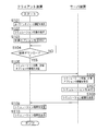
- the control unit 101 uses the procedure for calculating the electromotive force of the thermal battery 10, the procedure for calculating the internal resistance of the thermal battery 10, and the external load resistance, electromotive force, and internal resistance of the thermal battery 10 in the next calculation step.
- the current calculation may be performed using a submodel that repeats the procedure for calculating the current value.
- the circuit diagram of the submodel is shown in FIG.
- EMF electromotive force of the thermal battery 10 r (T) the internal resistance of the thermal battery 10 in the battery temperature T, the external load resistance R, the voltage between the terminals of the thermal battery 10 V e, the current of the thermal battery 10
- the control unit 101 can calculate the current I e from the equation 16 and use it as a boundary condition in the next calculation step.
- the external load resistance of the thermal battery 10 does not necessarily have to be a resistor, and may include other circuit elements such as a capacitor and an inductor.
- the value of the external load resistance may represent the characteristics of the actual load, or a virtual value may be used.
- the current I e described here can be considered to be the maximum value of the current that can be discharged from the thermal battery 10. Therefore, as an alternative, an arbitrary value of 0.0 (A) or more and less than I e may be used as the current flowing through the thermal battery 10 as a boundary condition in the next calculation step.
- the control unit 101 transmits the simulation result to the client device 200 through the communication unit 103 (step S108).
- the simulation result transmitted in step S108 may be numerical data, or may be a graph, contour diagram, moving image, or the like generated from the numerical data. It may be a mathematical model representing the characteristics of the thermal battery 10.
- the client device 200 receives the simulation result transmitted from the server device 100 in the communication unit 203 (step S109).
- the control unit 201 of the client device 200 causes the display unit 205 to display the received simulation result (step S110).
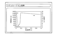
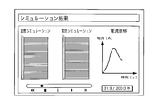
- FIG. 12 is a schematic diagram showing a display example of the simulation result.
- FIG. 12 shows the simulation results relating to the time change of the current and the internal resistance of the thermal battery 10. That is, FIG. 12 shows the simulation result when both the check boxes 213A and 213B are selected on the user interface screen 210.
- the simulation result is represented by, for example, a graph in which the elapsed time (s) since the heat generation source 14 is ignited is plotted on the horizontal axis, and the internal resistance ( ⁇ ) and the total current (A) are plotted on the vertical axis. In the example of FIG. 12, it is shown that the internal resistance decreases and the current starts to flow about 0.1 seconds after the heat generating source 14 is ignited.
- the display unit 205 of the client device 200 shows the elapsed time (s) after the heat generation source 14 is ignited on the horizontal axis.
- a graph with the power (V) or terminal voltage (V) on the vertical axis is displayed as the simulation result.
- the display unit 205 of the client device 200 displays the temperature (temperature distribution) or the magnitude of the current density (current density distribution) contour diagram at each position inside the thermal battery 10.
- the server device 100 simulates the behavior of the thermal battery 10 in consideration of the exothermic reaction for raising the temperature of the molten salt of the thermal battery 10 and the Joule heat generation. Can be done. Even if the user is not familiar with the physical phenomenon in the thermal battery 10, the user can acquire the detailed simulation result of the thermal battery 10 by selecting the type of the thermal battery and the behavior of the simulation target from the client device 200. Can be done.
- FIG. 13 is an explanatory diagram illustrating the calculation options in the second embodiment.
- the thermal battery 10 includes a plurality of power generation cells 17.
- the thermal battery 10 includes a power generation cell 17 having about 50 to 100 layers.
- the server device 100 prepares an option to calculate the whole using the representative power generation cell 17 as a calculation option, and when the user turns on this calculation option, the current is generated by using the representative power generation cell 17.
- Calculate electrochemistry
- the configuration of the thermal battery 10 is shown in a simplified manner, and the power generation cell 17 to be calculated is shown by hatching.
- the representative power generation cell 17 is preset in the server device 100. Alternatively, the representative power generation cell 17 is selected by the user. For example, when one of the five consecutive power generation cells 17 is set as the representative power generation cell 17, the calculation load of electrochemical is reduced to about 1/5.
- FIG. 14 is an explanatory diagram illustrating the calculation options in the third embodiment. Since each layer of the thermal battery 10 is thinner than the radial direction, it is expected that the direction of the current density vector almost coincides with the thickness direction. Therefore, the server device 100 prepares an option for calculating the current direction only in the thickness direction as a calculation option, and when the user turns on this calculation option, the current flowing in the radial direction is ignored. Then, the current is calculated using only the current flowing in the thickness direction.
- server device 100 in the third embodiment can reduce the number of dimensions of the current calculation to one dimension, the calculation load can be reduced.
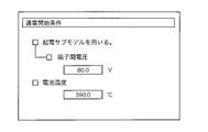
- FIG. 15 is an input screen of the energization start condition in the fourth embodiment. As shown in FIG. 15, when the voltage between the terminals of the thermal battery 10 exceeds a predetermined value, energization may be started.
- energization may be started when the temperature of the thermal battery 10 exceeds a predetermined temperature. Regardless of which method is used, care must be taken in the calculation because care must be taken so that the voltage between the terminals of the thermal battery 10 does not become negative.
- the simulation program provided by the server device 100 may include not only the thermal battery 10 but also an electric circuit connected to the thermal battery 10.
- the client user may perform an electric circuit simulation including the thermal battery 10 on the server device 100.
- the electric circuit may include a capacitor, an inductor, a diode, a semiconductor element (thyristor, IGBT, MOSFET, etc.) in addition to the ohm resistor.
- the boundary conditions given to the thermal battery 10 are not necessarily those due to the passive element, but may include constant current conditions, constant voltage conditions, constant power conditions, and the like.
- the value may fluctuate with time, or the boundary condition may change during the discharge process (for example, the constant current boundary condition changes to the constant power boundary condition).
- the electric circuit may include a control circuit that performs switching operation, load switching, fixed value control, target value control, and the like.
- the circuit connected to the thermal battery 10 may include a thermal circuit.
- a thermal circuit the heat capacity and thermal resistance are expressed by a differential equation similar to that of an electric circuit.
- the temperature behavior of the system is calculated like a circuit simulation.
- the thermal circuit may include a heat source other than the thermal battery 10, heat capacity, thermal resistance, heat dissipation boundary, and constant temperature boundary. Values such as heat source, heat capacity, and thermal resistance may fluctuate with time, and boundary conditions may change during the discharge process.
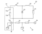
- FIG. 16 is a circuit diagram showing an example of a circuit simulation including a thermal battery 10, an electric circuit 20, and a thermal circuit 30.
- the thermal battery 10 is treated as a heat source and a current source (or voltage source).
- the thermal battery 10 includes a power generating unit 10a, an internal resistance 10b, a heat source 10c, and a heat capacity 10d.
- the electric circuit 20 includes, for example, a semiconductor element 21, an inductor 22, a diode 23, and a load 24.
- the thermal circuit 30 includes, for example, a load heat capacity 31, a thermal resistance 32 between the thermal battery 10 and the load, a thermal resistance 33 between the load and the outside air, and an outside air temperature 34.
- the circuit elements may be freely combined according to the load and usage conditions.
- the exothermic reaction in the thermal battery 10 is expressed by the Arrhenius reaction formula, but there is a problem that the calculation load becomes large. Therefore, the server device 100 according to the sixth embodiment calculates the time transition of the exothermic reaction by acquiring the experimental result or the simulation result of the exothermic density in advance and giving the exothermic density as a function of the position and the time. Is omitted.
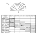
- FIG. 17 is an explanatory diagram illustrating how to give the heat generation density in the sixth embodiment.
- the thermal battery 10 is divided into five regions from the inside (central axis P side) to the outside from the region 10A to the region 10E, and the time dependence of the heat generation density is given to each of the regions 10A to 10E.
- An example is shown.
- region 10A indicates that heat was generated in the time zone of 0.03 to 0.31 sec from the start of ignition, and the heat generation density was H1 (W / m 3 ).
- the server device 100 can omit the calculation of the time transition of the exothermic reaction using the Arenius reaction equation by giving the exothermic density as a function of the position and the time.
- the calculation load can be reduced.
- the temperature and the current-voltage distribution are closely related, so the mutual relationship between these values is important information in the field of design and development.
- a steep temperature distribution may appear in the radial direction of the thermal battery 10
- the thermal battery 10 is a bipolar battery.
- the relationship between temperature, current, and voltage is often inconsistent with intuition, and it is difficult to understand the phenomenon, because the overall performance may be significantly impaired if there are electrodes with insufficient electromotive force. It is often difficult.
- FIG. 18 is a schematic diagram showing an example of a result display screen according to the seventh embodiment.
- the temperature and voltage distribution may be an animation of the contour diagram, or may be updated in real time as the simulation progresses.
- the current is displayed as a graph in FIG. 18, the graph may be drawn in real time as the simulation progresses.
- the voltage between terminals may be displayed as a graph, or the vector diagram of the current distribution may be superimposed on the contour diagram of the voltage distribution. It is not necessary to display all the physical quantities described in this paragraph, and two or more physical quantities selected as appropriate may be displayed.
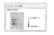
- the thermal battery 10 Since the thermal battery 10 is activated by melting the electrolyte, it goes without saying that the electrolyte does not melt and energization does not start if the amount of heat generated is too small. However, if excessive heat generation is applied, the temperature rises too much, and there is a concern that the materials and connecting members constituting the power generation cell may be burnt or a material decomposition reaction may occur. Therefore, the maximum temperature reached by the heating source 14 and the heating element 16 is required to be higher than the melting point of the molten salt and lower than the heat resistant temperature of each component. This is generally a difficult task.
- FIG. 19 is a schematic diagram showing an example of a result display screen according to the eighth embodiment.
- FIG. 19 is a contour diagram showing "(heat resistant temperature)-(simulation temperature)", but the small value means that the temperature has risen to near the heat resistant temperature, and the design temperature Indicates that the safety margin is small.
- the server administrator transfers the thermal battery simulation program to the client by means of a recording medium such as a DVD-ROM. It may be provided to the user and the simulation may be performed locally on the client terminal.
- a download format via communication may be used as a means for providing the thermal battery simulation program.
- the simulation program provided to the client user includes not only the thermal battery part and the circuit part including the external load described mainly in the embodiment, but also a digital control circuit for switching operation and load switching. It may be.
- the simulation program provided to the client user may be completely concealed (that is, not editable) at the will of the developer of the development support device, or only some parameters can be changed by the client user. It may be partially concealed.
- the client device 200 may be able to select the format of the simulation program to be downloaded from the server device 100 by numerical analysis software or a programming language. As a result, the client user can use this simulation program with his / her own numerical analysis software or programming language.
- the thermal battery 10 has described only the discharge process as the primary battery, but any battery having a feature that the molten salt melts and energization starts when the temperature rises is a secondary battery. May be good. That is, the server device 100 (or the client device 200) may perform a simulation including both the discharging process and the charging process. When considering the discharge process, it is only necessary to invert the sign of the current boundary condition in the calculation model described in the embodiment.
Landscapes
- Engineering & Computer Science (AREA)
- Physics & Mathematics (AREA)
- Chemical & Material Sciences (AREA)
- Chemical Kinetics & Catalysis (AREA)
- Electrochemistry (AREA)
- General Chemical & Material Sciences (AREA)
- Manufacturing & Machinery (AREA)
- Theoretical Computer Science (AREA)
- Evolutionary Computation (AREA)
- Geometry (AREA)
- General Engineering & Computer Science (AREA)
- General Physics & Mathematics (AREA)
- Computer Hardware Design (AREA)
- Secondary Cells (AREA)
- Primary Cells (AREA)
Abstract
Description
この構成によれば、溶融塩を昇温させる過程を含むような電池についての挙動をシミュレートできる。
この構成によれば、本シミュレーション装置は、溶融塩を昇温させる過程を含むような電池についての挙動をシミュレートできる。例えば、本シミュレーション装置は、発熱反応やジュール発熱の時間推移を反映させた電池内部の抵抗、電流、端子電圧等の時間変化、並びに、電池内部の電流密度分布、電位分布及び温度分布を計算することができる。
この構成によれば、本コンピュータプログラムは、溶融塩を昇温させる過程を含むような電池についての挙動をシミュレートできる。例えば、本コンピュータプログラムは、発熱反応やジュール発熱の時間推移を反映させた電池内部の抵抗、電流、端子電圧等の時間変化、並びに、電池内部の電流密度分布、電位分布及び温度分布を計算することができる。これらの発熱に加えて、電気化学反応による反応熱を加味することもでき、その場合はより精緻なシミュレーションを実施できる。さらに、「融解潜熱による吸熱」、或いは「エントロピーによる吸発熱」を考慮してもよい。
(実施の形態1)
図1は本実施の形態に係るシミュレーションシステムの全体構成を説明する模式図である。本実施の形態に係るシミュレーションシステムは、通信網Nを介して互いに通信可能に接続されるサーバ装置100とクライアント装置200,200,…,200とを備える。サーバ装置100は、クライアント装置200からの要求に応じて、熱電池10(図5を参照)の挙動をシミュレートし、シミュレーション結果をクライアント装置200へ提供する。
図5は熱電池10の構成を説明する縦断面図である。熱電池10は、例えば、筐体11、断熱部材12、一対の出力端子13,13、発熱源14、点火具15、発熱体16、及び発電セル17を備える。
図7はシミュレーション手法の概略を説明する説明図である。本実施の形態に係るサーバ装置100は、熱電池10の溶融塩を昇温させるための発熱反応と、ジュール発熱とに基づき、熱電池10の挙動をシミュレートする。ここで、溶融塩を昇温させるための発熱反応とは、火薬を含む発熱源14への点火に伴う反応であり、発熱源14から発熱体16への発熱の連鎖を、例えば以下のアレニウス反応式で表現することができる。














実施の形態2では、代表の発電セル17を用いて全体を計算する計算オプションについて説明する。
実施の形態3では、電流の向きを厚み方向のみに限定して計算する計算オプションについて説明する。
これまで、サブモデルを用いて電流境界条件を決定する方法について述べた。代替的に、サブモデルの値を参考にして、熱電池モデルの境界条件を決定してもよい。
ここまで熱電池10部分のシミュレーションについて述べてきたが、実施の形態5では、熱電池10に接続される回路(後述する電気回路又は熱回路)をシミュレーションに含む場合について述べる。
実施の形態6では、発熱反応における発熱密度を位置と時間との関数として与える構成について説明する。
実施の形態7では、シミュレーション結果の効果的な表示方法の例を述べる。
実施の形態8では、シミュレーション結果の効果的な表示方法の他の例を述べる。
101 制御部
102 記憶部
103 通信部
104 操作部
105 表示部
200 クライアント装置
201 制御部
202 記憶部
203 通信部
204 操作部
205 表示部
N 通信網
Claims (18)
- 溶融塩を電解質とする電池のシミュレーション方法であって、
前記溶融塩を昇温させる過程を含む前記電池の挙動をシミュレートする
シミュレーション方法。 - 前記溶融塩のイオン伝導率は温度の関数であり、
前記イオン伝導率は、第1の閾値温度以下で絶縁性の値を示し、第2の閾値温度以上で導電性の値を示す
請求項1に記載のシミュレーション方法。 - 前記溶融塩を昇温させるための発熱反応に基づき、前記電池の挙動をシミュレートする
請求項2又は請求項3に記載のシミュレーション方法。 - 前記発熱反応とジュール発熱との連成解析により前記電池の挙動をシミュレートする
請求項3に記載のシミュレーション方法。 - 前記電池は、
発熱源と、
前記発熱源の燃焼により発熱が開始する発熱体と、
正極層、電解質層及び負極層を積層してなる発電セルと
を含み、
前記電池は、前記正極層、前記電解質層及び前記負極層の積層方向に沿って、前記発熱体及び前記発電セルが積層されたバイポーラ型の熱電池である
請求項1から請求項4の何れか1つに記載のシミュレーション方法。 - 前記発熱源の充填量と温度とに基づき、前記発熱反応における発熱量を計算する
請求項5に記載のシミュレーション方法。 - 各層の物性値から算出した等価物性値を用いて、伝熱を計算する
請求項5に記載のシミュレーション方法。 - 前記発熱反応における発熱密度を位置と時間との関数として与える
請求項5に記載のシミュレーション方法。 - 選択した一部の層を代表層として用いて各層の電流分布を計算する
請求項5に記載のシミュレーション方法。 - 前記積層方向の電流成分のみを用いて各層の電流分布を計算する
請求項5に記載のシミュレーション方法。 - 前記積層方向及び前記積層方向と交差する交差方向にメッシュ分割した要素を用いて各層の電流分布を計算する
請求項5に記載のシミュレーション方法。 - 前記電池の起電力を計算する手順と、
前記電池の内部抵抗を計算する手順と、
前記電池の外部負荷抵抗、並びに、計算した起電力及び内部抵抗の値に基づき、次の計算ステップにおける電流値を計算する手順と
を繰り返すサブモデルを用いて、電流計算を実行する
請求項5に記載のシミュレーション方法。 - 溶融塩を電解質とする電池に関して、前記溶融塩を昇温させる過程を含む前記電池の挙動をシミュレートするシミュレーション実行部と、
前記シミュレーション実行部によるシミュレーション結果を出力する出力部と
を備えるシミュレーション装置。 - 前記シミュレーション実行部は、前記電池に接続された電気回路及び熱回路の少なくとも一方をシミュレートする
請求項13に記載のシミュレーション装置。 - 前記シミュレーション実行部は、温度分布、電圧分布、電流密度分布、電流値又は端子間電圧の経時変化のうち少なくとも2つのグラフを生成し、
前記出力部は、生成した前記2つのグラフを同一画面に表示させるべく、前記グラフのデータを表示装置へ出力する
請求項13又は請求項14に記載のシミュレーション装置。 - コンピュータに、
溶融塩を電解質とする電池に関して、前記溶融塩を昇温させる過程を含む前記電池の挙動をシミュレートする
処理を実行させるためのシミュレーションプログラム。 - 前記コンピュータに、
前記電池に接続された電気回路及び熱回路の少なくとも一方をシミュレートする
処理を実行させるための請求項16に記載のシミュレーションプログラム。 - 前記コンピュータに、
温度分布、電圧分布、電流密度分布、電流値又は端子間電圧の経時変化のうち少なくとも2つのグラフを生成し、
生成した前記2つのグラフを同一画面に表示させるべく、前記グラフのデータを表示装置へ出力する
処理を実行させるための請求項16又は請求項17に記載のシミュレーションプログラム。
Priority Applications (3)
| Application Number | Priority Date | Filing Date | Title |
|---|---|---|---|
| JP2021507403A JP7501519B2 (ja) | 2019-03-19 | 2020-03-18 | シミュレーション方法、シミュレーション装置、及びシミュレーションプログラム |
| US17/440,579 US12271664B2 (en) | 2019-03-19 | 2020-03-18 | Simulation method of a battery using molten salt as an electrolyte, and associated simulation device |
| EP20773733.9A EP3944121A4 (en) | 2019-03-19 | 2020-03-18 | SIMULATION METHOD, SIMULATION DEVICE AND SIMULATION PROGRAM |
Applications Claiming Priority (2)
| Application Number | Priority Date | Filing Date | Title |
|---|---|---|---|
| JP2019051225 | 2019-03-19 | ||
| JP2019-051225 | 2019-03-19 |
Publications (1)
| Publication Number | Publication Date |
|---|---|
| WO2020189730A1 true WO2020189730A1 (ja) | 2020-09-24 |
Family
ID=72520260
Family Applications (1)
| Application Number | Title | Priority Date | Filing Date |
|---|---|---|---|
| PCT/JP2020/012068 Ceased WO2020189730A1 (ja) | 2019-03-19 | 2020-03-18 | シミュレーション方法、シミュレーション装置、及びシミュレーションプログラム |
Country Status (4)
| Country | Link |
|---|---|
| US (1) | US12271664B2 (ja) |
| EP (1) | EP3944121A4 (ja) |
| JP (1) | JP7501519B2 (ja) |
| WO (1) | WO2020189730A1 (ja) |
Cited By (2)
| Publication number | Priority date | Publication date | Assignee | Title |
|---|---|---|---|---|
| CN114757068A (zh) * | 2022-03-28 | 2022-07-15 | 清华大学 | 用于单相接地故障的定子铁心电弧烧损的建模分析方法 |
| WO2025225984A1 (ko) * | 2024-04-22 | 2025-10-30 | 주식회사 엘지에너지솔루션 | 열 발생 시뮬레이션 장치 및 이의 동작 방법 |
Families Citing this family (5)
| Publication number | Priority date | Publication date | Assignee | Title |
|---|---|---|---|---|
| CN115825145B (zh) * | 2022-11-18 | 2023-07-11 | 哈尔滨工业大学 | 高温液态熔盐热辐射及导热参数联合测量装置及反演方法 |
| CN115758050B (zh) * | 2022-12-09 | 2026-05-15 | 美克生能源科技股份有限公司 | 用于参数辨识的计算终端 |
| CN116150995B (zh) * | 2023-02-21 | 2023-07-25 | 东南大学 | 一种开关电弧模型的快速仿真方法 |
| CN116341297B (zh) * | 2023-05-31 | 2023-11-03 | 宁德时代新能源科技股份有限公司 | 电池仿真方法、装置、电子设备及计算机可读存储介质 |
| US12535783B2 (en) * | 2023-08-04 | 2026-01-27 | Scibot Technology LLC | Self-adaptive lithium-ion battery method using knowledge-reinforced machine learning and kalman filtering, electronic device, and storage medium |
Citations (4)
| Publication number | Priority date | Publication date | Assignee | Title |
|---|---|---|---|---|
| US5428560A (en) * | 1992-04-08 | 1995-06-27 | Aerospatiale Societe Nationale Industrielle | Simulator, in particular of thermal batteries |
| JP2001152397A (ja) * | 1999-11-19 | 2001-06-05 | Ebara Corp | めっき解析方法 |
| JP2001179336A (ja) | 2000-11-07 | 2001-07-03 | Nkk Corp | マーク付き鋼板の製造方法 |
| JP2016194919A (ja) * | 2015-03-31 | 2016-11-17 | 日本碍子株式会社 | ハニカム構造体の解析方法、そのプログラム及び解析装置 |
Family Cites Families (18)
| Publication number | Priority date | Publication date | Assignee | Title |
|---|---|---|---|---|
| JPH1114507A (ja) | 1997-06-19 | 1999-01-22 | Denso Corp | 車両シミュレーション装置 |
| JP2004220600A (ja) | 2002-12-26 | 2004-08-05 | Ricoh Co Ltd | 製品設計支援システム、製品設計支援方法及びプログラム |
| JP4576903B2 (ja) | 2004-06-29 | 2010-11-10 | 三菱化学株式会社 | 温度分布評価方法並びにシミュレーション装置及びシミュレーションプログラム |
| JP2009106059A (ja) | 2007-10-23 | 2009-05-14 | Meidensha Corp | バッテリシミュレータ |
| JP5362273B2 (ja) | 2008-07-04 | 2013-12-11 | パナソニック株式会社 | 溶融塩及び熱電池 |
| JP5487719B2 (ja) | 2009-05-19 | 2014-05-07 | トヨタ自動車株式会社 | 全固体リチウム二次電池の製造方法、及び当該製造方法により得られる全固体リチウム二次電池 |
| JP2012069496A (ja) | 2010-09-27 | 2012-04-05 | Denso Corp | 電池加熱装置 |
| JP6001823B2 (ja) | 2011-01-24 | 2016-10-05 | 株式会社豊田中央研究所 | 二次電池のシミュレーション装置 |
| JP2012174570A (ja) | 2011-02-23 | 2012-09-10 | Sumitomo Electric Ind Ltd | 組電池 |
| JP2013089549A (ja) | 2011-10-21 | 2013-05-13 | Sumitomo Electric Ind Ltd | 閉鎖型溶融塩組電池 |
| JP2013101884A (ja) | 2011-11-09 | 2013-05-23 | Toyota Motor Corp | 二次電池の温度推定方法および二次電池の制御方法 |
| JP2015050062A (ja) | 2013-09-02 | 2015-03-16 | トヨタ自動車株式会社 | リチウムイオン二次電池の設計方法 |
| KR101735033B1 (ko) * | 2014-05-16 | 2017-05-12 | 주식회사 엘지화학 | 배터리 냉각 시스템 시뮬레이션 장치 및 방법 |
| JP2016090399A (ja) | 2014-11-05 | 2016-05-23 | 日本電信電話株式会社 | 短絡検出方法、短絡検出システムおよび短絡電流値算出方法 |
| US10422760B2 (en) | 2015-03-31 | 2019-09-24 | Ngk Insulators, Ltd. | Method for analyzing honeycomb structure, and program and analysis device for the same |
| JP2017059343A (ja) | 2015-09-15 | 2017-03-23 | 三菱製紙株式会社 | リチウムイオン二次電池用部材の評価方法 |
| JP6647058B2 (ja) | 2016-02-02 | 2020-02-14 | 株式会社協和エクシオ | バックアップ電源システム |
| US20200210541A1 (en) * | 2018-12-31 | 2020-07-02 | Chongqing Jinkang New Energy Vehicle, Ltd. | Detection of Lithium Plating Potential with Multi-Particle Reduced-Order Model |
-
2020
- 2020-03-18 WO PCT/JP2020/012068 patent/WO2020189730A1/ja not_active Ceased
- 2020-03-18 EP EP20773733.9A patent/EP3944121A4/en active Pending
- 2020-03-18 JP JP2021507403A patent/JP7501519B2/ja active Active
- 2020-03-18 US US17/440,579 patent/US12271664B2/en active Active
Patent Citations (4)
| Publication number | Priority date | Publication date | Assignee | Title |
|---|---|---|---|---|
| US5428560A (en) * | 1992-04-08 | 1995-06-27 | Aerospatiale Societe Nationale Industrielle | Simulator, in particular of thermal batteries |
| JP2001152397A (ja) * | 1999-11-19 | 2001-06-05 | Ebara Corp | めっき解析方法 |
| JP2001179336A (ja) | 2000-11-07 | 2001-07-03 | Nkk Corp | マーク付き鋼板の製造方法 |
| JP2016194919A (ja) * | 2015-03-31 | 2016-11-17 | 日本碍子株式会社 | ハニカム構造体の解析方法、そのプログラム及び解析装置 |
Non-Patent Citations (4)
| Title |
|---|
| MENG GUOGODFREY SIKHARALPH E. WHITE: "Single-Particle Model for a Lithium-Ion Cell: Thermal Behavio", JOURNAL OF THE ELECTROCHEMICAL SOCIETY, vol. 158, no. 2, 2011, pages 122 - 132 |
| SCOTT, A. R.: "Multiphysics modeling of thermal batteries", 2016, XP055741731, Retrieved from the Internet <URL:https://creb.umd.edu/sites/all/files/14-Roberts-Multiphysics-modeling-of-thermal-batteries-at-Sandia.pdf> [retrieved on 20200608] * |
| See also references of EP3944121A4 |
| UI SEONG KIMA JAESHIN YIA CHEE BURM SHINTAEYOUNG HAN, BSEONGYONG PARK: "Modeling the Dependence of the Discharge Behavior of a Lithium-Ion Battery on the Environmental Temperature", JOURNAL OF THE ELECTROCHEMICAL SOCIETY, vol. 158, no. 5, 2011, pages 611 - 618 |
Cited By (2)
| Publication number | Priority date | Publication date | Assignee | Title |
|---|---|---|---|---|
| CN114757068A (zh) * | 2022-03-28 | 2022-07-15 | 清华大学 | 用于单相接地故障的定子铁心电弧烧损的建模分析方法 |
| WO2025225984A1 (ko) * | 2024-04-22 | 2025-10-30 | 주식회사 엘지에너지솔루션 | 열 발생 시뮬레이션 장치 및 이의 동작 방법 |
Also Published As
| Publication number | Publication date |
|---|---|
| JPWO2020189730A1 (ja) | 2020-09-24 |
| US20220188479A1 (en) | 2022-06-16 |
| US12271664B2 (en) | 2025-04-08 |
| EP3944121A4 (en) | 2022-06-01 |
| JP7501519B2 (ja) | 2024-06-18 |
| EP3944121A1 (en) | 2022-01-26 |
Similar Documents
| Publication | Publication Date | Title |
|---|---|---|
| JP7501519B2 (ja) | シミュレーション方法、シミュレーション装置、及びシミュレーションプログラム | |
| Christensen et al. | An efficient parallelizable 3D thermoelectrochemical model of a Li-ion cell | |
| Coman et al. | Modelling Li-ion cell thermal runaway triggered by an internal short circuit device using an efficiency factor and Arrhenius formulations | |
| Wu et al. | Thermal design for the pouch-type large-format lithium-ion batteries: I. Thermo-electrical modeling and origins of temperature non-uniformity | |
| Fu et al. | Modeling, validation and analysis of mechanical stress generation and dimension changes of a pouch type high power Li-ion battery | |
| Jung et al. | Multi-dimensional modeling of large-scale lithium-ion batteries | |
| Amiribavandpour et al. | An improved theoretical electrochemical-thermal modelling of lithium-ion battery packs in electric vehicles | |
| Guo et al. | A distributed thermal model for a Li-ion electrode plate pair | |
| Liu et al. | Integrated computation model of lithium-ion battery subject to nail penetration | |
| Northrop et al. | Efficient simulation and reformulation of lithium-ion battery models for enabling electric transportation | |
| Northrop et al. | Efficient simulation and model reformulation of two-dimensional electrochemical thermal behavior of lithium-ion batteries | |
| JP6699795B1 (ja) | シミュレーション方法、シミュレーション装置、及びコンピュータプログラム | |
| JP7480541B2 (ja) | 開発支援装置、及び開発支援方法 | |
| CA2395655A1 (en) | Method and apparatus for characterizing high-energy electrochemical cells using power functions obtained from calorimetry | |
| Torabi et al. | Study of thermal–runaway in batteries I. Theoretical study and formulation | |
| Jia et al. | Dynamics of Intra‐Cell Thermal Front Propagation in Lithium‐Ion Battery Safety Issues | |
| JP7794220B2 (ja) | 情報処理装置、端末装置、情報提供方法、情報処理方法、及びコンピュータプログラム | |
| Quarti et al. | Model‐based overpotential deconvolution, partial impedance spectroscopy, and sensitivity analysis of a lithium‐ion cell with blend cathode | |
| Same et al. | Effect of thermal parameters on behaviour of a lithium-ion battery: simulation study | |
| He et al. | A transient multi-path decentralized resistance-capacity network model for prismatic lithium-ion batteries based on genetic algorithm optimization | |
| Torrano et al. | Two-way coupled electro-thermal modeling of a 18650 NMC Li-Ion cell arrangement under highly dynamic conditions: Cells properties determination and experimental validation | |
| Nema et al. | Investigation of transient heat generation from high energy density Li-ion battery for effective thermal management | |
| US20220188481A1 (en) | Development support device, development support method, and computer program | |
| Wang et al. | Coupled Electrochemical‐Thermal‐Mechanical Modeling and Simulation of Multi‐Scale Heterogeneous Lithium‐Ion Batteries | |
| CN115358042B (zh) | 产热功率预测方法、装置、计算机设备和存储介质 |
Legal Events
| Date | Code | Title | Description |
|---|---|---|---|
| 121 | Ep: the epo has been informed by wipo that ep was designated in this application |
Ref document number: 20773733 Country of ref document: EP Kind code of ref document: A1 |
|
| ENP | Entry into the national phase |
Ref document number: 2021507403 Country of ref document: JP Kind code of ref document: A |
|
| NENP | Non-entry into the national phase |
Ref country code: DE |
|
| ENP | Entry into the national phase |
Ref document number: 2020773733 Country of ref document: EP Effective date: 20211019 |
|
| WWG | Wipo information: grant in national office |
Ref document number: 17440579 Country of ref document: US |